Performance Based Analysis of Concealed Beam in Reinforced ... · Performance Based Analysis of...
5
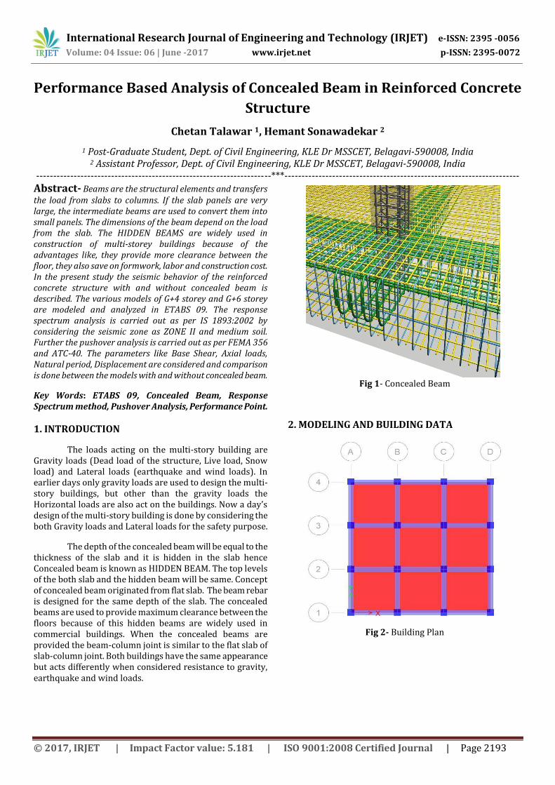
International Research Journal of Engineering and Technology (IRJET) e-ISSN: 2395 -0056 Volume: 04 Issue: 06 | June -2017 www.irjet.net p-ISSN: 2395-0072 © 2017, IRJET | Impact Factor value: 5.181 | ISO 9001:2008 Certified Journal | Page 2193 Performance Based Analysis of Concealed Beam in Reinforced Concrete Structure Chetan Talawar 1 , Hemant Sonawadekar 2 1 Post-Graduate Student, Dept. of Civil Engineering, KLE Dr MSSCET, Belagavi-590008, India 2 Assistant Professor, Dept. of Civil Engineering, KLE Dr MSSCET, Belagavi-590008, India ---------------------------------------------------------------------***--------------------------------------------------------------------- Abstract- Beams are the structural elements and transfers the load from slabs to columns. If the slab panels are very large, the intermediate beams are used to convert them into small panels. The dimensions of the beam depend on the load from the slab. The HIDDEN BEAMS are widely used in construction of multi-storey buildings because of the advantages like, they provide more clearance between the floor, they also save on formwork, labor and construction cost. In the present study the seismic behavior of the reinforced concrete structure with and without concealed beam is described. The various models of G+4 storey and G+6 storey are modeled and analyzed in ETABS 09. The response spectrum analysis is carried out as per IS 1893:2002 by considering the seismic zone as ZONE II and medium soil. Further the pushover analysis is carried out as per FEMA 356 and ATC-40. The parameters like Base Shear, Axial loads, Natural period, Displacement are considered and comparison is done between the models with and without concealed beam. Key Words: ETABS 09, Concealed Beam, Response Spectrum method, Pushover Analysis, Performance Point. 1. INTRODUCTION The loads acting on the multi-story building are Gravity loads (Dead load of the structure, Live load, Snow load) and Lateral loads (earthquake and wind loads). In earlier days only gravity loads are used to design the multi- story buildings, but other than the gravity loads the Horizontal loads are also act on the buildings. Now a day’s design of the multi-story building is done by considering the both Gravity loads and Lateral loads for the safety purpose. The depth of the concealed beam will be equal to the thickness of the slab and it is hidden in the slab hence Concealed beam is known as HIDDEN BEAM. The top levels of the both slab and the hidden beam will be same. Concept of concealed beam originated from flat slab. The beam rebar is designed for the same depth of the slab. The concealed beams are used to provide maximum clearance between the floors because of this hidden beams are widely used in commercial buildings. When the concealed beams are provided the beam-column joint is similar to the flat slab of slab-column joint. Both buildings have the same appearance but acts differently when considered resistance to gravity, earthquake and wind loads. Fig 1- Concealed Beam 2. MODELING AND BUILDING DATA Fig 2- Building Plan
Transcript of Performance Based Analysis of Concealed Beam in Reinforced ... · Performance Based Analysis of...
International Research Journal of Engineering and Technology (IRJET) e-ISSN: 2395 -0056
Volume: 04 Issue: 06 | June -2017 www.irjet.net p-ISSN: 2395-0072
© 2017, IRJET | Impact Factor value: 5.181 | ISO 9001:2008 Certified Journal | Page 2193
Performance Based Analysis of Concealed Beam in Reinforced Concrete
Structure
Chetan Talawar 1, Hemant Sonawadekar 2
1 Post-Graduate Student, Dept. of Civil Engineering, KLE Dr MSSCET, Belagavi-590008, India 2 Assistant Professor, Dept. of Civil Engineering, KLE Dr MSSCET, Belagavi-590008, India
---------------------------------------------------------------------***---------------------------------------------------------------------Abstract- Beams are the structural elements and transfers the load from slabs to columns. If the slab panels are very large, the intermediate beams are used to convert them into small panels. The dimensions of the beam depend on the load from the slab. The HIDDEN BEAMS are widely used in construction of multi-storey buildings because of the advantages like, they provide more clearance between the floor, they also save on formwork, labor and construction cost. In the present study the seismic behavior of the reinforced concrete structure with and without concealed beam is described. The various models of G+4 storey and G+6 storey are modeled and analyzed in ETABS 09. The response spectrum analysis is carried out as per IS 1893:2002 by considering the seismic zone as ZONE II and medium soil. Further the pushover analysis is carried out as per FEMA 356 and ATC-40. The parameters like Base Shear, Axial loads, Natural period, Displacement are considered and comparison is done between the models with and without concealed beam.
Key Words: ETABS 09, Concealed Beam, Response Spectrum method, Pushover Analysis, Performance Point.
1. INTRODUCTION
The loads acting on the multi-story building are Gravity loads (Dead load of the structure, Live load, Snow load) and Lateral loads (earthquake and wind loads). In earlier days only gravity loads are used to design the multi-story buildings, but other than the gravity loads the Horizontal loads are also act on the buildings. Now a day’s design of the multi-story building is done by considering the both Gravity loads and Lateral loads for the safety purpose.
The depth of the concealed beam will be equal to the thickness of the slab and it is hidden in the slab hence Concealed beam is known as HIDDEN BEAM. The top levels of the both slab and the hidden beam will be same. Concept of concealed beam originated from flat slab. The beam rebar is designed for the same depth of the slab. The concealed beams are used to provide maximum clearance between the floors because of this hidden beams are widely used in commercial buildings. When the concealed beams are provided the beam-column joint is similar to the flat slab of slab-column joint. Both buildings have the same appearance but acts differently when considered resistance to gravity, earthquake and wind loads.
Fig 1- Concealed Beam
2. MODELING AND BUILDING DATA
Fig 2- Building Plan
International Research Journal of Engineering and Technology (IRJET) e-ISSN: 2395 -0056
Volume: 04 Issue: 06 | June -2017 www.irjet.net p-ISSN: 2395-0072
© 2017, IRJET | Impact Factor value: 5.181 | ISO 9001:2008 Certified Journal | Page 2194
Fig 3- Building elevation
2.1 Building Data
Plan 9mX9m
Slab panel 3mX3m
Floor Height 3m
Column 450mmX450mm
Normal Beam 300mmX300mm
Concealed Beam 250mmX300mm
Slab thickness 250 mm
Grade of Concrete M20
Grade of Steel Fe 415
Wall Load on Perimeter Beam 13.8 kN/m
Wall Load on Intermediate Beams
9 kN/m
Parapet wall load 3kN/m
Floor Finish(FF) (Assumed) 1kN/m2
Floor Live Load 3kN/m2
Roof Live Load 1.5kN/m2
Type of soil Medium Soil
Type of Structure SMRF
Damping ratio 5% (RC Structure)
Importance Factor (I) 1 (Table 6)
Response Reduction Factor 5 (Table 7)
3 : Analysis of the Building
Response spectrum method is used in the analysis of multi-storey building with and without concealed beam. In response spectrum method, dynamic characteristics are considered. Base shear is calculated by multiplying total seismic weight with acceleration spectrum coefficient. Base shear is calculated according to IS 1893 (Part 1) -2002. RS X – Response Spectrum in X direction, RS Y – Response Spectrum in Y direction.
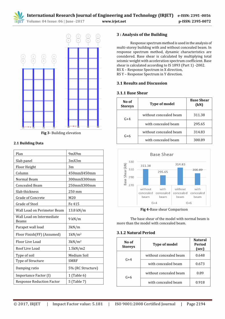
3.1 Results and Discussion 3.1.1 Base Shear
No of Storeys
Type of model Base Shear
(kN)
G+4 without concealed beam 311.38
with concealed beam 295.65
G+6 without concealed beam 314.83
with concealed beam 300.89
Fig 4-Base shear Comparison
The base shear of the model with normal beam is
more than the model with concealed beam.
3.1.2 Natural Period
No of Storeys
Type of model Natural Period (sec)
G+4 without concealed beam 0.648
with concealed beam 0.673
G+6 without concealed beam 0.89
with concealed beam 0.918
International Research Journal of Engineering and Technology (IRJET) e-ISSN: 2395 -0056
Volume: 04 Issue: 06 | June -2017 www.irjet.net p-ISSN: 2395-0072
© 2017, IRJET | Impact Factor value: 5.181 | ISO 9001:2008 Certified Journal | Page 2195
Fig 5- Natural period Comparison
The Natural period of the model with concealed beam is more than the model with the normal beam because the stiffness of the concealed beam model is less than the normal beam model.
3.1.3 Displacement
No of Storeys
Type of model
displacement (mm)
G+4 without concealed beam 6.1
with concealed beam 6.2
G+6 without concealed beam 8.6
with concealed beam 8.8
Fig 6- Displacement Comparison
The depth of the concealed beam is less than that of the normal beam because of this reason the weight of the structure reduces. The stiffness of the whole structure reduces in structure with concealed beam. Hence the displacement of the top storey in models with concealed beam is more than the models with normal beams.
3.2 Pushover Analysis
As the name pushover indicates, push the structure with certain magnitude until it reaches maximum capacity to deform. In this process the load on the structure is gradually increased with certain pre-defined pattern. As the load on the structure increases the yielding of the structure begins and finally gets damaged and failure modes of the structure becomes apparent. The effect of load reversal on the structure during earthquake is analyzed by applying load monotonically and deformation of the structure is estimated with suitable damping. The aim of the pushover analysis is to understand the deformation and cracking of the structure. In pushover analysis the plastic hinges are assigned to the beams and columns at either ends. The hinges should be studied carefully during the collapse mechanism and the performance point may be observed. The hinges are assigned to the beams and columns of the structure as per the guidelines given in ASCE 41. For the beams the flexural hinge (M3) and shear hinge (v2) are assigned at both the ends at relative distance. Similarly, for the columns the combination of axial and flexural hinges (P-M2-M3) are assigned at both the ends with relative distance. At the distance of 0.05 and 0.95, the hinges are assigned to the beams and columns.
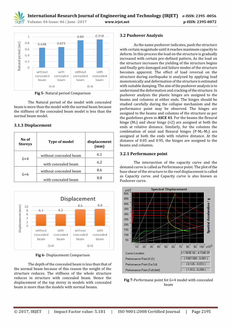
3.2.1 Performance point
The intersection of the capacity curve and the demand curve is called as Performance point. The plot of the base shear of the structure to the roof displacement is called as Capacity curve. and Capacity curve is also known as Pushover curve.
Fig 7-Performane point fot G+4 model with concealed beam
International Research Journal of Engineering and Technology (IRJET) e-ISSN: 2395 -0056
Volume: 04 Issue: 06 | June -2017 www.irjet.net p-ISSN: 2395-0072
© 2017, IRJET | Impact Factor value: 5.181 | ISO 9001:2008 Certified Journal | Page 2196
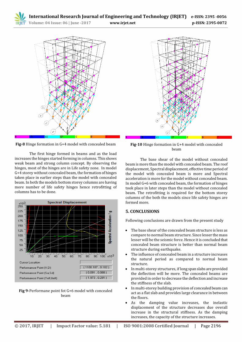
Fig-8 Hinge formation in G+4 model with concealed beam
The first hinge formed in beams and as the load increases the hinges started forming in columns. This shows weak beam and strong column concept. By observing the hinges, most of the hinges are in Life safety zone. In model G+4 storey without concealed beam, the formation of hinges taken place in earlier steps than the model with concealed beam. In both the models bottom storey columns are having more number of life safety hinges hence retrofitting of columns has to be done.
Fig 9-Performane point fot G+6 model with concealed beam
Fig-10 Hinge formation in G+4 model with concealed beam
The base shear of the model without concealed beam is more than the model with concealed beam. The roof displacement, Spectral displacement, effective time period of the model with concealed beam is more and Spectral acceleration is more for the model without concealed beam. In model G+6 with concealed beam, the formation of hinges took place in later steps than the model without concealed beam. The retrofitting is required for the bottom storey columns of the both the models since life safety hinges are formed more.
5. CONCLUSIONS
Following conclusions are drawn from the present study The base shear of the concealed beam structure is less as
compare to normal beam structure. Since lesser the mass lesser will be the seismic force. Hence it is concluded that concealed beam structure is better than normal beam structure during earthquake.
The influence of concealed beam in a structure increases the natural period as compared to normal beam structure.
In multi-storey structures, if long span slabs are provided the deflection will be more. The concealed beams are provided in order to decrease the deflection and increase the stiffness of the slab.
In multi-storey building provision of concealed beam can act as a flat slab and provides large clearance in between the floors.
As the damping value increases, the inelastic displacement of the structure decreases due overall increase in the structural stiffness. As the damping increases, the capacity of the structure increases.

International Research Journal of Engineering and Technology (IRJET) e-ISSN: 2395 -0056
Volume: 04 Issue: 06 | June -2017 www.irjet.net p-ISSN: 2395-0072
© 2017, IRJET | Impact Factor value: 5.181 | ISO 9001:2008 Certified Journal | Page 2197
The more number of life safety (LS) hinges are formed in model with concealed beams as compared to model with normal beams. hence performance of the model with concealed beams is better than model with normal beams.
ACKNOWLEDGEMENT
The authors would like to thank Shri S. C. Metagud Chairman Governing council, K.L.E.M.S.S.C.ET and Dr. Basavaraj G. Katageri principal of K.L.E.M.S.S.C.ET, Belagavi for their kind support and providing good infrastructure. The authors are grateful to Prof. (Smt) Bharati Chiniwalar, Head of Civil Department, for encouragement and support.
REFERENCES Akash.C. Arakere, Tejas D. Doshi, “Comparison of Multi-
Storey Building with Normal Beams and Concealed Beams”, International Research Journal of Engineering and Technology (IRJET) e-ISSN: 2395 -0056, | June-2015
Samir H. Riyaj Awad, “Performance based analysis of Hidden Beams in Reinforced Concrete Structure”, An-Najah National University, Nablus, Palestine.
Samir H. Helou, Munther M. Diab, “Slabs with Hidden Beams”, An-Najah National University, Nablus, Palestine.
Navyashree K, Sahana T.S, “Use of flat slabs in multi-storey commercial buildingsituated in high seismic zone”, International Journal of Research in Engineering
and Technology, eISSN: 2319-1163, August, 2014.
M. Altus ERBERIK, Amr S. ELNASHAI, “Vulnerability analysis of flat slab structures”, 13th World Conference on Earthquake Engineering, August, 2014.
Sumit Pahwa, Vivek Tiwari and Madhavi Prajapati, “Comparative Study of Flat
Slab with Old Traditional Two-way slab”, International Journal of Latest Trends
Federal Emergency Management Agency, FEMA-356: Pre standard and Commentary for the Seismic Rehabilitation of Buildings, 2000: Washington DC.
Federal Emergency Management Agency, FEMA-440: Improvement of Non-linear Static Seismic Analysis Procedures, June-2005: Washington DC.
ATC -40, ‘Seismic Evaluation and Retrofit of Concrete Buildings’, Vol. 1&2, Applied Technology Council, California, 1996
BIOGRAPHIES
Chetan Talawar Post-Graduate Student, Department of Civil Engineering, K.L.E. Dr.M.S.Sheshigiri College of Engineering and Technology, Belagavi, India- 590008
Prof. Hemant Sonawadekar M.Tech (Structural Engineering), B.E (Civil), Assistant Professor, Department of Civil Engineering, K.L.E. Dr.M.S.Sheshigiri College of Engineering and Technology, Belagavi, India- 50008