PDF (597 KB) - IOPscience
11
Journal of Physics: Conference Series OPEN ACCESS Innovative unmanned airship structural analysis: Dual-hull and exoskeletal configurations To cite this article: A Cappadona et al 2009 J. Phys.: Conf. Ser. 181 012097 View the article online for updates and enhancements. You may also like Study of the features of the characteristics of a hybrid airship turn S F Borodkin, M A Kiselev and M V Shkurin - Turbulence characteristics of large factory building and its influence on airship transport process Yuan Liu, Hu Ye, Yongdong Zhang et al. - Application of magnus effect and lift blade in high altitude wind power Honglin Zhang, Hongwei Yang, Xiaoli Ma et al. - Recent citations Uncertainty Analysis of a Dynamic Model of a Novel Remotely Piloted Airship William Becker et al - This content was downloaded from IP address 121.162.232.91 on 21/12/2021 at 12:15
Transcript of PDF (597 KB) - IOPscience

Journal of Physics Conference Series
OPEN ACCESS
Innovative unmanned airship structural analysisDual-hull and exoskeletal configurationsTo cite this article A Cappadona et al 2009 J Phys Conf Ser 181 012097
View the article online for updates and enhancements
You may also likeStudy of the features of the characteristicsof a hybrid airship turnS F Borodkin M A Kiselev and M VShkurin
-
Turbulence characteristics of large factorybuilding and its influence on airshiptransport processYuan Liu Hu Ye Yongdong Zhang et al
-
Application of magnus effect and lift bladein high altitude wind powerHonglin Zhang Hongwei Yang Xiaoli Maet al
-
Recent citationsUncertainty Analysis of a Dynamic Modelof a Novel Remotely Piloted AirshipWilliam Becker et al
-
This content was downloaded from IP address 12116223291 on 21122021 at 1215
Innovative Unmanned Airship Structural Analysis Dual-Hull and Exoskeletal Configurations
Alessio Cappadona1 Roberto Lecca1 Matteo Vazzola1 Piero Gili1 Pierangelo Farina2 Cecilia Surace3 1Politecnico di Torino Dept of Aeronautical and Space Engineering corso Duca degli Abruzzi 24 Torino Italy
2BLUE Engineering Via Albenga 98 Rivoli (TO) Italy
3Politecnico di Torino Dept of Structural and Geotechnical Engineering corso Duca degli Abruzzi 24 Torino Italy
ceciliasuracepolitoit
Abstract The research study described concerns the design and development of an innovative airship concept which is remotely-controlled and intended to be used for monitoring surveillance exploration and reconnaissance missions Two potential structural configurations have been analysed the first consists of a dual-hull configuration characterised by the presence of a primary support structure flanked by the two inflated sections held to the structure by appropriated bindings The second is an exoskeletal configuration which features a single inflated section incorporating two separate elements held internally by a system of ribs The final aim of this study is to analyse both configurations to determine the most appropriate solution in terms of performance and cost
1 Introduction In recent years there has been a considerable surge of interest in the development of unmanned aerial vehicles for applications both in the civilian and military sectors Radio-controlled airships represent the most suitable solution for missions of surveillance and exploration at low altitudes and low velocities Furthermore airships are also being considered for radio or television platforms radio relays and specialist scientific applications Due to the nature of their propulsion they are practically silent non-polluting ecological and hence suited for employment in environmental and oceanographic fields as well as for use in atmospheric analysis and nocturnal surveillance
Such ldquolighter-than-airrdquo platforms combine the advantages of the capability of vertical takeoff with the feasibility of extensive flight times over a range of velocities and altitudes Moreover in comparison with helicopters for example the absence of rotors reduces the cost of structural design and the effects of the resulting substantial vibration on the payload (likely to be television cameras or surveillance equipment) Thus overall due to their inherent characteristics regarding performance and safety airships can be used effectively in commercial civil and military applications
7th International Conference on Modern Practice in Stress and Vibration Analysis IOP PublishingJournal of Physics Conference Series 181 (2009) 012097 doi1010881742-65961811012097
ccopy 2009 IOP Publishing Ltd 1
For the applications described above it is conceivable to employ a classical airship design however such designs have intrinsic weaknesses ndash such as problems with control at low velocities in particular during landing and takeoff and in adverse weather conditions Hence it was proposed to design a new type of radio-controlled lighter-than-air platform which is novel in terms of its unconventional shape and control system
Conventional airships are manoeuvred (in addition to a possible longitudinal orientation of thrusting propellers) by aerodynamic surfaces that have one part fixed and one part mobile The construction of this new design is distinctly different to that of a classical configuration in that it is based on a structure of two adjacent hulls separated by a central plane which has both a structural function and serves to contain or support the payload and power unit The dual-hull design (named ldquoElettra Twin Flyers (ETF)rdquo) has the important distinction of a reduced lateral cross-sectional area (hence reduced sensitivity to cross winds) for a similar volume of gas thus still retaining comparative buoyancy The airship features ballonets inside each envelope which can be inflated and deflated with air during descent and ascent respectively The landing gear is comprised of a system of legs The features described are represented in Figure 1
Figure 1 The design of Elettra Twin Flyers With appropriate rotation and variation of the thruster forces generated automatically through the
control system this configuration enables rotation around three axes and translation in three directions Furthermore it is possible to remain hovering with the prow (the front of the ship corresponding to the positive x-direction as illustrated in figure 1) orientated in any direction with winds incident at any angle During hovering altitude is maintained by the helium and the propellers orientated along the vertical axis while during forward movement additional aerodynamic lift is also generated as a result of air-flow over the hulls with suitable angle of attach As such the complete elimination of aerodynamic control surfaces not only increases manoeuvrability at low velocities but eliminates a source of disturbance during operation in adverse weather conditions An obvious consequence of this approach is the need for higher power required for manoeuvres and a reduction in manoeuvrability with increasing velocity when compared to airships of conventional design However for aircraft used primarily for surveillance applications this is not thought to represent a particular problem
The current design is an evolution of previous designs whereas the concept behind the control system is identical comprising a set of 8 or 10 propellers of which 2 or 4 are fixed and 4 or 8 are
7th International Conference on Modern Practice in Stress and Vibration Analysis IOP PublishingJournal of Physics Conference Series 181 (2009) 012097 doi1010881742-65961811012097
2
manoeuvrable Similar to previous designs with the new ETF06 there are no movable aerodynamic control surfaces
Aside from the use of electric motors low environmental impact is guaranteed by the chosen power system ndash hydrogen fuel cells ndash and auxiliary batteries or supercapacitors to cope with energy peaks resulting from abrupt manoeuvres
After construction of the flight simulator and a working (albeit simplified) ldquodemonstratorrdquo airship two more advanced designs were proposed regarding the structure of the prototype They are the result of a natural evolution of the demonstrator and will use the same control strategy The two alternative solutions are as follows
bull The first is a direct derivation of the demonstrator ndash the ldquodual-hullrdquo solution This is characterised by a main load-bearing structure to which are attached on either side the two gas envelopes attached by arms of an elongated S-shape
bull The second solution is distinctly different from the demonstrator above all because unlike the latter it is a rigid structure ndash this is known as the ldquoexoskeletalrdquo design It features a single hull formed from the union of two parallel hulls supported internally by a system of structural ribs
The structural development of both designs will be driven by a series of structural analyses the object being to arrive at a solution with minimum weight minimum volume maximum safety and minimum cost
2 Dual-Hull Configuration The dual-hull configuration (Figure 2) is the classic design of two hulls separated by a central
structure The nacelle (the compartment in which the payload power supply and suchlike are located) is positioned beneath the line of contact between the two hulls enabling television cameras if installed to be angled and point downwards without any visual obstructions additionally it reduces the volume of the structure Two large vertical propellers are positioned both at the prow and stern Eight further propellers are used for orientation however these could be reduced to four the minimum number required for full manoeuvrability The connecting structure is a central tube running in the longitudinal direction between one supporting arm and the other ndash these arms are used to hold the propellers in position and are hence rigid
The design of the various solutions was performed using the CAD package CATIA V5 In total three solutions were investigated however the relative dimensions of the structure remained unchanged ndash only the total length was varied between 25 34 and 36 metres Throughout the design process the implications of construction were considered in such a way so as not to render the structure prohibitively expensive Hence components were designed to have symmetry ndash the substantial size of the various components does not permit entire pieces to be manufactured at once given the limitations of the dimensions of the available moulds An additional advantage of symmetry is that the number of moulds required is reduced with a subsequent reduction in production cost
The structure (Figure 3) is comprised of a central longitudinal member to which are connected four supporting strips or arms of an elongated S-shape running along the surface of the hulls and three septa (dividing structures) which support the nacelle Inside the latter the payload is contained which may include a range of video and photographic devices equipment relating to mapping of terrain and the power unit Both the septa and the supporting arms are attached to belts encompassing the hulls to prevent the membranes from assuming the typical banana-shape which would otherwise occur
The central tube is the part to which all the perpendicular components are attached ndash the supporting arms and the septa Its length is proportional to the sum of the two semi-axes of the ellipses that constitute the hulls (around 06 times the total length) it must be sufficiently long to allow the supporting arms to encompass the hulls Additionally the tube supports the two vertical propellers at either extremity
The supporting arms represent the most critical part of the design since due to their long and slender shape are likely to experience the most severe deflections of the entire structure Their function is to impede the hulls from changing shape as well as being points of attachment for the eight
7th International Conference on Modern Practice in Stress and Vibration Analysis IOP PublishingJournal of Physics Conference Series 181 (2009) 012097 doi1010881742-65961811012097
3
longitudinal manoeuvring propellers It is critical that these components be resistant to excessive deformation the control of the airship depends completely on the positioning of the propellers ndash if these are displaced significantly there would be problems in manoeuvring
Figure 2 Dual-hull configuration Figure 3 Illustration of structural assembly
The central septa has two functions The first regards the hulls ndash together with the supporting arms
they keep the membranes in position with the aid of straps encompassing the membranes The second is to support the nacelle below In the model created for the simulation in MSCNASTRAN the nacelle was assumed to be positioned hanging from the septa in the space between the two hulls the connection was simulated with rigid elements As with the supporting arms the septa were intentionally designed to have planes of symmetry ndash in fact they exhibit symmetry in every plane As such due to their symmetrical nature it may no longer be necessary to suspend the nacelle rather simply attach it to the septa
The dimensions of the hulls were subjected to careful aerodynamic investigation such that the air resistance due to its shape was as low as possible even at low velocities The slenderness ratio of the hulls (ratio of length to radius) is the most important geometric parameter in determining the hull drag The shape of the hull is constructed of two half-ellipses one having its major axis equal to a third of the total length of the airship the second having a major axis of the remaining two-thirds of the length The minor axes of both clearly are the same and equal to approximately one-eighth of the total length Hence it is a solid of revolution whose dimensions are fundamental to subsequent calculations ndash the volume of helium that can be contained (and hence the aerostatic lift) and the surface area of the hulls which is necessary to calculate the mass
3 Exoskeletal Configuration The second configuration is that of the exoskeletal design (Figure 4) formed by drawing together and uniting the two hulls The principal advantage is that for an equivalent size there is an increase of around 20 in the volume available for helium thus in theory it is possible to increase the payload or decrease the length of the structure In reality it is necessary to evaluate the mass of the structure of this second solution which is found to be greater than the dual-hull design of the same length There are four vertical propellers positioned at the prow and the stern or along the sides of the airship
The structure of the exoskeletal design is geodesic and constructed of eight ldquoribsrdquo of a T-section (Figure 5) Thus the propellers can be attached in more different positions than compared to the dual-hull Despite this the number of propellers was reduced for eight to four ndash two positioned on top of the airship and two on the underside all aligned with the longitudinal axis In this case the nacelle is also positioned on the underside
In this design the envelope is no longer a single entity instead it is divided into an internal membrane containing the helium and an outer layer purely to retain the shape of the structure
7th International Conference on Modern Practice in Stress and Vibration Analysis IOP PublishingJournal of Physics Conference Series 181 (2009) 012097 doi1010881742-65961811012097
4
There are two main causes of deformation in the exoskeletal design the buoyancy that is acting upwards on the upper ldquospinerdquo of the airship and the weight of the nacelle that acts downwards on the belly The result is a dilation of the structure along the vertical direction resulting in deformations greater than one metre The solution to this problem was the application of a series of restraining cables in the vertical-longitudinal plane with a consequent albeit small increase in mass (around 10kg) A small complication then arises from a manufacturing point of view concerning the attachment of these cables to the inside of the membrane given that any attachments must be impermeable to helium
An additional increase of weight is caused by the necessity of having a structural network of a sufficient density so as not to allow the membrane to dilate between bracing cables ndash this would cause problems from an aesthetic and aerodynamic perspective
Figure 4 Exoskeletal configuration Figure 5 Illustration of structural assembly
4 Cost Function Definition To select the best solution a cost function was introduced that accounted for a number of design criteria such that a more desirable design would produce a lower cost index Each criterion was weighted according to its perceived importance to give an objective view of the suitability of the design The following factors were considered bull The dimensions the cost of this parameter is considered to be linearly dependent and given a
medium-high importance bull The weight evaluated in a similar manner to the dimensions but with a medium-low importance bull Sensitivity to wind this is an aerodynamic consideration evaluated in terms of aerodynamic
derivatives of stability The cost is given a quadratic relationship and a high importance bull The handling in mid-air and the positioning of the payload since in both cases it is difficult to
define a parameter that accurately represents these criteria they were judged quantitatively and assigned a medium importance
bull Cost of purchase and running costs a linear parameter with a medium-high importance bull Reliability service life and maintenance (cost and duration of maintenance) these are parameters
that can be considered similar if not equal for both solutions (or at least are subject to discretion and the design objectives of the project having clear cost implications) They have linearly-increasing costs and have been attributed a medium-high importance
7th International Conference on Modern Practice in Stress and Vibration Analysis IOP PublishingJournal of Physics Conference Series 181 (2009) 012097 doi1010881742-65961811012097
5
5 Material Selection In both cases the material was chosen to be a multilayered composite of carbonepoxy arranged in four layers [045-4590] The mechanical properties are reported in [5] [6]
A preliminary series of analyses were performed using simply a thickness of 2 or 25mm on all the surfaces designed with the software CATIA Given the unsatisfactory results obtained it was subsequently decided to increase the moment of inertia of the section by substituting the material with one of a sandwich structure The sandwich structure comprised two 16mm sections of the four layers of the composite described above in the same arrangement either side of a central 25mm lightweight orthotropic honeycomb core The nature of the layup resulted in macroscopic quasi-isotropic material properties All materials in the model were assumed to be linear elastic and homogeneous The honeycomb material had elastic moduli of 121MPa and 100MPa in the x and y-directions respectively with a density of 50gdm3 In comparison the composite had elastic moduli of 157GPa in the direction of the fibres and 8GPa orthogonal to them
6 External Load Definition The loads considered acting on the structure are from two sources ndash those resulting from the mass of the structure and the forces from the propellers The propeller forces were simulated as point forces along the axis of rotation of the motors The magnitude and direction of these forces was varied to simulate the gamut of possible manoeuvres and in particular the loading cases which resulted in the most severe deflections of the structure
The buoyancy was applied to the upper part of the structure in the case of the exoskeletal design and to the septa on in the simulation of the dual-hull design The value of the buoyancy was calculated based on the volume of helium and applied in discrete sections across the structure This approach was necessary at this stage in the analysis since the interactions between the helium envelopes and the structure were not explicitly modelled
The payload and the avionics were modelled as added masses that were distributed over the lower part of the cargo bay The landing gear was considered in a similar manner The mass of the envelopes was distributed over the entire structure The aerodynamic forces were not considered in the analysis ndash they would require a distributed pressure over the surfaces of the model However they are not thought to contribute significantly to the loading In order to properly consider these effects a coupled fluid-structure interaction model would be required The inertial loads on the structure are accounted for using the option of inertia relief that is available in Patran ndash this is detailed in the following paragraph All loads on the structure were considered to be static ndash that is inertial effects during loading were not accounted for This is justified by the slow application of pressure and motor forces in reality
7 Structural Analysis The structural analysis was performed using two software packages ndash firstly the pre-processing in MSCPatran and then the structural solution using MSCNastran A major problem in the simulation of both structures was that the software required that both models were constrained in some manner otherwise the stiffness matrix would become singular on inversion To avoid this problem it was decided to use the method of inertia relief Inertia relief is a command in MSCPatran that allows the simulation of an unconstrained structure under linear static conditions This approach avoids the problem of unrealistic stress concentrations which would arise in the use of conventional constraints Typical applications of this method include the simulation of aircraft in flight satellites in space or as in this situation an airship under various loading conditions Under inertia relief the structure is unconstrained but the inertia of the structure resists the loading in such a way that the entire structure is in a state of equilibrium
7th International Conference on Modern Practice in Stress and Vibration Analysis IOP PublishingJournal of Physics Conference Series 181 (2009) 012097 doi1010881742-65961811012097
6
In a simulation using inertia relief the analyst selects a point in the structure to be a ldquosupportrdquo The FEA solver then applies a distribution of uniform acceleration such that the induced inertial forces and the design loads (pressure and forces) produce a reaction force of zero magnitude on the same support thus resulting in a system of forces in equilibrium When the ldquoinertia reliefrdquo option is invoked in a static analysis MSCNASTRAN calculates the resultant force in all directions and thus the field of acceleration that must be applied to the entire structure such that it will be in equilibrium
8 Results and Comparison of the Two Models The structural design in this project was assisted by a number of structural analyses which have allowed the calculation of member thicknesses the geometry and hence the total mass of the proposed structure These values combined with information regarding the loads on the structure were compared with the aerostatic lift generated from the buoyancy of the helium The objective was to ascertain the necessary length of the airship ndash it was found that for the exoskeletal design required a minimum length of 32m while the dual-hull could be no less than 36m Once the required length was established such that the lift balanced the weight a structural comparison was performed between the two solutions 81 Displacements Table 1 shows the results from the two models under a variety of loading situations
Exoskeleton Double-hull LOAD CASES Displacements[m] Displacements[m] Hovering 0132 0336 Mot Long 1 0147 0354 Mot Long 2 0149 0340 Mot Long 3 0147 0971 Mot Long 4 0144 0752 Mot Vert 1 0182 0336 Mot Vert 2 1150 0344 Mot Vert 3 0147 0384 Mot Vert 4 0144 Parking 1 0533 Parking 2 0773 0307
Table 1
As can be seen in the above table both models exhibit displacements that are within acceptable limits of 500mm (this value was verified using the ETF simulator by updating the propellers positions in the situation with the structure deformed in order to check that the airship maintains complete controllability) for the majority of load cases However to arrive at these results it was necessary to modify the designs to some extent For the exoskeletal model bracing cables were used in the vertical direction in such a way as to attach the upper surface of the airship to its equatorial rib thus impeding the structure from deforming in the vertical sense this alteration significantly reduced displacement Regarding the dual-hull model restraining straps were simulated that joined the top and bottom ends of the supporting arms to observe whether the displacements would still be as substantial The results showed that displacements relative to the two S-shaped arms were notably decreased For the dual-hull model the simulation was not entirely realistic since the hulls themselves were not included thus it was not possible to investigate the manner in which the restraining straps interacted with the membrane and the resultant stresses on both bodies
7th International Conference on Modern Practice in Stress and Vibration Analysis IOP PublishingJournal of Physics Conference Series 181 (2009) 012097 doi1010881742-65961811012097
7
82 Stress Analysis In comparison it was found that the results from the two models were quite similar The dual-hull design performed particularly well due to its optimum distribution of stress which did not surpass 300MPa at any point in the structure Conversely the exoskeletal solution yielded critical stresses under forces from propellers in the vertical axis when the structure was completely supported by the ground (the takeoff situation) In reality these comparisons were drawn without considering the alleviating effect of the buoyancy which reduces the load by 5 in operational conditions During construction however forces from propellers and buoyancy are not present so the structure could indeed experience the magnitudes of stress calculated
Table 2 shows the results from the inertia relief analysis for various loading situations
Exoskeleton Double-hull LOAD CASES Stress[MPa] Stress[MPa]
Hovering 353 144 Mot Long 1 367 193 Mot Long 2 346 269 Mot Long 3 354 280 Mot Long 4 364 264 Mot Vert 1 375 133 Mot Vert 2 354 155 Mot Vert 3 369 163 Mot Vert 4 1120
Parking 1 435 Parking 2 810 137
Table 2
The problem of the magnitude of the stress can be resolved by increasing the thickness of the material however this will of course increase the weight of the structure and cause further problems with the production transportation and construction 83 Aerodynamics Numerical analyses were performed of turbulent incompressible flow on both models [10] which revealed that there was a distinct advantage from an aerodynamic point of view for the exoskeletal design in particular in the ldquocross-windrdquo situation (hovering with air flow perpendicular to the axis of the ship as shown in Figure 6) Conversely the presence of the two hulls actually accentuated the strength of vortices since there is additional flow separation between the two hulls as well as the wake behind the entire structure Aside from the increase in drag this could be dangerous if the frequency of aerodynamic excitation is coincident with the natural modes of the structure Such a coupling could not only cause damage to the structure but also in extreme situations may result in structural failure Due to this fact and additional aerodynamic considerations the exoskeletal design is considered to be superior
7th International Conference on Modern Practice in Stress and Vibration Analysis IOP PublishingJournal of Physics Conference Series 181 (2009) 012097 doi1010881742-65961811012097
8
Figure 6 Air flow perpendicular to the axis of the airship 84 Costing A further comparison can be drawn from a construction point of view ndash it should be noted that for the dual-hull solution only the gas envelopes are 36m long the entire structure does not surpass 22m in length This is surely a point in favour of this design ndash the number of pieces to assemble and disassemble is considerably less than the alternative solution which would also make transportation less expensive than the exoskeletal design Cost coefficients were evaluated for each design taking into account a number of factors the number of components the number of moulds used the number of connections and fixings the difficulty of construction and the quantity of material necessary A comparison between the two revealed that the dual-hull design offered a saving of around 15-20 85 Cost function consideration Of the other parameters in the cost function values are given to the greatest accuracy that can be permitted in the early stages of the design or neglected from this first analysis due to the difficulty of determining them at this point The parameters that have been examined above are thought in any case to be most significant and are hence the basis for the following conclusions 9 Conclusions In summary the cost function reveals that the structural and financial advantages of the dual-hull design are roughly balanced by the aerodynamic benefits of the exoskeletal design As such a third design (shown in Figure 7) is in the development stage which will unite the aerodynamic advantages of the exoskeletal design with the construction benefits of the dual-hull Illustrated are the internal cables (for structural loads) and supports (to maintain the position and form of the membrane) together with the load-bay (for the avionics power systems payload etc) A robust longitudinal keel has been introduced this being the sole rigid structural element on which act all the loads in the system including propulsive and aerodynamic forces and buoyancy Instead the command and control systems are to remain unchanged
7th International Conference on Modern Practice in Stress and Vibration Analysis IOP PublishingJournal of Physics Conference Series 181 (2009) 012097 doi1010881742-65961811012097
9
Figure 7 The new structural solution
Acknowledgements The authors would like to thank Will Backer for his assistance in the writing of this article The activity presented in the article is part of the project entitled Innovative solutions for control systems electric plant materials and technologies for a non-conventional remotely-piloted aircraft funded by the Piedmont Region
References [1] Elfes A Bueno SS Bergerman M Ramos JJrG ldquoA Semi-Autonomous Robotic Airship for
Environmental Monitoring Missionsrdquo Proceedings of the 1998 IEEE International Conference on Robotics amp Automation Leuven Belgium May 1998 pp 3449-3455
[2] Zaugg DA Arnold DV Jensen MA ldquoOcean Surface and Landside Probing with a Scanning Radar Altimeterrdquo Proceedings of the 2000 International Geoscience and Remote Sensing Symposium vol 1 2000 pp 120-120
[3] Hain JHW ldquoLighter-than-air Platforms (Blims and Aerostats) for Oceanographic and Atmospheric Research and Monitoringrdquo Proceedings of the Oceans 2000 MTS IEEE Conference and Exhibition vol 3 2000 pp 1933-1936
[4] Cappadona A ldquoAnalisi Strutturale su Dirigibile non Convenzionale a Controllo Remoto Configurazione Esoscheletrordquo MSc Thesis October 2008
[5] Lecca R ldquoAnalisi Strutturale su Dirigibile non Convenzionale a Controllo Remoto Configurazione Bifusordquo MSc Thesis October 2008
[6] Battipede M Lando M Gili PA and Vercesi P ldquoPeculiar Performance of a New Lighter-Than-Air Platform for Monitoringrdquo AIAA 4th ATIO Forum September 2004 Chicago Illinois
[7] CATIA V5R18 Computer Aided Design (CAD) software Dassault Systems France [8] MSC Nastran 2005 Finite element method (FEM) software MSC Software USA [9] MSC Patran 2005 FEM pre and post-processing software MSC Software USA [10] Visone M (062008) ETF06 Airship Aerodynamic Investigations
7th International Conference on Modern Practice in Stress and Vibration Analysis IOP PublishingJournal of Physics Conference Series 181 (2009) 012097 doi1010881742-65961811012097
10
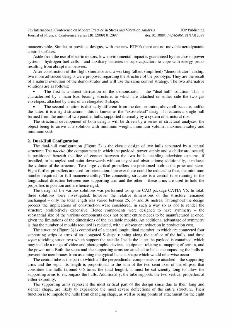
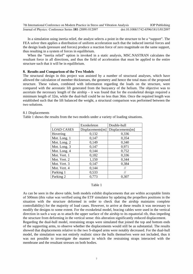