PDF (928 KB) - IOPscience
13
Journal of Instrumentation OPEN ACCESS RCU2 — The ALICE TPC readout electronics consolidation for Run2 To cite this article: J Alme et al 2013 JINST 8 C12032 View the article online for updates and enhancements. You may also like Radiation tolerance studies using fault injection on the Readout Control FPGA design of the ALICE TPC detector J Alme, D Fehlker, C Lippmann et al. - Ion backflow studies with a triple-GEM stack with increasing hole pitch H. Natal da Luz, P. Bhattacharya, L.A.S. Filho et al. - The ALICE TPC: Status and perspectives Hans Rudolf Schmidt and (forthe Alice Experiment) - This content was downloaded from IP address 126.74.158.161 on 26/03/2022 at 14:54
Transcript of PDF (928 KB) - IOPscience

Journal of Instrumentation
OPEN ACCESS
RCU2 mdash The ALICE TPC readout electronicsconsolidation for Run2To cite this article J Alme et al 2013 JINST 8 C12032
View the article online for updates and enhancements
You may also likeRadiation tolerance studies using faultinjection on the Readout Control FPGAdesign of the ALICE TPC detectorJ Alme D Fehlker C Lippmann et al
-
Ion backflow studies with a triple-GEMstack with increasing hole pitchH Natal da Luz P Bhattacharya LASFilho et al
-
The ALICE TPC Status and perspectivesHans Rudolf Schmidt and (forthe AliceExperiment)
-
This content was downloaded from IP address 12674158161 on 26032022 at 1454
2013 JINST 8 C12032
PUBLISHED BY IOP PUBLISHING FOR SISSA MEDIALAB
RECEIVED October 31 2013ACCEPTED December 5 2013
PUBLISHED December 19 2013
TOPICAL WORKSHOP ON ELECTRONICS FOR PARTICLE PHYSICS 201323ndash27 SEPTEMBER 2013PERUGIA ITALY
RCU2 mdash The ALICE TPC readout electronicsconsolidation for Run2
J Almea1 T Alt j L Bratrud f P Christianseni F Costae E Davidh T Gunjik
T Kissh R Langoslashy f J Lien f C Lippmannd A Oskarssoni A Ur Rehmang
K Roslashedb D Rohrichc A Tarantola j C Torgersenc I Nikolai Torsvikc K Ullalandc
A Velurec S Yangc C Zhaob H Appelshauser j and L Ostermani2
aBergen University College PO Box 7030 NO-5020 Bergen NorwaybUniversity of Oslo PO Box 1048 Blindern NO-0316 Oslo NorwaycUniversity of Bergen PO Box 7800 NO-5020 Bergen NorwaydGSI Helmholtzzentrum fur SchwerionenforschungPlanckstr 1 D-64291 Darmstadt Germany
eCERN CH-1211 Geneve 23 Switzerlandf Vestfold University College Postboks 2243 NO-3103 Toslashnsberg NorwaygCOMSATS Institute of Information TechnologyPark Road Chak Shahzad Islamabad Pakistan
hCerntech Petzval J u 44 H-1119 Budapest HungaryiUniversity of Lund Box 117 221 00 LUND SwedenjGoethe University FrankfurtSenckenberganlage 31 60325 Frankfurt am Main Germany
kUniversity of Tokyo 7-3-1 Hongo Bunkyo-ku Tokyo 113-0033 Japan
E-mail johanalmehibno
ABSTRACT This paper presents the solution for optimization of the ALICE TPC readout for run-ning at full energy in the Run2 period after 2014 For the data taking with heavy ion beams an eventreadout rate of 400 Hz with a low dead time is envisaged for the ALICE central barrel detectorsduring these three years A new component the Readout Control Unit 2 (RCU2) is being designedto increase the present readout rate by a factor of up to 26 The immunity to radiation inducederrors will also be significantly improved by the new design
KEYWORDS Electronic detector readout concepts (gas liquid) Front-end electronics for detectorreadout Data acquisition concepts Digital electronic circuits
1For the ALICE TPC collaboration2Corresponding author
ccopy CERN 2013 for the benefit of the ALICE collaboration published under the termsof the Creative Commons Attribution 30 License by IOP Publishing Ltd and Sissa
Medialab srl Any further distribution of this work must maintain attribution to the author(s) and thepublished articlersquos title journal citation and DOI
doi1010881748-0221812C12032
2013 JINST 8 C12032
Contents
1 Introduction 1
2 Present TPC readout electronics 221 Motivation for the RCU2 upgrade 3
3 Alternative LS1 upgrade proposals 4
4 RCU2 441 GTL backplane design 542 RCU2 hardware design 543 Radiation monitor 6
5 RCU2 FPGA design 6
6 RCU2 DCS software 8
7 Radiation tolerance measures and irradiation campaigns 8
8 Outlook and conclusions 9
1 Introduction
The Large Hadron Collider (LHC) accelerates protons and lead ions close to the speed of light andcollides them inside the four experimental areas along the beamline One of the LHC experimentsis A Large Ion Collider Experiment (ALICE) [1]
The ALICE detector comprises several sub-detectors of which one is the Time ProjectionChamber (TPC) [2] The TPC detector is the main tracking detector of ALICE The end plates onboth sides of the TPC barrel are populated with 557 568 readout pads The TPC readout electronicsis located directly behind the two detector end plates
Following a successful running period from November 2009 to January 2013 (Run1) [3] theLHC is currently shut down for maintenance and preparation for even higher energies and lumi-nosities This period named Long Shutdown 1 (LS1) lasts end of 2014
The next running period (Run2) is between 2015 and 2018 In this period a peak luminosity upto 4x1027 cm-2s-1 can be expected for Pb-Pb collisions with centre-of-mass energy of 55 TeV pernucleon pair As a comparison in the heavy ion run in 2011 the luminosity reached 1026 cm-2s-1 [3]The envisaged luminosities for Run2 correspond to interaction rates from 8 to 30 kHz To get max-imum benefit from the delivered luminosities the most attractive data taking scenario for ALICEforesees data taking rates of at least a factor two faster than what can be achieved with the cur-rent TPC readout electronics For a trigger mix containing central semi-central minimum bias
ndash 1 ndash
2013 JINST 8 C12032
RCU1
TTC (optic link)
MonitorControl (Ethernet)
DDL link (optic ndash 1280 Gbs)
Xilinx Virtex-2pro
Actel FPGA
FEC
s ndash
Bra
nch
AFE
Cs
ndash B
ran
ch B
GTL
bu
s br
anch
AG
TL b
us
bran
ch B
DCS board
AlteraFPGA
ActelFPGA
SIU card
Figure 1 Sketch of the present TPC readout electronics with the RCU1
calorimeter and Transition Radiation Detector (TRD) triggers an event readout rate of at least400 Hz is envisaged for the ALICE central barrel detectors while keeping a reasonably low deadfraction (busy time) In comparison the maximum achieved readout rate for the same trigger mixof the current TPC readout electronics has been measured to be about 320 Hz (in this case with highdead fraction) The higher luminosities for Run2 will also lead to a 40 increase in the event sizessince the number of tracks per interaction will be higher The maximum event size for a centralevent in Run1 is 65 MB for Run2 a corresponding event will produce 90 MB of data
This paper presents the RCU2 which is the replacement of the present Readout Control UnitIt is currently being developed in order to provide a readout system capable to achieve the discussedperformance requirements
2 Present TPC readout electronics
A sketch of the present TPC readout electronics [2] is shown in figure 1 and consist of a ReadoutControl Unit (RCU) that connects to between 18 and 25 Front End Cards (FECs) depending onthe radial position of the RCU in the TPC barrel The radial direction is divided into 6 readoutpartitions with one RCU each The connectivity between the RCU and the FECs is implementedusing two branches of a multidrop parallel Gunning Transistor Logic (GTL) bus with a bandwidth16 Gbps The FEC itself has 128 analog input channels with each input channel corresponding toa single detector pad on the TPC detector
The present RCU from here on referred to as RCU1 consists of a motherboard with two at-tached mezzanine cards the Source Interface Unit (SIU) and the Detector Control System (DCS)board The SIU hosts one flash based FPGA and is the interface card implementing the Detec-tor Data Link (DDL) The DDL is a custom protocol on a 1280 Gbps bidirectional optical linkconnecting the RCU1 to the Data Acquisition (DAQ) system [2] The TPC uses this interface fortransmitting the event data for further online and offline analysis and for configuration of the FrontEnd Electronics (FEE)
The DCS board host an SRAM based FPGA with an embedded ARM processor core [4] Itis configured with a small Embedded Linux platform and communicates to the higher layer of the
ndash 2 ndash
2013 JINST 8 C12032
DCS system [2] via a special transformerless Ethernet connection In addition it has an opticalinterface receiving the clock and trigger information from the Timing Trigger and Control [5 6]
The RCU1 motherboard hosts two FPGAs The main FPGA where the data readout function-ality is implemented is an SRAM based Xilinx Virtex2pro-vp7 [7] while the support FPGA is aFlash based Actel APA075 [8] The purpose of the support FPGA is to program the main FPGAfrom an onboard Flash memory It also implements Active Partial Reconfiguration to detect andcorrect Single Event Upsets (SEUs) [9] in the configuration memory of the main FPGA [10]
21 Motivation for the RCU2 upgrade
The present TPC readout electronics will be a limiting factor with the foreseen readout rate forRun2 In addition to this stability issues have been observed during Run1 some of which can betraced to the SEUs in the SRAM based FPGAs By itself this is not necessarily a problem becauseof the implementation of Active Partial Reconfiguration However the FPGA resources are fullyutilized and there is no room for design level mitigation This implies that a single event upset(SEU) in a sensitive SRAM cell automatically leads to a functional failure
Data rate limitations The GTL bus between the RCU1 and the FECs is implemented as a 40 bitwide parallel bus where the RCU1 connects to two separate branches Each of the two buses has abandwidth of 16 Gbps and reads the data from up to 13 FECs depending on the readout partitionand branch For high occupancy events like central Pb-Pb collisions the data readout through theGTL buses is the bottleneck of the readout system The readout time is determined by the slowestreadout partition which is the second one from inside Readout Partition 1 (RP1) The occupancyis highest on the inner partitions and RP1 has the largest number of FECs connected (25) Since theGTL bus is separated into two branches here up to 13x128 channels must be read out sequentiallyThe readout time is characterized by an overhead needed for addressing of the channels and the16 Gbps datarate of the GTL bus It has been measured for pp and Pb-Pb collisions in 2010 [11]For central Pb-Pb events the readout time reaches up to 4 ms depending on the number of tracksper event
Stability issues The current readout system is not radiation tolerant and suffers from radiationeffects In the 2013 p-Pb data taking at high interaction rates (up to 200 kHz) 9 of all data takingsessions (runs) had to be stopped (or were stopped automatically) due to errors that occurred inthe TPC readout electronics These errors which lead to the readout getting stuck (busy) or tocorrupted event headers can be assigned to radiation effects where SEUs in the configurationmemory of the FPGA is the dominant factor The SEU sensitivity of the current RCU1 FPGAdesign has been characterized [12] and it was found that approximately 1 of the SEUs leads toa premature abort of a run Based on the potential luminosity for Run2 and on the analysis of theSEU rate for the heavy ion runs in 2011 it can be expected that the ALICE data taking will stopevery hour if no measures are taken [13]
Also the DCS boards suffer from radiation related communication errors (DCS to RCU) andcommunication losses (Ethernet to DCS system) Even though uncritical for the data taking theloss of monitoring capabilities has to be avoided
ndash 3 ndash
2013 JINST 8 C12032
RCU2
TTC (optic link)
MonitorControl (Ethernet)
DDL2 link (optic ndash 5 Gbs)
FEC
sB
ran
ch B
O
A_o
ute
rA
_in
ner
B_i
nn
erB
_ou
ter
FEC
sB
ran
ch B
IFE
Cs
Bra
nch
AO
FEC
sB
ran
ch A
I Electrical Split
Electrical Split
Micro-semiSF2
RadMon
SRAMSRAMSRAMSRAM
Figure 2 Sketch of RCU2 highlighting the main differences from RCU1
Conclusion The present TPC readout electronics will not be able to fulfill the ALICE ambitionsfor Run2 with the foreseen 40 increase in event size and the envisaged readout rate of 400 HzThe stability problems are also expected to become worse with the present solution under the Run2conditions (see section 7) With this in mind it is clear that an upgrade is needed
3 Alternative LS1 upgrade proposals
Two upgrade options for LS1 have been discussed for the TPC electronics The first option was tomake a small add-on board the Front End Card Interface (FECint) board to be connected to theFEC with the purpose of translating the wide parallel bus into a high speed serial link The initialidea of this design is given in [14] A second prototype of the FECint board was designed in 2012where two FECs are connected in parallel to one FECint [15]
This upgrade solution has two main advantages (1) No bandwidth limitations are imposed bythe readout electronics and (2) it is relevant for the upgrades planned for Long Shutdown 2 (LS2)given the fact that it would use components and an infrastructure that would be reminiscent of theplanned LS2 upgrade However this upgrade-plan was not prioritized as it was too ambitious giventhe time-budget available Instead it was decided to develop the RCU2
4 RCU2
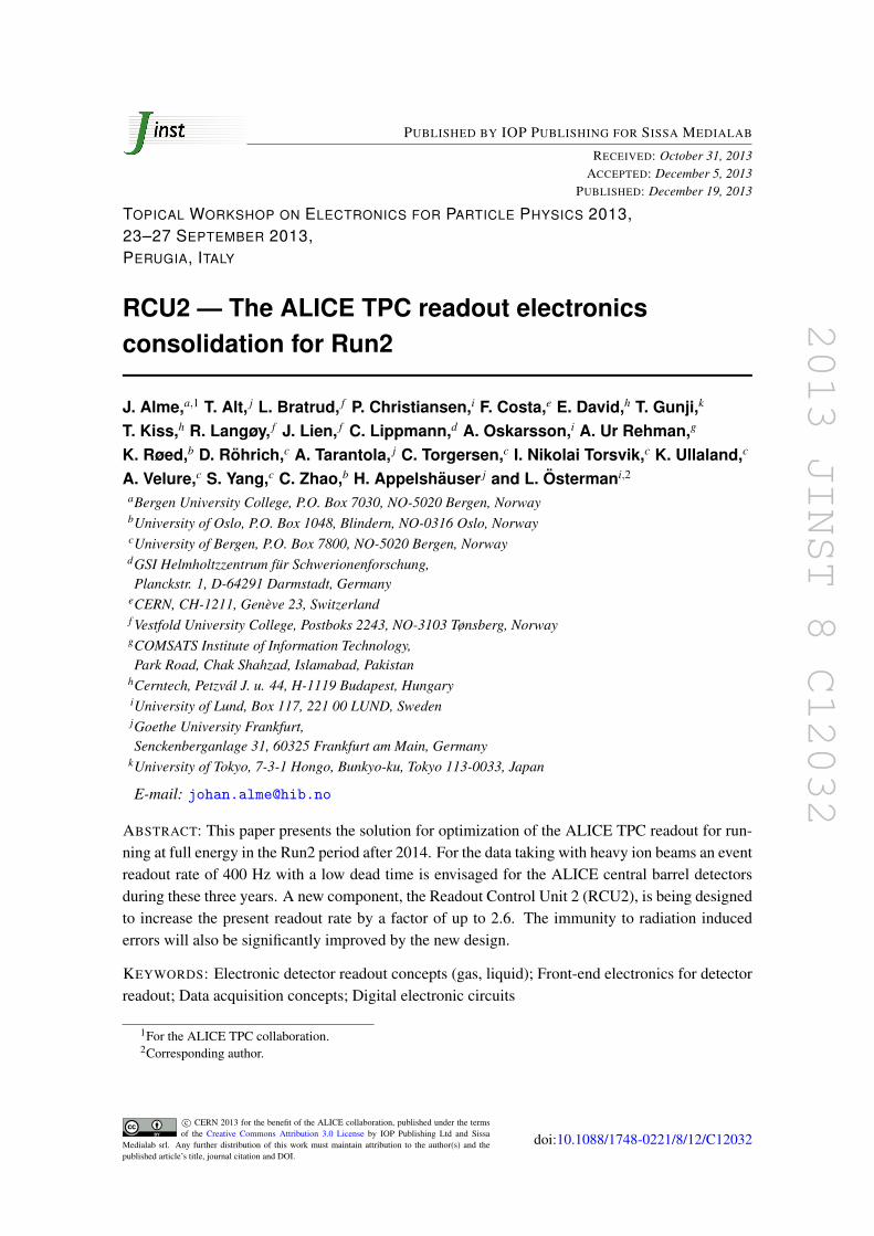
The main motivation for the RCU2 is to develop a solution that gives the needed performanceimprovement and at the same time is feasible within the limited time-frame of LS1 The RCU2was initiated only in April 2013 giving less than 20 months to complete the project includingdesign prototyping mass-production and commissioning This demanding time-schedule impliesthat there is no room for rearranging the infrastructure or architecture of the present TPC readoutelectronics The cables for Ethernet Trigger DAQ and power must all be reused as is Even ifidentified as the bottleneck of the present system the GTL bus must also remain However eachGTL bus is split into into four branches per RCU2 instead of two see figure 2 This ensures at leasta doubling of the data rate which requires an upgraded DDL link as well Using the same fiberthis is updated to the DDL2 protocol [16] with a bandwidth of 3125 Gbps or 5 Gbps
ndash 4 ndash
2013 JINST 8 C12032
As shown in figure 2 the RCU2 hosts a Microsemi SmartFusion2 (SF2) System-on-Chip(SoC) FPGA M2S050-1FG896 [17 18] This is a state of the art flash-based FPGA that hasSEU immune configuration memory as well as several other radiation tolerance measures im-plemented [18] (see section 7) Since most of the the stability issues seen in Run1 can be tracedback to SEUs in the configuration memory of the FPGA these issues will be avoided just by thechange of technology It also comes with a Microcontroller Subsystem [19] which is based on ahardcore ARM Cortex-M3 microcontroller and many peripheral cores
41 GTL backplane design
The shape of the TPC sector implies that different backplane designs are needed for the six readoutpartitions in one sector For the RCU2 the existing two backplane branches A and B are furthersplit forming four separate branches A inner A outer B inner and B outer This implies thateach backplane is electrically split giving two separate branches on the same PCB It has beendecided to keep the PCB formfactor of the original backplanes as the position and angle of eachFEC connector needs to be correct with sub millimeter precision Even though the branches varyboth in length and in the number of FECs connected it is important that the connectors towards theRCU2 are located at fixed positions
42 RCU2 hardware design
The formfactor and the placement of connectors and components on the RCU2 is largely decidedby the wish to reuse the copper cooling envelopes from the RCU1 [2] The water cooling providedby the cooling envelopes will be needed since the GTL driver chips dissipate a lot of heat Apower consumption of about 22 W divided between the 43 V and 35 V power supplies have beenestimated where the equivalent number for the RCU1 is less than 10 W
TTC interface The data on the TTC link is transmitted using a 160 MHz biphase differentialmanchester encoded signal [20] The data payload is split into channel A and B where channel Ais used for sending level 0 and level 1 trigger while channel B is used for trigger information (eglevel 2 triggers) On the RCU1 the clock and data recovery (CDR) and the channel splitting isdone by the radiation tolerant TTC receiver chip (TTCrx) [20] One important point of the TTCrxis that the clock is recovered with a predefined phase-offset to the LHC input clock since it is usedas the base of the sampling clock and the phase of the sampling clock must be aligned for all ofthe 216 RCUs
One of the main challenges during the design of the RCU2 is that the TTCrx is out of stock andno new production runs are foreseen Solutions for replacing the TTCrx have been suggested [21]but none of them are intended for use in a radiation environment Our solution is to use the AvagoHFBRndash2316TZ [22] of which an earlier version of the device was qualified by the TTC group atCERN [23] in 2003 A standard limiting amplifier follows the optical receiver to convert the signalto a digital LVDS signal which is connected directly to user IOs on the FPGA where the CDR andchannel splitting is implemented Since no data exist on the limiting amplifier regarding radiationtolerance and the data on the optical receiver is from a previous version the components in theTTC chain will be tested for radiation tolerance early 2014 as part of the full system test mentionedin section 7
ndash 5 ndash
2013 JINST 8 C12032
DCS interface The DCS interface is designed using a Marvell 88E1111 Ethernet PHY [24]connected to the Serial Deserialiser (SERDES) of the SF2 The advantages of this PHY are thatthere are no magnetic components inside that it uses few IOs on the SF2 and that it gives a linkspeed of 100 Mbps opposed to 10 Mbps as on the DCS board A design without transformersis needed because of the ALICE magnetic field The solution for the analog part is taken overfrom the present DCS board design [25] which has proven to be quite reliable There have beenproblems with communication losses on the Ethernet link but these are not related to the analogdesign Tests have been performed that shows that the Marvell PHY without transformer satisfiesthe requirements Irradition tests of the Marvell PHY will be performed early 2014 as part of thefull system test mentioned in section 7 However it is not regarded as a high risk component sincea loss of communication is not critical to the data taking and it is possible to reset the PHY fromthe SF2 if communication losses are detected
DAQ interface The DAQ interface is designed using an small formfactor pluggable (SFP) opti-cal transceiver that is connected to the onchip SERDES on the SF2 The DDL2 protocol module isdelivered by the ALICE DAQ group as a SF2 compatible IP core with the same front-end interfaceas on the RCU1 This makes the integration of the module easy
43 Radiation monitor
The RCU1 includes a reconfiguration network comprised of a flash-based FPGA and a flash mem-ory device which is used for active partial reconfiguration of the main FPGA design [26] Addi-tionally this is a powerful radiation monitor that has given valuable results concerning the impactof the radiation enviroment on the RCU1 [12 27]
The reconfiguration network is made obsolete on the RCU2 with the introduction of the SF2FPGA However the radiation monitoring functionality should be kept A Microsemi ProASIC3A3P250 [28] and four Cypress 8 Mbit SRAM memories [29] have been included on the board toimplement this The particular type of SRAMs are equal to those used on the latest LHC RadMondevices meaning that they are extensively characterised [30] The additional FPGA is needed sincethe SF2 lacks the pin resources for the SRAM interfaces It should be emphasized that the RadMondesign has been done as a standalone project earlier [31] so the extra functionality comes with avery low risk
5 RCU2 FPGA design
The strict time constraint of the upgrade project implies that the design is largely based on thepresent RCU1 FPGA design An important point is that the RCU1 FPGA design has proven towork very well if the radiation related functional failures are disregarded
The proposed design is given in figure 3 The overall structure of the design is inheritedfrom the RCU1 The inclusion of the embedded ARM Cortex M3 core on the FPGA is a majorsimplification regarding the DCS bus interface compared to the present design Additionally therich selection of hardcore peripherals provided by the Microcontroller Subsystem is utilized whereappropriate for instance the I2C interface to the ADCs and EEPROM the SPI to the RadMon andexternal flash device and the DDR interface to the external memory
ndash 6 ndash
2013 JINST 8 C12032
ClockData
Recovery Module
TTCClk 40Mhz
TTC Ch A
TTC Ch B
Trigger InterfaceModule
Altro Interfac
e Module
FCBus
If
Altro Interfac
e Module
FCBus If
Altro Interfac
e Module
FCBus If
FEC Interface Module
Branch B_outer
DDL2 Interface (SERDES)
APB bus decoder
Arbiter
Result Unit
Instruction Sequencer
Data Assembler
Event Manager
CDH
DD
L2 d
ata
Raw data
ARM Cortex M3 CPU(Linux)
SoC
PLD
PLD programminginterface
Hardcore interfacesSPI FLASH DDR23 Mem
RadMONMicrosemi Flashpro
FPGA
TTC
DAQ
DCS
4 branches ndash 18-25 FECs
Smartfusion2
Triggers
CDH
TTC
Ch
ATT
C C
h B
RCU Bus
ChunkFIFO
4 x databusFC
Bus If BO
SPIcore
ADCsTemperature
voltage current monitoring
I2Ccore
GTL busFrontend Control Bus
HardwareID EEPROM
JTAG programming IF
Ethernet
FICIF core
FICIF core
System Controller
AP
B
CLK 160 MHz
JTAG IF
CLKManager
Ported from RCU1
New Module
Partly New Module
AP
B
TTC
Clk
40
Mh
z
16
0 M
Hz
80 MHz
Sysc
lk4
0M
hz
Figure 3 Simplified block schematic of the proposed RCU2 FPGA design
Control system Apart from some of the hardcore IP cores in the SF2 that are used for monitoringpurposes the Frontend Control Bus Interface is the only dedicated control system component inthe SF2 This module implements the custom I2C interface to the FECs used for monitoring ofcurrents voltages and temperatures on the FECs [32] To improve the partitioning of the designthis module is connected to a separate fabric interface core (FIC) of the Microcontroller Subsystemthan the rest of the logic in the RCU2 FPGA
Readout scheme A new readout scheme has been developed in order to utilize the improvedparallelism of the RCU2 and so that the data analysis on the receiver side can be done as efficientlyas possible The receiver side expects the data to be ordered pad by pad and padrow by padrowAs seen in figure 3 there is one readout module per branch The data from the channels (pads) forone single padrow belonging to one single branch is called a chunk of data and the readout modulestores this data into one large chunk FIFO The channels in the padrows are divided between thebranches so that one can read out the chunk FIFOs consecutively in a round robin fashion andautomatically keep the data in the correct order
Except for the new structure with chunk FIFOs most of the readout module is kept as ex-plained in [11] However the increase in bandwidth given by the DDL2 implies that the readoutof the data is separated in different clock domains The data is read from the FECs with a 40 MHzclock (constrained by the FEC) into a buffer memory then stored into the chunk FIFO at 80 MHz
ndash 7 ndash
2013 JINST 8 C12032
and finally read by the Data Assembler from the chunk FIFOs at 160 MHz This ensures that nobandwidth limitations are imposed by the readout logic The different clocks are generated fromthe recovered TTC clock using an onchip Phase Locked Loop (PLL)
Other new functionality To further improve the efficiency of the data readout the RCU2 FPGAwill implement a new feature which discards junk data on the fly Junk data typically comes frominstabilities in the High Voltage system of the TPC and is recognized by several channels that havefar more data than expected This can be detected already at the RCU2 level by setting thresholdlevels regarding expected data size and the RCU2 will simply not send these data to DAQ systemat all Simulations have shown that no good physics data is discarded by this algorithm
Readout performance simulations A simulation of the readout architecture has been devel-oped in SystemC [33] The focus of these simulations is the verification of the performance gaindue to the new readout scheme and the confirmation that the resources offered by the SF2 de-vice in particular the available fabric memory blocks to be used for the chunk FIFOs are suf-ficient The simulation is based on real data from heavy ion collisions at different centralities(varying data sizes) recorded with the TPC in 2010 Different readout modes and hardware param-eters (eg FIFO depth) are simulated The readout time contains also the trigger delays and otherexternal parameters
Compared to the measurements of the present system where the readout time for central eventsis about 4 ms [11] the first simulation results using data from 170 events indicates a readout timeof approximately 15 ms that is an improvement factor of about 26 for the RCU2
6 RCU2 DCS software
The inclusion of an Embedded Linux platform [34] on the RCU2 is permitting to reuse most of theexisting low level DCS software more specifically the FeeServer and the intercom layer [35] Theexception is the drivers for the RCU2 DCS which must be redesigned since the hardware interfaceof the RCU2 is different compared to the DCS board
It was considered to discard the DCS implementation and instead send monitoring data inparallel to the physics data stream through the optical readout link The latter might be reconsideredin the future However having a secondary interface that is capable of configuration and monitoringincreases the flexibility of the RCU2 by giving redundant access to the complete RCU2 addressspace Regardless of not playing any role in the event readout itself the DCS can still be used toconfigure the FEE to perform readout In addition upgrading the designs in the RadMon FPGAand the SF2 fabric is much easier when the Linux is installed on the Microcontroller Subsystem
7 Radiation tolerance measures and irradiation campaigns
Due to the increased luminosity the radiation load to the electronic components will also increasewith respect to Run1 Radiation calculations for the present ALICE detector have previously beenpresented in [36] where the expected high energy hadron fluence rate (gt20MeV) was estimatedto 08 kHzcm2 for the worst case location of the TPC electronics and for an interaction rate of8 kHz Scaling this fluence rate to an interaction rate of 30 kHz the expected value for Run2
ndash 8 ndash
2013 JINST 8 C12032
becomes 3 kHzcm2 which is a significant rate The choice of the flash based Microsemi SF2FPGA is therefore essential as the configuration memory of these devices are stated to be immuneto SEUs [18] This device also offers SEU protected memories DDR bridges Ethernet cores etcand the DDR23 controllers are optionally secured with SECDED [18] The latter is expected toimprove the DCS stability since the Linux is uploaded to this memory on bootup For the usermemory and registers some mitigation means are needed and will be implemented
For the total dose and 1 MeV neutron-equivalent fluence the initial numbers from [36] were16 kRad and 45x1010 cmminus2 respectively and this for a total operation of 10 ALICE years As-suming a similar running program of pp p-Pb and Pb-Pb interactions and then scaling for a 3 yearrunning period of Run2 including an increased interaction rate of 30 kHz for Pb-Pb the expectednumbers for the total dose and 1 MeV neutron-equivalent fluence will be roughly similar to thosereported in [36] A dose of less than a few kRads and similar a 1 MeV neutron-equivalent fluencein the order of 1010 cmminus2 are not very significant as the onset for failure typically occurs for dosevalue above 10 kRad and 1 MeV neutron-equivalent fluence values of 1011 cmminus2 [37] It shouldalso be noted that the radiation calculations in [36] already contains a safety factor (2 to 3) becausethe multiplicity was overestimated for these calculations
On a PCB level there has been emphasis on the use of components already proven to functionwell in a radiation environment For components selected where no data regarding radiation toler-ance can be found an irradiation campaign at the Oslo Cyclotron is presently being prepared In thebeginning of 2014 an irradiation campaign of the full readout chain will be done either at The Sved-berg Laboratory (TSL) in Uppsala or at the Paul Scherrer Institute (PSI) in Zurich At both theselocations higher beam energies are available (for instance 180 MeV protons and neutrons at TSL)
8 Outlook and conclusions
The aim of the RCU2 is to do a smallndashscale upgrade project that enables ALICE to collect asignificantly larger amount of events in the central barrel at a moderate cost The cost is estimatedto be about 455 kCHF The readout time for TPC events is simulated to be improved by a factor of26 for central heavy ion events which enables the TPC readout to conform to the running scenariothat is envisaged for Run2 of ALICE The stability problems seen in Run1 will most likely bereduced to a negligible level but this is yet to be confirmed by the irradiation campaigns
The RCU2 is a project that relies quite heavily on the reuse of the current design and ideasThis reduces the risk of the project substantially The biggest risk has been identified to be theaggressive timendashschedule The first prototype of the RCU2 is expected to be produced by the endof the year and the mass production will be done from April 2014 The installation on the detectoris planned in October 2014 after which the commissioning period starts This will last until March2015 At the time of writing the progress of the project is approximately as originally planned
References
[1] ALICE collaboration ALICE Experiment at the CERN LHC 2008 JINST 3 S08002
[2] J Alme et al The ALICE TPC a large 3-dimensional tracking device with fast readout for ultra-highmultiplicity events Nucl Instrum Meth A 622 (2010) 316
ndash 9 ndash
2013 JINST 8 C12032
[3] K Safarik Overview of recent ALICE results Nucl Phys A 904 (2013) 27C
[4] Altera Excalibur devices hardware reference manual v31 (Nov 2002)
[5] D Evans et al The ALICE Central Trigger System Real Time Conference 2005 14th IEEE-NPSS(2005) 5
[6] J Alme et al Radiation-tolerant SRAM-FPGA based trigger and readout electronics for the ALICEexperiment IEEE Trans Nucl Sci 55 (2008) 76
[7] Xilinx Inc Virtex-II Pro and Virtex-II Pro X platform FPGAs complete data sheet DS083 v47(Nov 2007)
[8] Actel Corporation Actel ProASICplus flash family FPGAs datasheet v57 (Sept 2008)
[9] F Lima Karstensmidt et al Fault-tolerance techniques for SRAM-based FPGAs Springer Germany(2006)
[10] J Alme Firmware development and integration for ALICE TPC and PHOS front-end electroncisPhD thesis University of Bergen Bergen Norway (2008)
[11] A Ur Rehman The ALICE TPC readout electronics mdash Design performance optimization andverification of the DAQ circuit PhD thesis University of Bergen Bergen Norway (2012)
[12] J Alme et al Radiation tolerance studies using fault injection on the readout control FPGA designof the ALICE TPC detector 2013 JINST 8 C01053
[13] K Roslashed and J Alme Single event upsets in the readout control FPGA of the ALICE TPC detectorduring the first LHC running period poster session at Topical Workshop on Electronics for ParticlePhysics 2013 September 23ndash27 Perugia Italy (2013)
[14] A Junique et al Upgrade of the ALICE-TPC read-out electronics 2010 JINST 5 C21026
[15] V Holsen Upgrade of the readout electronics for the ALICE TPC Master thesis University ofBergen Bergen Norway (2013)
[16] F Costa DAQ readout after LS1 and LS2 at ALICE week presentation (2012)
[17] Microsemi Inc SmartFusion2 system-on-chip FPGAs datasheet rev 4 (Jun 2013)
[18] Microsemi Inc SmartFusion2 system-on-chip FPGAs product brief rev 12 (Oct 2013)
[19] Microsemi Inc SmartFusion2 microcontroller subsystem user guide rev 4 (Sept 2013)
[20] J Christiansen et al TTCrx reference manual mdash A timing trigger and control receiver ASIC for LHCdetectors v 311 (Dec 2005)
[21] M Dimitriyev et al Development of a microTCA carrier hub for CMS at HL-LHC 2010 JINST 5C12042
[22] Avago HFBR-1312TZ transmitter HFBR-2316TZ receiver 1300 nm fiber optic transmitter andreceiver datasheet av02-1500en edition (2012)
[23] M Gastal and P Moreira Radiation qualification of commercial off-the-shelf P-I-N receivers for theTTC system Technical Report CERN-EPMIC Geneva Switzerland (2003)
[24] Marvell Marvell 88E1111 product brief integrated 101001000 Ultra Gigabit Ethernet Transceivermv-s105540 rev a (Oct 2013)
[25] DCS Board Schematic board v 164 (Dec 2005)
[26] J Alme et al Case study of a solution for active partial reconfiguration of a Xilinx Virtex-II Pro inthe proceedings of 3rd FPGAWorld conference Stockholm Sweden (2006)
ndash 10 ndash
2013 JINST 8 C12032
[27] K Roslashed et al First measurement of single event upsets in the readout control fpga of the ALICE TPCdetector 2011 JINST 6 C12022
[28] Microsemi ProASIC3 flash family FPGAs with optional soft ARM support datasheet rev 13 (Jan2013)
[29] Cypress Perform CY62157EV30 MoBL 8 Mbit (512K x 16) Static RAM datasheet rev f (Jun 2009)
[30] A Masi et al The new generation of the CERN accelerator radiation monitoring system forelectronics IEEE Trans Nucl Sci 60 (2013) 3475
[31] A Velure Design implementation and testing of SRAM based neutron detectors Master thesisUniversity of Bergen Bergen Norway (2011)
[32] C G Gutierrez Readout and control system for the ALICE TPC electronics PhD thesis EscuelaTecnica Suprior de Ingenieros Industrriales y de Telecomunicacion University of Cantabria Spain(2007)
[33] Accellera Systems Initiative SystemC webpage httpwwwsystemCorg
[34] EmCraft Systems Linux Cortex-M userrsquos manual rel 1110 (Jul 2013)
[35] DT Larsen Monitoring and calibration of the ALICE Time Projection Chamber PhD thesisUniversity of Bergen Bergen Norway (2010)
[36] A Morsch and B Pastircak Radiation in ALICE detectors and electronic racksALICE-INT-2002-28 (2004)
[37] CC Foster Total ionizing dose and displacement-damage effects in microelectronics MRS Bulletin28 (2003) 136
ndash 11 ndash
- Introduction
- Present TPC readout electronics
-
- Motivation for the RCU2 upgrade
-
- Alternative LS1 upgrade proposals
- RCU2
-
- GTL backplane design
- RCU2 hardware design
- Radiation monitor
-
- RCU2 FPGA design
- RCU2 DCS software
- Radiation tolerance measures and irradiation campaigns
- Outlook and conclusions
-
2013 JINST 8 C12032
PUBLISHED BY IOP PUBLISHING FOR SISSA MEDIALAB
RECEIVED October 31 2013ACCEPTED December 5 2013
PUBLISHED December 19 2013
TOPICAL WORKSHOP ON ELECTRONICS FOR PARTICLE PHYSICS 201323ndash27 SEPTEMBER 2013PERUGIA ITALY
RCU2 mdash The ALICE TPC readout electronicsconsolidation for Run2
J Almea1 T Alt j L Bratrud f P Christianseni F Costae E Davidh T Gunjik
T Kissh R Langoslashy f J Lien f C Lippmannd A Oskarssoni A Ur Rehmang
K Roslashedb D Rohrichc A Tarantola j C Torgersenc I Nikolai Torsvikc K Ullalandc
A Velurec S Yangc C Zhaob H Appelshauser j and L Ostermani2
aBergen University College PO Box 7030 NO-5020 Bergen NorwaybUniversity of Oslo PO Box 1048 Blindern NO-0316 Oslo NorwaycUniversity of Bergen PO Box 7800 NO-5020 Bergen NorwaydGSI Helmholtzzentrum fur SchwerionenforschungPlanckstr 1 D-64291 Darmstadt Germany
eCERN CH-1211 Geneve 23 Switzerlandf Vestfold University College Postboks 2243 NO-3103 Toslashnsberg NorwaygCOMSATS Institute of Information TechnologyPark Road Chak Shahzad Islamabad Pakistan
hCerntech Petzval J u 44 H-1119 Budapest HungaryiUniversity of Lund Box 117 221 00 LUND SwedenjGoethe University FrankfurtSenckenberganlage 31 60325 Frankfurt am Main Germany
kUniversity of Tokyo 7-3-1 Hongo Bunkyo-ku Tokyo 113-0033 Japan
E-mail johanalmehibno
ABSTRACT This paper presents the solution for optimization of the ALICE TPC readout for run-ning at full energy in the Run2 period after 2014 For the data taking with heavy ion beams an eventreadout rate of 400 Hz with a low dead time is envisaged for the ALICE central barrel detectorsduring these three years A new component the Readout Control Unit 2 (RCU2) is being designedto increase the present readout rate by a factor of up to 26 The immunity to radiation inducederrors will also be significantly improved by the new design
KEYWORDS Electronic detector readout concepts (gas liquid) Front-end electronics for detectorreadout Data acquisition concepts Digital electronic circuits
1For the ALICE TPC collaboration2Corresponding author
ccopy CERN 2013 for the benefit of the ALICE collaboration published under the termsof the Creative Commons Attribution 30 License by IOP Publishing Ltd and Sissa
Medialab srl Any further distribution of this work must maintain attribution to the author(s) and thepublished articlersquos title journal citation and DOI
doi1010881748-0221812C12032
2013 JINST 8 C12032
Contents
1 Introduction 1
2 Present TPC readout electronics 221 Motivation for the RCU2 upgrade 3
3 Alternative LS1 upgrade proposals 4
4 RCU2 441 GTL backplane design 542 RCU2 hardware design 543 Radiation monitor 6
5 RCU2 FPGA design 6
6 RCU2 DCS software 8
7 Radiation tolerance measures and irradiation campaigns 8
8 Outlook and conclusions 9
1 Introduction
The Large Hadron Collider (LHC) accelerates protons and lead ions close to the speed of light andcollides them inside the four experimental areas along the beamline One of the LHC experimentsis A Large Ion Collider Experiment (ALICE) [1]
The ALICE detector comprises several sub-detectors of which one is the Time ProjectionChamber (TPC) [2] The TPC detector is the main tracking detector of ALICE The end plates onboth sides of the TPC barrel are populated with 557 568 readout pads The TPC readout electronicsis located directly behind the two detector end plates
Following a successful running period from November 2009 to January 2013 (Run1) [3] theLHC is currently shut down for maintenance and preparation for even higher energies and lumi-nosities This period named Long Shutdown 1 (LS1) lasts end of 2014
The next running period (Run2) is between 2015 and 2018 In this period a peak luminosity upto 4x1027 cm-2s-1 can be expected for Pb-Pb collisions with centre-of-mass energy of 55 TeV pernucleon pair As a comparison in the heavy ion run in 2011 the luminosity reached 1026 cm-2s-1 [3]The envisaged luminosities for Run2 correspond to interaction rates from 8 to 30 kHz To get max-imum benefit from the delivered luminosities the most attractive data taking scenario for ALICEforesees data taking rates of at least a factor two faster than what can be achieved with the cur-rent TPC readout electronics For a trigger mix containing central semi-central minimum bias
ndash 1 ndash
2013 JINST 8 C12032
RCU1
TTC (optic link)
MonitorControl (Ethernet)
DDL link (optic ndash 1280 Gbs)
Xilinx Virtex-2pro
Actel FPGA
FEC
s ndash
Bra
nch
AFE
Cs
ndash B
ran
ch B
GTL
bu
s br
anch
AG
TL b
us
bran
ch B
DCS board
AlteraFPGA
ActelFPGA
SIU card
Figure 1 Sketch of the present TPC readout electronics with the RCU1
calorimeter and Transition Radiation Detector (TRD) triggers an event readout rate of at least400 Hz is envisaged for the ALICE central barrel detectors while keeping a reasonably low deadfraction (busy time) In comparison the maximum achieved readout rate for the same trigger mixof the current TPC readout electronics has been measured to be about 320 Hz (in this case with highdead fraction) The higher luminosities for Run2 will also lead to a 40 increase in the event sizessince the number of tracks per interaction will be higher The maximum event size for a centralevent in Run1 is 65 MB for Run2 a corresponding event will produce 90 MB of data
This paper presents the RCU2 which is the replacement of the present Readout Control UnitIt is currently being developed in order to provide a readout system capable to achieve the discussedperformance requirements
2 Present TPC readout electronics
A sketch of the present TPC readout electronics [2] is shown in figure 1 and consist of a ReadoutControl Unit (RCU) that connects to between 18 and 25 Front End Cards (FECs) depending onthe radial position of the RCU in the TPC barrel The radial direction is divided into 6 readoutpartitions with one RCU each The connectivity between the RCU and the FECs is implementedusing two branches of a multidrop parallel Gunning Transistor Logic (GTL) bus with a bandwidth16 Gbps The FEC itself has 128 analog input channels with each input channel corresponding toa single detector pad on the TPC detector
The present RCU from here on referred to as RCU1 consists of a motherboard with two at-tached mezzanine cards the Source Interface Unit (SIU) and the Detector Control System (DCS)board The SIU hosts one flash based FPGA and is the interface card implementing the Detec-tor Data Link (DDL) The DDL is a custom protocol on a 1280 Gbps bidirectional optical linkconnecting the RCU1 to the Data Acquisition (DAQ) system [2] The TPC uses this interface fortransmitting the event data for further online and offline analysis and for configuration of the FrontEnd Electronics (FEE)
The DCS board host an SRAM based FPGA with an embedded ARM processor core [4] Itis configured with a small Embedded Linux platform and communicates to the higher layer of the
ndash 2 ndash
2013 JINST 8 C12032
DCS system [2] via a special transformerless Ethernet connection In addition it has an opticalinterface receiving the clock and trigger information from the Timing Trigger and Control [5 6]
The RCU1 motherboard hosts two FPGAs The main FPGA where the data readout function-ality is implemented is an SRAM based Xilinx Virtex2pro-vp7 [7] while the support FPGA is aFlash based Actel APA075 [8] The purpose of the support FPGA is to program the main FPGAfrom an onboard Flash memory It also implements Active Partial Reconfiguration to detect andcorrect Single Event Upsets (SEUs) [9] in the configuration memory of the main FPGA [10]
21 Motivation for the RCU2 upgrade
The present TPC readout electronics will be a limiting factor with the foreseen readout rate forRun2 In addition to this stability issues have been observed during Run1 some of which can betraced to the SEUs in the SRAM based FPGAs By itself this is not necessarily a problem becauseof the implementation of Active Partial Reconfiguration However the FPGA resources are fullyutilized and there is no room for design level mitigation This implies that a single event upset(SEU) in a sensitive SRAM cell automatically leads to a functional failure
Data rate limitations The GTL bus between the RCU1 and the FECs is implemented as a 40 bitwide parallel bus where the RCU1 connects to two separate branches Each of the two buses has abandwidth of 16 Gbps and reads the data from up to 13 FECs depending on the readout partitionand branch For high occupancy events like central Pb-Pb collisions the data readout through theGTL buses is the bottleneck of the readout system The readout time is determined by the slowestreadout partition which is the second one from inside Readout Partition 1 (RP1) The occupancyis highest on the inner partitions and RP1 has the largest number of FECs connected (25) Since theGTL bus is separated into two branches here up to 13x128 channels must be read out sequentiallyThe readout time is characterized by an overhead needed for addressing of the channels and the16 Gbps datarate of the GTL bus It has been measured for pp and Pb-Pb collisions in 2010 [11]For central Pb-Pb events the readout time reaches up to 4 ms depending on the number of tracksper event
Stability issues The current readout system is not radiation tolerant and suffers from radiationeffects In the 2013 p-Pb data taking at high interaction rates (up to 200 kHz) 9 of all data takingsessions (runs) had to be stopped (or were stopped automatically) due to errors that occurred inthe TPC readout electronics These errors which lead to the readout getting stuck (busy) or tocorrupted event headers can be assigned to radiation effects where SEUs in the configurationmemory of the FPGA is the dominant factor The SEU sensitivity of the current RCU1 FPGAdesign has been characterized [12] and it was found that approximately 1 of the SEUs leads toa premature abort of a run Based on the potential luminosity for Run2 and on the analysis of theSEU rate for the heavy ion runs in 2011 it can be expected that the ALICE data taking will stopevery hour if no measures are taken [13]
Also the DCS boards suffer from radiation related communication errors (DCS to RCU) andcommunication losses (Ethernet to DCS system) Even though uncritical for the data taking theloss of monitoring capabilities has to be avoided
ndash 3 ndash
2013 JINST 8 C12032
RCU2
TTC (optic link)
MonitorControl (Ethernet)
DDL2 link (optic ndash 5 Gbs)
FEC
sB
ran
ch B
O
A_o
ute
rA
_in
ner
B_i
nn
erB
_ou
ter
FEC
sB
ran
ch B
IFE
Cs
Bra
nch
AO
FEC
sB
ran
ch A
I Electrical Split
Electrical Split
Micro-semiSF2
RadMon
SRAMSRAMSRAMSRAM
Figure 2 Sketch of RCU2 highlighting the main differences from RCU1
Conclusion The present TPC readout electronics will not be able to fulfill the ALICE ambitionsfor Run2 with the foreseen 40 increase in event size and the envisaged readout rate of 400 HzThe stability problems are also expected to become worse with the present solution under the Run2conditions (see section 7) With this in mind it is clear that an upgrade is needed
3 Alternative LS1 upgrade proposals
Two upgrade options for LS1 have been discussed for the TPC electronics The first option was tomake a small add-on board the Front End Card Interface (FECint) board to be connected to theFEC with the purpose of translating the wide parallel bus into a high speed serial link The initialidea of this design is given in [14] A second prototype of the FECint board was designed in 2012where two FECs are connected in parallel to one FECint [15]
This upgrade solution has two main advantages (1) No bandwidth limitations are imposed bythe readout electronics and (2) it is relevant for the upgrades planned for Long Shutdown 2 (LS2)given the fact that it would use components and an infrastructure that would be reminiscent of theplanned LS2 upgrade However this upgrade-plan was not prioritized as it was too ambitious giventhe time-budget available Instead it was decided to develop the RCU2
4 RCU2
The main motivation for the RCU2 is to develop a solution that gives the needed performanceimprovement and at the same time is feasible within the limited time-frame of LS1 The RCU2was initiated only in April 2013 giving less than 20 months to complete the project includingdesign prototyping mass-production and commissioning This demanding time-schedule impliesthat there is no room for rearranging the infrastructure or architecture of the present TPC readoutelectronics The cables for Ethernet Trigger DAQ and power must all be reused as is Even ifidentified as the bottleneck of the present system the GTL bus must also remain However eachGTL bus is split into into four branches per RCU2 instead of two see figure 2 This ensures at leasta doubling of the data rate which requires an upgraded DDL link as well Using the same fiberthis is updated to the DDL2 protocol [16] with a bandwidth of 3125 Gbps or 5 Gbps
ndash 4 ndash
2013 JINST 8 C12032
As shown in figure 2 the RCU2 hosts a Microsemi SmartFusion2 (SF2) System-on-Chip(SoC) FPGA M2S050-1FG896 [17 18] This is a state of the art flash-based FPGA that hasSEU immune configuration memory as well as several other radiation tolerance measures im-plemented [18] (see section 7) Since most of the the stability issues seen in Run1 can be tracedback to SEUs in the configuration memory of the FPGA these issues will be avoided just by thechange of technology It also comes with a Microcontroller Subsystem [19] which is based on ahardcore ARM Cortex-M3 microcontroller and many peripheral cores
41 GTL backplane design
The shape of the TPC sector implies that different backplane designs are needed for the six readoutpartitions in one sector For the RCU2 the existing two backplane branches A and B are furthersplit forming four separate branches A inner A outer B inner and B outer This implies thateach backplane is electrically split giving two separate branches on the same PCB It has beendecided to keep the PCB formfactor of the original backplanes as the position and angle of eachFEC connector needs to be correct with sub millimeter precision Even though the branches varyboth in length and in the number of FECs connected it is important that the connectors towards theRCU2 are located at fixed positions
42 RCU2 hardware design
The formfactor and the placement of connectors and components on the RCU2 is largely decidedby the wish to reuse the copper cooling envelopes from the RCU1 [2] The water cooling providedby the cooling envelopes will be needed since the GTL driver chips dissipate a lot of heat Apower consumption of about 22 W divided between the 43 V and 35 V power supplies have beenestimated where the equivalent number for the RCU1 is less than 10 W
TTC interface The data on the TTC link is transmitted using a 160 MHz biphase differentialmanchester encoded signal [20] The data payload is split into channel A and B where channel Ais used for sending level 0 and level 1 trigger while channel B is used for trigger information (eglevel 2 triggers) On the RCU1 the clock and data recovery (CDR) and the channel splitting isdone by the radiation tolerant TTC receiver chip (TTCrx) [20] One important point of the TTCrxis that the clock is recovered with a predefined phase-offset to the LHC input clock since it is usedas the base of the sampling clock and the phase of the sampling clock must be aligned for all ofthe 216 RCUs
One of the main challenges during the design of the RCU2 is that the TTCrx is out of stock andno new production runs are foreseen Solutions for replacing the TTCrx have been suggested [21]but none of them are intended for use in a radiation environment Our solution is to use the AvagoHFBRndash2316TZ [22] of which an earlier version of the device was qualified by the TTC group atCERN [23] in 2003 A standard limiting amplifier follows the optical receiver to convert the signalto a digital LVDS signal which is connected directly to user IOs on the FPGA where the CDR andchannel splitting is implemented Since no data exist on the limiting amplifier regarding radiationtolerance and the data on the optical receiver is from a previous version the components in theTTC chain will be tested for radiation tolerance early 2014 as part of the full system test mentionedin section 7
ndash 5 ndash
2013 JINST 8 C12032
DCS interface The DCS interface is designed using a Marvell 88E1111 Ethernet PHY [24]connected to the Serial Deserialiser (SERDES) of the SF2 The advantages of this PHY are thatthere are no magnetic components inside that it uses few IOs on the SF2 and that it gives a linkspeed of 100 Mbps opposed to 10 Mbps as on the DCS board A design without transformersis needed because of the ALICE magnetic field The solution for the analog part is taken overfrom the present DCS board design [25] which has proven to be quite reliable There have beenproblems with communication losses on the Ethernet link but these are not related to the analogdesign Tests have been performed that shows that the Marvell PHY without transformer satisfiesthe requirements Irradition tests of the Marvell PHY will be performed early 2014 as part of thefull system test mentioned in section 7 However it is not regarded as a high risk component sincea loss of communication is not critical to the data taking and it is possible to reset the PHY fromthe SF2 if communication losses are detected
DAQ interface The DAQ interface is designed using an small formfactor pluggable (SFP) opti-cal transceiver that is connected to the onchip SERDES on the SF2 The DDL2 protocol module isdelivered by the ALICE DAQ group as a SF2 compatible IP core with the same front-end interfaceas on the RCU1 This makes the integration of the module easy
43 Radiation monitor
The RCU1 includes a reconfiguration network comprised of a flash-based FPGA and a flash mem-ory device which is used for active partial reconfiguration of the main FPGA design [26] Addi-tionally this is a powerful radiation monitor that has given valuable results concerning the impactof the radiation enviroment on the RCU1 [12 27]
The reconfiguration network is made obsolete on the RCU2 with the introduction of the SF2FPGA However the radiation monitoring functionality should be kept A Microsemi ProASIC3A3P250 [28] and four Cypress 8 Mbit SRAM memories [29] have been included on the board toimplement this The particular type of SRAMs are equal to those used on the latest LHC RadMondevices meaning that they are extensively characterised [30] The additional FPGA is needed sincethe SF2 lacks the pin resources for the SRAM interfaces It should be emphasized that the RadMondesign has been done as a standalone project earlier [31] so the extra functionality comes with avery low risk
5 RCU2 FPGA design
The strict time constraint of the upgrade project implies that the design is largely based on thepresent RCU1 FPGA design An important point is that the RCU1 FPGA design has proven towork very well if the radiation related functional failures are disregarded
The proposed design is given in figure 3 The overall structure of the design is inheritedfrom the RCU1 The inclusion of the embedded ARM Cortex M3 core on the FPGA is a majorsimplification regarding the DCS bus interface compared to the present design Additionally therich selection of hardcore peripherals provided by the Microcontroller Subsystem is utilized whereappropriate for instance the I2C interface to the ADCs and EEPROM the SPI to the RadMon andexternal flash device and the DDR interface to the external memory
ndash 6 ndash
2013 JINST 8 C12032
ClockData
Recovery Module
TTCClk 40Mhz
TTC Ch A
TTC Ch B
Trigger InterfaceModule
Altro Interfac
e Module
FCBus
If
Altro Interfac
e Module
FCBus If
Altro Interfac
e Module
FCBus If
FEC Interface Module
Branch B_outer
DDL2 Interface (SERDES)
APB bus decoder
Arbiter
Result Unit
Instruction Sequencer
Data Assembler
Event Manager
CDH
DD
L2 d
ata
Raw data
ARM Cortex M3 CPU(Linux)
SoC
PLD
PLD programminginterface
Hardcore interfacesSPI FLASH DDR23 Mem
RadMONMicrosemi Flashpro
FPGA
TTC
DAQ
DCS
4 branches ndash 18-25 FECs
Smartfusion2
Triggers
CDH
TTC
Ch
ATT
C C
h B
RCU Bus
ChunkFIFO
4 x databusFC
Bus If BO
SPIcore
ADCsTemperature
voltage current monitoring
I2Ccore
GTL busFrontend Control Bus
HardwareID EEPROM
JTAG programming IF
Ethernet
FICIF core
FICIF core
System Controller
AP
B
CLK 160 MHz
JTAG IF
CLKManager
Ported from RCU1
New Module
Partly New Module
AP
B
TTC
Clk
40
Mh
z
16
0 M
Hz
80 MHz
Sysc
lk4
0M
hz
Figure 3 Simplified block schematic of the proposed RCU2 FPGA design
Control system Apart from some of the hardcore IP cores in the SF2 that are used for monitoringpurposes the Frontend Control Bus Interface is the only dedicated control system component inthe SF2 This module implements the custom I2C interface to the FECs used for monitoring ofcurrents voltages and temperatures on the FECs [32] To improve the partitioning of the designthis module is connected to a separate fabric interface core (FIC) of the Microcontroller Subsystemthan the rest of the logic in the RCU2 FPGA
Readout scheme A new readout scheme has been developed in order to utilize the improvedparallelism of the RCU2 and so that the data analysis on the receiver side can be done as efficientlyas possible The receiver side expects the data to be ordered pad by pad and padrow by padrowAs seen in figure 3 there is one readout module per branch The data from the channels (pads) forone single padrow belonging to one single branch is called a chunk of data and the readout modulestores this data into one large chunk FIFO The channels in the padrows are divided between thebranches so that one can read out the chunk FIFOs consecutively in a round robin fashion andautomatically keep the data in the correct order
Except for the new structure with chunk FIFOs most of the readout module is kept as ex-plained in [11] However the increase in bandwidth given by the DDL2 implies that the readoutof the data is separated in different clock domains The data is read from the FECs with a 40 MHzclock (constrained by the FEC) into a buffer memory then stored into the chunk FIFO at 80 MHz
ndash 7 ndash
2013 JINST 8 C12032
and finally read by the Data Assembler from the chunk FIFOs at 160 MHz This ensures that nobandwidth limitations are imposed by the readout logic The different clocks are generated fromthe recovered TTC clock using an onchip Phase Locked Loop (PLL)
Other new functionality To further improve the efficiency of the data readout the RCU2 FPGAwill implement a new feature which discards junk data on the fly Junk data typically comes frominstabilities in the High Voltage system of the TPC and is recognized by several channels that havefar more data than expected This can be detected already at the RCU2 level by setting thresholdlevels regarding expected data size and the RCU2 will simply not send these data to DAQ systemat all Simulations have shown that no good physics data is discarded by this algorithm
Readout performance simulations A simulation of the readout architecture has been devel-oped in SystemC [33] The focus of these simulations is the verification of the performance gaindue to the new readout scheme and the confirmation that the resources offered by the SF2 de-vice in particular the available fabric memory blocks to be used for the chunk FIFOs are suf-ficient The simulation is based on real data from heavy ion collisions at different centralities(varying data sizes) recorded with the TPC in 2010 Different readout modes and hardware param-eters (eg FIFO depth) are simulated The readout time contains also the trigger delays and otherexternal parameters
Compared to the measurements of the present system where the readout time for central eventsis about 4 ms [11] the first simulation results using data from 170 events indicates a readout timeof approximately 15 ms that is an improvement factor of about 26 for the RCU2
6 RCU2 DCS software
The inclusion of an Embedded Linux platform [34] on the RCU2 is permitting to reuse most of theexisting low level DCS software more specifically the FeeServer and the intercom layer [35] Theexception is the drivers for the RCU2 DCS which must be redesigned since the hardware interfaceof the RCU2 is different compared to the DCS board
It was considered to discard the DCS implementation and instead send monitoring data inparallel to the physics data stream through the optical readout link The latter might be reconsideredin the future However having a secondary interface that is capable of configuration and monitoringincreases the flexibility of the RCU2 by giving redundant access to the complete RCU2 addressspace Regardless of not playing any role in the event readout itself the DCS can still be used toconfigure the FEE to perform readout In addition upgrading the designs in the RadMon FPGAand the SF2 fabric is much easier when the Linux is installed on the Microcontroller Subsystem
7 Radiation tolerance measures and irradiation campaigns
Due to the increased luminosity the radiation load to the electronic components will also increasewith respect to Run1 Radiation calculations for the present ALICE detector have previously beenpresented in [36] where the expected high energy hadron fluence rate (gt20MeV) was estimatedto 08 kHzcm2 for the worst case location of the TPC electronics and for an interaction rate of8 kHz Scaling this fluence rate to an interaction rate of 30 kHz the expected value for Run2
ndash 8 ndash
2013 JINST 8 C12032
becomes 3 kHzcm2 which is a significant rate The choice of the flash based Microsemi SF2FPGA is therefore essential as the configuration memory of these devices are stated to be immuneto SEUs [18] This device also offers SEU protected memories DDR bridges Ethernet cores etcand the DDR23 controllers are optionally secured with SECDED [18] The latter is expected toimprove the DCS stability since the Linux is uploaded to this memory on bootup For the usermemory and registers some mitigation means are needed and will be implemented
For the total dose and 1 MeV neutron-equivalent fluence the initial numbers from [36] were16 kRad and 45x1010 cmminus2 respectively and this for a total operation of 10 ALICE years As-suming a similar running program of pp p-Pb and Pb-Pb interactions and then scaling for a 3 yearrunning period of Run2 including an increased interaction rate of 30 kHz for Pb-Pb the expectednumbers for the total dose and 1 MeV neutron-equivalent fluence will be roughly similar to thosereported in [36] A dose of less than a few kRads and similar a 1 MeV neutron-equivalent fluencein the order of 1010 cmminus2 are not very significant as the onset for failure typically occurs for dosevalue above 10 kRad and 1 MeV neutron-equivalent fluence values of 1011 cmminus2 [37] It shouldalso be noted that the radiation calculations in [36] already contains a safety factor (2 to 3) becausethe multiplicity was overestimated for these calculations
On a PCB level there has been emphasis on the use of components already proven to functionwell in a radiation environment For components selected where no data regarding radiation toler-ance can be found an irradiation campaign at the Oslo Cyclotron is presently being prepared In thebeginning of 2014 an irradiation campaign of the full readout chain will be done either at The Sved-berg Laboratory (TSL) in Uppsala or at the Paul Scherrer Institute (PSI) in Zurich At both theselocations higher beam energies are available (for instance 180 MeV protons and neutrons at TSL)
8 Outlook and conclusions
The aim of the RCU2 is to do a smallndashscale upgrade project that enables ALICE to collect asignificantly larger amount of events in the central barrel at a moderate cost The cost is estimatedto be about 455 kCHF The readout time for TPC events is simulated to be improved by a factor of26 for central heavy ion events which enables the TPC readout to conform to the running scenariothat is envisaged for Run2 of ALICE The stability problems seen in Run1 will most likely bereduced to a negligible level but this is yet to be confirmed by the irradiation campaigns
The RCU2 is a project that relies quite heavily on the reuse of the current design and ideasThis reduces the risk of the project substantially The biggest risk has been identified to be theaggressive timendashschedule The first prototype of the RCU2 is expected to be produced by the endof the year and the mass production will be done from April 2014 The installation on the detectoris planned in October 2014 after which the commissioning period starts This will last until March2015 At the time of writing the progress of the project is approximately as originally planned
References
[1] ALICE collaboration ALICE Experiment at the CERN LHC 2008 JINST 3 S08002
[2] J Alme et al The ALICE TPC a large 3-dimensional tracking device with fast readout for ultra-highmultiplicity events Nucl Instrum Meth A 622 (2010) 316
ndash 9 ndash
2013 JINST 8 C12032
[3] K Safarik Overview of recent ALICE results Nucl Phys A 904 (2013) 27C
[4] Altera Excalibur devices hardware reference manual v31 (Nov 2002)
[5] D Evans et al The ALICE Central Trigger System Real Time Conference 2005 14th IEEE-NPSS(2005) 5
[6] J Alme et al Radiation-tolerant SRAM-FPGA based trigger and readout electronics for the ALICEexperiment IEEE Trans Nucl Sci 55 (2008) 76
[7] Xilinx Inc Virtex-II Pro and Virtex-II Pro X platform FPGAs complete data sheet DS083 v47(Nov 2007)
[8] Actel Corporation Actel ProASICplus flash family FPGAs datasheet v57 (Sept 2008)
[9] F Lima Karstensmidt et al Fault-tolerance techniques for SRAM-based FPGAs Springer Germany(2006)
[10] J Alme Firmware development and integration for ALICE TPC and PHOS front-end electroncisPhD thesis University of Bergen Bergen Norway (2008)
[11] A Ur Rehman The ALICE TPC readout electronics mdash Design performance optimization andverification of the DAQ circuit PhD thesis University of Bergen Bergen Norway (2012)
[12] J Alme et al Radiation tolerance studies using fault injection on the readout control FPGA designof the ALICE TPC detector 2013 JINST 8 C01053
[13] K Roslashed and J Alme Single event upsets in the readout control FPGA of the ALICE TPC detectorduring the first LHC running period poster session at Topical Workshop on Electronics for ParticlePhysics 2013 September 23ndash27 Perugia Italy (2013)
[14] A Junique et al Upgrade of the ALICE-TPC read-out electronics 2010 JINST 5 C21026
[15] V Holsen Upgrade of the readout electronics for the ALICE TPC Master thesis University ofBergen Bergen Norway (2013)
[16] F Costa DAQ readout after LS1 and LS2 at ALICE week presentation (2012)
[17] Microsemi Inc SmartFusion2 system-on-chip FPGAs datasheet rev 4 (Jun 2013)
[18] Microsemi Inc SmartFusion2 system-on-chip FPGAs product brief rev 12 (Oct 2013)
[19] Microsemi Inc SmartFusion2 microcontroller subsystem user guide rev 4 (Sept 2013)
[20] J Christiansen et al TTCrx reference manual mdash A timing trigger and control receiver ASIC for LHCdetectors v 311 (Dec 2005)
[21] M Dimitriyev et al Development of a microTCA carrier hub for CMS at HL-LHC 2010 JINST 5C12042
[22] Avago HFBR-1312TZ transmitter HFBR-2316TZ receiver 1300 nm fiber optic transmitter andreceiver datasheet av02-1500en edition (2012)
[23] M Gastal and P Moreira Radiation qualification of commercial off-the-shelf P-I-N receivers for theTTC system Technical Report CERN-EPMIC Geneva Switzerland (2003)
[24] Marvell Marvell 88E1111 product brief integrated 101001000 Ultra Gigabit Ethernet Transceivermv-s105540 rev a (Oct 2013)
[25] DCS Board Schematic board v 164 (Dec 2005)
[26] J Alme et al Case study of a solution for active partial reconfiguration of a Xilinx Virtex-II Pro inthe proceedings of 3rd FPGAWorld conference Stockholm Sweden (2006)
ndash 10 ndash
2013 JINST 8 C12032
[27] K Roslashed et al First measurement of single event upsets in the readout control fpga of the ALICE TPCdetector 2011 JINST 6 C12022
[28] Microsemi ProASIC3 flash family FPGAs with optional soft ARM support datasheet rev 13 (Jan2013)
[29] Cypress Perform CY62157EV30 MoBL 8 Mbit (512K x 16) Static RAM datasheet rev f (Jun 2009)
[30] A Masi et al The new generation of the CERN accelerator radiation monitoring system forelectronics IEEE Trans Nucl Sci 60 (2013) 3475
[31] A Velure Design implementation and testing of SRAM based neutron detectors Master thesisUniversity of Bergen Bergen Norway (2011)
[32] C G Gutierrez Readout and control system for the ALICE TPC electronics PhD thesis EscuelaTecnica Suprior de Ingenieros Industrriales y de Telecomunicacion University of Cantabria Spain(2007)
[33] Accellera Systems Initiative SystemC webpage httpwwwsystemCorg
[34] EmCraft Systems Linux Cortex-M userrsquos manual rel 1110 (Jul 2013)
[35] DT Larsen Monitoring and calibration of the ALICE Time Projection Chamber PhD thesisUniversity of Bergen Bergen Norway (2010)
[36] A Morsch and B Pastircak Radiation in ALICE detectors and electronic racksALICE-INT-2002-28 (2004)
[37] CC Foster Total ionizing dose and displacement-damage effects in microelectronics MRS Bulletin28 (2003) 136
ndash 11 ndash
- Introduction
- Present TPC readout electronics
-
- Motivation for the RCU2 upgrade
-
- Alternative LS1 upgrade proposals
- RCU2
-
- GTL backplane design
- RCU2 hardware design
- Radiation monitor
-
- RCU2 FPGA design
- RCU2 DCS software
- Radiation tolerance measures and irradiation campaigns
- Outlook and conclusions
-

2013 JINST 8 C12032
[27] K Roslashed et al First measurement of single event upsets in the readout control fpga of the ALICE TPCdetector 2011 JINST 6 C12022
[28] Microsemi ProASIC3 flash family FPGAs with optional soft ARM support datasheet rev 13 (Jan2013)
[29] Cypress Perform CY62157EV30 MoBL 8 Mbit (512K x 16) Static RAM datasheet rev f (Jun 2009)
[30] A Masi et al The new generation of the CERN accelerator radiation monitoring system forelectronics IEEE Trans Nucl Sci 60 (2013) 3475
[31] A Velure Design implementation and testing of SRAM based neutron detectors Master thesisUniversity of Bergen Bergen Norway (2011)
[32] C G Gutierrez Readout and control system for the ALICE TPC electronics PhD thesis EscuelaTecnica Suprior de Ingenieros Industrriales y de Telecomunicacion University of Cantabria Spain(2007)
[33] Accellera Systems Initiative SystemC webpage httpwwwsystemCorg
[34] EmCraft Systems Linux Cortex-M userrsquos manual rel 1110 (Jul 2013)
[35] DT Larsen Monitoring and calibration of the ALICE Time Projection Chamber PhD thesisUniversity of Bergen Bergen Norway (2010)
[36] A Morsch and B Pastircak Radiation in ALICE detectors and electronic racksALICE-INT-2002-28 (2004)
[37] CC Foster Total ionizing dose and displacement-damage effects in microelectronics MRS Bulletin28 (2003) 136
ndash 11 ndash
- Introduction
- Present TPC readout electronics
-
- Motivation for the RCU2 upgrade
-
- Alternative LS1 upgrade proposals
- RCU2
-
- GTL backplane design
- RCU2 hardware design
- Radiation monitor
-
- RCU2 FPGA design
- RCU2 DCS software
- Radiation tolerance measures and irradiation campaigns
- Outlook and conclusions
-