
pct_211635j
36
Program Book/Guidelines for Eaton Vickers Hydraulics Document: CL - F - Eaton Vickers Hydraulics Version G1.2 Original Date: 09-15-2009 Revised Date: 1-1-2014
description
Program Book/Guidelines forEaton Vickers Hydraulics
Transcript of pct_211635j

Program Book/Guidelines for
Eaton Vickers Hydraulics
Document: CL - F - Eaton Vickers Hydraulics
Version G1.2
Original Date: 09-15-2009
Revised Date: 1-1-2014

Program Book / Guidelines for Eaton Vickers Products
Page No.: 2 of 36 Document No.: CL-F-Eaton Vickers
Version G 1.2 Original Date: 09-15-2009
Revised Date:1-1-2014
Document Management Information
The controlled version of this document is the one stored on the GMPT Machinery and Equipment Specifications web site. Any printed copy is an uncontrolled copy. The user shall verify with the web site that he/she is in fact using the appropriate version of the specification for the specific project he/she is working on.
Any questions or comments with respect to this specification should be directed to the project engineer for the specific project in question.
Revision Date Version
No.
Document Name
Revision
Paragraph
Affected
Revised By
09-15-2009 G 1.0 CL-F-Eaton Vickers Version G 1.0 prepared to comply with GM’s Global Hydraulic Specification SP-F Hydraulic
All Eaton-Vickers
10-20-2010 G 1.1 CL-F-Eaton Vickers Contacts for Japan updated. Pilot operated proportional relief valve (KBCG5-3) list added.
2.1, 2.2, 3.5.1 Eaton-Vickers
1-1-2014 G 1.2 CL-F-Eaton Vickers Added Walterscheid WALring tube fittings and aeroquip hose. Added Hansen brand couplers
3.11, 3.12, 3.13, 3.14
Joe Raccosta
Program Book / Guidelines for Eaton Vickers Products
Page No.: 3 of 36 Document No.: CL-F-Eaton Vickers
Version G 1.2 Original Date: 09-15-2009
Revised Date: 1-1-2014
Table of Contents
1.0 INTRODUCTION .......................................................................................................................................................... 4
1.1 SCOPE OF DOCUMENT .............................................................................................................................................. 4
2.0 PROJECT CONTACT INFORMATION ........................................................................................................................ 4
2.1 MANAGEMENT CONTACTS ....................................................................................................................................... 4 2.2 SERVICE AND SUPPORT CONTACTS ....................................................................................................................... 5
3.0 PRODUCT OVERVIEW ................................................................................................................................................ 6
3.1 HYDRAULIC POWER UNITS. ...................................................................................................................................... 7 3.1.1 Vertical in tank Power Units. .................................................................................................................................. 7 3.1.2 Overhead / L shaped Power Units. ........................................................................................................................ 9 3.1.3 Horizontal Power Units ........................................................................................................................................ 11 3.1.4 Compact Power Units. ......................................................................................................................................... 13 3.1.5 In-Line Pressure Filters....................................................................................................................................... 14 3.1.6 In - Tank Return Filters ....................................................................................................................................... 16 3.1.7 Filter Electrical Indicators. .................................................................................................................................... 18
3.2 DIRECTIONAL VALVES ............................................................................................................................................. 19 3.2.1 NG6 (D03) Four-Way Directional Control Valves ................................................................................................ 19 3.2.2 Single Stage NG10 (D05) Four-Way Directional Control Valves ......................................................................... 19 3.2.3 Two Stage NG10 (D05) Four-Way Directional Control Valves ............................................................................ 20 3.2.4 NG16 (D07) Four-Way Directional Control Valves .............................................................................................. 20 3.2.5 NG25 (D08) Four-Way Directional Control Valves .............................................................................................. 21
3.3 MODULAR SANDWICH VALVE. ................................................................................................................................ 22 3.3.1 NG6 (D03) Modular Sandwich Modules. ............................................................................................................. 22 3.3.2 NG10 (D05) Modular Sandwich Modules. ........................................................................................................... 23 3.3.3 NG16 (D07) Modular Sandwich Modules. ........................................................................................................... 25 3.3.4 NG25 (D08) Modular Sandwich Modules. ........................................................................................................... 26
3.4 INLINE CHECK VALVES. ........................................................................................................................................... 27 3.5 PROPORTIONAL VALVES ......................................................................................................................................... 28
3.5.1 Proportional Pressure Controls............................................................................................................................ 28 3.5.2 Proportional Directional Valves ............................................................................................................................ 28
3.6 ACCUMULATORS ¼ – 13.2 GALLONS (1 – 50 LITERS) ................................................................................................. 29 3.7 ACCUMULATOR SAFETY BLOCKS .......................................................................................................................... 30 3.8 SUB PLATES .............................................................................................................................................................. 31 3.9 MANIFOLDS ............................................................................................................................................................... 31
3.9.1 Cover Plates ........................................................................................................................................................ 32 3.10 CYLINDERS ............................................................................................................................................................ 33 3.11 WALTERSCHEID WALRING TUBE FITTINGS, AEROQUIP HOSE AND HANSEN COUPLERS ........................ 35 3.12 WALTERSCHEID WALRING TUBE FITTINGS ...................................................................................................... 35 3.13 AEROQUIP HOSE .................................................................................................................................................. 35 3.14 HANSEN COUPLERS ............................................................................................................................................. 36

Program Book / Guidelines for Eaton Vickers Products
Page No.: 4 of 36 Document No.: CL-F-Eaton Vickers
Version G 1.2 Original Date: 09-15-2009
Revised Date:1-1-2014
1.0 INTRODUCTION
1.1 SCOPE OF DOCUMENT
The Program Book provides a list of Eaton Vickers Hydraulic Products to be used for new GMPT Programs. The use of components not listed in the Program Book requires a deviation from GMPT Controls Engineering. For the complete Hydraulic System requirements see GMPT Specification SP-F-Hydraulics.
2.0 PROJECT CONTACT INFORMATION
2.1 MANAGEMENT CONTACTS
NORTH AMERICA BRAZIL EUROPE APAC / CHINA
Eaton Corporation Eaton Corporation Eaton Corporation Eaton Corporation
Address 54249 Shady Lane Av. Julia Gaioli, 450 Bonsucesso
Am Joseph 16 300 Huai Hai Zhong Rd. 11
th Floor
Shelby Twp. Guarulhos Wehrheim, Germany D-61273
Shanghai 200021
MI 48315 São Paulo 07250-270
Brazil
Website www.eaton.com www.eaton.com www.eaton.com www.eaton.com
Project
Contact Joe Raccosta Antunes, Alvaro A Armin Steinmann Vivian Wan
Company
Office 586-232-4942 55-11-2465-8815 +49-(0) 172 6026-821 +86-21-6387-9988 Ext 712
Mobile 586-292-1557
Fax
E-Mail [email protected]
JAPAN KOREA INDIA
Eaton Corporation Eaton Corporation Eaton Corporation
Address Uruma Kowa Bldg., Seoul 54249 Shady Lane.
8-11-37, Akasaka, Korea Shelby Twp.
Minato-ku, Tokyo MI 48315
Japan
Website www.eaton.com www.eaton.com www.eaton.com
Project
Contact Hirokazu Nishida DooWhan Kim Joe Raccosta
Company
Office +81 35-786-2560 (822)562-3870 586-232-4942
Mobile +81 90-9882-5031 586-292-1557
Fax +81 3-5786-2561
E-Mail HirokazuNishida @eaton.com

Program Book / Guidelines for Eaton Vickers Products
Page No.: 5 of 36 Document No.: CL-F-Eaton Vickers
Version G 1.2 Original Date: 09-15-2009
Revised Date:1-1-2014
2.2 SERVICE AND SUPPORT CONTACTS
NORTH AMERICA BRAZIL EUROPE APAC/CHINA
Company Eaton Corporation Eaton Corporation Eaton Corporation Eaton Corporation
Address 2668 Pine Ridge Rd. Av. Julia Gaioli, 450 Bonsucesso
Am Joseph 16 388 AiDu Rd.
West Bloomfield, MI 48324-1957
São Paulo 07250-270 Wehrheim, Germany D-61273
Wai Gao, Shanghai 200131
Guarulhos Brazil
Website www.eaton.com www.eaton.com www.eaton.com www.eaton.com
Local Support Duane Jaros Antunes, Alvaro A Armin Heyer Jason Lin
Office 248-681-2990 +49 (0) 6081 103-340 +86-21-3850-3303
Mobile 313-910-8036 55-11-2465-8815
Fax
E-Mail [email protected]
[email protected] [email protected]
JAPAN KOREA INDIA
Eaton Corporation Eaton Corporation Eaton Corporation
Address Uruma Kowa Bldg., Seoul 145 Off Mumbai-Pune Road
8-11-37, Akasaka, Korea Pune 411018
Minato-ku, Tokyo INDIA
Japan
Website www.eaton.com www.eaton.com www.eaton.com
Project
Contact Hirokazu Nishida DooWhan Kim Suneel Patil
Company
Office +81 35-786-2560 (822)562-3870 +91-20-3061-1026
Mobile +81 90-9882-5031 +91-976-5567060
Fax +81 3-5786-2561
E-Mail HirokazuNishida @eaton.com

Program Book / Guidelines for Eaton Vickers Products
Page No.: 6 of 36 Document No.: CL-F-Eaton Vickers
Version G 1.2 Original Date: 09-15-2009
Revised Date:1-1-2014
3.0 PRODUCT OVERVIEW
Eaton components required for GMPT are listed below. For more information, visit our website.
Product Main page
: http://hydraulics.eaton.com/products/menu_main.htm
Direction Control Valves
: http://www.eaton.com/ecm/groups/public/@pub/@eaton/@hyd/documents/content/pll_1634.pdf
Pressure Control :http://www.eaton.com/Eaton/ProductsServices/Hydraulics/Valves/IndustrialValves/index.htm
Filters : http://www.eaton.com/ecm/groups/public/@pub/@eaton/@hyd/documents/content/pll_1225.pdf
Stack Valves : :http://www.eaton.com/ecm/groups/public/@pub/@eaton/@hyd/documents/content/pll_1901.pdf
Accumulators
: http://www.eaton.com/ecm/groups/public/@pub/@eaton/@hyd/documents/content/pll_1224.pdf
Prop.Direction Control Valve : : :http://www.eaton.com/ecm/groups/public/@pub/@eaton/@hyd/documents/content/pll_2104.pdf
:http://www.eaton.com/ecm/groups/public/@pub/@eaton/@hyd/documents/content/pll_2095.pdf

Program Book / Guidelines for Eaton Vickers Products
Page No.: 7 of 36 Document No.: CL-F-Eaton Vickers
Version G 1.2 Original Date: 09-15-2009
Revised Date:1-1-2014
3.1 HYDRAULIC POWER UNITS.
GMPT Global Specification SP-F-Hydraulic lists three preferred styles of power units where the design provides for flooded pump inlets. The three preferred power unit styles are: (1) Vertical with the pumps being submersed in the reservoir (2) “ L” Shaped where the pump-motor assembly is mounted to a base next to the reservoir and (3) Overhead where the pump/motor assembly is mounted under the reservoir. An alternative Horizontal power unit where the pump-motor assembly is mounted on top of the reservoir may be used provided that three design considerations listed in the GMPT Hydraulic specification have been met. A synopsis of the tree design considerations for power unit sound level, plant elevation and fluid viscosity is provided in section 3.1.3. All Power units for GMPT must meet a sound specification of 75 dB(A) maximum.
GMPT hydraulic specification paragraph 8.2.2.9 states that the interior of reservoirs should not be painted. GMPT will approve the interior painting of reservoirs when the system is operating on mineral oil. For GMPT Casting plants, the machine builder must confirm the hydraulic fluid selection with the applicable plant. Systems operating with the fire resistant fluids will require lower operating temperatures. In addition, the fluid selection may require that the reservoir interior not be painted but coated with a rust preventative.
GMPT encourages the design of energy efficient hydraulic systems, which do not require heat exchangers.
3.1.1 Vertical in tank Power Units.
The Vertical power units for GMPT are available in four standard sizes, 100, 250, 400 & 800-Liter reservoirs. The power unit will employ a thru-drive PVM/PVQ variable volume piston pump for main system flow with “V” series fixed displacement vane pump for the Re-circulation / Filtration loop. Should a heat exchanger be required for a specific application, a plate style heat exchanger will be added in the re-circulation line. For GMPT maintenance, purposes the pump case drain line will access through the reservoir removable top plate and then connected to the return side of the reservoir. The clean out covers are fixed with a minimum of six studs to prevent cover leakage. Power units will be supplied with c isolation / level pads. If a heat exchanger is required for an application, a Plate style exchanger will be part of the re- circulation loop. In addition, should an accumulator be required for certain application, it will be added to the power unit along with the required lockable accumulator isolation block.
SIZE L W H
100 LITER 1000 mm 700 mm 1200 mm
250 LITER 1060 mm 850 mm 1450 mm
400 LITER 1400 mm 950 mm 1750 mm
800 LITER 1700 mm 1150 mm 2100 mm

Program Book / Guidelines for Eaton Vickers Products
Page No.: 8 of 36 Document No.: CL-F-Eaton Vickers
Version G 1.2 Original Date: 09-15-2009
Revised Date:1-1-2014
Power units for special machine applications, such as for long clamping cycles should be equipped with a heat exchanger in the re-circulation line.
Sound Spec: Less than 75 dB(A) Ports: ISO 1179-1 (G thread) Options: Accumulator circuit, heat exchanger circuit
Fill point: H6-63 BSPP Labels: Per GM Spec. Tubing & Fittings: Trivalent Chrome metric tubing & metric flareless fittings per GM spec.
100 L 250 L 400L 800 L
Main Pump, Var. Displacement
PVM018ER17DS05AAC2314000A00A
PVM045ER17DS08AAC2314000A00A
PVM081ER18FS08AAC2314000A00A
PVM131ER18HS08AAC2314000A00A
Theo.Flow @ 1000 RPM
18.0 LPM 45.0 LPM 80.9 LPM 131.0 LPM
Theo.Flow @ 1200 RPM
21.6 LPM 54.0 LPM 97.1 LPM 157.3 LPM
Theo. Flow @1500 RPM
27.0 LPM 67.6 LPM 121.4 LPM 196.6 LPM
Pump Drive Speed
The electric motor drive speeds for the regions are 1000 RPM for Europe, 1200 RPM for North America, 1500 RPM for China, Asia and South America. For China, Asia and South America 1500 RPM electric motors should be used unless the max. Sound level of 75dB(A) cannot be achieved. In this case, 1000-RPM electric motors may be used; however, the GM country unit must be consulted.
Electric Motor The machine builder should confirm the G.M. plant location to determine the exact motor voltage requirements.
Aux Pump for Filtering/Cooling Loop
V101S5S11A20 V201S11S62A11 V201S11S62A11 V201S11S62A11
DIN Return Filter DRT 1 063 BC 4 XX N B C 06 /w VR2LZ. 0 / BO Dual Elec Indicator
DRT 1 160 BE 4 XX N B C 06 /w VR 2 LZ. 0 / BO Dual Elec Indicator
DRT 1 250 BF 4 XX N B C 06 /w VR 2 LZ. 0 / BO Dual Elec Indicator
DRT 1 630 BM 4 XX N B C 06 /w VR 2 LZ. 0 / BO Dual Elec Indicator
Filter Element VDT 063 B C 06 VDT 160 B C 06 VDT 250 B C 06 VDT 630 B C 06
Return Filter DIN Filters should be used for all regions except North America. For North America HF4 series return filters should be used.
Temp. Switch TR7430 TR7430 TR7430 TR7430
Level Switch LK7023 LK7023 LK7023 LK7023
Pressure Switch PN7001 PN7001 PN7001 PN7001

Program Book / Guidelines for Eaton Vickers Products
Page No.: 9 of 36 Document No.: CL-F-Eaton Vickers
Version G 1.2 Original Date: 09-15-2009
Revised Date:1-1-2014
3.1.2 Overhead / L shaped Power Units.
Both Overhead and L Shaped power units provide the pumps with flooded inlets. The power unit will employ PVM/PVQ variable volume piston pump for main system flow and separate “V” series fixed displacement vane pump for the Re-circulation / Filtration loop. The power unit is equipped with an independent offline filtration circuit. Both the main pump and the offline pump have ball valves with prox. Switches. The main pump is equipped with a secondary relief valve, check valve and pressure switch. The power unit is equipped with both dual level and dual temperature switches. If a heat exchanger is required for an application, a Plate style exchanger will be part of the re- circulation loop. In addition, should an accumulator be required for certain application, it will be added to the power unit along with the required lockable accumulator isolation block. For special applications, please consult Eaton Vickers.
Sound Spec: Less than 75 dB(A) Ports: ISO 1179-1 (G thread) Options: Accumulator circuit, heat exchanger circuit
Fill point: H6-63 BSPP Labels: Per GM Spec. Tubing & Fittings: Trivalent Chrome metric tubing & metric flareless fittings per GM spec.

Program Book / Guidelines for Eaton Vickers Products
Page No.: 10 of 36 Document No.: CL-F-Eaton Vickers
Version G 1.2 Original Date: 09-15-2009
Revised Date:1-1-2014
100 L 160 L 250L
Main Pump, Variable Displacement
PVM018ER17DS05AAC2314000000A
PVQ32MBR00SENS21CG14D21S3
PVM045ER18DS08AAC2314000000A
Theo. Flow @1000 RPM 18.0 LPM 32.9 LPM 45.0 LPM
Theo. Flow @ 1200 RPM 21.6 LPM 39.5 LPM 54.0 LPM
Theo. Flow @ 1500 RPM 27.0 LPM 52.6 LPM 67.6 LPM
Pump Drive Speed
The electric motor drive speeds for the regions are: 1000 RPM for Europe, 1200 RPM for North America, 1500 RPM for China, Asia and South America. For China, Asia and South America 1500 RPM electric motors should be used unless the max. Sound level of 75dB(A) cannot be achieved. In this case, 1000-RPM electric motors may be used; however, the GM country unit must be consulted.
Electric Motor The machine builder should confirm the G.M. plant location to determine the exact motor voltage requirements.
Return Filter DIN Filters should be used for all regions except North America. For North America HF4 series return filters should be used.
Temperature Switch TR7430 TR7430 TR7430
Level Switch LK7023 LK7023 LK7023
Pressure Switch PN7001 PN7001 PN7001
Program Book / Guidelines for Eaton Vickers Products
Page No.: 11 of 36 Document No.: CL-F-Eaton Vickers
Version G 1.2 Original Date: 09-15-2009
Revised Date:1-1-2014
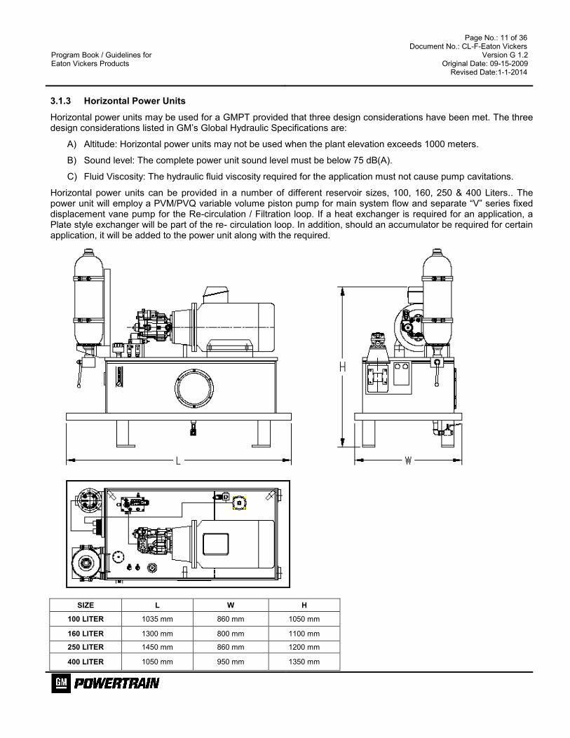
3.1.3 Horizontal Power Units
Horizontal power units may be used for a GMPT provided that three design considerations have been met. The three design considerations listed in GM’s Global Hydraulic Specifications are:
A) Altitude: Horizontal power units may not be used when the plant elevation exceeds 1000 meters.
B) Sound level: The complete power unit sound level must be below 75 dB(A).
C) Fluid Viscosity: The hydraulic fluid viscosity required for the application must not cause pump cavitations.
Horizontal power units can be provided in a number of different reservoir sizes, 100, 160, 250 & 400 Liters.. The power unit will employ a PVM/PVQ variable volume piston pump for main system flow and separate “V” series fixed displacement vane pump for the Re-circulation / Filtration loop. If a heat exchanger is required for an application, a Plate style exchanger will be part of the re- circulation loop. In addition, should an accumulator be required for certain application, it will be added to the power unit along with the required.
SIZE L W H
100 LITER 1035 mm 860 mm 1050 mm
160 LITER 1300 mm 800 mm 1100 mm
250 LITER 1450 mm 860 mm 1200 mm
400 LITER 1050 mm 950 mm 1350 mm

Program Book / Guidelines for Eaton Vickers Products
Page No.: 12 of 36 Document No.: CL-F-Eaton Vickers
Version G 1.2 Original Date: 09-15-2009
Revised Date:1-1-2014
Sound Spec: Less than 75 dB(A) Ports: ISO 1179-1 (G thread) Options: Accumulator circuit, heat exchanger circuit
Fill point: H6-63 BSPP Labels: Per GM Spec. Tubing & Fittings: Trivalent Chrome metric tubing & metric flareless fittings per GM spec.
100 L 160 L 250L
400L
Main Pump, Variable Displacement
PVM018ER17DS05AAC2314000000A
PVQ32MBR00SENS21CG14D21S3
PVM045ER17DS08AAC2314000000A
PVM081ER18FS08AAC2314000000A
Theo. Flow @1000 RPM 18.0 LPM 32.9 LPM 45.0 LPM 80.9 LPM
Theo. Flow @ 1200 RPM 21.6 LPM 39.5 LPM 54.0 LPM 97.1 LPM
Theo. Flow @ 1500 RPM 27.0 LPM 52.6 LPM 67.6 LPM 121.4 LPM
Pump Drive Speed
The electric motor drive speeds for the regions are: 1000 RPM for Europe, 1200 RPM for North America, 1500 RPM for China, Asia and South America. For China, Asia and South America 1500 RPM electric motors should be used unless the max. Sound level of 75dB(A) cannot be achieved. In this case, 1000-RPM electric motors may be used; however, the GM country unit must be consulted.
Electric Motor The machine builder should confirm the G.M. plant location to determine the exact motor voltage requirements.
Return Filter DIN Filters should be used for all regions except North America. For North America HF4 series return filters should be used.
Temperature Switch TR7430 TR7430 TR7430 TR7430
Level Switch LK7023 LK7023 LK7023 LK7023
Pressure Switch PN7001 PN7001 PN7001 PN7001
Program Book / Guidelines for Eaton Vickers Products
Page No.: 13 of 36 Document No.: CL-F-Eaton Vickers
Version G 1.2 Original Date: 09-15-2009
Revised Date:1-1-2014
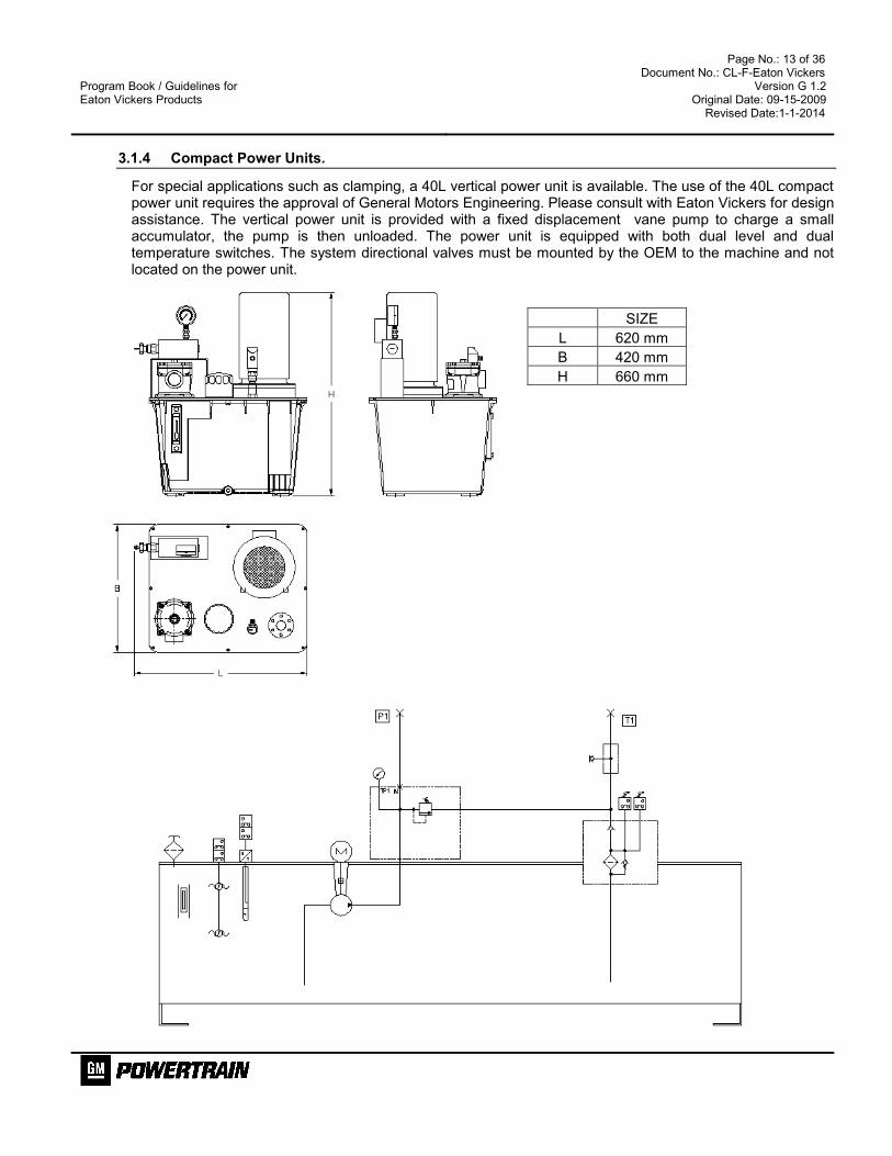
3.1.4 Compact Power Units.
For special applications such as clamping, a 40L vertical power unit is available. The use of the 40L compact power unit requires the approval of General Motors Engineering. Please consult with Eaton Vickers for design assistance. The vertical power unit is provided with a fixed displacement vane pump to charge a small accumulator, the pump is then unloaded. The power unit is equipped with both dual level and dual temperature switches. The system directional valves must be mounted by the OEM to the machine and not located on the power unit.
SIZE
L 620 mm
B 420 mm
H 660 mm

Program Book / Guidelines for Eaton Vickers Products
Page No.: 14 of 36 Document No.: CL-F-Eaton Vickers
Version G 1.2 Original Date: 09-15-2009
Revised Date:1-1-2014
3.1.5 In-Line Pressure Filters
In- Line Pressure (HF*)
FOR INDICATOR REF : 3.1.7

Program Book / Guidelines for Eaton Vickers Products
Page No.: 15 of 36 Document No.: CL-F-Eaton Vickers
Version G 1.2 Original Date: 09-15-2009
Revised Date:1-1-2014
In-Line Pressure DIN
FOR INDICATOR REF : 3.1.7

Program Book / Guidelines for Eaton Vickers Products
Page No.: 16 of 36 Document No.: CL-F-Eaton Vickers
Version G 1.2 Original Date: 09-15-2009
Revised Date:1-1-2014
3.1.6 In - Tank Return Filters
In-Tank (HF*)
FOR INDICATOR REF : 3.1.7

Program Book / Guidelines for Eaton Vickers Products
Page No.: 17 of 36 Document No.: CL-F-Eaton Vickers
Version G 1.2 Original Date: 09-15-2009
Revised Date:1-1-2014
In-Tank DIN
FOR INDICATOR REF : 3.1.7

Program Book / Guidelines for Eaton Vickers Products
Page No.: 18 of 36 Document No.: CL-F-Eaton Vickers
Version G 1.2 Original Date: 09-15-2009
Revised Date:1-1-2014
3.1.7 Filter Electrical Indicators.
Filter Series Hydac Model code Hydac Part Number
HF3P Pressure filters VD 5 LZ. 0 / BO 01265195
DHP DIN Pressure filters VD 5 LZ. 0 / BO 01265195
DRT DIN Tank top Return filters VR 2 LZ. 0 / BO 012654422
HF4RT Tank top Return filters VMF 2 LZ. 1 / BO 02074114

Program Book / Guidelines for Eaton Vickers Products
Page No.: 19 of 36 Document No.: CL-F-Eaton Vickers
Version G 1.2 Original Date: 09-15-2009
Revised Date:1-1-2014
3.2 DIRECTIONAL VALVES
3.2.1 NG6 (D03) Four-Way Directional Control Valves
Subplate mounted, 24 V DC, NBR seals, M12 connector on each Sol., pin configuration: Pin 1 & 2 not used, Pin 3 – 0volt, Pin 4 – 24Volt.
Symbol Model Number & Description Part Number
F6-DG4V-3-6C-M-KUPM4L-D7-H7-60 P = 30 Watts
02-400431
F6-DG4V-3-6C-M-KUPM4L-D7-HL7-60 P = 18 Watts
02-400432
F6-DG4V-3-6C208-M-KUPM4L-D7-H7-60 Soft shift, P = 30 Watts
02-400433
F6-DG4V-3-33C-M-KUPM4L-D7-H7-60 P = 30 Watts
02-400434
F6-DG4V-3-33C-M-KUPM4L-D7-HL7-60 P = 18 Watts
02-400435
F6-DG4V-3-33C208-M-KUPM4L-D7-H7-60 Soft shift, P = 30 Watts
02-400436
F6-DG4V-3-2A-M-KUPM4L-D7-H7-60 P = 30 Watts
02-400425
F6-DG4V-3-2A-M-KUPM4L-D7-HL7-60 P = 18 Watts
02-400426
F6-DG4V-3-2A208-M-KUPM4L-D7-H7-60 Soft shift, P = 30 Watts
02-400427
†
F6-DG4V-3-2N-M-KUPM4L-D7-H7-60 P = 30 Watts
02-400428
F6-DG4V-3-2N-M-KUPM4L-D7-HL7-60 P = 18 Watts
02-400429
F6-DG4V-3-2A208-M-KUPM4L-D7-H7-60 Soft shift, P = 30 Watts
02-400430
3.2.2 Single Stage NG10 (D05) Four-Way Directional Control Valves
Subplate mounted, 24 V DC, NBR seals, M12 connector on each Sol., pin configuration: Pin 1 & 2 not used, Pin 3 – 0volt, Pin 4 – 24Volt.
Symbol Model Number & Description Part Number
F6-DG4V4-016C-M-KUPM4L-D7-H-5-10 P = 45 Watts
02-400441
F6-DG4V4-016C-M-KUPM4L-D7-HL-4-10 P = 30 Watts
02-400442
F6-DG4V4-0133C-M-KUPM4L-D7-H-5-10 P = 45 Watts
02-400443
F6-DG4V4-0133C-M-KUPM4L-D7-HL-4-10 P = 30 Watts
02-400444
F6-DG4V4-012A-M-KUPM4L-D7-H-5-10 P = 45 Watts
02-400437
F6-DG4V4-012A-M-KUPM4L-D7-HL-4-10 P = 30 Watts
02-400438
†
F6-DG4V4-012N-M-KUPM4L-D7-H-5-10 P = 45 Watts
02-400439
F6-DG4V4-012N-M-KUPM4L-D7-HL-4-10 P = 30 Watts
02-400440

Program Book / Guidelines for Eaton Vickers Products
Page No.: 20 of 36 Document No.: CL-F-Eaton Vickers
Version G 1.2 Original Date: 09-15-2009
Revised Date:1-1-2014
3.2.3 Two Stage NG10 (D05) Four-Way Directional Control Valves
Subplate mounted, 24 V DC, P=18 Watts, NBR seals, M12 connector on each Sol., pin configuration: Pin 1 & 2 not used, Pin 3 – 0volt, Pin 4 – 24Volt.
Symbol Model Number Part Number
F6-DG5V-5-6C-M-KUPM4L-D7-HL7-10 02-400447
F6-DG5V-5-33C-M-KUPM4L-D7-HL7-10 02-400448
F6-DG5V-5-2A-M-KUPM4L-D7-HL7-10 02-400445
†
F6-DG5V-5-2N-M-KUPM4L-D7-HL7-10 02-400446
3.2.4 NG16 (D07) Four-Way Directional Control Valves
Subplate mounted, 24 V DC, P=18 Watts, NBR seals, M12 connector on each Sol., pin configuration: Pin 1 & 2 not used, Pin 3 – 0volt, Pin 4 – 24Volt.
Symbol Model Number Part Number
F6-DG5V-7-6C-M-KUPM4L-D7-HL7-10 02-400451
F6-DG5V-7-33C-M-KUPM4L-D7-HL7-10 02-400452
F6-DG5V-7-2A-M-KUPM4L-D7-HL7-30 02-400449
†
F6-DG5V-7-2N-M-KUPM4L-D7-HL7-30 02-400450
Program Book / Guidelines for Eaton Vickers Products
Page No.: 21 of 36 Document No.: CL-F-Eaton Vickers
Version G 1.2 Original Date: 09-15-2009
Revised Date:1-1-2014
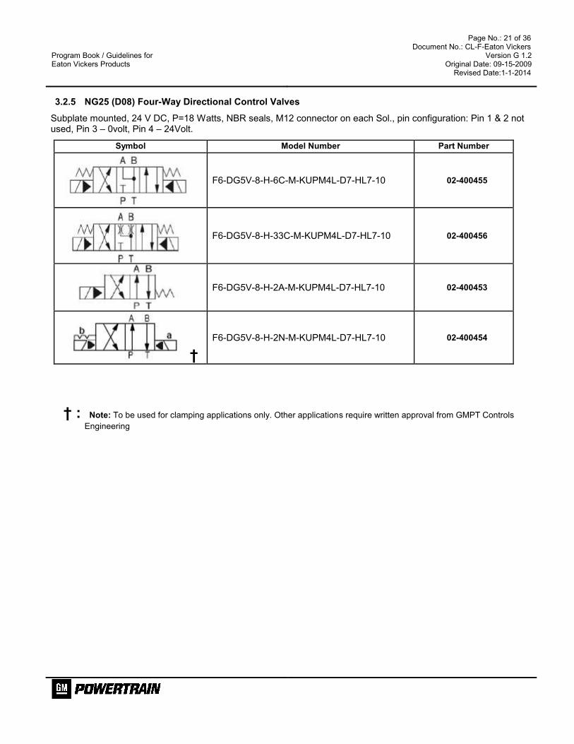
3.2.5 NG25 (D08) Four-Way Directional Control Valves
Subplate mounted, 24 V DC, P=18 Watts, NBR seals, M12 connector on each Sol., pin configuration: Pin 1 & 2 not used, Pin 3 – 0volt, Pin 4 – 24Volt.
Symbol Model Number Part Number
F6-DG5V-8-H-6C-M-KUPM4L-D7-HL7-10 02-400455
F6-DG5V-8-H-33C-M-KUPM4L-D7-HL7-10 02-400456
F6-DG5V-8-H-2A-M-KUPM4L-D7-HL7-10 02-400453
†
F6-DG5V-8-H-2N-M-KUPM4L-D7-HL7-10 02-400454
† : Note: To be used for clamping applications only. Other applications require written approval from GMPT Controls
Engineering

Program Book / Guidelines for Eaton Vickers Products
Page No.: 22 of 36 Document No.: CL-F-Eaton Vickers
Version G 1.2 Original Date: 09-15-2009
Revised Date:1-1-2014
3.3 MODULAR SANDWICH VALVE.
3.3.1 NG6 (D03) Modular Sandwich Modules.
Symbol Model Number & Description Part Number
Dual Flow control Module Meter out
On port A & B. DGMFN-3-Y-A1W-B1W-41
694411
Flow control Module Meter out
On port B. DGMFN-3-Y-B1W-41
02-138526
Flow control Module Meter out
On port A. DGMFN 3 Y A1W 41
02-138527
Dual P.O. Check Module On Port A & B Pilot Ratio 3:1
DGMPC 3 ABK BAK 41
694400
A Port P.O Check Module On Port A
Pilot Ratio 3:1 DGMPC 3 ABK 41
870024
B Port P.O Check Module On Port B
Pilot Ratio 3:1 DGMPC 3 BAK 41
870023
“P” Port Check Module 0.5 bar (8 psi) Spring DGMDC 3 Y PK 41
694415
“P” Port Pressure Reducing / Releiving Module
30 bar max.DGMX23PPAWB40 870021
80 bar max. DGMX23PPBWB40 870036
120 bar maxDGMX23PPCWB40 870037

Program Book / Guidelines for Eaton Vickers Products
Page No.: 23 of 36 Document No.: CL-F-Eaton Vickers
Version G 1.2 Original Date: 09-15-2009
Revised Date:1-1-2014
“A” Port Pressure Reducing / Releiving Module
80 bar max. DGMX23PABWB40 870031
120 bar maxDGMX23PACWB40 870032
“B” Port Pressure Reducing / Releiving Module
80 bar max. DGMX23PBBWB40 870047
120 bar maxDGMX23PBCWB40 8700267
P to T Pressure Relief Module
50 bar max DGMC 3 PT AW 41 02-108132
100 bar max DGMC 3 PT BW 41 02-147590
200 bar max DGMC 3 PT CW 41 870233
B to T Pressure Relief Module
50 bar max DGMC 3 BT AW 41 871703
100 bar max DGMC 3 BT BW 41 02-108538
200 bar max DGMC 3 BT CW 41 870257
A to T Pressure Relief Module
50 bar max DGMC 3 AT AW 41 02-138107
100 bar max DGMC 3 AT BW 41 02-138108
200 bar max DGMC 3 AT CW 41 02-139196
3.3.2 NG10 (D05) Modular Sandwich Modules.
Symbol Model Number & Description Part Number
Dual Flow control Module Meter out
On port A & B. DGMFN 5 Y A1W B1W 30
868884
Flow control Module Meter out
On port B. DGMFN 5 Y B1W 30
02-140612
Flow control Module Meter out
On port A. DGMFN 5 Y A1W 30
867334

Program Book / Guidelines for Eaton Vickers Products
Page No.: 24 of 36 Document No.: CL-F-Eaton Vickers
Version G 1.2 Original Date: 09-15-2009
Revised Date:1-1-2014
Dual P.O. Check Module On Port A & B Pilot Ratio 3:1
DGMPC 5 ABK BAK 30
867364
P.O. Check Module On Port A
Pilot Ratio 3:1 DGMPC 5 ABK 30
867339
P.O. Check Module On Port B
Pilot Ratio 3:1 DGMPC 5 BAK 30
867340
“P” Port Check Module
1bar (15 psi)
DGMDC 5 Y PK 30
867341
“T” Port Check Module
1bar (15 psi)
DGMDC 5 X TK 30
867342
“P” Port Pressure Reducing / Releiving Module
50 bar max. DGMX2 5 PP AW B 30 879343
100 bar max. DGMX2 5 PP BW B 30 868314
200 bar max. DGMX2 5 PP FW B 30 880553
“A” Port Pressure Reducing / Releiving Module
50 bar max. DGMX2 5 PA AW B 30 879344
100 bar max. DGMX2 5 PA BW B 30 868316
200 bar max. DGMX2 5 PA FW B 30 02-101968

Program Book / Guidelines for Eaton Vickers Products
Page No.: 25 of 36 Document No.: CL-F-Eaton Vickers
Version G 1.2 Original Date: 09-15-2009
Revised Date:1-1-2014
“B” Port Pressure Reducing / Releiving Module
50 bar max. DGMX2 5 PB AW B 30 880554
100 bar max. DGMX2 5 PB BW B 30 868317
200 bar max. DGMX2 5 PB FW B 30 02-145043
P to T Pressure Relief Module
50 bar : DGMC 5 PT AW 30 879341
100 bar : DGMC 5 PT BW 30 868650
200 bar : DGMC 5 PT FW 30 879342
A to T Pressure Relief Module
50 bar : DGMC 5 AT AW 30 02-336089
100 bar : DGMC 5 AT BW 30 868651
200 bar : DGMC 5 AT FW 30 02-149394
B to T Pressure Relief Module
50 bar : DGMC 5 BT AW 30 868651
100 bar : DGMC 5 BT BW 30 868652
200 bar : DGMC 5 BT FW 30 02-127594
3.3.3 NG16 (D07) Modular Sandwich Modules.
Symbol Model Number & Description Part Number
Dual Flow control Module Meter out
On port A & B. DGMFN 7 Y A2W B2W 30
02-413078
Dual P.O. Check Module On Port A & B
DGMPC 7 ABK BAK 30
02-413103
P.O. Check Module On Port A
DGMPC 7 ABK 30 02-413102

Program Book / Guidelines for Eaton Vickers Products
Page No.: 26 of 36 Document No.: CL-F-Eaton Vickers
Version G 1.2 Original Date: 09-15-2009
Revised Date:1-1-2014
P.O. Check Module On Port B
DGMPC 7 BAK 30 02-413106
3.3.4 NG25 (D08) Modular Sandwich Modules.
Symbol Model Number & Description Part Number
Dual Flow control Module Meter out
On port A & B. DGMN H8 Y A2W B2W 30
02-413088
Dual P.O. Check Module On Port A & B
DGMPC H8 ABK BAK 30 02-413055
P.O. Check Module On Port A
DGMPC H8 ABK 30 02-413112
P.O. Check Module On Port B
DGMPC H8 BAK 30 02-413114

Program Book / Guidelines for Eaton Vickers Products
Page No.: 27 of 36 Document No.: CL-F-Eaton Vickers
Version G 1.2 Original Date: 09-15-2009
Revised Date:1-1-2014
3.4 INLINE CHECK VALVES.
Model Code Cracking Pressure , Port Size Flow in
lpm Part Number
DT8P1-02-05-10-UB 0.3 bar (5 psi )cracking, G ¼ 12 796121
DT8P1-02-30-10-UB 2 bar(30 psi) cracking, G ¼ 12 796125
DT8P1-03-05-10-UB 0.3 bar (5 psi )cracking, G 3/8 30 465451
DT8P1-03-30-10-UB 2 bar(30 psi) cracking, G 3/8 30 465605
DT8PI-06-05-11-ENB 0.3 bar (5 psi )cracking, G ¾ 76 796127
DT8PI-06-30-11-ENB 2 bar(30 psi) cracking, G ¾ 76 796131
DT8PI-10-05-11-ENB 0.3 bar (5 psi )cracking, G1¼ 190 796133
DT8PI-10-30-11-ENB 2 bar(30 psi) cracking, G 1¼ 190 796137
Waltersheid Check valve Model Code Cracking Pressure , Pipe Size Flow in lpm Part Number
RS 8 S 0.5 bar(7 psi) cracking, 8 mm OD 20 067401 + 032431
RS 10 S 0.5 bar(7 psi) cracking, 10 mm OD 30 067402 + 032431
RS 16 S 0.5 bar(7 psi) cracking, 16 mm OD 50 025190 + 032438
RS 20 S 0.5 bar(7 psi) cracking, 20 mm OD 150 067404 + 032445
RS 25 S 0.5 bar(7 psi) cracking, 25 mm OD 150 067405 + 032445
RS 30 S 0.5 bar(7 psi) cracking, 30 mm OD 200 067406 + 032451
RS 38 S 0.5 bar(7 psi) cracking, 30 mm OD 200 067407 + 032457
Program Book / Guidelines for Eaton Vickers Products
Page No.: 28 of 36 Document No.: CL-F-Eaton Vickers
Version G 1.2 Original Date: 09-15-2009
Revised Date:1-1-2014
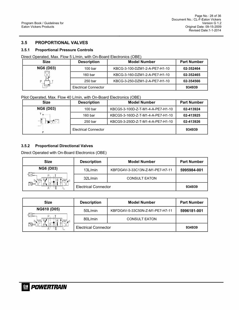
3.5 PROPORTIONAL VALVES
3.5.1 Proportional Pressure Controls
Direct Operated, Max. Flow 5 L/min, with On-Board Electronics (OBE)
Size Description Model Number Part Number
NG6 (D03)
100 bar KBCG-3-100-DZM1-2-A-PE7-H1-10 02-352464
160 bar KBCG-3-160-DZM1-2-A-PE7-H1-10 02-352465
250 bar KBCG-3-250-DZM1-2-A-PE7-H1-10 02-354566
Electrical Connector 934939
Pilot Operated, Max. Flow 40 L/min, with On-Board Electronics (OBE)
Size Description Model Number Part Number
NG6 (D03)
100 bar KBCG5-3-100D-Z-T-M1-4-A-PE7-H1-10 02-413924
160 bar KBCG5-3-160D-Z-T-M1-4-A-PE7-H1-10 02-413925
250 bar KBCG5-3-250D-Z-T-M1-4-A-PE7-H1-10 02-413926
Electrical Connector 934939
3.5.2 Proportional Directional Valves
Direct Operated with On-Board Electronics (OBE)
Size Description Model Number Part Number
NG6 (D03)
13L/min KBFDG4V-3-33C13N-Z-M1-PE7-H7-11 5995984-001
32L/min CONSULT EATON
Electrical Connector 934939
Size Description Model Number Part Number
NG610 (D05)
50L/min KBFDG4V-5-33C50N-Z-M1-PE7-H7-11 5996181-001
80L/min CONSULT EATON
Electrical Connector 934939

Program Book / Guidelines for Eaton Vickers Products
Page No.: 29 of 36 Document No.: CL-F-Eaton Vickers
Version G 1.2 Original Date: 09-15-2009
Revised Date:1-1-2014
3.6 ACCUMULATORS ¼ – 13.2 Gallons (1 – 50 Liters)
Diaphragm – Type Accumulators
Volume Pressure
Rating
Ports
ISO 1179-1
G thread
Hydac Model Code
1 Liter 210 bar G ½ SB0 210 1 E1 /112 ** 210 AK
Bottom Repairable Bladder Accumulators
Volume Pressure
Rating
Ports
ISO 1179-1
G thread
Hydac Model Code
4 Liter 330 bar G 1¼ SB 330 4 A1 / 112 ** 330 A
6 Liters 330 bar G 1¼ SB 330 6 A1 / 112 ** 330 A
10 Liters 330 bar G 2 SB 330 10 A1 / 112 ** 330 A
20 Liters 330 bar G 2 SB 330 20 A1 / 112 ** 330 A
32 Liters 330 bar G 2 SB 330 32 A1 / 112 ** 330 A
50 Liters 330 bar G 2 SB 330 50 A1 / 112 ** 330 A
Above 50 liters
Use Piston Accumulators. Consult Eaton for further Details
Accessories Volume Qty Part Number
Clamp 1 ltr 1 100AV00048A
Clamp 4 … 6 ltr 2 100AV00041A
Clamp 10 ltr 1 100AV00042A
Clamp 20 … 50 ltr 2 100AV00042A
Support Bracket w/ Ring 4 … 6 Liters 1 100AV00054A
Support Bracket w/ Ring 10…32 Liters 1 100AV00055A
Charging kit 100AV00093A
** Note: The accumulator model codes may require a different suffix code dependant upon the country where the accumulator is being shipped. For the U.S. and Mexico this is an ASME suffix code, Ontario Canada requires ASME plus TSSA certification, CE for Europe, SELO for China and NR-13 for Brazil. Other countries may have different certification requirements and the suffix code may change. Please check with Eaton Vickers for the requirements of the final destination country.

Program Book / Guidelines for Eaton Vickers Products
Page No.: 30 of 36 Document No.: CL-F-Eaton Vickers
Version G 1.2 Original Date: 09-15-2009
Revised Date:1-1-2014
3.7 ACCUMULATOR SAFETY BLOCKS
Accumulator Size Size –Model Code
Ports
ISO 1179-1
G thread
Part Numbers
1 Liter NG 10 – ESS 10E 16Y1-N250A-S30- L G 1/2 100AV00169A
4 to 6 Liters NG 10 – ESS 10E 16Y1-N250A-S12- L G 1¼ 100AV00170A
10 to 20 Liters NG 20 – ESS 20E16Y1-N250A-S13- L G 2 100AV00171A
34 to 50 Liters NG 32 – ESS 32E16Y1-N250A-S309- L G 2 100AV00172A
Accessories Part Number
DIN-M12 Connector Equipped with Z diode and indicator light (DIN to M12 adapter to be added)
Part Number
VAG-029-3401 ( MENCOM )
The Accumulator Safety Blocks are used for safety, isolation and unloading of hydraulic accumulators. GMPT specifications require a safety block to be provided for each accumulator application. Each safety block is equipped with a manual isolation valve with locking handle, manual unloading valve, safety valve and a 24 V solenoid unloading valve.
Required per
GM spec.

Program Book / Guidelines for Eaton Vickers Products
Page No.: 31 of 36 Document No.: CL-F-Eaton Vickers
Version G 1.2 Original Date: 09-15-2009
Revised Date:1-1-2014
3.8 SUB PLATES
Steel or Ductile Iron Subplates with Metric Threads for Valve Bolt Down
Valve Pattern Port ISO 228 # MODEL CODE Description Part Numbers
NG6(D03) G 3/8 DGVM 3 10 R Bottom Ported 466730
NG10 (D05) G ½ E DGSM 01Y 10 R Bottom Ported 711921
NG16(D07) G 3/4 E DGVM 7X D 10 R Bottom Ported w/ X & Y Ports 984617
NG25(D08) G1 E DGVM 8X D 10 R Bottom Ported w/ X & Y Ports 788298
3.9 MANIFOLDS
Ductile Iron Manifolds with Bottom and Side Ports and Metric Valve Bolt Down Threads
SIZE Ports Nr. Of Stations MODEL CODE
NG6(D03)
A&B: G ½ P&T : G ¾
A B Test Points G1/4 ISO 228 Ports
P & T : Both Ends A& B : Bottom Face
Test Points : One on each side
2 PREMIUM - 3 2 LPR BP
3 PREMIUM - 3 3 LPR BP
4 PREMIUM - 3 4 LPR BP
5 PREMIUM - 3 5 LPR BP
6 PREMIUM - 3 6 LPR BP
7 PREMIUM - 3 7 LPR BP
Alternate manifolds (For North America or as requested by other regions)
A&B: G 3/4 P&T : G1
A B Test Points G1/4 ISO 228 Ports
P & T : Both Ends A& B : Bottom Face
Test Points : One on each side
2 DD03HPB023B
3 DD03HPB033B
4 DD03HPB043B
5 DD03HPB053B
6 DD03HPB063B
7 DD03HPB073B

Program Book / Guidelines for Eaton Vickers Products
Page No.: 32 of 36 Document No.: CL-F-Eaton Vickers
Version G 1.2 Original Date: 09-15-2009
Revised Date:1-1-2014
Ductile Iron Manifolds with Bottom and Side Ports and Metric Valve Bolt Down Threads
SIZE Ports Nr. Of Stations MODEL CODE
NG10 (D05)
A&B: G 1 P : G ¾ T : G 1
A B Test Points G1/4 ISO 228 Ports
P & T : Both Ends A& B : Bottom Face
Test Points : One on each side
2 MR K - 5 - 2 G
3 MR K - 5 - 3 G
4 MR K - 5 - 4 G
5 MR K - 5 - 5 G
6 MR K - 5 - 6 G
Alternate manifolds (For North America or as requested by other regions)
A&B: G 3/4 P&T : G 1
A B Test Points G1/4 ISO 228 Ports
P & T : Both Ends A& B : Bottom Face
Test Points : One on each side
2 DD05HPB023B
3 DD05HPB033B
4 DD05HPB043B
5 DD05HPB053B
6 DD05HPB063B
3.9.1 Cover Plates
Valve Pattern Description Model code
NG6 (D03) Cover Plate with
Metric Bolts & “O” Rings
MR C - 3 PA
Alternate for North America or as requested by other regions
D D03 COP G M
NG10 (D05) Cover Plate with
Metric Bolts & “O” Rings
MR C - 5 PA
Alternate for North America or as requested by other regions
D D05 COP G M
NG6 (D03) - NG10(D05)
D05(NG10) Adapter with Metric Bolts &
“O” Rings
MR A - 5 / 3
Alternate for North America or as requested by other regions
D D03 D05 VA AB M
Program Book / Guidelines for Eaton Vickers Products
Page No.: 33 of 36 Document No.: CL-F-Eaton Vickers
Version G 1.2 Original Date: 09-15-2009
Revised Date:1-1-2014
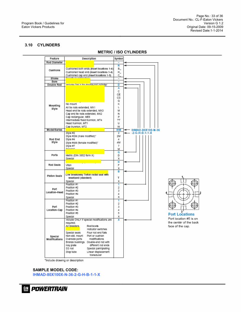
3.10 CYLINDERS
METRIC / ISO CYLINDERS
SAMPLE MODEL CODE:
IHMAD-80X100X-N-36-2-G-H-B-1-1-X

Program Book / Guidelines for Eaton Vickers Products
Page No.: 34 of 36 Document No.: CL-F-Eaton Vickers
Version G 1.2 Original Date: 09-15-2009
Revised Date:1-1-2014
Gland Drain Options: Gland drains are primarily used for long stroke cylinders (over 1 m) when extend speed exceeds retract speed. The Gland drain is used to return any accumulated fluid, between the rod seal and wiper, to tank. This is used in servo applications for ultra low leakage requirements or for remote visual monitoring of rod seal leakage for preventive maintenance purpose.

Program Book / Guidelines for Eaton Vickers Products
Page No.: 35 of 36 Document No.: CL-F-Eaton Vickers
Version G 1.2 Original Date: 09-15-2009
Revised Date:1-1-2014
3.11 WALTERSCHEID WALRING TUBE FITTINGS, AEROQUIP HOSE AND HANSEN COUPLERS
3.12 WALTERSCHEID WALRING TUBE FITTINGS
3.13 AEROQUIP HOSE
Data sheet: refer to hose catalogue
Program Book / Guidelines for Eaton Vickers Products
Page No.: 36 of 36 Document No.: CL-F-Eaton Vickers
Version G 1.2 Original Date: 09-15-2009
Revised Date:1-1-2014
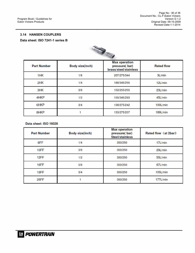
3.14 HANSEN COUPLERS
Data sheet: ISO 7241-1 series B


