PC-Based Multi-Format ANI & Emergency ANI Display Decoder · Kenwood’s FleetSync: Kenwood’s...
19
CAD-MF PC-Based Multi-Format ANI & Emergency ANI Display Decoder Manual Revision: 2010-05-25 Covers Firmware Revisions: CAD-MF: 1.0 & Higher Covers Software Revisions: CAD: 3.21 & Higher Covers Hardware Revisions: CAD: 219F 1
Transcript of PC-Based Multi-Format ANI & Emergency ANI Display Decoder · Kenwood’s FleetSync: Kenwood’s...

CAD-MF
PC-Based Multi-Format ANI & Emergency ANI Display Decoder
Manual Revision: 2010-05-25 Covers Firmware Revisions: CAD-MF: 1.0 & Higher Covers Software Revisions: CAD: 3.21 & Higher Covers Hardware Revisions: CAD: 219F
1
gskt
American Communication Systems, Inc.

HARDWARE SPECIFICATIONS Operating Voltage 7.5-15 VDC Operating Current 40 mA Maximum Current 1 A Operating Temperature -30 - +60 C Modem Baud Rate 1200 Audio Input Level (DTMF, MDC-1200, G-Star) 30 mV to 4.5 V p-p Audio Input Level (5-Tone) 400 mV to 4.5 V p-p Audio Input Level (FleetSync) 30 mV to 4.0 V p-p
SIGNALING SPECIFICATIONS
DTMF ANI Length Up to 8 digits ANI Timing 60/40 msec Digits Supported 0-9, *, #, A, B, C, D 5-Tone ANI Length Up to 8 digits ANI Timing Varies on Format Supported 5-Tone formats CCIR (1 or 2), DZVEI, DDZVEI, EEA, EIA, MODAT, NATEL, PCCIR, PDZVEI, PZVEI, ZVEI1 Digits Supported 0-9, A (Group), B, C, D, E (Repeat), F Harris’ G-Star (aka GE-Star) ANI Range 0001-16,383 ANI Timing 320 msec Motorola’s MDC-1200 ANI Length 4 digits ANI Timing ~180 msec Digits Supported 0000-DEEE FleetSync Unit ID Length 4 digits ANI Timing ~180 msec Unit ID Digits Supported 1000-3999 Baud Rate 1200
SYSTEM REQUIREMENTS
Operating System: Windows 98 SE, 2000, XP SP2 and higher, Vista (32 bit), 7 (32 bit) Processor: Pentium 2 or Higher Hard-Drive Space: Minimum 20 MB RAM: Minimum 256 MB USB Port is standard. Serial Port is available upon request. Serial to Ethernet Option is available (CAD Option B).
2
INSTALLATION OVERVIEW
1. Test the radio for functionality. 2. Connect the CAD modem to the radio per the Hardware Installation Section of this manual. 3. Program the CAD software and modem per the Product Programming Section of this manual. * Midian is not responsible for any damage/loss resulting from the use of Midian’s products.
GENERAL INFORMATION
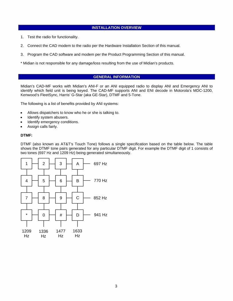
Midian’s CAD-MF works with Midian’s ANI-F or an ANI equipped radio to display ANI and Emergency ANI to identify which field unit is being keyed. The CAD-MF supports ANI and ENI decode in Motorola’s MDC-1200, Kenwood’s FleetSync, Harris’ G-Star (aka GE-Star), DTMF and 5-Tone. The following is a list of benefits provided by ANI systems: • Allows dispatchers to know who he or she is talking to. • Identify system abusers. • Identify emergency conditions. • Assign calls fairly. DTMF: DTMF (also known as AT&T’s Touch Tone) follows a single specification based on the table below. The table shows the DTMF tone pairs generated for any particular DTMF digit. For example the DTMF digit of 1 consists of two tones (697 Hz and 1209 Hz) being generated simultaneously.
1209 Hz
1336 Hz
1477 Hz
697 Hz
770 Hz
852 Hz
941 Hz
4 5 6
7 8 9
* 0 #
1 2 3 A
B
C
D
1633 Hz
3

5-Tone: In 5-Tone signaling the 0-9, B, C, D and F tones can be used as digits within a unit ID, such as 12345 or 9CB31. Please note that some manufacturers may reserve the B, C, D and F tones for special functions. However, the A and E tones work differently. The A tone is used as a group tone, which means that if 1234A is encoded then any unit ranging 12340 to 12349 will decode or if 123AA is encoded then any unit ranging from 12300 to 12399 will decode. The E tone is a repeat tone. For example when sending 12344 in CCIR the second 4 in the sequence will be an E tone (2110 Hz) rather than a second 4 tone (1358 Hz). A sequence of 12444 would send a 4 tone, followed by an E tone, followed by a 4 tone. This is done for reliability purposes. Please note that some manufacturers of radios and service monitors do not follow the standard using the repeat tone. If problems are experienced decoding sequences with repeat digits verify the frequencies the radio or service monitor are encoding. Another important note regarding 5-Tone signaling is about the tone timings. Under no circumstances should a tone time of less than 30 msec ever be used, as this greatly reduces the reliability of decoding the tones. Midian recommends using 33 msec or higher. Please see the following table for the frequencies and timings of the various 5-Tone protocols. The frequencies are shown in Hz and the times in milliseconds. Tone # Code
Digit CCIR 1 & 2
DZVEI DDZVEI EEA EIA MODAT NATEL PCCIR PDZVEI PZVEI ZVEI1
Tone 0 0 1981 2200 2400 1981 600 637.5 1633 1981 2200 2400 2400 Tone 1 1 1124 970 1060 1124 741 787.5 631 1124 970 1060 1060 Tone 2 2 1197 1060 1160 1197 882 937.5 697 1197 1060 1160 1160 Tone 3 3 1275 1160 1270 1275 1023 1087.5 770 1275 1160 1270 1270 Tone 4 4 1358 1270 1400 1358 1164 1237.5 852 1358 1270 1400 1400 Tone 5 5 1446 1400 1530 1446 1305 1387.5 941 1446 1400 1530 1530 Tone 6 6 1540 1530 1670 1540 1446 1537.5 1040 1540 1530 1670 1670 Tone 7 7 1640 1670 1830 1640 1587 1687.5 1209 1640 1670 1830 1830 Tone 8 8 1747 1830 2000 1747 1728 1837.5 1336 1747 1830 2000 2000 Tone 9 9 1860 2000 2200 1860 1869 1987.5 1477 1860 2000 2200 2200 Group A 2400 825 885 1055 2151 --- 1995 1050 825 970 2800
B 930 740 810 930 2433 --- 571 930 886 810 810 C 2247 2600 740 2400 2010 --- 2205 2400 2600 2800 970 D 991 885 680 991 2292 --- 2437 991 856 885 885
Repeat E 2110 2400 970 2110 459 487.5 1805 2110 2400 2600 2600 F 1055 680 2600 2247 1091 --- 2694 --- --- 680 680
Timing (msec)
100±15 70±15
70±15 70±15 40±4 33±0.5 40±5 70 100±10 70±15 70±15 70±15
Harris’ G-Star (aka GE-Star): G-Star was developed by General Electric (GE), because it was developed by GE many people refer to it as GE-Star. G-Star is a digital PSK signaling format supporting ANI’s from 0001-16,383 and an ANI timing of 320 msec. Motorola’s MDC-1200: Motorola’s MDC-1200 is a 1200 baud mobile data FFSK signaling format used by Motorola for ANI and Emergency ANI. MDC-1200 supports 4-digit ANI’s from 0000-DEEE and is approximately 180 msec in length. Kenwood’s FleetSync: Kenwood’s FleetSync is a 1200 baud mobile data FFSK signaling format used by Kenwood for ANI and Emergency ANI. Midian’s CAD-MF currently does not support 2400 baud Kenwood FleetSync.
4
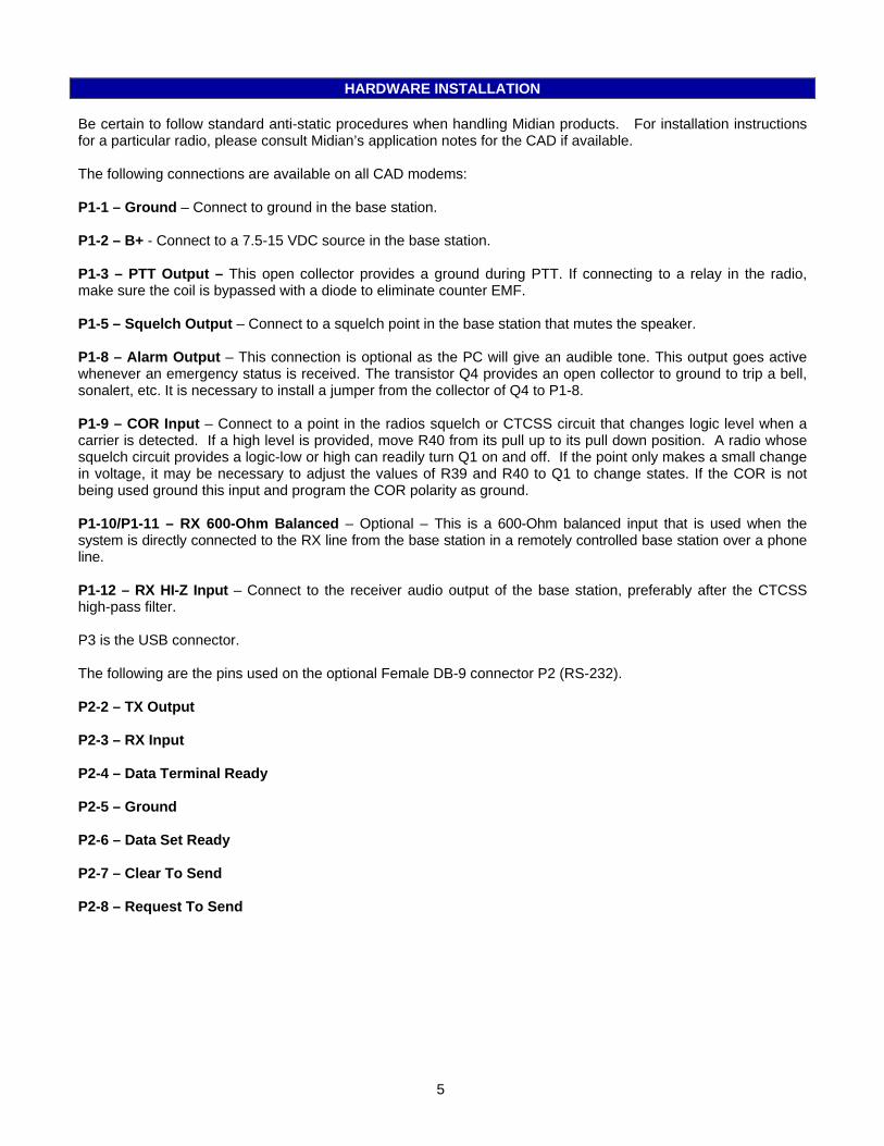
HARDWARE INSTALLATION Be certain to follow standard anti-static procedures when handling Midian products. For installation instructions for a particular radio, please consult Midian’s application notes for the CAD if available. The following connections are available on all CAD modems: P1-1 – Ground – Connect to ground in the base station. P1-2 – B+ - Connect to a 7.5-15 VDC source in the base station. P1-3 – PTT Output – This open collector provides a ground during PTT. If connecting to a relay in the radio, make sure the coil is bypassed with a diode to eliminate counter EMF. P1-5 – Squelch Output – Connect to a squelch point in the base station that mutes the speaker. P1-8 – Alarm Output – This connection is optional as the PC will give an audible tone. This output goes active whenever an emergency status is received. The transistor Q4 provides an open collector to ground to trip a bell, sonalert, etc. It is necessary to install a jumper from the collector of Q4 to P1-8. P1-9 – COR Input – Connect to a point in the radios squelch or CTCSS circuit that changes logic level when a carrier is detected. If a high level is provided, move R40 from its pull up to its pull down position. A radio whose squelch circuit provides a logic-low or high can readily turn Q1 on and off. If the point only makes a small change in voltage, it may be necessary to adjust the values of R39 and R40 to Q1 to change states. If the COR is not being used ground this input and program the COR polarity as ground. P1-10/P1-11 – RX 600-Ohm Balanced – Optional – This is a 600-Ohm balanced input that is used when the system is directly connected to the RX line from the base station in a remotely controlled base station over a phone line. P1-12 – RX HI-Z Input – Connect to the receiver audio output of the base station, preferably after the CTCSS high-pass filter. P3 is the USB connector. The following are the pins used on the optional Female DB-9 connector P2 (RS-232). P2-2 – TX Output P2-3 – RX Input P2-4 – Data Terminal Ready P2-5 – Ground P2-6 – Data Set Ready P2-7 – Clear To Send P2-8 – Request To Send
5
HARDWARE ALIGNMENT
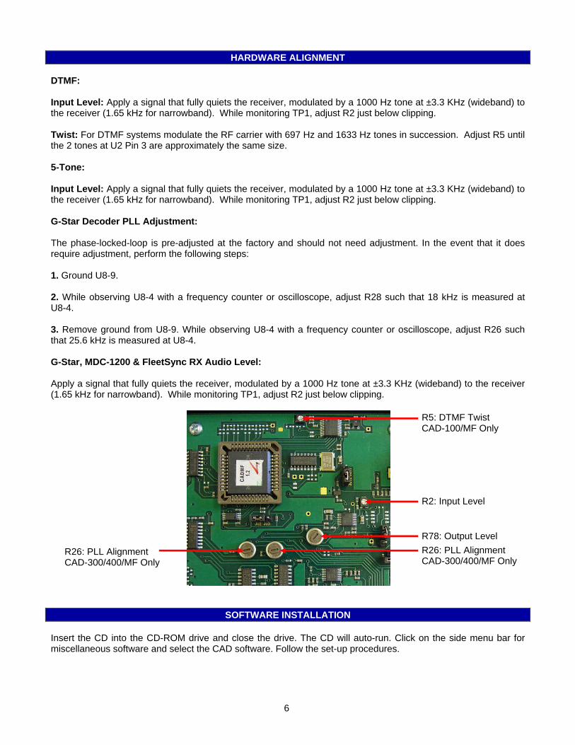
DTMF: Input Level: Apply a signal that fully quiets the receiver, modulated by a 1000 Hz tone at ±3.3 KHz (wideband) to the receiver (1.65 kHz for narrowband). While monitoring TP1, adjust R2 just below clipping. Twist: For DTMF systems modulate the RF carrier with 697 Hz and 1633 Hz tones in succession. Adjust R5 until the 2 tones at U2 Pin 3 are approximately the same size. 5-Tone: Input Level: Apply a signal that fully quiets the receiver, modulated by a 1000 Hz tone at ±3.3 KHz (wideband) to the receiver (1.65 kHz for narrowband). While monitoring TP1, adjust R2 just below clipping. G-Star Decoder PLL Adjustment: The phase-locked-loop is pre-adjusted at the factory and should not need adjustment. In the event that it does require adjustment, perform the following steps: 1. Ground U8-9. 2. While observing U8-4 with a frequency counter or oscilloscope, adjust R28 such that 18 kHz is measured at U8-4. 3. Remove ground from U8-9. While observing U8-4 with a frequency counter or oscilloscope, adjust R26 such that 25.6 kHz is measured at U8-4. G-Star, MDC-1200 & FleetSync RX Audio Level: Apply a signal that fully quiets the receiver, modulated by a 1000 Hz tone at ±3.3 KHz (wideband) to the receiver (1.65 kHz for narrowband). While monitoring TP1, adjust R2 just below clipping.
R5: DTMF Twist CAD-100/MF Only
R2: Input Level
R78: Output Level R26: PLL Alignment CAD-300/400/MF Only
R26: PLL Alignment CAD-300/400/MF Only
SOFTWARE INSTALLATION Insert the CD into the CD-ROM drive and close the drive. The CD will auto-run. Click on the side menu bar for miscellaneous software and select the CAD software. Follow the set-up procedures.
6
PRODUCT PROGRAMMING
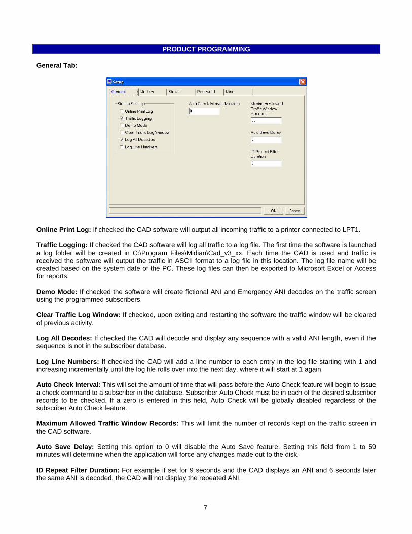
General Tab:
Online Print Log: If checked the CAD software will output all incoming traffic to a printer connected to LPT1. Traffic Logging: If checked the CAD software will log all traffic to a log file. The first time the software is launched a log folder will be created in C:\Program Files\Midian\Cad_v3_xx. Each time the CAD is used and traffic is received the software will output the traffic in ASCII format to a log file in this location. The log file name will be created based on the system date of the PC. These log files can then be exported to Microsoft Excel or Access for reports. Demo Mode: If checked the software will create fictional ANI and Emergency ANI decodes on the traffic screen using the programmed subscribers. Clear Traffic Log Window: If checked, upon exiting and restarting the software the traffic window will be cleared of previous activity. Log All Decodes: If checked the CAD will decode and display any sequence with a valid ANI length, even if the sequence is not in the subscriber database. Log Line Numbers: If checked the CAD will add a line number to each entry in the log file starting with 1 and increasing incrementally until the log file rolls over into the next day, where it will start at 1 again. Auto Check Interval: This will set the amount of time that will pass before the Auto Check feature will begin to issue a check command to a subscriber in the database. Subscriber Auto Check must be in each of the desired subscriber records to be checked. If a zero is entered in this field, Auto Check will be globally disabled regardless of the subscriber Auto Check feature. Maximum Allowed Traffic Window Records: This will limit the number of records kept on the traffic screen in the CAD software. Auto Save Delay: Setting this option to 0 will disable the Auto Save feature. Setting this field from 1 to 59 minutes will determine when the application will force any changes made out to the disk. ID Repeat Filter Duration: For example if set for 9 seconds and the CAD displays an ANI and 6 seconds later the same ANI is decoded, the CAD will not display the repeated ANI.
7
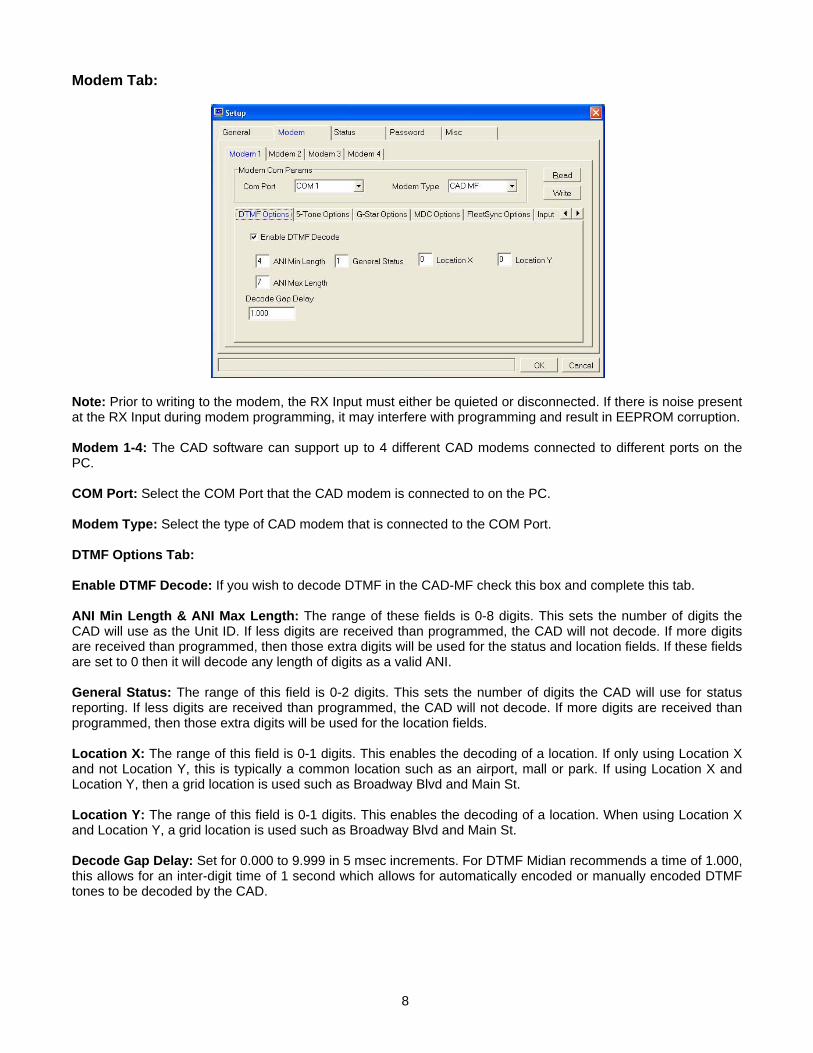
Modem Tab:
Note: Prior to writing to the modem, the RX Input must either be quieted or disconnected. If there is noise present at the RX Input during modem programming, it may interfere with programming and result in EEPROM corruption. Modem 1-4: The CAD software can support up to 4 different CAD modems connected to different ports on the PC. COM Port: Select the COM Port that the CAD modem is connected to on the PC. Modem Type: Select the type of CAD modem that is connected to the COM Port. DTMF Options Tab: Enable DTMF Decode: If you wish to decode DTMF in the CAD-MF check this box and complete this tab. ANI Min Length & ANI Max Length: The range of these fields is 0-8 digits. This sets the number of digits the CAD will use as the Unit ID. If less digits are received than programmed, the CAD will not decode. If more digits are received than programmed, then those extra digits will be used for the status and location fields. If these fields are set to 0 then it will decode any length of digits as a valid ANI. General Status: The range of this field is 0-2 digits. This sets the number of digits the CAD will use for status reporting. If less digits are received than programmed, the CAD will not decode. If more digits are received than programmed, then those extra digits will be used for the location fields. Location X: The range of this field is 0-1 digits. This enables the decoding of a location. If only using Location X and not Location Y, this is typically a common location such as an airport, mall or park. If using Location X and Location Y, then a grid location is used such as Broadway Blvd and Main St. Location Y: The range of this field is 0-1 digits. This enables the decoding of a location. When using Location X and Location Y, a grid location is used such as Broadway Blvd and Main St. Decode Gap Delay: Set for 0.000 to 9.999 in 5 msec increments. For DTMF Midian recommends a time of 1.000, this allows for an inter-digit time of 1 second which allows for automatically encoded or manually encoded DTMF tones to be decoded by the CAD.
8
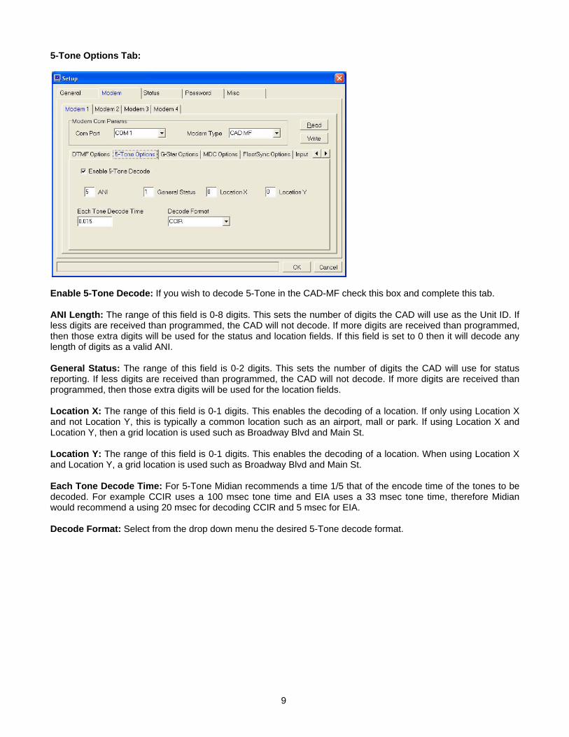
5-Tone Options Tab:
Enable 5-Tone Decode: If you wish to decode 5-Tone in the CAD-MF check this box and complete this tab. ANI Length: The range of this field is 0-8 digits. This sets the number of digits the CAD will use as the Unit ID. If less digits are received than programmed, the CAD will not decode. If more digits are received than programmed, then those extra digits will be used for the status and location fields. If this field is set to 0 then it will decode any length of digits as a valid ANI. General Status: The range of this field is 0-2 digits. This sets the number of digits the CAD will use for status reporting. If less digits are received than programmed, the CAD will not decode. If more digits are received than programmed, then those extra digits will be used for the location fields. Location X: The range of this field is 0-1 digits. This enables the decoding of a location. If only using Location X and not Location Y, this is typically a common location such as an airport, mall or park. If using Location X and Location Y, then a grid location is used such as Broadway Blvd and Main St. Location Y: The range of this field is 0-1 digits. This enables the decoding of a location. When using Location X and Location Y, a grid location is used such as Broadway Blvd and Main St. Each Tone Decode Time: For 5-Tone Midian recommends a time 1/5 that of the encode time of the tones to be decoded. For example CCIR uses a 100 msec tone time and EIA uses a 33 msec tone time, therefore Midian would recommend a using 20 msec for decoding CCIR and 5 msec for EIA. Decode Format: Select from the drop down menu the desired 5-Tone decode format.
9
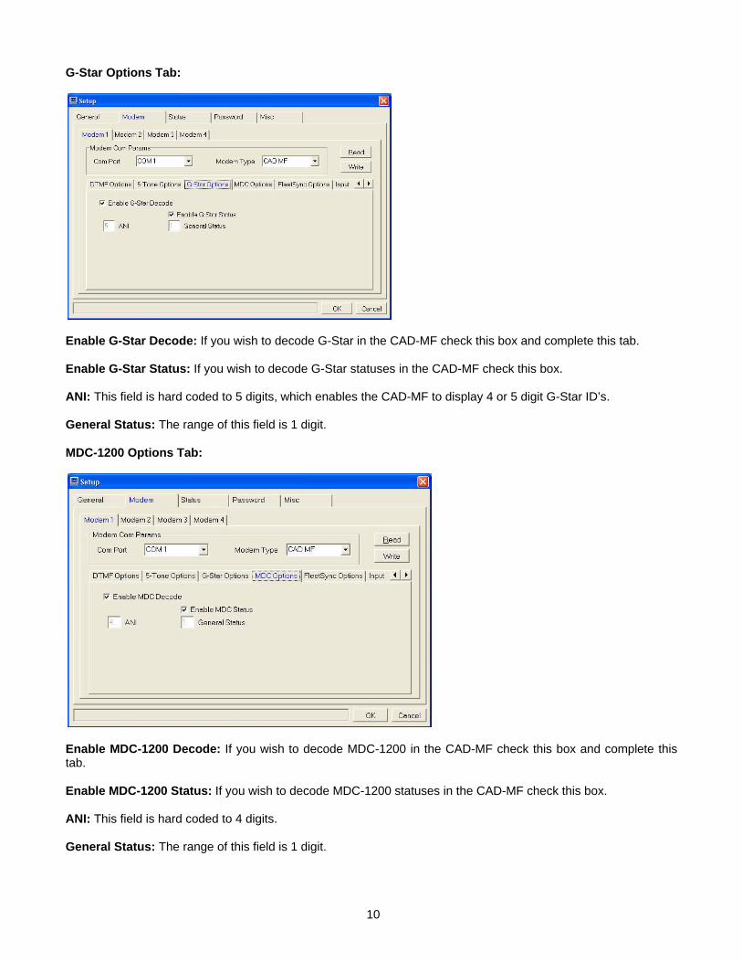
G-Star Options Tab:
Enable G-Star Decode: If you wish to decode G-Star in the CAD-MF check this box and complete this tab. Enable G-Star Status: If you wish to decode G-Star statuses in the CAD-MF check this box. ANI: This field is hard coded to 5 digits, which enables the CAD-MF to display 4 or 5 digit G-Star ID’s. General Status: The range of this field is 1 digit. MDC-1200 Options Tab:
Enable MDC-1200 Decode: If you wish to decode MDC-1200 in the CAD-MF check this box and complete this tab. Enable MDC-1200 Status: If you wish to decode MDC-1200 statuses in the CAD-MF check this box. ANI: This field is hard coded to 4 digits. General Status: The range of this field is 1 digit.
10
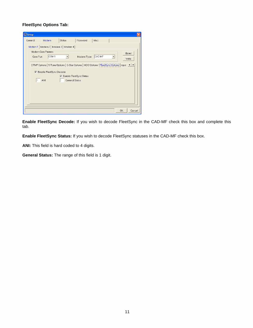
FleetSync Options Tab:
Enable FleetSync Decode: If you wish to decode FleetSync in the CAD-MF check this box and complete this tab. Enable FleetSync Status: If you wish to decode FleetSync statuses in the CAD-MF check this box. ANI: This field is hard coded to 4 digits. General Status: The range of this field is 1 digit.
11
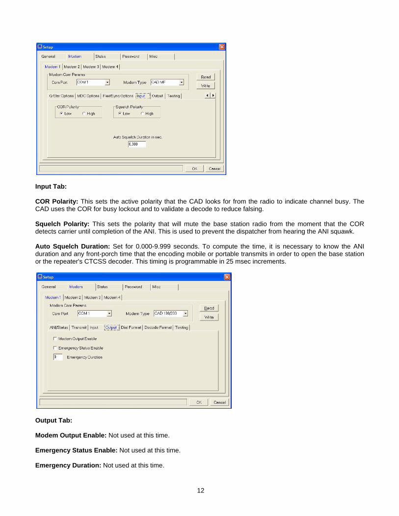
Input Tab: COR Polarity: This sets the active polarity that the CAD looks for from the radio to indicate channel busy. The CAD uses the COR for busy lockout and to validate a decode to reduce falsing. Squelch Polarity: This sets the polarity that will mute the base station radio from the moment that the COR detects carrier until completion of the ANI. This is used to prevent the dispatcher from hearing the ANI squawk. Auto Squelch Duration: Set for 0.000-9.999 seconds. To compute the time, it is necessary to know the ANI duration and any front-porch time that the encoding mobile or portable transmits in order to open the base station or the repeater's CTCSS decoder. This timing is programmable in 25 msec increments.
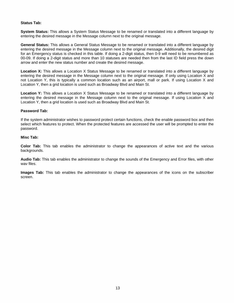
Output Tab: Modem Output Enable: Not used at this time. Emergency Status Enable: Not used at this time. Emergency Duration: Not used at this time.
12
Status Tab: System Status: This allows a System Status Message to be renamed or translated into a different language by entering the desired message in the Message column next to the original message. General Status: This allows a General Status Message to be renamed or translated into a different language by entering the desired message in the Message column next to the original message. Additionally, the desired digit for an Emergency status is checked in this table. If doing a 2-digit status, then 0-9 will need to be renumbered as 00-09. If doing a 2-digit status and more than 10 statuses are needed then from the last ID field press the down arrow and enter the new status number and create the desired message. Location X: This allows a Location X Status Message to be renamed or translated into a different language by entering the desired message in the Message column next to the original message. If only using Location X and not Location Y, this is typically a common location such as an airport, mall or park. If using Location X and Location Y, then a grid location is used such as Broadway Blvd and Main St. Location Y: This allows a Location X Status Message to be renamed or translated into a different language by entering the desired message in the Message column next to the original message. If using Location X and Location Y, then a grid location is used such as Broadway Blvd and Main St. Password Tab: If the system administrator wishes to password protect certain functions, check the enable password box and then select which features to protect. When the protected features are accessed the user will be prompted to enter the password. Misc Tab: Color Tab: This tab enables the administrator to change the appearances of active text and the various backgrounds. Audio Tab: This tab enables the administrator to change the sounds of the Emergency and Error files, with other wav files. Images Tab: This tab enables the administrator to change the appearances of the icons on the subscriber screen.
13

OPERATION
Main Window: File Menu: Here the user can print and import subscriber and other databases. Window Menu: Enables the user to change which windows are displayed on the screen. Traffic Log Window: The information in this screen will show system activity in chronological order with the most recent being at the top of the screen. Columns may be moved into any order by clicking and dragging the filed into the desired position. Columns can be added and removed from the display by going to Options > Traffic > Visible Columns.
Subscribers Window: Clicking a particular column header enables the dispatcher to sort the column. Columns may be moved into any order by clicking and dragging the filed into the desired position.
Add New Subscriber: Clicking on the add icon will open the subscriber information screen. Enter the user description and the desired ID’s. Please see the Subscribers section for details on adding new subscribers.
Edit Subscriber: Select the unit to be edited and click on the edit icon. The subscriber information screen will be opened, so the unit details can be edited.
Delete Subscriber: Select the unit to be deleted and click on the delete icon. This will permanently delete the unit from the database.
Subscriber Properties: TBD.
14

Modem Status Window: This screen will indicate if the modem is on-line or off-line and the version of the modem.
Alarm Status Window: This screen will display incoming emergency statuses in addition to them displaying in the traffic window.
Out of Service Window: When using the Query function this window will show if a subscriber did not respond.
Subscriber Response Window: When using the Query function this window will show if a subscriber responded. The response will also show in the traffic window.
15
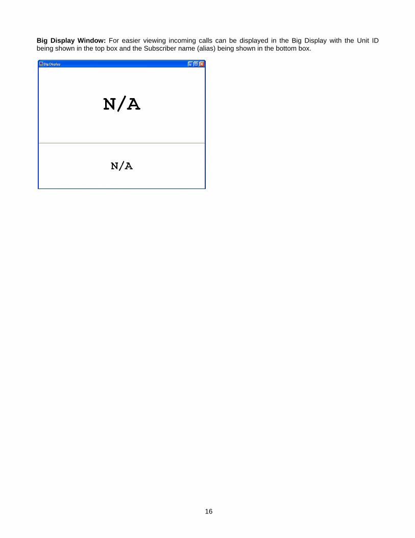
Big Display Window: For easier viewing incoming calls can be displayed in the Big Display with the Unit ID being shown in the top box and the Subscriber name (alias) being shown in the bottom box.
16
SUBSCRIBERS
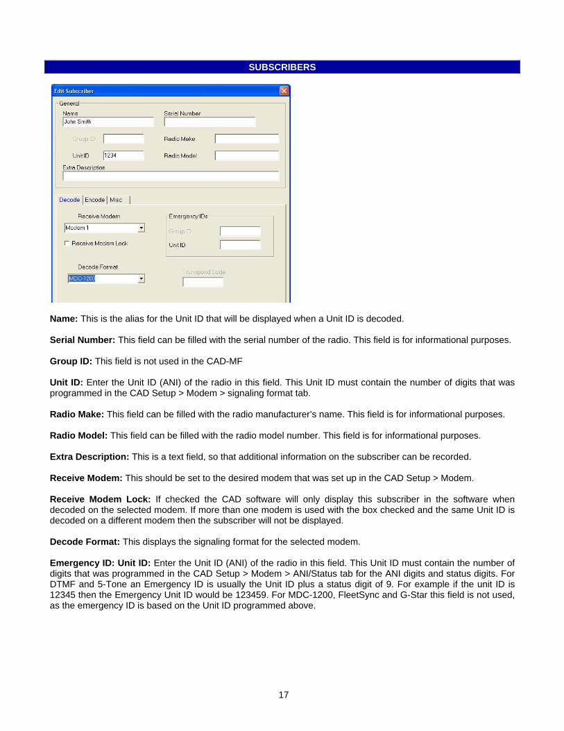
Name: This is the alias for the Unit ID that will be displayed when a Unit ID is decoded. Serial Number: This field can be filled with the serial number of the radio. This field is for informational purposes. Group ID: This field is not used in the CAD-MF Unit ID: Enter the Unit ID (ANI) of the radio in this field. This Unit ID must contain the number of digits that was programmed in the CAD Setup > Modem > signaling format tab. Radio Make: This field can be filled with the radio manufacturer’s name. This field is for informational purposes. Radio Model: This field can be filled with the radio model number. This field is for informational purposes. Extra Description: This is a text field, so that additional information on the subscriber can be recorded. Receive Modem: This should be set to the desired modem that was set up in the CAD Setup > Modem. Receive Modem Lock: If checked the CAD software will only display this subscriber in the software when decoded on the selected modem. If more than one modem is used with the box checked and the same Unit ID is decoded on a different modem then the subscriber will not be displayed. Decode Format: This displays the signaling format for the selected modem. Emergency ID: Unit ID: Enter the Unit ID (ANI) of the radio in this field. This Unit ID must contain the number of digits that was programmed in the CAD Setup > Modem > ANI/Status tab for the ANI digits and status digits. For DTMF and 5-Tone an Emergency ID is usually the Unit ID plus a status digit of 9. For example if the unit ID is 12345 then the Emergency Unit ID would be 123459. For MDC-1200, FleetSync and G-Star this field is not used, as the emergency ID is based on the Unit ID programmed above.
17
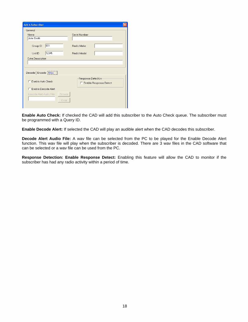
Enable Auto Check: If checked the CAD will add this subscriber to the Auto Check queue. The subscriber must be programmed with a Query ID. Enable Decode Alert: If selected the CAD will play an audible alert when the CAD decodes this subscriber. Decode Alert Audio File: A wav file can be selected from the PC to be played for the Enable Decode Alert function. This wav file will play when the subscriber is decoded. There are 3 wav files in the CAD software that can be selected or a wav file can be used from the PC. Response Detection: Enable Response Detect: Enabling this feature will allow the CAD to monitor if the subscriber has had any radio activity within a period of time.
18

19
TECHNICAL NOTES
Radio Compatibility: Midian has taken the utmost care to ensure the CAD integrates with the radio with minimal impact to the features of the radio. However, some features may not be available in the radio when a CAD is used. If a feature is not available, please contact Midian to see if the feature can be added. International Windows Versions: Even though Midian has worked to make this product internationally compliant, Midian recognizes that there may be additional issues to be resolved.
MIDIAN CONTACT INFORMATION
Midian Electronics Inc. 2302 East 22nd Street Tucson, Arizona 85713 USA Orders: 1-800-MIDIANS Phone: 520-884-7981 Fax: 520-884-0422 E-mail: [email protected] Web: http://www.midians.com/