Dealers Guide To FleetSync Programming Dealers Guide To... · 2016-10-23 · Kenwood Fleetsync...
28
11/01 Rev 2.0 1 Dealers guide to FleetSync Programming TK-280/380/480/481 TK-780/880/980/981 Version 2 radios ? Introduction This document covers the following subjects. Installation and use of the KPG49D 3.xx or better programming software. A FleetSync Feature list and a operational description of some of the Kenwood Fleetsync protocol features along with programming and interface information for the Communication ports in the 80 series radios. The TK-780/880/980/981 mobiles and the TK-280/380/480/481 portables setup is the same in most cases and will be referred to as the 80 series throughout this document. This document is meant to help the user get familiar with programming the radio and using the FleetSync features. This document also contains a series of simple programming exercises to help the user become familiar with programming the basic features of FleetSync. For more detailed information about the 80 series programming and operation, Refer to the Service Manual of the radio. For sales related applications refer to the FleetSync Application Guide. Table Of Contents What is FleetSync 2 FleetSync Installation Option 2 FleetSync Feature Sets 3 FleetSync Radio Versions 4 FleetSync Mobile PC Interface 5 KPG-49D Programming Software Installation 5 Programming For RF Communications 6 Exercise 1 Simplex Channel 6 Programming FleetSync Parameters 7 PTT ID Encode Using FleetSync 8 Exercise 2 PTT ID Encode 8 Decoding FleetSync PTT ID 10 Exercise 3 Caller ID Display Decode 10 Testing FleetSync ANI 12 FleetSync Timing Parameters 13 FleetSync Emergency 14 Exercise 4 Emergency Encode 14 FleetSync Emergency Decode 16 Exercise 5 Emergency Decode 16 Testing FleetSync Emergency 17 Man-Down Alert Encode 18 Man Down Alert Decode 18 CA-3 Tilt-Switch Installation 18 FleetSync Selective Calling 19 Exercise 6 Selective Call Encode 20 Exercise 7 Selective Call Decode 21 Testing Selective Call 23 FleetSync Status Messages 23 Exercise 8 Status Messaging Encode 24 Exercise 9 Status Messaging Decode 25 Testing Status Messaging 26 FleetSync Messages 27 FleetSync Short Messages 27 FleetSync Long Messages 27 Troubleshooting 27
-
Upload
trinhtuong -
Category
Documents
-
view
222 -
download
0
Transcript of Dealers Guide To FleetSync Programming Dealers Guide To... · 2016-10-23 · Kenwood Fleetsync...

11/01 Rev 2.0 1
Dealers guide to FleetSync ProgrammingTK-280/380/480/481 TK-780/880/980/981 Version 2 radios
? IntroductionThis document covers the following subjects. Installation and use of the KPG49D 3.xx or better programming software. A FleetSync Feature list and a operational description of some of the Kenwood Fleetsync protocol features along with programming and interface information for the Communication ports in the 80 series radios. The TK-780/880/980/981 mobiles and the TK-280/380/480/481 portables setup is the same in most cases and will be referred to as the 80 series throughout this document. This document is meant to help the user get familiar with programming the radio and using the FleetSync features.This document also contains a series of simple programming exercises to help the user become familiar with programming the basic features of FleetSync. For more detailed information about the 80 series programming and operation, Refer to the Service Manual of the radio. For sales related applications refer to the FleetSync Application Guide.
Table Of Contents
What is FleetSync 2FleetSync Installation Option 2FleetSync Feature Sets 3FleetSync Radio Versions 4FleetSync Mobile PC Interface 5KPG-49D Programming Software Installation 5Programming For RF Communications 6
Exercise 1 Simplex Channel 6Programming FleetSync Parameters 7PTT ID Encode Using FleetSync 8
Exercise 2 PTT ID Encode 8Decoding FleetSync PTT ID 10
Exercise 3 Caller ID Display Decode 10Testing FleetSync ANI 12
FleetSync Timing Parameters 13FleetSync Emergency 14
Exercise 4 Emergency Encode 14FleetSync Emergency Decode 16
Exercise 5 Emergency Decode 16Testing FleetSync Emergency 17
Man-Down Alert Encode 18Man Down Alert Decode 18CA-3 Tilt-Switch Installation 18FleetSync Selective Calling 19
Exercise 6 Selective Call Encode 20Exercise 7 Selective Call Decode 21Testing Selective Call 23
FleetSync Status Messages 23Exercise 8 Status Messaging Encode 24Exercise 9 Status Messaging Decode 25Testing Status Messaging 26
FleetSync Messages 27FleetSync Short Messages 27FleetSync Long Messages 27Troubleshooting 27

11/01 Rev 2.0 2
¨ What is FleetSync? Fleetsync is a signaling protocol integrated into Kenwood’s 80 series line of radios. The 80 series radios feature an on board modem capable of modulating a signal over the airwaves via two transceivers. This modem device is also capable of receiving commands and transmitting data to and from a PC’s serial port. This data can be used to send and receive data packets to control the radio or send and receive messages. FleetSync can operate in the Trunked or Conventional modes. FleetSync comes with two feature sets BASIC and ENHANCED. The Basic set is a standard feature of the radio. The Enhanced set is a dealer option. The list below shows the options available and their labor codes used when ordering the 80 series radios from Kenwood Communications order desk. See FleetSync Installation Options. For detailed information on FleetSync Applications see the FleetSync Application guide.
o Important Notes: The 80 series mobiles and/or accessories can be ordered from Kenwood pre-configured, tuned and tested via the labor codes shown below in this document. See Kenwood price pages for more information. All modifications and interfaces can be done by the user but requires some soldering. NOTE: As of the time of writing this document Kenwood is actively engaged in Licensing the peripheral products that the FleetSync Enhanced features require. We are currently providing the FleetSync technical documentation and Engineering OEM kits to companies interested in manufacturing FleetSync compatible products. We will notify our Reps and Dealers as these products become available.
o FleetSync Installation Options l L-875 Install FleetSync Enhanced options in 80 series Mobile. l L-918 Install Internal KCT -31 PC Interface Cable.
KCT-31 is used when connecting a 80 Series Mobile Radio to a PC for Short/Long Text Messaging and PC Control. FleetSync™ Enhanced Option must be installed in the radio to take advantage of these features Modify and Install Internal KCT-31 PC interface cable. (KGP46 can be used on COM 0 if no local Mic is required).
l L-845 CAE-3 Man-Down Tilt Switch Option l L-905 – L907 Order FleetSync Dealer enhanced retrofit kit (See Price Pages)

11/01 Rev 2.0 3
o FleetSync Feature Sets
FleetSync is a basic feature of all 80 series radios. The 80 series radios can be “Enhanced” in order to add PC control, Short and long text messaging and the GPS input /outputs of the radio. In most FleetSync Applications only the base will need to be Enhanced.
Basic Enhanced Digital PTT ID * * Selective Calling * * Group Calling * * Supervisor Calling * * Broadcast Calling * * Status Messaging * * Over The Air Stun, Kill and Revive * * PC Control 1 * Short Text Messaging (48 Characters) Note 1
* Long Text Messaging (1024 Characters) Note 1 * FleetSync™ GPS (AVL) Note 1 *
Note 1 – Additional Equipment Required

11/01 Rev 2.0 4
FleetSync™ Radio Versions Based on customer input Kenwood has made firmware and hardware design changes to the 80 series radios to add new features and improve upon existing features. The new design is called 80 series Version 2. These radios can be identified by the logos located on the radio front panel. The mobile units logo has been changed from a white Kenwood logo to a Orange logo. The portables Kenwood logo’s triangle [above the “W”] has been changed from white to orange. The Model/FCC ID label will read Ver- 2. The table below shows the changes made in version 2 compared with version 1.
Version 1 Version 2 Caller ID ( PTT ANI Decode )
N/A Standard
Selective Call ID Stack (Last 3 Calls)
N/A Standard
PTT ID Side Tone N/A Standard PTT ID TA Inhibit N/A Standard ID List Capacity 32 100 Status Message Capacity 32 50 ID / Status Access Rotary
Encoder C&D Keys
PTT ID Type On / Off Own/Sel
TX Inhibit Per ID / Status N/A Standard BCL On / Off Off / QT-
DQT Tone / Optional
Signaling
FleetSync™ Horn Alert Note 1
N/A Special Status 89
Emergency Man Down Note 1
N/A Special Status 98
Emergency Mode Disable
N/A Special Status 88
Emergency Locator Tones
N/A Before and After
Emergency
Com Port Configuration 1 For GPS 1 For
Messaging
Same as Version 1 or 1 for
Both Note 1 – Additional Equipment Required

11/01 Rev 2.0 5
o FleetSync Mobile PC Interfacing (Enhanced Required)
l The 80 series mobile radios have 3 Serial Data ports. COM 0, (Mic Jack), COM 1 (Internal),
COM 2 (Internal). The Comm ports are configured using the KPG49D programming software. See Labor codes above or call our Technical Support line for a copy of the interface instructions.
l The Com ports can be selected for five options: a. None (no function) b. REM (Remote control) This selection is for remote control of the radios functions. c. DATA (FleetSync control) This selection is to control the FleetSync commands from a PC. d. GPS ( GPS data input ) Com 1 only. Mobile operation e. Data + GPS ( GPS data out put ) Com 1 only. Base operation
l Com 0 is interfaced to the PC serial port using the KPG-46 radio programming cable. Com 1 and 2 are interfaced using a RS232 to TTL level converter. The KCT-31 FleetSync interface cable can be purchased from Kenwood specifically for this purpose.
l FleetSync Demo software is available from Kenwood for Text messaging. o KPG-49D Programming Software Installation
1. Follow the installation instructions you receive with the two KPG-49D install disks. Make note of the path the program was installed under. Example: C:\KPG49D
2. Run the program and using the ALT and ARROW keys go under SETUP and enter in the HELP file path. NOTE: These HELP files will be one of the best sources of information regarding each of the programmable parameters . Simply use the ENTER, ALT and ARROW keys to highlight any parameter and then press the F1 Key. This will bring up a SCROLL window with information about that feature.
3. Under SETUP highlight COMMUNICATION PORT and set it for the correct number COM port the PC will be using.
4. Connect the appropriate programming cable to the serial port of your PC using a Standard Serial Cable, Not Null Modem adaptor or cable.
5. The programming exercises in this document will require the set up of two radios. This should be a mobile unit as a base and a portable unit as a field unit. Plug the appropriate Programming cable into one of the radios. Under program select READ and read the radio.
6. If a check connection error appears when reading or writing to a radio, make sure that no other programs are running and confirm that you have selected the appropriate comport in the KPG49D software under the SET UP menu / Communication port
7. If the KPG49D can read a radio with no errors the software and cable interface are complete.

11/01 Rev 2.0 6
o Programming the radio for RF communications All 80 Series radios can be programmed for Conventional or Trunking formats. This section of this document will step you through creating a simplex Conventional data file. In each subsequent exercise the file created in this section will be amended to. You must have the KPG-49D version 3.xx or higher installed in your computer before proceeding in this section. Exercise 1 Programming Simplex Channel We will create a data file for a mobile radio which will be used as a Base and a Portable radio. Creating A New Data File
1 Execute KPG-49D 2 Using the ALT and Arrow Keys, go to
> File > New
You will see a warning message, “All Data Will Be Cleared” > Select OK
3 Using the ALT and Arrow Keys, go to > Model > TK-880 (Select Appropriate Model) > Select appropriate Frequency Band for the radio > Select the optional boards installed in the radio – Select None > FleetSync™ Enhanced > Select NO
If you select Yes, radios must have been enhanced at the factory or in the field using the KPG-65ED.
> Select Conventional Radio Format > Select OK in Radio Setting Confirmation Window
4 Enter Receive Frequency (Same as Transmit Frequency. Simplex) 5 Enter Transmit Frequency (Same as Receive Frequency. Simplex) 6 Enter Decode Tone 7 Enter Encode Tone 8 Enter Channel Name if desired 9 Enter Power Level – Select LOW 10 Select Wide or Narrow channel spacing – Select WIDE 11 Select ADD in the Scan Field 12 Select None for Optional Signaling
Figure 1

11/01 Rev 2.0 7
13 Using ALT and arrow Keys go to Edit 14 Using the Arrow Keys go to Optional Features 15 Using the Arrow Keys select OFF Hook Decode 16 Using the Space Bar select Enable
Figure 2
17 Using the ALT Key Close the Optional Feature Window 18 Using the Arrow Key, go to
> Program > Write To Radio > Select OK in confirmation window > Select Yes in DTMF confirmation window
NOTE: Following the steps in Exercise 1 create a second data file for a TK-380 portable Program at least two radios preferably a mobile which we will use as a base and referred to as “Base” throughout this document and a portable referred to as “Radio 1”. Check RF communications between them. The audio should be clear and free from noise. Check the audio in both directions. ¨ Programming the FleetSync Parameters During transmission, each radio unit is identified by a combination of its fleet number and ID number from a maximum of 1,000,000 unique combinations. Furthermore, the radios Fleet/ID number is present in all FleetSync™ transmissions (PTT ID, Emergency, Selective Call, Status Messaging, Text Messaging) and must be set within the range of values shown in the table below. The FleetSync data is Modulation Shift Key (MSK) or in band audio. The MSK data is designed to pass within the band pass filters of most LMR repeaters and controllers. The MSK deviation can be adjusted in the tuning section of the KPG49D software. See the radios service manual for detailed information on tuning the radio. The parameters screen in the FleetSync menu has timers that can set the data delay or attack time of the data to allow the repeater and the controller to sync up and properly pass the MSK audio. In most cases the default values of these timer will work well. For a detailed explanation of these timers operation see the FleetSync Timing parameters section in this document.
Fleet Range ID Range 100 – 349 1000 - 4999

11/01 Rev 2.0 8
¨ PTT ID Encode Using FleetSync PTT ID or PTT ANI ( Alpha numeric identifier) is a FleetSync feature that will identify the current or last radio to transmit. This information can be useful to a dispatcher to stop horse play on the radio system or to identify a user who is in trouble. The ANI information can be displayed on the radios front panel or sent out the radios comport to a external device to be stored or displayed. See FleetSync Applications guide for more information on these external devices. Exercise 2 PTT ID Encode For this exercise we will create a data file for a Portable radio. The Fleet/ID’s numbers we will use are:
1 Read the portables data we previously programmed in section “Programming the radio for RF Communications” Exercise 1. > Using the ALT and Arrow Keys > Select Program > Read From Radio > Select OK in confirmation window > Select Yes in DTMF confirmation window
2 Selecting PTT ID type > Using the ALT and Arrow Keys, go to edit > Select Optional features > Select ID > Select PTT ID Type > Using the Space Bar Select MSK > Select PTT ID > Using the Space Bar Select BOT (Begin of transmission) > Press ALT Key to return to Optional Features > Press ALT Key to return to Edit Window > Press ALT Key to return to Main Channel Window
Figure 3
Fleet ID Alias Base 100 1000 Base Portable 100 1001 Radio 1

11/01 Rev 2.0 9
3 Selecting PTT ID (Encode) > Select Channel, using the Arrow Keys, then Press F10 > Using the Arrow Keys Select PTT ID > Using the Space Bar select OWN
Note: There are 3 selections for PTT ID (Own, Sel, None), we will explain these selections later in Selective Calling. Note: If your data file contains more than one channel, PTT ID
can be set on a Per Channel Basis. > Press ALT Key to return to the Main Window
Figure 4
4 Setting FleetSync™ ID Mobile/Portable (Encode) > Using the ALT and Arrow Keys, go to edit > Using the Arrow Keys Select FleetSync™ > Enter Fleet Number 100 > Enter ID Number 1001
Note: Each radio will have their own combination of Fleet and ID number. > Press ALT Key to return to edit
Figure 5

11/01 Rev 2.0 10
5 Write to Radio 6 Saving the Data File to the computer
> Using the ALT and Arrow Keys Select File > Using the Arrow Keys Select SAVE AS
The Drive and Path window will open. Verify the drive and path. > Enter File Name “Radio 1” > Select OK in the confirmation window
¨ Decoding FleetSync PTT ID
The 80 series radio is capable of receiving and decoding the FleetSync PTT ID data. The received ID can either be displayed on the radios front panel or sent to a external device for viewing.
l Caller ID Front Panel Display
The FleetSync PTT ID can be displayed on the front panel of the radio by enabling the feature “CALLER ID DISPLAY”
l Caller ID with external display (Enhanced Required) The 80 series mobile will process the received FleetSync PTT ID data and send it out to the PC serial port. See FleetSync Interfacing Page 5. To enable this feature select UNIT ID SERIAL OUTPUT in the FleetSync menu and set to YES. The data will be sent out the COM port (either COM 0 or COM 1 COM 2 ) that is selected for DATA. Com 0 is the Mic jack. The KPG46 programming cable is used in COM 0 as a RS 232 to TTL level converter and can be used as the interface between the radios com port and the PC External Decoder / Enable Com Port / Connection.
Exercise 3 Caller ID Display (Decode) For this exercise we will create a data file for a mobile radio which will be used as a Base radio.
1 Read the Base’s data we previously programmed in section “Programming the radio for RF Communications” Exercise 1. > Using the ALT and Arrow Keys > Select Program > Read From Radio > Select OK in confirmation window > Select Yes in DTMF confirmation window
2 Setting FleetSync™ ID Base > Using the Arrow Keys Select FleetSync™ > Enter Fleet Number 100 > Enter ID Number 1000 Note: Each radio will have their own combination of Fleet and ID number.

11/01 Rev 2.0 11
Figure 6
3 Setting Caller ID Display > Using the arrow keys go to Caller ID Display > Using the space bar select YES
Figure 7
4 Setting Alpha Tags in ID List > Using the Arrow Keys go to ID List > Enter Fleet, ID Numbers and Alias for every radio in your Fleet
In this exercise we will enter: Line 1 - Fleet 100 – ID 1000 – Alias Base Line 2 - Fleet 100 – ID 1001 – Alias Radio 1 Note: TX Inhibit should be left in the No Default and will be explained later in Selective Calling.
> Press the ALT Key to return to FleetSync™ Window > Press the ALT Key to return to Edit Window

11/01 Rev 2.0 12
Figure 8
5 Writing the data to the Base radio > Using the Arrow Keys go to Program > Using the Arrow Keys go to Write to Radio > Select OK in confirmation window > Select Yes in DTMF confirmation window
6 Saving the Data File to the computer > Using the ALT and Arrow Keys Select File > Using the Arrow Keys Select SAVE AS
The Drive and Path window will open. Verify the drive and path. > Enter File Name “Base” > Select OK in the confirmation window
Testing FleetSync™ ANI After programming the radio for RF communications and FleetSync™ ANI data, we can check to see how it works. Press PTT on Radio 1. The Receiving Base radio will display CID and Alias of transmitting radio.
Note: If Alias does not display and you see the 7 digit Fleet/ID number in the receiving radio, that alias has not been setup properly or is missing from the radio FleetSync/ID List.
CID Radio 1
CH 1
TX
Base

11/01 Rev 2.0 13
¨ FleetSync Timing Parameters FleetSync can be used in Trunking and Conventional systems. Every repeater system has its own access timing characteristics and the 80 series FleetSync protocol has the flexibility to work on most systems. The access times vary system to system so with some adjustments made in the PARAMETERS Menu FleetSync can be made to work with most LTR and Conventional systems. To access the parameters settings menu bring up the FleetSync Menu and highlight Parameters. Press the Enter key. FleetSync will work well on most repeater systems with the PARAMETER settings at default. Do not change these settings unless absolutely necessary. For Detailed information on each of the PARAMETERS use the help screens in the KPG-49D programming software. The following is a brief description of the features in the PARAMETER Menu. See Fig 9
a. GTC Count : This feature tells the mobiles to change to the data channel to rx an incoming packet.
b. Random Access Contention: On a busy system there may be times when data transmissions are held off until the channel becomes clear. When the channel does become clear the radios that were held off will try to access the system and in doing so may have a collision. This parameter enables a random timer that will help the radios avoid that collision.
c. Number of Retries: This parameter sets the amount of times the radio will resend the data if the radio does not receive an ACK with in the Max ACK wait time.
d. TX Busy Wait Time: This is the maximum time the radio will wait for a clear channel before giving up. NOTE: If this parameter is set too low this timer may expire before the Random Access Contention timer allows a transmission.
e. Maximum ACK wait Time: This parameter sets the time the radio will wait for an ACK from a called radio which in turn sets the interval between retries. NOTE: This time must be greater than the ACK delay time.
f. ACK Delay Time: This sets the amount of time the radio will wait to send an ACK to a originating radio. NOTE : This Timer must be set shorter than the Maximum ACK Wait time and the Repeaters Hang timer if ARQ mode is used.
g. TX Delay Time: This parameter sets the lead in time giving the radio time to capture the receiving radios receivers and bring them out of scan. This timer is mainly used during the initial key up.
h. Data TX Modulation Delay Time: This Timer works after the TX Delay Timer expires and gives the radio time to capture the target radios receiver. This timer is used every time not just after initial Key up.
Figure 9

11/01 Rev 2.0 14
¨ FleetSync Emergency / Man-Down FleetSync radios can send and receive an Emergency Message telling the targeted radio that a user is in trouble. This is a basic feature of FleetSync and does not require Enhanced. The FleetSync radios use the reserved Special Status 99 as a Emergency Message and Special Status 98 for Man Down. Although not required, if the radio is interfaced to a PC, it will send and receive the Emergency/mandown Status via com port to the PC. The PC can use the Emergency status to notify the dispatcher that a Emergency has occurred and which user reported the Emergency Status. There are several ways to initiate a Emergency; Portable Orange Button (Top of Radio) Speaker/Microphone Orange Button (Optional) Optional Man Down (See Installing CAE-3) Mobiles Foot Switch When a Emergency mode is activated, the radio will transmit an Emergency Message to a predetermined Group/Channel. Since the transmitting radio requires a confirmation (ACK) that the Emergency was received, a specific Fleet/ID will be targeted to receive the Emergency Message. Exercise 4 Emergency Encode Programming Emergency Encode (Radio 1, Portable)
1 Load the radios data file we previously saved as RADIO1 in Exercise 2 > Using the ALT and Arrow Keys Select File > Select Load Using the Arrow Keys > The Drive and Path window will open. Verify the drive and path. > Using the Arrow Keys Select the “RADIO1” data file > Select OK in the confirmation window
2 Setting Emergency parameters > Using the ALT and Arrow Keys Select Edit > Select Optional Features > Using Arrow Keys Select Emergency > Enter the Group and Channel where the radio will transmit Emergency
Note: For this exercise type in 1 for Group and 1 for Channel > Using the Arrow Keys Select Emergency Mode Type > Using the Space Bar Select Audible > Using the Arrow Keys Select Emergency Type > Using the Space Bar Select MSK > Using the Arrow Keys Select Emergency Call Fleet > Enter 100
Note: The ID entered here will be the Fleet/ID of the terminating radio the emergency message will be sent to. The terminating radio is usually the dispatch base radio.
> Using the Arrow Keys Select Emergency Call ID > Enter 1000
Note: The ID entered here will be the Fleet/ID of the terminating radio the emergency message will be sent to. The terminating radio is usually the dispatch base radio.
Note: For this exercise we will leave the Active/Delay/Pre -alert times in their default settings. For more information on these settings refer to KPG-49D help screens.
> Press the ALT Key to return to Optional Features > Press the ALT Key to return to Edit Window

11/01 Rev 2.0 15
Figure 10
3 Portable Radio’s Key Assignments for Emergency > Using the Arrow Keys Select Key Assignment > Using the Arrow Keys Select AUX Switch(Orange) > Using the Space Bar Select Emergency > Press the ALT Key to return to Edit Window
Figure 11
4 Writing the data to the radio > Using the Arrow Keys go to Program > Using the Arrow Keys go to Write to Radio > Select OK in confirmation window > Select Yes in DTMF confirmation window
5 Saving the Data File to the computer > Using the ALT and Arrow Keys Select File > Using the Arrow Keys Select SAVE AS
The Drive and Path window will open. Verify the drive and path. > Enter File Name “Radio1” > Select OK in the confirmation window

11/01 Rev 2.0 16
¨ FleetSync Emergency Decode When a FleetSync Emergency is received by a 80 Series radio it can be programmed to Alert the operator visually or audible. The following is a brief description of the available choices.
l None: The radio will respond same way that it responds to all other Status Messages. No audible alert will be heard.
l Alert: the radio will respond by sounding an Alert tone and toggling the display between EMERGENCY and the originating radios ID. The radio will stay in this Alert Mode until the radio sees an input such as button push or a PTT from the mic.
l Horn: the radio will Alert the same way as described above and also give an HORN OUTPUT. This out put can be used to honk a horn or turn on a light and so on. check the radios service manual for information on the Horn Honk output.
The 80 series radios can receive and send the emergency status to one of its serial port to a external device to be displayed to a dispatcher. See the FleetSync Applications guide for more details on external Emergency decoders. Exercise 5 Emergency Decode Programming Emergency Decode (Base)
1 Load the radios data file we previously saved as BASE in Exercise 3 > Using the ALT and Arrow Keys Select File > Select Load Using the Arrow Keys > The Drive and Path window will open. Verify the drive and path. > Using the Arrow Keys Select the “BASE” data file > Select OK in the confirmation window
2 Emergency Alert Response > Using the ALT and Arrow Keys Select Edit > Using the Arrow Keys Select FleetSync > Using the Arrow Keys Select Emg. Status Response > Using the Space Bar Select Alert > Press the ALT Key to return to Edit Window
Figure 12

11/01 Rev 2.0 17
3 Writing the data to the radio > Using the Arrow Keys go to Program > Using the Arrow Keys go to Write to Radio > Select OK in confirmation window > Select Yes in DTMF confirmation window
4 Saving the Data File to the computer > Using the ALT and Arrow Keys Select File > Using the Arrow Keys Select SAVE AS
The Drive and Path window will open. Verify the drive and path. > Enter File Name “BASE” > Select OK in the confirmation window
Testing FleetSync™ Emergency After programming the radio for RF communications, FleetSync™ ANI data and Emergency, we can check to see how the Emergency function works. Press and Hold the Emergency key (Orange Button) on the Portable radio for more than one second. The radio will Transmit and send a Emergency Status. After 20 seconds of transmitting the Emergency, the radio will revert to receive mode. Note: In this exercise the Active/Delay/Pre-alert times were left in their default settings. For more information on these settings refer to help screens in the KPG49D software. The Receiving radio will display EMERGENCY on the display and a Emergency Alert will sound. The display will alternate from EMERGENCY and the Alias of the radio that initiated the call. Note: If the Alias does not display and you see the 7 digit Fleet/ID number on the receiving radio, that alias has not been setup properly or is missing from the radio FleetSync/ID List.

11/01 Rev 2.0 18
Man-Down Alert Encode
The man-down function requires the installation of a tilt switch. The CAE-3 tilt switch can be ordered preinstalled from Kenwood using labor code L-845. The Mandown function works the same as the emergency function with the exception of the way it is triggered. The ManDown function is triggered when Com1 of a portable unit is set for ManDown. When the comport sees the correct active logic state, the radio will enter the mandown mode. All alerts, Active and interval timers and locator tones work the same as the Emergency function. The CAE-3 requires the active logic state to be programmed as active Low. (Default)
Man-Down alert Decode The Man-down decode function works exactly the same as the Emergency decode functions. See the FleetSync Emergency section of this document for more details on the decode options. CAE-3 Tilt Switch Installation 1. Remove the battery 2. Remove the two machine screws that secure the front panel assembly. 3. Remove the screws that secure the Display board to the chassis . 4. Flip the display board to the right. Be careful not to remove or damage the ribbon cables running
between the TX/RX unit and the display board. 5. Mount the CAE-3 switch in the lower left corner using hot glue to secure it to the chassis. 6. Connect the center pin of the CAE-3 to the Blue wire from the QE-2 board. 7. Connect the second pin on the CAE-3 to Grnd pad. The QE-2 and the CAE-3 will share the same
Grnd pad.

11/01 Rev 2.0 19
¨ FleetSync Selective calling FleetSync protocol will allow a radio user to select and alert a specific radio or a specific group of radios that a call has been received. This can keep the other radio users in the same talk group from hearing unwanted radio conversations. This FleetSync feature is similar to and should be used in the same way as Two Tone paging. The radio once alerted can sound a alert tone or initiate the Horn Honk feature. NOTE: Because of the limitations of low speed signaling such as LTR or CTCSS this feature does not lend itself well to being used as a direct connect private call feature. There are 4 types of selective alerts. Broadcasts, Fleet, Supervisor and individual calls. A broadcast, Fleet and Supervisor will incorporate 0 as a wild card in the target ID. In the KPG-49D programming software when a 0 is entered the word “ALL” will be displayed (see Fig 13). For example in a Broadcast alert the target ID will be Fleet ID 0 Individual ID 0. In a Fleet wide alert the target ID would be Fleet ID 100 and individual ID 0. This ID would alert all units within Fleet 100. A supervisor call would use a Fleet ID of 0 and the supervisors individual ID such as 1001. In this example all units with the individual ID of 1001 would be alerted no matter which Fleet the users resides in. When decoding an Selective call alert, the radio can be programmed for either a AND or OR condition. This controls the muting of audio. If the radio is programmed for the OR condition then either the low speed signaling protocol (LTR/CTCSS) OR the FleetSync selective call signaling will cause the radio to open squelch and Alert. If the radio is set for the AND condition the radio will remain muted until both the low speed signaling protocol and the FleetSync selective call signaling is decoded. Once both conditions have been met the radio will alert. The radio will alert for the duration of the Message Mode timer then reset itself back to its normal operation. If the Message mode timer is set to OFF the radio will stop all scanning and alert until the user resets the alert with the Monitor button. See the Application guide for more detailed information on suitable applications for this feature.
Figure 13

11/01 Rev 2.0 20
Exercise 6 Selective Calling Encode
Programming Selective Calling Encode (Radio1)
1 Load the radios data file we previously saved as Radio1 in Exercise 4 > Using the ALT and Arrow Keys Select File > Select Load Using the Arrow Keys > The Drive and Path window will open. Verify the drive and path. > Using the Arrow Keys Select the “Radio1” data file > Select OK in the confirmation window
2 Key Assignments > Using the ALT and Arrow Keys Select Edit > Using the Arrow Keys Select Key Assignments > Using the Arrow Keys Select “A Switch” > Using the Space Bar Select “Message Mode” > Press the ALT Key to return to the Edit Menu
Figure 14
3 Writing the data to the radio
> Using the Arrow Keys go to Program > Using the Arrow Keys go to Write to Radio > Select OK in confirmation window > Select Yes in DTMF confirmation window
4 Saving the Data File to the computer > Using the ALT and Arrow Keys Select File > Using the Arrow Keys Select SAVE AS
The Drive and Path window will open. Verify the drive and path. > Enter File Name “Radio1” > Select OK in the confirmation window

11/01 Rev 2.0 21
Exercise 7 Selective Calling Decode Programming Selective Calling Decode (Base)
1 Load the radios data file we previously saved as BASE in Exercise 5 > Using the ALT and Arrow Keys Select File > Select Load Using the Arrow Keys > The Drive and Path window will open. Verify the drive and path. > Using the Arrow Keys Select the “BASE” data file > Select OK in the confirmation window
2 Optional Signaling > Using the Arrow Keys in the Main Screen go to Optional Signaling > Using the Space Bar Select “MSK”
Figure 15
3 And/Or Signaling
> Using the ALT and Arrow Keys go to Edit > Using the Arrow Keys go to Optional Features > Using the Arrow Keys go to “Signaling” > Using the Space Bar Select “AND” Note: If signaling is set to “AND” QT/DQT AND MSK must be present before a radio will open squelch. > Press the ALT Key to return to Edit Menu
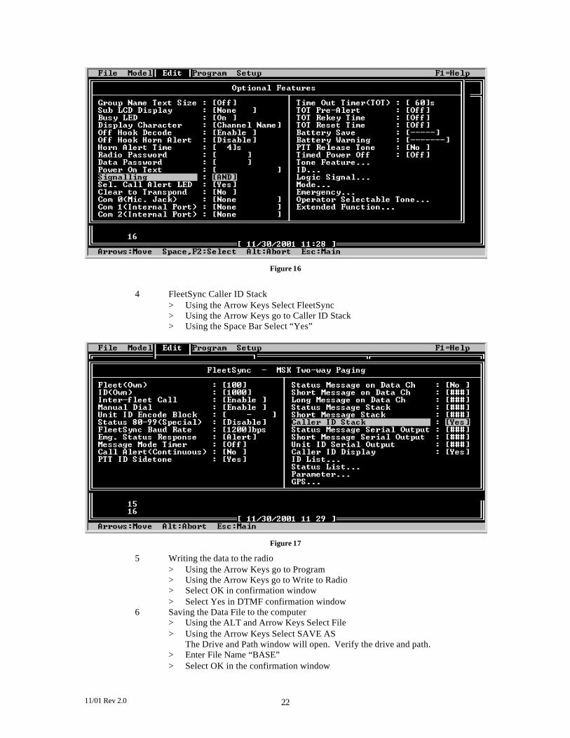
11/01 Rev 2.0 22
Figure 16
4 FleetSync Caller ID Stack
> Using the Arrow Keys Select FleetSync > Using the Arrow Keys go to Caller ID Stack > Using the Space Bar Select “Yes”
Figure 17
5 Writing the data to the radio > Using the Arrow Keys go to Program > Using the Arrow Keys go to Write to Radio > Select OK in confirmation window > Select Yes in DTMF confirmation window
6 Saving the Data File to the computer > Using the ALT and Arrow Keys Select File > Using the Arrow Keys Select SAVE AS
The Drive and Path window will open. Verify the drive and path. > Enter File Name “BASE” > Select OK in the confirmation window

11/01 Rev 2.0 23
Testing Selective Call Radio 1 Press the “A” button on the radio’s front panel. Using the “B” and “C” Keys select BASE, Press PTT
Base When the radio receives a Selective Call, it will display the radios Alias in the front panel. In addition to displaying the Alias, the receiving radio will store the Alias in one of the 3 Caller ID Stacks Indicated by IO1, IO2, IO3. Note: If Alias does not display and you see the 7 digit Fleet/ID number in the receiving radio, that alias has not been setup properly or is missing from the radio FleetSync/ID List.
¨ Programming FleetSync Status Messages The FleetSync status messages are quick short preprogrammed messages that can be passed from radio to radio with a series of button pushes. Status messaging is a basic feature in the 80 series radios and does not require the radio to be enhanced to display or send a status message. The 80 series radios can store and stack up to the last 9 status messages received. These are stored in volatile memory and will be lost if the radios power is turned off. Status numbers are assigned text (up to 16 characters) that when the radio receives a status number it will refer to its programming and display the text assigned to that status number. Status numbers range from 10 through 79, status numbers 80 through 88 are reserved for future use and status numbers 90 through 99 are reserved for controlling the radios Stun, Kill, Revive and Emergency functions. The status 89 in version 2 radios has been assigned to trigger the horn honk feature of the radio. The user may need to display a Status such as “Call Base” but not want the mobile unit to send “Call Base” back to the base unit. The 80 series Version 2 has an added feature shown below called TX inhibit. If in the mobile unit the status “Call Base” is set for TX inhibit then this will be a display only status and the mobile unit will not show this status in the users status message list.
Status Purpose 10-79 User assigned 80-87 Reserved 88 Emergency turn off 89 Horn Honk 90 Stun
( no tx ) 91 Stun
( no tx no rx) 92 Revive 93 Ack stun on 94 Ack stun off 95-97 Reserved 98 Mandown 99 Emergency
ID Base
ID * Radio 1

11/01 Rev 2.0 24
Exercise 8 Status Messaging Encode Programming Status Messaging (Radio1)
1 Load the radios data file we previously saved as Radio1 in Exercise 6 > Using the ALT and Arrow Keys Select File > Select Load Using the Arrow Keys > The Drive and Path window will open. Verify the drive and path. > Using the Arrow Keys Select the “Radio1” data file > Select OK in the confirmation window
2 Entering Messages in Status List > Using the ALT and Arrow Keys Select Edit > Using the Arrow Keys Select FleetSync > Using the Arrow Keys Select Status List > Enter 10 in Status field Note: Status messages are numbers from 10 – 79. Special status messages are numbered from 80 – 99 and are reserved for Emergency, Man Down, Horn Alert and other future features. > Enter “Return To Office” in Status Name Field
Note: 16 alphanumeric characters can be entered in the Status Name Field. Note: Status Inhibit prevents the user from selecting and transmitting the status message when using the “A” key.
> Enter 11 in Status field Note: Status messages are numbers from 10 – 79. Special status messages are numbered from 80 – 99 and are reserved for Emergency, Man Down, Horn Alert and other future features. > Enter “Arrived At Job” in Status Name Field
Note: 16 alphanumeric characters can be entered in the Status Name Field. > Press the ALT Key to return to FleetSync Window > Press the ALT Key to return to the Edit Menu
Figure 18
3 Writing the data to the radio > Using the Arrow Keys go to Program > Using the Arrow Keys go to Write to Radio > Select OK in confirmation window > Select Yes in DTMF confirmation window

11/01 Rev 2.0 25
4 Saving the Data File to the computer > Using the ALT and Arrow Keys Select File > Using the Arrow Keys Select SAVE AS
The Drive and Path window will open. Verify the drive and path. > Enter File Name “Radio1” > Select OK in the confirmation window
Exercise 9 Status Messaging Decode Programming Selective Calling Decode (Base)
1 Load the radios data file we previously saved as BASE in Exercise 7 > Using the ALT and Arrow Keys Select File > Select Load Using the Arrow Keys > The Drive and Path window will open. Verify the drive and path. > Using the Arrow Keys Select the “BASE” data file > Select OK in the confirmation window
2 Entering Messages in Status List > Using the ALT and Arrow Keys Select Edit > Using the Arrow Keys Select FleetSync > Using the Arrow Keys Select Status List > Enter 10 in Status field Note: Status messages are numbers from 10 – 79. Special status messages are numbered from 80 – 99 and are reserved for Emergency, Man Down, Horn Alert and other future features. > Enter “Return To Office” in Status Name Field
Note: 16 alphanumeric characters can be entered in the Status Name Field. Note: Status Inhibit prevents the user from selecting and transmitting the status message when using the “A” key.
> Enter 11 in Status field Note: Status messages are numbers from 10 – 79. Special status messages are numbered from 80 – 99 and are reserved for Emergency, Man Down, Horn Alert and other future features . > Enter “Arrived At Job” in Status Name Field
Note: 16 alphanumeric characters can be entered in the Status Name Field. > Press the ALT Key to return to FleetSync Window > Press the ALT Key to return to the Edit Menu

11/01 Rev 2.0 26
Figure 19
3 Writing the data to the radio > Using the Arrow Keys go to Program > Using the Arrow Keys go to Write to Radio > Select OK in confirmation window > Select Yes in DTMF confirmation window
4 Saving the Data File to the computer > Using the ALT and Arrow Keys Select File > Using the Arrow Keys Select SAVE AS
The Drive and Path window will open. Verify the drive and path. > Enter File Name “BASE” > Select OK in the confirmation window
Testing Status Message Radio 1 Press the “A” button on the radio’s front panel. Using the “B” and “C” Keys select BASE. Press the “A” button. Using the “B” and “C” Keys select a Status Message. Press PTT Base When the radio receives a Status Message, it will display the radios Alias in the front panel and the Status Message. In addition to displaying the Alias and Status, the receiving radio will store the Alias/Message in one of the 9 Status Message Stack. Note: If Alias does not display and you see the 7 digit Fleet/ID number in the receiving radio, that alias has not been setup properly or is missing from the radio FleetSync/ID List. If the receiving radio displays a 2 digit number instead of the status message, the alphanumeric message was not entered in the Status ID List.

11/01 Rev 2.0 27
¨ FleetSync Messages (Enhanced Required) FleetSync Protocol can be used to send two types of messages over the air, Long Messages and
Short Messages. FleetSync text messaging requires the radio be enhanced for both encode and decode. A long message may contain up to 1024 characters and is sent from a 80 series radio interfaced to a PC and received by a 80 series radio interfaced to a PC or other external device (KDS-100). A short message can contain up to 48 characters and will be displayed on the radios front panel. The 80 series can stack up to 4 short messages. These are stored in volatile memory and are lost when the radio’s power is turned off.
Minimum requirements are;
l Enhanced Option Installed l KCT-31 Interface Cable l Appropriate FleetSync CAD Software FleetSync Demo Software is available from Kenwood Tech Support
¨ FleetSync Short Message (Enhanced Required) A short Message is up to 48 characters max. The short message must originate from a 80 series interfaced to a PC but can be received and displayed on the front panel of the radio in the field. An 80 series radio can store and stack the 4 most recent short messages in the radio for retrieval later. Note: Status and Short Messages are stored in volatile memory and are lost when the radio is powered down . ¨ FleetSync Long Message ( Two PC’s Required ) A Long Message is up to 1024 characters max. A Long Message must originate and destinate to and from a PC or other external devise (KDS-100). A Long Message is NOT stored in the radio. A Long Message is always sent out the com port. ¨ Trouble Shooting the FleetSync Operation.
Most problems occur in the initial set up. The following is a list of trouble shooting tips to common problems. 1.The receiving radio doesn’t show the ID it receives.
a. Using FleetSync the radio has the ability to display the ID of the calling unit. Caller ID in the FleetSync Window of the KPG-49D must be enabled. PTT ID can be decoded and sent to an external display such as a PC or other external device. In order for the PTT ID to be sent to an external device the radio must be enhanced and the parameter “unit ID serial output” in the KPG-49D FleetSync Window must be enabled in the radios programming software.
2. The radios Com ports aren’t working. a. The PTT ID, status, short and long message features need to be enabled in the
KPG-49D FleetSync Window for Serial Output. b. The radio has not had the FleetSync Enhanced option enabled. c. The comports have not been enabled in the Optional Features section of the
radios programming software for data. 3. The radio hears all selective calls.
a. Check the AND/OR parameter in the Optional Features section of the radios programming software.
b. Set Optional Signaling for MSK

11/01 Rev 2.0 28
4. The base radio does not send GPS data to the PC.a. The type header word that is desired must be enable on both the mobile
and the base unit.b. The comport on the base must be set for DATA + GPS c. The initial NMEA data should not contain zero’s in the default data
stream. This can be the case when using NMEA O183 (HEADER $GPRMC). The GPS receiver should be configured to send both NMEA O183 and NMEA 0181 (HEADER $GPGGA).
5. The FleetSync decode is intermittent.a. TX data delay parameter in the FleetSync section of the radios programming
software is set low. The minimum recommended setting is 400 ms. This parameter can default to 0 if the radio was programmed with KPG49D version 1 software then read and reprogrammed with version 2 KPG49D software. It is recommended that a new file be created in KPG49D version and written to the radio.