542-08-#1 STATISTICS 542 Intro to Clinical Trials SURVIVAL ANALYSIS.

IPL, PC 18, 2006-17, 542 20 10-13
Spare Parts
Piezas de repuesto
Pièces de rechange
PC 18
Concrete Saw
542 20 10-13

542 19 10-12 - Large Target LogoLocation: Rear of Cowl
542 18 97-32 - Small Target LogoLocation: Blade Guard
542 18 76-91Location: Top of Cowl
539 30 14-89 - Depth IndicatorLocation: Top of Cowl
541 20 65-84 - TARGET / PC 18Location: Side of Cowl
(x2)
542 16 90-65 - Muffler WarningLocation: Engine Fuel Tank
539 30 14-72 - Main ControlLocation: Control Panel

Crank AssemblyDiagram C
Control Panel AssemblyDiagram D
Engine AssemblyDiagram H
Pointer AssemblyDiagram B
Belt Guard AssemblyDiagram G
Bladeshaft AssemblyDiagram I
Front Axle AssemblyDiagram F
Base Frame AssemblyDiagram A
Cowling AssemblyDiagram E
Blade Guard AssemblyDiagrams J & K
OptionalWater Tank Kit
(Not Shown Here)Diagram L
Reference Diagrams09.23.05

539 30 14-66
A725 25 05-76 (x2) 731 23 20-01 (x2)
541 20 65-56 (x2)
539 30 15-93 (x2)
541 20 65-55 (x4)
539 30 15-94
539 30 15-92 (x2)
728 84 45-01
Base Frame Assembly
728 84 45-01
728 84 45-01
Drill Point &Apply 242
Loctite
728 84 45-01
728 84 45-01
Apply 242Loctite
10.11.05
Drill Point &Apply 242
Loctite
Drill Point &Apply 242
Loctite
Drill Point &Apply 242
Loctite
728 84 45-01
Apply 242Loctite
539 30 00-81
541 20 65-53 (x2)
731 23 16-01 (x2)
725 23 72-71 (x2)
732 25 18-01 (x2)
Pointer Assembly
539 30 05-71
541 20 71-97
725 23 70-71
725 24 60-71 (x2)
725 23 72-71
731 23 16-01
541 20 61-63
732 25 16-01
04.25.06
541 20 71-84
B
A

Crank Assembly
539 30 14-67
732 25 22-01 (x4)
725 25 38-71 (x4)
541 20 65-58
541 20 65-59
725 25 34-71
734 11 78-01
542 20 57-87
728 84 45-01Apply 242
Loctite
539 30 14-50
Apply 242Loctite to
set screws
542 17 30-35
541 20 65-61
725 24 51-71
732 25 18-01
734 11 63-01539 30 07-59
539 30 05-54
539 30 14-49
539 30 14-48
04.26.06
C

Control Panel Assembly
539 30 14-72
539 30 14-89Black Wire
Green Wirew/ 6mm RingTerminal
724 12 24-01
539 30 05-62
539 30 05-61
539 30 08-22
539 30 14-89
732 25 16-01 (x2)
539 30 05-57 (x2)
725 23 72-71 (x2)
539 30 05-59
539 30 01-21
732 25 14-01 (x2)
724 12 93-01 (x2)
539 30 05-56
732 25 14-01
732 25 12-01 (x2)
539 30 01-22
539 30 01-19
724 13 27-01 (x2)
734 11 46-01 (x2)
539 30 14-72
541 20 69-21
539 30 05-74
539 30 05-55
734 11 46-01
539 30 01-21539 30 02-68
734 11 36-01 (x2)
734 11 52-01 (x2)
10.11.05
D
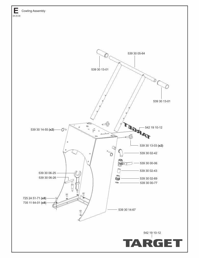
539 30 05-64
539 30 13-01
539 30 02-42
539 30 00-06
539 30 02-43
539 30 02-69
539 30 00-77
539 30 14-67
539 30 13-01
539 30 14-55 (x2)
539 30 06-25
539 30 06-26
725 24 51-71 (x8)
735 11 64-01 (x8)
542 19 10-12
542 19 10-12
539 30 13-03 (x2)
04.25.06
Cowling AssemblyE
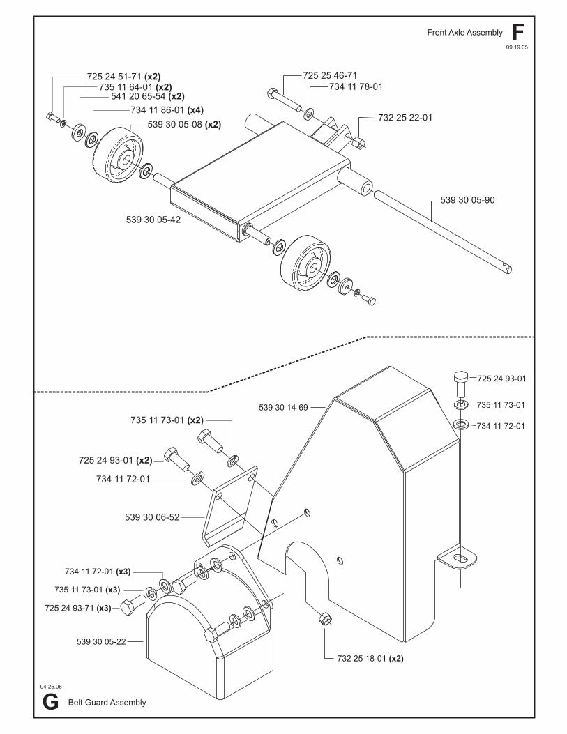
539 30 05-42
725 25 46-71
734 11 78-01
732 25 22-01
539 30 05-90
734 11 86-01 (x4)
541 20 65-54 (x2)735 11 64-01 (x2)
725 24 51-71 (x2)
539 30 14-69
725 24 93-01
735 11 73-01
732 25 18-01 (x2)
539 30 05-22
725 24 93-71 (x3)
735 11 73-01 (x3)
725 24 93-01 (x2)
734 11 72-01
539 30 06-52
539 30 05-08 (x2)
09.19.05
04.25.06
735 11 73-01 (x2)
734 11 72-01 (x3)
734 11 72-01
Front Axle Assembly
Belt Guard Assembly
F
G

728 84 45-01 (x2)
541 20 65-95
539 30 05-02
539 30 05-03
539 10 20-67
539 30 05-02
541 20 34-04
539 30 13-72
542 02 00-69
539 30 05-23
542 11 63-58 (x4)
539 30 05-26 (x2)
539 30 05-07 (x2)
539 30 05-00 (13hp)539 30 14-34 (9hp)
541 20 65-96
542 67 71-33
542 17 49-62 (x2)
542 16 90-65
728 84 45-01 (x2)
542 02 00-70
542 19 10-56 (x4)
Apply 242 Loctiteand Torque to100 Nm (74 Lb-Ft).
Apply 242Loctite to
Setscrews.
Drill point 539-30 00-23and 542 02 00-69 beforeinstalling 728 84 45-01.
Apply 242 Loctite.
Drill Point &Apply 242 Loctite
to Setscrews.
Engine Assembly
Bladeshaft Assembly
734 11 72-01 (x4)
732 25 20-01 (x4)
725 25 02-71 (x4)
734 11 72-01 (x4)
541 20 05-60 (x3)
542 16 90-65
542 16 93-66 (x3)
541 20 09-86
04.25.06
542 20 00-49542 16 73-04
542 16 73-06
542 16 76-22
542 18 33-75
541 20 70-31
Drill Point &Apply 242 Loctite
to Setscrews.
539 30 14-53 ( )LH
539 30 14-52 ( )RH
04.25.06
I
H

539 30 01-35 (5FT)
539 30 00-11
541 20 65-73
725 23 78-71 (x4)
542 13 90-45
725 23 31-71 (x2)
542 04 03-30
731 23 14-01 (x2)
542 13 90-51
735 11 73-01 (x2)
723 53 68-01 (x4)
542 04 92-12 (x2)
732 25 16-01 (x8)
542 02 08-64 (x2)
542 13 90-98
734 11 46-01 (x2)
725 25 13-51
735 11 73-01
725 24 93-71 (x2)
542 19 51-89 (x2)
725 24 53-71 (x2)
732 25 18-01
542 19 51-27
725 24 53-71 (x3)
542 19 51-20
541 20 65-71
734 11 63-01 (x2)
725 24 53-71
732 25 18-01 (x2)
734 11 63-01 (x3)
Blade Guard Assembly - 18”
Blade Guard Assembly - 18”
732 25 18-01 (x3)
732 25 16-01 (x6)
732 25 14-01 (x2)
725 23 31-71 (x2)
04.25.06
04.25.06
542 18 97-32
541 20 70-26 Blade Guard, Blue - Compl
J
K

541 20 17-17
541 20 13-58
539 30 05-80
725 24 53-71 (x4)
539 30 13-59
539 30 09-19 (x2)
732 25 16-01 (x4)
539 30 05-48
725 23 68-71 (x4)
539 30 09-20
541 20 46-74
541 20 07-07
539 30 14-09
539 30 14-10
735 11 64-01 (x4)
734 11 63-01 (x4)
539 30 13-58 (x2)
After market water tank installation requirestwo holes for the water tubes to be drilled inblade guard as shown above.
3/8” (9.5mm) both sides
4 3/4” (121mm)13 ½”(343mm)
04.25.06
Water Tank Kit: Optional541 20 04-30 Kit - Compl
541 20 07-07 (x2)
L

PC 18PART NO. POS. DESCRIPTION PART NO. POS. DESCRIPTION
539 30 00-06 E BALL VALVE, 1/2 541 20 61-63 B POINTER WELDMENT, BLACK539 30 00-11 J HOSE CLAMP, MAH-6 5/16-7/8 541 20 65-53 B COLLAR539 30 00-77 E WASHER HOSE 541 20 65-54 F FRONT WHEEL CAP539 30 00-81 B WHEEL 541 20 65-55 A REAR WHEEL WASHER539 30 01-19 D SPRING, EXTENSION 541 20 65-56 A REAR WHEEL SLEEVE539 30 01-21 D 1/8" CABLE CLAMP 541 20 65-58 C KEY, 6 SQ X 20 LG539 30 01-22 D WIRE ROPE CABLE 541 20 65-59 C SPACER, HAND WHEEL539 30 01-35 J HOSE, WATER 1/2" (5 FT) 541 20 65-61 C SPACER539 30 02-42 E PIPE FITTING, STREET EL, 1/2 GALV 541 20 65-71 K BLADE GUARD WELD, REAR 18" BLUE539 30 02-43 E PIPE FITTING, CLOSE NIPPLE 1/2 GALV 541 20 65-73 J FITTING, HOSE 3/8"NPT - 1/2"BARB
539 30 02-68 D 1/8" COTTER PIN 541 20 65-76 G BELT PROTECTOR BLUE 539 30 02-69 E HOSE COUPLING 541 20 65-84 Decal DECAL, TARGET - PC18539 30 05-00 H ENGINE, HONDA 13HP 541 20 65-95 I PULLEY, 3VX3GR4.12 X 30 W/SS539 30 05-02 I INNER COLLAR 541 20 65-96 H PULLEY, 3VX3GR3.00 X 1.00 W/SS539 30 05-03 I OUTER COLLAR ASSY 541 20 69-21 D EMERGENCY STOP SWITCH539 30 05-07 I BEARING, TAP BASE 30mm 541 20 70-26 J BLADE GU ARD, BLUE 18" - Compl539 30 05-08 F FRONT WHEEL 541 20 70-34 H O-SEALING RING, M9539 30 05-22 G SHAFT GUARD 541 20 71-84 B GUARD, RUBBER POINTER539 30 05-23 I BLADESHAFT, 30mm 541 20 71-97 B BUMPER, RECESS STYLE539 30 05-26 I BLADESHAFT SPACER 541 20 72-82 B KIT, BUMPER CONVERSION
539 30 05-42 F FRONT AXLE WELDMENT 542 02 00-49* H HOSE CLAMP WORM DRIVE539 30 05-48 L WATER TANK TRAY BLACK 542 02 00-69* I KEY, .25 SQ X 2.00539 30 05-54 C GREASE ZERK, M6 X 1.0 45 DEG 542 02 00-70* H KEY, .25 SQ X 2.125539 30 05-55 D THROTTLE CONTROL ASSY 542 02 08-64* J PLUG, 1/8 NPT539 30 05-56 D TACH/HOURMETER 542 04 03-30* J SPRING, 054 WIRE X .375 OD539 30 05-57 D PULLEY 542 04 92-12* J CLAMP, WATER TUBE539 30 05-59 D PULLEY 542 13 90-45* J WATER MANIFOLD539 30 05-61 D SNAP RING, M8 542 13 90-51* J GASKET, WATER MANIFOLD539 30 05-62 D DEPTH INDICATOR KNOB 542 13 90-98* J FLAP SPLASH539 30 05-64 E HANDLE BAR WELDMENT 542 16 63-58* I WASHER, LOCK M14
539 30 05-71 B POINTER ROD 542 16 71-33* H ADAPTER, M12X 10 HOSE BARB539 30 05-74 D DEPTH INDICATOR PIN 542 16 73-04* H HOSE ASSY, OUIL DRAIN539 30 05-80 L WATER TANK 5.5 GAL 542 16 73-06* H CAP, OIL DRAIN539 30 05-90 F FRONT AXLE PIN 542 16 76-22* H NUT, TUBE M16539 30 06-25 E WRENCH, BLADESHAFT NUT 542 16 90-65* H DECAL, CAUTION MUFFLER HOT539 30 06-26 E LOCK PIN, BLADESHAFT 542 16 93-66* H SCREW, SELF-TAP #8 X 3/8" TYPE "B"539 30 07-59 C DETENT CLIP 542 17 30-35* C WASHER, FLAT M20 DIN 125539 30 08-22 D BUSHING 542 17 49-62* H SPACER PLATE539 30 09-19 L TIE DOWN BRKT 542 18 33-75* H PLUG, HOLE539 30 09-20 L WATER FLOW VALVE 542 18 76-91* Decal DECAL, TARGETBLUE.COM
539 30 13-01 E HAND GRIP 542 18 97-32* Decal DECAL, TARGET - SMALL539 30 13-03 E HANDLE BAR KNOB 542 19 10-12* Decal,E DECAL, TARGET - LARGE539 30 13-58 L SPRAY NOZZLE 542 19 10-56* I BOLT, M14 X 2.0 X 55 8.8 Z/P539 30 13-59 L TIE DOWN CORD 542 19 51-20* K BLADE GUARD WELD, FRONT 18" BLUE539 30 13-72 I THREAD PROTECTOR 542 19 51-27* K HINGE, 3"539 30 14-09 L QUICK DISCONNECT 1/4 BARB 542 19 51-89* J TUBE, WATER 18"539 30 14-10 L QUICK DISCONNECT 1/4 NPT 542 20 51-87 C HAND WHEEL539 30 14-34 H ENGINE, HONDA 9HP539 30 14-48 C CRANK ROD539 30 14-49 C SCREW TUBE WELDMENT
539 30 14-50 C CRANK BEARING539 30 14-52 I NUT, M24 X 3.00 8.8 R.H.539 30 14-53 I NUT, M24 X 3.00 8.8 L.H.539 30 14-55 E LOCK PIN539 30 14-66 A BASE FRAME WELDMENT BLUE539 30 14-67 B,E COWLING WELDMENT BLUE539 30 14-72 D DECAL, MAIN CONTROL539 30 14-72 D DECAL, MAIN CONTROL539 30 14-89 D DECAL, DEPTH INDICATOR539 30 15-92 A REAR WHEEL
539 30 15-93 A SET COLLAR539 30 15-94 A REAR AXLE PIN541 20 04-30 L WATER TANK KIT541 20 05-60 H BELT, 3VX300541 20 07-07 L WATER TUBE, CLEAR 1/4" ID (3FT)541 20 09-86 H DEFLECTOR, MUFFLER541 20 13-58 L CAP, WATER TANK541 20 17-17 L DECAL, WATER ONLY541 20 34-04 I KEY, 1/4 SQ X 3/4541 20 46-74 L PLASTIC "Y" FITTING, 1/2"
NOTE: Part No's. that have an ASTERISK (*) suffix may not be active 9-digit numbers. The '542' prefix has been added to current 6-digit part numbers and '0' to 7 and 8-digit numbers. 04.26.06

PC 18PART NO. POS. DESCRIPTION PART NO. POS. DESCRIPTION
723 53 68-01 J SCREW, FLT HD M6 x 1.0 x 16 (167818)724 12 24-01 D SCREW, PAN HD M3 x 0.5 x 10724 12 93-01 D SCREW, PAN HD M4 x 0.7 x 16724 13 27-01 D SCREW, PAN HD M5 x 0.8 x 12725 23 31-71 J BOLT, M5 x 0.8 x 20 (167761)725 23 68-71 L BOLT, M6 x 1.0 x 16 8.8725 23 70-71 B BOLT, M6 x 1.0 x 20 10.9 DIN933725 23 72-71 B,D BOLT, M6 x 1.0 x 25 8.8 FT725 23 78-71 J BOLT, M6 x 1.0 x 40 8.8 FT725 24 51-71 E,F BOLT, M8 x 1.25 x 20
725 24 53-71 K,L BOLT, M8 x 1.25 x 25 8.8725 24 60-71 B BOLT, M8 x 1.25 x 45 725 24 93-71 G,J BOLT, M10 x 1.5 x 25 8.8725 25 02-71 H BOLT, M10 x 1.5 x 55 8.8725 25 05-76 A BOLT, M10 x 1.5 x 70 8.8725 25 13-51 J BOLT, M10 x 1.5 x 110 8.8725 25 34-71 C BOLT, M12 x 1.75 x 25 8.8725 25 38-71 C BOLT, M12 x 1.75 x 35 8.8725 25 46-71 F BOLT, M12 x 1.75 x 70 8.8 FT728 84 45-01 A,C,H,I SET SCREW, CUP PT M8 x 1.25 x10
731 23 14-01 J NUT, M5 x 0.8 8.8731 23 16-01 B NUT, M6 x 1.0 8.8731 23 20-01 A NUT, M10 x 1.5 8.8732 25 12-01 D NUT, M4 x 0.7 8.8 NYLOC732 25 14-01 D,J NUT, M5 x 0.8 8.8 NYLOC732 25 16-01 B NUT, M6 x 1.0 8.8 NYLOC732 25 16-01 B,D,J,L NUT, M6 x 1.0 FIBER732 25 18-01 B,C,G,K NUT, M8 x 1.25 8.8 NYLOC732 25 20-01 H NUT, M10 x 1.5 8.8 NYLOC732 25 22-01 C,F NUT, M12 x 1.75 8.8 NYLOC
734 11 36-01 D WASHER, FLAT M4 Z/P734 11 46-01 D,J WASHER, FLAT M5 Z/P734 11 63-01 K,L WASHER, FLAT M8 Z/P734 11 72-01 G,H WASHER, FLAT M10 Z/P734 11 78-01 C,F WASHER, FLAT M12 Z/P734 11 86-01 F WASHER, FLAT M16 Z/P735 11 64-01 E,F,L WASHER, LOCK M8 Z/P735 11 73-01 G,J WASHER, LOCK M10 Z/P
NOTE: Part No's. that have an ASTERISK (*) suffix may not be active 9-digit numbers. The '542' prefix has been added to current 6-digit part numbers and '0' to 7 and 8-digit numbers. 04.26.06

Target Corporate Office17400 West 119th StreetOlathe, Kansas 66061
Customer Service: 800-288-5040Customer Serv. Fax: 800-825-0028
Corporate Office: 913-928-1000Corp. Office Fax: 913-438-7951
Target InternationalCustomer Service: 913-928-1300
Customer Serv. Fax: 913-438-7938
Target CanadaCustomer Service: 800-461-9589
Customer Serv. Fax: 800-728-1907
www.targetblue.com
Printed in the USA
DUST WARNING
Cutting, especially when DRY cutting, generates dust that comes from the material being cut,which frequently contains silica. Silica is a basic component of sand, quartz, brick clay, granite andnumerous other minerals and rocks. Exposure to excessive amount of such dust can cause:
Respiratory diseases (affecting your ability to breath), including chronic bronchitis, silicosisand pulmonary fibrosis from exposure to silica. These diseases may be fatal;
Skin irritation and rash; and
Cancer according to NTP* and IARC*National* Toxicology Program / International Agency for Research on Cancer
Take precautionary steps
Avoid inhalation of and skin contact with dust, mist and fumes;
Wet cut when feasible, to minimize dust;
Wear and ensure that all bystanders wear appropriate respiratory protection such as dustmasks designed to filter out microscopic particles. (See OSHA 29 CFR Part 1910.1200)
California Prop 65 Warning:Use of this product can cause exposure to materials known to the State of California to cause cancer
and/or birth defects or other reproductive harm.