
PARTS LINCOLN RANGER 305D.pdf
22
RANGER ® 305D (CE) P-479 P-479 PARTS LIST FOR RANGER ® 305D (CE) Kubota Engine RETURN TO MAIN INDEX Index of Sub Assemblies Index of Sub Assemblies Index of Sub Assemblies Index of Sub Assemblies Illustration of Sub Assemblies Illustration of Sub Assemblies Illustration of Sub Assemblies Illustration of Sub Assemblies
-
Upload
mekanicobucaro -
Category
Documents
-
view
1.348 -
download
82
Transcript of PARTS LINCOLN RANGER 305D.pdf
RANGER® 305D (CE)
P-479P-479
PARTS LIST FOR
RANGER® 305D (CE)Kubota Engine
RETURN TO MAIN INDEX
Ind
exo
fS
ubA
ssem
blie
sIn
dex
of
Sub
Ass
emb
lies
Ind
exo
fS
ubA
ssem
blie
sIn
dex
of
Sub
Ass
emb
lies
Illus
trat
ion
of
Sub
Ass
emb
lies
Illus
trat
ion
of
Sub
Ass
emb
lies
Illus
trat
ion
of
Sub
Ass
emb
lies
Illus
trat
ion
of
Sub
Ass
emb
lies

RANGER® 305D (CE) 08-03-2009
P-479-AP-479-A
ILLUSTRATION OF SUB-ASSEMBLIES
Ind
exo
fS
ubA
ssem
blie
sIn
dex
of
Sub
Ass
emb
lies
Ind
exo
fS
ubA
ssem
blie
sIn
dex
of
Sub
Ass
emb
lies
HIGHIDLE
AUTOIDLE
D
7
6
3
4
2
15
RANGER® 305D (CE) 04-08-2010
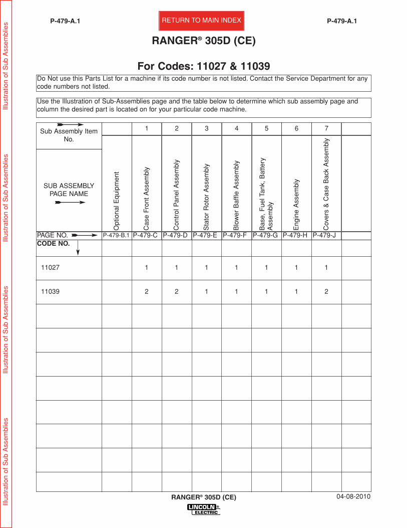
Do Not use this Parts List for a machine if its code number is not listed. Contact the Service Department for anycode numbers not listed.
Use the Illustration of Sub-Assemblies page and the table below to determine which sub assembly page andcolumn the desired part is located on for your particular code machine.
P-479-A.1P-479-A.1
RANGER® 305D (CE)
For Codes: 11027 & 11039
CODE NO.
11027 1 1 1 1 1 1 1
11039 2 2 1 1 1 1 2
Cov
ers
& C
ase
Bac
k A
ssem
bly
P-479-J
7
Eng
ine
Ass
embl
y
P-479-H
6
Bas
e, F
uel T
ank,
Bat
tery
Ass
embl
y
P-479-G
5
Blo
wer
Baf
fle A
ssem
bly
P-479-F
4
Sta
tor
Rot
or A
ssem
bly
P-479-E
3
Con
trol
Pan
el A
ssem
bly
P-479-D
2
Cas
e Fr
ont
Ass
embl
y
P-479-C
1
Opt
iona
l Equ
ipm
ent
P-479-B.1
SUB ASSEMBLYPAGE NAME
PAGE NO.
Sub Assembly ItemNo.
Illus
trat
ion
of S
ub A
ssem
blie
sIll
ustr
atio
n of
Sub
Ass
embl
ies
Illus
trat
ion
of S
ub A
ssem
blie
sIll
ustr
atio
n of
Sub
Ass
embl
ies RETURN TO MAIN INDEX

RANGER® 305D (CE)
DESCRIPTION . . . . . . . . . . . . . . . . . . . . . . . . . . . . . . . . . . . . . . . . . . . . . . . . . . . . . . . . . . . . . . . . . . . . . . .PART NUMBER
Accessory Package . . . . . . . . . . . . . . . . . . . . . . . . . . . . . . . . . . . . . . . . . . . . . . . . . . .Order K704Spark Arrestor . . . . . . . . . . . . . . . . . . . . . . . . . . . . . . . . . . . . . . . . . . . . . . . . . . . . . . .Order K1898-1Remote Output Control (7.6m) . . . . . . . . . . . . . . . . . . . . . . . . . . . . . . . . . . . . . . . . . .Order K857Remote Output Control (30.5m) . . . . . . . . . . . . . . . . . . . . . . . . . . . . . . . . . . . . . . . . .Order K857-1
08-03-2009
Miscellaneous Options Available for your machine are listed below:# Indicates a change this printing.
P-479-B.1P-479-B.1 OPTIONAL EQUIPMENT LISTING
Ind
exo
fS
ubA
ssem
blie
sIn
dex
of
Sub
Ass
emb
lies
Ind
exo
fS
ubA
ssem
blie
sIn
dex
of
Sub
Ass
emb
lies

RANGER® 305D (CE)
NOTES
Ind
exo
fS
ubA
ssem
blie
sIn
dex
of
Sub
Ass
emb
lies
Ind
exo
fS
ubA
ssem
blie
sIn
dex
of
Sub
Ass
emb
lies

RANGER® 305D (CE) 04-08-2010
P-479-CP-479-C
Case Front Assembly
Inde
x of
Sub
Ass
embl
ies
Inde
x of
Sub
Ass
embl
ies
Inde
x of
Sub
Ass
embl
ies
Inde
x of
Sub
Ass
embl
ies
Par
t N
umbe
rsP
art
Num
bers
Par
t N
umbe
rsP
art
Num
bers
3A3A3B3B
6
4
7
8 1212
11111414
2828
15A15A
2A2A
3131
32B32B
1010 9
2929
16A16A
18A18A
18B18B
20B20B
5
1
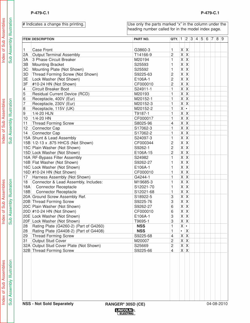
1 Case Front G3860-3 1 X X2A Output Terminal Assembly T14166-9 2 X X3A 3 Phase Circuit Breaker M20194 1 X X3B Mounting Bracket S25593 1 X X3C Mounting Plate (Not Shown) S25592 1 X X3D Thread Forming Screw (Not Shown) S9225-63 2 X X3E Lock Washer (Not Shown) E106A-1 2 X X3F #10-24 HN (Not Shown) CF000010 2 X X4 Circuit Breaker Boot S24911-1 1 X X5 Residual Current Device (RCD) M20193 1 X X6 Receptacle, 400V (Eur) M20152-1 1 X X7 Receptacle, 230V (Eur) M20152-3 1 X X8 Receptacle, 115V (UK) M20152-2 1 X •9 1/4-20 HLN T9187-1 1 X X10 1/4-20 HN CF000017 1 X X11 Thread Forming Screw S8025-96 4 X X12 Connector Cap S17062-3 1 X X14 Connector Cap S17062-2 1 X X15A Shunt & Lead Assembly S24097-3 1 X X15B 1/2-13 x .875 HHCS (Not Shown) CF000344 2 X X15C Plain Washer (Not Shown) S9262-1 2 X X15D Lock Washer (Not Shown) E106A-15 2 X X16A RF-Bypass Filter Assembly S24982 1 X X16B Flat Washer (Not Shown) S9262-27 1 X X16C Lock Washer (Not Shown) E106A-1 1 X X16D #10-24 HN (Not Shown) CF000010 1 X X17 Harness Assembly (Not Shown) G4244-1 1 X X18 Connector & Lead Assembly, Includes: M19685-3 1 X X18A Connector Receptacle S12021-70 1 X X18B Connector Receptacle S12021-68 1 X X20A Ground Screw Assembly Ref. S18922-5 3 X X20B Thread Forming Screw S9225-76 3 X X20C Plain Washer (Not Shown) S9262-27 6 X X20D #10-24 HN (Not Shown) CF000010 6 X X20E Lock Washer (Not Shown) E106A-1 3 X X20F Lock Washer (Not Shown) T9695-1 3 X X28 Rating Plate (G4260-2) (Part of G4260) NSS 1 X •28 Rating Plate (G4408-2) (Part of G4408) NSS 1 • X29 Thread Forming Screw S9225-68 4 X X31 Output Stud Cover M20007 2 X X32A Output Stud Cover Plate (Not Shown) S25669 2 X X32B Thread Forming Screw S9225-66 4 X X
04-08-2010RANGER® 305D (CE)
Use only the parts marked “x” in the column under theheading number called for in the model index page.
# Indicates a change this printing.
P-479-C.1
ITEM DESCRIPTION PART NO. QTY. 1 2 3 4 5 6 7 8 9
P-479-C.1
Inde
x of
Sub
Ass
embl
ies
Inde
x of
Sub
Ass
embl
ies
Inde
x of
Sub
Ass
embl
ies
Inde
x of
Sub
Ass
embl
ies
Sub
Ass
embl
y Ill
ustr
atio
nS
ub A
ssem
bly
Illus
trat
ion
Sub
Ass
embl
y Ill
ustr
atio
nS
ub A
ssem
bly
Illus
trat
ion
NSS - Not Sold Separately
RANGER® 305D (CE) 04-08-2010
P-479-DP-479-D
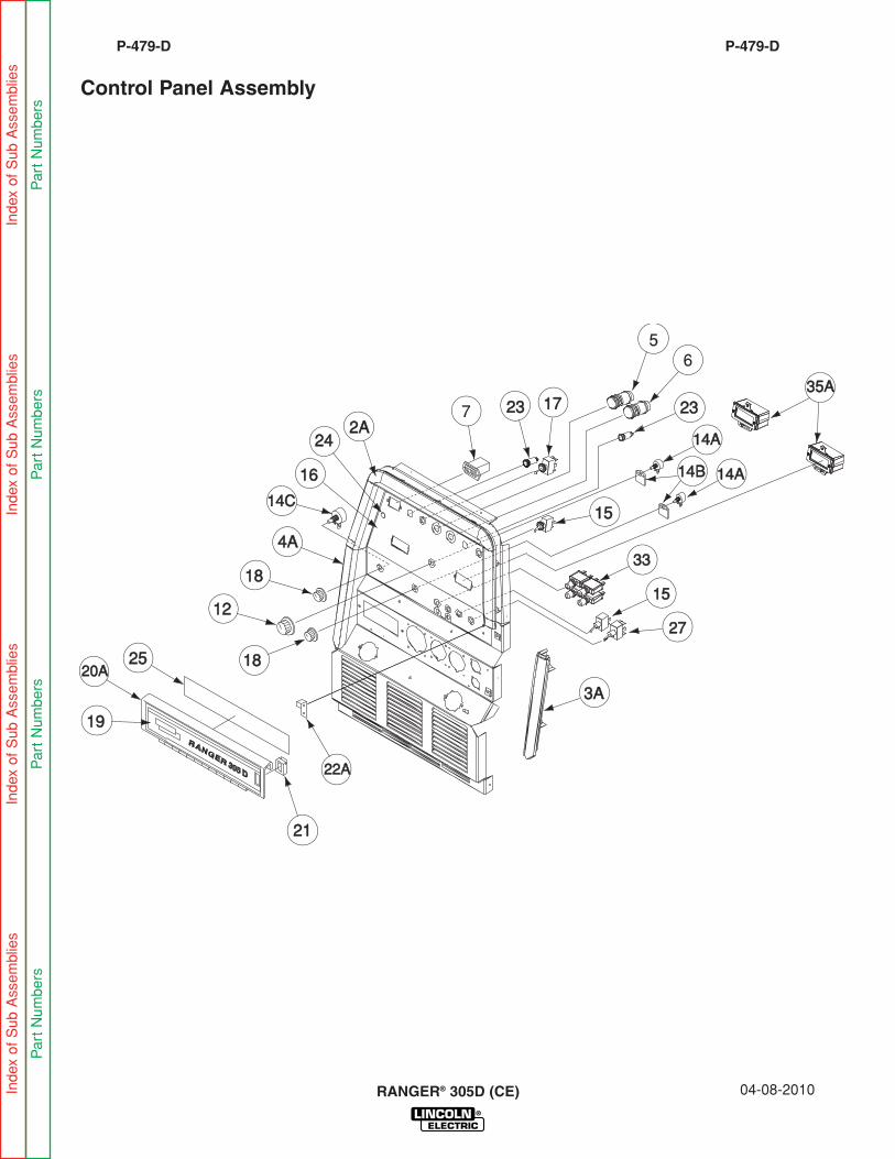
Control Panel Assembly
Inde
x of
Sub
Ass
embl
ies
Inde
x of
Sub
Ass
embl
ies
Inde
x of
Sub
Ass
embl
ies
Inde
x of
Sub
Ass
embl
ies
Par
t N
umbe
rsP
art
Num
bers
Par
t N
umbe
rsP
art
Num
bers
1919
2A2A
4A4A
1616
22A22A
1212
2424
1818
1818
17172323 2323
1515
56
14C14C
14B14B
2727
1515
3333
14A14A
14A14A
3A3A
252520A20A
2121
7
35A35A

2A Top Bezel G3593 1 X X2B Self Tapping Screw (Not Shown) S24738-1 4 X X3A Right Bezel G3594-1 1 X X3B Self Tapping Screw (Not Shown) S24738-1 2 X X4A Left Bezel G3594-2 1 X X4B Self Tapping Screw (Not Shown) S24738-1 2 X X5 Switch, Push-Button S13146-4 1 X X6 Start Button S13146-1 1 X X7 Hour Meter-Miniature S17475-3 1 X X12 Knob T10491-1 1 X X13 “O” Ring (Not Shown) T13483-7 3 X X
Connector & Lead Assembly, (Includes): M19685-4 1 X X14A Potentiometer (10K) T10812-112 2 X X14B Potentiometer Spacer S18280 2 X X14C Rotary Switch S16670-10 1 X X15 Switch, Toggle,SPST T10800-38 2 X X16 Nameplate - 50Hz/UK (G4260-1) (Part of G4260) NSS 1 X •16 Nameplate - 50Hz/Europe (G4408-1) (Part of G4408) NSS 1 • X17 Switch, Toggle, DPDT T10800-36 1 X X18 Knob T10491 2 X X19 Front Door Nameplate L11746-2 1 X X20A Door Welded Assembly L11185 1 X X20B Rivet (Not Shown) T12584-6 2 X X21 Latch S21033 1 X X22A Catch Bracket S24659 1 X X22B Self Tapping Screw (Not Shown) S8025-98 2 X X23 Pilot Light T13534-11 2 X X24 Fastener Button T14659-1 2 X X25 Engine Service Decal (L12037-3) (Part of L12037) NSS 1 X X27 Toggle Switch T10800-39 1 X X33 Circuit Breaker T12287-22 4 X X34 Sealing Boot (Not Shown) S22061-1 4 X X35 Digital Weld Meter Kit, Includes: (35A thru 35E) K2467-1 1 X X35A Meter Housing Assembly (L11160) NSS 2 X X35B Meter Housing Seal (Not Shown) S24630 2 X X35C Meter Bezel (Not Shown) M19368 2 X X35D Lens (Not Shown) T14807-9 2 X X35E #4-40 x .375 SS-PPNHS (Not Shown) CF000389 4 X X35F #6-32 HN (Not Shown) CF000005 4 X X35G Plain Washer (Not Shown) S9262-3 4 X X
04-08-2010RANGER® 305D (CE)
Use only the parts marked “x” in the column under theheading number called for in the model index page.
# Indicates a change this printing.
P-479-D.1
ITEM DESCRIPTION PART NO. QTY. 1 2 3 4 5 6 7 8 9
P-479-D.1
Inde
x of
Sub
Ass
embl
ies
Inde
x of
Sub
Ass
embl
ies
Inde
x of
Sub
Ass
embl
ies
Inde
x of
Sub
Ass
embl
ies
Sub
Ass
embl
y Ill
ustr
atio
nS
ub A
ssem
bly
Illus
trat
ion
Sub
Ass
embl
y Ill
ustr
atio
nS
ub A
ssem
bly
Illus
trat
ion
NSS - Not Sold Separately
##
RANGER® 305D (CE) 08-03-2009
P-479-EP-479-E
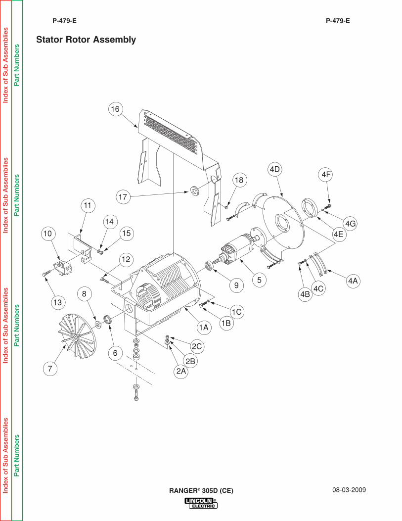
Stator Rotor Assembly
Ind
exo
fS
ubA
ssem
blie
sIn
dex
of
Sub
Ass
emb
lies
Ind
exo
fS
ubA
ssem
blie
sIn
dex
of
Sub
Ass
emb
lies
Par
tN
umb
ers
Par
tN
umb
ers
Par
tN
umb
ers
Par
tN
umb
ers
16
17
184D
4F
4E4G
4A4C
4B9
5
1C1B
2A2B
1A
2C
7
6
813
12
15
14
11
10
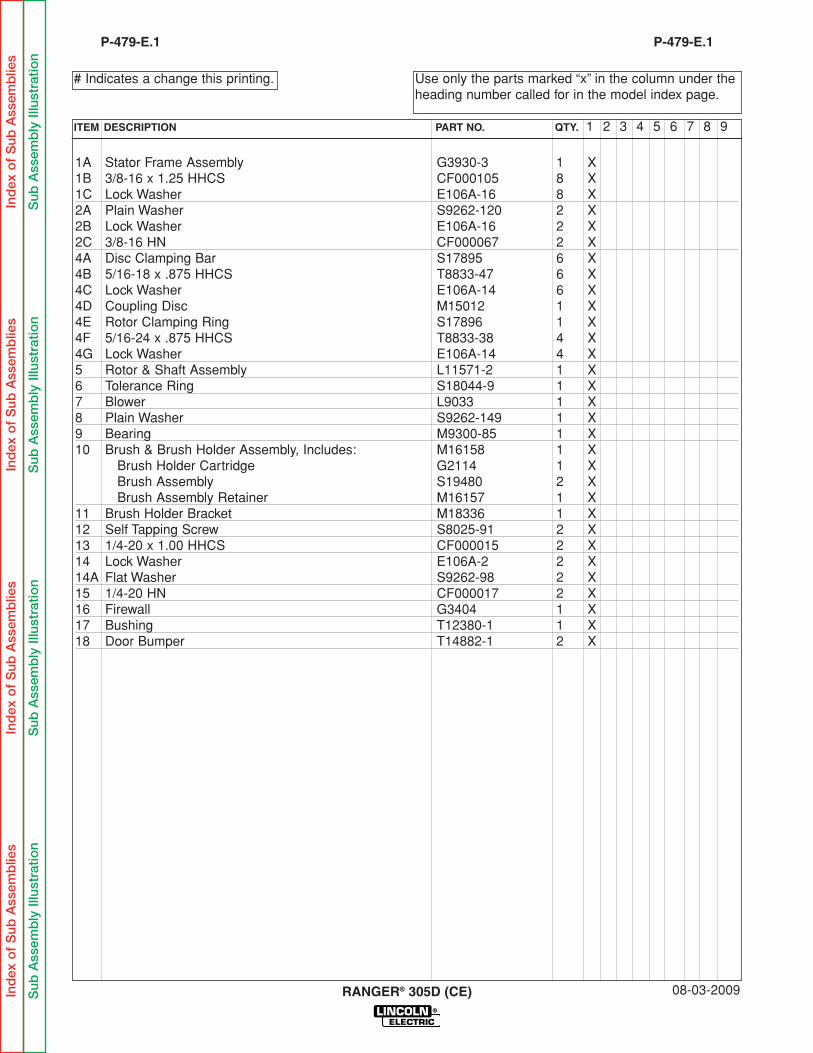
1A Stator Frame Assembly G3930-3 1 X1B 3/8-16 x 1.25 HHCS CF000105 8 X1C Lock Washer E106A-16 8 X2A Plain Washer S9262-120 2 X2B Lock Washer E106A-16 2 X2C 3/8-16 HN CF000067 2 X4A Disc Clamping Bar S17895 6 X4B 5/16-18 x .875 HHCS T8833-47 6 X4C Lock Washer E106A-14 6 X4D Coupling Disc M15012 1 X4E Rotor Clamping Ring S17896 1 X4F 5/16-24 x .875 HHCS T8833-38 4 X4G Lock Washer E106A-14 4 X5 Rotor & Shaft Assembly L11571-2 1 X6 Tolerance Ring S18044-9 1 X7 Blower L9033 1 X8 Plain Washer S9262-149 1 X9 Bearing M9300-85 1 X10 Brush & Brush Holder Assembly, Includes: M16158 1 X
Brush Holder Cartridge G2114 1 XBrush Assembly S19480 2 XBrush Assembly Retainer M16157 1 X
11 Brush Holder Bracket M18336 1 X12 Self Tapping Screw S8025-91 2 X13 1/4-20 x 1.00 HHCS CF000015 2 X14 Lock Washer E106A-2 2 X14A Flat Washer S9262-98 2 X15 1/4-20 HN CF000017 2 X16 Firewall G3404 1 X17 Bushing T12380-1 1 X18 Door Bumper T14882-1 2 X
08-03-2009RANGER® 305D (CE)
Use only the parts marked “x” in the column under theheading number called for in the model index page.
# Indicates a change this printing.
P-479-E.1
ITEM DESCRIPTION PART NO. QTY. 1 2 3 4 5 6 7 8 9
P-479-E.1
Ind
exo
fS
ubA
ssem
blie
sIn
dex
of
Sub
Ass
emb
lies
Ind
exo
fS
ubA
ssem
blie
sIn
dex
of
Sub
Ass
emb
lies
Sub
Ass
emb
lyIll
ustr
atio
nS
ubA
ssem
bly
Illus
trat
ion
Sub
Ass
emb
lyIll
ustr
atio
nS
ubA
ssem
bly
Illus
trat
ion
RANGER® 305D (CE) 08-03-2009
P-479-FP-479-F
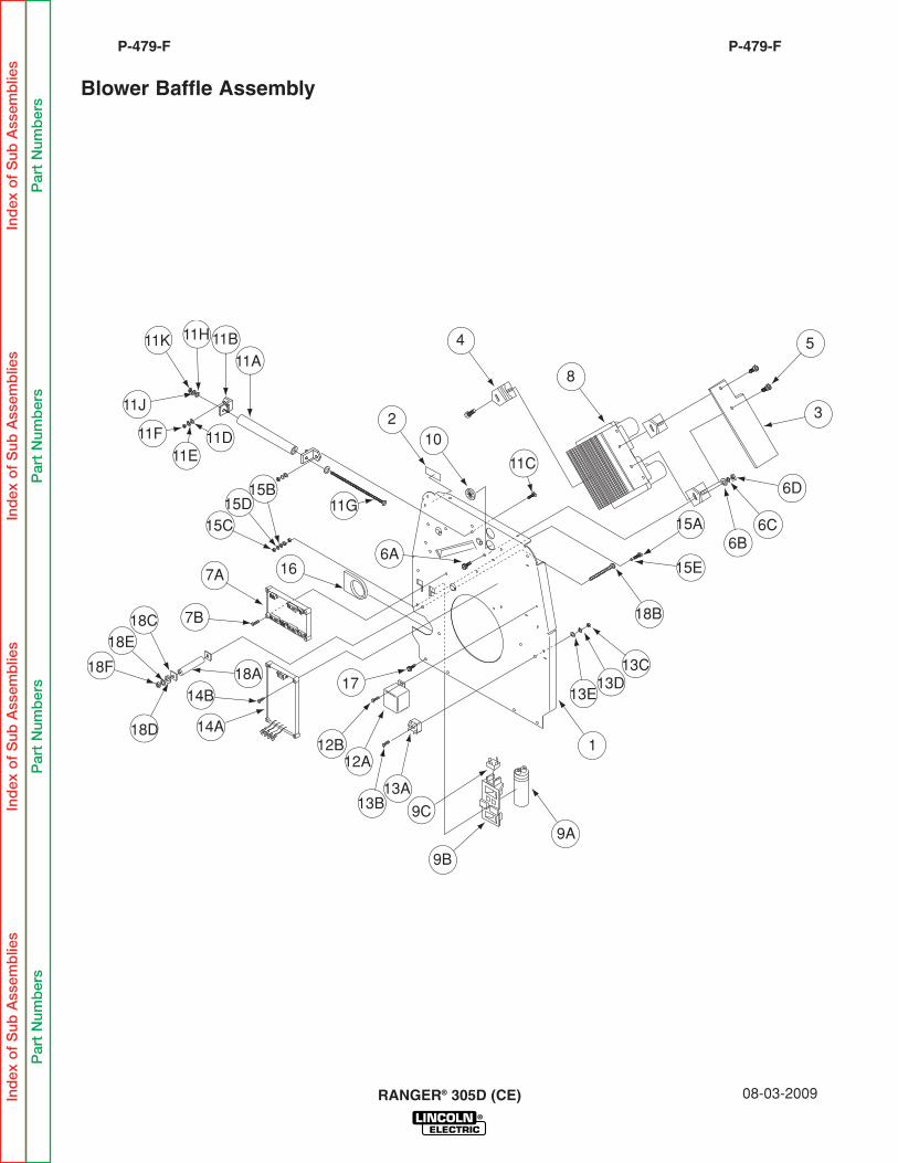
Blower Baffle Assembly
Ind
exo
fS
ubA
ssem
blie
sIn
dex
of
Sub
Ass
emb
lies
Ind
exo
fS
ubA
ssem
blie
sIn
dex
of
Sub
Ass
emb
lies
Par
tN
umb
ers
Par
tN
umb
ers
Par
tN
umb
ers
Par
tN
umb
ers
4
8
5
3
6D
6B6C
102
6A16
17
7A
18C18E
18F
15C
14A
14B
9C
9B
18A
18B
13E13D
13C
1
9A
15D15A
15E
11A11B11H11K
11J
11F11E
11D
11G
11C
15B
13A13B
12A12B
7B
18D
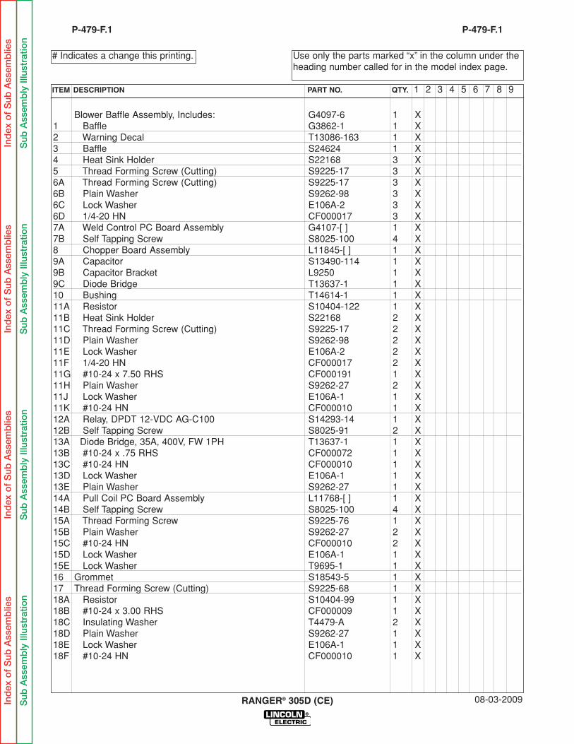
Blower Baffle Assembly, Includes: G4097-6 1 X1 Baffle G3862-1 1 X2 Warning Decal T13086-163 1 X3 Baffle S24624 1 X4 Heat Sink Holder S22168 3 X5 Thread Forming Screw (Cutting) S9225-17 3 X6A Thread Forming Screw (Cutting) S9225-17 3 X6B Plain Washer S9262-98 3 X6C Lock Washer E106A-2 3 X6D 1/4-20 HN CF000017 3 X7A Weld Control PC Board Assembly G4107-[ ] 1 X7B Self Tapping Screw S8025-100 4 X8 Chopper Board Assembly L11845-[ ] 1 X9A Capacitor S13490-114 1 X9B Capacitor Bracket L9250 1 X9C Diode Bridge T13637-1 1 X10 Bushing T14614-1 1 X11A Resistor S10404-122 1 X11B Heat Sink Holder S22168 2 X11C Thread Forming Screw (Cutting) S9225-17 2 X11D Plain Washer S9262-98 2 X11E Lock Washer E106A-2 2 X11F 1/4-20 HN CF000017 2 X11G #10-24 x 7.50 RHS CF000191 1 X11H Plain Washer S9262-27 2 X11J Lock Washer E106A-1 1 X11K #10-24 HN CF000010 1 X12A Relay, DPDT 12-VDC AG-C100 S14293-14 1 X12B Self Tapping Screw S8025-91 2 X13A Diode Bridge, 35A, 400V, FW 1PH T13637-1 1 X13B #10-24 x .75 RHS CF000072 1 X13C #10-24 HN CF000010 1 X13D Lock Washer E106A-1 1 X13E Plain Washer S9262-27 1 X14A Pull Coil PC Board Assembly L11768-[ ] 1 X14B Self Tapping Screw S8025-100 4 X15A Thread Forming Screw S9225-76 1 X15B Plain Washer S9262-27 2 X15C #10-24 HN CF000010 2 X15D Lock Washer E106A-1 1 X15E Lock Washer T9695-1 1 X16 Grommet S18543-5 1 X17 Thread Forming Screw (Cutting) S9225-68 1 X18A Resistor S10404-99 1 X18B #10-24 x 3.00 RHS CF000009 1 X18C Insulating Washer T4479-A 2 X18D Plain Washer S9262-27 1 X18E Lock Washer E106A-1 1 X18F #10-24 HN CF000010 1 X
08-03-2009RANGER® 305D (CE)
Use only the parts marked “x” in the column under theheading number called for in the model index page.
# Indicates a change this printing.
P-479-F.1
ITEM DESCRIPTION PART NO. QTY. 1 2 3 4 5 6 7 8 9
P-479-F.1
Ind
exo
fS
ubA
ssem
blie
sIn
dex
of
Sub
Ass
emb
lies
Ind
exo
fS
ubA
ssem
blie
sIn
dex
of
Sub
Ass
emb
lies
Sub
Ass
emb
lyIll
ustr
atio
nS
ubA
ssem
bly
Illus
trat
ion
Sub
Ass
emb
lyIll
ustr
atio
nS
ubA
ssem
bly
Illus
trat
ion
RANGER® 305D (CE) 08-03-2009
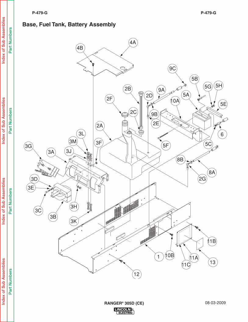
P-479-GP-479-G
Base, Fuel Tank, Battery Assembly
Ind
exo
fS
ubA
ssem
blie
sIn
dex
of
Sub
Ass
emb
lies
Ind
exo
fS
ubA
ssem
blie
sIn
dex
of
Sub
Ass
emb
lies
Par
tN
umb
ers
Par
tN
umb
ers
Par
tN
umb
ers
Par
tN
umb
ers
3G
4B4A
2A
2F
2C
2B
2E
5F
2D
9B
9A
9C
5H5G
5B
5A10A
2G8A
8B
6
5E
5C
13
11B
11A11C
1
12
10B
3B3C
3K
3H
3E
3D
3A
3F
3L
3M
3J
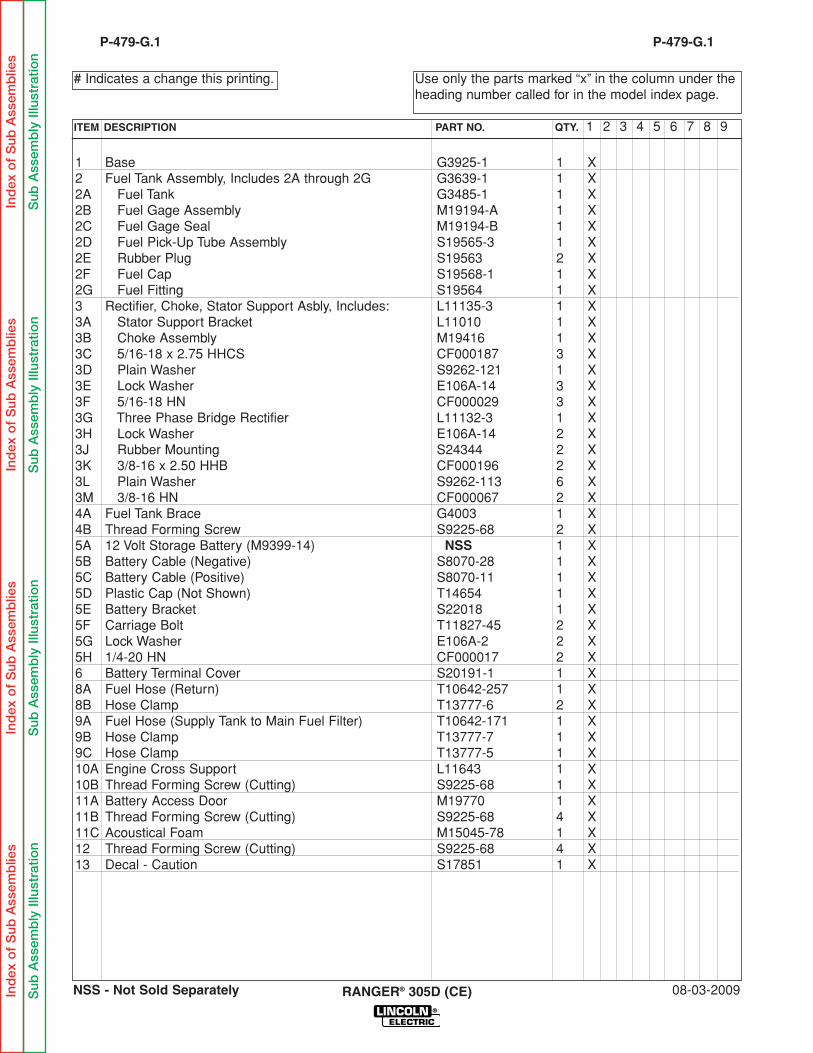
1 Base G3925-1 1 X2 Fuel Tank Assembly, Includes 2A through 2G G3639-1 1 X2A Fuel Tank G3485-1 1 X2B Fuel Gage Assembly M19194-A 1 X2C Fuel Gage Seal M19194-B 1 X2D Fuel Pick-Up Tube Assembly S19565-3 1 X2E Rubber Plug S19563 2 X2F Fuel Cap S19568-1 1 X2G Fuel Fitting S19564 1 X3 Rectifier, Choke, Stator Support Asbly, Includes: L11135-3 1 X3A Stator Support Bracket L11010 1 X3B Choke Assembly M19416 1 X3C 5/16-18 x 2.75 HHCS CF000187 3 X3D Plain Washer S9262-121 1 X3E Lock Washer E106A-14 3 X3F 5/16-18 HN CF000029 3 X3G Three Phase Bridge Rectifier L11132-3 1 X3H Lock Washer E106A-14 2 X3J Rubber Mounting S24344 2 X3K 3/8-16 x 2.50 HHB CF000196 2 X3L Plain Washer S9262-113 6 X3M 3/8-16 HN CF000067 2 X4A Fuel Tank Brace G4003 1 X4B Thread Forming Screw S9225-68 2 X5A 12 Volt Storage Battery (M9399-14) NSS 1 X5B Battery Cable (Negative) S8070-28 1 X5C Battery Cable (Positive) S8070-11 1 X5D Plastic Cap (Not Shown) T14654 1 X5E Battery Bracket S22018 1 X5F Carriage Bolt T11827-45 2 X5G Lock Washer E106A-2 2 X5H 1/4-20 HN CF000017 2 X6 Battery Terminal Cover S20191-1 1 X8A Fuel Hose (Return) T10642-257 1 X8B Hose Clamp T13777-6 2 X9A Fuel Hose (Supply Tank to Main Fuel Filter) T10642-171 1 X9B Hose Clamp T13777-7 1 X9C Hose Clamp T13777-5 1 X10A Engine Cross Support L11643 1 X10B Thread Forming Screw (Cutting) S9225-68 1 X11A Battery Access Door M19770 1 X11B Thread Forming Screw (Cutting) S9225-68 4 X11C Acoustical Foam M15045-78 1 X12 Thread Forming Screw (Cutting) S9225-68 4 X13 Decal - Caution S17851 1 X
08-03-2009RANGER® 305D (CE)
Use only the parts marked “x” in the column under theheading number called for in the model index page.
# Indicates a change this printing.
P-479-G.1
ITEM DESCRIPTION PART NO. QTY. 1 2 3 4 5 6 7 8 9
P-479-G.1
Ind
exo
fS
ubA
ssem
blie
sIn
dex
of
Sub
Ass
emb
lies
Ind
exo
fS
ubA
ssem
blie
sIn
dex
of
Sub
Ass
emb
lies
Sub
Ass
emb
lyIll
ustr
atio
nS
ubA
ssem
bly
Illus
trat
ion
Sub
Ass
emb
lyIll
ustr
atio
nS
ubA
ssem
bly
Illus
trat
ion
NSS - Not Sold Separately
RANGER® 305D (CE) 08-03-2009
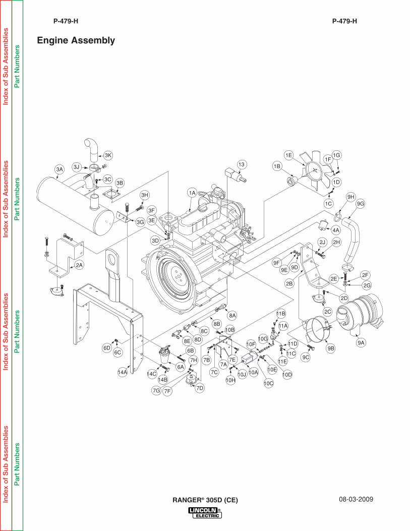
P-479-HP-479-H
Engine Assembly
Ind
exo
fS
ubA
ssem
blie
sIn
dex
of
Sub
Ass
emb
lies
Ind
exo
fS
ubA
ssem
blie
sIn
dex
of
Sub
Ass
emb
lies
Par
tN
umb
ers
Par
tN
umb
ers
Par
tN
umb
ers
Par
tN
umb
ers
14C14A
6D6C
14B
7D
7E7A
7C 10A10J
10C
10E10D
10G11D
11C
11E
11A
10F
10H
10B
7B
7F7G
7H
8E
6B
6A
8A 11B
8B8C
8D
2E2F
9G9H
2G
2C
9A9B
9C
9F9E 9D
2D
2B
2A
3B3C
3J
3K
3G 3E
3F
3D
3H
13
2H
4A
2J
1G1F
1E
1B
1A
1C
1D
3A
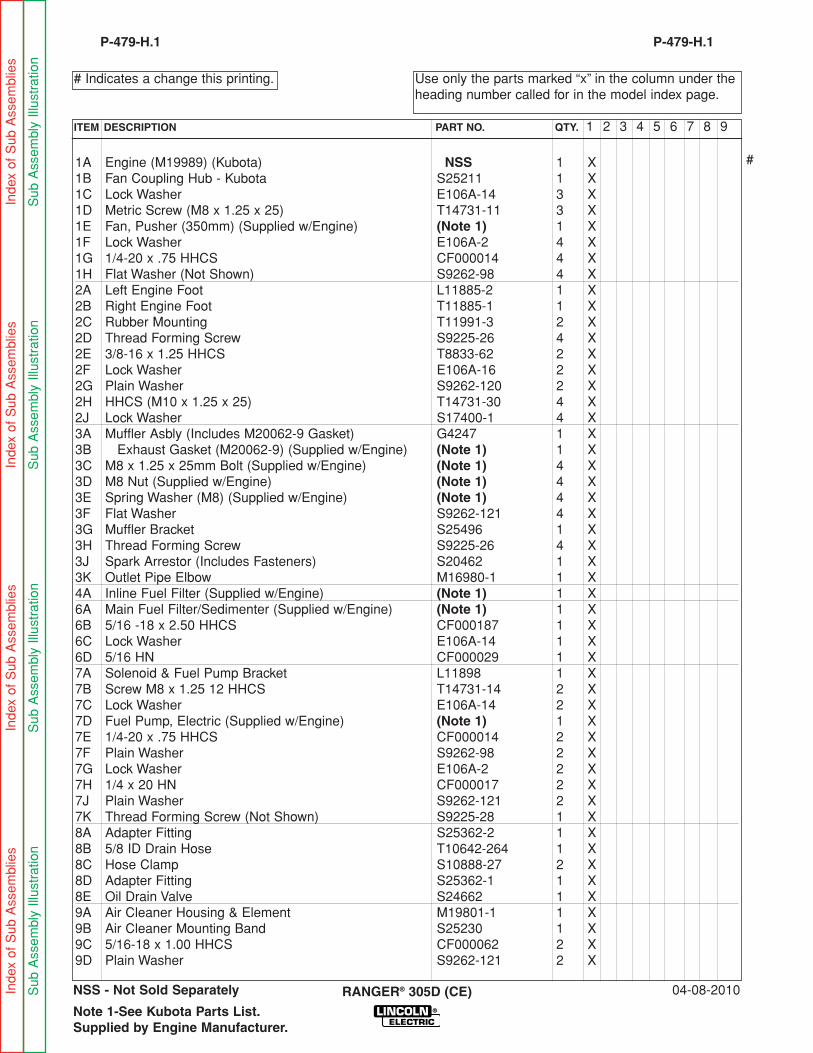
1A Engine (M19989) (Kubota) NSS 1 X1B Fan Coupling Hub - Kubota S25211 1 X1C Lock Washer E106A-14 3 X1D Metric Screw (M8 x 1.25 x 25) T14731-11 3 X1E Fan, Pusher (350mm) (Supplied w/Engine) (Note 1) 1 X1F Lock Washer E106A-2 4 X1G 1/4-20 x .75 HHCS CF000014 4 X1H Flat Washer (Not Shown) S9262-98 4 X2A Left Engine Foot L11885-2 1 X2B Right Engine Foot T11885-1 1 X2C Rubber Mounting T11991-3 2 X2D Thread Forming Screw S9225-26 4 X2E 3/8-16 x 1.25 HHCS T8833-62 2 X2F Lock Washer E106A-16 2 X2G Plain Washer S9262-120 2 X2H HHCS (M10 x 1.25 x 25) T14731-30 4 X2J Lock Washer S17400-1 4 X3A Muffler Asbly (Includes M20062-9 Gasket) G4247 1 X3B Exhaust Gasket (M20062-9) (Supplied w/Engine) (Note 1) 1 X3C M8 x 1.25 x 25mm Bolt (Supplied w/Engine) (Note 1) 4 X3D M8 Nut (Supplied w/Engine) (Note 1) 4 X3E Spring Washer (M8) (Supplied w/Engine) (Note 1) 4 X3F Flat Washer S9262-121 4 X3G Muffler Bracket S25496 1 X3H Thread Forming Screw S9225-26 4 X3J Spark Arrestor (Includes Fasteners) S20462 1 X3K Outlet Pipe Elbow M16980-1 1 X4A Inline Fuel Filter (Supplied w/Engine) (Note 1) 1 X6A Main Fuel Filter/Sedimenter (Supplied w/Engine) (Note 1) 1 X6B 5/16 -18 x 2.50 HHCS CF000187 1 X6C Lock Washer E106A-14 1 X6D 5/16 HN CF000029 1 X7A Solenoid & Fuel Pump Bracket L11898 1 X7B Screw M8 x 1.25 12 HHCS T14731-14 2 X7C Lock Washer E106A-14 2 X7D Fuel Pump, Electric (Supplied w/Engine) (Note 1) 1 X7E 1/4-20 x .75 HHCS CF000014 2 X7F Plain Washer S9262-98 2 X7G Lock Washer E106A-2 2 X7H 1/4 x 20 HN CF000017 2 X7J Plain Washer S9262-121 2 X7K Thread Forming Screw (Not Shown) S9225-28 1 X8A Adapter Fitting S25362-2 1 X8B 5/8 ID Drain Hose T10642-264 1 X8C Hose Clamp S10888-27 2 X8D Adapter Fitting S25362-1 1 X8E Oil Drain Valve S24662 1 X9A Air Cleaner Housing & Element M19801-1 1 X9B Air Cleaner Mounting Band S25230 1 X9C 5/16-18 x 1.00 HHCS CF000062 2 X9D Plain Washer S9262-121 2 X
04-08-2010RANGER® 305D (CE)
Use only the parts marked “x” in the column under theheading number called for in the model index page.
# Indicates a change this printing.
P-479-H.1
ITEM DESCRIPTION PART NO. QTY. 1 2 3 4 5 6 7 8 9
P-479-H.1
Inde
x of
Sub
Ass
embl
ies
Inde
x of
Sub
Ass
embl
ies
Inde
x of
Sub
Ass
embl
ies
Inde
x of
Sub
Ass
embl
ies
Sub
Ass
embl
y Ill
ustr
atio
nS
ub A
ssem
bly
Illus
trat
ion
Sub
Ass
embl
y Ill
ustr
atio
nS
ub A
ssem
bly
Illus
trat
ion
Note 1-See Kubota Parts List.Supplied by Engine Manufacturer.
NSS - Not Sold Separately
#
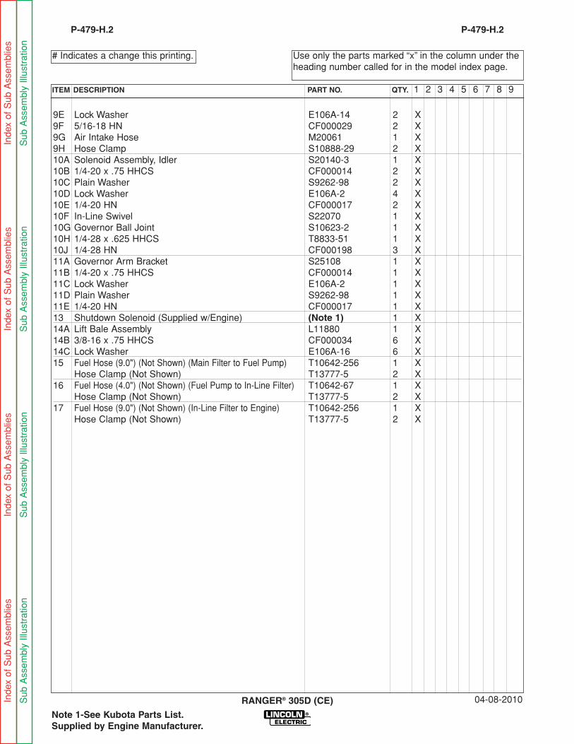
9E Lock Washer E106A-14 2 X9F 5/16-18 HN CF000029 2 X9G Air Intake Hose M20061 1 X9H Hose Clamp S10888-29 2 X10A Solenoid Assembly, Idler S20140-3 1 X10B 1/4-20 x .75 HHCS CF000014 2 X10C Plain Washer S9262-98 2 X10D Lock Washer E106A-2 4 X10E 1/4-20 HN CF000017 2 X10F In-Line Swivel S22070 1 X10G Governor Ball Joint S10623-2 1 X10H 1/4-28 x .625 HHCS T8833-51 1 X10J 1/4-28 HN CF000198 3 X11A Governor Arm Bracket S25108 1 X11B 1/4-20 x .75 HHCS CF000014 1 X11C Lock Washer E106A-2 1 X11D Plain Washer S9262-98 1 X11E 1/4-20 HN CF000017 1 X13 Shutdown Solenoid (Supplied w/Engine) (Note 1) 1 X14A Lift Bale Assembly L11880 1 X14B 3/8-16 x .75 HHCS CF000034 6 X14C Lock Washer E106A-16 6 X15 Fuel Hose (9.0") (Not Shown) (Main Filter to Fuel Pump) T10642-256 1 X
Hose Clamp (Not Shown) T13777-5 2 X16 Fuel Hose (4.0") (Not Shown) (Fuel Pump to In-Line Filter) T10642-67 1 X
Hose Clamp (Not Shown) T13777-5 2 X17 Fuel Hose (9.0") (Not Shown) (In-Line Filter to Engine) T10642-256 1 X
Hose Clamp (Not Shown) T13777-5 2 X
04-08-2010RANGER® 305D (CE)
Use only the parts marked “x” in the column under theheading number called for in the model index page.
# Indicates a change this printing.
P-479-H.2
ITEM DESCRIPTION PART NO. QTY. 1 2 3 4 5 6 7 8 9
P-479-H.2
Inde
x of
Sub
Ass
embl
ies
Inde
x of
Sub
Ass
embl
ies
Inde
x of
Sub
Ass
embl
ies
Inde
x of
Sub
Ass
embl
ies
Sub
Ass
embl
y Ill
ustr
atio
nS
ub A
ssem
bly
Illus
trat
ion
Sub
Ass
embl
y Ill
ustr
atio
nS
ub A
ssem
bly
Illus
trat
ion
Note 1-See Kubota Parts List.Supplied by Engine Manufacturer.
RANGER® 305D (CE)
NOTES
Ind
exo
fS
ubA
ssem
blie
sIn
dex
of
Sub
Ass
emb
lies
Ind
exo
fS
ubA
ssem
blie
sIn
dex
of
Sub
Ass
emb
lies
RANGER® 305D (CE) 10-05-2010
P-479-JP-479-J
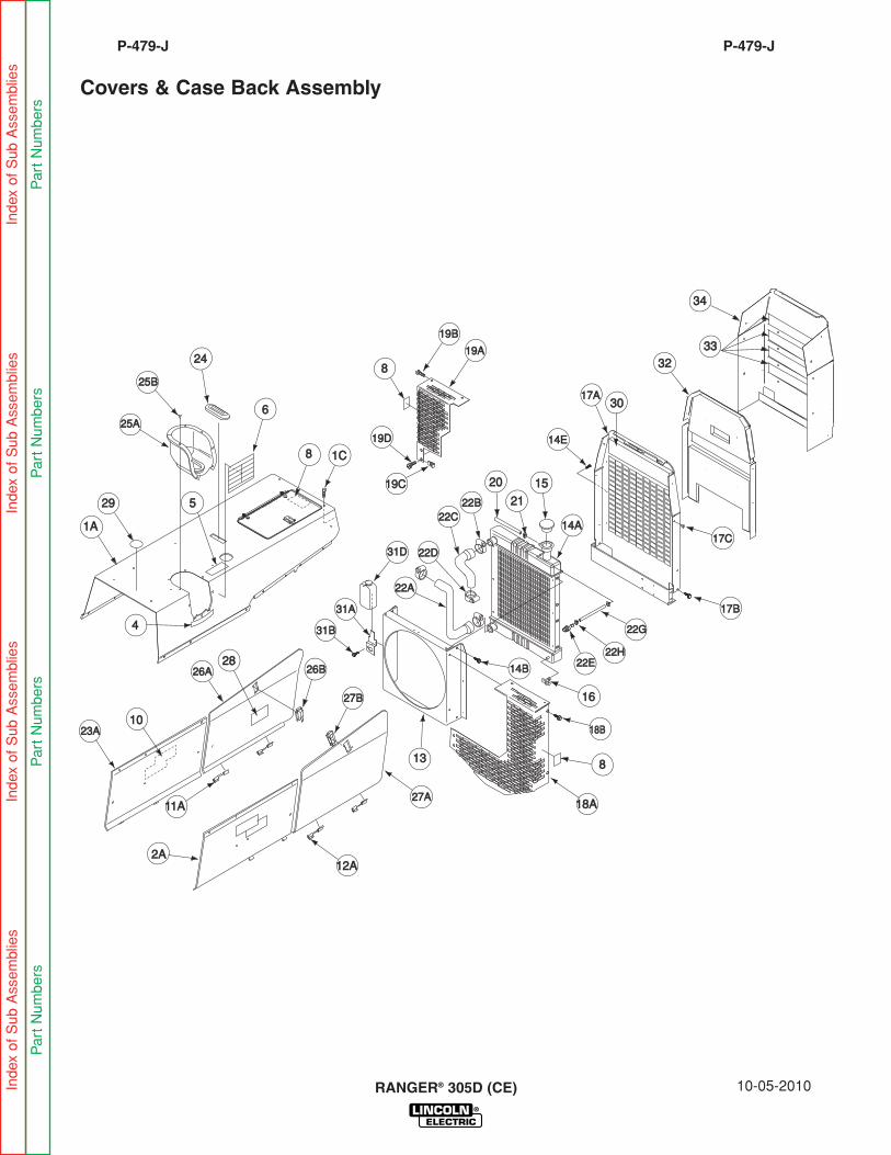
Covers & Case Back Assembly
14E14E
3232
3434
3333
22C22C22B22B
3030
22A22A
15152020
2121
17A17A
17C17C
17B17B
22G22G
22H22H22E22E
1616
18B18B
18A18A
14B14B
14A14A
1313
31D31D
31B31B
31A31A
88
26A26A 26B26B2828
101023A23A
11A11A
22D22D
1A1A
2929
2424
55
25A25A
25B25B
88
66
1C1C
44
19D19D
19C19C
88
19B19B
19A19A
27B27B
12A12A
27A27A
2A2A
Index of Sub Assem
blies
Index of Sub Assem
blies
Index of Sub Assem
blies
Index of Sub Assem
blies
Part Num
bers
Part Num
bers
Part Num
bers
Part Num
bers

1A Roof Assembly G4405-1 1 X X1C Thread Forming Screw S9225-68 16 X X2A Right Case Side Assembly G4405-2 1 X X2B Thread Forming Screw (Not Shown) S9225-68 3 X X4 Fuel Capacity Decal L12037 1 X X5 Fuel Warning Decal T13086-26 1 X X6 Warning Label (International) L8064-1 1 X X8 Warning Decal T13086-62 2 X X9 Wiring Diagram (Not Shown) G4226 1 X •
Wiring Diagram (Not Shown) G4409 1 • X10 Logo Decal S11893-4 2 X X11A Hinge Assembly S24295-1 2 X X11B Rivet (Not Shown) T12584-9 4 X X12A Hinge Assembly S24295-2 2 X X12B Rivet (Not Shown) T12584-9 2 X X13 Fan Shroud G4245 1 X X14A Radiator G3115-1 1 X X14B Thread Forming Screw S9225-26 4 X X14C Plain Washer (Not Shown) S9262-121 4 X X14D Lock Washer (Not Shown) E106A-14 4 X X14E Thread Forming Screw (Not Shown) S9225-68 6 X X15 Radiator Cap S9970-2 1 X X16 Drain Cock T9956 1 X X17A Case Back G4243 1 X X17B Thread Forming Screw S9225-68 8 X X17C Fastener Button T14659-1 4 X X18A Fan Guard (Right) G4058-1 1 X X18B Thread Forming Screw S9225-68 4 X X19A Fan Guard (Left) G4060-1 1 X X19B Thread Forming Screw S9225-68 4 X X19C Speed Nut T11525-5 2 X X19D Thread Forming Screw S9225-66 2 X X20 Over Flow Hose (Radiator to Coolant Bottle) T10642-236 1 X X21 Hose Clamp (Over Flow Hose) T13777-5 2 X X22A Lower Radiator Hose L11881 1 X X22B Hose Clamp S10888-16 2 X X22C Upper Radiator Hose M20064 1 X X22D Hose Clamp S10888-16 2 X X22E Hose Fitting, Brass S25524 1 X X22G Flex Hose (Ref. Thermostat to Radiator) T10642-263 1 X X22H Clamps S10888-35 2 X X23A Left Case Side Assembly G4405-3 1 X X23B Thread Forming Screw (Not Shown) S9225-68 3 X X24 Cover Seal S12934-1 1 X X25A Fuel Trough G3595 1 X X25B Rivet (Plastic) T14951-1 8 X X26A Left Engine Cover Assembly, Includes: G4405-5 1 X X26B Latch S24694 1 X X27A Right Engine Cover Assembly, Includes: G4405-4 1 X X27B Latch S24694 1 X X28 Oil Drain Procedure Decal (L12037-2) (Part of L12037) NSS 1 X X
10-05-2010RANGER® 305D (CE)
Use only the parts marked “x” in the column under theheading number called for in the model index page.
# Indicates a change this printing.
P-479-J.1
ITEM DESCRIPTION PART NO. QTY. 1 2 3 4 5 6 7 8 9
P-479-J.1
NSS - Not Sold Separately
####
Index of Sub Assem
blies
Index of Sub Assem
blies
Index of Sub Assem
blies
Index of Sub Assem
blies
Sub
Assem
bly Illustration
Sub
Assem
bly Illustration
Sub Assem
bly Illustration
Sub Assem
bly Illustration
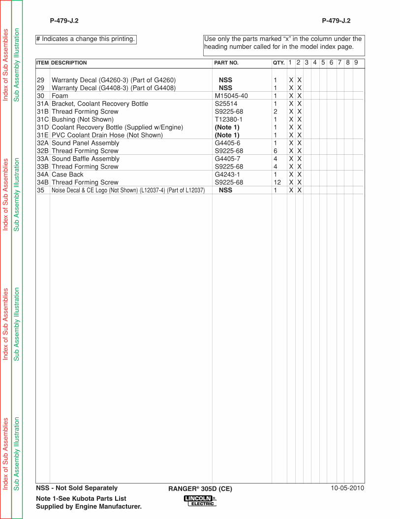
29 Warranty Decal (G4260-3) (Part of G4260) NSS 1 X X29 Warranty Decal (G4408-3) (Part of G4408) NSS 1 X X30 Foam M15045-40 1 X X31A Bracket, Coolant Recovery Bottle S25514 1 X X31B Thread Forming Screw S9225-68 2 X X31C Bushing (Not Shown) T12380-1 1 X X31D Coolant Recovery Bottle (Supplied w/Engine) (Note 1) 1 X X31E PVC Coolant Drain Hose (Not Shown) (Note 1) 1 X X32A Sound Panel Assembly G4405-6 1 X X32B Thread Forming Screw S9225-68 6 X X33A Sound Baffle Assembly G4405-7 4 X X33B Thread Forming Screw S9225-68 4 X X34A Case Back G4243-1 1 X X34B Thread Forming Screw S9225-68 12 X X35 Noise Decal & CE Logo (Not Shown) (L12037-4) (Part of L12037) NSS 1 X X
10-05-2010RANGER® 305D (CE)
Use only the parts marked “x” in the column under theheading number called for in the model index page.
# Indicates a change this printing.
P-479-J.2
ITEM DESCRIPTION PART NO. QTY. 1 2 3 4 5 6 7 8 9
P-479-J.2
Note 1-See Kubota Parts ListSupplied by Engine Manufacturer.
NSS - Not Sold SeparatelyIndex of Sub Assem
blies
Index of Sub Assem
blies
Index of Sub Assem
blies
Index of Sub Assem
blies
Sub
Assem
bly Illustration
Sub
Assem
bly Illustration
Sub Assem
bly Illustration
Sub Assem
bly Illustration


