PART B Chapter 2 Contents - National Masonry · 70 60 50 40 30 20 10 0 1000–4000 Hz ... Part...
13
PART B:CHAPTER 2 Acoustics PART B Chapter 2 Acoustics This chapter describes the acoustic performance of concrete masonry used in buildings to: n Reduce reflected noise within a building, and n Resist the passage of airborne and impact sounds through walls, as necessary by the National Construction Code (NCC) – Building Code of Australia (BCA) Contents 2.1 BASIS OF DESIGN 2.2 DESIGN REQUIREMENTS 2.3 STANDARD DESIGNS 2.4 WORKED EXAMPLE
Transcript of PART B Chapter 2 Contents - National Masonry · 70 60 50 40 30 20 10 0 1000–4000 Hz ... Part...

PART B:CHAPTER 2Acoustics
PART B Chapter 2AcousticsThis chapter describes the acoustic performance of concrete masonry used in buildings to:
n Reduce reflected noise within a building, and
n Resist the passage of airborne and impact sounds through walls, as necessary by the National Construction Code (NCC) – Building Code of Australia (BCA)
Contents2.1 BAsis of design
2.2 design RequiRemenTs
2.3 sTAndARd designs
2.4 woRked exAmPle
PART B:CHAPTER 2Acoustics
2.1.1 BACkgRound
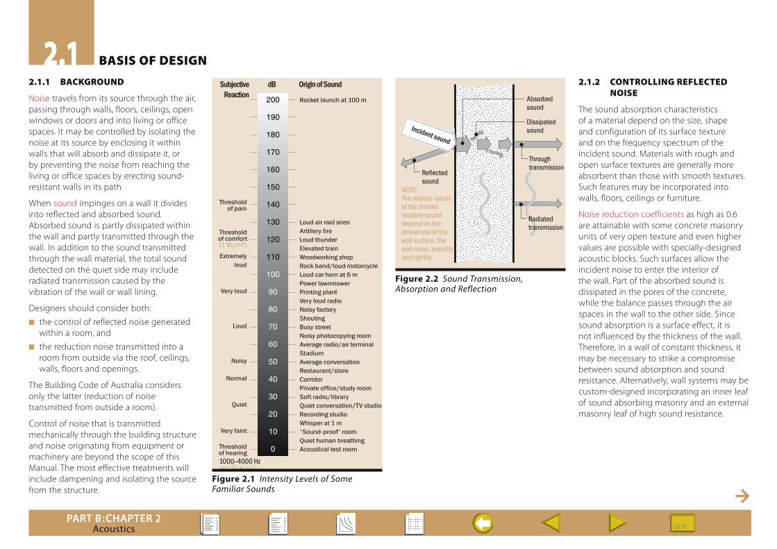
Noise travels from its source through the air, passing through walls, floors, ceilings, open windows or doors and into living or office spaces. It may be controlled by isolating the noise at its source by enclosing it within walls that will absorb and dissipate it, or by preventing the noise from reaching the living or office spaces by erecting sound-resistant walls in its path.
When sound impinges on a wall it divides into reflected and absorbed sound. Absorbed sound is partly dissipated within the wall and partly transmitted through the wall. In addition to the sound transmitted through the wall material, the total sound detected on the quiet side may include radiated transmission caused by the vibration of the wall or wall lining.
Designers should consider both:
n the control of reflected noise generated within a room, and
n the reduction noise transmitted into a room from outside via the roof, ceilings, walls, floors and openings.
The Building Code of Australia considers only the latter (reduction of noise transmitted from outside a room).
Control of noise that is transmitted mechanically through the building structure and noise originating from equipment or machinery are beyond the scope of this Manual. The most effective treatments will include dampening and isolating the source from the structure.
2.1.2 ConTRolling RefleCTed noise
The sound absorption characteristics of a material depend on the size, shape and configuration of its surface texture and on the frequency spectrum of the incident sound. Materials with rough and open surface textures are generally more absorbent than those with smooth textures. Such features may be incorporated into walls, floors, ceilings or furniture.
Noise reduction coefficients as high as 0.6 are attainable with some concrete masonry units of very open texture and even higher values are possible with specially-designed acoustic blocks. Such surfaces allow the incident noise to enter the interior of the wall. Part of the absorbed sound is dissipated in the pores of the concrete, while the balance passes through the air spaces in the wall to the other side. Since sound absorption is a surface effect, it is not influenced by the thickness of the wall. Therefore, in a wall of constant thickness, it may be necessary to strike a compromise between sound absorption and sound resistance. Alternatively, wall systems may be custom-designed incorporating an inner leaf of sound absorbing masonry and an external masonry leaf of high sound resistance.
2.1 BAsis of design
Rocket launch at 100 m
Loud air raid sirenArtillery fireLoud thunderElevated trainWoodworking shopRock band/loud motorcycleLoud car horn at 6 mPower lawnmowerPrinting plantVery loud radioNoisy factoryShoutingBusy streetNoisy photocopying roomAverage radio/air terminalStadiumAverage conversationRestaurant/storeCorridorPrivate office/study roomSoft radio/libraryQuiet conversation/TV studioRecording studioWhisper at 1 m'Sound-proof' roomQuiet human breathingAcoustical test room
SubjectiveReaction
Thresholdof pain
Thresholdof comfort(1 W/m2)
Extremelyloud
Very loud
Loud
Noisy
Normal
Quiet
Very faint
Thresholdof hearing
dB Origin of Sound
200
190
180
170
160
150
140
130
120
110
100
90
80
70
60
50
40
30
20
10
0
1000–4000 Hz(10-12 W/m2)
Reflectedsound
Incident sound
Absorbedsound
Dissipatedsound
Throughtransmission
Radiatedtransmission
NOTE:The relative valuesof the dividedincident sounddepend on thedenseness of thewall surface, thewall mass, porosityand rigidity
Figure 2.1 Intensity Levels of Some Familiar Sounds
Figure 2.2 Sound Transmission, Absorption and Reflection

PART B:CHAPTER 2Acoustics
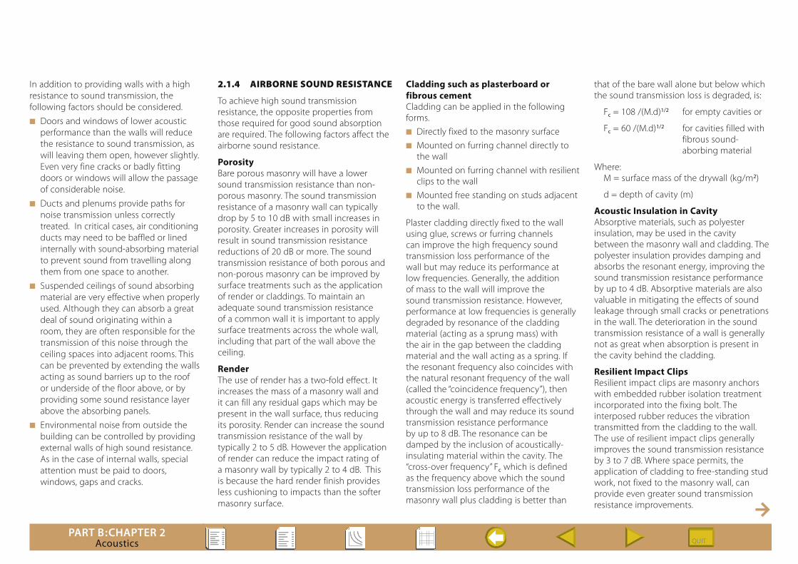
Sound absorption is maximised with units consisting of lightweight aggregates or units with unpainted open texture and high internal porosity, such as no-fines concrete. Unrendered and unpainted concrete masonry absorbs more sound than surface-treated walls. A light spray painting reduces sound absorption only marginally, although paint that is brushed on tends to seal the outer pores, reducing sound entry and dissipation.
Not all reflected sound is objectionable. It would be most undesirable to have a room in which all sound generated from within was absorbed. Such a room would be described as acoustically dead and could have unpleasant psychological effects on occupants. Sound-absorbing materials are commonly used to quieten noisy rooms such as airport lounges or hotel bars. Excessive echoing within a building can interfere with hearing. Sound absorbing materials may be used to adjust the reverberation time (echo time) of auditoriums, theatres or concert halls to achieve a satisfactory clarity and volume of sound for the particular type of performance to be given.
A Noise Reduction Coefficient is a measure of the ability of a wall to absorb sound. Figure 2.3 shows the estimated Noise Reduction Coefficients for concrete masonry walls with various combinations of surface texture and finish. Although these figures provide a useful guide, in critical situations tests should be carried out on the actual materials intended for use.
See various references from Portland Cement Association (USA) and National Concrete Masonry Association (USA) in Part B:Chapter 1, Clause 1.13.2.
2.1.3 ConTRolling TRAnsmiTTed noise
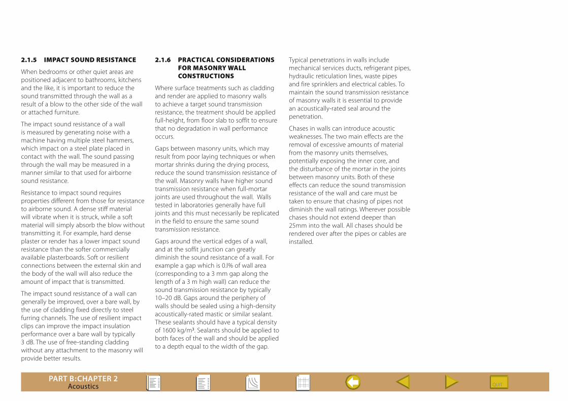
There are three distinct modes of sound transmission through walls (see Figure 2.4).
n At frequencies below the resonant frequency of the wall, the stiffness of the wall is of greatest importance, and the mass and damping have little effect. As the frequency increases, the mass of the wall becomes more important and the wall may start to resonate.
n At frequencies beyond those which cause resonance, the mass of the wall provides a damping effect. It is in this region that concrete masonry (being a “high mass” system) provides a significant advantage
over lightweight alternatives. Although the mechanism is not well understood, the resistance to sound transmission increases by approximately 6 dB for each doubling of the frequency or for each doubling of the mass.
n At frequencies above the critical frequency, the coincidence of the sound waves control the behaviour. For masonry, the critical frequency is relatively low when compared to other lighter materials. A coincidence dip immediately above the critical frequency indicates a loss in airborne sound resistance.
Spray paint
Porous surface Dense surface
2 coats 1 coatUntreated
surface
0
0.1
0.2
0.3
0.4
0.5
0.6
0.7
0
0.1
0.2
0.3
0.4
0.5
Nois
e Re
duct
ion
Coef
ficie
nts
Nois
e Re
duct
ion
Coef
ficie
nts
Brush paint2 coats 1 coat
Spray paint2 coats 1 coat
Untreatedsurface
Brush paint2 coats 1 coat
LIGHTWEIGHT AGGREGATE UNITS
DENSEWEIGHT AGGREGATE UNITS
Figure 2.3 Estimated Noise Reduction Coefficients for Concrete Masonry Walls
Stiffness
controlled
Mass
controlled
Coincidence
controlled
Resonance
Criticalfrequency
Coincidence dip
Mass Law predicts6 dB per octave
Frequency (Hz)
Soun
d Tr
ansm
issi
on L
oss
(dB)
Figure 2.4 Characteristic Sound-Transmission-Loss Curve [After EBS Technical Study 48]
PART B:CHAPTER 2Acoustics
In addition to providing walls with a high resistance to sound transmission, the following factors should be considered.
n Doors and windows of lower acoustic performance than the walls will reduce the resistance to sound transmission, as will leaving them open, however slightly. Even very fine cracks or badly fitting doors or windows will allow the passage of considerable noise.
n Ducts and plenums provide paths for noise transmission unless correctly treated. In critical cases, air conditioning ducts may need to be baffled or lined internally with sound-absorbing material to prevent sound from travelling along them from one space to another.
n Suspended ceilings of sound absorbing material are very effective when properly used. Although they can absorb a great deal of sound originating within a room, they are often responsible for the transmission of this noise through the ceiling spaces into adjacent rooms. This can be prevented by extending the walls acting as sound barriers up to the roof or underside of the floor above, or by providing some sound resistance layer above the absorbing panels.
n Environmental noise from outside the building can be controlled by providing external walls of high sound resistance. As in the case of internal walls, special attention must be paid to doors, windows, gaps and cracks.
2.1.4 AiRBoRne sound ResisTAnCe
To achieve high sound transmission resistance, the opposite properties from those required for good sound absorption are required. The following factors affect the airborne sound resistance.
PorosityBare porous masonry will have a lower sound transmission resistance than non-porous masonry. The sound transmission resistance of a masonry wall can typically drop by 5 to 10 dB with small increases in porosity. Greater increases in porosity will result in sound transmission resistance reductions of 20 dB or more. The sound transmission resistance of both porous and non-porous masonry can be improved by surface treatments such as the application of render or claddings. To maintain an adequate sound transmission resistance of a common wall it is important to apply surface treatments across the whole wall, including that part of the wall above the ceiling.
RenderThe use of render has a two-fold effect. It increases the mass of a masonry wall and it can fill any residual gaps which may be present in the wall surface, thus reducing its porosity. Render can increase the sound transmission resistance of the wall by typically 2 to 5 dB. However the application of render can reduce the impact rating of a masonry wall by typically 2 to 4 dB. This is because the hard render finish provides less cushioning to impacts than the softer masonry surface.
Cladding such as plasterboard or fibrous cementCladding can be applied in the following forms.n Directly fixed to the masonry surfacen Mounted on furring channel directly to
the walln Mounted on furring channel with resilient
clips to the walln Mounted free standing on studs adjacent
to the wall.
Plaster cladding directly fixed to the wall using glue, screws or furring channels can improve the high frequency sound transmission loss performance of the wall but may reduce its performance at low frequencies. Generally, the addition of mass to the wall will improve the sound transmission resistance. However, performance at low frequencies is generally degraded by resonance of the cladding material (acting as a sprung mass) with the air in the gap between the cladding material and the wall acting as a spring. If the resonant frequency also coincides with the natural resonant frequency of the wall (called the “coincidence frequency”), then acoustic energy is transferred effectively through the wall and may reduce its sound transmission resistance performance by up to 8 dB. The resonance can be damped by the inclusion of acoustically-insulating material within the cavity. The “cross-over frequency” Fc which is defined as the frequency above which the sound transmission loss performance of the masonry wall plus cladding is better than
that of the bare wall alone but below which the sound transmission loss is degraded, is:
Fc = 108 /(M.d)1/2 for empty cavities or
Fc = 60 /(M.d)1/2 for cavities filled with fibrous sound- aborbing material
Where: M = surface mass of the drywall (kg/m2)
d = depth of cavity (m)
Acoustic Insulation in Cavity Absorptive materials, such as polyester insulation, may be used in the cavity between the masonry wall and cladding. The polyester insulation provides damping and absorbs the resonant energy, improving the sound transmission resistance performance by up to 4 dB. Absorptive materials are also valuable in mitigating the effects of sound leakage through small cracks or penetrations in the wall. The deterioration in the sound transmission resistance of a wall is generally not as great when absorption is present in the cavity behind the cladding.
Resilient Impact ClipsResilient impact clips are masonry anchors with embedded rubber isolation treatment incorporated into the fixing bolt. The interposed rubber reduces the vibration transmitted from the cladding to the wall. The use of resilient impact clips generally improves the sound transmission resistance by 3 to 7 dB. Where space permits, the application of cladding to free-standing stud work, not fixed to the masonry wall, can provide even greater sound transmission resistance improvements.
PART B:CHAPTER 2Acoustics
2.1.5 imPACT sound ResisTAnCe
When bedrooms or other quiet areas are positioned adjacent to bathrooms, kitchens and the like, it is important to reduce the sound transmitted through the wall as a result of a blow to the other side of the wall or attached furniture.
The impact sound resistance of a wall is measured by generating noise with a machine having multiple steel hammers, which impact on a steel plate placed in contact with the wall. The sound passing through the wall may be measured in a manner similar to that used for airborne sound resistance.
Resistance to impact sound requires properties different from those for resistance to airborne sound. A dense stiff material will vibrate when it is struck, while a soft material will simply absorb the blow without transmitting it. For example, hard dense plaster or render has a lower impact sound resistance than the softer commercially available plasterboards. Soft or resilient connections between the external skin and the body of the wall will also reduce the amount of impact that is transmitted.
The impact sound resistance of a wall can generally be improved, over a bare wall, by the use of cladding fixed directly to steel furring channels. The use of resilient impact clips can improve the impact insulation performance over a bare wall by typically 3 dB. The use of free-standing cladding without any attachment to the masonry will provide better results.
2.1.6 PRACTiCAl ConsideRATions foR mAsonRy wAll ConsTRuCTions
Where surface treatments such as cladding and render are applied to masonry walls to achieve a target sound transmission resistance, the treatment should be applied full-height, from floor slab to soffit to ensure that no degradation in wall performance occurs.
Gaps between masonry units, which may result from poor laying techniques or when mortar shrinks during the drying process, reduce the sound transmission resistance of the wall. Masonry walls have higher sound transmission resistance when full-mortar joints are used throughout the wall. Walls tested in laboratories generally have full joints and this must necessarily be replicated in the field to ensure the same sound transmission resistance.
Gaps around the vertical edges of a wall, and at the soffit junction can greatly diminish the sound resistance of a wall. For example a gap which is 0.l% of wall area (corresponding to a 3 mm gap along the length of a 3 m high wall) can reduce the sound transmission resistance by typically 10–20 dB. Gaps around the periphery of walls should be sealed using a high-density acoustically-rated mastic or similar sealant. These sealants should have a typical density of 1600 kg/m3. Sealants should be applied to both faces of the wall and should be applied to a depth equal to the width of the gap.
Typical penetrations in walls include mechanical services ducts, refrigerant pipes, hydraulic reticulation lines, waste pipes and fire sprinklers and electrical cables. To maintain the sound transmission resistance of masonry walls it is essential to provide an acoustically-rated seal around the penetration.
Chases in walls can introduce acoustic weaknesses. The two main effects are the removal of excessive amounts of material from the masonry units themselves, potentially exposing the inner core, and the disturbance of the mortar in the joints between masonry units. Both of these effects can reduce the sound transmission resistance of the wall and care must be taken to ensure that chasing of pipes not diminish the wall ratings. Wherever possible chases should not extend deeper than 25mm into the wall. All chases should be rendered over after the pipes or cables are installed.

PART B:CHAPTER 2Acoustics
2.2.1 nATionAl ConsTRuCTion Code – Building Code of AusTRAliA – Volume one RequiRemenTs
These requirements apply to:n Class 2 Buildings, containing two or
more sole-occupancy units, each being a separate dwelling, other than a Class 1 Building. Class 2 Building would include most blocks of home units
n Class 3 Buildings, residential buildings other than Class 1 and Class 2, being the common living place for a number of unrelated people. They include boarding houses, guest houses, hostels or lodging houses, the residential parts of hotels and motels, the residential parts of schools, accommodation for the aged, disabled or children and the staff accommodation areas of health care buildings
n Class 9c Buildings, aged-care buildings.
The sound transmission and insulation requirements are set out in NCC–BCA Vol One Part F5, and the principal points are summarised below. It should be noted that some states have varied these requirements and the means of satisfying them.
The objective set out in NCC–BCA Vol One Clause FO5 is to:
“ … safeguard occupants from illness or loss of amenity as a result of undue sound being transmitted – (a) between adjoining sole-occupancy units; and (b) from common spaces to sole-occupancy units; and
(c) from parts of different classifications to sole occupancy.”
This objective is further expanded for walls in NCC–BCA Vol One Clause FF5.1 NCC–BCA Vol One Clauses FF5.2 and FF5.5, which spell out the particular applications where there are requirements to provide both airborne sound resistance and impact sound resistance. NCC–BCA Vol One Clauses FF5.3 and FF5.6 further state that the sound insulation must not be compromised by doors or pipes. It is worth noting that the NCC–BCA Vol One does not aim to reduce the noise entering a room from outside the building, only to restrict sound passing from room to room or room to public space within the building.
Insitu Verification of WallsNCC–BCA Vol One Clause FV5.2 provides for verification of walls constructed in a building based on insitu tests to AS/NZS 1276.1 or ISO 717.1
Deemed-to-Satisfy ProvisionsNCC–BCA Vol One Clauses F5.0 to F5.7 provide the means of satisfying the performance requirements. The particular requirements of Clause F5.3 for walls may be summarised as follows:
Class 2 and 3 Buildingsn Any walls that separate sole occupancy units in a Class 2 or 3 building:
Rw + Ctr (airborne) not less than 50,
n Any walls that separate a habitable room of a sole occupancy unit in a Class 2 or 3 building from a bathroom, sanitary
compartment, laundry or kitchen of another unit:
Rw + Ctr (airborne) not less than 50, andImpact sound resistance.
Walls requiring impact sound resistance shall consist of two leaves separated by a gap of at least 20 mm and where necessary for structural purposes, connected by resilient ties.
n Any walls that separate a sole occupancy unit in a Class 2 or 3 building from a stairway, public corridor, public lobby or the like:
Rw (airborne) not less than 50
n Any walls that separate a sole occupancy unit in a Class 2 or 3 building from a plant room or lift shaft:
Rw (airborne) not less than 50
n A door assembly incorporated in a wall that separates a sole occupancy unit in a Class 2 or 3 building from stairway, public corridor, public lobby or the like:
Rw (airborne) not less than 30
n Walls required to have a sound insulation shall be constructed to the underside of:
•afloorabove,or •aceilingwiththesameacousticrating,or •aroofabove.
Class 9c Aged-care Buildingsn Any walls that separate sole occupancy
units in a Class 9c building:
Rw (airborne) not less than 45
n Any walls that separate a sole occupancy unit in a Class 9c building from a kitchen or laundry:
Rw (airborne) not less than 45, andImpact sound resistance.
Walls requiring impact sound resistance shall consist of two leaves separated by a gap of at least 20 mm and where necessary for structural purposes, connected by resilient ties.
n Any walls that separate a sole occupancy unit in a Class 9c building from a bathroom, sanitry compartment (not en-suite) plantroom or utilities room:
Rw (airborne) not less than 45
n Walls required to have a sound insulation shall be constructed to the underside of:
•afloorabove,or •aceilingwiththesameacousticrating,or •aroofabove.Alldesignanddetailingshall comply with the requirements of AS 3700 and the NCC–BCA.
2.2 design RequiRemenTs

PART B:CHAPTER 2Acoustics
2.2.2 nATionAl ConsTRuCTion Code – Building Code of AusTRAliA –Volume Two RequiRemenTs
These requirements apply to Class 1 Buildings, single dwelling houses, terrace houses, town houses, row houses and villa houses, boarding houses, hostels, group houses and dual occupancy houses in which not more than twelve persons would normally reside and residential buildings of not more than three storeys and containing not more than two sole-occupancy units, located one above the other and each with separate means of egress to the road or open space.
The sound transmission and insulation requirements are summarised below. It should be noted that some states have varied these requirements and the means of satisfying them.
The objective set out in NCC–BCA Vol Two Clause P2.4.6 is to:
“ … provide insulation against the transmission of airborne … and impact generated sound sufficient to prevent illness or loss of amenity to the occupants”. The extent of the requirement is varied in some states. The objective is further amplified, “The required sound insulation of walls must not be compromised by the incorporation or penetration of a pipe or other service element.”
Insitu Verification of WallsNCC–BCA Vol One Clause 3.8.2 V2.4.6 provides for verification of walls constructed in a building based on insitu tests to AS/NZS 1276.1 or AS/NZS ISO 717.1 (Not applicable in Northern Territory)
Acceptable Construction PracticeNCC–BCA Vol Two Clauses 3.8.6.1 to 3.8.6.4 provide the means of satisfying the performance requirements and may be summarised as follows:
n Walls that separate a room (other than a bathroom, sanitary compartment, laundry or kitchen) of one Class 1 building from a habitable room in an adjoining Class 1 building (dwelling):
Rw + Ctr (airborne) not less than 50
n Walls that separate a bathroom, sanitary compartment, laundry or kitchen of one Class 1 building from a habitable room (other than a kitchen) in an adjoining Class 1 building (dwelling):
Rw + Ctr (airborne) not less than 50, andDiscontinuous construction (i.e. for masonry, a minimum of 20 mm cavity between two separate leaves, which if required for structural purposes, may be connected with resilient ties)
n Walls required to be detailed in accordance with NCC–BCA Vol Two Clause 3.8.6.3, which make provision for the sealing of sound insulated walls at junctions with perimeter wall and roof cladding. This clause also requires that masonry joints be filled and provides for sound insulated articulation joints.
n NCC–BCA Vol Two Clause 3.8.6.4 makes provision for services in uninsulated walls.
PART B:CHAPTER 2Acoustics
All design and detailing shall comply with the requirements of AS 3700 and the NCC–BCA.
All control joints, chases and openings shall be insulated such that the acoustic attenuation of the wall is maintained.
Mortar joints shall be as follows.
n All bed joints and perpendicular joints for solid or cored masonry shall be completely filled with Type M3 or Type M4 mortar.
n All bed joints and perpendicular joints for hollow masonry shall include ironed M3 or M4 mortar to at least the full thickness of the face shell at their widest point.
All masonry units shall comply with the General Specification set out in this manual (Part C:Chapter 2).
Deemed-To-Satisfy ConstructionThe National Construction Code (NCC) – Building Code of Australia Volumes One and Two provide a limited number of construction types that are deemed to satisfy the performance requirements for airborne sound attenuation and impact sound attenuation.
Sound Attenuation TestsMasonry manufacturers also have a significant body of test data on the acoustic performance of various masonry wall systems (some incorporating various combinations of other components such as render, plasterboard, resilient ties, furring channels and insulation). It is recommended that designers contact the masonry
manufacturers to obtain this data and specific recommendations. Some typical test results for sound transmission resistance of masonry walls are demonstrate in the following Charts.
CHART index
1 STC Results –Masonry walls with and without various claddings
2 STC Test Results –Bare masonry walls
3 STC Test Results –Rendered masonry walls
4 STC Test Results –Masonry walls with plaster cladding
2.3 sTAndARd designs
PART B:CHAPTER 2Acoustics
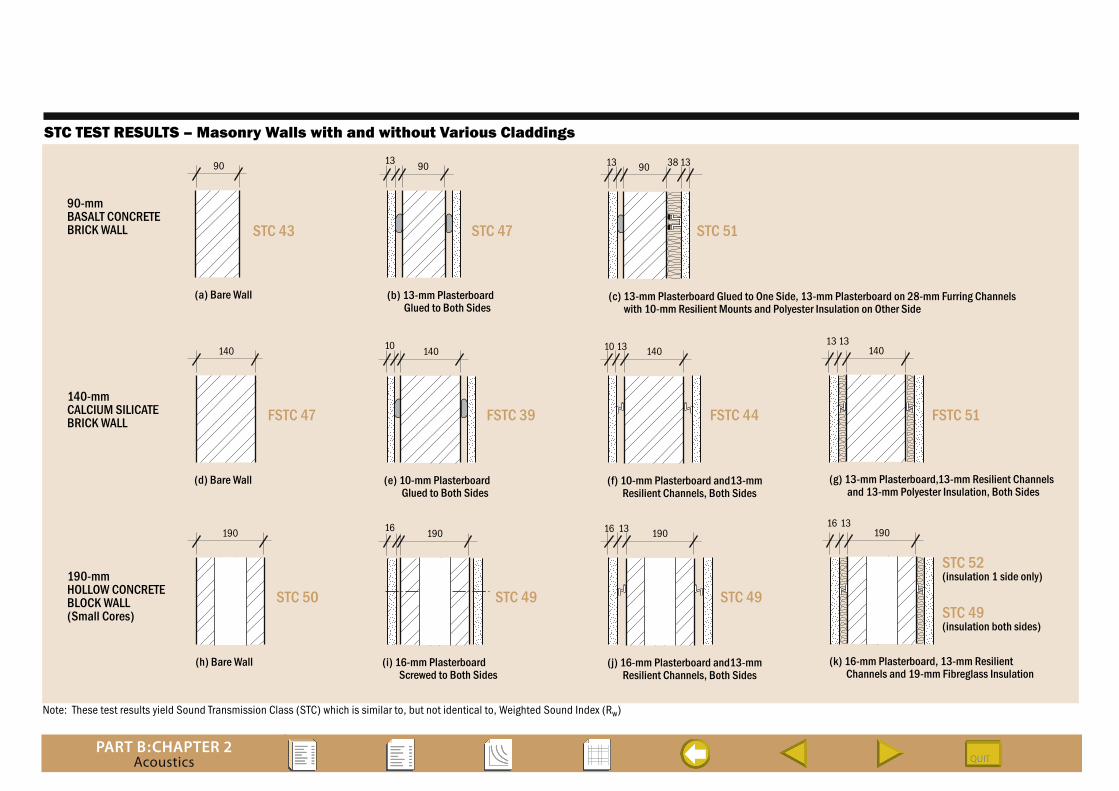
Note: These test results yield Sound Transmission Class (STC) which is similar to, but not identical to, Weighted Sound Index (Rw)
STC TEST RESULTS – Masonry Walls with and without Various Claddings
140
FSTC 47
(d) Bare Wall
14010 14010 13 14013 13
FSTC 39
(e) 10-mm Plasterboard Glued to Both Sides
FSTC 44
(f) 10-mm Plasterboard and13-mm Resilient Channels, Both Sides
FSTC 51
(g) 13-mm Plasterboard,13-mm Resilient Channels and 13-mm Polyester Insulation, Both Sides
140-mmCALCIUM SILICATEBRICK WALL
90
STC 43
(a) Bare Wall
9013 13 133890
STC 47
(b) 13-mm Plasterboard Glued to Both Sides
STC 51
(c) 13-mm Plasterboard Glued to One Side, 13-mm Plasterboard on 28-mm Furring Channels with 10-mm Resilient Mounts and Polyester Insulation on Other Side
90-mmBASALT CONCRETEBRICK WALL
190
STC 50
(h) Bare Wall
19016 19016 13 19016 13
STC 49
(i) 16-mm Plasterboard Screwed to Both Sides
STC 49
(j) 16-mm Plasterboard and13-mm Resilient Channels, Both Sides
STC 52(insulation 1 side only)
STC 49(insulation both sides)
(k) 16-mm Plasterboard, 13-mm Resilient Channels and 19-mm Fibreglass Insulation
190-mmHOLLOW CONCRETEBLOCK WALL(Small Cores)

PART B:CHAPTER 2Acoustics
Note: These test results yield Sound Transmission Class (STC) which is similar to, but not identical to, Weighted Sound Index (Rw)
STC TEST RESULTS – Bare Masonry Walls
Soun
d Tr
ansm
issi
on C
lass
(STC
)
Wall Surface Density (kg/m2)100 200 300 400 500
60595857565554535251504948474645444342414039383736353433323130
8, 19
14
15
1716
20, 4 1, 18 910
28 21126, 23, 24 25
5, 22
1329
3, 267, 30
2, 27
31
Datanumber
Unitthickness(mm)
Surfacedensity(kg/m2) Unit material Notes Test referenceSTC
1 2 3 4 5 6 7 8 9
10 11 12 13 14 15 16 17 18 19
20 21 22 23 24 25 26 27 28 29 30 31
90 140 140 110 110 150 200 110 110
110 110 150 200 90 90 90 110 90 110
110 110 110 140 140 140 140 140 190 190 190 190
425250424543493842
41164448313743424238
424445434343505244484956
EBS1044EBS1051EBS1192EBS238EBS257EBS287EBS407EBS449LCA 529-83
LCA 1122-88LCA 1287-90LCA 2192-1-75LCA 2192-3-75RTA T621-01F103RTA T621-01F120RTA T621F168RTA T621F171CMAA Internal ReportEBS No. 48 ref no. 7011-1
EBS No. 48 ref no. 6068-1EBS No. 48 ref no. 6078-1EBS No. 48 ref no. 6078-3EBS No. 48 ref no. 6017-1CMAA Internal ReportCMAA Internal ReportCMAA Internal ReportCMAA Internal ReportCMAA Internal ReportCMAA Internal ReportCMAA Internal ReportCMAA Internal Report
Basalt brickDense hollowDense hollowClinker brickDense brickDense hollowDense hollowLightweight concreteDense hollow
ScoriaBasalt/scoriaDense hollowScoriaScoriaScoriaScoria/basaltScoria lightweightDense brickConcrete
ConcreteConcreteConcreteClay BaggedDense hollow BaggedDense concreteDense hollowDense hollowLightweight concreteLightweight concrete Paint one sideDense concreteLightweight concrete Paint one side
174260253151195170214110208
190156170230130150140120174110
150175195170171210253260156156215435
DATA DETAILS

PART B:CHAPTER 2Acoustics
Note: These test results yield Sound Transmission Class (STC) which is similar to, but not identical to, Weighted Sound Index (Rw)
STC TEST RESULTS – Rendered Masonry Walls
Datanumber
Unitthickness(mm)
Surfacedensity(kg/m2) Unit material Render Test referenceSTC
1 2 3 4 5 6 7 8 9
10 11 12 13 14 15 16 17 18 19
20 21 22 23
90 90 110 110 110 150 110 114 90
190 90 90 90 90 90 110 110 110 110
140 140 150 190
494751485247504545
44424345474946484952
47475054
EBS1044EBS1044EBS1469EBS238EBS257EBS287LCA 1293-90LCA 2884-1-77RTA T621F126
RTA T621F138RTA T621F167RTA T621F179CMAA Internal ReportCMAA Internal ReportCMAA Internal ReportEBS No. 48 ref no. 7011-2EBS No. 48 ref no. 6068-2EBS No. 48 ref no. 7112-01EBS No. 48 ref no. 6078-4
CMAA Internal ReportEBS No. 48 ref no. 6017-2EBS No. 48 ref no. 7063EBS No. 48 ref no. 6079
Basalt brickBasalt brickDense hollowClinker brickDense brickDense hollowBasalt/scoriaBoral concreteScoria
ScoriaScoria lightweightScoria lightweightDense hollowDense brickDense brickConcrete brickConcrete brickConcrete brickConcrete brick
Dense concrete hollowDense concrete hollowWoodwaste & cement, hollowDense concrete
13-mm, 2 faces13-mm, 1 face13-mm, 2 faces13-mm, 2 faces13-mm, 2 faces13-mm, 2 faces13-mm, 2 faces13-mm, 2 faces13-mm, 2 faces
13-mm, 2 faces13-mm, 2 faces13-mm, 2 faces13-mm, 2 faces13-mm, 1 face13-mm, 2 faces13-mm, 2 faces13-mm, 2 faces13-mm, 2 faces13-mm, 2 faces
13-mm, 2 faces13-mm, 2 faces13-mm, 2 faces13-mm, 2 faces
224.0 199.0 258.0 205.0 249.0 215.0 192.4
198.0 139.0
209.0 190.0 145.0 208.0 199.0 224.0 160.0 205.0 230.0 250.0
215.0 215.0 295.0 265.0
DATA DETAILS
Soun
d Tr
ansm
issi
on C
lass
(STC
)
Wall Surface Density (kg/m2)100 200 300 400 500
60595857565554535251504948474645444342414039383736353433323130
1112
916
108
2, 144, 17
1, 157 22
35, 19
23
18
6, 20, 21
13
PART B:CHAPTER 2Acoustics
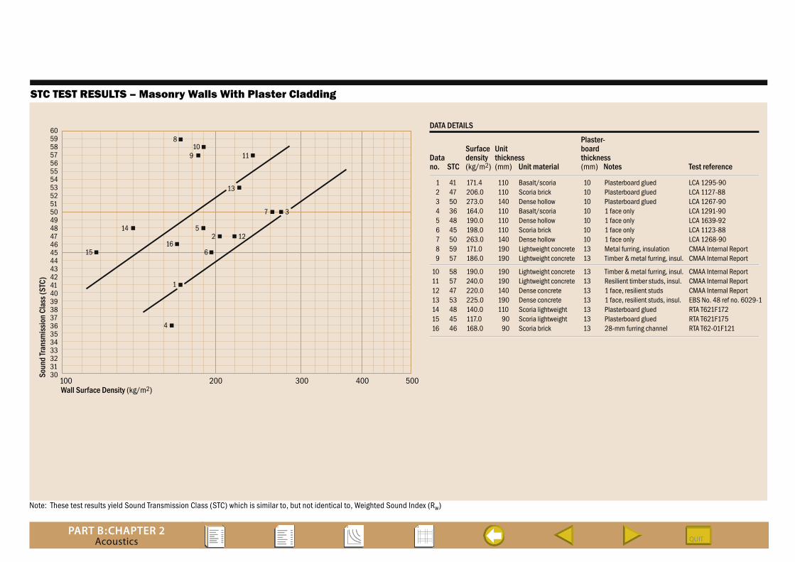
Note: These test results yield Sound Transmission Class (STC) which is similar to, but not identical to, Weighted Sound Index (Rw)
STC TEST RESULTS – Masonry Walls With Plaster Cladding
Datano.
Unitthickness(mm)
Surfacedensity(kg/m2) Unit material
Plaster-boardthickness(mm) Test referenceSTC
1 2 3 4 5 6 7 8 9
10 11 12 13 14 15 16
110 110 140 110 110 110 140 190 190
190 190 140 190 110 90 90
414750364845505957
58574753484546
LCA 1295-90LCA 1127-88LCA 1267-90LCA 1291-90LCA 1639-92LCA 1123-88LCA 1268-90CMAA Internal ReportCMAA Internal Report
CMAA Internal ReportCMAA Internal ReportCMAA Internal ReportEBS No. 48 ref no. 6029-1RTA T621F172RTA T621F175RTA T62-01F121
Basalt/scoriaScoria brickDense hollowBasalt/scoriaDense hollowScoria brickDense hollowLightweight concreteLightweight concrete
Lightweight concreteLightweight concreteDense concreteDense concreteScoria lightweightScoria lightweightScoria brick
101010101010101313
13131313131313
Notes
Plasterboard gluedPlasterboard gluedPlasterboard glued1 face only1 face only1 face only1 face onlyMetal furring, insulationTimber & metal furring, insul.
Timber & metal furring, insul.Resilient timber studs, insul.1 face, resilient studs1 face, resilient studs, insul.Plasterboard gluedPlasterboard glued28-mm furring channel
171.4206.0273.0164.0190.0198.0263.0171.0186.0
190.0240.0220.0225.0140.0117.0168.0
DATA DETAILS
Soun
d Tr
ansm
issi
on C
lass
(STC
)
Wall Surface Density (kg/m2)100 200 300 400 500
60595857565554535251504948474645444342414039383736353433323130
4
1
61516
2514
7 3
13
11910
8
12
PART B:CHAPTER 2Acoustics
2.4 woRked exAmPle
Living
Living Living
Corri
dor
Corri
dor
LivingUNIT 1
UNIT 2
B
UNIT 3
UNIT 3 UNIT 4
UNIT 4
Bed Bed
Living Bed Bed
Level 1
Level 2
Level 3
Dining Hall
Bath
Bath
Kitchen
SECTION A-A
PLAN LEVEL THREE
A A
B
A
A
A
C
C
C
A
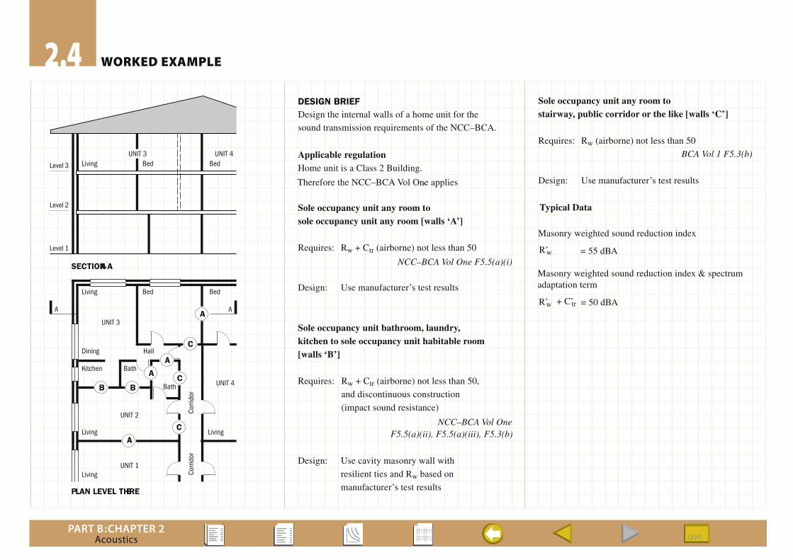
DESIGN BRIEFDesign the internal walls of a home unit for the
sound transmission requirements of the NCC–BCA.
Applicable regulationHome unit is a Class 2 Building.
Therefore the NCC–BCA Vol One applies .
Sole occupancy unit any room tosole occupancy unit any room [walls ‘A’]
Requires: Rw + Ctr (airborne) not less than 50
NCC–BCA Vol One F5.5(a)(i)
Design: Use manufacturer’s test results
Sole occupancy unit bathroom, laundry,kitchen to sole occupancy unit habitable room[walls ‘B’]
Requires: Rw + Ctr (airborne) not less than 50,
and discontinuous construction
(impact sound resistance)
F5.5(a)(ii). F5.5(a)(iii), F5.3(b)
Design: Use cavity masonry wall with
resilient ties and Rw based on
manufacturer’s test results
Sole occupancy unit any room tostairway, public corridor or the like [walls ‘C’]
Requires: Rw (airborne) not less than 50
BCA Vol 1 F5.3(b)
Design: Use manufacturer’s test results
NCC–BCA Vol One
Typical Data
Masonry weighted sound reduction index
R’w
R’w
Masonry weighted sound reduction index & spectrumadaptation term
+ C’tr
= 55 dBA
= 50 dBA