P2 Installation Depth - PNR Dynamic · Pop-A-Plug® II (P2) NEAR END ... expand outward. ... The P2...
40
EXPANSION SEAL TECHNOLOGIES DC8042 06/97 PAGE 1 OF 1 P2 Installation Depth (TECH TIP REPRINTED FROM EST ENERGY NEWS Volume 2, Issue 7 May/June, 1997) We have always stressed the importance of installing P2 Pop-A-Plugs at least an inch and three quarters deep. This prevents mechanical interference with the pin. It also eliminates any turbulence that might be caused by the pin projecting into the flow stream. I recently had an experience where the customer was following this practice to the letter, and it caused a problem. The customer reported that the plugs were “pulling through”, an indication that the plugs were too small. When the problem was reported, Paul Reiter, our local representative was on site within a few hours. His investigation revealed that the customer was installing the plugs 1-3/4” deep; however this time they were plugging an oil cooler. The tubesheet was only one inch thick. When the plug was repositioned in the tubesheet, the plugs installed correctly and the rest of the tubes were plugged uneventfully. So remember, install P2’s 1-3/4” deep wherever possible, but always in the tubesheet. ……......Ted Brooks, Area Sales Manager QUESTIONS? Contact EST Customer Service at any of the following locations with questions. In USA and Canada: tel: 800-355-7044, fax: 215-721-1101, e-mail: [email protected] In Europe: tel: +31-172-418841, fax: +31-172-418849; e-mail: [email protected] In Asia: tel: +65-6745-8560, fax: +65-6742-8700, e-mail: [email protected] On the Internet: www.expansionseal.com Expansion Seal Technologies is part of the EST Group of companies. EST Group provides a complete range of repair products, services and replacement parts covering the life cycle of tubular heat exchangers and condensers; additionally EST provides products and services to facilitate pressure testing pipe, piping systems, pressure vessels and their components. Visit EST Group on the internet at www.estgrp.com.
Transcript of P2 Installation Depth - PNR Dynamic · Pop-A-Plug® II (P2) NEAR END ... expand outward. ... The P2...

EXPANSION SEAL TECHNOLOGIES DC8042 06/97 PAGE 1 OF 1
P2 Installation Depth
(TECH TIP REPRINTED FROM EST ENERGY NEWS Volume 2, Issue 7 May/June, 1997) We have always stressed the importance of installing P2 Pop-A-Plugs at least an inch and three quarters deep. This prevents mechanical interference with the pin. It also eliminates any turbulence that might be caused by the pin projecting into the flow stream. I recently had an experience where the customer was following this practice to the letter, and it caused a problem. The customer reported that the plugs were “pulling through”, an indication that the plugs were too small. When the problem was reported, Paul Reiter, our local representative was on site within a few hours. His investigation revealed that the customer was installing the plugs 1-3/4” deep; however this time they were plugging an oil cooler. The tubesheet was only one inch thick. When the plug was repositioned in the tubesheet, the plugs installed correctly and the rest of the tubes were plugged uneventfully. So remember, install P2’s 1-3/4” deep wherever possible, but always in the tubesheet. ……......Ted Brooks, Area Sales Manager QUESTIONS? Contact EST Customer Service at any of the following locations with questions.
In USA and Canada: tel: 800-355-7044, fax: 215-721-1101, e-mail: [email protected] In Europe: tel: +31-172-418841, fax: +31-172-418849; e-mail: [email protected] In Asia: tel: +65-6745-8560, fax: +65-6742-8700, e-mail: [email protected] On the Internet: www.expansionseal.com
Expansion Seal Technologies is part of the EST Group of companies. EST Group provides a complete range of repair products, services and replacement parts covering the life cycle of tubular heat exchangers and condensers; additionally EST provides products and services to facilitate pressure testing pipe, piping systems, pressure vessels and their components. Visit EST Group on the internet at www.estgrp.com.


DC4000 10/94 Rev 6 03/06
Page 1 of 15 Pop-A-Plug® II (P2) NEAR END PLUGGING PROCEDURE
WARNING
• The user must read and thoroughly understand these installation instructions before any work begins. The user should also watch the P2 Installation & Training Video to learn how to handle and properly use the equipment. It is the responsibility of the user to establish appropriate safety, health and training measures for their personnel using, servicing or working in an area where this equipment is being used.
• The user must be a qualified operator familiar with correct operation, maintenance and use of hydraulic tools. Lack of knowledge in any of these areas can lead to personal injury.
• Trapped pressure in plugged or sealed tubes may cause tapered tube plugs or other plug types to be explosively ejected from the tube during maintenance work. Protective shielding or similar equipment must be in-place to protect users and others working in the area of the heat exchanger.
• Wear proper eye protection to protect against ejected parts or other projectiles. A face shield is recommended.
• Wear proper ear protection to protect against hearing loss or damage. • Although vibration of the hydraulic ram is minimal during operation, work
gloves are recommended to protect hands during operation. • Possible Kickback and Parts Ejection Hazard. Keep body, head, face and all
extremities clear from rear of hydraulic ram during operation. • Tools and components listed in this instruction are designed for the sole
purpose of installing P2 heat exchanger tube plugs. The equipment is not designed or intended to be used for other tasks.
• Power tools are not generally suited for coming in contact with electrical power sources. • Power tools shall not be used in an explosive atmosphere unless specifically designed for that purpose. • Unexpected tool movement or breakage of inserted tool could cause injury to personnel. • Unsuitable postures may not allow for proper counteracting of normal or unexpected movement of the tool
during operation. • Inspect equipment before each use to prevent unsafe conditions from developing. Do not use equipment if it is
damaged, altered or in poor condition. • These instructions are intended for the end-user or operator of this equipment. For additional information or
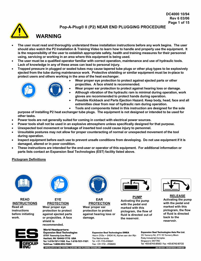
parts lists contact an Expansion Seal Technologies (EST) facility listed above. Pictogram Definitions
READ INSTRUCTIONS Read all instructions before initiating work.
RELEASE Activating the pump with the pedal end marked with this pictogram, the flow of fluid is directed back to the reservoir.
EAR PROTECTION
Wear proper ear protection to protect against hearing loss or damage.
EYE PROTECTION
Wear proper eye protection to protect against ejected parts or projectiles. A face shield is recommended.
PUMP Activating the pump with the pedal end marked with this pictogram, the flow of fluid is directed out of the reservoir.

EXPANSION SEAL TECHNOLOGIES DC4000 10/94 Rev 6 03/06
Page 2 of 15 HOW THE SYSTEM WORKS The Near End Plugging Procedure is to be followed for all plugging applications in U-Tube heat exchangers and in straight tube heat exchangers where the operator has access to both ends of the tube. P2 is to be installed only into tubes that have been expanded into the tubesheet by rolling or other methods. The heat exchanger tube to be plugged must be prepared and gauged for size by following the tube preparation procedures given in this instruction.
UNDERCUT SECTION
WHERE FRACTURE OCCURS
PIN BREAKAWAY
RING The P2 consists of a tapered pin, an internally and externally serrated ring and a breakaway. The plug is threaded onto a Pull Rod Assembly. The assembly is then inserted into the Hydraulic Ram. The plug is then ready to be recessed into the end of the faulty tube to be plugged. During installation, the tapered pin is pulled through the ring, causing it to expand outward. The ring expands until it makes contact with the ID of the tube. The tube ID restricts the expansion of the ring, causing an increased force on the Breakaway. When the proper installation force is achieved, the Breakaway pops and the installed plug is separated from the installation equipment. The P2 material must be closely matched to the tube and/or tubesheet material to minimize effects of thermal expansion and galvanic corrosion over the service life of the heat exchanger. Each plug is stamped with the plug size, in inches, rounded to three decimal places, and a single letter material designation. The plug size corresponds to the actual OD of the ring portion of the plug. The common material designations are as follows: (S) 316 Stainless Steel (N) Copper/Nickel (B) Brass (M) Monel (C) Carbon Steel P2 PLUG SIZING Prior to beginning any tube plugging, it is necessary to determine the size or sizes of P2's that will be required. The procedures given below have been used with success in estimating the proper P2 size(s) for the tubes to be plugged. The correct sized P2 must fit into the tube and be no more than .020" (.5 mm) smaller that the actual tube ID in the position where the plug will be installed. P2's are readily available in .020" (.5 mm) increments from .400" to 2.000" (10.16 mm to 50.8 mm). Sizes from .400” to .960” (10.2 mm TO 24.4 mm) and are generally in stock in each of the (5) standard materials listed above. For larger sizes and alternate materials contact EST Although these estimating procedures will aid in plug sizing for the majority of applications, occasionally the actual ID's will differ substantially from the calculated value due to tube end erosion or similar effects. If you find that the actual tube ID's differ from the estimated ID's, measurements of the actual tubes must be taken. Taking measurements of the actual tubes is the best method to determine the exact tube ID's. We recommend taking measurements in all cases where it is possible. 1. Tube ID Measurement (if not access to heat exchanger is not possible proceed to Step 2). Make and record a horizontal and vertical measurement of each tube ID at a depth where the plug will be installed. A snap bore gage or ID micrometer is recommended for these measurements. The plug should be positioned at an installation depth of 1-3/4” (44.5 mm) (minimum as long as the expanded length (e.g. roller expanded) of the tube and tubesheet thickness is greater than 1-3/4” (44.5 mm). If the expanded length of tube or tubesheet thickness is less than 1-3/4” (44.5 mm) the installation depth for the plug needs to be reduced accordingly.
Alternate Go/No-Go Gauging: Contact EST for a Go/No-Go Gage to aid in determining the correct P2 size. The use of the Go/No-Go Gage will require that any weld droop protruding into the tube ID is removed.
GO NO GO
EXPANSION SEAL TECHNOLOGIES DC4000 10/94 Rev 6 03/06
Page 3 of 15 Heat Exchangers manufactured with a soft roll close to the face of the tubesheet will give a false Go/No-Go gage reading and plugs will be undersized and subject to failure. The soft roll must be brushed out to achieve uniform tube ID and true Go/No-Go gage reading. 2. Calculated Tube ID Consult the Heat Exchanger Data Sheet supplied by the heat exchanger manufacturer to determine the tube OD and wall thickness. From the data sheet it is also necessary to determine if the tubes have been rolled or expanded by a similar method. 3. P2 Sizing For rolled or expanded tubes consult Table 1 for the proper P2 sizes.
If the tubes have not been roller expanded or if the heat exchanger has inlet tube shields or coated tube ID's, call EST for assistance in determining the proper method and correct sizes of P2. NOTE: This sizing procedure is only a starting point! Our experience has shown that the actual ID of the tubes can be significantly larger than estimated. Size variations can be caused by over rolling, corrosion or erosion. Differences as high as .090" (2.3 mm) between the inlet and outlet tube ID's are occasionally encountered. If the tubes cannot be measured prior to ordering P2’s, it is recommended that in addition to the recommended P2 size, the next larger consecutive size be ordered to have on hand. Unused sizes between P2-400 and P2-960 in our 5 stock materials can be returned or exchanged if they are unopened. Tube Sizing Example Select the correct P2 for a 3/4" (19.1 mm) x 12 B.W.G. rolled tube. According to Table 1, the ID of the rolled tube is .554" (14.1 mm). The chart specifies a P2-540. However, allowing for possible tube end erosion and/or over rolling, the actual tube ID may be closer to .560" (14.2 mm). Knowing that brushing the tube ID with the tube preparation brush will enlarge the tube ID, it is recommended that P2-560 also be on hand. 4. Equipment Required
In addition to the proper size and material of P2's, it is important that the proper installation equipment also be on hand. Existing obstructions such as channel heads and hemispherical heads can limit accessibility to perimeter tubes. The use of installation equipment designed for these conditions is the only way to ensure proper installation of the P2.
Below is a list showing the minimum equipment that should be on hand prior to beginning any plugging. Refer to Tables 1 & 2 for part numbers of listed equipment.
1. P2 kits of proper size(s) Kit includes: (10) P2 tube plugs (1) Tube preparation brush. (1) Go/No-Go Gage to verify plug sizing 2. Hydraulic Ram with safety cable for installation 3. (1) Pull Rod Assembly (Standard or Channel Head as required). The pull rod assemblies are matched to the size of the P2's. 4. (1) Spare Plug Positioner. 5. Electric or air powered drill, for tube brushing. 6. For rolled and welded tubes, a tapered reamer to remove weld droop For Perimeter Tubes Frequently the tubes that require plugging are on the perimeter of the tubesheet. Hemispherical heads often present clearance problems making it difficult or impossible to use the standard Ram. For these applications, EST can supply a special Close Quarters Ram, Model CQR-1000. Contact EST for additional information. 5. Technical Assistance
If any part of the plug sizing procedure or equipment required is not clear, please contact EST with the following information: • Tube size and Wall Thickness
EXPANSION SEAL TECHNOLOGIES DC4000 10/94 Rev 6 03/06
Page 4 of 15 • Operating Pressure and Temperature • Tube and Tubesheet Material • Tube Joint Type (Rolled/Welded) • Existing Obstructions (Channel Head, etc.).
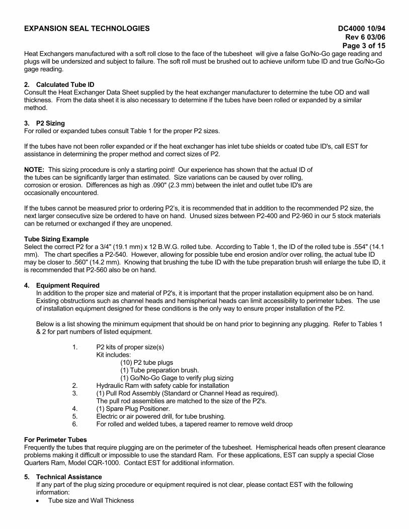
TUBE PREPARATION AND SIZE VERIFICATION 6. Remove weld droop REMOVE WELD
PROTRUDING INTO TUBE ID
If tube is welded to sheet, remove weld droop with a TAPERED REAMER. Removing weld droop is a fairly quick step and should only take 15-30 seconds. Only remove the weld (burr) projecting into the tube ID. Use a tapered reamer not a straight reamer. Size the reamer so that the small end of the taper fits into the tube and the large end does not. The reamer should be operated in the following manner: • Install tapered reamer in a variable speed drill and lightly lubricate reamer
with cutting oil. • Keep reamer axis parallel to tube axis. • Use an on/off method. Lightly squeeze the trigger on the drill to a low rpm and then release. • Use very slight forward pressure when pushing the reamer into the tube end. Too much pressure may cause the reamer to catch. • Let the reamer do the work. Never force the reamer into the tube end.
WARNING Failure to remove weld droop will cause Go/No Go gage to give a false reading. This false Go/ No Go gage reading will direct user to install an UNDERSIZED PLUG which will leak either initially or later.
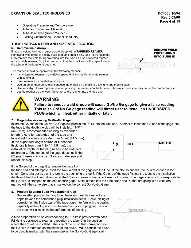
7. Gage tube size using Go/No-Go Gage Insert the Go end of the Go/No-Go Gage supplied in the P2 kit into the tube end. Attempt to insert the Go end of the gage into the tube to the depth the plug will be installed. (1-3/4” (44.5 mm) is recommended as long as expanded length (e.g. roller expanded) of the tube and tubesheet thickness is greater than 1-3/4” (44.5 mm). If the expanded length of tube or tubesheet thickness is less than 1-3/4” (44.5 mm), the installation depth for the plug needs to be reduced accordingly. If the go end of the gage does not fit, the P2 size chosen is too large. Go to a smaller size and repeat this step. If the Go end of the gage fits, remove the gage from the tube end and attempt to insert the No-Go end of the gage into the tube. If the No-Go end fits, the P2 size chosen is too small. Go to a larger size and return to the beginning of step 6. If the Go end of the gage fits into the tube, to the installation depth and the No-Go end does not fit, the P2 size chosen is the correct size for this tube. The gage size, which corresponds to the P2 size, is stamped on the end of each gage. Make certain that the tube brush and P2 that are going to be used are marked with the same size that is marked on the correct Go/No-Go Gage.
GO NO GOX
8. Prepare ID using Tube Preparation Brush
Before attempting to plug any tube, the tubes must be cleaned to a depth beyond the established plug installation depth. Scale, pitting or corrosion on the inside wall of the tube could interfere with the sealing capability of the plug and must be removed prior to plugging. Use of the brush will also aid in the performance of the plug.
A tube preparation brush corresponding to P2 size is provided with each P2 kit. It is designed to clean and roughen the tube ID in the position where the P2 will be installed. The size of the brush that corresponds to the P2 size is stamped on the shank of the brush. Make certain the brush to be used is marked with the same size as the Go/No-Go Gage used in
EXPANSION SEAL TECHNOLOGIES DC4000 10/94 Rev 6 03/06
Page 5 of 15 step 7. Attach the tube preparation brush to an electric or air powered drill that is capable of approximately 300 to 500 RPM. Use the tube brush marked with the same size as the Go/No Go gage that fits after removing weld droop. Operate the brush with a power drill for at least 30 seconds (5 seconds for 90/10 Cu/Ni and Brass tubes) back and forth from the tube opening to the installation depth evenly to prevent a tapered condition. If as a result of uneven brushing the tube entrance is smaller, the installed plug may be undersized and leak. Do not use an oversized brush, force the brush into the tube, or bend the stem. These actions will break the stem and cause deep grooves in the tube. Do not reverse drill because bristles will fall out. A Brush lubricant / Spark inhibitor Lube-A-Tube is available from EST, if required. Lube-A-Tube should be used when brushing stainless steel tubes or brush may wear out quickly. NOTE: Each P2 kit includes a tube preparation brush. After 10 tubes have been prepared discard the brush and obtain a fresh brush. Brush using clockwise motion only or brush may lose bristles. 9. Inspect tube ID for defects Remove any loose particle or material from the tube ID and carefully inspect tube for scale, pitting or other defects. These conditions must be corrected for plug to seal properly. A properly brushed tube should have a shiny metallic finish. Deeply pitted tubes may require the use of larger preparation brushes and plugs.
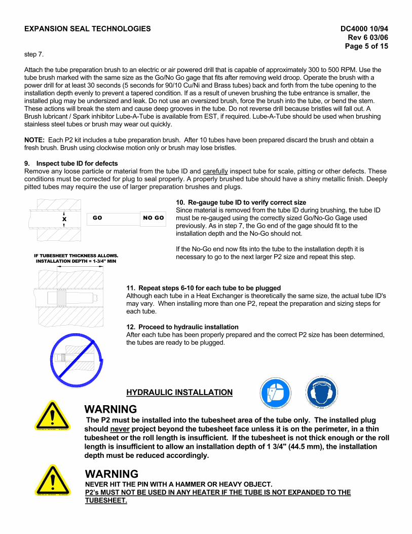
10. Re-gauge tube ID to verify correct size Since material is removed from the tube ID during brushing, the tube ID must be re-gauged using the correctly sized Go/No-Go Gage used previously. As in step 7, the Go end of the gage should fit to the installation depth and the No-Go should not. If the No-Go end now fits into the tube to the installation depth it is necessary to go to the next larger P2 size and repeat this step.
11. Repeat steps 6-10 for each tube to be plugged Although each tube in a Heat Exchanger is theoretically the same size, the actual tube ID's may vary. When installing more than one P2, repeat the preparation and sizing steps for each tube. 12. Proceed to hydraulic installation After each tube has been properly prepared and the correct P2 size has been determined, the tubes are ready to be plugged.
HYDRAULIC INSTALLATION
mIF TUBESHEET THICKNESS ALLOWS.INSTALLATION DEPTH = 1-3/4" MIN
NO GOGOX
WARNING The P2 must be installed into the tubesheet area of the tube oshould never project beyond the tubesheet face unless it is ontubesheet or the roll length is insufficient. If the tubesheet is nlength is insufficient to allow an installation depth of 1 3/4" (44depth must be reduced accordingly.
WARNING NEVER HIT THE PIN WITH A HAMMER OR HEAVY OBJECT. P2’s MUST NOT BE USED IN ANY HEATER IF THE TUBE IS NOT EXTUBESHEET.
nly. The installed plug the perimeter, in a thin ot thick enough or the roll .5 mm), the installation
PANDED TO THE
EXPANSION SEAL TECHNOLOGIES DC4000 10/94 Rev 6 03/06
Page 6 of 15
WARNING
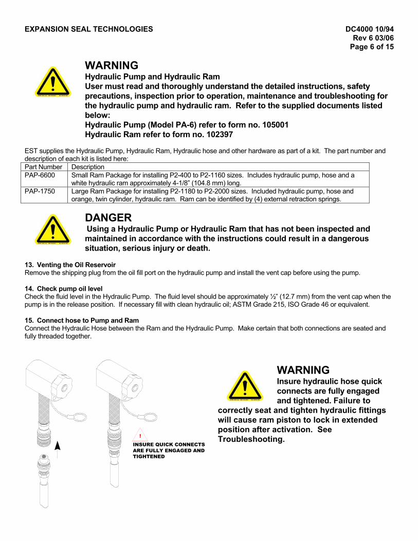
Hydraulic Pump and Hydraulic Ram User must read and thoroughly understand the detailed instructions, safety precautions, inspection prior to operation, maintenance and troubleshooting for the hydraulic pump and hydraulic ram. Refer to the supplied documents listed below: Hydraulic Pump (Model PA-6) refer to form no. 105001 Hydraulic Ram refer to form no. 102397
EST supplies the Hydraulic Pump, Hydraulic Ram, Hydraulic hose and other hardware as part of a kit. The part number and description of each kit is listed here: Part Number Description PAP-6600 Small Ram Package for installing P2-400 to P2-1160 sizes. Includes hydraulic pump, hose and a
white hydraulic ram approximately 4-1/8” (104.8 mm) long. PAP-1750 Large Ram Package for installing P2-1180 to P2-2000 sizes. Included hydraulic pump, hose and
orange, twin cylinder, hydraulic ram. Ram can be identified by (4) external retraction springs.
DANGER
1R 1Cp 1Cf
Using a Hydraulic Pump or Hydraulic Ram that has not been inspected and maintained in accordance with the instructions could result in a dangerous situation, serious injury or death.
3. Venting the Oil Reservoir emove the shipping plug from the oil fill port on the hydraulic pump and install the vent cap before using the pump.
4. Check pump oil level heck the fluid level in the Hydraulic Pump. The fluid level should be approximately ½” (12.7 mm) from the vent cap when the ump is in the release position. If necessary fill with clean hydraulic oil; ASTM Grade 215, ISO Grade 46 or equivalent.
5. Connect hose to Pump and Ram onnect the Hydraulic Hose between the Ram and the Hydraulic Pump. Make certain that both connections are seated and
ully threaded together.
TIGHTENEDARE FULLY ENGAGED ANDINSURE QUICK CONNECTS
WARNING
!
Insure hydraulic hose quick connects are fully engaged and tightened. Failure to
correctly seat and tighten hydraulic fittings will cause ram piston to lock in extended position after activation. See Troubleshooting.

EXPANSION SEAL TECHNOLOGIES DC4000 10/94 Rev 6 03/06
Page 7 of 15 16. Connect air supply Remove the thread protector from the air inlet of the pump. Select and install the threaded fittings that are compatible with your air supply fittings. An in-line filter/lubricator should be installed close to the pump. Add a few drops of hydraulic oil, ASTM Grade 215, ISO Grade 46 or equivalent, to air intake weekly if no lubricator is used or when pump will be idle for a long time. A clean, dry and lightly lubricated air supply will insure long pump life. The air supply should be 20 CFM (.57M3/min.) and approximately 100 psi (7 Bar) at the pump. Air pressure should be regulated to a maximum of 140 psi (9 Bar). Connect the air supply fitting to the Hydraulic Pump.
AIR SUPPLYCONNECT
HERESTEP
STROKESPISTON
FRONT
17. Test Ram/Pump set-up To verify Ram/Pump set-up, step on the end of the pump pedal marked "PUMP" while watching the Hydraulic Ram. Within a few seconds, the Ram should begin to stroke. Note that the piston strokes out of the back of the hydraulic Ram. If the Ram does not stroke, check all connections, the oil level and repeat this step.
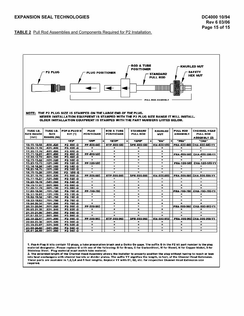
18. Obtain Pull Rod Assembly Based on the plug size being installed, obtain the appropriate Pull Rod Assembly. NOTE: The Standard Pull Rod Assembly consists of the following: a. Pull Rod -female thread in one end, male thread on the other end. b. Plug Positioner. c. Rod & Tube Positioner. d. Knurled Nut which threads on to the male end of the Pull Rod after it is inserted into the Ram. The Channel Head Pull Rod consists of the above parts and: e. Stand-off ring. f. Compression Tube which fits over the Pull Rod. 19. Check Pull Rod Assembly Verify that the Pull Rod Assembly is assembled correctly. The directional arrows stamped on
both the Rod and Tube Positioner and the Plug Positioner should always point towards the end of the Pull Rod where the plug will be attached.
STANDARDPULL ROD
PLUG POSITIONER
PULL ROD ASSEMBLY
ROD & TUBEPOSITIONER
KNURLED NUT
SAFETYHEX NUT
EXPANSION SEAL TECHNOLOGIES DC4000 10/94 Rev 6 03/06
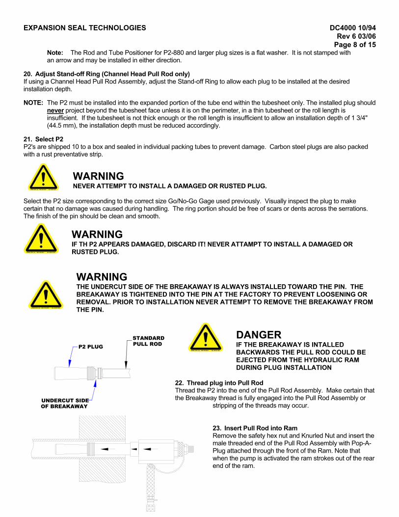
Page 8 of 15 Note: The Rod and Tube Positioner for P2-880 and larger plug sizes is a flat washer. It is not stamped with an arrow and may be installed in either direction.
20. Adjust Stand-off Ring (Channel Head Pull Rod only) If using a Channel Head Pull Rod Assembly, adjust the Stand-off Ring to allow each plug to be installed at the desired installation depth. NOTE: The P2 must be installed into the expanded portion of the tube end within the tubesheet only. The installed plug should
never project beyond the tubesheet face unless it is on the perimeter, in a thin tubesheet or the roll length is insufficient. If the tubesheet is not thick enough or the roll length is insufficient to allow an installation depth of 1 3/4" (44.5 mm), the installation depth must be reduced accordingly.
21. Select P2 P2's are shipped 10 to a box and sealed in individual packing tubes to prevent damage. Carbon steel plugs are also packed with a rust preventative strip.
WARNING NEVER ATTEMPT TO INSTALL A DAMAGED OR RUSTED PLUG.
Select the P2 size corresponding to the correct size Go/No-Go Gage used previously. Visually inspect the plug to make certain that no damage was caused during handling. The ring portion should be free of scars or dents across the serrations. The finish of the pin should be clean and smooth.
WARNING IF TH P2 APPEARS DAMAGED, DISCARD IT! NEVER ATTAMPT TO INSTALL A DAMAGED OR RUSTED PLUG.
WARNING
THE UNDERCUT SIDE OF THE BREAKAWAY IS ALWAYS INSTALLED TOWARD THE PIN. THE BREAKAWAY IS TIGHTENED INTO THE PIN AT THE FACTORY TO PREVENT LOOSENING OR REMOVAL. PRIOR TO INSTALLATION NEVER ATTEMPT TO REMOVE THE BREAKAWAY FROM THE PIN.DANGER
STANDARDPULL RODP2 PLUG
UNDERCUT SIDEOF BREAKAWAY
IF THE BREAKAWAY IS INTALLED BACKWARDS THE PULL ROD COULD BE EJECTED FROM THE HYDRAULIC RAM DURING PLUG INSTALLATION
22. Thread plug into Pull Rod Thread the P2 into the end of the Pull Rod Assembly. Make certain that the Breakaway thread is fully engaged into the Pull Rod Assembly or
stripping of the threads may occur. 23. Insert Pull Rod into Ram Remove the safety hex nut and Knurled Nut and insert the male threaded end of the Pull Rod Assembly with Pop-A-Plug attached through the front of the Ram. Note that when the pump is activated the ram strokes out of the rear end of the ram.

EXPANSION SEAL TECHNOLOGIES DC4000 10/94 Rev 6 03/06
Page 9 of 15 NOTE: Current Rams are stamped with a directional arrow. This arrow points toward the front of the Ram. Also this arrow
should point towards the P2 as do both arrows on the Rod & Tube and Plug Positioner. 24. Install Knurled Nut onto Pull Rod Thread the Knurled Nut onto the Pull Rod until it is tight against the large black nut on the back of the Hydraulic Ram. NOTE: The Knurled Nut used for P2-400 to P2-860 is stepped. The smaller diameter step should be installed towards the
ram. The step fits into the piston ID and centers the pull rod. The Knurled Nut used on larger P2 sizes is flat and can be installed in either direction.
After hand tightening the Knurled Nut there should be no "play" between the parts of the assembled Pull Rod. The Plug Positioner should be tight against the ring of the P2. The OD of the Plug Positioner should fit against the end surface of the ring. If the Plug Positioner OD is larger than the ring or the Positioner end does not fit against the end surface of the ring, the Plug Positioner selected is not the correct size or is installed backwards. Refer to Table 1 for part numbers. Obtain the correct parts and repeat this step. 25. Install Safety Cable Slip loop in Safety Cable over exposed threaded end of Pull Rod so it rests against the Knurled Nut. While holding the safety Cable in place thread the Safety Hex Nut onto the Pull Rod hand-tight.
Recess P2 into tube While holding the ram, insert the P2 into the tube and recess it to the installation depth. P2's must always be installed into the portion of the tube restrained by the tubesheet. NOTE: The desired installation depth is 1 3/4" (44.5 mm). This depth will
prevent the pin of the P2 from projecting beyond the face of the tubesheet after the plug is installed. If the thickness of the tubesheet or the expanded length of the tube does not permit a 1-3/4” (44.5 mm) installation depth, install the plug as deep as possible while keeping the plug positioned within the tubesheet.
DANGER POSSIBLE KICKBACK AND PARTS EJECTION HAZARD. KEEP BODY AND ALL EXTREMITIES CLEAR FROM REAR OF HYDRAULIC RAM DURING OPERATION. MAKE CERTAIN SAFETY CABLE IS
ENGAGED WITH PULL ROD ASSEMBLY PRIOR TO OPERATION.
WARNING NEVER OPERATE THE HYDRAULIC RAM IF THE P2 PLUG IS NOT WITHIN THE HEAT EXCHANGER TUBE.
IF TUBESHEET THICKNESS ALLOWS. INSTALLATION DEPTH = 1-3/4" MIN
INSTALLATION DEPTH
1-3/4" MIN

EXPANSION SEAL TECHNOLOGIES DC4000 10/94 Rev 6 03/06
Page 10 of 15
26. Activate Ram to install plug While guiding the Ram with hands to avoid cocking of the P2 plug, activate the Hydraulic Pump by stepping on the end of the
pedal marked "PUMP". Pressure will start to build within the ram and the piston will begin to stroke. Continue to operate the pump until the Pop-A-Plug "Pops" or the Ram is fully stroked and the pressure gauge on the pump reaches approximately 7500 psi (515 Bar).
WARNING
IF AFTER ONE FULL STROKE OF THE RAM, THE P2 PLUG HAS NOT CONTACTED THE TUBE ID, THE P2 SIZE IS TOO SMALL. REMOVE THE PLUG AND REPEAT THE SIZING PROCEDURE.
NOTE: The Hydraulic Ram used in the PAP-6600 Ram Package has a maximum stroke of 1" (25.4 mm). When the piston in
the Ram reaches the maximum stroke, the pressure shown on the gauge will dramatically increase. If P2 plug contacted the tube ID but the plug did not “POP”, a second stroke of the Hydraulic Ram is necessary. For the second stroke of the Hydraulic Ram: A. Continue to support the weight of the Ram.
B. Step on the end of the Hydraulic Pump marked "RELEASE". This will cause the piston in the Hydraulic Ram to retract.
C. Remove slack in the Pull Rod by hand tightening the Knurled Nut. After hand tightening the Knurled Nut there should be no "play" between the parts of the Pull Rod Assembly.
D. Step on the Pump pedal marked “PUMP” to re-stroke the Ram.
DANGER POSSIBLE KICKBACK AND PARTS EJECTION HAZARD. KEEP BODY AND ALL
EXTREMITIES CLEAR FROM REAR OF HYDRAULIC RAM DURING OPERATION. MAKE CERTAIN SAFETY CABLE IS ENGAGED WITH PULL ROD ASSEMBLY PRIOR TO OPERATION.NOTE: If the P2 does not "POP" on the second stroke of the Ram, or if the pressure gauge on the pump reaches
approximately 7500 psi (515 Bar) before the plug "POPS", or if the breakaway fractures on the side opposite the undercut STOP! THE PLUG IS TOO SMALL. THE PLUG MUST BE REMOVED EVEN IF IT PASSES AN AIR OR HYDRO TEST! Unthread the Pull Rod Assembly and Remove the plug using EST’s Plug Removal Tool. Repeat tube sizing and preparation procedure prior to installing new plug.
27. Plug is installed When the P2 has been installed, the Breakaway will fracture and the Pull Rod and Hydraulic Ram assembly will be separated from the installed plug. Although experience indicates that the breakaway stub left in the pin will not unthread during normal heat exchanger operating conditions, the best practice is to remove the breakaway stub after plug installation.
2
WR
WARNING If the breakaway stub is to be removed, care must be exercised not to hit or force the installed plug.
8. Release Pump pressure
hile holding the Ram handle step on end of the Pump Pedal marked "RELEASE". This will allow the piston of the am to retract.

EXPANSION SEAL TECHNOLOGIES DC4000 10/94 Rev 6 03/06
Page 11 of 15 29. Remove Knurled Nut Remove the Knurled Nut from the back of the Pull Rod. 30. Remove broken Breakaway section from Pull Rod If installing additional plugs, remove the Breakaway section remaining in the Pull Rod end and discard. If no further plugs are being installed leave the broken Breakaway section in the pull rod. This will keep the Pull Rod Assembly together. 31. Repeat steps 19-32 Repeat Steps 19 through 32 for the remaining tubes to be plugged. WHEN PLUGGING IS COMPLETED 32. Pressure Testing of Installed Plug After plug installation is complete it is common practice to perform a pressure test of the installed plug by introducing air or water to the shell side of the heat exchanger. Installed plugs can be evaluated for leak-tightness while under-pressure. Foaming or bubbling leak detectors will aid in evaluating plugs under air test.
WARNING • Extreme caution is necessary when performing a pressure test. It is the
responsibility of the user to establish appropriate safety, health and training measures for their personnel performing or working in an area where a pressure test is being conducted.
• Never stand in the potential path of an installed tube plug • Never attempt to force or adjust an installed tube plug.
NOTE: Small leakage or weeping during pressure test indicates small surface imperfections in the tube that are difficult to see. A large
leak indicates surface imperfection in the tube such as scarring from a drill used to remove a sleeve or tapered pin, that should have been seen in step 9. In either case, remove plug using EST removal tool and repeat procedure using next larger brush and plug size.
33. Replace knurled nut Replace the Knurled Nut on the threaded end of the Pull Rod. 34. Return Pull Rod to Tool Box Return the Pull Rod Assembly to its place in the toolbox, or to and appropriate storage location. 35. Return Ram to Tool Box Dissemble the Ram and return it to the toolbox. 36. Return unused P2's to box If any unused P2's have been removed from their storage tubes, return them to their storage tubes and then into the proper P2 box.

EXPANSION SEAL TECHNOLOGIES DC4000 10/94 Rev 6 03/06
Page 12 of 15 SHORT FORM INSTALLATION INSTRUCTIONS, DC4010 Included with each P2 kit is a one-page short form instruction sheet. The first side describes the installation procedure in pictorial form. The second side describes the part numbers for P2 and the appropriate installation Pull Rods. It is recommended that this sheet be kept with the plugs and be reviewed prior to any tube plugging. DEMONSTRATION/TRAINING VIDEO, DC4018 Included in each new Hydraulic Ram Package is a demonstration/training video of the P2 tube plugging procedures. This video is also available for your training library by contacting EST, or your EST Representative or distributor. TO RETURN ANY MATERIAL If it should become necessary to return any material, for any reason, contact EST for a RETURN MATERIAL AUHORIZATION NUMBER (RMA #). Material returned without an RMA # will delay corrective action, credits or returned shipments. Complete unused/unopened P2 kits from P2-400 to P2-960 in our 5 stock materials in quantities less than our normal inventory level may normally be returned. Returned materials may be subject to a restocking fee. QUESTIONS? Contact EST Customer Service at any of the following locations with questions.
In USA and Canada: tel: 800-355-7044, fax: 215-721-1101, e-mail: [email protected] In Europe: tel: +31-172-418841, fax: +31-172-418849; e-mail: [email protected] In Asia: tel: +65-6745-8560, fax: +65-6742-8700, e-mail: [email protected] On the Internet: www.expansionseal.com
Expansion Seal Technologies is part of the EST Group of companies. EST Group provides a complete range of repair products, services and replacement parts covering the life cycle of tubular heat exchangers and condensers; additionally EST provides products and services to facilitate pressure testing pipe, piping systems, pressure vessels and their components. Visit EST Group on the internet at www.estgrp.com.

EXPANSION SEAL TECHNOLOGIES DC4000 10/94 Rev 6 03/06
Page 13 of 15 Operator Troubleshooting Guide
FIGURE 1: SIGNS OF UNDERSIZED PLUG, A PLUG INSTALLED BEYOND THE TUBESHEET, OR A PLUG INSTALLED IN UNROLLED TUBE INSIDE TUBESHEET
TAPERED PIN
1). POSITIONER STICKS TO TAPERED PIN AND BECOMES BELLMOUTHED. 2). BREAK-A-WAY FRACTURES ON WRONG SIDE OF COLLAR ALLOWING PULL ROD TO COME FREE OF THE POSITIONER.
CORRECTIVE ACTION: REMOVE PLUG USING EST REMOVAL TOOL. DISCARD POSITIONER. VERIFY WELD DROOP HAS BEEN REMOVED, VERIFY PLUG SIZING, & CONFIRM THAT THE PLUG IS INSTALLED IN A ROLLED & TUBESHEET RETRAINED PART OF THE TUBE.
PULL RODPLUG POSITIONER
UNDERSIZED INSTALLED PLUG
Problem Cause Solution
• Imperfections such as pitting, gouges or scratches still exist within the tube ID after brushing.
1. Deep imperfections can exist for normal heat exchanger operation or maintenance work.
1. Continue brushing with tube preparation brush until little or no resistance is encountered. If imperfections still exist move up to the next P2 kit size and repeat tube preparation steps.
• Plug Positioner flares or becomes stuck on installed P2 plug.
• Breakaway fractures on side opposite the undercut. (Normally the Breakaway fractures at the undercut)
• P2 Plug does not “POP” after second stroke of hydraulic ram.
1. Undersized Plug (Refer to Figure 1) 2. The plug was installed beyond the
thickness of the tubesheet 3. Heat Exchanger tube is not expanded
(rolled or similar) into the tubesheet.
1. Gage or measure tube ID at location where plug will be installed. Refer to Table 1 for proper P2 sizing.
2. Refer to heat exchanger datasheet to determine tubesheet thickness. Install P2 plug within the tubesheet length.
3. Roller expand heat exchanger tube at plug installation depth otherwise contact EST for assistance.
• Go/No-Go Gage indicates proper P2 size, but problems related to an undersized plug occur.
1. Weld droop has not been removed. 2. Heat exchanger tube is only “soft
rolled” for a short distance and expanded additionally beyond the “soft roll “ length.
1. Remove weld droop using tapered reamer. 2. Using tube preparation brush, enlarge tube so that
entrance and “soft roll” area has same ID as at the plug installation depth.
• Hydraulic Ram is stuck in extended position and will not retract.
1. Mating quick connects between Ram and hose or between Hydraulic pump and hose are not fully engaged and tightened.
2. Piston within hydraulic ram has been
damaged
1. Using gripping pliers turn locking collar on female quick connect to further engage connection. Continue tightening until ram retracts.
2. Return ram to EST for repair.
• Stem of Tube Preparation Brush fractures
1. Brush size is too large 2. The brush was forced or advanced to
quickly
1. Gage tube using Go/No-Go gage and select corresponding brush size.
2. Slowly feed the brush into the tube if significant resistance is encountered.
• Bristles fall out of Tube Preparation Brush
1. The brush was run counter-clockwise in the drill.
1. Obtain a new brush and operate brush clockwise.
• Inadequate space to get plug into tube when using the standard hydraulic ram with pull rod assembly.
1. Use EST’s Close Quarter Ram for P2 installation.

EXPANSION SEAL TECHNOLOGIES DC4000 10/94 Rev 6 03/06
Page 14 of 15 TABLE 1 Tube ID and P2 Size for Expanded (Rolled or similar) Heat Exchanger Tubes
WALL TUBE OD
THICKNESS DECIMAL BWG 1/2”
(12.7 mm) 5/8”
(15.88 mm) 3/4”
(19.05 mm) 7/8”
(22.23 mm) 1”
(25.40 mm) 8 .165”
( 4.19 mm) ID .453”
(11.51 mm) .578
(14.68 mm) .703
(17.86 mm) PLUG P2-440 P2-580 P2-700 9 .148
(3.76 mm) ID .484
(12.29 mm) .609
(15.47 mm) .734
(18.64 mm) PLUG P2-480 P2-600 P2-720
10 .134 (3.40 mm)
ID .509 (12.93 mm)
.634 (16.10 mm)
.759 (19.28 mm)
PLUG P2-500 P2-620 P2-760 11 .120
(3.05 mm) ID .409
(10.39 mm) .534
(13.56 mm) .659
(16.74 mm) .784
(19.91 mm) PLUG P2-400 P2-520 P2-660 P2-780
12 .109 (2.77 mm)
ID .429 (10.90 mm)
.554 (14.07 mm)
.679 (17.25 mm)
.804 (20.42 mm)
PLUG P2-420 P2-540 P2-680 P2-800 13 .095
(2.41 mm) ID .454
(11.53 mm) .579
(14.71 mm) .704
(17.88 mm) .829
(21.06 mm) PLUG P2-440 P2-580 P2-700 P2-820
14 .083 (2.11 mm)
ID .476 (12.09 mm)
.601 (15.27 mm)
.726 (18.44 mm)
.851 (21.62 mm)
PLUG P2-480 P2-600 P2-720 P2-840 15 .072
(1.83 mm) ID .495
(12.57 mm) .620
(15.75 mm) .745
(18.92 mm) .870
(22.10 mm) PLUG P2-500 P2-620 P2-740 P2-860
16 .065 (1.65 mm)
ID .508 (12.90 mm)
.633 (16.08 mm)
.758 (19.25 mm)
.883 (22.43 mm)
PLUG P2-500 P2-620 P2-760 P2-880 17 .058
(1.47 mm) ID .521
(13.23 mm) .646
(16.41 mm) .771
(19.58 mm) .896
(22.76 mm) PLUG P2-520 P2-640 P2-760 P2-900
18 .049 (1.24 mm)
ID .412 (10.46 mm)
.537 (13.64 mm)
.662 (16.81 mm)
.787 (19.99 mm)
.912 (23.16 mm)
PLUG P2-400 P2-540 P2-660 P2-780 P2-900 19 .042
(1.07 mm) ID .424
(10.77 mm) .549
(13.94 mm) .674
(17.12 mm) .799
(20.29 mm) .924
(23.47 mm) PLUG P2-420 P2-540 P2-660 P2-800 P2-920
20 .035 (.89 mm)
ID .437 (11.10 mm)
.562 (14.27 mm)
.687 (17.45 mm)
.812 (20.62 mm)
.937 (23.80 mm)
PLUG P2-440 P2-560 P2-680 P2-800 P2-940 21 .032
(.81 mm) ID .442
(11.23 mm) .567
(14.40 mm) .692
(17.58 mm) .817
(20.75 mm) .942
(23.93 mm) PLUG P2-440 P2-560 P2-700 P2-820 P2-940
22 .028 (.71 mm)
ID .450 (11.43 mm)
.575 (14.61 mm)
.700 (17.78 mm)
.825 (20.96 mm)
.950 (24.13 mm)
PLUG P2-440 P2-580 P2-700 P2-820 P2-940 23 .025
(.64 mm) ID .455
(11.56 mm) .580
(14.73 mm) .705
(17.91 mm) .830
(21.08 mm) .955
(24.26 mm) PLUG P2-460 P2-580 P2-700 P2-820 P2-960
24 .022 (.56 mm)
ID .460 (11.68 mm)
.585 (14.86 mm)
.710 (18.03 mm)
.835 (21.21 mm)
.960 (24.38 mm)
PLUG P2-460 P2-580 P2-700 P2-840 P2-960 NOTES: 1. Heat exchanger tube ID’s often vary between inlet & outlet side. More than one P2 size may be required. 2. If there is no previous experience indicating the correct p2 size and the tube ID’s cannot be measured it is recommended to have (2)
consecutive P2 sizes on hand. EXAMPLE: A feedwater heater with ¾” x 14 BWG tubes is being plugged for the first time. EST recommends enough P2-600 plugs to seal every tube and approximately half that amount of P2-620.
EXPANSION SEAL TECHNOLOGIES DC4000 10/94 Rev 6 03/06
Page 15 of 15 TABLE 2 Pull Rod Assemblies and Components Required for P2 Installation.
EXPANSION SEAL TECHNOLOGIES DC4002 11/00 REV 2 06/07
PAGE 1 OF 1
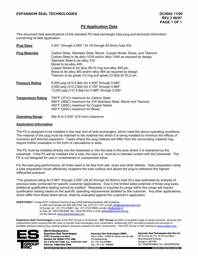
P2 Application Data This document lists specifications of the standard P2 heat exchanger tube plug and technical information concerning its field application. Plug Sizes 0.401” through 2.000” (10.18 through 50.8mm) tube IDs. Plug Materials Carbon Steel, Stainless Steel, Monel, Copper-Nickel, Brass, and Titanium. Carbon Steel to be alloy 1018 and/or alloy 1045 as required by design
Stainless Steel to be alloy 316. Monel to be alloy 405. Copper Nickel to be alloy 90/10 ring and alloy 405 pin.
Brass to be alloy 360 and/or alloy 464 as required by design. Titanium to be grade 1/2 ring and grade 23 (6AL4V ELI) pin
Pressure Rating 6,000 psig (413.6 Bar) for 0.400” through 0.680”. 4,500 psig (310.2 Bar) for 0.700” through 0.960”. *2,000 psig (137.8 Bar) for 0.980” through 2.000”. Temperature Rating 700°F (371C) maximum for Carbon Steel. 900°F (482C) maximum for 316 Stainless Steel, Monel and Titanium. 500°F (260C) maximum for Copper Nickel. 400°F (204C) maximum for Brass. Operating Range Slip fit to 0.020” (0.51mm) clearance. Application Information The P2 is designed to be installed in the near end of heat exchangers, which meet the above operating conditions. The material of the plug must be matched to the material into which it is being installed to minimize the effects of corrosion and thermal expansion. Cases where the plug material will differ from the surrounding material may require further evaluation in the form of calculations or tests. The P2 must be installed directly into the tubesheet or into the tube in the area where it is restrained by the tubesheet. If the P2 will be installed into a tube, the tube o.d. must be in intimate contact with the tubesheet. The P2 is not designed for use in unrestrained or unexpanded tubes. For the best plug performance, all holes need to be free from pits, scars and other defects. Hole preparation using a tube preparation brush effectively roughens the tube surface and allows the plug to withstand the highest differential pressure. *The pressure rating for 0.981” through 2.000” (24.92 through 50.80mm) tube ID’s was estimated by analysis of previous tests conducted for specific customer applications. Due to the limited sales potential of these plug sizes additional qualification testing cannot be justified. Requests or inquiries for plugs within this range will require qualification testing based on the specific operating requirements dictated by the customer. Any other applications, which differ from those listed above, shall be evaluated against the customer’s application. QUESTIONS? Contact EST Customer Service at any of the following locations with questions.
In USA and Canada: tel: 800-355-7044, fax: 215-721-1101, e-mail: [email protected] In Europe: tel: +31-172-418841, fax: +31-172-418849; e-mail: [email protected] In Asia: tel: +65-6745-8560, fax: +65-6742-8700, e-mail: [email protected] On the Internet: www.expansionseal.com
Expansion Seal Technologies is part of the EST Group of companies. EST Group provides a complete range of repair products, services and replacement parts covering the life cycle of tubular heat exchangers and condensers; additionally EST provides products and services to facilitate pressure testing pipe, piping systems, pressure vessels and their components. Visit EST Group on the internet at www.estgrp.com.
EXPANSION SEAL TECHNOLOGIES DC4010 9/94 REV 7 03/06
PAGE 1 OF 2 POP-A-PLUG® II (P2) INSTALLATION INSTRUCTIONS
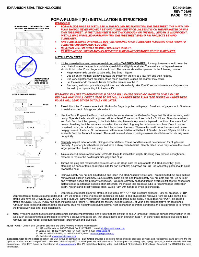
WARNINGS! • POP-A-PLUGS MUST BE INSTALLED IN THE ROLLED SECTION WITHIN THE TUBESHEET. THE INSTALLED
PLUG SHOULD NEVER PROJECT BEYOND TUBESHEET FACE UNLESS IT IS ON THE PERIMETER OR IN A THIN TUBESHEET. IF THE TUBESHEET IS NOT THICK ENOUGH OR THE ROLL LENGTH IS INSUFFICIENT, INSTALL RING IN ROLLED PORTION WITHIN THE TUBESHEET EVEN IF PIN PROJECTS BEYOND TUBESHEET.
NO GOGOX
IF TUBESHEET THICKNESS ALLOWS. INSTALLATION DEPTH = 1-3/4" MIN
STEP 1 (WELDED TUBES)
STEP 2 & 5
STEP 3
STEP 7
STEP 8
STEP 8
REMOVE WELDPROTRUDING INTO TUBE ID
• ANY TUBE SLEEVES OR SHIELDS MUST BE REMOVED FROM TUBESHEET PLUGGING AREA PRIOR TO TUBE PREPARATION AND PLUGGING.
• NEVER HIT THE PIN WITH A HAMMER OR HEAVY OBJECT. • P2 MUST NOT BE USED IN ANY HEATER IF THE TUBE IS NOT EXPANDED TO THE TUBESHEET. INSTALLATION STEPS 1. If tube is welded to sheet, remove weld droop with a TAPERED REAMER. A straight reamer should never be
used. Install tapered reamer in a variable speed drill and lightly lubricate. The small end of tapered reamer should fit into tube ID and large end should not. The reamer should be operated in the following manner: • Keep reamer axis parallel to tube axis. See Step 1 figure. • Use an on/off method. Lightly squeeze the trigger on the drill to a low rpm and then release. • Use very slight forward pressure. If too much pressure is used the reamer may catch. • Let the reamer do the work. Never force the reamer into the ID. • Removing weld droop is a fairly quick step and should only take 15 – 30 seconds to remove. Only remove
the weld (burr) projecting into the tube ID. WARNING! FAILURE TO REMOVE WELD DROOP WILL CAUSE GO/NO GO GAGE TO GIVE A FALSE READING WHICH WILL DIRECT USER TO INSTALL AN UNDERSIZED PLUG (SEE FIGURE A). UNDERSIZED PLUGS WILL LEAK EITHER INITIALLY OR LATER. 2. Take initial tube ID measurement with Go/No-Go Gage (supplied with plugs). Small end of gage should fit in tube
to installation depth & large end should not. 3. Use the Tube Preparation Brush marked with the same size as the Go/No Go Gage that fits after removing weld
droop. Operate the brush with a power drill for at least 30 seconds (5 seconds for Cu/Ni and Brass tubes) back and forth from the tube opening to the installation depth evenly to prevent a tapered condition. If as a result of uneven brushing the tube entrance is smaller, the installed plug may be undersized and leak. Do not use an oversized brush, force the brush into the tube, or bend the stem. These actions will break the stem and cause deep grooves in the tube. Do not reverse drill because bristles will fall out. A Brush Lubricant / Spark Inhibitor is available from the factory if required. This must be used when brushing stainless steel tubes or brush may wear out quickly.
4. Carefully inspect tube for scale, pitting or other defects. These conditions must be corrected for plug to seal
properly. A properly brushed tube should have a shiny metallic finish. Deeply pitted tubes may require the use of larger preparation brushes and plugs.
5. Take a second measurement with Go/No-Go Gage to installation depth. Brushing may remove enough tube
material to require the next larger size gage and plug. 6. Thread the plug that matches the correct Go/No-Go Gage onto the appropriate Pull Rod assembly. (See
stamping on parts or table on reverse side for part numbers) All arrows on Pull Rod Assembly parts should point toward the plug.
7. Remove safety hex nut and knurled nut and insert Pull Rod Assembly into Ram. Thread knurled nut onto pull rod
removing all slack in assembly. Secure safety cable on rod and thread safety hex nut onto pull rod. Be sure air and hydraulic hoses are properly connected. Failure to correctly seat and tighten hydraulic fittings will cause ram piston to lock in extended position after activation. Insert plug into prepared tube to recommended installation depth. Never stand directly behind Ram. Guide Ram with hands to avoid cocking plug.
8. Depress pump pedal, Ram will stroke. If plug does not "POP" and pressure exceeds 7000 psi on gage, STOP.
Depress front of hydraulic pump pedal and Ram will retract. If the ring has not contacted the tube id and plug can be removed from the tube on this first stroke you have an UNDERSIZED PLUG (See Figure A). Otherwise tighten knurled nut and depress pump pedal. If plug does not "POP", on second stroke an UNDERSIZED PLUG has been installed (See Figure A), stop and call factory (numbers above), or your local representative for assistance. Although experience indicates that the breakaway stub will not unthread during normal heat exchanger operating conditions, the best practice is to remove the breakaway stub after plug installation.
9. Note: Weeping during hydro test indicates small surface imperfections in the tube that are difficult to see. A large leak indicates surface imperfection in the
tube such as scarring from a drill used to remove a sleeve or tapered pin, that should have been shown in Step 4. In either case, remove plug using EST removal tool and repeat procedure using next larger brush and plug size.
QUESTIONS? Contact EST Customer Service at any of the following locations with questions.
In USA and Canada: tel: 800-355-7044, fax: 215-721-1101, e-mail: [email protected] In Europe: tel: +31-172-418841, fax: +31-172-418849; e-mail: [email protected] In Asia: tel: +65-6745-8560, fax: +65-6742-8700, e-mail: [email protected] On the Internet: www.expansionseal.com
Expansion Seal Technologies is part of the EST Group of companies. EST Group provides a complete range of repair products, services and replacement parts covering the life cycle of tubular heat exchangers and condensers; additionally EST provides products and services to facilitate pressure testing pipe, piping systems, pressure vessels and their components. Visit EST Group on the internet at www.estgrp.com. See P2 Installation Training video, and detailed P2 Installation Instructions, Document No. DC4000, for more information.

EXPANSION SEAL TECHNOLOGIES DC4010 9/94 REV 7 03/06
PAGE 2 OF 2

When pressures go up to super-critical levels, there's nothing like EST's Pop-A-Plug II TubePlugging System. A proven long-term performer in fossil and nuclear stations, the P2features patented internally serrated rings designed to maintain a leak-tight seal underextreme thermal and pressure cycling. Installation is simple: prepare the tube using thebrush and size the tube with the Go/No-Go gage supplied; install the correct size plug withthe hydraulic ram. The ram pulls the tapered pin through the ring, expanding it into thetube. When the proper installation pressure is reached, the breakaway pops like a pop rivet.This controlled installation force protects surrounding tubes and adjacent ligaments. Pop-
A-Plugs will not damage your heater.The P2 is part of a high performance tube plugging system; plug sizing and tube preparation are the remaining components.
EST removes all uncertainty by supplying a Go/No-Go gage and tube prep brush with each box of 10 plugs.Here's what the Pop-A-Plug II system has to offer:
• High installation expansion range: Each plug covers0.02" (0.5 mm).
• Easy to size: Comes with a Go/No-Go gage. Gage thetube, select the equivalent plug.
• Simple to install.
• Quality Assurance System: Meets requirements of ANSIN45.2, 10CFR50 Appendix B, 10CFR21, and is certified toISO-9001.
• Lowest installed cost when compared to welded orexplosive plugs.
• Helium leak tight to 1x10⁻¹⁰ cc/sec.
P2 High Pressure Plugs
CPI Plugs
Tube Stabilizers
Perma Plugs
Ram Packages
Plug Removal Tools
Manual Installation Tools
Pop-A-Plug® II Tube Plugging System
Proven Performance and Cost SavingsAt Super-Critical Pressures.
DC4012 • Rev 2• 2/03 Web Address: www.expansionseal.com • E-Mail: [email protected]
Expansion Seal Technologies - EuropeUtrechthaven 11e3433 PN Nieuwegein, The NetherlandsTel: +31-30-600-6180Fax: +31-30-600-6188
World Headquarters:Expansion Seal Technologies334 Godshall DriveHarleysville, PA 19438-2008, USATel: 1-215-513-4300 Fax: 1-215-513-4333Toll-Free: 1-800-355-7044
Expansion Seal Technologies Asia Pte Ltd.35 Tannery Rd, #11-10 Tannery BlockRuby Industrial ComplexSingapore 347740Tel: +65-6745-8560 Fax: +65-6742-8700
World Headquarters: Europe, Middle-East,Africa:Expansion Seal Technologies Expansion Seal Technologies EMEA2701 Township Line Road Hoorn312AHatfield, PA19440,USA 2404 HL ,Alphen aan den Rijn, NLTel: 1-215-721-1100 Fax: 1-215-721-1101 Tel: +31-172-418841 Fax: +31-172418849Toll-Free: 1-800-355-7044 e-mail: [email protected]

Technical Specifications
P2 High Pressure Plugs
When ordering please supply the following information:
• Tube OD and wall thickness or measured tube ID.
• Tube material.
• Tubesheet material is required if plug will be installeddirectly into tubesheet.
• Maximum pressure and temperature.
• Type of tube to tubesheet joint (rolled/welded etc.).
• Condition of tubes and age of heat exchanger.
Standard Materials: Brass (B), Carbon Steel (C), 316 StainlessSteel (S), Monel (M), Copper Nickel (N).
Maximum Operating Pressure: Up to 7,000 psi (480 bar)depending on size and material.
Delivery: Substantial quantities of P2-400-Q to P2-960-Q inthe 5 materials listed above are normally in stock for immediateshipment. For details on exact delivery, larger sizes, or alternatematerials, contact EST.
Ordering Information
Pop-A-Plug SystemRam Package
Hydraulically installs plugs inseconds, the Pop-A-Plug RamPackage (PAP-6600) is compact,lightweight, and easy to use.Includes air activated hydraulicpump and high pressure hoseassembly.
InstallationRequirements
Installation requires PAP-6600 or PAP-1750 andappropriate Pull Rod orChannel Head Pull Rod.Consult short forminstallation instructions(DC4010) for part numbers.
Expansion Seal Technologies - EuropeUtrechthaven 11e3433 PN Nieuwegein, The NetherlandsTel: +31-30-600-6180Fax: +31-30-600-6188
World Headquarters:Expansion Seal Technologies334 Godshall DriveHarleysville, PA 19438-2008, USATel: 1-215-513-4300 Fax: 1-215-513-4333Toll-Free: 1-800-355-7044
Expansion Seal Technologies Asia Pte Ltd.35 Tannery Rd, #11-10 Tannery BlockRuby Industrial ComplexSingapore 347740Tel: +65-6745-8560 Fax: +65-6742-8700
Ram P2 Kit Size Range Size RangePackages Part Number (inches) (mm)
PAP-6600 P2-400-Q .401 to .420 10.16 to 10.68P2-420-Q .421 to .440 10.69 to 11.19P2-440-Q .441 to .460 11.20 to 11.70P2-460-Q .461 to .480 11.71 to 12.21P2-480-Q .481 to .500 12.22 to 12.72P2-500-Q .501 to .520 12.73 to 13.22P2-520-Q .521 to .540 13.23 to 13.73P2-540-Q .541 to .560 13.74 to 14.24P2-560-Q .561 to .580 14.25 to 14.75P2-580-Q .581 to .600 14.76 to 15.26P2-600-Q .601 to .620 15.27 to 15.76P2-620-Q .621 to .640 15.77 to 16.27P2-640-Q .641 to .660 16.28 to 16.78P2-660-Q .661 to .680 16.79 to 17.27P2-680-Q .681 to .700 17.28 to 17.79P2-700-Q .701 to .720 17.80 to 18.30P2-720-Q .721 to .740 18.31 to 18.81P2-740-Q .741 to .760 18.82 to 19.32P2-760-Q .761 to .780 19.33 to 19.83P2-780-Q .781 to .800 19.84 to 20.34P2-800-Q .801 to .820 20.35 to 20.84P2-820-Q .821 to .840 20.85 to 21.35P2-840-Q .841 to .860 21.36 to 21.86P2-860-Q .861 to .880 21.87 to 22.37P2-880-Q .881 to .900 22.38 to 22.87P2-900-Q .901 to .920 22.88 to 23.38
Ram P2 Kit Size Range Size RangePackages Part Number (inches) (mm)
PAP-6600 P2-920-Q .921 to .940 23.39 to 23.87P2-940-Q .941 to .960 23.88 to 24.40P2-960-Q .961 to .980 24.41 to 24.89P2-980-Q .981 to 1.000 24.90 to 25.40
P2-1000-Q 1.001 to 1.020 25.41 to 25.91P2-1020-Q 1.021 to 1.040 25.92 to 26.42 P2-1040-Q 1.041 to 1.060 26.43 to 26.92P2-1060-Q 1.061 to 1.080 26.93 to 27.43P2-1080-Q 1.081 to 1.100 27.44 to 27.94P2-1100-Q 1.101 to 1.120 27.95 to 28.45P2-1120-Q 1.121 to 1.140 28.46 to 28.96P2-1140-Q 1.141 to 1.160 28.97 to 29.46P2-1160-Q 1.161 to 1.180 29.47 to 29.97
PAP-1750 P2-1180-Q 1.181 to 1.200 29.98 to 30.48P2-1200-Q 1.201 to 1.220 30.49 to 30.99P2-1220-Q 1.221 to 1.240 31.00 to 31.50P2-1240-Q 1.241 to 1.260 31.51 to 32.00P2-1260-Q 1.261 to 1.280 32.01 to 32.51P2-1280-Q 1.281 to 1.300 32.52 to 33.02P2-1300-Q 1.301 to 1.320 33.03 to 33.53P2-1320-Q 1.321 to 1.340 33.54 to 34.04P2-1340-Q 1.341 to 1.360 34.05 to 34.54P2-1360-Q 1.361 to 1.380 34.55 to 35.05P2-1380-Q 1.381 to 1.400 35.06 to 35.56P2-1400-Q 1.401 to 1.420 35.57 to 36.07P2-1420-Q 1.421 to 1.440 36.08 to 36.58P2-1440-Q 1.441 to 1.460 36.59 to 37.08
Specifications subject to change without notice.
Copyright 2003, Expansion Seal Technologies
World Headquarters: Europe, Middle-East,Africa:Expansion Seal Technologies Expansion Seal Technologies EMEA2701 Township Line Road Hoorn312AHatfield, PA19440,USA 2404 HL ,Alphen aan den Rijn, NLTel: 1-215-721-1100 Fax: 1-215-721-1101 Tel: +31-172-418841 Fax: +31-172418849Toll-Free: 1-800-355-7044 e-mail: [email protected]
EXPANSION SEAL TECHNOLOGIES DC8038 06/97 PAGE 1 OF 1
Undersized P2 Installation
(TECH TIP REPRINTED FROM EST ENERGY NEWS Volume 2, Issue 7, May/June 1997)
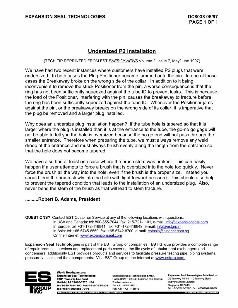
We have had two recent instances where customers have installed P2 plugs that were undersized. In both cases the Plug Positioner became jammed onto the pin. In one of those cases the Breakaway broke on the wrong side of the collar. In addition to it being inconvenient to remove the stuck Positioner from the pin, a worse consequence is that the ring has not been sufficiently squeezed against the tube ID to prevent leaks. This is because the load of the Positioner, interfering with the pin, causes the breakaway to fracture before the ring has been sufficiently squeezed against the tube ID. Whenever the Positioner jams against the pin, or the breakaway breaks on the wrong side of its collar, it is imperative that the plug be removed and a larger plug installed. Why does an undersize plug installation happen? If the tube hole is tapered so that it is larger where the plug is installed than it is at the entrance to the tube, the go-no go gage will not be able to tell you the hole is oversized because the no go end will not pass through the smaller entrance. Therefore when preparing the tube, we must always remove any weld droop at the entrance and must always brush evenly along the length from the entrance so that the hole does not become tapered. We have also had at least one case where the brush stem was broken. This can easily happen if a user attempts to force a brush that is oversized into the hole too quickly. Never force the brush all the way into the hole, even if the brush is the proper size. Instead you should feed the brush slowly into the hole with light forward pressure. This should also help to prevent the tapered condition that leads to the installation of an undersized plug. Also, never bend the stem of the brush as that will lead to stem fracture. ..........Robert B. Adams, President QUESTIONS? Contact EST Customer Service at any of the following locations with questions.
In USA and Canada: tel: 800-355-7044, fax: 215-721-1101, e-mail: [email protected] In Europe: tel: +31-172-418841, fax: +31-172-418849; e-mail: [email protected] In Asia: tel: +65-6745-8560, fax: +65-6742-8700, e-mail: [email protected] On the Internet: www.expansionseal.com
Expansion Seal Technologies is part of the EST Group of companies. EST Group provides a complete range of repair products, services and replacement parts covering the life cycle of tubular heat exchangers and condensers; additionally EST provides products and services to facilitate pressure testing pipe, piping systems, pressure vessels and their components. Visit EST Group on the internet at www.estgrp.com.

EXPANSION SEAL TECHNOLOGIES DC9680 03/03 PAGE 1 OF 1
POP-A-PLUG II (P2) SIZING FOR EXPANDED HEAT EXCHANGER TUBES
WALL TUBE OD THICKNESS DECIMAL
BWG 1/2” (12.7 mm)
5/8” (15.88 mm)
3/4” (19.05 mm)
7/8” (22.23 mm)
1” (25.40 mm)
8 0.165” (4.19 mm)
ID 0.453” (11.51 mm)
0.578 (14.68 mm)
0.703 (17.86 mm)
PLUG P2-440 P2-580 P2-700 9 0.148
(3.76 mm) ID 0.484
(12.29 mm) 0.609
(15.47 mm) 0.734
(18.64 mm) PLUG P2-480 P2-600 P2-720
10 0.134 (3.40 mm)
ID 0.509 (12.93 mm)
0.634 (16.10 mm)
0.759 (19.28 mm)
PLUG P2-500 P2-620 P2-760 11 0.120
(3.05 mm) ID 0.409
(10.39 mm) 0.534
(13.56 mm) 0.659
(16.74 mm) 0.784
(19.91 mm) PLUG P2-400 P2-520 P2-660 P2-780
12 0.109 (2.77 mm)
ID 0.429 (10.90 mm)
0.554 (14.07 mm)
0.679 (17.25 mm)
0.804 (20.42 mm)
PLUG P2-420 P2-540 P2-680 P2-800 13 0.095
(2.41 mm) ID 0.454
(11.53 mm) 0.579
(14.71 mm) 0.704
(17.88 mm) 0.829
(21.06 mm) PLUG P2-440 P2-580 P2-700 P2-820
14 0.083 (2.11 mm)
ID 0.476 (12.09 mm)
0.601 (15.27 mm)
0.726 (18.44 mm)
0.851 (21.62 mm)
PLUG P2-480 P2-600 P2-720 P2-840 15 0.072
(1.83 mm) ID 0.495
(12.57 mm) 0.620
(15.75 mm) 0.745
(18.92 mm) 0.870
(22.10 mm) PLUG P2-500 P2-620 P2-740 P2-860
16 0.065 (1.65 mm)
ID 0.508 (12.90 mm)
0.633 (16.08 mm)
0.758 (19.25 mm)
0.883 (22.43 mm)
PLUG P2-500 P2-620 P2-760 P2-880 17 0.058
(1.47 mm) ID 0.521
(13.23 mm) 0.646
(16.41 mm) 0.771
(19.58 mm) 0.896
(22.76 mm) PLUG P2-520 P2-640 P2-760 P2-900
18 0.049 (1.24 mm)
ID 0.412 (10.46 mm)
0.537 (13.64 mm)
0.662 (16.81 mm)
0.787 (19.99 mm)
0.912 (23.16 mm)
PLUG P2-400 P2-540 P2-660 P2-780 P2-900 19 0.042
(1.07 mm) ID 0.424
(10.77 mm) 0.549
(13.94 mm) 0.674
(17.12 mm) 0.799
(20.29 mm) 0.924
(23.47 mm) PLUG P2-420 P2-540 P2-660 P2-800 P2-920
20 0.035 (0.89 mm)
ID 0.437 (11.10 mm)
0.562 (14.27 mm)
0.687 (17.45 mm)
0.812 (20.62 mm)
0.937 (23.80 mm)
PLUG P2-440 P2-560 P2-680 P2-800 P2-940 21 0.032
(0.81 mm) ID 0.442
(11.23 mm) 0.567
(14.40 mm) 0.692
(17.58 mm) 0.817
(20.75 mm) 0.942
(23.93 mm) PLUG P2-440 P2-560 P2-700 P2-820 P2-940
22 0.028 (0.71 mm)
ID 0.450 (11.43 mm)
0.575 (14.61 mm)
0.700 (17.78 mm)
0.825 (20.96 mm)
0.950 (24.13 mm)
PLUG P2-440 P2-580 P2-700 P2-820 P2-940 23 0.025
(0.64 mm) ID 0.455
(11.56 mm) 0.580
(14.73 mm) 0.705
(17.91 mm) 0.830
(21.08 mm) 0.955
(24.26 mm) PLUG P2-460 P2-580 P2-700 P2-820 P2-960
24 0.022 (0.56 mm)
ID 0.460 (11.68 mm)
0.585 (14.86 mm)
0.710 (18.03 mm)
0.835 (21.21 mm)
0.960 (24.38 mm)
PLUG P2-460 P2-580 P2-700 P2-840 P2-960 NOTE: Heat exchanger tube ID’s often vary between inlet & outlet side. More than one P2 size may be required. If there is no previous experience indicating the correct P2 size and the tube ID’s cannot be measured it is recommended to have (2) consecutive P2 sizes on hand. EXAMPLE: A feedwater heater with ¾” x 14 BWG tubes is being plugged for the first time. EST recommends enough P2-600 plugs to seal every tube and approximately half that amount of P2-620. QUESTIONS? Contact EST Customer Service at any of the following locations with questions.
In USA and Canada: tel: 800-355-7044, fax: 215-721-1101, e-mail: [email protected] In Europe: tel: +31-172-418841, fax: +31-172-418849; e-mail: [email protected] In Asia: tel: +65-6745-8560, fax: +65-6742-8700, e-mail: [email protected] On the Internet: www.expansionseal.com
Expansion Seal Technologies is part of the EST Group of companies. EST Group provides a complete range of repair products, services and replacement parts covering the life cycle of tubular heat exchangers and condensers; additionally EST provides products and services to facilitate pressure testing pipe, piping systems, pressure vessels and their components. Visit EST Group on the internet at www.estgrp.com.