P1394b Draft Standard for a High Performance Serial Bus ... · PDF fileand it could not handle...
398
' 2001 IEEE This is an unapproved standards draft, subject to change 1 P1394b Draft 1.3.1 Oct 15, 2001 P1394b Draft Standard for a High Performance Serial Bus (Supplement) Sponsor Microprocessor and Microcomputer Standards Committee of the IEEE Computer Society Not yet Approved by IEEE Standards Board Not yet Approved by American National Standards Institute Abstract: Supplemental information for a high-speed serial bus that integrates well with most IEEE standard 32-bit and 64- bit parallel buses is specified. It is intended to extend the usefulness of a low-cost interconnect between external peripherals. This standard follows the IEEE Std 1212r-2001 Command and Status Register (CSR) architecture. Keywords: bus, computers, high-speed serial bus, interconnect The Institute of Electrical And Electronics Engineers, Inc. 345 East 47th Street, New York, NY 10017-2394, USA Copyright ' 2001 by the Institute of Electrical And Electronics Engineers, Inc. All rights reserved. Published 1996. Printed in the United States of America. ISBN x-xxxxx-xxx-x This is an unapproved IEEE Standards Draft, subject to change. Permission is hereby granted for IEEE Standards Committee participants to reproduce this document for purposes of IEEE standardization activities, including balloting and coordination. If this document is to be submitted to ISO or IEC, notification shall be given to the IEEE Copyright Administrator. Permission is also granted for member bodies and technical committees of ISO and IEC to reproduce this document for purposes of developing a national position. Other entities seeking permission to reproduce this document for these or other uses must contact the IEEE Standards Department for the appropriate license. Use of the information contained in this unapproved draft is at your own risk.
Transcript of P1394b Draft Standard for a High Performance Serial Bus ... · PDF fileand it could not handle...
P1394b Draft 1.3.1Oct 15, 2001
P1394bDraft Standard for aHigh Performance Serial Bus (Supplement)
Sponsor
Microprocessor and Microcomputer Standards Committeeof theIEEE Computer Society
Not yet Approved by
IEEE Standards Board
Not yet Approved by
American National Standards Institute
Abstract: Supplemental information for a high-speed serial bus that integrates well with most IEEE standard 32-bit and 64-bit parallel buses is specified. It is intended to extend the usefulness of a low-cost interconnect between external peripherals.This standard follows the IEEE Std 1212r-2001 Command and Status Register (CSR) architecture.Keywords: bus, computers, high-speed serial bus, interconnect
The Institute of Electrical And Electronics Engineers, Inc.345 East 47th Street, New York, NY 10017-2394, USA
Copyright © 2001 by the Institute of Electrical And Electronics Engineers, Inc.All rights reserved. Published 1996. Printed in the United States of America.
ISBN x-xxxxx-xxx-x
This is an unapproved IEEE Standards Draft, subject to change. Permission is hereby granted for IEEE Standards Committee participants to reproduce this document for purposes of IEEE standardization activities, including balloting and coordination. If this document is to be submitted to ISO or IEC, notification shall be given to the IEEE Copyright Administrator. Permission is also granted for member bodies and technical committees of ISO and IEC to reproduce this document for purposes of developing a national position. Other entities seeking permission to reproduce this document for these or other uses must contact the IEEE Standards Department for the appropriate license. Use of the information contained in this unapproved draft is at your own risk.
© 2001 IEEE This is an unapproved standards draft, subject to change 1
High Performance Serial Bus (Supplement) P1394b Draft 1.3.1
Oct 15, 2001
IEEE Standards documents are developed within the IEEE Societies and the Standards Coordinating Committees of theIEEE Standards Board. Members of the committees serve voluntarily and without compensation. They are not necessarilymembers of the Institute. The standards developed within IEEE represent a consensus of the broad expertise on the sub-ject within the Institute as well as those activities outside of IEEE that have expressed an interest in participating in thedevelopment of the standard.
Use of an IEEE Standard is wholly voluntary. The existence of an IEEE Standard does not imply that there are no otherways to produce, test, measure, purchase, market, or provide other goods and services related to the scope of the IEEEStandard. Furthermore, the viewpoint expressed at the time a standard is approved and issued is subject to change broughtabout through developments in the state of the art and comments received from users of the standard. Every IEEE Stan-dard is subjected to review at least every five years for revision or reaffirmation. When a document is more than fiveyears old and has not been reaffirmed, it is reasonable to conclude that its contents, although still of some value, do notwholly reflect the present state of the art. Users are cautioned to check to determine that they have the latest edition ofany IEEE Standard.
Comments for revision of IEEE Standards are welcome from any interested party, regardless of membership affiliationwith IEEE. Suggestions for changes in documents should be in the form of a proposed change of text, together withappropriate supporting comments.
Interpretations: Occasionally questions may arise regarding the meaning of portions of standards as they relate to specificapplications. When the need for interpretations is brought to the attention of IEEE, the Institute will initiate action to pre-pare appropriate responses. Since IEEE Standards represent a consensus of all concerned interests, it is important toensure that any interpretation has also received the concurrence of a balance of interests. For this reason, IEEE and themembers of its societies and Standards Coordinating Committees are not able to provide an instant response to interpre-tation requests except in those cases where the matter has previously received formal consideration.
Comments on standards and requests for interpretations should be addressed to:
Secretary, IEEE Standards Board445 Hoes LaneP.O. Box 1331Piscataway, NJ 08855-1331USA
Authorization to photocopy portions of any individual standard for internal or personal use is granted by the Institute ofElectrical and Electronics Engineers, Inc., provided that the appropriate fee is paid to Copyright Clearance Center. Toarrange for payment of licensing fee, please contact Copyright Clearance Center, Customer Service, 222 Rosewood Drive,Danvers, MA 01923 USA; (508) 750-8400. Permission to photocopy portions of any individual standard for educationalclassroom use can also be obtained through the Copyright Clearance Center.
Note: Attention is called to the possibility that implementation of this standardmay require use of subject matter covered by patent rights. By publication of thisstandard, no position is taken with respect to the existence or validity of anypatent rights in connection therewith. The IEEE shall not be responsible for iden-tifying all patents for which a license may be required by an IEEE standard or forconducting inquiries into the legal validity or scope of those patents that arebrought to its attention.
2 This is an unapproved standards draft, subject to change © 2001 IEEE
P1394b Draft 1.3.1 High Performance Serial Bus (Supplement)Oct 15, 2001
Introduction
Work on this standard was begun in the winter of 1997 at a meeting of the 1394TA in Eindhoven. By that time, it hadbecome evident that 1994-1995 was going to be widely deployed and that many devices, especially new, digital consumerproducts, were going to have 1394 as the primary external interface. In the first meetings of this group, there was consid-erable sentiment for broadening the number and types of devices that would be able to use the 1394 interface therebymaking the interface more valuable to the end user. While attempting to broaden the scope of 1394, two barriers were dis-covered that made wider deployment of 1394 difficult: the interface was constrained to operate over a fairly short distanceand it could not handle higher data rates.
After some preliminary investigations, the group concluded that these problems were best solved by a change in coding.While the data-strobe coding used in IEEE std 1394-1995 was a simple, self-clocking scheme, the fact that it is not DCbalanced made it impractical to use over longer distances. Furthermore, accumulated skew on a long distance connectionmake it hard to maintain the timing relationships between the data and the strobe lines, especially at higher data rates. Thegroup rapidly converged on the notion of using a variant of 8b-10b coding developed by IBM for the longer distances andhigher speeds defined in this standard. In cases where the connection between devices was copper cable of 5M or less,some or all of the ports on a new PHY developed to support this standard could be able to signal using either data-strobeor the new signaling scheme (dubbed Beta mode). These bi-lingual ports would be able to select the optimum signal-ing method for the connection and, thereby, be able to fully interoperate with existing IEEE std 1394-1995 and IEEE std1394a-2000 devices.
The new signalling system provided a route to solving a second major problem, i.e. the lack of scalability of the 1394-1995 arbitration scheme as signaling rates are increased. The use of 8B10B encoding allows the transmission of data tobe overlapped with the transmission of arbitration signals in the reverse direction. The use of overlapped arbitration isextended by one level of pipelineing, with the result that in a purely 1394b bus the need for arbitration gaps is entirelyeliminated. In fact, on a bus with all connections operating in Beta mode, the setting of gap count has no utility as the busis completely self-timed.
As work progressed, the group became interested in applying the new coding scheme to a large variety of interconnectmedia including plastic optical fiber, glass optical fiber and UTP5. This greatly expanded the scope of the work and madeit necessary to divide the P1394B working group into various task groups. It was the leaders of these group who werelargely responsible for the development of this specification. Because of the length of the project, some of the workinggroups had more than one leader. The working groups, their leaders and their contributions are:
- Glass Fiber - Colin Whitby-Strevens - This group adopted the work from the FibreChannel specification for use in1394. The jitter work done in this group was adapted for use in all the media.
- Plastic Fiber - Taka Fujimori, Shuntaro Yamazaki, Victoria K.M. Teng, Kazuki Nakamura - This group actually end-ed up developing a standard around a single connector that allowed inter-operation and inter-mating of both plasticfiber or large-diameter HPCF. This connector can be used at a speed of S100.
- UTP5 - Colin Whitby-Strevens, Alistair Coles - This group built on work done in the 100BaseT standard with exten-sive changes to simplify the coding and transmission over UTP5.
- Standard Electrical - Eric Hannah - This group provided the electrical characteristics for the base-line PHY. This re-quired a great deal of simulation work by Eric in support of the Cable & Connector task group.
- Start-up Protocol - Colin Whitby-Strevens - This group created the mechanisms that allow a B PHY to determine ifit is attached to another B PHY and to select the signaling frequency before the connection is completed. PengZhang and Jim Nave proposed the speed signaling scheme using a toning mechanisms. This was enhances by ColinWhitby-Strevens to deal with all the connectivity aspects of B-ports. The loop-breaking protocol was developed byJerry Hauck and David Wooten.
- Cable & Connector - Max Bassler - This group originally tried to characterize the 4 and 6 circuit connectors used in1394-1995 and 1394a-2000 for use at the higher speeds defined in this standard. This work was abandon after twoyears of work and a new, small form-factor connector was developed by Dave Brunker for use on devices capable ofBeta-mode signaling.
- Protocol Accelerations - David LaFollette, Alistair Coles, Mike Teener - This group developed the BOSS arbitrationscheme that is the basis for all of the arbitration and control. The original concepts were proposed by David LaFol-lette and Jerry Hauck. Their work was supplemented by contributions from Alistair Coles, Mike Teener, Jim Skid-more, and David Wooten.
© 2001 IEEE This is an unapproved standards draft, subject to change 3

High Performance Serial Bus (Supplement) P1394b Draft 1.3.1
Oct 15, 2001
- Port Logic - Alistair Coles - This group developed the coding and scrambling methods used for Beta mode ports.Alistair Coles and Eric Deliot developed the single character control codes and arbitration tokens. This group alsoselected the scrambling method for the symbols. The method of dealing with deletable symbols was adapted fromFibreChannel by Jerry Hauck and Mike Teener.
- Simulation - Jerry Hauck - This group did some computer simulations of the various pieces of the B PHY but mostof the simulation was mental and took place in Mr. Haucks head. This turned out to be a much more efficient meth-od of finding problems than a computer simulation.
- Low-power - Richard Churchill, Steve Bard - This group developed the standby-restore protocol.- PHY-link/PIL-FOP - Martin Sodos, Sean Killeen, David Wooten - This group developed the source synchronous ver-
sion of the PHY-link interface and the PIL-FOP interface. The point-to-point packet protocol for sending in-bandstatus and register information between the PIL and FOP was developed by Jerry Hauck and David Wooten.
- C-Code - Colin Whitby-Strevens - This was not a formal task group but the work that Colin did in developing andmaintaining the C code for the standard bears special recognition.
The Working Group first met under the chairmanship of Mike Teener in January 1997. David Wooten became chair withina few months, and the Working Group continued to meet approximately every month until the editorial work was com-pleted in October of 1999 at which time the Working Group voted to go to ballot. The proposed standard was balloted inMarch and April of 2000 with over 80% of the votes in favor. A Ballot Response Committee (BRC) was formed to reviewthe comments. Those comments pointed out many significant omissions and errors in the draft that the BRC correctedover the next seven months of meetings. The BRC completed its work on this standard in February of 2001.
The ballot for the Febuary, 2001 version of the standard passed but with comments that pointed out some flaws thatwould need to be corrected before the standard could be released. The BRC met several times from June to Septemberand completed work on a new version of the standard in September of 2001.
4 This is an unapproved standards draft, subject to change © 2001 IEEE
P1394b Draft 1.3.1 High Performance Serial Bus (Supplement)Oct 15, 2001
Patent notice
Note: Attention is called to the possibility that implementation of this standard may require use of subject matter coveredby patent rights. By publication of this standard, no position is taken with respect to the existence or validity of any patentrights in connection therewith. The IEEE shall not be responsible for identifying all patents for which a license may berequired by an IEEE standard or for conducting inquiries into the legal validity or scope of those patents that are broughtto its attention.
The patent holder has, however, filed a statement of assurance that it will grant a license under these rights withoutcompensation or under reasonable rates and nondiscriminatory, reasonable terms and conditions to all applicants desiringto obtain such a license. The IEEE makes no representation as to the reasonableness of rates and/or terms and conditionsof the license agreement offered by the patent holder. Contact information may be obtained from the IEEE StandardsDepartment.
The following is a list of major participants in the IEEE P1394b working group (those that attended at least three working group meetings.).
Bill Anderson
Tatsuya Arai
Oleg Awsienko
Richard Baker
Steve Bard
David Barnum
Max Bassler
Charles Brill
Dave Brown
Mike Brown
Dave Brunker
Jim Busse
Don Chambers
Dao-Long Chen
Richard Churchill
Dan Colegrove
Alistair Coles
Mike Coletta
Eric Deliot
Chris Dorsey
Firooz Farhoomand
Stephen Finch
Mike Fogg
Tony Foster
John Fuller
Nobuo Furuya
Dave Gampell
Bob Gannon
Mike Gardner
Eric Hannah
Jerry Hauck
Keith Heilmann
John Hill
Daisuke Hiraoka
Jack Hollins
Derek Imschweiler
Tatsuo Inoue
David Instone
David James
David Johnson
Tom Jones
Prashant Kanhere
Marcus Kellerman
Al Kelley
Sean Killeen
Akihito Kuwabara
Dave LaFollette
Farrukh Latif
Thang Le
Paul Levy
Francesco Liburdi
Robert Liu
John Lopata
Gerald Marazas
Jun-ichi Matsuda
Edward McDonnell
Daniel Meirsman
Jack Merrow
Takatoshi Mizoguchi
Reza Moattar
Palanisamy Mohanraj
Cyrus Momeni
Karl Nakamura
James Nave
Jim Nelson
Richard Nesin
Bill Northey
Takayuki Nyu
Ozay Oktay
Bijit Patel
James Piccione
Bill Prouty
Dennis Rehm
Kyozo Saito
Tomoki Saito
Brad Saunders
Dick Scheel
D. C. Sessions
Masood Shariff
Robbie Shergill
Jim Skidmore
David Smith
Michael Smith
John Smolka
Ron Soderstrom
Martin Sodos
John Ta
Ju-Ching Tang
Ken Taylor
Michael Johas Teener
Peter Teng
Victoria Teng
Tom Thatcher
David Thompson
Toru Ueda
Sushant Verman
Hirosha Wakai
Kenji Watanabe
Yuji Watanabe
Colin Whitby-Strevens
David Wooten
Shuntaro Yamazaki
Niwa Yoshikatsu
Len Young
Patrick Yu
Peng Zhang
© 2001 IEEE This is an unapproved standards draft, subject to change 5

High Performance Serial Bus (Supplement) P1394b Draft 1.3.1
Oct 15, 2001
The following persons served on the ballot response committee (attended three or more meetings):
The following persons were members of the balloting group:
Steve Bard
Max Bassler
Eric Hannah
Jerry Hauck
Firooz Farhoomand
Peter Johansson
Teruaki Kawaguchi
Sam Khoo
Susumu Morikura
Kazuki Nakamura
Sean Killeen
Jim Skidmore
Kazuki Sogabe
Michael Johas Teener
Victoria Teng
David Thompson
Colin Whitby-Strevens
David Wooten
6 This is an unapproved standards draft, subject to change © 2001 IEEE
High Performance Serial Bus (Supplement) P1394b Draft 1.3.1
Oct 15, 2001
If the IEEE Standards Board approves this draft standard, it might have the following membership:
E. G. Al Kiener, ChairDonald C. Loughry, Vice ChairAndrew G. Salem, Secretary
Other candiates for inclusion might be the following nonvoting IEEE Standards Board liaisons:
Mary Lynne NielsenIEEE Standards Project Editor
Gilles A. Baril
Clyde R. Camp
Joseph A. Cannatelli
Stephen L. Diamond
Harold E. Epstein
Donald C. Fleckenstein
Jay Forster*
Donald N. Heirman
Richard J. Holleman
Jim Isaak
Ben C. Johnson
Sonny Kasturi
Lorraine C. Kevra
Ivor N. Knight
Joseph L. Koepfinger*
D. N. Jim Logothetis
L. Bruce McClung
Marco W. Migliaro
Mary Lou Padgett
John W. Pope
Arthur K. Reilly
Gary S. Robinson
Ingo Rüsch
Chee Kiow Tan
Leonard L. Tripp
Howard L. Wolfman
*Member Emeritus
Satish K. Aggarwal
Steve Sharkey
Robert E. Hebner
Chester C. Taylor
7 This is an unapproved standards draft, subject to change © 2001 IEEE

High Performance Serial Bus (Supplement) P1394b Draft 1.3.1
Oct 15, 2001
8 This is an unapproved standards draft, subject to change © 2001 IEEE

P1394b Draft 1.3.1 High Performance Serial Bus (Supplement)Oct 15, 2001
Table of Contents
Introduction .......................................................................................................................................................................... 3Patent notice ......................................................................................................................................................................... 5
Table of Contents .................................................................................................................................................................. 9
List of Figures .................................................................................................................................................................... 13
List of Tables ...................................................................................................................................................................... 17
1. Overview ......................................................................................................................................................................... 21
1.1 Scope ................................................................................................................................................................. 211.2 Purpose .............................................................................................................................................................. 211.3 Document organization ...................................................................................................................................... 221.4 Service model .................................................................................................................................................... 221.5 Document notation............................................................................................................................................. 23
2. References ....................................................................................................................................................................... 31
3. Definitions and abbreviations .......................................................................................................................................... 33
3.1 Conformance glossary........................................................................................................................................ 333.2 Technical glossary.............................................................................................................................................. 33
4. Summary description....................................................................................................................................................... 43
4.1 The relationship to IEEE Std 1394a-2000.......................................................................................................... 434.2 Faster and further ............................................................................................................................................... 434.3 Nomenclature..................................................................................................................................................... 444.4 Media - common properties ............................................................................................................................... 454.5 Arbitration improvements .................................................................................................................................. 464.6 PHY-Link interface, general interface characteristics ........................................................................................ 524.7 Miscellaneous features....................................................................................................................................... 53
5. Copper physical medium dependent cable media attachment.......................................................................................... 55
5.1 Connectors ......................................................................................................................................................... 555.2 Cables ................................................................................................................................................................ 755.3 Connector and cable assembly performance criteria .......................................................................................... 815.4 Signal propagation performance criteria ............................................................................................................ 895.5 Termination and Isolation .................................................................................................................................. 955.6 Ground Isolation ................................................................................................................................................ 97
6. Short-Haul copper physical medium dependent electrical specification.........................................................................101
6.1 Interfaces ..........................................................................................................................................................1016.2 Transmitter electrical specifications..................................................................................................................1026.3 Receiver electrical specifications ......................................................................................................................1056.4 Electrical measurements ...................................................................................................................................1066.5 DC biasing ........................................................................................................................................................1076.6 Toning and Signal Detect ..................................................................................................................................1076.7 Jitter ..................................................................................................................................................................110
© 2001 IEEE This is an unapproved standards draft, subject to change 9
P1394b Draft 1.3.1 High Performance Serial Bus (Supplement)Oct 15, 2001
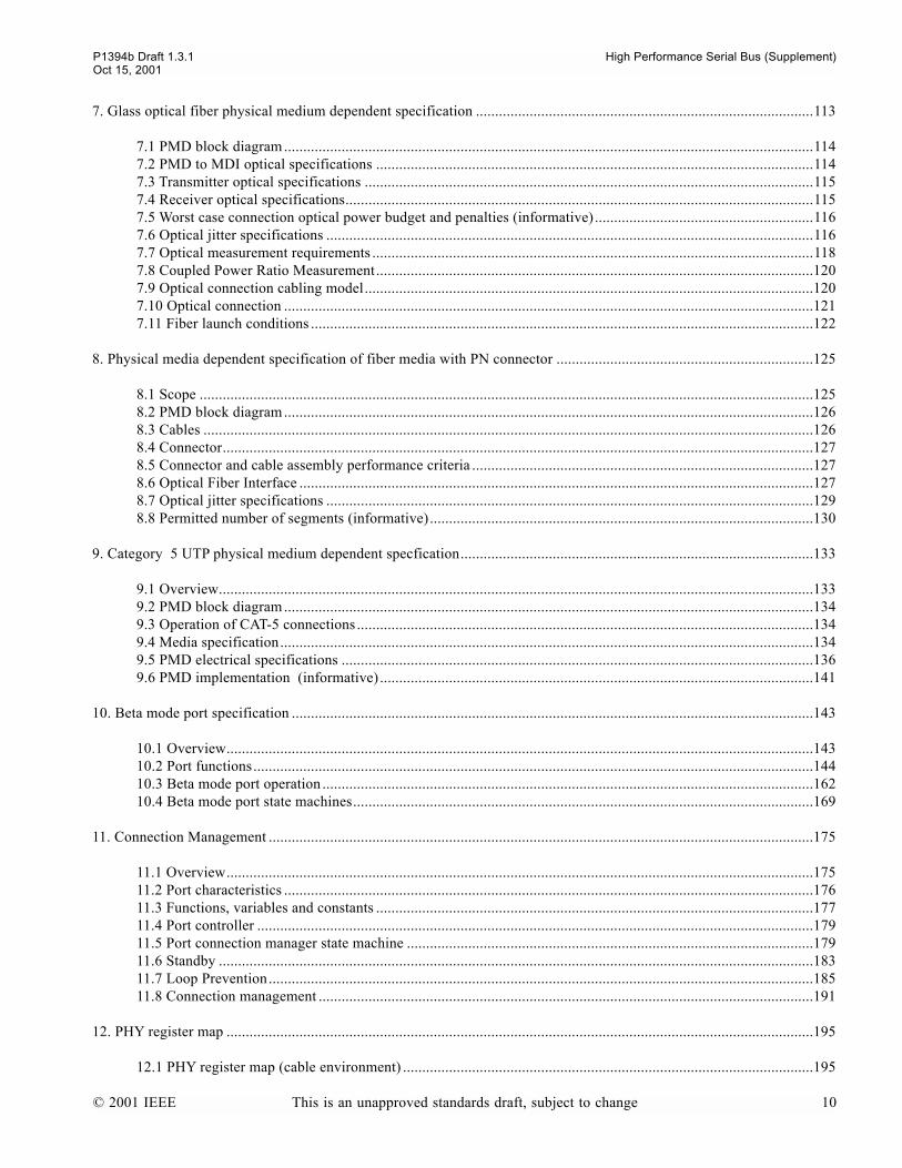
7. Glass optical fiber physical medium dependent specification ........................................................................................113
7.1 PMD block diagram..........................................................................................................................................1147.2 PMD to MDI optical specifications ..................................................................................................................1147.3 Transmitter optical specifications .....................................................................................................................1157.4 Receiver optical specifications..........................................................................................................................1157.5 Worst case connection optical power budget and penalties (informative) .........................................................1167.6 Optical jitter specifications ...............................................................................................................................1167.7 Optical measurement requirements ...................................................................................................................1187.8 Coupled Power Ratio Measurement..................................................................................................................1207.9 Optical connection cabling model.....................................................................................................................1207.10 Optical connection ..........................................................................................................................................1217.11 Fiber launch conditions ...................................................................................................................................122
8. Physical media dependent specification of fiber media with PN connector ...................................................................125
8.1 Scope ................................................................................................................................................................1258.2 PMD block diagram..........................................................................................................................................1268.3 Cables ...............................................................................................................................................................1268.4 Connector..........................................................................................................................................................1278.5 Connector and cable assembly performance criteria .........................................................................................1278.6 Optical Fiber Interface ......................................................................................................................................1278.7 Optical jitter specifications ...............................................................................................................................1298.8 Permitted number of segments (informative)....................................................................................................130
9. Category 5 UTP physical medium dependent specfication............................................................................................133
9.1 Overview...........................................................................................................................................................1339.2 PMD block diagram..........................................................................................................................................1349.3 Operation of CAT-5 connections .......................................................................................................................1349.4 Media specification...........................................................................................................................................1349.5 PMD electrical specifications ...........................................................................................................................1369.6 PMD implementation (informative) .................................................................................................................141
10. Beta mode port specification ........................................................................................................................................143
10.1 Overview.........................................................................................................................................................14310.2 Port functions..................................................................................................................................................14410.3 Beta mode port operation ................................................................................................................................16210.4 Beta mode port state machines........................................................................................................................169
11. Connection Management ..............................................................................................................................................175
11.1 Overview.........................................................................................................................................................17511.2 Port characteristics ..........................................................................................................................................17611.3 Functions, variables and constants ..................................................................................................................17711.4 Port controller .................................................................................................................................................17911.5 Port connection manager state machine ..........................................................................................................17911.6 Standby ...........................................................................................................................................................18311.7 Loop Prevention..............................................................................................................................................18511.8 Connection management .................................................................................................................................191
12. PHY register map .........................................................................................................................................................195
12.1 PHY register map (cable environment) ...........................................................................................................195
© 2001 IEEE This is an unapproved standards draft, subject to change 10

P1394b Draft 1.3.1 High Performance Serial Bus (Supplement)Oct 15, 2001
12.2 Integrated link and PHY .................................................................................................................................202
13. Data routing, arbitration and control ............................................................................................................................203
13.1 Overview.........................................................................................................................................................20313.2 PHY layer services..........................................................................................................................................20413.3 PHY facilities..................................................................................................................................................21513.4 Cable physical layer operation ........................................................................................................................227
14. B PHY link Interface (parallel)..................................................................................................................................249
14.1 B PHY-link Interface Characteristics ..............................................................................................................24914.2 PHY-link Interface Signals.............................................................................................................................25014.3 Interface Initialization, Reset and Disable ......................................................................................................25214.4 Link-On and Interrupt Indications...................................................................................................................25614.5 Link Requests and Notifications .....................................................................................................................25714.6 Interface Data Transfers ..................................................................................................................................26314.7 Format of Received and Transmitted Data ......................................................................................................27014.8 Status Transfers and Notifications from the PHY ...........................................................................................27214.9 Delays affecting interoperability of PHYs and Links.....................................................................................27614.10 Legacy link support.......................................................................................................................................27714.11 Electrical characteristics................................................................................................................................278
15. PIL-FOP Serial Interface .............................................................................................................................................287
15.1 Operating Model .............................................................................................................................................28715.2 PIL-FOP Connection Management .................................................................................................................28815.3 Serial Bus Configuration Request Types not Carried over the PIL-FOP Interface ..........................................29015.4 Point-to-point Packet Protocol ........................................................................................................................290
16. C code...........................................................................................................................................................................293
16.1 Common declarations and functions ...............................................................................................................29316.2 Connection Management routines...................................................................................................................30616.3 Port state machine actions...............................................................................................................................32516.4 Border arbitration actions and conditions .......................................................................................................34216.5 Border Arbitration...........................................................................................................................................374
Annex A. Annex K IEEE standard 1394-1995 supplement -- bulk cable specification ......................................................385
A.1 Reference K.3 Signal pair characteristic impedance ........................................................................................385A.2 Reference K.4 Signal pair attenuation..............................................................................................................385A.3 Reference K.5 Signal pair velocity of propagation (TDR) ...............................................................................386A.4 Reference K.5 Signal pair velocity of propagation (Freq. sweep)....................................................................386A.5 Rise and fall time .............................................................................................................................................387A.6 Static Shield Isolation (insulation resistance)...................................................................................................388
Annex B. Jitter measurements (normative) ........................................................................................................................391
B.1 Test patterns .....................................................................................................................................................391B.2 Random pattern (SB_RPAT).............................................................................................................................391B.3 Receive jitter tolerance pattern (SB_JTPAT) ....................................................................................................391B.4 Supply noise test sequence (SB_SPAT)............................................................................................................392
Annex C. Connection status change (informative) .............................................................................................................393
© 2001 IEEE This is an unapproved standards draft, subject to change 11

P1394b Draft 1.3.1 High Performance Serial Bus (Supplement)Oct 15, 2001
Index of C-code functions .................................................................................................................................................395
© 2001 IEEE This is an unapproved standards draft, subject to change 12
P1394b Draft 1.3.1 High Performance Serial Bus (Supplement)Oct 15, 2001
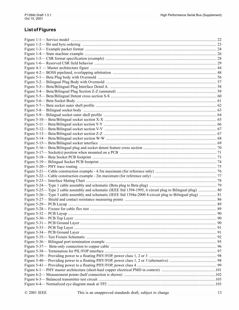
List of Figures
Figure 1-1 Service model ............................................................................................................................................... 22Figure 1-2 Bit and byte ordering .................................................................................................................................... 23Figure 1-3 Example packet format ................................................................................................................................. 24Figure 1-4 State machine example .................................................................................................................................. 26Figure 1-5 CSR format specification (example) ............................................................................................................. 28Figure 1-6 Reserved CSR field behavior ........................................................................................................................ 29Figure 4-1 Master architecture figure ............................................................................................................................ 44Figure 4-2 BOSS pipelined, overlapping arbitration ...................................................................................................... 48Figure 5-1 Beta Plug body with Overmold ..................................................................................................................... 56Figure 5-2 Bilingual Plug Body with Overmold ............................................................................................................. 57Figure 5-3 Beta/Bilingual Plug Interface Detail A. ......................................................................................................... 58Figure 5-4 Beta/Bilingual Plug Section Z-Z (unmated) .................................................................................................. 59Figure 5-5 Beta/Bilingual Detent cross section S-S ........................................................................................................ 60Figure 5-6 Beta Socket Body .......................................................................................................................................... 61Figure 5-7 Beta socket outer shell profile ....................................................................................................................... 62Figure 5-8 Bilingual socket body ................................................................................................................................... 63Figure 5-9 Bilingual socket outer shell profile ............................................................................................................... 64Figure 5-10 Beta/Bilingual socket section X-X .............................................................................................................. 65Figure 5-11 Beta/Bilingual socket section Y-Y ............................................................................................................... 66Figure 5-12 Beta/Bilingual socket section V-V .............................................................................................................. 67Figure 5-13 Beta/Bilingual socket section Z-Z ............................................................................................................... 67Figure 5-14 Beta/Bilingual socket section W-W ............................................................................................................. 68Figure 5-15 Beta/Bilingual socket interface ................................................................................................................... 69Figure 5-16 Beta/Bilingual plug and socket detent feature cross section ........................................................................ 70Figure 5-17 Socket(s) position when mounted on a PCB ............................................................................................... 71Figure 5-18 Beta Socket PCB footprint .......................................................................................................................... 73Figure 5-19 Bilingual Socket PCB footprint ................................................................................................................... 74Figure 5-20 PHY trace routing ....................................................................................................................................... 75Figure 5-21 Cable construction example - 4.5m maximum (for reference only) ............................................................ 76Figure 5-22 Cable construction example - 2m maximum (for reference only) ............................................................... 77Figure 5-23 Interface Mating Chart ................................................................................................................................ 78Figure 5-24 Type 1 cable assembly and schematic (Beta plug to Beta plug) .................................................................. 79Figure 5-25 Type 2 cable assembly and schematic (IEEE Std 1394-1995, 6 circuit plug to Bilingual plug) .................. 80Figure 5-26 Type 3 cable assembly and schematic (IEEE Std 1394a-2000 4-circuit plug to Bilingual plug) ................. 81Figure 5-27 Shield and contact resistance measuring points .......................................................................................... 86Figure 5-29 PCB Layup .................................................................................................................................................. 89Figure 5-28 Fixture for cable flex test ............................................................................................................................ 89Figure 5-32 PCB Layup .................................................................................................................................................. 90Figure 5-30 PCB Top Layer ............................................................................................................................................ 90Figure 5-31 PCB Ground Layer ...................................................................................................................................... 90Figure 5-33 PCB Top Layer ............................................................................................................................................ 91Figure 5-34 PCB Ground Layer ...................................................................................................................................... 91Figure 5-35 Test Fixture Schematic ................................................................................................................................ 92Figure 5-36 Bilingual port termination example ............................................................................................................. 95Figure 5-37 Beta-only connection to copper cable ........................................................................................................ 96Figure 5-38 Termination for PIL/FOP interface .............................................................................................................. 97Figure 5-39 Providing power to a floating PHY/FOP, power class 1, 2 or 3 .................................................................. 98Figure 5-40 Providing power to a floating PHY/FOP, power class 1, 2 or 3 (alternative) .............................................. 98Figure 5-41 Providing power to a floating PHY/FOP, power class 4 .............................................................................. 99Figure 6-1 PHY master architecture (short-haul copper electrical PMD in context) .....................................................101Figure 6-2 Measurement points (half connection is shown) ..........................................................................................102Figure 6-3 Balanced transmitter test circuit ...................................................................................................................103Figure 6-4 Normalized eye diagram mask at TP2 ..........................................................................................................103
© 2001 IEEE This is an unapproved standards draft, subject to change 13

High Performance Serial Bus (Supplement) P1394b Draft 1.3.1
Oct 15, 2001
Figure 6-5 Absolute eye diagram mask at TP2 ..............................................................................................................104Figure 6-6 Eye diagram mask at point-TP3 ...................................................................................................................105Figure 6-7 signal_detect timing parameters ..................................................................................................................109Figure 7-1 PHY master architecture (Glass optical fiber PMD in context) ................................................................... 113Figure 7-2 PMD block diagram ..................................................................................................................................... 114Figure 7-3 Transmitter eye mask definition ................................................................................................................... 119Figure 7-4 Optical Fiber Cabling model ........................................................................................................................121Figure 7-5 Duplex receptacle interface .........................................................................................................................122Figure 7-6 Duplex connection interface ........................................................................................................................122Figure 8-1 PHY master architecture ..............................................................................................................................125Figure 8-2 PMD block diagram .....................................................................................................................................126Figure 8-3 Plug connector interface ..............................................................................................................................127Figure 8-4 Receptacle connector interface ....................................................................................................................127Figure 9-1 PHY master architecture (CAT-5 UTP PMD in context) ..............................................................................133Figure 9-2 CAT 5 UTP PMD Interfaces ........................................................................................................................134Figure 9-3 Media interface connector ...........................................................................................................................136Figure 9-4 Signal mask for transmitted signal ...............................................................................................................138Figure 9-5 signal_detect timing parameters ..................................................................................................................141Figure 10-1 PHY master architecture (Data routing, arbitration and control interfaces in context) ..............................143Figure 10-2 Scrambling and coding functions (informative) .........................................................................................145Figure 10-3 Representation of the scrambler as a serial bit-shift register with parallel output ......................................150Figure 10-4 Scrambler schematic (data) (informative) ..................................................................................................151Figure 10-5 Scrambler schematic (request symbol) (informative) ................................................................................152Figure 10-6 Scrambler schematic (control) (informative) .............................................................................................153Figure 10-7 Structure of packet, packet delimiters and request types, with examples of coding process. .....................164Figure 10-8 Port transmit state machine ........................................................................................................................170Figure 10-9 Port receive state machine .........................................................................................................................172Figure 11-1 PHY master architecture (Data routing, arbitration and control interfaces in context) ...............................175Figure 11-2 Port connection manager state machine .....................................................................................................180Figure 11-3 Example of Dominant Subnets ...................................................................................................................185Figure 11-4 Speed code timing diagram ........................................................................................................................193Figure 11-5 Example speed negotiation .......................................................................................................................194Figure 12-1 Extended PHY register map for the cable environment .............................................................................195Figure 12-2 PHY register page 0: Port Status page .......................................................................................................199Figure 12-3 PHY register page 1: Vendor Identification page .......................................................................................201Figure 13-1 PHY master architecture (Data routing, arbitration and control interfaces in context) ..............................203Figure 13-2 Self-ID packet formats ..............................................................................................................................221Figure 13-3 Remote command packet format ...............................................................................................................222Figure 13-4 Remote confirmation packet format ...........................................................................................................223Figure 13-5 PHY configuration packet format ..............................................................................................................224Figure 13-6 Loop test packet format .............................................................................................................................225Figure 13-7 Bus reset state machine ..............................................................................................................................238Figure 13-8 Tree-ID state machine ................................................................................................................................240Figure 13-9 Self-ID state machine ................................................................................................................................242Figure 13-10 Border arbitration state machine ..............................................................................................................245Figure 14-1 PHY-link Interface Logical Signalling .......................................................................................................250Figure 14-2 Digital differentiator signal transformation ................................................................................................252Figure 14-3 LPS waveform when differentiated ............................................................................................................253Figure 14-4 PHY-link interface reset .............................................................................................................................254Figure 14-5 PHY-link interface disable .........................................................................................................................254Figure 14-6 LinkOn waveform ......................................................................................................................................256Figure 14-7 Link Request Format .................................................................................................................................261Figure 14-8 PHY-link Packet Receive Operation ..........................................................................................................265Figure 14-9 PHY-link Packet Transmit Operation, including optional HOLD cycles ...................................................267Figure 14-10 S100 Data transferred over 100 MHz, Single-edge clocking ...................................................................271
14 This is an unapproved standards draft, subject to change © 2001 IEEE

P1394b Draft 1.3.1 High Performance Serial Bus (Supplement)Oct 15, 2001
Figure 14-11 S200 Data transferred over 100 MHz, Single-edge clocking ...................................................................271Figure 14-12 S400 Data transferred over 100 MHz, Single-edge clocking ...................................................................271Figure 14-13 S800 Data transferred over 100 MHz, Single-edge clocking ...................................................................272Figure 14-14 Bus Status Transfer Format ......................................................................................................................273Figure 14-15 PHY Status Transfer Format ....................................................................................................................275Figure 14-16 Signal levels for rise and fall times ..........................................................................................................279Figure 14-17 transfer waveform at the source ...............................................................................................................280Figure 14-18 transfer waveform at the destination ........................................................................................................280Figure 14-19 Ground coupling circuit example .............................................................................................................281Figure 14-20 Capacitive isolation barrier circuit example for Ctl[0:1] and D[0:n] ........................................................282Figure 14-21 Capacitive isolation barrier circuit example for LinkOn ..........................................................................282Figure 14-23 Capacitive isolation barrier circuit example for LReq and PInt ...............................................................283Figure 14-22 Capacitive isolation barrier circuit example for LPS ...............................................................................283Figure 14-25 Bus Holder isolation circuit example for LReq, PInt, PClk, and LClk .....................................................284Figure 14-24 Capacitive isolation barrier circuit example for LClk and PClk ...............................................................284Figure 14-26 Bus Holder isolation circuit example for Ctl[0:1] and D[0:n] ..................................................................285Figure 15-1 Possible System Configuration using a fan-out PHY Device ....................................................................287Figure 15-2 Point-to-point Packet Format .....................................................................................................................290Figure 16-1 C code definitions ......................................................................................................................................293Figure 16-2 Data structures and enumerated types ........................................................................................................293Figure 16-3 PHY Services .............................................................................................................................................296Figure 16-4 Arbitration state machine internal variables ...............................................................................................299Figure 16-5 Variables shared between architectural elements .......................................................................................300Figure 16-6 Node level connection monitor functions and routines ..............................................................................306Figure 16-7 Port connection manager actions and conditions ........................................................................................312Figure 16-8 DS receive port ..........................................................................................................................................325Figure 16-9 DS transmit port .........................................................................................................................................327Figure 16-10 DS speed signaling filter ..........................................................................................................................329Figure 16-11 Beta mode port receive actions and conditions ........................................................................................330Figure 16-12 Beta mode port transmit actions and conditions .......................................................................................338Figure 16-13 Border transmit functions .........................................................................................................................342Figure 16-14 Border receive functions ..........................................................................................................................345Figure 16-15 PHY packet processing ............................................................................................................................349Figure 16-16 Legacy arbitration functions ....................................................................................................................351Figure 16-17 Border arbitration functions .....................................................................................................................353Figure 16-18 Background request processing ................................................................................................................359Figure 16-19 Reset actions ............................................................................................................................................366Figure 16-20 Tree ID actions .........................................................................................................................................369Figure 16-21 Self-ID actions .........................................................................................................................................370Figure 16-22 Idle actions ...............................................................................................................................................374Figure 16-23 Grant actions ............................................................................................................................................378Figure 16-24 Transmit actions .......................................................................................................................................379Figure 16-25 Receive actions ........................................................................................................................................382Figure A-1 Reference to rise and fall time ....................................................................................................................388
© 2001 IEEE This is an unapproved standards draft, subject to change 15

High Performance Serial Bus (Supplement) P1394b Draft 1.3.1
Oct 15, 2001
16 This is an unapproved standards draft, subject to change © 2001 IEEE
P1394b Draft 1.3.1 High Performance Serial Bus (Supplement)Oct 15, 2001
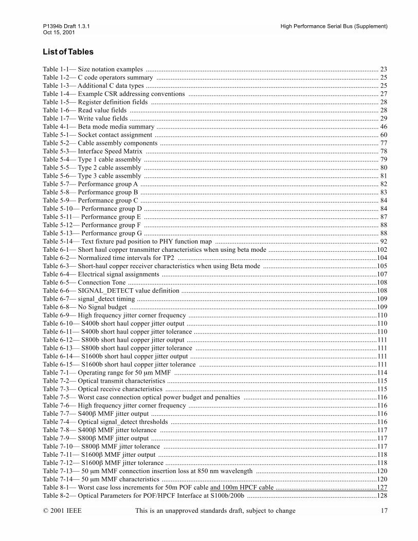
List of Tables
Table 1-1 Size notation examples ................................................................................................................................... 23Table 1-2 C code operators summary ............................................................................................................................. 25Table 1-3 Additional C data types ................................................................................................................................... 25Table 1-4 Example CSR addressing conventions ........................................................................................................... 27Table 1-5 Register definition fields ................................................................................................................................ 28Table 1-6 Read value fields ............................................................................................................................................ 28Table 1-7 Write value fields ............................................................................................................................................ 29Table 4-1 Beta mode media summary ............................................................................................................................. 46Table 5-1 Socket contact assignment .............................................................................................................................. 60Table 5-2 Cable assembly components ........................................................................................................................... 77Table 5-3 Interface Speed Matrix ................................................................................................................................... 78Table 5-4 Type 1 cable assembly .................................................................................................................................... 79Table 5-5 Type 2 cable assembly .................................................................................................................................... 80Table 5-6 Type 3 cable assembly .................................................................................................................................... 81Table 5-7 Performance group A ...................................................................................................................................... 82Table 5-8 Performance group B ...................................................................................................................................... 83Table 5-9 Performance group C ...................................................................................................................................... 84Table 5-10 Performance group D .................................................................................................................................... 84Table 5-11 Performance group E .................................................................................................................................... 87Table 5-12 Performance group F .................................................................................................................................... 88Table 5-13 Performance group G .................................................................................................................................... 88Table 5-14 Text fixture pad position to PHY function map ............................................................................................ 92Table 6-1 Short haul copper transmitter characteristics when using beta mode .............................................................102Table 6-2 Normalized time intervals for TP2 ................................................................................................................104Table 6-3 Short-haul copper receiver characteristics when using Beta mode ................................................................105Table 6-4 Electrical signal assignments .........................................................................................................................107Table 6-5 Connection Tone ............................................................................................................................................108Table 6-6 SIGNAL_DETECT value definition ..............................................................................................................108Table 6-7 signal_detect timing .......................................................................................................................................109Table 6-8 No Signal budget ...........................................................................................................................................109Table 6-9 High frequency jitter corner frequency ..........................................................................................................110Table 6-10 S400b short haul copper jitter output ...........................................................................................................110Table 6-11 S400b short haul copper jitter tolerance .......................................................................................................110Table 6-12 S800b short haul copper jitter output ...........................................................................................................111Table 6-13 S800b short haul copper jitter tolerance ......................................................................................................111Table 6-14 S1600b short haul copper jitter output .........................................................................................................111Table 6-15 S1600b short haul copper jitter tolerance ....................................................................................................111Table 7-1 Operating range for 50 µm MMF ..................................................................................................................114Table 7-2 Optical transmit characteristics ......................................................................................................................115Table 7-3 Optical receive characteristics .......................................................................................................................115Table 7-5 Worst case connection optical power budget and penalties ...........................................................................116Table 7-6 High frequency jitter corner frequency ..........................................................................................................116Table 7-7 S400β MMF jitter output ...............................................................................................................................116Table 7-4 Optical signal_detect thresholds ....................................................................................................................116Table 7-8 S400β MMF jitter tolerance ..........................................................................................................................117Table 7-9 S800β MMF jitter output ...............................................................................................................................117Table 7-10 S800β MMF jitter tolerance ........................................................................................................................117Table 7-11 S1600β MMF jitter output ...........................................................................................................................118Table 7-12 S1600β MMF jitter tolerance .......................................................................................................................118Table 7-13 50 µm MMF connection insertion loss at 850 nm wavelength ....................................................................120Table 7-14 50 µm MMF characteristics .........................................................................................................................120Table 8-1 Worst case loss increments for 50m POF cable and 100m HPCF cable .........................................................127Table 8-2 Optical Parameters for POF/HPCF Interface at S100b/200b .........................................................................128
© 2001 IEEE This is an unapproved standards draft, subject to change 17

P1394b Draft 1.3.1 High Performance Serial Bus (Supplement)Oct 15, 2001
Table 8-3 Optical signal_detect thresholds ....................................................................................................................128Table 8-4 High frequency jitter corner frequency ..........................................................................................................129Table 8-5 S100b POF/HPCF jitter output ......................................................................................................................129Table 8-6 S100b POF/HPCF jitter tolerance ..................................................................................................................129Table 8-7 S200b POF/HPCF jitter output ......................................................................................................................129Table 8-9 Trade off for the number of connections and transmission length .................................................................130Table 8-10 Optical parameters in case of POF and HPCF connection ...........................................................................130Table 8-8 S200b POF/HPCF jitter tolerance ..................................................................................................................130Table 9-1 Media Interface connector pin assignments ...................................................................................................136Table 9-2 UTP transmitter electrical specifications .......................................................................................................137Table 9-3 Coordinates for signal mask ..........................................................................................................................138Table 9-4 UTP receiver electrical specifications ............................................................................................................139Table 9-5 SIGNAL_DETECT value definition ..............................................................................................................140Table 9-6 signal_detect timing .......................................................................................................................................141Table 10-1 Control Mapping ..........................................................................................................................................147Table 10-2 Asynchronous request mapping ...................................................................................................................148Table 10-3 Isochronous Request Mapping .....................................................................................................................148Table 10-4 Legacy request and phase mapping .............................................................................................................149Table 10-5 Configuration Request Mapping ..................................................................................................................149Table 10-6 5B/6B Coding ..............................................................................................................................................154Table 10-8 Valid Data Characters ..................................................................................................................................155Table 10-7 3B/4B Coding ..............................................................................................................................................155Table 10-9 Special character (K28.5) ............................................................................................................................159Table 10-10 Control Coding ..........................................................................................................................................160Table 10-11 Special character decoding ........................................................................................................................161Table 10-12 Control stretching formats .........................................................................................................................163Table 10-13 Speed Code Formats ..................................................................................................................................165Table 10-14 Data padding formats .................................................................................................................................165Table 10-15 Speed code decoding .................................................................................................................................168Table 10-16 C code variables used in Beta mode port state machines ...........................................................................169Table 11-1 Media dependent Beta mode speed requirements ........................................................................................176Table 11-2 Port connection manager state machine variables and functions .................................................................177Table 11-3 Connection Management Constants .............................................................................................................178Table 11-4 Connect_status value in various connection scenarios .................................................................................192Table 12-1 PHY register fields for the cable environment .............................................................................................196Table 12-2 PH_EVENT.indication(INTERRUPT) sources ............................................................................................198Table 12-3 PHY register Port Status page fields ............................................................................................................199Table 12-4 PHY register Vendor Identification page fields ...........................................................................................202Table 13-1 Summary of PHY layer services ..................................................................................................................204Table 13-2 Cable physical layer speed codes .................................................................................................................208Table 13-3 Maximum payload size for Beta mode data packets ....................................................................................215Table 13-4 Self-ID packet fields ....................................................................................................................................221Table 13-6 Remote confirmation packet fields ..............................................................................................................223Table 13-5 Remote command packet fields ...................................................................................................................223Table 13-7 PHY configuration packet fields ..................................................................................................................224Table 13-8 Loop test packet fields .................................................................................................................................225Table 13-9 Cable interface timing constants ..................................................................................................................226Table 13-10 C code functions and variables ..................................................................................................................228Table 13-11 Asynchronous requests ..............................................................................................................................230Table 13-12 Isochronous requests ..................................................................................................................................231Table 14-1 PHY-link Interface Signal Descriptions ......................................................................................................251Table 14-2 LPS Timing parameters ...............................................................................................................................253Table 14-3 Initialization of the PHY-link interface ........................................................................................................255Table 14-4 LinkOn timing parameters ...........................................................................................................................256Table 14-5 Link Request Types to PHY .........................................................................................................................257
© 2001 IEEE This is an unapproved standards draft, subject to change 18
P1394b Draft 1.3.1 High Performance Serial Bus (Supplement)Oct 15, 2001
Table 14-6 link Request Type Encoding ........................................................................................................................262Table 14-7 Request Format Values ................................................................................................................................263Table 14-8 Speed Encodings ..........................................................................................................................................263Table 14-9 Ctl[0:1] state encoding when the PHY controls the PHY-link interface ......................................................264Table 14-10 Receive Packet SPD encoding ...................................................................................................................265Table 14-11 Ctl[0:1] state encoding when the link controls the PHY-link interface ......................................................266Table 14-12 Format Type During Grant Cycle ..............................................................................................................268Table 14-13 Grant Type values during Grant Cycle .......................................................................................................268Table 14-15 Subaction End Notification During the MORE_INFO Cycle ....................................................................269Table 14-16 Link Request Format Type During MORE_INFO Cycle ...........................................................................269Table 14-17 Link Request Type During MORE_INFO Cycle .......................................................................................269Table 14-14 Speed Types during Grant Cycle ................................................................................................................269Table 14-18 Link Request Speed During MORE_INFO Cycle .....................................................................................270Table 14-19 Bit Encoding for Bus Status Transfers .......................................................................................................273Table 14-20 PHY Status Transfer Encoding ..................................................................................................................275Table 14-21 PHY-link Critical Delays ...........................................................................................................................276Table 14-22 Mapping of B PHY-link signals to Legacy signals ....................................................................................277Table 14-23 DC specifications for PHY-Link interface .................................................................................................278Table 14-24 AC timing parameters ................................................................................................................................279Table 14-25 AC timing parameters ................................................................................................................................280Table 15-1 Packet Prefix Data Byte 1 Encoding ............................................................................................................291Table 15-2 Data Byte 1 Encoding ..................................................................................................................................291Table 15-3 Interrupt Encoding .......................................................................................................................................291
© 2001 IEEE This is an unapproved standards draft, subject to change 19

High Performance Serial Bus (Supplement) P1394b Draft 1.3.1
Oct 15, 2001
20 This is an unapproved standards draft, subject to change © 2001 IEEE

P1394b Draft 1.3.1 High Performance Serial Bus (Supplement)Oct 15, 2001
P1394bDraft Standard for aHigh Performance Serial Bus (Supplement)
1. Overview
1.1 Scope
This is a full-use standard whose scope is to provide a supplement to IEEE Std 1394-1995 and to IEEE Std 1394a-2000that defines features and mechanisms that provide gigabit speed extensions in a backwards compatible fashion and theability to signal over single hop distances of up to 100M.
The following are included in this supplement:
a) cables and connectors for gigabit signaling and long distance (up to 100 meters);b) detection of physical loops in the bus topology and their subsequent resolution by selective disabling of PHY
port(s);c) the same circuits may be used to transmit either data/strobe signals or 8B10B encoded signals;d) extension of the PHY/link interface to higher data rates over an 8 bit parallel bus;e) extension of the PHY/link interface to higher data rates over a bit-serial bus;f) definition of high-speed bit protocols to handle various bus arbitration signals and the transport of slower data
packets by means of bit-stuffed, high-speed packets;g) protocols for signal speed matching at connect time;h) port initialization protocols suitable for use over AC coupled connections; andi) various informative annexes to discuss testing and compliance procedures for gigabit connections.
The preceding are arranged in no particular order.
1.2 Purpose
Technology advances have made gigabit signaling a feasible and attractive extension to the baseline 1394 standard. Inparticular the needs of data storage and home backbones dictate a higher speed and longer distance interconnect bus thancan be provided by the IEEE Std 1394-1995 and IEEE Std 1394a-2000.
© 2001 IEEE This is an unapproved standards draft, subject to change 21

High Performance Serial Bus (Supplement) P1394b Draft 1.3.1
Oct 15, 2001
1.3 Document organization
This standard contains this overview, a list of definitions, an informative summary description, sections of technical spec-ification and application annexes. The new reader should read the informative summary and the sections that precede itbefore the remainder of the document.
1.4 Service model
IEEE Std 1394-1995 and this amendment both use a protocol model with multiple layers. Each layer provides services tothe next higher layer and to Serial Bus management. These services are abstractions of a possible implementation; anactual implementation may be significantly different and still meet all the requirements. The method by which these ser-vices are communicated between the layers is not defined by this standard. Four types of service are defined by this stan-dard:
a) Request service. A request service is a communication from a layer to a lower or adjacent layer to request someaction. A request may also communicate parameters that may or may not be associated with an action. A requestmay or may not be confirmed. A data transfer request usually triggers a corresponding indication on peer node(s).(Since broadcast addressing is supported on Serial Bus, it is possible for the request to trigger a correspondingindication on multiple nodes.)
b) Indication service. An indication service is a communication from a layer to a higher or adjacent layer to indicatea change of state or other event detected by the originating layer. An indication may also communicate parametersthat are associated with the change of state or event. Indications are not necessarily triggered by requests; anindication may or may not be responded to by a response. A data transfer indication is originally caused by acorresponding request on a peer node.
c) Response service. A response service is a communication from a layer to a lower or adjacent layer in response toan indication; a response is always associated with an indication. A response may communicate parameters thatindicate its type. A data transfer response usually triggers a corresponding confirmation on a peer node.
d) Confirmation service. A confirmation service is a communication from a layer to a higher or adjacent layer toconfirm a request service; a confirmation is always associated with a request. A confirmation may communicateparameters that indicate the completion status of the request or that indicate other status. For data transferrequests, the confirmation may be caused by a corresponding response on a peer node.
If all four service types exist, they are related as shown by figure 1-1.
Figure 1-1Service model
Requester Responder
Request
Confirmation
Indication
Response
22 This is an unapproved standards draft, subject to change © 2001 IEEE
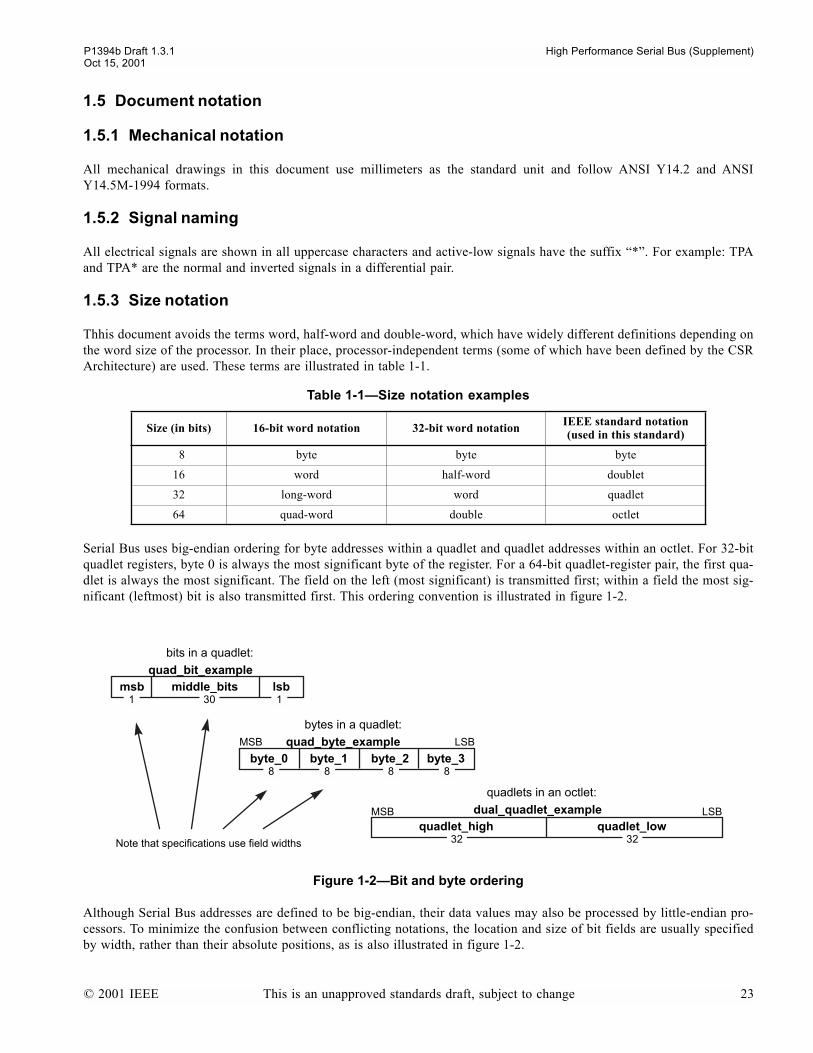
P1394b Draft 1.3.1 High Performance Serial Bus (Supplement)Oct 15, 2001
1.5 Document notation
1.5.1 Mechanical notation
All mechanical drawings in this document use millimeters as the standard unit and follow ANSI Y14.2 and ANSIY14.5M-1994 formats.
1.5.2 Signal naming
All electrical signals are shown in all uppercase characters and active-low signals have the suffix *. For example: TPAand TPA* are the normal and inverted signals in a differential pair.
1.5.3 Size notation
Thhis document avoids the terms word, half-word and double-word, which have widely different definitions depending onthe word size of the processor. In their place, processor-independent terms (some of which have been defined by the CSRArchitecture) are used. These terms are illustrated in table 1-1.
Serial Bus uses big-endian ordering for byte addresses within a quadlet and quadlet addresses within an octlet. For 32-bitquadlet registers, byte 0 is always the most significant byte of the register. For a 64-bit quadlet-register pair, the first qua-dlet is always the most significant. The field on the left (most significant) is transmitted first; within a field the most sig-nificant (leftmost) bit is also transmitted first. This ordering convention is illustrated in figure 1-2.
Although Serial Bus addresses are defined to be big-endian, their data values may also be processed by little-endian pro-cessors. To minimize the confusion between conflicting notations, the location and size of bit fields are usually specifiedby width, rather than their absolute positions, as is also illustrated in figure 1-2.
Table 1-1Size notation examples
Size (in bits) 16-bit word notation 32-bit word notation IEEE standard notation(used in this standard)
8 byte byte byte
16 word half-word doublet
32 long-word word quadlet
64 quad-word double octlet
Figure 1-2Bit and byte ordering
bits in a quadlet:
lsbmsb
bytes in a quadlet:
byte_0
quadlet_high quadlet_low
quadlets in an octlet:
Note that specifications use field widths
MSB LSB
byte_1 byte_2 byte_3
quad_bit_example
quad_byte_example
dual_quadlet_example
middle_bits
MSB LSB
1 30 1
8 8 8 8
32 32
© 2001 IEEE This is an unapproved standards draft, subject to change 23
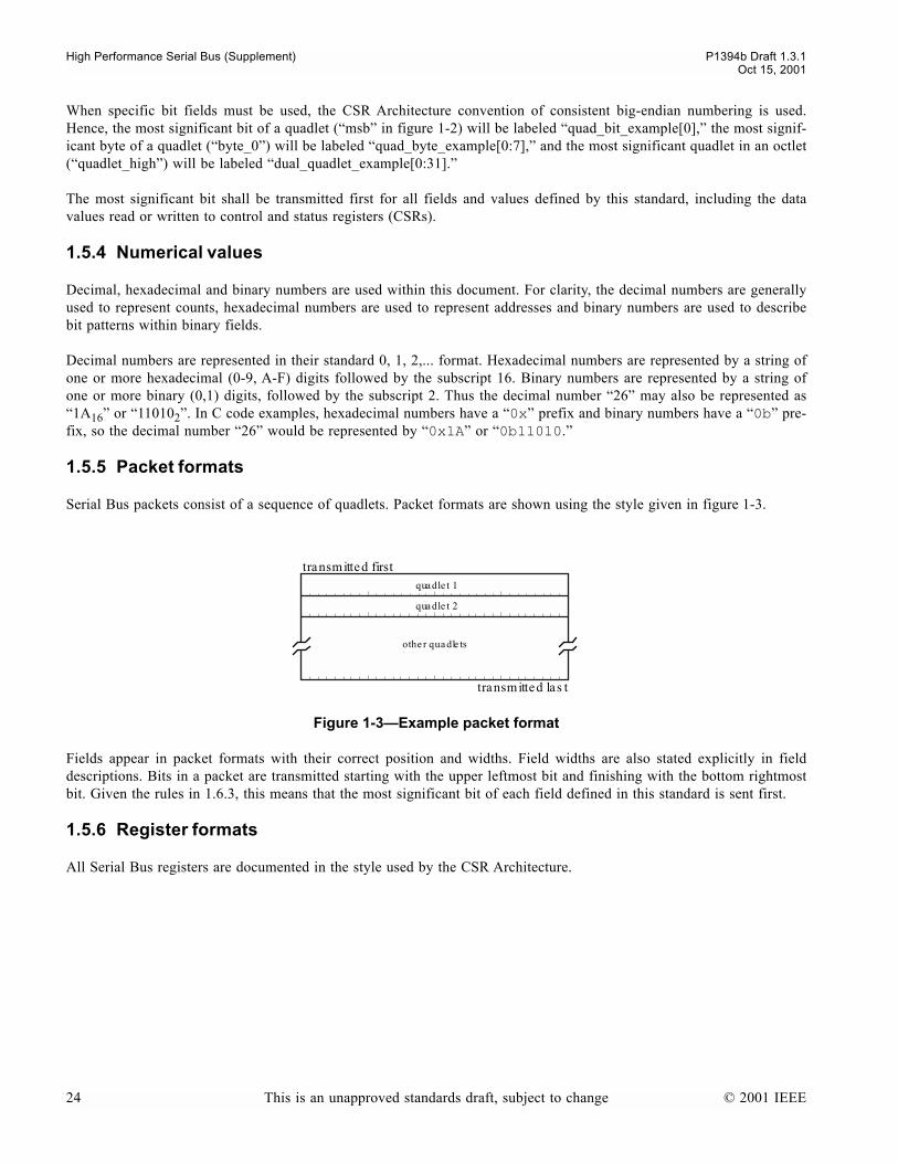
High Performance Serial Bus (Supplement) P1394b Draft 1.3.1
Oct 15, 2001
When specific bit fields must be used, the CSR Architecture convention of consistent big-endian numbering is used.Hence, the most significant bit of a quadlet (msb in figure 1-2) will be labeled quad_bit_example[0], the most signif-icant byte of a quadlet (byte_0) will be labeled quad_byte_example[0:7], and the most significant quadlet in an octlet(quadlet_high) will be labeled dual_quadlet_example[0:31].
The most significant bit shall be transmitted first for all fields and values defined by this standard, including the datavalues read or written to control and status registers (CSRs).
1.5.4 Numerical values
Decimal, hexadecimal and binary numbers are used within this document. For clarity, the decimal numbers are generallyused to represent counts, hexadecimal numbers are used to represent addresses and binary numbers are used to describebit patterns within binary fields.
Decimal numbers are represented in their standard 0, 1, 2,... format. Hexadecimal numbers are represented by a string ofone or more hexadecimal (0-9, A-F) digits followed by the subscript 16. Binary numbers are represented by a string ofone or more binary (0,1) digits, followed by the subscript 2. Thus the decimal number 26 may also be represented as1A16 or 110102. In C code examples, hexadecimal numbers have a 0x prefix and binary numbers have a 0b pre-fix, so the decimal number 26 would be represented by 0x1A or 0b11010.
1.5.5 Packet formats
Serial Bus packets consist of a sequence of quadlets. Packet formats are shown using the style given in figure 1-3.
Fields appear in packet formats with their correct position and widths. Field widths are also stated explicitly in fielddescriptions. Bits in a packet are transmitted starting with the upper leftmost bit and finishing with the bottom rightmostbit. Given the rules in 1.6.3, this means that the most significant bit of each field defined in this standard is sent first.
1.5.6 Register formats
All Serial Bus registers are documented in the style used by the CSR Architecture.
Figure 1-3Example packet format
qua dle t 1
qua dle t 2
transmitted first
transmitted las t
othe r qua dle ts
24 This is an unapproved standards draft, subject to change © 2001 IEEE
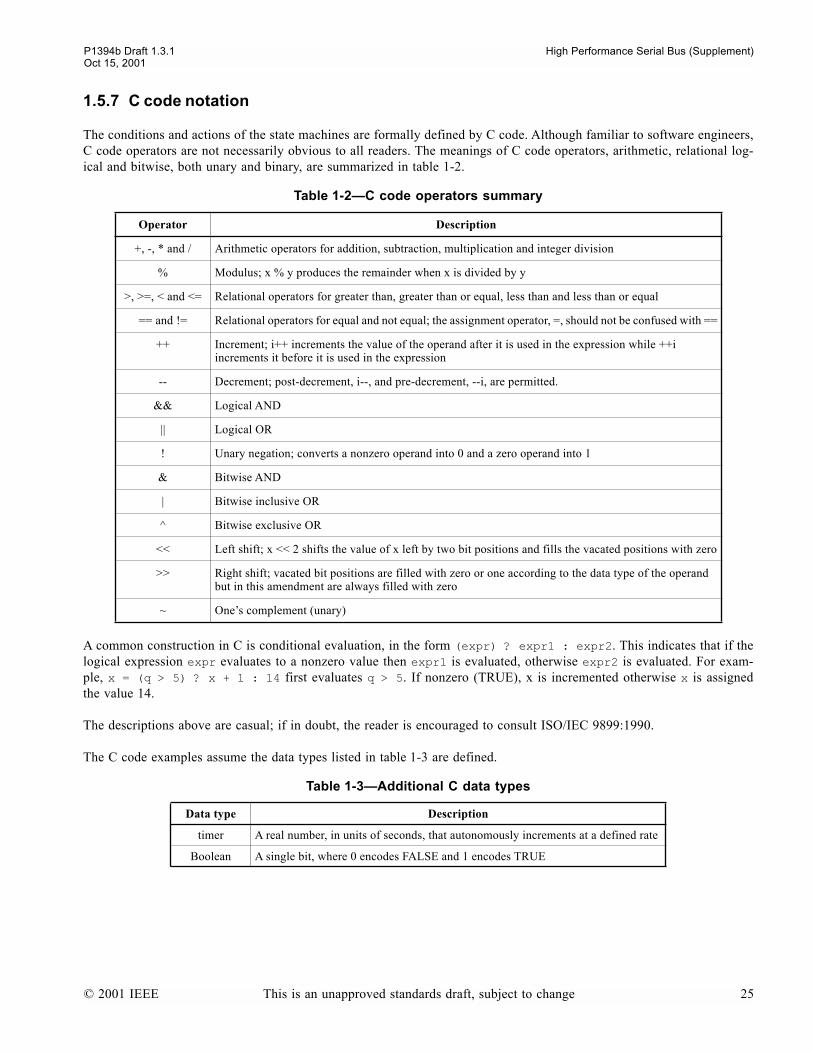
P1394b Draft 1.3.1 High Performance Serial Bus (Supplement)Oct 15, 2001
1.5.7 C code notation
The conditions and actions of the state machines are formally defined by C code. Although familiar to software engineers,C code operators are not necessarily obvious to all readers. The meanings of C code operators, arithmetic, relational log-ical and bitwise, both unary and binary, are summarized in table 1-2.
A common construction in C is conditional evaluation, in the form (expr) ? expr1 : expr2. This indicates that if thelogical expression expr evaluates to a nonzero value then expr1 is evaluated, otherwise expr2 is evaluated. For exam-ple, x = (q > 5) ? x + 1 : 14 first evaluates q > 5. If nonzero (TRUE), x is incremented otherwise x is assignedthe value 14.
The descriptions above are casual; if in doubt, the reader is encouraged to consult ISO/IEC 9899:1990.
The C code examples assume the data types listed in table 1-3 are defined.
Table 1-2C code operators summary
Operator Description
+, -, * and / Arithmetic operators for addition, subtraction, multiplication and integer division
% Modulus; x % y produces the remainder when x is divided by y
>, >=, < and <= Relational operators for greater than, greater than or equal, less than and less than or equal
== and != Relational operators for equal and not equal; the assignment operator, =, should not be confused with ==
++ Increment; i++ increments the value of the operand after it is used in the expression while ++i increments it before it is used in the expression
-- Decrement; post-decrement, i--, and pre-decrement, --i, are permitted.
&& Logical AND
|| Logical OR
! Unary negation; converts a nonzero operand into 0 and a zero operand into 1
& Bitwise AND
| Bitwise inclusive OR
^ Bitwise exclusive OR
<< Left shift; x << 2 shifts the value of x left by two bit positions and fills the vacated positions with zero
>> Right shift; vacated bit positions are filled with zero or one according to the data type of the operand but in this amendment are always filled with zero
~ Ones complement (unary)
Table 1-3Additional C data types
Data type Description
timer A real number, in units of seconds, that autonomously increments at a defined rate
Boolean A single bit, where 0 encodes FALSE and 1 encodes TRUE
© 2001 IEEE This is an unapproved standards draft, subject to change 25
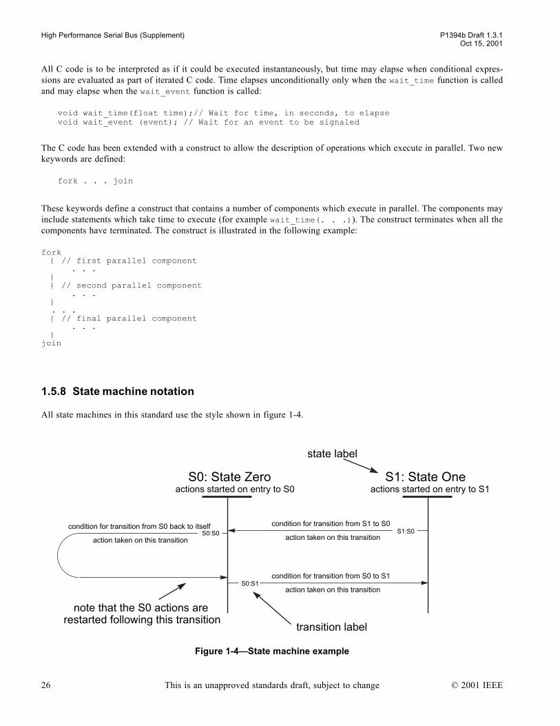
High Performance Serial Bus (Supplement) P1394b Draft 1.3.1
Oct 15, 2001
All C code is to be interpreted as if it could be executed instantaneously, but time may elapse when conditional expres-sions are evaluated as part of iterated C code. Time elapses unconditionally only when the wait_time function is calledand may elapse when the wait_event function is called:
void wait_time(float time);// Wait for time, in seconds, to elapsevoid wait_event (event); // Wait for an event to be signaled
The C code has been extended with a construct to allow the description of operations which execute in parallel. Two newkeywords are defined:
fork . . . join
These keywords define a construct that contains a number of components which execute in parallel. The components mayinclude statements which take time to execute (for example wait_time(. . .)). The construct terminates when all thecomponents have terminated. The construct is illustrated in the following example:
fork // first parallel component . . . // second parallel component . . . . . . // final parallel component . . . join
1.5.8 State machine notation
All state machines in this standard use the style shown in figure 1-4.
Figure 1-4State machine example
condition for transition from S0 to S1
S1: State Oneactions started on entry to S1
condition for transition from S1 to S0
S0: State Zeroactions started on entry to S0
S1:S0
S0:S1
transition label
state label
action taken on this transition
note that the S0 actions are restarted following this transition
action taken on this transition
action taken on this transition
S0:S0condition for transition from S0 back to itself
26 This is an unapproved standards draft, subject to change © 2001 IEEE
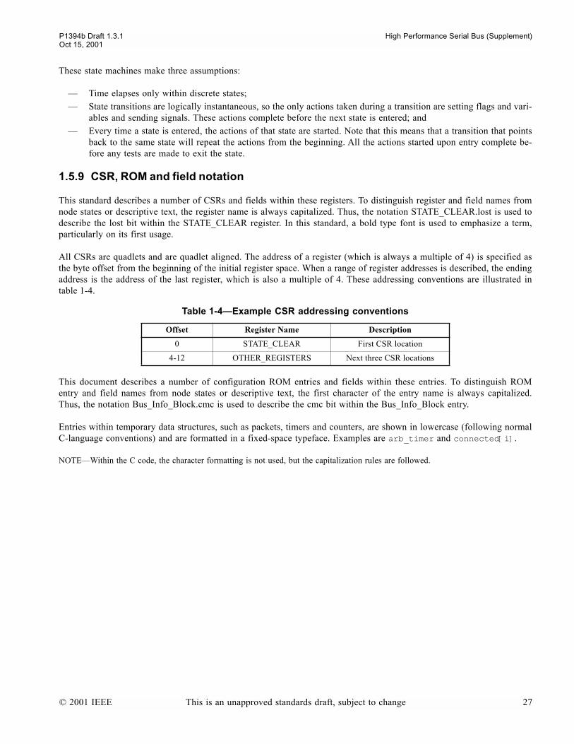
P1394b Draft 1.3.1 High Performance Serial Bus (Supplement)Oct 15, 2001
These state machines make three assumptions:
Time elapses only within discrete states; State transitions are logically instantaneous, so the only actions taken during a transition are setting flags and vari-
ables and sending signals. These actions complete before the next state is entered; and Every time a state is entered, the actions of that state are started. Note that this means that a transition that points
back to the same state will repeat the actions from the beginning. All the actions started upon entry complete be-fore any tests are made to exit the state.
1.5.9 CSR, ROM and field notation
This standard describes a number of CSRs and fields within these registers. To distinguish register and field names fromnode states or descriptive text, the register name is always capitalized. Thus, the notation STATE_CLEAR.lost is used todescribe the lost bit within the STATE_CLEAR register. In this standard, a bold type font is used to emphasize a term,particularly on its first usage.
All CSRs are quadlets and are quadlet aligned. The address of a register (which is always a multiple of 4) is specified asthe byte offset from the beginning of the initial register space. When a range of register addresses is described, the endingaddress is the address of the last register, which is also a multiple of 4. These addressing conventions are illustrated intable 1-4.
This document describes a number of configuration ROM entries and fields within these entries. To distinguish ROMentry and field names from node states or descriptive text, the first character of the entry name is always capitalized.Thus, the notation Bus_Info_Block.cmc is used to describe the cmc bit within the Bus_Info_Block entry.
Entries within temporary data structures, such as packets, timers and counters, are shown in lowercase (following normalC-language conventions) and are formatted in a fixed-space typeface. Examples are arb_timer and connected[i].
NOTEWithin the C code, the character formatting is not used, but the capitalization rules are followed.
Table 1-4Example CSR addressing conventions
Offset Register Name Description
0 STATE_CLEAR First CSR location
4-12 OTHER_REGISTERS Next three CSR locations
© 2001 IEEE This is an unapproved standards draft, subject to change 27

High Performance Serial Bus (Supplement) P1394b Draft 1.3.1Oct 15, 2001
1.5.10 Register specification format
This document defines the format and function of Serial Bus-specific CSRs. Registers may be read only, write only orboth readable and writable. The same distinctions may apply to any field within a register. A CSR specification includesthe format (the sizes and names of bit field locations), the initial value of the register, the value returned when the registeris read and the effect(s) when the register is written. An example register is illustrated in figure 1-5.
The register definition lists the names of register fields. These names are descriptive, but the fields are defined in the text;their function should not be inferred solely from their names. However, the register definition fields in figure 1-5 have themeanings specified by table 1-5.
A nodes CSRs shall be initialized when power is restored (power reset) and may be initialized when a bus reset occursor a quadlet is written to the nodes RESET_START register (command reset). If a CSRs bus reset or command resetvalues differ from its initial values, they shall be explicitly specified.
The read value fields in figure 1-5 have the meanings specified by table 1-6.
Figure 1-5CSR format specification (example)
Table 1-5Register definition fields
Name Abbreviation Definition
unit dependent unit_depend The meaning of this field shall be defined by the unit architecture(s) of the node.
vendor dependent vendor_depend The meaning of this field shall be defined by the vendor of the node.
Within a unit architecture, the unit-dependent fields may be defined to be vendor dependent.
Table 1-6Read value fields
Name Abbreviation Definition
last write w The value of the data field shall be the value that was previously written to the same register address.
last update u The value of the data field shall be the last value that was updated by node hardware.
unit_depend vendor dependent resvsig why not
unit_depend zeros 01 0 0
last write last update 0w u u
stored ignored is i e
definition
initial value
read value
write effect
12 16 1 1 1 1
28 This is an unapproved standards draft, subject to change © 2001 IEEE
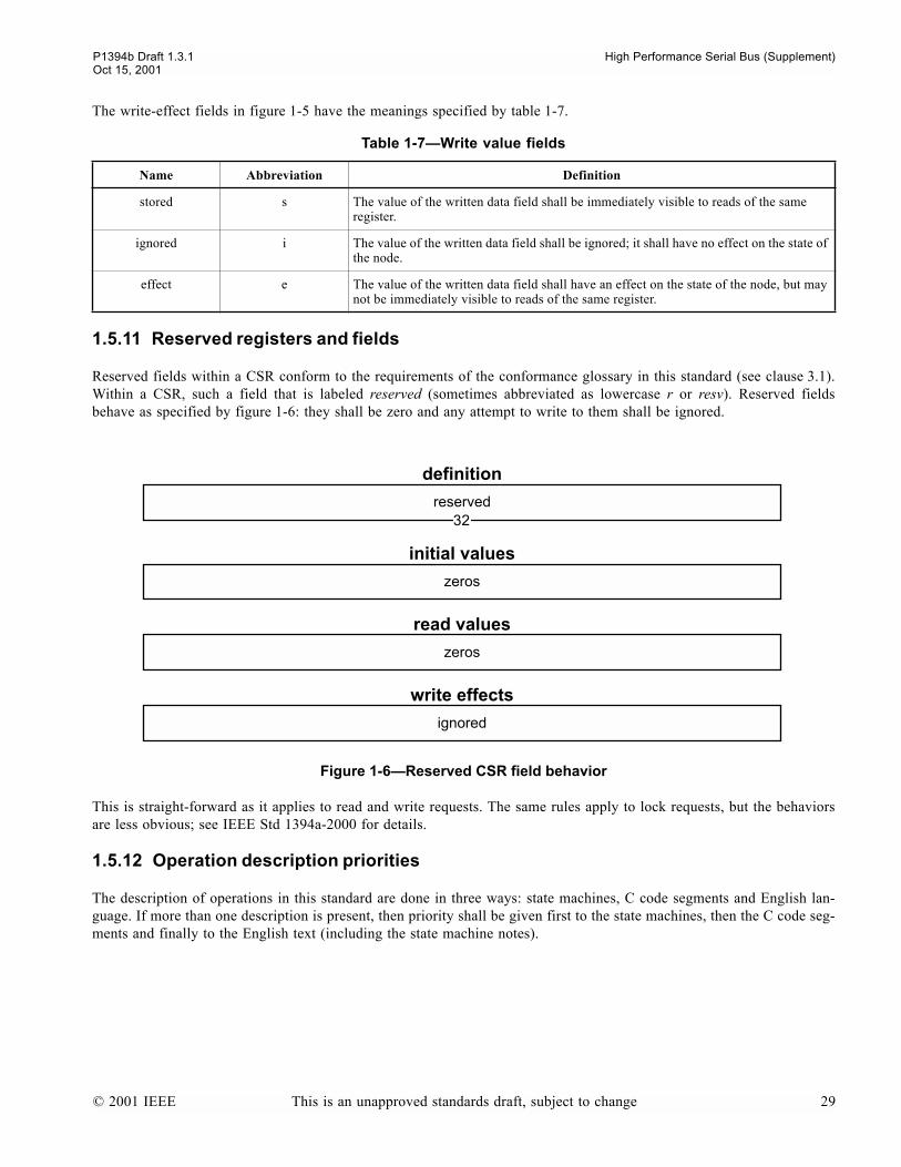
P1394b Draft 1.3.1 High Performance Serial Bus (Supplement)Oct 15, 2001
The write-effect fields in figure 1-5 have the meanings specified by table 1-7.
1.5.11 Reserved registers and fields
Reserved fields within a CSR conform to the requirements of the conformance glossary in this standard (see clause 3.1).Within a CSR, such a field that is labeled reserved (sometimes abbreviated as lowercase r or resv). Reserved fieldsbehave as specified by figure 1-6: they shall be zero and any attempt to write to them shall be ignored.
This is straight-forward as it applies to read and write requests. The same rules apply to lock requests, but the behaviorsare less obvious; see IEEE Std 1394a-2000 for details.
1.5.12 Operation description priorities
The description of operations in this standard are done in three ways: state machines, C code segments and English lan-guage. If more than one description is present, then priority shall be given first to the state machines, then the C code seg-ments and finally to the English text (including the state machine notes).
Table 1-7Write value fields
Name Abbreviation Definition
stored s The value of the written data field shall be immediately visible to reads of the same register.
ignored i The value of the written data field shall be ignored; it shall have no effect on the state of the node.
effect e The value of the written data field shall have an effect on the state of the node, but may not be immediately visible to reads of the same register.
Figure 1-6Reserved CSR field behavior
reserved
zeros
zeros
ignored
definition
initial values
read values
write effects
32
© 2001 IEEE This is an unapproved standards draft, subject to change 29

High Performance Serial Bus (Supplement) P1394b Draft 1.3.1Oct 15, 2001
30 This is an unapproved standards draft, subject to change © 2001 IEEE

P1394b Draft 1.3.1 High Performance Serial Bus (Supplement)Oct 15, 2001
2. References
The standards named in this section contain provisions which, through reference in this text, constitute provisions of thisstandard. At the time of publication, the editions indicated were valid. All standards are subject to revision; parties toagreements based on this standard are encouraged to investigate the possibility of applying the most recent editions of thestandards indicated below.
AF-PHY-0015.000 (September, 1994), ATM Physical Medium Dependent Interface Specification for 155 Mb/s over TwistedPair Cable1
ANSI X3.230-1994 (R1999), American National Standard for Information TechnologyFibre ChannelPhysical and Signal-ing Interface (FC-PH)
ANSI X3.263-1995, American National Standard for Information TechnologyFibre Distributed Data Interface (FDDI)Token Ring Twisted Pair Physical Layer Medium Dependent (TP-PMD)
ANSI/EIA 364-C-1-00, Electrical Connector/Socket Test Procedures Including Environmental Classifications2
ANSI/EIA 364-06B-00, Contact Resistance Test Procedure for Electrical ConnectorsANSI/EIA 364-09C-99, Durability Test Procedure for Electrical ConnectorsANSI/EIA 364-13B-98, Mating and Unmating Forces Test Procedure for Electrical ConnectorsANSI/EIA 364-17B-99, Temperature Life with or without Electrical Load Test Procedure for Electrical ConnectorsANSI/EIA 364-18A-84, Visual and Dimensional Inspection Procedure for Electrical ConnectorsANSI/EIA 364-20B-99, Withstanding Voltage Test Procedure for Electrical ConnectorsANSI/EIA 364-21C-00, Insulation Resistance Test Procedure for Electrical Connectors Sockets and Coaxial ContactsANSI/EIA 364-23A-85, Low Level Contact Resistance Test Procedure for Electrical ConnectorsANSI/EIA 364-27B-96, Mechanical Shock (Specified Pulse) Test Procedure for Electrical ConnectorsANSI/EIA 364-28D-99, Vibration Test Procedure for Electrical Connectors and SocketsANSI/EIA 364-31B-00, Humidity Test Procedure for Electrical Connectors and SocketsANSI/EIA 364-32C-00, Thermal Shock (Temperature Cycling) Test Procedure for Electrical Connectors and SocketsANSI/EIA 364-38B-99, Cable Pull-out Test Procedure for Electrical ConnectorsANSI/EIA 364-41C-99, Cable Flexing Test Procedure for Electrical ConnectorsANSI/EIA 364-46A-98, Microsecond Discontinuity Test Procedure for Electrical Connectors, Contacts and SocketsANSI/EIA 364-65A-98, Mixed Flowing GasANSI/EIA 364-102-98, Rise Time Degradation Test Procedure for Electrical Connectors, Sockets, Cable Assemblies or
Interconnection SystemsANSI/EIA 364-103-99, Propagation Delay Test Procedure for Electrical Connectors, Sockets, Cable Assemblies or Inter-
connection Systems
ANSI/TIA/EIA-455-54B-98, Mode Scrambler Requirements for Overfilled Launching Conditions to Multimode Fibers
ANSI/TIA/EIA-455-95A-00, Absolute Optical Power Test for Optical Fibers and Cables
ANSI/TIA/EIA-455-54B-98, Mode Scrambler Requirements for Overfilled Launching Conditions to Multimode Fibers
ANSI/TIA/EIA-455-127-91, Spectral Characterization of Multimode Laser Diodes, Performance of Optical Fibers
ANSI/TIA/EIA-526-14A-98, Optical Power Loss Measurement of Installed Multimode Fiber Cable Plant
ANSI/TIA/EIA-568-A-95, Commercial Building Telecommunications Cabling Standard
1 ATM Forum publications are available from the ATM Forum, 2570 West El Camino Real, Suite 304, Mountain View, CA 94040-1313.They may also be downloaded from http://www.atmforum.com.
2 ANSI publications are availabale from Sales Department, American National Standards Institute, 11 West 42nd Street, 13th Floor, NewYork, NY 10036-8002, USA.
© 2001 IEEE This is an unapproved standards draft, subject to change 31

High Performance Serial Bus (Supplement) P1394b Draft 1.3.1Oct 15, 2001
ANSI/TIA/EIA-604-93, Fiber Optic Connector Intermateability Standards
ASME Y14.2M-1992 (R1998), Line Conventions and Lettering
ASME Y14.5M-1994 (R1999), Dimensioning and Tolerancing
IEC 61000-4-2 (1999-05) Edition 1.1, Electromagnetic compatibility (EMC) - Part 4-2: Testing and measurement techniques -Electrostatic discharge immunity test
IEEE Std 1394-1995, Standard for a High Performance Serial Bus
IEEE Std 1394a-2000, Standard for a High Performance Serial BusAmendment 1
ISO/IEC 9899:1999, Programming languagesC1
ISO/IEC 11801:2000, Information technologyGeneric cabling for customer premises.
This standard shall also be used in conjunction with the following publications under development. When approved as astandard, the approved version shall apply.
IEEE P1212, Draft Standard for a Control and Status Registers (CSR) Architecture for microcomputer buses
NOTEIf, at the time the IEEE Editor prepares this standard for publication, draft standard IEEE P1212 has been approved bythe IEEE-SA Standards Board, the Editor is requested to change the citation to reference the approved standard. Otherwise thecitation should reference IEEE P1212, Draft 1.0, October 18, 1999.
NCITS TR-25-1999 1-SEP-1999 Information Technology - Fibre Channel Methodologies for Jitter Specification2
1 ISO/IEC publications are available from the ISO Central Secretariat, Case Postale 56, 1 rue de Varembé, CH-1211, Genève 20,Switzerland/Suisse. ISO publications are also available in the United States from the American National Standards Institute.
2 NCITS T11.2 working documents are available at http://www.t11.org.
32 This is an unapproved standards draft, subject to change © 2001 IEEE

P1394b Draft 1.3.1 High Performance Serial Bus (Supplement)Oct 15, 2001
3. Definitions and abbreviations
3.1 Conformance glossary
Several keywords are used to differentiate between different levels of requirements and optionally, as follows:
3.1.1 expected: A keyword used to describe the behavior of the hardware or software in the design models assumed by thisstandard. Other hardware and software design models may also be implemented.
3.1.2 ignored: A keyword that describes bits, bytes, quadlets, octlets or fields whose values are not checked by the recipient.
3.1.3 may: A keyword that indicates flexibility of choice with no implied preference.
3.1.4 reserved: A keyword used to describe objectsbits, bytes, quadlets, octlets and fieldsor the code values assigned tothese objects in cases where either the object or the code value is set aside for future standardization. Usage and interpretationmay be specified by future extensions to this or other standards. A reserved object shall be zeroed or, upon development of afuture standard, set to a value specified by such a standard. The recipient of a reserved object shall not check its value. Therecipient of a defined object shall check its value and reject reserved code values.
3.1.5 shall: A keyword indicating a mandatory requirement. Designers are required to implement all such mandatory require-ments to ensure interoperability with other products conforming to this standard.
3.1.6 should: A keyword indicating flexibility of choice with a strongly preferred alternative. Equivalent to the phrase is rec-ommended.
3.2 Technical glossary
The following are terms that are used within this standard:
3.2.1 3B/4B: A line code that maps 3 bit symbols to 4 bit symbols so as to achieve DC balance and bounded disparity. Used tocreate the 8B/10B code.
3.2.2 5B/6B: A line code that maps 5 bit symbols to 6 bit symbols so as to achieve DC balance and bounded disparity. Used tocreate the 8B/10B code.
3.2.3 8B/10B: A line code that maps 8 bit symbols to 10 bit symbols so as to achieve DC balance and bounded disparity.
3.2.4 acknowledge: An acknowledge packet.
3.2.5 acknowledge packet: An 8-bit packet that may be transmitted in response to the receipt of a primary packet. The mostand least significant nibbles are the one's complement of each other.
3.2.6 acronym: A contrived reduction of nomenclature yielding mnemonics (ACRONYM).
3.2.7 active port: A connected, enabled port that is capable of detecting all Serial Bus signal states and participating in thereset, tree identify, self-identify and normal arbitration phases.
3.2.8 arbitration: The process by which nodes compete for control of the bus. Upon completion of arbitration, the winningnode is able to transmit a packet or initiate a short bus reset.
3.2.9 arbitration request: An 8B/10B coded symbol that is sent on a Beta-mode port when it is not transmitting data. An arbi-tration request is used for BOSS arbitration and combines requests for both isochronous and asynchronous packet transmis-sions into a single symbol which, after scrambling, is represented by a single data character.
© 2001 IEEE This is an unapproved standards draft, subject to change 33

High Performance Serial Bus (Supplement) P1394b Draft 1.3.1Oct 15, 2001
3.2.10 arbitration reset: If no node has an asynchronous request for the current fairness interval, then an arbitration reset issignaled to start a new asynchronous arbitration fairness interval. In a Legacy cloud, the reset is signaled by arbitration resetgap. In a B cloud, the reset is signaled by an arbitration reset token.
3.2.11 arbitration reset gap: The period of time on a Legacy bus that indicates the start of a new asynchronous arbitrationfairness interval. An arbitration reset gap is longer than a subaction gap.
3.2.12 arbitration reset indication: An arbitration reset gap in a Legacy cloud or an arbitration reset token in a B cloud.
3.2.13 arbitration reset token: Either of an ASYNC_EVEN or an ASYNC_ODD control token. Sent in a B cloud to indicatethe start of a new asynchronous arbitration fairness interval by changing the phase.
3.2.14 arbitration signaling: In a Legacy cloud, a protocol for the exchange of bidirectional, unclocked signals betweennodes during arbitration. In a B cloud, the exchange of arbitration tokens.
3.2.15 asynchronous packet: A primary packet transmitted in accordance with asynchronous arbitration rules (outside of theisochronous period).
3.2.16 attached peer PHY: A peer cable PHY at the other end of a particular physical connection from the local PHY.
3.2.17 B cloud: A collection of B nodes and/or Border nodes in which all inter-node connections are made through Beta ports.
3.2.18 B link: A link which is capable of operating according to the specifications given in clause 14. or clause 15., and in par-ticular issues requests appropriate to BOSS arbitration.
3.2.19 B bus: An operating bus in which all nodes are operating as B PHYs.
3.2.20 B node. A node whose PHY is operating as a B PHY.
3.2.21 B only PHY: A PHY which is only capable of B PHY mode of operation, i.e. all its ports are Beta-only ports and itslink, if any, is a B link or a PIL.
3.2.22 B-parallel link: A mode of Link operation in which the PHY-Link signalling is provided to the PHY using a parallelinterface.
3.2.23 B PHY: A mode of PHY operation in which all the logically connected ports are operating in Beta mode and the link, ifany, is not configured to operate in Legacy PHY-link mode.
3.2.24 base rate: A data rate of 98.304Mbits/s ± 100 ppm. In a cable environment, all Legacy capable nodes are capable ofcommunicating at this rate and all B capable nodes are capable of communicating at 4 * base rate.
3.2.25 BER: Bit error ratio. The ratio of the number of bits received in error to the total number of bits received.
3.2.26 Beta Mode: When a port is operating according to the specifications given in clauses 10., 11. and 13. and, in particular,is using the 8B/10B symbol coding and obeying the BOSS arbitration protocols then the port is in Beta Mode. The speed of aport sending in Beta Mode is denoted by the β suffix (e.g., S400β)
3.2.27 Beta port: A port that is operating in Beta Mode.
3.2.28 Beta-only port: A port that is only capable of operating as a Beta port.
3.2.29 bilingual port: A port that is capable of operating both as a Beta port and as a DS port. The mode of operation is deter-mined at the time that the logical connection is made and depends on the capabilities of the peer port.
34 This is an unapproved standards draft, subject to change © 2001 IEEE

P1394b Draft 1.3.1 High Performance Serial Bus (Supplement)Oct 15, 2001
3.2.30 Border node: A node with both (i) either its link operating as a B link or at least one Beta port or both, and (ii) either its link operating as a Legacy link or at least one DS port or both.
3.2.31 BOSS: An acronym for Bus Owner/Supervisor/Selector. In a B cloud, the BOSS is the node currently responsible fortaking arbitration decisions. A node becomes BOSS by virtue of being the last node to transmit data in a subaction (in general,this is the node transmitting an acknowledge to a non-broadcast asynchronous packet, or the primary packet transmitter in allother cases), or by receiving a grant. The BOSS determines the end of the fairness interval and the end of isochronous inter-vals, notifying the other nodes. Finally, the BOSS selects the path to grant next, thereby passing the BOSS rights and responsi-bilities to another node.
3.2.32 BOSS arbitration: The arbitration scheme defined by this standard. The principle features of BOSS arbitration are thatthe node making the arbitration decision varies (see BOSS), and that arbitration requests may be overlapped with data trans-mission and both isochronous and asynchronous requests may be pipelined for the succeeding isochronous interval or fairnessinterval respectively.
3.2.33 bus ID: A 10-bit number uniquely specifying a particular bus within a system of multiple interconnected buses.
3.2.34 byte: Eight bits of data.
3.2.35 cable PHY: Abbreviation for the cable physical layer.
3.2.36 cable physical layer: The version of the physical layer applicable to the Serial Bus cable environment.
3.2.37 CAT-5: Category 5 UTP cable.
3.2.38 character: A 10-bit sequence of data sent on a connection that is operating in B mode.
3.2.39 comma character: See comma sequence.
3.2.40 comma sequence: A bit sequence that defines boundaries for byte synchronization.
3.2.41 concatenated transaction: A split transaction comprised of concatenated subactions.
3.2.42 configuration request: A configuration request conveys information pertaining to the configuration of the bus or toprovide support for non-BOSS style arbitration. A configuration request is encoded into a single symbol which, after scram-bling, is represented by a data character.
3.2.43 connected PHY: A peer cable PHY at the other end of a particular physical connection from the local PHY.
3.2.44 connection: Two ports that can communicate with each other and the media between those two ports.
3.2.45 connection attenuation: The static loss of a connection between a transmitter and receiver. It includes the loss of thefiber, connectors, and splices.
3.2.46 connection penalties: The power penalties of a connection not attributed to connection attenuation. It includes modalnoise, RIN, ISI, mode partition noise, extinction ratio, and eye opening penalties.
3.2.47 connection tone: Signal used to indicate that a port is capable of operating in Beta mode. Also confirms that a connec-tion exists between two Beta-mode capable ports.
3.2.48 control character: A 10-bit character used to convey control information. Control characters are distinguishable fromdata characters in that they are not 8B/10B characters. Each control character has zero disparity.
© 2001 IEEE This is an unapproved standards draft, subject to change 35

High Performance Serial Bus (Supplement) P1394b Draft 1.3.1Oct 15, 2001
3.2.49 CSR Architecture: ISO/IEC 13213:1994 [ANSI/IEEE Std 1212, 1994 Edition], Information technology-Microproces-sor systems-Control and Status Registers (CSR) Architecture for microcomputer buses.
3.2.50 cycle master: The node that generates the periodic cycle start packet 8000 times a second.
3.2.51 cycle start: Synonymous with cycle start packet.
3.2.52 cycle start packet: A primary packet sent by the cycle master that indicates the start of an isochronous interval.
3.2.53 data bit: The smallest signaling element used by the physical layer for transmission of packet data on the medium.
3.2.54 data character: A character used by the 8B/10B code.
3.2.55 Data Strobe (DS): A signaling method using two signals in which one signal (Data) always indicates the binary valueof the data (0 or 1) and the other signal (Strobe) changes if the data stays the same during successive bit cells. This signalingmethod is used in IEEE Std 1394-1995 and IEEE Std 1394a-2000.
3.2.56 DC balance: The requirement that over long runs of binary symbols there be no net disparity.
3.2.57 destination: A node that is addressed by a packet. If the destination is individually addressed by a source, then it has toreturn an acknowledge packet.
3.2.58 disabled port: A port configured to neither transmit, receive or repeat Serial Bus signals. A disabled port shall bereported as disconnected in a PHY's self-ID packet(s).
3.2.59 disconnected port: A port whose connection detect circuitry detects no peer PHY at the other end of a cable.
3.2.60 disparity: The number of ones in a transmission character minus the number of zeros in a character.
3.2.61 dispersion slope: The rate of change of the chromatic dispersion of a fiber with wavelength.
3.2.62 doublet: Two bytes, or 16 bits of data.
3.2.63 DS mode: The form of electrical signaling and handshaking that is compatible with IEEE Std 1394-1995 and IEEEStd 1394a-2000.
3.2.64 DS only port: A port only capable of operating as a DS port.
3.2.65 DS port: A port that is operating according to Legacy specifications, in particular using DS electrical signaling andobeying the arbitration protocols defined therein. A DS only port or a bilingual port can operate as a DS port.
3.2.66 EIA: Electronic Industries Association.
3.2.67 extinction ratio: The ratio of the average optical power representing a logical one to the average optical power repre-senting a logical zero measured when transients have settled.
3.2.68 eye diagram: Oscilloscope display of the physical layer signal which is triggered on a bit edge and shows many differ-ent bit patterns overlaid on top of each other.
3.2.69 fairness interval: A time period delimited by arbitration reset indicators. Within a fairness interval, the total number ofasynchronous packets that may be transmitted by a node is limited. Each node's limit may be explicitly established by the busmanager or it may be implicit.
3.2.70 fiber attenuation: The static loss per unit length of the fiber at a particular wavelength, usually expressed in dB/km.
36 This is an unapproved standards draft, subject to change © 2001 IEEE

P1394b Draft 1.3.1 High Performance Serial Bus (Supplement)Oct 15, 2001
3.2.71 FOP: A fanout PHY. A multi-ported PHY that is attached to a PIL using the serial interface defined in clause 15.
3.2.72 FWHM: Full Width Half Maximum.
3.2.73 galvanic isolation: A mechanism to avoid low frequency ground loop currents.
3.2.74 gap: A period of idle bus.
3.2.75 GOF: Glass Optical Fiber.
3.2.76 Hybrid bus: An operating bus that contains at least one Border node.
3.2.77 IEC: International Electrotechnical Commission.
3.2.78 initial node space: The 256 terabytes of Serial Bus address space that is available to each node. Addresses within ini-tial node space are 48 bits and are based at zero. The initial node space includes initial memory space, private space, initial reg-ister space and initial units space. See either ISO/IEC 13213:1994 or IEEE Std 1394-1995 for more information on addressspaces.
3.2.79 initial register space: A 2048 byte portion of initial node space with a base address of FFFF F00016. This addressspace is reserved for resources accessible immediately after a bus reset. Core registers defined by ISO/IEC 13213:1994 arelocated within initial register space as are Serial Bus-dependent registers defined by IEEE Std 1394-1995.
3.2.80 initial units space: A portion of initial node space with a base address of FFFF F000 80016 This places initial unitsspace adjacent to and above initial register space. The CSR's and other facilities defined by unit architectures are expected tolie within this space.
3.2.81 ISO: International Organization for Standardization.
3.2.82 isochronous: Uniform in time (i.e., having equal duration) and recurring at regular intervals.
3.2.83 isochronous gap: On a Legacy bus, the period of idle bus following an isochronous subaction that precedes asynchro-nous arbitration.
3.2.84 isochronous interval: A period that begins after a cycle start packet is sent and ends with a subaction indication. Dur-ing an isochronous interval, only isochronous subactions may occur. An isochronous interval begins, on average, every 125 µs.
3.2.85 isochronous resource manager: A node that implements the BUS_MANAGER_ID, BANDWIDTH_AVAILABLE,CHANNELS_AVAILABLE and BROADCAST_CHANNEL registers (some of which permit the cooperative allocation ofisochronous resources). Subsequent to each bus reset, one isochronous resource manager is selected from all nodes capable ofthis function.
3.2.86 isochronous subaction: Within the isochronous interval, either a concatenated packet or a packet and the gap that pre-ceded it.
3.2.87 isolated node: A node without active ports; the node's ports may be disabled, disconnected or suspended in any combi-nation.
3.2.88 jitter: Any variation in the zero-crossing time from the ideal bit pattern.
3.2.89 junior border: Any border node in a B cloud except the senior border.
3.2.90 K-code: An 8B/10B symbol that represents control information.
3.2.91 LED: Light Emitting Diode.
© 2001 IEEE This is an unapproved standards draft, subject to change 37

High Performance Serial Bus (Supplement) P1394b Draft 1.3.1Oct 15, 2001
3.2.92 Legacy: Characteristics or behavior of a link, node, PHY, cable or connector defined by IEEE Std 1394-1995 or IEEEStd 1394a-2000.
3.2.93 Legacy cloud: A collection of Legacy nodes and/or Border nodes in which all inter-node connections are made throughLegacy ports.
3.2.94 Legacy request: A request type defined by this specification that is originated by a border node on behalf of a Legacylink or a DS port.
3.2.95 link: Abbreviation for the link layer. Also, the physical entity that implements the link layer. Also, one of the compo-nents connected to the PHY-link interface.
3.2.96 link layer: The Serial Bus protocol layer that provides confirmed and unconfirmed transmission or reception of pri-mary packets.
3.2.97 local root: A unique node in a B cloud - either the root or, if the cloud does not contain the root, the senior border.
3.2.98 logically connected port: A port whose connected status is TRUE. If a port is physically connected to a peer whichis not powered then the port is not logically connected.
3.2.99 low-power connection signaling: Signaling, based on the exchange of very low duty cycle tones, by which the con-nectivity status of a port is determined. This takes place when the port is not active or is disabled.
3.2.100 MMF: Multi-mode fiber.
3.2.101 modal bandwidth: The bandwidth of a multi-mode fiber due to dispersion caused by variations in speed of the prop-agating modes.
3.2.102 mode partition noise: Amplitude, frequency and phase noise in the detected optical signal due to the interaction ofthe modes of a multimode laser and the optical dispersion of the connection.
3.2.103 module: The smallest component of physical management; i.e., a replaceable device.
3.2.104 NA: Numerical Aperture.
3.2.105 nephew node: A node with one port in standby and all other ports (if any) disabled, disconnected or suspended. Thepeer uncle node proxies for the nephew node during bus resets.
3.2.106 Near-End Cross-Talk (NEXT): The noise induced in the receiving pair due to the signal on the transmitting pair onthe same port. For example, the signal on the TpB pair can cause NEXT on the TpA pair of a port.
3.2.107 node: A Serial Bus device that may be addressed independently of other nodes. A minimal node consists of only aPHY without an enabled link. If the link and other layers are present and enabled they are considered part of the node.
3.2.108 node controller: A component within a node that provides a coordination point for management functions exclusivelylocal to a given node and involving the application, transaction, link and physical elements located at that node.
3.2.109 node ID: A 16-bit number that uniquely differentiates a node from all other nodes within a group of interconnectedbuses. The 10 most significant bits of node ID are the same for all nodes on the same bus; this is the bus ID. The six least-sig-nificant bits of node ID are unique for each node on the same bus; this is called the physical ID. The physical ID is assigned asa consequence of bus initialization.
3.2.110 non-return to zero: (NRZ): A signaling technique in which a polarity level high represents a logical 1 (one) and apolarity level low represents a logical level 0 (zero).
38 This is an unapproved standards draft, subject to change © 2001 IEEE

P1394b Draft 1.3.1 High Performance Serial Bus (Supplement)Oct 15, 2001
3.2.111 null packet: A packet in which no data is transmitted.
3.2.112 octlet: Eight bytes, or 64 bits, of data.
3.2.113 overfilled launch: The overfilled launch condition that excites both radial and azimuthal modes defined in TIA/EIA -455 - 54A.
3.2.114 operating speed: Nominal speed at which a port operating in Beta mode is communicating clocked information withits peer, measured in MBits/s (before 8B/10B encoding), usually identified with the S notation (e.g. S100, S200, S400, etc.).
3.2.115 optical power budget: The minimum optical power available to overcome the sum of attenuation plus power penal-ties of the optical path between the transmitter and receiver calculated as the difference between the transmitter launch power(min.) and the receive sensitivity (min.).
3.2.116 originating port: A transmitting port on a PHY which has no active receiving port. The source of the transmittedpacket is either the PHY's local link or the PHY itself.
3.2.117 packet: a sequence of zero or more bits transmitted on Serial Bus and delimited by packet start symbol and a packetend symbol.
3.2.118 packet delimiter: Sequence of control symbols which delineate the beginning and ending of a data packet.
3.2.119 packet speed: The data rate of a packet (necessarily less than or equal to the operating speed of a Beta-mode connec-tion used to transmit the packet).
3.2.120 padding: Symbols inserted between data symbols in a packet to allow slower speed data to be transmitted on a higherspeed connection.
3.2.121 path: The concatenation of all the physical connections between the link layers of two nodes.
3.2.122 payload: The portion of a primary packet that contains data defined by an application.
3.2.123 PCB: Printed circuit board.
3.2.124 peer: Service layer on a remote node at the same level. For instance a peer link layer is the link layer on a differentnode.
3.2.125 PIL: PHY integrated with Link. A link that uses a modified Beta port to attach to a fanout PHY using the protocolsdefined in clause 15.
3.2.126 PHY packet: A 64-bit packet where the most significant 32 bits are the one's complement of the least significant 32bits.
3.2.127 physical connection: The full-duplex physical layer association between directly connected nodes. In the case of thecable physical layer, this is a pair of physical connections running in opposite directions.
3.2.128 physical ID: The least-significant six bits of the node ID. On a particular bus, each node's physical ID is unique.
3.2.129 physical layer (PHY): The Serial Bus protocol layer that translates the logical symbols used by the link layer intoelectrical signals on Serial Bus media. The physical layer is self-initializing. Physical layer arbitration guarantees that only onenode at a time is sending data. The mechanical interface is defined as part of the physical layer. There are different physicallayers for the backplane and for the cable environment.
3.2.130 physical link: In the cable physical layer, the simplex path from the transmit function of the port of one node to thereceive function of a port of a directly connected node.
© 2001 IEEE This is an unapproved standards draft, subject to change 39

High Performance Serial Bus (Supplement) P1394b Draft 1.3.1Oct 15, 2001
3.2.131 ping: A term used to describe the transmission of a PHY packet to a particular node in order to time the responsepacket(s) provoked.
3.2.132 PLL: Phase Locked Loop.
3.2.133 PMD: Physical Medium Dependent.
3.2.134 PMD interface: The part of an interface that is specific to single kind of interconnect.
3.2.135 POF: Plastic Optical Fiber.
3.2.136 Point-to-point (P2P) Packet: Special packet type that is sent on the PIL-FOP interface. This packet is used to carrydata that cannot be sent as part of a normal Serial Bus packets.
3.2.137 port: The part of the PHY that allows connection to one other node.
3.2.138 port state machine: The logic that controls the functioning of a port.
3.2.139 primary packet: Any packet that is not an acknowledge or a PHY packet. A primary packet is an integral number ofquadlets and contains a transaction code in the first quadlet.
3.2.140 proxy_root: In a B-only bus, the root. In a hybrid bus where the root is in a B cloud, the senior border in the B cloudcontaining the root. If the root is a Legacy node, then there is no proxy root.
3.2.141 quadlet: Four bytes, or 32 bits, of data.
3.2.142 random jitter: Jitter that comes from random sources. Characterized by gaussian statistics and unbounded variationaccording to the gaussian distribution function.
3.2.143 receiver eye opening: The interval in time within a bit period where the sampled data value will have a probability oferror less than the specified bit error ratio (BER).
3.2.144 register: A term used to describe addresses that may be read or written by Serial Bus transactions. In the context ofthis standard, the use of the term register does not imply a specific hardware implementation. For example, in the case of splittransactions that permit sufficient time between the request and response subactions, the behavior of the register may be emu-lated by a processor within the module.
3.2.145 repeating port: A transmitting port on a PHY that is repeating a packet from the PHY's receiving port.
3.2.146 request: A primary packet (with optional data) sent by one node's link (the requester) to another node's link (theresponder).
3.2.147 request type: An 8B/10B data character which connotes either an arbitration or configuration request.
3.2.148 response: A primary packet (with optional data) sent in response to a request subaction.
3.2.149 restore: The process of causing a connection in standby to return to the active state.
3.2.150 resume signal : A signal requiring the port to resume normal operations.
3.2.151 resuming port: A previously suspended port which has observed signaling other than the connection tone or has beeninstructed to resume. In either case, the resuming port engages in a protocol with its connected peer PHY in order to reestab-lish normal operations and become active.
3.2.152 RIN: Relative intensity noise. The ratio of the variance in the optical power to the average optical power.
40 This is an unapproved standards draft, subject to change © 2001 IEEE
P1394b Draft 1.3.1 High Performance Serial Bus (Supplement)Oct 15, 2001
3.2.153 RMS Spectral Width: The optical wavelength range as measured by TIA/EIA - 45.5 - 127.
3.2.154 radial overfilled launch: A launch condition created when a multi-mode optical fiber is illuminated by the coherentoptical output of a source operating in its lowest order transverse mode in a manner that excites predominantly the radialmodes of the multi-mode fiber.
3.2.155 run length: The length of a sequence of bits that have the same value, e.g., 1's or 0's.
3.2.156 running digital sum: The number of ones in a character stream minus the number of zeros in a character stream.
3.2.157 running disparity: An estimate of the running digital sum at the end of a character sub-block, based upon the mostrecently transmitted (or received) character sub-block. When initialized with the same value, the running disparity and runningdigital sum will be equal at the end of any character sub-block. Errors in a received character stream may result in the runningdisparity being not equal to the running digital sum.
3.2.158 scrambler: Transmitted signals are chosen from the set of all possible symbols by using both the desired symbol anda pseudo-randomly generated offset pointer. Used to average out the spectral content of the transmitted signal to avoid strongspectral lines.
3.2.159 senior border: A unique border node in a B cloud. The senior border has the highest node_ID of all border nodes inthe cloud, and is responsible for ensuring that certain Legacy gap timings are observed.
3.2.160 self-ID packet: A PHY packet transmitted by a cable PHY during the self-ID phase or in response to a PHY pingpacket.
3.2.161 Serial Bus management: The set of protocols, services and operating procedures that monitors and controls the vari-ous Serial Bus layers - physical, link and transaction.
3.2.162 services: A set of capabilities provided by one protocol layer entity for use by a higher layer or by management enti-ties.
3.2.163 SMF: Single mode fiber.
3.2.164 source: A node that initiates a bus transfer.
3.2.165 speed code: The code used to indicate bit rates for Serial Bus.
3.2.166 split transaction: A transaction where unrelated subactions may take place on the bus between its request andresponse subactions.
3.2.167 STP: Shielded, twisted pair.
3.2.168 standby: A low-power state of a Beta connection in which only low-power connection signaling takes place. No busreset is generated as a result of a port entering or leaving the standby state.
3.2.169 standby initiator: An active port that transmits the STANDBY configuration request and engages in a protocol withits connected peer PHY to place the connection into the standby state.
3.2.170 subaction: A complete link layer operation minimally consisting of a packet transmission. The packet may be option-ally preceded with bus arbitration and optionally followed by an acknowledgment.
3.2.171 subaction gap: In a Legacy cloud, period of idle bus that precedes arbitration for an asynchronous subaction.
3.2.172 subaction indication: A subaction gap or, in a B cloud, an ASYNC_EVEN/ODD control token of the current phase.
© 2001 IEEE This is an unapproved standards draft, subject to change 41
High Performance Serial Bus (Supplement) P1394b Draft 1.3.1Oct 15, 2001
3.2.173 suspend: To go into a low-power mode of operation while maintaining low-power connection signaling. When a portenters or leaves the suspend state a bus reset is generated.
3.2.174 suspend initiator: An active port that transmits the SUSPEND configuration request or the TX_SUSPEND signaland engages in a protocol with its connected peer PHY to place the connection in the suspend state.
3.2.175 suspend target: An active port that receives the SUSPEND configuration request or observes the RX_SUSPEND sig-nal. A suspend target requests that all of the other active ports on the PHY become suspend initiators while the suspend targetport engages in a protocol with its connected peer PHY to suspend the connection.
3.2.176 suspended node: An isolated node with at least one port that is suspended.
3.2.177 suspended port: A connected port not operational for normal Serial Bus arbitration but otherwise capable of detect-ing either a physical cable disconnection or a resume signal.
3.2.178 synchronization: The process of aligning the receiver's circuits to properly detect received bits and to properly detectsymbol boundaries.
3.2.179 TDR: Time Domain Reflectometry.
3.2.180 TIA: Telecommunications Industry Association.
3.2.181 transaction: A request and the optional, corresponding response.
3.2.182 transaction layer: The Serial Bus protocol layer that defines a request-response protocol for read, write and lockoperations.
3.2.183 transmitting port: Any port transmitting clocked data or an arbitration state. A transmitting port is further character-ized as either originating or repeating.
3.2.184 uncle node: A node which proxies for a peer nephew node while the connection between the two is in standby.
3.2.185 unit: A component of a Serial Bus node that provides processing, memory, I/O or some other functionality. Once thenode is initialized, the unit provides a CSR interface. A node may have multiple units, which normally operate independentlyof each other.
3.2.186 unit architecture: The specification document that describes the interface to and the behaviors of a unit implementedwithin a node.
3.2.187 unit interval: The nominal amount of time 1 bit takes to transmit.
3.2.188 UTP: Unshielded Twisted Pair.
3.2.189 VCSEL: Vertical Cavity Surface Emitting Laser.
3.2.190 zero dispersion wavelength: That wavelength where the chromatic dispersion of a fiber is at its minimum.
42 This is an unapproved standards draft, subject to change © 2001 IEEE
P1394b Draft 1.3.1 High Performance Serial Bus (Supplement)Oct 15, 2001
4. Summary description
This is a supplement to IEEE Std 1394-1995 as ammended by IEEE Std 1394a-2000. This standard defines mechanismsthat increase the data rate and the transmission distance for 1394.
4.1 The relationship to IEEE Std 1394a-2000
IEEE Std 1394a-2000 improves many areas of IEEE Std 1394-1995. Of particular note is the improvement in bus effi-ciency. IEEE Std 1394a-2000 provides arbitration acceleration, improves the speed of bus resets, and adds Sus-pend/Resume power management capabilities to the bus. This standard is fully interoperable with IEEE Std 1394a-2000and IEEE Std 1394-1995 at the signaling level of the 6-pin and 4-pin connectors specified therein. This standard supportsthe Data/Strobe form of signaling used in IEEE Std 1394a-2000 and IEEE Std 1394-1995 while adding a new form of sig-naling capable of much higher data rates between Beta-mode ports. This standard also supports new media such as CAT-5 unshielded twisted pairs, glass optical fiber, and plastic optical fiber.
4.2 Faster and further
This standard supports the regular Data/Strobe signaling modes and speeds of IEEE Std 1394-1995. Additionally thisstandard extends bus speeds to S800 and S1600, and has architectural support for S3200 - though there is insufficienttechnical data available at the time of preparation of this standard to specify the signaling parameters for S3200. Silicondevices which support both these modes of signaling are called border nodes since they can signal in two different elec-trical modes.
IEEE Std 1394-1995 recommends a maximum cable length of 4.5 meters. Many applications find this too short a cablerun for their needs. This standard supports optical cable lengths of 50 meters for plastic optical fiber and 100 meters forglass optical fiber. Additionally this standard supports S100 operation over lengths of CAT-5 up to 100 meters. This extrarun length permits new applications for 1394 such as home networking.
© 2001 IEEE This is an unapproved standards draft, subject to change 43
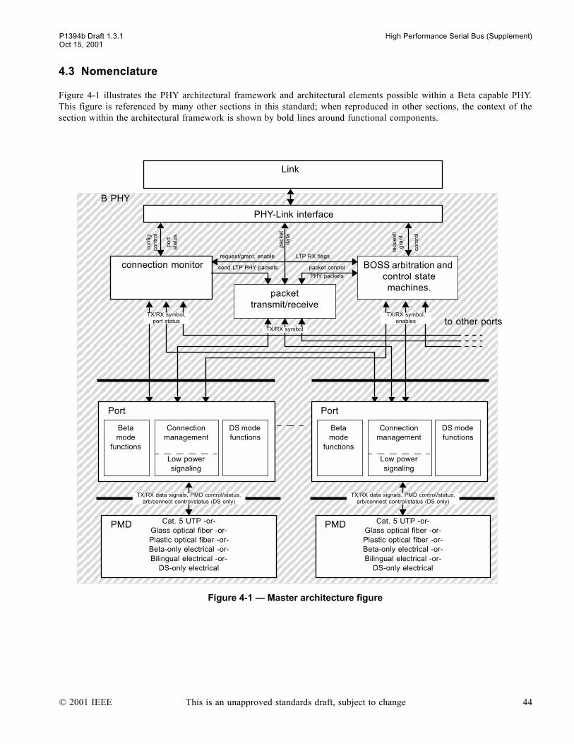
P1394b Draft 1.3.1 High Performance Serial Bus (Supplement)Oct 15, 2001
4.3 Nomenclature
Figure 4-1 illustrates the PHY architectural framework and architectural elements possible within a Beta capable PHY.This figure is referenced by many other sections in this standard; when reproduced in other sections, the context of thesection within the architectural framework is shown by bold lines around functional components.
Figure 4-1 Master architecture figure
BOSS arbitration and control state machines.
Cat. 5 UTP -or-Glass optical fiber -or-Plastic optical fiber -or-Beta-only electrical -or-Bilingual electrical -or-
DS-only electrical
Link
B PHY
PHY-Link interface
packet transmit/receive
connection monitor
DS mode functions
Beta mode
functions
Connection management
Low power signaling
Port
to other ports
pa
cke
t d
ata
send LTP PHY packets
req
ue
st\
gra
nt
packet control
request/grant, enable LTP RX flags
TX/RX symbol,port status
TX/RX symbol
TX/RX symbol,enables
con
tro
l
con
figco
ntr
ol
po
rtst
atu
s
DS mode functions
Beta mode
functions
Connection management
Low power signaling
Port
PHY packets
TX/RX data signals, PMD control/status,arb/connect control/status (DS only)
TX/RX data signals, PMD control/status,arb/connect control/status (DS only)
PMD Cat. 5 UTP -or-Glass optical fiber -or-Plastic optical fiber -or-Beta-only electrical -or-Bilingual electrical -or-
DS-only electrical
PMD
© 2001 IEEE This is an unapproved standards draft, subject to change 44

P1394b Draft 1.3.1 High Performance Serial Bus (Supplement)Oct 15, 2001
4.4 Media - common properties
All media that are used in Beta mode use the same encoding scheme (a modified version of 8B/10B) which is a form ofnon-return to zero (NRZ) binary signaling. There are two parallel physical connections (two twisted pairs or two opticalfibers) which continuously send data symbols in opposite directions for full-duplex operation. Symbols are scrambledbefore encoding to minimize emissions. The 8B/10B encoding enforces DC balance and limits the run length of the trans-mitted bits which permits AC coupling and excellent control of signal integrity. All media forms are specified with thegoal of having the Bit Error Ratio (BER) less than 10-12.
All media types have the same connection management. This allows the use of the same PHY for different media (withthe use of a Physical Media Dependent module, e.g., a VCSEL and photo-diode for optical fiber). Thus, connecting anoptical transceiver to a standard PHY is a simple matter. The DC balance feature of the symbol encoding permits the useof capacitors on the signal leads to achieve galvanic isolation.
4.4.1 Short haul shielded twisted pair cabling
This standard defines a new connector and its associated cable providing a roadmap to S3200. A device which will onlyrun in Beta mode shall use the new Beta connector. DS mode connection is achieved by using a cable with a Legacy IEEE1394 connector on one side and a bilingual connector on the other. A bilingual or Beta-only PHY port shall not be con-nected to either the 4 or 6 circuits connectors defined by IEEE Std 1394-1995 or IEEE Std 1394a-2000.
The Beta connector is a small connector only slightly larger than the 4-circuit IEEE Std 1394a-2000 connector. The Betaconnector includes power pins and can be keyed to indicate bilingual operation. The keying is arranged so that a bilingualplug will not mate with a Beta-only socket.
The maximum cable length remains 4.5 m, as recommended by IEEE 1394. Longer copper lengths are possible with spe-cial cables (e.g., thicker gauge wires) but are not specified in this document and require special care in complying with allthe requirements of emissions and electrical inter-operation.
4.4.2 CAT-5 UTP (ISO/IEC 11801 ch. 7)
CAT-5 is low cost, easily installed and the materials are readily available. CAT-5 is well known because of its use in theEthernet standard.
This standard uses CAT-5 in a way that is compatible with typical 100BASE-T2 Ethernet cable plant. Data are transmittedout on pins 1 and 2 and received on pins 7 and 8. This wiring matrix avoids erroneous connection to Ethernet equipment.Inputs and outputs to CAT-5 are transformer isolated. This standard supports auto-crossover for UTP. The electrical spec-ifications are as other standards using CAT-5 (e.g., 1 V peak-peak binary signaling). By requiring adaptive equalization inthe receiver, this standard achieves a maximum CAT-5 operating length of 100 meters at S100. Higher speeds are notdefined by this standard.
4.4.3 Plastic optic fiber / hard polymer clad fiber
Plastic optical fiber (POF) consists of 1000 µm step index multi-mode plastic optic fiber. The optical power budget in thisstandard permits operation up to 50 meters in length at speeds of up to S200.
Hard Polymer Clad Fiber (HPCF) consists of 225 µm graded index multi-mode hard polymer clad fiber and is suitable foroperation up to 100 meters, again at speeds up to S200.
The same transceiver specification is used for both kinds of plastic fiber.
POF and HPCF is low cost and easy to install. Fiber alleviates emissions and interference problems. A simple PN styleconnector is specified.
© 2001 IEEE This is an unapproved standards draft, subject to change 45

P1394b Draft 1.3.1 High Performance Serial Bus (Supplement)Oct 15, 2001
4.4.4 Glass fiber
The Glass Optical Fiber (GOF) specification leverages VCSEL (Vertical Cavity Surface Emitting Laser) technology. Thisstandard follows the Fibre Channel and Gigabit Ethernet specifications very closely. The GOF specification uses 50 µmmulti-mode fiber and the optical power budget gives a media roadmap of up to S3200 at 100 meters.
The GOF connector is the LC connector as defined in the FOCUS 10 addendum of the TIA/EIA 604, Fiber Optic Con-nector Intermateability Standards.
4.4.5 Media summary for Beta mode operation
4.5 Arbitration improvements
This standard makes use of the continuous full-duplex nature of Beta mode signaling to reduce the inefficiencies of arbi-tration idle gaps that are integral to the arbitration methods specified by IEEE Std 1394-1995. The gap time is a functionof bus topology, dependent upon PHY repeater delays, cable lengths and hop counts for a particular bus, and is invariantfor all transmission speeds. Thus, as transmission speed increases the idle time occupied by the gap accounts for a largerpercentage of total bus occupancy time for a packet. These inefficiencies are addressed somewhat by the enhanced arbi-tration mechanisms in IEEE Std 1394a-2000, which also scale well into the speed range defined by this standard.
This standard further reduces these inefficiencies using a new arbitration mechanism that allows arbitration request sig-naling to be pipelined and overlapped with data transmission on the full-duplex bus. This new mechanism eliminates idlegaps in a B bus as long as there is data to transmit.
4.5.1 Legacy arbitration
In Legacy IEEE 1394, arbitration for the bus involved the following steps:
1) wait for the bus to go idle for some minimum gap time, 2) signal to arbitrate for the bus, 3) upon receiving a grant signal, send the data packet, and 4) wait for the responding node to return an acknowledge packet (for asynchronous subactions).
Idle time occurs between each of these steps.
For asynchronous arbitration as defined by IEEE Std 1394-1995 the subaction gap time is greater than the round tripdelay time for the most distance pair of nodes on the bus. Waiting for a subaction gap time after passage of the last packetbefore the start of new arbitration insures that new arbitration will not interfere with an acknowledge packet. This methodof bus control is acceptable for large packets where bus efficiencies can remain above 80% on a large bus. For smallpackets (e.g., 64 byte data payload) the overhead time can reduce the bus efficiency to around 20% on a large bus runningat S100 speeds. Increasing the bus speed to S400 reduces the large data packet efficiency to perhaps 50% and the smalldata packet efficiency to perhaps 10%. Thus, increasing the bus speed does not yield a proportionate increase in through-put.
To increase bus efficiency, IEEE Std 1394a-2000 defines several arbitration enhancements and acceleration mechanisms:
Table 4-1Beta mode media summary
Media Reach S100 S200 S400 S800 S1600
UTP5 100m ×
POF 50m × ×
HPCF 100m × ×
MMF 100m × × ×
STP 4.5m × × ×
© 2001 IEEE This is an unapproved standards draft, subject to change 46

P1394b Draft 1.3.1 High Performance Serial Bus (Supplement)Oct 15, 2001
a) ACK accelerated arbitration. This enhancement allows a node to begin arbitration for the bus at any timefollowing detection of an acknowledge packet (indicating the completion of a subaction) without first waiting fora subaction idle gap to occur.
b) Fly-by concatenation. This enhancement allows a node to concatenate a packet onto the end of an acknowledgepacket or isochronous packet received on a child port without first arbitrating for the bus.
c) Multi-speed concatenated packets. This enhancement allows a node to transmit concatenated packets of differingspeeds, within certain criteria, without arbitrating again each time transmission speed is changed.
d) Priority arbitration for PHY and response packets. This enhancements permits transmission of PHY packets orresponse packets using priority arbitration instead of fair arbitration, thereby eliminating the additional idle timerequired for an arb-reset gap.
e) Priority budget (fairness optimization). This enhancement permits the transmission of multiple asynchronousrequest packets by the same node within a single fairness interval as determined by a priority budget set implicitlyor explicitly by the bus manager, thereby eliminating the additional idle time required for an arb-reset gap.
Although these arbitration enhancements and accelerations can result in increased bus efficiency, they do not entirelyeliminate idle gaps and their resultant inefficiency; e.g., a subaction gap is still required to indicate the end of the isoch-ronous transmission interval, a subaction gap still occurs after an asynchronous broadcast packet or PHY packet whichdoes not require an acknowledge, and arb-reset gaps are still required to delimit fairness intervals. Furthermore, as datatransmission rates become higher and/or interconnect distances become longer, the time required for arbitrationrequest/grant signaling becomes greater relative to the packet data transmission time, again reducing bus efficiency. Whentransmission rates extend into the gigabit/s range and interconnect distances approach 100 m, as defined in this standard,the bus efficiency attainable with the Legacy arbitration mechanisms becomes unacceptably low.
4.5.2 New arbitration method BOSS
This specification retains the arbitration enhancements and accelerations of IEEE Std 1394a-2000, but further improvesbus efficiency by taking advantage of the full-duplex nature of Beta mode signaling to implement a new arbitrationmethod referred to as Bus Owner/Supervisor/Selector (BOSS). In BOSS operation, arbitration request signaling is over-lapped with data transmission on the full-duplex bus, and both isochronous and asynchronous requests may be pipelinedfor servicing in the succeeding isochronous interval or fairness interval, respectively.
The BOSS arbitration scheme can work either in a bus where all nodes are compliant to this specification (a B bus) orin a bus with any mixture and configuration of nodes compliant to this specification and Legacy nodes (a Hybrid bus).This section introduces the concepts of BOSS operation as it works in a B bus, and then describes the extensions to BOSSarbitration to support hybrid buses (see clause 4.5.2.4).
Figure 4-2 illustrates the general concept of BOSS operation and shows how arbitration signaling is overlapped with datatransmission on the full-duplex bus.
© 2001 IEEE This is an unapproved standards draft, subject to change 47
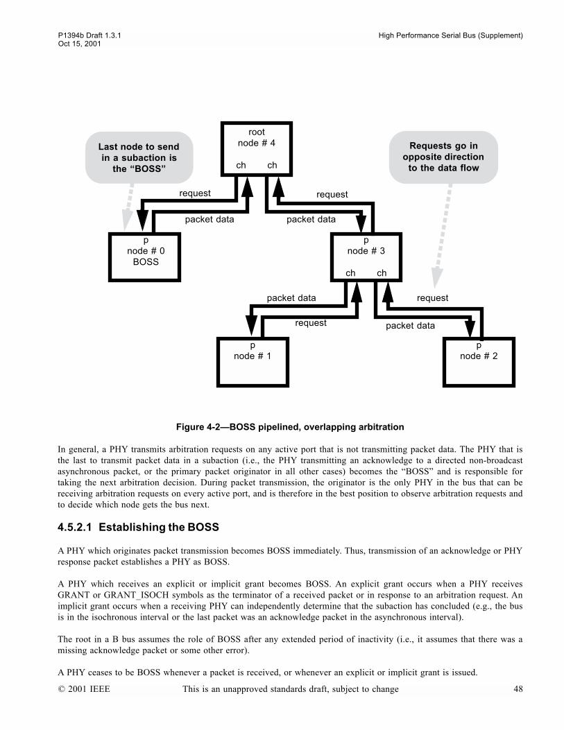
P1394b Draft 1.3.1 High Performance Serial Bus (Supplement)Oct 15, 2001
In general, a PHY transmits arbitration requests on any active port that is not transmitting packet data. The PHY that isthe last to transmit packet data in a subaction (i.e., the PHY transmitting an acknowledge to a directed non-broadcastasynchronous packet, or the primary packet originator in all other cases) becomes the BOSS and is responsible fortaking the next arbitration decision. During packet transmission, the originator is the only PHY in the bus that can bereceiving arbitration requests on every active port, and is therefore in the best position to observe arbitration requests andto decide which node gets the bus next.
4.5.2.1 Establishing the BOSS
A PHY which originates packet transmission becomes BOSS immediately. Thus, transmission of an acknowledge or PHYresponse packet establishes a PHY as BOSS.
A PHY which receives an explicit or implicit grant becomes BOSS. An explicit grant occurs when a PHY receivesGRANT or GRANT_ISOCH symbols as the terminator of a received packet or in response to an arbitration request. Animplicit grant occurs when a receiving PHY can independently determine that the subaction has concluded (e.g., the busis in the isochronous interval or the last packet was an acknowledge packet in the asynchronous interval).
The root in a B bus assumes the role of BOSS after any extended period of inactivity (i.e., it assumes that there was amissing acknowledge packet or some other error).
A PHY ceases to be BOSS whenever a packet is received, or whenever an explicit or implicit grant is issued.
Figure 4-2BOSS pipelined, overlapping arbitration
Requests go in opposite direction
to the data flow
Last node to send in a subaction is
the BOSS
rootnode # 4
ch ch
pnode # 0
BOSS
pnode # 3
ch ch
pnode # 1
pnode # 2
request
packet datapacket data
packet data
packet data
request
request
request
© 2001 IEEE This is an unapproved standards draft, subject to change 48
P1394b Draft 1.3.1 High Performance Serial Bus (Supplement)Oct 15, 2001
4.5.2.2 Tokens and bus intervals
In contrast to Legacy arbitration, where idle gaps are used to mark the end of the self-ID phase of bus-initialization, toterminate the isochronous interval, to indicate the end of a subaction in the asynchronous interval, and to indicate a fair-ness interval boundary, tokens are used in BOSS operation for these purposes. A token is a specially designated Beta con-trol symbol which is transmitted by the current BOSS for a specified minimum time to ensure reception throughout thebus. Tokens can be transmitted by the BOSS when the bus is otherwise idle or being held by transmission ofDATA_NULL symbols (i.e., the token is embedded within the DATA_NULL symbol stream).
As in Legacy operation, packet transmission in BOSS operation is divided into isochronous and asynchronous intervals.In a B bus, the isochronous interval begins when a CYCLE_START_EVEN/ODD token and cycle-start packet are trans-mitted by the cycle-master. The isochronous interval ends when the current BOSS has no in-phase isochronous requestspending either from its link or at any active Beta port, whereupon it transmits an ASYNC_EVEN/ODD token to begin theasynchronous interval. Additionally, an ASYNC_EVEN token is transmitted by the root in a B bus to indicate the end ofthe self-ID phase (the last phase of bus-initialization) and the start of normal arbitration.
The asynchronous interval is active whenever the bus is not in the isochronous interval. As in Legacy operation, the asyn-chronous interval is further divided into fairness intervals. In a B bus, the fairness interval boundary is marked by the cur-rent BOSS transmitting an ASYNC_EVEN/ODD token as appropriate for the new phase when it has no in-phaseasynchronous requests pending either from its attached link or at any active Beta port. It is possible for the boss to termi-nate both an isochronous interval and a fairness interval using a single transmission of an ASYNC_EVEN/ODD token.
To increase robustness against dropped tokens, the root in a B bus transmits ASYNC_EVEN/ODD tokens continuouslywhen the bus is idle.
4.5.2.3 Arbitration requests, pipelining, and phasing
In BOSS mode, arbitration is performed with 8B/10B Beta symbols. Unlike Legacy arbitration, which has only one linestate to signal an arbitration request, these arbitration request symbols incorporate both an asynchronous and isochronousrequest code, and allow multiple request types and priorities to be implemented.
The availability of multiple request types and priorities, in turn, facilitates arbitration pipelining, which is a mechanismwhereby requests meant to be serviced in the next isochronous interval or asynchronous fairness interval are transmittedand available to the BOSS far in advance of the BOSS having to take an arbitration decision on them. In order to fullyfacilitate pipelining, the concept of arbitration phase is introduced, where the arbitration phase alternates between evenand odd. Both the isochronous and asynchronous intervals have phase, which are independent of one another. The isoch-ronous phase advances at the end of the isochronous period (as indicated by the transmission of an ASYNC_EVEN/ODDtoken), and the asynchronous phase advances at each fairness interval boundary (as indicated by the transmission of anASYNC_EVEN/ODD token corresponding to the new phase). Following bus-reset, both the isochronous and asynchro-nous phases are defined to be even.
An arbitration request may be designated for the current phase (either even or odd) or the next/opposite phase (i.e., pipe-lined). Beta PHYs constantly forward the highest priority asynchronous and isochronous requests (combined into a singlerequest symbol) received from either its attached link or any active Beta ports towards the current BOSS. The priority ofarbitration requests is dependent upon the current bus interval and phase.
Following the transmission of a packet at the end of a subaction, the current BOSS will immediately grant the highest pri-ority pending request for the current interval and phase, if any. However, if at this time the BOSS is receiving no valid in-phase requests, it will transmit one or more tokens to advance the bus interval and/or phase:
a) If the bus is in the isochronous interval at the end of packet transmission and no in-phase isochronous requests arebeing received, the BOSS will transmit an ASYNC_EVEN/ODD token to terminate the isochronous interval andadvance to the asynchronous interval (but without changing the current asynchronous phase).
© 2001 IEEE This is an unapproved standards draft, subject to change 49
P1394b Draft 1.3.1 High Performance Serial Bus (Supplement)Oct 15, 2001
b) If the bus is in the asynchronous interval at the end of packet transmission at the end of a subaction, or hasentered the asynchronous interval by a) above, and no in-phase asynchronous requests are being received, theBOSS will transmit an ASYNC_EVEN/ODD token to advance the asynchronous phase and begin a new fairnessinterval.
c) If no in-phase requests are pending for the new asynchronous phase, the BOSS will grant control of the bus to itssenior (the peer PHY closest to the root), so that the root eventually assumes control in an idle B bus. Once anASYNC_EVEN/ODD token has been issued to change the phase, another token to change the phase again will notbe issued until after some asynchronous packet transmission has occurred in that phase.
In the asynchronous interval, a node can make a request for the current phase only if it has any priority budget remainingfor the current fairness interval, and nodes can make requests for the next asynchronous phase when they have no budgetremaining. Thus, this mechanism allows fairness to be implemented in a B bus without the use of idle gaps; the bus phaseis advanced only when all nodes that have data to transmit in the current fairness interval have done so.
4.5.2.4 Hybrid bus operation
The preceding discussion of BOSS arbitration is specifically concerned with operation in a B bus (consisting entirely ofB nodes). In a hybrid bus, this operation is modified so as to maintain interoperability and compatibility with Legacydevices. In particular, idle gaps must be maintained as required for the Legacy arbitration mechanisms.
Each B cloud in a hybrid bus contains only one senior border PHY, which is the border PHY with the highest physical-IDof all border PHYs in the cloud. The senior border PHY in the B cloud that contains the root is referred to as theproxy_root, and acts as the default arbiter when no other PHY is acting as BOSS. (It is possible that there is noproxy_root, as the root may be a Legacy PHY and therefore not part of any B cloud.) The parent port of a senior border(other than the proxy_root) is necessarily a DS mode port.
The senior border in each B cloud is responsible for ensuring that the Legacy gap timings are observed, and is the onlyPHY within the cloud allowed to issue ASYNC_EVEN/ODD tokens. In order to synchronize Legacy gap indications withBOSS token indications, the senior border will issue an ASYNC_EVEN/ODD token of the current phase whenever ittimes a subaction idle gap and will issue an ASYNC_EVEN/ODD token of the new phase whenever it times an arb-resetidle gap. It continues to issue the tokens for the current phase so long as the bus is idle.
In response to Beta arbitration requests, the senior border will begin arbitration for the bus, but will do so in accordancewith the Legacy rules for initiating arbitration so as to ensure consistent bus-wide detection of gaps. A grant can be issued(if proxy_root) or arbitration on the DS mode parent port can begin:
a) up to arb_delay following the issuance of an ASYNC_EVEN/ODD token indicating a subaction gap providedthe previous packet represented the end of a subaction (ACK-accelerated arbitration),
b) at arb_delay following the issuance of an ASYNC_EVEN/ODD token indicating a subaction gap,c) anytime after the arb_delay following the issuance of an ASYNC_EVEN/ODD token indicating a new fairness
interval, or d) within ARB_RESPONSE_DELAY after receiving a LEGACY_REQUEST or ISOCH_CURRENT request.
When the senior border wins arbitration, it will begin BOSS mode arbitration and Beta traffic can begin. Once Beta trafficbegins in a B cloud, BOSS arbitration will persist until the end of a subaction has been reached and there are no more in-phase requests pending from any of the nodes in the cloud.
During this period of Beta traffic, Legacy devices shall be prevented from detecting any idle gaps. Legacy formattedpackets are repeated by a border PHY directly to any DS ports as normal (with DATA_PREFIX replacing the payload ifthe packet speed is greater than the peers capability). For Beta formatted packets, a border will begin generatingDATA_PREFIX on its DS ports. Because the border node meets minimum DATA_PREFIX/DATA_END timings andcannot predict when the next Legacy formatted packet will arrive, it cannot safely release DATA_PREFIX until such apacket arrives. Instead, it must hold DATA_PREFIX on the DS ports until a Legacy formatted packet arrives. The Legacypacket is concatenated onto the DATA_PREFIX and is received normally by Legacy devices. To ensure that border PHYs
© 2001 IEEE This is an unapproved standards draft, subject to change 50
P1394b Draft 1.3.1 High Performance Serial Bus (Supplement)Oct 15, 2001
do not get stuck sending DATA_PREFIX indefinitely on their DS ports, the BOSS in a B cloud is required to issue aLegacy null-packet whenever the end of a subaction has been reached, there are no more in-phase requests pending, andthe last packet sent was not a Legacy formatted packet.
At the end of Beta traffic, the current BOSS does not transmit any tokens, but instead simply grants control of the bus toits senior. Control is eventually transferred to the senior border, which begins timing the idle gap.
In a hybrid bus, CYCLE_START tokens can exist only in the B cloud which contains a cycle-master operating in B mode.This B cloud, if there is one, is referred to as the senior B cloud. (It is possible that there is no senior B cloud, as thecycle-master may not be in a B cloud.) Any B cloud which is not the senior B cloud is referred to as a junior B cloud.Tokens cannot be transmitted across the DS connections between B clouds, and reproducing the CYCLE_START tokensin the junior B clouds is problematic.
Therefore, a PHY in a junior B cloud becomes aware of the start of the isochronous interval when it receives aPH_ISOCH_PHASE_EVEN/ODD notification from an attached isochronous-capable link, which notification alsoinforms the PHY of the isochronous phase. Upon receiving this notification, the PHY will begin sendingISOCH_CURRENT arbitration requests if it has an in-phase isochronous request pending from its link. TheISOCH_CURRENT request is the highest priority isochronous request and is eventually received by the senior border;ISOCH_EVEN/ODD requests are never generated within a junior B cloud. The senior border responds to anISOCH_CURRENT request by immediately arbitrating for the bus.
4.5.2.4.1 Legacy request phasing
In Legacy IEEE 1394, a node arbitrates for control of the bus by sending a TX_REQUEST signal on its parent port andsending TX_DATA_PREFIX on its child ports to deny them access to the bus. In response to this arbitration request, itwill receive either a RX_GRANT or RX_DATA_PREFIX signal on its parent port. If RX_GRANT is received, control ofthe bus has been won and the node can begin packet transmission. If RX_DATA_PREFIX is received, arbitration has beenlost and another node has been granted control of the bus to transmit a packet; the node must withdraw theTX_REQUEST on its parent port and prepare to receive the impending packet. This signaling handshake must occurbefore the start of clocked packet data so as to avoid signal contention and interference with the packet data on thetwisted pair. In Legacy IEEE 1394, the various packet timing constants (MIN_DATA_PREFIX,ARB_RESPONSE_DELAY, etc.) were defined such that this signaling handshake would complete in time, but assumed amaximum round trip delay of about 45 ns on the cable connection (corresponding to 4.5 meters of copper twisted pair).
A border node will convert a received RX_REQUEST signal on a DS mode port to Beta LEGACY_REQUEST symbols,and arbitration proceeds in a similar fashion as for Legacy IEEE 1394; junior ports are denied by sending DATA_PREFIXon them and LEGACY_REQUEST is sent on the senior port. If arbitration is won a GRANT or GRANT_ISOCH isreturned, and if arbitration is lost a DATA_PREFIX or DATA_NULL is returned.
This standard allows Beta mode connections of up to 100 meters on UTP5, HPCF, or MMF media, with correspondinground trip cable delays of well over 1 µs. Such long cable delays present a problem for Legacy style arbitration in that thesignaling handshake described above may not complete in time; if a node is sending a LEGACY_REQUEST on its seniorport and arbitration is lost, the LEGACY_REQUEST at the senior node wont be withdrawn before packet transmissionbegins. Because of the full-duplex nature of a Beta mode connection, theres no danger of signal contention as there is ona DS mode connection, but there is the possibility of stale requests.
A stale request can occur when a junior node begins sending LEGACY_REQUEST at about the same time that its seniornode begins transmission of a packet. If the packet is short and the cable long, the senior can complete transmission of theentire packet before receiving the first indication of LEGACY_REQUEST from the junior, which will be withdrawn assoon as the junior receives the packet. Without some mechanism for recognizing this as a stale request, the senior wouldotherwise act on the LEGACY_REQUEST, perhaps interfering with an impending ACK.
To resolve the problem of stale LEGACY_REQUESTs, the concept of Legacy request phase is introduced. EachLEGACY_REQUEST symbol incorporates a 2-bit field containing a Legacy request phase number, which ranges from 0to 3. A received LEGACY_REQUEST is considered valid only if its Legacy request phase number is equal to the nodes
© 2001 IEEE This is an unapproved standards draft, subject to change 51

P1394b Draft 1.3.1 High Performance Serial Bus (Supplement)Oct 15, 2001
own stored value for Legacy request phase, and is otherwise considered a stale request. (The Legacy request phase doesnot affect requests received at a DS mode port; a RX_REQUEST signal received on a DS mode port is always consideredvalid and is immediately acted upon.)
Whenever a node originates a Legacy format packet into a Beta cloud (either as original transmitter of the packet, orwhen repeating a packet into a Beta cloud from a DS mode port), and which packet is terminated with DATA_END, orwith GRANT/GRANT_ISOCH on the senior port, it increments its Legacy request phase number. The new Legacyrequest phase number is then communicated to all other nodes in the local Beta cloud via a LEGACY_PHASE token thatcompletes the Legacy format packet ending symbol sequence. Receiving nodes update their own Legacy request phasenumber with the new value contained in the LEGACY_PHASE token. If the LEGACY_PHASE token is corrupted or oth-erwise not received when it is expected, a receiving node will increment its own Legacy request phase number and usethis value when repeating the packet. Upon bus-reset, the Legacy request phase is set to 0.
4.6 PHY-Link interface, general interface characteristics
This specification contains two new definitions for the PHY-Link interface. The first of these represents an evolutionarychange from the Legacy PHY/link interface specification. The second interface is an adaptation of the high-speed, Beta-mode serial interface that offers greater flexibility in system implementation, allows higher speeds and longer distancesbetween the PHY and the Link.
4.6.1 Evolutionary PHY-Link Interface
The evolutionary interface is an 8-bit, parallel data interface that has been enhanced to allow data transfers at speeds ofup to S800 and to support the additional request types required by this standard.
The evolutionary interface is specified as being more symmetrical, in order to avoid any deadlock or long latency situa-tions where the Link or PHY device is prevented from communicating with the other while a lengthy operation is takingplace. This enhancement was made possible by inclusion of a unidirectional signaling line from the PHY to the Link overwhich status information can be sent while the data bus is busy with packet data. Additionally, a clock is added at theLink which is used when the data lines are carrying data from the Link to the PHY. This allows source synchronous trans-fers in both directions which greatly simplifies the problems associate with moving data at high speeds.
In general, the PHY device is the owner of the PHY-Link interface. All Serial Bus packets are transferred to the Linkdevice as they are received. The Link requests the use of the Serial bus via the PHY device. The PHY interprets andqueues the Link transmit requests as appropriate. When the PHY is granted access to the bus, the PHY passes that grantto the Link which then transmits data as required.
From a functional point of view, the PHY-Link interface can be viewed as a master- slave interface. At any point in time,either the PHY or the Link is the current owner of the interface, and a handoff mechanism to pass ownership from one tothe other is defined.
4.6.2 Serial PHY-Link Interface
During the development of this specification, a great deal of effort was spent on trying to extend the capabilities of theLegacy style PHY-Link interface. It became evident that it would be difficult to continue to increase the transfer speedswithout making the interface wider. This, it was felt, would compromise the system design not only because of theincreased pin counts on the PHY and the Link devices but also because of the implications to circuit board designs, espe-cially those that incorporated galvanic isolation between the PHY and the Link. Additional problems were encountered intrying to accommodate future voltage scaling that might result in the PHY and the Link running on different supply volt-ages with different signal swings.
© 2001 IEEE This is an unapproved standards draft, subject to change 52

P1394b Draft 1.3.1 High Performance Serial Bus (Supplement)Oct 15, 2001
Because of the problems mentioned above, a second PHY-Link interface has been defined in this specification. This inter-face uses the standard Beta mode signaling between the Link and a fanout PHY. The Link, therefore, contains what isnearly the functional equivalent of a Beta-mode PHY. The PHY integrated into the Link arbitrates directly for the serialbus by using standard BOSS mode arbitration which eliminates the need for LREQ.
The PHY that is integrated into the Link can be a simplified version of a standard Beta-mode only PHY since this PHYdoes not participate in tree-ID or self-ID. Additionally, since this PHY is always a leaf node, this PHY does not need toparticipate in the loop-free-build process.
In order to preserve software compatibility with the Legacy model of the PHY-Link interface, the PHY in the Link sharesthe node ID of the fanout PHY. Additionally, a special packet format allows the Link to transmit and receive PHY registerdata to/from the fanout PHY over the two signaling pairs. This allows software to access the fanout PHY as if it wereattached through the Legacy PHY-Link interface.
The new interface continues to have a Link_On signal.
4.7 Miscellaneous features
This standard has greatly enhanced the PHY state machines to use autonegotiation to determine the speed and mode ofsignaling to be used between nodes. Since nodes may be connected through optical media there can be no assurance ofseeing DC bias changes to indicate connection changes. This standard solves the connection change problem by the useof tones which are detected and acted upon in an handshake manner. Autonegotiation supports DC copper connections,AC coupled copper and purely optical connections. Beta mode is used if at all possible. DS mode is used for bilingualports when a DS only node is detected on the other side of the connection. Autonegotiation takes place before Bus Reset,Tree ID, etc., occur.
A new feature is loop breaking. Loops are automatically removed during initialization.
4.7.1 Power Conservation Improvements
This standard adds Standby and Restore features for power conservation beyond the suspend/resume features of IEEE Std1394a-2000. Standby is restricted to leaf nodes and bus resets do not occur when a port enters and comes out of Standby.When the PHYs port is in the Standby state, it may enter a low-power mode with power consumption similar to thatattained when in the Suspended state.
4.7.2 Standby
Standby is a feature only of Beta-mode operation.
Nephew is used to label a leaf node that has a port in the Standby state.
The active node connected to a nephew node is an uncle.
Though a nephew does not participate in normal bus activity, the active bus, of which the nephew is a member, is notaware of a change in status of a node as it becomes a nephew, i.e. a bus reset does not occur.
If a bus reset occurs while a nephew has a port in Standby, then the uncle proxies self-ID packet(s) on behalf of anephew.
A node becomes nephew when it detects a Standby command packet containing its Node-ID and port address.
A root node, a node with more than one active port, or a node that has another port already in Standby cannot become anephew.
© 2001 IEEE This is an unapproved standards draft, subject to change 53

High Performance Serial Bus (Supplement) P1394b Draft 1.3.1Oct 15, 2001
4.7.3 Restore
The port in Standby on the nephew restores from Standby upon detecting a restore tone from its uncle.
A nephew restores its port from Standby when it receives any arbitration request from its link, i.e. the nephews portasserts a restore tone to its uncle.
Upon detecting or generating a restore tone a nephew begins monitoring for a PHY packet. The PHY packet containsinformation used by the nephew to restore context, i.e. bus phase, node-ID, gap count, and gap count sticky-bit status.
A multi-port node with one connected port in Standby restores that port followed by a bus reset if, on any of its otherports, it detects a resume or a new connection.
54 This is an unapproved standards draft, subject to change © 2001 IEEE

P1394b Draft 1.3.1 High Performance Serial Bus (Supplement)Oct 15, 2001
5. Copper physical medium dependent cable media attachment
This specification defines a new media and connector in order to support the higher data rates defined in this standard.This media and connector are known as the Beta interface. This interface is usable at speeds up to the maximum definedby this standard, S1600. To enable interoperability with Legacy devices, a keyed version of the Beta connector is defined.This connector allows bilingual ports to be attached to either Legacy (DS) ports or to Beta-only ports. The Beta connectoris used to prevent Legacy ports from being attached to Beta-only ports. An interconnect matrix is provided in subsequentsections of this clause.
The Beta interface has been designed to meet the small size requirements of consumer electronics devices while meetingthe higher speed and power distribution needs of computer and peripheral devices.
The 4 and 6 circuit receptacles defined in IEEE std 1394-1995 and IEEE std 1394a-2000 shall not be used on a port thatis capable of operating in Beta mode. Only the receptacles defined in this clause are allowed for use for short-haul(< 5M) copper connections on a Beta mode capable port.
5.1 Connectors
The connectors and cables defined in this section are used to interconnect B nodes at distances of up to 4.5 meters. Thisclause specifies the electrical and physical properties of the Beta and Bilingual cables and connectors. Some of the con-nector attributes that are not directly specified in this section are implied by the performance requirements in clause 5.3.
Informative data about the recommended planar mounting footprints of the sockets is found in figures 5-18 and 5-19.Compliance to these footprints is optional but performance of alternative footprints should be comparable to those shownin this specification.
In typical applications computer, consumer electronic or peripheral equipment boxes may shall present one or more sock-ets, for attachment to other boxes via cables. The detachable ends of the cable shall be terminated with plugs. This stan-dard defines the copper Beta and Bilingual cables and their mating PCB socket interfaces.
All dimensions, tolerances and descriptions of features which affect the intermateability of the Beta, Bilingual plugs andsockets are specified within this clause. Connector features which are not directly controlled within this clause will beindirectly controlled by performance requirements in clause 5.3.
© 2001 IEEE This is an unapproved standards draft, subject to change 55
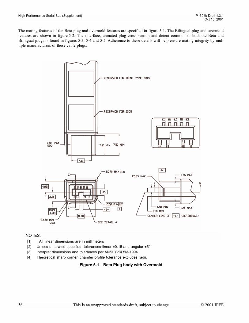
High Performance Serial Bus (Supplement) P1394b Draft 1.3.1Oct 15, 2001
The mating features of the Beta plug and overmold features are specified in figure 5-1. The Bilingual plug and overmoldfeatures are shown in figure 5-2. The interface, unmated plug cross-section and detent common to both the Beta andBilingual plugs is found in figures 5-3, 5-4 and 5-5. Adherence to these details will help ensure mating integrity by mul-tiple manufacturers of these cable plugs.
NOTES:
[1] All linear dimensions are in millimeters
[2] Unless otherwise specified, tolerances linear ±0.15 and angular ±5°
[3] Interpret dimensions and tolerances per ANSI Y-14.5M-1994
[4] Theoretical sharp corner, chamfer profile tolerance excludes radii.
Figure 5-1Beta Plug body with Overmold
56 This is an unapproved standards draft, subject to change © 2001 IEEE

P1394b Draft 1.3.1 High Performance Serial Bus (Supplement)Oct 15, 2001
NOTES:
[1] All linear dimensions are in millimeters
[2] Unless otherwise specified, tolerances linear ±0.15 and angular ±5°
[3] Interpret dimensions and tolerances per ANSI Y-14.5M-1994
[4] Theoretical sharp corner, chamfer profile tolerance excludes radii.
Figure 5-2Bilingual Plug Body with Overmold
© 2001 IEEE This is an unapproved standards draft, subject to change 57

High Performance Serial Bus (Supplement) P1394b Draft 1.3.1Oct 15, 2001
NOTES:
[1] All linear dimensions are in millimeters
[2] Unless otherwise specified, tolerances linear ±0.15 and angular ±5°
[3] Interpret dimensions and tolerances per ANSI Y-14.5M-1994
Figure 5-3Beta/Bilingual Plug Interface Detail A.
RADIUS PERMITTED
58 This is an unapproved standards draft, subject to change © 2001 IEEE
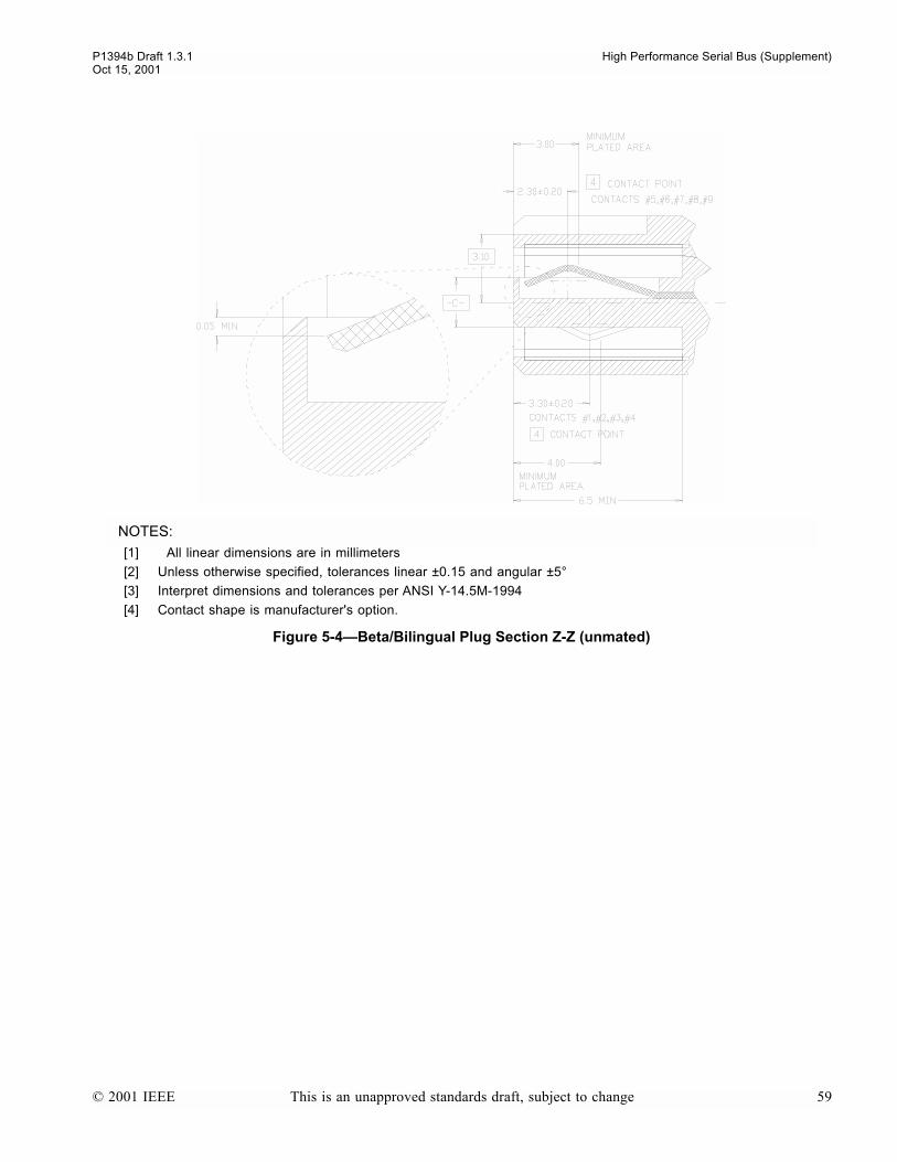
P1394b Draft 1.3.1 High Performance Serial Bus (Supplement)Oct 15, 2001
NOTES:
[1] All linear dimensions are in millimeters
[2] Unless otherwise specified, tolerances linear ±0.15 and angular ±5°
[3] Interpret dimensions and tolerances per ANSI Y-14.5M-1994
[4] Contact shape is manufacturer's option.
Figure 5-4Beta/Bilingual Plug Section Z-Z (unmated)
© 2001 IEEE This is an unapproved standards draft, subject to change 59

High Performance Serial Bus (Supplement) P1394b Draft 1.3.1Oct 15, 2001
5.1.1 Plug cable termination method
The termination of the Beta and Bilingual cable medias conductor wires to the plug contacts shall be either solder orwelded.
5.1.2 Socket
The mating features of the Beta socket are described in figures 5-6 and 5-7. The detail will assure the intermateability ofthe socket with the plugs specified by this supplement. The mating features of the Bilingual socket are described in fig-ures 5-8 and 5-9. In figures 5-10 through 5-15 you will find interface details that are common to both Beta and Bilingualsockets. Figure 5-16 shows mated detent cross sections common to both Beta and Bilingual plugs and sockets. The detentfeature details will assure the intermateability of the socket with the plugs specified by this supplement. Materials utilizedin the fabrication of the Beta/Bilingual sockets shall be capable of withstanding IR reflow temperatures.
Contact assignment for either PCB socket is found in table 5-1.
Figure 5-5Beta/Bilingual Detent cross section S-S
Table 5-1Socket contact assignment (Sheet 1 of 2)
Contact number Signal name Comment
1 TPB* Twisted Pair B (Minus)
2 TPB Twisted Pair B (Plus)
3 TPA* Twisted Pair A (Minus)
4 TPA Twisted Pair A (Plus)
5 TPA (R) Twisted Pair A (Reference Ground)
6 VG Power (Ground)
60 This is an unapproved standards draft, subject to change © 2001 IEEE
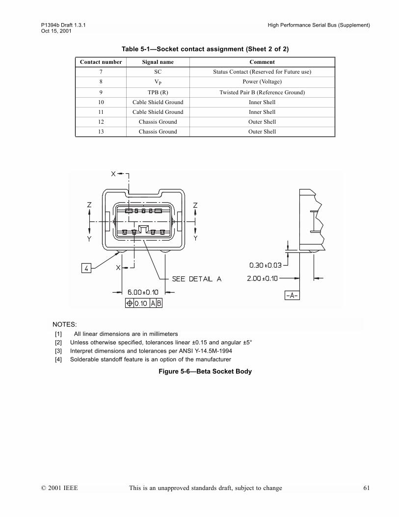
P1394b Draft 1.3.1 High Performance Serial Bus (Supplement)Oct 15, 2001
7 SC Status Contact (Reserved for Future use)
8 VP Power (Voltage)
9 TPB (R) Twisted Pair B (Reference Ground)
10 Cable Shield Ground Inner Shell
11 Cable Shield Ground Inner Shell
12 Chassis Ground Outer Shell
13 Chassis Ground Outer Shell
NOTES:
[1] All linear dimensions are in millimeters
[2] Unless otherwise specified, tolerances linear ±0.15 and angular ±5°
[3] Interpret dimensions and tolerances per ANSI Y-14.5M-1994
[4] Solderable standoff feature is an option of the manufacturer
Figure 5-6Beta Socket Body
Table 5-1Socket contact assignment (Sheet 2 of 2)
Contact number Signal name Comment
© 2001 IEEE This is an unapproved standards draft, subject to change 61

High Performance Serial Bus (Supplement) P1394b Draft 1.3.1Oct 15, 2001
NOTES:
[1] All linear dimensions are in millimeters
[2] Unless otherwise specified, tolerances linear ±0.15 and angular ±5°
[3] Interpret dimensions and tolerances per ANSI Y-14.5M-1994
[4] Theoretical sharp corner, chamfer profile tolerance excludes radii.
[5] Socket detent feature shall retain standard plug shape and contacts in reliable contact position under cable tension up to the minimum retention force.
Figure 5-7Beta socket outer shell profile
62 This is an unapproved standards draft, subject to change © 2001 IEEE

P1394b Draft 1.3.1 High Performance Serial Bus (Supplement)Oct 15, 2001
NOTES:
[1] All linear dimensions are in millimeters
[2] Unless otherwise specified, tolerances linear ±0.15 and angular ±5°
[3] Interpret dimensions and tolerances per ANSI Y-14.5M-1994
[4] Solderable standoff feature is an option of the manufacturer
Figure 5-8Bilingual socket body
© 2001 IEEE This is an unapproved standards draft, subject to change 63

High Performance Serial Bus (Supplement) P1394b Draft 1.3.1Oct 15, 2001
NOTES:
[1] All linear dimensions are in millimeters
[2] Unless otherwise specified, tolerances linear ±0.15 and angular ±5°
[3] Interpret dimensions and tolerances per ANSI Y-14.5M-1994
[4] Theoretical sharp corner, chamfer profile tolerance excludes radii.
[5] Socket detent feature shall retain standard plug shape and contacts in reliable contact position under cable tension up to the minimum retention force.
Figure 5-9Bilingual socket outer shell profile
64 This is an unapproved standards draft, subject to change © 2001 IEEE
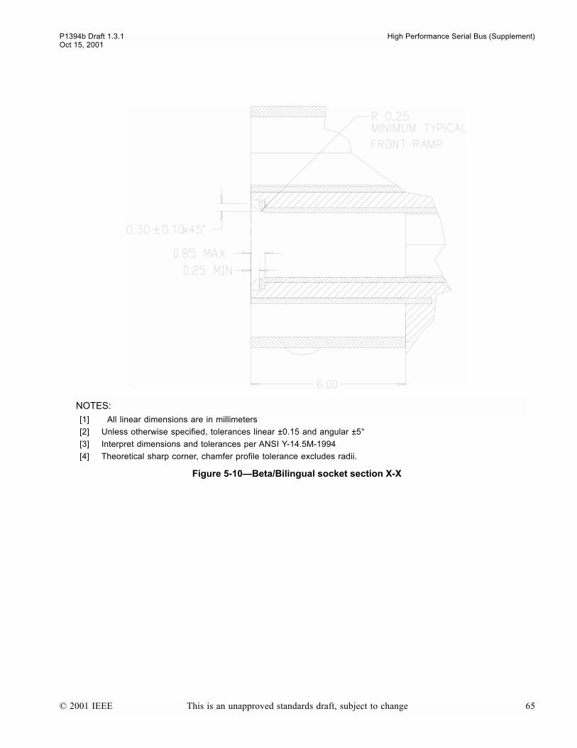
P1394b Draft 1.3.1 High Performance Serial Bus (Supplement)Oct 15, 2001
NOTES:
[1] All linear dimensions are in millimeters
[2] Unless otherwise specified, tolerances linear ±0.15 and angular ±5°
[3] Interpret dimensions and tolerances per ANSI Y-14.5M-1994
[4] Theoretical sharp corner, chamfer profile tolerance excludes radii.
Figure 5-10Beta/Bilingual socket section X-X
© 2001 IEEE This is an unapproved standards draft, subject to change 65

High Performance Serial Bus (Supplement) P1394b Draft 1.3.1Oct 15, 2001
NOTES:
[1] All linear dimensions are in millimeters
[2] Unless otherwise specified, tolerances linear ±0.15 and angular ±5°
[3] Interpret dimensions and tolerances per ANSI Y-14.5M-1994
[4] Contact shape is the manufacturers option, but should be a spring member
Figure 5-11Beta/Bilingual socket section Y-Y
66 This is an unapproved standards draft, subject to change © 2001 IEEE
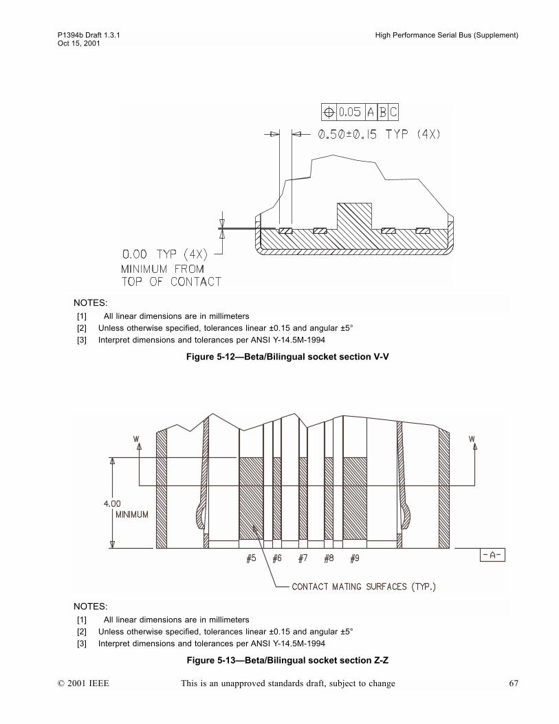
P1394b Draft 1.3.1 High Performance Serial Bus (Supplement)Oct 15, 2001
NOTES:
[1] All linear dimensions are in millimeters
[2] Unless otherwise specified, tolerances linear ±0.15 and angular ±5°
[3] Interpret dimensions and tolerances per ANSI Y-14.5M-1994
Figure 5-12Beta/Bilingual socket section V-V
NOTES:
[1] All linear dimensions are in millimeters
[2] Unless otherwise specified, tolerances linear ±0.15 and angular ±5°
[3] Interpret dimensions and tolerances per ANSI Y-14.5M-1994
Figure 5-13Beta/Bilingual socket section Z-Z
© 2001 IEEE This is an unapproved standards draft, subject to change 67

High Performance Serial Bus (Supplement) P1394b Draft 1.3.1Oct 15, 2001
NOTES:
[1] All linear dimensions are in millimeters
[2] Unless otherwise specified, tolerances linear ±0.15 and angular ±5°
[3] Interpret dimensions and tolerances per ANSI Y-14.5M-1994
Figure 5-14Beta/Bilingual socket section W-W
68 This is an unapproved standards draft, subject to change © 2001 IEEE
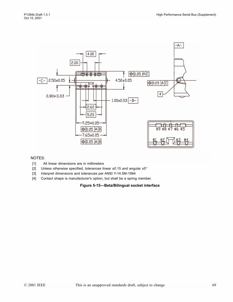
P1394b Draft 1.3.1 High Performance Serial Bus (Supplement)Oct 15, 2001
NOTES:
[1] All linear dimensions are in millimeters
[2] Unless otherwise specified, tolerances linear ±0.15 and angular ±5°
[3] Interpret dimensions and tolerances per ANSI Y-14.5M-1994
[4] Contact shape is manufacturer's option, but shall be a spring member.
Figure 5-15Beta/Bilingual socket interface
© 2001 IEEE This is an unapproved standards draft, subject to change 69
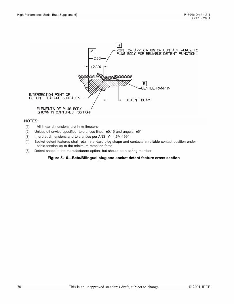
High Performance Serial Bus (Supplement) P1394b Draft 1.3.1Oct 15, 2001
NOTES:
[1] All linear dimensions are in millimeters
[2] Unless otherwise specified, tolerances linear ±0.15 and angular ±5°
[3] Interpret dimensions and tolerances per ANSI Y-14.5M-1994
[4] Socket detent features shall retain standard plug shape and contacts in reliable contact position under cable tension up to the minimum retention force
[5] Detent shape is the manufacturers option, but should be a spring member
Figure 5-16Beta/Bilingual plug and socket detent feature cross section
70 This is an unapproved standards draft, subject to change © 2001 IEEE

P1394b Draft 1.3.1 High Performance Serial Bus (Supplement)Oct 15, 2001
When mounted on a PCB, the socket shall be at a fixed height and minimum side to side spacing as illustrated byfigure 5-17.
5.1.3 Mating Area finish on plug and socket contacts
It is necessary to standardize the electroplated finish on the contacts to assure the compatibility of plugs and sockets fromdifferent sources. The following standardized electroplatings are compatible and one shall be used on mating contact sur-faces.
a) 0.76 µm (30µin), minimum, gold, over 1.27 µm (50 µin), minimum, nickel, orb) 0.05 µm (2 µin), minimum, gold, over 0.76 µm (30 µin), minimum, palladium-nickel alloy (80% Pd20% Ni),
over 1.27 µm (50 µin), minimum, nickel.
NOTES
1Selective plating on the mating contact surfaces is acceptable. In that case, the above electroplating shall cover the complete area ofcontact, including the contact wipe area.
2A copper strike is acceptable, under the nickel electroplate.
5.1.4 Termination Area finish on plug and socket contacts
It is acceptable to use an electroplate of tin or tin alloy for the PCB and cable conductor termination with a minimumthickness of 3.04 µm (120 µin) over 1.27 µm (50 µin), minimum, nickel. A copper strike is acceptable under the nickel.
NOTES:
[1] All linear dimensions are in millimeters
[2] Unless otherwise specified, tolerances linear ±0.15 and angular ±5°
[3] Interpret dimensions and tolerances per ANSI Y-14.5M-1994
[4] Minimum mounting interval
[5] Datum -C- of PCB sockets
Figure 5-17Socket(s) position when mounted on a PCB
© 2001 IEEE This is an unapproved standards draft, subject to change 71
High Performance Serial Bus (Supplement) P1394b Draft 1.3.1Oct 15, 2001
5.1.5 Shell finish on plugs and sockets
All shells shall be electroplated with a minimum of 3.03 µm (120 µin) of tin or tin alloy over a suitable barrier underplate,such as copper or nickel.
5.1.6 Durability
The requirements of different end-use applications call for connectors which can be mated and unmated a number oftimes, without degrading performance beyond acceptable limits. Accordingly, this supplement specifies minimum perfor-mance criteria of 1000 mating cycles.
72 This is an unapproved standards draft, subject to change © 2001 IEEE
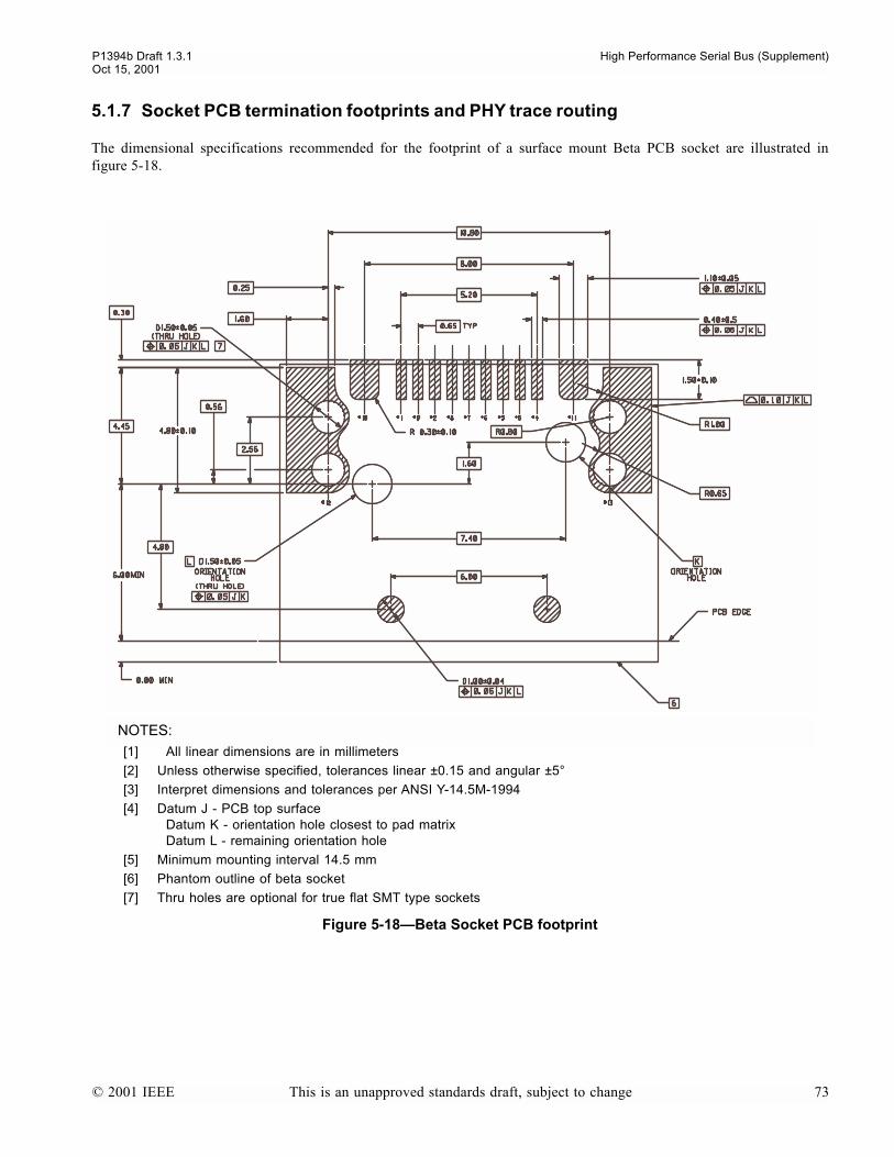
P1394b Draft 1.3.1 High Performance Serial Bus (Supplement)Oct 15, 2001
5.1.7 Socket PCB termination footprints and PHY trace routing
The dimensional specifications recommended for the footprint of a surface mount Beta PCB socket are illustrated infigure 5-18.
NOTES:
[1] All linear dimensions are in millimeters
[2] Unless otherwise specified, tolerances linear ±0.15 and angular ±5°
[3] Interpret dimensions and tolerances per ANSI Y-14.5M-1994
[4] Datum J - PCB top surfaceDatum K - orientation hole closest to pad matrixDatum L - remaining orientation hole
[5] Minimum mounting interval 14.5 mm
[6] Phantom outline of beta socket
[7] Thru holes are optional for true flat SMT type sockets
Figure 5-18Beta Socket PCB footprint
© 2001 IEEE This is an unapproved standards draft, subject to change 73
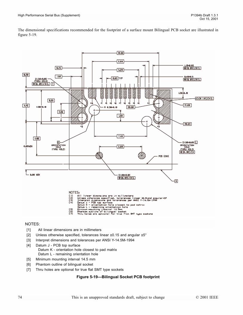
High Performance Serial Bus (Supplement) P1394b Draft 1.3.1Oct 15, 2001
The dimensional specifications recommended for the footprint of a surface mount Bilingual PCB socket are illustrated infigure 5-19.
NOTES:
[1] All linear dimensions are in millimeters
[2] Unless otherwise specified, tolerances linear ±0.15 and angular ±5°
[3] Interpret dimensions and tolerances per ANSI Y-14.5M-1994
[4] Datum J - PCB top surfaceDatum K - orientation hole closest to pad matrixDatum L - remaining orientation hole
[5] Minimum mounting interval 14.5 mm
[6] Phantom outline of bilingual socket
[7] Thru holes are optional for true flat SMT type sockets
Figure 5-19Bilingual Socket PCB footprint
74 This is an unapproved standards draft, subject to change © 2001 IEEE
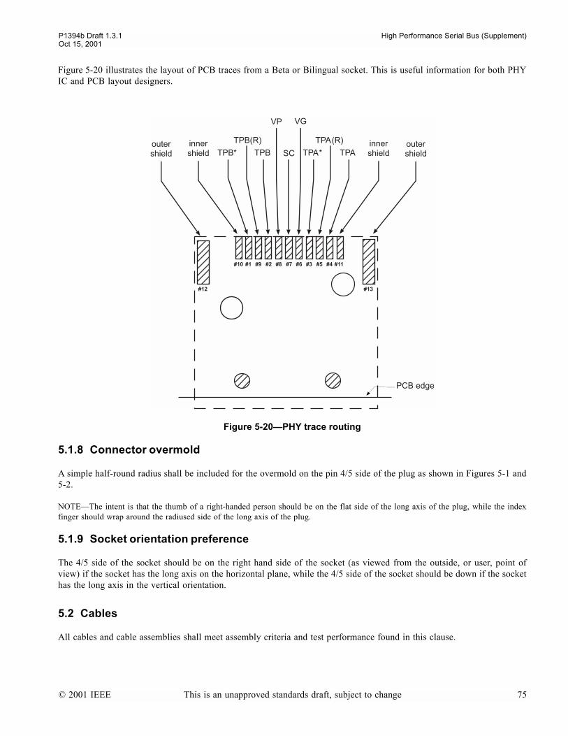
P1394b Draft 1.3.1 High Performance Serial Bus (Supplement)Oct 15, 2001
Figure 5-20 illustrates the layout of PCB traces from a Beta or Bilingual socket. This is useful information for both PHYIC and PCB layout designers.
5.1.8 Connector overmold
A simple half-round radius shall be included for the overmold on the pin 4/5 side of the plug as shown in Figures 5-1 and5-2.
NOTEThe intent is that the thumb of a right-handed person should be on the flat side of the long axis of the plug, while the indexfinger should wrap around the radiused side of the long axis of the plug.
5.1.9 Socket orientation preference
The 4/5 side of the socket should be on the right hand side of the socket (as viewed from the outside, or user, point ofview) if the socket has the long axis on the horizontal plane, while the 4/5 side of the socket should be down if the sockethas the long axis in the vertical orientation.
5.2 Cables
All cables and cable assemblies shall meet assembly criteria and test performance found in this clause.
Figure 5-20PHY trace routing
© 2001 IEEE This is an unapproved standards draft, subject to change 75
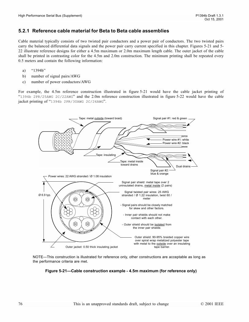
High Performance Serial Bus (Supplement) P1394b Draft 1.3.1Oct 15, 2001
5.2.1 Reference cable material for Beta to Beta cable assemblies
Cable material typically consists of two twisted pair conductors and a power pair of conductors. The two twisted pairscarry the balanced differential data signals and the power pair carry current specified in this chapter. Figures 5-21 and 5-22 illustrate reference designs for either a 4.5m maximum or 2.0m maximum length cable. The outer jacket of the cableshall be printed in contrasting color for the 4.5m and 2.0m construction. The minimum printing shall be repeated every0.5 meters and contain the following information:
a) 1394bb) number of signal pairs/AWGc) number of power conductors/AWG
For example, the 4.5m reference construction illustrated in figure 5-21 would have the cable jacket printing of1394b 2PR/25AWG 2C/22AWG and the 2.0m reference construction illustrated in figure 5-22 would have the cablejacket printing of 1394b 2PR/30AWG 2C/26AWG.
Figure 5-21Cable construction example - 4.5m maximum (for reference only)
Tape: metal outside (toward braid)
Tape: insulating
Tape: metal inside toward drains
Power wire #1: whitePower wire #2: black
Signal pair #2:blue & orange
Signal pair #1: red & green
Dual drains
Power wires: 22 AWG stranded / Ø 1.08 insulation
Ø 6.9 typ.
Signal pair shield: metal tape over 2 uninsulated drains, metal inside (2 pairs)
Signal twisted pair wires: 25 AWG stranded / Ø 1.22 insulation, twist 60 /
meter
- Signal pairs should be closely matched for skew and other factors.
- Inner pair shields should not make contact with each other.
- Outer shield should be isolated from the inner pair shields
Outer shield: 90-95% braided copper wire over spiral wrap metalized polyester tape
with metal to the outside over an insulating tape barrier.Outer jacket: 0.50 thick insulating jacket
NOTEThis construction is illustrated for reference only, other constructions are acceptable as long as the performance criteria are met.
76 This is an unapproved standards draft, subject to change © 2001 IEEE
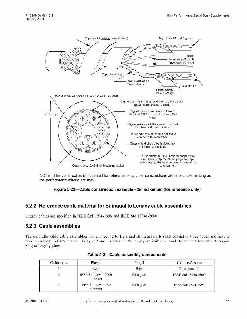
P1394b Draft 1.3.1 High Performance Serial Bus (Supplement)Oct 15, 2001
5.2.2 Reference cable material for Bilingual to Legacy cable assemblies
Legacy cables are specified in IEEE Std 1394-1995 and IEEE Std 1394a-2000.
5.2.3 Cable assemblies
The only allowable cable assemblies for connecting to Beta and Bilingual ports shall consist of three types and have amaximum length of 4.5 meters. The type 2 and 3 cables are the only permissible methods to connect from the Bilingualplug to Legacy plugs.
Figure 5-22Cable construction example - 2m maximum (for reference only)
Table 5-2Cable assembly components
Cable type Plug 1 Plug 2 Cable reference
1 Beta Beta This standard
2 IEEE Std 1394a-2000 4-circuit
Bilingual IEEE Std 1394a-2000
3 IEEE Std 1394-1995 6-circuit
Bilingual IEEE Std 1394-1995
Tape: metal outside (toward braid)
Tape: insulating
Tape: metal inside toward drains
Power wire #1: whitePower wire #2: black
Signal pair #2:blue & orange
Signal pair #1: red & green
Dual drains
Power wires: 26 AWG stranded / Ø 0.78 insulation
Ø 5.0 typ.
Signal pair shield: metal tape over 2 uninsulated drains, metal inside (2 pairs)
Signal twisted pair wires: 30 AWG stranded / Ø 0.8 insulation, twist 60 /
meter
- Signal pairs should be closely matched for skew and other factors.
- Inner pair shields should not make contact with each other.
- Outer shield should be isolated from the inner pair shields
Outer shield: 90-95% braided copper wire over spiral wrap metalized polyester tape
with metal to the outside over an insulating tape barrier.Outer jacket: 0.48 thick insulating jacket
NOTEThis construction is illustrated for reference only, other constructions are acceptable as long as the performance criteria are met.
© 2001 IEEE This is an unapproved standards draft, subject to change 77

High Performance Serial Bus (Supplement) P1394b Draft 1.3.1Oct 15, 2001
This new classification of cables specified in this clause will operate at a range of speeds based on the performance crite-ria set by the connectors and cables. Table 5-3 shows the various interfaces.
Figure 5-23Interface Mating Chart
Table 5-3Interface Speed Matrix
Socket / Plug
S100-S400IEEE Std 1394-1995
IEEE Std 1394a-2000
S400β S800β S1600β
IEEE Std 1394-1995 6 Circuit X
IEEE Std 1394a-2000 4 Circuit X
Bilingual X X X
Beta X X X
NOTE: Bilingual plug will not plug into a Beta socket.
Beta plug will plug into a Bilingual socket.
Beta Socket
Bilingual Socket
Beta Plug Bilingual Plug
Bilingual PlugBeta Plug
78 This is an unapproved standards draft, subject to change © 2001 IEEE
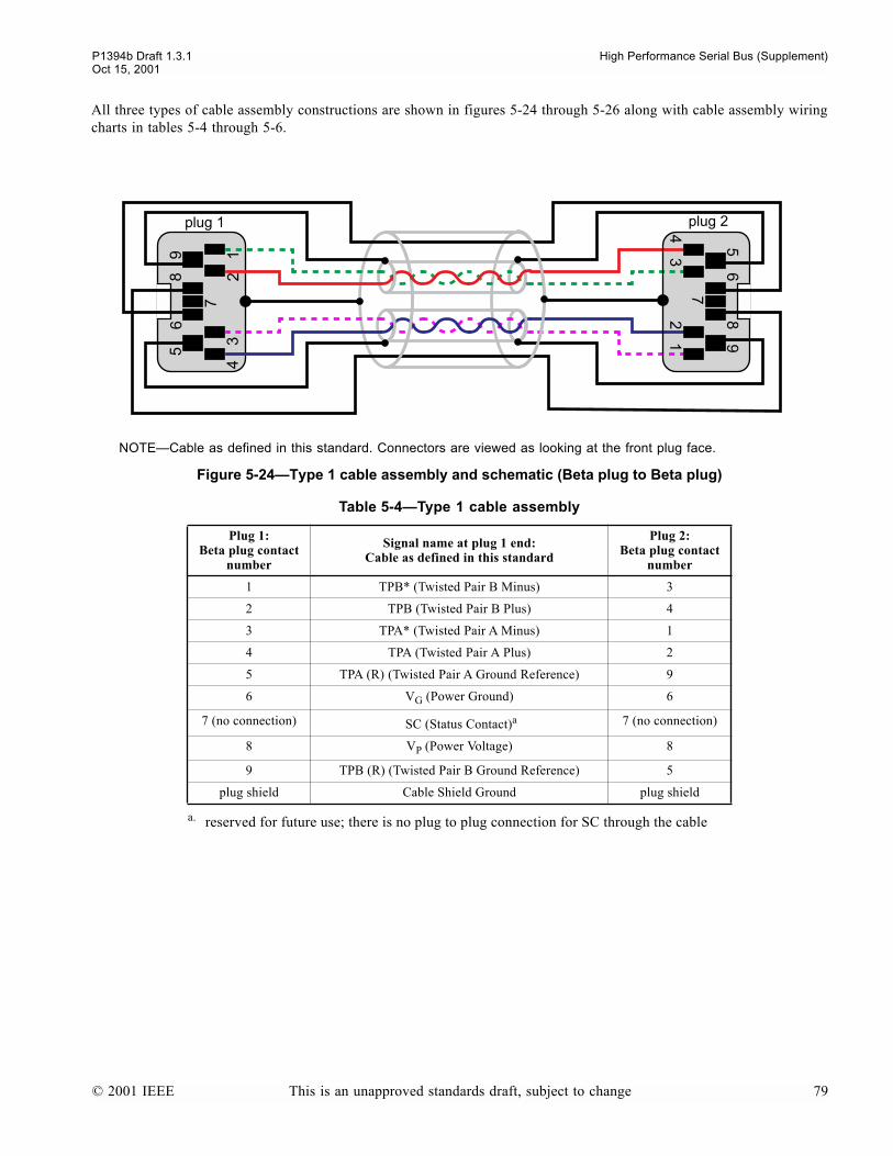
P1394b Draft 1.3.1 High Performance Serial Bus (Supplement)Oct 15, 2001
All three types of cable assembly constructions are shown in figures 5-24 through 5-26 along with cable assembly wiringcharts in tables 5-4 through 5-6.
NOTECable as defined in this standard. Connectors are viewed as looking at the front plug face.
Figure 5-24Type 1 cable assembly and schematic (Beta plug to Beta plug)
Table 5-4Type 1 cable assembly
Plug 1:Beta plug contact
number
Signal name at plug 1 end:Cable as defined in this standard
Plug 2:Beta plug contact
number
1 TPB* (Twisted Pair B Minus) 3
2 TPB (Twisted Pair B Plus) 4
3 TPA* (Twisted Pair A Minus) 1
4 TPA (Twisted Pair A Plus) 2
5 TPA (R) (Twisted Pair A Ground Reference) 9
6 VG (Power Ground) 6
7 (no connection) SC (Status Contact)a
a. reserved for future use; there is no plug to plug connection for SC through the cable
7 (no connection)
8 VP (Power Voltage) 8
9 TPB (R) (Twisted Pair B Ground Reference) 5
plug shield Cable Shield Ground plug shield
74
32
1
56
89
74
32
1
56
89
plug 1 plug 2
© 2001 IEEE This is an unapproved standards draft, subject to change 79
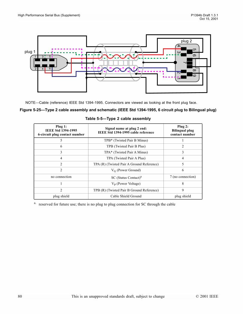
High Performance Serial Bus (Supplement) P1394b Draft 1.3.1Oct 15, 2001
NOTECable (reference) IEEE Std 1394-1995. Connectors are viewed as looking at the front plug face.
Figure 5-25Type 2 cable assembly and schematic (IEEE Std 1394-1995, 6 circuit plug to Bilingual plug)
Table 5-5Type 2 cable assembly
Plug 1:IEEE Std 1394-1995
6-circuit plug contact number
Signal name at plug 2 end:IEEE Std 1394-1995 cable reference
Plug 2:Bilingual plug
contact number
5 TPB* (Twisted Pair B Minus) 1
6 TPB (Twisted Pair B Plus) 2
3 TPA* (Twisted Pair A Minus) 3
4 TPA (Twisted Pair A Plus) 4
2 TPA (R) (Twisted Pair A Ground Reference) 5
2 VG (Power Ground) 6
no connection SC (Status Contact)a 7 (no connection)
1 VP (Power Voltage) 8
2 TPB (R) (Twisted Pair B Ground Reference) 9
plug shield Cable Shield Ground plug shield
a. reserved for future use; there is no plug to plug connection for SC through the cable
4
3
2
1 5
6
74
32
1
56
89
plug 1
plug 2
80 This is an unapproved standards draft, subject to change © 2001 IEEE
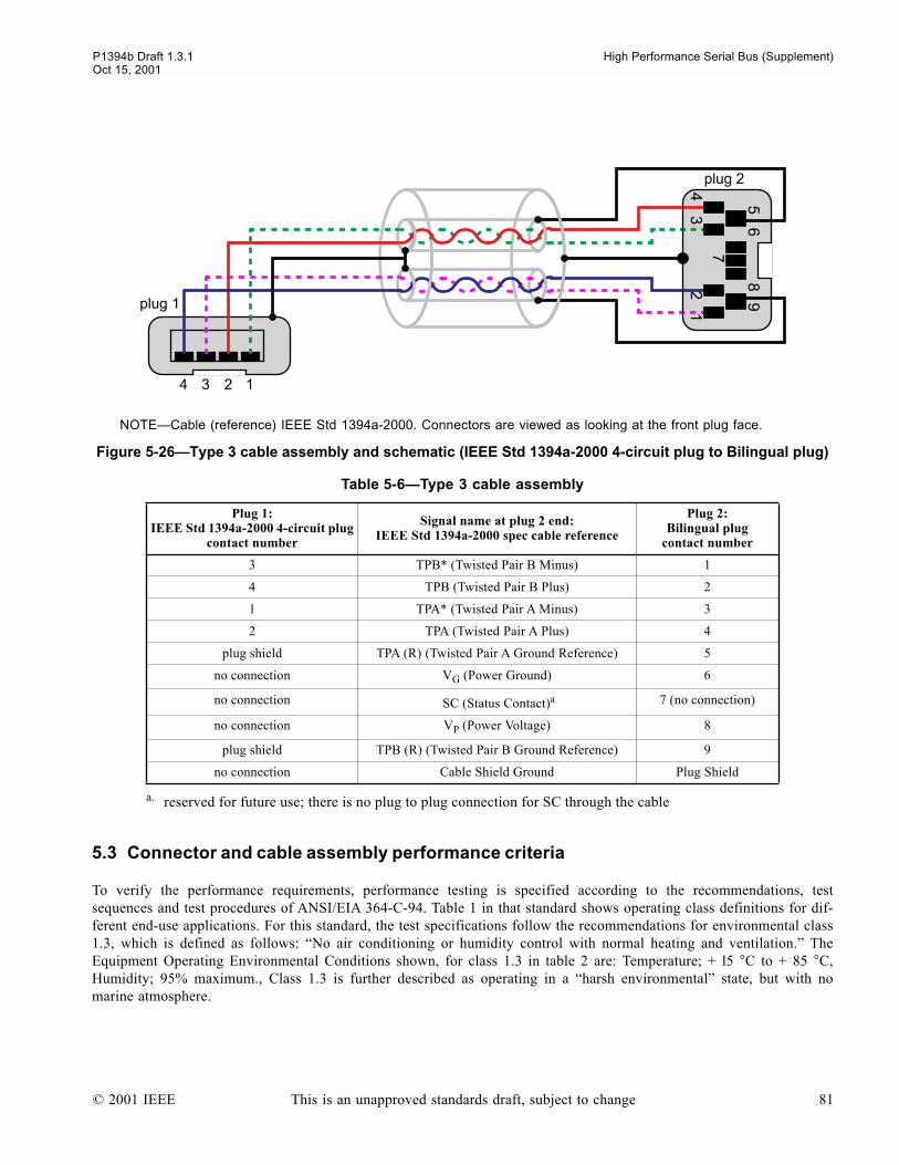
P1394b Draft 1.3.1 High Performance Serial Bus (Supplement)Oct 15, 2001
5.3 Connector and cable assembly performance criteria
To verify the performance requirements, performance testing is specified according to the recommendations, testsequences and test procedures of ANSI/EIA 364-C-94. Table 1 in that standard shows operating class definitions for dif-ferent end-use applications. For this standard, the test specifications follow the recommendations for environmental class1.3, which is defined as follows: No air conditioning or humidity control with normal heating and ventilation. TheEquipment Operating Environmental Conditions shown, for class 1.3 in table 2 are: Temperature; + l5 °C to + 85 °C,Humidity; 95% maximum., Class 1.3 is further described as operating in a harsh environmental state, but with nomarine atmosphere.
NOTECable (reference) IEEE Std 1394a-2000. Connectors are viewed as looking at the front plug face.
Figure 5-26Type 3 cable assembly and schematic (IEEE Std 1394a-2000 4-circuit plug to Bilingual plug)
Table 5-6Type 3 cable assembly
Plug 1:IEEE Std 1394a-2000 4-circuit plug
contact number
Signal name at plug 2 end:IEEE Std 1394a-2000 spec cable reference
Plug 2:Bilingual plug
contact number
3 TPB* (Twisted Pair B Minus) 1
4 TPB (Twisted Pair B Plus) 2
1 TPA* (Twisted Pair A Minus) 3
2 TPA (Twisted Pair A Plus) 4
plug shield TPA (R) (Twisted Pair A Ground Reference) 5
no connection VG (Power Ground) 6
no connection SC (Status Contact)a
a. reserved for future use; there is no plug to plug connection for SC through the cable
7 (no connection)
no connection VP (Power Voltage) 8
plug shield TPB (R) (Twisted Pair B Ground Reference) 9
no connection Cable Shield Ground Plug Shield
4 3 2 1
plug 1
74
32
1
56
89
plug 2
© 2001 IEEE This is an unapproved standards draft, subject to change 81
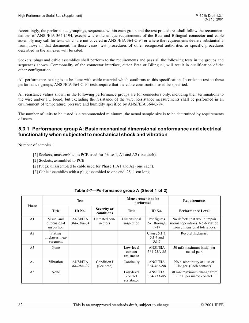
High Performance Serial Bus (Supplement) P1394b Draft 1.3.1Oct 15, 2001
Accordingly, the performance groupings, sequences within each group and the test procedures shall follow the recommen-dations of ANSI/EIA 364-C-94, except where the unique requirements of the Beta and Bilingual connector and cableassembly may call for tests which are not covered in ANSI/EIA 364-C-94 or where the requirements deviate substantiallyfrom those in that document. In those cases, test procedures of other recognized authorities or specific proceduresdescribed in the annexes will be cited.
Sockets, plugs and cable assemblies shall perform to the requirements and pass all the following tests in the groups andsequences shown. Commonality of the connector interface, either Beta or Bilingual, will result in qualification of theother configuration.
All performance testing is to be done with cable material which conforms to this specification. In order to test to theseperformance groups, ANSI/EIA 364-C-94 tests require that the cable construction used be specified.
All resistance values shown in the following performance groups are for connectors only, including their terminations tothe wire and/or PC board, but excluding the resistance of the wire. Resistance measurements shall be performed in anenvironment of temperature, pressure and humidity specified by ANSI/EIA 364-C-94.
The number of units to be tested is a recommended minimum; the actual sample size is to be determined by requirementsof users.
5.3.1 Performance group A: Basic mechanical dimensional conformance and electrical functionality when subjected to mechanical shock and vibration
Number of samples:
[2] Sockets, unassembled to PCB used for Phase 1, A1 and A2 (one each).[2] Sockets, assembled to PCB[2] Plugs, unassembled to cable used for Phase 1, A1 and A2 (one each).[2] Cable assemblies with a plug assembled to one end, 25±1 cm long.
Table 5-7Performance group A (Sheet 1 of 2)
PhaseTest Measurements to be
performed Requirements
Title ID No. Severity or conditions Title ID No. Performance Level
A1 Visual and dimensional inspection
ANSI/EIA 364-18A-84
Unmated con-nectors
Dimensional inspection
Per figures5-1 through
5-17
No defects that would impair normal operations. No deviation
from dimensional tolerances.
A2 Plating thickness mea-
surement
Clause 5.1.3, 5.1.4 and
5.1.5
Record thickness;
A3 None Low-level contact
resistance
ANSI/EIA 364-23A-85
50 mΩ maximum initial per mated pair.
A4 Vibration ANSI/EIA 364-28D-99
Condition I(See note)
Continuity ANSI/EIA 364-46A-98
No discontinuity at 1 µs or longer. (Each contact)
A5 None Low-level contact
resistance
ANSI/EIA 364-23A-85
30 mΩ maximum change from initial per mated contact.
82 This is an unapproved standards draft, subject to change © 2001 IEEE
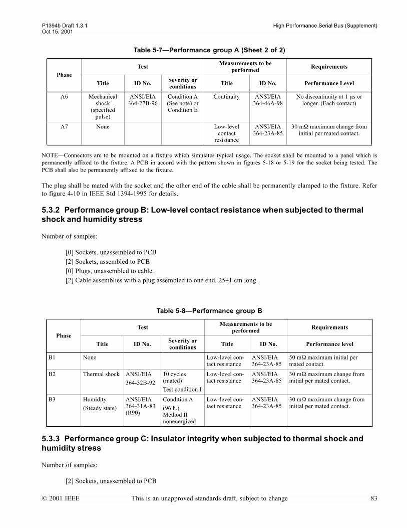
P1394b Draft 1.3.1 High Performance Serial Bus (Supplement)Oct 15, 2001
NOTEConnectors are to be mounted on a fixture which simulates typical usage. The socket shall be mounted to a panel which ispermanently affixed to the fixture. A PCB in accord with the pattern shown in figures 5-18 or 5-19 for the socket being tested. ThePCB shall also be permanently affixed to the fixture.
The plug shall be mated with the socket and the other end of the cable shall be permanently clamped to the fixture. Referto figure 4-10 in IEEE Std 1394-1995 for details.
5.3.2 Performance group B: Low-level contact resistance when subjected to thermal shock and humidity stress
Number of samples:
[0] Sockets, unassembled to PCB[2] Sockets, assembled to PCB[0] Plugs, unassembled to cable.[2] Cable assemblies with a plug assembled to one end, 25±1 cm long.
5.3.3 Performance group C: Insulator integrity when subjected to thermal shock and humidity stress
Number of samples:
[2] Sockets, unassembled to PCB
A6 Mechanical shock
(specified pulse)
ANSI/EIA 364-27B-96
Condition A(See note) or Condition E
Continuity ANSI/EIA 364-46A-98
No discontinuity at 1 µs or longer. (Each contact)
A7 None Low-level contact
resistance
ANSI/EIA 364-23A-85
30 mΩ maximum change from initial per mated contact.
Table 5-8Performance group B
PhaseTest Measurements to be
performed Requirements
Title ID No. Severity or conditions Title ID No. Performance level
B1 None Low-level con-tact resistance
ANSI/EIA 364-23A-85
50 mΩ maximum initial per mated contact.
B2 Thermal shock ANSI/EIA
364-32B-92
10 cycles (mated)
Test condition I
Low-level con-tact resistance
ANSI/EIA 364-23A-85
30 mΩ maximum change from initial per mated contact.
B3 Humidity
(Steady state)
ANSI/EIA 364-31A-83(R90)
Condition A
(96 h.)Method II nonenergized
Low-level con-tact resistance
ANSI/EIA 364-23A-85
30 mΩ maximum change from initial per mated contact.
Table 5-7Performance group A (Sheet 2 of 2)
PhaseTest Measurements to be
performed Requirements
Title ID No. Severity or conditions Title ID No. Performance Level
© 2001 IEEE This is an unapproved standards draft, subject to change 83
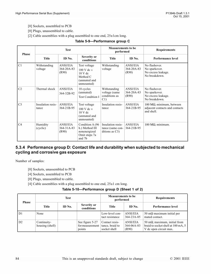
High Performance Serial Bus (Supplement) P1394b Draft 1.3.1Oct 15, 2001
[0] Sockets, assembled to PCB[0] Plugs, unassembled to cable.[2] Cable assemblies with a plug assembled to one end, 25±1cm long.
5.3.4 Performance group D: Contact life and durability when subjected to mechanical cycling and corrosive gas exposure
Number of samples:
[0] Sockets, unassembled to PCB[4] Sockets, assembled to PCB[0] Plugs, unassembled to cable.[4] Cable assemblies with a plug assembled to one end, 25±1 cm long.
Table 5-9Performance group C
PhaseTest Measurements to be
performed Requirements
Title ID No. Severity or conditions Title ID No. Performance level
C1 Withstanding voltage
ANSI/EIA 364-20A-83(R90)
Test voltage
100 V dc ±10 V dcMethod C (unmated and unmounted)
Withstanding voltage
ANSI/EIA 364-20A-83(R90)
No flashover.No sparkover.No excess leakage.No breakdown.
C2 Thermal shock ANSI/EIA
364-32B-92
10 cycles (unmated)
Test Condition I
Withstanding voltage (same conditions as C1)
ANSI/EIA 364-20A-83(R90)
No flashover.No sparkover.No excess leakage.No breakdown.
C3 Insulation resis-tance
ANSI/EIA 364-21B-95
Test voltage
100 V dc ±10 V dc(unmated and unmounted)
Insulation resis-tance
ANSI/EIA 364-21B-95
100 ΜΩ, minimum, between adjacent contacts and contacts and shell.
C4 Humidity (cyclic)
ANSI/EIA 364-31A-83(R90)
Condition A (96 h.) Method III nonenergizedOmit steps 7a and 7b
Insulation resis-tance (same con-ditions as C3)
ANSI/EIA 364-21B-95
100 ΜΩ, minimum.
Table 5-10Performance group D (Sheet 1 of 2)
PhaseTest Measurements to be
performed Requirements
Title ID No. Severity or conditions Title ID No. Performance level
D1 None Low-level con-tact resistance
ANSI/EIA 364-23A-85
50 mΩ maximum initial per mated contact.
D2 Continuity-housing (shell)
See figure 5-27 for measurement points
Contact resis-tance, braid to socket shell
ANSI/EIA 364-06A-83(R90)
50 mΩ, maximum, initial from braid to socket shell at 100 mA, 5 V dc open circuit max.
84 This is an unapproved standards draft, subject to change © 2001 IEEE

P1394b Draft 1.3.1 High Performance Serial Bus (Supplement)Oct 15, 2001
D3 Durability ANSI/EIA 364-09B-91
(a) 2 mated pairs, 5 cycles
(b) 2 mated pairs, automatic cycling to 500 cycles, rate 500 cycles/h ±50 cycles.
D4 None Low-level contact resistance
ANSI/EIA 364-23A-85
30 mΩ maximum change from initial per mated contact.
D5 Continuity-housing (shell)
See figure 5-27 for measurement points
Contact resistance
ANSI/EIA 364-06A-83(R90)
50 mΩ maximum change from initial from braid to socket shell.
100 mA, 5V dc open circuit max.
D6 Mixed flowing gas
ANSI/EIA 364-65A-97
Class II Expo-sures:
(a) 2 mated pairs - unmated for 1 day
(b) 2 mated pairs - Mated 10 days
Low level contact resistance
ANSI/EIA 364-23A-85
30 mΩ maximum change from initial per mated contact.
D7 Durability ANSI/EIA 364-09B-91
(a) 2 mated pairs, 5 cycles
(b) 2 mated pairs, automatic cycling to 500 cycles, rate 500 cycles/h ±50 cycles
D8 Mixed flowing gas
ANSI/EIA 364-65A-97
Class IIExposures:Expose mated for 10 day
Low level contact resistance at end of exposure
ANSI/EIA 364-23A-85
30 mΩ maximum change from initial per mated contact.
D9 Continuity-housing (shell)
See figure 5-27 for measurement points
Contact resistance
ANSI/EIA 364-06A-83(R90)
50 mΩ maximum change from initial from braid to socket shell.
100 mA, 5V dc open circuit max.
Table 5-10Performance group D (Sheet 2 of 2)
PhaseTest Measurements to be
performed Requirements
Title ID No. Severity or conditions Title ID No. Performance level
© 2001 IEEE This is an unapproved standards draft, subject to change 85

High Performance Serial Bus (Supplement) P1394b Draft 1.3.1Oct 15, 2001
5.3.5 Performance group E: Contact resistance and unmating force when subjected to temperature life stress
Number of samples:
[0] Sockets, unassembled to PCB[2] Sockets, assembled to PCB[0] Plugs, unassembled to cable.
Figure 5-27Shield and contact resistance measuring points
PWB Socket Plug Cable
a) contact resistance
Wire I
V
I V
Wire termination
X
Note: subtract bulk wire resistance of length "X" from measurement
PWB Socket Plug Cable
I V
I
V
b)shield resistance [inner shield contacts #10 and #11 to external cable shield]
86 This is an unapproved standards draft, subject to change © 2001 IEEE

P1394b Draft 1.3.1 High Performance Serial Bus (Supplement)Oct 15, 2001
[2] Cable assemblies with a plug assembled to one end, 25±1cm long.
5.3.6 Performance group F: Mechanical retention and durability
Number of samples:
[0] Sockets, unassembled to PCB[2] Sockets, assembled to PCB[0] Plugs, unassembled to cable.[2] Plugs, assembled to cable, one end only, 25±1 cm long.
Table 5-11Performance group E
PhaseTest Measurements to be
performed Requirements
Title ID No. Severity or conditions Title ID No. Performance level
E1 Mating and unmating forces
ANSI/EIA 364-13A-83(R90)
Mount socket rigidly. Insert receptacle by hand.
Mating only
Auto Rate: 25 mm/min
Unmating only ANSI/EIA 364-13A-83(R90)
Unmating force: 10.0 N minimum39.0 N maximum
E2 None Low-level contact resistance
ANSI/EIA 364-23A-85
50 mΩ maximum initial per mated contact.
E3 Continuity-housing (shell)
See figure 5-27 Contact resistance
ANSI/EIA 364-06A-83(R90)
50 mΩ maximum initial from braid to socket shell. 100 mA, 5 V dc open circuit max.
E4 Temperature life
ANSI/EIA 364-17B-99
Condition 2 (79° C) 96 hoursMethod A (mated)
Low-level contact resistance
ANSI/EIA 364-23A-85
30 mΩ maximum change from initial per mated contact.
E5 Continuity-housing (shell)
Contact resistance
ANSI/EIA 364-06A-83(R90)
50 mΩ maximum change from initial from braid to socket shell.
E6 Mating and unmating forces
ANSI/EIA 364-13A-83(R90)
Mount socket rigidly. Insert plug by hand.
Mating only
Unmating only ANSI/EIA 364-13A-83(R90)
Unmating force: 10.0 N minimum39.0 N maximum
© 2001 IEEE This is an unapproved standards draft, subject to change 87

High Performance Serial Bus (Supplement) P1394b Draft 1.3.1Oct 15, 2001
5.3.7 Performance group G: General tests
Suggested procedures to test miscellaneous but important aspects of the interconnect.
Since the tests listed below may be destructive, separate samples should be used for each test. The number of samples tobe used is listed under the test title.
Table 5-12Performance group F
PhaseTest Measurements to be
performed Requirements
Title ID No. Severity or conditions Title ID No. Performance level
F1 Mating and unmating forces
ANSI/EIA 364-13A-83(R90)
Mount socket rigidly. Insert plug by hand.
Mating only
F2 Mating and unmating forces
ANSI/EIA 364-13A-83(R90)
Auto rate: 25 mm/min
Unmating only ANSI/EIA 364-13A-83(R90)
Unmating force: 10.0 N minimum39.0 N maximum
F3 Durability ANSI/EIA 364-09C-99
Automatic cycling to 1000 cycles. 500 cycles/h ±50 cycles
Unmating only ANSI/EIA 364-13A-83(R90)
Unmating force at end of durability cycles: 10.0 N minimum39.0 N maximum
Table 5-13Performance group G
PhaseTest Measurements to be performed Requirements
Title ID No. Severity or conditions Title ID No. Performance level
G1 Electrostatic Discharge
[1 plug]
[1 socket]
IEC 61000-4-2
(1999-05)
1 to 8 kV in 1 kV steps. Use 8 mm ball probe. Test unmated.
Evidence of dis-charge
No evidence of discharge to any of the 9 contacts; discharge to shield is acceptable.
G2 Cable axial pull test.
[2 plugs]
ANSI/EIA
364-38A-85
Fix plug housing and apply a 50.0 N load for one minute on cable axis.
Continuity, visual ANSI/EIA 364-46A-98
No discontinuity on contacts or shield greater than 1 µs under load. No jacket tears or visual exposure of shield. No jacket movement greater than 1.5 mm at point of exit.
G3 Cable flexing
[2 plugs]
ANSI/EIA 364-41B-89
Condition I, dimension X=5.5 x cable diameter; 100 cycles in each of two planes
See Figure 5-28
(a) Withstanding voltage
Per C1 Per C1
(b) Insulation resistance
Per C3 Per C3
(c) Continuity ANSI/EIA 364-46A-98
No discontinuity on contacts or shield greater than 1 µs during flex-ing.
(d) Visual - No jacket tears or visual exposure of shield. No jacket movement greater than 1.5 mm at point of exit.
88 This is an unapproved standards draft, subject to change © 2001 IEEE
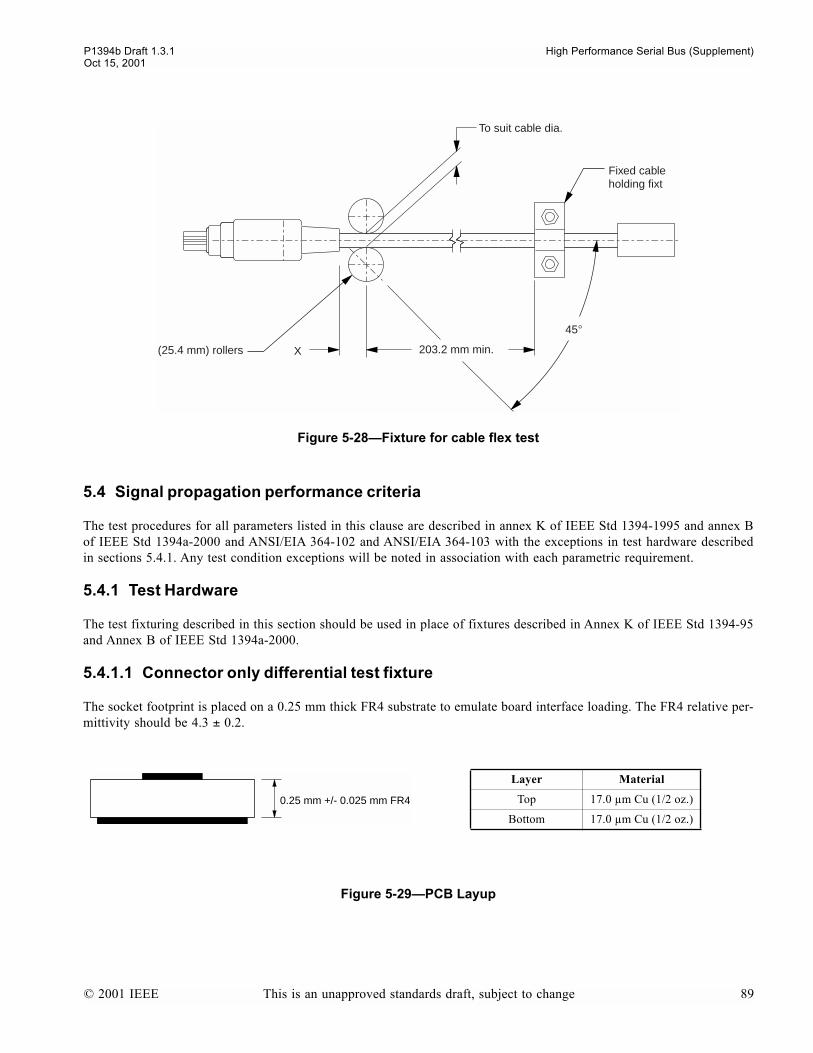
P1394b Draft 1.3.1 High Performance Serial Bus (Supplement)Oct 15, 2001
5.4 Signal propagation performance criteria
The test procedures for all parameters listed in this clause are described in annex K of IEEE Std 1394-1995 and annex Bof IEEE Std 1394a-2000 and ANSI/EIA 364-102 and ANSI/EIA 364-103 with the exceptions in test hardware describedin sections 5.4.1. Any test condition exceptions will be noted in association with each parametric requirement.
5.4.1 Test Hardware
The test fixturing described in this section should be used in place of fixtures described in Annex K of IEEE Std 1394-95and Annex B of IEEE Std 1394a-2000.
5.4.1.1 Connector only differential test fixture
The socket footprint is placed on a 0.25 mm thick FR4 substrate to emulate board interface loading. The FR4 relative per-mittivity should be 4.3 ± 0.2.
Figure 5-28Fixture for cable flex test
Figure 5-29PCB Layup
(25.4 mm) rollers
45°
203.2 mm min.
To suit cable dia.
Fixed cableholding fixt
X
0.25 mm +/- 0.025 mm FR4
Layer Material
Top 17.0 µm Cu (1/2 oz.)
Bottom 17.0 µm Cu (1/2 oz.)
© 2001 IEEE This is an unapproved standards draft, subject to change 89
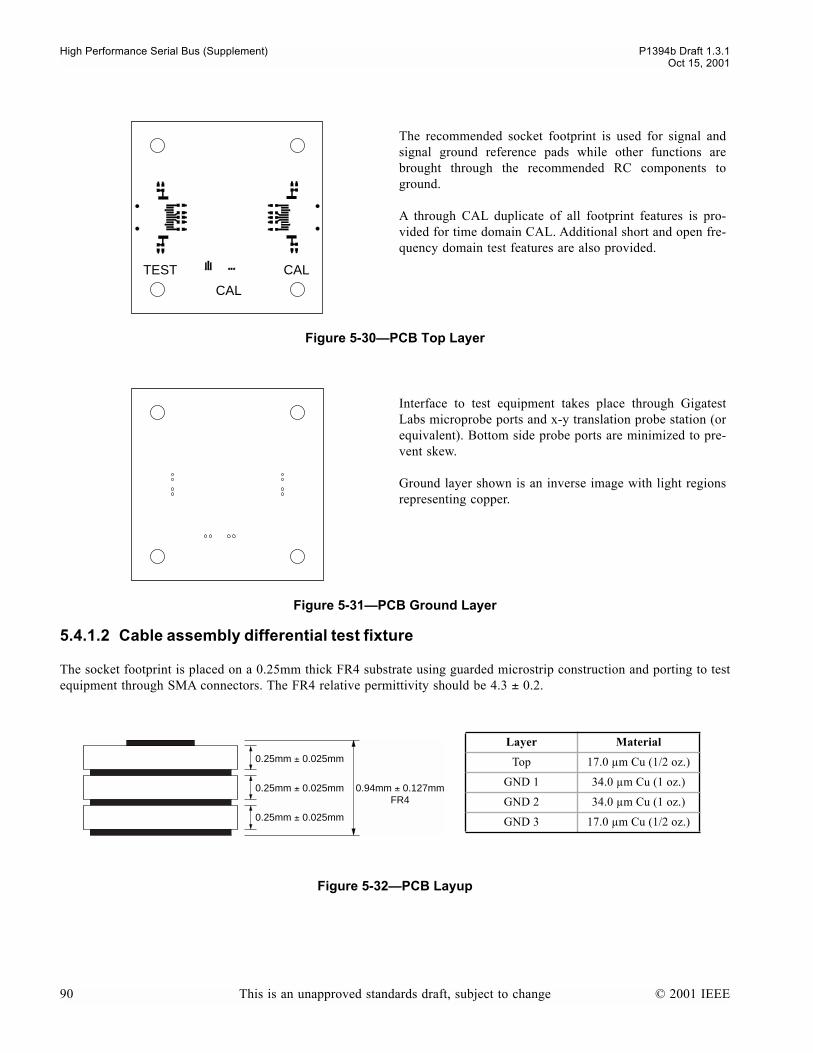
High Performance Serial Bus (Supplement) P1394b Draft 1.3.1Oct 15, 2001
5.4.1.2 Cable assembly differential test fixture
The socket footprint is placed on a 0.25mm thick FR4 substrate using guarded microstrip construction and porting to testequipment through SMA connectors. The FR4 relative permittivity should be 4.3 ± 0.2.
The recommended socket footprint is used for signal andsignal ground reference pads while other functions arebrought through the recommended RC components toground.
A through CAL duplicate of all footprint features is pro-vided for time domain CAL. Additional short and open fre-quency domain test features are also provided.
Figure 5-30PCB Top Layer
Interface to test equipment takes place through GigatestLabs microprobe ports and x-y translation probe station (orequivalent). Bottom side probe ports are minimized to pre-vent skew.
Ground layer shown is an inverse image with light regionsrepresenting copper.
Figure 5-31PCB Ground Layer
Figure 5-32PCB Layup
CAL
CAL
TEST
0.25mm ± 0.025mm
0.25mm ± 0.025mm 0.94mm ± 0.127mmFR4
0.25mm ± 0.025mm
Layer Material
Top 17.0 µm Cu (1/2 oz.)
GND 1 34.0 µm Cu (1 oz.)
GND 2 34.0 µm Cu (1 oz.)
GND 3 17.0 µm Cu (1/2 oz.)
90 This is an unapproved standards draft, subject to change © 2001 IEEE

P1394b Draft 1.3.1 High Performance Serial Bus (Supplement)Oct 15, 2001
The recommended socket footprint is used with signalpositions routed to SMA connectors through 55 ohm ± 5%traces.
All functions other than signal and signal ground referenceare brought through the recommended RC components toground.
A through CAL duplicate of all footprint features is pro-vided for time domain CAL. This includes a mirror imagedfar end pattern to duplicate the hardware burden of a com-plete link.
Figure 5-33PCB Top Layer
Layers GND1, GND2 and GND3 are identical. Pinningvias should be installed regularly about signal traces to tieall ground planes together.
Ground layer shown is an inverse image with light regionsrepresenting copper.
Figure 5-34PCB Ground Layer
CAL TEST
© 2001 IEEE This is an unapproved standards draft, subject to change 91
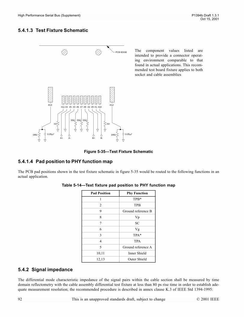
High Performance Serial Bus (Supplement) P1394b Draft 1.3.1Oct 15, 2001
5.4.1.3 Test Fixture Schematic
5.4.1.4 Pad position to PHY function map
The PCB pad positions shown in the test fixture schematic in figure 5-35 would be routed to the following functions in anactual application.
5.4.2 Signal impedance
The differential mode characteristic impedance of the signal pairs within the cable section shall be measured by timedomain reflectometry with the cable assembly differential test fixture at less than 80 ps rise time in order to establish ade-quate measurement resolution; the recommended procedure is described in annex clause K.3 of IEEE Std 1394-1995:
The component values listed areintended to provide a connector operat-ing environment comparable to thatfound in actual applications. This recom-mended test board fixture applies to bothsocket and cable assemblies
Figure 5-35Test Fixture Schematic
Table 5-14Text fixture pad position to PHY function map
Pad Position Phy Function
1 TPB*
2 TPB
9 Ground reference B
8 Vp
7 SC
6 Vg
3 TPA*
4 TPA
5 Ground reference A
10,11 Inner Shield
12,13 Outer Shield
#12#10
1Ω
33Ω33Ω33Ω
1Ω
0.05µF1MΩ
#1#7 #8 #2
B-
PCB EDGE
B+
#9#6#3#5#4
A-A+
#11
0.05µF1MΩ
#13
92 This is an unapproved standards draft, subject to change © 2001 IEEE

P1394b Draft 1.3.1 High Performance Serial Bus (Supplement)Oct 15, 2001
ZTPA = (110 ± 6) Ω (differential)ZTPB = (110 ± 6) Ω (differential)
The common mode characteristic impedance of the signal pairs within the cable section shall be measured by time domainreflectometry with the cable assembly differential test fixture at less than 80 ps rise time in order to establish adequatemeasurement resolution; the recommended procedure is described in annex clause K.3 of IEEE Std 1394-1995:
ZTPACM = (33 ± 6) Ω (common mode)ZTPBCM = (33 ± 6) Ω (common mode)
The differential mode discrete impedance of the signal pairs within the mated connector section shall be measured bytime domain reflectometry with the connector only differential test fixture at an 80 ps rise time. The recommended proce-dure is described in annex clause B.2 of IEEE Std 1394a-2000 with the following exception in test condition; evaluatedifferential impedance over a 150 ps exception window with test points at;
1) connector insertion plane - 25 ps2) connector insertion plane (reference point, so offset will be 0 ps)3) connector insertion plane + 50 ps4) connector insertion plane + 100 ps5) connector insertion plane + 125 ps
The exception window is extended ± 25 ps beyond the beginning and end of a typical mated connector in order to evalu-ate settling performance. Also note that in making time domain measurements multiply all real time values above by 2xto account for the round trip.
ZTPACONN = (110 ± 20) Ω (differential)ZTPBCONN = (110 ± 20) Ω (differential)
5.4.3 Signal pairs attenuation
A signal pairs attenuation requirement applies only to the two signal pairs, for any given cable assembly. Attenuation ismeasured using the procedure described in annex K.4 of IEEE Std 1394-1995. A connector insertion loss value is allowedin order to de-embed cable only attenuation from measured connector/cable assemblies. The connector allowance listed isfor two mated connectors, one at the assembly input and one at the output. Connector/cable assemblies shall be sweptthrough the frequencies listed with the stop frequency at 1000 MHz. Curves shall be smooth with no anomalous behavior..
5.4.4 Signal pairs velocity of propagation
The maximum differential propagation delay of the signal pairs through the cable shall be measured in the frequencydomain; the recommended procedure is described in annex clause K.5 of IEEE Std 1394-1995:
VTPA ≤ 5.05 ns/mVTPB ≤ 5.05 ns/m
Frequency Cable Attenuation Connector Allowance Total Allowance
250 MHz ≤ 2.30 dB 1.00 dB ≤ 3.30 dB
400 MHz ≤ 2.90 dB 1.20 dB ≤ 4.10 dB
500 MHz ≤ 3.50 dB 1.35 dB ≤ 4.85 dB
800 MHz ≤ 4.60 dB 1.60 dB ≤ 6.20 dB
1000 MHz ≤ 5.50 dB 2.00 dB ≤ 7.50 dB
© 2001 IEEE This is an unapproved standards draft, subject to change 93

High Performance Serial Bus (Supplement) P1394b Draft 1.3.1Oct 15, 2001
The common mode propagation delay of the signal pairs shall be less than or equal to the differential propagation delay.For typical cable constructions this is correct by design; consequently no test procedure is described for this in eitherannex K.5 of IEEE Std 1394-1995, or annex B of IEEE Std 1394a-2000:
VTPACM ≤ 5.05 ns/mVTPBCM ≤ 5.05 ns/m
5.4.5 Signal pairs risetime degradation
The differential risetime degradation shall be measured through the mated connector section using a differential TDT withan injected risetime of 70 ps or less to establish sufficient measurement resolution. The recommended procedure isdescribed within ANSI/EIA 364-102 using the connector only differential test fixture.
trise TPA ≤ 100pstrise TPB ≤ 100ps
5.4.6 Signal pairs intra-pair propagation skew
The maximum difference between the differential mode propagation delay within the differential twisted pairs shall bemeasured in the time domain with injected risetime of 70 ps or less through the connector/cable assembly for a 4.5 meterlength. The recommended procedure is described within ANSI/EIA 364-103 using the cable assembly differential test fix-ture:
SIP assembly ≤ 160ps
The connector only skew measured with the connector only differential test fixture with an injected risetime of 70 ps orless shall be:
Intrapaircon < 10psInterpaircon < 15ps
5.4.7 Crosstalk
5.4.7.1 Connector
The TPA-TPB signal to signal crosstalk shall be measured within the mated connector section in the time domain usingthe connector only differential test fixture and a differential TDT at 80 ps (10%-90%) to emulate operation of the matedconnector at S3200 operation. All transmit and receive ports are sourced and terminated respectively with 50Ω loads.
XNEXT, XFEXT ≤ 3%
5.4.7.2 Cable Assembly
The TPA-TPB signal to signal crosstalk shall be measured within a 4.5 meter cable assembly in the time domain using thecable assembly differential test fixture and a differential TDT at 160 ps (10%-90%) to emulate cable assembly at S1600operation. All transmit and receive ports are sourced and terminated respectively with 50Ω loads.
XNEXT, XFEXT≤ 5%
5.4.8 Power
The power pair conductor within the two specified Beta or Bilingual cable assemblies shall be capable of operating at 30V dc maximum and maintaining 1.5 A maximum operation continuously.
94 This is an unapproved standards draft, subject to change © 2001 IEEE
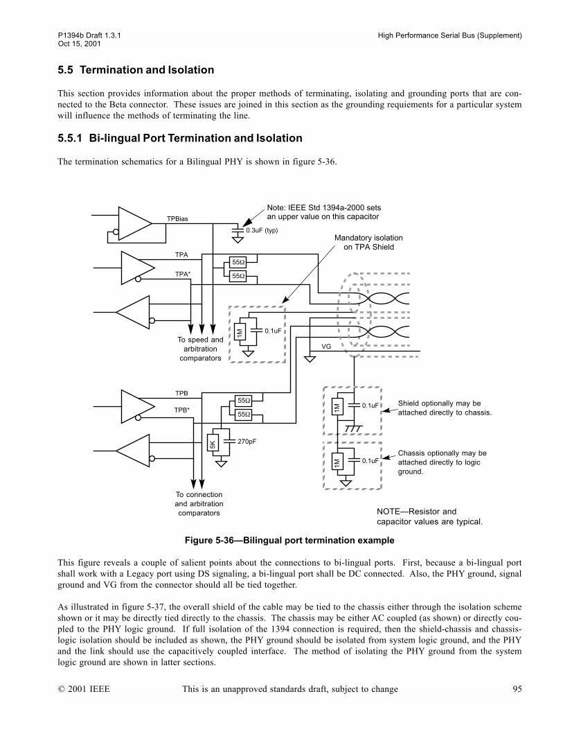
P1394b Draft 1.3.1 High Performance Serial Bus (Supplement)Oct 15, 2001
5.5 Termination and Isolation
This section provides information about the proper methods of terminating, isolating and grounding ports that are con-nected to the Beta connector. These issues are joined in this section as the grounding requiements for a particular systemwill influence the methods of terminating the line.
5.5.1 Bi-lingual Port Termination and Isolation
The termination schematics for a Bilingual PHY is shown in figure 5-36.
This figure reveals a couple of salient points about the connections to bi-lingual ports. First, because a bi-lingual portshall work with a Legacy port using DS signaling, a bi-lingual port shall be DC connected. Also, the PHY ground, signalground and VG from the connector should all be tied together.
As illustrated in figure 5-37, the overall shield of the cable may be tied to the chassis either through the isolation schemeshown or it may be directly tied directly to the chassis. The chassis may be either AC coupled (as shown) or directly cou-pled to the PHY logic ground. If full isolation of the 1394 connection is required, then the shield-chassis and chassis-logic isolation should be included as shown, the PHY ground should be isolated from system logic ground, and the PHYand the link should use the capacitively coupled interface. The method of isolating the PHY ground from the systemlogic ground are shown in latter sections.
Figure 5-36Bilingual port termination example
TPBias
TPA
TPA*
TPB
TPB*
VG
Mandatory isolationon TPA Shield
-
55Ω
0.3uF (typ)
55Ω
0.1uF
1M
55Ω
55Ω0.1uF
1M
Shield optionally may be attached directly to chassis.
0.1uF
1M
Chassis optionally may be attached directly to logic ground.
-
270pF
5K
To speed and arbitration
comparators
To connection and arbitration comparators NOTEResistor and
capacitor values are typical.
Note: IEEE Std 1394a-2000 sets an upper value on this capacitor
© 2001 IEEE This is an unapproved standards draft, subject to change 95

High Performance Serial Bus (Supplement) P1394b Draft 1.3.1Oct 15, 2001
In all Beta-capable nodes, it is required that the shield on the TPA (pin 5) be isolated from all local grounds as shown.This is to allow future versions of this specification to connect the Status Contact to the TPB shield ground for sensing ofcable capabilities.
5.5.2 Beta-only Port Termination and Isolation
The termination and grounding schemes for a Beta-only device are shown in figure 5-37 below.
As with the Bilingual connector, a Beta connector allows the chassis and PHY grounds to be either DC isolated as shownor to be directly connected. Also, isolation of the TPA(R) line is required.
The schematic shows the preferred placement of the capacitive isolation devices that are required on the TPA pair for allBeta-only ports. This isolation prevents the bias of the TPA pair from being sensed as a tpBias on a Legacy capable port.
There are multiple alternatives for terminating the TPB pair. A single 110Ω resistor, or a center-tapped pair may be usedto provide source impedance matching. If full-isolation of the PHY from the cable is required, then the shield-chassis iso-lation, chassis-logic isolation and 0.04µF capacitors should be used as shown. The capacitors are sized to give less than1% distortion of a worst case run length of 10 S400 bits (a 20ns pulse).
Figure 5-37 Beta-only connection to copper cable
TPA
TPA*
TPB
TPB*
Mandatory isolationon TPA Shield
-
55Ω
55Ω
0.1uF
1M
55Ω
55Ω
0.1uF
1M
Shield optionally may be attached directly to chassis.
0.1uF
1M
Chassis optionally may be attached directly to logic ground.
270pF
1M
270pF
1M
110
alternative termination for TPB
can be eliminated if decoupling capacitors
are in receiver
optional.04µF
.04µF
NOTEResistor and capacitor values are typical.
96 This is an unapproved standards draft, subject to change © 2001 IEEE
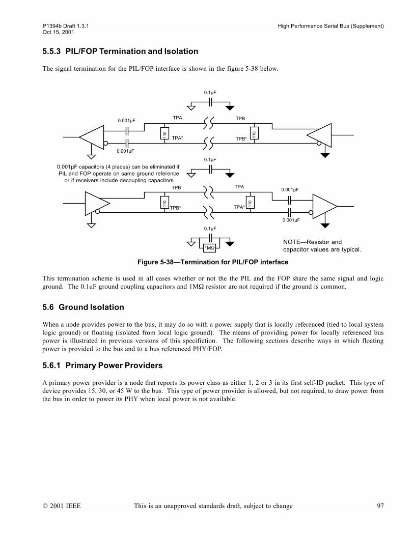
P1394b Draft 1.3.1 High Performance Serial Bus (Supplement)Oct 15, 2001
5.5.3 PIL/FOP Termination and Isolation
The signal termination for the PIL/FOP interface is shown in the figure 5-38 below.
This termination scheme is used in all cases whether or not the the PIL and the FOP share the same signal and logicground. The 0.1uF ground coupling capacitors and 1MΩ resistor are not required if the ground is common.
5.6 Ground Isolation
When a node provides power to the bus, it may do so with a power supply that is locally referenced (tied to local systemlogic ground) or floating (isolated from local logic ground). The means of providing power for locally referenced buspower is illustrated in previous versions of this specifiction. The following sections describe ways in which floatingpower is provided to the bus and to a bus referenced PHY/FOP.
5.6.1 Primary Power Providers
A primary power provider is a node that reports its power class as either 1, 2 or 3 in its first self-ID packet. This type ofdevice provides 15, 30, or 45 W to the bus. This type of power provider is allowed, but not required, to draw power fromthe bus in order to power its PHY when local power is not available.
Figure 5-38Termination for PIL/FOP interface
TPA
TPA*-
0.001µF capacitors (4 places) can be eliminated if PIL and FOP operate on same ground reference
or if receivers include decoupling capacitors
110
TPB*
TPB0.001µF
0.001µF
0.1µF
0.1µF
TPA
TPA*-
TPB*
TPB 0.001µF
0.001µF
0.1µF
1MΩ
110
110
110
NOTEResistor and capacitor values are typical.
© 2001 IEEE This is an unapproved standards draft, subject to change 97

High Performance Serial Bus (Supplement) P1394b Draft 1.3.1Oct 15, 2001
Figure 5-39 below, shows how the PHY/FOP electronics can be powered from either local or bus power, while figure 5-40 shows how the PHY/FOP power can be slightly simplified simplified if only powered locally.
Figure 5-39Providing power to a floating PHY/FOP, power class 1, 2 or 3
Figure 5-40Providing power to a floating PHY/FOP, power class 1, 2 or 3 (alternative)
6system logic ground
PHY/FOP logic ground
isolation and rectification
fuse or current limit to protect
against shorts
socket for port 0
VP
VG
TPA/B + R
6
socket for port 1
VP
VG
TPA/B + R
6
socket for port n
VP
VG
TPA/B + R
20-30 V dc in-put power
supply
IN
OUT
PHY/FOP electronics
20-30 V dc
6system logic ground
PHY/FOP logic ground
isolation and rectification
fuse or current limit to protect
against shorts
socket for port 0
VP
VG
TPA/B + R
6
socket for port 1
VP
VG
TPA/B + R
6
socket for port n
VP
VG
TPA/B + R
20-30 V dc in-put power
supply
IN
OUT
PHY/FOP electronics
20-30 V dc
98 This is an unapproved standards draft, subject to change © 2001 IEEE
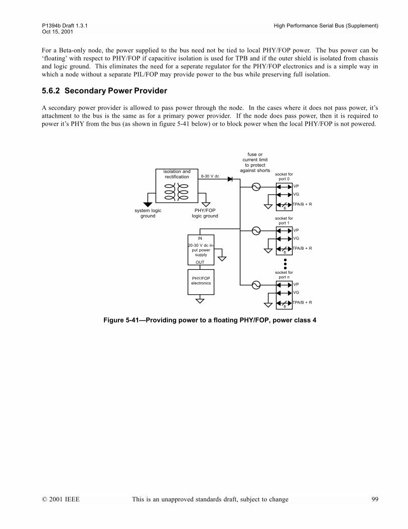
P1394b Draft 1.3.1 High Performance Serial Bus (Supplement)Oct 15, 2001
For a Beta-only node, the power supplied to the bus need not be tied to local PHY/FOP power. The bus power can befloating with respect to PHY/FOP if capacitive isolation is used for TPB and if the outer shield is isolated from chassisand logic ground. This eliminates the need for a seperate regulator for the PHY/FOP electronics and is a simple way inwhich a node without a separate PIL/FOP may provide power to the bus while preserving full isolation.
5.6.2 Secondary Power Provider
A secondary power provider is allowed to pass power through the node. In the cases where it does not pass power, itsattachment to the bus is the same as for a primary power provider. If the node does pass power, then it is required topower its PHY from the bus (as shown in figure 5-41 below) or to block power when the local PHY/FOP is not powered.
Figure 5-41Providing power to a floating PHY/FOP, power class 4
6system logic ground
PHY/FOP logic ground
isolation and rectification
fuse or current limit to protect
against shortssocket for
port 0
VP
VG
TPA/B + R
6
socket for port 1
VP
VG
TPA/B + R
6
socket for port n
VP
VG
TPA/B + R
20-30 V dc in-put power
supply
IN
OUT
PHY/FOP electronics
8-30 V dc
© 2001 IEEE This is an unapproved standards draft, subject to change 99

High Performance Serial Bus (Supplement) P1394b Draft 1.3.1Oct 15, 2001
100 This is an unapproved standards draft, subject to change © 2001 IEEE
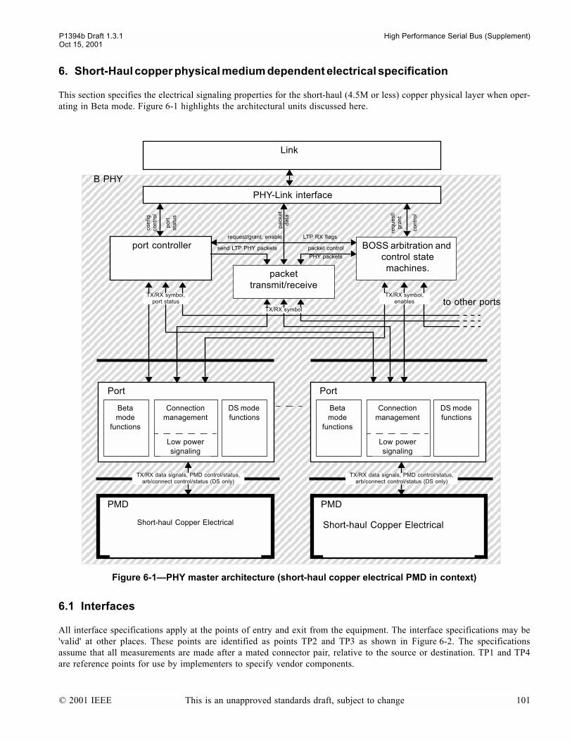
P1394b Draft 1.3.1 High Performance Serial Bus (Supplement)Oct 15, 2001
6. Short-Haul copper physical medium dependent electrical specification
This section specifies the electrical signaling properties for the short-haul (4.5M or less) copper physical layer when oper-ating in Beta mode. Figure 6-1 highlights the architectural units discussed here.
6.1 Interfaces
All interface specifications apply at the points of entry and exit from the equipment. The interface specifications may be'valid' at other places. These points are identified as points TP2 and TP3 as shown in Figure 6-2. The specificationsassume that all measurements are made after a mated connector pair, relative to the source or destination. TP1 and TP4are reference points for use by implementers to specify vendor components.
Figure 6-1PHY master architecture (short-haul copper electrical PMD in context)
BOSS arbitration and control state machines.
Short-haul Copper Electrical
Link
B PHY
PHY-Link interface
packet transmit/receive
port controller
DS mode functions
Beta mode
functions
Connection management
Low power signaling
Port
to other ports
pa
cke
t d
ata
send LTP PHY packets
req
ue
st\
gra
nt
packet control
request/grant, enable LTP RX flags
TX/RX symbol,port status
TX/RX symbol
TX/RX symbol,enables
con
tro
l
con
figco
ntr
ol
po
rtst
atu
s
PMD
Short-haul Copper Electrical
PMD
DS mode functions
Beta mode
functions
Connection management
Low power signaling
Port
PHY packets
TX/RX data signals, PMD control/status,arb/connect control/status (DS only)
TX/RX data signals, PMD control/status,arb/connect control/status (DS only)
© 2001 IEEE This is an unapproved standards draft, subject to change 101
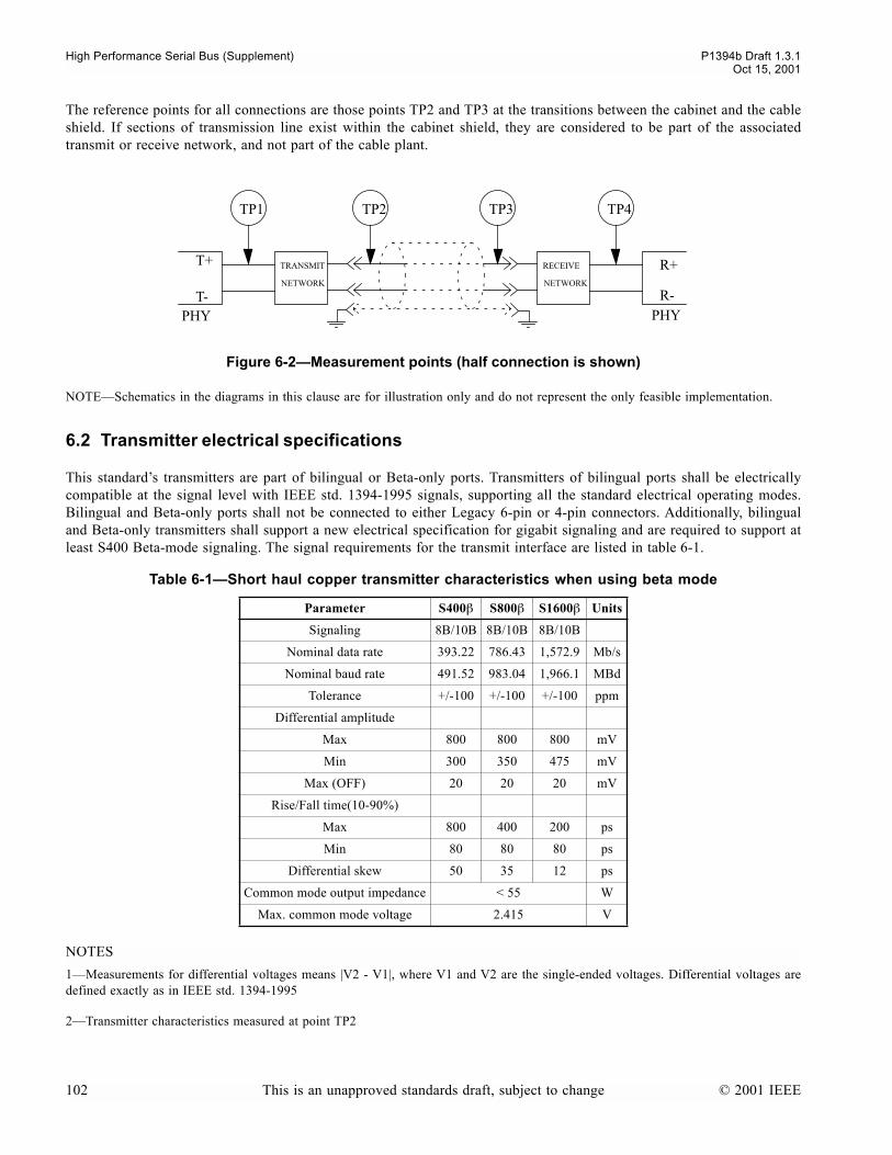
High Performance Serial Bus (Supplement) P1394b Draft 1.3.1Oct 15, 2001
The reference points for all connections are those points TP2 and TP3 at the transitions between the cabinet and the cableshield. If sections of transmission line exist within the cabinet shield, they are considered to be part of the associatedtransmit or receive network, and not part of the cable plant.
NOTESchematics in the diagrams in this clause are for illustration only and do not represent the only feasible implementation.
6.2 Transmitter electrical specifications
This standards transmitters are part of bilingual or Beta-only ports. Transmitters of bilingual ports shall be electricallycompatible at the signal level with IEEE std. 1394-1995 signals, supporting all the standard electrical operating modes.Bilingual and Beta-only ports shall not be connected to either Legacy 6-pin or 4-pin connectors. Additionally, bilingualand Beta-only transmitters shall support a new electrical specification for gigabit signaling and are required to support atleast S400 Beta-mode signaling. The signal requirements for the transmit interface are listed in table 6-1.
NOTES
1Measurements for differential voltages means |V2 - V1|, where V1 and V2 are the single-ended voltages. Differential voltages aredefined exactly as in IEEE std. 1394-1995
2Transmitter characteristics measured at point TP2
Figure 6-2Measurement points (half connection is shown)
Table 6-1Short haul copper transmitter characteristics when using beta mode
Parameter S400β S800β S1600β Units
Signaling 8B/10B 8B/10B 8B/10B
Nominal data rate 393.22 786.43 1,572.9 Mb/s
Nominal baud rate 491.52 983.04 1,966.1 MBd
Tolerance +/-100 +/-100 +/-100 ppm
Differential amplitude
Max 800 800 800 mV
Min 300 350 475 mV
Max (OFF) 20 20 20 mV
Rise/Fall time(10-90%)
Max 800 400 200 ps
Min 80 80 80 ps
Differential skew 50 35 12 ps
Common mode output impedance < 55 W
Max. common mode voltage 2.415 V
TRANSMIT
NETWORK
RECEIVE
NETWORK
T+
T-
R+
R-
TP1 TP2 TP3 TP4
PHY PHY
102 This is an unapproved standards draft, subject to change © 2001 IEEE
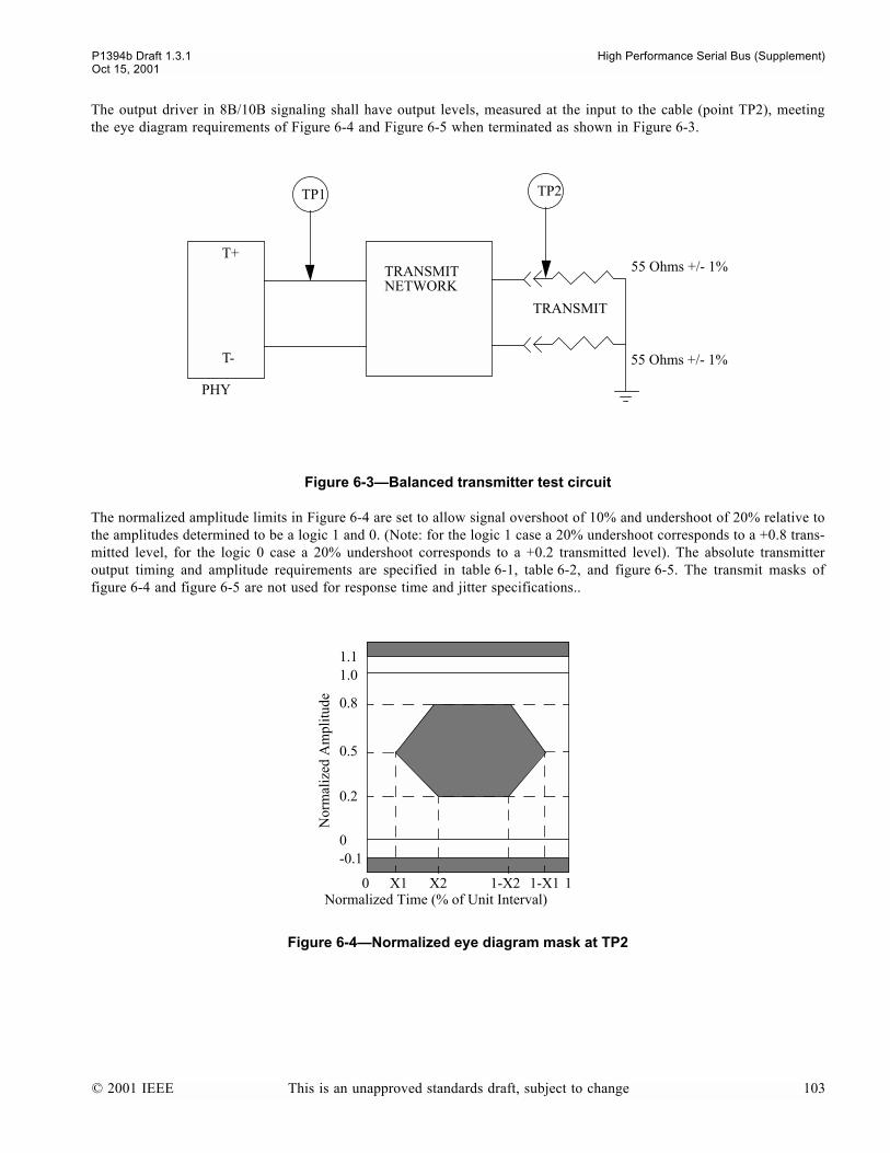
P1394b Draft 1.3.1 High Performance Serial Bus (Supplement)Oct 15, 2001
The output driver in 8B/10B signaling shall have output levels, measured at the input to the cable (point TP2), meetingthe eye diagram requirements of Figure 6-4 and Figure 6-5 when terminated as shown in Figure 6-3.
The normalized amplitude limits in Figure 6-4 are set to allow signal overshoot of 10% and undershoot of 20% relative tothe amplitudes determined to be a logic 1 and 0. (Note: for the logic 1 case a 20% undershoot corresponds to a +0.8 trans-mitted level, for the logic 0 case a 20% undershoot corresponds to a +0.2 transmitted level). The absolute transmitteroutput timing and amplitude requirements are specified in table 6-1, table 6-2, and figure 6-5. The transmit masks offigure 6-4 and figure 6-5 are not used for response time and jitter specifications..
Figure 6-3Balanced transmitter test circuit
Figure 6-4Normalized eye diagram mask at TP2
T+
T-
TRANSMITNETWORK
55 Ohms +/- 1%
55 Ohms +/- 1%
TRANSMIT
TP1 TP2
PHY
0 X1 X2 1-X2 1-X1 1
-0.10
0.2
0.5
0.8
1.01.1
Nor
mal
ized
Am
plitu
de
Normalized Time (% of Unit Interval)
© 2001 IEEE This is an unapproved standards draft, subject to change 103
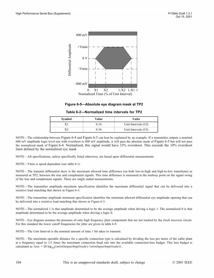
High Performance Serial Bus (Supplement) P1394b Draft 1.3.1Oct 15, 2001
NOTEThe relationship between Figure 6-4 and Figure 6-5 can best be explained by an example. If a transmitter outputs a nominal600 mV amplitude logic level one with overshoot to 800 mV amplitude, it will pass the absolute mask of Figure 6-5 but will not passthe normalized mask of Figure 6-4. Normalized, this signal would have 33% overshoot. This exceeds the 10% overshootlimit defined by the normalized eye mask
NOTEAll specifications, unless specifically listed otherwise, are based upon differential measurements
NOTEVmin is speed dependent (see table 6-1)
NOTEThe transmit differential skew is the maximum allowed time difference (on both low-to-high and high-to-low transitions) asmeasured at TP2, between the true and complement signals. This time difference is measured at the midway point on the signal swingof the true and complement signals. These are single ended measurements.
NOTEThe transmitter amplitude maximum specification identifies the maximum differential signal that can be delivered into aresistive load matching that shown in Figure 6-3.
NOTEThe transmitter amplitude minimum specification identifies the minimum allowed differential eye amplitude opening that canbe delivered into a resistive load matching that shown in Figure 6-3.
NOTEThe normalized 1 is that amplitude determined to be the average amplitude when driving a logic 1. The normalized 0 is thatamplitude determined to be the average amplitude when driving a logic 0.
NOTEEye diagram assumes the presence of only high frequency jitter components that are not tracked by the clock recovery circuit.For this standard the lower cutoff frequencies for jitter are given in table 6-9.
NOTEThe Unit Interval is the nominal amount of time 1 bit takes to transmit.
NOTEThe maximum operable distance for a specific connection type is calculated by dividing the loss per meter of the cable plantat a frequency equal to 1/2 times the maximum connection baud rate into the available connection-loss budget. This loss budget iscalculated as .
Figure 6-5Absolute eye diagram mask at TP2
Table 6-2Normalized time intervals for TP2
Symbol Value Units
X1 0.14 Unit Intervals (UI)
X2 0.34 Unit Intervals (UI)
0 X1 X2 1-X2 1-X1 1
-800 mV
-Vmin
0 V
+Vmin
800 mV
Dif
fere
ntia
l Am
plitu
de
Normalized Time (% of Unit Interval)
loss 20 minOutputAmplitude( ) minInputAmplitude( )Ú( )10log=
104 This is an unapproved standards draft, subject to change © 2001 IEEE

P1394b Draft 1.3.1 High Performance Serial Bus (Supplement)Oct 15, 2001
Transmitters shall be designed so as to not be damaged if a case occurs where, through a cabling error, two transmittersare directly connected.
6.3 Receiver electrical specifications
This standards receivers are part of bilingual or Beta-only ports. Receivers on bilingual ports when operating in Legacy(DS) mode shall operate as specified by the IEEE std 1394-1995 and IEEE std 1304a-2000, supporting all the standardelectrical operating modes. Additionally, bilingual and Beta-only receivers shall support a new electrical specification forgigabit signaling and at least S400 Beta mode signaling. In this higher speed mode of operation the input is assumed tohave new voltage levels, such as measured at TP3. For all connections, the receiver shall be DC-coupled for Data/Strobesignaling and may be AC-coupled for 8B/10B signaling through a receive network located between TP3 and TP4 asshown in Figure 6-2. The signal requirements for the receiver interface are listed in table 6-3. The receiver shall operatewithin the BER objective (10-12) when a short haul copper data connection is driven by a transmitter meeting the require-ments defined in table 6-1, table 6-2, figure 6-4 and figure 6-5, and a signal delivered to the receiver meeting the eye dia-gram requirements specified in figure 6-6
Figure 6-6Eye diagram mask at point-TP3
Table 6-3Short-haul copper receiver characteristics when using Beta mode
Parameter S400β S800β S1600β Units
Signaling 8B/10B 8B/10B 8B/10B N/A
Data rate 393.22 786.43 1,572.9 Mb/s
Nominal baud rate 491.52 983.04 1,966.1 MBd
Baud Rate Tolerance +/-100 +/-100 +/-100 ppm
Minimum differential sensitivity 200 200 200 mV
Input impedance test conditions:
TDR rise time 100 100 50 ps
Exception windowa 700 700 700 ps
Input impedance @ TP3:
Through connectionb 110 +/- 20 110 +/- 20 110 +/- 20 W
At terminationc 110 +/- 10 110 +/- 10 110 +/- 10 W
Differential skew 5% 5% 5% UI
0 0.3 0.7 1
-800mV
-200mV
0 V
200mV
800mV
Dif
fere
ntia
l Am
plitu
de
0.5Normalized Time
© 2001 IEEE This is an unapproved standards draft, subject to change 105
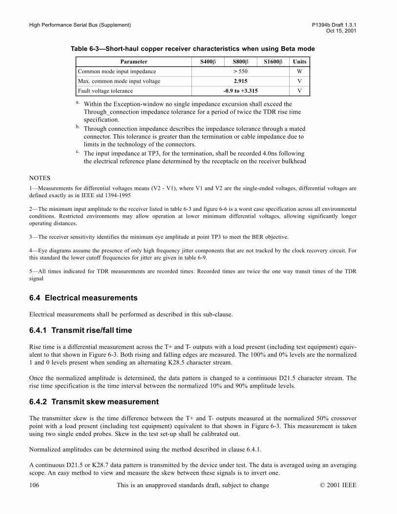
High Performance Serial Bus (Supplement) P1394b Draft 1.3.1Oct 15, 2001
NOTES
1Measurements for differential voltages means (V2 - V1), where V1 and V2 are the single-ended voltages, differential voltages aredefined exactly as in IEEE std 1394-1995
2The minimum input amplitude to the receiver listed in table 6-3 and figure 6-6 is a worst case specification across all environmentalconditions. Restricted environments may allow operation at lower minimum differential voltages, allowing significantly longeroperating distances.
3The receiver sensitivity identifies the minimum eye amplitude at point TP3 to meet the BER objective.
4Eye diagrams assume the presence of only high frequency jitter components that are not tracked by the clock recovery circuit. Forthis standard the lower cutoff frequencies for jitter are given in table 6-9.
5All times indicated for TDR measurements are recorded times. Recorded times are twice the one way transit times of the TDRsignal
6.4 Electrical measurements
Electrical measurements shall be performed as described in this sub-clause.
6.4.1 Transmit rise/fall time
Rise time is a differential measurement across the T+ and T- outputs with a load present (including test equipment) equiv-alent to that shown in Figure 6-3. Both rising and falling edges are measured. The 100% and 0% levels are the normalized1 and 0 levels present when sending an alternating K28.5 character stream.
Once the normalized amplitude is determined, the data pattern is changed to a continuous D21.5 character stream. Therise time specification is the time interval between the normalized 10% and 90% amplitude levels.
6.4.2 Transmit skew measurement
The transmitter skew is the time difference between the T+ and T- outputs measured at the normalized 50% crossoverpoint with a load present (including test equipment) equivalent to that shown in Figure 6-3. This measurement is takenusing two single ended probes. Skew in the test set-up shall be calibrated out.
Normalized amplitudes can be determined using the method described in clause 6.4.1.
A continuous D21.5 or K28.7 data pattern is transmitted by the device under test. The data is averaged using an averagingscope. An easy method to view and measure the skew between these signals is to invert one.
Common mode input impedance > 550 W
Max. common mode input voltage 2.915 V
Fault voltage tolerance -0.9 to +3.315 V
a. Within the Exception-window no single impedance excursion shall exceed the Through_connection impedance tolerance for a period of twice the TDR rise time specification.
b. Through connection impedance describes the impedance tolerance through a mated connector. This tolerance is greater than the termination or cable impedance due to limits in the technology of the connectors.
c. The input impedance at TP3, for the termination, shall be recorded 4.0ns following the electrical reference plane determined by the receptacle on the receiver bulkhead
Table 6-3Short-haul copper receiver characteristics when using Beta mode
Parameter S400β S800β S1600β Units
106 This is an unapproved standards draft, subject to change © 2001 IEEE

P1394b Draft 1.3.1 High Performance Serial Bus (Supplement)Oct 15, 2001
6.4.3 Transmit eye (normalized and absolute)
This test is made as a differential measurement at the bulkhead connector. The scope trigger shall either be a recoveredclock or a character clock internal to the equipment. The data pattern for this is the alternating K28.5, i.e., alternating thetwo different disparity K28.5 characters.
If a character trigger is used, the overshoot/undershoot percentages shall be measured at all ten bit positions. The load forthis test is that shown in Figure 6-3.
6.5 DC biasing
There are several ways in which Beta capable ports can be connected to other devices, e.g., Legacy ports, bilingual capa-ble ports, Beta mode only ports, and electro-optical networks.
Table 6-4 defines the bilingual port signals. For Legacy (DS) signaling, the transmitter on TPA generates TpBias. This isalso used to signal to a bilingual port that its connection partner is only Legacy capable. For a Beta mode port, TpBias isnot asserted. For this reason, Beta mode port is required to generate a bias for its own transmitter to enable signaling, e.g.,toning.
6.5.1 Beta mode receiver bias requirements
A Beta-only receiver is required to be AC coupled. A bilingual receiver is required to be DC coupled to the connectorpins. The transmitter on the other end of the connection may be AC or DC coupled to its connector pins. When thereceiver is AC coupled the receiver shall self-bias. When the receiver is DC coupled the receiver shall have a highcommon-mode input impedance (see table 6-3) and shall self-bias at this common-mode input impedance. The implica-tion of a high common-mode input impedance is that a DC coupled transmitter will set the receivers common mode inputbias voltage.
6.6 Toning and Signal Detect
This standards connectivity management requires the intermittent transmission of a tone and a signal detect function. Theparameters of the connection tone defined in this section are applicable to all physical media defined in this specification
Table 6-4Electrical signal assignments
Signal name Beta mode signal definition Data/Strobe signal definition
TPB* Differential Transmit Minus Strobe on receive, data on transmit (differential pair)
TPB Differential Transmit Plus
TPA* Differential Receive Minus Strobe on transmit, data on receive (differential pair)
TPA Differential Receive Plus
© 2001 IEEE This is an unapproved standards draft, subject to change 107
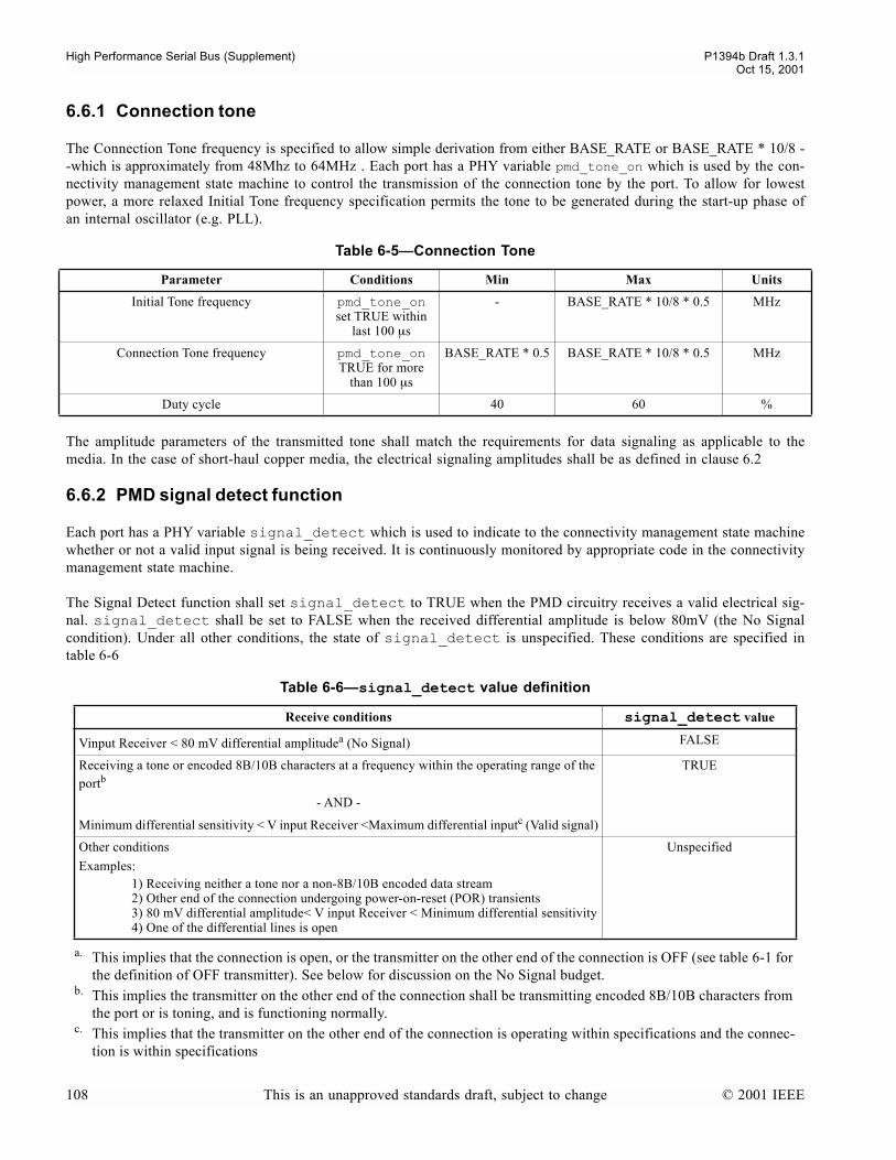
High Performance Serial Bus (Supplement) P1394b Draft 1.3.1Oct 15, 2001
6.6.1 Connection tone
The Connection Tone frequency is specified to allow simple derivation from either BASE_RATE or BASE_RATE * 10/8 --which is approximately from 48Mhz to 64MHz . Each port has a PHY variable pmd_tone_on which is used by the con-nectivity management state machine to control the transmission of the connection tone by the port. To allow for lowestpower, a more relaxed Initial Tone frequency specification permits the tone to be generated during the start-up phase ofan internal oscillator (e.g. PLL).
The amplitude parameters of the transmitted tone shall match the requirements for data signaling as applicable to themedia. In the case of short-haul copper media, the electrical signaling amplitudes shall be as defined in clause 6.2
6.6.2 PMD signal detect function
Each port has a PHY variable signal_detect which is used to indicate to the connectivity management state machinewhether or not a valid input signal is being received. It is continuously monitored by appropriate code in the connectivitymanagement state machine.
The Signal Detect function shall set signal_detect to TRUE when the PMD circuitry receives a valid electrical sig-nal. signal_detect shall be set to FALSE when the received differential amplitude is below 80mV (the No Signalcondition). Under all other conditions, the state of signal_detect is unspecified. These conditions are specified intable 6-6
Table 6-5Connection Tone
Parameter Conditions Min Max Units
Initial Tone frequency pmd_tone_on set TRUE within
last 100 µs
- BASE_RATE * 10/8 * 0.5 MHz
Connection Tone frequency pmd_tone_on TRUE for more
than 100 µs
BASE_RATE * 0.5 BASE_RATE * 10/8 * 0.5 MHz
Duty cycle 40 60 %
Table 6-6signal_detect value definition
Receive conditions signal_detect value
Vinput Receiver < 80 mV differential amplitudea (No Signal)
a. This implies that the connection is open, or the transmitter on the other end of the connection is OFF (see table 6-1 for the definition of OFF transmitter). See below for discussion on the No Signal budget.
FALSE
Receiving a tone or encoded 8B/10B characters at a frequency within the operating range of the portb
- AND -
Minimum differential sensitivity < V input Receiver <Maximum differential inputc (Valid signal)
b. This implies the transmitter on the other end of the connection shall be transmitting encoded 8B/10B characters from the port or is toning, and is functioning normally.
c. This implies that the transmitter on the other end of the connection is operating within specifications and the connec-tion is within specifications
TRUE
Other conditions
Examples:1) Receiving neither a tone nor a non-8B/10B encoded data stream2) Other end of the connection undergoing power-on-reset (POR) transients3) 80 mV differential amplitude< V input Receiver < Minimum differential sensitivity4) One of the differential lines is open
Unspecified
108 This is an unapproved standards draft, subject to change © 2001 IEEE
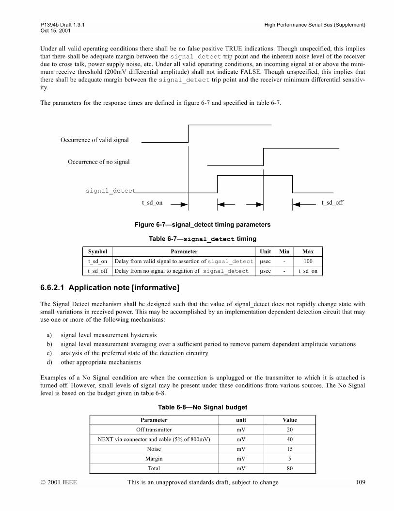
P1394b Draft 1.3.1 High Performance Serial Bus (Supplement)Oct 15, 2001
Under all valid operating conditions there shall be no false positive TRUE indications. Though unspecified, this impliesthat there shall be adequate margin between the signal_detect trip point and the inherent noise level of the receiverdue to cross talk, power supply noise, etc. Under all valid operating conditions, an incoming signal at or above the mini-mum receive threshold (200mV differential amplitude) shall not indicate FALSE. Though unspecified, this implies thatthere shall be adequate margin between the signal_detect trip point and the receiver minimum differential sensitiv-ity.
The parameters for the response times are defined in figure 6-7 and specified in table 6-7.
6.6.2.1 Application note [informative]
The Signal Detect mechanism shall be designed such that the value of signal_detect does not rapidly change state withsmall variations in received power. This may be accomplished by an implementation dependent detection circuit that mayuse one or more of the following mechanisms:
a) signal level measurement hysteresisb) signal level measurement averaging over a sufficient period to remove pattern dependent amplitude variationsc) analysis of the preferred state of the detection circuitryd) other appropriate mechanisms
Examples of a No Signal condition are when the connection is unplugged or the transmitter to which it is attached isturned off. However, small levels of signal may be present under these conditions from various sources. The No Signallevel is based on the budget given in table 6-8.
Figure 6-7signal_detect timing parameters
Table 6-7signal_detect timing
Symbol Parameter Unit Min Max
t_sd_on Delay from valid signal to assertion of signal_detect µsec - 100
t_sd_off Delay from no signal to negation of signal_detect µsec - t_sd_on
Table 6-8No Signal budget
Parameter unit Value
Off transmitter mV 20
NEXT via connector and cable (5% of 800mV) mV 40
Noise mV 15
Margin mV 5
Total mV 80
Occurrence of valid signal
signal_detect
t_sd_on t_sd_off
Occurrence of no signal
© 2001 IEEE This is an unapproved standards draft, subject to change 109
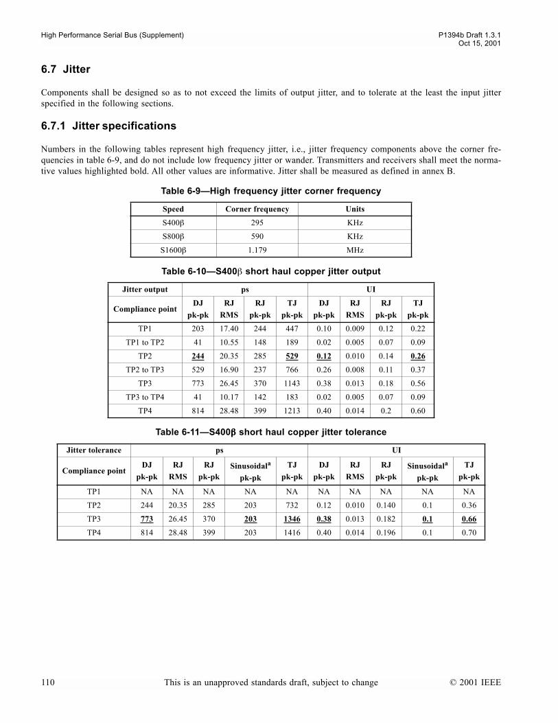
High Performance Serial Bus (Supplement) P1394b Draft 1.3.1Oct 15, 2001
6.7 Jitter
Components shall be designed so as to not exceed the limits of output jitter, and to tolerate at the least the input jitterspecified in the following sections.
6.7.1 Jitter specifications
Numbers in the following tables represent high frequency jitter, i.e., jitter frequency components above the corner fre-quencies in table 6-9, and do not include low frequency jitter or wander. Transmitters and receivers shall meet the norma-tive values highlighted bold. All other values are informative. Jitter shall be measured as defined in annex B.
Table 6-9High frequency jitter corner frequency
Speed Corner frequency Units
S400β 295 KHz
S800β 590 KHz
S1600β 1.179 MHz
Table 6-10S400β short haul copper jitter output
Jitter output ps UI
Compliance pointDJ
pk-pk
RJ
RMS
RJ
pk-pk
TJ
pk-pk
DJ
pk-pk
RJ
RMS
RJ
pk-pk
TJ
pk-pk
TP1 203 17.40 244 447 0.10 0.009 0.12 0.22
TP1 to TP2 41 10.55 148 189 0.02 0.005 0.07 0.09
TP2 244 20.35 285 529 0.12 0.010 0.14 0.26
TP2 to TP3 529 16.90 237 766 0.26 0.008 0.11 0.37
TP3 773 26.45 370 1143 0.38 0.013 0.18 0.56
TP3 to TP4 41 10.17 142 183 0.02 0.005 0.07 0.09
TP4 814 28.48 399 1213 0.40 0.014 0.2 0.60
Table 6-11S400ββββ short haul copper jitter tolerance
Jitter tolerance ps UI
Compliance pointDJ
pk-pk
RJ
RMS
RJ
pk-pkSinusoidala
pk-pk
TJ
pk-pk
DJ
pk-pk
RJ
RMS
RJ
pk-pkSinusoidala
pk-pk
TJ
pk-pk
TP1 NA NA NA NA NA NA NA NA NA NA
TP2 244 20.35 285 203 732 0.12 0.010 0.140 0.1 0.36
TP3 773 26.45 370 203 1346 0.38 0.013 0.182 0.1 0.66
TP4 814 28.48 399 203 1416 0.40 0.014 0.196 0.1 0.70
110 This is an unapproved standards draft, subject to change © 2001 IEEE
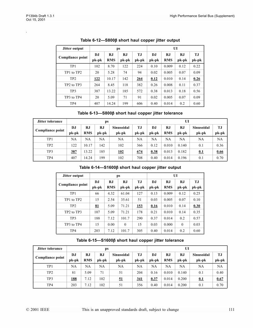
P1394b Draft 1.3.1 High Performance Serial Bus (Supplement)Oct 15, 2001
.
Table 6-12S800ββββ short haul copper jitter output
Jitter output ps UI
Compliance pointDJ
pk-pk
RJ
RMS
RJ
pk-pk
TJ
pk-pk
DJ
pk-pk
RJ
RMS
RJ
pk-pk
TJ
pk-pk
TP1 102 8.70 122 224 0.10 0.009 0.12 0.22
TP1 to TP2 20 5.28 74 94 0.02 0.005 0.07 0.09
TP2 122 10.17 142 264 0.12 0.010 0.14 0.26
TP2 to TP3 264 8.45 118 382 0.26 0.008 0.11 0.37
TP3 387 13.22 185 572 0.38 0.013 0.18 0.56
TP3 to TP4 20 5.09 71 91 0.02 0.005 0.07 0.09
TP4 407 14.24 199 606 0.40 0.014 0.2 0.60
Table 6-13S800ββββ short haul copper jitter tolerance
Jitter tolerance ps UI
Compliance pointDJ
pk-pk
RJ
RMS
RJ
pk-pk
Sinusoidal
pk-pk
TJ
pk-pk
DJ
pk-pk
RJ
RMS
RJ
pk-pk
Sinusoidal
pk-pk
TJ
pk-pk
TP1 NA NA NA NA NA NA NA NA NA NA
TP2 122 10.17 142 102 366 0.12 0.010 0.140 0.1 0.36
TP3 387 13.22 185 102 674 0.38 0.013 0.182 0.1 0.66
TP4 407 14.24 199 102 708 0.40 0.014 0.196 0.1 0.70
Table 6-14S1600ββββ short haul copper jitter output
Jitter output ps UI
Compliance pointDJ
pk-pk
RJ
RMS
RJ
pk-pk
TJ
pk-pk
DJ
pk-pk
RJ
RMS
RJ
pk-pk
TJ
pk-pk
TP1 66 4.32 61.04 127 0.13 0.009 0.12 0.25
TP1 to TP2 15 2.54 35.61 51 0.03 0.005 0.07 0.10
TP2 81 5.09 71.21 153 0.16 0.010 0.14 0.30
TP2 to TP3 107 5.09 71.21 178 0.21 0.010 0.14 0.35
TP3 188 7.12 101.7 290 0.37 0.014 0.2 0.57
TP3 to TP4 15 0.00 0 15 0.03 0.000 0 0.03
TP4 203 7.12 101.7 305 0.40 0.014 0.2 0.60
Table 6-15S1600ββββ short haul copper jitter tolerance
Jitter tolerance ps UI
Compliance pointDJ
pk-pk
RJ
RMS
RJ
pk-pk
Sinusoidal
pk-pk
TJ
pk-pk
DJ
pk-pk
RJ
RMS
RJ
pk-pk
Sinusoidal
pk-pk
TJ
pk-pk
TP1 NA NA NA NA NA NA NA NA NA NA
TP2 81 5.09 71 51 204 0.16 0.010 0.140 0.1 0.40
TP3 188 7.12 102 51 341 0.37 0.014 0.200 0.1 0.67
TP4 203 7.12 102 51 356 0.40 0.014 0.200 0.1 0.70
© 2001 IEEE This is an unapproved standards draft, subject to change 111

High Performance Serial Bus (Supplement) P1394b Draft 1.3.1Oct 15, 2001
112 This is an unapproved standards draft, subject to change © 2001 IEEE

P1394b Draft 1.3.1 High Performance Serial Bus (Supplement)Oct 15, 2001
7. Glass optical fiber physical medium dependent specification
This section specifies the optical signaling properties for an alternate physical layer. The focus is on short wavelengthlasers (VCSELs) and glass fibers for long haul distances. This is a specification for a low cost fiber optical interconnect.Current specifications cover S400β, S800β and S1600β optical connections.
Figure 7-1 shows the relationship of this clause to the PHY master architecture.
Figure 7-1PHY master architecture (Glass optical fiber PMD in context)
BOSS arbitration and control state machines.
Link
B PHY
PHY-Link interface
packet transmit/receive
port controller
DS mode functions
Beta mode
functions
Connection management
Low power signaling
Port
to other ports
pa
cke
t d
ata
send LTP PHY packets
req
ue
st\
gra
nt
packet control
LTP RX flags
TX/RX symbol,port status
TX/RX symbol
TX/RX symbol,enables
con
tro
l
con
figco
ntr
ol
po
rtst
atu
s
Glass optical fiber
PMD
DS mode functions
Beta mode
functions
Connection management
Low power signaling
Port
PHY packets
TX/RX data signals, PMD control/status,arb/connect control/status (DS only)
TX/RX data signals, PMD control/status,arb/connect control/status (DS only)
Glass optical fiber
PMD
request/grant, enable
© 2001 IEEE This is an unapproved standards draft, subject to change 113

High Performance Serial Bus (Supplement) P1394b Draft 1.3.1Oct 15, 2001
7.1 PMD block diagram
For purposes of system conformance, the PMD sublayer is standardized at the following points. The optical transmitsignal is defined at the output end of a 5 meter or less patch cord (TP2) of a type consistent with the connection type con-nected to the transmitter receptacle defined in clause 7.10.1. The optical receive signal is defined at the output of the cableplant (TP3) connected to the receiver receptacle defined in clause 7.10.1.
TP1 and TP4 are standardized reference points for use by implementers to certify component conformance. The electricalspecifications of the PMD service interface (TP1 and TP4) are not system compliance points (these are not readily test-able in a system implementation).
7.2 PMD to MDI optical specifications
The operating range is defined in Table 7-1. A compliant transceiver is capable of supporting the multimode fiber mediatype listed in Table 7-1 (i.e. 50 µm multimode fiber) according to the specifications defined in this clause. A transceiverwhich exceeds the operational range requirement while meeting all other optical specifications is considered compliant.
Figure 7-2PMD block diagram
Table 7-1Operating range for 50 µµµµm MMF
Signaling speed Range (meters)
S400β 2 to 100
S800β 2 to 100
S1600β 2 to 100
T+
T-
R+
R-
Optical Fiber Media
TP1 TP4TP3TP2
Optical
PMD
Transmitter
Optical
PMD
Receiver
System Bulkheads
Signal_Detect(Optional)
PatchCord
MDI MDI
114 This is an unapproved standards draft, subject to change © 2001 IEEE

P1394b Draft 1.3.1 High Performance Serial Bus (Supplement)Oct 15, 2001
7.3 Transmitter optical specifications
The optical transmitter shall meet the specifications defined in Table 7-2 per measurement techniques defined inclause 7.7. It shall also meet a transmit mask of the eye measurement as defined in clause 7.7.5.
7.4 Receiver optical specifications
The optical receiver shall meet the specifications defined in Table 7-3 per measurement techniques defined in clause 7.7.
Table 7-2Optical transmit characteristics
Description 50 µµµµm MMF value Unit
Transmitter type Shortwave Laser
Signaling rate S400βS800β
S1600β
Wavelength (λ, range) 830 to 860 nm
Trise/Tfall (max; 20%-80%) 0.26 ns
RMS spectral width (max) 2 nm
Average launch power (max) See footnotea
a. The launch power shall be the lesser of the class 1 safety limit or the maximum receive power defined by Table 7-3.
dBm
Average launch power (min) -10 dBm
Average launch power of OFF transmitter (max)b
b. Examples of an OFF transmitter are: no power supplied to the PMD, laser shut-down for safety conditions, activation of a transmit disable or other optional module laser shut down conditions. During all conditions when the optical port is powered the AC signal (data) into the transmit port will be valid encoded 8B/10B patterns except for short durations during system power-on-reset or diagnostics when the optical port is placed in a loopback mode.
-35 dBm
Extinction ratio (min) 7 dB
RIN (max) -117 dB/Hz
Coupled power ratio (CPR)c d
c. Radial overfilled launches, as described in clause 7.11.1, while they may meet CPR ranges, should be avoided.
d. The CPR provides sufficient mode volume so individual multimode fiber (MMF) modes do not dominate fiber performance. This reduces the effect of peak-to-peak differential mode delay (DMD) between the launched mode groups and diminishes the pulse splitting nulls in the frequency response
9 < CPR dB
Table 7-3Optical receive characteristics
Description Value Unit
Signaling rate S400βS800β
S1600β
Wavelength (range) 830 to 860 nm
Average receive power (max) 0 dBm
Receive sensitivity (min) -16.5 dBm
Return loss (min) 12 dB
© 2001 IEEE This is an unapproved standards draft, subject to change 115
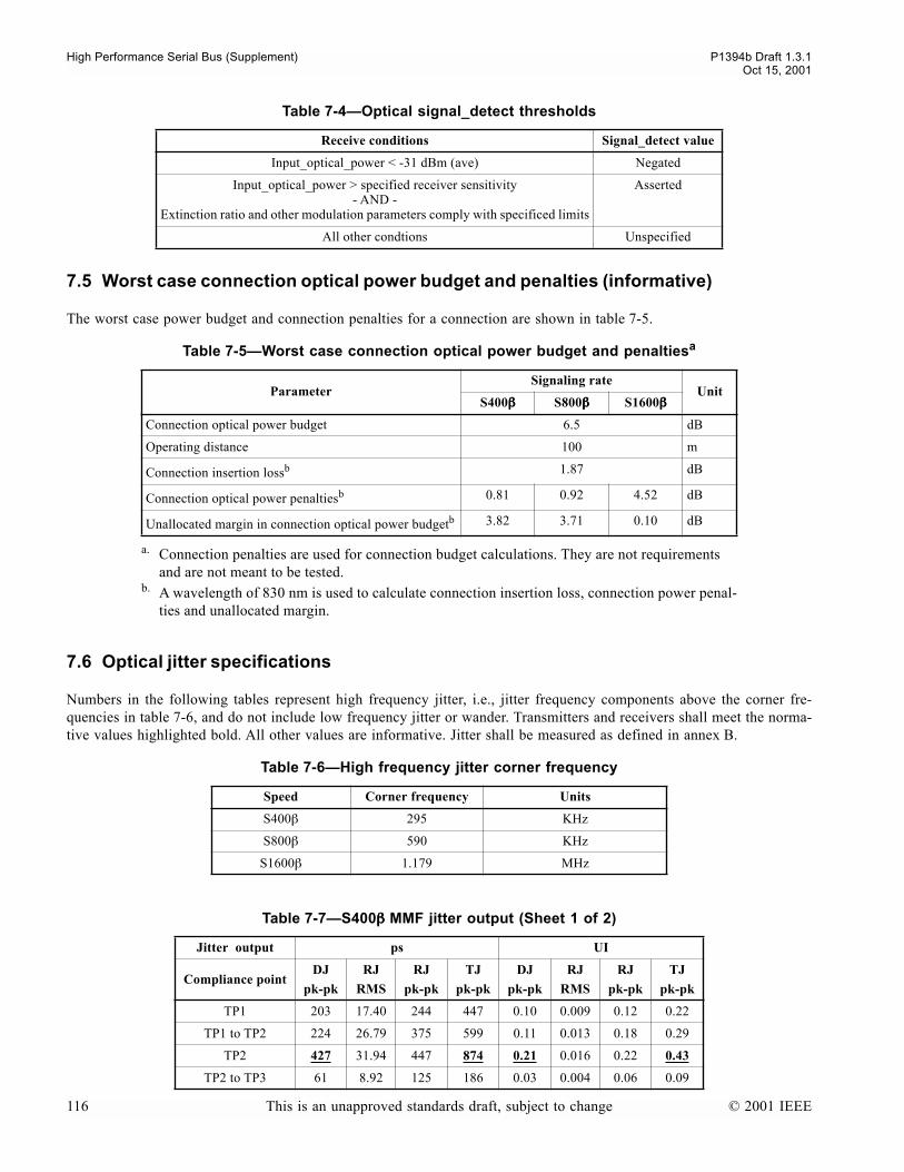
High Performance Serial Bus (Supplement) P1394b Draft 1.3.1Oct 15, 2001
7.5 Worst case connection optical power budget and penalties (informative)
The worst case power budget and connection penalties for a connection are shown in table 7-5.
7.6 Optical jitter specifications
Numbers in the following tables represent high frequency jitter, i.e., jitter frequency components above the corner fre-quencies in table 7-6, and do not include low frequency jitter or wander. Transmitters and receivers shall meet the norma-tive values highlighted bold. All other values are informative. Jitter shall be measured as defined in annex B.
Table 7-4Optical signal_detect thresholds
Receive conditions Signal_detect value
Input_optical_power < -31 dBm (ave) Negated
Input_optical_power > specified receiver sensitivity- AND -
Extinction ratio and other modulation parameters comply with specificed limits
Asserted
All other condtions Unspecified
Table 7-5Worst case connection optical power budget and penaltiesa
a. Connection penalties are used for connection budget calculations. They are not requirements and are not meant to be tested.
ParameterSignaling rate
UnitS400ββββ S800ββββ S1600ββββ
Connection optical power budget 6.5 dB
Operating distance 100 m
Connection insertion lossb
b. A wavelength of 830 nm is used to calculate connection insertion loss, connection power penal-ties and unallocated margin.
1.87 dB
Connection optical power penaltiesb 0.81 0.92 4.52 dB
Unallocated margin in connection optical power budgetb 3.82 3.71 0.10 dB
Table 7-6High frequency jitter corner frequency
Speed Corner frequency Units
S400β 295 KHz
S800β 590 KHz
S1600β 1.179 MHz
Table 7-7S400ββββ MMF jitter output (Sheet 1 of 2)
Jitter output ps UI
Compliance pointDJ
pk-pk
RJ
RMS
RJ
pk-pk
TJ
pk-pk
DJ
pk-pk
RJ
RMS
RJ
pk-pk
TJ
pk-pk
TP1 203 17.40 244 447 0.10 0.009 0.12 0.22
TP1 to TP2 224 26.79 375 599 0.11 0.013 0.18 0.29
TP2 427 31.94 447 874 0.21 0.016 0.22 0.43
TP2 to TP3 61 8.92 125 186 0.03 0.004 0.06 0.09
116 This is an unapproved standards draft, subject to change © 2001 IEEE

P1394b Draft 1.3.1 High Performance Serial Bus (Supplement)Oct 15, 2001
TP3 488 33.16 464 952 0.24 0.016 0.23 0.47
TP3 to TP4 346 10.17 142 488 0.17 0.005 0.07 0.24
TP4 834 34.59 484 1318 0.41 0.017 0.24 0.65
Table 7-8S400ββββ MMF jitter tolerance
Jitter tolerance ps UI
Compliance pointDJ
pk-pk
RJ
RMS
RJ
pk-pk
Sinusoidal
pk-pk
TJ
pk-pk
DJ
pk-pk
RJ
RMS
RJ
pk-pk
Sinusoidal
pk-pk
TJ
pk-pk
TP1 NA NA NA NA NA NA NA NA NA NA
TP2 427 31.94 447 203 975 0.21 0.016 0.220 0.1 0.48
TP3 488 33.16 464 203 1053 0.24 0.016 0.228 0.1 0.52
TP4 834 34.59 484 203 1419 0.41 0.017 0.238 0.1 0.70
Table 7-9S800ββββ MMF jitter output
Jitter output ps UI
Compliance pointDJ
pk-pk
RJ
RMS
RJ
pk-pk
TJ
pk-pk
DJ
pk-pk
RJ
RMS
RJ
pk-pk
TJ
pk-pk
TP1 102 8.70 122 224 0.10 0.009 0.12 0.22
TP1 to TP2 112 13.40 118 300 0.11 0.013 0.18 0.29
TP2 214 15.97 224 438 0.21 0.016 0.22 0.43
TP2 to TP3 31 4.46 62 93 0.03 0.004 0.06 0.09
TP3 244 16.58 232 476 0.24 0.016 0.23 0.47
TP3 to TP4 173 5.09 71 244 0.17 0.005 0.07 0.24
TP4 417 17.29 242 659 0.41 0.017 0.24 0.65
Table 7-10S800ββββ MMF jitter tolerance
Jitter tolerance ps UI
Compliance pointDJ
pk-pk
RJ
RMS
RJ
pk-pkSinusoidala
pk-pk
a. The applied sinusoidal shall be swept at a frequency of 637 KHz
TJ
pk-pk
DJ
pk-pk
RJ
RMS
RJ
pk-pkSinusoidala
pk-pk
TJ
pk-pk
TP1 NA NA NA NA NA NA NA NA NA NA
TP2 214 15.97 224 102 489 0.21 0.016 0.220 0.1 0.48
TP3 244 16.58 232 102 527 0.24 0.016 0.228 0.1 0.52
TP4 417 17.29 242 102 710 0.41 0.017 0.238 0.1 0.70
Table 7-7S400ββββ MMF jitter output (Sheet 2 of 2)
Jitter output ps UI
Compliance pointDJ
pk-pk
RJ
RMS
RJ
pk-pk
TJ
pk-pk
DJ
pk-pk
RJ
RMS
RJ
pk-pk
TJ
pk-pk
© 2001 IEEE This is an unapproved standards draft, subject to change 117

High Performance Serial Bus (Supplement) P1394b Draft 1.3.1Oct 15, 2001
7.7 Optical measurement requirements
All optical measurements shall be made through a short patch cable, between 2 and 5 meters in length.
7.7.1 Center wavelength and spectral width measurements
The center wavelength and spectral width (RMS) shall be measured using an optical spectrum analyzer per TIA/EIA-455-127. Spectral width shall be measured under modulated conditions using a valid encoded 8B/10B pattern under full powerconditions across nominal operating temperatures.
7.7.2 Optical power measurements
Optical power shall be measured using the methods specified in TIA/EIA-455-95. This measurement may be made withthe node transmitting any valid 8B/10B data stream.
7.7.3 Extinction ratio measurements
Extinction ratio shall be measured using the methods specified in TIA/EIA-526-4A. This measurement may be made withthe node transmitting a repeating K28.7 data pattern. The extinction ratio is measured under fully modulated conditionswith worst case reflections.
NOTEK28.7 generates a 50, 100 or 200 MHz square wave, depending on whether connection is operating at S400β, S800 or S1600,respectively.
Table 7-11S1600ββββ MMF jitter output
Jitter output ps UI
Compliance pointDJ
pk-pk
RJ
RMS
RJ
pk-pk
TJ
pk-pk
DJ
pk-pk
RJ
RMS
RJ
pk-pk
TJ
pk-pk
TP1 66 4.32 61 127 0.13 0.009 0.12 0.25
TP1 to TP2 66 5.09 71 137 0.13 0.010 0.14 0.27
TP2 132 6.68 92 224 0.26 0.013 0.18 0.44
TP2 to TP3 15 1.53 20 36 0.03 0.003 0.04 0.07
TP3 148 6.87 97 244 0.29 0.014 0.19 0.48
TP3 to TP4 56 6.10 86 142 0.11 0.012 0.17 0.28
TP4 203 9.16 127 331 0.40 0.018 0.25 0.65
Table 7-12S1600ββββ MMF jitter tolerance
Jitter tolerance ps UI
Compliance pointDJ
pk-pk
RJ
RMS
RJ
pk-pkSinusoidala
pk-pk
a. The applied sinusoidal shall be swept at a frequency of 1275 KHz
TJ
pk-pk
DJ
pk-pk
RJ
RMS
RJ
pk-pkSinusoidala
pk-pk
TJ
pk-pk
TP1 NA NA NA NA NA NA NA NA NA NA
TP2 132 6.68 92 51 249 0.26 0.013 0.180 0.1 0.49
TP3 148 6.87 97 51 270 0.29 0.014 0.190 0.1 0.53
TP4 203 9.16 127 51 356 0.40 0.018 0.250 0.1 0.70
118 This is an unapproved standards draft, subject to change © 2001 IEEE

P1394b Draft 1.3.1 High Performance Serial Bus (Supplement)Oct 15, 2001
7.7.4 Relative Intensity Noise (RIN).
RIN shall be measured according to ANSI X3.230-1994 FC-PH Appendix A, subclause A.5, Relative intensity noise(RIN) measuring procedure. Per this FC-PH appendix, this procedure describes a component test which may not beappropriate for a system level test depending on the implementation.
7.7.5 Transmitter optical waveform (transmit eye)
The required transmitter pulse shape characteristics are specified in the form of a mask of the transmitter eye diagram asshown in figure 7-3. The transmit mask is not used for response time and jitter specification.
Normalized amplitudes of 0.0 and 1.0 represent the amplitudes of logic ZERO and ONE respectively.
The eye shall be measured with respect to the mask of the eye using a fourth-order Bessel Thompson filter with a transferfunction given by:
where:
and where the filter response versus frequency range for this fourth order Bessel Thompson filter is defined in ITU-TG.957, along with the allowed tolerances for its physical implementation.
NOTES
1This Bessel Thompson filter is not intended to represent the noise filter used within an optical receiver, but is intended to provideuniform measurement conditions at the transmitter.
2The fourth order Bessel-Thompson filter is reactive. In order to suppress reflections, a 6 dB attenuator may be required at the filteroutput.
Figure 7-3Transmitter eye mask definition
0
-20
20
50
80
100
130
Nor
mal
ized
Am
plitu
de (
%)
Normalized Time (% of Unit Interval)
0 1.0Normalized Time (Unit Interval)
0 22 37.5 62.5 78 100
Nor
mal
ized
Am
plitu
de
0.0
-0.20
0.20
0.50
0.80
1.00
1.30
0.22 0.375 0.625 0.78
Hp105
105 105y 45y2
10y3
y4
+ + + +---------------------------------------------------------------------------=
y 2.114 p ; pjωωr------ ; ωr 2π f r ; f r= 1.500GHz= = =
© 2001 IEEE This is an unapproved standards draft, subject to change 119
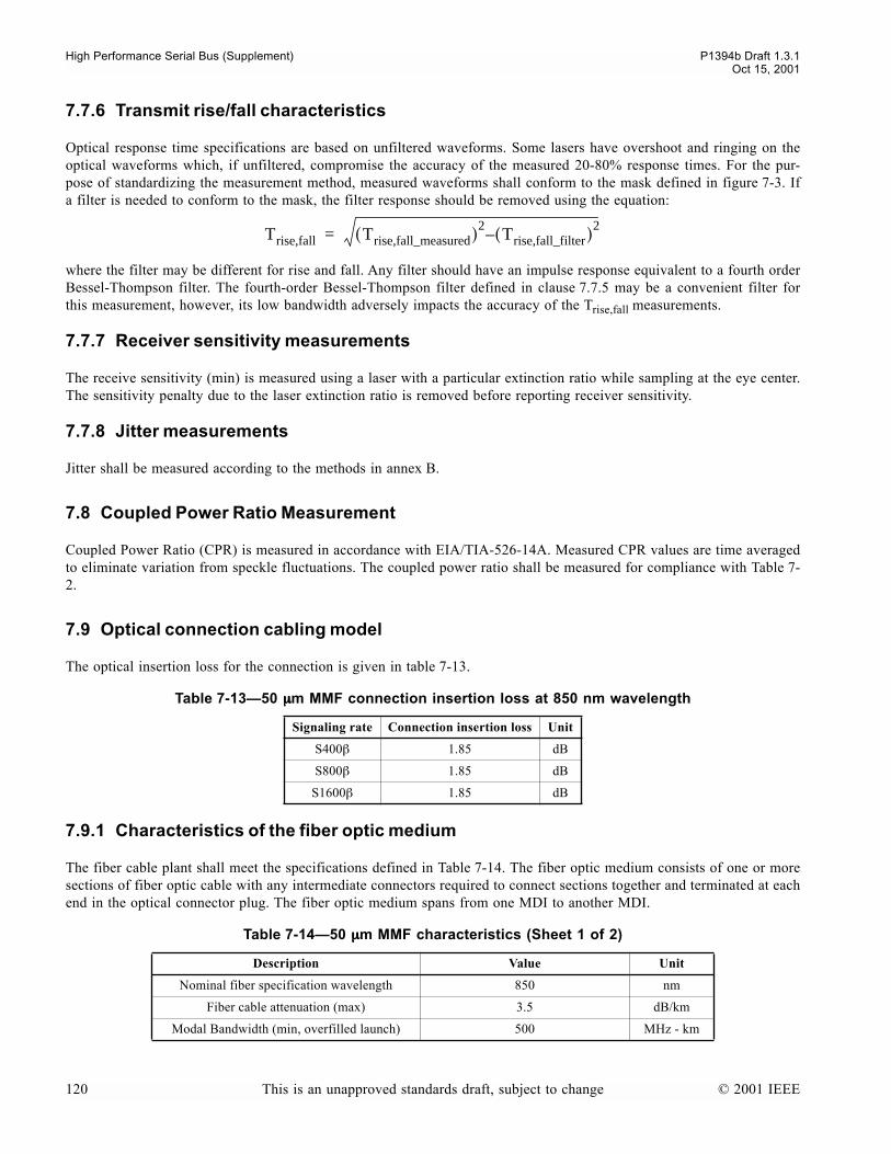
High Performance Serial Bus (Supplement) P1394b Draft 1.3.1Oct 15, 2001
7.7.6 Transmit rise/fall characteristics
Optical response time specifications are based on unfiltered waveforms. Some lasers have overshoot and ringing on theoptical waveforms which, if unfiltered, compromise the accuracy of the measured 20-80% response times. For the pur-pose of standardizing the measurement method, measured waveforms shall conform to the mask defined in figure 7-3. Ifa filter is needed to conform to the mask, the filter response should be removed using the equation:
where the filter may be different for rise and fall. Any filter should have an impulse response equivalent to a fourth orderBessel-Thompson filter. The fourth-order Bessel-Thompson filter defined in clause 7.7.5 may be a convenient filter forthis measurement, however, its low bandwidth adversely impacts the accuracy of the Trise,fall measurements.
7.7.7 Receiver sensitivity measurements
The receive sensitivity (min) is measured using a laser with a particular extinction ratio while sampling at the eye center.The sensitivity penalty due to the laser extinction ratio is removed before reporting receiver sensitivity.
7.7.8 Jitter measurements
Jitter shall be measured according to the methods in annex B.
7.8 Coupled Power Ratio Measurement
Coupled Power Ratio (CPR) is measured in accordance with EIA/TIA-526-14A. Measured CPR values are time averagedto eliminate variation from speckle fluctuations. The coupled power ratio shall be measured for compliance with Table 7-2.
7.9 Optical connection cabling model
The optical insertion loss for the connection is given in table 7-13.
7.9.1 Characteristics of the fiber optic medium
The fiber cable plant shall meet the specifications defined in Table 7-14. The fiber optic medium consists of one or moresections of fiber optic cable with any intermediate connectors required to connect sections together and terminated at eachend in the optical connector plug. The fiber optic medium spans from one MDI to another MDI.
Table 7-1350 µµµµm MMF connection insertion loss at 850 nm wavelength
Signaling rate Connection insertion loss Unit
S400β 1.85 dB
S800β 1.85 dB
S1600β 1.85 dB
Table 7-1450 µµµµm MMF characteristics (Sheet 1 of 2)
Description Value Unit
Nominal fiber specification wavelength 850 nm
Fiber cable attenuation (max) 3.5 dB/km
Modal Bandwidth (min, overfilled launch) 500 MHz - km
Trise,fall Trise,fall_measured( )2Trise,fall_filter( )–
2=
120 This is an unapproved standards draft, subject to change © 2001 IEEE

P1394b Draft 1.3.1 High Performance Serial Bus (Supplement)Oct 15, 2001
7.9.2 Optical fiber and cable
The optical medium requirements are satisfied by the fiber specified in IEC 793-2:1992. Type A1a (50/125 µm multi-mode).
7.9.3 Multimode connector insertion loss
The maximum connection distances for multimode fiber are calculated based on an allocation of 1.5 dB total connectionloss. This allocation supports a minimum of three connections with an average insertion loss equal to 0.5 dB (or less) perconnection, or two connections (as shown in figure 7-4) with a maximum insertion loss of 0.75 dB.
7.9.4 Optical connection return loss
The return loss for multimode connections shall be greater than 20 dB.
7.10 Optical connection
The optical connection (plug and receptacle) shall be the duplex LC, meeting the following requirements:
a) performance complies to TIA-568b) meet the dimension and interface specifications of the FOCIS 10 addendum of the TIA/EIA 604, Fiber Optic
Connector Intermateability Standards.c) ensure that polarity is maintained
Zero dispersion wavelength (l0) 1295 ≤ l0 ≤ 1320 nm
Dispersion slope (max) (S0) 0.11 for 1300 ≤ l0 ≤ 1320
and 0.001(l0 -1190) for
1295 ≤ l0 ≤ 1300
ps/nm2 - km
Figure 7-4Optical Fiber Cabling model
Table 7-1450 µµµµm MMF characteristics (Sheet 2 of 2)
Description Value Unit
PMDConnectionConnectionPMD
Optical Fiber Cabling (connection)
JumperCable
JumperCableBuilding Cable
MDI MDI
© 2001 IEEE This is an unapproved standards draft, subject to change 121
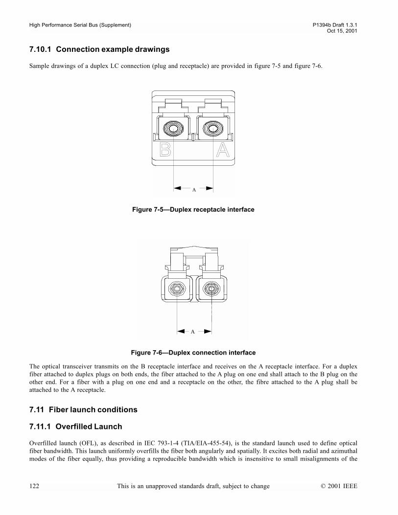
High Performance Serial Bus (Supplement) P1394b Draft 1.3.1Oct 15, 2001
7.10.1 Connection example drawings
Sample drawings of a duplex LC connection (plug and receptacle) are provided in figure 7-5 and figure 7-6.
The optical transceiver transmits on the B receptacle interface and receives on the A receptacle interface. For a duplexfiber attached to duplex plugs on both ends, the fiber attached to the A plug on one end shall attach to the B plug on theother end. For a fiber with a plug on one end and a receptacle on the other, the fibre attached to the A plug shall beattached to the A receptacle.
7.11 Fiber launch conditions
7.11.1 Overfilled Launch
Overfilled launch (OFL), as described in IEC 793-1-4 (TIA/EIA-455-54), is the standard launch used to define opticalfiber bandwidth. This launch uniformly overfills the fiber both angularly and spatially. It excites both radial and azimuthalmodes of the fiber equally, thus providing a reproducible bandwidth which is insensitive to small misalignments of the
Figure 7-5Duplex receptacle interface
Figure 7-6Duplex connection interface
A
B A
A
122 This is an unapproved standards draft, subject to change © 2001 IEEE

P1394b Draft 1.3.1 High Performance Serial Bus (Supplement)Oct 15, 2001
input fiber. It is also relatively insensitive to microbending and macrobending when they are not sufficient to affect powerdistribution carried by the fiber. A restricted launch gives a less reproducible bandwidth number and is dependent on anexact definition of the launch.
© 2001 IEEE This is an unapproved standards draft, subject to change 123

High Performance Serial Bus (Supplement) P1394b Draft 1.3.1Oct 15, 2001
124 This is an unapproved standards draft, subject to change © 2001 IEEE
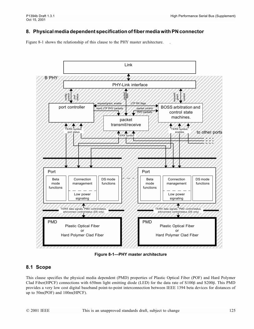
P1394b Draft 1.3.1 High Performance Serial Bus (Supplement)Oct 15, 2001
8. Physical media dependent specification of fiber media with PN connector
Figure 8-1 shows the relationship of this clause to the PHY master architecture.
8.1 Scope
This clause specifies the physical media dependent (PMD) properties of Plastic Optical Fiber (POF) and Hard PolymerClad Fiber(HPCF) connections with 650nm light emitting diode (LED) for the data rate of S100β and S200β. This PMDprovides a very low cost digital baseband point-to-point interconnection between IEEE 1394 beta devices for distances ofup to 50m(POF) and 100m(HPCF).
Figure 8-1PHY master architecture
BOSS arbitration and control state machines.
Plastic Optical Fiberor
Hard Polymer Clad Fiber
Link
B PHY
PHY-Link interface
packet transmit/receive
port controller
DS mode functions
Beta mode
functions
Connection management
Low power signaling
Port
to other ports
pa
cke
t d
ata
send LTP PHY packets
req
ue
st\
gra
nt
packet control
request/grant, enable LTP RX flags
TX/RX symbol,port status
TX/RX symbol
TX/RX symbol,enables
con
tro
l
con
figco
ntr
ol
po
rtst
atu
s
PMDPlastic Optical Fiber
orHard Polymer Clad Fiber
PMD
DS mode functions
Beta mode
functions
Connection management
Low power signaling
Port
PHY packets
TX/RX data signals, PMD control/status,arb/connect control/status (DS only)
TX/RX data signals, PMD control/status,arb/connect control/status (DS only)
.
© 2001 IEEE This is an unapproved standards draft, subject to change 125

High Performance Serial Bus (Supplement) P1394b Draft 1.3.1Oct 15, 2001
The PMD specified in this clause has the following general characteristics:
- Provides a means of converting the IEEE 1394 beta physical layer to the POF and HPCFconnection segment.- Provides a means of transmitting and receiving the optical signal between two optical interfaces.- Provides S100β / S200β dual mode capability for interconnecting S200β interface to S100β interface over common
optical cable and connectors during a startup mode.
8.2 PMD block diagram
For purposes of system conformance, the PMD sublayer is standardized at the following points. The optical transmitsignal is defined at the output end of a 5 meter or less patch cord (TP2) of a type consistent with the connection type con-nected to the transmitter receptacle defined in clause 8.4. The optical receive signal is defined at the output of the cableplant (TP3) connected to the receiver receptacle defined in clause 8.4.
TP1 and TP4 are standardized reference points for use by implementers to certify component conformance. The electricalspecifications of the PMD service interface (TP1 and TP4) are not system compliance points (these are not readily test-able in a system implementation).
8.3 Cables
The POF shall be 1000 µm step index multimode plastic optical fiber. The HPCF shall be 225 µm graded index multi-mode hard polymer clad fiber. POF shall have a minimum modal bandwidth of 10 MHz*km at 650 nm when measured inaccordance with IEC 793-1-C2A or IEC 793-1-C2B. HPCF shall have a minimum modal bandwidth of 25MHz*km at650 nm when measured in accordance with IEC 793-1-C2A or IEC 793-1-C2B. The specifications for fiber modal band-width include a variation in source numerical aperture and account for the effect of bandwidth degradation to ensure cor-rect system operation. The maximum attenuation of 50 m POF under the condition of -20 to +70 °C and 95% relativehumidity shall be 9.1 dB. The maximum attenuation of 100 m HPCF under the condition of -20 to +70 °C and 95% rela-tive humidity shall be 2.6 dB. The attenuation shall be measured in accordance with IEC 793-1-C1A or C1B using a nom-inal 650 nm narrow (< 5 nm FWHM) spectral width light source.
Figure 8-2PMD block diagram
T+
T-
R+
R-
Optical Fiber Media
TP1 TP4TP3TP2
Optical
PMD
Transmitter
Optical
PMD
Receiver
System Bulkheads
Signal_Detect(Optional)
PatchCord
MDI MDI
126 This is an unapproved standards draft, subject to change © 2001 IEEE
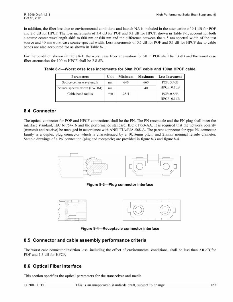
P1394b Draft 1.3.1 High Performance Serial Bus (Supplement)Oct 15, 2001
In addition, the fiber loss due to environmental conditions and launch NA is included in the attenuation of 9.1 dB for POFand 2.6 dB for HPCF. The loss increments of 3.4 dB for POF and 0.1 dB for HPCF, shown in Table 8-1, account for botha source center wavelength shift to 660 nm or 640 nm and the difference between the < 5 nm spectral width of the testsource and 40 nm worst case source spectral width. Loss increments of 0.5 dB for POF and 0.1 dB for HPCF due to cablebends are also accounted for as shown in Table 8-1.
For the condition shown in Table 8-1, the worst case fiber attenuation for 50 m POF shall be 13 dB and the worst casefiber attenuation for 100 m HPCF shall be 2.8 dB.
8.4 Connector
The optical connector for POF and HPCF connections shall be the PN. The PN receptacle and the PN plug shall meet theinterface standard, IEC 61754-16 and the performance standard, IEC 61753-AA. It is required that the network polarity(transmit and receive) be managed in accordance with ANSI/TIA/EIA-568-A. The parent connector for type PN connectorfamily is a duplex plug connector which is characterized by a 10.16mm pitch, and 2.5mm nominal ferrule diameter.Sample drawings of a PN connection (plug and receptacle) are provided in figure 8-3 and figure 8-4.
8.5 Connector and cable assembly performance criteria
The worst case connector insertion loss, including the effect of environmental conditions, shall be less than 2.0 dB forPOF and 1.3 dB for HPCF.
8.6 Optical Fiber Interface
This section specifies the optical parameters for the transceiver and media.
Table 8-1Worst case loss increments for 50m POF cable and 100m HPCF cable
Parameters Unit Minimum Maximum Loss Increment
Source center wavelength nm 640 660 POF: 3.4dB
HPCF: 0.1dBSource spectral width (FWHM) nm 40
Cable bend radius mm 25.4 POF: 0.5dB
HPCF: 0.1dB
Figure 8-3Plug connector interface
Figure 8-4Receptacle connector interface
© 2001 IEEE This is an unapproved standards draft, subject to change 127
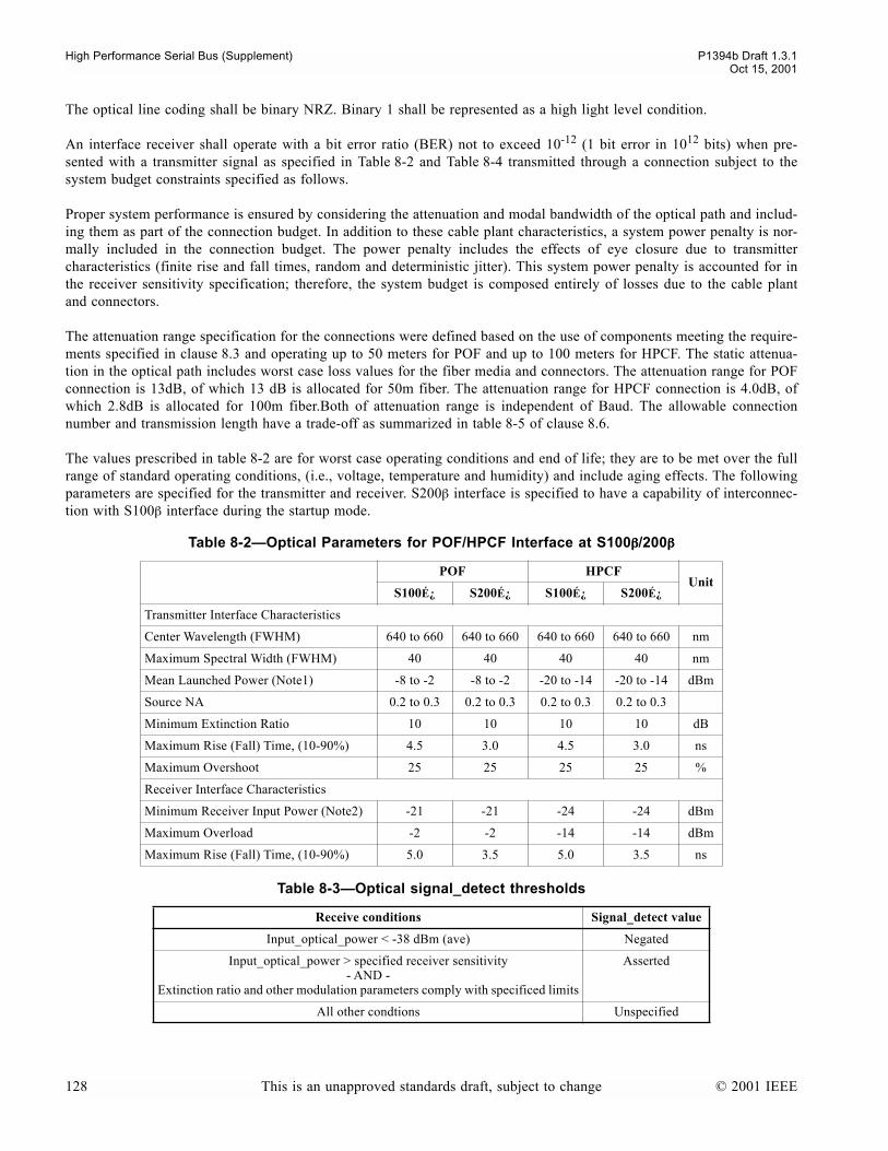
High Performance Serial Bus (Supplement) P1394b Draft 1.3.1Oct 15, 2001
The optical line coding shall be binary NRZ. Binary 1 shall be represented as a high light level condition.
An interface receiver shall operate with a bit error ratio (BER) not to exceed 10-12 (1 bit error in 1012 bits) when pre-sented with a transmitter signal as specified in Table 8-2 and Table 8-4 transmitted through a connection subject to thesystem budget constraints specified as follows.
Proper system performance is ensured by considering the attenuation and modal bandwidth of the optical path and includ-ing them as part of the connection budget. In addition to these cable plant characteristics, a system power penalty is nor-mally included in the connection budget. The power penalty includes the effects of eye closure due to transmittercharacteristics (finite rise and fall times, random and deterministic jitter). This system power penalty is accounted for inthe receiver sensitivity specification; therefore, the system budget is composed entirely of losses due to the cable plantand connectors.
The attenuation range specification for the connections were defined based on the use of components meeting the require-ments specified in clause 8.3 and operating up to 50 meters for POF and up to 100 meters for HPCF. The static attenua-tion in the optical path includes worst case loss values for the fiber media and connectors. The attenuation range for POFconnection is 13dB, of which 13 dB is allocated for 50m fiber. The attenuation range for HPCF connection is 4.0dB, ofwhich 2.8dB is allocated for 100m fiber.Both of attenuation range is independent of Baud. The allowable connectionnumber and transmission length have a trade-off as summarized in table 8-5 of clause 8.6.
The values prescribed in table 8-2 are for worst case operating conditions and end of life; they are to be met over the fullrange of standard operating conditions, (i.e., voltage, temperature and humidity) and include aging effects. The followingparameters are specified for the transmitter and receiver. S200β interface is specified to have a capability of interconnec-tion with S100β interface during the startup mode.
Table 8-2Optical Parameters for POF/HPCF Interface at S100ββββ/200ββββ
POF HPCFUnit
S100É¿ S200É¿ S100É¿ S200É¿
Transmitter Interface Characteristics
Center Wavelength (FWHM) 640 to 660 640 to 660 640 to 660 640 to 660 nm
Maximum Spectral Width (FWHM) 40 40 40 40 nm
Mean Launched Power (Note1) -8 to -2 -8 to -2 -20 to -14 -20 to -14 dBm
Source NA 0.2 to 0.3 0.2 to 0.3 0.2 to 0.3 0.2 to 0.3
Minimum Extinction Ratio 10 10 10 10 dB
Maximum Rise (Fall) Time, (10-90%) 4.5 3.0 4.5 3.0 ns
Maximum Overshoot 25 25 25 25 %
Receiver Interface Characteristics
Minimum Receiver Input Power (Note2) -21 -21 -24 -24 dBm
Maximum Overload -2 -2 -14 -14 dBm
Maximum Rise (Fall) Time, (10-90%) 5.0 3.5 5.0 3.5 ns
Table 8-3Optical signal_detect thresholds
Receive conditions Signal_detect value
Input_optical_power < -38 dBm (ave) Negated
Input_optical_power > specified receiver sensitivity- AND -
Extinction ratio and other modulation parameters comply with specificed limits
Asserted
All other condtions Unspecified
128 This is an unapproved standards draft, subject to change © 2001 IEEE
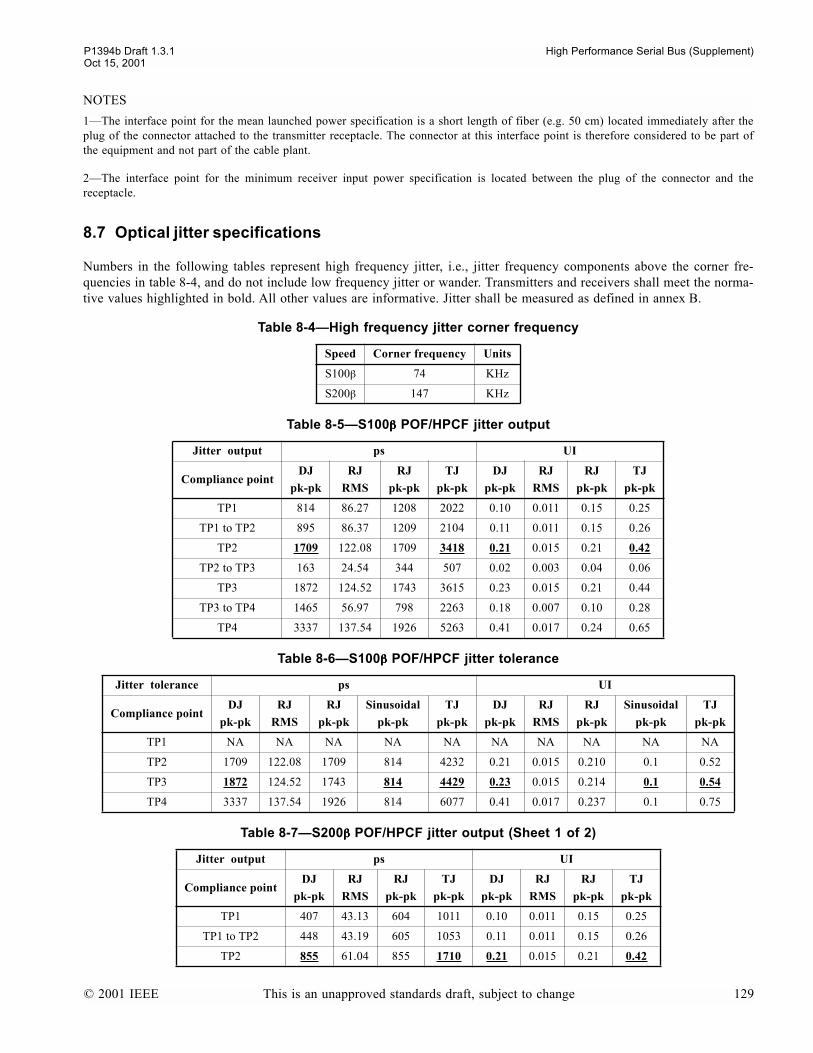
P1394b Draft 1.3.1 High Performance Serial Bus (Supplement)Oct 15, 2001
NOTES
1The interface point for the mean launched power specification is a short length of fiber (e.g. 50 cm) located immediately after theplug of the connector attached to the transmitter receptacle. The connector at this interface point is therefore considered to be part ofthe equipment and not part of the cable plant.
2The interface point for the minimum receiver input power specification is located between the plug of the connector and thereceptacle.
8.7 Optical jitter specifications
Numbers in the following tables represent high frequency jitter, i.e., jitter frequency components above the corner fre-quencies in table 8-4, and do not include low frequency jitter or wander. Transmitters and receivers shall meet the norma-tive values highlighted in bold. All other values are informative. Jitter shall be measured as defined in annex B.
Table 8-4High frequency jitter corner frequency
Speed Corner frequency Units
S100β 74 KHz
S200β 147 KHz
Table 8-5S100ββββ POF/HPCF jitter output
Jitter output ps UI
Compliance pointDJ
pk-pk
RJ
RMS
RJ
pk-pk
TJ
pk-pk
DJ
pk-pk
RJ
RMS
RJ
pk-pk
TJ
pk-pk
TP1 814 86.27 1208 2022 0.10 0.011 0.15 0.25
TP1 to TP2 895 86.37 1209 2104 0.11 0.011 0.15 0.26
TP2 1709 122.08 1709 3418 0.21 0.015 0.21 0.42
TP2 to TP3 163 24.54 344 507 0.02 0.003 0.04 0.06
TP3 1872 124.52 1743 3615 0.23 0.015 0.21 0.44
TP3 to TP4 1465 56.97 798 2263 0.18 0.007 0.10 0.28
TP4 3337 137.54 1926 5263 0.41 0.017 0.24 0.65
Table 8-6S100ββββ POF/HPCF jitter tolerance
Jitter tolerance ps UI
Compliance pointDJ
pk-pk
RJ
RMS
RJ
pk-pk
Sinusoidal
pk-pk
TJ
pk-pk
DJ
pk-pk
RJ
RMS
RJ
pk-pk
Sinusoidal
pk-pk
TJ
pk-pk
TP1 NA NA NA NA NA NA NA NA NA NA
TP2 1709 122.08 1709 814 4232 0.21 0.015 0.210 0.1 0.52
TP3 1872 124.52 1743 814 4429 0.23 0.015 0.214 0.1 0.54
TP4 3337 137.54 1926 814 6077 0.41 0.017 0.237 0.1 0.75
Table 8-7S200ββββ POF/HPCF jitter output (Sheet 1 of 2)
Jitter output ps UI
Compliance pointDJ
pk-pk
RJ
RMS
RJ
pk-pk
TJ
pk-pk
DJ
pk-pk
RJ
RMS
RJ
pk-pk
TJ
pk-pk
TP1 407 43.13 604 1011 0.10 0.011 0.15 0.25
TP1 to TP2 448 43.19 605 1053 0.11 0.011 0.15 0.26
TP2 855 61.04 855 1710 0.21 0.015 0.21 0.42
© 2001 IEEE This is an unapproved standards draft, subject to change 129
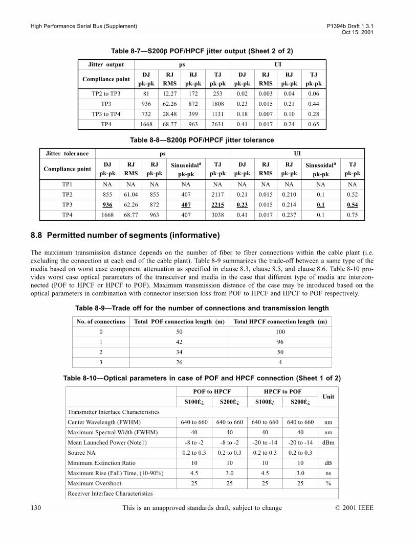
High Performance Serial Bus (Supplement) P1394b Draft 1.3.1Oct 15, 2001
8.8 Permitted number of segments (informative)
The maximum transmission distance depends on the number of fiber to fiber connections within the cable plant (i.e.excluding the connection at each end of the cable plant). Table 8-9 summarizes the trade-off between a same type of themedia based on worst case component attenuation as specified in clause 8.3, clause 8.5, and clause 8.6. Table 8-10 pro-vides worst case optical parameters of the transceiver and media in the case that different type of media are intercon-nected (POF to HPCF or HPCF to POF). Maximum transmission distance of the case may be inroduced based on theoptical parameters in combination with connector insersion loss from POF to HPCF and HPCF to POF respectively.
TP2 to TP3 81 12.27 172 253 0.02 0.003 0.04 0.06
TP3 936 62.26 872 1808 0.23 0.015 0.21 0.44
TP3 to TP4 732 28.48 399 1131 0.18 0.007 0.10 0.28
TP4 1668 68.77 963 2631 0.41 0.017 0.24 0.65
Table 8-8S200ββββ POF/HPCF jitter tolerance
Jitter tolerance ps UI
Compliance pointDJ
pk-pk
RJ
RMS
RJ
pk-pkSinusoidala
pk-pk
TJ
pk-pk
DJ
pk-pk
RJ
RMS
RJ
pk-pkSinusoidala
pk-pk
TJ
pk-pk
TP1 NA NA NA NA NA NA NA NA NA NA
TP2 855 61.04 855 407 2117 0.21 0.015 0.210 0.1 0.52
TP3 936 62.26 872 407 2215 0.23 0.015 0.214 0.1 0.54
TP4 1668 68.77 963 407 3038 0.41 0.017 0.237 0.1 0.75
Table 8-9Trade off for the number of connections and transmission length
No. of connections Total POF connection length (m) Total HPCF connection length (m)
0 50 100
1 42 96
2 34 50
3 26 4
Table 8-10Optical parameters in case of POF and HPCF connection (Sheet 1 of 2)
POF to HPCF HPCF to POFUnit
S100É¿ S200É¿ S100É¿ S200É¿
Transmitter Interface Characteristics
Center Wavelength (FWHM) 640 to 660 640 to 660 640 to 660 640 to 660 nm
Maximum Spectral Width (FWHM) 40 40 40 40 nm
Mean Launched Power (Note1) -8 to -2 -8 to -2 -20 to -14 -20 to -14 dBm
Source NA 0.2 to 0.3 0.2 to 0.3 0.2 to 0.3 0.2 to 0.3
Minimum Extinction Ratio 10 10 10 10 dB
Maximum Rise (Fall) Time, (10-90%) 4.5 3.0 4.5 3.0 ns
Maximum Overshoot 25 25 25 25 %
Receiver Interface Characteristics
Table 8-7S200ββββ POF/HPCF jitter output (Sheet 2 of 2)
Jitter output ps UI
Compliance pointDJ
pk-pk
RJ
RMS
RJ
pk-pk
TJ
pk-pk
DJ
pk-pk
RJ
RMS
RJ
pk-pk
TJ
pk-pk
130 This is an unapproved standards draft, subject to change © 2001 IEEE

P1394b Draft 1.3.1 High Performance Serial Bus (Supplement)Oct 15, 2001
Minimum Receiver Input Power (Note2) -24 -24 -21 -21 dBm
Maximum Overload -14 -14 -2 -2 dBm
Maximum Rise (Fall) Time, (10-90%) 5.0 3.5 5.0 3.5 ns
Table 8-10Optical parameters in case of POF and HPCF connection (Sheet 2 of 2)
POF to HPCF HPCF to POFUnit
S100É¿ S200É¿ S100É¿ S200É¿
© 2001 IEEE This is an unapproved standards draft, subject to change 131

High Performance Serial Bus (Supplement) P1394b Draft 1.3.1Oct 15, 2001
132 This is an unapproved standards draft, subject to change © 2001 IEEE

P1394b Draft 1.3.1 High Performance Serial Bus (Supplement)Oct 15, 2001
9. Category 5 UTP physical medium dependent specfication
The alternative long distance physical layer specified by this section enables signaling over Category 5 UnshieldedTwisted Pair (UTP) cable at the S100β data rate.
Figure 9-1 shows the relationship of this clause to the PHY master architecture.
9.1 Overview
This clause specifies the physical media dependent (PMD) sublayer for CAT-5 UTP connections for the data rate ofS100β. The PMD provides all of the services required to transport a suitably coded digital bit stream across the connec-tion segment.
Figure 9-1PHY master architecture (CAT-5 UTP PMD in context)
BOSS arbitration and control state machines.
Cat. 5 UTP
Link
B PHY
PHY-Link interface
packet transmit/receive
port controller
DS mode functions
Beta mode
functions
Connection management
Low power signaling
Port
to other ports
pa
cke
t d
ata
send LTP PHY packets
req
ue
st\
gra
nt
packet control
request/grant, enable LTP RX flags
TX/RX symbol,port status
TX/RX symbol
TX/RX symbol,enables
con
tro
l
con
figco
ntr
ol
po
rtst
atu
s
PMD
Cat. 5 UTP
PMD
DS mode functions
Beta mode
functions
Connection management
Low power signaling
Port
PHY packets
TX/RX data signals, PMD control/status,arb/connect control/status (DS only)
TX/RX data signals, PMD control/status,arb/connect control/status (DS only)
© 2001 IEEE This is an unapproved standards draft, subject to change 133
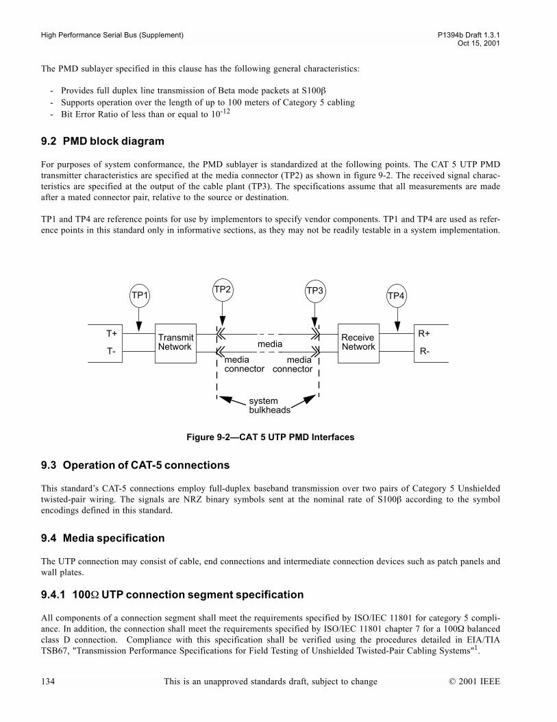
High Performance Serial Bus (Supplement) P1394b Draft 1.3.1Oct 15, 2001
The PMD sublayer specified in this clause has the following general characteristics:
- Provides full duplex line transmission of Beta mode packets at S100β- Supports operation over the length of up to 100 meters of Category 5 cabling - Bit Error Ratio of less than or equal to 10-12
9.2 PMD block diagram
For purposes of system conformance, the PMD sublayer is standardized at the following points. The CAT 5 UTP PMDtransmitter characteristics are specified at the media connector (TP2) as shown in figure 9-2. The received signal charac-teristics are specified at the output of the cable plant (TP3). The specifications assume that all measurements are madeafter a mated connector pair, relative to the source or destination.
TP1 and TP4 are reference points for use by implementors to specify vendor components. TP1 and TP4 are used as refer-ence points in this standard only in informative sections, as they may not be readily testable in a system implementation.
9.3 Operation of CAT-5 connections
This standards CAT-5 connections employ full-duplex baseband transmission over two pairs of Category 5 Unshieldedtwisted-pair wiring. The signals are NRZ binary symbols sent at the nominal rate of S100β according to the symbolencodings defined in this standard.
9.4 Media specification
The UTP connection may consist of cable, end connections and intermediate connection devices such as patch panels andwall plates.
9.4.1 100Ω UTP connection segment specification
All components of a connection segment shall meet the requirements specified by ISO/IEC 11801 for category 5 compli-ance. In addition, the connection shall meet the requirements specified by ISO/IEC 11801 chapter 7 for a 100Ω balancedclass D connection. Compliance with this specification shall be verified using the procedures detailed in EIA/TIATSB67, "Transmission Performance Specifications for Field Testing of Unshielded Twisted-Pair Cabling Systems"1.
Figure 9-2CAT 5 UTP PMD Interfaces
T+
T-
R+
R-
TP1TP2 TP3
TP4
media mediaconnector connector
media
systembulkheads
Transmit Network
Receive Network
134 This is an unapproved standards draft, subject to change © 2001 IEEE
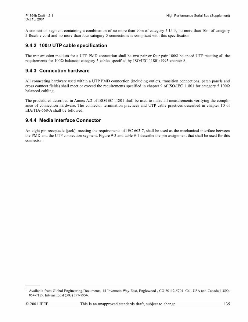
P1394b Draft 1.3.1 High Performance Serial Bus (Supplement)Oct 15, 2001
A connection segment containing a combination of no more than 90m of category 5 UTP, no more than 10m of category5 flexible cord and no more than four category 5 connections is compliant with this specification.
9.4.2 100Ω UTP cable specification
The transmission medium for a UTP PMD connection shall be two pair or four pair 100Ω balanced UTP meeting all therequirements for 100Ω balanced category 5 cables specified by ISO/IEC 11801:1995 chapter 8.
9.4.3 Connection hardware
All connecting hardware used within a UTP PMD connection (including outlets, transition connections, patch panels andcross connect fields) shall meet or exceed the requirements specified in chapter 9 of ISO/IEC 11801 for category 5 100Ωbalanced cabling.
The procedures described in Annex A.2 of ISO/IEC 11801 shall be used to make all measurements verifying the compli-ance of connection hardware. The connector termination practices and UTP cable practices described in chapter 10 ofEIA/TIA-568-A shall be followed.
9.4.4 Media Interface Connector
An eight pin receptacle (jack), meeting the requirements of IEC 603-7, shall be used as the mechanical interface betweenthe PMD and the UTP connection segment. Figure 9-3 and table 9-1 describe the pin assignment that shall be used for thisconnector
1 Available from Global Engineering Documents, 14 Inverness Way East, Englewood , CO 80112-5704. Call USA and Canada 1-800-854-7179, International (303) 397-7956.
.
© 2001 IEEE This is an unapproved standards draft, subject to change 135
High Performance Serial Bus (Supplement) P1394b Draft 1.3.1Oct 15, 2001
The connection segment shall be terminated at each end with an eight pin plug, meeting the requirements of IEC 603-7.A crossover, when provided, shall connect pins 1 and 2 of the media interface connection segment to pins 7 and 8 respec-tively at the other end of the connection segment, and vice versa. When no crossover is provided, pins 1, 2, 7 and 8 of themedia interface connection segment shall be connected to pins 1, 2, 7 and 8 respectively at the other end of the connec-tion segment.
9.4.5 Autocrossover
The PMD shall support an autocrossover function, controlled by PMD_CONTROL_request.
On power reset, and after a PMD_CONTROL.request(PMD_NO_CROSSOVER) from the Connection Management func-tion, the PMD shall transmit on TPB and TPB* (pins 1 and 2 respectively on the Media Interface Connector) and shallreceive on TPA and TPA* (pins 7 and 8 respectively on the Media Interface Connector).
After a PMD_CONTROL.request(PMD_CROSSOVER) from the Connection Management function, the PMD shall trans-mit on TPA and TPA* (pins 7 and 8 respectively on the Media Interface Connector) and shall receive on TPB and TPB*(pins 1 and 2 respectively on the Media Interface Connector).
The PMD shall report PH_ AUTOCROSSOVER_SUPPORTED in response to a PMD_STATUS.request from the Con-nection Management function.
9.5 PMD electrical specifications
9.5.1 Galvanic isolation
A coupling transformer is normally used within a UTP PMD to electrically isolate the PHY and the UTP cable plant. TheUTP PMD shall provide electrical isolation according to at least one of the following electrical strength tests:
a) 1500 V rms at 50 Hz to 60 Hz for 60 seconds, applied as specified in Section 5.3.2 of IEC Publication 950.
Figure 9-3Media interface connector
Table 9-1Media Interface connector pin assignments
Pin Circuit
1 TPB
2 TPB*
3
4
5
6
7 TPA
8 TPA*
1 2 3 4 5 6 7 8
136 This is an unapproved standards draft, subject to change © 2001 IEEE

P1394b Draft 1.3.1 High Performance Serial Bus (Supplement)Oct 15, 2001
b) 2250 V dc for 60 seconds, applied as specified in Section 5.3.2 of IEC Publication 950.c) A sequence of ten 2400 V impulses of alternating polarity, applied at intervals of not less than 1 second. The
shape of the impulses shall be 1.2/50 ms (1.2 ms virtual front time, 50 ms virtual time or half value) as defined inIEC Publication 60.
There shall be no insulation breakdown, as defined in Section 5.3.2 of IEC Publication 950, during the test. The resistanceafter the test shall be at least 2 Megaohms, measured at 500 V dc.
9.5.2 Transmitter specifications
The signal measured at the output of the UTP PMD media interface connector shall meet the requirements of table 9-2.
Provisional: In addition, the signal shall satisfy the requirements of the signal mask shown in figure 9-4 and calibrated intable 9-3 while the PMD is transmitting a continuously repeating D0.0 character. This character contains a sequence ofthree consecutive 1 symbols. This sequence of three 1s shall be compared with the signal mask shown in figure 3.
NOTEA sequence of repeating D0.0 characters is generated whenever the port has its transmit scrambler disabled and is generatinga REQ(training) signal.
NOTES
1While this specification is intended to enable compliance with regulations concerning RF emissions, it is not intended to ensurecompliance with these regulations. The implementor should consider any applicable local, national or international regulations.
2Output balance is defined as the ratio of differential voltage to common mode voltage at the output of the transmitter.
3(Editorial) The provisional rise and fall time specification numbers are drawn from the FDDI TP-PMD standard
Table 9-2UTP transmitter electrical specifications
Parameter Requirement Units
Amplitude(peak to peak)
Max 1050 mV
Min 950 mV
Amplitude(differential)
Max 525 mV
Min 475 mV
Max(OFF) 45 mV
Rise/fall time
Max 4.4 ns
Min 3.0 ns
Differential skew 200 ps
Jitter 2 ns pk-pk
Output balance
0.1-30MHz >45 dB
30-60MHz >40 dB
60-100MHz >35 dB
Return loss >20 dB
© 2001 IEEE This is an unapproved standards draft, subject to change 137

High Performance Serial Bus (Supplement) P1394b Draft 1.3.1Oct 15, 2001
9.5.3 Receiver specifications
9.5.3.1 Receiver input signals
A UTP PMD receiver shall be capable of recovering data with a Bit Error Ratio of better than or equal to 1 in 1012 whenreceiving signals from the output of a worst case connection segment. The worst case connection segment shall consist ofan appropriate length of cable and number of connections, such that the connection attenuation is equivalent to that spec-ified by ISO/IEC 11801 chapter 7 for a 100Ω balanced class D connection.
The receiver shall also be capable of recovering data with a Bit Error Ratio of better than or equal to 1 in 1012 whenreceiving signals from the output of a connection segment comprising any length of category 5 UTP cable up to 100m,and any number of connections up to a maximum of 4.
Figure 9-4Signal mask for transmitted signal
Table 9-3Coordinates for signal mask
X label X value (ns) Y label Y value (volts)
X1 0.00 Y1 -0.26
X2 1.75 Y2 -0.23
X3 3.50 Y3 -0.02
X4 6.00 Y4 0.02
X5 21.50 Y5 0.26
X6 24.00
X7 25.75
X8 27.50
X1 X2 X3 X4 X5 X6 X7 X8
Y1
Y2
Y3
Y4
Y5
138 This is an unapproved standards draft, subject to change © 2001 IEEE
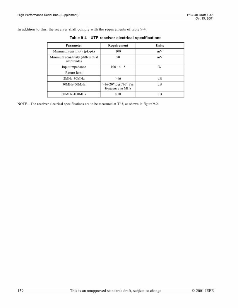
High Performance Serial Bus (Supplement) P1394b Draft 1.3.1Oct 15, 2001
In addition to this, the receiver shall comply with the requirements of table 9-4.
NOTEThe receiver electrical specifications are to be measured at TP3, as shown in figure 9-2.
Table 9-4UTP receiver electrical specifications
Parameter Requirement Units
Minimum sensitivity (pk-pk) 100 mV
Minimum sensitivity (differential amplitude)
50 mV
Input impedance 100 +/- 15 W
Return loss:
2MHz-30MHz >16 dB
30MHz-60MHz >16-20*log(f/30), f is frequency in MHz
dB
60MHz-100MHz >10 dB
139 This is an unapproved standards draft, subject to change © 2001 IEEE
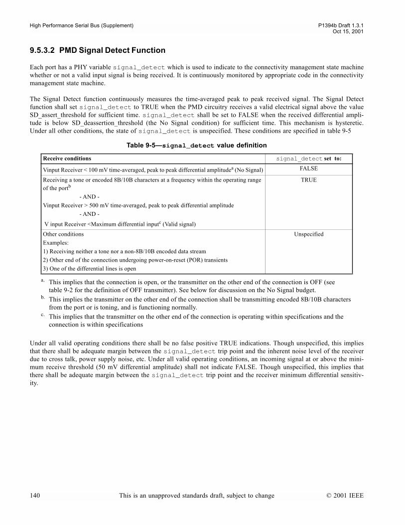
High Performance Serial Bus (Supplement) P1394b Draft 1.3.1Oct 15, 2001
9.5.3.2 PMD Signal Detect Function
Each port has a PHY variable signal_detect which is used to indicate to the connectivity management state machinewhether or not a valid input signal is being received. It is continuously monitored by appropriate code in the connectivitymanagement state machine.
The Signal Detect function continuously measures the time-averaged peak to peak received signal. The Signal Detectfunction shall set signal_detect to TRUE when the PMD circuitry receives a valid electrical signal above the valueSD_assert_threshold for sufficient time. signal_detect shall be set to FALSE when the received differential ampli-tude is below SD_deassertion_threshold (the No Signal condition) for sufficient time. This mechanism is hysteretic.Under all other conditions, the state of signal_detect is unspecified. These conditions are specified in table 9-5
Under all valid operating conditions there shall be no false positive TRUE indications. Though unspecified, this impliesthat there shall be adequate margin between the signal_detect trip point and the inherent noise level of the receiverdue to cross talk, power supply noise, etc. Under all valid operating conditions, an incoming signal at or above the mini-mum receive threshold (50 mV differential amplitude) shall not indicate FALSE. Though unspecified, this implies thatthere shall be adequate margin between the signal_detect trip point and the receiver minimum differential sensitiv-ity.
Table 9-5signal_detect value definition
Receive conditions signal_detect set to:
Vinput Receiver < 100 mV time-averaged, peak to peak differential amplitudea (No Signal)
a. This implies that the connection is open, or the transmitter on the other end of the connection is OFF (see table 9-2 for the definition of OFF transmitter). See below for discussion on the No Signal budget.
FALSE
Receiving a tone or encoded 8B/10B characters at a frequency within the operating range of the portb
- AND -
Vinput Receiver > 500 mV time-averaged, peak to peak differential amplitude
- AND -
V input Receiver <Maximum differential inputc (Valid signal)
b. This implies the transmitter on the other end of the connection shall be transmitting encoded 8B/10B characters from the port or is toning, and is functioning normally.
c. This implies that the transmitter on the other end of the connection is operating within specifications and the connection is within specifications
TRUE
Other conditions
Examples:
1) Receiving neither a tone nor a non-8B/10B encoded data stream
2) Other end of the connection undergoing power-on-reset (POR) transients
3) One of the differential lines is open
Unspecified
140 This is an unapproved standards draft, subject to change © 2001 IEEE

P1394b Draft 1.3.1 High Performance Serial Bus (Supplement)Oct 15, 2001
The parameters for the response times are defined in figure 9-5 and specified in table 9-6
9.6 PMD implementation (informative)
The CAT 5 UTP PMD has a specification that is similar to those contained in other standards documents supporting 100mof category 5 UTP, such as ANSI X3.263-1995 (Fibre Distributed Data Interface - Token Ring Twisted Pair PhysicalLayer Medium Dependent (TP-PMD)) and AF-PHY-0015.000 (ATM Physical Medium Dependent Interface Specificationfor 155Mb/s over Twisted Pair Cable). While the CAT 5 UTP PMD is compatible with all the logical functions of the BPHY (e.g. 8B/10B coding, scrambling), implementation of the CAT 5 UTP PMD is likely to require further active com-ponents (e.g. line drivers, equalizer circuits) in addition to a Beta capable PHY device that provides the standard electricalinterface specified in clause 5. In this respect, it is envisaged that the CAT 5 UTP PMD may be implemented using tech-nology similar to that developed for the standards referenced above. However, use of such technology is not necessaryfor compliance with this standard, nor does it guarantee compliance with this standard.
Figure 9-5signal_detect timing parameters
Table 9-6signal_detect timing
Symbol Parameter Unit Min Max
t_sd_on Delay from valid signal to assertion of signal_detect msec - 0.5
t_sd_off Delay from no signal to negation of signal_detect msec - t_sd_on
Occurrence of valid signal
signal_detect
t_sd_on t_sd_off
Occurrence of no signal
© 2001 IEEE This is an unapproved standards draft, subject to change 141

High Performance Serial Bus (Supplement) P1394b Draft 1.3.1Oct 15, 2001
142 This is an unapproved standards draft, subject to change © 2001 IEEE

P1394b Draft 1.3.1 High Performance Serial Bus (Supplement)Oct 15, 2001
10. Beta mode port specification
This standard leaves all specifications related to DS mode operation unchanged from IEEE 1394.
This section specifies the functions and operation of a port when operating in Beta mode.
10.1 Overview
The relationship and interfaces between the Beta mode port functions and other functions and layers are illustrated infigure 10-1:
Figure 10-1PHY master architecture (Data routing, arbitration and control interfaces in context)
BOSS arbitration and control token
machines.
Cat. 5 UTP - or -Glass optical fiber -or-
Plastic optical fiber -or -Beta-only electrical -or-Bilingual electrical -or -
DS-only electrical
Link
B PHY
PHY-Link interface
packet transmit/receive
port controller
DS mode functions
Beta mode
functions
Connection management
Low power signaling
Port
to other ports
pa
cke
t d
ata
send LTP PHY packets
req
ue
st\
gra
nt
packet control
request/grant, enable LTP RX flags
TX/RX symbol,port status
TX/RX symbol
TX/RX symbol,enables
con
tro
l
con
figco
ntr
ol
po
rtst
atu
s
PMD Cat. 5 UTP - or -Glass optical fiber -or-
Plastic optical fiber -or -Beta-only electrical -or-Bilingual electrical -or -
DS-only electrical
PMD
DS mode functions
Beta mode
functions
Connection management
Low power signaling
Port
PHY packets
TX/RX data signals, PMD control/status,arb/connect control/status (DS only)
TX/RX data signals, PMD control/status,arb/connect control/status (DS only)
© 2001 IEEE This is an unapproved standards draft, subject to change 143

High Performance Serial Bus (Supplement) P1394b Draft 1.3.1Oct 15, 2001
When operating in Beta mode, a port accepts data, control and arbitration signals from the Arbitration State Machine (andalso from the ports connection management machine as the port transitions to and from the On state), scrambles them,encodes them into 10-bit symbols for transmission and delivers the result as a bit stream to the Physical Medium Depen-dent layer for onward transmission to the peer port. Simultaneously, the port accepts an incoming bit-stream from thePhysical Medium Dependent layer (received from the peer port), deserialize it into 10 bit symbols, decodes and descram-bles these and places the resulting data, control and arbitration signal in the ports receive FIFO, which is used to retimethe incoming stream to the local clock. The incoming signals are in due course processed by the backgroundprocess_requests function. The port carries out these functions whenever and for as long as the ports bport_onsignal is set to TRUE (set and reset by the Connection Management State machine). When bport_on is set TRUE, theport engages in the symbol and scrambler synchronization of the encoded bit stream with its peer.
10.2 Port functions
10.2.1 Port functions overview
The port provides transmit and receive functions for formatting data as it passes between the arbitration state machine andthe PMD. In the transmitting direction, data and control signals are both scrambled and mapped to characters which arein turn passed to the PMD layer, as illustrated in figure 10-2. Each character comprises 10 bits. Transitions between dataand control signals occur at the boundaries of these characters. Two distinct code tables are defined for mapping signalsto characters. These two code tables are also used for decoding signals received from the PMD layer.
Data are scrambled and then coded using an 8B/10B block code. The rate at which bits are passed to the PMD layer istherefore 1.25 times the data rate.
144 This is an unapproved standards draft, subject to change © 2001 IEEE

P1394b Draft 1.3.1 High Performance Serial Bus (Supplement)Oct 15, 2001
Control tokens, which includes packet delimiters, are mapped to four bit control symbols and then also scrambled. Eachscrambled control symbol is transmitted as a 10 bit character. The time taken for a single 4-bit control symbol to be trans-mitted is equal to the time taken for a single byte of data to be transmitted.
Requests are transmitted as data bytes, and distinguished from data from their context. They are mapped to six bits of adata byte and then scrambled and coded in a similar way to data. The two remaining bits are set to zero so that arbitrationand control requests only use a subset of the data characters.
Similar, but reciprocal, functions are provided by the port in the receiving direction. Data characters are identified as rep-resenting data or requests according to the context in which they are received i.e. whether they are received within apacket or not.
Figure 10-2Scrambling and coding functions (informative)
8B/10B coder control coder
scrambler
10 10
10
Dx.y
8 4
Cz
control token
control symbol (4 bits)
PQRSABCDExxH
abcdeifghjabcdeifghj
PMD
control token mapping
control character
data byte (8 bits)
data character
parallel to serial
request mapping
request
ABCDEFGH
8B/10B coder
10
8
abcdeifghj
Dx.0 or Dx.4
PQRSABCDE00HABCDEFH
request symbol
data character
© 2001 IEEE This is an unapproved standards draft, subject to change 145
High Performance Serial Bus (Supplement) P1394b Draft 1.3.1Oct 15, 2001
10.2.2 Naming conventions
This standard adopts the following definitions and conventions in defining data scrambling and coding:
An unscrambled and un-encoded data byte contains 8 information bits (1 byte):A,B,C,D,E,F,G,H
Bits A-through-H are the most- through least-significant bits of the byte.
NOTEThe ordering of bits A-through-H as most-significant through least significant is the opposite order from that adopted in someother standards which use the same encoding scheme.
A scrambled and un-encoded data byte has 8 information bits (1 byte):A,B,C,D,E,F,G,H;
Bits A-through-H are the most- through least-significant bits of the byteThe scrambled and coded data character has 10 information bits:
a, b, c, d, e, i, f, g, h, and j (note: not strictly alphabetical ordering)Bits are transmitted as listed above (bits a-through-j are transmitted first-through-last)
This standard adopts the following definitions and conventions in defining control scrambling and coding:
An unscrambled and un-encoded control symbol contains 4 information bits:P,Q,R,S;
Bits P-through-S are the most- through least-significant bitsA scrambled and un-encoded control symbol has 4 information bits:
P,Q,RS;Bits P-through-S are the most- through least-significant bitsThe scrambled and coded control character has 10 information bits:
a, b, c, d, e, i, f, g, h, and j (note: not strictly alphabetical ordering)Bits are transmitted as listed above (bits a-through-j are transmitted first-through-last)
146 This is an unapproved standards draft, subject to change © 2001 IEEE
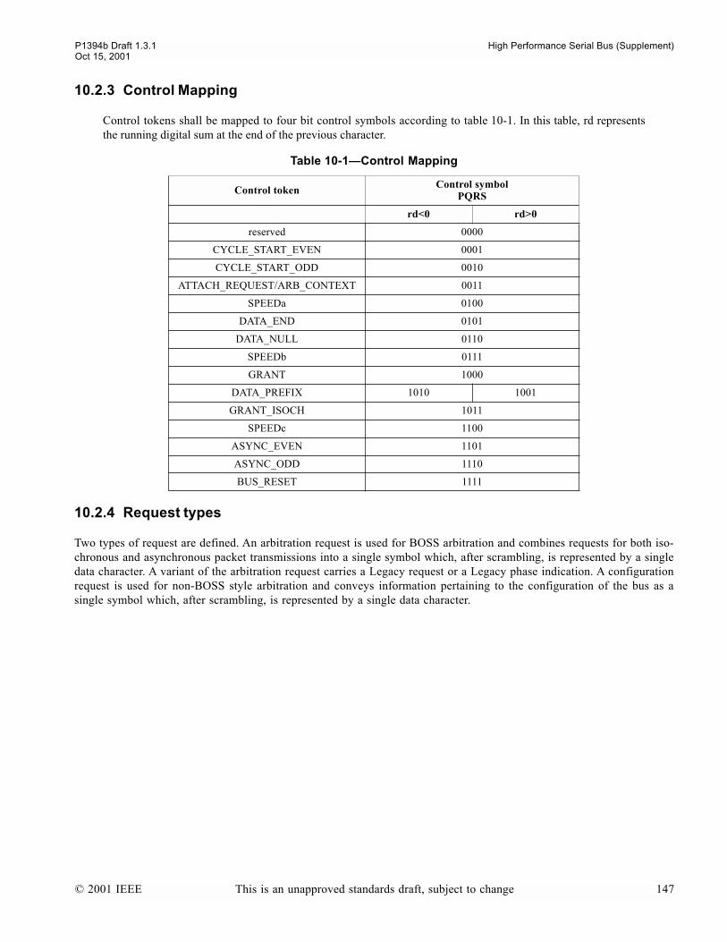
P1394b Draft 1.3.1 High Performance Serial Bus (Supplement)Oct 15, 2001
10.2.3 Control Mapping
Control tokens shall be mapped to four bit control symbols according to table 10-1. In this table, rd representsthe running digital sum at the end of the previous character.
10.2.4 Request types
Two types of request are defined. An arbitration request is used for BOSS arbitration and combines requests for both iso-chronous and asynchronous packet transmissions into a single symbol which, after scrambling, is represented by a singledata character. A variant of the arbitration request carries a Legacy request or a Legacy phase indication. A configurationrequest is used for non-BOSS style arbitration and conveys information pertaining to the configuration of the bus as asingle symbol which, after scrambling, is represented by a single data character.
Table 10-1Control Mapping
Control token Control symbolPQRS
rd<0 rd>0
reserved 0000
CYCLE_START_EVEN 0001
CYCLE_START_ODD 0010
ATTACH_REQUEST/ARB_CONTEXT 0011
SPEEDa 0100
DATA_END 0101
DATA_NULL 0110
SPEEDb 0111
GRANT 1000
DATA_PREFIX 1010 1001
GRANT_ISOCH 1011
SPEEDc 1100
ASYNC_EVEN 1101
ASYNC_ODD 1110
BUS_RESET 1111
© 2001 IEEE This is an unapproved standards draft, subject to change 147
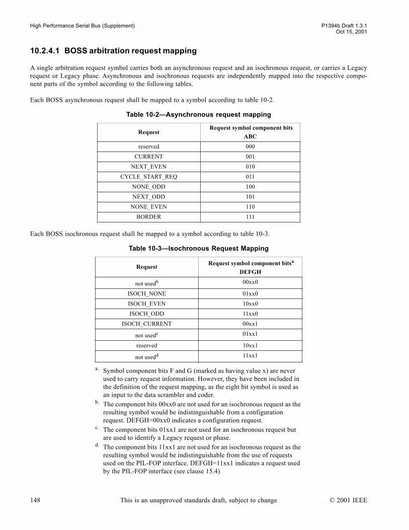
High Performance Serial Bus (Supplement) P1394b Draft 1.3.1Oct 15, 2001
10.2.4.1 BOSS arbitration request mapping
A single arbitration request symbol carries both an asynchronous request and an isochronous request, or carries a Legacyrequest or Legacy phase. Asynchronous and isochronous requests are independently mapped into the respective compo-nent parts of the symbol according to the following tables.
Each BOSS asynchronous request shall be mapped to a symbol according to table 10-2.
Each BOSS isochronous request shall be mapped to a symbol according to table 10-3.
Table 10-2Asynchronous request mapping
Request Request symbol component bits
ABC
reserved 000
CURRENT 001
NEXT_EVEN 010
CYCLE_START_REQ 011
NONE_ODD 100
NEXT_ODD 101
NONE_EVEN 110
BORDER 111
Table 10-3Isochronous Request Mapping
Request Request symbol component bitsa
DEFGH
a. Symbol component bits F and G (marked as having value x) are never used to carry request information. However, they have been included in the definition of the request mapping, as the eight bit symbol is used as an input to the data scrambler and coder.
not usedb
b. The component bits 00xx0 are not used for an isochronous request as the resulting symbol would be indistinguishable from a configuration request. DEFGH=00xx0 indicates a configuration request.
00xx0
ISOCH_NONE 01xx0
ISOCH_EVEN 10xx0
ISOCH_ODD 11xx0
ISOCH_CURRENT 00xx1
not usedc
c. The component bits 01xx1 are not used for an isochronous request but are used to identify a Legacy request or phase.
01xx1
reserved 10xx1
not usedd
d. The component bits 11xx1 are not used for an isochronous request as the resulting symbol would be indistinguishable from the use of requests used on the PIL-FOP interface. DEFGH=11xx1 indicates a request used by the PIL-FOP interface (see clause 15.4)
11xx1
148 This is an unapproved standards draft, subject to change © 2001 IEEE
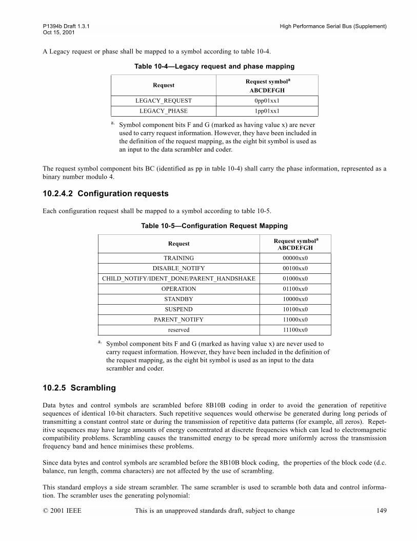
P1394b Draft 1.3.1 High Performance Serial Bus (Supplement)Oct 15, 2001
A Legacy request or phase shall be mapped to a symbol according to table 10-4.
The request symbol component bits BC (identified as pp in table 10-4) shall carry the phase information, represented as abinary number modulo 4.
10.2.4.2 Configuration requests
Each configuration request shall be mapped to a symbol according to table 10-5.
10.2.5 Scrambling
Data bytes and control symbols are scrambled before 8B10B coding in order to avoid the generation of repetitivesequences of identical 10-bit characters. Such repetitive sequences would otherwise be generated during long periods oftransmitting a constant control state or during the transmission of repetitive data patterns (for example, all zeros). Repet-itive sequences may have large amounts of energy concentrated at discrete frequencies which can lead to electromagneticcompatibility problems. Scrambling causes the transmitted energy to be spread more uniformly across the transmissionfrequency band and hence minimises these problems.
Since data bytes and control symbols are scrambled before the 8B10B block coding, the properties of the block code (d.c.balance, run length, comma characters) are not affected by the use of scrambling.
This standard employs a side stream scrambler. The same scrambler is used to scramble both data and control informa-tion. The scrambler uses the generating polynomial:
Table 10-4Legacy request and phase mapping
Request Request symbola
ABCDEFGH
a. Symbol component bits F and G (marked as having value x) are never used to carry request information. However, they have been included in the definition of the request mapping, as the eight bit symbol is used as an input to the data scrambler and coder.
LEGACY_REQUEST 0pp01xx1
LEGACY_PHASE 1pp01xx1
Table 10-5Configuration Request Mapping
Request Request symbola
ABCDEFGH
a. Symbol component bits F and G (marked as having value x) are never used to carry request information. However, they have been included in the definition of the request mapping, as the eight bit symbol is used as an input to the data scrambler and coder.
TRAINING 00000xx0
DISABLE_NOTIFY 00100xx0
CHILD_NOTIFY/IDENT_DONE/PARENT_HANDSHAKE 01000xx0
OPERATION 01100xx0
STANDBY 10000xx0
SUSPEND 10100xx0
PARENT_NOTIFY 11000xx0
reserved 11100xx0
© 2001 IEEE This is an unapproved standards draft, subject to change 149

High Performance Serial Bus (Supplement) P1394b Draft 1.3.1Oct 15, 2001
G(x) = x11 + x9 + 1
The scrambler shall generate a continuous stream of output bits at the same rate as the port operating speed during bothpacket and control transmission. These output bits are represented as a sequence of bits Scr(k) where k=0, 1, 2, 3....., suchthat Scr(k+1) is the output bit immediately following Scr(k).
The scrambler output at any point in time is defined as:
Scr(k) = Scr(k-9) XOR Scr(k-11).
Eight successive outputs of the scrambler are used to scramble a symbol, as described below. The next eight successiveoutputs of the scrambler are then used to scramble the next symbol.
Figure 10-3Representation of the scrambler as a serial bit-shift register with parallel output
10.2.5.1 Data scrambling
During packet transmission the data are scrambled using the output of the scrambler, the scrambler generates eight bits foreach byte of data to be transmitted. The scrambled data stream is the result of an exclusive OR operation on the datastream and the scrambler output.
Any data byte shall be scrambled according to the rule:
[A,B,C,D,E,F,G,H]= [A,B,C,D,E,F,G,H] XOR [Scr(k:k+7)]
Thus the most significant bit of the data byte, A, is exclusive ORed with the Scr(k); and the least significant bit of thedata byte, H, is exclusive ORed with the Scr(k+7). For example, during a sequence of data, the scrambled data byteswould be calculated as follows:
first scrambled data byte = [A,B,C,D,E,F,G,H] XOR [Scr(k:k+7)],second scrambled data byte = [A,B,C,D,E,F,G,H] XOR [Scr(k+8:k+15)], etc.
x10x9x8x7x6x5x4x3x2x1x0
XOR
scrambler output register, Scr
k+7k+6k+5k+4k+3k+2k+1k
k+7k+6k+5k+4k+3k+2k+1k
Byte clock
Operates at bit rate
Operates at byte rate
150 This is an unapproved standards draft, subject to change © 2001 IEEE
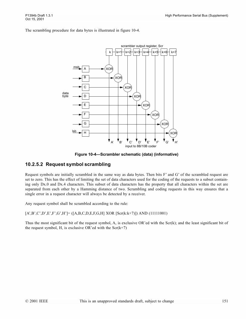
P1394b Draft 1.3.1 High Performance Serial Bus (Supplement)Oct 15, 2001
The scrambling procedure for data bytes is illustrated in figure 10-4.
10.2.5.2 Request symbol scrambling
Request symbols are initially scrambled in the same way as data bytes. Then bits F and G of the scrambled request areset to zero. This has the effect of limiting the set of data characters used for the coding of the requests to a subset contain-ing only Dx.0 and Dx.4 characters. This subset of data characters has the property that all characters within the set areseparated from each other by a Hamming distance of two. Scrambling and coding requests in this way ensures that asingle error in a request character will always be detected by a receiver.
Any request symbol shall be scrambled according to the rule:
[A,B,C,D,E,F,G,H]= ([A,B,C,D,E,F,G,H] XOR [Scr(k:k+7)]) AND (11111001)
Thus the most significant bit of the request symbol, A, is exclusive ORed with the Scr(k); and the least significant bit ofthe request symbol, H, is exclusive ORed with the Scr(k+7)
Figure 10-4Scrambler schematic (data) (informative)
scrambler output register, Scr
XOR
XOR
XOR
XOR
XOR
XOR
XOR
XOR
databyte
lsb
msb
input to 8B/10B coderA B C D E F G H
A
B
C
D
E
F
G
H
k k+1 k+2 k+3 k+4 k+5 k+6 k+7
© 2001 IEEE This is an unapproved standards draft, subject to change 151

High Performance Serial Bus (Supplement) P1394b Draft 1.3.1Oct 15, 2001
The scrambling procedure for request symbols is illustrated in figure 10-5.
10.2.5.3 Control symbol scrambling
The scrambled control symbol shall be the result of an exclusive OR operation on the control symbol and alternate bits ofthe scrambler generating polynomial.
Any control symbol shall be scrambled according to the rule:
[P,Q,R,S]= [P,Q,R,S] XOR [Scr(k),Scr(k+2),Scr(k+4),Scr(k+6)]
Figure 10-5Scrambler schematic (request symbol) (informative)
scrambler output register, Scr
XOR
XOR
XOR
XOR
XOR
XOR
databyte
lsb
msb
input to 8B/10B coderA B C D E H
A
B
C
D
E
F
G
H
k k+1 k+2 k+3 k+4 k+5 k+6 k+7
152 This is an unapproved standards draft, subject to change © 2001 IEEE
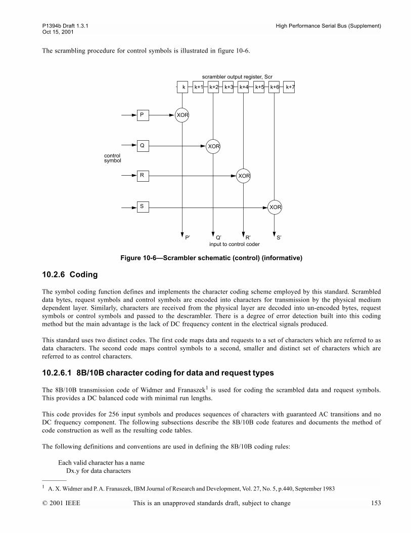
P1394b Draft 1.3.1 High Performance Serial Bus (Supplement)Oct 15, 2001
The scrambling procedure for control symbols is illustrated in figure 10-6.
10.2.6 Coding
The symbol coding function defines and implements the character coding scheme employed by this standard. Scrambleddata bytes, request symbols and control symbols are encoded into characters for transmission by the physical mediumdependent layer. Similarly, characters are received from the physical layer are decoded into un-encoded bytes, requestsymbols or control symbols and passed to the descrambler. There is a degree of error detection built into this codingmethod but the main advantage is the lack of DC frequency content in the electrical signals produced.
This standard uses two distinct codes. The first code maps data and requests to a set of characters which are referred to asdata characters. The second code maps control symbols to a second, smaller and distinct set of characters which arereferred to as control characters.
10.2.6.1 8B/10B character coding for data and request types
The 8B/10B transmission code of Widmer and Franaszek1 is used for coding the scrambled data and request symbols.This provides a DC balanced code with minimal run lengths.
This code provides for 256 input symbols and produces sequences of characters with guaranteed AC transitions and noDC frequency component. The following subsections describe the 8B/10B code features and documents the method ofcode construction as well as the resulting code tables.
The following definitions and conventions are used in defining the 8B/10B coding rules:
Each valid character has a nameDx.y for data characters
Figure 10-6Scrambler schematic (control) (informative)
1 A. X. Widmer and P. A. Franaszek, IBM Journal of Research and Development, Vol. 27, No. 5, p.440, September 1983
scrambler output register, Scr
XOR
XOR
XOR
XOR
controlsymbol
input to control coderP Q R S
P
Q
R
S
k k+1 k+2 k+3 k+4 k+5 k+6 k+7
© 2001 IEEE This is an unapproved standards draft, subject to change 153

High Performance Serial Bus (Supplement) P1394b Draft 1.3.1Oct 15, 2001
x = the 5 bit input value, base 10, for bits ABCDEy = the 3 bit input value, base 10, for bits FGH
In the following tables,rd represents the running digital sum value at the end of the previous characterrd1 represents the running digital sum value at the end of the current character
The running digital sum of the transmitter and the receiver is initialized to -1 during the port initialization process on anew connection.
10.2.6.1.1 8B/10B properties - run length and DC balance
A sequence of valid 8B/10B characters has a maximum run length of 5 bits (i.e., 5 consecutive ones or 5 consecutivezeros before a mandatory bit transition). Consequently, ample transitions are provided to aid in clock extraction by thephysical layers receiving PLLs.
Each valid 8B/10B character also has disparity of zero (i.e., same number of 1s and 0s in the character), +2 or -2. Tomaintain DC balance, the coding protocol demands that each character have opposite disparity from the preceding char-acter or zero disparity. Consequently, each non-zero disparity code character has an alternative coding with reversed dis-parity. The coder produces the correct alternating disparities by means of a running digital sum counter which controlswhich alternate output character is produced.
When initialized to a value of -1, the running digital sum after any bit in a sequence of valid data characters is constrainedto be between -3 and +3 inclusive. Furthermore, the mechanism of alternating output characters ensures that the runningdigital sum at the end of any code character is either -1 or +1. The transmitter and receiver shall both initialize theirrespective running digital sum to be -1 when the port is turned On or after exiting any implementation dependent diagnos-tic modes and shall update this to be -1 (negative) or +1 (positive) as appropriate at the end of every code character.
10.2.6.1.2 8B/10B code construction
The 8B/10B coding is defined in two stages. The first stage codes the first 5 bits of the un-encoded input byte into a 6 bitblock. This 5B/6B coder produces the 6 bit block depending upon the input bit values and the running digital sum value.The second stage codes the last 3 bits of the un-encoded byte into a 4 bit block using a 3B/4B coder. The running digitalsum value, as modified by the first coding stage, is also used for the second coding decision. Table 10-6 and table 10-7give the 5B/6B and 3B/4B coding tables, respectively, that are used for coding Dx.y characters.
Table 10-65B/6B Coding
inputs abcdei outputsrd1
inputs abcdei outputsrd1
Symbol ABCDE rd>0 rd<0 Symbol ABCDE rd>0 rd<0
D0 00000 011000 100111 -rd D16 00001 100100 011011 -rd
D1 10000 100010 011101 D17 10001 100011 rd
D2 01000 010010 101101 D18 01001 010011
D3 11000 110001 rd D19 11001 110010
D4 00100 001010 110101 -rd D20 00101 001011
D5 10100 101001 rd D21 10101 101010
D6 01100 011001 D22 01101 011010
D7 11100 000111 111000 rd D23 11101 000101 111010 -rd
D8 00010 000110 111001 -rd D24 00011 001100 110011
154 This is an unapproved standards draft, subject to change © 2001 IEEE

P1394b Draft 1.3.1 High Performance Serial Bus (Supplement)Oct 15, 2001
10.2.6.1.3 8B/10B valid data characters
Table 10-8 lists all of the valid data characters generated by passing the 256 possible input data bytes through the 5B/6Band 3B/4B coders.
NOTE the order of the entries in this table is different from that used in some other standards which use the same encoding scheme,due to the use of msb - lsb being A through H in this standard.
D9 10010 100101 rd D25 10011 100110 rd
D10 01010 010101 D26 01011 010110
D11 11010 110100 D27 11011 001001 110110 -rd
D12 00110 001101 D28 00111 001110 rd
D13 10110 101100 D29 10111 010001 101110 -rd
D14 01110 011100 D30 01111 100001 011110
D15 11110 101000 010111 -rd D31 11111 010100 101011
Table 10-73B/4B Coding
Inputs fghj outputsrd1
Symbol FGH rd>0 rd<0
Dx.0 000 0100 1011 -rd
Dx.1 100 1001 rd
Dx.2 010 0101
Dx.3 110 0011 1100 rd
Dx.4 001 0010 1101 -rd
Dx.5 101 1010 rd
Dx.6 011 0110
Dx.P7 111 0001 1110 -rd
Dx.A7 111 1000 0111
A7 replaces P7 if the following is true: (rd<0)? (e==1 && i==1): (e==0 && i==0)
Table 10-8Valid Data Characters (Sheet 1 of 5)
input abcdei fghj output input abcdei fghj output
NameABCDEFGH rd<0 rd>0
NameABCDEFGH rd<0 rd>0
i data_table[i][0] data_table[i][1] i data_table[i][0] data_table[i][1]
D0.0 00000 000 100111 0100 011000 1011 D4.0 00100 000 110101 0100 001010 1011
D0.4 00000 001 100111 0010 011000 1101 D4.4 00100 001 110101 0010 001010 1101
D0.2 00000 010 100111 0101 011000 0101 D4.2 00100 010 110101 0101 001010 0101
D0.6 00000 011 100111 0110 011000 0110 D4.6 00100 011 110101 0110 001010 0110
D0.1 00000 100 100111 1001 011000 1001 D4.1 00100 100 110101 1001 001010 1001
D0.5 00000 101 100111 1010 011000 1010 D4.5 00100 101 110101 1010 001010 1010
D0.3 00000 110 100111 0011 011000 1100 D4.3 00100 110 110101 0011 001010 1100
D0.7 00000 111 100111 0001 011000 1110 D4.7 00100 111 110101 0001 001010 1110
D16.0 00001 000 011011 0100 100100 1011 D20.0 00101 000 001011 1011 001011 0100
D16.4 00001 001 011011 0010 100100 1101 D20.4 00101 001 001011 1101 001011 0010
Table 10-65B/6B Coding
inputs abcdei outputsrd1
inputs abcdei outputsrd1
Symbol ABCDE rd>0 rd<0 Symbol ABCDE rd>0 rd<0
© 2001 IEEE This is an unapproved standards draft, subject to change 155
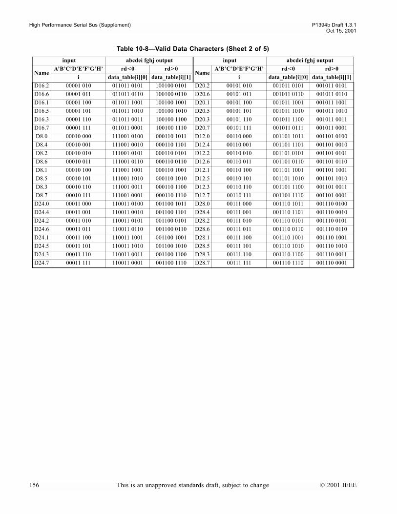
High Performance Serial Bus (Supplement) P1394b Draft 1.3.1Oct 15, 2001
D16.2 00001 010 011011 0101 100100 0101 D20.2 00101 010 001011 0101 001011 0101
D16.6 00001 011 011011 0110 100100 0110 D20.6 00101 011 001011 0110 001011 0110
D16.1 00001 100 011011 1001 100100 1001 D20.1 00101 100 001011 1001 001011 1001
D16.5 00001 101 011011 1010 100100 1010 D20.5 00101 101 001011 1010 001011 1010
D16.3 00001 110 011011 0011 100100 1100 D20.3 00101 110 001011 1100 001011 0011
D16.7 00001 111 011011 0001 100100 1110 D20.7 00101 111 001011 0111 001011 0001
D8.0 00010 000 111001 0100 000110 1011 D12.0 00110 000 001101 1011 001101 0100
D8.4 00010 001 111001 0010 000110 1101 D12.4 00110 001 001101 1101 001101 0010
D8.2 00010 010 111001 0101 000110 0101 D12.2 00110 010 001101 0101 001101 0101
D8.6 00010 011 111001 0110 000110 0110 D12.6 00110 011 001101 0110 001101 0110
D8.1 00010 100 111001 1001 000110 1001 D12.1 00110 100 001101 1001 001101 1001
D8.5 00010 101 111001 1010 000110 1010 D12.5 00110 101 001101 1010 001101 1010
D8.3 00010 110 111001 0011 000110 1100 D12.3 00110 110 001101 1100 001101 0011
D8.7 00010 111 111001 0001 000110 1110 D12.7 00110 111 001101 1110 001101 0001
D24.0 00011 000 110011 0100 001100 1011 D28.0 00111 000 001110 1011 001110 0100
D24.4 00011 001 110011 0010 001100 1101 D28.4 00111 001 001110 1101 001110 0010
D24.2 00011 010 110011 0101 001100 0101 D28.2 00111 010 001110 0101 001110 0101
D24.6 00011 011 110011 0110 001100 0110 D28.6 00111 011 001110 0110 001110 0110
D24.1 00011 100 110011 1001 001100 1001 D28.1 00111 100 001110 1001 001110 1001
D24.5 00011 101 110011 1010 001100 1010 D28.5 00111 101 001110 1010 001110 1010
D24.3 00011 110 110011 0011 001100 1100 D28.3 00111 110 001110 1100 001110 0011
D24.7 00011 111 110011 0001 001100 1110 D28.7 00111 111 001110 1110 001110 0001
Table 10-8Valid Data Characters (Sheet 2 of 5)
input abcdei fghj output input abcdei fghj output
NameABCDEFGH rd<0 rd>0
NameABCDEFGH rd<0 rd>0
i data_table[i][0] data_table[i][1] i data_table[i][0] data_table[i][1]
156 This is an unapproved standards draft, subject to change © 2001 IEEE
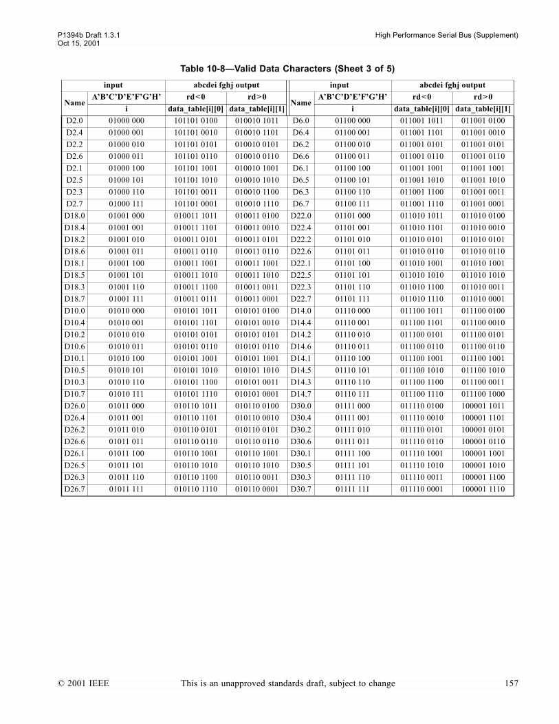
P1394b Draft 1.3.1 High Performance Serial Bus (Supplement)Oct 15, 2001
D2.0 01000 000 101101 0100 010010 1011 D6.0 01100 000 011001 1011 011001 0100
D2.4 01000 001 101101 0010 010010 1101 D6.4 01100 001 011001 1101 011001 0010
D2.2 01000 010 101101 0101 010010 0101 D6.2 01100 010 011001 0101 011001 0101
D2.6 01000 011 101101 0110 010010 0110 D6.6 01100 011 011001 0110 011001 0110
D2.1 01000 100 101101 1001 010010 1001 D6.1 01100 100 011001 1001 011001 1001
D2.5 01000 101 101101 1010 010010 1010 D6.5 01100 101 011001 1010 011001 1010
D2.3 01000 110 101101 0011 010010 1100 D6.3 01100 110 011001 1100 011001 0011
D2.7 01000 111 101101 0001 010010 1110 D6.7 01100 111 011001 1110 011001 0001
D18.0 01001 000 010011 1011 010011 0100 D22.0 01101 000 011010 1011 011010 0100
D18.4 01001 001 010011 1101 010011 0010 D22.4 01101 001 011010 1101 011010 0010
D18.2 01001 010 010011 0101 010011 0101 D22.2 01101 010 011010 0101 011010 0101
D18.6 01001 011 010011 0110 010011 0110 D22.6 01101 011 011010 0110 011010 0110
D18.1 01001 100 010011 1001 010011 1001 D22.1 01101 100 011010 1001 011010 1001
D18.5 01001 101 010011 1010 010011 1010 D22.5 01101 101 011010 1010 011010 1010
D18.3 01001 110 010011 1100 010011 0011 D22.3 01101 110 011010 1100 011010 0011
D18.7 01001 111 010011 0111 010011 0001 D22.7 01101 111 011010 1110 011010 0001
D10.0 01010 000 010101 1011 010101 0100 D14.0 01110 000 011100 1011 011100 0100
D10.4 01010 001 010101 1101 010101 0010 D14.4 01110 001 011100 1101 011100 0010
D10.2 01010 010 010101 0101 010101 0101 D14.2 01110 010 011100 0101 011100 0101
D10.6 01010 011 010101 0110 010101 0110 D14.6 01110 011 011100 0110 011100 0110
D10.1 01010 100 010101 1001 010101 1001 D14.1 01110 100 011100 1001 011100 1001
D10.5 01010 101 010101 1010 010101 1010 D14.5 01110 101 011100 1010 011100 1010
D10.3 01010 110 010101 1100 010101 0011 D14.3 01110 110 011100 1100 011100 0011
D10.7 01010 111 010101 1110 010101 0001 D14.7 01110 111 011100 1110 011100 1000
D26.0 01011 000 010110 1011 010110 0100 D30.0 01111 000 011110 0100 100001 1011
D26.4 01011 001 010110 1101 010110 0010 D30.4 01111 001 011110 0010 100001 1101
D26.2 01011 010 010110 0101 010110 0101 D30.2 01111 010 011110 0101 100001 0101
D26.6 01011 011 010110 0110 010110 0110 D30.6 01111 011 011110 0110 100001 0110
D26.1 01011 100 010110 1001 010110 1001 D30.1 01111 100 011110 1001 100001 1001
D26.5 01011 101 010110 1010 010110 1010 D30.5 01111 101 011110 1010 100001 1010
D26.3 01011 110 010110 1100 010110 0011 D30.3 01111 110 011110 0011 100001 1100
D26.7 01011 111 010110 1110 010110 0001 D30.7 01111 111 011110 0001 100001 1110
Table 10-8Valid Data Characters (Sheet 3 of 5)
input abcdei fghj output input abcdei fghj output
NameABCDEFGH rd<0 rd>0
NameABCDEFGH rd<0 rd>0
i data_table[i][0] data_table[i][1] i data_table[i][0] data_table[i][1]
© 2001 IEEE This is an unapproved standards draft, subject to change 157

High Performance Serial Bus (Supplement) P1394b Draft 1.3.1Oct 15, 2001
D1.0 10000 000 011101 0100 100010 1011 D5.0 10100 000 101001 1011 101001 0100
D1.4 10000 001 011101 0010 100010 1101 D5.4 10100 001 101001 1101 101001 0010
D1.2 10000 010 011101 0101 100010 0101 D5.2 10100 010 101001 0101 101001 0101
D1.6 10000 011 011101 0110 100010 0110 D5.6 10100 011 101001 0110 101001 0110
D1.1 10000 100 011101 1001 100010 1001 D5.1 10100 100 101001 1001 101001 1001
D1.5 10000 101 011101 1010 100010 1010 D5.5 10100 101 101001 1010 101001 1010
D1.3 10000 110 011101 0011 100010 1100 D5.3 10100 110 101001 1100 101001 0011
D1.7 10000 111 011101 0001 100010 1110 D5.7 10100 111 101001 1110 101001 0001
D17.0 10001 000 100011 1011 100011 0100 D21.0 10101 000 101010 1011 101010 0100
D17.4 10001 001 100011 1101 100011 0010 D21.4 10101 001 101010 1101 101010 0010
D17.2 10001 010 100011 0101 100011 0101 D21.2 10101 010 101010 0101 101010 0101
D17.6 10001 011 100011 0110 100011 0110 D21.6 10101 011 101010 0110 101010 0110
D17.1 10001 100 100011 1001 100011 1001 D21.1 10101 100 101010 1001 101010 1001
D17.5 10001 101 100011 1010 100011 1010 D21.5 10101 101 101010 1010 101010 1010
D17.3 10001 110 100011 1100 100011 0011 D21.3 10101 110 101010 1100 101010 0011
D17.7 10001 111 100011 0111 100011 0001 D21.7 10101 111 101010 1110 101010 0001
D9.0 10010 000 100101 1011 100101 0100 D13.0 10110 000 101100 1011 101100 0100
D9.4 10010 001 100101 1101 100101 0010 D13.4 10110 001 101100 1101 101100 0010
D9.2 10010 010 100101 0101 100101 0101 D13.2 10110 010 101100 0101 101100 0101
D9.6 10010 011 100101 0110 100101 0110 D13.6 10110 011 101100 0110 101100 0110
D9.1 10010 100 100101 1001 100101 1001 D13.1 10110 100 101100 1001 101100 1001
D9.5 10010 101 100101 1010 100101 1010 D13.5 10110 101 101100 1010 101100 1010
D9.3 10010 110 100101 1100 100101 0011 D13.3 10110 110 101100 1100 101100 0011
D9.7 10010 111 100101 1110 100101 0001 D13.7 10110 111 101100 1110 101100 1000
D25.0 10011 000 100110 1011 100110 0100 D29.0 10111 000 101110 0100 010001 1011
D25.4 10011 001 100110 1101 100110 0010 D29.4 10111 001 101110 0010 010001 1101
D25.2 10011 010 100110 0101 100110 0101 D29.2 10111 010 101110 0101 010001 0101
D25.6 10011 011 100110 0110 100110 0110 D29.6 10111 011 101110 0110 010001 0110
D25.1 10011 100 100110 1001 100110 1001 D29.1 10111 100 101110 1001 010001 1001
D25.5 10011 101 100110 1010 100110 1010 D29.5 10111 101 101110 1010 010001 1010
D25.3 10011 110 100110 1100 100110 0011 D29.3 10111 110 101110 0011 010001 1100
D25.7 10011 111 100110 1110 100110 0001 D29.7 10111 111 101110 0001 010001 1110
Table 10-8Valid Data Characters (Sheet 4 of 5)
input abcdei fghj output input abcdei fghj output
NameABCDEFGH rd<0 rd>0
NameABCDEFGH rd<0 rd>0
i data_table[i][0] data_table[i][1] i data_table[i][0] data_table[i][1]
158 This is an unapproved standards draft, subject to change © 2001 IEEE
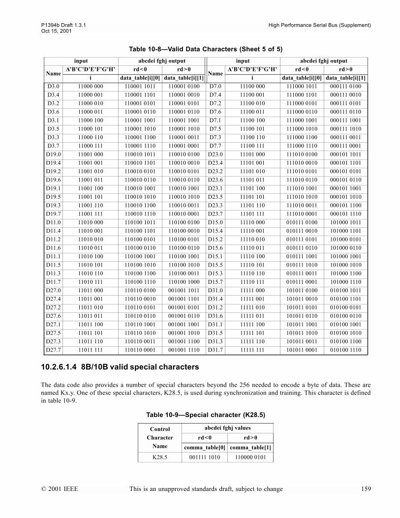
P1394b Draft 1.3.1 High Performance Serial Bus (Supplement)Oct 15, 2001
10.2.6.1.4 8B/10B valid special characters
The data code also provides a number of special characters beyond the 256 needed to encode a byte of data. These arenamed Kx.y. One of these special characters, K28.5, is used during synchronization and training. This character is definedin table 10-9.
D3.0 11000 000 110001 1011 110001 0100 D7.0 11100 000 111000 1011 000111 0100
D3.4 11000 001 110001 1101 110001 0010 D7.4 11100 001 111000 1101 000111 0010
D3.2 11000 010 110001 0101 110001 0101 D7.2 11100 010 111000 0101 000111 0101
D3.6 11000 011 110001 0110 110001 0110 D7.6 11100 011 111000 0110 000111 0110
D3.1 11000 100 110001 1001 110001 1001 D7.1 11100 100 111000 1001 000111 1001
D3.5 11000 101 110001 1010 110001 1010 D7.5 11100 101 111000 1010 000111 1010
D3.3 11000 110 110001 1100 110001 0011 D7.3 11100 110 111000 1100 000111 0011
D3.7 11000 111 110001 1110 110001 0001 D7.7 11100 111 111000 1110 000111 0001
D19.0 11001 000 110010 1011 110010 0100 D23.0 11101 000 111010 0100 000101 1011
D19.4 11001 001 110010 1101 110010 0010 D23.4 11101 001 111010 0010 000101 1101
D19.2 11001 010 110010 0101 110010 0101 D23.2 11101 010 111010 0101 000101 0101
D19.6 11001 011 110010 0110 110010 0110 D23.6 11101 011 111010 0110 000101 0110
D19.1 11001 100 110010 1001 110010 1001 D23.1 11101 100 111010 1001 000101 1001
D19.5 11001 101 110010 1010 110010 1010 D23.5 11101 101 111010 1010 000101 1010
D19.3 11001 110 110010 1100 110010 0011 D23.3 11101 110 111010 0011 000101 1100
D19.7 11001 111 110010 1110 110010 0001 D23.7 11101 111 111010 0001 000101 1110
D11.0 11010 000 110100 1011 110100 0100 D15.0 11110 000 010111 0100 101000 1011
D11.4 11010 001 110100 1101 110100 0010 D15.4 11110 001 010111 0010 101000 1101
D11.2 11010 010 110100 0101 110100 0101 D15.2 11110 010 010111 0101 101000 0101
D11.6 11010 011 110100 0110 110100 0110 D15.6 11110 011 010111 0110 101000 0110
D11.1 11010 100 110100 1001 110100 1001 D15.1 11110 100 010111 1001 101000 1001
D11.5 11010 101 110100 1010 110100 1010 D15.5 11110 101 010111 1010 101000 1010
D11.3 11010 110 110100 1100 110100 0011 D15.3 11110 110 010111 0011 101000 1100
D11.7 11010 111 110100 1110 110100 1000 D15.7 11110 111 010111 0001 101000 1110
D27.0 11011 000 110110 0100 001001 1011 D31.0 11111 000 101011 0100 010100 1011
D27.4 11011 001 110110 0010 001001 1101 D31.4 11111 001 101011 0010 010100 1101
D27.2 11011 010 110110 0101 001001 0101 D31.2 11111 010 101011 0101 010100 0101
D27.6 11011 011 110110 0110 001001 0110 D31.6 11111 011 101011 0110 010100 0110
D27.1 11011 100 110110 1001 001001 1001 D31.1 11111 100 101011 1001 010100 1001
D27.5 11011 101 110110 1010 001001 1010 D31.5 11111 101 101011 1010 010100 1010
D27.3 11011 110 110110 0011 001001 1100 D31.3 11111 110 101011 0011 010100 1100
D27.7 11011 111 110110 0001 001001 1110 D31.7 11111 111 101011 0001 010100 1110
Table 10-9Special character (K28.5)
Control
Character
Name
abcdei fghj values
rd<0 rd>0
comma_table[0] comma_table[1]
K28.5 001111 1010 110000 0101
Table 10-8Valid Data Characters (Sheet 5 of 5)
input abcdei fghj output input abcdei fghj output
NameABCDEFGH rd<0 rd>0
NameABCDEFGH rd<0 rd>0
i data_table[i][0] data_table[i][1] i data_table[i][0] data_table[i][1]
© 2001 IEEE This is an unapproved standards draft, subject to change 159

High Performance Serial Bus (Supplement) P1394b Draft 1.3.1Oct 15, 2001
A comma sequence is singular and occurs with a uniform alignment relative to a character within the code. The K28.5special character contains a sequence that is a comma with respect to the data code. In the absence of errors, the commadoes not occur in any other bit positions, neither within characters nor through overlap between characters. The commasequence for the 8B/10B data code is the seven bit sequence 0011111 or 1100000.
The K28.5 special character is used during the Beta training procedure. While either a training request or an operationrequest is being transmitted, a K28.5 symbol is periodically inserted into the character stream to assist the receiving portin acquiring byte synchronization. Specifically, whenever a training request or operation request is transmitted, the portreplaces each occurrence of a D28.0 character in the transmitted character stream with a K28.5 character. The cyclicnature of the scrambler guarantees a periodic D28.0 character when repeatedly transmitting a particular request.
As the seven bit sequence 0011111 or 1100000 is not a comma for the control code, the occurrence of a K28.5comma character is a necessary but not sufficient condition for byte synchronization (see clause 10.3.2.1.2).
10.2.6.2 Control Coding
In addition to the Dx.y and Kx.y characters, this standard uses a set of characters for coding control symbols. Controlcoding also produces sequences of characters with guaranteed AC transitions and no DC frequency component. The fol-lowing subsections describe the control code features and document the code table.
10.2.6.2.1 Valid Control Code characters
This standard adopts the following definitions and conventions in defining the control code:
Each valid control code character has a name Cz, where z = the 4 bit input value, base 10, for bits PQRS
Table 10-10Control Coding
Control character
name
PQRSabcdeifghj outputs
rd<0 rd>0
i control_table[i]
C0 0000 0000011111
C1 0001 0111110000
C2 0010 0010001111
C3 0011 1110110000
C4 0100 0000111110
C5 0101 0011111000
C6 0110 0100001111
C7 0111 1111010000
C8 1000 0000101111
C9 1001 1011110000
C10 1010 1100000111
C11 1011 1111000001
C12 1100 0001001111
C13 1101 1101110000
C14 1110 1000001111
C15 1111 1111100000
160 This is an unapproved standards draft, subject to change © 2001 IEEE
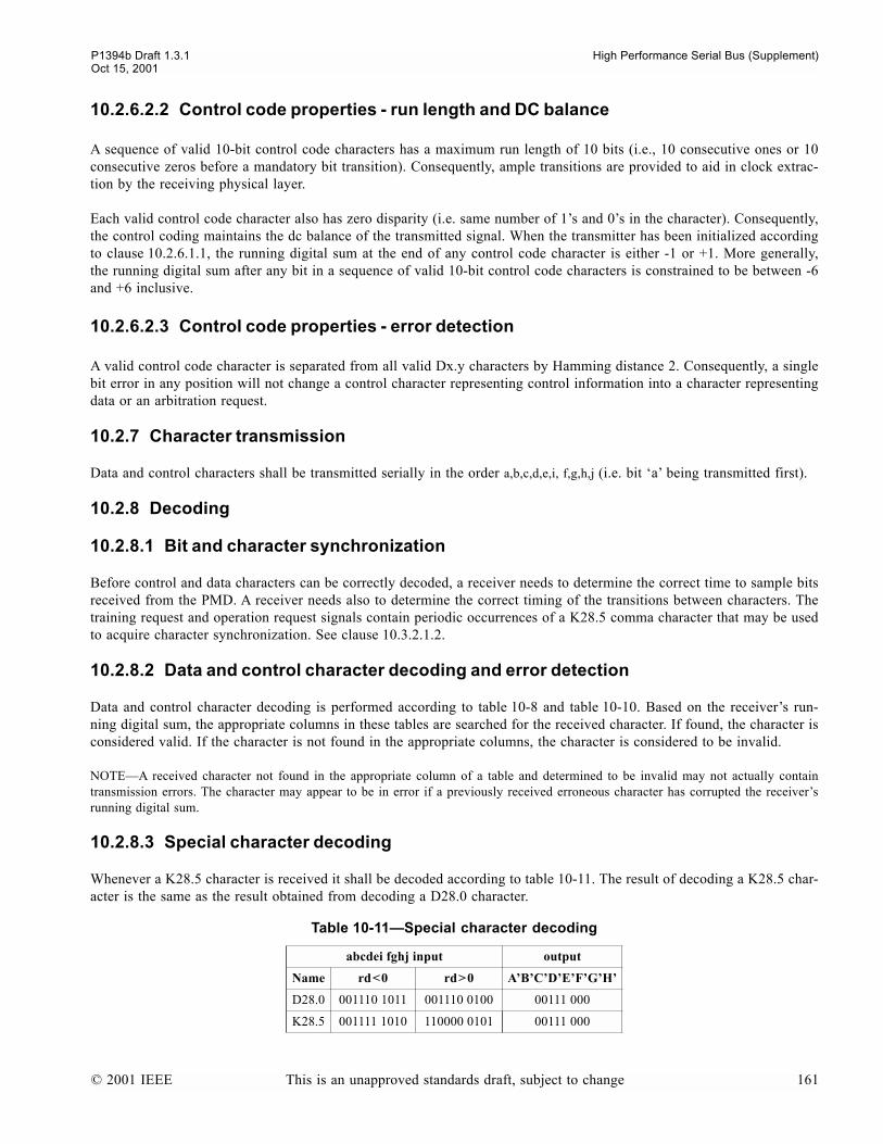
P1394b Draft 1.3.1 High Performance Serial Bus (Supplement)Oct 15, 2001
10.2.6.2.2 Control code properties - run length and DC balance
A sequence of valid 10-bit control code characters has a maximum run length of 10 bits (i.e., 10 consecutive ones or 10consecutive zeros before a mandatory bit transition). Consequently, ample transitions are provided to aid in clock extrac-tion by the receiving physical layer.
Each valid control code character also has zero disparity (i.e. same number of 1s and 0s in the character). Consequently,the control coding maintains the dc balance of the transmitted signal. When the transmitter has been initialized accordingto clause 10.2.6.1.1, the running digital sum at the end of any control code character is either -1 or +1. More generally,the running digital sum after any bit in a sequence of valid 10-bit control code characters is constrained to be between -6and +6 inclusive.
10.2.6.2.3 Control code properties - error detection
A valid control code character is separated from all valid Dx.y characters by Hamming distance 2. Consequently, a singlebit error in any position will not change a control character representing control information into a character representingdata or an arbitration request.
10.2.7 Character transmission
Data and control characters shall be transmitted serially in the order a,b,c,d,e,i, f,g,h,j (i.e. bit a being transmitted first).
10.2.8 Decoding
10.2.8.1 Bit and character synchronization
Before control and data characters can be correctly decoded, a receiver needs to determine the correct time to sample bitsreceived from the PMD. A receiver needs also to determine the correct timing of the transitions between characters. Thetraining request and operation request signals contain periodic occurrences of a K28.5 comma character that may be usedto acquire character synchronization. See clause 10.3.2.1.2.
10.2.8.2 Data and control character decoding and error detection
Data and control character decoding is performed according to table 10-8 and table 10-10. Based on the receivers run-ning digital sum, the appropriate columns in these tables are searched for the received character. If found, the character isconsidered valid. If the character is not found in the appropriate columns, the character is considered to be invalid.
NOTEA received character not found in the appropriate column of a table and determined to be invalid may not actually containtransmission errors. The character may appear to be in error if a previously received erroneous character has corrupted the receiversrunning digital sum.
10.2.8.3 Special character decoding
Whenever a K28.5 character is received it shall be decoded according to table 10-11. The result of decoding a K28.5 char-acter is the same as the result obtained from decoding a D28.0 character.
Table 10-11Special character decoding
abcdei fghj input output
Name rd<0 rd>0 ABCDEFGH
D28.0 001110 1011 001110 0100 00111 000
K28.5 001111 1010 110000 0101 00111 000
© 2001 IEEE This is an unapproved standards draft, subject to change 161
High Performance Serial Bus (Supplement) P1394b Draft 1.3.1Oct 15, 2001
10.2.9 Receiver running disparity
The running disparity is the receivers estimate of the peer ports transmitters running digital sum at the same bit posi-tion. In the absence of transmission errors the receivers running disparity will be the same as the transmitters runningdigital sum. The port shall not update the running disparity when a Cz character is received (note that if the Cz controlcharacter is subsequently decoded and found to be DATA_PREFIX, the running disparity is forced to the value which cor-responds to the encoding used - see 10.3.2.4). Whenever any other character is received, including an invalid characterthat is not found in table 10-8, table 10-9 or table 10-10, the running disparity shall be updated according to the followingrules:
a) The running disparity is updated at the end of each character sub-block, where character sub-blocks are the 6 mostsignificant bits and four least significant bits of the character, i.e. bits a,b,c,d,e,i and bits f,g,h,j.
b) The running disparity is positive at the end of any sub-block if that sub-block contains more 1s than 0s. Therunning disparity is also positive at the end of the 6 bit sub-block 000111 and at the end of the 4 bit sub-block0011.
c) The running disparity is negative at the end of any sub-block if that sub-block contains more 0s than 1s. Therunning disparity is also negative at the end of the 6 bit sub-block 111000 and at the end of the 4 bit sub-block1100.
d) Otherwise the running disparity at the end of any sub-block is the same as at the start of that sub-block.
NOTES
1All sub-blocks with equal number of 1s and 0s leave the running disparity unchanged apart from the particular cases of 6 bit sub-blocks 000111, 111000 and 4 bit sub-blocks 0011, 1100.
2All Cz characters have equal number of 1s and 0s and therefore do not change the running digital sum of the received signal.However, the rules above should not be used to update the running disparity when a Cz character is received.
10.2.10 Descrambling
Control and data symbols shall be descrambled using the reverse of the scrambling procedures as described in 10.2.5. Forsuccessful operation, the state of a receivers descrambler should be synchronized with the state of the scrambler in theremote ports transmitter. This requires that the receiver learn the state of the remote transmitters scrambler during porttraining. A receiver shall synchronize the state of its descrambler with the state of the remote transmitters scramblerwhile receiving sequences of valid TRAINING or OPERATION configuration request symbols.
NOTEA receiver may train its scrambler by using the fact that the least significant bit of all Configuration Requests (in particularTRAINING and OPERATION Configuration Requests) is zero, thus when the transmitter is transmitting Configuration Requests theleast significant bit of the scrambled symbol before 8B10B encoding will be the same as the least significant bit of the scrambler. Thiswill be preserved through 8B10Bencoding, serial transmission and 10B8B decoding in the receiver (provided that there is no polarityinversion). Hence the least significant bit of the received symbol after 10B8B decoding will be the same value as the least significantbit of the state of the transmitters scrambler at the time the Configuration Request was scrambled. The design of the scrambler is suchthat forcing the least significant bit of the receivers scrambler to the value learned in this way results in scrambler synchronizationwithin 11 symbols.
10.3 Beta mode port operation
10.3.1 Transmit operations
10.3.1.1 Control transmission
When requested to transmit a control token, the port may need to stretch its duration to ensure that when the control tokenis subsequently forwarded through ports operating at a lower speed, those ports have sufficient time to transmit at leastone control character. Stretching the duration is performed by transmitting the corresponding control character repeatedly.
162 This is an unapproved standards draft, subject to change © 2001 IEEE

P1394b Draft 1.3.1 High Performance Serial Bus (Supplement)Oct 15, 2001
It is controlled by an effective speed parameter that is passed to the port along with the control token. The number ofcharacters transmitted for each control token is equal to the ratio of the port operating speed and this speed parameter, asshown in table 10-12.
NOTEFor any particular effective speed, a stretched sequence has constant duration at all port speeds, equal to the time taken totransmit a single character on a port operating at the effective speed.
NOTEC represents a control character.
For each control character that is transmitted, the Beta port shall first determine the control symbol for that control tokenaccording to table 10-1. This control symbol shall be scrambled according to clause 10.2.5.3 and coded according toclause 10.2.6.2 and the resulting control character shall be transmitted according to clause 10.2.7.
10.3.1.2 Request transmission
For each Beta port request the port shall first determine the request symbol according to table 10-2, table 10-3 andtable 10-5. This symbol shall be scrambled according to clause 10.2.5.2, coded according to clause 10.2.6.1 and the result-ing data characters shall be transmitted according to clause 10.2.7.
Whenever the port is transmitting either a TRAINING or OPERATION configuration request signal, and the data charac-ter to be transmitted is a D28.0 character, the port shall replace this character with a K28.5 special character.
NOTEThe insertion of K28.5 characters assists a remote receiver in establishing character synchronization with the transmitting port.
At least four consecutive request symbols shall be transmitted for any given Configuration Request, as an aid to robust-ness.
Table 10-12Control stretching formats
Port operating speedeffective speedS100 S200 S400 S800 S1600 S3200
S100 CS200 CC CS400 CCCC CC CS800 CCCCCCCC CCCC CC CS1600 CCCCCCCCCCCCCCCC CCCCCCCC CCCC CC CS3200 CCCCCCCCCCCCCCCCCCCCCCCCCCCCCCCC CCCCCCCCCCCCCCCC CCCCCCCC CCCC CC C
© 2001 IEEE This is an unapproved standards draft, subject to change 163

High Performance Serial Bus (Supplement) P1394b Draft 1.3.1Oct 15, 2001
10.3.1.3 Packet transmission
A packet may be preceded by a number of DATA_PREFIX control tokens. Packet transmission begins with either a speedcode or, in the case of some S100 packets where there is no speed code, the first data byte. During packet transmissionthe port may still be required to transmit some control tokens, for example to complete a packet prefix. These controltokens and the packet data are referred to collectively as the packet payload. When the packet speed is less than the portoperating speed, other characters are transmitted during the packet along with the payload characters. These characters arereferred to as padding characters. This process is illustrated in figure 10-7.
In contrast to Legacy DS ports, the port transmission speed remains constant for all packet speeds.
Figure 10-7Structure of packet, packet delimiters and request types, with examples of coding process.
speed data prefix data packet endsymbols
packet prefix packet packet end
signaldata prefix
payload
padding
payload
Dx.y Cz Cz Cz Dx.y
character character
character
control token = DATA_PREFIX
Control Symbol = 1010
Scrambled Control Symbol = 0101
Control Character = 0011111000
(assume scrambler state = 1111 1111)
(assume rd < 0)
Asynchronous Request = NONE_ODD
Request Symbol = 10010xx0
Scrambled Request Symbol = 01101xx1
Data Character = 0110101101
(assume scrambler state = 1111 1111)
Isochronous Request = ISOCH_EVEN
Scrambled Request Symbol = 01101001(D22.4 after forcing bits F & G to 0)
(assuming rd < 0)
164 This is an unapproved standards draft, subject to change © 2001 IEEE

P1394b Draft 1.3.1 High Performance Serial Bus (Supplement)Oct 15, 2001
10.3.1.4 Speed signaling
A speed code comprises a sequence of SPEEDa, SPEEDb and SPEEDc control tokens and is transmitted during thepacket prefix. The combination of SPEEDa, SPEEDb and SPEEDc control tokens transmitted indicates the packet speedrelative to the port operating speed. In addition the use of a SPEEDa or SPEEDb token indicates that the packet format isLegacy or Beta respectively (see clause 13.3.1.1). When required to transmit a speed code, the port shall generate asequence of speed control tokens appropriate for the packet speed according to table 10-13. Each speed control tokenshall be coded according to clause 10.2.6.2 and scrambled according to clause 10.2.5.3 .
Sc represents the SPEEDc control token.
Sx represents the SPEEDa control token when the Legacy packet format is used, and represents the SPEEDbcontrol token when the Beta packet format is used.
For any particular packet speed, the speed signal has constant duration at all port speeds. At all packet speeds the numberof speed tokens used at a particular port operating speed is equal to the number of symbols transmitted per byte of packetdata at that port operating speed.
NOTEa speed code is not transmitted for a Legacy format S100 packet originated by a border node with a Legacy link or for aforwarded packet where the received packet has no speed code. See clause 13.3.1.4.
10.3.1.5 Payload transmission
If the packet speed is less than the port operating speed then data payload is padded with SPEEDc symbols. Each databyte shall be scrambled according to clause 10.2.5.1 and the scrambled data shall be coded according to clause 10.2.6.1.The resulting character shall be transmitted immediately before any SPEEDc control symbols. The port compares thevalue of the packet speed parameter with the port operating speed and determines the number of SPEEDc control symbolsto be transmitted according to table 10-14. The port shall generate the appropriate number of SPEEDc control symbols.These shall be scrambled according to clause 10.2.5.3 and coded according to clause 10.2.6.2, and the resulting controlcharacters shall be transmitted contiguously following the data character.
Table 10-13Speed Code Formats
Port operating speedPacket speedS100 S200 S400 S800 S1600 S3200
S100 Sx
S200 ScSx Sx
S400 ScScSxSc ScSx Sx
S800 ScScScSxScScScSc ScScSxSc ScSx Sb
S1600 ScScScScSxScScScScScScScScScScSc ScScScSxScScScSc ScScSxSc ScSb Sb
S3200 ScScScScScSxScScScScScScScScScScScScScScScScScScScScScScScScScSc
ScScScScSxScScScScScScScScScScSc
ScScScSxScScScSc ScScSbSc ScSb Sb
speed signal duration (nsecs)
80 40 20 10 5 2.5
Table 10-14Data padding formats
Port operating speed
Packet speedS100 S200 S400 S800 S1600 S3200
S100 DS200 DP DS400 DPPP DP DS800 DPPPPPPP DPPP DP DS1600 DPPPPPPPPPPPPPPP DPPPPPPP DPPP DP DS3200 DPPPPPPPPPPPPPPPPPPPPPPPPPPPPPPP DPPPPPPPPPPPPPPP DPPPPPPP DPPP DP D
© 2001 IEEE This is an unapproved standards draft, subject to change 165
High Performance Serial Bus (Supplement) P1394b Draft 1.3.1Oct 15, 2001
NOTES
1For any particular packet speed, a padded sequence has constant duration at all port speeds.
2D represents a payload data byte.
3P represents a SPEEDc control symbol.
4Table entries represent the information stream prior to scrambling and coding.
If the packet speed is less than the port speed then any payload control symbols are stretched as described inclause 10.3.1.1.
10.3.2 Receive operations
10.3.2.1 Port training
When a Beta mode port is initially activated, the port shall initiate a training procedure. During this procedure, the porttransmits a sequence of training symbols to the remote port. The remote port also begins the training procedure, and trans-mits a sequence of training symbols. While receiving a training sequence, the port synchronizes itself with the receivedcharacter stream. The port acquires bit synchronization and also determines the boundary between characters (charactersynchronization). The port also synchronizes its descrambler with the scrambler of the peer ports transmitter.
10.3.2.1.1 Loss of synchronization detection procedure
The port determines that it has lost synchronization with the received character stream by monitoring the validity ofreceived characters. The port shall maintain a count of the number of invalid characters received. Whenever an invalidcharacter is received, this count shall be incremented, to a maximum value of four. Whenever two consecutive valid char-acters are received, the count shall be decremented (to a minimum value of zero). If the count reaches four then the portshall give a loss of synchronization indication.
For the purposes of loss of synchronization detection, an invalid character shall be any character that does not appear inthe appropriate disparity column of table 10-8, table 10-9 or table 10-10. In addition, whilst in the Receive state (i.e.during normal operation) the port receiver shall consider the TRAINING configuration request to be an invalid signal.This provides a means for a remote port to force the receiving port to enter the synchronization procedure.
10.3.2.1.2 Resynchronization procedure
When the port is initially activated and whenever the port determines that synchronization has been lost, it shall transmita TRAINING configuration request and attempt to resynchronize with the incoming character stream. The TRAININGconfiguration request is treated in the same way as an INVALID symbol by the remote port, and therefore causes theremote port to enter the synchronization procedure.
The port shall initially attempt to acquire character synchronization. In order to verify that character synchronization iscomplete, the port shall receive a valid comma character (i.e. a K28.5 special character) preceded by at least two validrequest type characters (Dx.0 or Dx.4).
NOTEWhen a port first begins resynchronization, it may not necessarily be receiving training signals from the remote port. Therequirement for a K28.5 to be preceded by two valid request type characters is necessary to ensure that incorrect charactersynchronization cannot occur when signals other than the TRAINING or OPERATION configuration requests are received.
Once character synchronization is complete, the port shall train its descrambler. The port shall verify that descramblertraining has been successful by checking for at least SYNC_CHECK consecutive occurrences of a TRAINING configura-tion request or SYNC_CHECK consecutive occurrences of a OPERATION configuration request. SYNC_CHECK hasvalue 17.
166 This is an unapproved standards draft, subject to change © 2001 IEEE

P1394b Draft 1.3.1 High Performance Serial Bus (Supplement)Oct 15, 2001
If during this check an arbitration request type is received that indicates an isochronous request type of ISOCH_ODD andan asynchronous request type of reserved with the value 111 (11111xx0), or if an arbitration request type is received thatindicates an isochronous request type of ISOCH_ODD and an asynchronous request type of NONE_ODD (10011xx0),then a polarity inversion between the two sides of the differential signal may have occurred in the cable plant, and theport shall subsequently invert all received characters and restart this check.
NOTEIt is not necessary for the port to repeat the character synchronization and descrambler training if the polarity is found to beinverted.
Upon achieving synchronization, the port shall begin to transmit an OPERATION configuration request. The port shallcontinue to transmit OPERATION configuration requests until it has received and successfully decoded at least2*SYNC_CHECK consecutive OPERATION configuration requests since the beginning of sending an OPERATION con-figuration request, or has received a control symbol, or is deactivated by the connection management function.
10.3.2.2 Control reception
When any valid control character is received, the port shall determine the received control symbol by decoding the con-trol character according to clause 10.2.8 and descrambling the result of the decoding operation according toclause 10.2.10. In order to be a valid control character, a received character shall appear in table 10-10.
When control symbols are received within a packet prefix (i.e. DATA_PREFIX symbols between the speed signal and thepacket data) the port shall determine the stretching format of the control symbols from the packet speed and port operat-ing speed according to table 10-12. For the first control character in each stretched sequence the port shall determine thereceived control token according to table 10-1 and indicate this to the arbitration state machine. Other control symbols inthe stretched sequence shall not be indicated to the arbitration state machine (i.e. the port shall only indicate the controlsymbol received in the payload position).
When control symbols are received at the packet end or outside of a packet, the port shall determine the received controltoken according to table 10-1. When a change on the received control token is detected (including the beginning of con-trol token reception) the port shall indicate the first occurrence of the new control token to the arbitration state machine.The port shall not indicate subsequent contiguous occurrences of the same control token to the arbitration state machine.
NOTEThis requirement is intended to ensure that isolated occurrences of a control token are never deleted by the port, whileallowing redundant control symbols to be deleted when necessary to compensate for any difference between the local port clock andremote port clock frequencies.
If an invalid character is received during control token reception the port shall maintain the previous control token indi-cation.
10.3.2.3 Request type reception
Characters representing request types shall be distinguished from those representing packet data by the fact that they arereceived outside of packet boundaries. In order to be a valid request character, a received character shall belong to the setof Dx.0 and Dx.4 characters (x=0,1,...31) and appear in the appropriate column of table 10-8 as determined by the runningdisparity at the start of reception of the character. The port shall decode all valid request characters according toclause 10.2.8 and descramble the result of the decoding operation according to clause 10.2.10. The request type shall bedetermined from table 10-2, table 10-3 and table 10-5.
Any difference between the frequencies of the remote port clock and local port clock will result in the local port occasion-ally needing to either insert or delete request indications. When a request type is inserted it shall be equal to the previ-ously indicated request type.
© 2001 IEEE This is an unapproved standards draft, subject to change 167

High Performance Serial Bus (Supplement) P1394b Draft 1.3.1Oct 15, 2001
A Configuration Request shall only be recognized if two consecutive identical Configuration Request symbols arereceived (note that at least four consecutive identical symbols will have been transmitted). This provides protectionagainst bit errors that may cause an arbitration request to be converted to a configuration request. If an invalid characteris received during request type reception, the port shall maintain the previous request type indication.
10.3.2.4 DATA_PREFIX reception
All packets received by a port are preceded by a number of DATA_PREFIX symbols. The DATA_PREFIX symbol indi-cates the state of the remote source ports running digital sum at the start of the packet. Since the receiving port isrequired to check the running disparity during packet reception, it is necessary for the receiving port to have correctknowledge of the running digital sum at the start of a packet. The running disparity should be updated at the start of eachreceived packet as information held over from previously received characters may be incorrect due to errors in thereceived signals.
Whenever a DATA_PREFIX symbol is received, the port shall update the running disparity value to the value indicatedby the DATA_PREFIX symbol.
10.3.2.5 Speed code determination
A Beta mode port shall receive a speed code (if any) and indicate the speed of the subsequent packet to the arbitrationstate machine. This indication shall not be generated before a SPEEDa or SPEEDb token or a data byte has been received.Valid speed signals shall be used to determine the speed of the subsequent packet according to table 10-15.
Sc represents the SPEEDc control token.
Sx represents either a SPEEDa or a SPEEDb token.
A speed code shall only be considered valid if it meets the following criteria:
a) All speed tokens are received consecutively.b) The pattern of SPEEDc and SPEEDx (x = a or b) tokens is found in table 10-15.
If an invalid speed code is detected the port shall pass the packet to the arbitration state machine as a Legacy format S100packet in a hybrid bus and a Beta format S100 packet in a B-bus. However, if an invalid speed code is detected during theself_ID phase, the PHY shall initiate a new bus reset.
10.3.2.6 Payload reception
All characters, whether control or data, received following a speed code or the first byte of data are considered part of thepacket, until the packet end is received. The packet speed may be used to determine the padding format of the packet. Theport shall consider the first character received in a padded sequence to be the payload character. During packet receptionthe port shall discard all padding characters and only indicate payload characters to the arbitration state machine.
Table 10-15Speed code decoding
Received speed codePort operating speed
S100 S200 S400 S800 S1600 S3200none S100 S100 S100 S100 S100 S100Sx S100 S200 S400 S800 S1600 S3200ScSx - S100 S200 S400 S800 S1600ScScSxSc - S100 S200 S400 S800ScScScSxScScScSc - S100 S200 S400ScScScScSxScScScScScScScScScScSc - S100 S200ScScScScScSxScScScScScScScScScScScScSc-ScScScScScScScScScScScScSc
S100
168 This is an unapproved standards draft, subject to change © 2001 IEEE
P1394b Draft 1.3.1 High Performance Serial Bus (Supplement)Oct 15, 2001
During packet reception the port shall determine whether a received payload character is a valid data character or a validcontrol character. In order to be a valid data character, a received character shall appear in the appropriate column oftable 10-8 as determined by the running disparity at the start of reception of the character. In order to be a valid controlcharacter, a received character shall appear in table 10-10.
The port shall decode all valid data payload characters according to clause 10.2.8 and descramble the result of the decod-ing operation according to clause 10.2.10.
If a valid control payload character is received, the port shall determine the received control token by decoding the con-trol character according to clause 10.2.8 and descrambling the result of the decoding operation according toclause 10.2.10. The port shall consider the first control character in a padded sequence to be the payload character. Theport shall determine the format of the padded sequence for the packet speed according to table 10-12.
The port shall check that the format of the packet data sequence (padded or not) agrees with that indicated by table 10-14for the packet speed. If no speed signal is received prior to the packet, then the packet speed should be S100, and the portshall check that the padding format is correct for an S100 packet. If at any point during packet reception a valid data char-acter is received at a time when the padding format for the packet speed requires a padding symbol to be received, thenan error has occurred and the port shall not report that data to the arbitration state machine. If during packet reception theport receives a payload character that is neither a valid data character nor a valid control character, it shall indicate to thearbitration state machine that a data byte of value [0000 0000] was received.
NOTEA data character is only considered as being in error if the invalid character is in a payload position. Errors in paddingpositions are ignored.
Data reception ends when a packet end symbol is received.
10.3.2.7 Error reporting
Whenever the port detects a coding error, it shall increment the value of the port_error register, to a maximum value of255. The port_error register shall be an 8 bit read-only PHY register. This register is intended for use by a single bus widediagnostic program, and shall be cleared when read. The port takes no action based on the value of this register. A codingerror shall be detected if a character is received which:
a) does not belong to the set of data characters nor the set of control characters, orb) has incorrect disparity, orc) is a valid data character, but not Dx.0 or Dx.4, and occurs outside the bounds of a packet, ord) is a valid payload character but is not received in the correct payload position within a padded packet, ore) is a valid padding character but is not received in a correct padding position within a padded packet.
10.4 Beta mode port state machines
The operation of the port operating in Beta mode is specified in terms of a transmit state machine and a receive statemachine, together with C code specifying the actions to be taken on entry to each state. The C code variables used in theBeta mode port state machines are described in Table 10-16 .
Table 10-16C code variables used in Beta mode port state machines (Sheet 1 of 2)
Function or variable name Description
bport_on Set to true to instruct the Beta port to commence operating, set to false to instruct the Beta port to cease operating
bport_sync_ok port has achieved synchronization with peer port
power_reset TRUE during power reset, goes false at the end of power reset
rx_sync_error TRUE if receiver failed to complete synchronization
© 2001 IEEE This is an unapproved standards draft, subject to change 169

High Performance Serial Bus (Supplement) P1394b Draft 1.3.1Oct 15, 2001
10.4.1 Port transmit state machine
NOTEall C-code function names listed here are hypertext links in electronic versions of this specification
10.4.1.1 Port transmit state machine notes
State PTX0:Off. The port is not transmitting.
Transition PTX0:PTX1. The Beta mode port is activated by the connection management function setting bport_on to betrue. The first action after being activated is for the port to attempt to synchronize with the connected port.
State PTX1: Sync lost. While in this state the port transmits a training request signal to the connected port.
Transition PTX1:PTX2. This transition is made when the receiver signals that it has acquired synchronization with theconnected port.
scrambler_sync SYNC_CHECK consecutive occurrences of TRAINING or OPERATION received
scrambler_sync_error TRUE if unexpected request type is received during scrambler synchronization
sync_error_signal receiver error monitor has detected loss of synchronization
sync_lost_signal receiver is in a resynchronization state
Figure 10-8Port transmit state machine
Table 10-16C code variables used in Beta mode port state machines (Sheet 2 of 2)
Function or variable name Description
PTX3:Transmitbport_transmit_actions();
bport_sync_ok
PTX1:Sync Losttx_sync_lost_actions();
!sync_lost_signal
PTX2:Local Synctx_sync_actions();
sync_lost_signal
PTX0:Offtx_off_actions()
bport_on
!bport_on
PTX2:PTX3
PTX2:PTX1
PTX1:PTX2
PTX1:PTX0
PTX0:PTX1
power_reset
!bport_onPTX2:PTX0
!bport_on || sync_lost_signalPTX3:PTX0
170 This is an unapproved standards draft, subject to change © 2001 IEEE
P1394b Draft 1.3.1 High Performance Serial Bus (Supplement)Oct 15, 2001
Transition PTX1:PTX0. If the connection management function sets bport_on false, then the port returns to the Offstate. This may happen if the connection management function decides that training has failed by timing out.
State PTX2: Local Sync. The port receiver is synchronized with the connected port, and the port transmits an operationrequest signal to indicate that it wishes to commence normal operation.
Transition PTX2:PTX0. The connection management function may still cause the port to transition to the Off state fromthe Local Sync state by setting bport_on false.
Transition PTX2:PTX1. If the port receiver signals that it has lost synchronization with the connected port, the transmit-ter returns to the Sync Lost state.
Transition PTX2:PTX3. However, if the port receiver determines that the connected port has also acquired synchroniza-tion, then the transmitter transition to the Transmit state.
State PTX3: Transmit. This is the normal operating state for the transmitter.
Transition PTX3:PTX0. The port returns to the Off state if synchronization is lost or if the connection managementfunction sets bport_on false.
© 2001 IEEE This is an unapproved standards draft, subject to change 171

High Performance Serial Bus (Supplement) P1394b Draft 1.3.1Oct 15, 2001
10.4.2 Port receive state machine
NOTEall C-code function names listed here are hypertext links in electronic versions of this specification
10.4.2.1 Port receive state machine notes
State PRX0: Off. The port is not required to receive or decode any signals.The sync_lost_signal is set in this state to forcethe transmit port into PTX0.
Transition PRX0:PRX1. When the connection management function sets bport_on true, the port shall enter the Resync1state and attempt to acquire bit and character synchronization.
State PRX1: Resync1. While in this state the receiver is attempting to acquire bit and character synchronization. Thereceiver also requests that the transmitter sends a TRAINING request signal.
Transition PRX1:PRX0. If the connection management function sets bport_on false, then the port returns to the Off state.
Transition PRX1:PRX2. Character synchronization is considered complete when a comma character (K28.5) has beenreceived, immediately preceded by at least two consecutive valid request type characters (Dx.0 or Dx.4).
Figure 10-9Port receive state machine
PRX4:Receivebport_receive_actions();
!sync_error_signal
PRX1:Resync1rx_sync_lost_actions();
scrambler_sync
PRX3:Local Syncrx_sync_actions();
rx_sync_error
PRX0:Offrx_off_actions()
bport_on
!bport_on
bport_on
PRX2: Resync2scrambler_sync_actions();
scrambler_sync_error
PRX1:PRX0
power_reset
PRX0:PRX1
PRX1:PRX2
PRX2:PRX3
PRX2:PRX1
PRX3:PRX1
PRX3:PRX4
!bport_onPRX2:PRX0
!bport_onPRX3:PRX0
!bport_on || sync_error_signalPRX4:PRX0
172 This is an unapproved standards draft, subject to change © 2001 IEEE
P1394b Draft 1.3.1 High Performance Serial Bus (Supplement)Oct 15, 2001
State PRX2: Resync2. In this state the receiver trains its descrambler using the scrambler samples contained in the incom-ing character stream.
Transition PRX2:PRX0. If the connection management function sets bport_on false, then the port returns to the Off state.
Transition PRX2:PRX1. If any invalid character is received, the receiver returns to the start of the synchronization poce-dure.
Transition PRX2:PRX3. After the descrambler is trained and least SYNC_CHECK consecutive training or operationrequests have been received, the receiver is synchronized.
State PRX3: Local Sync. Once it is synchronized, the receiver requests that the transmitter sends a OPERATION requestsignal and waits for the attached port to indicate that it also is synchronized.
Transition PRX3:PRX0. If the connection management function sets bport_on false, then the port returns to the Off state.
Transition PRX3:PRX1. If any invalid character, or any unexpected signal is received then the receiver returns to the startof the synchronization procedure.
Transition PRX3:PRX4. Once the receiver has received an operation request from the attached transmitter, it beginsnormal operation.
State PRX4: Receiver. This is the normal operating state.
Transition PRX4:PRX0. If the connection management function sets bport_on false, or if the receiver loses synchroniza-tion, then the port returns to the Off state.
© 2001 IEEE This is an unapproved standards draft, subject to change 173

High Performance Serial Bus (Supplement) P1394b Draft 1.3.1Oct 15, 2001
174 This is an unapproved standards draft, subject to change © 2001 IEEE

P1394b Draft 1.3.1 High Performance Serial Bus (Supplement)Oct 15, 2001
11. Connection Management
11.1 Overview
Connection management is performed by a node-level connection monitor for the physical layer and a Port ConnectionManager for each port, together with the communications used between these modules, and the services provided by thesemodules.
The relationship and interfaces between Connection Management and other functions and layers are illustrated infigure 11-1:
Each Connection Manager interacts with the corresponding physical media dependent layers, the Beta mode port func-tions, the DS mode functions and the repeater functions by appropriate shared variables.
Figure 11-1PHY master architecture (Data routing, arbitration and control interfaces in context)
BOSS arbitration and control state machines.
Cat. 5 UTP - or -Glass optical fiber -or-
Plastic optical fiber -or -Beta-only electrical -or-Bilingual electrical -or -
DS-only electrical
Link
B PHY
PHY-Link interface
packet transmit/receive
port controller
DS mode functions
Beta mode
functions
Connection management
Low power signaling
Port
to other ports
pa
cke
t d
ata
send LTP PHY packets
req
ue
st\
gra
nt
packet control
request/grant, enable LTP RX flags
TX/RX symbol,port status
TX/RX symbol
TX/RX symbol,enables
con
tro
l
con
figco
ntr
ol
po
rtst
atu
s
PMD Cat. 5 UTP - or -Glass optical fiber -or-
Plastic optical fiber -or -Beta-only electrical -or-Bilingual electrical -or -
DS-only electrical
PMD
DS mode functions
Beta mode
functions
Connection management
Low power signaling
Port
PHY packets
TX/RX data signals, PMD control/status,arb/connect control/status (DS only)
TX/RX data signals, PMD control/status,arb/connect control/status (DS only)
© 2001 IEEE This is an unapproved standards draft, subject to change 175
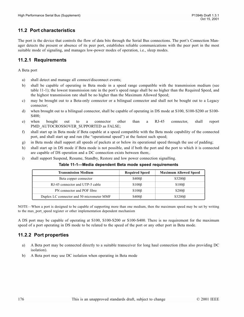
High Performance Serial Bus (Supplement) P1394b Draft 1.3.1Oct 15, 2001
11.2 Port characteristics
The port is the device that controls the flow of data bits through the Serial Bus connections. The ports Connection Man-ager detects the present or absence of its peer port, establishes reliable communications with the peer port in the mostsuitable mode of signaling, and manages low-power modes of operation, i.e., sleep modes.
11.2.1 Requirements
A Beta port
a) shall detect and manage all connect/disconnect events;b) shall be capable of operating in Beta mode in a speed range compatible with the transmission medium (see
table 11-1); the lowest transmission rate in the ports speed range shall be no higher than the Required Speed, andthe highest transmission rate shall be no higher than the Maximum Allowed Speed;
c) may be brought out to a Beta-only connector or a bilingual connector and shall not be bought out to a Legacyconnector;
d) when brought out to a bilingual connector, shall be capable of operating in DS mode at S100, S100-S200 or S100-S400;
e) when bought out to a connector other than a RJ-45 connector, shall reportPMD_AUTOCROSSOVER_SUPPORTED as FALSE;
f) shall start up in Beta mode if Beta capable at a speed compatible with the Beta mode capability of the connectedport, and shall start up and run (the operational speed) at the fastest such speed;
g) in Beta mode shall support all speeds of packets at or below its operational speed through the use of padding;h) shall start up in DS mode if Beta mode is not possible, and if both the port and the port to which it is connected
are capable of DS operation and a DC connection exists between them;.i) shall support Suspend, Resume, Standby, Restore and low power connection signalling.
NOTEWhen a port is designed to be capable of supporting more than one medium, then the maximum speed may be set by writingto the max_port_speed register or other implementation dependent mechanism
A DS port may be capable of operating at S100, S100-S200 or S100-S400. There is no requirement for the maximumspeed of a port operating in DS mode to be related to the speed of the port or any other port in Beta mode.
11.2.2 Port properties
a) A Beta port may be connected directly to a suitable transceiver for long haul connection (thus also providing DCisolation).
b) A Beta port may use DC isolation when operating in Beta mode
Table 11-1Media dependent Beta mode speed requirements
Transmission Medium Required Speed Maximum Allowed Speed
Beta copper connector S400β S3200β
RJ-45 connector and UTP-5 cable S100β S100β
PN connector and POF fibre S100β S200β
Duplex LC connector and 50 micrometer MMF S400β S3200β
176 This is an unapproved standards draft, subject to change © 2001 IEEE

P1394b Draft 1.3.1 High Performance Serial Bus (Supplement)Oct 15, 2001
11.3 Functions, variables and constants
Connection management is specified as a port connection manager state machine for each port, and a number of continu-ously running C code machines, some of which operate at node level. The C code functions and variables used in the portconnection manager state machine are described in table 11-2.
Table 11-2Port connection manager state machine variables and functions
Variable Description
active Indicates that the port is in state P2:Active (set by state machine transitions to/from P2)
Beta_mode Set if the port has determined that it is operating in Beta mode, unset otherwise (i.e. when oper-ating in DS-Mode, or when in P0:disconnected). This is maintained as a read-only bit in the port register map.
bport_sync_ok Variable shared with the Beta mode port. Indicates that the port has byte and scrambler synchro-nization with its peer
connected Connection established with a peer port, and (Beta mode only) operating speed negotiation com-pleted. This is maintained as a read-only bit in the port register map.
connection_unreliable PHY register bit, set true if the Beta mode speed negotiation fails or synchronization fails whilst establishing the operating mode and speed of a connection. Reset by software after appropriate higher level action has been taken.
disable_request Requests transmission of DISABLE_NOTIFY at the end of the next packet
disabled PHY register bit, set to disable a port under software control, and indicates that the port is in state P6:Disabled
do_standby TRUE when the port has been commanded to be a standby initiator
force_disconnect TRUE to force disconnect and retest of a port after detecting a loop during reset
in_standby Port is in State P7:Standby Initiator, P8:Standby Target, P9:Standby or P10:Restore
loop_disabled Port is in State P12: Loop_disabled
loop_to_detect TRUE during reset up to arb state S1 or S2
receive_ok In DS mode indicates the reception of a debounced TpBias signal
In Beta mode, indicates the reception of a continuous electrically valid signal. Note, is set to false during the time that only connection tones are detected in Beta mode.
This is maintained as a read-only bit in the port register map (supersedes the Bias bit in IEEE Std 1394a-2000).
restore Indicates that the port is restoring, also causes a port in standby to restore.
resume Indicates that the port is resuming, also causes a suspended port to resume.
resume_fault Set when peer port fails to complete resume
rx_disabled Indicates reception of DISABLE_NOTIFY token from peer port
rx_standby Indicates reception of STANDBY token from peer port
rx_suspend Indicates reception of SUSPEND token from peer port
signaled Indicates transmission of DISABLE_NOTIFY, SUSPEND or STANDBY
standby_fault Set when peer port fails to complete standby
suspend_request Requests transmission of SUSPEND at the end of the next packet and/or indicates that the port is suspending
suspend_fault Set when peer port fails to complete suspend
untested port is connected but untested
untested_state port is in state P11:Untested
© 2001 IEEE This is an unapproved standards draft, subject to change 177

High Performance Serial Bus (Supplement) P1394b Draft 1.3.1Oct 15, 2001
The timing constants and related parameters used in the Connection Management descriptions are defined in table 11-3.
Note: The values of TEST_INTERVAL and COLLISION_LIMIT are chosen to insure that the loop testing will completemuch more than a TEST_INTERVAL before the MAX_OCCUPANCY_TIME timer expires. This insures that the finalLTP with ATTACH_IN_PROGRESS is seen by all controlling nodes on other buses before an attach is completed.
Table 11-3Connection Management Constants
Timing constant Minimum Maximum Comment
BIAS_FILTER_TIME 41.6 µs 52.1 µs Time on a DS capable port to filter bias_detect upon the detec-tion of TpBias before updating the PHY register Receive_OK bit (~4096/BASE_RATE)
COLLISION_LIMIT 7 Number of times a collision condition occurs to conclude that a loop exists
CONNECT_TIMEOUT 330 ms 350 ms Connection debounce time
DISCONNECTED_TONE_INTERVAL 42.66ms 48 ms TONE_DURATION * 4 * TONE_INTERVAL
(2**22/BASE_RATE)
MAX_OCCUPANCY_TIME 83.975µs 83.993µs The duration of the max occupancy timer (the maximum time that the bus is held while performing loop free build to allow a peer conection to issue a short bus reset) (~8256/BASE_RATE)
NUM_OF_TRIES 4 Number of tries at toning before switching to trying TpBias
PORT_ENABLE_TIME 1 ms Time necessary for TpBias output to become valid when driven high. The minimum value is implementation-dependent and may incorporate other design timing requirements for port resump-tion.
RECEIVE_OK_HANDSHAKE 5.3 ms 16 ms When used to detect a fault during a suspend or resume hand-shake on a port operating in DS mode, this is either the time a suspend initiator waits for the suspend target to remove bias (measured from the transmission of TX_SUSPEND) before a suspend fault exists or the time a resume initiator waits for the resume target to assert bias (measured from the generation of TpBias by the resume initiator) before a resume fault exists.
Also the time a suspend target waits, measured from the time it drives TpBias low, before it suspends.
Ports operating in Beta mode may also use this timing value instead of values based on Beta mode synchronization time.
RECEIVER_INIT_TIME 1ms Time from first receipt of signal for a receiver to be operating within the BER objective of 10-12
RESET_DETECT 80.0ms 85.3ms Time for an active port to confirm a reset signal
RESUME_CHECKS 65 DISCONNECTED_TONE_INTERVAL/TONE_DURATION
+ 1, the number of checks that are made between connection tone intervals
SPEEDCODE_BIT_INTERVAL 1.9998ms 2.0002ms TONE_DURATION * 3, the time between the end of one tone position and the start of the next
SYNCHRONIZATION_LENGTH 16384 (maximum number of transmitted bits for scrambler synchroni-zation + byte synchronization rounded up to a power of two)
TEST_INTERVAL 7.811µs 7.814µs Time to allow a test value to be returned as a LTS (~768/BASE_RATE)
TONE_DURATION 666.6µs 666.7µs 2**16/BASE_RATE
TONE_GAP 8 TONE_INTERVAL / 2, he number of tone units in the gap before the start bit
TONE_INTERVAL 16 The number of tone units in a tone interval
178 This is an unapproved standards draft, subject to change © 2001 IEEE

P1394b Draft 1.3.1 High Performance Serial Bus (Supplement)Oct 15, 2001
11.4 Port controller
There shall be one instantiation of the port controller in a PHY. Its behavior is specified as continuously running C code,and maintains a record of whether the node is an isolated or boundary node. It also contains routines called by the indi-vidual port connection managers providing a global view of the connection information for the other ports. Finally, it pro-vides bias debounce for each port using a shared timer. It shares (by read-only access) one element of each of the arrayvariables active[NPORT], connected[NPORT], disabled[NPORT], suspend[NPORT], resume[NPORT],bias[NPORT], proxy[NPORT], restore[NPORT] and Beta_mode[NPORT] and the array constantBeta_mode_only_port[NPORT] with the respective ports connection manager. Note that in this C code, the variablesare subscripted, whereas in the port connection manager and C code, the same variables are unsubscripted.
11.5 Port connection manager state machine
The port connection manager state machine operates independently for each port. A port which is capable of operationonly in DS mode shall behave as specified in clause 4.4.4 of IEEE 1394a-2000. A port which is capable of operation inBeta mode, or both DS mode and Beta mode (a bi-lingual port) shall behave as specified in this clause. In all cases, whilea port is in the active state its arbitration, data transmission, reception and repeat behaviors are specified by the statemachines in clause 13. When a PHY port is in any state other than active it is permissible for it to lower its power con-sumption; the only functional component of a PHY that shall be active in all states is the physical connection detect cir-cuitry or toning circuitry as appropriate.
© 2001 IEEE This is an unapproved standards draft, subject to change 179

High Performance Serial Bus (Supplement) P1394b Draft 1.3.1Oct 15, 2001
Figure 11-2Port connection manager state machine
P2: ActiveP0: Disconnected
P5: Suspendedsuspended_actions()
P3: Suspend Initiatorsuspend_initiator_actions()
P1: Resumingresume_actions()
connected && !disabled && !Beta_modeP6:P5
connected && Beta_mode
connection_unreliable = FALSE;P0:P11
!resume_faultP1:P2
(!rx_ok || (suspend_request && signaled)) &&!(Beta_mode && loop_to_detect && !bport_sync_ok) &&
!force_disconnectP2:P3
(rx_ok && ((portR_arb == SUSPEND) || (portR_arb == DISABLE_NOTIFY))) && !force_disconnect
P2:P4
P4: Suspend Targetsuspend_target_actions()
P3:P5
P4:P5
P6: Disableddisabled_actions()
connected && (resume || (!suspend_fault && receive_ok))
P5:P1
active = FALSE;
resume_faultP1:P5
All:P6
!connected && !disabledP6:P0
disabled || (disable_request && signaled)
!connectedP5:P0
active = FALSE;
active = TRUE;
suspend_fault = FALSE;resume_fault = FALSE;
!receive_ok && suspend_faultP5:P5
suspend_fault = FALSE;
Power reset
resume_fault = suspend_fault = FALSE;
active = FALSE;resume_fault = suspend_fault =
standby_fault = FALSE
P7: Standby Initiatorstandby_initiator_actions()
rx_ok && do_standby && signaled && !force_disconnectP2:P7
rx_ok && (portR_arb == STANDBY) && !force_disconnectP2:P8
P8: Standby Targetstandby_target_actions()
P7:P9
P8:P9
active = FALSE;
active = FALSE;
P9: Standbystandby_actions()
P10: Restoringrestore_actions()
connected && (restore || (!standby_fault && receive_ok))
P9:P10
!connectedP9:P0
P10:P2active = TRUE;
!connectedP10:P0
standby_fault = FALSE;
standby_fault = in_standby = FALSE;
connected
P11: Untesteduntested_actions()
P12: Loop Disabledloop_disabled_actions()
!loop_disabled
active = TRUE;
connected && (!loop_disabled || receive_ok)
loop_disabled = FALSE;
loop_disabled
!connected
loop_disabled = FALSE;
P11:P2
P11:P12
P12:P11
P12:P0
P6:P11
connected && !Beta_mode
connection_unreliable = FALSE;P0:P1
(Beta_mode && loop_to_detect && !bport_sync_OK) || force_disconnect
active = FALSE: P2:P11
port_power_reset()
connected && !disabled && Beta_mode
P6:P11
180 This is an unapproved standards draft, subject to change © 2001 IEEE
P1394b Draft 1.3.1 High Performance Serial Bus (Supplement)Oct 15, 2001
11.5.1 Port connection manager state machine notes
Power reset. A power reset of the PHY initializes each port as Disconnected.
Transition All:P6. This applies to a port in any of the P states (other than P6), and takes priority over other availabletransitions. The local link may immediately disable a port by setting the disabled bit to one. This transition may also becaused by a remote command packet, in which case the port, if active, shall transmit DISABLE_NOTIFY before the portis disabled.
State P0: Disconnected. The generation of TpBias is disabled (DS mode) or continuous transmission is stopped (Betamode) and the outputs are in a high-impedance state. The PHY may place most of the ports circuitry in a low-power con-sumption state. A port shall transmit tones and its signal detect and (if DS capable) connection detect mechanism shall beactive even if other components of the PHY port are in a low-power state.
Transition P0:P11. When a ports connection detect circuitry signals that its peer PHY port is physically connected, thePHY port transitions to the Untested state.
State P1: Resuming. In Beta mode, the PHY commences transmission at the operating speed, and attempts to synchro-nize its receiver. The PHY port tests both the connection status and the presence of receive_ok to determine if normaloperations may be resumed. If the port is connected, receive_ok is set and there are no other active ports, the PHY waitsseven RESET_DETECT intervals before any state transitions. Otherwise, in the case of a boundary node with one ormore active ports, the PHY waits three RESET_DETECT intervals before any state transitions. A detected bus reset over-rides either of these waits, otherwise, when the wait elapses the PHY initiates a bus reset.
Transition P1:P2. If the PHY port did not fault during the resume handshake, it waits for bus reset to start and then tran-sitions to the Active state.
Transition P1:P5. A resuming PHY port that faults during the resume handshake transitions to the Suspended state.
State P2: Active. The PHY port is fully operational, capable of transmitting or receiving and repeating arbitration signalsor clocked data. While the port remains active, the behavior of this port and the remainder of the PHY are subject to thecable arbitration states specified in clause 13.
Transition P2:P3. Upon the loss of receive_ok or the receipt of a PHY remote command packet that sets the suspendvariable to one, the PHY port leaves the Active state to start functioning as a Suspend Initiator. A loss of receive_ok isusually the result of a physical disconnection or the loss of power to the connected peer PHY port. If the transition is theresult of a remote command packet, the PHY transmits a remote confirmation packet with the ok bit set to one. In themeantime, the suspend initiator has signaled SUSPEND to its connected peer PHY.
Transition P2:P4. If an active port observes an DISABLE_NOTIFY or SUSPEND signal it becomes a Suspend Targetand leaves the Active state.
State P3: Suspend Initiator. A Suspend Initiator waits for receive_ok to be zero. If RECEIVE_OK_HANDSHAKEelapses and the connected peer PHY has not driven TpBias low (DS mode) or ceased sending a valid signal (Beta mode),the suspend operation has faulted and the fault bit is set to one. In either case the Suspend Initiator first drives TpBias lowfor RECEIVE_OK_HANDSHAKE time if in DS mode and then places all outputs in a high-impedance state.
Transition P3:P5. Upon completion of the actions associated with this state, the PHY port unconditionally transitions tothe Suspended state.
State P4: Suspend Target. A Suspend Target sets the suspend variable for all the other active ports, which in turncauses them to propagate the SUSPEND signal. In the meantime the Suspend Target if in DS mode drives its TpBias out-puts below 0.1 V and if in Beta mode ceases sending a valid signal in order to signal the Suspend Initiator that SUSPEND
© 2001 IEEE This is an unapproved standards draft, subject to change 181

High Performance Serial Bus (Supplement) P1394b Draft 1.3.1Oct 15, 2001
was detected. If in DS mode, the node waits a RECEIVE_OK_HANDSHAKE time to allow the connected peer PHY timeto drive TpBias low, and then the Suspend Target disables the generation of TpBias. It then places the outputs in a high-impedance state.
Transition P4:P5. Upon completion of the actions associated with this state, the PHY port unconditionally transitions tothe Suspended state.
State P5: Suspended. The PHY may place most of the ports circuitry in a low-power consumption state. The port shallmaintain connectivity status by (Beta mode) transmitting tones and using its signal detect circuitry or (DS mode) using itsconnection detect circuit even if other components of the PHY port are in a low-power state.
Transition P5:P0. A Suspended PHY port that loses its physical connection to its peer PHY port transitions to the Dis-connected state.
Transition P5:P1. Either of two conditions cause a Suspended PHY port to transition to the Resuming state: a) a nonzerovalue for the ports resume variable or b) the detection of receive_ok if the ports suspend_fault variable is zero. Aports resume variable may be set indirectly as the result of the resumption of other PHY ports.
Transition P5:P5. If the port entered the Suspended state in a faulted condition (i.e., receive_ok was still present), thefault is cleared if and when receive_ok is removed by the peer PHY.
State P6: Disable. While the port is in the Disabled state, the PHY may place most of the ports circuitry in a low-powerconsumption state. If the hard_disable flag is FALSE and the port was operating in DS mode, the connection detect cir-cuit. shall be active even if other components of the PHY port are in a low-power state, if the port was operating in Betamode, then it shall maintain connectivity information by toning. If the hard_disable flag is TRUE, then the port shall notengage in toning.
Transition P6:P0. If the disabled bit is zero and the PHY port is not physically connected to its peer PHY port it transi-tions to the Disconnected state.
Transition P6:P5. Otherwise, if the disabled bit is zero and the PHY port is connected and operating in DS mode, it tran-sitions to the Suspended state.
Transition P6:P11. Otherwise, if the disabled bit is zero and the PHY port is connected and operating in Beta mode, ittransitions to the Untested state.
Transition P2:P7. Upon the receipt of a PHY remote command packet that sets the do_standby variable to one, thePHY port leaves the Active state to start functioning as a Standby Initiator.
State P7:Standby initiator. A Standby Initiator waits for receive_ok to be zero. If RECEIVE_OK_HANDSHAKEelapses and the connected peer PHY has not ceased sending a valid signal, the standby operation has faulted and thestandby_fault bit is set to one. In either case the Standby Initiator places all outputs in a high-impedance state.
Transition P2:P8. If an Active port observes a STANDBY signal it becomes a Standby Target and leaves the Activestate.
State P8: Standby target. A standby target sets the proxy flag to indicate that it will proxy for the peer node. It ceasessending a valid signal in order to signal the standby initiator that STANDBY was detected. then places the outputs in ahigh-impedance state.
Transition P7:P9. Upon completion of the actions associated with this state, the PHY port unconditionally transitions tothe Standby state.
Transition P8:P9. Upon completion of the actions associated with this state, the PHY port unconditionally transitions tothe Standby state.
182 This is an unapproved standards draft, subject to change © 2001 IEEE
P1394b Draft 1.3.1 High Performance Serial Bus (Supplement)Oct 15, 2001
State P9: Standby. The PHY may place most of the ports circuitry in a low-power consumption state. The port shallmaintain connectivity status by (Beta mode) transmitting tones and using its signal detect circuitry or (DS mode) using itsconnection detect circuit even if other components of the PHY port are in a low-power state
Transition P9:P10. Either of two conditions cause a PHY port in Standby to transition to the Restore state: a) a nonzerovalue for the ports restore variable or b) the detection of receive_ok if the ports standby_fault variable is zero asa result of failure to complete the previous suspend handshake. A ports restore variable may be set indirectly as the resultof the resumption of other PHY ports.
State P10: Restore. The PHY commences transmission at the operating speed, and attempts to synchronize its receiver.The PHY port tests both the connection status and the presence of receive_ok to determine if normal operations may berestored. If proxy is set then the PHY arbitrates for the bus and sends a restore configuration packet on the port. Whenthe peer PHY indicates that it is in phase (indicated by reception of appropriate arbitration requests) the restore operationis complete. If proxy is not set, then the PHY (necessarily a leaf node) awaits reception of the configuration packet andsets its phase variables appropriately.
Transition P10:P2. If the PHY port did not fault during the restore handshake, it transitions to the Active state
Transition P10:P0. A restoring PHY port that faults during the restore handshake ceases transmission on the port, waitsfor an apparent disconnection to be detected, and then transitions to the Disconnected state.
Transition P9:P0. A PHY port in Standby that loses its physical connection to its peer PHY port transitions to the Dis-connected state.
State P11: Untested. In this state the port is a candidate for testing to ensure that a loop would not be formed by com-pleting the connection. The port starts up, synchronizes with its peer, and exchanges loop test symbols with its peer. Italso transmits an ATTACH_REQUEST when required to do so by the node-level loop free build mechanism, and reportsany incoming ATTACH_REQUEST. It completes any attachment by waiting for or generating a reset as appropriate.
Transition P11:P2. On completion of an attachment, the port is marked as Active
Transition P11:P12. If the node-level loop free build mechanism determines that completing the connection would resultin a loop, or if there is loss of synchronization during the loop-free build process (untested_fault), then the port transitionsto the Loop Disabled state.
State P12: Loop Disabled. The port is disabled, but continues to tone and to use its signal detect circuitry to maintainconnectivity status. A port remains in this state until a bus reset is detected, a resume signal is received from the peer portor until a disconnection is detected.
Transition P12:P11. A Loop Disabled port transitions to the Untested state when a bus reset is detected or a resumesignal is received from the peer port.
Transition P12:P0. A Loop Disabled port transitions to the Disconnected state when disconnection is detected.
11.6 Standby
Standby is a term used to described a low energy consumption mode of operation for a port. Standby is a feature of Beta-mode operation only. If a node has only one active port, then the connection on this port can be placed into Standby, and,while the connection is in Standby, the node does not participate in normal bus activity. Other nodes on the bus of whichthe node is a member are not aware of any status change of the node. A bus reset does NOT occur as part of entering orrestoring from Standby. The node is designated the nephew, and its peer node the uncle. The uncles peer port is alsoplaced in Standby. Should a bus reset occur while the connection is in Standby, the uncle node proxies a self-ID packeton behalf of the nephew node.
© 2001 IEEE This is an unapproved standards draft, subject to change 183
High Performance Serial Bus (Supplement) P1394b Draft 1.3.1Oct 15, 2001
11.6.1 Nephew node characteristics
A port shall enter into Standby and the local node become a nephew when the port receives a standby packet containingthe node ID of the local node, unless the local node is root, has no active port, has more than one connected port, has aLegacy link, its enable_standby flag is zero, or the one active port is not operating in Beta mode. In any of these excep-tion cases, the command shall be rejected. A node should not command another node to enter standby if the candidatenode is performing bus management functions (e.g. Bus Manager, Isochronous Resource Manager, Cycle Master).
A write to the ibr register on a nephew shall be ignored (the link is not able to initiate a bus reset).
A port in Standby on a nephew node shall restore from Standby either on receipt of any bus request from the local link orupon detecting a restore tone. It shall transmit a PH_Event.indication of PH_RESTORE_NO_RESET to the link and shallestablish synchronization with the uncle port. When a nephew port restores from Standby, the time from the receipt of thelink request or the restore tone until the port is ready to receive a restore packet shall not exceed 3 ms. The PHY shallassume (possibly incorrectly) a bus phase and, as soon as synchronization is achieved, shall transmit NONE_* requests ofthis phase on the port. A restoring port becomes active AFTER receiving the following information from the first receivedrestore packet:
a) Node-ID, b) gap count c) gap count reset disable statusd) bus phasee) reset notify (bus reset occurred while the port was in standby)
The PHY shall not repeat this packet on the PHY-link or PIL-FOP interface. As soon as the PHY has received the restorepacket, it shall take control of the bus and transmit a S100 Beta mode Null packet (DATA_PREFIX symbols). If the link orPIL interface is active, the PHY shall wait until such time as it has completed the transfer of the status information to theattached link or PIL. It shall then terminate the Null packet by performing the normal Boss actions for end of subaction.
A multi-port node with one connected port in Standby shall restore that port followed by a bus reset if it detects a newconnection on any of its other ports.
11.6.2 Uncle node characteristics
A PHY shall store sufficient information from each self-ID sequence for each port to allow it to proxy the self-ID packetfor a nephew PHY attached to that port on a subsequent bus reset. When the node detects a Standby symbol on a port, itassumes the role of uncle. It shall put the port into Standby and shall proxy the self-ID packet of the nephew node on theoccurrence of any bus reset which occurs whilst the port is in Standby. A uncle node shall restore the nephew (assert aresume tone to the nephew) when it receives a Restore PHY command packet with the Node-ID of the uncle node and theport address of the port connected to the nephew node or on detecting a restore tone from the nephew.
NOTEIf errors occur in a self-ID sequence, then a candidate uncle node may not be able to store appropriate information to allow itto proxy. Software on any node which may invoke the standby mechanism should verify that each received self-ID sequence is valid,and cause a bus reset if not.
When either detecting or generating a restore tone from/to a nephew node, the uncle node shall establish synchronizationon the port connected to the nephew. As soon as synchronization is established, the uncle shall forward its favorite requestto the nephew. As soon as synchronization is established, the uncle shall arbitrate for the bus, and, when granted, shallgenerate a Restore PHY command packet which it sends only to the nephew, sending a null packet to all active ports andthe local link. The Restore PHY packet shall be terminated with Data End symbols, to allow the Nephew to assume therole of Boss. It shall then mark the port as active. The uncle node shall service only one restoring nephew leaf at a time.
184 This is an unapproved standards draft, subject to change © 2001 IEEE

P1394b Draft 1.3.1 High Performance Serial Bus (Supplement)Oct 15, 2001
11.7 Loop Prevention
This specification provides a mechanism to allow the bus to continue to operate in the presence of physical loops in thebus topology. The mechanism works by not allowing connections to become active if activating the connection wouldcreate a loop. This is called a 'loop free build' because the topology is built, one connection at a time.
When a connection is made on a port, that port completes speed negotiation and training. After a port becomes trained, itis placed in the Untested state. A node with ports in the Untested state shall select one of its untested ports to become theTest Port. The node performs the loop test procedure on the Test Port to determine if enabling the port will create a loop.If the node determines that enabling that port will not create loop, it places the port in the Active state. Otherwise, itplaces the port in the Loop-disabled state.
Each node on a bus shall select among its Untested ports for a port to be tested, however, the loop test may be run on onlyone port on a bus at a time. In order to exclude other ports on the same bus from loop testing, a node wins arbitration totake control of the bus before testing for a loop. A node that has won arbitration for the purpose of running a loop test isknown as the Controlling node, and, while it has control of the bus, it is the only node on that bus that may cause a porton the bus to be tested.
To test for a loop, the Controlling node sends a Loop Test PHY packet (LTP) (see clause 13.3.3.5) on the active bus andcompares the contents of the LTP with those of the loop test symbol (LTS) that is received on the port being tested. If theydo not match, then a loop cannot exist and the port can be enabled. If they do match, the test is repeated several timeswith new test values to see if the match was due to a loop or if the match was just coincidental. After a number of trials,if the match persists, then a potential loop conditions exists and the port is placed in the Loop_disabled state and the nodemay then begin testing other ports in the Untested state if any exist.
The loop test procedure includes mechanisms to introduce asymmetry and prevent multiple connections from activating atthe same time if a loop could be result. For example, in figure 11-3, if node A1 enabled its connection to B1 at the sametime as B2 enabled its connection to A2, then a loop would be created. This situation is prevented by creating a notion ofdominance (the process of establishing dominance is described in latter sections). A node is not allowed to complete aconnection to another node unless it is dominant over the other node. All nodes on a bus share the same level of domi-nance. In the figure, if A1 is dominant to B1 and able to complete a connection, then A2 will be dominant over B2 pre-venting B2 from trying to make a connection.
Figure 11-3Example of Dominant Subnets
A1(21)
B1(12)
B2(12)
A2(21)
Subnet ATest value = 21
Subnet BTest value = 12
untested connections
A1 connection to B1 allowed
B2 connection to A2 blocked
controlling Node for subnet A
controlling Node for subnet A
© 2001 IEEE This is an unapproved standards draft, subject to change 185
High Performance Serial Bus (Supplement) P1394b Draft 1.3.1Oct 15, 2001
11.7.1 Test Port
Each node that has ports in the Untested state shall select one of the ports to be Test Port. The method of selecting theport is described in clause 11.7.7. When a Test Port is selected, the node shall arbitrate for control of the bus so that theloop free build algorithm can be run on that port.
Any node with an Untested port can have a Test Port but, on any single bus, only the Test Port on the Controlling node isactually being tested.
11.7.2 Loop Test Data (LTD)
The loop test data is an 8-bit value that is used in both the loop test packets and the loop test symbols. The test data con-sists of a mode (M) bit, a single-bit generation number (G), and a 6-bit test_value.
The LTD is used in the LTP that is sent on the bus by the Controlling node and in the LTS that is sent on all ports that arein the Untested state.
The LTD allows a node to determine if activating a connection will create a loop (LTD in transmitted LTP is the same asthe LTD in a received LTS) and to establish asymmetry in the protocol so that multiple connections will not be simulta-neously activated to create a loop.
11.7.2.1 Mode (M) Bit
The mode bit has two states: TEST and ATTACH_IN_PROGRESS. A node shall only set the M bit to theATTACH_IN_PROGRESS state if it receives a LTP with this mode set or if the node is the Controlling node and it hasdetermined that placing the Test Port in the Active state will not create a loop. The mode bit shall be set to TEST onpower on, by receipt of a bus reset, by receipt of a LTP with the mode set to TEST or by receipt of any non-LTP packet.
If a node is testing a port and receives an LTS with the mode set to ATTACH_IN_PROGRESS, this is an indication thata connection is about to be made active on the subnet at the other end of the connection that is being tested. If the Con-trolling node continues with the test and completes a connection, then it is possible that this will result in two connectionsbetween the same pair of subnets and this cannot be allowed. For this reason, a node shall select as a port to be the TestPort if the mode of the LTS being received on that port is ATTACH_IN_PROGRESS. Additionally, if an LTS is receivedon the Test Port with the mode set to ATTACH_IN_PROGRESS, then testing of that port shall be abandoned and noattach will be attempted on the port as long as the mode of the received LTS is ATTACH_IN_PROGRESS.
11.7.2.2 Generation Number (G) Bit
The generation number provides a simple way to insure that consecutive test_values chosen by the Controlling nodeare not the same. Rather than have the Controlling node continue to select test_values until they are different, the nodemay simply select a random new test_value and complement the G bit.
The purpose of providing uniqueness for the consecutive LTD is that it accelerates the test process. Since the consecutivevalues are known to be unique, the Controlling node can detect a collision without waiting for a fixed amount of time toinsure that the new test value has propagated through the network. Since it is guaranteed that the new LTD is differentfrom the old LTD, the collision can be signaled as soon as the received LTS matches the value in the Holding Register(see clause 11.7.3).
It is allowed for an implementation to have a 7-bit test_value with no G bit as long as the implementation guaranteesthat consecutive test_values differ by at least one bit.
186 This is an unapproved standards draft, subject to change © 2001 IEEE

P1394b Draft 1.3.1 High Performance Serial Bus (Supplement)Oct 15, 2001
11.7.2.3 Test value
The test_value is a six- (optionally seven-) bit value that is used to establish asymmetry in the loop test algorithm. Thetest_value is changed by the Controlling node whenever it determines that the loop test data (all 8 bits) in the Holdingregister (see clause 11.7.3) matches the loop test data in the LTS being received on the Test Port.
The 6-/7-bit test_value in the LTD is generated by a random or pseudo-random number generator. If a pseudo-randomnumber generator is used, it should contain at least 32 bits. The generator should run continuously while power is presenton the PHY. If the PHY has a low-power mode, the generator may change at a reduced rate while the PHY is in that low-power mode. When a port is Active or Untested, the generator should run at rate that is greater than or equal to the max-imum symbol rate supported by the PHY.
11.7.3 Holding Register
When an LTP is received, the LTD in the LTP is copied to an 8-bit holding register (the HR) on the node. Whenever anode sends an LTP, it uses the current values in the HR as the LTD in the LTP. The values in the HR are also used in theLTS that is being sent on each of the Untested ports on a node.
When a node is the Controlling node, it may cause the values in the HR to change as a result of detecting a collision orwhen the loop test is complete and a port is enabled. In the case of a collision, the HR selects a new, pseudo-randomnumber for the test value and complements the state of the G bit. This is then sent in a new LTP and in the LTS from thenode.
When a node is first powered up, the HR should be initialized with a random number chosen after the PHY completes itspower up sequence. The M bit shall be set to TEST.
11.7.4 Maximum occupancy timer
The maximum occupancy timer limits the length of time that the Controlling node has control of the bus. It is startedwhen a node becomes the Controlling node and runs as long as the node is holding the bus to run a test or complete a con-nection. Its duration shall be MAX_OCCUPANCY_TIME.
11.7.5 Loop test symbol (LTS)
After a port becomes synchronized, it may begin to send a loop-test symbol (LTS) to the other port. This indicates that thesending node is ready to participate in the loop test protocol. A port may not be selected as the Test Port until an LTS hasbeen sent and received on that port.
To send an LTS, a node first sends one SPEEDb symbol followed by one or more DATA_PREFIX symbols followed bya continuous sequence of data symbols that contain the contents of the HR, properly scrambled and encoded. As the con-tents of the HR change, those changes are reflected in the LTS that is sent. Changes in the LTS are not delimited with anycontrol symbols.
A node accepts as an LTS any data symbol that follows a SPEEDb or one or more DATA_PREFIX symbols when the portis in the Disconnected state. (Note: if the DATA_PREFIX symbols are not received, the receiving port will continue tointerpret the symbols on the bus using the rules for encoding of arbitration tokens. This will cause symbol decode errorsas the transmitting node is encoding using data encoding. After a short period of time, the receiving node will accumulatea sufficient number of coding errors to cause it to lose synchronization and return to training.)
11.7.6 Loop test packet (LTP)
The LTP is sent by the Controlling node using the format described in clause 13.3.3.5. The LTP is sent using Legacy for-mat, at S100. This insures that the LTP can be propagated through Legacy PHYs so that loops that contain at least oneBeta connection can be broken.
© 2001 IEEE This is an unapproved standards draft, subject to change 187

High Performance Serial Bus (Supplement) P1394b Draft 1.3.1Oct 15, 2001
After sending an LTP, the Controlling node holds the bus by sending DATA_PREFIX symbols. The Controlling node mayend its bus occupancy by either completing an attach and sending a bus reset, or by abandoning the test and sending aNull packet or a final LTP.
11.7.7 Test Port Selection
If an LTS has not been received on a port in the Untested state, then that port shall not be selected as the Test Port.
If an LTS has been received, then the port may be the Test Port if the received LTS has a value that is less than the valuein the HR. When doing the comparison between the LTS and HR value, the mode bit of the received LTS is checked first.If it is ATTACH_IN_PROGRESS then this port may not be selected as the test port. If the mode is notATTACH_IN_PROGRESS, then the LTS is compared against the HR with the generation number being the most signifi-cant bit followed by the test_value. If there is no Untested port with a received LTS that is lower than the HR then aport with an equal value may be selected. A port with a received LTS that is greater than the HR shall not be selected asa Test Port.
If a node is not the Controlling node then receipt of a new LTP may cause the node to choose a new Test Port.
11.7.8 Loop Test
When a node becomes the Controlling node, it resets and starts its maximum occupancy timer and sends a first LTP. Eachtime it sends an LTP it also resets and start the test timer. The test timer shall expire after the TEST_INTERVAL to allowthe LTP to propagate to the furthest extremes of the bus and for an LTS with the same LTD to be received on the TestPort. The test interval starts whenever an LTP is sent on the active bus.
During the test interval, every node with untested ports compares the LTD in the LTS received on the Test Port to thevalues in the HR. As long as the LTD in the received LTS is not equal to the HR contents and the mode of the receivedLTS is not ATTACH_IN_PROGRESS, the test continues for the duration of the TEST_INTERVAL. If, however, at anytime during the test interval the LTD in the LTS is equal to the HR, then a collision condition exists. Upon detecting acollision, the Controlling node shall select a new test_value, send a new LTP and reset and restart the test intervaltimer. The Controlling node shall repeat this process up to COLLISION_LIMIT times while continuing to hold the bus. Ifthe Controlling node detects COLLISION_LIMIT collisions in a row, then it shall place the Test Port in theLoop_disabled state and release the bus. If at any time during the test the mode of the received LTS isATTACH_IN_PROGRESS, then the test of the port is abandon (the Controlling node sends a Null packet and releases thebus).
When the test interval expires without a collision being detected or the mode of the received LTS being equal toATTACH_IN_PROGRESS, the Controlling node shall check to see if it is still dominant over the node at the other end ofthe connection on the Test Port. If the HR in the Controlling node is less than that of the LTS from the Test Port, then theother node is dominant and the test is abandoned (the Controlling node sends a Null packet and releases the bus). If theControlling node is dominant, then it shall attempt to complete the attach.
11.7.9 Completing the attach
If the test interval expires, and no collision exists and the Controlling node is dominant, then the Controlling node shallbegin the attach process. It starts the process by setting the M bit in the HR to ATTACH_IN_PROGRESS and then send-ing an LTP. An LTS with the same LTD is sent on all Untested ports except for the Test Port. On the Test Port, the Con-trolling node shall send a continuous sequence of ATTACH_REQUEST control symbols. Although the test timer is nolonger used, when the LTP is sent the test timer may be reset and started.
The ATTACH_REQUEST symbol indicates to the node connected to the Test Port (the attach node) that it is safe tomake the port active. In order to attempt to minimize the overall disruption of completing an attach, the attach node isgiven the opportunity to win arbitration for its bus so that the buses can be joined with a single short bus reset. However,the Controlling node is not allowed to hold its bus for an arbitrary amount of time waiting for the attach node to win arbi-tration.
188 This is an unapproved standards draft, subject to change © 2001 IEEE
P1394b Draft 1.3.1 High Performance Serial Bus (Supplement)Oct 15, 2001
After sending an ATTACH_REQUEST token the node shall wait until the first of :
1) A bus reset (long or short) is received on the Test Port. This is usually indicative that the attach port has won arbitra-tion an the two bus segments will be joined with a short but reset. In this case, the port shall be placed in the Active stateand the bus reset shall be propagated to all other Active ports.
2) The maximum occupancy timer expires. In this case, the Controlling node shall place the Test Port in the Active stateand then send a long bus reset to all ports that are in the Active state.
3) The Controlling node receives an ATTACH_REQUEST on the Test Port. This is usually an indication that the attachnode is a leaf node. In this case, the Controlling node shall place the Test Port in the Active state and send a short busreset to all ports in the Active state.
4) A long bus reset is received on another Untested port on which an ATTACH_REQUEST has been received. In thiscase, the Controlling node shall place the Test Port and the reset port into the Active state and propagate the reset to allActive ports.
For the cases above, the Controlling node may receive an ATTACH_REQUEST on one or more other Untested ports thatare not the Test Port before the bus reset or ATTACH_REQUEST is received on the Test Port. In such case, the Control-ling node shall place those ports in the Active state before sending/repeating the bus reset.
It is also possible for the Controlling node to lose synchronization on the Test Port while waiting for a response to anATTACH_REQUEST. In such a case, the Controlling node shall place the Test Port in the Disconnected state, set theMode bit to TEST and send a new LTP. If no ATTACH_REQUEST had been received on any other port the Controllingnode shall release the bus after sending the LTP. If, however, an ATTACH_REQUEST had been received, the Controllingnode shall place all ports on which ATTACH_REQUEST was received into the Active state and send a short bus reset toall active ports.
11.7.10 Received ATTACH_REQUEST
When a node receives an ATTACH_REQUEST when it is not the Controlling node, it shall begin arbitrating for its localbus. When it wins arbitration, all Untested ports on which ATTACH_REQUEST has been received shall be placed in theActive state and a short bus reset shall then be sent on all Active ports.
If a node receives a bus reset on a port on which it had received an ATTACH_REQUEST, the port is placed in the Activestate and the bus reset is propagated to all Active ports. If ATTACH_REQUEST had been received on any other ports,these ports are also placed in the Active state and the reset is propagated on these ports.
11.7.11 Loop_disabled state
While in the Loop_disabled state, the port maintains connectivity by toning (similar to suspend, standby and disable). Ifa disconnection occurs, then the port reverts to the Disconnected state, without a bus reset being issued or software noti-fication.
A port that is in the Loop_disabled state is placed in the Untested state whenever a bus reset occurs.
11.7.12 Connections to Legacy (DS) Nodes
When a port is connected to Legacy node, there is no exchange of LTP's. Instead, the Legacy connection is activatedaccording to Legacy rules.
© 2001 IEEE This is an unapproved standards draft, subject to change 189
High Performance Serial Bus (Supplement) P1394b Draft 1.3.1Oct 15, 2001
11.7.13 Loop detection during bus initialization
Some loop conditions may be detected during bus initialization. Three conditions are explicitly treated:-
a) Configuration time-out (in state T0), this can occur if the node is on a loop and either that loop includes one ormore Legacy nodes or if the loop is formed as a result of a connection on the bus being resumed.
b) Arbitration state time-out, this can occur up to the time at which the port enters S1 or S2 if the node is connectedto a network of Legacy nodes which are in a loop
c) Repeated resets, which can occur in similar circumstances to (b) with a loop on a network which includes IEEEStd 1394-1995 nodes which use a shorter arbitration state time-out.
If any of these events occur, all Beta mode ports are forced to commence retraining by ceasing signaling for long enoughto appear disconnected, and then restarting as if there was a new connection. They enter the Untested state and a loop freebuild is done. A peer port treats loss of synchronization prior to entering S1 or S2 as an indication to move into theUntested state. Note that in the case of (a) above, it may now be possible for the tree-ID process to complete normally(there is no need to restart the bus reset process). A Beta only PHY may begin loop free build on each port as it completestraining. A border PHY, however, may not begin testing any of its Beta mode ports until tree-ID completes on all Legacyports.
While waiting for tree_ID to complete on active Legacy mode ports, the Beta mode ports on a Border node shall completetraining and enter the Untested state but shall not send an LTS. This prevents any attached Beta node from making itsconnection to this Border node as a Test Port and trying to do an attach. The result is that the Border node will not beattached to the Beta cloud until the tree_ID has successfully completed on those Legacy ports that are participating intree_ID. When tree_ID on the Legacy ports has completed, LTS is sent on the Beta ports and loop free build is completedon the Border node.
11.7.14 Minimal LTP Support
A PHY with only a single port (a leaf node) is not required to support the full loop free build process. Such a PHY maysend an ATTACH_REQUEST as soon as the port enters the Untested state and becomes its Test Port. After sending theATTACH_REQUEST it shall wait indefinitely for either an ATTACH_REQUEST or bus reset to be received on its TestPort. On receipt of an ATTACH_REQUEST the node shall place the port in the Active state and send a short bus reset. Onreceipt of the bus reset, it shall place the port in the Active state.
11.7.15 Isolated Node Behavior
A node with no Active ports and no ports in Standby is considered to be an isolated node. When an isolated node com-pletes testing of a port and sends ATTACH_REQUEST, it shall release its bus (it is the only node on its active bus but itis required to release the bus in order to allow PHY-link or PIL-FOP communications). Unlike a non--isolated node, theisolated node need not time the interval waiting for the bus reset to return from the Test Port since it is not holding thebus. When the isolated node receives a bus reset it shall make the port active. If it receives an ATTACH_REQUEST fromanother port, it shall arbitrate for its bus, make all ports Active on which ATTACH_REQUEST was sent or received, andsend a long bus reset on all Active ports. If the node receives a bus reset (e.g., from software or a Legacy port) it shallmake all ports Active on which ATTACH_REQUEST was sent or received and propagate the reset to all Active ports.
190 This is an unapproved standards draft, subject to change © 2001 IEEE
High Performance Serial Bus (Supplement) P1394b Draft 1.3.1Oct 15, 2001
11.8 Connection management
11.8.1 Connection detection
When the port is disconnected, the procedure described in this section aims to detect a reconnection, then to determine theappropriate mode of operation (DS mode or Beta mode) and, if Beta mode, the appropriate operating speed. The sameunderlying mechanisms are used during suspend to determine that a port has become disconnected. In both cases, theemphasis has been to provide a very low power mechanism which meets all the appropriate constraints. A simplified algo-rithm applies if the port is Beta only capable.
A B PHY uses connect_detect_valid to drive a toning scheme. A tone is transmitted on TPB. A signal_detect circuit lis-tens on TPA. (The output on TPA is set to high impedance). The signal_detect_OK function returns TRUE if an elec-trically valid signal has been detected on TPA since the last call of the function. The signal_detect circuit, and thereforethe signal_detect_OK function does not provide any guarantee of quality of signal, and does not imply scrambler syn-chronization or the reception of valid 8B10B codes.
11.8.2 Connection detection and mode determination algorithm
An eager Beta algorithm is used (provided that local_plug_present is true) following power on reset or at any timethe PHY needs to determine a ports connection status. The rationale for the algorithm is given in Appendix C. A PHYshall apply the following algorithm for each port which is capable of operating in Beta mode.
1) Begin toning. If tone is heard, then Beta mode is possible. If TpBias is detected, then go straight to 2, otherwise stayin this state until 10 tones have been generated. If a change from disconnected to connected in connect_detect is detected,then tone for two more times, then go to 2.
2) Check for connect_detect. If not set, then go back to the start of 1. Otherwise, check for TpBias. If TpBias isdetected, wait a period of time (16 * RESET_DETECT) and then sample Bias once again. Wait for it to go away so thattoning can be tried again.
If Bias is still present, then the peer port is on a Legacy PHY, so assert TpBias and DS mode is established.
If Bias is NOT present, generate the startup tone. If the attached port is on a Legacy PHY, no response will occur, other-wise, an attached PHY compliant with this standard will respond with the startup tone and Beta-Mode will be established.
If no response is received as a result of generating the startup tone, assert TpBias for 12 * RESET_DETECT. If Bias isthen detected, DS mode is established, otherwise, when no response, resume alternating between toning and assertingTpBias.
A IEEE Std 1394-1995 port at the far end will assert TpBias on its TPA, but will not see TpBias on its TPB, and so willnot think it is connected. A IEEE Std 1394a-2000 node on the other end will sense con_status and start its debouncetime-outs.
If an IEEE Std 1394a-2000 port is the connection at the other end, and, if just by chance, the local Beta port does notrespond with TpBias before the IEEE Std 1394a-2000 port times-out there really is no issue because the IEEE Std1394a-2000 port will enter into a resume-fault condition and, because the Beta port did not receive a tone in reply to itslast tone attempt, it will generate TpBias again causing the IEEE Std 1394a-2000 port to wake and become a resumetarget.
In the instance that the far port is a IEEE Std 1394-1995 port there will not ever be an issue because it will always be gen-erating TpBias and when the port finally generates TpBias it (the B PHY) will eventually generate a bus-reset because ofthe resume process if a bus reset is not detected from somewhere else.
191 This is an unapproved standards draft, subject to change © 2001 IEEE

High Performance Serial Bus (Supplement) P1394b Draft 1.3.1Oct 15, 2001
The set of possible port connections that a bilingual port may be connected to are:-
NOTEThe tone transmission and detection continues through the debounce period. If a tone is detected during this time, then Betamode is set.
11.8.3 Beta mode speed negotiation
Once a Beta mode connection has been determined, the PHY shall carry out the following speed negotiating procedure. Asingle protocol is used to negotiate the speed anywhere in the range S100 to S3200.
Upon connection, the only property of the connecting medium that can be relied upon is that it can support the exchangeof tones at the selected frequency (between 48 and 61 MHz) provided they last at least 667 microseconds. This is trueuntil continuous operation is established (particularly, for example, because of the start-up latencies of the optical compo-nents). The aim is to establish continuous operation at the correct operating speed, and to avoid any need for matchingconfiguration options at both ends to determine what a common denominator operating speed should be.
These aims are achieved by using the same tone as is used for connection detection, differentiating where necessarybetween the occasional tone to identify connect/disconnect events, a pattern of tones to negotiate the operating speed, anda continuous tone (in suspend) to indicate that it is time to resume. For this latter, the operating speed is indeed known,but there seems to be no good reason for making this indication any different from the tone used for connect detect apartfrom its duration (it is only necessary for a simple signal detect circuit to be alive during suspend).
Table 11-4Connect_status value in various connection scenarios
Connect_status tone exchange action
No connection No fails
DC connection to Legacy Yes fails set DS
DC connection to bilingual Yes succeeds set Beta
DC connection to Beta only probably succeeds set Beta
AC connection to bilingual No succeeds set Beta
AC connection to Beta only No succeeds set Beta
DC connection to optical transceiver Noa
a. A DC connection to an optical transceiver shall be biased so as not to trigger the Con or Bias detector.
succeeds set Beta
AC connection to optical transceiver No succeeds set Beta
192 This is an unapproved standards draft, subject to change © 2001 IEEE

P1394b Draft 1.3.1 High Performance Serial Bus (Supplement)Oct 15, 2001
Both ports transmit a speed code indicating their respective maximum speeds, while simultaneously listening for thespeed codes from the peer port. The ports then transmit the minimum of the transmitted and received speeds, togetherwith an acknowledge bit (to indicate that the agreed speed has been received). When a port receives the speed code withthe acknowledge bit set, then it ceases to transmit speed codes, and the connection is established. The speed code timingand encoding for this purpose is shown in figure 11-4.
Note that in order to recognize the start tone (the first tone in the sequence which is always present), the encoding ofthe speed and any other information is constrained to last for less than half DISCONNECTED_TONE_INTERVAL (i.e.less than 21.33 ms).
Two further bits in the speed code are allocated to indicate the PIL_Capable and FOP_Capable properties of the peer port.A port which is not PIL_Capable shall not acknowledge a received speed code with the FOP_Capable bit set, and a portwhich is not FOP_Capable shall not acknowledge a received speed code with the PIL_Capable bit set. See clause 15. forthe behavior of PIL_Capable and FOP_Capable ports.
Figure 11-4Speed code timing diagram
666.67µs
2.67ms
21.33ms
42.67ms
ack 1 0 0 S1000 1 0 S2001 1 0 S4000 0 1 S8001 0 1 S16000 1 1 S3200
666.67µs
XXXXXX
XXXXXX
000000
PIL_Capable
FOP_Capable
© 2001 IEEE This is an unapproved standards draft, subject to change 193
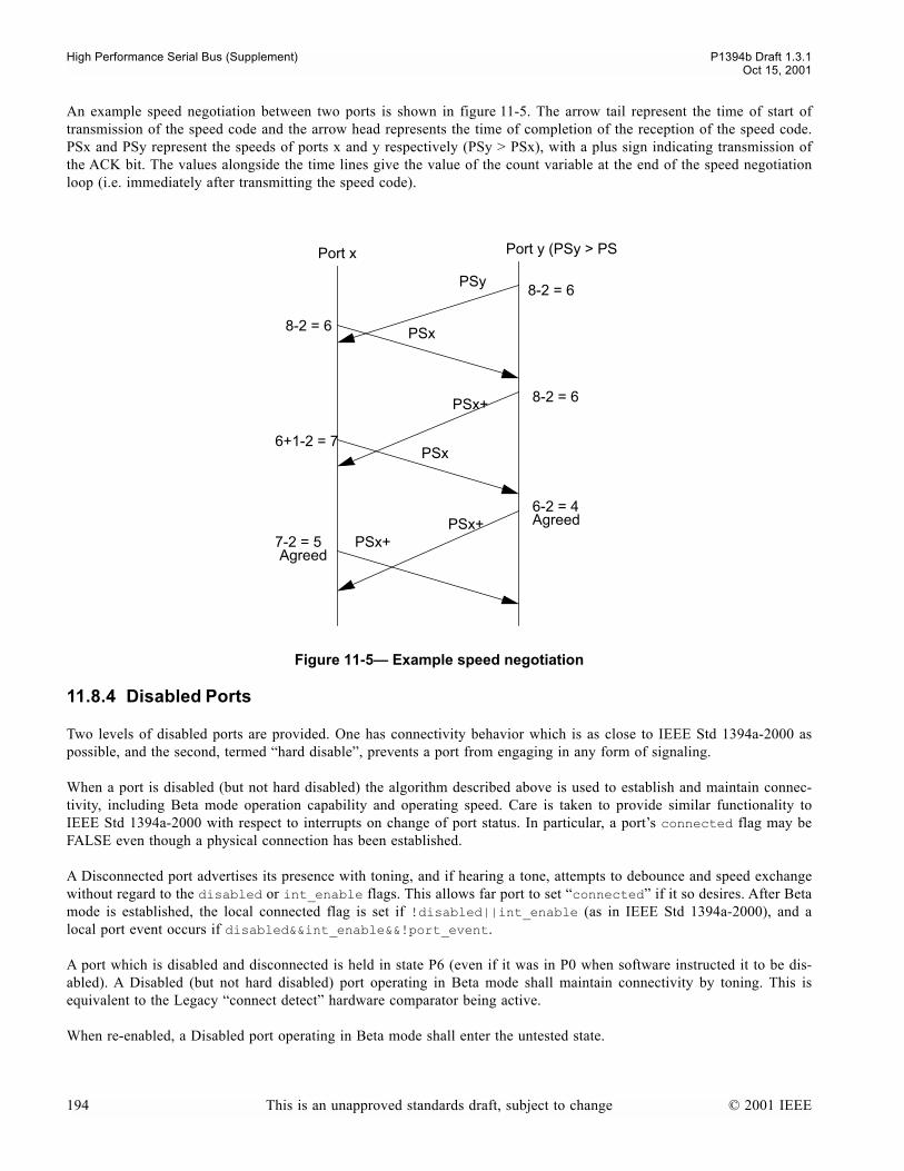
High Performance Serial Bus (Supplement) P1394b Draft 1.3.1Oct 15, 2001
An example speed negotiation between two ports is shown in figure 11-5. The arrow tail represent the time of start oftransmission of the speed code and the arrow head represents the time of completion of the reception of the speed code.PSx and PSy represent the speeds of ports x and y respectively (PSy > PSx), with a plus sign indicating transmission ofthe ACK bit. The values alongside the time lines give the value of the count variable at the end of the speed negotiationloop (i.e. immediately after transmitting the speed code).
11.8.4 Disabled Ports
Two levels of disabled ports are provided. One has connectivity behavior which is as close to IEEE Std 1394a-2000 aspossible, and the second, termed hard disable, prevents a port from engaging in any form of signaling.
When a port is disabled (but not hard disabled) the algorithm described above is used to establish and maintain connec-tivity, including Beta mode operation capability and operating speed. Care is taken to provide similar functionality toIEEE Std 1394a-2000 with respect to interrupts on change of port status. In particular, a ports connected flag may beFALSE even though a physical connection has been established.
A Disconnected port advertises its presence with toning, and if hearing a tone, attempts to debounce and speed exchangewithout regard to the disabled or int_enable flags. This allows far port to set connected if it so desires. After Betamode is established, the local connected flag is set if !disabled||int_enable (as in IEEE Std 1394a-2000), and alocal port event occurs if disabled&&int_enable&&!port_event.
A port which is disabled and disconnected is held in state P6 (even if it was in P0 when software instructed it to be dis-abled). A Disabled (but not hard disabled) port operating in Beta mode shall maintain connectivity by toning. This isequivalent to the Legacy connect detect hardware comparator being active.
When re-enabled, a Disabled port operating in Beta mode shall enter the untested state.
Figure 11-5 Example speed negotiation
PSy
PSx
PSx+ 8-2 = 6
8-2 = 6
PSx6+1-2 = 7
PSx+6-2 = 4
PSx+7-2 = 5Agreed
Agreed
Port x Port y (PSy > PS
8-2 = 6
194 This is an unapproved standards draft, subject to change © 2001 IEEE
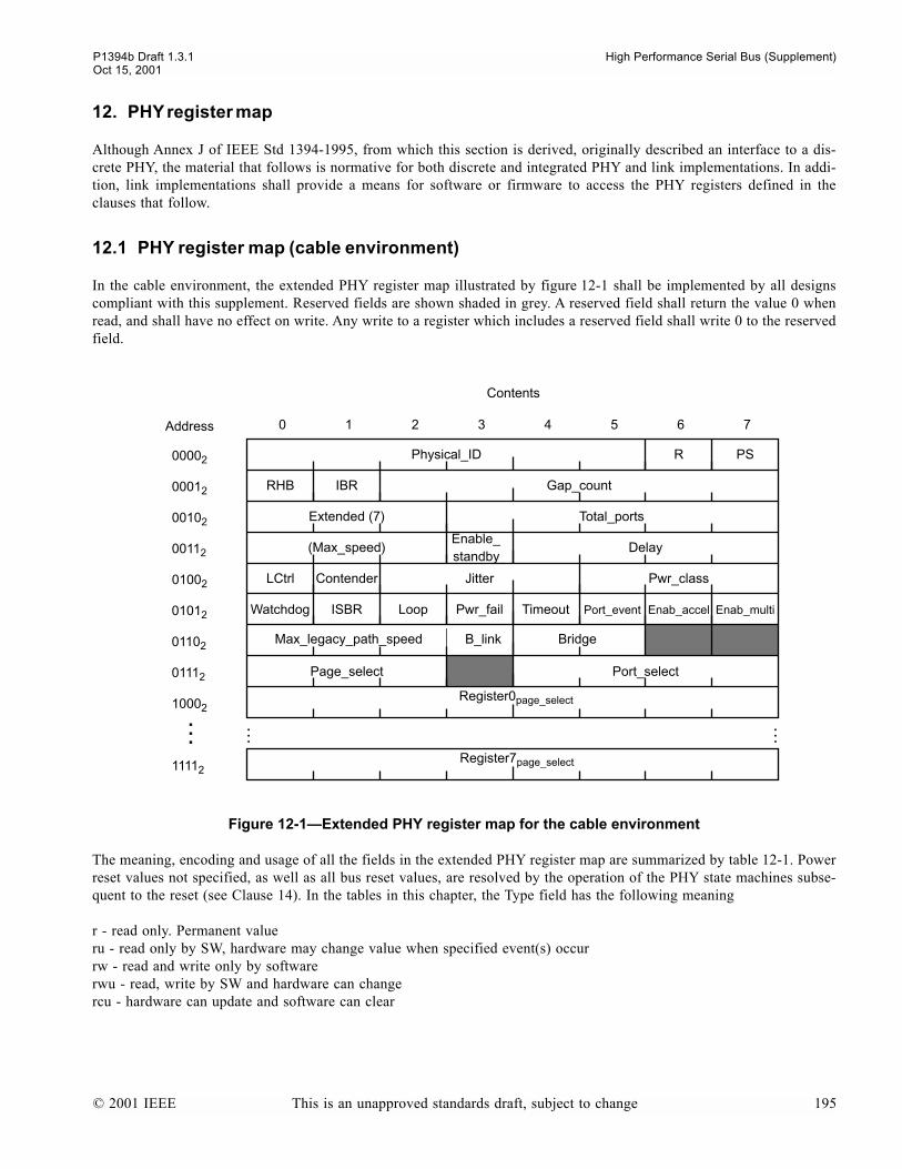
P1394b Draft 1.3.1 High Performance Serial Bus (Supplement)Oct 15, 2001
12. PHY register map
Although Annex J of IEEE Std 1394-1995, from which this section is derived, originally described an interface to a dis-crete PHY, the material that follows is normative for both discrete and integrated PHY and link implementations. In addi-tion, link implementations shall provide a means for software or firmware to access the PHY registers defined in theclauses that follow.
12.1 PHY register map (cable environment)
In the cable environment, the extended PHY register map illustrated by figure 12-1 shall be implemented by all designscompliant with this supplement. Reserved fields are shown shaded in grey. A reserved field shall return the value 0 whenread, and shall have no effect on write. Any write to a register which includes a reserved field shall write 0 to the reservedfield.
The meaning, encoding and usage of all the fields in the extended PHY register map are summarized by table 12-1. Powerreset values not specified, as well as all bus reset values, are resolved by the operation of the PHY state machines subse-quent to the reset (see Clause 14). In the tables in this chapter, the Type field has the following meaning
r - read only. Permanent valueru - read only by SW, hardware may change value when specified event(s) occurrw - read and write only by softwarerwu - read, write by SW and hardware can changercu - hardware can update and software can clear
Figure 12-1Extended PHY register map for the cable environment
Physical_ID PSR
RHB IBR Gap_count
(Max_speed)
Page_select
Extended (7) Total_ports
LCtrl Pwr_classContender
Port_select
Contents
0 1 2 3 4 5 6 7Address
00002
00012
00102
00112
01002
01012
01102
01112
Watchdog ISBR Loop Pwr_fail Enab_accel Enab_multi
Register0page_select
Register7page_select
10002
11112
Timeout Port_event
Delay
Jitter
Max_legacy_path_speed B_link Bridge
Enable_standby
© 2001 IEEE This is an unapproved standards draft, subject to change 195
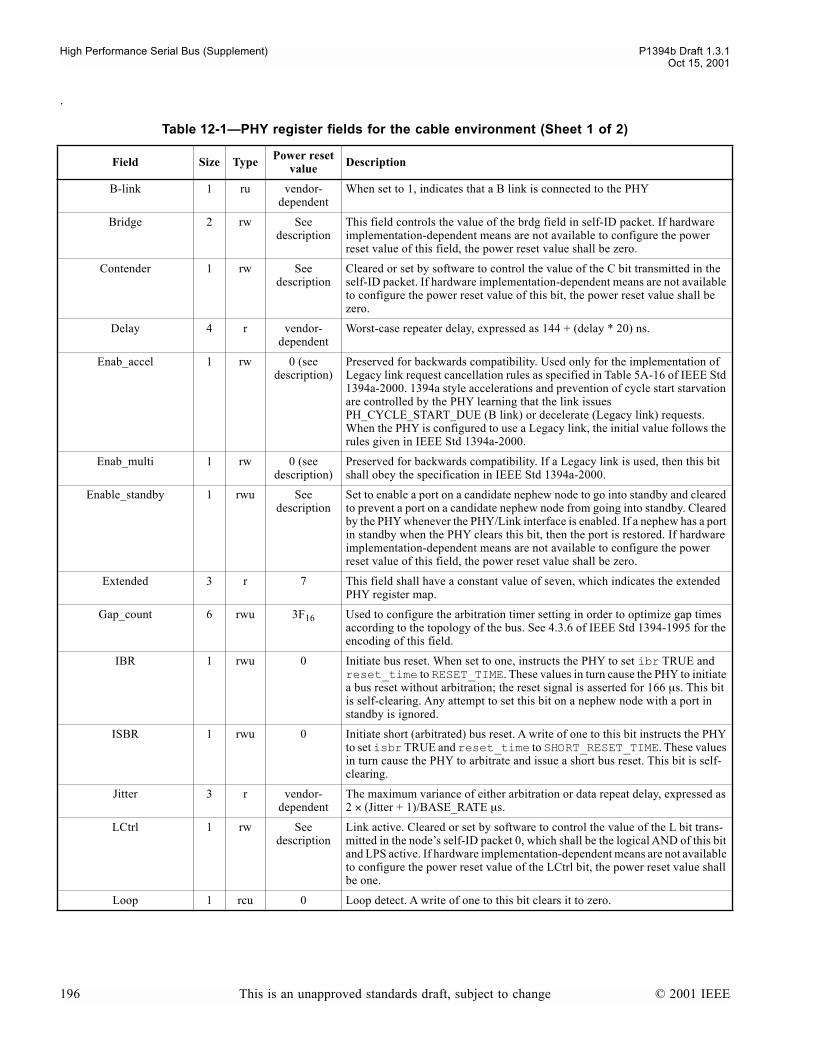
High Performance Serial Bus (Supplement) P1394b Draft 1.3.1Oct 15, 2001
.
Table 12-1PHY register fields for the cable environment (Sheet 1 of 2)
Field Size Type Power reset value Description
B-link 1 ru vendor-dependent
When set to 1, indicates that a B link is connected to the PHY
Bridge 2 rw See description
This field controls the value of the brdg field in self-ID packet. If hardware implementation-dependent means are not available to configure the power reset value of this field, the power reset value shall be zero.
Contender 1 rw See description
Cleared or set by software to control the value of the C bit transmitted in the self-ID packet. If hardware implementation-dependent means are not available to configure the power reset value of this bit, the power reset value shall be zero.
Delay 4 r vendor-dependent
Worst-case repeater delay, expressed as 144 + (delay * 20) ns.
Enab_accel 1 rw 0 (see description)
Preserved for backwards compatibility. Used only for the implementation of Legacy link request cancellation rules as specified in Table 5A-16 of IEEE Std 1394a-2000. 1394a style accelerations and prevention of cycle start starvation are controlled by the PHY learning that the link issues PH_CYCLE_START_DUE (B link) or decelerate (Legacy link) requests. When the PHY is configured to use a Legacy link, the initial value follows the rules given in IEEE Std 1394a-2000.
Enab_multi 1 rw 0 (see description)
Preserved for backwards compatibility. If a Legacy link is used, then this bit shall obey the specification in IEEE Std 1394a-2000.
Enable_standby 1 rwu See description
Set to enable a port on a candidate nephew node to go into standby and cleared to prevent a port on a candidate nephew node from going into standby. Cleared by the PHY whenever the PHY/Link interface is enabled. If a nephew has a port in standby when the PHY clears this bit, then the port is restored. If hardware implementation-dependent means are not available to configure the power reset value of this field, the power reset value shall be zero.
Extended 3 r 7 This field shall have a constant value of seven, which indicates the extended PHY register map.
Gap_count 6 rwu 3F16 Used to configure the arbitration timer setting in order to optimize gap times according to the topology of the bus. See 4.3.6 of IEEE Std 1394-1995 for the encoding of this field.
IBR 1 rwu 0 Initiate bus reset. When set to one, instructs the PHY to set ibr TRUE and reset_time to RESET_TIME. These values in turn cause the PHY to initiate a bus reset without arbitration; the reset signal is asserted for 166 µs. This bit is self-clearing. Any attempt to set this bit on a nephew node with a port in standby is ignored.
ISBR 1 rwu 0 Initiate short (arbitrated) bus reset. A write of one to this bit instructs the PHY to set isbr TRUE and reset_time to SHORT_RESET_TIME. These values in turn cause the PHY to arbitrate and issue a short bus reset. This bit is self-clearing.
Jitter 3 r vendor-dependent
The maximum variance of either arbitration or data repeat delay, expressed as 2 × (Jitter + 1)/BASE_RATE µs.
LCtrl 1 rw See description
Link active. Cleared or set by software to control the value of the L bit trans-mitted in the nodes self-ID packet 0, which shall be the logical AND of this bit and LPS active. If hardware implementation-dependent means are not available to configure the power reset value of the LCtrl bit, the power reset value shall be one.
Loop 1 rcu 0 Loop detect. A write of one to this bit clears it to zero.
196 This is an unapproved standards draft, subject to change © 2001 IEEE
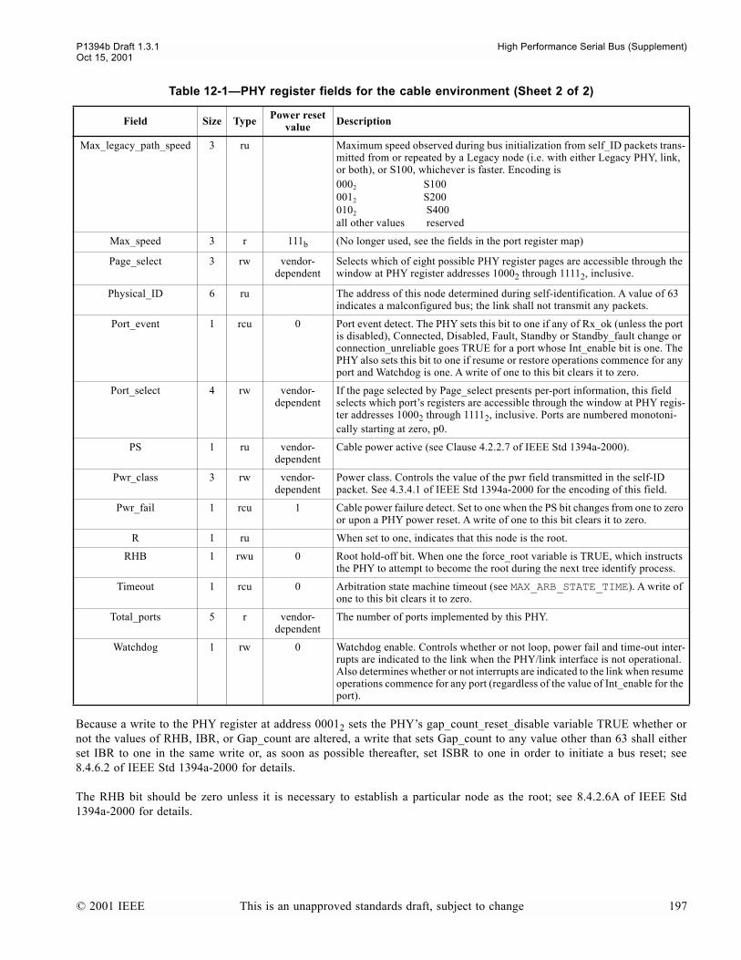
P1394b Draft 1.3.1 High Performance Serial Bus (Supplement)Oct 15, 2001
Because a write to the PHY register at address 00012 sets the PHYs gap_count_reset_disable variable TRUE whether ornot the values of RHB, IBR, or Gap_count are altered, a write that sets Gap_count to any value other than 63 shall eitherset IBR to one in the same write or, as soon as possible thereafter, set ISBR to one in order to initiate a bus reset; see8.4.6.2 of IEEE Std 1394a-2000 for details.
The RHB bit should be zero unless it is necessary to establish a particular node as the root; see 8.4.2.6A of IEEE Std1394a-2000 for details.
Max_legacy_path_speed 3 ru Maximum speed observed during bus initialization from self_ID packets trans-mitted from or repeated by a Legacy node (i.e. with either Legacy PHY, link, or both), or S100, whichever is faster. Encoding is0002 S1000012 S2000102 S400all other values reserved
Max_speed 3 r 111b (No longer used, see the fields in the port register map)
Page_select 3 rw vendor-dependent
Selects which of eight possible PHY register pages are accessible through the window at PHY register addresses 10002 through 11112, inclusive.
Physical_ID 6 ru The address of this node determined during self-identification. A value of 63 indicates a malconfigured bus; the link shall not transmit any packets.
Port_event 1 rcu 0 Port event detect. The PHY sets this bit to one if any of Rx_ok (unless the port is disabled), Connected, Disabled, Fault, Standby or Standby_fault change or connection_unreliable goes TRUE for a port whose Int_enable bit is one. The PHY also sets this bit to one if resume or restore operations commence for any port and Watchdog is one. A write of one to this bit clears it to zero.
Port_select 4 rw vendor-dependent
If the page selected by Page_select presents per-port information, this field selects which ports registers are accessible through the window at PHY regis-ter addresses 10002 through 11112, inclusive. Ports are numbered monotoni-cally starting at zero, p0.
PS 1 ru vendor-dependent
Cable power active (see Clause 4.2.2.7 of IEEE Std 1394a-2000).
Pwr_class 3 rw vendor-dependent
Power class. Controls the value of the pwr field transmitted in the self-ID packet. See 4.3.4.1 of IEEE Std 1394a-2000 for the encoding of this field.
Pwr_fail 1 rcu 1 Cable power failure detect. Set to one when the PS bit changes from one to zero or upon a PHY power reset. A write of one to this bit clears it to zero.
R 1 ru When set to one, indicates that this node is the root.
RHB 1 rwu 0 Root hold-off bit. When one the force_root variable is TRUE, which instructs the PHY to attempt to become the root during the next tree identify process.
Timeout 1 rcu 0 Arbitration state machine timeout (see MAX_ARB_STATE_TIME). A write of one to this bit clears it to zero.
Total_ports 5 r vendor-dependent
The number of ports implemented by this PHY.
Watchdog 1 rw 0 Watchdog enable. Controls whether or not loop, power fail and time-out inter-rupts are indicated to the link when the PHY/link interface is not operational. Also determines whether or not interrupts are indicated to the link when resume operations commence for any port (regardless of the value of Int_enable for the port).
Table 12-1PHY register fields for the cable environment (Sheet 2 of 2)
Field Size Type Power reset value Description
© 2001 IEEE This is an unapproved standards draft, subject to change 197

High Performance Serial Bus (Supplement) P1394b Draft 1.3.1Oct 15, 2001
The Watchdog bit serves two purposes. One is to determine whether or not an interrupt condition shall be indicated to thelink. The other is to create an interrupt condition whenever resume operations com-mence for any port. An interrupt con-dition is created either when any of the Loop, Pwr_fail, Timeout or Port_event bits transition from zero to one or whenthe PHY detects the absence of LPS and any of these same bits are one. Whether or not an interrupt condition shall beindicated to the link is determined by table 12-2.
The second function of Watchdog affects the creation of an interrupt condition. If this bit is one, Port_event shall be setto one and an interrupt condition shall be created whenever resume operations commence for any port.
Once an interrupt condition has been created, the method used to indicate it to the link depends upon the operational stateof the PHY/link interface. When the interface is operational it is used to report the INTERRUPT event; otherwise theINTERRUPT event causes the assertion of the LinkOn signal (see clause 14.4 for details).
The Loop, Pwr_fail, Timeout, and Port_event bits are unaffected by PHY register writes if the corresponding bit positionis zero. When the bit written to the PHY register is one, the corresponding bit is set to zero.
The upper half of the PHY register space, addresses 10002 through 11112, inclusive, provides a windows through whichadditional pages of PHY registers may be accessed. This supplement defines pages zero, one and seven: the Port Statuspage, the Vendor Identification page and a vendor-dependent page. Other pages are reserved.
Table 12-2PH_EVENT.indication(INTERRUPT) sources
Interrupt source LPS Watchdog Action
Port_event INTERRUPT
LoopPwr_failTimeout
00 a
a. Although the existence of the interrupt condition is not indicated to the link, the PHY register bits that describe the interrupt condition remain set until cleared by a PHY register write.
1 INTERRUPT
1 INTERRUPT
198 This is an unapproved standards draft, subject to change © 2001 IEEE
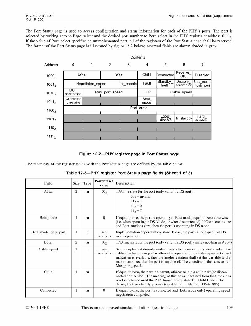
P1394b Draft 1.3.1 High Performance Serial Bus (Supplement)Oct 15, 2001
The Port Status page is used to access configuration and status information for each of the PHYs ports. The port isselected by writing zero to Page_select and the desired port number to Port_select in the PHY register at address 01112.If the value of Port_select specifies an unimplemented port, all of the registers of the Port Status page shall be reserved.The format of the Port Status page is illustrated by figure 12-2 below; reserved fields are shown shaded in grey.
The meanings of the register fields with the Port Status page are defined by the table below.
Figure 12-2PHY register page 0: Port Status page
Table 12-3PHY register Port Status page fields (Sheet 1 of 3)
Field Size Type Power reset value Description
AStat 2 ru 002 TPA line state for the port (only valid if a DS port):002 = invalid012 = 1102 = 0112 = Z
Beta_mode 1 ru 0 If equal to one, the port is operating in Beta mode, equal to zero otherwise (i.e. when operating in DS-Mode, or when disconnected). If Connected is one and Beta_mode is zero, then the port is operating in DS mode.
Beta_mode_only_port 1 r see description
Implementation dependent constant. If one, the port is not capable of DS mode operation
BStat 2 ru 002 TPB line state for the port (only valid if a DS port) (same encoding as AStat)
Cable_speed 3 r see description
Set by implementation-dependent means to the maximum speed at which the cable attached to the port is allowed to operate. If no cable-dependent speed indication is available, then the implementation shall set this variable to the maximum speed that the port is capable of. The encoding is the same as for Max_port_speed.
Child 1 ru If equal to zero, the port is a parent, otherwise it is a child port (or discon-nected or disabled). The meaning of this bit is undefined from the time a bus reset is detected until the PHY transitions to state T1: Child Handshake during the tree identify process (see 4.4.2.2 in IEEE Std 1394-1995).
Connected 1 ru 0 If equal to one, the port is connected and (Beta mode only) operating speed negotiation completed.
AStat BStat Child Connected
Contents
0 1 2 3 4 5 6 7Address
10002
10012
10102
10112
11002
11012
11102
11112
Receive_
Negotiated_speed Int_enable Fault
DisabledOK
Cable_speed
modeBeta_
Max_port_speed
Beta_mode_only_port
Port_error
Connection
LPPDC_connected
Disable_scrambler
Hard_disable
Standby_fault
In_standby
_unreliable
Loop_disable
© 2001 IEEE This is an unapproved standards draft, subject to change 199

High Performance Serial Bus (Supplement) P1394b Draft 1.3.1Oct 15, 2001
Connection_unreliable 1 rcu 0 If one, a Beta mode speed negotiation has failed or synchronization has failed. A write of 1 to this field resets the value to zero.
DC_connected 1 ru 0 If equal to one, the port has detected a DC connection to the peer port (by means of a 1394a-style connect detect circuit, if implemented).
Disable_scrambler 1 rw 0 When 1, the port inhibits the operation of the scrambler during transmission of a packet, such that transmitted scrambled data is equal in value to unscram-bled data. Note that control states and request types continue to be scrambled. Intended for use as a test mode only, not used during normal operation.
Disabled 1 rwu See description
If equal to one, the port is disabled. The value of this bit subsequent to a power reset is implementation-dependent. If a hardware configuration option is provided, a single option may control the power reset value for all ports. See also Hard_disable.
Fault 1 rcu 0 Set to one if an error is detected during a suspend or resume operation, cleared on exit from the suspend state or (suspend error) the peer port ceases normal signaling. A write of one to this bit or receipt of the appropriate remote com-mand packet (see clause 13.3.3.2) shall clear it to zero. When this bit is zeroed, both resume and suspend errors are cleared.
Hard_disable 1 rw 0 No effect unless the port is disabled. If equal to one, the port does not main-tain connectivity status on an AC connection when disabled. The values of Connected and Receive_OK are forced to zero.This flag can be used to force renegotiation of the speed of a connection.
Int_Enable 1 rw 0 Enable port event interrupts. When set to one, the PHY shall set Port_event to one if any of this ports Bias (unless the port is disabled), Connected, Dis-abled, Fault, Standby or Standby_fault bits change state.
Local_plug_present
(LPP in the map)
1 ru seedescription
Indicates that an external implementation dependent mechanism has deter-mined that there is at least a physical connection from the local port (maybe not connected at the far end). If there is no such mechanism, then this flag shall be set permanently to 1.
Loop_disable 1 ru 0 Set if the port has ben placed in the Loop_disable state as part of the loop free build process (the PHYs at either end of the connection are active, but if the connection itself were activated, then a loop would exist). Cleared on bus reset and on disconnection.
Max_port_speed 3 rw seedescription
The maximum speed at which a port is allowed to operate in Beta mode.The encoding is
0002S100
0012 S200
0102 S400
0112 S800
1002 S1600
1012 S3200
1102 reserved
1112 DS_mode_only port (port is not capable of operating in Beta mode)
An attempt to write to the register with a value greater than the hardware capability of the port results in the maximum value that the port is capable of being stored in the register.The port uses this register only when a new con-nection is established in Beta mode. The power reset value is the maximum value that the port is capable of, or the read-only value of 1112 for a DS_mode_only port.
Negotiated_speed 3 ru 0002 Indicates the maximum speed negotiated between this PHY port and its immediately connected port; the encoding is as for Max_port_speed. Set to a speed corresponding to the value of Port_speed (set on connection when in Beta_mode, or to value established during Self-ID when in DS mode).
Table 12-3PHY register Port Status page fields (Sheet 2 of 3)
Field Size Type Power reset value Description
200 This is an unapproved standards draft, subject to change © 2001 IEEE

P1394b Draft 1.3.1 High Performance Serial Bus (Supplement)Oct 15, 2001
The Vendor Identification page is used to identify the PHYs vendor and compliance level. The page is selected by writ-ing one to Page_select in the PHY register at address 01112. The format of the Vendor Identification page is illustrated byfigure 12-3 below; reserved fields are shown shaded in grey.
Port_error 8 rcu 0 Incremented whenever the port receives an INVALID codeword, unless the value is already 255. Cleared when read (including being read by means of a remote access packet). Intended for use by a single bus-wide diagnostic pro-gram.
Receive_OK 1 ru 0 In DS_mode indicates the reception of a debounced TpBias signal
In Beta_mode, indicates the reception of a continuous electrically valid sig-nal. Note, Receive_OK is set to false during the time that only connection tones are detected in Beta mode.
In_Standby 1 ru 0 Set to one if the port in standby (in states P7-P10, see clause 11.5).
Standby_fault 1 rcu 0 Set to one if an error is detected during a standby operation and cleared on exit from the standby state. A write of one to this bit or receipt of the appro-priate remote command packet (see clause 13.3.3.2) shall clear it to zero. When this bit is zeroed, standby errors are cleared.
Figure 12-3PHY register page 1: Vendor Identification page
Table 12-3PHY register Port Status page fields (Sheet 3 of 3)
Field Size Type Power reset value Description
Compliance_level
Contents
0 1 2 3 4 5 6 7Address
10002
10012
10102
10112
11002
11012
11102
11112
Vendor_ID
Product_ID
© 2001 IEEE This is an unapproved standards draft, subject to change 201

High Performance Serial Bus (Supplement) P1394b Draft 1.3.1Oct 15, 2001
The meanings of the register fields within the Vendor Identification page are defined by the table below.
12.2 Integrated link and PHY
The register map described in the preceding clauses is specified to assure interoperability between discrete link and PHYimplementations offered by different vendors. Because the PHY registers are the only means available to software to con-trol or query the state of the PHY, these register definitions are also critical to software.
An integrated link and PHY implementation, unless operating as a PIL, shall present the appropriate register map stan-dardized in the preceding clauses. The status that may be read from the registers and the behavior caused by a write to theregisters shall be identical with that of a discrete link and PHY combination.
When an integrated Link and PHY are operating as a PIL, the PIL shall present to software the registers from the attachedFOP. The registers in the PILs integrated PHY are not visible to software.
Table 12-4PHY register Vendor Identification page fields
Field Size Type Description
Compliance_level 8 r Standard to which the PHY implementation complies:
0 = not specified1 = IEEE Std 1394a-20002 = This standard
All other values reserved for future standardization
Vendor_ID 24 r The company ID or Organizationally Unique Identifier (OUI) of the manufacturer of the PHY. This number is obtained from the IEEE Registration Authority Commit-tee (RAC). The most significant byte of Vendor_ID appears at PHY register location 10102 and the least significant at 11002.
Product_ID 24 r The meaning of this number is determined by the company or organization that has been granted Vendor_ID. The most significant byte of Product_ID appears at PHY register location 11012 and the least significant at 11112.
202 This is an unapproved standards draft, subject to change © 2001 IEEE
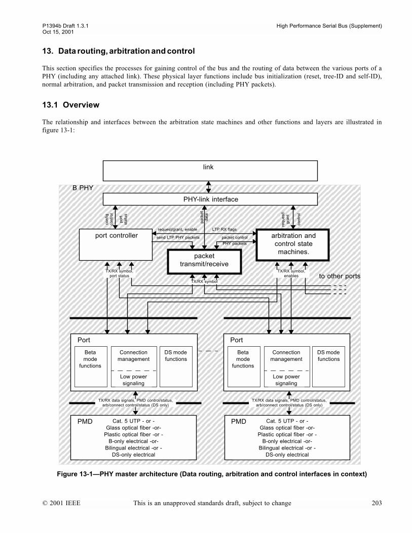
P1394b Draft 1.3.1 High Performance Serial Bus (Supplement)Oct 15, 2001
13. Data routing, arbitration and control
This section specifies the processes for gaining control of the bus and the routing of data between the various ports of aPHY (including any attached link). These physical layer functions include bus initialization (reset, tree-ID and self-ID),normal arbitration, and packet transmission and reception (including PHY packets).
13.1 Overview
The relationship and interfaces between the arbitration state machines and other functions and layers are illustrated infigure 13-1:
Figure 13-1PHY master architecture (Data routing, arbitration and control interfaces in context)
arbitration and control state machines.
Cat. 5 UTP - or -Glass optical fiber -or-
Plastic optical fiber -or -B-only electrical -or-
Bilingual electrical -or -DS-only electrical
link
B PHY
PHY-link interface
packet transmit/receive
port controller
DS mode functions
Beta mode
functions
Connection management
Low power signaling
Port
to other ports
pa
cke
t d
ata
send LTP PHY packets
req
ue
st\
gra
nt
packet control
request/grant, enable LTP RX flags
TX/RX symbol,port status
TX/RX symbol
TX/RX symbol,enables
con
tro
l
con
figco
ntr
ol
po
rtst
atu
s
PMD Cat. 5 UTP - or -Glass optical fiber -or-
Plastic optical fiber -or -B-only electrical -or-
Bilingual electrical -or -DS-only electrical
PMD
DS mode functions
Beta mode
functions
Connection management
Low power signaling
Port
PHY packets
TX/RX data signals, PMD control/status,arb/connect control/status (DS only)
TX/RX data signals, PMD control/status,arb/connect control/status (DS only)
© 2001 IEEE This is an unapproved standards draft, subject to change 203
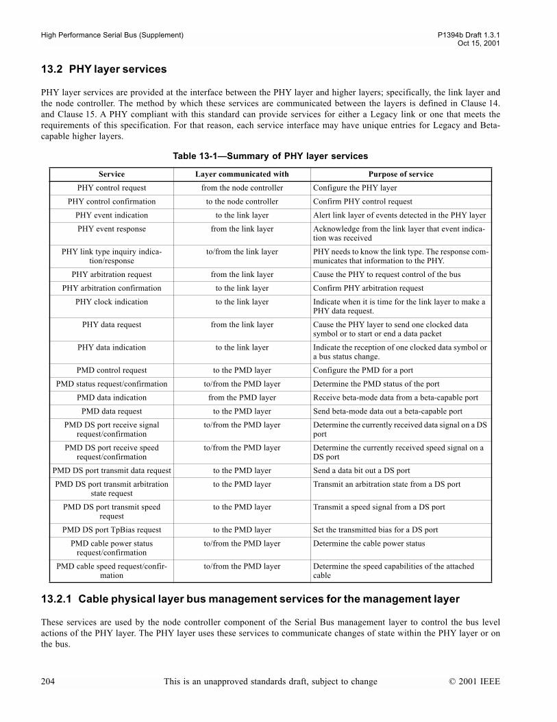
High Performance Serial Bus (Supplement) P1394b Draft 1.3.1Oct 15, 2001
13.2 PHY layer services
PHY layer services are provided at the interface between the PHY layer and higher layers; specifically, the link layer andthe node controller. The method by which these services are communicated between the layers is defined in Clause 14.and Clause 15. A PHY compliant with this standard can provide services for either a Legacy link or one that meets therequirements of this specification. For that reason, each service interface may have unique entries for Legacy and Beta-capable higher layers.
13.2.1 Cable physical layer bus management services for the management layer
These services are used by the node controller component of the Serial Bus management layer to control the bus levelactions of the PHY layer. The PHY layer uses these services to communicate changes of state within the PHY layer or onthe bus.
Table 13-1Summary of PHY layer services
Service Layer communicated with Purpose of service
PHY control request from the node controller Configure the PHY layer
PHY control confirmation to the node controller Confirm PHY control request
PHY event indication to the link layer Alert link layer of events detected in the PHY layer
PHY event response from the link layer Acknowledge from the link layer that event indica-tion was received
PHY link type inquiry indica-tion/response
to/from the link layer PHY needs to know the link type. The response com-municates that information to the PHY.
PHY arbitration request from the link layer Cause the PHY to request control of the bus
PHY arbitration confirmation to the link layer Confirm PHY arbitration request
PHY clock indication to the link layer Indicate when it is time for the link layer to make a PHY data request.
PHY data request from the link layer Cause the PHY layer to send one clocked data symbol or to start or end a data packet
PHY data indication to the link layer Indicate the reception of one clocked data symbol or a bus status change.
PMD control request to the PMD layer Configure the PMD for a port
PMD status request/confirmation to/from the PMD layer Determine the PMD status of the port
PMD data indication from the PMD layer Receive beta-mode data from a beta-capable port
PMD data request to the PMD layer Send beta-mode data out a beta-capable port
PMD DS port receive signal request/confirmation
to/from the PMD layer Determine the currently received data signal on a DS port
PMD DS port receive speed request/confirmation
to/from the PMD layer Determine the currently received speed signal on a DS port
PMD DS port transmit data request to the PMD layer Send a data bit out a DS port
PMD DS port transmit arbitration state request
to the PMD layer Transmit an arbitration state from a DS port
PMD DS port transmit speed request
to the PMD layer Transmit a speed signal from a DS port
PMD DS port TpBias request to the PMD layer Set the transmitted bias for a DS port
PMD cable power status request/confirmation
to/from the PMD layer Determine the cable power status
PMD cable speed request/confir-mation
to/from the PMD layer Determine the speed capabilities of the attached cable
204 This is an unapproved standards draft, subject to change © 2001 IEEE
P1394b Draft 1.3.1 High Performance Serial Bus (Supplement)Oct 15, 2001
13.2.1.1 PHY control request (PH_CONTROL.request)
The node controller uses this service to request the PHY layer to perform specific actions and to specify PHY layerparameters. It may also be used to request status about the PHY layer. The PHY layer shall service the request immedi-ately upon receipt by the PHY layer. This service is confirmed.
The following parameters are communicated by this service (see Clause 12. for descriptions of the PHY register fields):
- PHY register address. The register number in the PHY to be accessed.- Write. True when the indicated PHY register is to be written.- PHY register value. (Only valid when the Write parameter is true.) An 8-bit value to be written to the indicated PHY
register.
13.2.1.2 PHY control confirmation (PH_CONTROL.confirmation)
The PHY layer uses this service to confirm the results of a PHY control request service. The PHY layer shall communi-cate this service to the node controller upon completion of a PHY control request. There are no actions provided by thisservice. When the corresponding PHY control request Write parameter is false, the following parameter is communi-cated by this service:
- PHY register read value. The value of the indicated PHY register address in the corresponding PHY control request.
13.2.1.3 PHY event indication (PH_EVENT.indication)
The PHY layer uses this service to indicate PHY-level events to the node controller. There are no actions provided by thisservice. The PHY event response is defined as an acknowledge for this indication. The following parameters are commu-nicated via this service:
- Indication. This parameter contains the event detected by the PHY layer. The following values are defined for thisparameter:
PH_LINK_ON. The PHY layer has received a link_on packet addressed to this node or generated on power resetwhen the POWER_CLASS is 0 through 4.
PH_BUS_RESET_START. The PHY layer has detected a bus reset. Any outstanding requests (asynchronous, iso-chronous or immediate) are canceled.
NOTEMore than one BUS_RESET_START can be generated before the PH_BUS_RESET_COMPLETE event is generated.
PH_SELF_IDENTITY. Given during bus initialization, after a bus reset or after a restore. The Physical_ID and Rootparameters shall also be valid for this indication.
PH_BUS_RESET_COMPLETE. The PHY layer has detected a subaction gap after the bus reset process has started.PH_INTERRUPT. The PHY layer has generated an interrupt. The reason for the interrupt can be determined by us-
ing a PHY control request.PH_CABLE_POWER_FAIL. The PHY layer has detected a loss of cable power.PH_CONFIG_TIMEOUT. The PHY layer has not completed the PHY layer Initialization due to a time-out in the
Tree ID Process.
NOTEThe PH_CONFIG_TIMEOUT may indicate a loop in the topology that could not be broken (the loop consists entirely ofconnections between DS ports).
PH_MAX_ARB_STATE_TIMEOUT. The PHY layer has stayed in a state (except A0:Idle during the time thatidle_arb_state_timeout is FALSE, T0:Tree-ID Start, or a state that has an explicit time-out) for long-er than MAX_ARB_STATE_TIME.
PH_RESTORE_RESET. The PHY layer has determined that a bus reset occurred on the bus while the port was inStandby (may be generated in the Nephew at the end of a restore operation).
© 2001 IEEE This is an unapproved standards draft, subject to change 205
High Performance Serial Bus (Supplement) P1394b Draft 1.3.1Oct 15, 2001
PH_RESTORE_NO_RESET. The PHY layer is reporting that the port which was in Standby has commenced a re-store operation, and that the previous Physical_ID is invalid. The link shall not issue requests until it hassufficient information. This information includes having a valid Physical_ID before making any bus re-quest, knowing the isochronous interval before making an isochronous request and/or knowing the asyn-chronous interval before making a NEXT_EVEN or NEXT_ODD asynchronous request (it may make aCURRENT request). This indication shall only be generated in the Nephew.
NOTEOther nodes will not have completed their reset processing until the Indication of PH_BUS_RESET_COMPLETE has beenreceived.
- Physical_id. (Conditional, valid only when the Indication is PH_SELF_IDENTITY). This parameter contains aunique 6 bit number, as determined by the self-ID process.
- Root. (Conditional, valid only when the Indication is PH_SELF_IDENTITY). This boolean parameter is TRUE onlywhen this node is the root, as determined by the tree ID process.
13.2.1.4 PHY event response (PH_EVENT.response)
The link layer synthesizes this service to acknowledge the receipt of a PHY event indication ofPH_BUS_RESET_START, PH_RESTORE_NO_RESET, and PH_RESTORE_RESET.
13.2.1.5 PHY link type inquiry indication (PH_LINK_TYPE.indication) and response (PH_LINK_TYPE.response)
The PHY layer uses this service to request the type of link attached to the PHY. There are no actions provided by this ser-vice. The PHY link type inquiry response is defined as an acknowledge for this indication. The following parameters arecommunicated via the response service:
- linkType. This parameter contains the event detected by the PHY layer. The following values are defined for this pa-rameter:
B_LINK. The link attached to this PHY is a B link.LEGACY_LINK. The link attached to this PHY is a Legacy link.
NOTEThe C-code uses a unified PH_LINK_TYPE_response which combines the functions of this indication and thecorresponding response.
13.2.2 PHY layer arbitration services for the link layer
These services are used to communicate arbitration requests between the PHY layer and the link layer.
13.2.2.1 PHY arbitration request (PH_ARB.request)
The link layer uses this service to request the PHY layer to start arbitration for the bus. The PHY layer shall arbitrate forthe bus using the method specified by the service parameters. The PHY layer shall service the request immediately uponreceipt from the link layer.
For Legacy link layers, this service shall be confirmed when the arbitration process completes. If a node loses arbitration(PH_ARB.confirmation with an arbitration request status of LOST), it shall reissue the arbitration request.
For B-capable link layers, the asynchronous (CURRENT, NEXT_EVEN, NEXT_ODD), cycle master, isochronous(ISOCH_ODD and ISOCH_EVEN), and immediate requests have independent confirmations. This allows one request ofeach type to be active at a time.
The following parameters are communicated via this service:
206 This is an unapproved standards draft, subject to change © 2001 IEEE

P1394b Draft 1.3.1 High Performance Serial Bus (Supplement)Oct 15, 2001
- reqType. This parameter contains the method of arbitration performed by the PHY arbitration request. The methodof arbitration shall be one of the following:
PH_IMMED_REQ. A PHY arbitration confirmation with an Arbitration Request Status of WON shall be commu-nicated to the link layer as soon as the bus is idle. (The link layer uses this method to send an acknowledgepacket.)
PH_NEXT_EVEN (B-capable). The PHY layer shall arbitrate as required for the next even fairness interval (or thecurrent interval, if even). This supersedes any previously queued PH_NEXT_ODD orPH_NEXT_CURRENT request.
PH_NEXT_ODD (B-capable). The PHY layer shall arbitrate as required for the next odd fairness interval (or thecurrent interval, if odd). This supersedes any previously queued PH_NEXT_EVEN orPH_NEXT_CURRENT request.
PH_CURRENT (B-capable). The PHY layer shall arbitrate as required for the current fairness interval. This super-sedes any previously queued PH_NEXT_ODD or PH_NEXT_EVEN request.
PH_ISOCH_REQ_EVEN (B-capable). The PHY layer shall arbitrate as required for the next even isochronous in-terval (or the current interval, if even). This supersedes any previously queued PH_ISOCH_REQ_ODDrequest.
PH_ISOCH_REQ_ODD (B-capable). The PHY layer shall arbitrate as required for the next odd isochronous inter-val (or the current interval, if odd). This supersedes any previously queued PH_ISOCH_REQ_EVEN re-quest.
PH_CYC_START_REQ (B-capable). The PHY layer shall arbitrate as required for the current fairness interval withhigher priority than any other queued asynchronous request.
PH_LPS_ACTIVE. The PHY shall report the L bit in any subsequent self_ID as TRUE if lctrl is also TRUE.PH_LPS_INACTIVE. The PHY shall report the L bit in any subsequent self_ID as FALSE, and shall give a
PHY_Event of LINK_ON if it receives a Link_On packet.PH_ISOCH_PHASE_ODD (B-capable). The PHY layer shall enter the isochronous interval (if not already in the
isochronous interval) and set the phase to odd. The link issues this on receipt of a cycle start packet if itintends to perform isochronous transfers.
PH_ISOCH_PHASE_EVEN (B-capable). The PHY layer shall enter the isochronous interval (if not already in theisochronous interval) and set the phase to even. The link issues this on receipt of a cycle start packet if itintends to perform isochronous transfers.
PH_CYCLE_START_DUE. The PHY layer shall refrain from using accelerations and arbitrations which could re-sult in cycle start starvation (i.e. until it receives a PH_CYCLE_START_SEEN, PH_ISOCH_REQ orPH_ISOCH_PHASE_*, or it receives or transmits a CYCLE_START_* token). Should be issued by cycleslaves once every isochronous period, as soon as possible after the local clock indicates the start of a newisochronous period. The PHY layer shall permanently refrain from using accelerations and arbitrationswhich could result in cycle start starvation from power reset or PHY-link interface disable until it receivesthis indication.
PH_CYCLE_START_SEEN (Legacy). The PHY layer may use accelerations once again. (Used after accelerationsare disabled by PH_CYCLE_START_DUE).
PH_ISOCH_REQ (Legacy). The PHY layer shall start arbitration as soon as the bus is idle. (The link layer uses thismethod to send an isochronous packet).
PH_PRIORITY_REQ (Legacy). The PHY layer shall arbitrate as required for the current fairness interval.PH_FAIR _REQ (Legacy). The PHY layer shall start arbitration for the current fairness interval if its arb_enable
flag is set, otherwise it shall start arbitration at the next arbitration reset gap.
© 2001 IEEE This is an unapproved standards draft, subject to change 207

High Performance Serial Bus (Supplement) P1394b Draft 1.3.1Oct 15, 2001
- speed. (conditional, only valid when reqType is PH_IMMED_REQ, PH_NEXT_EVEN, PH_NEXT_ODD,PH_CURRENT, PH_ISOCH_REQ_EVEN, PH_ISOCH_REQ_ODD, PH_PRIORITY_REQ,PH_CYC_START_REQ, PH_ISOCH_REQ or PH_FAIR_REQ). This parameter indicates which data rate is to beused to generate all subsequent PHY clock indication events until the next PHY data request with a DATA_END pa-rameter. The speed code shall be one of those listed in table 13-2:
- beta_format (conditional, only valid when reqType is PH_IMMED_REQ (B-capable), PH_NEXT_EVEN,PH_NEXT_ODD, PH_CURRENT, PH_ISOCH_REQ_EVEN, PH_ISOCH_REQ_ODD, or PH_CYC_START_REQ.Shall be assumed to be False if reqType is PH_IMMED_REQ for a Legacy link). Booean parameter:
True. The PHY layer shall transmit the packet in Beta format.False. The PHY layer shall transmit the packet in Legacy format unless it can determine that the packet will be de-
livered correctly if transmitted in Beta format
13.2.2.2 PHY arbitration confirmation(PH_ARB.conf)
The PHY layer uses this service to confirm the results of a PHY arbitration request service. The PHY layer shall commu-nicate this service to the link layer upon completion of a PHY arbitration request. There are no actions provided by thisservice. The following parameters are communicated via this service:
- Confirmation. This parameter contains the result of a PHY arbitration request action. The following values are de-fined for this parameter:
PH_WON (Legacy). The PHY layer has won arbitration as a result of the most recently issued PH_ARB.request orPH_DATA.request of PH_REQ_DATA_PREFIX.
PH_LOST (Legacy). If there is an outstanding PH_ARB.request, then the PHY layer has lost arbitration. Any out-standing request is cancelled. Issued whether or not a request was issued, to indicate start of cancellationperiod. Will only be issued for cancellation of asynchronous requests. PH_LOST shall always be followedimmediately by PH_DATA_PREFIX (when enab_accel is FALSE) or PH_DATA_BYTE orPH_DATA_END (when enab_accel is TRUE)1,2.
Table 13-2Cable physical layer speed codes
Speed code Comment
S100 Base rate, all nodes are required to be capable of transmitting and receiving packets at this rate.
S200 All nodes capable of the S200 data rate are also required to be capable of operating at the S100 data rate1.
S400 All nodes capable of the S400 data rate are also required to be capable of operating at the S100 and S200 data rates1.
S800 All nodes capable of the S800 data rate are also required to be capable of operating at the S100, S200 and S400 data ratea.
a. For ports operating in Beta mode, data rates lower than the negotiated rate are supported using the data padding technique described in clause 10.
S1600 All nodes capable of the S1600 data rate are also required to be capable of operating at the S100, S200, S400 and S800 data rates1.
S3200 All nodes capable of the S3200 data rate are also required to be capable of operating at the S100, S200, S400, S800 and S1600 data rates1.
1 In the absence of an explicit handshake/acknowledgement with the link layer, an actual implementation needs to ensure that all requestssubject to cancellation (including those possibly in flight to the PHY layer) issued by the link layer prior to reception of the PH_LOST atthe link layer are cancelled appropriately by the PHY layer.
2 An implementation of the PHY/Link interface need not implement PH_LOST as an explicit signal. A link may infer PH_LOST fromPH_DATA_PREFIX (when enab_accel is FALSE), or PHY_DATA_PREFIX followed by either more than one PH_DATA_BYTE orPH_DATA_END (when enab_accel is TRUE).
208 This is an unapproved standards draft, subject to change © 2001 IEEE
P1394b Draft 1.3.1 High Performance Serial Bus (Supplement)Oct 15, 2001
PH_WON_IMMED (B-capable). The PHY layer has won arbitration as a result of the most recently issuedPH_ARB.request of PH_IMMED_REQ
PH_WON_ISOCH (B-capable). The PHY layer has won arbitration as a result of the most recently issuedPH_ARB.request of PH_ISOCH_REQ_EVEN or PH_ISOCH_REQ_ODD.
PH_WON_CYCLE_START (B-capable).The PHY layer has won arbitration as a result of the most recently issuedPH_ARB.request of PH_CYC_START_REQ.
PH_WON_ASYNC (B-capable). The PHY layer has won arbitration as a result of the most recently issuedPH_ARB.request of PH_NEXT_EVEN, PH_NEXT_ODD or PH_CURRENT.
- Speed_Code (conditional, only valid when Confirmation is not PH_LOST or PH_WON). Indicates the speed that isused for the packet using this arbitration opportunity. The values defined for this parameter are the same as those intable 13-2.
- pkt_format (conditional, only valid when PH_arb_indication is not PH_LOST or PH_WON). This Boolean parame-ter indicates the format that was requested for the packet using this arbitration opportunity.
NOTE.
13.2.3 PHY layer data services for the link layer
These services are used to communicate data symbols and control information between the PHY layer and the link layer.
13.2.3.1 PHY clock indication (PH_CLOCK.indication)
The PHY layer uses this service to indicate to the link layer that a data symbol transmission is about to occur. There areno actions provided by this service. The link layer shall respond to this indication with a PHY data request. No parame-ters are communicated via this service.
The PHY layer shall begin communicating this indication to the link layer after it has communicated a PHY arbitrationconfirmation other than PH_LOST. The PHY layer shall stop communicating this indication to the link layer after the linklayer communicates a PH_DATA.request of PH_REQ_DATA_END, PH_REQ_DATA_PREFIX orPH_REQ_SUBACTION_END.
This indication occurs once for each symbol time as specified by the corresponding PHY arbitration request.
13.2.3.2 PHY data request (PH_DATA.request)
The link layer uses this service to control the PHY layers transmission of clocked data symbols. The link layer shallcommunicate one PHY data request for each PHY clock indication. The PHY layer shall service the request immediatelyupon receipt by the PHY layer. There is no confirmation for this request.
The following parameters are communicated via this service:
- reqType. This parameter contains the type of symbol to be transmitted on the bus. The following values are definedfor this parameter:
PH_REQ_DATA. The PHY layer shall transmit an 8-bit data byte.PH_REQ_DATA_PREFIX (Legacy). The PHY layer shall stop sending clocked data bytes and prepare to transmit
a concatenated packet. When ready to transmit the concatenated packet, the PHY layer gives aPH_Confirmation of PH_WON.
PH_REQ_DATA_END. The PHY layer shall stop sending clocked data bytes and terminate the packet appropriate-ly. If, in the case of a Legacy link, the PHY layer can determine that the packet marks the end of a subac-tion, it shall behave as if it had received a PH_REQ_SUBACTION_END.
PH_REQ_SUBACTION_END (B-capable). The PHY layer shall stop sending clocked data bytes and terminate thepacket appropriately. It may terminate the packet with a GRANT or GRANT_ISOCH token to satisfy apipelined request from the link or a request received over the bus of the current phase, or may end the in-
© 2001 IEEE This is an unapproved standards draft, subject to change 209
High Performance Serial Bus (Supplement) P1394b Draft 1.3.1Oct 15, 2001
terval if appropriate. The link shall give this indication in preference to PH_REQ_DATA_END wheneverthe packet marks the end of a subaction (e.g. broadcast packets, isochronous packets, asynchronous streampackets and ACK packets.
PH_REQ_HOLD. The PHY layer shall continue to transmit DATA_PREFIX. The link layer issues this request afterreceiving a confirmation other than PH_LOST and before it issues any other data request.
- data (conditional, only present when the reqType is PH_DATA_BYTE). This parameter shall contain the 8-bit valueto be transmitted.
- speed (conditional, only present when reqType is PH_REQ_DATA_PREFIX). This parameter shall contain the speedcode to be transmitted. The values defined for this parameter are the first 3 entries shown in table 13-2.
Once the link layer starts sending a data byte, it shall transmit the entire packet.
The link layer shall stop transmitting within a MAX_BUS_OCCUPANCY of receiving a confirmation other thanPH_LOST.
13.2.3.3 PHY data indication (PH_DATA.indication)
The PHY layer uses this service to indicate to the link layer changes in the state of the PHY layer. These changes caninclude received data, PHY layer originated data (which is copied to the link layer) and other bus events. The PHY layershall communicate this indication to the link layer for each data byte transferred to the link. If the PHY layer is not trans-ferring data bytes to the link, it uses this indication to communicate indications needed by the link layer. No response isdefined for this indication. The following parameters are communicated via this service:
- Indication. This parameter contains the information decoded by the PHY which is needed by the link layer. The fol-lowing values are defined for this parameter:
PH_DATA_START. Delivery of clocked data to the link is about to begin.PH_DATA_BYTE. An 8-bit data byte is delivered to the link.PH_DATA_PREFIX. The bus is busy. This indication is always given before a PH_DATA_START, and may be giv-
en after the last data byte of a packet.PH_DATA_END. The last data byte of a packet has been delivered and the bus is no longer busy.PH_SUBACTION_GAP. (Legacy) A Subaction Gap event has been detected on the bus. Any outstanding isochro-
nous request will be canceled.(B-capable) an asynchronous Start token is delivered to the link.
PH_ARBITRATION_RESET_GAP (Legacy). An Arbitration Reset Gap event has been detected on the bus.PH_ARB_RESET_ODD (B-capable). An Arbitration Reset Odd token is delivered to the link.PH_ARB_RESET_EVEN (B-capable). An Arbitration Reset Even token is delivered to the link.PH_ISOCH_ODD (B-capable). A Cycle Start Odd token is delivered to the link.PH_ISOCH_EVEN (B-capable). A Cycle Start Even token is delivered to the link.
- Speed_Code (conditional, only present when the Indication is PH_DATA_START). This parameter indicates whichdata rate (see table 13-2) will be used during all subsequent PHY data indication services for the current packet.
- Data_Byte (conditional, only present when the Indication is PH_DATA_BYTE). This parameter contains the 8-bitdata value.
- pkt_format (conditional, only present when the Indication is PH_DATA_START). Shall be one of the following:LEGACY, The following packet was transmitted in Legacy format.BETA. The following packet was transmitted in Beta format.
13.2.4 PHY/link Interface block
This clause is written in terms of an abstract PHY/link block, which implements the services specified above. In additionit tracks the arbitration state machine and deals with link interface reset and bring up issues.
On link initiated interface resets (via LPS), the PHY/link block shall
210 This is an unapproved standards draft, subject to change © 2001 IEEE
P1394b Draft 1.3.1 High Performance Serial Bus (Supplement)Oct 15, 2001
a) ensure that no PH_ARB.request which was previously issued by the link (before the link issued the interfacereset) is sent to the PHY for queueing
b) invoke cancel_requests() at the PHY by issuing PH_LPS_INACTIVEc) handshake with the PHY to terminate the packet if transmitting when the interface reset commencesd) remember the last PH_SELF_IDENTITY and PH_ARB_RESET_ODD/EVEN issued by the arbitration state
machine for possible transmission to the link during the completion of the interface resete) ensure that no partial packets or partial status transfers are sent to the linkf) issue a PH_DATA.request(PH_REQ_DATA_END) to handshake with the PHY if granted during the reset interval
On PHY initiated bus reset and restore on a nephew, the PHY/link block shall
a) handshake with PH_EVENT_response (after which the arbitration state machine shall cancel requests)b) ensure that no PH_ARB.request is sent to the PHY for queueing until the bus reset or restore event (as
appropriate) has been received by the link layer and any in-flight requests have been flushed
13.2.5 PMD services for the PHY layer
There is an individual Physical Media Dependent (PMD) layer for each port on a PHY, therefore there is an instance ofeach of the following service interfaces for each port (except for PMD_PS.request, which is not port specific).
13.2.5.1 PMD control request (PMD_CONTROL.request)
The PHY layer uses this service to control the PMD layer. The PMD layer shall service the request immediately uponreceipt by the PMD layer. There is no confirmation for this request.
The following parameters are communicated via this service:
- control_request. This parameter contains the type of request to be made to the PMD layer. The following values aredefined for this parameter:
PMD_CROSSOVER. Implement a TPA/TPB crossover (see clause 9.4.5).PMD_NO_CROSSOVER. Remove any TPA/TPB crossover (see clause 9.4.5).PMD_TONE_ON. Instructs the PMD to generate a tone (see clause 6.6.1).PMD_TONE_OFF. Instructs the PMD to cease generating a tone, remove the signalling bias voltage and set the port
transmitters to high impedance.PMD_SELECT_BPORT. Selects the bport PMD for Beta mode I/O.PMD_SELECT_DS_PORT. Selects the dsport PMD for data, arbitration line states and common-mode speed sig-
nalsPMD_UNSELECT_PORT. Removes control of port signalling from bport or dsport (as appropriate).
- speed (conditional, only present when the PH_data_request is PMD_SELECT_BPORT). This parameter indicatesthe operating speed of the port.
13.2.5.2 PMD status request (PMD_STATUS.request) and confirmation (PMD_STATUS.confirmation)
The PHY layer uses these service pairs to request status from the PMD layer. The PMD layer shall service the requestimmediately upon receipt and respond with the PMD status confirmation.
NOTEThe C-code uses a unified PMD_STATUS_request which combines the functions of this request and the correspondingconfirmation.
The following parameters are communicated by the PMD confirmation:
- PMD_BIAS_DETECT. Undebounced output of the PMD bias comparator
© 2001 IEEE This is an unapproved standards draft, subject to change 211

High Performance Serial Bus (Supplement) P1394b Draft 1.3.1Oct 15, 2001
- PMD_CONNECT_DETECT. Undebounced PMD output of connect_detect comparator- PMD_LOCAL_PLUG_PRESENT. When AC coupled (possibly via, say, an optical transceiver), this parameter indi-
cates that an external implementation dependent mechanism has determined that there is at least a physical connec-tion from the local node to a cable (although there may not be a connection to the peer port). Used to avoidperforming connection toning if there is definitely no connection. If there is no such mechanism, then this parametershall be set permanently to TRUE.
- PMD_SIGNAL_DETECT. Set by PMD if it detects a signal as specified by the signal_detect specification of thespecific PMD.
- PMD_AUTOCROSSOVER_SUPPORTED. Set by PMD if the crossover control requests are supported.
13.2.5.3 PMD Beta port data indication (PMD_DATA.indication)
The PMD layer uses this service to indicate to the PHY layer PMD layer originated data (which is copied to the PHYlayer). The following parameter iscommunicated via this service:
- data. The data bit received.
13.2.5.4 PMD Beta mode port transmit data request (PMD_DATA.request)
The PHY layer uses this service to transmit a data bit on a port operating in Beta mode. The PMD layer shall service therequest immediately upon receipt by the PMD layer. There is no confirmation for this request.
The following parameter is communicated via this service:
- data. The data bit to be transmitted.
13.2.5.5 PMD DSport receive signal request (PMD_DSPORT_SIGNAL.request) and confirmation (PMD_DSPORT_SIGNAL.confirmation)
The PHY layer uses these service pairs to request the current signal being received from a PMD layer operating in DSmode. The PMD layer shall service the request immediately upon receipt and respond with a confirmation.
NOTEThe C-code uses a unified PMD_DSPORT_SIGNAL_request which combines the functions of this request and thecorresponding confirmation.
The following parameters are communicated by the PMD confirmation:
- RX_arb. This takes one of the values RX_IDLE, RX_PARENT_NOTIFY, RX_REQUEST_CANCEL,RX_IDENT_DONE, RX_SELF_ID_GRANT, RX_REQUEST, RX_ROOT_CONTENTION, RX_GRANT,RX_SUSPEND, RX_PARENT_HANDSHAKE, RX_DATA_END, RX_CHILD_HANDSHAKE,RX_DISABLE_NOTIFY, RX_DATA_PREFIX, RX_BUS_RESET
- data. This provides the values of TPA and TPB as interpreted by the data comparators.
13.2.5.6 PMD DSport receive speed request (PMD_DSPORT_RXSPEED.request) and confirmation (PMD_DSPORT_RXSPEED.confirmation)
The PHY layer uses this service to request the current speed signal being received from a PMD layer operating in DSmode. The PMD layer shall service the request immediately upon receipt and respond with a confirmation.
NOTEThe C-code uses a unified PMD_DSPORT_RXSPEED_request which combines the functions of this request and thecorresponding confirmation.
The following parameters are communicated by the PMD confirmation:
- RX_S200. The PMD has detected a DS mode S200 speed signal.
212 This is an unapproved standards draft, subject to change © 2001 IEEE
P1394b Draft 1.3.1 High Performance Serial Bus (Supplement)Oct 15, 2001
- RX_S400. The PMD has detected a DS mode S400 speed signal.
The value returned by this service shall be the minimum of the received speed signal and the speed capability of the port.Thus if the local port is only S200 capable, but the peer port is sending a S400 speed signal, this service will report S200.
13.2.5.7 PMD DSport transmit data request (PMD_DSPORT_DATA.request)
The PHY layer uses this service to transmit a data bit on a port operating in DS mode. The PMD layer shall service therequest immediately upon receipt by the PMD layer. There is no confirmation for this request.
The following parameter is communicated via this service:
- pd. The port data to be transmitted encoded as the values for TPA and TPB.
13.2.5.8 PMD DSport transmit arbitration state request (PMD_DSPORT_ARB.request)
The PHY layer uses this service to transmit an arbitration line state on a port operating in DS mode. The PMD layer shallservice the request immediately upon receipt by the PMD layer. There is no confirmation for this request.
The following parameter is communicated via this service:
- arb. This takes one of the values TX_IDLE, TX_REQUEST, TX_GRANT, TX_DISABLE_NOTIFY,TX_PARENT_NOTIFY, TX_SUSPEND, TX_DATA_PREFIX, TX_CHILD_NOTIFY, TX_IDENT_DONETX_DATA_END, TX_BUS_RESET.
13.2.5.9 PMD DSport transmit speed request (PMD_DSPORT_TXSPEED.request)
The PHY layer uses this service to transmit speed signal on a port operating in DS mode. The PMD layer shall service therequest immediately upon receipt by the PMD layer. There is no confirmation for this request.
The following parameter is communicated via this service:
- speed. This parameter shall contain the speed code to be transmitted. The values defined for this parameter are thefirst 3 entries shown in table 13-2.
13.2.5.10 PMD DSport TpBias request (PMD_DSPORT_TPBIAS.request)
The PHY layer uses this service to conrol the common mode voltage (TpBias) on a port operating in DS mode. The PMDlayer shall service the request immediately upon receipt by the PMD layer. There is no confirmation for this request.
The following parameter is communicated via this service:
- sig. This takes one of the following valuesGND instructs the PMD to drive the common mode voltage on TPA to VG. Bias_On instructs the PMD to generate the TpBias voltage on TPA.ZZ instructs the PMD to cease generating TpBias and set TPA to high impedance.
13.2.5.11 PMD cable power status request (PMD_PS.request) and confirmation (PMD_PS.confirmation)
The PHY layer uses this request/confirmation pair to obtain the nodes cable power status. The confirmation returnsTRUE if cable power is active on any of the PMD layers, otherwise FALSE.
NOTEThe C-code uses a unified PMD_PS_request which combines the functions of this request and the correspondingconfirmation.
© 2001 IEEE This is an unapproved standards draft, subject to change 213
High Performance Serial Bus (Supplement) P1394b Draft 1.3.1Oct 15, 2001
13.2.5.12 PMD cable speed request (PMD_CABLE_SPEED.request) and confirmation (PMD_CABLE_SPEED.confirmation)
The PHY layer uses this request/confirmation pair to obtain the speed capability of that cable currently attached to theport. The confirmation returns TRUE if cable power is active on any of the PMD layers, otherwise FALSE. The followingparameters are communicated via the confirmation service:
- speed. This parameter indicates the maximum data rate supported by the cable currently attached to the port. Thespeed code shall be one of those listed in table 13-2:
NOTEThe C-code uses a unified PMD_CABLE_SPEED_request which combines the functions of this request and thecorresponding confirmation.
214 This is an unapproved standards draft, subject to change © 2001 IEEE

P1394b Draft 1.3.1 High Performance Serial Bus (Supplement)Oct 15, 2001
13.3 PHY facilities
13.3.1 Packet formats
The following sections define the formats to be used for packets transmitted between ports operating in Beta mode. Pack-ets transmitted in DS mode are defined in IEEE 1394a-2000.
13.3.1.1 Legacy and Beta packet formats
Two formats are used for packets transmitted between ports operating in Beta mode, Legacy format packets which arecapable of being repeated to ports operating in DS mode, and Beta format packets which offer overall higher bandwidthbut are not capable of being forwarded to ports operating in DS mode. The Beta format is always used for packet speedsof S800 and above. The maximum payload size for Beta mode packets is shown in table 13-3.
13.3.1.2 General packet format
In general, an originating Beta mode port shall generate packets with the format shown below:
.....<speed code>[DATA_PREFIX symbols]<padded data>[packet end].....
The <> delimiters indicate elements of the packet that may be optional at some (or all) combination of operating speedand packet speed, as described below. The [] delimiters indicate mandatory elements of the packet. The nomenclature[symbol]n indicates that the specified symbol is repeated n times. The nomenclature [symbol](m S400) indicates that thespecified symbol is repeated for m S400 symbol times. If the operating speed of the port is S200 or S100, then quantiza-tion may result in the number of actual symbols transmitted to be either of two different numbers; e.g.,[DATA_PREFIX](6 s400) would mean that either one or two S100 DATA_PREFIX symbols or exactly three S200DATA_PREFIX symbols are transmitted.
The packet prefix is the speed code (if present) and the DATA_PREFIX symbol(s). The DATA_PREFIX symbol(s) indi-cate the polarity of the running disparity at the start of the packet data.
NOTEdue to withdrawn requests on the upstream path, it is possible to receive multiple speed codes.
The packet end consists of a minimum stream of packet end symbols, which are ARB_CONTEXT, DATA_END,DATA_PREFIX, DATA_NULL, GRANT, GRANT_ISOCH, or LEGACY_PHASE. In the case of a Legacy format packetterminating in DATA_END, or of a Legacy format packet terminating in GRANT or GRANT_ISOCH on the senior port,the packet end sequence consists of the DATA_END/GRANT/GRANT_ISOCH symbols followed by LEGACY_PHASEsymbol(s). In all other cases, the packet end sequence consists of a stream of identical symbols.
In some cases, the nominal duration during which symbols are repeated is not an integral multiple of the individualsymbol time. This can lead to a quantization effect in which the number of symbols actually transmitted can vary by 1.Error due to quantization does not accumulate over time.
Table 13-3Maximum payload size for Beta mode data packets
Data rate Maximum asynchronous payload size (bytes)
Maximum isochronous payload (bytes)
S100 512 1024
S200 1024 2048
S400 2048 4096
S800 4096 8192
S1600 4096 16384
S3200 4096 32768
© 2001 IEEE This is an unapproved standards draft, subject to change 215
High Performance Serial Bus (Supplement) P1394b Draft 1.3.1Oct 15, 2001
The notation [DATA_PREFIX symbol]e denotes symbols introduced for elasticity to compensate for clock frequency dif-ferences between PHYs on a bus. The requirements for elasticity symbols are described in clause 13.3.1.7.
13.3.1.3 Legacy format with speed code
Whenever a Legacy format S200 or S400 packet is originated or repeated by the local node a speed code shall be trans-mitted during the packet prefix. A speed code shall also be transmitted during the packet prefix of a Legacy format S100packet originating at the local node when the node does not have a Legacy link or when repeating a Legacy format packetwith speed code.
The Legacy format with speed code shall be:
.....[speed code][DATA_PREFIX symbol]p[DATA_PREFIX symbol]e
[padded data][packet end symbol](n s400)....
At an originating or repeating node, the value of p shall be such that:
a) DATA_PREFIX shall be transmitted for one symbol time measured at the packet speed, andb) the time, before quantization effects are taken into account, for the speed code and subsequent DATA_PREFIX
symbols shall be at least MIN_DATA_PREFIX. For improved interoperability with legacy devices, this time atoriginating nodes should be 180ns.
To meet these rules, the value p shall be max(m, 7*r-m) where r is the ratio of the port operating speed to S400, and m isthe ratio of the port operating speed to the packet speed. For improved interoperability with legacy devices, the value p atoriginating nodes should be max(m, 9*r-m). Note that when this timing is used for an S100 packet originated on a S200port, the value p is 5/2, in which case the effect of quantization is that either two or three DATA_PREFIX symbols aretransmitted. Error due to quantization does not accumulate over time.
In several circumstances, if the packet is not null (i.e., it contains padded data), then the duration of the packet end sym-bols shall be increased to allow the generation of the appropriate number of dribble bits, as specified in the 1394a stan-dard. The two values for n are shown by the notation a:b. The duration of the packet end symbols shall be determinedaccording to the specific symbol as follows:
a) DATA_PREFIX or DATA_NULL: n = 8:9.b) GRANT or GRANT_ISOCH: If the grant is being made to the senior port, then n = 8:9, followed by
LEGACY_PHASE with n = 4 (for a total of 12:13 symbols in the packet end sequence). Otherwise, n = 12:13(with no LEGACY_PHASE following).
c) DATA_END: n = 8:9, followed by LEGACY_PHASE with n = 4 (for a total of 12:13 symbols in the packet endsequence).
d) ARB_CONTEXT. n = 2 (packet speed = S400), 4 (packet speed = S200), or 8 (packet speed = S100).
(When speed-filtering non-null packets on a DS mode port, the port shall extend DATA_PREFIX rather than extendDATA_END by 2/BASE_RATE in order to duplicate the dribble bit time without violating the maximum value forDATA_END_TIME.)
These requirements ensure if the packet is subsequently forwarded to a DS port, the DS port will be able to generate aminimum length DATA_PREFIX, dribble bits and DATA_END without excessive buffering of data. The requirementsalso ensure that if the packet is subsequently forwarded to a Beta mode port operating at a lower speed, that port is ableto maintain the duration of the packet prefix and packet end.
216 This is an unapproved standards draft, subject to change © 2001 IEEE
P1394b Draft 1.3.1 High Performance Serial Bus (Supplement)Oct 15, 2001
13.3.1.4 Legacy format for S100 packets without speed code
A Legacy format S100 packet originated by a border node with a Legacy link or repeated by a border node from a DSport onto a Beta mode port shall not include a speed code. If a node receives a Legacy format S100 packet without aspeed code, then it shall repeat the packet without a speed code.
The packet format for a S100 packet without speed code shall be:
.....[DATA_PREFIX symbol]p[DATA_PREFIX symbol]e[padded data][packet end symbol](n s400)
At an originating node, the value of p shall be such that:-
a) DATA_PREFIX shall be transmitted for two symbol times measured at the packet speed, andb) the time, before quantization effects are taken into account, for the DATA_PREFIX symbols shall be at least
MIN_DATA_PREFIX. For improved interoperability with legacy devices, this time should be 180ns.
To meet these rules, the value p shall be max(2*m, 7*r) where r is the ratio of the port operating speed to S400, and m isthe ratio of the port operating speed to the packet speed. For improved interoperability with legacy devices, the value pshould be max(2*m, 9*r). Note that for an S100 packet originated on a S200 port, the value p is 7/2, and the effect ofquantization is that either three or four DATA_PREFIX symbols are transmitted. Error due to quantization does not accu-mulate over time.
At a repeating node, the value of p shall be such that:-
a) the time, before quantization effects are taken into account, for the DATA_PREFIX symbols shall be at leastMIN_DATA_PREFIX.
To meet this rules, the value p shall be 7*r where r is the ratio of the port operating speed to S400. Note that for packetsrepeated on S100 or S200 ports, the value p is non-integral, and the effect of quantization is that either three or fourDATA_PREFIX symbols are transmitted (on S200 ports), or that either one or two DATA_PREFIX symbols are transmit-ted (on S100 ports).
The duration of the packet end symbols shall be as definded in clause 13.3.1.3.
These requirements ensure that if the packet is subsequently forwarded to a DS port, the DS port will be able to generatea minimum length DATA_PREFIX and DATA_END without excessive buffering of data.
13.3.1.5 Beta format for all packet speeds
Packets transmitted using the Beta format shall never be forwarded on a DS port. The packet format rules for such pack-ets are therefore different than for Legacy format packets. The Beta packet format shall be:
.....[speed code][DATA_PREFIX symbol]m[DATA_PREFIX symbol]e
[padded data][packet end symbol]n.....
where m is equal to the ratio of the port operating speed and the packet speed. If a port on the node is being granted (i.e.transmitting the ending symbol GRANT or GRANT_ISOCH) and the port being granted has an operating speed less thanthe packet speed, then n is 2*g, where g is the ratio of the port operating speed to the operating speed of the port beinggranted (i.e. the grant is stretched to ensure that two symbols are transmitted on the port being granted). Otherwise n =2*m.
NOTEThese requirements ensure that if the packet is subsequently forwarded to a Beta mode port operating at a lower speed, thenthat port is able to transmit a speed code and packet end symbols without buffering data.
© 2001 IEEE This is an unapproved standards draft, subject to change 217
High Performance Serial Bus (Supplement) P1394b Draft 1.3.1Oct 15, 2001
13.3.1.6 Minimum packet spacing
For all packet formats except Legacy format without speed code, a packet has, at minimum, two packet end symbols andtwo packet prefix symbols (before quantization effects) and therefore the minimum spacing between packet data is 4 sym-bols at the fastest speed supported by the node. A Legacy format packet received on a DS port may be repeated with onlyone packet prefix symbol, but in this case shall be separated from the previous packet by sufficient ending symbols alsoto provide a minimum of 4 symbols of spacing between packet data at the fastest speed supported by the node.
Note that PHY packets are always sent at S100. Therefore the spacing between the data bits of any two PHY packets isalways at least 320 ns; in particular there are always two symbol times at S100 at the end of a PHY packet. This providestime for any extra time required by a link design for PHY packet processing.
13.3.1.7 Deletable symbols
An originating node shall introduce deletable symbols, denoted in the above descriptions as [DATA_PREFIX symbol]e,such that
a) the duration of the deletable symbols shall be at least MIN_DELETABLE_SYMBOL_TIME, andb) at least two symbols at the packet speed shall be transmitted.
A repeating node may delete deletable symbols according to the following algorithm, which is described in terms of aFIFO with a watermark. Any equivalent implementation is compliant.
To allow for clock frequency differences, each port implements a FIFO for the reception of symbols. A singleDATA_PREFIX symbol from the packet prefix is placed in the FIFO regardless of the number received. Other symbolsare placed into the FIFO as they are received on the port, and are removed from the FIFO as they are repeated to the linkand to the other ports. A count is maintained of the number of symbols in the FIFO at any moment in time.
A must_delete watermark is defined, set at a level equivalent to two S400 symbols (equivalent toMIN_DELETABLE_SYMBOL_TIME), or, for S100 and S200 packet speeds, two symbols at the packet symbol rate.
After the generation of mandatory packet prefix symbols, deletable symbols are generated and data is not repeated untilthe first of:
a) The count of symbols in the FIFO reaches the must_delete watermark.b) Enough time has passed for
1) one packet symbol or one S400 symbol (whichever is greater), and 2) data has been present in the FIFO for sufficient time to prevent FIFO underflow given possible clock
frequency differences between the local receiving node and the adjacent transmitting node (implementationdependent but at least 17ns for +- 100ppm and the maximum packet size).
Note that requirement b) 2) also takes care of the special case of an ACK packet which contains just one data byte.
13.3.1.8 Packet transmission examples (informative only)
These examples of packet formats are given for illustrative purposes. The following nomenclature is used:
Bn represents the nth data byte of a packet.
DP represents a DATA_PREFIX symbol.
DE represents a DATA_END symbol.
LP represents a LEGACY_PHASE symbol.
218 This is an unapproved standards draft, subject to change © 2001 IEEE

P1394b Draft 1.3.1 High Performance Serial Bus (Supplement)Oct 15, 2001
PE represents a packet end symbol.
P represents a padding symbol (SPEEDc).
Xy is used to indicate a sequence of y consecutive X symbols e.g. PE24,28 indicates a sequence of either 24 or 28 packetend symbols.
13.3.1.8.1 Legacy format S100 packet originated on an S800 port of a node with a 1394a link
The Legacy format without speed code is used. If the packet ends with DATA_END, then the format is
DP16DP16B1 PPPPPPP B2 PPPPPPP B3........Bn PPPPPPP DE18LP8
For interopability with early 1394 devices, DATA_PREFIX before deletable symbols should be generated for 180ns. Inthis case the format becomes
DP18DP16B1 PPPPPPP B2 PPPPPPP B3........Bn PPPPPPP DE18LP8
13.3.1.8.2 Legacy format S100 packet originated on an S800 port of a node with a B link
The Legacy format with speed code is used. Assuming 180ns of speed code and DATA_PREFIX before deletable sym-bols, and that packet ends with DATA_END, the format is
Sc Sc Sc Sa Sc Sc Sc Sc DP10DP16B1 PPPPPPP B2 PPPPPPP B3........Bn PPPPPPP DE18LP8
13.3.1.8.3 Legacy format S200 packet originated on an S800 port
The Legacy format with speed code is used. Assuming 180ns of speed code and DATA_PREFIX before deletable sym-bols, and that packet ends with DATA_END, the format is
Sc Sc Sa Sc DP14DP16B1 PPP B2 PPP B3.......Bn PPP DE18LP8
13.3.1.8.4 Beta format S800 packet originated on S800 port
The Beta format is used. Assuming that packet ends with DATA_END, the format is
Sb DP DP4 B1 B2 B3 B4.....Bn DE2
13.3.1.8.5 Beta format S800 packet originated on S1600 port
The Beta format is used. Assuming that packet ends with DATA_END, the format is
Sc Sb DP2 DP8 B1 P B2 P B3 P........Bn P DE4
13.3.2 Packet forwarding
Packets received on a port are forwarded on all other ports that are capable of transmitting a packet at the necessaryspeed, and are compatible with the packet format. Beta format packets are not forwarded on DS ports.
© 2001 IEEE This is an unapproved standards draft, subject to change 219
High Performance Serial Bus (Supplement) P1394b Draft 1.3.1Oct 15, 2001
13.3.2.1 Packets at speeds greater than the port operating speed
When a packet is received whose speed exceeds the operating speed of a port, or where the packet format is Beta and theport is operating in DS mode, a speed code shall not be transmitted on that port. DATA_NULL symbols (Beta formatpacket on a Beta mode port) or DATA_PREFIX (Legacy format packet on a Beta mode port or either format on a DSmode port) shall be transmitted continuously on that port during the packet.
By definition, DATA_NULL leaves the 8B/10B context in the arb request mode, allowing the DATA_NULL symbols tobe deleted. It scales with operating speed as required.
13.3.2.2 Packet forwarding: DS port to Beta port
A packet received on a DS port shall be forwarded on Beta mode ports as a Legacy format packet.
When a packet is received on a DS port and subsequently retransmitted on a Beta port it may not be possible to maintainthe exact duration of the received packets packet prefix, data and packet end for the retransmitted packet, due to thequantization effect of the 8B10B coding. For example, a period of DATA_END lasting 260nsecs that is received on theDS port may be represented by 3 characters lasting a total of only 240nsecs on the Beta port.
13.3.2.3 Packet forwarding: Beta port to DS port
Correctly formatted packets received at a border node Beta port and transmitted on a DS port shall be retimed using theevent information conveyed in the packet delimiters received on the Beta port. The border node is not required to repro-duce the packet prefix and packet end signals for the same duration as received on the Beta port. Rather, the packet prefixand packet end durations shall be regenerated according to the requirements of 1394a. Additionally, the border nodeshould ensure that a period of idle satisfying the MIN_IDLE_TIME requirement of 1394a is transmitted between packetson the DS port.
When a border node receives a DATA_NULL, it automatically repeats it into any attached legacy clouds as aDATA_PREFIX. The DATA_PREFIX shall persist until the next legacy-format packet is received from the beta cloud.This is equivalent to operation in which a beta-format packet causes a border node to source DATA_PREFIX into alegacy cloud until a safe point to assert DATA_END was reached (as afforded by repeating a legacy packet or as forcedby the generation of a legacy NULL packet by the last BOSS).
220 This is an unapproved standards draft, subject to change © 2001 IEEE

P1394b Draft 1.3.1 High Performance Serial Bus (Supplement)Oct 15, 2001
13.3.3 Cable PHY packets
13.3.3.1 Self-ID packets
The cable PHY sends one to three self-ID packets at the base rate during the self-ID phase of arbitration or in response toa ping packet. The number of self-ID packets sent depends on the maximum number of ports implemented. The cablePHY self-ID packets have the following format:
Self-ID packets with sequence numbers, n, between 2 and 7, inclusive, are reserved for future standardization.
NOTEIEEE Std 1394-1995 defines self-ID packet formats that permit a maximum of four self-ID packets to be generated by a PHY.Although this supplement defines only three self-ID packets, link designers should accommodate the reception of up to 252 self-IDpackets during the self-identify process. Such a link design both supports IEEE Std 1394-1995 and permits future Serial Bus standardsto define an additional self-ID packet without adverse impact on contemporary links.
Figure 13-2 Self-ID packet formats
Table 13-4Self-ID packet fields
Field Derived from Comment
phy_ID physical_ID Physical node identifier of the sender of this packet
L LPSLink_active
If set, this node has active link and transaction layers. In discrete PHY implementations, this is the logical AND of Link_active and LPS active.
gap_cnt gap_count Current value for this nodes PHY_CONFIGURATION.gap_count field.
sp PHY_SPEED Speed capabilities:002 98.304 Mbit/s012 98.304 and 196.608 Mbit/s102 98.304, 196.608 and 393.216 Mbit/s112 Speed capabilities reported in PHY port registers
A PHY compliant with this standard shall always use value112, however the values 002, 012 and 102 may be received from Legacy nodes.
c CONTENDER If set and the link_active flag is set, this node is a contender for the bus or isochronous resource manager as described in clause 8.4.2 of IEEE Std 1394-1995.
p14 p15
logical inverse of first quadlet
phy_ID10 pwrsp0 p0 p1 p2L i
self-ID packet #0
gap_cnt c mtransmitted first
transmitted last
phy_ID10 rsv1 p8 p9 p10n (0) r
self-ID packet #1
mtransmitted first
p3 p4 p5 p6 p7
transmitted last
logical inverse of first quadlet
brdg
transmitted last
phy_ID10 rsv1 reservedn (1)
self-ID packet #2
transmitted firstp11 p12 p13
logical inverse of first quadlet
© 2001 IEEE This is an unapproved standards draft, subject to change 221

High Performance Serial Bus (Supplement) P1394b Draft 1.3.1Oct 15, 2001
Some of the information in the self-ID packets changes in accordance with the nodes operating mode. For example anode that is initially a power consumer but subsequently supplies power would report a different value for the pwr field.Whenever any part of the nodes configuration described by the self-ID packets changes and there is no expectation thatinterested parties would otherwise discover the change(s), the node should initiate a bus reset in order to transmit updatedself-ID packets.
13.3.3.2 Remote command packet
The specification of the Remote Command packet in 1394a-2000 is replaced by this section.
The reception of the cable PHY packet shown in figure 13-3 requests the node identified by phy_ID to perform the oper-ation specified and subsequently return a remote confirmation packet (see clause 13.3.3.3).
pwr POWER_CLASS Power consumption and source characteristics:0002 Node does not need power and does not repeat power.0012 Node is self-powered and provides a minimum of 15 W to the bus.0102 Node is self-powered and provides a minimum of 30 W to the bus.0112 Node is self-powered and provides a minimum of 45 W to the bus.1002 Node may be powered from the bus and is using up to 3 W. No additional power
is needed to enable the linka.1012 Reserved for future standardization.1102 Node is powered from the bus and is using up to 3 W. An additional 3 W is
needed to enable the linka.1112 Node is powered from the bus and is using up to 3 W. An additional 7 W is
needed to enable the linka.
p0 p15 NPORT,child[n],connected[n]
Port connection status:112 Active or in Standby and connected to child node102 Active or in Standby and connected to parent node012 Not active (may be disabled, loop_disabled, disconnected or suspended)002 Not present on this PHY
i initiated_reset If set, this node initiated the current bus reset (i.e., it started sending a bus_reset signal before it received one)b (Optional. If not implemented, this bit shall be zero)
m more_packets If set, another self-ID packet for this node will immediately follow (i.e., if this bit is set and the next self-ID packet received has a different phy_ID, then a self-ID packet was lost)
n Extended self-ID packet sequence number
brdg bridge Reserved for specification by IEEE 1394.1
r, rsv, reserved
Reserved for future standardization, set to zeros
a. The link is enabled by the link-on PHY packet described in clause 4.3.4.2 of 1394a-2000; this packet may also enable application layers.
b. There is no guarantee that exactly one node will have this bit set. More than one node may request a bus reset at the same time.
Figure 13-3Remote command packet format
Table 13-4Self-ID packet fields (Continued)
Field Derived from Comment
transmitted last
phy_ID00transmitted first
logical inverse of first quadlet
type (8) port cmnd00 e_cmnd 00000000
222 This is an unapproved standards draft, subject to change © 2001 IEEE

P1394b Draft 1.3.1 High Performance Serial Bus (Supplement)Oct 15, 2001
Because a remote command packet may alter the power state of the addressed PHY, such a packet shall not be transmittedto any device unless the device has indicated, by means beyond the scope of this standard, that its power state may bemanaged by others. The absence of any such indication shall be interpreted as a refusal to grant power management priv-ileges to others.
Although this standard does not define any method for a device to advertise whether or not it participates in power man-agement protocols, configuration ROM may provide the necessary information. If that is the case, simple devices withoutlink and transaction layers (such as power bricks) would be exempt from power management.
13.3.3.3 Remote confirmation packet
The specification of the remote confirmation packet in 1394a-2000 is replaced by this section.
Subsequent to the reception of a remote command packet, the PHY transmits the packet shown in figure 13-4; it reportscurrent status for the port and confirms whether or not the PHY initiated the requested action.
Table 13-5Remote command packet fields
Field Comment
phy_ID Physical node identifier of the destination of this packet.
type Extended PHY packet type (8 indicates command packet)
port This field selects one of the PHYs ports (not used in the Standby command).
cmnd Command:0: NOP1: Transmit TX_DISABLE_NOTIFY then disable port2: Initiate suspend (i.e., become a suspend initiator)4: Clear the ports Fault and Standby-Fault bits to zero5: Enable port6: Resume port7: Extended command (see e_cmnd)
e_cmnd Extended command (cmnd = 7):0: NOP1: Initiate Standby with connected peer port2: Restore from standby with connected peer port3-7: Reserved
Figure 13-4Remote confirmation packet format
Table 13-6Remote confirmation packet fields
Field Comment
phy_ID Physical node identifier of the source of this packet.
type Extended PHY packet type (A16 indicates remote confirmation packet)
port This field specifies the PHY port to which this packet pertains.
standby_fault
Abbreviated as s in the figure above, this bit is the current value of the Standby_fault bit from PHY register 10012 for the addressed port.
fault Abbreviated as f in the figure above, this bit is the current value of the Fault bit from PHY register 10012 for the addressed port.
transmitted last
phy_ID00transmitted first
logical inverse of first quadlet
type (A16) port 00 cmnd00 e_cmnd f okdbcs
© 2001 IEEE This is an unapproved standards draft, subject to change 223
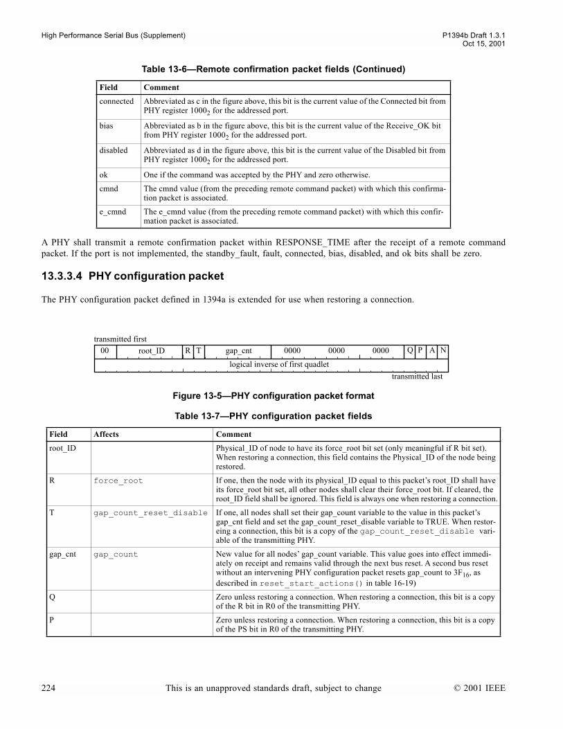
High Performance Serial Bus (Supplement) P1394b Draft 1.3.1Oct 15, 2001
A PHY shall transmit a remote confirmation packet within RESPONSE_TIME after the receipt of a remote commandpacket. If the port is not implemented, the standby_fault, fault, connected, bias, disabled, and ok bits shall be zero.
13.3.3.4 PHY configuration packet
The PHY configuration packet defined in 1394a is extended for use when restoring a connection.
connected Abbreviated as c in the figure above, this bit is the current value of the Connected bit from PHY register 10002 for the addressed port.
bias Abbreviated as b in the figure above, this bit is the current value of the Receive_OK bit from PHY register 10002 for the addressed port.
disabled Abbreviated as d in the figure above, this bit is the current value of the Disabled bit from PHY register 10002 for the addressed port.
ok One if the command was accepted by the PHY and zero otherwise.
cmnd The cmnd value (from the preceding remote command packet) with which this confirma-tion packet is associated.
e_cmnd The e_cmnd value (from the preceding remote command packet) with which this confir-mation packet is associated.
Figure 13-5PHY configuration packet format
Table 13-7PHY configuration packet fields
Field Affects Comment
root_ID Physical_ID of node to have its force_root bit set (only meaningful if R bit set). When restoring a connection, this field contains the Physical_ID of the node being restored.
R force_root If one, then the node with its physical_ID equal to this packets root_ID shall have its force_root bit set, all other nodes shall clear their force_root bit. If cleared, the root_ID field shall be ignored. This field is always one when restoring a connection.
T gap_count_reset_disable If one, all nodes shall set their gap_count variable to the value in this packets gap_cnt field and set the gap_count_reset_disable variable to TRUE. When restor-eing a connection, this bit is a copy of the gap_count_reset_disable vari-able of the transmitting PHY.
gap_cnt gap_count New value for all nodes gap_count variable. This value goes into effect immedi-ately on receipt and remains valid through the next bus reset. A second bus reset without an intervening PHY configuration packet resets gap_count to 3F16, as described in reset_start_actions() in table 16-19)
Q Zero unless restoring a connection. When restoring a connection, this bit is a copy of the R bit in R0 of the transmitting PHY.
P Zero unless restoring a connection. When restoring a connection, this bit is a copy of the PS bit in R0 of the transmitting PHY.
Table 13-6Remote confirmation packet fields (Continued)
Field Comment
transmitted last
root_ID00transmitted first
logical inverse of first quadlet
0000 0000 0000gap_cntR T NAPQ
224 This is an unapproved standards draft, subject to change © 2001 IEEE
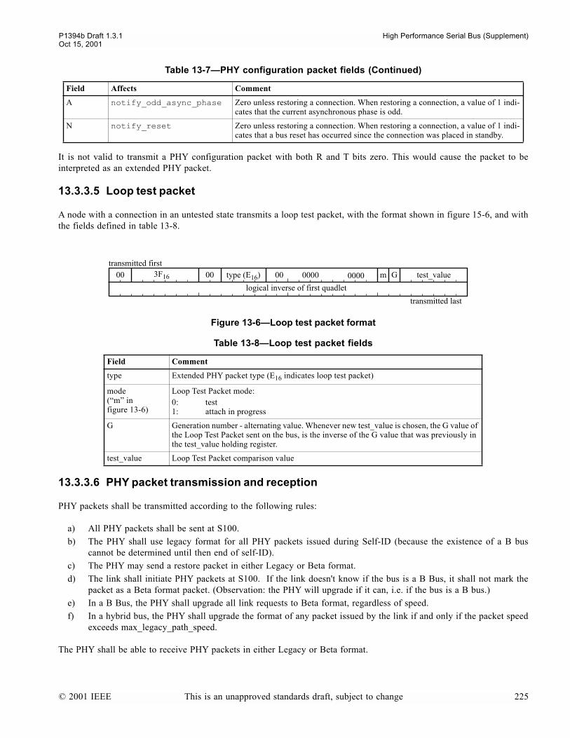
P1394b Draft 1.3.1 High Performance Serial Bus (Supplement)Oct 15, 2001
It is not valid to transmit a PHY configuration packet with both R and T bits zero. This would cause the packet to beinterpreted as an extended PHY packet.
13.3.3.5 Loop test packet
A node with a connection in an untested state transmits a loop test packet, with the format shown in figure 15-6, and withthe fields defined in table 13-8.
13.3.3.6 PHY packet transmission and reception
PHY packets shall be transmitted according to the following rules:
a) All PHY packets shall be sent at S100.b) The PHY shall use legacy format for all PHY packets issued during Self-ID (because the existence of a B bus
cannot be determined until then end of self-ID).c) The PHY may send a restore packet in either Legacy or Beta format.d) The link shall initiate PHY packets at S100. If the link doesn't know if the bus is a B Bus, it shall not mark the
packet as a Beta format packet. (Observation: the PHY will upgrade if it can, i.e. if the bus is a B bus.)e) In a B Bus, the PHY shall upgrade all link requests to Beta format, regardless of speed.f) In a hybrid bus, the PHY shall upgrade the format of any packet issued by the link if and only if the packet speed
exceeds max_legacy_path_speed.
The PHY shall be able to receive PHY packets in either Legacy or Beta format.
A notify_odd_async_phase Zero unless restoring a connection. When restoring a connection, a value of 1 indi-cates that the current asynchronous phase is odd.
N notify_reset Zero unless restoring a connection. When restoring a connection, a value of 1 indi-cates that a bus reset has occurred since the connection was placed in standby.
Figure 13-6Loop test packet format
Table 13-8Loop test packet fields
Field Comment
type Extended PHY packet type (E16 indicates loop test packet)
mode(m in figure 13-6)
Loop Test Packet mode:0: test1: attach in progress
G Generation number - alternating value. Whenever new test_value is chosen, the G value of the Loop Test Packet sent on the bus, is the inverse of the G value that was previously in the test_value holding register.
test_value Loop Test Packet comparison value
Table 13-7PHY configuration packet fields (Continued)
Field Affects Comment
transmitted last
3F1600transmitted first
logical inverse of first quadlet
type (E16) 00 test_value00 m G00000000
© 2001 IEEE This is an unapproved standards draft, subject to change 225
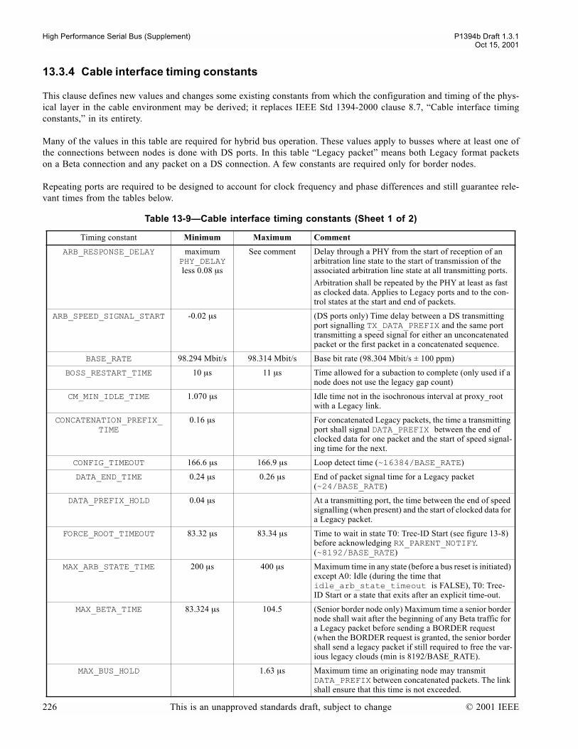
High Performance Serial Bus (Supplement) P1394b Draft 1.3.1Oct 15, 2001
13.3.4 Cable interface timing constants
This clause defines new values and changes some existing constants from which the configuration and timing of the phys-ical layer in the cable environment may be derived; it replaces IEEE Std 1394-2000 clause 8.7, Cable interface timingconstants, in its entirety.
Many of the values in this table are required for hybrid bus operation. These values apply to busses where at least one ofthe connections between nodes is done with DS ports. In this table Legacy packet means both Legacy format packetson a Beta connection and any packet on a DS connection. A few constants are required only for border nodes.
Repeating ports are required to be designed to account for clock frequency and phase differences and still guarantee rele-vant times from the tables below.
Table 13-9Cable interface timing constants (Sheet 1 of 2)
Timing constant Minimum Maximum Comment
ARB_RESPONSE_DELAY maximum PHY_DELAYless 0.08 µs
See comment Delay through a PHY from the start of reception of an arbitration line state to the start of transmission of the associated arbitration line state at all transmitting ports.
Arbitration shall be repeated by the PHY at least as fast as clocked data. Applies to Legacy ports and to the con-trol states at the start and end of packets.
ARB_SPEED_SIGNAL_START -0.02 µs (DS ports only) Time delay between a DS transmitting port signalling TX_DATA_PREFIX and the same port transmitting a speed signal for either an unconcatenated packet or the first packet in a concatenated sequence.
BASE_RATE 98.294 Mbit/s 98.314 Mbit/s Base bit rate (98.304 Mbit/s ± 100 ppm)
BOSS_RESTART_TIME 10 µs 11 µs Time allowed for a subaction to complete (only used if a node does not use the legacy gap count)
CM_MIN_IDLE_TIME 1.070 µs Idle time not in the isochronous interval at proxy_root with a Legacy link.
CONCATENATION_PREFIX_TIME
0.16 µs For concatenated Legacy packets, the time a transmitting port shall signal DATA_PREFIX between the end of clocked data for one packet and the start of speed signal-ing time for the next.
CONFIG_TIMEOUT 166.6 µs 166.9 µs Loop detect time (~16384/BASE_RATE)
DATA_END_TIME 0.24 µs 0.26 µs End of packet signal time for a Legacy packet (~24/BASE_RATE)
DATA_PREFIX_HOLD 0.04 µs At a transmitting port, the time between the end of speed signalling (when present) and the start of clocked data for a Legacy packet.
FORCE_ROOT_TIMEOUT 83.32 µs 83.34 µs Time to wait in state T0: Tree-ID Start (see figure 13-8) before acknowledging RX_PARENT_NOTIFY. (~8192/BASE_RATE)
MAX_ARB_STATE_TIME 200 µs 400 µs Maximum time in any state (before a bus reset is initiated) except A0: Idle (during the time that idle_arb_state_timeout is FALSE), T0: Tree-ID Start or a state that exits after an explicit time-out.
MAX_BETA_TIME 83.324 µs 104.5 (Senior border node only) Maximum time a senior border node shall wait after the beginning of any Beta traffic for a Legacy packet before sending a BORDER request (when the BORDER request is granted, the senior border shall send a legacy packet if still required to free the var-ious legacy clouds (min is 8192/BASE_RATE).
MAX_BUS_HOLD 1.63 µs Maximum time an originating node may transmit DATA_PREFIX between concatenated packets. The link shall ensure that this time is not exceeded.
226 This is an unapproved standards draft, subject to change © 2001 IEEE

P1394b Draft 1.3.1 High Performance Serial Bus (Supplement)Oct 15, 2001
13.4 Cable physical layer operation
The cable physical layer is defined in terms of state machines and C code definitions. The detailed operation is specifiedin terms of state machines given in sections 13.4.5 through 13.4.8, and a series of data structure definitions, constants,variables and routines given in clause 16.
MAX_DATA_TIME 84.34 µs The maximum time that clocked data may be transmitted continuously. If this limit is exceeded, unpredictable behavior may result.
MIN_DATA_PREFIX 0.14 µs The time a port transmitting a Legacy packet is required to signal DATA_PREFIX prior to clocked data for either an unconcatenated packet or the first packet in a concate-nated sequence.
MIN_DELETABLE_SYMBOL_TIME
0.04 µs Minimim time that an originating port is required to insert deletable symbols (~4/BASE_RATE)
MIN_IDLE_TIME 0.04 µs Minimum idle time (not including speed signalling on a Legacy mode port) after transmission of DATA_END for a Legacy packet at either an originating or repeating port (~4/BASE_RATE ).
MIN_PACKET_SEPARATION 0.34 µs Minimum time that an originating port is required to signal DATA_PREFIX between concatenated Legacy packets (~34/BASE_RATE)
NOMINAL_CYCLE_TIME 124.988 µs 125.013 µs Average time between the start of one isochronous period and the next (125 µs ± 100 ppm)
PHY_DELAY 0.06 µs if PHY_DELAY =
144ns - see description
See PHY registers Measured from the receipt of the first data bit to its retransmission by the repeating port(s) for all combina-tions of ports and speeds. Best-case repeater data delay has a fixed minimum. If PHY_DELAY is reported in the PHY registers as being greater than 144ns, then software may use the value (reported PHY_DELAY - reported JIT-TER) if this is greater.
RESET_TIME 166.6 µs 166.7 µs Reset hold time. (~16384/BASE_RATE)
RESET_WAIT 0.16 µs Reset wait delta time. (~16/BASE_RATE)
RESPONSE_TIME 0.04 µs PHY_DELAY+ 0.1 µs
1)Idle time at all ports of the responding node, measured at the cable connector, from the end of DATA_END or DATA_END that follows a PHY packet or primary packet to the start of the next arbitration line state, DATA_PREFIX, DISABLE_NOTIFY or SUSPEND. Applies to responding node.
2) Time between receipt of LTP value change and corre-sponding LTS transmit.
ROOT_CONTEND_FAST 1.60 µs 1.61 µs Time to wait in state T3: Root Contention if the random bit is zero, as described in clause 13.4.6. (~160/BASE_RATE)
ROOT_CONTEND_SLOW 3.20 µs 3.22 µs Time to wait in state T3: Root Contention if the random bit is one, as described in clause 13.4.6. (~320/BASE_RATE).
SHORT_RESET_TIME 1.26 µs 1.40 µs Short reset hold time. (~128/BASE_RATE)
SID_SPEED_SIGNAL_START -0.02 µs 0.02 µs (DS ports only). Time between a child DS port signalling TX_IDENT_DONE and the same port sending its speed capability signal.
SPEED_SIGNAL_LENGTH 0.10 µs 0.12 µs Duration of a valid Time that speed signal output is driven (~10/BASE_RATE) for Legacy packets.
Table 13-9Cable interface timing constants (Sheet 2 of 2)
Timing constant Minimum Maximum Comment
© 2001 IEEE This is an unapproved standards draft, subject to change 227
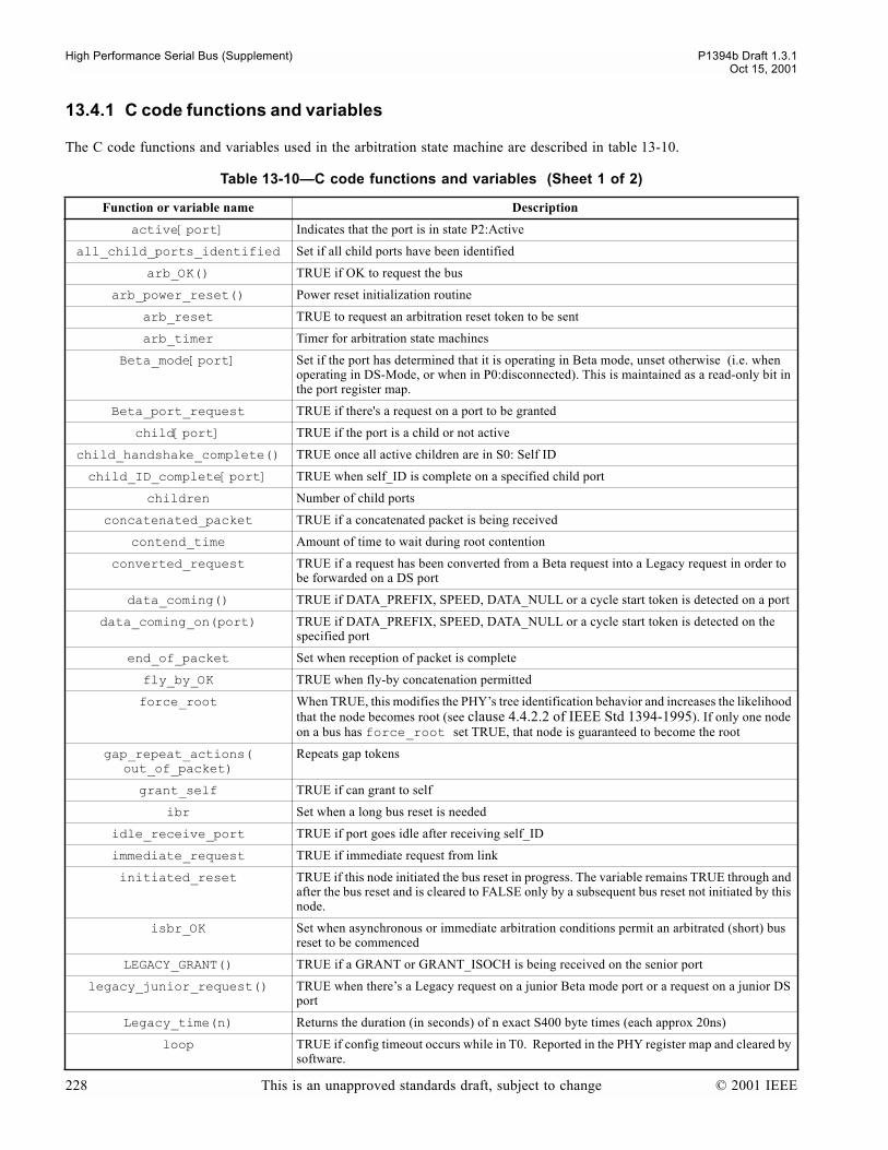
High Performance Serial Bus (Supplement) P1394b Draft 1.3.1Oct 15, 2001
13.4.1 C code functions and variables
The C code functions and variables used in the arbitration state machine are described in table 13-10.
Table 13-10C code functions and variables (Sheet 1 of 2)
Function or variable name Description
active[port] Indicates that the port is in state P2:Active
all_child_ports_identified Set if all child ports have been identified
arb_OK() TRUE if OK to request the bus
arb_power_reset() Power reset initialization routine
arb_reset TRUE to request an arbitration reset token to be sent
arb_timer Timer for arbitration state machines
Beta_mode[port] Set if the port has determined that it is operating in Beta mode, unset otherwise (i.e. when operating in DS-Mode, or when in P0:disconnected). This is maintained as a read-only bit in the port register map.
Beta_port_request TRUE if there's a request on a port to be granted
child[port] TRUE if the port is a child or not active
child_handshake_complete() TRUE once all active children are in S0: Self ID
child_ID_complete[port] TRUE when self_ID is complete on a specified child port
children Number of child ports
concatenated_packet TRUE if a concatenated packet is being received
contend_time Amount of time to wait during root contention
converted_request TRUE if a request has been converted from a Beta request into a Legacy request in order to be forwarded on a DS port
data_coming() TRUE if DATA_PREFIX, SPEED, DATA_NULL or a cycle start token is detected on a port
data_coming_on(port) TRUE if DATA_PREFIX, SPEED, DATA_NULL or a cycle start token is detected on the specified port
end_of_packet Set when reception of packet is complete
fly_by_OK TRUE when fly-by concatenation permitted
force_root When TRUE, this modifies the PHYs tree identification behavior and increases the likelihood that the node becomes root (see clause 4.4.2.2 of IEEE Std 1394-1995). If only one node on a bus has force_root set TRUE, that node is guaranteed to become the root
gap_repeat_actions(out_of_packet)
Repeats gap tokens
grant_self TRUE if can grant to self
ibr Set when a long bus reset is needed
idle_receive_port TRUE if port goes idle after receiving self_ID
immediate_request TRUE if immediate request from link
initiated_reset TRUE if this node initiated the bus reset in progress. The variable remains TRUE through and after the bus reset and is cleared to FALSE only by a subsequent bus reset not initiated by this node.
isbr_OK Set when asynchronous or immediate arbitration conditions permit an arbitrated (short) bus reset to be commenced
LEGACY_GRANT() TRUE if a GRANT or GRANT_ISOCH is being received on the senior port
legacy_junior_request() TRUE when theres a Legacy request on a junior Beta mode port or a request on a junior DS port
Legacy_time(n) Returns the duration (in seconds) of n exact S400 byte times (each approx 20ns)
loop TRUE if config timeout occurs while in T0. Reported in the PHY register map and cleared by software.
228 This is an unapproved standards draft, subject to change © 2001 IEEE
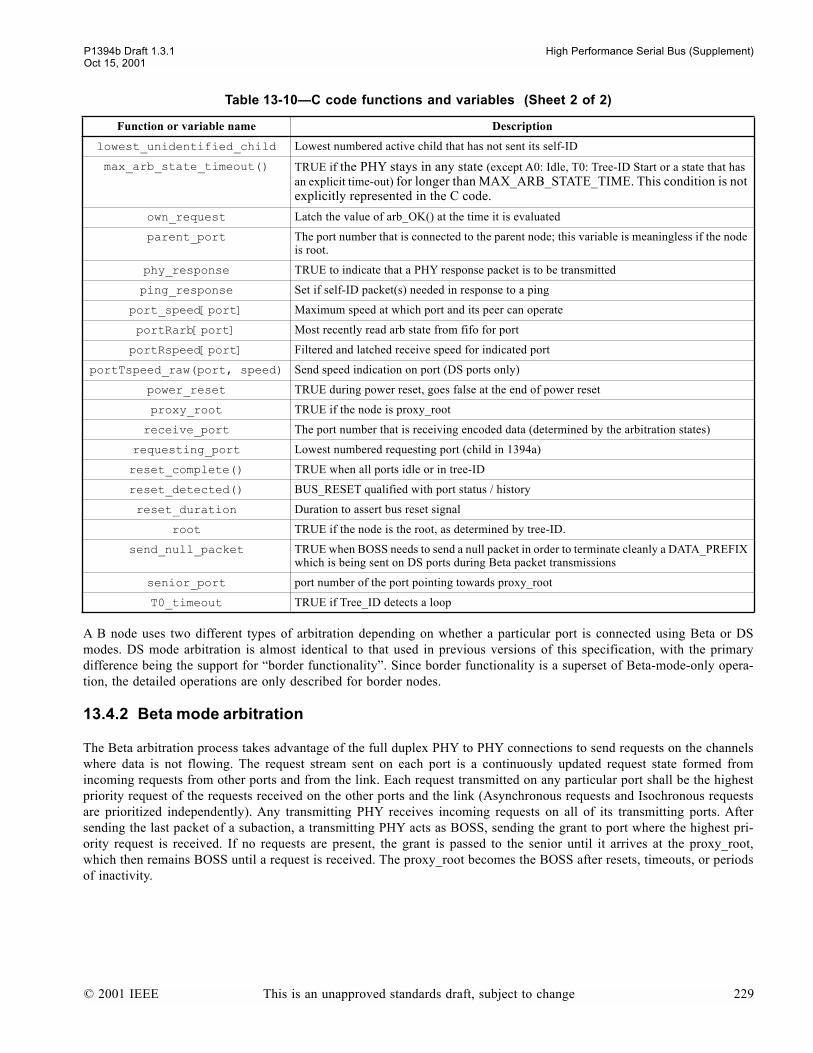
P1394b Draft 1.3.1 High Performance Serial Bus (Supplement)Oct 15, 2001
A B node uses two different types of arbitration depending on whether a particular port is connected using Beta or DSmodes. DS mode arbitration is almost identical to that used in previous versions of this specification, with the primarydifference being the support for border functionality. Since border functionality is a superset of Beta-mode-only opera-tion, the detailed operations are only described for border nodes.
13.4.2 Beta mode arbitration
The Beta arbitration process takes advantage of the full duplex PHY to PHY connections to send requests on the channelswhere data is not flowing. The request stream sent on each port is a continuously updated request state formed fromincoming requests from other ports and from the link. Each request transmitted on any particular port shall be the highestpriority request of the requests received on the other ports and the link (Asynchronous requests and Isochronous requestsare prioritized independently). Any transmitting PHY receives incoming requests on all of its transmitting ports. Aftersending the last packet of a subaction, a transmitting PHY acts as BOSS, sending the grant to port where the highest pri-ority request is received. If no requests are present, the grant is passed to the senior until it arrives at the proxy_root,which then remains BOSS until a request is received. The proxy_root becomes the BOSS after resets, timeouts, or periodsof inactivity.
lowest_unidentified_child Lowest numbered active child that has not sent its self-ID
max_arb_state_timeout() TRUE if the PHY stays in any state (except A0: Idle, T0: Tree-ID Start or a state that has an explicit time-out) for longer than MAX_ARB_STATE_TIME. This condition is not explicitly represented in the C code.
own_request Latch the value of arb_OK() at the time it is evaluated
parent_port The port number that is connected to the parent node; this variable is meaningless if the node is root.
phy_response TRUE to indicate that a PHY response packet is to be transmitted
ping_response Set if self-ID packet(s) needed in response to a ping
port_speed[port] Maximum speed at which port and its peer can operate
portRarb[port] Most recently read arb state from fifo for port
portRspeed[port] Filtered and latched receive speed for indicated port
portTspeed_raw(port, speed) Send speed indication on port (DS ports only)
power_reset TRUE during power reset, goes false at the end of power reset
proxy_root TRUE if the node is proxy_root
receive_port The port number that is receiving encoded data (determined by the arbitration states)
requesting_port Lowest numbered requesting port (child in 1394a)
reset_complete() TRUE when all ports idle or in tree-ID
reset_detected() BUS_RESET qualified with port status / history
reset_duration Duration to assert bus reset signal
root TRUE if the node is the root, as determined by tree-ID.
send_null_packet TRUE when BOSS needs to send a null packet in order to terminate cleanly a DATA_PREFIX which is being sent on DS ports during Beta packet transmissions
senior_port port number of the port pointing towards proxy_root
T0_timeout TRUE if Tree_ID detects a loop
Table 13-10C code functions and variables (Sheet 2 of 2)
Function or variable name Description
© 2001 IEEE This is an unapproved standards draft, subject to change 229
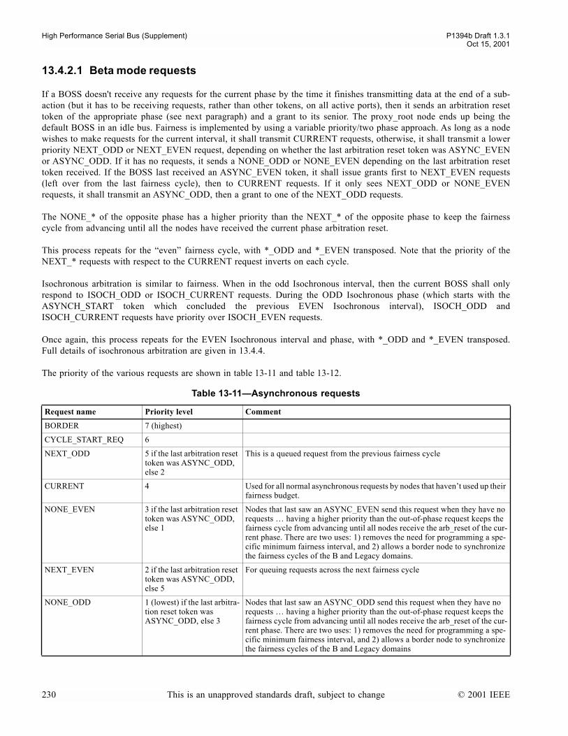
High Performance Serial Bus (Supplement) P1394b Draft 1.3.1Oct 15, 2001
13.4.2.1 Beta mode requests
If a BOSS doesn't receive any requests for the current phase by the time it finishes transmitting data at the end of a sub-action (but it has to be receiving requests, rather than other tokens, on all active ports), then it sends an arbitration resettoken of the appropriate phase (see next paragraph) and a grant to its senior. The proxy_root node ends up being thedefault BOSS in an idle bus. Fairness is implemented by using a variable priority/two phase approach. As long as a nodewishes to make requests for the current interval, it shall transmit CURRENT requests, otherwise, it shall transmit a lowerpriority NEXT_ODD or NEXT_EVEN request, depending on whether the last arbitration reset token was ASYNC_EVENor ASYNC_ODD. If it has no requests, it sends a NONE_ODD or NONE_EVEN depending on the last arbitration resettoken received. If the BOSS last received an ASYNC_EVEN token, it shall issue grants first to NEXT_EVEN requests(left over from the last fairness cycle), then to CURRENT requests. If it only sees NEXT_ODD or NONE_EVENrequests, it shall transmit an ASYNC_ODD, then a grant to one of the NEXT_ODD requests.
The NONE_* of the opposite phase has a higher priority than the NEXT_* of the opposite phase to keep the fairnesscycle from advancing until all the nodes have received the current phase arbitration reset.
This process repeats for the even fairness cycle, with *_ODD and *_EVEN transposed. Note that the priority of theNEXT_* requests with respect to the CURRENT request inverts on each cycle.
Isochronous arbitration is similar to fairness. When in the odd Isochronous interval, then the current BOSS shall onlyrespond to ISOCH_ODD or ISOCH_CURRENT requests. During the ODD Isochronous phase (which starts with theASYNCH_START token which concluded the previous EVEN Isochronous interval), ISOCH_ODD andISOCH_CURRENT requests have priority over ISOCH_EVEN requests.
Once again, this process repeats for the EVEN Isochronous interval and phase, with *_ODD and *_EVEN transposed.Full details of isochronous arbitration are given in 13.4.4.
The priority of the various requests are shown in table 13-11 and table 13-12.
Table 13-11Asynchronous requests
Request name Priority level Comment
BORDER 7 (highest)
CYCLE_START_REQ 6
NEXT_ODD 5 if the last arbitration reset token was ASYNC_ODD, else 2
This is a queued request from the previous fairness cycle
CURRENT 4 Used for all normal asynchronous requests by nodes that havent used up their fairness budget.
NONE_EVEN 3 if the last arbitration reset token was ASYNC_ODD, else 1
Nodes that last saw an ASYNC_EVEN send this request when they have no requests having a higher priority than the out-of-phase request keeps the fairness cycle from advancing until all nodes receive the arb_reset of the cur-rent phase. There are two uses: 1) removes the need for programming a spe-cific minimum fairness interval, and 2) allows a border node to synchronize the fairness cycles of the B and Legacy domains.
NEXT_EVEN 2 if the last arbitration reset token was ASYNC_ODD, else 5
For queuing requests across the next fairness cycle
NONE_ODD 1 (lowest) if the last arbitra-tion reset token was ASYNC_ODD, else 3
Nodes that last saw an ASYNC_ODD send this request when they have no requests having a higher priority than the out-of-phase request keeps the fairness cycle from advancing until all nodes receive the arb_reset of the cur-rent phase. There are two uses: 1) removes the need for programming a spe-cific minimum fairness interval, and 2) allows a border node to synchronize the fairness cycles of the B and Legacy domains
230 This is an unapproved standards draft, subject to change © 2001 IEEE
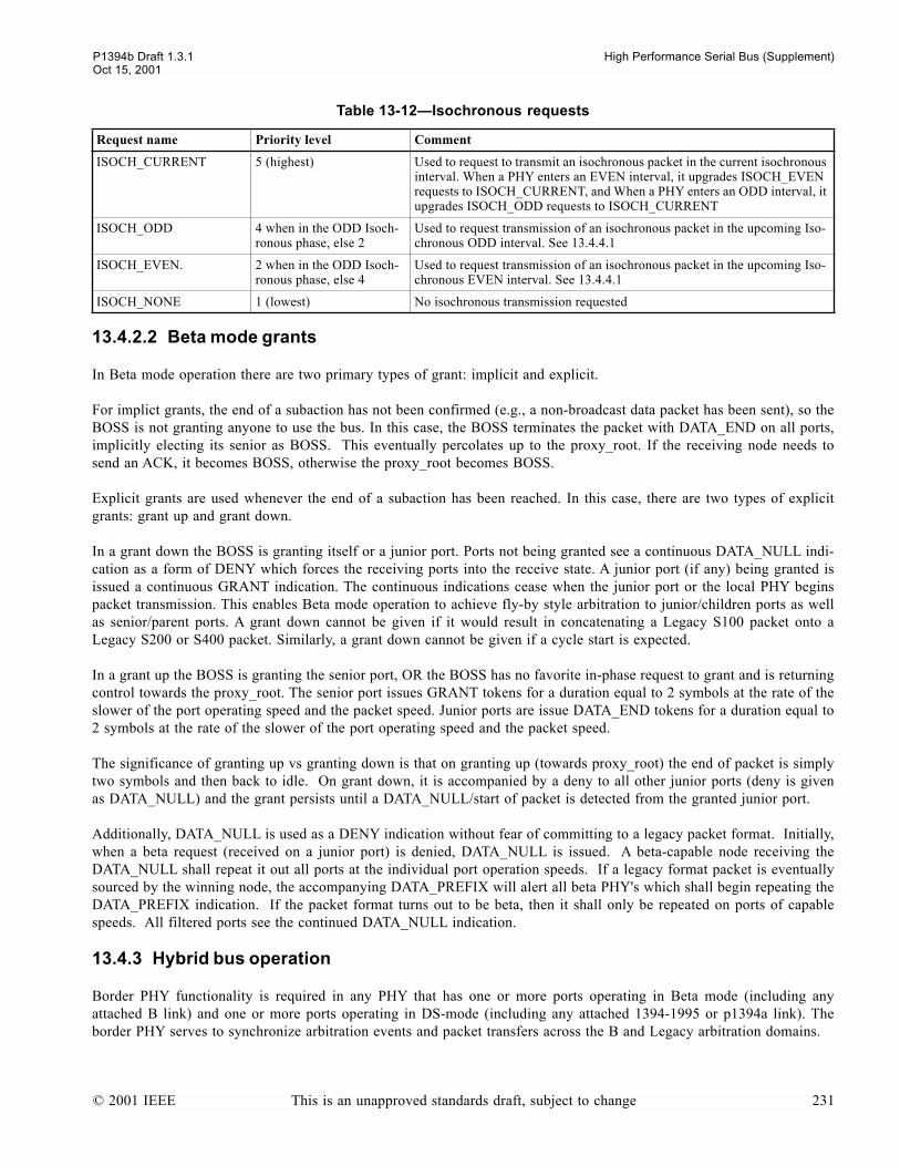
P1394b Draft 1.3.1 High Performance Serial Bus (Supplement)Oct 15, 2001
13.4.2.2 Beta mode grants
In Beta mode operation there are two primary types of grant: implicit and explicit.
For implict grants, the end of a subaction has not been confirmed (e.g., a non-broadcast data packet has been sent), so theBOSS is not granting anyone to use the bus. In this case, the BOSS terminates the packet with DATA_END on all ports,implicitly electing its senior as BOSS. This eventually percolates up to the proxy_root. If the receiving node needs tosend an ACK, it becomes BOSS, otherwise the proxy_root becomes BOSS.
Explicit grants are used whenever the end of a subaction has been reached. In this case, there are two types of explicitgrants: grant up and grant down.
In a grant down the BOSS is granting itself or a junior port. Ports not being granted see a continuous DATA_NULL indi-cation as a form of DENY which forces the receiving ports into the receive state. A junior port (if any) being granted isissued a continuous GRANT indication. The continuous indications cease when the junior port or the local PHY beginspacket transmission. This enables Beta mode operation to achieve fly-by style arbitration to junior/children ports as wellas senior/parent ports. A grant down cannot be given if it would result in concatenating a Legacy S100 packet onto aLegacy S200 or S400 packet. Similarly, a grant down cannot be given if a cycle start is expected.
In a grant up the BOSS is granting the senior port, OR the BOSS has no favorite in-phase request to grant and is returningcontrol towards the proxy_root. The senior port issues GRANT tokens for a duration equal to 2 symbols at the rate of theslower of the port operating speed and the packet speed. Junior ports are issue DATA_END tokens for a duration equal to2 symbols at the rate of the slower of the port operating speed and the packet speed.
The significance of granting up vs granting down is that on granting up (towards proxy_root) the end of packet is simplytwo symbols and then back to idle. On grant down, it is accompanied by a deny to all other junior ports (deny is givenas DATA_NULL) and the grant persists until a DATA_NULL/start of packet is detected from the granted junior port.
Additionally, DATA_NULL is used as a DENY indication without fear of committing to a legacy packet format. Initially,when a beta request (received on a junior port) is denied, DATA_NULL is issued. A beta-capable node receiving theDATA_NULL shall repeat it out all ports at the individual port operation speeds. If a legacy format packet is eventuallysourced by the winning node, the accompanying DATA_PREFIX will alert all beta PHY's which shall begin repeating theDATA_PREFIX indication. If the packet format turns out to be beta, then it shall only be repeated on ports of capablespeeds. All filtered ports see the continued DATA_NULL indication.
13.4.3 Hybrid bus operation
Border PHY functionality is required in any PHY that has one or more ports operating in Beta mode (including anyattached B link) and one or more ports operating in DS-mode (including any attached 1394-1995 or p1394a link). Theborder PHY serves to synchronize arbitration events and packet transfers across the B and Legacy arbitration domains.
Table 13-12Isochronous requests
Request name Priority level Comment
ISOCH_CURRENT 5 (highest) Used to request to transmit an isochronous packet in the current isochronous interval. When a PHY enters an EVEN interval, it upgrades ISOCH_EVEN requests to ISOCH_CURRENT, and When a PHY enters an ODD interval, it upgrades ISOCH_ODD requests to ISOCH_CURRENT
ISOCH_ODD 4 when in the ODD Isoch-ronous phase, else 2
Used to request transmission of an isochronous packet in the upcoming Iso-chronous ODD interval. See 13.4.4.1
ISOCH_EVEN. 2 when in the ODD Isoch-ronous phase, else 4
Used to request transmission of an isochronous packet in the upcoming Iso-chronous EVEN interval. See 13.4.4.1
ISOCH_NONE 1 (lowest) No isochronous transmission requested
© 2001 IEEE This is an unapproved standards draft, subject to change 231
High Performance Serial Bus (Supplement) P1394b Draft 1.3.1Oct 15, 2001
13.4.3.1 Hybrid bus initialization
A B PHY shall send its self_ID packet at S100, in Legacy format and timing, and with a speed code. (Note that a PHYwith a Legacy link shall send out its self_ID packet at S100, in Legacy format and timing, without a speed code, even ifthe link is inactive and all the ports are operating in Beta mode). A border node repeats self_ID packets received from aDS port without a speed code. Self-ID packets are forwarded with/without speed code as received.
A node shall use the receipt of self_ID packets without speed code to determine the maximum speed of legacy connec-tions (max_Legacy_path_speed) on the bus, and, when originating packets on the bus, shall upgrade packets transmittedat speeds higher than max_Legacy_path_speed to Beta format. If a node has a Legacy link (whether or not active), it shallset max_Legacy_path_speed to S400.
During the self_ID process, a border shall assume that it is senior border unless it receives a self_ID packet without speedcode from a senior port operating in Beta mode. Note that this will happen after the local node has completed transmis-sion of its self_ID sequence and entered A0:Idle. A senior border shall determine that it is proxy_root if it is root or if itsparent port is operating in Beta Mode. This process guarantees that a proxy_root is always a border node if the root is ina B cloud. This is necessary since a hybrid bus has gap timing considerations that are only guaranteed by a border-capableor legacy PHY.
13.4.3.2 Border node functions
A border PHY by design addresses three important differences between Beta and Legacy arbitration:
a) Synchronization of gap events: Legacy arbitration marks the end of the isochronous period and the fairness periodwith periods of IDLE time known as subaction gaps and arbitration reset gaps, respectively. Beta arbitrationmarks the same events with the appropriate usage of the tokens ASYNC_EVEN/ODD. A border node keeps thearbitration domains synchronized by forcing a 1:1 correspondence of elapsed gap times to gap tokens. Thisensures that the programming model (isochronous batched before asynchronous, etc.) is consistent regardless ofthe bus access methods used on the physical media.
b) Protection of Legacy Quiet Windows: Legacy arbitration has two quiet windows during which the bus isrequired to remain IDLE for consistent bus-wide detection of specific gap events. To mark the end of theisochronous interval or to indicate a missing acknowledge, asynchronous arbitration cannot begin sooner than asubaction_gap + arb_delay after the bus last went IDLE. To mark the end of a fairness interval, asynchronousarbitration is again prohibited until an arb_reset_gap + arb_delay after the bus last went IDLE. Border nodes actto enforce these quiet windows without requiring B only nodes to implement gap based timers.
c) Start of isochronous interval: All PHYs within the B cloud containing the cycle master can know the isochronousinterval has begun when the cycle master transmits a CYCLE_START_ODD/EVEN token. However, in B cloudsnot containing the cycle master, not all PHYs are able to detect the start of the isochronous interval; only PHYswith isochronous capable Beta links can track the isochronous interval and phase. The mechanism therefore has toallow other PHYs to forward requests and route grants correctly in the absence of CYCLE_START_ODD/EVENtokens from the cycle master.
13.4.3.2.1 Synchronization of gap events
In an effort to synchronize Legacy gap indications with Beta token indications:
a) Legacy clouds are prevented from timing gaps during Beta-only transmissionsb) B-only nodes are prevented from issuing gap tokens in a hybrid network (since they dont know about Legacy gap
timings)c) Border PHYs shall guarantee a gap token is generated whenever a corresponding gap period has expired within
the Legacy cloud and, by extension, in all Legacy clouds connected to the bus
232 This is an unapproved standards draft, subject to change © 2001 IEEE
P1394b Draft 1.3.1 High Performance Serial Bus (Supplement)Oct 15, 2001
13.4.3.2.1.1 Preventing timing of gaps during packet transmission
Particularly during Beta-only traffic, border nodes need to ensure that Legacy devices dont detect any gaps. For example,during isochronous transmission of Beta-only packets, an occurrence of a subaction gap in the Legacy cloud would causeLegacy nodes to fall into the asynchronous period too quickly and perhaps before their own isochronous transmissionsoccurred. As such:
a) Legacy formatted packets are repeated by a border PHY directly to any DS ports as normal (with DATA_PREFIXreplacing the payload if the packet speed is greater than the peers capability).
b) For Beta formatted packets, a border shall begin generating DATA_PREFIX on its DS ports. Because the bordernode meets minimum DATA_PREFIX/DATA_END timings and cannot predict when the next Legacy formattedpacket will arrive, it cannot safely release DATA_PREFIX until such a packet arrives. The Legacy packet isconcatenated onto the DATA_PREFIX and is received normally by Legacy devices.
c) In order to prevent Legacy nodes from staying in RX for longer than their arbitration state timeout, the BOSS ina B cloud shall issue a Legacy null-packet whenever the end of a subaction has been reached, there are no morein-phase requests pending, and the last packet sent was not a Legacy formatted packet. In addition, the SeniorBorder shall issue a BORDER request if the bus has been generating beta format packets for MAX_BETA_TIMEand, when granted, issue a Legacy null packet if still required.
13.4.3.2.1.2 Preventing B-Only PHYs from issuing gap tokens
Normally, a B-only PHY will issue a gap token at the end of a subaction when no eligible in-phase requests remain to begranted. However, a B-only PHY shall not issue a gap token in a hybrid network (since B-only PHYs dont have gapcounts and timers). To implement this, all PHYs detect the presence of a hybrid bus during self_ID, and in this case, if atthe end of a subaction the BOSS has no more in-phase requests to grant, it passes control towards the proxy_root (aftertransmitting any necessary null packet to free the border nodes stuck in DATA_PREFIX). No gap token is issued andthe bus will fall IDLE.
13.4.3.2.1.3 Guaranteeing legacy gaps are matched with tokens
The senior border in each B cloud is responsible for ensuring that the Legacy gap timings are observed, and is the onlyPHY within the cloud allowed to issue ASYNC_EVEN/ODD tokens. In order to synchronize Legacy gap indications withBOSS token indications, the senior border shall issue an ASYNC_EVEN/ODD token of the current phase whenever ittimes a subaction idle gap and shall issue an ASYNC_EVEN/ODD token of the new phase whenever it times an arb-resetidle gap. The senior border shall continue to issue tokens of the current phase so long as the bus is idle.
13.4.3.2.2 Protection of legacy quiet windows
In a hybrid bus, the subaction indication which follows at the end of an isochronous period or signifies a missingacknowledge is required to be consistently detected bus-wide. This requires observance of the quiet time in Legacyarbitration leading up to the subaction gap. The quiet period is at risk if ACK packets arrive late, if isochronous arbitra-tion is granted late, or primary asynchronous packet arbitration starts too quickly.
Similarly, the indication which follows at the end of a fairness interval is required to be consistently detected bus-wide.This requires observance of the second quiet time in Legacy arbitration which begins an arb_delay following a sub-action gap when arbitration is momentarily allowed and extends until after an arbitration reset gap is detected. This quietperiod is at risk if a late arriving asynchronous request is granted, or if arbitration for the next fairness interval is grantedtoo soon.
All nodes (including B-only) are required to meet RESPONSE_TIME and ARB_RESPONSE_DELAY, meaning dataprefix or arbitration is required to be initiated by a responding node and repeated by intermediate nodes within 1394a-2000 defined limits. The 1394a-2000 gap count analysis then applies and guarantees that ACK packets and isochronousarbitration will be seen by all nodes before the beginning of the first quiet interval.
© 2001 IEEE This is an unapproved standards draft, subject to change 233
High Performance Serial Bus (Supplement) P1394b Draft 1.3.1Oct 15, 2001
After transmitting a packet that marks the end of a subaction, the current BOSS shall grant the next PHY immediately. Ifthere are no valid requests to grant, control is passed towards the proxy_root.
In response to Beta arbitration requests, the senior border shall begin arbitration for the bus in accordance with theLegacy rules for initiating arbitration so as to ensure consistent bus-wide detection of gaps. A grant may be issued (ifproxy_root) or arbitration on the DS mode parent port may begin:
a) up to arb_delay following the issuance of an ASYNC_EVEN/ODD token of the current phase provided theprevious packet represented the end of a subaction (ACK-accelerated arbitration),
b) at arb_delay following the issuance of an ASYNC_EVEN/ODD token of the current phase,c) anytime after the arb_delay following the issuance of an ASYNC_EVEN/ODD token to advance the phase, or d) within ARB_RESPONSE_DELAY after receiving a LEGACY_REQUEST1 or ISOCH_CURRENT2 request
In addition, a proxy-root can issue a grant within RESPONSE_TIME of becoming BOSS.
13.4.3.2.3 BOSS PHYs unaware of isochronous interval
The BOSS PHY normally uses the current bus phase (asynchronous/isochronous) to determine which of the arbitrationrequests it is receiving are in phase and are eligible to be granted. However, in B clouds not containing the cycle master,not all PHYs are able to detect the start of the isochronous interval, only PHYs with isochronous capable Beta links cantrack the isochronous interval and phase. The mechanism therefore allows other PHYs to forward requests and routegrants correctly in the absence of CYCLE_START_ODD/EVEN tokens from the cycle master.
To make sure that isochronous requests can be granted properly in the absence any interval information from the cyclemaster, LEGACY_REQUEST and ISOCH_CURRENT requests are used.
The LEGACY_REQUEST and ISOCH_CURRENT requests have priority over other asynchronous or isochronousrequests and communicate to the BOSS PHY that the originator of the request has enough information to determine thatit would be appropriate and valid to immediately grant the request.
To allow a node to route a grant unambiguously in the absence of bus interval information, a GRANT_ISOCH token isused.
13.4.3.3 Border Request Mapping
13.4.3.3.1 Legacy to Beta
RX_REQUEST from Legacy (only heard between active packet transfers) is mapped to new Beta LEGACY_REQUESTimmediately. Note that the border PHY may not know the phase of the bus (isochronous or asynchronous), so it cannotgenerally try to map RX_REQUEST to a Beta asynchronous or isochronous request type.
Unlike other BOSS request types, the LEGACY_REQUEST operates like it does in 1394a-2000 and is expected to bewithdrawn if denied.
13.4.3.3.2 Beta to Legacy
A senior border node always respects the 1394a quiet times when forwarding eligible Beta requests into the Legacy cloud(see 13.4.3.2.2). All requests are forwarded as TX_REQUESTs.
1 Border nodes forward Legacy style requests as high priority LEGACY_REQUESTs. Given that all Legacy nodes respect the quiet timeswhen generating a LEGACY_REQUEST, and given that B-nodes repeat Legacy requests within ARB_RESPONSE_DELAY,LEGACY_REQUESTs can only be present outside of quiet times.
2 ISOCH_CURRENT requests obey the same timing as IsoReq requests in 1394a, and therefore can only be present outside quiet times.
234 This is an unapproved standards draft, subject to change © 2001 IEEE
P1394b Draft 1.3.1 High Performance Serial Bus (Supplement)Oct 15, 2001
13.4.3.4 Discussion of Root outside the B cloud
Of special interest is the case in which the root resides behind a border (root is either a Legacy node or in a more seniorB cloud). The senior border will arbitrate for the bus on behalf of the B cloud. Once arbitration is won, the senior borderis BOSS and can introduce a grant into the B cloud. After the first packet is sent, the current BOSS can either grant thenext PHY, grant the senior explicitly (indicating that the end of a subaction was reached), or implicitly grant the senior(indicating that this may not be the end of a subaction). For as long as control can remain in the B cloud, the senior bordershall drive DATA_PREFIX into the Legacy domain. If the end of a subaction is not reached, control will naturally passback to the senior border and into the Legacy domain.
It is necessary to ensure that the B cloud concatenations dont risk cycle start starvation. Accordingly, the BOSS shallrefrain from passing a grant received from a junior port to either a link or another junior port when
a) the bus is in asynch phase, andb) the cycle master is outside the beta cloud, andc) a cycle start is expected. If cycle start indications are not available from the local link, then cycle start is
permanently considered to be expected
If the cycle master is a legacy link, then on entry to A0:Idle, the PHY shall wait for CM_MIN_IDLE_TIME to allow suf-ficient idle time in case the link needs to request the bus in order to transmit a cycle start packet.
13.4.4 Isochronous intervals
Cycle start tokens (CYCLE_START_ODD or CYCLE_START_EVEN) are only launched once per interval by a Betacycle master (if any) for the purpose of confirming the phase (even/odd) of the upcoming isochronous interval and to helpnaked PHY's in the senior Beta cloud track pipelined phases.
B PHY's only enter the isochronous interval when either the attached link (if any) indicates a cycle start packet has beenreceived (like 1394a) or a cycle start token is received. B links intending to perform isochronous transactions alwaysreport cycle start packets to their PHYs as well as their interpreted phase of the interval.
The isochronous interval at a given PHY/link pair concludes with receipt/generation of an ASYNC_EVEN/ODD.
Isochronous phases (even vs. odd) increment with the ASYNC_EVEN/ODD concluding an isochronous interval.
In senior Beta clouds (B clouds that contain the proxy_root and cycle master), isochronous phasing (even vs. odd) is syn-chronized between all links and PHYs in the cloud. In junior B clouds (B clouds that do not contain the proxy_root andcycle master), the phasing is maintained pair wise between links and PHYs. No attempt is made to keep the entire cloudsynchronized to the same phase.
ISOCH_ODD/EVEN requests are used between all links and PHYs and additionally on the serial bus in the senior Bcloud. They are not used on the serial bus in junior B clouds. Their primary purpose is to speed up routing of isochronousgrants after a cycle start packet has been launched.
ISOCH_CURRENT is used in B buses as a robust way of recovering from phase synchronization errors. Additionally,ISOCH_CURRENT replaces cycle start tokens in junior B clouds as the primary mechanism of forcing naked senior bor-ders to request the bus on behalf of a Beta isochronous talker.
GRANT_ISOCH is used to differentiate between grants intended for isochronous transmissions and grants intended forasynchronous transmissions. If GRANT_ISOCH arrives at the senior port of a PHY which can't use it or forward it on,then a null packet with a quiet grant is generated as a way of releasing the bus.
© 2001 IEEE This is an unapproved standards draft, subject to change 235
High Performance Serial Bus (Supplement) P1394b Draft 1.3.1Oct 15, 2001
13.4.4.1 Isochronous interval rules
a) A Beta cycle master (a cycle master with a B link and a B PHY) shall begin an isochronous interval by launchinga cycle start token then a cycle start packet and then either a GRANT_ISOCH or a DATA_NULL. A Legacy cyclemaster, of course, will start the interval with only a cycle start packet. Only the cycle master can originate thecycle start token and then only at the start of the interval. There will never be a second cycle start token within thesame interval under any circumstance. Note that cycle start tokens never appear in junior B clouds since there isno Beta cycle master in such clouds. The cycle start token is launched for an S100 symbol time to make sure itcan be delivered everywhere and safely repeated at the start of a packet.
b) Cycle start tokens are repeated by B PHY's while in the RX : Receive state. At this time, they are also copied toa local B link, if any. A PHY which receives a cycle start token in IDLE shall transition to RX (just as whenreceiving SPEED, DATA_PREFIX, or DATA_NULL.)
c) Whenever a cycle start packet is decoded by a link capable of making an isochronous request, the link shall notifythe PHY such that the PHY can launch an arbitration wavefront within RESPONSE_TIME. This is so that thearbitration request will reach the cycle master before a subaction gap appears anywhere. The cycle startnotification (PH_CYCLE_START_ODD or PH_CYCLE_START_EVEN) to the PHY also indicates whichisochronous phase the link thinks has started with the arrival of the cycle start packet. Links that don't doisochronous or don't have any scheduled isochronous packets aren't required to send the cycle start packetindication.
d) A PHY first becomes aware of the isochronous interval at the first of two possible events: a) the arrival of a cyclestart token, or b) the cycle start notification from a local link.
e) An arriving cycle start token at a PHY is always used to update the isochronous phase to that indicated in thecycle start token. If the isochronous interval begins in a PHY because of a cycle start notification from the link,then the PHY updates its isochronous phase to that indicated in that notification.
f) When a PHY becomes aware that it is in the isochronous interval, it shall upgrade in-phase isochronousrequests from it's local link to ISOCH_CURRENT. ISOCH_CURRENT has the highest isochronous priority.
g) A link first becomes aware of the isochronous interval at the first of two possible events: a) the arrival of a cyclestart token, or b) the arrival of a cycle start packet. Note that it is possible for the link to transmit isochronouswithout having received a valid cycle start packet.
h) An arriving cycle start token at the link is always used to update the isochronous phase to the phase indicated inthe cycle start token. If the isochronous interval began in the link because of item b) immediately above then thelink infers the loss/lack of a cycle start token as it enters the isochronous interval. The link's perceived phase isalways delivered to the PHY in the cycle start notification to help keep the link and PHY synchronized. Note thatthis means the link is required to internally track isochronous phases.
i) The isochronous interval ends at each PHY and link with arrival/generation of an ASYNC_EVEN/ODD j) The isochronous phase (even vs. odd) is reset to the even phase with each bus reset. The phase is inverted with the
ASYNC_EVEN/ODD that ends the isochronous interval. As such, the phase indication describes the phase of theupcoming isochronous interval or the current isochronous interval in progress. As noted above, the phaseinformation in a cycle start token or from a link's indication of a cycle start packet when a cycle start token ismissing is used to confirm the phase. Both links and PHYs track the phase by observing cycle start token/cyclestart packet and ASYNC_EVEN/ODD.
k) The link makes either ISOCH_EVEN or ISOCH_ODD requests to its PHY in a pipelined fashion. ISOCH_EVENrequests for an EVEN interval may be issued after the end of the previous EVEN isochronous interval (markedwith an ASYNC_EVEN/ODDas the phase changes to ODD). A request for the EVEN interval made before theEVEN interval shall be issued sufficiently early that it is pending at the cycle master before the end of the cyclestart packet for the EVEN isochronous interval is sent. Any subsequent requests for the EVEN interval madewithin the interval shall be issued within RESPONSE_TIME after the end of transmission of a previousisochronous packet for a hybrid bus, and shall be issued using the MORE cycle for a B-bus. Similar rules applyfor the ODD interval.
l) When a given PHY is outside of its isochronous interval, the only valid isochronous requests it can generate areISOCH_EVEN, ISOCH_ODD, and ISOCH_NONE. They are forwarded with the usual priority, based on thephase of the upcoming interval. For junior B clouds, ISOCH_EVEN and ISOCH_ODD requests are not used onthe cable and expressly forbidden from appearing on the serial bus.
236 This is an unapproved standards draft, subject to change © 2001 IEEE
P1394b Draft 1.3.1 High Performance Serial Bus (Supplement)Oct 15, 2001
m) A PHY shall unconditionally use a received GRANT_ISOCH to exit the LEGACY_REQUEST state (sendTX_GRANT to junior DS port or grant Legacy link) or to service any in-phase isochronous requests receivedfrom the link or cable ports. If unable to use the grant, the GRANT_ISOCH is first used to unlock DS ports inthe network, and then forwarded or returned to the senior port. A request is considered to be in-phase in thiscontext if it is an ISOCH_CURRENT received in either the asynchronous or isochronous interval, or anISOCH_EVEN/ODD received during the isochronous interval and the isochronous interval has a phase ofEVEN/ODD. And in a B_Bus, the lack of any other in-phase isochronous requests during the isochronous intervalis itself considered to be an in-phase request to end the isochronous interval with an ASYNC_EVEN/ODD. Tounlock DS ports, a null legacy packet is sent (and concludes with an implicit grant to senior, DATA_END). Thisis only done if not a B Bus and the last packet format was not legacy. Finally, an unused GRANT_ISOCH can beforwarded to the senior port provided it was received from a junior/link port. The forwarding is accomplishedas a normal packet ending, namely, 2 GRANT_ISOCH symbols at the packet speed. An unused GRANT_ISOCHreceived from a senior port cannot be immediately returned (the senior port is in A2:GRANT awaiting aDATA_NULL to exit). Consequently, a NULL packet is generated (Legacy format on hybrid bus to keep bordersunlocked, Beta format on B bus) and concluded with an implicit grant (DATA_END). Note that if a null packethad already been generated to unlock the DS ports, then the final step of forwarding/returning theGRANT_ISOCH is omitted since the NULL packet concluded with an implicit grant to senior.
n) A PHY shall unconditionally use a received GRANT to exit the LEGACY_REQUEST state (send TX_GRANT tojunior DS port or grant Legacy link) or to service any in-phase asynchronous requests received from the link orcable ports. If unable to use the grant, the GRANT is first used to unlock DS ports in the network, and thenforwarded or returned to the senior port. A request is considered to be in-phase in this context if it is aBORDER/CYCLE_START_REQ/CURRENT received during the asynchronous interval, or a NEXT_EVEN/ODDreceived during the asynchronous interval and the asynchronous interval has a phase of EVEN/ODD. And in aB_Bus, the lack of any other in-phase asynchronous requests during the asynchronous interval is itself consideredto be an in-phase request to end the asynchronous fairness interval with an ASYNC_ODD/EVEN (if all nodes arereporting NONEs and NEXTs of the proper phase). To unlock DS ports, a null legacy packet is sent (andconcludes with an implicit grant to senior, DATA_END). This is only done if not a B Bus and the last packetformat was not legacy. Finally, an unused GRANT can be forwarded to the senior port provided it was receivedfrom a junior/link port. The forwarding is accomplished as a normal packet ending, namely, 2 GRANT symbols atthe packet speed. An unused GRANT received from a senior port cannot be immediately returned (the seniorport is in A2:GRANT awaiting a DATA_NULL to exit). Consequently, a NULL packet is generated (Legacyformat on hybrid bus to keep borders unlocked, Beta format on B bus) and concluded with an implicit grant(DATA_END). Note that if a null packet had already been generated to unlock the DS ports, then the final step offorwarding/returning the GRANT is omitted since the NULL packet concluded with an implicit grant to senior.
o) Implicit, or quiet, grants may only be used to grant ISOCH_CURRENT (w/ a GRANT_ISOCH) orLEGACY_REQUEST (w/ a GRANT). Upon receipt of a quiet grant, the senior borders and the proxy_root shallbegin a timeout for BOSS_RESTART_TIME/subaction_gap time and issue ASYNC_EVEN/ODD tokens if noLEGACY_REQUEST or ISOCH_CURRENT requests are received before the timeout occurs. (Note that the Ccode has an exception for receipt of an ACK terminated by a quiet grant. In this case, the quiet grant is actuallyconverted to an explicit GRANT before processing.)
p) Senior borders convert ISOCH_CURRENT to TX_LEGACY and upon receiving an RX_GRANT, introduce aGRANT_ISOCH into the junior B cloud. If the ISOCH_CURRENT is no longer present when RX_GRANTarrives, a null packet/quiet grant is issued.
© 2001 IEEE This is an unapproved standards draft, subject to change 237
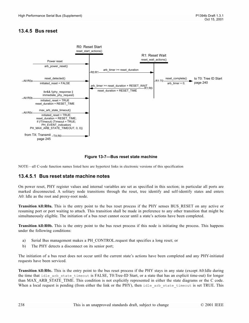
High Performance Serial Bus (Supplement) P1394b Draft 1.3.1Oct 15, 2001
13.4.5 Bus reset
NOTEall C-code function names listed here are hypertext links in electronic versions of this specification
13.4.5.1 Bus reset state machine notes
On power reset, PHY register values and internal variables are set as specified in this section; in particular all ports aremarked disconnected. A solitary node transitions through the reset, tree identify and self-identify states and entersA0: Idle as the root and proxy-root node.
Transition All:R0a. This is the entry point to the bus reset process if the PHY senses BUS_RESET on any active orresuming port or port waiting to attach. This transition shall be made in preference to any other transition that might besimultaneously eligible. The initiation of a bus reset cannot occur until a states actions have been completed.
Transition All:R0b. This is the entry point to the bus reset process if this node is initiating the process. This happensunder the following conditions:
a) Serial Bus management makes a PH_CONTROL.request that specifies a long reset; orb) The PHY detects a disconnect on its senior port;
The initiation of a bus reset does not occur until the current states actions have been completed and any PHY-initiatedrequests have been serviced.
Transition All:R0c. This is the entry point to the bus reset process if the PHY stays in any state (except A0:Idle duringthe time that idle_arb_state_timeout is FALSE, T0:Tree-ID Start, or a state that has an explicit time-out) for longerthan MAX_ARB_STATE_TIME. This condition is not explicitly represented in either the state diagrams or the C code.When a local request is pending (from either the link or the PHY), then idle_arb_state_timeout is set TRUE. This
Figure 13-7Bus reset state machine
R1: Reset Waitreset_wait_actions()
arb_timer >= reset_duration
R0: Reset Startreset_start_actions()
initiated_reset = TRUEreset_duration = RESET_TIME
reset_detected()
initiated_reset = FALSE
ibr&& !(phy_response || immediate_phy_request)
arb_timer >= reset_duration + RESET_WAIT
All:R0a
All:R0b
R0:R1
R1:R0
reset_complete()R1:T0
reset_duration = RESET_TIME
arb_timer = 0;
Power reset
arb_power_reset()
TX:R0
to T0: Tree ID Startpage 240
from TX: Transmitpage 245
initiated_reset = TRUE;reset_duration = RESET_TIME;if (!Timeout) Timeout = TRUE;
PH_EVENT_indication(PH_MAX_ARB_STATE_TIMEOUT, 0, 0)
max_arb_state_timeout()All:R0c
238 This is an unapproved standards draft, subject to change © 2001 IEEE
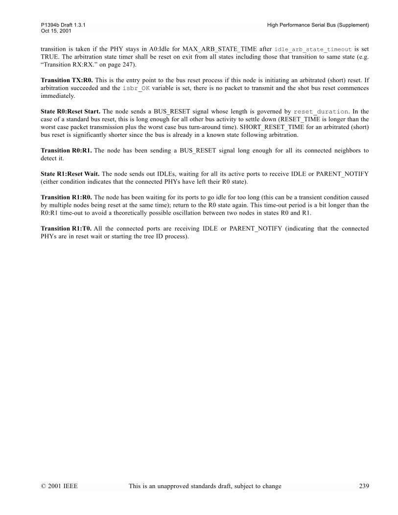
P1394b Draft 1.3.1 High Performance Serial Bus (Supplement)Oct 15, 2001
transition is taken if the PHY stays in A0:Idle for MAX_ARB_STATE_TIME after idle_arb_state_timeout is setTRUE. The arbitration state timer shall be reset on exit from all states including those that transition to same state (e.g.Transition RX:RX. on page 247).
Transition TX:R0. This is the entry point to the bus reset process if this node is initiating an arbitrated (short) reset. Ifarbitration succeeded and the isbr_OK variable is set, there is no packet to transmit and the shot bus reset commencesimmediately.
State R0:Reset Start. The node sends a BUS_RESET signal whose length is governed by reset_duration. In thecase of a standard bus reset, this is long enough for all other bus activity to settle down (RESET_TIME is longer than theworst case packet transmission plus the worst case bus turn-around time). SHORT_RESET_TIME for an arbitrated (short)bus reset is significantly shorter since the bus is already in a known state following arbitration.
Transition R0:R1. The node has been sending a BUS_RESET signal long enough for all its connected neighbors todetect it.
State R1:Reset Wait. The node sends out IDLEs, waiting for all its active ports to receive IDLE or PARENT_NOTIFY(either condition indicates that the connected PHYs have left their R0 state).
Transition R1:R0. The node has been waiting for its ports to go idle for too long (this can be a transient condition causedby multiple nodes being reset at the same time); return to the R0 state again. This time-out period is a bit longer than theR0:R1 time-out to avoid a theoretically possible oscillation between two nodes in states R0 and R1.
Transition R1:T0. All the connected ports are receiving IDLE or PARENT_NOTIFY (indicating that the connectedPHYs are in reset wait or starting the tree ID process).
© 2001 IEEE This is an unapproved standards draft, subject to change 239
High Performance Serial Bus (Supplement) P1394b Draft 1.3.1Oct 15, 2001
13.4.6 Tree ID
NOTEall C-code function names listed here are hypertext links in electronic versions of this specification
13.4.6.1 Tree ID state machine notes
State T0: Tree-ID Start. In this state, a node waits up to a CONFIG_TIMEOUT period to receive thePARENT_NOTIFY signal from at least all but one of its active ports. When PARENT_NOTIFY is observed, that port ismarked as a child port.
Transition T0:T0. If there's a loop of active ports on the bus, then a configuration timeout occurs, setting the T0_timeoutflag. All active ports operating in Beta mode are forced back into the untested state. This may indeed directly result inthe bus initialization completing, or may allow the loop free build process to set appropriate Beta mode ports into the loopdisabled state, allowing a fresh bus reset to complete.
Transition T0:T1. If a node detects the PARENT_NOTIFY signal on all of its ports, or all but one of its ports, it knowsit is either the root or a branch; it can start the handshake process with its children. Leaf nodes (those with only one con-nected port) or root nodes (PARENT_NOTIFY on all ports) take this transition immediately. If the force_root flag is set,the test for the all but one port condition is delayed long enough that all other nodes on the bus will have transitionedat least to state T1 so all the ports should then be receiving the PARENT_NOTIFY signal (this extra delay is theFORCE_ROOT_TIMEOUT value).
State T1: Child Handshake. All ports that have been labeled as child ports transmit the CHILD_NOTIFY signal. Thisallows the nodes attached to this nodes child port(s) to transition from T2 to S0. Leaf nodes have no children, so they exitthis state immediately via transition T1:T2. If all ports are labeled as child ports, then the node knows it is the root.
Figure 13-8Tree-ID state machine
((!force_root || arb_timer >= FORCE_ROOT_TIMEOUT) && children == NPORT - 1) || children == NPORTT0:T1
T1: Child Handshakechild_handshake_actions()
T0: Tree ID Starttree_ID_start_actions()
T2: Parent HandshakeT3: Root Contention
root_contend_actions()
R1:T0
child_handshake_complete()T1:T2
!root && portRarb[parent_port] == ROOT_CONTENTION
T2:T3
T3:T1child[parent_port] = TRUE
arb_timer > contend_time &&portRarb[parent_port] == IDLE
T3:T2portTarb(parent_port, PARENT_NOTIFY)
root || portRarb[parent_port] == PARENT_HANDSHAKET2:S0
T0_timeout = TRUE;if (loop == 0) loop = 1; PH_EVENT_indication(PH_CONFIG_TIMEOUT, 0, 0)
T0:T0!T0_timeout && (arb_timer == config_timeout)
to S0: Self-ID Startpage 242
from R1: Reset Waitpage 238
arb_timer > contend_time &&portRarb[parent_port] == PARENT_NOTIFY
240 This is an unapproved standards draft, subject to change © 2001 IEEE
P1394b Draft 1.3.1 High Performance Serial Bus (Supplement)Oct 15, 2001
Transition T1:T2. When all of a nodes children stop sending PARENT_NOTIFY, it then waits until it sees theCHILD_HANDSHAKE signal on all of its child ports. It then knows they have all transitioned to the self-ID start state,so the node can now handshake with its own parent.
State T2: Parent Handshake. At this point, a node is waiting to receive PARENT_HANDSHAKE signal (for DS con-nections, this is the result of the node sending PARENT_NOTIFY and its parent sending CHILD_NOTIFY). This step isbypassed if the node is root (receiving PARENT_NOTIFY on all connected ports). Another way this state can be exited isif it receives the ROOT_CONTENTION signal from its parent.
Transition T2:S0. When the node receives the PARENT_HANDSHAKE signal, it starts the self-ID process by sendingthe IDLE signal (see State S0: Self-ID Start, below). It also takes this transition if it is root, since it doesnt have a parent.
Transition T2:T3. If a node receives a PARENT_NOTIFY signal on the same port that it is sending aPARENT_NOTIFY signal, the merged signal is interpreted as ROOT_CONTENTION. This can only happen for a singlepair of nodes if each bids to make the other node its parent.
State T3: Root Contention. At this point, both nodes back off by sending an IDLE signal, starting a timer, and picking arandom bit. If the random bit is one, the node waits longer than if it is a zero. When the timer has expired, the node sam-ples the contention port once again.
Transition T3:T2. If a node receives an IDLE signal on its proposed parent port at the end of the delay, it once againsends the PARENT_NOTIFY signal. If the other node is taking longer it takes the T3:T1 transition and allows this nodeto exit state T2 via the self-ID start path. Otherwise the two nodes again see the ROOT_CONTENTION signal and repeatthe root contention process with a new set of random bits.
Transition T3:T1. If a node receives a PARENT_NOTIFY signal on the proposed parent port at the end of the delay itmeans the other node has already transitioned to state T2, so this node returns to state T1 and becomes the root.
© 2001 IEEE This is an unapproved standards draft, subject to change 241
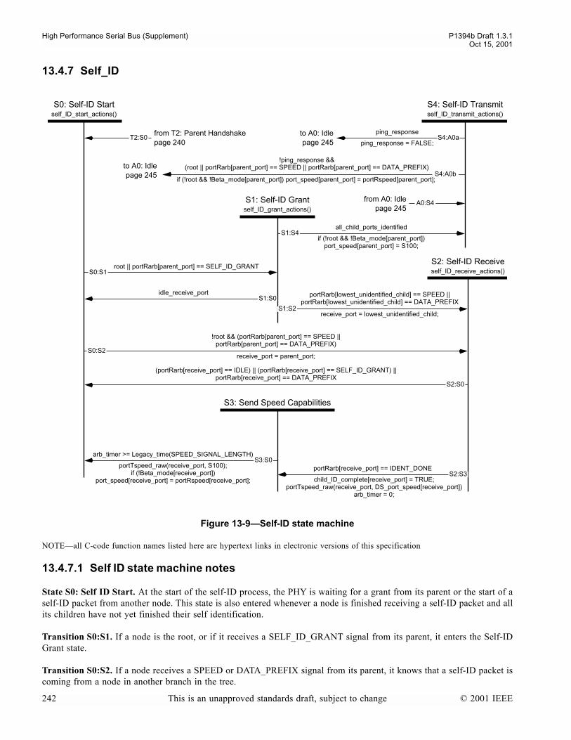
High Performance Serial Bus (Supplement) P1394b Draft 1.3.1Oct 15, 2001
13.4.7 Self_ID
NOTEall C-code function names listed here are hypertext links in electronic versions of this specification
13.4.7.1 Self ID state machine notes
State S0: Self ID Start. At the start of the self-ID process, the PHY is waiting for a grant from its parent or the start of aself-ID packet from another node. This state is also entered whenever a node is finished receiving a self-ID packet and allits children have not yet finished their self identification.
Transition S0:S1. If a node is the root, or if it receives a SELF_ID_GRANT signal from its parent, it enters the Self-IDGrant state.
Transition S0:S2. If a node receives a SPEED or DATA_PREFIX signal from its parent, it knows that a self-ID packet iscoming from a node in another branch in the tree.
Figure 13-9Self-ID state machine
root || portRarb[parent_port] == SELF_ID_GRANT
S0: Self-ID Startself_ID_start_actions()
S3: Send Speed Capabilities
S2: Self-ID Receiveself_ID_receive_actions()
all_child_ports_identified
S1: Self-ID Grantself_ID_grant_actions()
if (!root && !Beta_mode[parent_port]) port_speed[parent_port] = S100;
receive_port = lowest_unidentified_child;
portRarb[lowest_unidentified_child] == SPEED ||portRarb[lowest_unidentified_child] == DATA_PREFIX
S0:S2
S1:S2
S0:S1
S1:S4
T2:S0
!root && (portRarb[parent_port] == SPEED ||portRarb[parent_port] == DATA_PREFIX)
receive_port = parent_port;
ping_response
ping_response = FALSE;S4:A0a
S4: Self-ID Transmitself_ID_transmit_actions()
!ping_response && (root || portRarb[parent_port] == SPEED || portRarb[parent_port] == DATA_PREFIX)
if (!root && !Beta_mode[parent_port]) port_speed[parent_port] = portRspeed[parent_port]; S4:A0b
S2:S0
(portRarb[receive_port] == IDLE) || (portRarb[receive_port] == SELF_ID_GRANT) ||portRarb[receive_port] == DATA_PREFIX
portTspeed_raw(receive_port, S100);if (!Beta_mode[receive_port])
port_speed[receive_port] = portRspeed[receive_port];
arb_timer >= Legacy_time(SPEED_SIGNAL_LENGTH)S3:S0
child_ID_complete[receive_port] = TRUE;portTspeed_raw(receive_port, DS_port_speed[receive_port])
arb_timer = 0;
portRarb[receive_port] == IDENT_DONES2:S3
A0:S4
idle_receive_portS1:S0
from T2: Parent Handshakepage 240
to A0: Idlepage 245
to A0: Idlepage 245
from A0: Idlepage 245
242 This is an unapproved standards draft, subject to change © 2001 IEEE

P1394b Draft 1.3.1 High Performance Serial Bus (Supplement)Oct 15, 2001
State S1: Self-ID Grant. This state is entered when a node is given permission to send a self-ID packet. If it has any uni-dentified children, it sends a GRANT signal to the lowest numbered of those, unless it is an uncle acting as the proxy forthat port, in which case it transmits the proxy self_ID packet. All other connected ports are sent a DATA_PREFIX signalto warn them of the start of a self-ID packet.
Transition S1:S2. When the PHY receives a SPEED or DATA_PREFIX signal from its lowest numbered unidentifiedchild, it enters the Self-ID Receive state.
Transition S1:S0. If the PHY transmitted a proxy self_ID packet, then it transitions back to S0.
Transition S1:S4. If there are no more unidentified children, it immediately transitions to the Self-ID Transmit state.
State S2: Self-ID Receive. As data symbols are received from the bus they are passed on to the link layer as PHY dataindications. Note that multiple self-ID packets may be received in this state. The parent PHY is required to also monitorthe received speed signal whenever IDENT_DONE is received from the child. Because of resynchronization delays inrepeating the packet, the parent PHY may not complete retransmission of the packet data and data end signal for up to144 ns or more (as specified by PHY_DELAY) after the start of the IDENT_DONE signal. Since the child sends its speedsignal for no more than 120 ns from the start of the IDENT_DONE signal, the parent could miss the speed signal fromthe child if it entered S3 before completing a speed signal sample. If the PHY gets an IDENT_DONE signal from thereceiving port, it flags that port as identified and, if the port is operating in DS mode, starts sending the speed capabilitiessignal. It also starts the speed signaling timer
Transition S2:S0. When the receive port goes IDLE, gets a SELF_ID_GRANT or observes DATA_PREFIX for a uncon-catenated packet it enters the Self-ID Start state to continue the self-ID process for the next child. The last case guardsagainst a possible failure to observe IDLE.
Transition S2:S3. The port has received an IDENT_DONE from the child.
State S3: Send Speed Capabilities. If a node is capable of sending data at a higher rate that S100 and the receiving portis operating in DS mode, it transmits on the receiving child port its speed capability signals for a fixed durationSPEED_SIGNAL_LENGTH. The parent PHY is required to also monitor the received speed-signal wheneverIDENT_DONE is received from the child.
Transition S3:S0. When the speed signaling timer expires, and the receive port is operating in DS mode, any signals sentby the child have been latched, so it is safe to continue with the next child port. This is also the point at whichnegotiated_speed in the port register map is set for DS mode operation
State S4: Self-ID Transmit. This state may be entered either as part of the self-identify process or as the result of thereceipt of a PHY ping packet. In the latter case, any pending Legacy link requests are cancelled and the set of self-IDpackets are transmitted. When state S4 is entered as part of the self-identify process, the actions are more complex, asdescribed below.
At this point, all child ports have been flagged as identified, so the PHY can now send its own self-ID packet. When anon-root node is finished, it sends a IDENT_DONE signal while simultaneously transmitting a speed capability signal toits parent and IDLE to its children. The speed capability signal is transmitted for a fixed time duration ofSPEED_SIGNAL_LENGTH. Simultaneously it monitors the bus for a speed capability transmission from the parent. Thehighest indicated speed is recorded as the speed capability of the parent. The root node just sends IDLE to its children.Note that the children will then enter the Idle state described in the next clause, but children on DS ports will never startarbitration since an adequate arbitration gap will never open up until the Self-ID process is completed for all nodes.
While transmitting the IDENT_DONE signal in the S4 state, the child monitors the received speed-signal from the parent.The child PHY then transitions to the A0:Idle state when it receives an DATA_PREFIX signal from its parent. The parentPHY will be in the S2:Self-ID-Receive state to receive the self-ID packet(s) from the child. When the parent PHYreceives an IDENT_DONE signal from the child PHY, the parent transitions to the S3:Send-Speed-Capabilities state. In
© 2001 IEEE This is an unapproved standards draft, subject to change 243

High Performance Serial Bus (Supplement) P1394b Draft 1.3.1Oct 15, 2001
the S3 state, the parent transmits a speed-signal for 100-120 ns to indicate its own speed capability, and monitors thereceived speed-signal from the child. The highest indicated speed is recorded as the speed capability of the child. Aftertransmitting its own speed-signal the parent PHY transitions to the S0:Self-ID-Start state.
Transition S4:A0b. The PHY then enters the Idle state described in the next clause when the self-ID packet has beentransmitted, this is not a ping response, and if either of the following conditions are met:
a) The node is the root. When the root enters the Idle state, all nodes are now sending IDLE signals and the gaptimers will eventually get large enough to allow normal arbitration to start.
b) The node starts to receive a new self-ID packet (SPEED or DATA_PREFIX). This will be the self-ID packet forthe parent node or another child of the parent. This event shall cause the PHY to transition immediately out ofA0:Idle into RX:Receive
If the parent port will be operating in DS mode, this is when the negotiated_speed field in the port register map for theparent port is set.
244 This is an unapproved standards draft, subject to change © 2001 IEEE

P1394b Draft 1.3.1 High Performance Serial Bus (Supplement)Oct 15, 2001
13.4.8 Arbitration
Figure 13-10Border arbitration state machine
!immediate_request && !proxy_root && (Legacy_junior_request || arb_OK)
concatenated_packet
// Reinvokes receive_actions()
!concatenated_packet && !(fly_by_OK || grant_self) && requesting_port == NPORT
LEGACY_GRANT() && own_request
// Arbitration WON
A0: Idleidle_actions()
TX: Transmittransmit_actions()
RX: Receivereceive_actions()
A2: Grantgrant_actions()
LEGACY_GRANT() && !own_request &&(Legacy_junior_request || converted_request)
!active[requesting_port] || portRarb[requesting_port] == REQUEST_CANCEL
send_null_packet = TRUE;
A1: Legacy RequestLegacy_request_actions()
(proxy_root && (Legacy_junior_request ) && !arb_OK) || Beta_port_request
// Arbitration WON
end_of_packet && !grant_self && requesting_port == NPORT
RX:A0
data_coming_on(requesting_port);
RX:RX
receive_port = senior_port// Arbitration LOST or deferred
data_coming_on(senior_port);
end_of_packet && grant_self
// Reinvokes transmit_actions()
A0:RX
TX:A0
A0:TX
A1:TX
A1:RX
A0:A1 A1:A2
A2:TX
A0:A2
A2:RX
TX:R0
data_coming()
// Arbitration LOST or deferred
!concatenated_packet && (fly_by_OK || grant_self) && requesting_port == NPORT
// Arbitration WONRX:TX
ping_responseA0:S4
TX:TX
isbr_OK
initiated_reset = TRUEreset_duration = SHORT_RESET_TIME
receive_port = requesting_port
S4:A0b
immediate_request ||(proxy_root && arb_OK) || grant_self
S4:A0a
PH: PHY Responsephy_response_actions()
// Transmit a PHY packetA0:PH
phy_response
PH:A0
to S4: Self-ID Transmitpage 242
from S4: Self-ID Transmitpage 242
to R0: Reset Startpage 238
gap_token(senior_port);A1:A1
to TX:Transmit
A2:TX
RX:A2requesting_port != NPORT
TX:A2
end_of_packet && !grant_self && requesting_port != NPORT
to A2: Grant
TX:A2
© 2001 IEEE This is an unapproved standards draft, subject to change 245

High Performance Serial Bus (Supplement) P1394b Draft 1.3.1Oct 15, 2001
NOTEall C-code function names listed here are hypertext links in electronic versions of this specification
13.4.8.1 Arbitration state machine notes
State A0: Idle. All inactive nodes stay in the idle state until an internal or external event. All DS ports transmit the IDLEarbitration signal or DATA_PREFIX (if the ds_stuck flag is set) while Beta ports follow the Beta mode request repeat-ing rules (see clause 13.4.2.1).
Transition A0:A1. If the PHY is not the proxy_root and
a) receives a LEGACY_REQUEST signal from one of its junior ports, b) or it has a non-immediate queued request from its own Legacy link and meets the legacy timing requirements
(arb_OK()), c) or it is a senior border and it has a non-immediate queued request from its own link or a BOSS arbitration request
from one of its junior ports and meets the legacy timing requirements (arb_OK()),
then it passes the request on to its senior. The arb_OK() function qualifies asynchronous requests according to the timeelapsed since A0: Idle was last entered. In particular, notice that the test for a subaction gap is performed for a singlevalue (equality), not a greater than comparison. If arbitration were to be initiated at other times between the detection ofa subaction gap and an arbitration reset gap, some nodes could mistakenly observe an arbitration reset gap.
NOTEThe intent is any legacy launched requests are forwarded immediately up the tree, regardless of whether the senior port is DSor Beta (a). Also, any request from a Legacy link gets launched on the bus and forwarded up the tree as a LEGACY_REQUEST aftertimings have been met regardless of the senior port's type (b). Finally, any Beta cloud which doesn't contain the proxy_root has toconvert all requests to LEGACY_REQUESTs and forward then, via DS, to the proxy_root's cloud. This is the responsibility of thesenior border in each Beta cloud: hence (c).
Transition A0:A2. If, on the other hand, the PHY receives a LEGACY_REQUEST from one of its junior ports, has noqueued requests from its own Legacy link and is the proxy_root, it starts the bus grant process. If there is noLEGACY_REQUEST, it shall also start the bus grant process if a request is received on a Beta port (but not its attachedlink).
Transition A0:PH. If an extended PHY packet (other than the ping packet) has been received, a response is required.
Transition A0:TX. If the PHY has a queued request from its own Legacy link and it is the proxy_root, or the PHY has aqueued request from its own Beta link and it either receives a grant token or it is BOSS and the last subaction is complete,or if the PHY has a queued immediate request (generated during packet reception if the link layer needs to send anacknowledge); then the PHY notifies the link layer that it is ready to transmit and enters the Transmit state.
Transition A0:S4. In response to the receipt of a PHY ping packet, the variable ping_response is set TRUE and a tran-sition is made to the Self-ID Transmit State to send the self-ID packet(s).
Transition A0:RX. if a PHY starts receiving a packet, it immediately enters the Receive state.
State A1: Legacy Request. A PHY wishes to send a Legacy request and is required to forward that request towards theproxy_root. The PHY sends a LEGACY_REQUEST signal to its senior port and a DATA_NULL to all its non-requestingjunior ports (data prefix for DS ports).
Transition A1:A1. If the PHY receives an asynchronous start or arbitration reset token on a Beta port while waiting to begranted for a LEGACY_REQUEST, then it sets a flag to cause the token to be repeated.
Transition A1:A2. If the PHY receives a GRANT signal from its senior port, and it does not have a pending request fromits attached link, and either a legacy request or (for a senior border) a converted beta request is active on a junior port, thePHY grants the bus to that port.
246 This is an unapproved standards draft, subject to change © 2001 IEEE
P1394b Draft 1.3.1 High Performance Serial Bus (Supplement)Oct 15, 2001
Transition A1:RX. If the PHY see data_coming_on its senior port, then it knows that it has lost the arbitration processand prepares to receive a packet. If the link layer was making the request, it is notified.
Transition A1:TX. If the PHY receives a GRANT signal from its senior port and the link layer has an outstandingrequest (asynchronous or isochronous), the PHY enters the Transmit state.
State A2: Grant. During the grant process, the requesting junior port is sent a GRANT signal and the other junior portsare sent DATA_NULL so that they prepare to receive a packet.
Transition A2:RX. If the PHY sees data_coming_on the requesting junior port, the grant handshake is complete and thenode goes into the Receive state.
Transition A2:TX. If the requesting junior port withdraws its request (the granting PHY sees a REQUEST_CANCELsignal) or is no longer active, the PHY goes directly to the Transmit state to send a null packet.
State PH: PHY Response. When the node has received an extended PHY packet (other than the ping packet) thatrequires a response, this state takes the appropriate actions, builds a remote reply or remote confirmation packet andtransmits the packet from all active ports.
Transition PH:A0. After transmitting the PHY response packet, return unconditionally to idle.
State RX: Receive. When the node starts the receive process, it notifies the link layer that the bus is busy and starts thepacket receive process described below. Outstanding fair and priority requests from a Legacy link are cancelledimme-diately if arbitration enhancements are globally disabled, otherwise by the receipt of any packet other than an acknowl-edgementand the link will have to reissue them later. Requests by Beta links are not cancelled. Note that the packetreceived could be a PHY packet (self-ID, link-on or PHY configuration), acknowledge, or normal data packet. PHY con-figuration and link-on packets are interpreted by the PHY, as well as being passed on to the link layer.
Transition RX:A0. If transmitting node stops sending a packet and no additional packet is concatenated to it (thereceived signal is DATA_END or IDLE) and the PHY cannot concatenate a queued packet of its own (fly-by arbitrationis disabled or there is no queued packet), the bus is released and the PHY returns to the idle state.
Transition RX:A2. If a transmitting node finishes sending a packet and there are active requests from its junior ports andthere is not a concatenated packet, the PHY goes to the grant state.
Transition RX:RX. If a packet ends but another packet is concatenated to it, the receive process is restarted. The arbitra-tion state timer is reset.
Transition RX:TX. If fly-by arbitration is enabled and an acknowledge or isochronous packet ends (and another packetis not concatenated to it), or at the explicit end of a subaction, a queued request may be granted.
State TX: Transmit. Unless an arbitrated (short) bus reset has been requested, the transmission of a packet starts by thenode sending a SPEED and DATA_PREFIX signals (as appropriate), and then sending PHY clock indications to the linklayer. For each clock indication, the link sends a PHY data request. The clock indication data request sequence repeatsuntil the link sends a PH_REQ_DATA_PREFIX, PH_REQ_DATA_END or PH_REQ_SUBACTION_END. Concatenatedpackets are handled within this state whenever the link sends a PH_REQ_DATA_PREFIX. The arbitration enable flag iscleared if this was a fair Legacy request.
Transition TX:A0. If node has finished sending a packet and the link layer is not requesting concatenation of anotherpacket and the node cannot grant any pending Beta requests (not the end of a subaction), the PHY returns to the Idle state.
Transition TX:A2. If the link layer has finished sending a packet and is not requesting concatenation of another packetand there is no queued request from its own Beta link and if the PHY can grant a request from one of its Beta ports (theprevious packet was the end of a subaction), the PHY transitions to the Grant state to send a GRANT signal to a request-ing Beta port.
© 2001 IEEE This is an unapproved standards draft, subject to change 247

High Performance Serial Bus (Supplement) P1394b Draft 1.3.1Oct 15, 2001
Transition TX:R0. If arbitration succeeded and the isbr_OK variable is set, there is no packet to transmit. The PHY tran-sitions to the Reset start state to commence a short bus reset.
Transition TX:TX. If node has finished sending a packet and the link layer is requesting concatenation of another packetor if the node can grant a pending Beta request from its own link (the PHY is BOSS and the previous packet was the endof a subaction), the PHY returns to the Transmit state to send the new packet.
248 This is an unapproved standards draft, subject to change © 2001 IEEE

P1394b Draft 1.3.1 High Performance Serial Bus (Supplement)Oct 15, 2001
14. B PHY link Interface (parallel)
This section specifies the signalling, protocol and electrical characteristics of the interface between a discrete PHY and alink. The interface is described independently of other operational characteristics of either PHY or link. The PHY-linkinterface specifies a point-to-point communications mechanism between a single B link and PHY for the purpose of trans-fer of 1394 packet and status information between these two devices.
Implementation of the PHY-link interface at speeds up to S800 may be achieved using an 8-bit parallel interface which isclosely modeled on the PHY-link interface defined in IEEE Std 1394a-2000. The PHY-link interface provides mechanismsto support communication between discrete PHY and link at speeds of S100, S200, S400 and S800. For all of thesespeeds, the width of the data path is 8-bits. Transfer speeds lower than the maximum are accommodated by data paddingand repetition.
This specification does not preclude implementation of PHYs that are capable of supporting links compliant with thisstandard and with the 1394a-2000 standard. When attached to a link that is compliant with the 1394a-2000 standard, thePHY shall follow all the link specifications of that standard. When attached to a link compliant with this standard, thePHY shall follow the link specification contained in this clause.
14.1 B PHY-link Interface Characteristics
The following are the characteristics of the B PHY-link interface
a) provides for bi-directional 1394 packet data transfer at S100, S200, S400 and S800 speeds;b) provides a mechanism for status information transfer from the PHY to the link;c) provides a mechanism for the link to access a register space within the PHY;d) provides a means for the link to request services from the PHY;e) provides a means for the PHY to interrupt the link during an operation; andf) supports an optional isolation interface to allow separate PHY and link power supply domains.
© 2001 IEEE This is an unapproved standards draft, subject to change 249

High Performance Serial Bus (Supplement) P1394b Draft 1.3.1Oct 15, 2001
14.2 PHY-link Interface Signals
14.2.1 Interface Signal Descriptions
The signals of the B PHY-link interface are divided into mandatory and optional signals for the PHY and link.
14.2.1.1 PHY Signals
The mandatory signals for a PHY are: D[0:7], PInt, LReq, Ctl[0:1], PClk, LClk, LinkOn and LPS. The Direct andBeta_Mode signals are optional for a PHY.
The propagation delay for the signals from the PHY to the link shall be less than 1.5 ns. including any delays caused byisolation barriers.
14.2.1.2 Link Signals
The mandatory signals for a link are: D[0:7], PInt, LReq, Ctl[0:1], PClk and LClk. The LinkOn, LPS and Direct signalsare optional for a link.
The propagation delay for the signals from the link to the PHY shall be less than 1.5 ns including any delays caused byisolation barriers.
NOTEthis diagram indicates the logical signalling required between the PHY and link and does not imply a DC connection between the two devices.
Figure 14-1PHY-link Interface Logical Signalling
B PHY B link
D[0:7] D[0:7]
LReqPInt
Ctl[0:1] Ctl[0:1]
LClkPClk
Direct
LinkOnLPS
8
2
PClkLClk
LinkOnLPS
PIntLReq
Beta_Mode_link
Direct
250 This is an unapproved standards draft, subject to change © 2001 IEEE
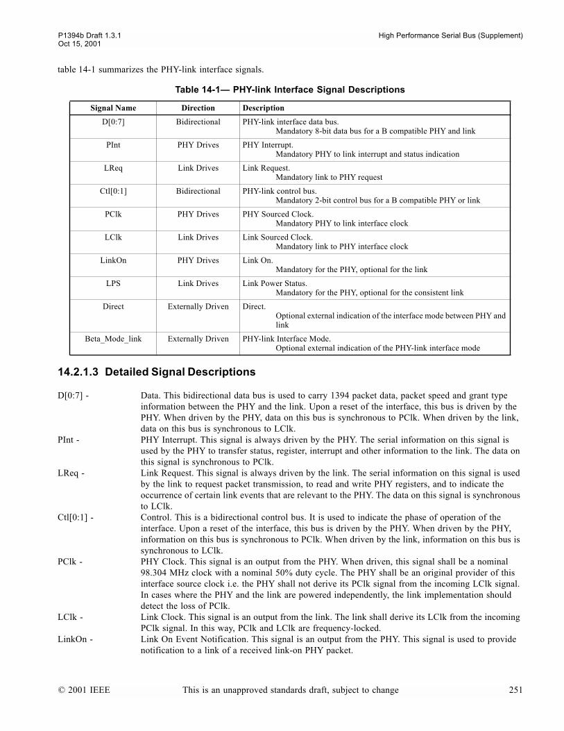
P1394b Draft 1.3.1 High Performance Serial Bus (Supplement)Oct 15, 2001
table 14-1 summarizes the PHY-link interface signals.
14.2.1.3 Detailed Signal Descriptions
D[0:7] - Data. This bidirectional data bus is used to carry 1394 packet data, packet speed and grant type information between the PHY and the link. Upon a reset of the interface, this bus is driven by the PHY. When driven by the PHY, data on this bus is synchronous to PClk. When driven by the link, data on this bus is synchronous to LClk.
PInt - PHY Interrupt. This signal is always driven by the PHY. The serial information on this signal is used by the PHY to transfer status, register, interrupt and other information to the link. The data on this signal is synchronous to PClk.
LReq - Link Request. This signal is always driven by the link. The serial information on this signal is used by the link to request packet transmission, to read and write PHY registers, and to indicate the occurrence of certain link events that are relevant to the PHY. The data on this signal is synchronous to LClk.
Ctl[0:1] - Control. This is a bidirectional control bus. It is used to indicate the phase of operation of the interface. Upon a reset of the interface, this bus is driven by the PHY. When driven by the PHY, information on this bus is synchronous to PClk. When driven by the link, information on this bus is synchronous to LClk.
PClk - PHY Clock. This signal is an output from the PHY. When driven, this signal shall be a nominal 98.304 MHz clock with a nominal 50% duty cycle. The PHY shall be an original provider of this interface source clock i.e. the PHY shall not derive its PClk signal from the incoming LClk signal. In cases where the PHY and the link are powered independently, the link implementation should detect the loss of PClk.
LClk - Link Clock. This signal is an output from the link. The link shall derive its LClk from the incoming PClk signal. In this way, PClk and LClk are frequency-locked.
LinkOn - Link On Event Notification. This signal is an output from the PHY. This signal is used to provide notification to a link of a received link-on PHY packet.
Table 14-1 PHY-link Interface Signal Descriptions
Signal Name Direction Description
D[0:7] Bidirectional PHY-link interface data bus.Mandatory 8-bit data bus for a B compatible PHY and link
PInt PHY Drives PHY Interrupt.Mandatory PHY to link interrupt and status indication
LReq Link Drives Link Request.Mandatory link to PHY request
Ctl[0:1] Bidirectional PHY-link control bus.Mandatory 2-bit control bus for a B compatible PHY or link
PClk PHY Drives PHY Sourced Clock.Mandatory PHY to link interface clock
LClk Link Drives Link Sourced Clock.Mandatory link to PHY interface clock
LinkOn PHY Drives Link On.Mandatory for the PHY, optional for the link
LPS Link Drives Link Power Status. Mandatory for the PHY, optional for the consistent link
Direct Externally Driven Direct.Optional external indication of the interface mode between PHY and link
Beta_Mode_link Externally Driven PHY-link Interface Mode.Optional external indication of the PHY-link interface mode
© 2001 IEEE This is an unapproved standards draft, subject to change 251
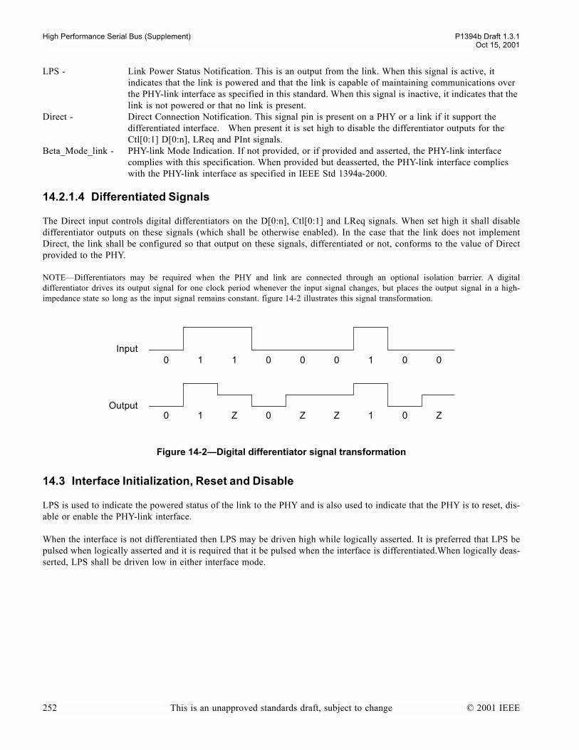
High Performance Serial Bus (Supplement) P1394b Draft 1.3.1Oct 15, 2001
LPS - Link Power Status Notification. This is an output from the link. When this signal is active, it indicates that the link is powered and that the link is capable of maintaining communications over the PHY-link interface as specified in this standard. When this signal is inactive, it indicates that the link is not powered or that no link is present.
Direct - Direct Connection Notification. This signal pin is present on a PHY or a link if it support the differentiated interface. When present it is set high to disable the differentiator outputs for the Ctl[0:1] D[0:n], LReq and PInt signals.
Beta_Mode_link - PHY-link Mode Indication. If not provided, or if provided and asserted, the PHY-link interface complies with this specification. When provided but deasserted, the PHY-link interface complies with the PHY-link interface as specified in IEEE Std 1394a-2000.
14.2.1.4 Differentiated Signals
The Direct input controls digital differentiators on the D[0:n], Ctl[0:1] and LReq signals. When set high it shall disabledifferentiator outputs on these signals (which shall be otherwise enabled). In the case that the link does not implementDirect, the link shall be configured so that output on these signals, differentiated or not, conforms to the value of Directprovided to the PHY.
NOTEDifferentiators may be required when the PHY and link are connected through an optional isolation barrier. A digitaldifferentiator drives its output signal for one clock period whenever the input signal changes, but places the output signal in a high-impedance state so long as the input signal remains constant. figure 14-2 illustrates this signal transformation.
14.3 Interface Initialization, Reset and Disable
LPS is used to indicate the powered status of the link to the PHY and is also used to indicate that the PHY is to reset, dis-able or enable the PHY-link interface.
When the interface is not differentiated then LPS may be driven high while logically asserted. It is preferred that LPS bepulsed when logically asserted and it is required that it be pulsed when the interface is differentiated.When logically deas-serted, LPS shall be driven low in either interface mode.
Figure 14-2Digital differentiator signal transformation
0 1 1 0 0 0 1 0 0
0 1 Z 0 Z Z 1 0 Z
Input
Output
252 This is an unapproved standards draft, subject to change © 2001 IEEE
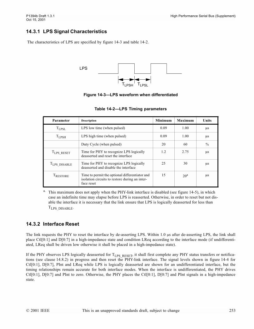
P1394b Draft 1.3.1 High Performance Serial Bus (Supplement)Oct 15, 2001
14.3.1 LPS Signal Characteristics
The characteristics of LPS are specified by figure 14-3 and table 14-2.
14.3.2 Interface Reset
The link requests the PHY to reset the interface by de-asserting LPS. Within 1.0 µs after de-asserting LPS, the link shallplace Ctl[0:1] and D[0:7] in a high-impedance state and condition LReq according to the interface mode (if undifferenti-ated, LReq shall be driven low otherwise it shall be placed in a high-impedance state).
If the PHY observes LPS logically deasserted for TLPS_RESET, it shall first complete any PHY status transfers or notifica-tions (see clause 14.8.2) in progress and then reset the PHY-link interface. The signal levels shown in figure 14-4 forCtl[0:1], D[0:7], PInt and LReq while LPS is logically deasserted are shown for an undifferentiated interface, but thetiming relationships remain accurate for both interface modes. When the interface is undifferentiated, the PHY drivesCtl[0:1], D[0:7] and PInt to zero. Otherwise, the PHY places the Ctl[0:1], D[0:7] and PInt signals in a high-impedancestate.
Figure 14-3LPS waveform when differentiated
Table 14-2LPS Timing parameters
Parameter Description Minimum Maximum Units
TLPSL LPS low time (when pulsed) 0.09 1.00 µs
TLPSH LPS high time (when pulsed) 0.09 1.00 µs
Duty Cycle (when pulsed) 20 60 %
TLPS_RESET Time for PHY to recognize LPS logically deasserted and reset the interface
1.2 2.75 µs
TLPS_DISABLE Time for PHY to recognize LPS logically deasserted and disable the interface
25 30 µs
TRESTORE Time to permit the optional differentiator and isolation circuits to restore during an inter-face reset
15 20a
a. This maximum does not apply when the PHY-link interface is disabled (see figure 14-5), in which case an indefinite time may elapse before LPS is reasserted. Otherwise, in order to reset but not dis-able the interface it is necessary that the link ensure that LPS is logically deasserted for less than TLPS_DISABLE.
µs
LPS
TLPSH TLPSL
© 2001 IEEE This is an unapproved standards draft, subject to change 253
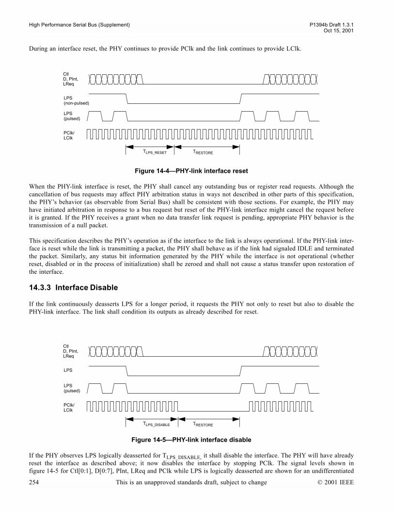
High Performance Serial Bus (Supplement) P1394b Draft 1.3.1Oct 15, 2001
During an interface reset, the PHY continues to provide PClk and the link continues to provide LClk.
When the PHY-link interface is reset, the PHY shall cancel any outstanding bus or register read requests. Although thecancellation of bus requests may affect PHY arbitration status in ways not described in other parts of this specification,the PHYs behavior (as observable from Serial Bus) shall be consistent with those sections. For example, the PHY mayhave initiated arbitration in response to a bus request but reset of the PHY-link interface might cancel the request beforeit is granted. If the PHY receives a grant when no data transfer link request is pending, appropriate PHY behavior is thetransmission of a null packet.
This specification describes the PHYs operation as if the interface to the link is always operational. If the PHY-link inter-face is reset while the link is transmitting a packet, the PHY shall behave as if the link had signaled IDLE and terminatedthe packet. Similarly, any status bit information generated by the PHY while the interface is not operational (whetherreset, disabled or in the process of initialization) shall be zeroed and shall not cause a status transfer upon restoration ofthe interface.
14.3.3 Interface Disable
If the link continuously deasserts LPS for a longer period, it requests the PHY not only to reset but also to disable thePHY-link interface. The link shall condition its outputs as already described for reset.
If the PHY observes LPS logically deasserted for TLPS_DISABLE, it shall disable the interface. The PHY will have alreadyreset the interface as described above; it now disables the interface by stopping PClk. The signal levels shown infigure 14-5 for Ctl[0:1], D[0:7], PInt, LReq and PClk while LPS is logically deasserted are shown for an undifferentiated
Figure 14-4PHY-link interface reset
Figure 14-5PHY-link interface disable
CtlD, PInt,LReq
LPS
LPS(pulsed)
PClk/
TLPS_RESET TRESTORE
LClk
(non-pulsed)
CtlD, PInt,LReq
LPS
LPS(pulsed)
PClk/
TLPS_DISABLE TRESTORE
LClk
254 This is an unapproved standards draft, subject to change © 2001 IEEE

P1394b Draft 1.3.1 High Performance Serial Bus (Supplement)Oct 15, 2001
interface, but the timing relationships remain accurate for both modes. When the interface is undifferentiated, the PHYdisables the interface by driving PClk to zero while continuing to drive Ctl[0:1], D[0:7] and PInt to zero. Otherwise, thePHY disables the interface by placing PClk in a high-impedance state while continuing to maintain the Ctl[0:1], D[0:7]and PInt signals in a high-impedance state.
NOTEWhen the PHY-link interface is disabled and none of the PHYs ports are active or in a transitional state, the PHY may placemost of its circuitry in a low power state.
14.3.4 Restoration/Initialization
The handshake just described either resets, or resets and then disables the interface when the link deasserts LPS for a min-imum of TLPS_RESET(max) or TLPS_DISABLE(max) respectively. In either case (or after power reset), normal operations maybe restored if the link asserts LPS. After observing LPS, if PClk is not already provided by the PHY, it shall resume PClkas soon as possible, but no earlier then 10 µs since the PHYs most recent power reset. If the PHY-link interface is differ-entiated and PClk is resumed, the PHY shall commence by driving PClk low for a minimum of 2.5 ns. In either mode, thePHY shall ensure that clock duty cycle and period requirements are met from the first rising edge of PClk onwards. OncePClk is available, the PHY and link shall condition their Ctl[0:1] and D[0:7] outputs in accordance with table 14-3. Thereference point is the first rising edge of PClk after LPS is asserted.
The PHY may not be able to determine its operating mode, differentiated or undifferentiated, immediately after a powerreset. While the operating mode is indeterminate, the PHY shall place its outputs in a high-impedance state.
Upon the ninth PClk cycle the PHY shall assert RECEIVE on Ctl[0:1] while simultaneously providing DATA_ON indica-tion on D[0:7] for at least one PClk cycle. On a subsequent PClk cycle the PHY shall continue with the initialization com-pletion sequence defined in 14.3.4.1. The link may not issue any LReq until the first PHY Status Transfer is received.
The PHY shall ensure that no more than 10ms elapses from the re-assertion of LPS until the first DATA_ON indication issent by the PHY.
14.3.4.1 Initialization Completion Sequence
The following sequence of events occurs whenever the PHY-link interface comes up or is reset, or when a Nephew PHYbrings a port out of the standby state. The conditions and events of the completion sequence are:
a) there shall be no outstanding packet transfer requests to the PHY and, if the interface is being initialized or reset,there shall be no outstanding register transfer requests pending in the PHY;
Table 14-3Initialization of the PHY-link interface
DeviceInterface mode
Differentiated Undifferentiated
PHY For one and only one of the first six cycles of PClk after the reference point, drive Ctl[0:1], D[0:7] and PInt to zero and otherwise, for these cycles and the seventh, place them in a high-impedance state
Drive Ctl[0:1], D[0:7] and PInt to zero for the first seven cycles of PClk after the reference point
link For one and only one of the first six cycles of PClk after the reference point, drive Ctl[0:1], D[0:7] and LReq to zero and otherwise place them in a high-impedance state.
For one and only one of the first six cycles of PClk after the reference point, drive Ctl[0:1] and D[0:7] to zero; prior to this place them in a high-imped-ance state. Once these signals have been driven low, return them to a high-impedance state until after the reset completes.
LReq shall be driven low once the operating mode of the interface is determined and shall continue to be driven low until the first PHY Status Transfer is received.
© 2001 IEEE This is an unapproved standards draft, subject to change 255
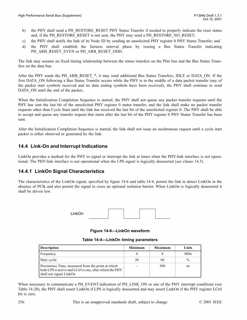
High Performance Serial Bus (Supplement) P1394b Draft 1.3.1Oct 15, 2001
b) the PHY shall send a PH_RESTORE_RESET PHY Status Transfer if needed to properly indicate the reset statusand, if the PH_RESTORE_RESET is not sent, the PHY may send a PH_RESTORE_NO_RESET;
c) the PHY shall notify the link of its Node ID by sending an unsolicited PHY register 0 PHY Status Transfer; andd) the PHY shall establish the fairness interval phase by issuing a Bus Status Transfer indicating
PH_ARB_RESET_EVEN or PH_ARB_RESET_ODD.
The link may assume no fixed timing relationship between the status transfers on the PInt line and the Bus Status Trans-fers on the data bus.
After the PHY sends the PH_ARB_RESET_*, it may send additional Bus Status Transfers, IDLE or DATA_ON. If thefirst DATA_ON following a Bus Status Transfer occurs while the PHY is in the middle of a data packet transfer (any ofthe packet start symbols received and no data ending symbols have been received), the PHY shall continue to sendDATA_ON until the end of the packet..
When the Initialization Completion Sequence is started, the PHY shall not queue any packet transfer requests until thePHY has sent the last bit of the unsolicited PHY register 0 status transfer; and the link shall make no packet transferrequests other than Cycle Start until the link has received the last bit of the unsolicited register 0. The PHY shall be ableto accept and queue any transfer request that starts after the last bit of the PHY register 0 PHY Status Transfer has beensent.
After the Initialization Completion Sequence is started, the link shall not issue an isochronous request until a cycle startpacket is either observed or generated by the link.
14.4 Link-On and Interrupt Indications
LinkOn provides a method for the PHY to signal or interrupt the link at times when the PHY-link interface is not opera-tional. The PHY-link interface is not operational when the LPS signal is logically deasserted (see clause 14.3).
14.4.1 LinkOn Signal Characteristics
The characteristics of the LinkOn signal, specified by figure 14-6 and table 14-4, permit the link to detect LinkOn in theabsence of PClk and also permit the signal to cross an optional isolation barrier. When LinkOn is logically deasserted itshall be driven low.
When necessary to communicate a PH_EVENT.indication of PH_LINK_ON or one of the PHY interrupt conditions (seeTable 14-20), the PHY shall assert LinkOn if LPS is logically deasserted and may assert LinkOn if the PHY register LCtrlbit is zero.
Figure 14-6LinkOn waveform
Table 14-4LinkOn timing parameters
Description Minimum Maximum Units
Frequency 4 8 MHz
Duty cycle 30 60 %
Persistence Time, measured from the point at which both LPS is active and LCtrl is one, after which the PHY shall not signal LinkOn
- 500 ns
LinkOn
256 This is an unapproved standards draft, subject to change © 2001 IEEE
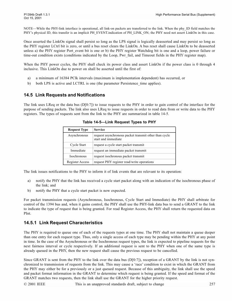
P1394b Draft 1.3.1 High Performance Serial Bus (Supplement)Oct 15, 2001
NOTEWhile the PHY-link interface is operational, all link-on packets are transferred to the link. When the phy_ID field matches thePHYs physical ID, this transfer is an implicit PH_EVENT.indication of PH_LINK_ON; the PHY need not assert LinkOn in this case.
Once asserted the LinkOn signal shall persist so long as the LPS signal is logically deasserted and may persist so long asthe PHY register LCtrl bit is zero, or until a bus reset clears the LinkOn. A bus reset shall cause LinkOn to be deassertedunless a) the PHY register Port_event bit is one or b) the PHY register Watchdog bit is one and a loop, power failure ortime-out condition exists (conditions indicated by the Loop, Pwr_fail, and Timeout fields in the PHY register map).
When the PHY power cycles, the PHY shall check its power class and assert LinkOn if the power class is 0 through 4inclusive. This LinkOn due to power on shall be asserted until the first of:
a) a minimum of 16384 PClk intervals (maximum is implementation dependent) has occurred, orb) both LPS is active and LCTRL is one (the parameter Persistence_time applies).
14.5 Link Requests and Notifications
The link uses LReq or the data bus (D[0:7]) to issue requests to the PHY in order to gain control of the interface for thepurpose of sending packets. The link also uses LReq to issue requests in order to read data from or write data to the PHYregisters. The types of requests sent from the link to the PHY are summarized in table 14-5.
The link issues notifications to the PHY to inform it of link events that are relevant to its operation:
a) notify the PHY that the link has received a cycle start packet along with an indication of the isochronous phase ofthe link; and
b) notify the PHY that a cycle start packet is now expected.
For packet transmission requests (Asynchronous, Isochronous, Cycle Start and Immediate) the PHY shall arbitrate forcontrol of the 1394 bus and, when it gains control, the PHY shall use the PHY-link data bus to send a GRANT to the linkto indicate the type of request that is being granted. For read Register Access, the PHY shall return the requested data onPInt.
14.5.1 Link Request Characteristics
The PHY is required to queue one of each of the requests types at one time. The PHY shall not maintain a queue deeperthan one entry for each request type. Thus, only a single access of each type may be pending within the PHY at any pointin time. In the case of the Asynchronous or the Isochronous request types, the link is expected to pipeline requests for thenext fairness interval or cycle respectively. If an additional request is sent to the PHY when one of the same type isalready queued in the PHY, then the new request shall cause the previous request to be cancelled.
Since GRANT is sent from the PHY to the link over the data bus (D[0:7]), reception of a GRANT by the link is not syn-chronized to transmission of requests from the link. This may cause a race condition to exist in which the GRANT fromthe PHY may either be for a previously or a just queued request. Because of this ambiguity, the link shall use the speedand packet format information in the GRANT to determine which request is being granted. If the speed and format of theGRANT matches two requests, then the link shall use the GRANT for the higher priority request.
Table 14-5Link Request Types to PHY
Request Type Service
Asynchronous request asynchronous packet transmit other than cycle start and immediate
Cycle Start request a cycle start packet transmit
Immediate request an immediate packet transmit
Isochronous request isochronous packet transmit
Register Access request PHY register read/write operations
© 2001 IEEE This is an unapproved standards draft, subject to change 257
High Performance Serial Bus (Supplement) P1394b Draft 1.3.1Oct 15, 2001
The PHY is allowed to change a request for which the link specifies no format into a Beta formatted request if the PHYknows that the packet will only travel over Beta connections. The PHY may determine this by noting that the speed of therequest is faster than the maximum Legacy path speed (determined during self-ID phase of the bus). If the PHY doesupgrade the request, it shall remember that the format of the original request was Unspecified and return this indicationin the GRANT so that the link may use this to help resolve any ambiguity in the GRANT.
If a GRANT is given to the link for any of the packet transfer request types, no requests of the same type shall be queuedin the PHY until the end of the packet transmission by the link. At the end of the packet, the link has the opportunity ofimmediately queuing another request including one of the same type by using the MORE_INFO cycle (seeclause 14.6.3.5). Until the first cycle in which the link releases the data bus, the PHY shall not queue a request that isreceived on LReq if that request is same as the current GRANT type. For example, if the link is transmitting an asynchro-nous data packet, the PHY shall not queue an Asynchronous request sent over LReq if that LReq is sent during the asyn-chronous data packet transmission. The PHY shall not check the request type until the stop bit is received at the end ofthe LReq.
Whenever the PHY-link interface is reset, or initialized, or when the PHY sends a Bus Status Transfer indicating that aSerial Bus reset has occurred, all pending transfer requests are cancelled in the PHY. The PHY also cancels all requestswhen a PH_RESTORE_NO_RESET is sent to indicate that a restore process has started on a PHY port. For all of theseevents, the PHY shall not queue any transfer request from the link except for Cycle Start until the PHY has completed theoperation and sent an unsolicited register 0 status transfer to the link.
14.5.1.1 Asynchronous Packet Transmit Requests
The link issues an Asynchronous type packet transmit request in order to transmit any asynchronous 1394 primary packet,or PHY packet. The link uses the request format described in clause 14.5.3 to issue an Asynchronous request.
Both links and PHYs observe the current fairness interval phase, either odd or even. The fairness interval phase is usedto allow the link to pipeline asynchronous transmit requests to the PHY. If the current fairness interval phase is even, thelink may issue a CURRENT or NEXT_ODD asynchronous transmit request. Similarly, if the current fairness intervalphase is odd, the link may issue either a CURRENT or NEXT_EVEN.
It is possible that the link will issue a NEXT_EVEN request on or about the time that the bus phase changes from odd toeven. In this case, the PHY shall interpret the request as a CURRENT request. Behavior for NEXT_ODD request is sim-ilar. It should be noted that if the link issues a NEXT_EVEN/NEXT_ODD request when the link is in the even/odd phase,the phase may change as the request is being sent to the PHY. This will prevent the PHY from converting the request toCURRENT which means that request will not be serviced until the next time the bus enters the even/odd phase. For thisreason the link should use CURRENT request to issue an even request in the even phase or an odd request during the oddphase rather than by issuing NEXT_EVEN requests in the even phase and NEXT_ODD requests in the odd phase.
The PHY provides notification of a fairness interval phase change via the appropriate Arbitration Reset Bus Status Trans-fer (see table 14-19). Upon receipt of this status transfer, the link updates its awareness of the current fairness intervalphase.
The link may only have one asynchronous transmit request pending in the PHY at any time. If a new asynchronous trans-mit request is issued by the link, it shall take precedence over the previous request. In this way, if a link has issued arequest for the next fairness interval (even or odd), and then determines that it has an additional asynchronous request thatmay be issued within the current fairness interval, it may issue a new asynchronous request for the current phase. Thisnew current request cancels the request for the next fairness interval, which can be re-issued by the link if appropriate.
If the link has issued a NEXT_EVEN or NEXT_ODD request and, before a matching GRANT is received, subsequentlyissues a CURRENT request, then when the asynchronous GRANT is received, if it matches the speed and format of theCURRENT request, then the link shall use the GRANT for the packet associated with the CURRENT request even if theGRANT also matches the speed and format of the NEXT_* request. The link may then reissue the request associated withthe previous NEXT_* request in the MORE_INFO cycle at the end of the packet transmission.
258 This is an unapproved standards draft, subject to change © 2001 IEEE
P1394b Draft 1.3.1 High Performance Serial Bus (Supplement)Oct 15, 2001
14.5.1.2 Cycle Start Packet Transmit Request
The link issues a request of type PH_CYC_START_REQ in order to transmit a cycle start primary packet. The link usesthe request format described in clause 14.5.3 to issue a PH_CYC_START_REQ request. The PHY shall not grant thisrequest if the node is not root. The request may remain pending in the PHY until the next bus reset.
14.5.1.3 Immediate Packet Transmit Request
The link issues a request of type PH_IMMED_REQ in order to transmit a packet without waiting for the normal arbitra-tion process. This request type is normally used by the link to transmit an acknowledge packet in response to a receivedpacket which was addressed to this node.
The link shall start sending the PH_IMMED_REQ to the PHY within eight LClk cycles after it receives the first quadletof an asynchronous packet that is addressed to the node or immediately after completing any LReq that may be inprogress at that time. If a subsequent header CRC error is detected, the link shall not drive the D[0:7] lines when the PHYgrants the link for the immediate request. After several cycles of inactivity, the PHY will regain control of the interface.
In order to avoid excessive delays in sending the PH_IMMED_REQ to the PHY, the link shall not start any request otherthan a PH_IMMED_REQ after receiving the packet format byte of a received packet. After determining that aPH_IMMED_REQ is not needed or after it is sent, then other LReqs are allowed.
The link is not allowed to send an acknowledge if the immediately preceding packet on the bus is not an asynchronouspacket addressed to the node. In some error conditions the PHY may grant the links immediate request when the link isnot allowed to send an acknowledge. This may occur when the node receives a packet with a CRC error in the header orif some other node erroneously concatenates a packet to the primary packet addressed to the node. In such case, the linkshall not drive the data bus. After several cycles of no activity on the data bus, the PHY will regain control of the inter-face and send a null packet on the Serial Bus. This error condition may result in multiple asynchronous packets being loston the bus (no acknowledgement).
14.5.1.4 Isochronous Packet Transmit Requests
The link issues a request of type Isochronous in order to transmit any isochronous 1394 primary packet. The link mayhave only one isochronous packet transmit request outstanding at any point in time. The link uses the request formatdescribed in clause 14.5.3 to issue an isochronous packet transmit request.
The link issues isochronous requests explicitly for either the odd or even isochronous phase. The operation of the isoch-ronous period phase is similar to that of the fairness interval phase. As with asynchronous requests, only one isochronoustransmit request from the link is stored by the PHY. Any new isochronous request shall cancel any previous isochronousrequest.
There is sufficient information in the isochronous grant issued by the PHY to the link in order for the link to determinewhich request is being granted by the PHY. If the GRANT matches two requests, then the link shall use the GRANT forthe higher priority request. It may then use a MORE_INFO cycle to reissue the other request at the end of the packet.
In order to insure that it generates the request in time, the link shall issue an isochronous request for the next interval suchthat it is pending at the cycle master before the end of the cycle start packet is sent. This requirement may be met in sev-eral ways, two of which are by sending the request at least 10us before the links cycle timer indicates the start of the nextisochronous period or by always appending an isochronous request for the next interval to the end of the last isochronouspacket sent in an interval.
After sending a first isochronous packet within an isochronous interval, all requests for subsequent isochronous packettransmission within that same interval shall be made in the MORE_INFO cycle at the end of each isochronous packet.
© 2001 IEEE This is an unapproved standards draft, subject to change 259

High Performance Serial Bus (Supplement) P1394b Draft 1.3.1Oct 15, 2001
Following a bus reset, the cycle master may issue a cycle start. If, after a bus reset, a node issues an isochronous requestwithin 1us of receiving the unsolicited register 0, then the isochronous request will be propagated to the cycle master intime to be recognized in that first isochronous interval.
14.5.1.5 PHY Register Read/Write Requests
The link issues PHY register read or write requests to gain access to the PHYs internal register space. The PHY addressspace is addressable via a 4-bit address, allowing for 16 directly addressable register locations, each a single byte. Thelink issues PHY register read and write requests using the request format described in clause 14.5.3.
The link issues a PHY register read request to instruct the PHY to return the contents of one of its internal registers via astatus transfer. The link specifies the PHY address as part of the request. The link shall not issue a further PHY registerread request until the first has been completed via a status transfer. The PHY shall ignore further PHY register readrequests until the first has been completed. PHY register reads may be initiated at any time.
The link issues a PHY register write request to write new contents to one of the PHYs internal registers. The link sup-plies the PHY register address and the write data as part of the request. The PHY shall write the data content immediatelyto the appropriate PHY register. PHY register writes shall not be initiated by the link while a PHY register read is pend-ing. Any PHY register write which is issued while a register read is pending shall be ignored by the PHY.
14.5.1.6 Restore
When a port on the PHY of a Nephew node is in the Standby state, the link may initiate a restore operation on that portby issuing any packet transfer request to the PHY. A restore may also be initiated by the Uncle.
When the PHY begins the restore operation on the port, it shall send a PH_RESTORE_NO_RESET indication to the linkand cancel all pending packet transfer requests. Later, when the PHY receives the Restore PHY packet from the Uncle, itshall send a PH_RESTORE_RESET if the Restore PHY packet indicates that a reset occurred while the PHY was instandby. The PHY shall complete the restore operation with the initialization completion sequence defined inclause 14.3.4.1.
It is possible that a Bus Reset indication will be received in a Bus Status Transfer before the Restore completes. If thisoccurs, then the PHY and link shall follow the sequence described in clause 14.8.1.1.
14.5.2 Link Notifications
The link issues notifications to the PHY Device to inform it of events that have been observed or detected that are rele-vant to the PHYs operation. Link notifications take place as soon as possible following the links detection of the rele-vant event. link notifications are issued using the same format as requests, described in clause 14.5.3.
14.5.2.1 Cycle Start Received Notification
Any link that is capable of making an isochronous request shall issue a link request to notify the PHY when the link hasreceived a cycle start packet. This notification shall be in the form of a link request of either PH_ISOCH_PHASE_EVENor PH_ISOCH_PHASE_ODD. This insures that the PHY knows the isochronous phase that the link is using and protectsagainst problems should the Cycle Start token not be received by the PHY. The link notification is issued using the formatdescribed in clause 14.5.3.
The link shall start sending the notification of a received cycle start no later than eight LClk cycles after the quadlet con-taining the CRC of the cycle start packet is received. It is not necessary that the CRC of this packet be verified before thisnotification is sent. It is, however, necessary that the link check that the packet has a Tcode of 0x8 and is more that twoquadlets long before sending the PH_ISOCH_PHASE_* notification.
260 This is an unapproved standards draft, subject to change © 2001 IEEE

P1394b Draft 1.3.1 High Performance Serial Bus (Supplement)Oct 15, 2001
The simplified qualification of the cycle start packet allowed here is not sufficient for the link to fully qualify the start ofan isochronous interval. The CRC of the cycle start packet shall be verified or the link shall receive a Bus Status Transferindicating a Cycle Start before the link may use a grant to send an isochronous packet.
14.5.2.2 Cycle Start Due Notification
The link may issue a PH_CYCLE_START_DUE when it has determined that a cycle start packet is due to be received overthe Serial Bus. This information is useful to the PHY to allow correct operation of border-related functionality. If pro-vided, the link notification is issued using the format described in clause 14.5.3.
NOTEIt is preferred but not required that this notification be provided by all links that are compliant with this standard.
14.5.3 Link Request and Notification Format
The link uses the following signalling format to issue requests and notifications to the PHY. Link requests and notifica-tions are issued serially over the LReq interface pin. The LReq signal is always driven by the link. The link is responsiblefor ensuring that all information transferred using the LReq signal follows the format outlined in this section. If the linkissues a request or notification outside of this defined specification, such a request shall be ignored by the PHY.
If LClk has been stopped, the link may not issue any requests or notifications on LReq until at least 5 LClk cycles havebeen sent.
14.5.3.1 Request and Notification Signalling Format
The link request begins with a START bit (always a 1), followed by a mandatory 4-bit link request type field, RT[0:3].An optional single bit Request Format field, RFMT, then follows. Depending on the link request type, there may be a fol-lowing 4-bit address (RS[0:3]) and a further 8-bit data field (RD[0:7]). The link request is completed with a mandatoryEND bit (always a 0). Following the END bit, another link request may be issued immediately.
The link Request Type field (RT[0:3]) specifies the type of link request or notification which follows. The link RequestType field is mandatory for all link requests. Most link requests require additional information to be transferred in theform of request parameters. The PHY determines from the RT[0:3] value if such parameters will follow in accordancewith table 14-6. For requests to use the Serial Bus for transfer of data, the Request Type (RT[0:3]) field is followed by the
NOTEeach cell in the link Request Format represents one LClk cycle time
Figure 14-7Link Request Format
LReq ..... ..... .....RT[0] RT[3]RS[0] / RS[3] /
RD[0] RD[7]
START
BIT
LINK REQUEST
TYPE
LINK REQUEST SPEED or
PHY REGISTER ADDRESS
PHY REGISTER
DATA
ENDBIT
RFMT
REQUEST
FORMAT
(as required) (as required) (as required)
RA[0] RA[3]
© 2001 IEEE This is an unapproved standards draft, subject to change 261
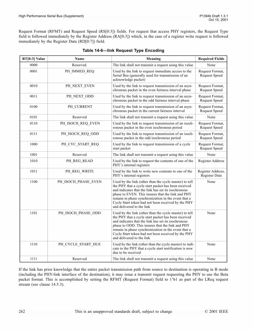
High Performance Serial Bus (Supplement) P1394b Draft 1.3.1Oct 15, 2001
Request Format (RFMT) and Request Speed (RS[0:3]) fields. For request that access PHY registers, the Request Typefield is followed immediately by the Register Address (RA[0:3]) which, in the case of a register write request is followedimmediately by the Register Data (RD[0:7]) field.
If the link has prior knowledge that the entire packet transmission path from source to destination is operating in B mode(including the PHY-link interface of the destination), it may issue a transmit request requesting the PHY to use the Betapacket format. This is accomplished by setting the RFMT (Request Format) field to 1b1 as part of the LReq requeststream (see clause 14.5.3).
Table 14-6link Request Type Encoding
RT[0:3] Value Name Meaning Required Fields
0000 Reserved. The link shall not transmit a request using this value None
0001 PH_IMMED_REQ Used by the link to request immediate access to the Serial Bus (generally used for transmission of an acknowledge packet)
Request Format, Request Speed
0010 PH_NEXT_EVEN Used by the link to request transmission of an asyn-chronous packet in the even fairness interval phase
Request Format, Request Speed
0011 PH_NEXT_ODD Used by the link to request transmission of an asyn-chronous packet in the odd fairness interval phase
Request Format, Request Speed
0100 PH_CURRENT Used by the link to request transmission of an asyn-chronous packet in the current fairness interval
Request Format, Request Speed
0101 Reserved The link shall not transmit a request using this value None
0110 PH_ISOCH_REQ_EVEN Used by the link to request transmission of an isoch-ronous packet in the even isochronous period
Request Format, Request Speed
0111 PH_ISOCH_REQ_ODD Used by the link to request transmission of an isoch-ronous packet in the odd isochronous period
Request Format, Request Speed
1000 PH_CYC_START_REQ Used by the link to request transmission of a cycle start packet
Request Format, Request Speed
1001 Reserved The link shall not transmit a request using this value None
1010 PH_REG_READ Used by the link to request the contents of one of the PHYs internal registers
Register Address
1011 PH_REG_WRITE Used by the link to write new contents to one of the PHYs internal registers
Register Address,Register Data
1100 PH_ISOCH_PHASE_EVEN Used by the link (other than the cycle master) to tell the PHY that a cycle start packet has been received and indicates that the link has set its isochronous phase to EVEN. This insures that the link and PHY remain in phase synchronization in the event that a Cycle Start token had not been received by the PHY and delivered to the link
None
1101 PH_ISOCH_PHASE_ODD Used by the link (other than the cycle master) to tell the PHY that a cycle start packet has been received and indicates that the link has set its isochronous phase to ODD. This insures that the link and PHY remain in phase synchronization in the event that a Cycle Start token had not been received by the PHY and delivered to the link
None
1110 PH_CYCLE_START_DUE Used by the link (other than the cycle master) to indi-cate to the PHY that a cycle start notification is now due to be received
None
1111 Reserved The link shall not transmit a request using this value None
262 This is an unapproved standards draft, subject to change © 2001 IEEE
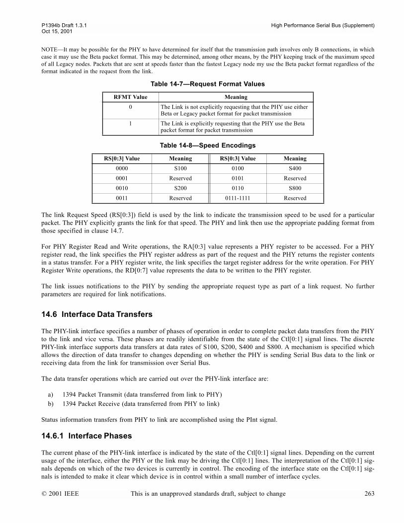
P1394b Draft 1.3.1 High Performance Serial Bus (Supplement)Oct 15, 2001
NOTEIt may be possible for the PHY to have determined for itself that the transmission path involves only B connections, in whichcase it may use the Beta packet format. This may be determined, among other means, by the PHY keeping track of the maximum speedof all Legacy nodes. Packets that are sent at speeds faster than the fastest Legacy node my use the Beta packet format regardless of theformat indicated in the request from the link.
The link Request Speed (RS[0:3]) field is used by the link to indicate the transmission speed to be used for a particularpacket. The PHY explicitly grants the link for that speed. The PHY and link then use the appropriate padding format fromthose specified in clause 14.7.
For PHY Register Read and Write operations, the RA[0:3] value represents a PHY register to be accessed. For a PHYregister read, the link specifies the PHY register address as part of the request and the PHY returns the register contentsin a status transfer. For a PHY register write, the link specifies the target register address for the write operation. For PHYRegister Write operations, the RD[0:7] value represents the data to be written to the PHY register.
The link issues notifications to the PHY by sending the appropriate request type as part of a link request. No furtherparameters are required for link notifications.
14.6 Interface Data Transfers
The PHY-link interface specifies a number of phases of operation in order to complete packet data transfers from the PHYto the link and vice versa. These phases are readily identifiable from the state of the Ctl[0:1] signal lines. The discretePHY-link interface supports data transfers at data rates of S100, S200, S400 and S800. A mechanism is specified whichallows the direction of data transfer to changes depending on whether the PHY is sending Serial Bus data to the link orreceiving data from the link for transmission over Serial Bus.
The data transfer operations which are carried out over the PHY-link interface are:
a) 1394 Packet Transmit (data transferred from link to PHY)b) 1394 Packet Receive (data transferred from PHY to link)
Status information transfers from PHY to link are accomplished using the PInt signal.
14.6.1 Interface Phases
The current phase of the PHY-link interface is indicated by the state of the Ctl[0:1] signal lines. Depending on the currentusage of the interface, either the PHY or the link may be driving the Ctl[0:1] lines. The interpretation of the Ctl[0:1] sig-nals depends on which of the two devices is currently in control. The encoding of the interface state on the Ctl[0:1] sig-nals is intended to make it clear which device is in control within a small number of interface cycles.
Table 14-7Request Format Values
RFMT Value Meaning
0 The Link is not explicitly requesting that the PHY use either Beta or Legacy packet format for packet transmission
1 The Link is explicitly requesting that the PHY use the Beta packet format for packet transmission
Table 14-8Speed Encodings
RS[0:3] Value Meaning RS[0:3] Value Meaning
0000 S100 0100 S400
0001 Reserved 0101 Reserved
0010 S200 0110 S800
0011 Reserved 0111-1111 Reserved
© 2001 IEEE This is an unapproved standards draft, subject to change 263
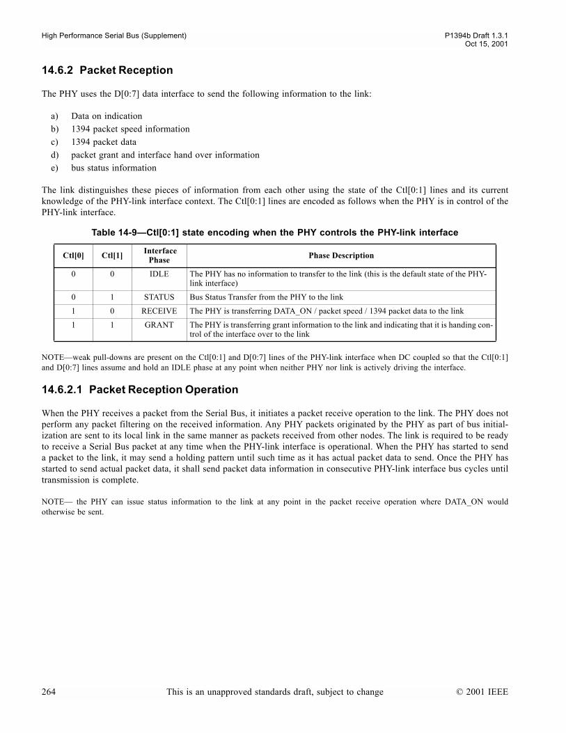
High Performance Serial Bus (Supplement) P1394b Draft 1.3.1Oct 15, 2001
14.6.2 Packet Reception
The PHY uses the D[0:7] data interface to send the following information to the link:
a) Data on indicationb) 1394 packet speed informationc) 1394 packet datad) packet grant and interface hand over informatione) bus status information
The link distinguishes these pieces of information from each other using the state of the Ctl[0:1] lines and its currentknowledge of the PHY-link interface context. The Ctl[0:1] lines are encoded as follows when the PHY is in control of thePHY-link interface.
NOTEweak pull-downs are present on the Ctl[0:1] and D[0:7] lines of the PHY-link interface when DC coupled so that the Ctl[0:1]and D[0:7] lines assume and hold an IDLE phase at any point when neither PHY nor link is actively driving the interface.
14.6.2.1 Packet Reception Operation
When the PHY receives a packet from the Serial Bus, it initiates a packet receive operation to the link. The PHY does notperform any packet filtering on the received information. Any PHY packets originated by the PHY as part of bus initial-ization are sent to its local link in the same manner as packets received from other nodes. The link is required to be readyto receive a Serial Bus packet at any time when the PHY-link interface is operational. When the PHY has started to senda packet to the link, it may send a holding pattern until such time as it has actual packet data to send. Once the PHY hasstarted to send actual packet data, it shall send packet data information in consecutive PHY-link interface bus cycles untiltransmission is complete.
NOTE the PHY can issue status information to the link at any point in the packet receive operation where DATA_ON wouldotherwise be sent.
Table 14-9Ctl[0:1] state encoding when the PHY controls the PHY-link interface
Ctl[0] Ctl[1] Interface Phase Phase Description
0 0 IDLE The PHY has no information to transfer to the link (this is the default state of the PHY-link interface)
0 1 STATUS Bus Status Transfer from the PHY to the link
1 0 RECEIVE The PHY is transferring DATA_ON / packet speed / 1394 packet data to the link
1 1 GRANT The PHY is transferring grant information to the link and indicating that it is handing con-trol of the interface over to the link
264 This is an unapproved standards draft, subject to change © 2001 IEEE

P1394b Draft 1.3.1 High Performance Serial Bus (Supplement)Oct 15, 2001
14.6.2.2 Packet Reception Timing
14.6.2.3 Packet Reception Description
The steps for packet reception are:
a) The PHY indicates that it has packet information to send to the link by asserting RECEIVE on the Ctl[0:1] lines.If there is no packet data ready for transfer to the link at that time, the PHY shall indicate this to the link byasserting DATA_ON encoding on the D[0:7] lines. The PHY shall maintain this until such time as data isavailable. The PHY may indicate DATA_ON for an unlimited period.
b) The PHY indicates the speed and format of the packet data by indicating the format and speed of the receivedpacket. This is asserted on D[0:7] for one cycle while RECEIVE is asserted on the Ctl[0:1] lines.
c) The PHY transfers packet information to the link on the D[0:7] lines during successive cycles while continuing toassert RECEIVE on the Ctl[0:1] lines until the transfer is complete
d) The PHY asserts IDLE on the Ctl[0:1] lines and drives the D[0:7] lines to 0 to indicate the completion of thepacket receive operation.
If the speed of the received packet exceeds S800 the PHY shall send DATA_ON indications for the duration of the packet.
When DATA_NULL is sent on the Serial Bus, the PHY shall send a DATA_ON indication on the PHY-link interface.
NOTEB0 - BN represent the information bytes transferred from the PHY to the link. See clause 14.7 for a data format description.
Figure 14-8PHY-link Packet Receive Operation
Table 14-10Receive Packet SPD encoding
D[0:7] during SPD cycle Receive Packet Speed and Format
0000 0000 S100 Legacy
0000 0001 S100 Beta
0000 0100 S200 Legacy
0000 0101 S200 Beta
0000 1000 S400 Legacy
0000 1001 S400 Beta
0000 1101 S800 Beta
1111 1111 DATA_ON
Other Values reserved
00 10 10 10 10 10 00Ctl[0:1]
00 FF FF SPD B0 B1 00D[0:7] ..
..
DATA_ON INDICATION
10
BN.....
..... 00
00
RECEIVE SPEED
RECEIVE PACKET DATA
..
..01
ST
(WITH STATUS INDICATIONAS REQUIRED)
..
..
..
..
© 2001 IEEE This is an unapproved standards draft, subject to change 265

High Performance Serial Bus (Supplement) P1394b Draft 1.3.1Oct 15, 2001
NOTEthese encodings supersede the encodings specified in IEEE 1394a-2000.
14.6.2.4 Inter-Packet Spacing for Received Packets
Between any two received 1394 primary packets or PHY packets there will be at least four PClks of non-packet data timeon the PHY-link interface.
14.6.3 Packet Transmission
The link uses the D[0:7] interface to send the following information to the PHY:
a) Interface Hold indicationb) 1394 Packet Datac) Link Requestsd) Interface hand over information
The PHY distinguishes these pieces of information using the state of the Ctl[0:1] lines and its current knowledge of thePHY-link interface context. The Ctl[0:1] lines are encoded as follows when the link is in control of the PHY-link inter-face.
NOTEweak pull-downs are present on the Ctl[0:1] and D[0:7] pins of the PHY-link interface when DC coupled so that the Ctl[0:1]and D[0:7] lines assume and hold an IDLE phase at any point when neither PHY nor link is actively driving the interface.
14.6.3.1 Packet Transmit Operation
When the link requests packet transmit services from the PHY, the PHY performs a Serial Bus arbitration. When accessto the Serial Bus is granted to the PHY, the PHY propagates this grant to the link. The link then assumes ownership of thePHY-link interface data and control buses. The link may transmit bus holding symbols while it prepares data for transmis-sion. The link then transmits the Serial Bus packet data until such time as it has completed its packet transmit operation.Once the link has commenced transmitting the Serial Bus packet information, it is required to continue to do so in con-secutive PHY-link interface bus cycles until transmission is complete. When the link has completed its packet transmis-sion, it may optionally provide a further link request on the data bus, and shall then hand the PHY-link interface back tothe PHY. It should be noted that the PHY may not immediately grant a request made in a MORE_INFO cycle.
Table 14-11Ctl[0:1] state encoding when the link controls the PHY-link interface
Ctl[0] Ctl[1] Interface Phase Phase Description
0 0 IDLE The link has completed packet transmission and is handing the interface back to the PHY
0 1 TRANSMIT The link is transmitting packet information to the PHY
1 0 Reserved Reserved. The link shall not generate this Ctl pattern
1 1 HOLD/MORE_INFO
When asserted at the start of a packet transmission, indicates that the link is holding the PHY-link interface while it is preparing data for transmission; when asserted at the end of a packet transmission, indicates that D[0:7] contains information on the packet being com-pleted, and an embedded link request for another packet transmission
266 This is an unapproved standards draft, subject to change © 2001 IEEE

P1394b Draft 1.3.1 High Performance Serial Bus (Supplement)Oct 15, 2001
14.6.3.2 PHY-link Packet Transmit Timing
The packet transmission timing is described in the following timing diagram
14.6.3.3 PHY-link Packet Transmission Description
The steps for packet transmission are:
a) After at least one cycle of IDLE or STATUS, the PHY indicates that it is transferring ownership of the interfaceto the link by asserting GRANT on the Ctl[0:1] lines for one cycle while driving the appropriate GNT value onthe D[0:7] lines (see table 14-13). The PHY then pre-conditions the Ctl[0:1] and D[0:7] lines by driving them tozero for one cycle followed by releasing the Ctl[0:1] and D[0:7] lines to a high impedance state.
NOTEB0 - BN represent the information bytes transferred from the link to the PHY. See clause 14.7 for a data format description.
Figure 14-9PHY-link Packet Transmit Operation, including optional HOLD cycles
00 11 00 ZZ ZZ ZZ ZZ ZZ ZZPHY Ctl[0:1]
00 GT 00 ZZ ZZ ZZ ZZ ZZ ZZPHY D[0:7]
ZZ ZZ ZZ ZZ ZZ 11 11 01 01LINK Ctl[0:1]
ZZ ZZ ZZ ZZ ZZ 00 00 B0 B1LINK D[0:7]
.....
.....
ZZ ZZ ZZ ZZ ZZ ZZ 00 00 00PHY Ctl[0:1]
ZZ ZZ ZZ ZZ ZZ ZZ 00 00 00PHY D[0:7]
01 01 11 00 ZZ ZZ ZZ ZZ ZZLINK Ctl[0:1]
BN-1 BN AI 00 ZZ ZZ ZZ ZZ ZZLINK D[0:7]
.....
.....
.....
.....
.....
.....
...
...
...
...
...
...
...
...
.....
.....
.....
.....
INTERFACE GRANT and RELEASE
INTERFACE HOLD DATA TRANSFER
DATA TRANSFER INTERFACE RELEASE
INTERFACE IDLE
OPTIONAL ADDITIONAL INFORMATION
© 2001 IEEE This is an unapproved standards draft, subject to change 267

High Performance Serial Bus (Supplement) P1394b Draft 1.3.1Oct 15, 2001
b) After the link observes one cycle of zeros on Ctl[0:1] it shall wait one additional cycle (as measured by the LClk)before driving the Ctl and Data buses. It shall indicate that it has packet data to transmit by asserting HOLD orTRANSMIT on Ctl[0:1]. If the link drives HOLD on Ctl[0:1] while it prepares data for transmission, it shall driveD[0:7] to 0. The link shall drive HOLD for no more that MAX_HOLD. If the link does not have any data totransmit or wishes to abdicate its transmit opportunity, it shall not drive any value on the Ctl[0:1] or D[0:7] lines.
c) The PHY monitors the Ctl[0:1] lines to determine if the link has completed the interface hand over. If the PHYhas not detected either HOLD or TRANSMIT phases within 8 PClk cycles, the PHY shall assume that the link hasabdicated its transmission opportunity and shall assume control of the interface by driving Ctl[0:1] to IDLE andD[0:7] to 0.
d) The link asserts TRANSMIT on the Ctl[0:1] lines when it is transmitting packet data on the D[0:7] lines.e) After the last byte of the packet being transmitted, the link may provide additional information to the PHY. The
link indicates this by asserting MORE_INFO on the Ctl[0:1] lines while driving the relevant packet information(MORE_INFO values defined in table 14-15 through table 14-18) on the D[0:7] lines.
f) The link terminates a packet transmission by asserting IDLE on the Ctl[0:1] lines for one cycle while driving zeroon the D[0:7] lines. The link then releases the Ctl[0:1] and D[0:7] lines to a high-impedance state. The link mayrelease the interface without sending any data.
g) When the PHY detects the IDLE cycle from the link, it shall regain ownership of the interface by driving IDLEon the Ctl[0:1] lines and zero on the D[0:7] lines.
NOTE If the link does not provide any additional information at the end of packet transmission, the MORE_INFO phaseis skipped; the link drives IDLE on the Ctl[0:1] lines and zero on the D[0:7] for one cycle before releasing the signals toa high-impedance state.
14.6.3.4 Transmit Grant Types
The PHY indicates to the link during the GRANT cycle which type of grant is being issued. This indication includes thegrant type as well as the grant speed. The link shall only use the bus grant for transmitting the granted packet type. Thelink shall transmit a granted packet type only if its request type exactly matches the granted speed and the granted format.
Table 14-12Format Type During Grant Cycle
D[0] Value during GRANT cycle Format
0 Unspecified
1 Beta
Table 14-13Grant Type values during Grant Cycle
D[1:3] Value during GRANT cycle Grant Type
000 Reserved
001 Reserved
010 Isochronous Grant
011 Reserved
100 Reserved
101 Asynchronous Grant
110 Cycle Start Grant
111 Immediate Grant
268 This is an unapproved standards draft, subject to change © 2001 IEEE
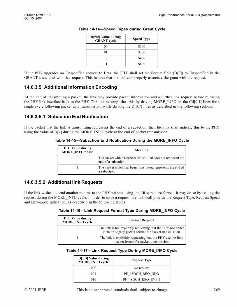
P1394b Draft 1.3.1 High Performance Serial Bus (Supplement)Oct 15, 2001
If the PHY upgrades an Unspecified request to Beta, the PHY shall set the Format field (D[0]) to Unspecified in theGRANT associated with that request. This insures that the link can properly associate the grant with the request.
14.6.3.5 Additional Information Encoding
At the end of transmitting a packet, the link may provide packet information and a further link request before releasingthe PHY-link interface back to the PHY. The link accomplishes this by driving MORE_INFO on the Ctl[0:1] lines for asingle cycle following packet data transmission, while driving the D[0:7] lines as described in the following sections
14.6.3.5.1 Subaction End Notification
If the packet that the link is transmitting represents the end of a subaction, then the link shall indicate this to the PHYusing the value of D[4] during the MORE_INFO cycle at the end of packet transmission.
14.6.3.5.2 Additional link Requests
If the link wishes to send another request to the PHY without using the LReq request format, it may do so by issuing therequest during the MORE_INFO cycle. In order to issue a request, the link shall provide the Request Type, Request Speedand Beta-mode indication, as described in the following tables
Table 14-14Speed Types during Grant Cycle
D[5:6] Value during GRANT cycle Speed Type
00 S100
01 S200
10 S400
11 S800
Table 14-15Subaction End Notification During the MORE_INFO Cycle
D[4] Value during MORE_INFO phase Meaning
0 The packet which has been transmitted does not represent the end of a subaction
1 The packet which has been transmitted represents the end of a subaction
Table 14-16Link Request Format Type During MORE_INFO Cycle
D[0] Value during MORE_INFO cycle Format Request
0 The link is not explicitly requesting that the PHY use either Beta or Legacy packet format for packet transmission
1 The link is explicitly requesting that the PHY use the Beta packet format for packet transmission
Table 14-17Link Request Type During MORE_INFO Cycle
D[1:3] Value during MORE_INFO cycle Request Type
000 No request
001 PH_ISOCH_REQ_ODD
010 PH_ISOCH_REQ_EVEN
© 2001 IEEE This is an unapproved standards draft, subject to change 269

High Performance Serial Bus (Supplement) P1394b Draft 1.3.1Oct 15, 2001
14.7 Format of Received and Transmitted Data
This specification allows the PHY and link to transfer data to each other at S100, S200, S400 and S800 on the parallelPHY-link interface.
The discrete PHY-link interface operates in a single clocking mode which is 98.304 MHz PClk/LClk with single-edgeclocking.
Data transfers between the PHY and link are accomplished by appropriate padding of the lower rate data as described inthe following sections. Data on the D[0:7] signal lines should be latched by the receiving device at the end of the firstcycle in a repeating series for data transfers at S400 and below. The transmitting device should drive the same data onD[0:7] for all cycles of a repeating series.
PClk and LClk both run at 98.304 MHz ±100 ppm. Data transfers take place on the rising edge of PClk and LClk. LReqrequests and PInt status notifications are transferred only on the rising edge of LClk and PClk respectively.
NOTEIn the following diagrams, the values shown on D[0:7] are those which would be seen on an undifferentiated interface. In thecase of a differentiated interface, the transmitting device drives the D[0:7] signal lines for only the first cycle of a repeated series, andthe D[0:7] signals are not driven for the remainder of the byte time.
011 PH_CURRENT
100 PH_NEXT_EVEN
101 PH_NEXT_ODD
110 PH_CYC_START_REQ
111 Reserved
Table 14-18Link Request Speed During MORE_INFO Cycle
D[5:6] Value during MORE_INFO cycle
link Request
Speed
00 S100
01 S200
10 S400
11 S800
Table 14-17Link Request Type During MORE_INFO Cycle
D[1:3] Value during MORE_INFO cycle Request Type
270 This is an unapproved standards draft, subject to change © 2001 IEEE
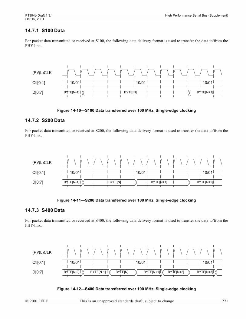
P1394b Draft 1.3.1 High Performance Serial Bus (Supplement)Oct 15, 2001
14.7.1 S100 Data
For packet data transmitted or received at S100, the following data delivery format is used to transfer the data to/from thePHY-link.
14.7.2 S200 Data
For packet data transmitted or received at S200, the following data delivery format is used to transfer the data to/from thePHY-link.
14.7.3 S400 Data
For packet data transmitted or received at S400, the following data delivery format is used to transfer the data to/from thePHY-link.
Figure 14-10S100 Data transferred over 100 MHz, Single-edge clocking
Figure 14-11S200 Data transferred over 100 MHz, Single-edge clocking
Figure 14-12S400 Data transferred over 100 MHz, Single-edge clocking
(P)/(L)CLK
Ctl[0:1]
D[0:7]
10/01 10/01 10/01
BYTE[N-1] BYTE[N+1]BYTE[N]
(P)/(L)CLK
Ctl[0:1]
D[0:7]
10/01 10/01 10/01
BYTE[N-1] BYTE[N+2]BYTE[N] BYTE[N+1]
(P)/(L)CLK
Ctl[0:1]
D[0:7]
10/01 10/01 10/01
BYTE[N-2] BYTE[N+3]BYTE[N-1] BYTE[N] BYTE[N+1] BYTE[N+2]
© 2001 IEEE This is an unapproved standards draft, subject to change 271
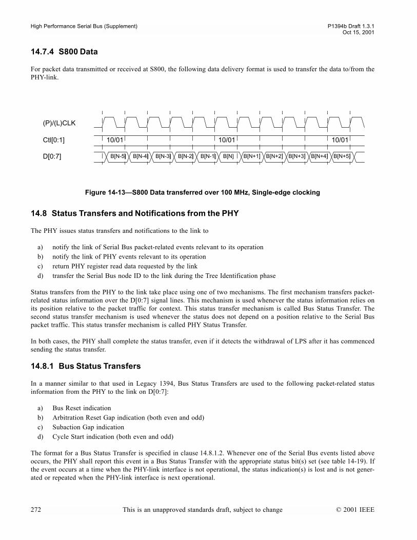
High Performance Serial Bus (Supplement) P1394b Draft 1.3.1Oct 15, 2001
14.7.4 S800 Data
For packet data transmitted or received at S800, the following data delivery format is used to transfer the data to/from thePHY-link.
14.8 Status Transfers and Notifications from the PHY
The PHY issues status transfers and notifications to the link to
a) notify the link of Serial Bus packet-related events relevant to its operationb) notify the link of PHY events relevant to its operationc) return PHY register read data requested by the linkd) transfer the Serial Bus node ID to the link during the Tree Identification phase
Status transfers from the PHY to the link take place using one of two mechanisms. The first mechanism transfers packet-related status information over the D[0:7] signal lines. This mechanism is used whenever the status information relies onits position relative to the packet traffic for context. This status transfer mechanism is called Bus Status Transfer. Thesecond status transfer mechanism is used whenever the status does not depend on a position relative to the Serial Buspacket traffic. This status transfer mechanism is called PHY Status Transfer.
In both cases, the PHY shall complete the status transfer, even if it detects the withdrawal of LPS after it has commencedsending the status transfer.
14.8.1 Bus Status Transfers
In a manner similar to that used in Legacy 1394, Bus Status Transfers are used to the following packet-related statusinformation from the PHY to the link on D[0:7]:
a) Bus Reset indicationb) Arbitration Reset Gap indication (both even and odd)c) Subaction Gap indicationd) Cycle Start indication (both even and odd)
The format for a Bus Status Transfer is specified in clause 14.8.1.2. Whenever one of the Serial Bus events listed aboveoccurs, the PHY shall report this event in a Bus Status Transfer with the appropriate status bit(s) set (see table 14-19). Ifthe event occurs at a time when the PHY-link interface is not operational, the status indication(s) is lost and is not gener-ated or repeated when the PHY-link interface is next operational.
Figure 14-13S800 Data transferred over 100 MHz, Single-edge clocking
(P)/(L)CLK
Ctl[0:1]
D[0:7]
10/01 10/01 10/01
B[N-5] B[N-4] B[N-3] B[N-2] B[N-1] B[N] B[N+1] B[N+2] B[N+3] B[N+4] B[N+5]
272 This is an unapproved standards draft, subject to change © 2001 IEEE
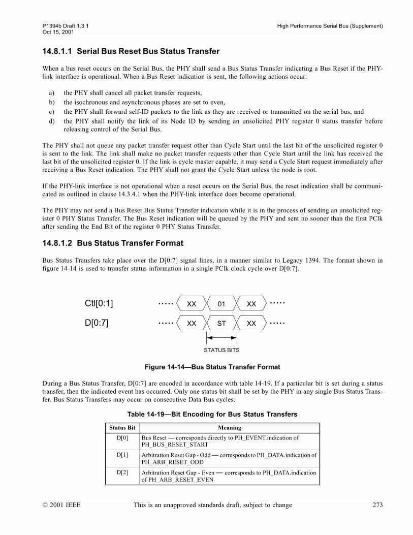
P1394b Draft 1.3.1 High Performance Serial Bus (Supplement)Oct 15, 2001
14.8.1.1 Serial Bus Reset Bus Status Transfer
When a bus reset occurs on the Serial Bus, the PHY shall send a Bus Status Transfer indicating a Bus Reset if the PHY-link interface is operational. When a Bus Reset indication is sent, the following actions occur:
a) the PHY shall cancel all packet transfer requests, b) the isochronous and asynchronous phases are set to even,c) the PHY shall forward self-ID packets to the link as they are received or transmitted on the serial bus, andd) the PHY shall notify the link of its Node ID by sending an unsolicited PHY register 0 status transfer before
releasing control of the Serial Bus.
The PHY shall not queue any packet transfer request other than Cycle Start until the last bit of the unsolicited register 0is sent to the link. The link shall make no packet transfer requests other than Cycle Start until the link has received thelast bit of the unsolicited register 0. If the link is cycle master capable, it may send a Cycle Start request immediately afterreceiving a Bus Reset indication. The PHY shall not grant the Cycle Start unless the node is root.
If the PHY-link interface is not operational when a reset occurs on the Serial Bus, the reset indication shall be communi-cated as outlined in clause 14.3.4.1 when the PHY-link interface does become operational.
The PHY may not send a Bus Reset Bus Status Transfer indication while it is in the process of sending an unsolicited reg-ister 0 PHY Status Transfer. The Bus Reset indication will be queued by the PHY and sent no sooner than the first PClkafter sending the End Bit of the register 0 PHY Status Transfer.
14.8.1.2 Bus Status Transfer Format
Bus Status Transfers take place over the D[0:7] signal lines, in a manner similar to Legacy 1394. The format shown infigure 14-14 is used to transfer status information in a single PClk clock cycle over D[0:7].
During a Bus Status Transfer, D[0:7] are encoded in accordance with table 14-19. If a particular bit is set during a statustransfer, then the indicated event has occurred. Only one status bit shall be set by the PHY in any single Bus Status Trans-fer. Bus Status Transfers may occur on consecutive Data Bus cycles.
Figure 14-14Bus Status Transfer Format
Table 14-19Bit Encoding for Bus Status Transfers
Status Bit Meaning
D[0] Bus Reset corresponds directly to PH_EVENT.indication of PH_BUS_RESET_START
D[1] Arbitration Reset Gap - Odd corresponds to PH_DATA.indication of PH_ARB_RESET_ODD
D[2] Arbitration Reset Gap - Even corresponds to PH_DATA.indication of PH_ARB_RESET_EVEN
Ctl[0:1] XX XX
STATUS BITS
D[0:7]
01
XX XXST
.....
..........
.....
© 2001 IEEE This is an unapproved standards draft, subject to change 273
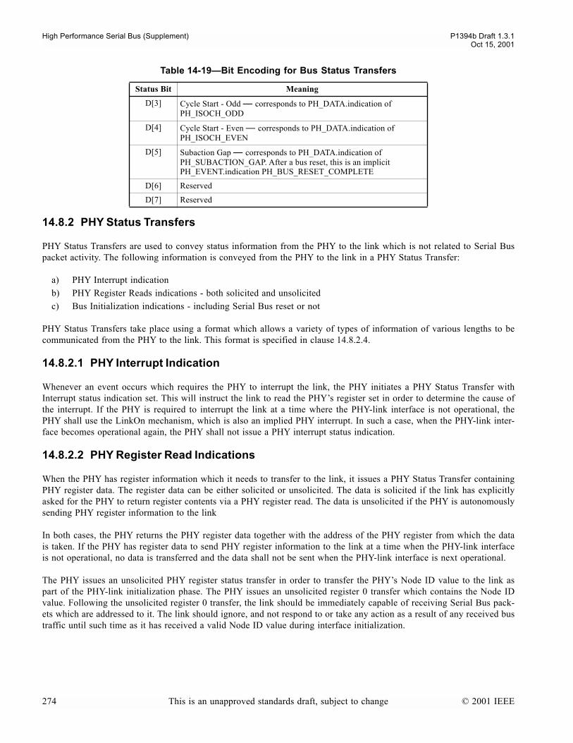
High Performance Serial Bus (Supplement) P1394b Draft 1.3.1Oct 15, 2001
14.8.2 PHY Status Transfers
PHY Status Transfers are used to convey status information from the PHY to the link which is not related to Serial Buspacket activity. The following information is conveyed from the PHY to the link in a PHY Status Transfer:
a) PHY Interrupt indicationb) PHY Register Reads indications - both solicited and unsolicitedc) Bus Initialization indications - including Serial Bus reset or not
PHY Status Transfers take place using a format which allows a variety of types of information of various lengths to becommunicated from the PHY to the link. This format is specified in clause 14.8.2.4.
14.8.2.1 PHY Interrupt Indication
Whenever an event occurs which requires the PHY to interrupt the link, the PHY initiates a PHY Status Transfer withInterrupt status indication set. This will instruct the link to read the PHYs register set in order to determine the cause ofthe interrupt. If the PHY is required to interrupt the link at a time where the PHY-link interface is not operational, thePHY shall use the LinkOn mechanism, which is also an implied PHY interrupt. In such a case, when the PHY-link inter-face becomes operational again, the PHY shall not issue a PHY interrupt status indication.
14.8.2.2 PHY Register Read Indications
When the PHY has register information which it needs to transfer to the link, it issues a PHY Status Transfer containingPHY register data. The register data can be either solicited or unsolicited. The data is solicited if the link has explicitlyasked for the PHY to return register contents via a PHY register read. The data is unsolicited if the PHY is autonomouslysending PHY register information to the link
In both cases, the PHY returns the PHY register data together with the address of the PHY register from which the datais taken. If the PHY has register data to send PHY register information to the link at a time when the PHY-link interfaceis not operational, no data is transferred and the data shall not be sent when the PHY-link interface is next operational.
The PHY issues an unsolicited PHY register status transfer in order to transfer the PHYs Node ID value to the link aspart of the PHY-link initialization phase. The PHY issues an unsolicited register 0 transfer which contains the Node IDvalue. Following the unsolicited register 0 transfer, the link should be immediately capable of receiving Serial Bus pack-ets which are addressed to it. The link should ignore, and not respond to or take any action as a result of any received bustraffic until such time as it has received a valid Node ID value during interface initialization.
D[3] Cycle Start - Odd corresponds to PH_DATA.indication of PH_ISOCH_ODD
D[4] Cycle Start - Even corresponds to PH_DATA.indication of PH_ISOCH_EVEN
D[5] Subaction Gap corresponds to PH_DATA.indication of PH_SUBACTION_GAP. After a bus reset, this is an implicit PH_EVENT.indication PH_BUS_RESET_COMPLETE
D[6] Reserved
D[7] Reserved
Table 14-19Bit Encoding for Bus Status Transfers
Status Bit Meaning
274 This is an unapproved standards draft, subject to change © 2001 IEEE

P1394b Draft 1.3.1 High Performance Serial Bus (Supplement)Oct 15, 2001
14.8.2.3 Bus Initialization Indications
At the end of the PHY-link interface initialization phase, the PHY shall initiate a PHY Status Transfer that indicateswhether or not a Serial Bus reset occurred during the time when the PHY was active but the PHY-link interface was notoperational. If this PHY Status Transfer indicates that no Serial Bus reset occurred, then no change in Serial Bus topologyoccurred while the PHY-link interface was inactive. This indication (PH_RESTORE_NO_RESET orPH_RESTORE_RESET) shall only be transferred to the link once each time the PHY-link interface is initialized.PH_RESTORE_NO_RESET and PH_RESTORE_RESET indications shall also be sent when a PHY port comes out ofStandby.
14.8.2.4 PHY Status Transfer Format
PHY status transfers take place serially over the PInt signal. The format of the status transfer depends on the informationwhich is to be transferred.
PHY Status Transfers begin when the PHY asserts PInt for one cycle. This START bit is always a 1. The PHY thenissues a 3-bit serial field over PInt. This field indicates the PHY status type, and is used by the link to determine if thereis further information expected as part of the status transfer. If the PHY Status Transfer type indicates that there is furtherinformation, this information follows the status type field directly. The PHY Status Transfer is completed by an END bit,which is always 0.
A new PHY Status Transfer can begin immediately with a new START bit. PHY Status Transfers can occur concurrentlywith link requests and packet transmission/reception operations. Multiple status events are indicated by multiple statustransfers. The ordering of status transfers is determined by the PHY.
NOTEeach cell in the link Request Format represents one PClk cycle time
Figure 14-15PHY Status Transfer Format
Table 14-20PHY Status Transfer Encoding (Sheet 1 of 2)
ST[0:2]Value Name Meaning Additional
Fields
000 NOP No Status indication. None
001 PHY_INTERRUPT The PHY requires the link to read its internal register set to determine the cause of the interrupt. As in 1394a-2000, the causes of this indication can be: PH_CONFIG_TIMEOUT (loop detect), PH_CABLE_POWER_FAIL, PH_INTERRUPT (a port event), or an arbitration state machine timeout
None
010 PHY_REGISTER_SOL The PHY is returning the contents of one of its internal registers as a result of the link having explicitly requested such a read
PHY Address, PHY Data
PInt ..... .....ST[0] ST[2] RA[0] RA[3] RD[0] RD[7]
STARTBIT
STATUS TYPE REGISTER ADDRESS REGISTER DATA ENDBIT
ST[1]
(if required)(if required)
© 2001 IEEE This is an unapproved standards draft, subject to change 275

High Performance Serial Bus (Supplement) P1394b Draft 1.3.1Oct 15, 2001
14.9 Delays affecting interoperability of PHYs and Links
This specification places limits on the response times of a node. Some of the actions that affect these response timesrequire interaction between the PHY and the link. In order to insure that PHY and link will interoperate, limits are placedon the delays that each may contribute to the overall delay. These delays are summarized in the table below.
011 PHY_REGISTER_UNSOL The PHY is returning the contents of one of its internal registers without having been requested by the link to do so.
PHY Address, PHY Data
100 PH_RESTORE_NO_RESET The PHY-link interface has been initialized and the link is informed that there is no unreported Serial Bus reset to now report; or a PHY port has started the restore process.
None
101 PH_RESTORE_RESET The PHY-link interface has been initialized and the link is informed that a there is an unreported Serial Bus reset to now report; or a PHY port has completed the restore process and a Serial Bus reset occurred while the port was in Standby
None
110 Not available This code is not available. A PHY is permitted to send this code but the link shall ignore any status transfer using this code.
None
111 Reserved Reserved Reserved
Table 14-21PHY-link Critical Delays
Name Min Max Units Description
BUS_TO_LINK_DELAY 4 24 PClk cycles
Time from the start of RX_DATA_PREFIX, DATA_NULL, or a packet prefix to the assertion of Receive on Ctl[0:1] at the link side of the interface
DATA_PREFIX_TO_GRANT 63 PClk cycles
When a node originates a packet, the time from the start of TX_DATA_PREFIX or the packet prefix at the senior port (or any port on the proxy_root) to the PHYs assertion of Grant on Ctl[0:1] as measured at the link side of the interface.
LINK_TO_BUS_DELAY 4 14 LClk cycles
At the end of packet transmission by the link, the time from the assertion of Idle on Ctl[0:1] at the link side of the interface to the start of TX_DATA_END or the packet end on any transmitting port.
LREQ_TO_BUS_DELAY 11 20 LClk cycles
Time from the start bit of a bus request on LREQ at the link side of the inter-face to the start of a corresponding TX_REQUEST or boss request symbol at the senior port (or any port on the proxy_root) assuming an idle serial bus with no higher priority requests present at the PHY.
MAX_HOLD 63 LClk cycles
Maximum time that the link may continuously assert Hold on Ctl[0:1] after observing Grant.
Table 14-20PHY Status Transfer Encoding (Sheet 2 of 2)
ST[0:2]Value Name Meaning Additional
Fields
276 This is an unapproved standards draft, subject to change © 2001 IEEE
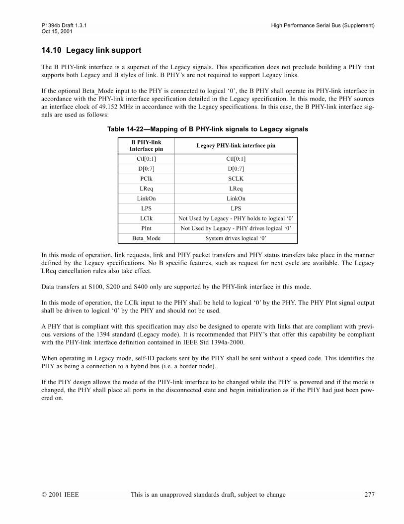
P1394b Draft 1.3.1 High Performance Serial Bus (Supplement)Oct 15, 2001
14.10 Legacy link support
The B PHY-link interface is a superset of the Legacy signals. This specification does not preclude building a PHY thatsupports both Legacy and B styles of link. B PHYs are not required to support Legacy links.
If the optional Beta_Mode input to the PHY is connected to logical 0, the B PHY shall operate its PHY-link interface inaccordance with the PHY-link interface specification detailed in the Legacy specification. In this mode, the PHY sourcesan interface clock of 49.152 MHz in accordance with the Legacy specifications. In this case, the B PHY-link interface sig-nals are used as follows:
In this mode of operation, link requests, link and PHY packet transfers and PHY status transfers take place in the mannerdefined by the Legacy specifications. No B specific features, such as request for next cycle are available. The LegacyLReq cancellation rules also take effect.
Data transfers at S100, S200 and S400 only are supported by the PHY-link interface in this mode.
In this mode of operation, the LClk input to the PHY shall be held to logical 0 by the PHY. The PHY PInt signal outputshall be driven to logical 0 by the PHY and should not be used.
A PHY that is compliant with this specification may also be designed to operate with links that are compliant with previ-ous versions of the 1394 standard (Legacy mode). It is recommended that PHYs that offer this capability be compliantwith the PHY-link interface definition contained in IEEE Std 1394a-2000.
When operating in Legacy mode, self-ID packets sent by the PHY shall be sent without a speed code. This identifies thePHY as being a connection to a hybrid bus (i.e. a border node).
If the PHY design allows the mode of the PHY-link interface to be changed while the PHY is powered and if the mode ischanged, the PHY shall place all ports in the disconnected state and begin initialization as if the PHY had just been pow-ered on.
Table 14-22Mapping of B PHY-link signals to Legacy signals
B PHY-link Interface pin Legacy PHY-link interface pin
Ctl[0:1] Ctl[0:1]
D[0:7] D[0:7]
PClk SCLK
LReq LReq
LinkOn LinkOn
LPS LPS
LClk Not Used by Legacy - PHY holds to logical 0
PInt Not Used by Legacy - PHY drives logical 0
Beta_Mode System drives logical 0
© 2001 IEEE This is an unapproved standards draft, subject to change 277
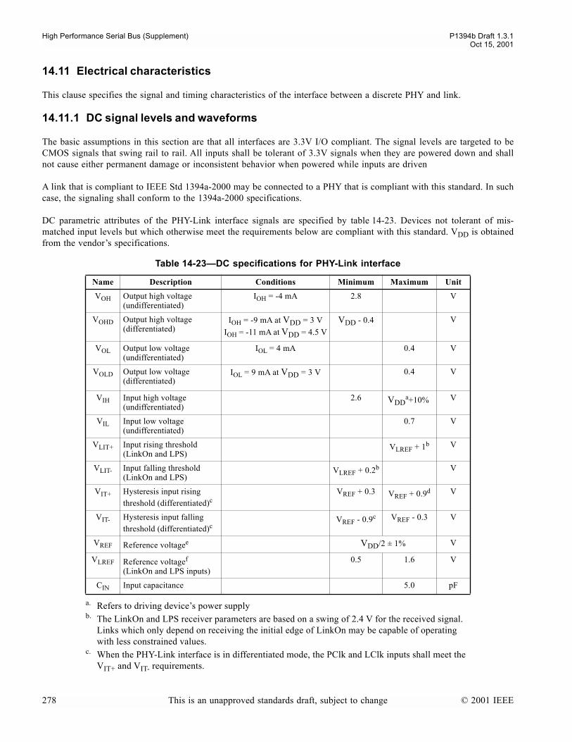
High Performance Serial Bus (Supplement) P1394b Draft 1.3.1Oct 15, 2001
14.11 Electrical characteristics
This clause specifies the signal and timing characteristics of the interface between a discrete PHY and link.
14.11.1 DC signal levels and waveforms
The basic assumptions in this section are that all interfaces are 3.3V I/O compliant. The signal levels are targeted to beCMOS signals that swing rail to rail. All inputs shall be tolerant of 3.3V signals when they are powered down and shallnot cause either permanent damage or inconsistent behavior when powered while inputs are driven
A link that is compliant to IEEE Std 1394a-2000 may be connected to a PHY that is compliant with this standard. In suchcase, the signaling shall conform to the 1394a-2000 specifications.
DC parametric attributes of the PHY-Link interface signals are specified by table 14-23. Devices not tolerant of mis-matched input levels but which otherwise meet the requirements below are compliant with this standard. VDD is obtainedfrom the vendors specifications.
Table 14-23DC specifications for PHY-Link interface
Name Description Conditions Minimum Maximum Unit
VOH Output high voltage(undifferentiated)
IOH = -4 mA 2.8 V
VOHD Output high voltage(differentiated)
IOH = -9 mA at VDD = 3 V
IOH = -11 mA at VDD = 4.5 V
VDD - 0.4 V
VOL Output low voltage(undifferentiated)
IOL = 4 mA 0.4 V
VOLD Output low voltage(differentiated)
IOL = 9 mA at VDD = 3 V 0.4 V
VIH Input high voltage(undifferentiated)
2.6 VDDa+10%
a. Refers to driving devices power supply
V
VIL Input low voltage(undifferentiated)
0.7 V
VLIT+ Input rising threshold(LinkOn and LPS)
VLREF + 1b
b. The LinkOn and LPS receiver parameters are based on a swing of 2.4 V for the received signal. Links which only depend on receiving the initial edge of LinkOn may be capable of operating with less constrained values.
V
VLIT- Input falling threshold(LinkOn and LPS)
VLREF + 0.2b V
VIT+ Hysteresis input rising threshold (differentiated)c
c. When the PHY-Link interface is in differentiated mode, the PClk and LClk inputs shall meet the VIT+ and VIT- requirements.
VREF + 0.3 VREF + 0.9d V
VIT- Hysteresis input falling threshold (differentiated)c
VREF - 0.9c VREF - 0.3 V
VREF Reference voltagee VDD/2 ± 1% V
VLREF Reference voltagef
(LinkOn and LPS inputs)0.5 1.6 V
CIN Input capacitance 5.0 pF
278 This is an unapproved standards draft, subject to change © 2001 IEEE

P1394b Draft 1.3.1 High Performance Serial Bus (Supplement)Oct 15, 2001
14.11.2 AC timing
The protocol of this interface is designed such that all inputs and outputs at this interface can be registered immediatelybefore or after the I/O pad and buffer. No state transitions need be made that depend directly on the chip inputs; chip out-puts can come directly from registers without combinational delay or additional loading. This configuration provides gen-erous margins on setup and hold time.
Timing follows normal source-clocked signal conventions. A 0.5 ns allowance is made for skew through an (optional) iso-lation barrier.
The rise and fall time measurement definitions, tR and tF, for PClk, LClk, Ctl[0:1], D[0:n], PInt, and LReq are shown infigure 14-16.
Other signal characteristics of the PHY-Link interface are specified by table 14-24. If an isolation barrier is implementedit shall cause neither delay nor skew in excess of the values specified. AC measurements shall be taken from the 1.575 Vlevel of PClk or LClk to the input or output Ctl[0:1], D[0:n] or LReq levels and shall assume an output load of 10 pF.
d. When designing a device capable of both undifferentiated and differentiated operation, VIH and VIL effectively constrain these VIT+ and VIT- values to VREF + 0.8 V and VREF - 0.8 V, respec-tively.
e. For some applications, a device can be compliant with these DC specifications even if a different VREF is chosen.
f. For a particular application, there is a single value for each devices nominal bias point, VLREF, which shall be within the range specified. VLREF should be chosen in conjunction with the receiver parameters so that a loss of power by the transmitting device is perceived as zero by the receiving device.
Figure 14-16Signal levels for rise and fall times
Table 14-24AC timing parameters
Name Description Minimum Maximum Unit
PClk or LClk frequency 98.304 ± 100 ppm MHz
DCP PClk duty cycle 35 65 %
DCL LClk duty cyclea DCP-5 DCP+5 %
jL LClk jitter (pk-pk)b jP+0.50 ns
tR Rise time -- 3.5 ns
tF Fall time -- 3.5 ns
tPLDelay from rising edge of PClk into the link to the rising edge of LClk from the link. 5 ns
tSK Skew through isolation barrier 0 0.5 ns
90%90%
10%10%
tR tF
© 2001 IEEE This is an unapproved standards draft, subject to change 279
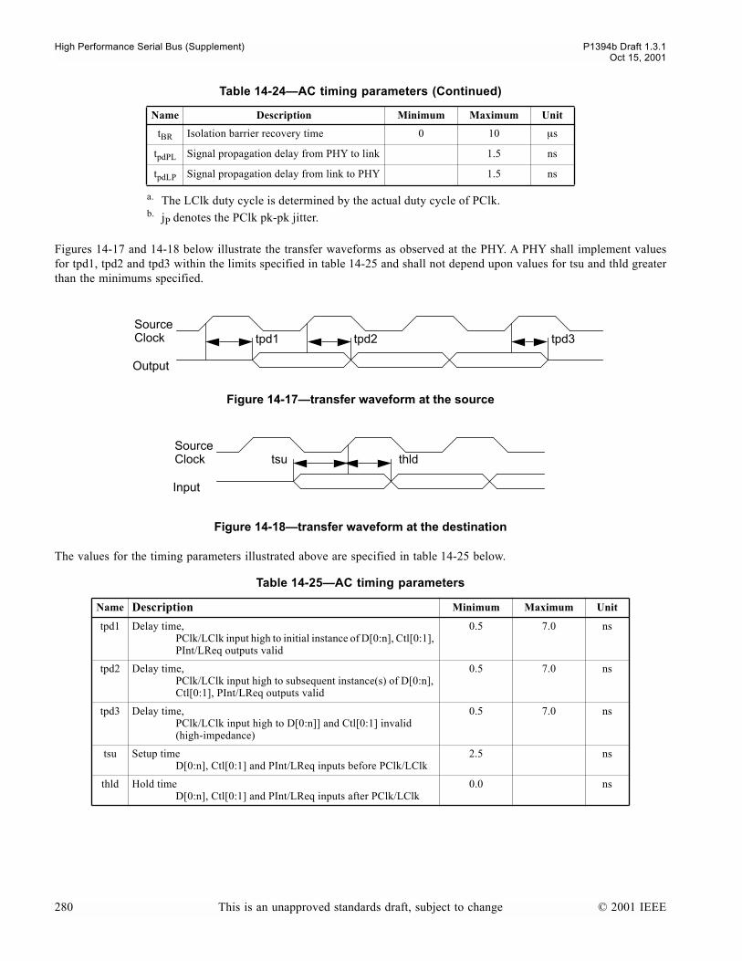
High Performance Serial Bus (Supplement) P1394b Draft 1.3.1Oct 15, 2001
Figures 14-17 and 14-18 below illustrate the transfer waveforms as observed at the PHY. A PHY shall implement valuesfor tpd1, tpd2 and tpd3 within the limits specified in table 14-25 and shall not depend upon values for tsu and thld greaterthan the minimums specified.
The values for the timing parameters illustrated above are specified in table 14-25 below.
tBR Isolation barrier recovery time 0 10 µs
tpdPL Signal propagation delay from PHY to link 1.5 ns
tpdLP Signal propagation delay from link to PHY 1.5 ns
a. The LClk duty cycle is determined by the actual duty cycle of PClk.b. jP denotes the PClk pk-pk jitter.
Figure 14-17transfer waveform at the source
Figure 14-18transfer waveform at the destination
Table 14-25AC timing parameters
Name Description Minimum Maximum Unit
tpd1 Delay time,PClk/LClk input high to initial instance of D[0:n], Ctl[0:1], PInt/LReq outputs valid
0.5 7.0 ns
tpd2 Delay time,PClk/LClk input high to subsequent instance(s) of D[0:n], Ctl[0:1], PInt/LReq outputs valid
0.5 7.0 ns
tpd3 Delay time,PClk/LClk input high to D[0:n]] and Ctl[0:1] invalid (high-impedance)
0.5 7.0 ns
tsu Setup timeD[0:n], Ctl[0:1] and PInt/LReq inputs before PClk/LClk
2.5 ns
thld Hold timeD[0:n], Ctl[0:1] and PInt/LReq inputs after PClk/LClk
0.0 ns
Table 14-24AC timing parameters (Continued)
Name Description Minimum Maximum Unit
Sourcetpd1 tpd2 tpd3
LR
Clock
Output
Sourcetsu thld
Input
Clock
280 This is an unapproved standards draft, subject to change © 2001 IEEE
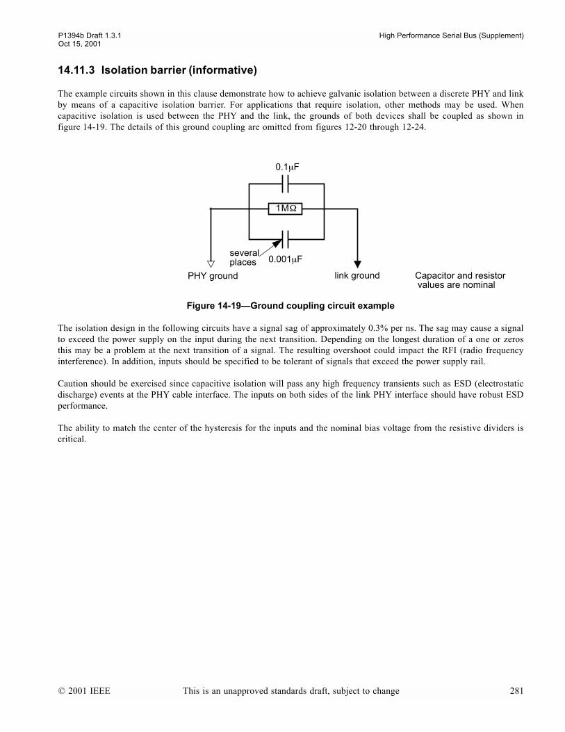
P1394b Draft 1.3.1 High Performance Serial Bus (Supplement)Oct 15, 2001
14.11.3 Isolation barrier (informative)
The example circuits shown in this clause demonstrate how to achieve galvanic isolation between a discrete PHY and linkby means of a capacitive isolation barrier. For applications that require isolation, other methods may be used. Whencapacitive isolation is used between the PHY and the link, the grounds of both devices shall be coupled as shown infigure 14-19. The details of this ground coupling are omitted from figures 12-20 through 12-24.
The isolation design in the following circuits have a signal sag of approximately 0.3% per ns. The sag may cause a signalto exceed the power supply on the input during the next transition. Depending on the longest duration of a one or zerosthis may be a problem at the next transition of a signal. The resulting overshoot could impact the RFI (radio frequencyinterference). In addition, inputs should be specified to be tolerant of signals that exceed the power supply rail.
Caution should be exercised since capacitive isolation will pass any high frequency transients such as ESD (electrostaticdischarge) events at the PHY cable interface. The inputs on both sides of the link PHY interface should have robust ESDperformance.
The ability to match the center of the hysteresis for the inputs and the nominal bias voltage from the resistive dividers iscritical.
Figure 14-19Ground coupling circuit example
PHY ground link ground
1M
Ω
0.001
µ
F
0.1
µ
F
severalplaces
Capacitor and resistor values are nominal
© 2001 IEEE This is an unapproved standards draft, subject to change 281

High Performance Serial Bus (Supplement) P1394b Draft 1.3.1Oct 15, 2001
The example circuits that follow illustrate different requirements of the various signals of the PHY-link interface.
Figure 14-20Capacitive isolation barrier circuit example for Ctl[0:1] and D[0:n]
Figure 14-21Capacitive isolation barrier circuit example for LinkOn
Device A Device B
power
5K
Ω
5K
Ω
5K
Ω
5K
Ω
3
00
Ω to Device A or
Device B ground
power
0.001
µ
F 0.001
µ
F
0.01µFPHY link
100Ω
5KΩ
1.6
KΩ
power
Optional current limiting resistor
282 This is an unapproved standards draft, subject to change © 2001 IEEE
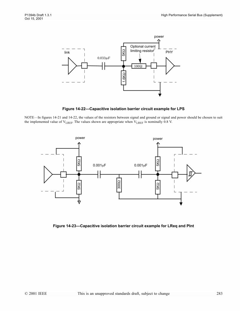
P1394b Draft 1.3.1 High Performance Serial Bus (Supplement)Oct 15, 2001
NOTEIn figures 14-21 and 14-22, the values of the resistors between signal and ground or signal and power should be chosen to suitthe implemented value of V
LREF
. The values shown are appropriate when V
LREF
is nominally 0.8 V.
Figure 14-22Capacitive isolation barrier circuit example for LPS
Figure 14-23Capacitive isolation barrier circuit example for LReq and PInt
0.033µF
link PHY
100Ω
5KΩ
1.6
KΩ
power
Optional current limiting resistor
power
5KΩ
5KΩ
5KΩ
5KΩ
300Ω
power
0.001µF 0.001µF
© 2001 IEEE This is an unapproved standards draft, subject to change 283
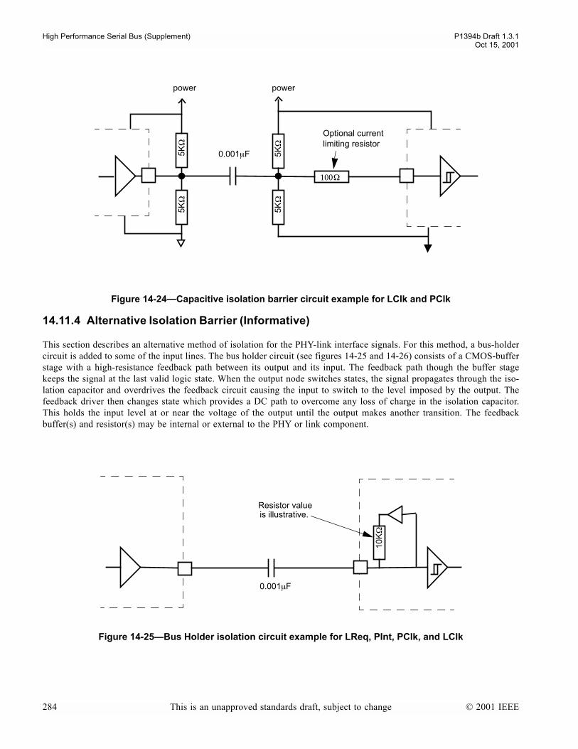
High Performance Serial Bus (Supplement) P1394b Draft 1.3.1Oct 15, 2001
14.11.4 Alternative Isolation Barrier (Informative)
This section describes an alternative method of isolation for the PHY-link interface signals. For this method, a bus-holdercircuit is added to some of the input lines. The bus holder circuit (see figures 14-25 and 14-26) consists of a CMOS-bufferstage with a high-resistance feedback path between its output and its input. The feedback path though the buffer stagekeeps the signal at the last valid logic state. When the output node switches states, the signal propagates through the iso-lation capacitor and overdrives the feedback circuit causing the input to switch to the level imposed by the output. Thefeedback driver then changes state which provides a DC path to overcome any loss of charge in the isolation capacitor.This holds the input level at or near the voltage of the output until the output makes another transition. The feedbackbuffer(s) and resistor(s) may be internal or external to the PHY or link component.
Figure 14-24Capacitive isolation barrier circuit example for LClk and PClk
Figure 14-25Bus Holder isolation circuit example for LReq, PInt, PClk, and LClk
Optional current
power
5K
Ω
5K
Ω
100
Ω
0.001
µ
F
power
5K
Ω
5K
Ω
limiting resistor
0.001µF
10K
Ω
Resistor valueis illustrative.
284 This is an unapproved standards draft, subject to change © 2001 IEEE

P1394b Draft 1.3.1 High Performance Serial Bus (Supplement)Oct 15, 2001
When bus holders are present on both the PHY and the link, the isolation circuit consists of a single capacitor in eachline. Bus holders may be used on CTL[0:1], D[0:7], LReq, PInt, PClk, LClk, PHY-link interface signals. For bi-direc-tional signals (D[0:7] and Ctl[0:1] bus holders are present on both the PHY and the link.
The threshold levels on LinkOn and LPS makes it more difficult to insure that a clocked signal will eventually cause theinput to switch to the correct state if a bus holder is driving the line, however weakly, to the wrong state. For these rea-sons, the standard isolation circuits for LinkOn and LPS (as shown in figures 14-21 and 14-22 respectively) are recom-mended.
If bus holders are present on both the PHY and the link and LPS is only implemented as a pulsed signal (preferred), thenthe Direct pin, if present, on the link may be tied either high or low as required by the link vendor. If LPS is not pulsedwhen Direct is tied high on the link, then the direct pin on the link shall be tied low when bus holders are used. If busholders are present on both the PHY and link, then the Direct pin on the PHY, if present, may be tied either high or lowas required by the vendor.
The presence of bus holders within a device may change the observed output voltage levels such that they may appear notto be operating in differentiated mode even though the Direct pin is tied low.
External bus holders may be added on to a PHY or link that does not have the bus holders integrated. When external busholders are present, the Direct pins on the PHY and link are set according to vendor instructions.
Figure 14-26Bus Holder isolation circuit example for Ctl[0:1] and D[0:n]
Device A Device B
0.001
µ
F
10K
Ω
10K
Ω
Capacitor and resistor valuesare illustrative.
© 2001 IEEE This is an unapproved standards draft, subject to change 285

High Performance Serial Bus (Supplement) P1394b Draft 1.3.1Oct 15, 2001
286 This is an unapproved standards draft, subject to change © 2001 IEEE

P1394b Draft 1.3.1 High Performance Serial Bus (Supplement)Oct 15, 2001
15. PIL-FOP Serial Interface
This section describes an interface between a link and a discrete PHY that may be used for all Serial Bus speeds (S100,S200, S400, S800, and S1600). This interface provides a less costly means of isolation than does the PHY-link interface.Additionally, this interface allows the two components using this interface to be physically separated either across aplanar or in different enclosures.
For this interface, a PHY with a single Beta port is integrated into a link. This combination is referred to as the PIL. ThePIL is then connected to a Beta capable port on a fan-out PHY (the FOP). The connection between the PIL and the FOPmay optionally include series blocking capacitors to provide galvanic isolation. The PIL and the FOP may be in differentpower domains.
NOTESince the PIL-FOP interface is a beta copper connection, the required speed is S400
β
and the maximum allowed speed isS3200
β
as specified in table 11-1
15.1 Operating Model
The operating model is that the PIL effectively serves the role of a traditional link, while the FOP operates as the effectivePHY in the system. In this arrangement, the combination of PIL and FOP operates as a single node on the network. A spe-cial packet protocol is used on the serial PIL-FOP interface to allow read and write access to the PHY registers in theFOP and for the FOP to signal various events to the PIL. This ensures that a PIL and FOP are indistinguishable from aPHY and link to system software.
A PHY that is designed to be used as a FOP may also be designed to allow the PIL port to be used as a standard, Beta-only or bilingual port. For such a PHY, the highest number port shall be the one that is used as the PIL port. When theport is attached to a PIL, the self-ID packet for the FOP will indicate that the PIL port is not implemented and any PHYpacket access to the registers associated with the PIL port on the FOP will indicate that the port is not implemented. Forexample, if a PHY has 6 ports, the PIL may only be attached to port number 5 (the 6th port) and if a PIL is attached, thenin its self-ID packets, the FOP will only report that 5 ports are present.
Figure 15-1 Possible System Configuration using a fan-out PHY Device
Beta Serial BusConnection B
FAN-OUTPHY
LinkOn
1394-ENABLED DEVICE e.g., PC, Set top box, etc.
Internal or External
INTEGRATED PHY and LINK
BetaLINK
BetaB-ONLY
PHY 4
4
4
4
Serial BusConnections
© 2001 IEEE This is an unapproved standards draft, subject to change 287

High Performance Serial Bus (Supplement) P1394b Draft 1.3.1Oct 15, 2001
As with the link connection on a PHY, the PIL connection on the FOP is not considered to be an active port on the FOPwhen determining if a port on the FOP can be placed into standby. If the FOP receives a standby PHY command, then theFOP will honor the request if the addressed port is the only active port on the FOP other than the PIL port.
The FOP shall provide a LinkOn signal. This signal has identical electrical characteristics and logical behavior as theLinkOn signal of the PHY-link interface defined in clause 14.
15.2 PIL-FOP Connection Management
The PIL-FOP interface behavior is similar to that of a connection between any other two Beta ports. The connection man-agement state machine for the PIL and FOP are simplified versions of the standard Beta port connection managementstate machine.
The PIL uses the following states from the port connection manager state machine in clause 11.5: P0:Disconnected,P2:Active; P7:Standby Initiator; P9:Standby; P10:Restoring. The FOP uses these states from that state machine: P0:Dis-connected, P2:Active; P8:Standby Target; P9:Standby; P10:Restoring. Both PIL and FOP transition from P0:Disconnectedto P9:Standby when connected (normally the P0:P11 transition). Variables and functions needed for the other states arenot required for this interface. The configuration requests that are used to support transitions to unimplemented states arenot allowed on the PIL-FOP interface.
15.2.1 Power on
When the PIL or FOP powers on, it begins toning. When both detect toning, they exchange speed codes. When they com-pete the exchange of speed codes, they transition to the Standby state.
The negotiated speed between the PIL and the FOP and the speed reported in the link_spd field of the Bus_Info_Blockshall be consistent.
15.2.2 PIL-FOP Negotiation
The PIL-FOP negotiation protocol allows a PHY that is PIL capable to be used with a PHY that is FOP capable and havethem establish the proper relationship without requiring strapping or other means of setting the mode. It is possible to usethe PIL-FOP negotiation protocol to have two connected devices, in separate enclosures establish a PIL-FOP relationship.
When the PIL and FOP begin exchange of speed codes, a PIL capable PHY will set the PIL_capable field in the speednegotiation code. A FOP will set the FOP_capable field in its speed negotiation code. When a PIL-capable PHY receivesa speed code with the FOP_capable field set, it will select a compatible speed and send the speed code with thePIL_capable field set and with the ACK field set. Otherwise, it will clear the PIL_capable field when it sends theacknowledgement. A FOP_capable PHY, will send its speed code with the FOP_capable field set. If it receives a speedcode with the PIL_capable field set, it set the FOP_capable field when it acknowledges the speed. Otherwise, it will clearthe field.
A PIL may be designed such that it may only be used with a FOP. A PIL may also be designed such that it can be usedas a single port PHY. When a PIL capable PHY is used in a system with a FOP, the PIL implementation may rely onvendor dependent means to cause the PHY to behave as a PIL, or the PHY may use the PIL-FOP negotiation protocol inorder to select the correct mode of operation. A PIL that is only designed to operate as a PIL may support the PIL-FOPnegotiation protocol.
A FOP may be designed such that a port may only be connected to a PIL. A FOP may also be designed such that the high-est numbered port may be connected to a PIL or operate as a normal PHY port. For such a dual-role PHY, a vendor spe-cific means may be used to cause the PHY to act as a FOP, or the PHY may use the PIL-FOP negotiation protocol toselect the correct mode of operation. A FOP that is designed such that one port shall be connected to a PIL may supportthe PIL-FOP negotiation protocol on that port.
288 This is an unapproved standards draft, subject to change © 2001 IEEE
P1394b Draft 1.3.1 High Performance Serial Bus (Supplement)Oct 15, 2001
The system implementer is responsible to insure that the PIL and FOP components are compatible. If the intent is to usethe PIL-FOP negotiation protocol, then both devices shall support the protocol.
A device that is only capable of operating as a PIL and not also as a single-port PHY shall not be connected to a useraccessible connector.
15.2.3 PIL-FOP Restore
Either the PIL or FOP may initiate an exit from Standby by sending a training sequence. When training is complete, theFOP will arbitrate for and win control of the Serial Bus and then send a Restore PHY packet to the PIL. This packet con-tains the PHY-ID for the PIL and FOP, the current setting of the R(root) bit, the current gap count, the gap count stickybit and an indication if there was a bus reset since the interface was in standby.
If no port is in the Active or Standby state when the FOP sends the Restore packet, then the R bit will be set to one, T(gap count reset disable) bit will be set to 0, the PHY-ID will be set to 0, the gap count will be set to 63, the A (asynchro-nous phase) bit will be set to zero, and the N (reset notify bit) will be set to 1.
If a port on the FOP is in the Standby state when the Restore packet is sent, the FOP shall use the previously receivedvalues for PHY ID, T, A, N and gap count. If the FOP is root, then the R bit of the Restore packet will be set to one.
15.2.4 Port Restore
A port on a FOP may be restored due to action of the PIL or of the Uncle. If the PIL-FOP interface is active, the PIL mayinitiate the Restore by sending anything other than a NONE_* asynchronous request or isochronous request. When theFOP receives the request, it will respond by sending a Restore_Notify point-to-point packet to the PIL and will start therestore process on the port in Standby. When the PIL receives the Restore_Notify, it should withdraw the request (startsending NONE requests) until the FOP sends a Restore packet or until the FOP sends a Serial Bus reset. When the FOPcompetes the Restore operation, it will receive a Restore packet from the Uncle that will be forwarded to the PIL.
The Uncle may initiate the restore operation to the FOP with the PIL-FOP interface Active, in Standby. or off. If the inter-face is in Standby or off, then no indication is sent to the PIL unless the Int_Enable bit in the FOP is set to one. IfInt_Enable is set the FOP will assert LinkOn. Additionally, if the interface is in Standby, the FOP will send a trainingsequence. If the PIL-FOP interface is Active when the resume sequence starts, the FOP will send a Restore_Notify point-to-point packet. When the Uncle sends the Restore PHY packet to complete the restore sequence, the PIL-FOP interfacemay or may not be active at that time. If it is Active, then the Restore PHY packet is repeated to the PIL. Otherwise, theinitialization of the PIL-FOP interface completes as described in clause 15.2.3.
15.2.5 Loss of Synchronization
If either the PIL or FOP loses synchronization, they do not return to the disconnected state and no bus reset is generated.Instead, they transition to the Restoring state and retrain. When either the PIL or FOP detects the training sequence, it willtransition to the Restoring state.
15.2.6 Loss of Power
When either the PIL or FOP loses power or experiences any other condition that causes it to lose state, the device shallplace its port in the Disconnected state and not tone for at lease 12 toning intervals. This period of time with no bus activ-ity insures that the other device has placed itself in the Disconnected state.
15.2.7 LPS
The logical equivalent of LPS active from the PIL to the FOP is when the PIL-FOP interface is not in the Disconnectedor Standby states. When LPS, or its logical equivalent in the PIL, goes inactive, the PIL will become a Standby Initiatorand send a STANDBY configuration request to the FOP. The PIL and FOP will then transition to the Standby state.
© 2001 IEEE This is an unapproved standards draft, subject to change 289
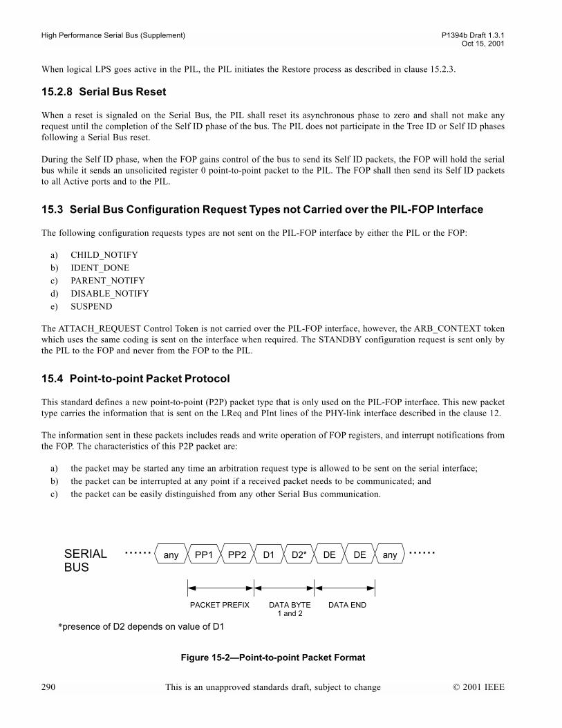
High Performance Serial Bus (Supplement) P1394b Draft 1.3.1Oct 15, 2001
When logical LPS goes active in the PIL, the PIL initiates the Restore process as described in clause 15.2.3.
15.2.8 Serial Bus Reset
When a reset is signaled on the Serial Bus, the PIL shall reset its asynchronous phase to zero and shall not make anyrequest until the completion of the Self ID phase of the bus. The PIL does not participate in the Tree ID or Self ID phasesfollowing a Serial Bus reset.
During the Self ID phase, when the FOP gains control of the bus to send its Self ID packets, the FOP will hold the serialbus while it sends an unsolicited register 0 point-to-point packet to the PIL. The FOP shall then send its Self ID packetsto all Active ports and to the PIL.
15.3 Serial Bus Configuration Request Types not Carried over the PIL-FOP Interface
The following configuration requests types are not sent on the PIL-FOP interface by either the PIL or the FOP:
a) CHILD_NOTIFYb) IDENT_DONEc) PARENT_NOTIFYd) DISABLE_NOTIFYe) SUSPEND
The ATTACH_REQUEST Control Token is not carried over the PIL-FOP interface, however, the ARB_CONTEXT tokenwhich uses the same coding is sent on the interface when required. The STANDBY configuration request is sent only bythe PIL to the FOP and never from the FOP to the PIL.
15.4 Point-to-point Packet Protocol
This standard defines a new point-to-point (P2P) packet type that is only used on the PIL-FOP interface. This new packettype carries the information that is sent on the LReq and PInt lines of the PHY-link interface described in the clause 12.
The information sent in these packets includes reads and write operation of FOP registers, and interrupt notifications fromthe FOP. The characteristics of this P2P packet are:
a) the packet may be started any time an arbitration request type is allowed to be sent on the serial interface;b) the packet can be interrupted at any point if a received packet needs to be communicated; andc) the packet can be easily distinguished from any other Serial Bus communication.
Figure 15-2Point-to-point Packet Format
SERIAL PP1 D1 D2*
PACKET PREFIX DATA BYTE
......
DATA END
BUSany PP2 DE DE any......
1 and 2
*presence of D2 depends on value of D1
290 This is an unapproved standards draft, subject to change © 2001 IEEE
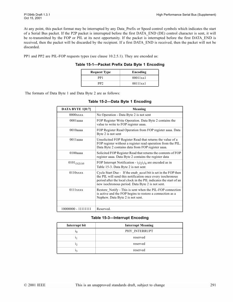
P1394b Draft 1.3.1 High Performance Serial Bus (Supplement)Oct 15, 2001
At any point, this packet format may be interrupted by any Data_Prefix or Speed control symbols which indicates the startof a Serial Bus packet. If the P2P packet is interrupted before the first DATA_END (DE) control character is sent, it willbe re-transmitted by the FOP or PIL at its next opportunity. If the packet is interrupted before the first DATA_END isreceived, then the packet will be discarded by the recipient. If a first DATA_END is received, then the packet will not bediscarded.
PP1 and PP2 are PIL-FOP requests types (see clause 10.2.5.1). They are encoded as:
The formats of Data Byte 1 and Data Byte 2 are as follows:
Table 15-1Packet Prefix Data Byte 1 Encoding
Request Type Encoding
PP1 00011xx1
PP2 00111xx1
Table 15-2Data Byte 1 Encoding
DATA BYTE 1[0:7] Meaning
0000xxxx No Operation - Data Byte 2 is not sent
0001aaaa FOP Register Write Operation. Data Byte 2 contains the value to write to FOP register aaaa.
0010aaaa FOP Register Read Operation from FOP register aaaa. Data Byte 2 is not sent
0011aaaa Unsolicited FOP Register Read that returns the value of a FOP register without a register read operation from the PIL. Data Byte 2 contains data from FOP register aaaa.
0100aaaa Solicited FOP Register Read that returns the contents of FOP register aaaa. Data Byte 2 contains the register data
0101i3i2i1i0 FOP Interrupt Notification - i3i2i1i0 are encoded as in Table 15-3. Data Byte 2 is not sent
0110xxxx Cycle Start Due - If the enab_accel bit is set in the FOP then the PIL will send this notification once every isochronous period after the local clock in the PIL indicates the start of an new isochronous period. Data Byte 2 is not sent.
0111xxxx Restore_Notify - This is sent when the PIL-FOP connection is active and the FOP begins to restore a connection as a Nephew. Data Byte 2 is not sent.
10000000 - 11111111 Reserved.
Table 15-3Interrupt Encoding
Interrupt bit Interrupt Meaning
i0 PHY_INTERRUPT
i1 reserved
i2 reserved
i3 reserved
© 2001 IEEE This is an unapproved standards draft, subject to change 291

High Performance Serial Bus (Supplement) P1394b Draft 1.3.1Oct 15, 2001
292 This is an unapproved standards draft, subject to change © 2001 IEEE
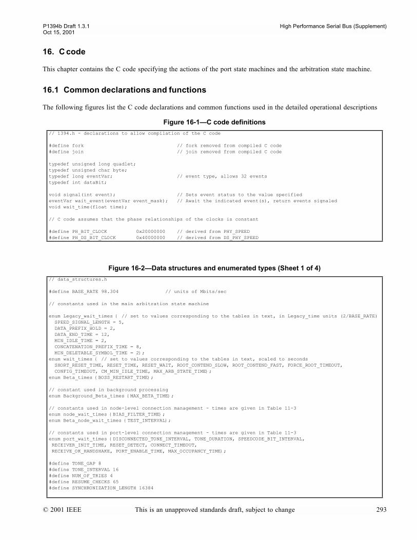
P1394b Draft 1.3.1 High Performance Serial Bus (Supplement)Oct 15, 2001
16. C code
This chapter contains the C code specifying the actions of the port state machines and the arbitration state machine.
16.1 Common declarations and functions
The following figures list the C code declarations and common functions used in the detailed operational descriptions
Figure 16-1C code definitions
// 1394.h - declarations to allow compilation of the C code
#define fork // fork removed from compiled C code#define join // join removed from compiled C code
typedef unsigned long quadlet;typedef unsigned char byte;typedef long eventVar; // event type, allows 32 eventstypedef int dataBit;
void signal(int event); // Sets event status to the value specifiedeventVar wait_event(eventVar event_mask); // Await the indicated event(s), return events signaledvoid wait_time(float time);
// C code assumes that the phase relationships of the clocks is constant
#define PH_BIT_CLOCK 0x20000000 // derived from PHY_SPEED#define PH_DS_BIT_CLOCK 0x40000000 // derived from DS_PHY_SPEED
Figure 16-2Data structures and enumerated types (Sheet 1 of 4)
// data_structures.h
#define BASE_RATE 98.304 // units of Mbits/sec
// constants used in the main arbitration state machine
enum Legacy_wait_times // set to values corresponding to the tables in text, in Legacy_time units (2/BASE_RATE) SPEED_SIGNAL_LENGTH = 5, DATA_PREFIX_HOLD = 2, DATA_END_TIME = 12, MIN_IDLE_TIME = 2, CONCATENATION_PREFIX_TIME = 8, MIN_DELETABLE_SYMBOL_TIME = 2; enum wait_times // set to values corresponding to the tables in text, scaled to seconds SHORT_RESET_TIME, RESET_TIME, RESET_WAIT, ROOT_CONTEND_SLOW, ROOT_CONTEND_FAST, FORCE_ROOT_TIMEOUT, CONFIG_TIMEOUT, CM_MIN_IDLE_TIME, MAX_ARB_STATE_TIME; enum Beta_times BOSS_RESTART_TIME;
// constant used in background processingenum Background_Beta_times MAX_BETA_TIME;
// constants used in node-level connection management - times are given in Table 11-3enum node_wait_times BIAS_FILTER_TIME;enum Beta_node_wait_times TEST_INTERVAL;
// constants used in port-level connection management - times are given in Table 11-3enum port_wait_times DISCONNECTED_TONE_INTERVAL, TONE_DURATION, SPEEDCODE_BIT_INTERVAL, RECEIVER_INIT_TIME, RESET_DETECT, CONNECT_TIMEOUT, RECEIVE_OK_HANDSHAKE, PORT_ENABLE_TIME, MAX_OCCUPANCY_TIME;
#define TONE_GAP 8#define TONE_INTERVAL 16#define NUM_OF_TRIES 4#define RESUME_CHECKS 65#define SYNCHRONIZATION_LENGTH 16384
© 2001 IEEE This is an unapproved standards draft, subject to change 293

High Performance Serial Bus (Supplement) P1394b Draft 1.3.1Oct 15, 2001
// data structures
typedef enum S100 = 0, S200 = 1, S400 = 2, S800 = 3, S1600 = 4, S3200 = 5, NO_SPEED = 6, DEFAULT = 7 speedCode;typedef enum // Types of bus requests made by link across PHY/link interface // the boolean immediate_request replaces use of IMMED_REQ NO_REQ, ISOCH_REQ, PRIORITY_REQ, FAIR_REQ breq_type;
typedef enum // Tracks the PHY state (names per state diagrams) R0, R1, T0, T1, T2, T3, S0, S1, S2, S3, S4, A0, A1, A2, RX, TX, PH PHY_state_type;typedef enum P0, P1, P2, P3, P4, P5, P6, P7, P8, P9, P10, P11, P12 port_state_type;typedef enum L, H tpSig; // Differential signal on twisted pairtypedef enum GND, Bias_On, ZZ tpBiasSig;typedef struct tpSig TpA; tpSig TpB; portData; // Port data structuretypedef enum RX_IDLE = 0, RX_PARENT_NOTIFY = 1, RX_REQUEST_CANCEL = 1, RX_IDENT_DONE = 2, RX_SELF_ID_GRANT = 3, RX_REQUEST = 3, RX_ROOT_CONTENTION = 4, RX_GRANT = 4, RX_SUSPEND = 4, RX_PARENT_HANDSHAKE = 5, RX_DATA_END = 5, RX_CHILD_HANDSHAKE = 6, RX_DISABLE_NOTIFY = 6, RX_DATA_PREFIX = 7, RX_BUS_RESET = 8 RX_arbstate;typedef enum TX_IDLE = 0, TX_REQUEST = 1, TX_GRANT = 1, TX_DISABLE_NOTIFY = 2, TX_PARENT_NOTIFY = 3, TX_SUSPEND = 4, TX_DATA_PREFIX = 5, TX_CHILD_NOTIFY = 6, TX_IDENT_DONE = 6, TX_DATA_END = 7, TX_BUS_RESET = 8 TX_arbstate; typedef struct RX_arbstate RX_arb; portData data; RX_signal;
typedef enum LTP_TEST = 0, ATTACH_IN_PROGRESS = 1 LTP_mode_type;#define COLLISION_LIMIT 7
typedef enum B_Link, Legacy_Link linkType;typedef enum grant_senior, grant_link, grant_null, grant_junior, boss_management_actions boss_eop_status;
// CTRL, CONFIG_REQUEST and INVALID are used internally within the port machines// DATA, ARB_STATE and LEGACY_ARB are used for communicating to the arb state machine// DS_RAW_ARB is used to pass the overloaded received Legacy arb states to the process_request block// for filtering based on the current PHY statetypedef enum DATA, CTRL, ARB_REQUEST, CONFIG_REQUEST, INVALID, ARB_STATE, DS_RAW_ARB, LEGACY_ARB portTag;
typedef enum LEGACY, BETA, UNSPECIFIED pktType;
typedef enum // first the arb-states corresponding to CTRL symbols // SPEEDa, SPEEDb and SPEEDc are used only internally in the port CYCLE_START_EVEN = 1, CYCLE_START_ODD = 2, ATTACH_REQUEST = 3, ARB_CONTEXT = 3, SPEEDa = 4, DATA_END = 5, DATA_NULL = 6, SPEEDb = 7, // note GRANT and SELF_ID_GRANT are the same code GRANT = 8, SELF_ID_GRANT = 8, DATA_PREFIX = 9, GRANT_ISOCH = 10, SPEEDc = 11, ASYNC_EVEN = 12, ASYNC_ODD = 13, BUS_RESET = 14, IDLE = 15, SPEED = 16, SPEED_RAW = 17, // then the arb-states corresponding to CONFIG_REQUEST symbols // note, CHILD_NOTIFY, PARENT_HANDSHAKE and IDENT_DONE are the same code // note TRAINING is the lowest value of these enum types TRAINING = 18, STANDBY = 19, CHILD_NOTIFY = 20, IDENT_DONE = 20, PARENT_HANDSHAKE = 20, // note PARENT_NOTIFY and ROOT_CONTENTION are the same code PARENT_NOTIFY = 21, ROOT_CONTENTION = 21, DISABLE_NOTIFY = 22, SUSPEND = 23, OPERATION = 24, CHILD_HANDSHAKE = 25, REQUEST_CANCEL = 26, LEGACY_REQUEST = 27, LEGACY_PHASE = 28, // DATA_BYTE is only used in the arb state machine DATA_BYTE = 29 ArbState;
// encode the two types of priority as two nibbles, high order for odd phasetypedef enum A_NONE = 0, NONE_ODD = 0x13, NEXT_EVEN = 0x25, NONE_EVEN = 0x31, CURRENT = 0x44, NEXT_ODD = 0x52, CYCLE_START_REQ = 0x66, BORDER = 0x77 asyncReqType;
typedef enum I_NONE = 0, ISOCH_NONE = 0x11, ISOCH_ODD = 0x42, ISOCH_EVEN = 0x24, ISOCH_IN_PHASE = 0x33, ISOCH_CURRENT = 0x55 isochReqType; // Note, ISOCH_IN_PHASE is defined for simple comparisons to determine // if a particular request is for the current phase. Is does not appear // on the serial bus
Figure 16-2Data structures and enumerated types (Sheet 2 of 4)
294 This is an unapproved standards draft, subject to change © 2001 IEEE
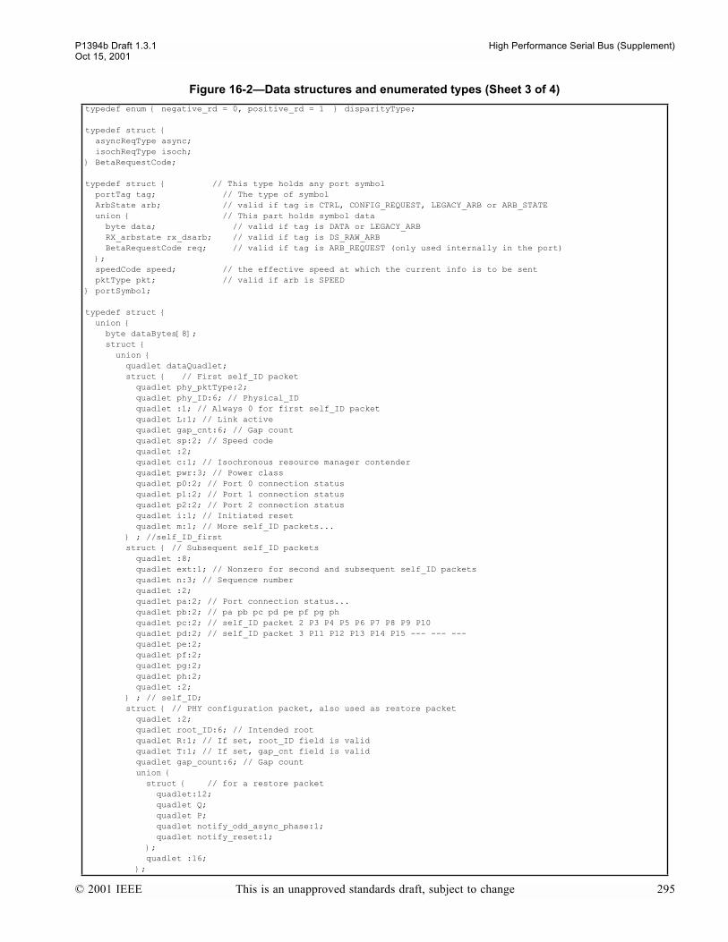
P1394b Draft 1.3.1 High Performance Serial Bus (Supplement)Oct 15, 2001
typedef enum negative_rd = 0, positive_rd = 1 disparityType;
typedef struct asyncReqType async; isochReqType isoch; BetaRequestCode;
typedef struct // This type holds any port symbol portTag tag; // The type of symbol ArbState arb; // valid if tag is CTRL, CONFIG_REQUEST, LEGACY_ARB or ARB_STATE union // This part holds symbol data byte data; // valid if tag is DATA or LEGACY_ARB RX_arbstate rx_dsarb; // valid if tag is DS_RAW_ARB BetaRequestCode req; // valid if tag is ARB_REQUEST (only used internally in the port) ; speedCode speed; // the effective speed at which the current info is to be sent pktType pkt; // valid if arb is SPEED portSymbol;
typedef struct union byte dataBytes[8]; struct union quadlet dataQuadlet; struct // First self_ID packet quadlet phy_pktType:2; quadlet phy_ID:6; // Physical_ID quadlet :1; // Always 0 for first self_ID packet quadlet L:1; // Link active quadlet gap_cnt:6; // Gap count quadlet sp:2; // Speed code quadlet :2; quadlet c:1; // Isochronous resource manager contender quadlet pwr:3; // Power class quadlet p0:2; // Port 0 connection status quadlet p1:2; // Port 1 connection status quadlet p2:2; // Port 2 connection status quadlet i:1; // Initiated reset quadlet m:1; // More self_ID packets... ; //self_ID_first struct // Subsequent self_ID packets quadlet :8; quadlet ext:1; // Nonzero for second and subsequent self_ID packets quadlet n:3; // Sequence number quadlet :2; quadlet pa:2; // Port connection status... quadlet pb:2; // pa pb pc pd pe pf pg ph quadlet pc:2; // self_ID packet 2 P3 P4 P5 P6 P7 P8 P9 P10 quadlet pd:2; // self_ID packet 3 P11 P12 P13 P14 P15 --- --- --- quadlet pe:2; quadlet pf:2; quadlet pg:2; quadlet ph:2; quadlet :2; ; // self_ID; struct // PHY configuration packet, also used as restore packet quadlet :2; quadlet root_ID:6; // Intended root quadlet R:1; // If set, root_ID field is valid quadlet T:1; // If set, gap_cnt field is valid quadlet gap_count:6; // Gap count union struct // for a restore packet quadlet:12; quadlet Q; quadlet P; quadlet notify_odd_async_phase:1; quadlet notify_reset:1; ; quadlet :16; ;
Figure 16-2Data structures and enumerated types (Sheet 3 of 4)
© 2001 IEEE This is an unapproved standards draft, subject to change 295

High Performance Serial Bus (Supplement) P1394b Draft 1.3.1Oct 15, 2001
; // phy_config; struct // Extended PHY packets (ping and other remote packets) quadlet :2; quadlet :6; // Physical_ID quadlet :2; // Always 0, identifies Exended PHY packet quadlet ext_type:4; // Extended type union struct union quadlet page:3; // Page_select quadlet e_cmnd:3; // Extended command ; quadlet port_num:4; // Port_select union struct quadlet reg:3; // Register address (add 0b1000 if paged register) quadlet data:8; // Register data (remote reply) ; struct // Remote confirmation quadlet :2; quadlet standby_fault:1; // Copies of equivalent PHY register bits... quadlet fault:1; quadlet connected:1; quadlet bias:1; quadlet disabled:1; quadlet ok:1; // Confirm command accepted or not quadlet cmnd:3; // Remote command ; // remote_cnfrm; ; ; struct // fields for Loop Test Packet quadlet :10; quadlet mode:1; // LTP mode quadlet G:1; // Generation number quadlet test_value:6; // Loop Test Packet comparison value ; ; ; // ext_phy; ; quadlet checkQuadlet; ; ; PHY_PKT;
// implementation dependent constants#define CONTENDER 1 // IMPLEMENTATION DEPENDENT#define POWER_CLASS 0b000 // IMPLEMENTATION DEPENDENT
#define NPORT 4 // number of ports - IMPLEMENTATION DEPENDENT
#define PHY_SPEED S800 // PHY speed - IMPLEMENTATION DEPENDENT#define DS_PHY_SPEED S400 // PHY speed for DS ports - IMPLEMENTATION DEPENDENT
const speedCode DS_port_speed[NPORT]; // Speed of each DS capable port - IMPLEMENTATION DEPENDENT
Figure 16-3PHY Services (Sheet 1 of 3)
// phy_services.h
// PMD services which apply on a per-port basis, the port is implicit// as these are referenced from the per-port code (except for bias_detect)
typedef enum PMD_CROSSOVER, PMD_NO_CROSSOVER, PMD_TONE_ON, // instructs the PMD to generate a tone (see 6.8.1) PMD_TONE_OFF, // instructs the PMD to cease generating a tone, // remove the signalling bias voltage and set the // port transmitters to high impedance
Figure 16-2Data structures and enumerated types (Sheet 4 of 4)
296 This is an unapproved standards draft, subject to change © 2001 IEEE
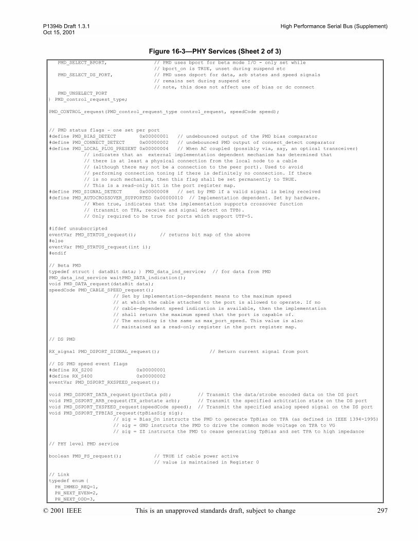
P1394b Draft 1.3.1 High Performance Serial Bus (Supplement)Oct 15, 2001
PMD_SELECT_BPORT, // PMD uses bport for beta mode I/O - only set while // bport_on is TRUE, unset during suspend etc PMD_SELECT_DS_PORT, // PMD uses dsport for data, arb states and speed signals // remains set during suspend etc // note, this does not affect use of bias or dc connect PMD_UNSELECT_PORT PMD_control_request_type;
PMD_CONTROL_request(PMD_control_request_type control_request, speedCode speed);
// PMD status flags - one set per port#define PMD_BIAS_DETECT 0x00000001 // undebounced output of the PMD bias comparator#define PMD_CONNECT_DETECT 0x00000002 // undebounced PMD output of connect_detect comparator#define PMD_LOCAL_PLUG_PRESENT 0x00000004 // When AC coupled (possibly via, say, an optical transceiver) // indicates that an external implementation dependent mechanism has determined that // there is at least a physical connection from the local node to a cable // (although there may not be a connection to the peer port). Used to avoid // performing connection toning if there is definitely no connection. If there // is no such mechanism, then this flag shall be set permanently to TRUE. // This is a read-only bit in the port register map.#define PMD_SIGNAL_DETECT 0x00000008 // set by PMD if a valid signal is being received#define PMD_AUTOCROSSOVER_SUPPORTED 0x00000010 // Implementation dependent. Set by hardware. // When true, indicates that the implementation supports crossover function // (transmit on TPA, receive and signal detect on TPB). // Only required to be true for ports which support UTP-5.
#ifdef unsubscriptedeventVar PMD_STATUS_request(); // returns bit map of the above#elseeventVar PMD_STATUS_request(int i);#endif
// Beta PMDtypedef struct dataBit data; PMD_data_ind_service; // for data from PMDPMD_data_ind_service waitPMD_DATA_indication();void PMD_DATA_request(dataBit data);speedCode PMD_CABLE_SPEED_request(); // Set by implementation-dependent means to the maximum speed // at which the cable attached to the port is allowed to operate. If no // cable-dependent speed indication is available, then the implementation // shall return the maximum speed that the port is capable of. // The encoding is the same as max_port_speed. This value is also // maintained as a read-only register in the port register map.
// DS PMD
RX_signal PMD_DSPORT_SIGNAL_request(); // Return current signal from port
// DS PMD speed event flags#define RX_S200 0x00000001#define RX_S400 0x00000002eventVar PMD_DSPORT_RXSPEED_request();
void PMD_DSPORT_DATA_request(portData pd); // Transmit the data/strobe encoded data on the DS portvoid PMD_DSPORT_ARB_request(TX_arbstate arb); // Transmit the specified arbitration state on the DS portvoid PMD_DSPORT_TXSPEED_request(speedCode speed); // Transmit the specified analog speed signal on the DS portvoid PMD_DSPORT_TPBIAS_request(tpBiasSig sig); // sig = Bias_On instructs the PMD to generate TpBias on TPA (as defined in IEEE 1394-1995) // sig = GND instructs the PMD to drive the common mode voltage on TPA to VG // sig = ZZ instructs the PMD to cease generating TpBias and set TPA to high impedance
// PHY level PMD service
boolean PMD_PS_request(); // TRUE if cable power active // value is maintained in Register 0
// Linktypedef enum PH_IMMED_REQ=1, PH_NEXT_EVEN=2, PH_NEXT_ODD=3,
Figure 16-3PHY Services (Sheet 2 of 3)
© 2001 IEEE This is an unapproved standards draft, subject to change 297
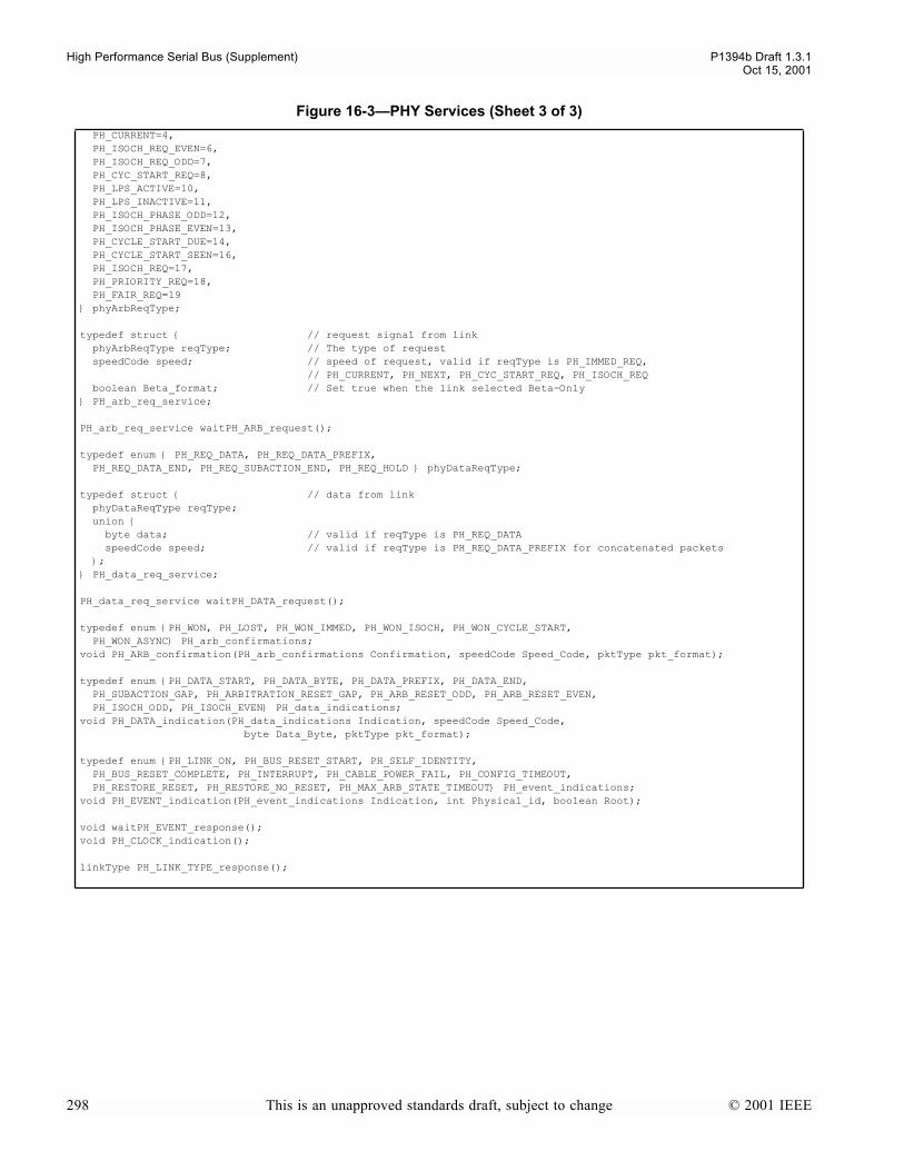
High Performance Serial Bus (Supplement) P1394b Draft 1.3.1Oct 15, 2001
PH_CURRENT=4, PH_ISOCH_REQ_EVEN=6, PH_ISOCH_REQ_ODD=7, PH_CYC_START_REQ=8, PH_LPS_ACTIVE=10, PH_LPS_INACTIVE=11, PH_ISOCH_PHASE_ODD=12, PH_ISOCH_PHASE_EVEN=13, PH_CYCLE_START_DUE=14, PH_CYCLE_START_SEEN=16, PH_ISOCH_REQ=17, PH_PRIORITY_REQ=18, PH_FAIR_REQ=19 phyArbReqType; typedef struct // request signal from link phyArbReqType reqType; // The type of request speedCode speed; // speed of request, valid if reqType is PH_IMMED_REQ, // PH_CURRENT, PH_NEXT, PH_CYC_START_REQ, PH_ISOCH_REQ boolean Beta_format; // Set true when the link selected Beta-Only PH_arb_req_service;
PH_arb_req_service waitPH_ARB_request();
typedef enum PH_REQ_DATA, PH_REQ_DATA_PREFIX, PH_REQ_DATA_END, PH_REQ_SUBACTION_END, PH_REQ_HOLD phyDataReqType;
typedef struct // data from link phyDataReqType reqType; union byte data; // valid if reqType is PH_REQ_DATA speedCode speed; // valid if reqType is PH_REQ_DATA_PREFIX for concatenated packets ; PH_data_req_service;
PH_data_req_service waitPH_DATA_request();
typedef enum PH_WON, PH_LOST, PH_WON_IMMED, PH_WON_ISOCH, PH_WON_CYCLE_START, PH_WON_ASYNC PH_arb_confirmations;void PH_ARB_confirmation(PH_arb_confirmations Confirmation, speedCode Speed_Code, pktType pkt_format);
typedef enum PH_DATA_START, PH_DATA_BYTE, PH_DATA_PREFIX, PH_DATA_END, PH_SUBACTION_GAP, PH_ARBITRATION_RESET_GAP, PH_ARB_RESET_ODD, PH_ARB_RESET_EVEN, PH_ISOCH_ODD, PH_ISOCH_EVEN PH_data_indications;void PH_DATA_indication(PH_data_indications Indication, speedCode Speed_Code, byte Data_Byte, pktType pkt_format);
typedef enum PH_LINK_ON, PH_BUS_RESET_START, PH_SELF_IDENTITY, PH_BUS_RESET_COMPLETE, PH_INTERRUPT, PH_CABLE_POWER_FAIL, PH_CONFIG_TIMEOUT, PH_RESTORE_RESET, PH_RESTORE_NO_RESET, PH_MAX_ARB_STATE_TIMEOUT PH_event_indications;void PH_EVENT_indication(PH_event_indications Indication, int Physical_id, boolean Root);
void waitPH_EVENT_response();void PH_CLOCK_indication();
linkType PH_LINK_TYPE_response();
Figure 16-3PHY Services (Sheet 3 of 3)
298 This is an unapproved standards draft, subject to change © 2001 IEEE
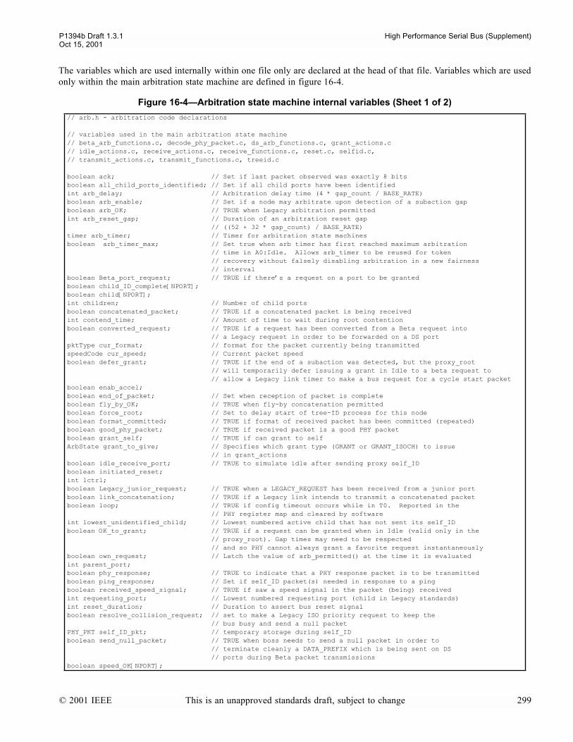
P1394b Draft 1.3.1 High Performance Serial Bus (Supplement)Oct 15, 2001
The variables which are used internally within one file only are declared at the head of that file. Variables which are usedonly within the main arbitration state machine are defined in figure 16-4.
Figure 16-4Arbitration state machine internal variables (Sheet 1 of 2)
// arb.h - arbitration code declarations
// variables used in the main arbitration state machine// beta_arb_functions.c, decode_phy_packet.c, ds_arb_functions.c, grant_actions.c// idle_actions.c, receive_actions.c, receive_functions.c, reset.c, selfid.c,// transmit_actions.c, transmit_functions.c, treeid.c
boolean ack; // Set if last packet observed was exactly 8 bitsboolean all_child_ports_identified; // Set if all child ports have been identifiedint arb_delay; // Arbitration delay time (4 * gap_count / BASE_RATE)boolean arb_enable; // Set if a node may arbitrate upon detection of a subaction gapboolean arb_OK; // TRUE when Legacy arbitration permittedint arb_reset_gap; // Duration of an arbitration reset gap // ((52 + 32 * gap_count) / BASE_RATE)timer arb_timer; // Timer for arbitration state machinesboolean arb_timer_max; // Set true when arb timer has first reached maximum arbitration // time in A0:Idle. Allows arb_timer to be reused for token // recovery without falsely disabling arbitration in a new fairness // intervalboolean Beta_port_request; // TRUE if theres a request on a port to be grantedboolean child_ID_complete[NPORT];boolean child[NPORT];int children; // Number of child portsboolean concatenated_packet; // TRUE if a concatenated packet is being receivedint contend_time; // Amount of time to wait during root contentionboolean converted_request; // TRUE if a request has been converted from a Beta request into // a Legacy request in order to be forwarded on a DS portpktType cur_format; // format for the packet currently being transmittedspeedCode cur_speed; // Current packet speedboolean defer_grant; // TRUE if the end of a subaction was detected, but the proxy_root // will temporarily defer issuing a grant in Idle to a beta request to // allow a Legacy link timer to make a bus request for a cycle start packetboolean enab_accel;boolean end_of_packet; // Set when reception of packet is completeboolean fly_by_OK; // TRUE when fly-by concatenation permittedboolean force_root; // Set to delay start of tree-ID process for this nodeboolean format_committed; // TRUE if format of received packet has been committed (repeated)boolean good_phy_packet; // TRUE if received packet is a good PHY packetboolean grant_self; // TRUE if can grant to selfArbState grant_to_give; // Specifies which grant type (GRANT or GRANT_ISOCH) to issue // in grant_actionsboolean idle_receive_port; // TRUE to simulate idle after sending proxy self_IDboolean initiated_reset;int lctrl;boolean Legacy_junior_request; // TRUE when a LEGACY_REQUEST has been received from a junior port boolean link_concatenation; // TRUE if a Legacy link intends to transmit a concatenated packetboolean loop; // TRUE if config timeout occurs while in T0. Reported in the // PHY register map and cleared by softwareint lowest_unidentified_child; // Lowest numbered active child that has not sent its self_IDboolean OK_to_grant; // TRUE if a request can be granted when in Idle (valid only in the // proxy_root). Gap times may need to be respected // and so PHY cannot always grant a favorite request instantaneouslyboolean own_request; // Latch the value of arb_permitted() at the time it is evaluatedint parent_port;boolean phy_response; // TRUE to indicate that a PHY response packet is to be transmittedboolean ping_response; // Set if self_ID packet(s) needed in response to a pingboolean received_speed_signal; // TRUE if saw a speed signal in the packet (being) receivedint requesting_port; // Lowest numbered requesting port (child in Legacy standards)int reset_duration; // Duration to assert bus reset signalboolean resolve_collision_request; // set to make a Legacy ISO priority request to keep the // bus busy and send a null packetPHY_PKT self_ID_pkt; // temporary storage during self_IDboolean send_null_packet; // TRUE when boss needs to send a null packet in order to // terminate cleanly a DATA_PREFIX which is being sent on DS // ports during Beta packet transmissionsboolean speed_OK[NPORT];
© 2001 IEEE This is an unapproved standards draft, subject to change 299
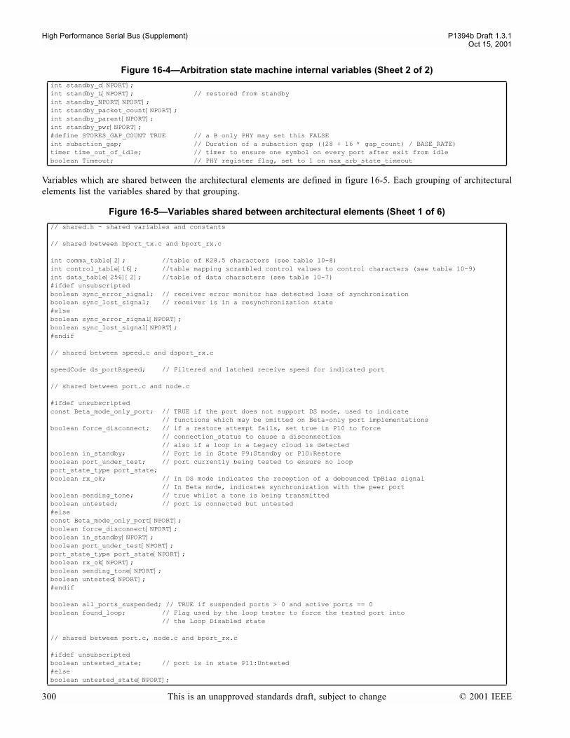
High Performance Serial Bus (Supplement) P1394b Draft 1.3.1Oct 15, 2001
Variables which are shared between the architectural elements are defined in figure 16-5. Each grouping of architecturalelements list the variables shared by that grouping.
int standby_c[NPORT];int standby_L[NPORT]; // restored from standbyint standby_NPORT[NPORT];int standby_packet_count[NPORT];int standby_parent[NPORT];int standby_pwr[NPORT];#define STORES_GAP_COUNT TRUE // a B only PHY may set this FALSEint subaction_gap; // Duration of a subaction gap ((28 + 16 * gap_count) / BASE_RATE)timer time_out_of_idle; // timer to ensure one symbol on every port after exit from idleboolean Timeout; // PHY register flag, set to 1 on max_arb_state_timeout
Figure 16-5Variables shared between architectural elements (Sheet 1 of 6)
// shared.h - shared variables and constants
// shared between bport_tx.c and bport_rx.c
int comma_table[2]; //table of K28.5 characters (see table 10-8)int control_table[16]; //table mapping scrambled control values to control characters (see table 10-9)int data_table[256][2]; //table of data characters (see table 10-7)#ifdef unsubscriptedboolean sync_error_signal; // receiver error monitor has detected loss of synchronizationboolean sync_lost_signal; // receiver is in a resynchronization state#elseboolean sync_error_signal[NPORT];boolean sync_lost_signal[NPORT];#endif
// shared between speed.c and dsport_rx.c
speedCode ds_portRspeed; // Filtered and latched receive speed for indicated port
// shared between port.c and node.c
#ifdef unsubscriptedconst Beta_mode_only_port; // TRUE if the port does not support DS mode, used to indicate // functions which may be omitted on Beta-only port implementationsboolean force_disconnect; // if a restore attempt fails, set true in P10 to force // connection_status to cause a disconnection // also if a loop in a Legacy cloud is detectedboolean in_standby; // Port is in State P9:Standby or P10:Restoreboolean port_under_test; // port currently being tested to ensure no loopport_state_type port_state;boolean rx_ok; // In DS mode indicates the reception of a debounced TpBias signal // In Beta mode, indicates synchronization with the peer portboolean sending_tone; // true whilst a tone is being transmittedboolean untested; // port is connected but untested#elseconst Beta_mode_only_port[NPORT];boolean force_disconnect[NPORT];boolean in_standby[NPORT];boolean port_under_test[NPORT];port_state_type port_state[NPORT];boolean rx_ok[NPORT];boolean sending_tone[NPORT];boolean untested[NPORT];#endif
boolean all_ports_suspended; // TRUE if suspended ports > 0 and active ports == 0boolean found_loop; // Flag used by the loop tester to force the tested port into // the Loop Disabled state
// shared between port.c, node.c and bport_rx.c
#ifdef unsubscriptedboolean untested_state; // port is in state P11:Untested#elseboolean untested_state[NPORT];
Figure 16-4Arbitration state machine internal variables (Sheet 2 of 2)
300 This is an unapproved standards draft, subject to change © 2001 IEEE
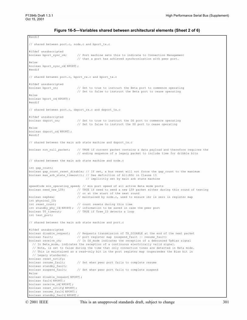
P1394b Draft 1.3.1 High Performance Serial Bus (Supplement)Oct 15, 2001
#endif
// shared between port.c, node.c and bport_tx.c
#ifdef unsubscriptedboolean bport_sync_ok; // Port machine sets this to indicate to Connection Management // that a port has achieved synchronization with peer port.#elseboolean bport_sync_ok[NPORT];#endif
// shared between port.c, bport_rx.c and bport_tx.c
#ifdef unsubscriptedboolean bport_on; // Set to true to instruct the Beta port to commence operating // Set to false to instruct the Beta port to cease operating#elseboolean bport_on[NPORT];#endif
// shared between port.c, dsport_rx.c and dsport_tx.c
#ifdef unsubscriptedboolean dsport_on; // Set to true to instruct the DS port to commence operating // Set to false to instruct the DS port to cease operating#elseboolean dsport_on[NPORT];#endif
// shared between the main arb state machine and dsport_tx.c
boolean non_null_packet; // TRUE if current packet contains a data payload and therefore requires the // ending sequence of a legacy packet to include time for dribble bits
// shared between the main arb state machine and node.c
int gap_count;boolean gap_count_reset_disable; // If set, a bus reset will not force the gap_count to the maximumboolean max_arb_state_timeout(); // See definition of All:R0c in Clause 13 // implicitly set by main arb state machine speedCode min_operating_speed; // min port speed of all active Beta mode portsboolean need_new_LTP; // TRUE if need to send a new LTP packet either during this round of testing // or at the start of the next roundboolean nephew; // maintained by node.c, used to ensure ibr is zero in register mapint physical_ID;int reset_count; // count resets during this timeint standby_phy_ID[NPORT]; // information to be saved in case the peer port boolean T0_timeout; // TRUE if Tree_ID detects a loopint test_port;
// shared between the main arb state machine and port.c
#ifdef unsubscriptedboolean disable_request; // Requests transmission of TX_DISABLE at the end of the next packetboolean fault; // port register map (suspend_fault || resume_fault) boolean receive_ok; // In DS_mode indicates the reception of a debounced TpBias signal // In Beta_mode, indicates the reception of a continuous electrically valid signal. // Note, is set to false during the time that only connection tones are detected in Beta mode. // This is maintained as a read-only bit in the port register map (supersedes the Bias bit in // Legacy standards).boolean reset_notify;boolean resume_fault; // Set when peer port fails to complete resumeboolean standby_fault;boolean suspend_fault; // Set when peer port fails to complete suspend#elseboolean disable_request[NPORT];boolean fault[NPORT]; boolean receive_ok[NPORT];boolean reset_notify[NPORT];boolean resume_fault[NPORT];boolean standby_fault[NPORT];
Figure 16-5Variables shared between architectural elements (Sheet 2 of 6)
© 2001 IEEE This is an unapproved standards draft, subject to change 301
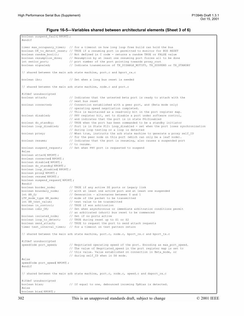
High Performance Serial Bus (Supplement) P1394b Draft 1.3.1Oct 15, 2001
boolean suspend_fault[NPORT];#endif
timer max_occupancy_timer; // for a timeout on how long loop free build can hold the busboolean OK_to_detect_reset; // TRUE if a resuming port is permitted to monitor for BUS RESETboolean random_bool(); // Not defined in C code - returns a random TRUE or FALSE valueboolean resumption_done; // Resumption by at least one resuming port forces all to be doneint senior_port; // port number of the port pointing towards proxy_root boolean signaled; // Indicate transmission of TX_DISABLE_NOTIFY, TX_SUSPEND or TX_STANDBY
// shared between the main arb state machine, port.c and bport_rx.c
boolean ibr; // Set when a long bus reset is needed
// shared between the main arb state machine, node.c and port.c
#ifdef unsubscriptedboolean attach; // Indicates that the untested beta port is ready to attach with the // next bus reset boolean connected; // Connection established with a peer port, and (Beta mode only) // operating speed negotiation completed. // This is maintained as a read-only bit in the port register map.boolean disabled; // PHY register bit, set to disable a port under software control, // and indicates that the port is in state P6:Disabledboolean do_standby; // TRUE when the port has been commanded to be a standby initiatorboolean loop_disabled; // Port is in State P12: Loop_disabled - set when the port loses synchronization // during loop testing or a loop is detectedboolean proxy; // When true, instructs the arb state machine to generate a proxy self_ID // for the peer node on this port (which can only be a leaf node).boolean resume; // Indicates that the port is resuming, also causes a suspended port // to resume.boolean suspend_request; // Set when PHY port is requested to suspend#elseboolean attach[NPORT];boolean connected[NPORT]; boolean disabled[NPORT];boolean do_standby[NPORT];boolean loop_disabled[NPORT];boolean proxy[NPORT];boolean resume[NPORT]; boolean suspend_request[NPORT];#endifboolean border_node; // TRUE if any active DS ports or Legacy linkboolean boundary_node; // with at least one active port and at least one suspendedint HR_G; // Generation - alternates between 0 and 1LTP_mode_type HR_mode; // mode of the packet to be transmittedint HR_test_value; // test value to be transmittedboolean in_control; // TRUE if won arbitrationboolean isbr_OK; // Set when asynchronous or immediate arbitration conditions permit // an arbitrated (short) bus reset to be commencedboolean isolated_node; // Set if no ports activeboolean loop_to_detect; // TRUE during reset up to S1 or S2boolean send_attach; // TRUE to request the port to send attach requeststimer test_interval_timer; // for a timeout on test pattern return
// shared between the main arb state machine, port.c, node.c, bport_rx.c and bport_tx.c
#ifdef unsubscriptedspeedCode port_speed; // Negotiated operating speed of the port. Encoding as max_port_speed. // The value of Negotiated_speed in the port register map is set to // this value. Value established on connection in Beta_mode, or // during self_ID when in DS mode.#elsespeedCode port_speed[NPORT];#endif
// shared between the main arb state machine, port.c, node.c, speed.c and dsport_rx.c
#ifdef unsubscriptedboolean bias; // If equal to one, debounced incoming TpBias is detected. #elseboolean bias[NPORT];
Figure 16-5Variables shared between architectural elements (Sheet 3 of 6)
302 This is an unapproved standards draft, subject to change © 2001 IEEE
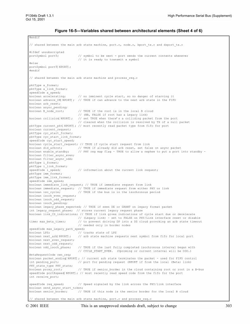
P1394b Draft 1.3.1 High Performance Serial Bus (Supplement)Oct 15, 2001
#endif
// shared between the main arb state machine, port.c, node.c, bport_tx.c and dsport_tx.c
#ifdef unsubscriptedportSymbol portT; // symbol to be sent - port sends the current contents whenever // it is ready to transmit a symbol#elseportSymbol portT[NPORT];#endif
// shared between the main arb state machine and process_req.c
pktType a_format;pktType a_link_format;speedCode a_speed;boolean accelerating; // no imminent cycle start, so no danger of starving itboolean advance_OK[NPORT]; // TRUE if can advance to the next arb state in the FIFOboolean arb_reset;boolean async_pending;boolean B_node_root; // TRUE if the root is in the local B cloud // (NB, FALSE if root has a Legacy link)boolean collision[NPORT]; // set TRUE when theres a colliding packet from the port // cleared when the collision is resolved by TX of a null packetpktType current_pkt[NPORT]; // most recently read packet type from fifo for portboolean current_request;pktType cyc_start_format;pktType cyc_start_link_format;speedCode cyc_start_speed;boolean cycle_start_request; // TRUE if cycle start request from linkboolean did_arbrst; // TRUE if already did arb reset, set false on async packetboolean enable_standby; // PHY reg map flag - TRUE to allow a nephew to put a port into standby -boolean filter_async_even;boolean filter_async_odd;pktType i_format;pktType i_link_format;speedCode i_speed; // information about the current link request;pktType imm_format;pktType imm_link_format;speedCode imm_speed;boolean immediate_link_request; // TRUE if immediate request from linkboolean immediate_request; // TRUE if immediate request from either PHY or linkboolean iso_cycle; // TRUE if the bus is in the isochronous periodboolean isoch_even_request;boolean isoch_odd_request;boolean isoch_pending;boolean legacy_phase_expected; // TRUE if seen DE or GRANT on legacy format packetint legacy_request_phase; // stores current legacy request phaseboolean link_CS_indications; // TRUE if link gives indications of cycle start due or decelerate // (Legacy link) - set to FALSE on PHY/Link interface reset or disabletimer max_beta_timer; // to prevent driving DP into a DS cloud provoking an arb state timeout // needed only in border nodesspeedCode max_Legacy_path_speed;boolean LPS; // tracks state of LPSboolean next_arb[NPORT]; // arb state machine requests next symbol from fifo for local portboolean next_even_request;boolean next_odd_request;boolean odd_isoch_phase; // TRUE if the last fully completed isochronous interval began with // CYCLE_START_EVEN. (Upcoming or current interval will be ODD.)BetaRequestCode own_req;boolean packet_ending[NPORT]; // current arb state terminates the packet - used for FIFO controlint pending_port; // port for pending request (NPORT if from the local (Beta) link)PHY_state_type PHY_state; boolean proxy_root; // TRUE if senior_border in the cloud containing root or root in a B-busspeedCode portRspeed[NPORT]; // most recently read speed code from the fifo for the portint receive_port;
speedCode req_speed; // Speed signaled by the link across the PHY/link interfaceboolean send_async_start_token;boolean senior_border; // TRUE if this node is the senior border for the local B cloud
// shared between the main arb state machine, port.c and process_req.c
Figure 16-5Variables shared between architectural elements (Sheet 4 of 6)
© 2001 IEEE This is an unapproved standards draft, subject to change 303

High Performance Serial Bus (Supplement) P1394b Draft 1.3.1Oct 15, 2001
boolean immediate_phy_request; // TRUE if immediate request from the PHYboolean odd_async_phase; // TRUE if last received arb reset was ARB_RESET_ODD
// shared between the main arb state machine, port.c, node.c and process_req.c
boolean immediate_restore_request; // TRUE if immediate request to restore on the nephewboolean isbr; // Set when an arbitrated (short) bus reset should be attemptedboolean restore_request; // TRUE if requested the bus in order to complete a port restore#ifdef unsubscriptedboolean active; // Indicates that the port is in state P2:Active // (set by state machine transitions to/from P2)boolean Beta_mode; // Set if the port has determined that it is operating in Beta mode, unset otherwise // (i.e. when operating in DS-Mode, or when in P0:disconnected). // This is maintained as a read-only bit in the port register map.ArbState portRarb; // most recently read arb state from fifo for portboolean restore;#elseboolean active[NPORT];boolean Beta_mode[NPORT+1]; // Beta_mode[NPORT] always falseArbState portRarb[NPORT];boolean restore[NPORT];#endif
// shared between the main arb state machine, port.c, node.c and bport_rx.c
boolean bus_initialize_active; // Set while the PHY is initializing the bus
// shared between the main arb state machine, node.c and process_req.c
#ifdef unsubscriptedbyte current_data; // most recently read data from the fifo for the port#elsebyte current_data[NPORT];#endif
breq_type breq;linkType link; // global status variable set by the PHY/Link interface // note, this does not change during normal operation // if this changes, then the PHY is power reset // Note also that changes to LPS do NOT affect this variableBetaRequestCode receive_req[NPORT]; //track latest requests received on each portboolean root; // TRUE if root node
// shared between node.c and process_req.c
boolean loop_test_request; // TRUE if requested the bus in order to test for loops
// shared between the main arb state machine, bport_rx.c, and process_req.c
boolean B_bus; // TRUE if no Legacy nodes (including Legacy Links) on bus#define FIFO_DEPTH 5 // depth of receive FIFO
// shared between the main arb state machine, bport_rx.c, dsport_rx.c and process_req.c
#ifdef unsubscriptedint fifo_rd_ptr; // pointer to received character in fifoint fifo_wr_ptr; // only updated by the appropriate port#elseint fifo_rd_ptr[NPORT];int fifo_wr_ptr[NPORT];#endif
// shared between the main arb state machine, dsport_tx.c, and process_req.c
boolean DS_stuck; // TRUE if there might be a DS port stuck in DP somewhere on the bus
// shared between bport_rx.c, dsport_rx.c and process_req.c
#ifdef unsubscriptedportSymbol portR[FIFO_DEPTH]; // symbol received by port machine
Figure 16-5Variables shared between architectural elements (Sheet 5 of 6)
304 This is an unapproved standards draft, subject to change © 2001 IEEE

P1394b Draft 1.3.1 High Performance Serial Bus (Supplement)Oct 15, 2001
#elseportSymbol portR[NPORT][FIFO_DEPTH];#endif
// shared between bport_tx.c, port.c and process_req.c
#ifdef unsubscriptedBetaRequestCode arbreqT; // arbitration request to send#elseBetaRequestCode arbreqT[NPORT];#endif
// shared between all modules
boolean power_reset; // TRUE during power reset, goes false at the end of power reset
#include proto.h // last header, get the prototypes for C code checking purposes
Figure 16-5Variables shared between architectural elements (Sheet 6 of 6)
© 2001 IEEE This is an unapproved standards draft, subject to change 305
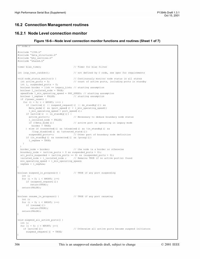
High Performance Serial Bus (Supplement) P1394b Draft 1.3.1Oct 15, 2001
16.2 Connection Management routines
16.2.1 Node Level connection monitor
Figure 16-6Node level connection monitor functions and routines (Sheet 1 of 7)
// node.c
#include 1394.h#include data_structures.h#include phy_services.h#include shared.h
timer bias_timer; // Timer for bias filter
int loop_test_random(); // not defined by C code, see spec for requirements
void node_status_monitor() // Continuously monitor node status in all states int active_ports = 0; // count of active ports, including ports in standby int i, suspended_ports = 0; boolean border = link == Legacy_Link; // starting assumption boolean l_isolated_node = TRUE; speedCode l_min_operating_speed = PHY_SPEED; // starting assumption boolean l_nephew = FALSE; // starting assumption if (!power_reset) for (i = 0; i < NPORT; i++) if ((active[i] || suspend_request[i] || do_standby[i]) && Beta_mode[i] && (port_speed[i] < l_min_operating_speed)) l_min_operating_speed = port_speed[i]; if (active[i] || in_standby[i]) active_ports++; // Necessary to deduce boundary node status l_isolated_node = FALSE; if (!Beta_mode[i]) // active port is operating in Legacy mode border = TRUE; else if (connected[i] && !disabled[i] && !in_standby[i] && !loop_disabled[i] && !untested_state[i]) suspended_ports++; // Other part of boundary node definition if (in_standby[i] && connected[i] && !proxy[i]) l_nephew = TRUE; border_node = border; // the node is a border or otherwise boundary_node = (active_ports > 0 && suspended_ports > 0); all_ports_suspended = (active_ports == 0) && (suspended_ports > 0); isolated_node = l_isolated_node ; // Remains TRUE if no active port(s) found min_operating_speed = l_min_operating_speed; nephew = l_nephew;
boolean suspend_in_progress() // TRUE if any port suspending int i; for (i = 0; i < NPORT; i++) if (suspend_request[i]) return(TRUE); return(FALSE);
boolean resume_in_progress() // TRUE if any port resuming int i; for (i = 0; i < NPORT; i++) if (resume[i]) return(TRUE); return(FALSE);
void suspend_all_active_ports() int j; for (j = 0; j < NPORT; j++) if (active[j]) // Otherwise all active ports become suspend initiators suspend_request[j] = TRUE;
306 This is an unapproved standards draft, subject to change © 2001 IEEE

P1394b Draft 1.3.1 High Performance Serial Bus (Supplement)Oct 15, 2001
void resume_all_ports() int j; for (j = 0; j < NPORT; j++) if ((port_state[j] == P1) || (port_state[j] == P3) || (port_state[j] == P4) || (port_state[j] == P5)) resume[j] = TRUE; // Resume all suspended ports
boolean resume_rx_OK() int j; boolean resume_rx_OK_val = TRUE; // Assume this is true until proven false for (j=0; j < NPORT; j++) resume_rx_OK_val &= (!resume[j] || rx_ok[j]); // Note that for resuming Beta ports presence of receive_ok is not // enough, need to allow sufficient time for port sync also. For // DS ports, rx_ok indicates state of detected bias
return (resume_rx_OK_val);
boolean restore_in_progress() // TRUE if any port restoring int i; for (i = 0; i < NPORT; i++) if (restore[i]) return(TRUE); return(FALSE);
void restore_port() int j; for (j = 0; j < NPORT; j++) if (in_standby[j] && connected[j] && !proxy[j]) restore[j] = TRUE; // Restore port in standby (if any) if on leaf
void bias_status() // Continuously running bias update code static boolean bias_filter[NPORT]; // TRUE when applying hysteresis to bias_detect circuit int i; if (power_reset) for (i = 0; i < NPORT; i++) bias[i] = bias_filter[i] = FALSE; while (power_reset) ; return; for (i = 0; i < NPORT; i++) if (!Beta_mode_only_port[i]) if (sending_tone[i]) bias_filter[i] = FALSE; // abandon bias filtering on this port whilst sending a tone continue; // and move on to next port if (!(PMD_STATUS_request(i) & PMD_BIAS_DETECT)) // 200 - 300 ns hysteresis recommended // see 4.4.4 of 1394a for requirements bias_filter[i] = FALSE; bias[i] = FALSE ; // Report immediately else if (bias_filter[i]) // Filtering positive bias transition? if (bias_timer >= BIAS_FILTER_TIME) bias_filter[i] = FALSE; // Done filtering bias[i] = TRUE; // Confirm new value in PHY register bit else if ( !disabled[i] // detected and reported bias differ on enabled port? && (PMD_STATUS_request(i) & PMD_BIAS_DETECT) != bias[i]) bias_filter[i] = TRUE; // Yes, start a filtering period bias_timer = 0;
void send_LTP() PHY_PKT tx_phy_pkt;
Figure 16-6Node level connection monitor functions and routines (Sheet 2 of 7)
© 2001 IEEE This is an unapproved standards draft, subject to change 307
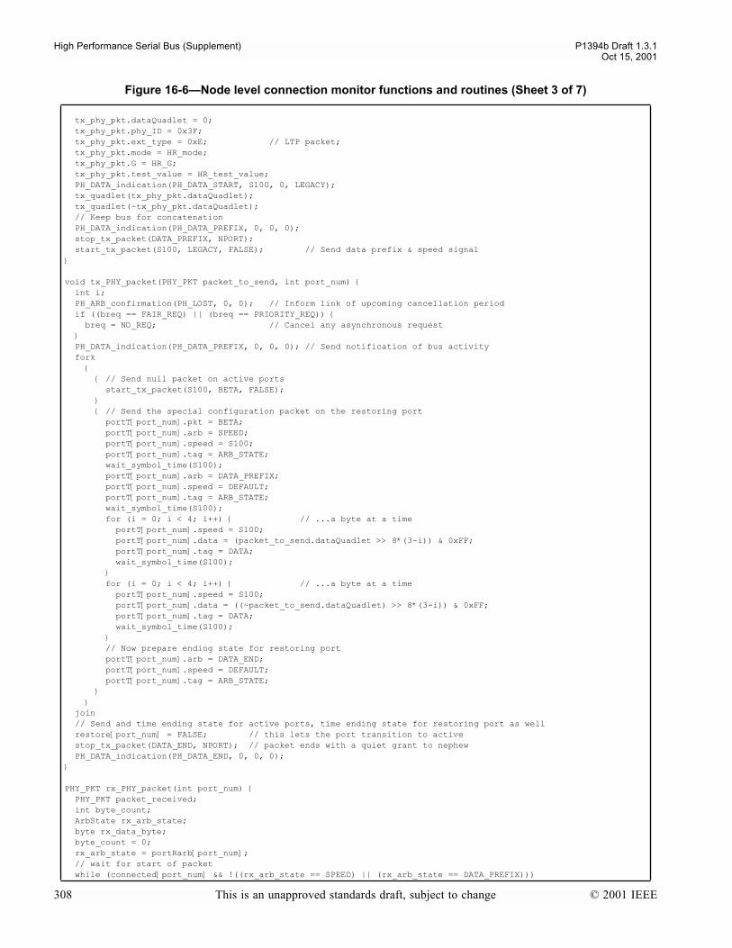
High Performance Serial Bus (Supplement) P1394b Draft 1.3.1Oct 15, 2001
tx_phy_pkt.dataQuadlet = 0; tx_phy_pkt.phy_ID = 0x3F; tx_phy_pkt.ext_type = 0xE; // LTP packet; tx_phy_pkt.mode = HR_mode; tx_phy_pkt.G = HR_G; tx_phy_pkt.test_value = HR_test_value; PH_DATA_indication(PH_DATA_START, S100, 0, LEGACY); tx_quadlet(tx_phy_pkt.dataQuadlet); tx_quadlet(~tx_phy_pkt.dataQuadlet); // Keep bus for concatenation PH_DATA_indication(PH_DATA_PREFIX, 0, 0, 0); stop_tx_packet(DATA_PREFIX, NPORT); start_tx_packet(S100, LEGACY, FALSE); // Send data prefix & speed signal
void tx_PHY_packet(PHY_PKT packet_to_send, int port_num) int i; PH_ARB_confirmation(PH_LOST, 0, 0); // Inform link of upcoming cancellation period if ((breq == FAIR_REQ) || (breq == PRIORITY_REQ)) breq = NO_REQ; // Cancel any asynchronous request PH_DATA_indication(PH_DATA_PREFIX, 0, 0, 0); // Send notification of bus activity fork // Send null packet on active ports start_tx_packet(S100, BETA, FALSE); // Send the special configuration packet on the restoring port portT[port_num].pkt = BETA; portT[port_num].arb = SPEED; portT[port_num].speed = S100; portT[port_num].tag = ARB_STATE; wait_symbol_time(S100); portT[port_num].arb = DATA_PREFIX; portT[port_num].speed = DEFAULT; portT[port_num].tag = ARB_STATE; wait_symbol_time(S100); for (i = 0; i < 4; i++) // ...a byte at a time portT[port_num].speed = S100; portT[port_num].data = (packet_to_send.dataQuadlet >> 8*(3-i)) & 0xFF; portT[port_num].tag = DATA; wait_symbol_time(S100); for (i = 0; i < 4; i++) // ...a byte at a time portT[port_num].speed = S100; portT[port_num].data = ((~packet_to_send.dataQuadlet) >> 8*(3-i)) & 0xFF; portT[port_num].tag = DATA; wait_symbol_time(S100); // Now prepare ending state for restoring port portT[port_num].arb = DATA_END; portT[port_num].speed = DEFAULT; portT[port_num].tag = ARB_STATE; join // Send and time ending state for active ports, time ending state for restoring port as well restore[port_num] = FALSE; // this lets the port transition to active stop_tx_packet(DATA_END, NPORT); // packet ends with a quiet grant to nephew PH_DATA_indication(PH_DATA_END, 0, 0, 0);
PHY_PKT rx_PHY_packet(int port_num) PHY_PKT packet_received; int byte_count; ArbState rx_arb_state; byte rx_data_byte; byte_count = 0; rx_arb_state = portRarb[port_num]; // wait for start of packet while (connected[port_num] && !((rx_arb_state == SPEED) || (rx_arb_state == DATA_PREFIX)))
Figure 16-6Node level connection monitor functions and routines (Sheet 3 of 7)
308 This is an unapproved standards draft, subject to change © 2001 IEEE
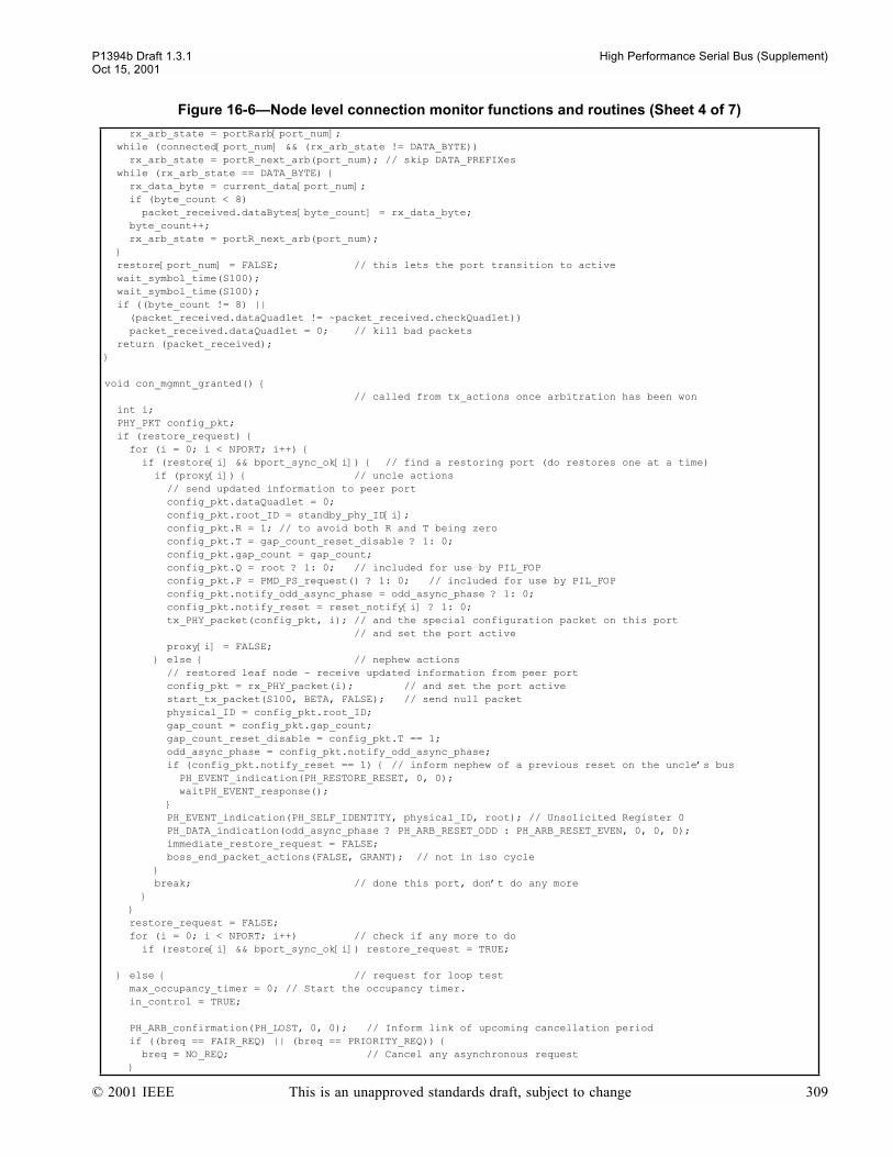
P1394b Draft 1.3.1 High Performance Serial Bus (Supplement)Oct 15, 2001
rx_arb_state = portRarb[port_num]; while (connected[port_num] && (rx_arb_state != DATA_BYTE)) rx_arb_state = portR_next_arb(port_num); // skip DATA_PREFIXes while (rx_arb_state == DATA_BYTE) rx_data_byte = current_data[port_num]; if (byte_count < 8) packet_received.dataBytes[byte_count] = rx_data_byte; byte_count++; rx_arb_state = portR_next_arb(port_num); restore[port_num] = FALSE; // this lets the port transition to active wait_symbol_time(S100); wait_symbol_time(S100); if ((byte_count != 8) || (packet_received.dataQuadlet != ~packet_received.checkQuadlet)) packet_received.dataQuadlet = 0; // kill bad packets return (packet_received);
void con_mgmnt_granted() // called from tx_actions once arbitration has been won int i; PHY_PKT config_pkt; if (restore_request) for (i = 0; i < NPORT; i++) if (restore[i] && bport_sync_ok[i]) // find a restoring port (do restores one at a time) if (proxy[i]) // uncle actions // send updated information to peer port config_pkt.dataQuadlet = 0; config_pkt.root_ID = standby_phy_ID[i]; config_pkt.R = 1; // to avoid both R and T being zero config_pkt.T = gap_count_reset_disable ? 1: 0; config_pkt.gap_count = gap_count; config_pkt.Q = root ? 1: 0; // included for use by PIL_FOP config_pkt.P = PMD_PS_request() ? 1: 0; // included for use by PIL_FOP config_pkt.notify_odd_async_phase = odd_async_phase ? 1: 0; config_pkt.notify_reset = reset_notify[i] ? 1: 0; tx_PHY_packet(config_pkt, i); // and the special configuration packet on this port // and set the port active proxy[i] = FALSE; else // nephew actions // restored leaf node - receive updated information from peer port config_pkt = rx_PHY_packet(i); // and set the port active start_tx_packet(S100, BETA, FALSE); // send null packet physical_ID = config_pkt.root_ID; gap_count = config_pkt.gap_count; gap_count_reset_disable = config_pkt.T == 1; odd_async_phase = config_pkt.notify_odd_async_phase; if (config_pkt.notify_reset == 1) // inform nephew of a previous reset on the uncles bus PH_EVENT_indication(PH_RESTORE_RESET, 0, 0); waitPH_EVENT_response(); PH_EVENT_indication(PH_SELF_IDENTITY, physical_ID, root); // Unsolicited Register 0 PH_DATA_indication(odd_async_phase ? PH_ARB_RESET_ODD : PH_ARB_RESET_EVEN, 0, 0, 0); immediate_restore_request = FALSE; boss_end_packet_actions(FALSE, GRANT); // not in iso cycle break; // done this port, dont do any more restore_request = FALSE; for (i = 0; i < NPORT; i++) // check if any more to do if (restore[i] && bport_sync_ok[i]) restore_request = TRUE;
else // request for loop test max_occupancy_timer = 0; // Start the occupancy timer. in_control = TRUE;
PH_ARB_confirmation(PH_LOST, 0, 0); // Inform link of upcoming cancellation period if ((breq == FAIR_REQ) || (breq == PRIORITY_REQ)) breq = NO_REQ; // Cancel any asynchronous request
Figure 16-6Node level connection monitor functions and routines (Sheet 4 of 7)
© 2001 IEEE This is an unapproved standards draft, subject to change 309
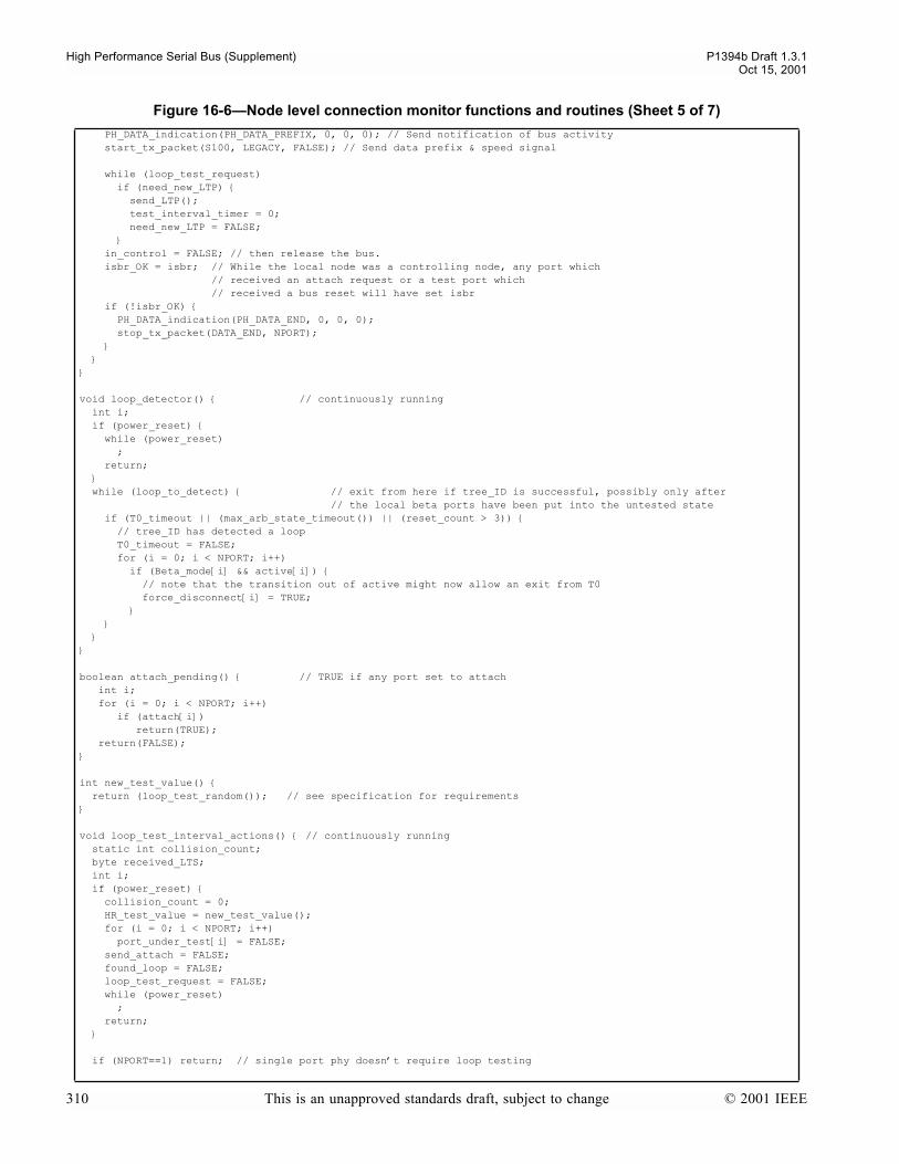
High Performance Serial Bus (Supplement) P1394b Draft 1.3.1Oct 15, 2001
PH_DATA_indication(PH_DATA_PREFIX, 0, 0, 0); // Send notification of bus activity start_tx_packet(S100, LEGACY, FALSE); // Send data prefix & speed signal
while (loop_test_request) if (need_new_LTP) send_LTP(); test_interval_timer = 0; need_new_LTP = FALSE; in_control = FALSE; // then release the bus. isbr_OK = isbr; // While the local node was a controlling node, any port which // received an attach request or a test port which // received a bus reset will have set isbr if (!isbr_OK) PH_DATA_indication(PH_DATA_END, 0, 0, 0); stop_tx_packet(DATA_END, NPORT);
void loop_detector() // continuously running int i; if (power_reset) while (power_reset) ; return; while (loop_to_detect) // exit from here if tree_ID is successful, possibly only after // the local beta ports have been put into the untested state if (T0_timeout || (max_arb_state_timeout()) || (reset_count > 3)) // tree_ID has detected a loop T0_timeout = FALSE; for (i = 0; i < NPORT; i++) if (Beta_mode[i] && active[i]) // note that the transition out of active might now allow an exit from T0 force_disconnect[i] = TRUE;
boolean attach_pending() // TRUE if any port set to attach int i; for (i = 0; i < NPORT; i++) if (attach[i]) return(TRUE); return(FALSE);
int new_test_value() return (loop_test_random()); // see specification for requirements
void loop_test_interval_actions() // continuously running static int collision_count; byte received_LTS; int i; if (power_reset) collision_count = 0; HR_test_value = new_test_value(); for (i = 0; i < NPORT; i++) port_under_test[i] = FALSE; send_attach = FALSE; found_loop = FALSE; loop_test_request = FALSE; while (power_reset) ; return;
if (NPORT==1) return; // single port phy doesnt require loop testing
Figure 16-6Node level connection monitor functions and routines (Sheet 5 of 7)
310 This is an unapproved standards draft, subject to change © 2001 IEEE
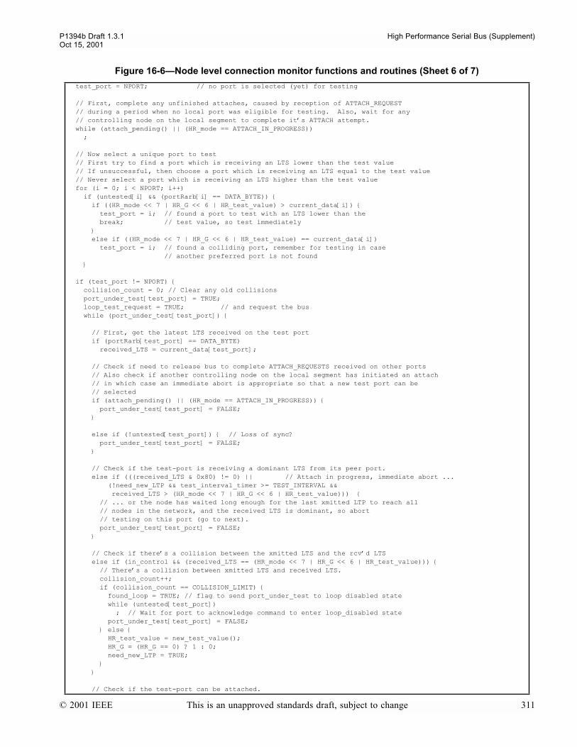
P1394b Draft 1.3.1 High Performance Serial Bus (Supplement)Oct 15, 2001
test_port = NPORT; // no port is selected (yet) for testing
// First, complete any unfinished attaches, caused by reception of ATTACH_REQUEST // during a period when no local port was eligible for testing. Also, wait for any // controlling node on the local segment to complete its ATTACH attempt. while (attach_pending() || (HR_mode == ATTACH_IN_PROGRESS)) ;
// Now select a unique port to test // First try to find a port which is receiving an LTS lower than the test value // If unsuccessful, then choose a port which is receiving an LTS equal to the test value // Never select a port which is receiving an LTS higher than the test value for (i = 0; i < NPORT; i++) if (untested[i] && (portRarb[i] == DATA_BYTE)) if ((HR_mode << 7 | HR_G << 6 | HR_test_value) > current_data[i]) test_port = i; // found a port to test with an LTS lower than the break; // test value, so test immediately else if ((HR_mode << 7 | HR_G << 6 | HR_test_value) == current_data[i]) test_port = i; // found a colliding port, remember for testing in case // another preferred port is not found
if (test_port != NPORT) collision_count = 0; // Clear any old collisions port_under_test[test_port] = TRUE; loop_test_request = TRUE; // and request the bus while (port_under_test[test_port])
// First, get the latest LTS received on the test port if (portRarb[test_port] == DATA_BYTE) received_LTS = current_data[test_port]; // Check if need to release bus to complete ATTACH_REQUESTS received on other ports // Also check if another controlling node on the local segment has initiated an attach // in which case an immediate abort is appropriate so that a new test port can be // selected if (attach_pending() || (HR_mode == ATTACH_IN_PROGRESS)) port_under_test[test_port] = FALSE;
else if (!untested[test_port]) // Loss of sync? port_under_test[test_port] = FALSE;
// Check if the test-port is receiving a dominant LTS from its peer port. else if (((received_LTS & 0x80) != 0) || // Attach in progress, immediate abort ... (!need_new_LTP && test_interval_timer >= TEST_INTERVAL && received_LTS > (HR_mode << 7 | HR_G << 6 | HR_test_value))) // ... or the node has waited long enough for the last xmitted LTP to reach all // nodes in the network, and the received LTS is dominant, so abort // testing on this port (go to next). port_under_test[test_port] = FALSE;
// Check if theres a collision between the xmitted LTS and the rcvd LTS else if (in_control && (received_LTS == (HR_mode << 7 | HR_G << 6 | HR_test_value))) // Theres a collision between xmitted LTS and received LTS. collision_count++; if (collision_count == COLLISION_LIMIT) found_loop = TRUE; // flag to send port_under_test to loop disabled state while (untested[test_port]) ; // Wait for port to acknowledge command to enter loop_disabled state port_under_test[test_port] = FALSE; else HR_test_value = new_test_value(); HR_G = (HR_G == 0) ? 1 : 0; need_new_LTP = TRUE;
// Check if the test-port can be attached.
Figure 16-6Node level connection monitor functions and routines (Sheet 6 of 7)
© 2001 IEEE This is an unapproved standards draft, subject to change 311

High Performance Serial Bus (Supplement) P1394b Draft 1.3.1Oct 15, 2001
16.2.2 Port connection manager actions and conditions
else if (in_control && test_interval_timer >= TEST_INTERVAL && !need_new_LTP) // Test interval has expired, and the local node is in control, without a collision HR_mode = ATTACH_IN_PROGRESS; // Should not receive new attach-requests // on any port once this is set. need_new_LTP = TRUE; send_attach = TRUE; // Flag for the test port to attempt attach while (!attach[test_port] && untested[test_port]) ; // Wait for port to prepare for bus reset (attach) or // to complete testing due to loss of sync if (!untested[test_port]) // did the port lose sync? HR_mode = LTP_TEST; // need to flush out the ATTACH_IN_PROGRESS need_new_LTP = TRUE; while (need_new_LTP) ; port_under_test[test_port] = FALSE; // end of while port_under_test loop loop_test_request = FALSE; // stop requesting the bus and release if necessary while (in_control || attach_pending()) ; // Wait until controlling node has released the bus and any outstanding attaches // (including any on the test_port) have completed if (HR_mode != LTP_TEST) // On an isolated node, an attach request sent to a test port which subsequently // loses synchronization can leave HR_mode set to ATTACH_IN_PROGRESS after clearing // the attach flag. As such, the mode needs to be reset as if a bus_reset had occured, // but does not need to be sent immediately in an LTP since the node is isolated HR_mode = LTP_TEST; need_new_LTP = TRUE; found_loop = FALSE; send_attach = FALSE; // No longer waiting for an attach, okay to move onto another port // finished with current test_port, allow next test_port to be selected
Figure 16-7Port connection manager actions and conditions (Sheet 1 of 13)
// port.c
#define unsubscripted
#include 1394.h#include data_structures.h#include phy_services.h#include shared.h
// Per port code// Note that unsubscripted references to active, connected, disabled, suspend, resume,// proxy, restore, bias, Beta_mode and Beta_mode_only_port are to be interpreted as references// to active[i] etc, where i is the number of the particular port// The EVT_X_Y constants are to be considered distinct for each port and distinct from the// values used in the arbitration state machine. Thus the use of wait_event within the per port code// depends only on signals sent within the port.
#define EVT_SENT_SPEED 0x00000001#define EVT_SENT_ACK 0x00000002#define EVT_RECEIVED_SPEED 0x00000004
timer bias_delay_timer; // used for timing out Bias delaysboolean connect_detect_valid; // When true, indicates that the DC connect detect comparator // will give a valid indication of the connection statustimer connect_timer; // Timer for connection status monitorboolean connection_unreliable; // PHY register bit, set true if the Beta mode speed negotiation // fails or synchronization fails whilst establishing the operating mode and speed // of a connection. Reset by software after appropriate higher level action has been taken.boolean dc_connected; // latches PMDs connect_detect // TRUE if the port has detected a DC connection to the peer port. // This is maintained as a read-only bit in the port register map.boolean hard_disable; // port register map flag to turn a disabled port off completely
Figure 16-6Node level connection monitor functions and routines (Sheet 7 of 7)
312 This is an unapproved standards draft, subject to change © 2001 IEEE

P1394b Draft 1.3.1 High Performance Serial Bus (Supplement)Oct 15, 2001
boolean int_enable;boolean listening_for_speed; // turns on/off the receive_speed_indication routinespeedCode max_port_speed; // maximum speed at which a port is allowed to connect in Beta modeconst min_port_speed; // minimum speed at which a port is allowed to connect in Beta mode // This per-port constant is the minimum speed at which a port is capable of connecting in Beta mode // The speed is encoded as in max_port_speed. The port uses this value only when a new connection // is established in Beta mode. An attempt by a peer port to negotiate Beta mode connection at a // speed lower than this speed will be rejected
boolean port_event;const port_num; // number of this portspeedCode received_speed; // Last speed received from peer PHY. Encoding as max_port_speedboolean sd_detected; // latches the PMDs signal_detectboolean send_speed;boolean speed_ack; // speed_ack says that the other end received OUR speedboolean sync_fail; // true if suspend initiator due to loss of synctimer tone_test_timer;boolean toner_active; // to avoid contention on driversboolean toning; // turns on/off the tonerboolean watchdog; boolean we_agree; // Indicates to the toner to signal the peer that speed is agreed // (the transmitted ACK bit in a speed code should be set to 1)
// the following supplements the Legacy definition // enum speedCode S100, S200, S400, S800, S1600, S3200;// speed codes are encoded 000 001 010 011 100 101// Speed codes exchanged // during speed negotiation // are encoded as 001 010 011 100 101 110
void activate_connect_detect(int delay) PMD_CONTROL_request(PMD_UNSELECT_PORT, 0); bport_on = dsport_on = FALSE; if (!Beta_mode && !Beta_mode_only_port) PMD_DSPORT_TPBIAS_request(GND); // Drive TpBias low if (delay != 0) connect_timer = 0; while (connect_timer < delay) // Enforce minimum hold time for TpBias low ; // also ensures handshake times for both modes if (!Beta_mode && !Beta_mode_only_port) while (!(PMD_STATUS_request() & PMD_CONNECT_DETECT)) // Wait for connect_detect circuit to stabilize ; // (this assumes sufficient hysteresis in analog circuit) PMD_DSPORT_TPBIAS_request(ZZ); // Release TpBias connect_detect_valid = TRUE; // Signal OK to connection_status()
void port_power_reset() active = suspend_request = resume = do_standby = in_standby = loop_disabled = suspend_fault = resume_fault = standby_fault = connection_unreliable = proxy = sync_fail = attach = untested = force_disconnect = FALSE;
// the variables disabled, max_port_speed // are set to their implementation-dependent power-reset values
activate_connect_detect(0); wait_time(2*DISCONNECTED_TONE_INTERVAL); // ensure that there is more than one tone // interval since a signal was transmitted // so that the peer port moves into disconnected while (power_reset) // wait for power reset to be released ;
void dc_connection_detector() // Continuously running static boolean connection_in_progress; // TRUE when debouncing a new connection if (power_reset) dc_connected = connection_in_progress = FALSE; while (power_reset) ; return;
Figure 16-7Port connection manager actions and conditions (Sheet 2 of 13)
© 2001 IEEE This is an unapproved standards draft, subject to change 313
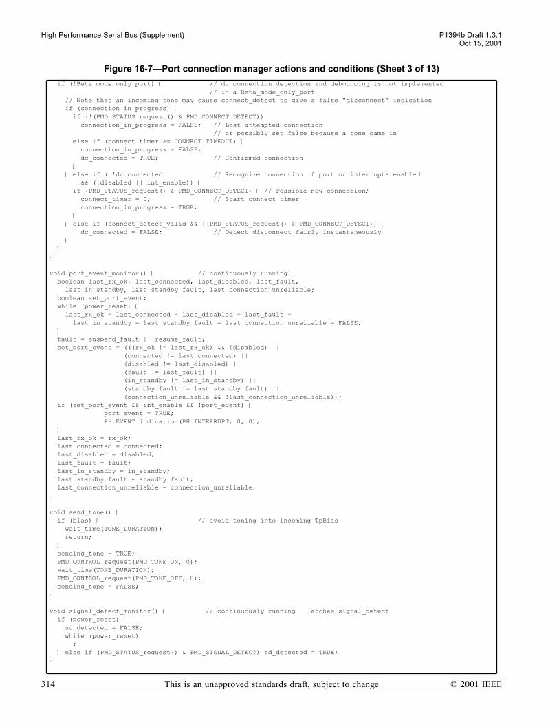
High Performance Serial Bus (Supplement) P1394b Draft 1.3.1Oct 15, 2001
if (!Beta_mode_only_port) // dc connection detection and debouncing is not implemented // in a Beta_mode_only_port // Note that an incoming tone may cause connect_detect to give a false disconnect indication if (connection_in_progress) if (!(PMD_STATUS_request() & PMD_CONNECT_DETECT)) connection_in_progress = FALSE; // Lost attempted connection // or possibly set false because a tone came in else if (connect_timer >= CONNECT_TIMEOUT) connection_in_progress = FALSE; dc_connected = TRUE; // Confirmed connection else if ( !dc_connected // Recognize connection if port or interrupts enabled && (!disabled || int_enable)) if (PMD_STATUS_request() & PMD_CONNECT_DETECT) // Possible new connection? connect_timer = 0; // Start connect timer connection_in_progress = TRUE; else if (connect_detect_valid && !(PMD_STATUS_request() & PMD_CONNECT_DETECT)) dc_connected = FALSE; // Detect disconnect fairly instantaneously
void port_event_monitor() // continuously running boolean last_rx_ok, last_connected, last_disabled, last_fault, last_in_standby, last_standby_fault, last_connection_unreliable; boolean set_port_event; while (power_reset) last_rx_ok = last_connected = last_disabled = last_fault = last_in_standby = last_standby_fault = last_connection_unreliable = FALSE; fault = suspend_fault || resume_fault; set_port_event = (((rx_ok != last_rx_ok) && !disabled) || (connected != last_connected) || (disabled != last_disabled) || (fault != last_fault) || (in_standby != last_in_standby) || (standby_fault != last_standby_fault) || (connection_unreliable && !last_connection_unreliable)); if (set_port_event && int_enable && !port_event) port_event = TRUE; PH_EVENT_indication(PH_INTERRUPT, 0, 0); last_rx_ok = rx_ok; last_connected = connected; last_disabled = disabled; last_fault = fault; last_in_standby = in_standby; last_standby_fault = standby_fault; last_connection_unreliable = connection_unreliable;
void send_tone() if (bias) // avoid toning into incoming TpBias wait_time(TONE_DURATION); return; sending_tone = TRUE; PMD_CONTROL_request(PMD_TONE_ON, 0); wait_time(TONE_DURATION); PMD_CONTROL_request(PMD_TONE_OFF, 0); sending_tone = FALSE;
void signal_detect_monitor() // continuously running - latches signal_detect if (power_reset) sd_detected = FALSE; while (power_reset) ; else if (PMD_STATUS_request() & PMD_SIGNAL_DETECT) sd_detected = TRUE;
Figure 16-7Port connection manager actions and conditions (Sheet 3 of 13)
314 This is an unapproved standards draft, subject to change © 2001 IEEE
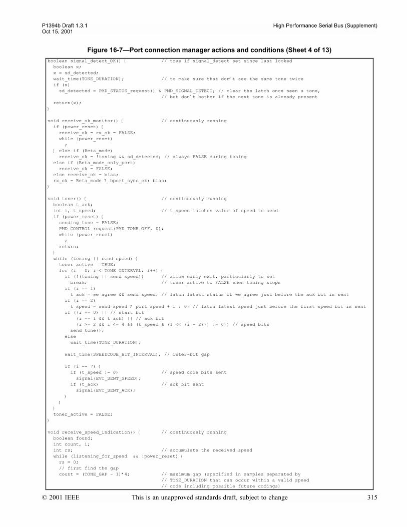
P1394b Draft 1.3.1 High Performance Serial Bus (Supplement)Oct 15, 2001
boolean signal_detect_OK() // true if signal_detect set since last looked boolean x; x = sd_detected; wait_time(TONE_DURATION); // to make sure that dont see the same tone twice if (x) sd_detected = PMD_STATUS_request() & PMD_SIGNAL_DETECT; // clear the latch once seen a tone, // but dont bother if the next tone is already present return(x);
void receive_ok_monitor() // continuously running if (power_reset) receive_ok = rx_ok = FALSE; while (power_reset) ; else if (Beta_mode) receive_ok = !toning && sd_detected; // always FALSE during toning else if (Beta_mode_only_port) receive_ok = FALSE; else receive_ok = bias; rx_ok = Beta_mode ? bport_sync_ok: bias;
void toner() // continuously running boolean t_ack; int i, t_speed; // t_speed latches value of speed to send if (power_reset) sending_tone = FALSE; PMD_CONTROL_request(PMD_TONE_OFF, 0); while (power_reset) ; return; while (toning || send_speed) toner_active = TRUE; for (i = 0; i < TONE_INTERVAL; i++) if (!(toning || send_speed)) // allow early exit, particularly to set break; // toner_active to FALSE when toning stops if (i == 1) t_ack = we_agree && send_speed; // latch latest status of we_agree just before the ack bit is sent if (i == 2) t_speed = send_speed ? port_speed + 1 : 0; // latch latest speed just before the first speed bit is sent if ((i == 0) || // start bit (i == 1 && t_ack) || // ack bit (i >= 2 && i <= 4 && (t_speed & (1 << (i - 2))) != 0)) // speed bits send_tone(); else wait_time(TONE_DURATION);
wait_time(SPEEDCODE_BIT_INTERVAL); // inter-bit gap
if (i == 7) if (t_speed != 0) // speed code bits sent signal(EVT_SENT_SPEED); if (t_ack) // ack bit sent signal(EVT_SENT_ACK); toner_active = FALSE;
void receive_speed_indication() // continuously running boolean found; int count, i; int rs; // accumulate the received speed while (listening_for_speed && !power_reset) rs = 0; // first find the gap count = (TONE_GAP - 1)*4; // maximum gap (specified in samples separated by // TONE_DURATION that can occur within a valid speed // code including possible future codings)
Figure 16-7Port connection manager actions and conditions (Sheet 4 of 13)
© 2001 IEEE This is an unapproved standards draft, subject to change 315
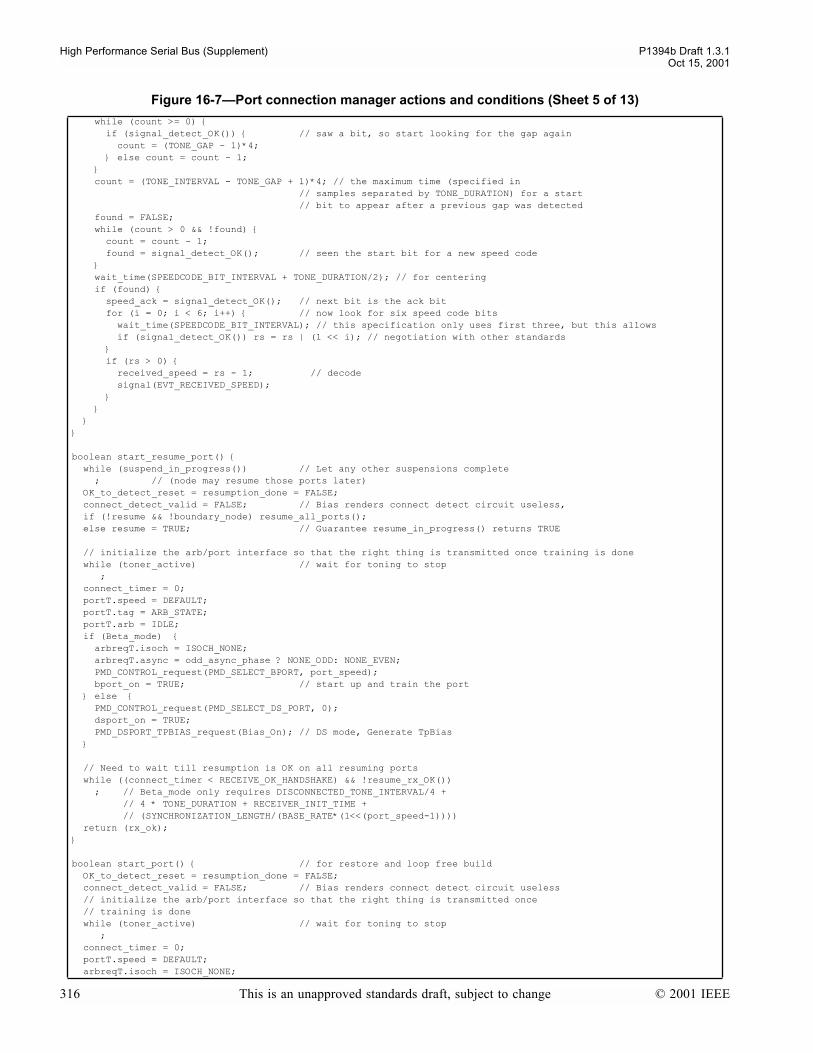
High Performance Serial Bus (Supplement) P1394b Draft 1.3.1Oct 15, 2001
while (count >= 0) if (signal_detect_OK()) // saw a bit, so start looking for the gap again count = (TONE_GAP - 1)*4; else count = count - 1; count = (TONE_INTERVAL - TONE_GAP + 1)*4; // the maximum time (specified in // samples separated by TONE_DURATION) for a start // bit to appear after a previous gap was detected found = FALSE; while (count > 0 && !found) count = count - 1; found = signal_detect_OK(); // seen the start bit for a new speed code wait_time(SPEEDCODE_BIT_INTERVAL + TONE_DURATION/2); // for centering if (found) speed_ack = signal_detect_OK(); // next bit is the ack bit for (i = 0; i < 6; i++) // now look for six speed code bits wait_time(SPEEDCODE_BIT_INTERVAL); // this specification only uses first three, but this allows if (signal_detect_OK()) rs = rs | (1 << i); // negotiation with other standards if (rs > 0) received_speed = rs - 1; // decode signal(EVT_RECEIVED_SPEED);
boolean start_resume_port() while (suspend_in_progress()) // Let any other suspensions complete ; // (node may resume those ports later) OK_to_detect_reset = resumption_done = FALSE; connect_detect_valid = FALSE; // Bias renders connect detect circuit useless, if (!resume && !boundary_node) resume_all_ports(); else resume = TRUE; // Guarantee resume_in_progress() returns TRUE
// initialize the arb/port interface so that the right thing is transmitted once training is done while (toner_active) // wait for toning to stop ; connect_timer = 0; portT.speed = DEFAULT; portT.tag = ARB_STATE; portT.arb = IDLE; if (Beta_mode) arbreqT.isoch = ISOCH_NONE; arbreqT.async = odd_async_phase ? NONE_ODD: NONE_EVEN; PMD_CONTROL_request(PMD_SELECT_BPORT, port_speed); bport_on = TRUE; // start up and train the port else PMD_CONTROL_request(PMD_SELECT_DS_PORT, 0); dsport_on = TRUE; PMD_DSPORT_TPBIAS_request(Bias_On); // DS mode, Generate TpBias
// Need to wait till resumption is OK on all resuming ports while ((connect_timer < RECEIVE_OK_HANDSHAKE) && !resume_rx_OK()) ; // Beta_mode only requires DISCONNECTED_TONE_INTERVAL/4 + // 4 * TONE_DURATION + RECEIVER_INIT_TIME + // (SYNCHRONIZATION_LENGTH/(BASE_RATE*(1<<(port_speed-1)))) return (rx_ok);
boolean start_port() // for restore and loop free build OK_to_detect_reset = resumption_done = FALSE; connect_detect_valid = FALSE; // Bias renders connect detect circuit useless // initialize the arb/port interface so that the right thing is transmitted once // training is done while (toner_active) // wait for toning to stop ; connect_timer = 0; portT.speed = DEFAULT; arbreqT.isoch = ISOCH_NONE;
Figure 16-7Port connection manager actions and conditions (Sheet 5 of 13)
316 This is an unapproved standards draft, subject to change © 2001 IEEE
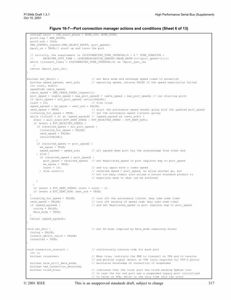
P1394b Draft 1.3.1 High Performance Serial Bus (Supplement)Oct 15, 2001
arbreqT.async = odd_async_phase ? NONE_ODD: NONE_EVEN; portT.tag = ARB_STATE; portT.arb = IDLE; PMD_CONTROL_request(PMD_SELECT_BPORT, port_speed); bport_on = TRUE;// start up and train the port
// strictly, the requirement is (DISCONNECTED_TONE_INTERVAL/4 + 4 * TONE_DURATION + // RECEIVER_INIT_TIME + (SYNCHRONIZATION_LENGTH/(BASE_RATE*(1<<(port_speed-1))))) while ((connect_timer < DISCONNECTED_TONE_INTERVAL/2) && !bport_sync_ok) ; return (bport_sync_ok);
boolean set_Beta() // set Beta mode and exchange speed codes to establish boolean speed_agreed, sent_ack; // operating speed, returns FALSE if the speed negotiation failed int count, event; speedCode cable_speed; cable_speed = PMD_CABLE_SPEED_request(); port_speed = (cable_speed < max_port_speed) ? cable_speed : max_port_speed; // our starting point if (port_speed < min_port_speed) return(FALSE); count = 10; // five tries speed_agreed = we_agree = sent_ack = FALSE; send_speed = TRUE; // start the autonomous speed sender going with the updated port_speed listening_for_speed = TRUE; // set the autonomous speed listener going; while (((count > 0) && !speed_agreed) || (speed_agreed && !sent_ack)) event = wait_event(EVT_SENT_SPEED | EVT_RECEIVED_SPEED | EVT_SENT_ACK); if (event & EVT_RECEIVED_SPEED) if (received_speed < min_port_speed) listening_for_speed = FALSE; send_speed = FALSE; return(FALSE); if (received_speed == port_speed) we_agree = TRUE; speed_agreed = speed_ack; // all agreed when port has the acknowledge from other end else if (received_speed < port_speed) port_speed = received_speed; // set Negotiated_speed in port register map to port_speed we_agree = TRUE; count = 10; // and try again with a lower speed else count++; // received speed > port_speed, so allow another go, but // not too many times; also allows a future standard product to // negotiate down to what can be achieved if (event & EVT_SENT_SPEED) count = count - 2; if (event & EVT_SENT_ACK) sent_ack = TRUE; listening_for_speed = FALSE; // turn off the autonomous listner (may take some time) send_speed = FALSE; // turn off sending of speed code (may take some time) if (speed_agreed) // and set Negotiated_speed in port register map to port_speed toning = FALSE; Beta_mode = TRUE; return (speed_agreed);
void set_DS() // set DS mode (implied by Beta_mode remaining false) toning = FALSE; connect_detect_valid = FALSE; connected = TRUE;
void connection_status() // continuously running code for each port int i; boolean crossover; // When true, instructs the PMD to transmit on TPA and to receive // and perform signal detect on TPB (only required for UTP-5 ports) boolean know_still_Beta_mode; // maintains knowledge of connection if suspended boolean new_connection_detected; boolean tried_bias; // indicates that the local port has tried sending TpBias just // in case the far end port was a suspended Legacy port initialized // to false on POR, which is the only time this can occur
Figure 16-7Port connection manager actions and conditions (Sheet 6 of 13)
© 2001 IEEE This is an unapproved standards draft, subject to change 317
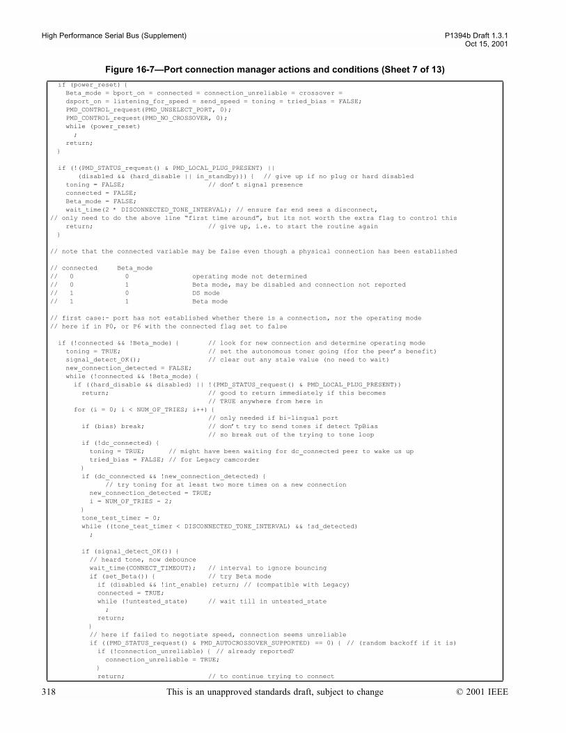
High Performance Serial Bus (Supplement) P1394b Draft 1.3.1Oct 15, 2001
if (power_reset) Beta_mode = bport_on = connected = connection_unreliable = crossover = dsport_on = listening_for_speed = send_speed = toning = tried_bias = FALSE; PMD_CONTROL_request(PMD_UNSELECT_PORT, 0); PMD_CONTROL_request(PMD_NO_CROSSOVER, 0); while (power_reset) ; return;
if (!(PMD_STATUS_request() & PMD_LOCAL_PLUG_PRESENT) || (disabled && (hard_disable || in_standby))) // give up if no plug or hard disabled toning = FALSE; // dont signal presence connected = FALSE; Beta_mode = FALSE; wait_time(2 * DISCONNECTED_TONE_INTERVAL); // ensure far end sees a disconnect, // only need to do the above line first time around, but its not worth the extra flag to control this return; // give up, i.e. to start the routine again
// note that the connected variable may be false even though a physical connection has been established
// connected Beta_mode// 0 0 operating mode not determined// 0 1 Beta mode, may be disabled and connection not reported// 1 0 DS mode// 1 1 Beta mode
// first case:- port has not established whether there is a connection, nor the operating mode// here if in P0, or P6 with the connected flag set to false
if (!connected && !Beta_mode) // look for new connection and determine operating mode toning = TRUE; // set the autonomous toner going (for the peers benefit) signal_detect_OK(); // clear out any stale value (no need to wait) new_connection_detected = FALSE; while (!connected && !Beta_mode) if ((hard_disable && disabled) || !(PMD_STATUS_request() & PMD_LOCAL_PLUG_PRESENT)) return; // good to return immediately if this becomes // TRUE anywhere from here in for (i = 0; i < NUM_OF_TRIES; i++) // only needed if bi-lingual port if (bias) break; // dont try to send tones if detect TpBias // so break out of the trying to tone loop if (!dc_connected) toning = TRUE; // might have been waiting for dc_connected peer to wake us up tried_bias = FALSE; // for Legacy camcorder if (dc_connected && !new_connection_detected) // try toning for at least two more times on a new connection new_connection_detected = TRUE; i = NUM_OF_TRIES - 2; tone_test_timer = 0; while ((tone_test_timer < DISCONNECTED_TONE_INTERVAL) && !sd_detected) ;
if (signal_detect_OK()) // heard tone, now debounce wait_time(CONNECT_TIMEOUT); // interval to ignore bouncing if (set_Beta()) // try Beta mode if (disabled && !int_enable) return; // (compatible with Legacy) connected = TRUE; while (!untested_state) // wait till in untested_state ; return; // here if failed to negotiate speed, connection seems unreliable if ((PMD_STATUS_request() & PMD_AUTOCROSSOVER_SUPPORTED) == 0) // (random backoff if it is) if (!connection_unreliable) // already reported? connection_unreliable = TRUE; return; // to continue trying to connect
Figure 16-7Port connection manager actions and conditions (Sheet 7 of 13)
318 This is an unapproved standards draft, subject to change © 2001 IEEE

P1394b Draft 1.3.1 High Performance Serial Bus (Supplement)Oct 15, 2001
// here if failed to hear a tone if (((PMD_STATUS_request() & PMD_AUTOCROSSOVER_SUPPORTED) != 0) && !dc_connected) if (random_bool()) // try a crossover at random while (sending_tone) // but delay if sending tone ; if (!sd_detected) // final check just in case dont need to crossover = !crossover; PMD_CONTROL_request(crossover ? PMD_CROSSOVER : PMD_NO_CROSSOVER, 0); // note that the time to do signal_detect_OK means that the listening loop // is guaranteed to be longer than the toning loop on the peer connection // end of trying to tone loop// here if (1) tried toning 4 times without detecting a tone;// (2) detected a connection and tried toning twice without detecting a tone;// (3) detected incoming TpBias if (dc_connected) toning = FALSE; if (bias) bias_delay_timer = 0; while ((bias_delay_timer < 16*RESET_DETECT) && bias) ; // longer than a port operating in Legacy or Beta mode will generate it if (bias) // incoming TpBias persists set_DS(); // peer is a 1394-1995 port return; tried_bias = FALSE; // necessary to try bias after seeing bias, // as the peer port may be a Legacy port which was resuming // and then went into suspend with a resume fault, toning = TRUE; // now need to try toning again in case node/port // powered up just when a peer bilingual port was generating bias else if (!tried_bias) // Bias not present // try sending Bias just once, in case port has just powered up // whilst the connected Legacy PHY was in suspend tried_bias = TRUE; while (sending_tone) // but delay if sending tone ; connect_detect_valid = FALSE; PMD_DSPORT_TPBIAS_request(Bias_On); bias_delay_timer = 0; while ((bias_delay_timer < 12*RESET_DETECT) && !bias) ; if (bias) set_DS(); return; activate_connect_detect(0); // includes taking TpBias away // the DC connected peer port is disabled // or powered off, either way itll wake us // end of trying bias // end of DC connected actions when toning has failed or bias detected // main loop whilst not connected return; // end of look for new connection and determine operating mode
// here if connected, or Beta mode
// check for continuous signaling or bias in relevant port states if (port_state == P1 || port_state == P2 || port_state == P3 || port_state == P4 || port_state == P7 || port_state == P8 || port_state == P10 || port_state == P11) if (Beta_mode) // turn on toning if going into a suspend-type state if (!rx_ok && !((port_state == P1) || (port_state == P10) || (port_state == P11))) toning = TRUE; // turn on toning as soon as possible if (force_disconnect) // caused by failure to startup while in P10 or if a Legacy loop is detected activate_connect_detect(0); connected = force_disconnect = FALSE;
Figure 16-7Port connection manager actions and conditions (Sheet 8 of 13)
© 2001 IEEE This is an unapproved standards draft, subject to change 319

High Performance Serial Bus (Supplement) P1394b Draft 1.3.1Oct 15, 2001
wait_time(2 * DISCONNECTED_TONE_INTERVAL); // ensure the far end sees a disconnection return;
// here if P5, P6, P9 or P12 and connectivity established// look for disconnect or report bias/continuous tone if (Beta_mode) // Beta mode - send a tone at periodic intervals know_still_Beta_mode = FALSE; toning = TRUE; // turn on the autonomous toner signal_detect_OK(); // flush any stale values (no need to wait) for (i = 0; i < RESUME_CHECKS; i++) if (signal_detect_OK()) if (port_state == P1 || port_state == P10 || port_state == P11) toning = FALSE; // port changed state, so stop toning return; // this will also turn on receive_OK else know_still_Beta_mode = TRUE; if (signal_detect_OK()) // still true - continuous tone if (!disabled) // in P5:suspended state toning = FALSE; // turn off the autonomous toner return; break; // connected, but no continuous tone // loss of sync in suspend forces disconnection, so reset Beta_mode as well Beta_mode = know_still_Beta_mode && connected; if (!Beta_mode) // new disconnection when in Beta mode connected = FALSE; toning = FALSE; // ensure the far end sees a disconnection wait_time(2 * DISCONNECTED_TONE_INTERVAL); else // DS mode if (!disabled) // in P5:suspended state if (receive_ok) return; connected = dc_connected; // see if still connected
void disabled_actions() if (disable_request) disable_request = signaled = FALSE; disabled = TRUE; activate_connect_detect(0); // Enable the connect detect circuit if (in_standby) // entered here from standby while (connected) // wait for background processing to succeed in forcing a disconnect ; in_standby = FALSE;
void resume_actions() if (start_resume_port()) restore_port(); // restore port on nephew while (restore_in_progress) ; // ok to continue with resume if receive_ok is present in DS ports, // but for Beta ports bport_sync_ok should also be set if (watchdog && !port_event) port_event = TRUE; PH_EVENT_indication(PH_INTERRUPT, 0, 0);
while (rx_ok && !resumption_done) // Defer bus reset until ready if (bus_initialize_active) // Do nothing if reset commences ; else if ((Beta_mode || (connect_timer >= PORT_ENABLE_TIME)) && !OK_to_detect_reset) OK_to_detect_reset = TRUE; // Now safe to detect reset on all resuming ports
Figure 16-7Port connection manager actions and conditions (Sheet 9 of 13)
320 This is an unapproved standards draft, subject to change © 2001 IEEE
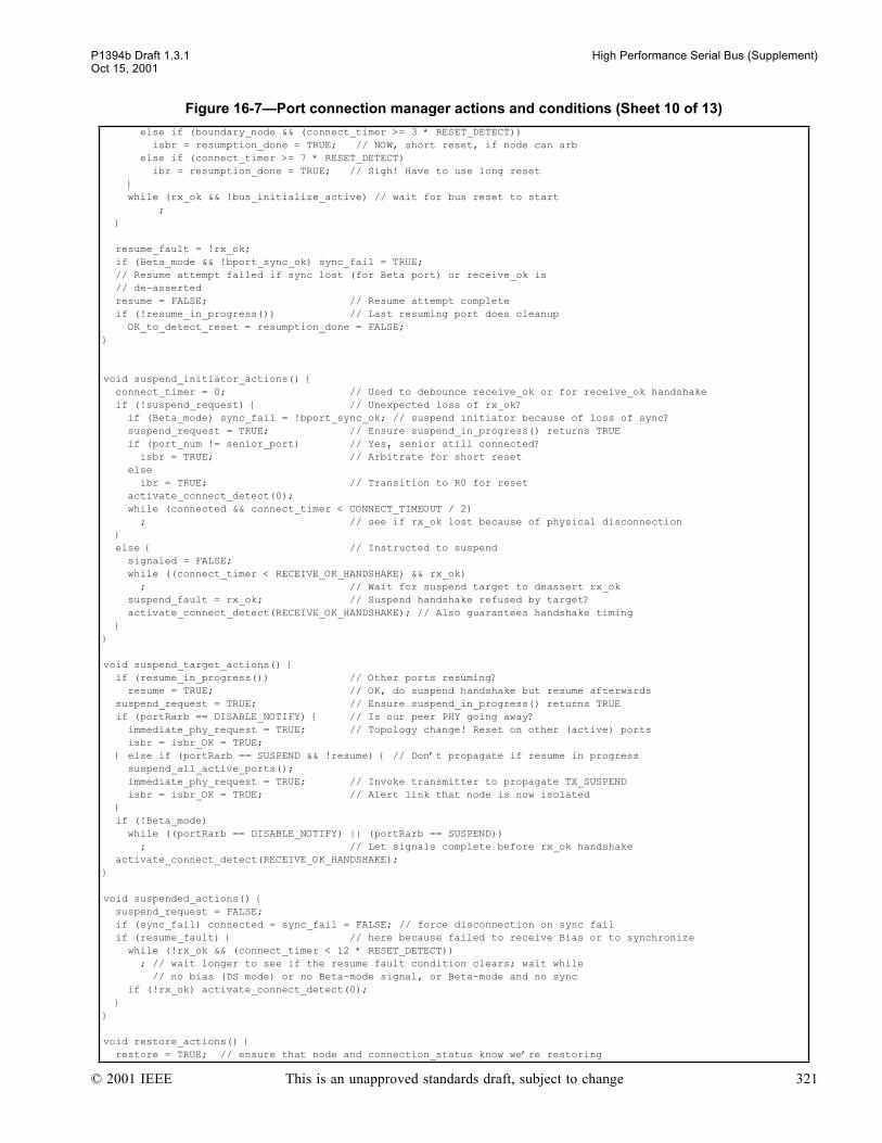
P1394b Draft 1.3.1 High Performance Serial Bus (Supplement)Oct 15, 2001
else if (boundary_node && (connect_timer >= 3 * RESET_DETECT)) isbr = resumption_done = TRUE; // NOW, short reset, if node can arb else if (connect_timer >= 7 * RESET_DETECT) ibr = resumption_done = TRUE; // Sigh! Have to use long reset while (rx_ok && !bus_initialize_active) // wait for bus reset to start ;
resume_fault = !rx_ok; if (Beta_mode && !bport_sync_ok) sync_fail = TRUE; // Resume attempt failed if sync lost (for Beta port) or receive_ok is // de-asserted resume = FALSE; // Resume attempt complete if (!resume_in_progress()) // Last resuming port does cleanup OK_to_detect_reset = resumption_done = FALSE;
void suspend_initiator_actions() connect_timer = 0; // Used to debounce receive_ok or for receive_ok handshake if (!suspend_request) // Unexpected loss of rx_ok? if (Beta_mode) sync_fail = !bport_sync_ok; // suspend initiator because of loss of sync? suspend_request = TRUE; // Ensure suspend_in_progress() returns TRUE if (port_num != senior_port) // Yes, senior still connected? isbr = TRUE; // Arbitrate for short reset else ibr = TRUE; // Transition to R0 for reset activate_connect_detect(0); while (connected && connect_timer < CONNECT_TIMEOUT / 2) ; // see if rx_ok lost because of physical disconnection else // Instructed to suspend signaled = FALSE; while ((connect_timer < RECEIVE_OK_HANDSHAKE) && rx_ok) ; // Wait for suspend target to deassert rx_ok suspend_fault = rx_ok; // Suspend handshake refused by target? activate_connect_detect(RECEIVE_OK_HANDSHAKE); // Also guarantees handshake timing
void suspend_target_actions() if (resume_in_progress()) // Other ports resuming? resume = TRUE; // OK, do suspend handshake but resume afterwards suspend_request = TRUE; // Ensure suspend_in_progress() returns TRUE if (portRarb == DISABLE_NOTIFY) // Is our peer PHY going away? immediate_phy_request = TRUE; // Topology change! Reset on other (active) ports isbr = isbr_OK = TRUE; else if (portRarb == SUSPEND && !resume) // Dont propagate if resume in progress suspend_all_active_ports(); immediate_phy_request = TRUE; // Invoke transmitter to propagate TX_SUSPEND isbr = isbr_OK = TRUE; // Alert link that node is now isolated if (!Beta_mode) while ((portRarb == DISABLE_NOTIFY) || (portRarb == SUSPEND)) ; // Let signals complete before rx_ok handshake activate_connect_detect(RECEIVE_OK_HANDSHAKE);
void suspended_actions() suspend_request = FALSE; if (sync_fail) connected = sync_fail = FALSE; // force disconnection on sync fail if (resume_fault) // here because failed to receive Bias or to synchronize while (!rx_ok && (connect_timer < 12 * RESET_DETECT)) ; // wait longer to see if the resume fault condition clears; wait while // no bias (DS mode) or no Beta-mode signal, or Beta-mode and no sync if (!rx_ok) activate_connect_detect(0);
void restore_actions() restore = TRUE; // ensure that node and connection_status know were restoring
Figure 16-7Port connection manager actions and conditions (Sheet 10 of 13)
© 2001 IEEE This is an unapproved standards draft, subject to change 321

High Performance Serial Bus (Supplement) P1394b Draft 1.3.1Oct 15, 2001
if (!proxy) // Inform nephew link immediately when a restore begins PH_EVENT_indication(PH_RESTORE_NO_RESET, 0, 0); waitPH_EVENT_response(); cancel_requests(); if (!start_port()) // Resume attempt failed if failed to synchronize restore = FALSE; force_disconnect = TRUE; while (connected) ; if (proxy) isbr = TRUE; // bus reset on disconnection, arbitrated for uncle, else ibr = TRUE; // immediate for nephew proxy = FALSE; // uncle no longer proxies for nephew return; // restore attempt failed restore_request = TRUE; // arbitrate for the bus if (!proxy) immediate_restore_request = TRUE; // on nephew while (restore) // node level action clears this ; // Connection restored to active state if (watchdog && !port_event) port_event = TRUE; PH_EVENT_indication(PH_INTERRUPT, 0, 0); in_standby = FALSE;
void standby_initiator_actions() in_standby = TRUE; // for the purpose of port status accounting connect_timer = 0; // Used to debounce rx_ok or for rx_ok handshake signaled = FALSE; while ((connect_timer < RECEIVE_OK_HANDSHAKE) && rx_ok) ; // Wait for suspend target to deassert rx_ok standby_fault = rx_ok; // Standby handshake refused by target? activate_connect_detect(RECEIVE_OK_HANDSHAKE); // Also guarantees handshake timing
void standby_target_actions() in_standby = TRUE; // for the purpose of port status accounting proxy = TRUE; // tell the arb state machine to proxy for this port activate_connect_detect(RECEIVE_OK_HANDSHAKE);
void standby_actions() do_standby = FALSE; reset_notify = FALSE; // gone into standby since the last reset (note, now a per-port bit) while (!((restore || (!standby_fault && receive_ok)) || // exit condition to restore disabled)) // exit condition to disabled if (!connected) if (proxy) isbr = TRUE; // bus reset on disconnection, arbitrated for uncle, else ibr = TRUE; // immediate for nephew break;
void untested_actions() untested_state = TRUE; if (!force_disconnect && start_port()) // port is currently sending _NONE arb requests
if (all_ports_suspended) // new connection on a suspended node resume_all_ports(); while (resume_in_progress()) ;
// the following needs to be done if this is a new connection restore_port(); // if not a proxying port, then restore the standby while (restore_in_progress()) // port first (if any) and wait for it to restore ; if (NPORT==1)
Figure 16-7Port connection manager actions and conditions (Sheet 11 of 13)
322 This is an unapproved standards draft, subject to change © 2001 IEEE

P1394b Draft 1.3.1 High Performance Serial Bus (Supplement)Oct 15, 2001
portT.arb = ATTACH_REQUEST; // single port PHYs can blindly request an attach portT.speed = DEFAULT; portT.tag = ARB_STATE; while (bport_sync_ok && !attach) if (bus_initialize_active) // Dont allow attach to start in the middle of an existing reset ; else if ((portRarb == BUS_RESET) || (portRarb == ATTACH_REQUEST)) isbr = attach = TRUE; // Peer port initiated, arm reset_detected and attempt a short reset while (bport_sync_ok && !bus_initialize_active) // wait for bus reset to start ; else // not a single port phy portT.arb = SPEED; // start LTS with normal packet start at the port speed portT.speed = DEFAULT; portT.pkt = BETA; portT.tag = ARB_STATE; wait_symbol_time(port_speed); // send speed signal (single SPEEDb) portT.arb = DATA_PREFIX; wait_symbol_time(port_speed); // send DATA_PREFIX if (border_node) // strictly the following test is required to remain true until tree_ID completes on all Legacy ports while (bus_initialize_active) ; portT.data = HR_mode << 7 | HR_G << 6 | HR_test_value; // Loop test symbol portT.tag = DATA; // send the LTS continuously
// now make sure that this wont create a bus topology loop while (bport_sync_ok && !((portRarb == DATA_BYTE) || (portRarb == ATTACH_REQUEST))) ; // wait for LTS coming in (ignoring the DP which will precede it and set in-packet context) or // the ATTACH_REQUEST which can be immediately sent by a single-port PHY untested = bport_sync_ok; // Mark port as ready for testing while (bport_sync_ok && untested && !(port_under_test && found_loop)) if (port_under_test && send_attach) // second phase - attach the port then activate it portT.arb = ATTACH_REQUEST; // note, can only get here if in control of the bus portT.speed = DEFAULT; portT.tag = ARB_STATE;
// wait for reset, attach_request, or timer to expire
if (isolated_node) attach = TRUE; // release bus and prepare to attach with next bus reset // Note that a bus reset is not scheduled. // Instead, wait as long as possible for reset_detected to hear an inbound reset on this port while (bport_sync_ok && !bus_initialize_active) if (portRarb == ATTACH_REQUEST) isbr = TRUE; // Peer port initiated and a short reset can be attempted if (max_occupancy_timer >= 7*RESET_DETECT) ibr = TRUE; // Peer port failed to initiate, so need to use long reset untested = FALSE; else while (bport_sync_ok && !attach) if (portRarb == BUS_RESET) isbr = attach = TRUE; // Peer port initiated, signal node controller // to release bus and attempt a short reset else if (max_occupancy_timer >= MAX_OCCUPANCY_TIME) ibr = attach = TRUE; // Peer port failed to initiate, so need to use long reset else if (ibr) attach = TRUE; // Another ports untested peer has gotten impatient // and initiated a long bus reset in order to attach, // so release the bus and use reset for attach while (bport_sync_ok && !bus_initialize_active) // wait for bus reset to start ; untested = FALSE; // as its now tested!!!
else
portT.data = HR_mode << 7 | HR_G << 6 | HR_test_value; // Loop test symbol portT.tag = DATA; // send the LTS continuously
Figure 16-7Port connection manager actions and conditions (Sheet 12 of 13)
© 2001 IEEE This is an unapproved standards draft, subject to change 323

High Performance Serial Bus (Supplement) P1394b Draft 1.3.1Oct 15, 2001
if (portRarb == ATTACH_REQUEST) // takes the port out of packet context while (bport_sync_ok && bus_initialize_active) // Defer bus reset until any ; // current reset completes if (bport_sync_ok) // If still synchronized, mark port to be attached. isbr = attach = TRUE; // Note that although a short bus reset is scheduled, // it will have no effect if the node has scheduled // an ATTACH_REQUEST of its own on another port and // has retained control of the bus (isolated nodes // are the exception). In such a case, the node // awaits an ATTACH_REQUEST, BUS_RESET, or timeout // on the test_port, or for this port to get // impatient and set the ibr flag below. while (bport_sync_ok && !bus_initialize_active) // wait for bus reset to start if (portRarb == BUS_RESET) // Peer port has gotten impatient. Signal ibr = TRUE; // port_under_test, if any, to release bus untested = FALSE; // as its now tested!!! // end of loop while untested // end of if NPORT==1 else ... statement // end of if start_port() loop_disabled = (port_under_test && found_loop); if (!bport_sync_ok) loop_disabled = TRUE; untested = FALSE; // as its now tested!!! attach = FALSE; // Attach attempt complete untested_state = FALSE; // will always take one of the transitions immediately void loop_disabled_actions() activate_connect_detect(0); while (PMD_STATUS_request() & PMD_SIGNAL_DETECT) ; // Wait til peer becomes inactive
Figure 16-7Port connection manager actions and conditions (Sheet 13 of 13)
324 This is an unapproved standards draft, subject to change © 2001 IEEE
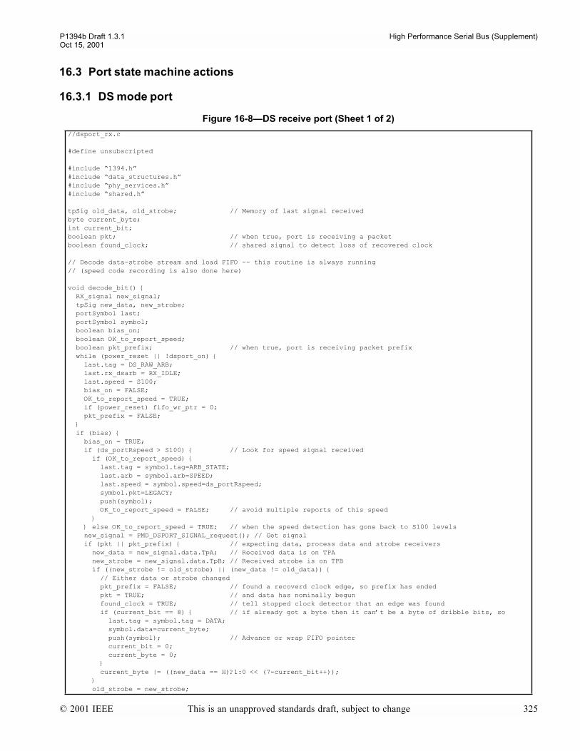
P1394b Draft 1.3.1 High Performance Serial Bus (Supplement)Oct 15, 2001
16.3 Port state machine actions
16.3.1 DS mode port
Figure 16-8DS receive port (Sheet 1 of 2)
//dsport_rx.c
#define unsubscripted
#include 1394.h#include data_structures.h#include phy_services.h#include shared.h
tpSig old_data, old_strobe; // Memory of last signal receivedbyte current_byte;int current_bit;boolean pkt; // when true, port is receiving a packetboolean found_clock; // shared signal to detect loss of recovered clock
// Decode data-strobe stream and load FIFO -- this routine is always running// (speed code recording is also done here)
void decode_bit() RX_signal new_signal; tpSig new_data, new_strobe; portSymbol last; portSymbol symbol; boolean bias_on; boolean OK_to_report_speed; boolean pkt_prefix; // when true, port is receiving packet prefix while (power_reset || !dsport_on) last.tag = DS_RAW_ARB; last.rx_dsarb = RX_IDLE; last.speed = S100; bias_on = FALSE; OK_to_report_speed = TRUE; if (power_reset) fifo_wr_ptr = 0; pkt_prefix = FALSE; if (bias) bias_on = TRUE; if (ds_portRspeed > S100) // Look for speed signal received if (OK_to_report_speed) last.tag = symbol.tag=ARB_STATE; last.arb = symbol.arb=SPEED; last.speed = symbol.speed=ds_portRspeed; symbol.pkt=LEGACY; push(symbol); OK_to_report_speed = FALSE; // avoid multiple reports of this speed else OK_to_report_speed = TRUE; // when the speed detection has gone back to S100 levels new_signal = PMD_DSPORT_SIGNAL_request(); // Get signal if (pkt || pkt_prefix) // expecting data, process data and strobe receivers new_data = new_signal.data.TpA; // Received data is on TPA new_strobe = new_signal.data.TpB; // Received strobe is on TPB if ((new_strobe != old_strobe) || (new_data != old_data)) // Either data or strobe changed pkt_prefix = FALSE; // found a recoverd clock edge, so prefix has ended pkt = TRUE; // and data has nominally begun found_clock = TRUE; // tell stopped clock detector that an edge was found if (current_bit == 8) // if already got a byte then it cant be a byte of dribble bits, so last.tag = symbol.tag = DATA; symbol.data=current_byte; push(symbol); // Advance or wrap FIFO pointer current_bit = 0; current_byte = 0; current_byte |= ((new_data == H)?1:0 << (7-current_bit++)); old_strobe = new_strobe;
© 2001 IEEE This is an unapproved standards draft, subject to change 325
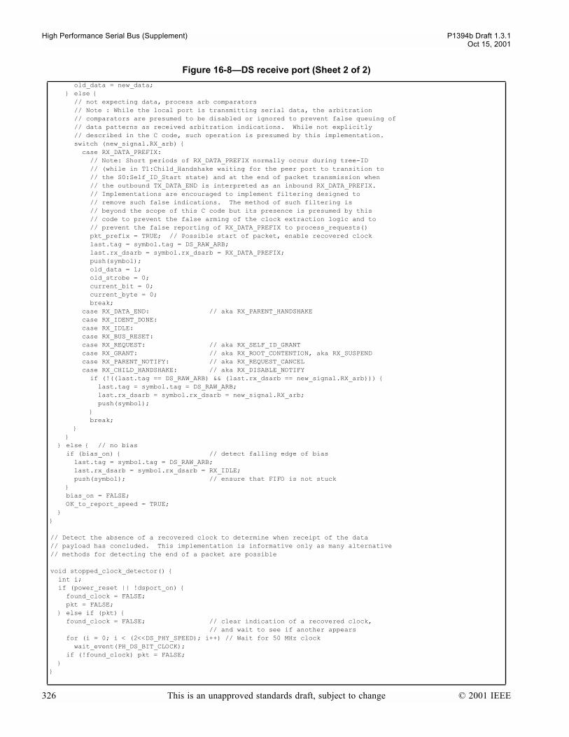
High Performance Serial Bus (Supplement) P1394b Draft 1.3.1Oct 15, 2001
old_data = new_data; else // not expecting data, process arb comparators // Note : While the local port is transmitting serial data, the arbitration // comparators are presumed to be disabled or ignored to prevent false queuing of // data patterns as received arbitration indications. While not explicitly // described in the C code, such operation is presumed by this implementation. switch (new_signal.RX_arb) case RX_DATA_PREFIX: // Note: Short periods of RX_DATA_PREFIX normally occur during tree-ID // (while in T1:Child_Handshake waiting for the peer port to transition to // the S0:Self_ID_Start state) and at the end of packet transmission when // the outbound TX_DATA_END is interpreted as an inbound RX_DATA_PREFIX. // Implementations are encouraged to implement filtering designed to // remove such false indications. The method of such filtering is // beyond the scope of this C code but its presence is presumed by this // code to prevent the false arming of the clock extraction logic and to // prevent the false reporting of RX_DATA_PREFIX to process_requests() pkt_prefix = TRUE; // Possible start of packet, enable recovered clock last.tag = symbol.tag = DS_RAW_ARB; last.rx_dsarb = symbol.rx_dsarb = RX_DATA_PREFIX; push(symbol); old_data = 1; old_strobe = 0; current_bit = 0; current_byte = 0; break; case RX_DATA_END: // aka RX_PARENT_HANDSHAKE case RX_IDENT_DONE: case RX_IDLE: case RX_BUS_RESET: case RX_REQUEST: // aka RX_SELF_ID_GRANT case RX_GRANT: // aka RX_ROOT_CONTENTION, aka RX_SUSPEND case RX_PARENT_NOTIFY: // aka RX_REQUEST_CANCEL case RX_CHILD_HANDSHAKE: // aka RX_DISABLE_NOTIFY if (!((last.tag == DS_RAW_ARB) && (last.rx_dsarb == new_signal.RX_arb))) last.tag = symbol.tag = DS_RAW_ARB; last.rx_dsarb = symbol.rx_dsarb = new_signal.RX_arb; push(symbol); break; else // no bias if (bias_on) // detect falling edge of bias last.tag = symbol.tag = DS_RAW_ARB; last.rx_dsarb = symbol.rx_dsarb = RX_IDLE; push(symbol); // ensure that FIFO is not stuck bias_on = FALSE; OK_to_report_speed = TRUE;
// Detect the absence of a recovered clock to determine when receipt of the data// payload has concluded. This implementation is informative only as many alternative// methods for detecting the end of a packet are possible
void stopped_clock_detector() int i; if (power_reset || !dsport_on) found_clock = FALSE; pkt = FALSE; else if (pkt) found_clock = FALSE; // clear indication of a recovered clock, // and wait to see if another appears for (i = 0; i < (2<<DS_PHY_SPEED); i++) // Wait for 50 MHz clock wait_event(PH_DS_BIT_CLOCK); if (!found_clock) pkt = FALSE;
Figure 16-8DS receive port (Sheet 2 of 2)
326 This is an unapproved standards draft, subject to change © 2001 IEEE
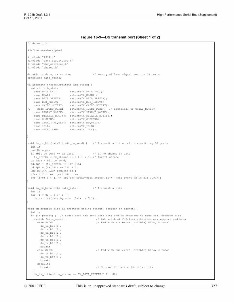
P1394b Draft 1.3.1 High Performance Serial Bus (Supplement)Oct 15, 2001
Figure 16-9DS transmit port (Sheet 1 of 2)
// dsport_tx.c
#define unsubscripted
#include 1394.h#include data_structures.h#include phy_services.h#include shared.h
dataBit tx_data, tx_strobe; // Memory of last signal sent on DS portsspeedCode data_speed;
TX_arbstate encode(ArbState arb_state) switch (arb_state) case DATA_END: return(TX_DATA_END); case GRANT: return(TX_GRANT); case DATA_PREFIX: return(TX_DATA_PREFIX); case BUS_RESET: return(TX_BUS_RESET); case CHILD_NOTIFY: return(TX_CHILD_NOTIFY);// case IDENT_DONE: return(TX_IDENT_DONE); // identical to CHILD_NOTIFY case PARENT_NOTIFY: return(TX_PARENT_NOTIFY); case DISABLE_NOTIFY: return(TX_DISABLE_NOTIFY); case SUSPEND: return(TX_SUSPEND); case LEGACY_REQUEST: return(TX_REQUEST); case IDLE: return(TX_IDLE); case SPEED_RAW: return(TX_IDLE);
void ds_tx_bit(dataBit bit_to_send) // Transmit a bit on all transmitting DS ports int i; portData pd; if (bit_to_send == tx_data) // If no change in data tx_strobe = tx_strobe == 0 ? 1 : 0; // Invert strobe tx_data = bit_to_send; pd.TpA = (tx_strobe == 1)? H:L; pd.TpB = (tx_data == 1)? H:L; PMD_DSPORT_DATA_request(pd); //wait for next port bit time for (i=0; i < (1 << (DS_PHY_SPEED-data_speed));i++) wait_event(PH_DS_BIT_CLOCK);
void ds_tx_byte(byte data_byte) // Transmit a byte int i; for (i = 0; i < 8; i++ ) ds_tx_bit((data_byte >> (7-i)) & 0b1);
void tx_dribble_bits(TX_arbstate ending_status, boolean in_packet) int i; if (in_packet) // Local port has sent data bits and is required to send real dribble bits switch (data_speed) // Bit width of PHY/link interface may require pad bits case S400: // Pad with six extra (dribble) bits, 8 total ds_tx_bit(1); ds_tx_bit(1); ds_tx_bit(1); ds_tx_bit(1); ds_tx_bit(1); ds_tx_bit(1); break; case S200: // Pad with two extra (dribble) bits, 4 total ds_tx_bit(1); ds_tx_bit(1); break; default: break; // No need for extra (dribble) bits ds_tx_bit(ending_status == TX_DATA_PREFIX ? 1 : 0);
© 2001 IEEE This is an unapproved standards draft, subject to change 327

High Performance Serial Bus (Supplement) P1394b Draft 1.3.1Oct 15, 2001
PMD_DSPORT_ARB_request(ending_status); // ...and the last dribble bit else // Local port hasnt sent any data bits, so continue DATA_PREFIX // for the dribble bit duration (equal to 2 S100 bit times) for (i=0; i < (2 << (DS_PHY_SPEED-S100));i++) wait_event(PH_DS_BIT_CLOCK); PMD_DSPORT_ARB_request(ending_status);
void dsport_transmit_actions() // continuously running boolean in_packet; // tracks whether local port has sent actual data bits while (power_reset || !dsport_on) in_packet = FALSE; data_speed = S100; if(portT.tag==DATA) in_packet = TRUE; ds_tx_byte(portT.data); else // tag == ARB_STATE switch(portT.arb) case DATA_PREFIX: case DATA_NULL: if (non_null_packet && !DS_stuck) // DP or DN at the end of a packet tx_dribble_bits(TX_DATA_PREFIX, in_packet); in_packet = FALSE; // data_speed is carried over from previous packet if not // already set by a speed signal on this packet PMD_DSPORT_TXSPEED_request(S100); // turn off speed signaling if going tx_data = 1; // Initialize the memory of last signal sent on DS ports tx_strobe = 0; PMD_DSPORT_ARB_request(TX_DATA_PREFIX); break; case SPEED: in_packet = FALSE; data_speed = portT.speed; // start tx of speed and memorize it PMD_DSPORT_ARB_request(TX_DATA_PREFIX); PMD_DSPORT_TXSPEED_request(data_speed); break; case IDENT_DONE: // control speed signal drivers directly (for self_ID) case SPEED_RAW: PMD_DSPORT_ARB_request(encode(portT.arb)); switch (portT.speed) case S100: case S200: case S400: PMD_DSPORT_TXSPEED_request(portT.speed); break; default: // ignore speed codes other than S100, S200, or S400 PMD_DSPORT_TXSPEED_request(S100); break; case DATA_END: if (non_null_packet) // add dribble bits unless a NULL packet tx_dribble_bits(TX_DATA_END, in_packet); in_packet = FALSE; data_speed = S100; // ready for next packet PMD_DSPORT_ARB_request(TX_DATA_END); break; case IDLE: case ARB_CONTEXT: in_packet = FALSE; data_speed = S100; PMD_DSPORT_ARB_request(TX_IDLE); break; default: PMD_DSPORT_ARB_request(encode(portT.arb)); break; wait_event(PH_DS_BIT_CLOCK);
Figure 16-9DS transmit port (Sheet 2 of 2)
328 This is an unapproved standards draft, subject to change © 2001 IEEE

P1394b Draft 1.3.1 High Performance Serial Bus (Supplement)Oct 15, 2001
Figure 16-10DS speed signaling filter
// speed.c
#define unsubscripted#include 1394.h#include data_structures.h#include phy_services.h#include shared.h
void speed_filter() // Continuously sample speed signals int i; boolean OK_to_sample; speedCode raw_speed[2]; // Unfiltered speed (moving window of two samples) RX_signal new_signal;
if (!bias) raw_speed[0] = S100; // initialize for (i = 0; i < (2<<DS_PHY_SPEED); i++) // Wait for 50 MHz clock wait_event(PH_DS_BIT_CLOCK); new_signal = PMD_DSPORT_SIGNAL_request(); // Get signal raw_speed[1] = raw_speed[0]; // Save prior sample if (PMD_DSPORT_RXSPEED_request() & RX_S400) // S400 observed? if (PMD_DSPORT_RXSPEED_request() & RX_S200) raw_speed[0] = S400; else if (PMD_DSPORT_RXSPEED_request() & RX_S200) // S200 observed? raw_speed[0] = S200; else raw_speed[0] = S100; // No to both: default S100 OK_to_sample = new_signal.RX_arb == RX_CHILD_HANDSHAKE // transmitting TX_IDENT_DONE || new_signal.RX_arb == RX_IDENT_DONE || new_signal.RX_arb == RX_DATA_PREFIX; if (!OK_to_sample) ds_portRspeed = S100; // Reset to S100 whenever its not OK to sample else if (raw_speed[0] == raw_speed[1]) // Consecutive identical samples? if (raw_speed[0] == S200 && ds_portRspeed < S400) ds_portRspeed = S200; // Latch S200 only if S400 not yet confirmed else if (raw_speed[0] == S400) ds_portRspeed = S400;
© 2001 IEEE This is an unapproved standards draft, subject to change 329
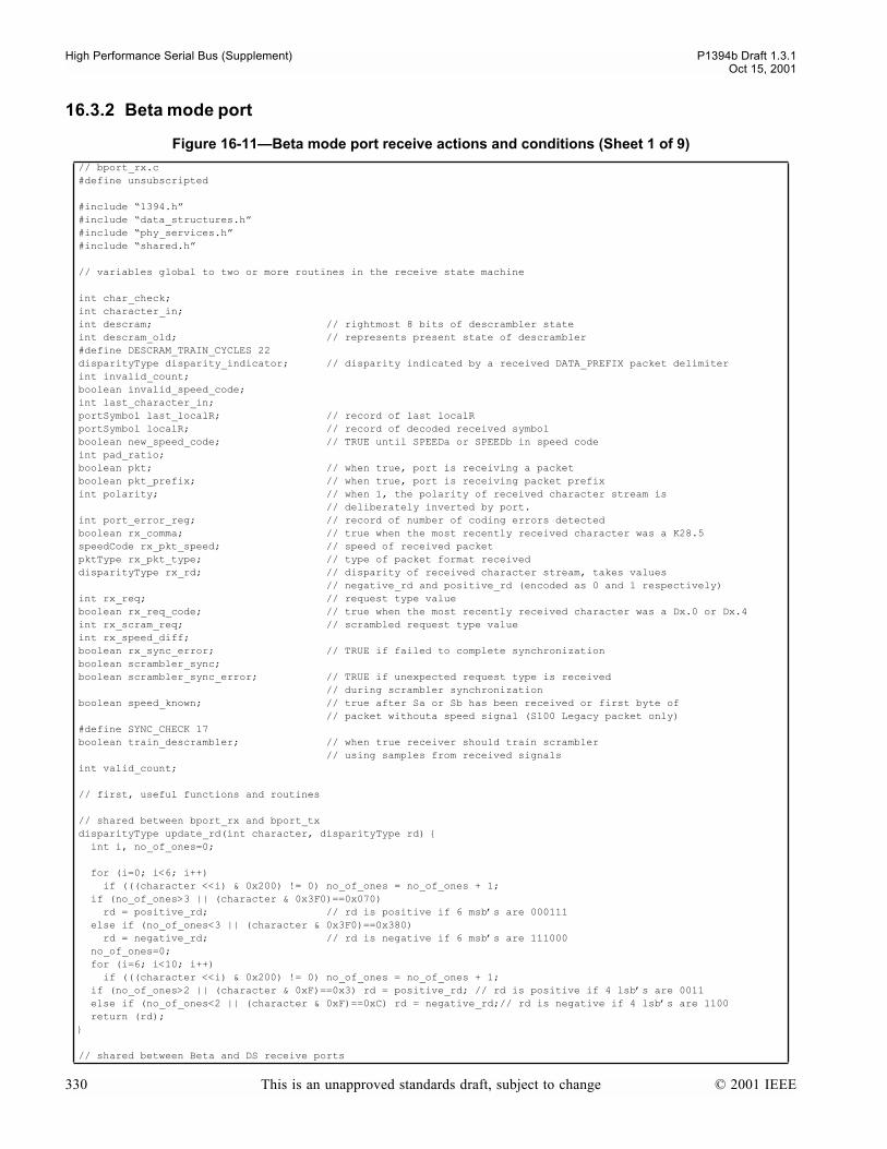
High Performance Serial Bus (Supplement) P1394b Draft 1.3.1Oct 15, 2001
16.3.2 Beta mode port
Figure 16-11Beta mode port receive actions and conditions (Sheet 1 of 9)
// bport_rx.c#define unsubscripted
#include 1394.h#include data_structures.h#include phy_services.h#include shared.h
// variables global to two or more routines in the receive state machine
int char_check;int character_in;int descram; // rightmost 8 bits of descrambler stateint descram_old; // represents present state of descrambler#define DESCRAM_TRAIN_CYCLES 22disparityType disparity_indicator; // disparity indicated by a received DATA_PREFIX packet delimiterint invalid_count;boolean invalid_speed_code;int last_character_in;portSymbol last_localR; // record of last localRportSymbol localR; // record of decoded received symbolboolean new_speed_code; // TRUE until SPEEDa or SPEEDb in speed codeint pad_ratio;boolean pkt; // when true, port is receiving a packetboolean pkt_prefix; // when true, port is receiving packet prefixint polarity; // when 1, the polarity of received character stream is // deliberately inverted by port.int port_error_reg; // record of number of coding errors detectedboolean rx_comma; // true when the most recently received character was a K28.5speedCode rx_pkt_speed; // speed of received packetpktType rx_pkt_type; // type of packet format receiveddisparityType rx_rd; // disparity of received character stream, takes values // negative_rd and positive_rd (encoded as 0 and 1 respectively)int rx_req; // request type valueboolean rx_req_code; // true when the most recently received character was a Dx.0 or Dx.4int rx_scram_req; // scrambled request type valueint rx_speed_diff;boolean rx_sync_error; // TRUE if failed to complete synchronizationboolean scrambler_sync;boolean scrambler_sync_error; // TRUE if unexpected request type is received // during scrambler synchronizationboolean speed_known; // true after Sa or Sb has been received or first byte of // packet withouta speed signal (S100 Legacy packet only)#define SYNC_CHECK 17 boolean train_descrambler; // when true receiver should train scrambler // using samples from received signalsint valid_count;
// first, useful functions and routines
// shared between bport_rx and bport_txdisparityType update_rd(int character, disparityType rd) int i, no_of_ones=0; for (i=0; i<6; i++) if (((character <<i) & 0x200) != 0) no_of_ones = no_of_ones + 1; if (no_of_ones>3 || (character & 0x3F0)==0x070) rd = positive_rd; // rd is positive if 6 msbs are 000111 else if (no_of_ones<3 || (character & 0x3F0)==0x380) rd = negative_rd; // rd is negative if 6 msbs are 111000 no_of_ones=0; for (i=6; i<10; i++) if (((character <<i) & 0x200) != 0) no_of_ones = no_of_ones + 1; if (no_of_ones>2 || (character & 0xF)==0x3) rd = positive_rd; // rd is positive if 4 lsbs are 0011 else if (no_of_ones<2 || (character & 0xF)==0xC) rd = negative_rd;// rd is negative if 4 lsbs are 1100 return (rd);
// shared between Beta and DS receive ports
330 This is an unapproved standards draft, subject to change © 2001 IEEE
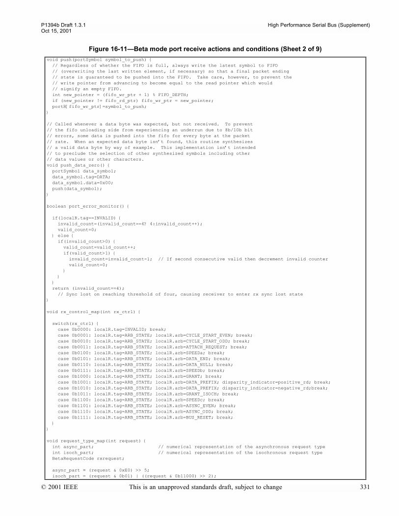
P1394b Draft 1.3.1 High Performance Serial Bus (Supplement)Oct 15, 2001
void push(portSymbol symbol_to_push) // Regardless of whether the FIFO is full, always write the latest symbol to FIFO // (overwriting the last written element, if necessary) so that a final packet ending // state is guaranteed to be pushed into the FIFO. Take care, however, to prevent the // write pointer from advancing to become equal to the read pointer which would // signify an empty FIFO. int new_pointer = (fifo_wr_ptr + 1) % FIFO_DEPTH; if (new_pointer != fifo_rd_ptr) fifo_wr_ptr = new_pointer; portR[fifo_wr_ptr]=symbol_to_push;
// Called whenever a data byte was expected, but not received. To prevent// the fifo unloading side from experiencing an underrun due to 8b/10b bit// errors, some data is pushed into the fifo for every byte at the packet// rate. When an expected data byte isnt found, this routine synthesizes// a valid data byte by way of example. This implementation isnt intended// to preclude the selection of other synthesized symbols including other// data values or other characters. void push_data_zero() portSymbol data_symbol; data_symbol.tag=DATA; data_symbol.data=0x00; push(data_symbol);
boolean port_error_monitor()
if(localR.tag==INVALID) invalid_count=(invalid_count==4? 4:invalid_count++); valid_count=0; else if(invalid_count>0) valid_count=valid_count++; if(valid_count>1) invalid_count=invalid_count-1; // If second consecutive valid then decrement invalid counter valid_count=0; return (invalid_count==4); // Sync lost on reaching threshold of four, causing receiver to enter rx sync lost state
void rx_control_map(int rx_ctrl)
switch(rx_ctrl) case 0b0000: localR.tag=INVALID; break; case 0b0001: localR.tag=ARB_STATE; localR.arb=CYCLE_START_EVEN; break; case 0b0010: localR.tag=ARB_STATE; localR.arb=CYCLE_START_ODD; break; case 0b0011: localR.tag=ARB_STATE; localR.arb=ATTACH_REQUEST; break; case 0b0100: localR.tag=ARB_STATE; localR.arb=SPEEDa; break; case 0b0101: localR.tag=ARB_STATE; localR.arb=DATA_END; break; case 0b0110: localR.tag=ARB_STATE; localR.arb=DATA_NULL; break; case 0b0111: localR.tag=ARB_STATE; localR.arb=SPEEDb; break; case 0b1000: localR.tag=ARB_STATE; localR.arb=GRANT; break; case 0b1001: localR.tag=ARB_STATE; localR.arb=DATA_PREFIX; disparity_indicator=positive_rd; break; case 0b1010: localR.tag=ARB_STATE; localR.arb=DATA_PREFIX; disparity_indicator=negative_rd;break; case 0b1011: localR.tag=ARB_STATE; localR.arb=GRANT_ISOCH; break; case 0b1100: localR.tag=ARB_STATE; localR.arb=SPEEDc; break; case 0b1101: localR.tag=ARB_STATE; localR.arb=ASYNC_EVEN; break; case 0b1110: localR.tag=ARB_STATE; localR.arb=ASYNC_ODD; break; case 0b1111: localR.tag=ARB_STATE; localR.arb=BUS_RESET; break;
void request_type_map(int request) int async_part; // numerical representation of the asynchronous request type int isoch_part; // numerical representation of the isochronous request type BetaRequestCode rxrequest; async_part = (request & 0xE0) >> 5; isoch_part = (request & 0b01) | ((request & 0b11000) >> 2);
Figure 16-11Beta mode port receive actions and conditions (Sheet 2 of 9)
© 2001 IEEE This is an unapproved standards draft, subject to change 331
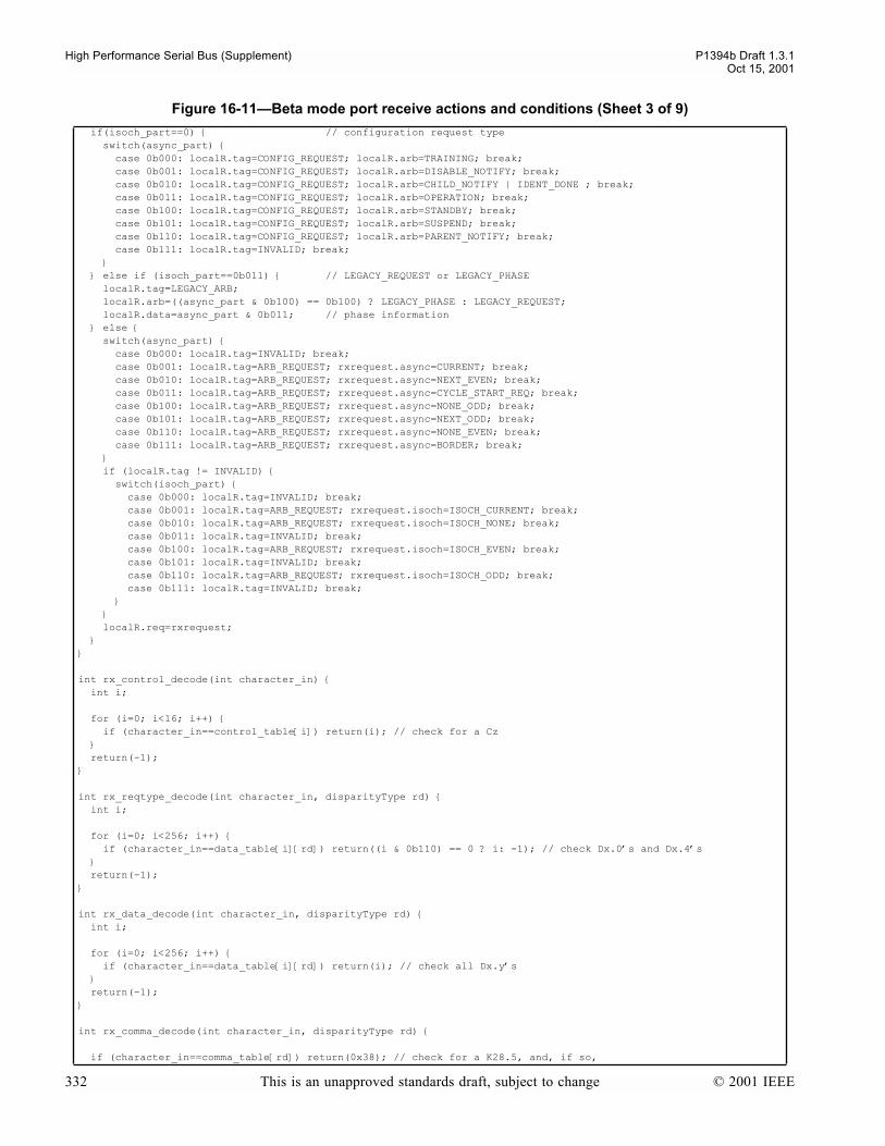
High Performance Serial Bus (Supplement) P1394b Draft 1.3.1Oct 15, 2001
if(isoch_part==0) // configuration request type switch(async_part) case 0b000: localR.tag=CONFIG_REQUEST; localR.arb=TRAINING; break; case 0b001: localR.tag=CONFIG_REQUEST; localR.arb=DISABLE_NOTIFY; break; case 0b010: localR.tag=CONFIG_REQUEST; localR.arb=CHILD_NOTIFY | IDENT_DONE ; break; case 0b011: localR.tag=CONFIG_REQUEST; localR.arb=OPERATION; break; case 0b100: localR.tag=CONFIG_REQUEST; localR.arb=STANDBY; break; case 0b101: localR.tag=CONFIG_REQUEST; localR.arb=SUSPEND; break; case 0b110: localR.tag=CONFIG_REQUEST; localR.arb=PARENT_NOTIFY; break; case 0b111: localR.tag=INVALID; break; else if (isoch_part==0b011) // LEGACY_REQUEST or LEGACY_PHASE localR.tag=LEGACY_ARB; localR.arb=((async_part & 0b100) == 0b100) ? LEGACY_PHASE : LEGACY_REQUEST; localR.data=async_part & 0b011; // phase information else switch(async_part) case 0b000: localR.tag=INVALID; break; case 0b001: localR.tag=ARB_REQUEST; rxrequest.async=CURRENT; break; case 0b010: localR.tag=ARB_REQUEST; rxrequest.async=NEXT_EVEN; break; case 0b011: localR.tag=ARB_REQUEST; rxrequest.async=CYCLE_START_REQ; break; case 0b100: localR.tag=ARB_REQUEST; rxrequest.async=NONE_ODD; break; case 0b101: localR.tag=ARB_REQUEST; rxrequest.async=NEXT_ODD; break; case 0b110: localR.tag=ARB_REQUEST; rxrequest.async=NONE_EVEN; break; case 0b111: localR.tag=ARB_REQUEST; rxrequest.async=BORDER; break; if (localR.tag != INVALID) switch(isoch_part) case 0b000: localR.tag=INVALID; break; case 0b001: localR.tag=ARB_REQUEST; rxrequest.isoch=ISOCH_CURRENT; break; case 0b010: localR.tag=ARB_REQUEST; rxrequest.isoch=ISOCH_NONE; break; case 0b011: localR.tag=INVALID; break; case 0b100: localR.tag=ARB_REQUEST; rxrequest.isoch=ISOCH_EVEN; break; case 0b101: localR.tag=INVALID; break; case 0b110: localR.tag=ARB_REQUEST; rxrequest.isoch=ISOCH_ODD; break; case 0b111: localR.tag=INVALID; break; localR.req=rxrequest;
int rx_control_decode(int character_in) int i; for (i=0; i<16; i++) if (character_in==control_table[i]) return(i); // check for a Cz return(-1);
int rx_reqtype_decode(int character_in, disparityType rd) int i; for (i=0; i<256; i++) if (character_in==data_table[i][rd]) return((i & 0b110) == 0 ? i: -1); // check Dx.0s and Dx.4s return(-1);
int rx_data_decode(int character_in, disparityType rd) int i; for (i=0; i<256; i++) if (character_in==data_table[i][rd]) return(i); // check all Dx.ys return(-1);
int rx_comma_decode(int character_in, disparityType rd)
if (character_in==comma_table[rd]) return(0x38); // check for a K28.5, and, if so,
Figure 16-11Beta mode port receive actions and conditions (Sheet 3 of 9)
332 This is an unapproved standards draft, subject to change © 2001 IEEE

P1394b Draft 1.3.1 High Performance Serial Bus (Supplement)Oct 15, 2001
// decode as if D28.0 (NB bits reversed) else return(-1);
void update_descrambler() int i; int descram_new; // next state if (train_descrambler && (rx_scram_req >= 0)) descram_old = (descram_old & 0x7FE) | (rx_scram_req & 0x001); // replacing rx_scram_req bit 0 (from the right) into descram_old when training descrambler descram_new = descram_old; for (i=0; i<8; i++) descram_new = descram_new << 1; descram_new = descram_new | (((descram_old & 0x400) >> 10) ^ ((descram_old & 0x100) >> 8)); descram_old = descram_new; descram = descram_old & 0x0FF; // used for XORing with input byte
boolean rx_character() int i; PMD_data_ind_service PMD_data; dataBit received_bit; int rx_scram_data; int rx_scram_ctrl; int rx_control; last_localR=localR; last_character_in=character_in; rx_comma=FALSE; rx_req_code=FALSE; character_in=0; for (i=0;i<10;i++) PMD_data = waitPMD_DATA_indication(); received_bit = PMD_data.data; character_in = (character_in << 1) | (received_bit ^ polarity); rx_scram_ctrl = rx_scram_req = rx_scram_data = -1; // Reset remaining result from last character if((rx_scram_ctrl=rx_control_decode(character_in))>=0) rx_control=(rx_scram_ctrl^(((descram&0x80)>>4) | ((descram&0x20)>>3) | ((descram&0x8)>>2) | ((descram&0x2)>>1))); rx_control_map(rx_control); else if(((rx_scram_req=rx_reqtype_decode(character_in,rx_rd)) >=0) && !pkt && !pkt_prefix) rx_req_code=TRUE; rx_req=(rx_scram_req ^ descram) & 0xF9; request_type_map(rx_req); else if(((rx_scram_data=rx_data_decode(character_in,rx_rd))>=0) && (pkt || pkt_prefix) ) localR.tag=DATA; localR.data=rx_scram_data ^ descram; else if(((rx_scram_req=rx_comma_decode(character_in, rx_rd))>=0) && !pkt && !pkt_prefix) rx_comma=TRUE; rx_req_code=TRUE; rx_req=(rx_scram_req ^ descram) & 0xF9; request_type_map(rx_req); else localR.tag=INVALID; update_descrambler(); if (rx_scram_ctrl < 0) rx_rd=update_rd(character_in, rx_rd); // control characters are all neutral disparity. // update_rd() should never be used for control characters. if (localR.tag == ARB_STATE && localR.arb==DATA_PREFIX) rx_rd=disparity_indicator; // rd is always reset when a data prefix symbol is received. return(port_error_monitor()); // check that synchronization is OK
Figure 16-11Beta mode port receive actions and conditions (Sheet 4 of 9)
© 2001 IEEE This is an unapproved standards draft, subject to change 333
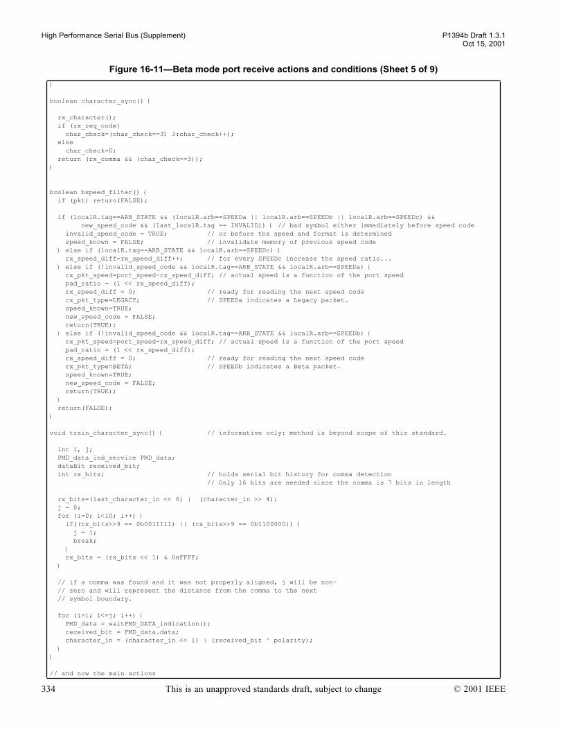
High Performance Serial Bus (Supplement) P1394b Draft 1.3.1Oct 15, 2001
boolean character_sync()
rx_character(); if (rx_req_code) char_check=(char_check==3? 3:char_check++); else char_check=0; return (rx_comma && (char_check==3));
boolean bspeed_filter() if (pkt) return(FALSE);
if (localR.tag==ARB_STATE && (localR.arb==SPEEDa || localR.arb==SPEEDb || localR.arb==SPEEDc) && new_speed_code && (last_localR.tag == INVALID)) // bad symbol either immediately before speed code invalid_speed_code = TRUE; // or before the speed and format is determined speed_known = FALSE; // invalidate memory of previous speed code else if (localR.tag==ARB_STATE && localR.arb==SPEEDc) rx_speed_diff=rx_speed_diff++; // for every SPEEDc increase the speed ratio... else if (!invalid_speed_code && localR.tag==ARB_STATE && localR.arb==SPEEDa) rx_pkt_speed=port_speed-rx_speed_diff; // actual speed is a function of the port speed pad_ratio = (1 << rx_speed_diff); rx_speed_diff = 0; // ready for reading the next speed code rx_pkt_type=LEGACY; // SPEEDa indicates a Legacy packet. speed_known=TRUE; new_speed_code = FALSE; return(TRUE); else if (!invalid_speed_code && localR.tag==ARB_STATE && localR.arb==SPEEDb) rx_pkt_speed=port_speed-rx_speed_diff; // actual speed is a function of the port speed pad_ratio = (1 << rx_speed_diff); rx_speed_diff = 0; // ready for reading the next speed code rx_pkt_type=BETA; // SPEEDb indicates a Beta packet. speed_known=TRUE; new_speed_code = FALSE; return(TRUE); return(FALSE);
void train_character_sync() // informative only: method is beyond scope of this standard.
int i, j; PMD_data_ind_service PMD_data; dataBit received_bit; int rx_bits; // holds serial bit history for comma detection // Only 16 bits are needed since the comma is 7 bits in length rx_bits=(last_character_in << 6) | (character_in >> 4); j = 0; for (i=0; i<10; i++) if((rx_bits>>9 == 0b0011111) || (rx_bits>>9 == 0b1100000)) j = i; break; rx_bits = (rx_bits << 1) & 0xFFFF; // if a comma was found and it was not properly aligned, j will be non- // zero and will represent the distance from the comma to the next // symbol boundary. for (i=1; i<=j; i++) PMD_data = waitPMD_DATA_indication(); received_bit = PMD_data.data; character_in = (character_in << 1) | (received_bit ^ polarity);
// and now the main actions
Figure 16-11Beta mode port receive actions and conditions (Sheet 5 of 9)
334 This is an unapproved standards draft, subject to change © 2001 IEEE
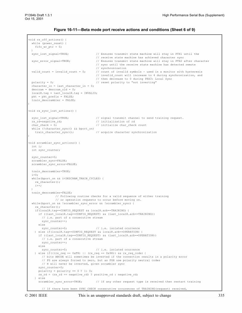
P1394b Draft 1.3.1 High Performance Serial Bus (Supplement)Oct 15, 2001
void rx_off_actions() while (power_reset) fifo_wr_ptr = 0; sync_lost_signal=TRUE; // Ensures transmit state machine will stay in PTX1 until the // receive state machine has achieved character sync sync_error_signal=TRUE; // Ensures transmit state machine will stay in PTX2 after character // sync until the receive state machine has detected remote // synchronization valid_count = invalid_count = 0; // count of invalid symbols - used in a monitor with hysteresis // invalid_count will increase to 4 during synchronization, and // then decrease to 0 during PRX3: Local Sync polarity = 0; // reset polarity to not inverting character_in = last_character_in = 0; descram = descram_old = 0; localR.tag = last_localR.tag = INVALID; pkt = pkt_prefix = FALSE; train_descrambler = FALSE;
void rx_sync_lost_actions()
sync_lost_signal=TRUE; // signal transmit channel to send training request. rx_rd=negative_rd; // initialization of rd char_check = 0; // initialize char_check count while (!character_sync() && bport_on) train_character_sync(); // acquire character synchronization
void scrambler_sync_actions() int i; int sync_counter; sync_counter=0; scrambler_sync=FALSE; scrambler_sync_error=FALSE; train_descrambler=TRUE; i=0; while(bport_on && i<DESCRAM_TRAIN_CYCLES) rx_character(); i++; train_descrambler=FALSE; // Following routine checks for a valid sequence of either training // or operation requests to occur before moving on. while(bport_on && !scrambler_sync_error && !scrambler_sync) rx_character(); if(localR.tag==CONFIG_REQUEST && localR.arb==TRAINING) if ((last_localR.tag==CONFIG_REQUEST) && (last_localR.arb==TRAINING)) // i.e. part of a consecutive stream sync_counter++; else sync_counter=0; // i.e. isolated ocurrence else if(localR.tag==CONFIG_REQUEST && localR.arb==OPERATION) if ((last_localR.tag==CONFIG_REQUEST) && (last_localR.arb==OPERATION)) // i.e. part of a consecutive stream sync_counter++; else sync_counter=0; // i.e. isolated ocurrence else if(((rx_req == 0xF8) || (rx_req == 0x98)) && rx_req_code) // bits ABCDE will sometimes be inverted if the connection results in a polarity error // FG are always forced to zero, but as FGH use polarity neutral codes // H will never be inverted, given scrambler sync sync_counter=0; polarity = polarity == 0 ? 1: 0; rx_rd = (rx_rd == negative_rd) ? positive_rd : negative_rd; else scrambler_sync_error=TRUE; // If any other request type is received then restart training // If there have been SYNC_CHECK consecutive occurences of TRAINING(request) received,
Figure 16-11Beta mode port receive actions and conditions (Sheet 6 of 9)
© 2001 IEEE This is an unapproved standards draft, subject to change 335

High Performance Serial Bus (Supplement) P1394b Draft 1.3.1Oct 15, 2001
// or if there have been SYNC_CHECK consecutive occurences of OPERATION(request) // received, then receiver is considered to be synchronized. if(sync_counter==SYNC_CHECK) scrambler_sync=TRUE; // condition for transition to rx_sync_done state. sync_counter=0;
void rx_sync_actions() int sync_counter; boolean remote_sync_lost; sync_lost_signal = FALSE; // causes transmitter to send OPERATION request and // indicates to receiver that lock has been achieved remote_sync_lost=TRUE; // receiver does not assume peer node is synchronized // until following checks are complete rx_sync_error=FALSE; // Following routine checks for a sequence of valid OPERATION request // symbols. This indicates that the connected port is also synchronized and // the check is required to occur before receiver transitions to receive state. sync_counter=0; while(bport_on && !rx_sync_error && remote_sync_lost) rx_character(); if(localR.tag==CONFIG_REQUEST && localR.arb==TRAINING) sync_counter=0; else if(localR.tag==CONFIG_REQUEST && localR.arb==OPERATION) if ((last_localR.tag==CONFIG_REQUEST) && (last_localR.arb==OPERATION)) sync_counter++; else sync_counter=0; else rx_sync_error=TRUE; if(sync_counter==SYNC_CHECK) remote_sync_lost=FALSE; // Once connected port is seen to be synchronized, allow some extra time for remote // port to receive sufficient operation requests to know local sync is done. // If remote port sends a control signal then it knows local sync is done. // At same time, local port may determine context of signals. if (bport_on && !rx_sync_error) sync_counter=0; while(bport_on && sync_counter<SYNC_CHECK && (localR.tag==CONFIG_REQUEST)) sync_counter++; rx_character(); sync_error_signal = FALSE; // This causes transmitter to resume normal operation and receiver transitions to receive state.
void bport_receive_actions() // Equivalent mostly to 1394-1995 decode_bit routine. int pad_count=0; // keeps track of padding boolean pushed_config_request = FALSE; portSymbol speed_symbol; pkt=speed_known=FALSE; new_speed_code = TRUE; invalid_speed_code = FALSE; rx_speed_diff=0; pkt_prefix=FALSE; last_localR.tag=INVALID; while(bport_on && !sync_error_signal) // rx_character() has been called at end of rx_sync_actions() // If received character completes a valid speed signal, then a packet prefix is arriving. // Speed signal is placed in fifo, and fifo update is turned on. if (bspeed_filter()) speed_symbol.tag=ARB_STATE; speed_symbol.arb=SPEED; speed_symbol.speed=rx_pkt_speed; speed_symbol.pkt=rx_pkt_type; push(speed_symbol);
Figure 16-11Beta mode port receive actions and conditions (Sheet 7 of 9)
336 This is an unapproved standards draft, subject to change © 2001 IEEE
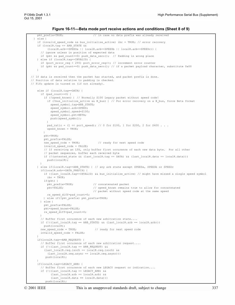
P1394b Draft 1.3.1 High Performance Serial Bus (Supplement)Oct 15, 2001
pkt_prefix=TRUE; // in case no data prefix was already received else if (invalid_speed_code && bus_initialize_active) ibr = TRUE; // error recovery if (localR.tag == ARB_STATE && (localR.arb==SPEEDa || localR.arb==SPEEDb || localR.arb==SPEEDc)) // ignore unless in position of expected data if (pkt && pad_count==0) push_data_zero(); // Padding in wrong place else if (localR.tag==INVALID) if (port_error_reg < 255) port_error_reg++; // increment error counter if (pkt && pad_count==0) push_data_zero(); // if a packet payload character, substitute 0x00 // If data is received then the packet has started, and packet prefix is done. // Position of data relative to padding is checked. // Fifo update is turned on (if not already). else if (localR.tag==DATA) if (pad_count==0) if (!speed_known) // Normally S100 Legacy packet without speed code! if (!bus_initialize_active && B_bus) // For error recovery on a B_bus, force Beta format speed_symbol.tag=ARB_STATE; speed_symbol.arb=SPEED; speed_symbol.speed=S100; speed_symbol.pkt=BETA; push(speed_symbol); pad_ratio = (1 << port_speed); // 0 for S100, 1 for S200, 2 for S400 . . . speed_known = TRUE; pkt=TRUE; pkt_prefix=FALSE; new_speed_code = TRUE; // ready for next speed code invalid_speed_code = FALSE; // If receiving an LTS, only buffer first occurence of each new data byte. For all other // packet sequences, buffer each received byte if (!(untested_state && (last_localR.tag == DATA) && (last_localR.data == localR.data))) push(localR); else if(localR.tag==ARB_STATE) // any arb state except SPEEDa, SPEEDb or SPEEDc if(localR.arb==DATA_PREFIX) if ((last_localR.tag==INVALID) && bus_initialize_active) // might have missed a single speed symbol ibr = TRUE; if(pkt) pkt_prefix=TRUE; // concatenated packet pkt=FALSE; // speed_known remains true to allow for concatenated // packet without speed code at the same speed rx_speed_diff=pad_count=0; else if(!pkt_prefix) pkt_prefix=TRUE; else pkt_prefix=FALSE; pkt=speed_known=FALSE; rx_speed_diff=pad_count=0; // Buffer first occurence of each new arbitration state.... if (!((last_localR.tag == ARB_STATE) && (last_localR.arb == localR.arb))) push(localR); new_speed_code = TRUE; // ready for next speed code invalid_speed_code = FALSE; if(localR.tag==ARB_REQUEST) // Buffer first occurence of each new arbitration request.... if (!((last_localR.tag == ARB_REQUEST) && (last_localR.req.isoch == localR.req.isoch) && (last_localR.req.async == localR.req.async))) push(localR); if(localR.tag==LEGACY_ARB) // Buffer first occurence of each new LEGACY request or indication.... if (!((last_localR.tag == LEGACY_ARB) && (last_localR.arb == localR.arb) && (last_localR.data == localR.data))) push(localR);
Figure 16-11Beta mode port receive actions and conditions (Sheet 8 of 9)
© 2001 IEEE This is an unapproved standards draft, subject to change 337

High Performance Serial Bus (Supplement) P1394b Draft 1.3.1Oct 15, 2001
if(localR.tag==CONFIG_REQUEST) // Filter Config Requests // required that two consecutive identical config requests are received // before one is pushed // but only push one for any consecutive sequence of identical requests if ((last_localR.tag == CONFIG_REQUEST) && (last_localR.arb == localR.arb)) if (!pushed_config_request) localR.tag = ARB_STATE; // convert to arb state push(localR); localR.tag = CONFIG_REQUEST; // ready for comparison with the next one pushed_config_request = TRUE; // pushed config_request always TRUE at this point else pushed_config_request = FALSE; // on non-matching config request else pushed_config_request = FALSE; // or on anything which is not a config request if (pkt) pad_count = (pad_count++) % pad_ratio; sync_error_signal=rx_character(); localR.tag = ARB_STATE; localR.arb = IDLE; push(localR); // ensure that the FIFO is not stuck pkt=speed_known=FALSE; rx_speed_diff=pad_count=0; pkt_prefix=FALSE;
Figure 16-12Beta mode port transmit actions and conditions (Sheet 1 of 4)
// bport_tx.c#define unsubscripted
#include 1394.h#include data_structures.h#include phy_services.h#include shared.h
boolean disable_scrambler; // value of disable_scrambler register, when TRUE, disables use // of the scrambler outputs for scrambling packet data // maintained as a bit in the ports register mapportSymbol localT; // variable that indicates signal to be sent on portint scram; // represents the rightmost 8 bits of scrambler stateint scram_old; // represents present state of scramblerdisparityType tx_rd; // disparity of transmitted character stream, takes values // negative_rd and positive_rd (encoded as 0 and 1 respectively)
// first, useful functions and routines
int control_symbol_map(ArbState txctrl, disparityType rd) // Returns a numerical representation for a control token switch(txctrl) case CYCLE_START_EVEN: return(0b0001); break; case CYCLE_START_ODD: return(0b0010); break; case ATTACH_REQUEST: return (0b0011); break; // ARB_CONTEXT overloaded here case SPEEDa: return(0b0100); break; case DATA_END: return(0b0101) ; break; case DATA_NULL: return(0b0110); break; case SPEEDb: return(0b0111); break; case GRANT: return(0b1000); break; case DATA_PREFIX: if(rd==positive_rd) return(0b1001); else return(0b1010); break; case GRANT_ISOCH: return(0b1011); break; case SPEEDc: return(0b1100); break; case ASYNC_EVEN: return(0b1101); break; case ASYNC_ODD: return(0b1110); break;
Figure 16-11Beta mode port receive actions and conditions (Sheet 9 of 9)
338 This is an unapproved standards draft, subject to change © 2001 IEEE
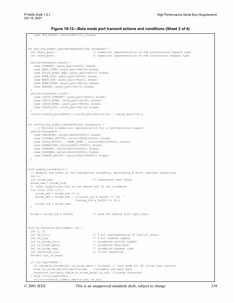
P1394b Draft 1.3.1 High Performance Serial Bus (Supplement)Oct 15, 2001
case BUS_RESET: return(0b1111); break;
int arb_req_symbol_map(BetaRequestCode txrequest) int async_part; // numerical representation of the asynchronous request type int isoch_part; // numerical representation of the isochronous request type switch(txrequest.async) case CURRENT: async_part=0b001; break; case NEXT_EVEN: async_part=0b010; break; case CYCLE_START_REQ: async_part=0b011; break; case NONE_ODD: async_part=0b100; break; case NEXT_ODD: async_part=0b101; break; case NONE_EVEN: async_part=0b110; break; case BORDER: async_part=0b111; break; switch(txrequest.isoch) case ISOCH_CURRENT: isoch_part=0b001; break; case ISOCH_EVEN: isoch_part=0b100; break; case ISOCH_NONE: isoch_part=0b010; break; case ISOCH_ODD: isoch_part=0b110; break; return((isoch_part&0b001)|((isoch_part&0b110)<<2) | (async_part<<5));
int config_req_symbol_map(ArbState txrequest) // Returns a numerical representation for a configuration request switch(txrequest) case TRAINING: return(0b00000000); break; case DISABLE_NOTIFY: return(0b00100000); break; case CHILD_NOTIFY | IDENT_DONE : return(0b01000000); break; case OPERATION: return(0b01100000); break; case STANDBY: return(0b10000000); break; case SUSPEND: return(0b10100000); break; case PARENT_NOTIFY: return(0b11000000); break;
void update_scrambler() // updates the state of the transmitter scrambler, performing 8 shift register operations int i; int scram_new; // represents next state scram_new = scram_old; // least significant bit is the newest bit in the scrambler for (i=0; i<8; i++) scram_new = scram_new << 1; scram_new = scram_new | (((scram_old & 0x400) >> 10) ^ ((scram_old & 0x100) >> 8)); scram_old = scram_new; scram = scram_old & 0x0FF; // used for XORing with input byte
void tx_character(portSymbol tx) int i, j; int tx_ctrl; // 4 bit representation of control state int tx_req; // 8 bit request symbol int tx_scram_ctrl; // scrambled control symbol int tx_scram_data; // scrambled data byte int tx_scram_req; // scrambled request type int character_out; // 10 bit character dataBit bit_to_send; if (tx.tag==DATA) if (disable_scrambler) tx_scram_data = tx.data; // test mode for TX jitter test pattern else tx_scram_data=tx.data^scram; //scramble the data byte character_out=data_table[tx_scram_data][tx_rd]; //lookup character else if(tx.tag==CTRL) tx_ctrl=control_symbol_map(tx.arb, tx_rd);
Figure 16-12Beta mode port transmit actions and conditions (Sheet 2 of 4)
© 2001 IEEE This is an unapproved standards draft, subject to change 339
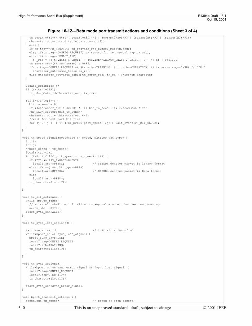
High Performance Serial Bus (Supplement) P1394b Draft 1.3.1Oct 15, 2001
tx_scram_ctrl=tx_ctrl^((scram&0x80)>>4 | (scram&0x20)>>3 | (scram&0x8)>>2 | (scram&0x2)>>1); character_out=control_table[tx_scram_ctrl]; else if(tx.tag==ARB_REQUEST) tx_req=arb_req_symbol_map(tx.req); else if(tx.tag==CONFIG_REQUEST) tx_req=config_req_symbol_map(tx.arb); else if(tx.tag==LEGACY_ARB) tx_req = (((tx.data & 0b011) | (tx.arb==LEGACY_PHASE ? 0b100 : 0)) << 5) | 0b01001; tx_scram_req=(tx_req^scram) & 0xF9; if(tx.tag==CONFIG_REQUEST && (tx.arb==TRAINING || tx.arb==OPERATION) && tx_scram_req==0x38) // D28.0 character_out=comma_table[tx_rd]; else character_out=data_table[tx_scram_req][tx_rd]; //lookup character update_scrambler(); if (tx.tag!=CTRL) tx_rd=update_rd(character_out, tx_rd); for(i=0;i<10;i++) bit_to_send = 0; if ((character_out & 0x200) != 0) bit_to_send = 1; //send msb first PMD_DATA_request(bit_to_send); character_out = character_out <<1; //wait for next port bit time for (j=0; j < (1 << (PHY_SPEED-port_speed));j++) wait_event(PH_BIT_CLOCK);
void tx_speed_signal(speedCode tx_speed, pktType pkt_type) int i; int j; j=port_speed - tx_speed; localT.tag=CTRL; for(i=0; i < 1<<(port_speed - tx_speed); i++) if(i==j && pkt_type==LEGACY) localT.arb=SPEEDa; // SPEEDa denotes packet is legacy format else if(i==j && pkt_type==BETA) localT.arb=SPEEDb; // SPEEDb denotes packet is Beta format else localT.arb=SPEEDc; tx_character(localT);
void tx_off_actions() while (power_reset) // scram_old shall be initialized to any value other than zero on power up scram_old = 0x7FF; bport_sync_ok=FALSE;
void tx_sync_lost_actions()
tx_rd=negative_rd; // initialization of rd while(bport_on && sync_lost_signal) bport_sync_ok=FALSE; localT.tag=CONFIG_REQUEST; localT.arb=TRAINING; tx_character(localT);
void tx_sync_actions() while(bport_on && sync_error_signal && !sync_lost_signal) localT.tag=CONFIG_REQUEST; localT.arb=OPERATION; tx_character(localT); bport_sync_ok=!sync_error_signal;
void bport_transmit_actions() speedCode tx_speed; // speed of each packet.
Figure 16-12Beta mode port transmit actions and conditions (Sheet 3 of 4)
340 This is an unapproved standards draft, subject to change © 2001 IEEE
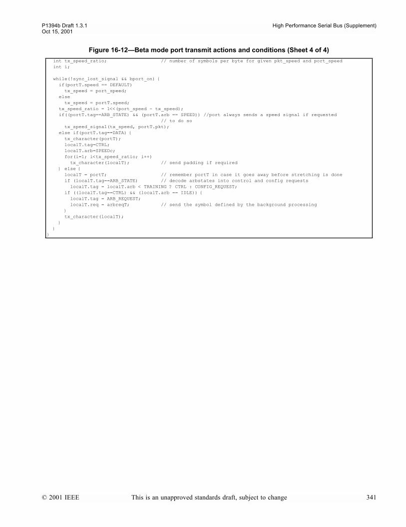
P1394b Draft 1.3.1 High Performance Serial Bus (Supplement)Oct 15, 2001
int tx_speed_ratio; // number of symbols per byte for given pkt_speed and port_speed int i; while(!sync_lost_signal && bport_on) if(portT.speed == DEFAULT) tx_speed = port_speed; else tx_speed = portT.speed; tx_speed_ratio = 1<<(port_speed - tx_speed); if((portT.tag==ARB_STATE) && (portT.arb == SPEED)) //port always sends a speed signal if requested // to do so tx_speed_signal(tx_speed, portT.pkt); else if(portT.tag==DATA) tx_character(portT); localT.tag=CTRL; localT.arb=SPEEDc; for(i=1; i<tx_speed_ratio; i++) tx_character(localT); // send padding if required else localT = portT; // remember portT in case it goes away before stretching is done if (localT.tag==ARB_STATE) // decode arbstates into control and config requests localT.tag = localT.arb < TRAINING ? CTRL : CONFIG_REQUEST; if ((localT.tag==CTRL) && (localT.arb == IDLE)) localT.tag = ARB_REQUEST; localT.req = arbreqT; // send the symbol defined by the background processing tx_character(localT);
Figure 16-12Beta mode port transmit actions and conditions (Sheet 4 of 4)
© 2001 IEEE This is an unapproved standards draft, subject to change 341
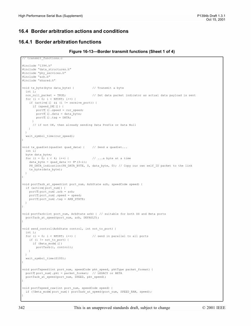
High Performance Serial Bus (Supplement) P1394b Draft 1.3.1Oct 15, 2001
16.4 Border arbitration actions and conditions
16.4.1 Border arbitration functions
Figure 16-13Border transmit functions (Sheet 1 of 4)
// transmit_functions.c
#include 1394.h#include data_structures.h#include phy_services.h#include arb.h#include shared.h
void tx_byte(byte data_byte) // Transmit a byte int i; non_null_packet = TRUE; // Set data packet indicator as actual data payload is sent for (i = 0; i < NPORT; i++) if (active[i] && (i != receive_port)) if (speed_OK[i]) portT[i].speed = cur_speed; portT[i].data = data_byte; portT[i].tag = DATA; // if not OK, then already sending Data Prefix or Data Null wait_symbol_time(cur_speed);
void tx_quadlet(quadlet quad_data) // Send a quadlet... int i; byte data_byte; for (i = 0; i < 4; i++) // ...a byte at a time data_byte = quad_data >> 8*(3-i); PH_DATA_indication(PH_DATA_BYTE, 0, data_byte, 0); // Copy our own self_ID packet to the link tx_byte(data_byte);
void portTarb_at_speed(int port_num, ArbState arb, speedCode speed) if (active[port_num]) portT[port_num].arb = arb; portT[port_num].speed = speed; portT[port_num].tag = ARB_STATE;
void portTarb(int port_num, ArbState arb) // suitable for both DS and Beta ports portTarb_at_speed(port_num, arb, DEFAULT);
void send_control(ArbState control, int not_to_port) int i; for (i = 0; i < NPORT; i++) // send in parallel to all ports if (i != not_to_port) if (Beta_mode[i]) portTarb(i, control); wait_symbol_time(S100);
void portTspeed(int port_num, speedCode pkt_speed, pktType packet_format) portT[port_num].pkt = packet_format; // LEGACY or BETA portTarb_at_speed(port_num, SPEED, pkt_speed);
void portTspeed_raw(int port_num, speedCode speed) if (!Beta_mode[port_num]) portTarb_at_speed(port_num, SPEED_RAW, speed);
342 This is an unapproved standards draft, subject to change © 2001 IEEE

P1394b Draft 1.3.1 High Performance Serial Bus (Supplement)Oct 15, 2001
// Send data prefix and do speed signalingvoid start_tx_packet(speedCode pkt_speed, pktType pkt, boolean send_cycle_start) int signal_port = NPORT, i; int deletable_symbol_time; // time for two symbols
if (!DS_stuck) max_beta_timer = 0; // timer only needs to be implemented in border capable nodes DS_stuck = TRUE; // and note that this will have to be released by sending // a Legacy format packet cur_speed = pkt_speed; // Remember speed and format of packet to transmit cur_format = pkt; legacy_phase_expected = FALSE; // set for check in stop_tx_packet non_null_packet = FALSE; // Reset data payload indicator at beginning of each new packet
// if granting a cycle start request, first send the appropriate cycle start token if (send_cycle_start) if (link == B_Link) // Alert link PH_DATA_indication(odd_isoch_phase ? PH_ISOCH_ODD: PH_ISOCH_EVEN, 0, 0, 0); for (i = 0; i < NPORT; i++) // Cycle start tokens are not sent on DS ports, if (!Beta_mode[i]) portTarb(i, DATA_PREFIX); // send DATA_PREFIX instead to prevent idle gap send_control(odd_isoch_phase ? CYCLE_START_ODD: CYCLE_START_EVEN, NPORT); iso_cycle = TRUE;
for (i = 0; i < NPORT; i++) if (active[i]) if (disable_request[i] && !phy_response) portTarb(signal_port = i, DISABLE_NOTIFY); else if (suspend_request[i] && !phy_response) portTarb(signal_port = i, SUSPEND); else if (do_standby[i] && !phy_response) portTarb(signal_port = i, STANDBY); if ((signal_port != NPORT) && (cur_speed > min_operating_speed)) cur_speed = min_operating_speed; // slow down to ensure four symbols on // any signaling port for (i = 0; i < NPORT; i++) if (!active[i]) // deal with inactive ports speed_OK[i] = FALSE; else if (!(disable_request[i] || suspend_request[i] || do_standby[i]) || phy_response) // normal packet speed_OK[i] = (cur_speed <= port_speed[i]) && (Beta_mode[i] || pkt == LEGACY); if ((pkt == LEGACY) && (link == Legacy_Link) && (cur_speed == S100)) portTarb(i, DATA_PREFIX); // suppress speedcode, send data prefix else if (speed_OK[i]) // send speed code portTspeed(i, cur_speed, pkt); else portTarb(i, pkt == LEGACY ? DATA_PREFIX : DATA_NULL); wait_symbol_time(cur_speed); // Wait till speed-sig symbol completed.
for (i = 0; i < NPORT; i++) if (!(disable_request[i] || suspend_request[i] || do_standby[i]) || phy_response) // Now send the next symbol on the Beta mode ports. if (Beta_mode[i]) portTarb(i, speed_OK[i] || pkt == LEGACY ? DATA_PREFIX : DATA_NULL);
// ensure timing for starting packet format, plus timing for deletable symbols
// The requirement is that the originating node shall insert two symbols // (one can delete and one must delete, and shall insert more symbols if // necessary to ensure that there is (approx) 40ns of deletable symbol time.
deletable_symbol_time = MIN_DELETABLE_SYMBOL_TIME; if ((cur_speed < S800) && (Legacy_symbol_count(cur_speed) * 2 > MIN_DELETABLE_SYMBOL_TIME)) deletable_symbol_time = Legacy_symbol_count(cur_speed) * 2; // or two symbol times
if (pkt == LEGACY) // therefore cur_speed < S800 // Leave the speed signal for longer, send the next symbol on the DS ports.
Figure 16-13Border transmit functions (Sheet 2 of 4)
© 2001 IEEE This is an unapproved standards draft, subject to change 343

High Performance Serial Bus (Supplement) P1394b Draft 1.3.1Oct 15, 2001
// waited 1, 2 or 4 Legacy_time units wait_Legacy_time(SPEED_SIGNAL_LENGTH - Legacy_symbol_count(cur_speed)); for (i = 0; i < NPORT; i++) if (!(disable_request[i] || suspend_request[i] || do_standby[i]) || phy_response) // Harmless writing this to the beta mode ports as well! portTarb(i, speed_OK[i] || pkt == LEGACY ? DATA_PREFIX : DATA_NULL); wait_Legacy_time(DATA_PREFIX_HOLD); // finish Data_Prefix // for S100 packets, must round up to two S100 symbol times // not used if a longer value of DATA_PREFIX_HOLD is used for Legacy interoperability // (see text) i.e. if the time to wait is <= 0 if (cur_speed == S100) wait_Legacy_time (2*Legacy_symbol_count(S100) - (SPEED_SIGNAL_LENGTH+DATA_PREFIX_HOLD)); else wait_symbol_time(cur_speed); wait_Legacy_time (deletable_symbol_time); if (signal_port != NPORT) // now waited a total of at least four symbol times when sending SUSPEND etc for (i = 0; i < NPORT; i++) // turn off signaled port(s) if ((disable_request[i] || suspend_request[i] || do_standby[i]) && !phy_response) portTarb(i, IDLE); signaled = (signal_port != NPORT);
void stop_tx_packet(ArbState ending_status, int port_to_grant) int i, hold_time; ArbState tx_arb; switch (ending_status) case DATA_PREFIX: // current talker is holding onto case DATA_NULL: // the bus to form a concatenation hold_time = CONCATENATION_PREFIX_TIME; tx_arb = ending_status; break; case GRANT: case GRANT_ISOCH: if (port_to_grant == senior_port) // grant to senior releases bus hold_time = DATA_END_TIME; tx_arb = DATA_END; DS_stuck = (cur_format != LEGACY); else if ((receive_port == NPORT) && (port_to_grant == NPORT)) // grant to link for concatenation without fear of overwriting IDLE on receive port hold_time = CONCATENATION_PREFIX_TIME; tx_arb = DATA_NULL; else // grant to junior/link taking care not to overwrite IDLE on receive port hold_time = DATA_END_TIME; tx_arb = DATA_NULL; break; case DATA_END: hold_time = DATA_END_TIME; tx_arb = DATA_END; DS_stuck = (cur_format != LEGACY); break; case IDLE: case ARB_CONTEXT: tx_arb = ending_status; DS_stuck = (cur_format != LEGACY); break; case BUS_RESET: tx_arb = BUS_RESET; DS_stuck = FALSE; break; default: break;
if ((tx_arb == BUS_RESET) || (tx_arb == IDLE)) return; // Immediate exit to R0 or A0
for (i = 0; i < NPORT; i++) if (!(Beta_mode[i] && port_to_grant == i) && (i != receive_port))
Figure 16-13Border transmit functions (Sheet 3 of 4)
344 This is an unapproved standards draft, subject to change © 2001 IEEE
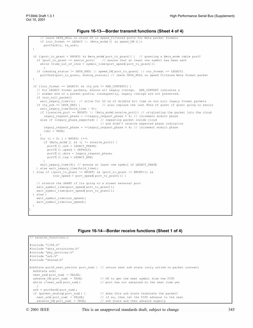
P1394b Draft 1.3.1 High Performance Serial Bus (Supplement)Oct 15, 2001
// leave DATA_NULL on stuck DS or speed_filtered ports for Beta packet formats if (cur_format == LEGACY || (Beta_mode[i] && speed_OK[i])) portTarb(i, tx_arb);
if ((port_to_grant < NPORT) && Beta_mode[port_to_grant]) // granting a Beta_mode cable port? if (port_to_grant == senior_port) // ensure that at least one symbol has been sent while (time_out_of_idle < symbol_time(port_speed[port_to_grant])) ; if ((ending_status != DATA_END) || speed_OK[port_to_grant] || cur_format == LEGACY) portTarb(port_to_grant, ending_status); // leave DATA_NULL on speed filtered Beta format packet
if ((cur_format == LEGACY) && (tx_arb != ARB_CONTEXT)) // For LEGACY format packets, ensure all Legacy timings. ARB_CONTEXT indicates a // sudden end of a packet prefix; consequently, Legacy timings are not preserved. if (non_null_packet) wait_Legacy_time(1); // allow for 20 ns of dribble bit time on non null legacy format packets if (tx_arb == DATA_END) // also replace the last 80ns of grant if grant going to senior wait_Legacy_time(hold_time - 4); if ((receive_port == NPORT) || !Beta_mode[receive_port]) // originating the packet into the cloud legacy_request_phase = ++legacy_request_phase % 4; // increment modulo phase else if (legacy_phase_expected) // repeating packet inside cloud // and didnt receive expected phase indication legacy_request_phase = ++legacy_request_phase % 4; // increment modulo phase isbr = TRUE; for (i = 0; i < NPORT; i++) if (Beta_mode[i] && (i != receive_port)) portT[i].arb = LEGACY_PHASE; portT[i].speed = DEFAULT; portT[i].data = legacy_request_phase; portT[i].tag = LEGACY_ARB; wait_Legacy_time(4); // ensure at least one symbol of LEGACY_PHASE else wait_Legacy_time(hold_time); else if ((port_to_grant != NPORT) && (port_to_grant != NPORT+1) && (cur_speed > port_speed[port_to_grant])) // stretch the GRANT if its going to a slower external port wait_symbol_time(port_speed[port_to_grant]); wait_symbol_time(port_speed[port_to_grant]); else wait_symbol_time(cur_speed); wait_symbol_time(cur_speed);
Figure 16-14Border receive functions (Sheet 1 of 4)
// receive_functions.c
#include 1394.h#include data_structures.h#include phy_services.h#include arb.h#include shared.h
ArbState portR_next_arb(int port_num) // return next arb state (only called in packet context) ArbState arb; next_arb[port_num] = FALSE; advance_OK[port_num] = TRUE; // OK to get the next symbol from the FIFO while (!next_arb[port_num]) // port has not advanced to the next item yet ; arb = portRarb[port_num]; if (packet_ending[port_num]) // does this arb state terminate the packet? next_arb[port_num] = FALSE; // if so, then let the FIFO advance to the next advance_OK[port_num] = TRUE; // arb state and then advance eagerly
Figure 16-13Border transmit functions (Sheet 4 of 4)
© 2001 IEEE This is an unapproved standards draft, subject to change 345
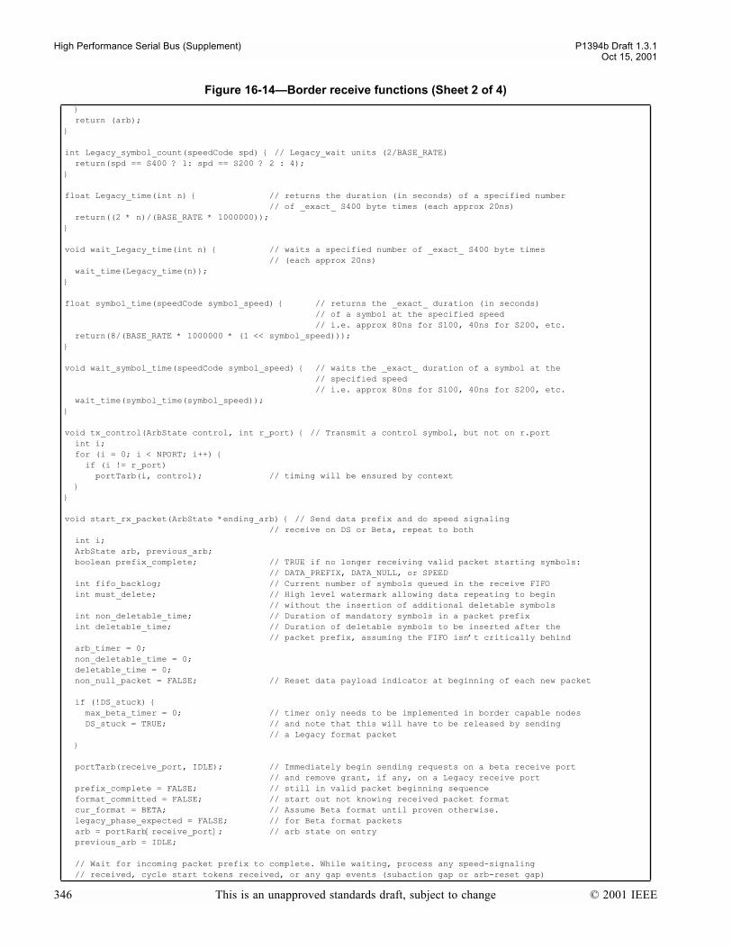
High Performance Serial Bus (Supplement) P1394b Draft 1.3.1Oct 15, 2001
return (arb);
int Legacy_symbol_count(speedCode spd) // Legacy_wait units (2/BASE_RATE) return(spd == S400 ? 1: spd == S200 ? 2 : 4);
float Legacy_time(int n) // returns the duration (in seconds) of a specified number // of _exact_ S400 byte times (each approx 20ns) return((2 * n)/(BASE_RATE * 1000000));
void wait_Legacy_time(int n) // waits a specified number of _exact_ S400 byte times // (each approx 20ns) wait_time(Legacy_time(n));
float symbol_time(speedCode symbol_speed) // returns the _exact_ duration (in seconds) // of a symbol at the specified speed // i.e. approx 80ns for S100, 40ns for S200, etc. return(8/(BASE_RATE * 1000000 * (1 << symbol_speed)));
void wait_symbol_time(speedCode symbol_speed) // waits the _exact_ duration of a symbol at the // specified speed // i.e. approx 80ns for S100, 40ns for S200, etc. wait_time(symbol_time(symbol_speed));
void tx_control(ArbState control, int r_port) // Transmit a control symbol, but not on r.port int i; for (i = 0; i < NPORT; i++) if (i != r_port) portTarb(i, control); // timing will be ensured by context
void start_rx_packet(ArbState *ending_arb) // Send data prefix and do speed signaling // receive on DS or Beta, repeat to both int i; ArbState arb, previous_arb; boolean prefix_complete; // TRUE if no longer receiving valid packet starting symbols: // DATA_PREFIX, DATA_NULL, or SPEED int fifo_backlog; // Current number of symbols queued in the receive FIFO int must_delete; // High level watermark allowing data repeating to begin // without the insertion of additional deletable symbols int non_deletable_time; // Duration of mandatory symbols in a packet prefix int deletable_time; // Duration of deletable symbols to be inserted after the // packet prefix, assuming the FIFO isnt critically behind arb_timer = 0; non_deletable_time = 0; deletable_time = 0; non_null_packet = FALSE; // Reset data payload indicator at beginning of each new packet
if (!DS_stuck) max_beta_timer = 0; // timer only needs to be implemented in border capable nodes DS_stuck = TRUE; // and note that this will have to be released by sending // a Legacy format packet
portTarb(receive_port, IDLE); // Immediately begin sending requests on a beta receive port // and remove grant, if any, on a Legacy receive port prefix_complete = FALSE; // still in valid packet beginning sequence format_committed = FALSE; // start out not knowing received packet format cur_format = BETA; // Assume Beta format until proven otherwise. legacy_phase_expected = FALSE; // for Beta format packets arb = portRarb[receive_port]; // arb state on entry previous_arb = IDLE;
// Wait for incoming packet prefix to complete. While waiting, process any speed-signaling // received, cycle start tokens received, or any gap events (subaction gap or arb-reset gap)
Figure 16-14Border receive functions (Sheet 2 of 4)
346 This is an unapproved standards draft, subject to change © 2001 IEEE
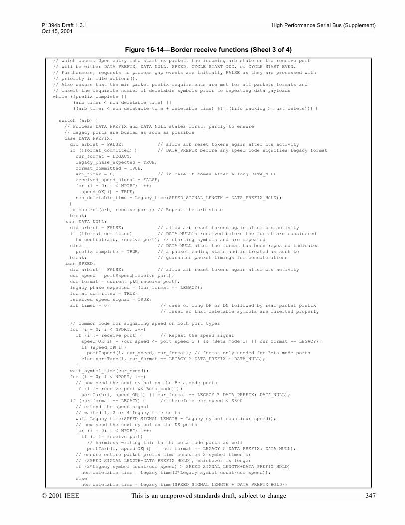
P1394b Draft 1.3.1 High Performance Serial Bus (Supplement)Oct 15, 2001
// which occur. Upon entry into start_rx_packet, the incoming arb state on the receive_port // will be either DATA_PREFIX, DATA_NULL, SPEED, CYCLE_START_ODD, or CYCLE_START_EVEN. // Furthermore, requests to process gap events are initially FALSE as they are processed with // priority in idle_actions(). // Also ensure that the min packet prefix requirements are met for all packets formats and // insert the requisite number of deletable symbols prior to repeating data payloads while (!prefix_complete || (arb_timer < non_deletable_time) || ((arb_timer < non_deletable_time + deletable_time) && !(fifo_backlog > must_delete)))
switch (arb) // Process DATA_PREFIX and DATA_NULL states first, partly to ensure // Legacy ports are busied as soon as possible case DATA_PREFIX: did_arbrst = FALSE; // allow arb reset tokens again after bus activity if (!format_committed) // DATA_PREFIX before any speed code signifies Legacy format cur_format = LEGACY; legacy_phase_expected = TRUE; format_committed = TRUE; arb_timer = 0; // in case it comes after a long DATA_NULL received_speed_signal = FALSE; for (i = 0; i < NPORT; i++) speed_OK[i] = TRUE; non_deletable_time = Legacy_time(SPEED_SIGNAL_LENGTH + DATA_PREFIX_HOLD); tx_control(arb, receive_port); // Repeat the arb state break; case DATA_NULL: did_arbrst = FALSE; // allow arb reset tokens again after bus activity if (!format_committed) // DATA_NULLs received before the format are considered tx_control(arb, receive_port); // starting symbols and are repeated else // DATA_NULL after the format has been repeated indicates prefix_complete = TRUE; // a packet ending state and is treated as such to break; // guarantee packet timings for concatenations case SPEED: did_arbrst = FALSE; // allow arb reset tokens again after bus activity cur_speed = portRspeed[receive_port]; cur_format = current_pkt[receive_port]; legacy_phase_expected = (cur_format == LEGACY); format_committed = TRUE; received_speed_signal = TRUE; arb_timer = 0; // case of long DP or DN followed by real packet prefix // reset so that deletable symbols are inserted properly
// common code for signaling speed on both port types for (i = 0; i < NPORT; i++) if (i != receive_port) // Repeat the speed signal speed_OK[i] = (cur_speed <= port_speed[i]) && (Beta_mode[i] || cur_format == LEGACY); if (speed_OK[i]) portTspeed(i, cur_speed, cur_format); // format only needed for Beta mode ports else portTarb(i, cur_format == LEGACY ? DATA_PREFIX : DATA_NULL); wait_symbol_time(cur_speed); for (i = 0; i < NPORT; i++) // now send the next symbol on the Beta mode ports if (i != receive_port && Beta_mode[i]) portTarb(i, speed_OK[i] || cur_format == LEGACY ? DATA_PREFIX: DATA_NULL); if (cur_format == LEGACY) // therefore cur_speed < S800 // extend the speed signal // waited 1, 2 or 4 Legacy_time units wait_Legacy_time(SPEED_SIGNAL_LENGTH - Legacy_symbol_count(cur_speed)); // now send the next symbol on the DS ports for (i = 0; i < NPORT; i++) if (i != receive_port) // harmless writing this to the beta mode ports as well portTarb(i, speed_OK[i] || cur_format == LEGACY ? DATA_PREFIX: DATA_NULL); // ensure entire packet prefix time consumes 2 symbol times or // (SPEED_SIGNAL_LENGTH+DATA_PREFIX_HOLD), whichever is longer if (2*Legacy_symbol_count(cur_speed) > SPEED_SIGNAL_LENGTH+DATA_PREFIX_HOLD) non_deletable_time = Legacy_time(2*Legacy_symbol_count(cur_speed)); else non_deletable_time = Legacy_time(SPEED_SIGNAL_LENGTH + DATA_PREFIX_HOLD);
Figure 16-14Border receive functions (Sheet 3 of 4)
© 2001 IEEE This is an unapproved standards draft, subject to change 347

High Performance Serial Bus (Supplement) P1394b Draft 1.3.1Oct 15, 2001
else // not Legacy format non_deletable_time = 2*symbol_time(cur_speed); break; case CYCLE_START_ODD: case CYCLE_START_EVEN: did_arbrst = FALSE; // allow arb reset tokens again after bus activity if (!format_committed) // always expect cycle start token before format indication odd_isoch_phase = (arb == CYCLE_START_ODD); if (link == B_Link) // Alert link PH_DATA_indication(odd_isoch_phase ? PH_ISOCH_ODD: PH_ISOCH_EVEN, 0, 0, 0); for (i = 0; i < NPORT; i++) // Cycle start tokens are not sent on DS ports, if (!Beta_mode[i]) portTarb(i, DATA_PREFIX); // send DATA_PREFIX instead to prevent idle gap send_control(odd_isoch_phase ? CYCLE_START_ODD: CYCLE_START_EVEN, receive_port); iso_cycle = TRUE; // After repeating cycle start token, treat as if a DATA_NULL had been received tx_control(DATA_NULL, receive_port); arb_timer = 0; // so that CST symbols are not treated as packet prefix symbols else // error case, token received after packet formatting prefix_complete = TRUE; // treat as ending symbol of mal-formed packet break; case DATA_BYTE: did_arbrst = FALSE; // allow arb reset tokens again after bus activity prefix_complete = TRUE; // When sending data, requirement is to send deletable symbols for at least one packet symbol // or 20 ns, whichever is greater (provided the FIFO isnt in a critical state). Since, the // underflow prevention logic used to center the FIFO unconditionally inserts 20ns of time, // additional time is only provided within this loop for packet symbol times which are larger // than 20 ns: namely, S100 and S200 speeds. if ((cur_speed == S100) || (cur_speed == S200)) deletable_time = Legacy_time(Legacy_symbol_count(cur_speed) - Legacy_symbol_count(S400)); must_delete = cur_speed == S3200 ? 16 : cur_speed == S1600 ? 8 : cur_speed == S800 ? 4 : 2; // nominal 40 ns, or two symbol for S200 and S100 break;
case ASYNC_EVEN: case ASYNC_ODD: // Process each distinct gap token received within a packet prefix by ensuring that filters // applied in gap_token() are disabled filter_async_even = FALSE; filter_async_odd = FALSE; if (gap_token(receive_port)) // always returns true since filters have been cleared gap_repeat_actions(receive_port); portTarb(receive_port, IDLE); // restore the ports to previous state arb = previous_arb; // and prevent the code below picking up the token tx_control(arb, receive_port); break; default: // any other arb signal indicates packet prefix has concluded, prefix_complete = TRUE; // exit loop after prefix timings have been met break;
// if still in the packet prefix, advance the FIFO to the next arbitration indication if (!prefix_complete) previous_arb = arb; // arb has been backed off if a token arb = portR_next_arb(receive_port); fifo_backlog = (FIFO_DEPTH + fifo_wr_ptr[receive_port] - fifo_rd_ptr[receive_port]) % FIFO_DEPTH;
if (arb == DATA_BYTE || arb == DATA_END) // Actually receiving a packet or at packet end? // wait on DE in order not to miss a possible LEGACY_PHASE arb_timer = 0; while (!(fifo_backlog > must_delete) && (arb_timer < Legacy_time(Legacy_symbol_count(S400)))) // Allow time for the FIFO to load, but start repeat immediately if critical fifo_backlog = (FIFO_DEPTH + fifo_wr_ptr[receive_port] - fifo_rd_ptr[receive_port]) % FIFO_DEPTH; *ending_arb = arb; // final arb which was read
Figure 16-14Border receive functions (Sheet 4 of 4)
348 This is an unapproved standards draft, subject to change © 2001 IEEE
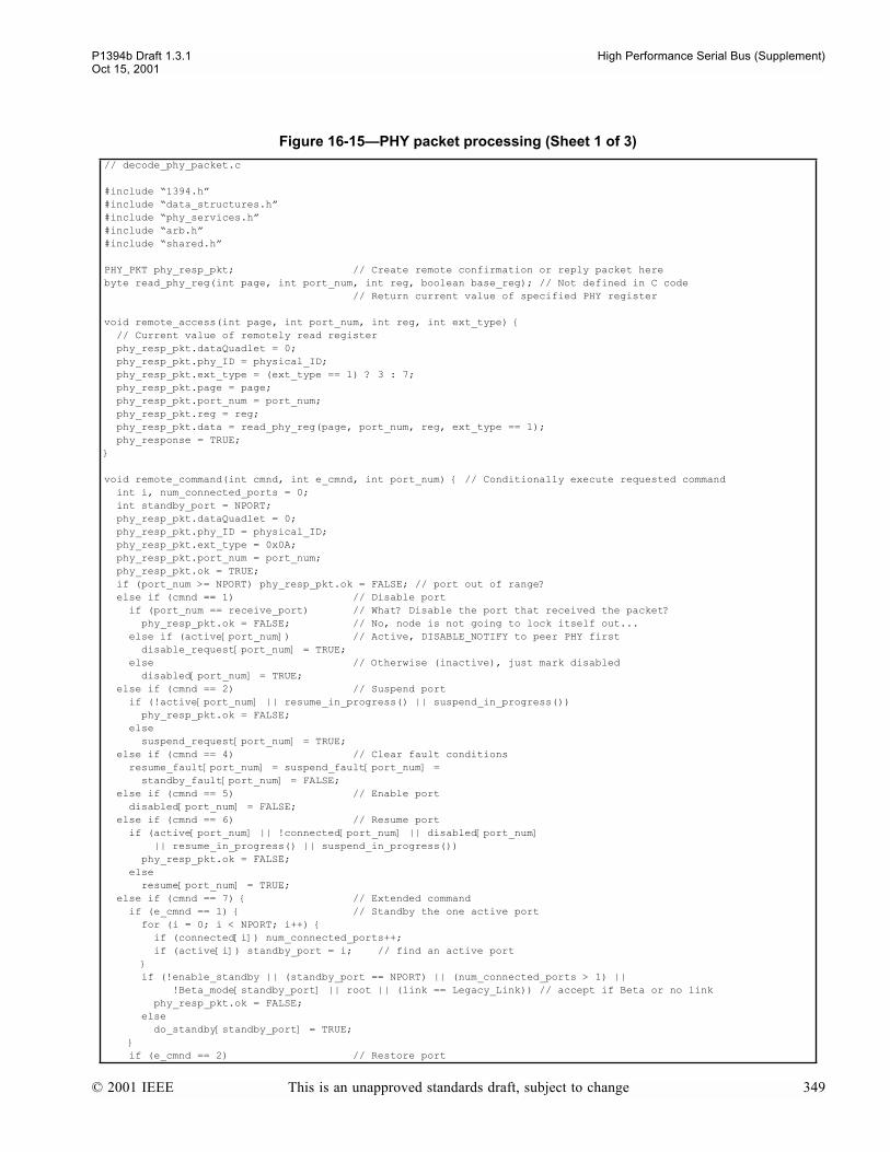
P1394b Draft 1.3.1 High Performance Serial Bus (Supplement)Oct 15, 2001
Figure 16-15PHY packet processing (Sheet 1 of 3)
// decode_phy_packet.c
#include 1394.h#include data_structures.h#include phy_services.h#include arb.h#include shared.h
PHY_PKT phy_resp_pkt; // Create remote confirmation or reply packet herebyte read_phy_reg(int page, int port_num, int reg, boolean base_reg); // Not defined in C code // Return current value of specified PHY register
void remote_access(int page, int port_num, int reg, int ext_type) // Current value of remotely read register phy_resp_pkt.dataQuadlet = 0; phy_resp_pkt.phy_ID = physical_ID; phy_resp_pkt.ext_type = (ext_type == 1) ? 3 : 7; phy_resp_pkt.page = page; phy_resp_pkt.port_num = port_num; phy_resp_pkt.reg = reg; phy_resp_pkt.data = read_phy_reg(page, port_num, reg, ext_type == 1); phy_response = TRUE;
void remote_command(int cmnd, int e_cmnd, int port_num) // Conditionally execute requested command int i, num_connected_ports = 0; int standby_port = NPORT; phy_resp_pkt.dataQuadlet = 0; phy_resp_pkt.phy_ID = physical_ID; phy_resp_pkt.ext_type = 0x0A; phy_resp_pkt.port_num = port_num; phy_resp_pkt.ok = TRUE; if (port_num >= NPORT) phy_resp_pkt.ok = FALSE; // port out of range? else if (cmnd == 1) // Disable port if (port_num == receive_port) // What? Disable the port that received the packet? phy_resp_pkt.ok = FALSE; // No, node is not going to lock itself out... else if (active[port_num]) // Active, DISABLE_NOTIFY to peer PHY first disable_request[port_num] = TRUE; else // Otherwise (inactive), just mark disabled disabled[port_num] = TRUE; else if (cmnd == 2) // Suspend port if (!active[port_num] || resume_in_progress() || suspend_in_progress()) phy_resp_pkt.ok = FALSE; else suspend_request[port_num] = TRUE; else if (cmnd == 4) // Clear fault conditions resume_fault[port_num] = suspend_fault[port_num] = standby_fault[port_num] = FALSE; else if (cmnd == 5) // Enable port disabled[port_num] = FALSE; else if (cmnd == 6) // Resume port if (active[port_num] || !connected[port_num] || disabled[port_num] || resume_in_progress() || suspend_in_progress()) phy_resp_pkt.ok = FALSE; else resume[port_num] = TRUE; else if (cmnd == 7) // Extended command if (e_cmnd == 1) // Standby the one active port for (i = 0; i < NPORT; i++) if (connected[i]) num_connected_ports++; if (active[i]) standby_port = i; // find an active port if (!enable_standby || (standby_port == NPORT) || (num_connected_ports > 1) || !Beta_mode[standby_port] || root || (link == Legacy_Link)) // accept if Beta or no link phy_resp_pkt.ok = FALSE; else do_standby[standby_port] = TRUE; if (e_cmnd == 2) // Restore port
© 2001 IEEE This is an unapproved standards draft, subject to change 349

High Performance Serial Bus (Supplement) P1394b Draft 1.3.1Oct 15, 2001
if (active[port_num] || !connected[port_num] || disabled[port_num]) phy_resp_pkt.ok = FALSE; else restore[port_num] = TRUE; if (!((cmnd == 7) && (e_cmnd == 1))) // fields ignored on standby command phy_resp_pkt.standby_fault = standby_fault[port_num]; phy_resp_pkt.fault = fault[port_num]; phy_resp_pkt.connected = connected[port_num]; phy_resp_pkt.bias = receive_ok[port_num]; phy_resp_pkt.disabled = disabled[port_num]; phy_resp_pkt.cmnd = cmnd; phy_resp_pkt.e_cmnd = e_cmnd; phy_response = TRUE;
void decode_phy_packet(PHY_PKT phy_pkt) int i; boolean LTP_packet; LTP_packet = FALSE; if (phy_pkt.phy_pktType == 0b10) // self_ID packet? self_ID_pkt = phy_pkt; if (bus_initialize_active) // note, cant do this processing in self_ID receive_actions, // as self_IDs from the parental side are received in normal arbitration // look for PHY speed to set max_Legacy_path_speed B_node_root = received_speed_signal; // finally set by the last self_ID received if ((self_ID_pkt.ext == 0) && (!Beta_mode[receive_port] || !received_speed_signal)) // originated from node with Legacy link or DS node B_bus = FALSE; switch (self_ID_pkt.sp) case 0b00: break; case 0b01: max_Legacy_path_speed = (max_Legacy_path_speed == S100) ? S200: max_Legacy_path_speed; break; default: max_Legacy_path_speed = S400; break; // Always assume the latest advertised border is the proxy_root. proxy_root may be // set true later if this PHY still has to send its own self_ID proxy_root = FALSE; senior_port = receive_port; // remember the path to the latest candidate proxy_root // Always assume the latest advertised border within the local Beta cloud is the // senior border. senior_border may be set true later if this PHY still has to send // its own self_ID. if (Beta_mode[receive_port]) senior_border = FALSE; else if (phy_pkt.phy_pktType == 0b01) // Link-on packet? if (phy_pkt.phy_ID == physical_ID) PH_EVENT_indication(PH_LINK_ON, 0, 0); // LinkOn asserted only if either LPS or LCtrl FALSE else if (phy_pkt.R != 0 || phy_pkt.T != 0) // PHY configuration packet? if (phy_pkt.R == 1) // Set force_root if address matches force_root = (phy_pkt.root_ID == physical_ID); if (phy_pkt.T == 1) // Set gap_count regardless of physical ID gap_count = phy_pkt.gap_count; gap_count_reset_disable = TRUE; else if (phy_pkt.ext_type == 0) // Ping packet? ping_response = (phy_pkt.phy_ID == physical_ID); else if ((phy_pkt.ext_type == 1 || phy_pkt.ext_type == 5) && phy_pkt.phy_ID == physical_ID) remote_access(phy_pkt.page, phy_pkt.port_num, phy_pkt.reg, phy_pkt.ext_type); else if (phy_pkt.ext_type == 8 && phy_pkt.phy_ID == physical_ID) remote_command(phy_pkt.cmnd, phy_pkt.e_cmnd, phy_pkt.port_num); else if (phy_pkt.ext_type == 0xF) // Resume packet? for (i = 0; i < NPORT; i++) if (!active[i] && !disabled[i] && connected[i])
Figure 16-15PHY packet processing (Sheet 2 of 3)
350 This is an unapproved standards draft, subject to change © 2001 IEEE

P1394b Draft 1.3.1 High Performance Serial Bus (Supplement)Oct 15, 2001
resume[i] = TRUE; // Resume all suspended/suspending ports else if (phy_pkt.ext_type == 0xE) // LTP packet? HR_mode = phy_pkt.mode; HR_G = phy_pkt.G; HR_test_value = phy_pkt.test_value; need_new_LTP = FALSE; test_interval_timer = 0; LTP_packet = TRUE; if (!LTP_packet) HR_mode = LTP_TEST; // reset on all PHY packets except LTP packets
void phy_response_actions() receive_port = NPORT; // local node is transmitting (no port has this number) PH_ARB_confirmation(PH_LOST, 0, 0); // Inform link of upcoming cancellation period if ((breq == FAIR_REQ) || (breq == PRIORITY_REQ)) breq = NO_REQ; // Cancel any asynchronous request PH_DATA_indication(PH_DATA_PREFIX, 0, 0, 0); // Send notification of bus activity start_tx_packet(S100, LEGACY, FALSE); // send data prefix and 98.304 Mbit/sec speed code PH_DATA_indication(PH_DATA_START, S100, 0, LEGACY); // cc the link (always) tx_quadlet(phy_resp_pkt.dataQuadlet); tx_quadlet(~phy_resp_pkt.dataQuadlet); // not able to call boss_end_packet_actions here, as then the node would have to allow// for concatenating another packet, and theres complications with the possible// isbr below, also cannot mark a PHY response packet from a suspend or disable // as being the end of subaction, so give an implicit grant and return to Idle
PH_DATA_indication(PH_DATA_END, 0, 0, 0); stop_tx_packet(DATA_END, NPORT); if ((phy_resp_pkt.ext_type == 0x0A) && (phy_resp_pkt.ok == 1)) if (disable_request[phy_resp_pkt.port_num] || phy_resp_pkt.cmnd == 2) isbr = isbr_OK = TRUE; // Bus reset active ports if disable or suspend immediate_phy_request = TRUE; // To keep control to send the SUSPEND or DISABLE if ((phy_resp_pkt.cmnd == 7) && (phy_resp_pkt.e_cmnd == 1)) immediate_phy_request = TRUE; // To keep control to send the STANDBY phy_response = FALSE;
Figure 16-16Legacy arbitration functions (Sheet 1 of 3)
// ds_arb_functions.c
#include 1394.h#include data_structures.h#include phy_services.h#include arb.h#include shared.h
boolean fly_by_permitted() // TRUE if fly-by acceleration OK if (!(link_CS_indications || root)) // Legacy links at root dont provide indications return(FALSE); else if (receive_port == senior_port) return(FALSE); else if (req_speed == S100 && cur_speed != S100) return(FALSE); else if (breq == ISOCH_REQ) return(TRUE); else if (ack && (accelerating || root)) return(breq == PRIORITY_REQ || (breq == FAIR_REQ && arb_enable)); else return(FALSE);
boolean Legacy_junior_requesting() int i;
Figure 16-15PHY packet processing (Sheet 3 of 3)
© 2001 IEEE This is an unapproved standards draft, subject to change 351
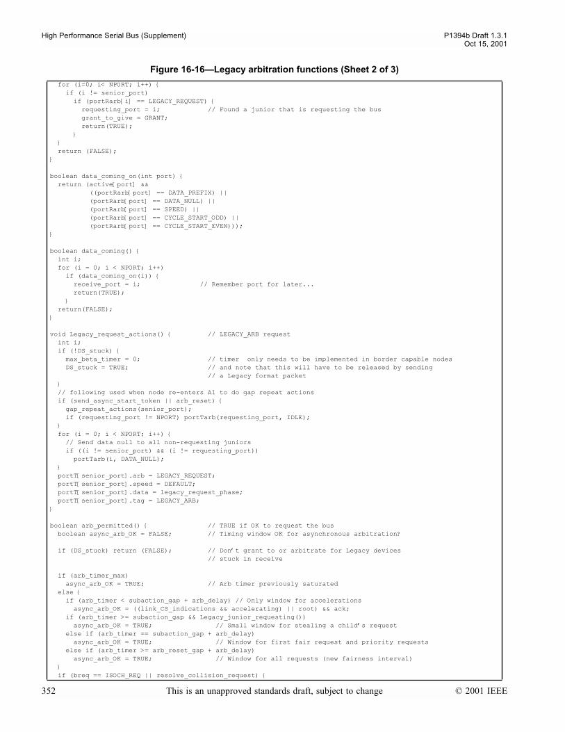
High Performance Serial Bus (Supplement) P1394b Draft 1.3.1Oct 15, 2001
for (i=0; i< NPORT; i++) if (i != senior_port) if (portRarb[i] == LEGACY_REQUEST) requesting_port = i; // Found a junior that is requesting the bus grant_to_give = GRANT; return(TRUE); return (FALSE);
boolean data_coming_on(int port) return (active[port] && ((portRarb[port] == DATA_PREFIX) || (portRarb[port] == DATA_NULL) || (portRarb[port] == SPEED) || (portRarb[port] == CYCLE_START_ODD) || (portRarb[port] == CYCLE_START_EVEN)));
boolean data_coming() int i; for (i = 0; i < NPORT; i++) if (data_coming_on(i)) receive_port = i; // Remember port for later... return(TRUE); return(FALSE);
void Legacy_request_actions() // LEGACY_ARB request int i; if (!DS_stuck) max_beta_timer = 0; // timer only needs to be implemented in border capable nodes DS_stuck = TRUE; // and note that this will have to be released by sending // a Legacy format packet // following used when node re-enters A1 to do gap repeat actions if (send_async_start_token || arb_reset) gap_repeat_actions(senior_port); if (requesting_port != NPORT) portTarb(requesting_port, IDLE); for (i = 0; i < NPORT; i++) // Send data null to all non-requesting juniors if ((i != senior_port) && (i != requesting_port)) portTarb(i, DATA_NULL); portT[senior_port].arb = LEGACY_REQUEST; portT[senior_port].speed = DEFAULT; portT[senior_port].data = legacy_request_phase; portT[senior_port].tag = LEGACY_ARB;
boolean arb_permitted() // TRUE if OK to request the bus boolean async_arb_OK = FALSE; // Timing window OK for asynchronous arbitration?
if (DS_stuck) return (FALSE); // Dont grant to or arbitrate for Legacy devices // stuck in receive
if (arb_timer_max) async_arb_OK = TRUE; // Arb timer previously saturated else if (arb_timer < subaction_gap + arb_delay) // Only window for accelerations async_arb_OK = ((link_CS_indications && accelerating) || root) && ack; if (arb_timer >= subaction_gap && Legacy_junior_requesting()) async_arb_OK = TRUE; // Small window for stealing a childs request else if (arb_timer == subaction_gap + arb_delay) async_arb_OK = TRUE; // Window for first fair request and priority requests else if (arb_timer >= arb_reset_gap + arb_delay) async_arb_OK = TRUE; // Window for all requests (new fairness interval) if (breq == ISOCH_REQ || resolve_collision_request)
Figure 16-16Legacy arbitration functions (Sheet 2 of 3)
352 This is an unapproved standards draft, subject to change © 2001 IEEE
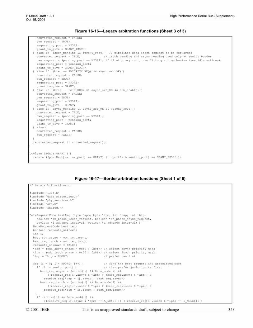
P1394b Draft 1.3.1 High Performance Serial Bus (Supplement)Oct 15, 2001
converted_request = FALSE; own_request = TRUE; requesting_port = NPORT; grant_to_give = GRANT_ISOCH; else if (isoch_pending && !proxy_root) // pipelined Beta isoch request to be forwarded converted_request = TRUE; // isoch_pending and async_pending used only at senior_border own_request = (pending_port == NPORT); // if at proxy_root, use OK_to_grant mechanism (see idle_actions). requesting_port = pending_port; grant_to_give = GRANT_ISOCH; else if ((breq == PRIORITY_REQ) && async_arb_OK) converted_request = FALSE; own_request = TRUE; requesting_port = NPORT; grant_to_give = GRANT; else if ((breq == FAIR_REQ) && async_arb_OK && arb_enable) converted_request = FALSE; own_request = TRUE; requesting_port = NPORT; grant_to_give = GRANT; else if (async_pending && async_arb_OK && !proxy_root) converted_request = TRUE; own_request = (pending_port == NPORT); requesting_port = pending_port; grant_to_give = GRANT; else converted_request = FALSE; own_request = FALSE; return(own_request || converted_request);
boolean LEGACY_GRANT() return ((portRarb[senior_port] == GRANT) || (portRarb[senior_port] == GRANT_ISOCH));
Figure 16-17Border arbitration functions (Sheet 1 of 6)
// beta_arb_functions.c
#include 1394.h#include data_structures.h#include phy_services.h#include arb.h#include shared.h
BetaRequestCode bestReq (byte *apm, byte *ipm, int *bap, int *bip, boolean *in_phase_isoch_request, boolean *in_phase_async_request, boolean *i_advance_interval, boolean *a_advance_interval) BetaRequestCode best_req; boolean requests_unknown; int i; best_req.async = own_req.async; best_req.isoch = own_req.isoch; requests_unknown = FALSE; *apm = (odd_async_phase ? 0xf0 : 0x0f); // select async priority mask *ipm = (odd_isoch_phase ? 0xf0 : 0x0f); // select isoch priority mask *bap = *bip = NPORT; // prefer own link
for (i = 0; i < NPORT; i++) // find the best request and associated port if (i != senior_port) // then prefer junior ports first best_req.async = (active[i] && Beta_mode[i] && ((receive_req[i].async & *apm) > (best_req.async & *apm)) ? receive_req[*bap = i].async : best_req.async); best_req.isoch = (active[i] && Beta_mode[i] && ((receive_req[i].isoch & *ipm) > (best_req.isoch & *ipm)) ? receive_req[*bip = i].isoch : best_req.isoch); if (active[i] && Beta_mode[i] && (((receive_req[i].async & *apm) == A_NONE) || ((receive_req[i].isoch & *ipm) == I_NONE)))
Figure 16-16Legacy arbitration functions (Sheet 3 of 3)
© 2001 IEEE This is an unapproved standards draft, subject to change 353
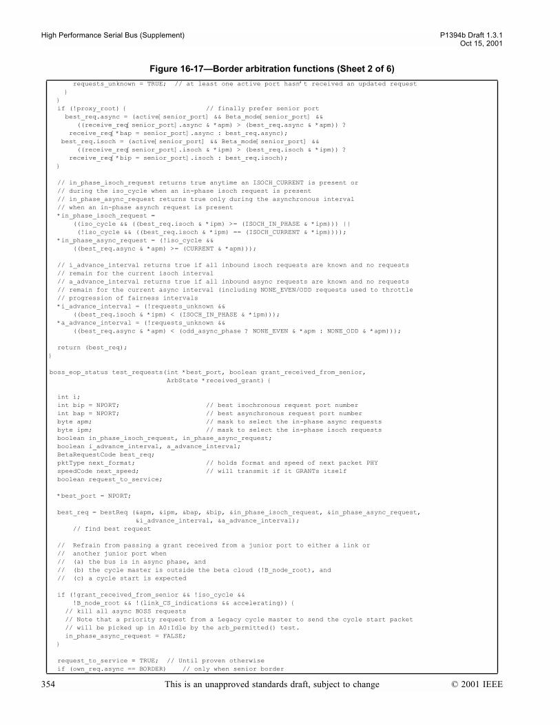
High Performance Serial Bus (Supplement) P1394b Draft 1.3.1Oct 15, 2001
requests_unknown = TRUE; // at least one active port hasnt received an updated request if (!proxy_root) // finally prefer senior port best_req.async = (active[senior_port] && Beta_mode[senior_port] && ((receive_req[senior_port].async & *apm) > (best_req.async & *apm)) ? receive_req[*bap = senior_port].async : best_req.async); best_req.isoch = (active[senior_port] && Beta_mode[senior_port] && ((receive_req[senior_port].isoch & *ipm) > (best_req.isoch & *ipm)) ? receive_req[*bip = senior_port].isoch : best_req.isoch); // in_phase_isoch_request returns true anytime an ISOCH_CURRENT is present or // during the iso_cycle when an in-phase isoch request is present // in_phase_async_request returns true only during the asynchronous interval // when an in-phase asynch request is present *in_phase_isoch_request = ((iso_cycle && ((best_req.isoch & *ipm) >= (ISOCH_IN_PHASE & *ipm))) || (!iso_cycle && ((best_req.isoch & *ipm) == (ISOCH_CURRENT & *ipm)))); *in_phase_async_request = (!iso_cycle && ((best_req.async & *apm) >= (CURRENT & *apm)));
// i_advance_interval returns true if all inbound isoch requests are known and no requests // remain for the current isoch interval // a_advance_interval returns true if all inbound async requests are known and no requests // remain for the current async interval (including NONE_EVEN/ODD requests used to throttle // progression of fairness intervals *i_advance_interval = (!requests_unknown && ((best_req.isoch & *ipm) < (ISOCH_IN_PHASE & *ipm))); *a_advance_interval = (!requests_unknown && ((best_req.async & *apm) < (odd_async_phase ? NONE_EVEN & *apm : NONE_ODD & *apm)));
return (best_req);
boss_eop_status test_requests(int *best_port, boolean grant_received_from_senior, ArbState *received_grant)
int i; int bip = NPORT; // best isochronous request port number int bap = NPORT; // best asynchronous request port number byte apm; // mask to select the in-phase async requests byte ipm; // mask to select the in-phase isoch requests boolean in_phase_isoch_request, in_phase_async_request; boolean i_advance_interval, a_advance_interval; BetaRequestCode best_req; pktType next_format; // holds format and speed of next packet PHY speedCode next_speed; // will transmit if it GRANTs itself boolean request_to_service; *best_port = NPORT;
best_req = bestReq (&apm, &ipm, &bap, &bip, &in_phase_isoch_request, &in_phase_async_request, &i_advance_interval, &a_advance_interval); // find best request
// Refrain from passing a grant received from a junior port to either a link or // another junior port when // (a) the bus is in async phase, and // (b) the cycle master is outside the beta cloud (!B_node_root), and // (c) a cycle start is expected
if (!grant_received_from_senior && !iso_cycle && !B_node_root && !(link_CS_indications && accelerating)) // kill all async BOSS requests // Note that a priority request from a Legacy cycle master to send the cycle start packet // will be picked up in A0:Idle by the arb_permitted() test. in_phase_async_request = FALSE;
request_to_service = TRUE; // Until proven otherwise if (own_req.async == BORDER) // only when senior border
Figure 16-17Border arbitration functions (Sheet 2 of 6)
354 This is an unapproved standards draft, subject to change © 2001 IEEE

P1394b Draft 1.3.1 High Performance Serial Bus (Supplement)Oct 15, 2001
request_to_service = FALSE; else if ((*received_grant == GRANT_ISOCH) && in_phase_isoch_request) *best_port = bip; else if ((*received_grant == GRANT) && in_phase_async_request) *best_port = bap; else if ((*received_grant == DATA_END) && (best_req.isoch == ISOCH_CURRENT)) *best_port = bip; *received_grant = GRANT_ISOCH; // upgrade to an explicit isoch grant else request_to_service = FALSE;
if (request_to_service) // normally PHY can go ahead and grant the best port or the link at this stage // however, need to take care to prevent the possibility of // concatenating a Legacy S100 packet onto a Legacy >S100 packet // In this case, PHY needs to give a grant to the senior port, who also // has to ensure that this situation cannot happen
if (*best_port == NPORT) // Since PHY prefers to grant itself, determine what format and speed packet // would be sent next if (link == Legacy_Link) // Actual requests from Legacy link arent processed in bestReq, so only // need to consider PHY initiated requests if (isbr) next_format = LEGACY; next_speed = S100; else if (restore_request) next_format = BETA; next_speed = S100; else // a loop_test_request next_format = LEGACY; next_speed = S100; else // not a Legacy_Link if (*received_grant == GRANT_ISOCH) next_format = i_format; next_speed = i_speed; else if (cycle_start_request && root) next_format = cyc_start_format; next_speed = cyc_start_speed; else if (isbr) // Assume format used for a non B_bus since rule wont apply to a B_bus next_format = LEGACY; next_speed = S100; else if (restore_request) next_format = BETA; next_speed = S100; else if (loop_test_request) next_format = LEGACY; next_speed = S100; else // an async request next_format = a_format; next_speed = a_speed; else // Best port isnt the local PHY, so have to assume the worst and that // the next packet might ultimately result in a Legacy S100 packet next_format = LEGACY; next_speed = S100;
if (!B_bus && (cur_format == LEGACY) && (cur_speed != S100) &&
Figure 16-17Border arbitration functions (Sheet 3 of 6)
© 2001 IEEE This is an unapproved standards draft, subject to change 355
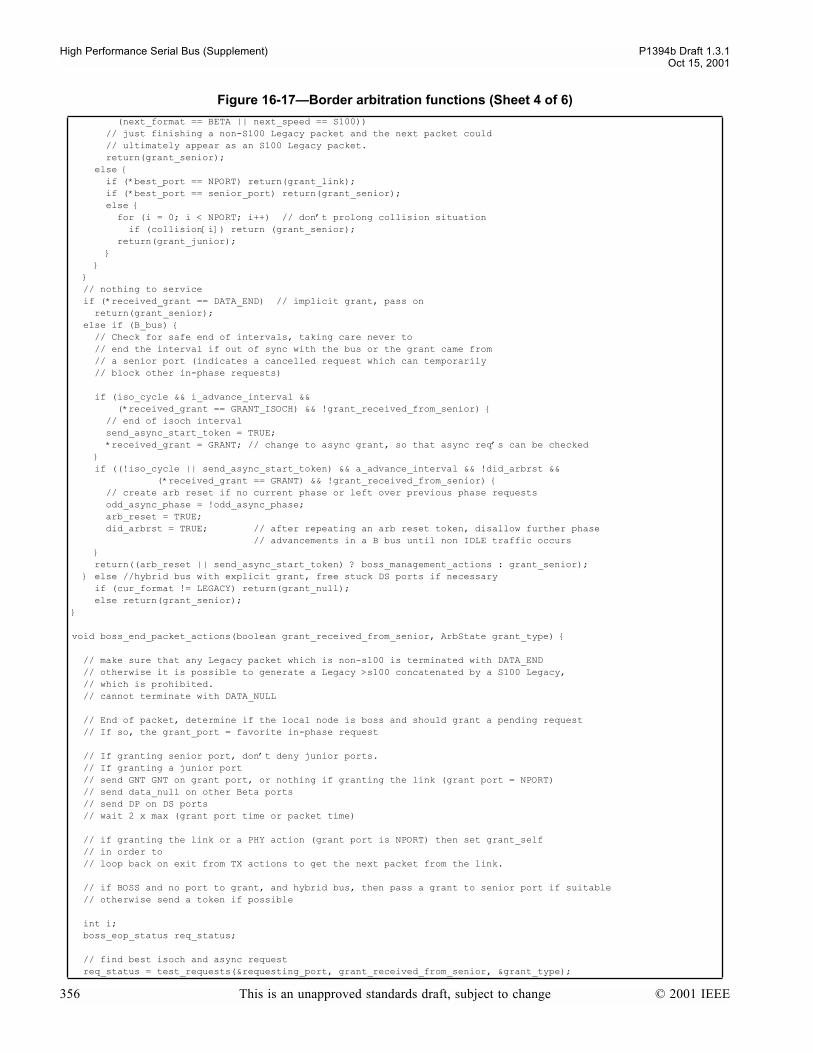
High Performance Serial Bus (Supplement) P1394b Draft 1.3.1Oct 15, 2001
(next_format == BETA || next_speed == S100)) // just finishing a non-S100 Legacy packet and the next packet could // ultimately appear as an S100 Legacy packet. return(grant_senior); else if (*best_port == NPORT) return(grant_link); if (*best_port == senior_port) return(grant_senior); else for (i = 0; i < NPORT; i++) // dont prolong collision situation if (collision[i]) return (grant_senior); return(grant_junior); // nothing to service if (*received_grant == DATA_END) // implicit grant, pass on return(grant_senior); else if (B_bus) // Check for safe end of intervals, taking care never to // end the interval if out of sync with the bus or the grant came from // a senior port (indicates a cancelled request which can temporarily // block other in-phase requests)
if (iso_cycle && i_advance_interval && (*received_grant == GRANT_ISOCH) && !grant_received_from_senior) // end of isoch interval send_async_start_token = TRUE; *received_grant = GRANT; // change to async grant, so that async reqs can be checked if ((!iso_cycle || send_async_start_token) && a_advance_interval && !did_arbrst && (*received_grant == GRANT) && !grant_received_from_senior) // create arb reset if no current phase or left over previous phase requests odd_async_phase = !odd_async_phase; arb_reset = TRUE; did_arbrst = TRUE; // after repeating an arb reset token, disallow further phase // advancements in a B bus until non IDLE traffic occurs return((arb_reset || send_async_start_token) ? boss_management_actions : grant_senior); else //hybrid bus with explicit grant, free stuck DS ports if necessary if (cur_format != LEGACY) return(grant_null); else return(grant_senior);
void boss_end_packet_actions(boolean grant_received_from_senior, ArbState grant_type)
// make sure that any Legacy packet which is non-s100 is terminated with DATA_END // otherwise it is possible to generate a Legacy >s100 concatenated by a S100 Legacy, // which is prohibited. // cannot terminate with DATA_NULL
// End of packet, determine if the local node is boss and should grant a pending request // If so, the grant_port = favorite in-phase request // If granting senior port, dont deny junior ports. // If granting a junior port // send GNT GNT on grant port, or nothing if granting the link (grant port = NPORT) // send data_null on other Beta ports // send DP on DS ports // wait 2 x max (grant port time or packet time)
// if granting the link or a PHY action (grant port is NPORT) then set grant_self // in order to // loop back on exit from TX actions to get the next packet from the link. // if BOSS and no port to grant, and hybrid bus, then pass a grant to senior port if suitable // otherwise send a token if possible
int i; boss_eop_status req_status;
// find best isoch and async request req_status = test_requests(&requesting_port, grant_received_from_senior, &grant_type);
Figure 16-17Border arbitration functions (Sheet 4 of 6)
356 This is an unapproved standards draft, subject to change © 2001 IEEE

P1394b Draft 1.3.1 High Performance Serial Bus (Supplement)Oct 15, 2001
switch (req_status) case grant_senior: if (grant_received_from_senior) // cant grant back to senior, stop_tx_packet(grant_type, NPORT); // so grant self and send_null_packet = TRUE; // schedule TX of a null packet grant_self = TRUE; else stop_tx_packet(grant_type, senior_port); requesting_port = NPORT;
// Set OK_to_grant for proxy_roots use in A0:Idle if end of subaction detected // and the grant type communicated matches the local PHYs interval (async vs isoch) // Special care is taken at the cycle master if attached to a Legacy link to ensure // that a priority bus request for the cycle start packet can be issued if required if (((grant_type == GRANT_ISOCH) && iso_cycle) || ((grant_type == GRANT) && !iso_cycle)) // explicit grant received which matches PHYs interval if (root && (link == Legacy_Link)) // await possible PriReq for cycle start OK_to_grant = FALSE; defer_grant = TRUE; else // explicit end of subaction, no need to defer grant in A0:Idle OK_to_grant = TRUE; defer_grant = FALSE; else // still expecting end of subaction or non-matching grant type OK_to_grant = FALSE; defer_grant = FALSE; return; case grant_link: stop_tx_packet(grant_type, NPORT); grant_to_give = grant_type; grant_self = TRUE; return; case grant_null: stop_tx_packet(grant_type, NPORT); send_null_packet = TRUE; // schedule TX of a null packet grant_self = TRUE; return; case grant_junior: stop_tx_packet(grant_type, requesting_port); grant_to_give = grant_type; return; case boss_management_actions: stop_tx_packet(grant_type, NPORT); gap_repeat_actions(NPORT); // having advanced the gap, now look for a favorite request again grant_type = GRANT; req_status = test_requests(&requesting_port, grant_received_from_senior, &grant_type); switch (req_status) case grant_senior: for (i = 0; i < NPORT; i++) if (i != senior_port) portTarb(i, IDLE); // while snr port gets GRANT if (!proxy_root) portTarb(senior_port, GRANT); wait_symbol_time(port_speed[senior_port]); wait_symbol_time(port_speed[senior_port]); OK_to_grant = TRUE; // for proxy_roots use in A0:Idle defer_grant = FALSE; requesting_port = NPORT; // so that node goes to Idle return; case grant_link: grant_to_give = grant_type; grant_self = TRUE; did_arbrst = FALSE; // only relevant to a B_bus return; case grant_null: send_null_packet = TRUE; // schedule TX of a null packet grant_self = TRUE; did_arbrst = FALSE; // only relevant to a B_bus return;
Figure 16-17Border arbitration functions (Sheet 5 of 6)
© 2001 IEEE This is an unapproved standards draft, subject to change 357
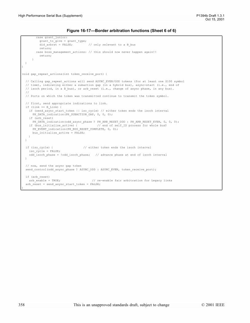
High Performance Serial Bus (Supplement) P1394b Draft 1.3.1Oct 15, 2001
case grant_junior: grant_to_give = grant_type; did_arbrst = FALSE; // only relevant to a B_bus return; case boss_management_actions: // this should now never happen again!! return;
void gap_repeat_actions(int token_receive_port)
// Calling gap_repeat_actions will send ASYNC_EVEN/ODD tokens (for at least one S100 symbol // time), indicating either a subaction gap (in a hybrid bus), async-start (i.e., end of // isoch period, in a B_bus), or arb_reset (i.e., change of async phase, in any bus). // // Ports on which the token was transmitted continue to transmit the token symbol.
// first, send appropriate indications to link. if (link == B_Link) if (send_async_start_token || iso_cycle) // either token ends the isoch interval PH_DATA_indication(PH_SUBACTION_GAP, 0, 0, 0); if (arb_reset) PH_DATA_indication(odd_async_phase ? PH_ARB_RESET_ODD : PH_ARB_RESET_EVEN, 0, 0, 0); if (bus_initialize_active) // end of self_ID process for whole bus? PH_EVENT_indication(PH_BUS_RESET_COMPLETE, 0, 0); bus_initialize_active = FALSE; if (iso_cycle) // either token ends the isoch interval iso_cycle = FALSE; odd_isoch_phase = !odd_isoch_phase; // advance phase at end of isoch interval // now, send the async gap token send_control(odd_async_phase ? ASYNC_ODD : ASYNC_EVEN, token_receive_port); if (arb_reset) arb_enable = TRUE; // re-enable fair arbitration for Legacy links arb_reset = send_async_start_token = FALSE;
Figure 16-17Border arbitration functions (Sheet 6 of 6)
358 This is an unapproved standards draft, subject to change © 2001 IEEE
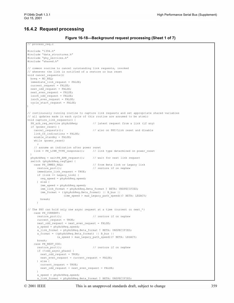
P1394b Draft 1.3.1 High Performance Serial Bus (Supplement)Oct 15, 2001
16.4.2 Request processing
Figure 16-18Background request processing (Sheet 1 of 7)
// process_req.c
#include 1394.h#include data_structures.h#include phy_services.h#include shared.h
// common routine to cancel outstanding link requests, invoked// whenever the link is notified of a restore or bus resetvoid cancel_requests() breq = NO_REQ; immediate_link_request = FALSE; current_request = FALSE; next_odd_request = FALSE; next_even_request = FALSE; isoch_odd_request = FALSE; isoch_even_request = FALSE; cycle_start_request = FALSE;
// continuously running routine to capture link requests and set appropriate shared variables// all updates made in each cycle of this routine are assumed to be atomicvoid capture_link_requests() PH_arb_req_service phyArbReq; // latest request from a link (if any) if (power_reset) cancel_requests(); // also on PHY/Link reset and disable link_CS_indications = FALSE; enable_standby = FALSE; while (power_reset) ; // assume an indication after power reset link = PH_LINK_TYPE_response(); // link type determined on power_reset phyArbReq = waitPH_ARB_request(); // wait for next link request switch (phyArbReq.reqType) case PH_IMMED_REQ: // from Beta link or Legacy link restore_port(); // restore if on nephew immediate_link_request = TRUE; if (link == Legacy_Link) req_speed = phyArbReq.speed; else imm_speed = phyArbReq.speed; imm_link_format = phyArbReq.Beta_format ? BETA: UNSPECIFIED; imm_format = ((phyArbReq.Beta_format) || B_bus || (imm_speed > max_Legacy_path_speed))? BETA: LEGACY; break; // The PHY can hold only one async request at a time (current or next_*) case PH_CURRENT: restore_port(); // restore if on nephew current_request = TRUE; next_odd_request = next_even_request = FALSE; a_speed = phyArbReq.speed; a_link_format = phyArbReq.Beta_format ? BETA: UNSPECIFIED; a_format = ((phyArbReq.Beta_format) || B_bus || (a_speed > max_Legacy_path_speed))? BETA: LEGACY; break; case PH_NEXT_ODD: restore_port(); // restore if on nephew if (!odd_async_phase) next_odd_request = TRUE; next_even_request = current_request = FALSE; else current_request = TRUE; next_odd_request = next_even_request = FALSE; a_speed = phyArbReq.speed; a_link_format = phyArbReq.Beta_format ? BETA: UNSPECIFIED;
© 2001 IEEE This is an unapproved standards draft, subject to change 359

High Performance Serial Bus (Supplement) P1394b Draft 1.3.1Oct 15, 2001
a_format = ((phyArbReq.Beta_format) || B_bus || (a_speed > max_Legacy_path_speed))? BETA: LEGACY; break; case PH_NEXT_EVEN: restore_port(); // restore if on nephew if (odd_async_phase) next_even_request = TRUE; next_odd_request = current_request = FALSE; else current_request = TRUE; next_odd_request = next_even_request = FALSE; a_speed = phyArbReq.speed; a_link_format = phyArbReq.Beta_format ? BETA: UNSPECIFIED; a_format = ((phyArbReq.Beta_format) || B_bus || (a_speed > max_Legacy_path_speed))? BETA: LEGACY; break; case PH_CYC_START_REQ: // to send a cycle start packet, preceded by a cycle_start_token // Note that cycle start requests are the only bus requests from a beta link // that are queued after a bus reset or restore before the register 0 transfer restore_port(); // restore if on nephew cycle_start_request = TRUE; cyc_start_speed = phyArbReq.speed; cyc_start_link_format = phyArbReq.Beta_format ? BETA: UNSPECIFIED; cyc_start_format = ((phyArbReq.Beta_format) || B_bus || (cyc_start_speed > max_Legacy_path_speed))? BETA: LEGACY; break; case PH_ISOCH_REQ_EVEN: restore_port(); // restore if on nephew isoch_even_request = TRUE; isoch_odd_request = FALSE; i_speed = phyArbReq.speed; i_link_format = phyArbReq.Beta_format ? BETA: UNSPECIFIED; i_format = ((phyArbReq.Beta_format) || B_bus || (i_speed > max_Legacy_path_speed))? BETA: LEGACY; break; case PH_ISOCH_REQ_ODD: restore_port(); // restore if on nephew isoch_odd_request = TRUE; isoch_even_request = FALSE; i_speed = phyArbReq.speed; i_link_format = phyArbReq.Beta_format ? BETA: UNSPECIFIED; i_format = ((phyArbReq.Beta_format) || B_bus || (i_speed > max_Legacy_path_speed))? BETA: LEGACY; break; case PH_ISOCH_PHASE_ODD: // link has received a cycle start packet odd_isoch_phase = TRUE; // keeps link and PHY in phase in junior beta clouds iso_cycle = TRUE; // in case cycle start token wasnt received accelerating = TRUE; break; case PH_ISOCH_PHASE_EVEN: // link has received a cycle start packet odd_isoch_phase = FALSE; // keeps link and PHY in phase in junior beta clouds iso_cycle = TRUE; // in case cycle start token wasnt received accelerating = TRUE; break; case PH_LPS_ACTIVE: LPS = TRUE; if (enable_standby) enable_standby = FALSE; restore_port(); break; case PH_LPS_INACTIVE: LPS = FALSE; cancel_requests(); link_CS_indications = FALSE; break; case PH_CYCLE_START_DUE: link_CS_indications = TRUE; accelerating = FALSE; break;
Figure 16-18Background request processing (Sheet 2 of 7)
360 This is an unapproved standards draft, subject to change © 2001 IEEE

P1394b Draft 1.3.1 High Performance Serial Bus (Supplement)Oct 15, 2001
// finally requests from a Legacy link case PH_CYCLE_START_SEEN: accelerating = TRUE; break; case PH_ISOCH_REQ: accelerating = TRUE; breq = ISOCH_REQ; req_speed = phyArbReq.speed; break; case PH_PRIORITY_REQ: breq = PRIORITY_REQ; req_speed = phyArbReq.speed; break; case PH_FAIR_REQ: breq = FAIR_REQ; req_speed = phyArbReq.speed; break;
// continuously running routine to process request signals received on Beta ports and linkvoid process_requests() boolean idle_arb_state_timeout; // TRUE if node has an ungranted request from the link or // local PHY, see description of Arb state timeout in text BetaRequestCode best_req; byte apm, ipm; int bip, bap; // best isoch and async ports portSymbol portCurrent; boolean in_packet[NPORT]; boolean ignore_port[NPORT]; // TRUE if temporarily ignoring a packet from a port due to // a collision (packet received while already receiving a packet) int i,j; if (power_reset) for (i = 0; i < NPORT; i++) advance_OK[i] = TRUE; in_packet[i] = FALSE; ignore_port[i] = FALSE; collision[i] = FALSE; fifo_rd_ptr[i] = 0; while (power_reset) ; // update own_req with request from link or internal PHY request // set own async req
immediate_request = immediate_link_request || immediate_phy_request || immediate_restore_request; if ((senior_border) && // the timer only runs on the senior border (max_beta_timer > MAX_BETA_TIME) && DS_stuck) own_req.async = BORDER; else if (cycle_start_request && root) own_req.async = CYCLE_START_REQ; else if (current_request || (restore_request && !immediate_restore_request) || loop_test_request || isbr) // connection management requests for restoring and loop free build // as well as short bus reset requests look like current requests own_req.async = CURRENT; else if (next_odd_request) // previously checked for async phase own_req.async = NEXT_ODD; else if (next_even_request) own_req.async = NEXT_EVEN; else if (odd_async_phase) own_req.async = NONE_ODD; else own_req.async = NONE_EVEN; // Set own isoch req remembering to upgrade any in-phase isoch request to // ISOCH_CURRENT during the isochronous interval. Also, only ISOCH_CURRENT and // ISOCH_NONE are allowed in junior beta clouds.
Figure 16-18Background request processing (Sheet 3 of 7)
© 2001 IEEE This is an unapproved standards draft, subject to change 361

High Performance Serial Bus (Supplement) P1394b Draft 1.3.1Oct 15, 2001
if (iso_cycle && ((isoch_odd_request && odd_isoch_phase) || // in-phase odd request? (isoch_even_request && !odd_isoch_phase))) // in-phase even request? own_req.isoch = ISOCH_CURRENT; else if (B_node_root && isoch_odd_request) own_req.isoch = ISOCH_ODD; // never present in junior beta cloud else if (B_node_root && isoch_even_request) own_req.isoch = ISOCH_EVEN; // never present in junior beta cloud else own_req.isoch = ISOCH_NONE;
idle_arb_state_timeout = (!((own_req.async == NONE_ODD || own_req.async == NONE_EVEN) && own_req.isoch == ISOCH_NONE)); // link or local PHY is requesting, so ensure that // Arbitration state timeout occurs when in Idle for MAX_ARB_STATE_TIME after this is set TRUE // gather incoming requests from ports, remember/forget past requests // set flags, portRarb and portRspeed for (i = 0; i < NPORT; i++)
// check for collisions, given that only the receive_port should be in_packet for receive states, // and no ports should be in_packet for transmit, bus reset, and tree ID states if (active[i] && in_packet[i] && (((PHY_state == RX) && (receive_port != i)) || ((PHY_state == S2) && (receive_port != i)) || (PHY_state == TX) || (PHY_state == PH) || (PHY_state == S4) || (PHY_state < S0))) collision[i] = TRUE; // data collision, need to keep the rest of the bus // busy until this packet completes ignore_port[i] = TRUE; // flag to ignore the rest of the packet portRarb[i] = IDLE; // clear colliding arbitration state in_packet[i] = FALSE; // allow fifo to dequeue automatically // invalidate stale GRANTs and LEGACY_REQUESTs if (active[i] && ((portRarb[i] == GRANT) || (portRarb[i] == GRANT_ISOCH) || (portRarb[i] == LEGACY_REQUEST)) && ((PHY_state == TX) || (PHY_state == RX) || (PHY_state == PH)) && (receive_port != i)) // necessary to protect GRANTs at end of packets portRarb[i] = IDLE; if ( (!(active[i] || restore[i]) || // always dequeue the fifo unless in active or restore !in_packet[i] || advance_OK[i])) if (packet_ending[i]) in_packet[i] = FALSE; // last symbol terminated a packet ignore_port[i] = FALSE; // no longer need to ignore packet_ending[i] = FALSE; // and with the new arb state, now past the end of the packet
// OK to process next item, if theres anything to process! if (fifo_rd_ptr[i] != fifo_wr_ptr[i]) fifo_rd_ptr[i] = ++fifo_rd_ptr[i] % FIFO_DEPTH; portCurrent = portR[i][fifo_rd_ptr[i]]; advance_OK[i] = FALSE; if (portCurrent.tag == DS_RAW_ARB) // Raw arb states received from a Legacy port require filtering to resolve many of the // overloaded states. This segment of code illustrates use of the current PHY state // to perform the filtering and is not intended to preclude alternate methods portCurrent.tag = ARB_STATE; switch (portCurrent.rx_dsarb) case RX_IDLE : portCurrent.arb = IDLE; break; case RX_PARENT_NOTIFY | RX_REQUEST_CANCEL : portCurrent.arb = (PHY_state < A0 ? PARENT_NOTIFY : REQUEST_CANCEL); break; case RX_IDENT_DONE : portCurrent.arb = IDENT_DONE; break; case RX_SELF_ID_GRANT | RX_REQUEST : portCurrent.arb = (PHY_state < A0 ? SELF_ID_GRANT : LEGACY_REQUEST); break;
Figure 16-18Background request processing (Sheet 4 of 7)
362 This is an unapproved standards draft, subject to change © 2001 IEEE
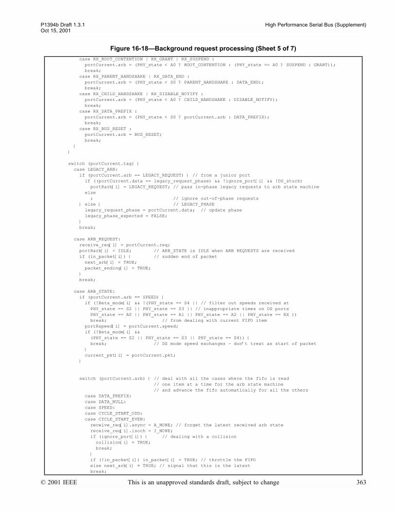
P1394b Draft 1.3.1 High Performance Serial Bus (Supplement)Oct 15, 2001
case RX_ROOT_CONTENTION | RX_GRANT | RX_SUSPEND : portCurrent.arb = (PHY_state < A0 ? ROOT_CONTENTION : (PHY_state == A0 ? SUSPEND : GRANT)); break; case RX_PARENT_HANDSHAKE | RX_DATA_END : portCurrent.arb = (PHY_state < S0 ? PARENT_HANDSHAKE : DATA_END); break; case RX_CHILD_HANDSHAKE | RX_DISABLE_NOTIFY : portCurrent.arb = (PHY_state < A0 ? CHILD_HANDSHAKE : DISABLE_NOTIFY); break; case RX_DATA_PREFIX : portCurrent.arb = (PHY_state < S0 ? portCurrent.arb : DATA_PREFIX); break; case RX_BUS_RESET : portCurrent.arb = BUS_RESET; break; switch (portCurrent.tag) case LEGACY_ARB: if (portCurrent.arb == LEGACY_REQUEST) // from a junior port if ((portCurrent.data == legacy_request_phase) && !ignore_port[i] && !DS_stuck) portRarb[i] = LEGACY_REQUEST; // pass in-phase legacy requests to arb state machine else ; // ignore out-of-phase requests else // LEGACY_PHASE legacy_request_phase = portCurrent.data; // update phase legacy_phase_expected = FALSE; break; case ARB_REQUEST: receive_req[i] = portCurrent.req; portRarb[i] = IDLE; // ARB_STATE is IDLE when ARB REQUESTS are received if (in_packet[i]) // sudden end of packet next_arb[i] = TRUE; packet_ending[i] = TRUE; break; case ARB_STATE: if (portCurrent.arb == SPEED) if (!Beta_mode[i] && !(PHY_state == S4 || // filter out speeds received at PHY_state == S2 || PHY_state == S3 || // inappropriate times on DS ports PHY_state == A0 || PHY_state == A1 || PHY_state == A2 || PHY_state == RX )) break; // from dealing with current FIFO item portRspeed[i] = portCurrent.speed; if (!Beta_mode[i] && (PHY_state == S2 || PHY_state == S3 || PHY_state == S4)) break; // DS mode speed exchanges - dont treat as start of packet current_pkt[i] = portCurrent.pkt;
switch (portCurrent.arb) // deal with all the cases where the fifo is read // one item at a time for the arb state machine // and advance the fifo automatically for all the others case DATA_PREFIX: case DATA_NULL: case SPEED: case CYCLE_START_ODD: case CYCLE_START_EVEN: receive_req[i].async = A_NONE; // forget the latest received arb state receive_req[i].isoch = I_NONE; if (ignore_port[i]) // dealing with a collision collision[i] = TRUE; break; if (!in_packet[i]) in_packet[i] = TRUE; // throttle the FIFO else next_arb[i] = TRUE; // signal that this is the latest break;
Figure 16-18Background request processing (Sheet 5 of 7)
© 2001 IEEE This is an unapproved standards draft, subject to change 363

High Performance Serial Bus (Supplement) P1394b Draft 1.3.1Oct 15, 2001
case GRANT: // may terminate a packet or occur in isolation case GRANT_ISOCH: // may terminate a packet or occur in isolation if (ignore_port[i]) // dealing with a collision collision[i] = TRUE; break; if (in_packet[i]) next_arb[i] = TRUE; packet_ending[i] = TRUE; break; case DATA_END: if (ignore_port[i]) // dealing with a collision collision[i] = TRUE; packet_ending[i] = TRUE; break; next_arb[i] = TRUE; packet_ending[i] = TRUE; break; case IDLE: // may also cause sudden packet termination case BUS_RESET: case ARB_CONTEXT: receive_req[i].async = A_NONE; // forget the latest received arb state receive_req[i].isoch = I_NONE; if (in_packet[i]) next_arb[i] = TRUE; packet_ending[i] = TRUE; portRspeed[i] = S100; // and erase memory of speed signal break; case ASYNC_EVEN: case ASYNC_ODD: if (ignore_port[i]) // dealing with a collision collision[i] = TRUE; break; if (in_packet[i]) next_arb[i] = TRUE; break; if (!ignore_port[i]) portRarb[i] = portCurrent.arb; // set the current arb state break; // finished dealing with ARB states case DATA: if (ignore_port[i]) // dealing with a collision collision[i] = TRUE; break; current_data[i] = portCurrent.data; portRarb[i] = DATA_BYTE; next_arb[i] = TRUE; portRspeed[i] = S100; // and erase memory of speed signal break; // end of dealing with the latest in the fifo //combine best async and isoch request from other ports and own request if (active[i] && Beta_mode[i]) best_req.async = own_req.async; // prefer link first best_req.isoch = own_req.isoch; apm = (odd_async_phase ? 0xf0 : 0x0f); // select async priority mask ipm = (odd_isoch_phase ? 0xf0 : 0x0f); // select isoch priority mask bip = bap = NPORT; for (j = 0; j < NPORT; j++) // then prefer junior ports if (j != i && (j != senior_port)) // careful to avoid requests on a restoring port best_req.async = active[j] && Beta_mode[j] && ((receive_req[j].async & apm) > (best_req.async & apm)) ? receive_req[bap = j].async : best_req.async; best_req.isoch = active[j] && Beta_mode[j] &&
Figure 16-18Background request processing (Sheet 6 of 7)
364 This is an unapproved standards draft, subject to change © 2001 IEEE
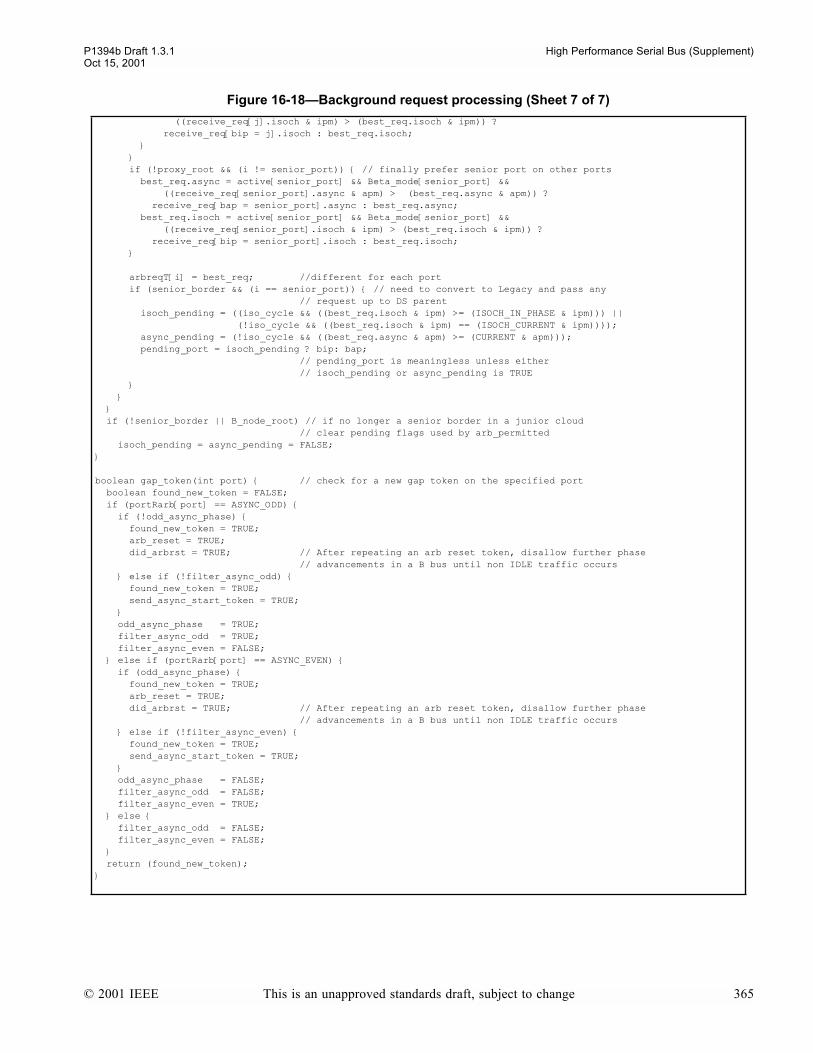
P1394b Draft 1.3.1 High Performance Serial Bus (Supplement)Oct 15, 2001
((receive_req[j].isoch & ipm) > (best_req.isoch & ipm)) ? receive_req[bip = j].isoch : best_req.isoch; if (!proxy_root && (i != senior_port)) // finally prefer senior port on other ports best_req.async = active[senior_port] && Beta_mode[senior_port] && ((receive_req[senior_port].async & apm) > (best_req.async & apm)) ? receive_req[bap = senior_port].async : best_req.async; best_req.isoch = active[senior_port] && Beta_mode[senior_port] && ((receive_req[senior_port].isoch & ipm) > (best_req.isoch & ipm)) ? receive_req[bip = senior_port].isoch : best_req.isoch; arbreqT[i] = best_req; //different for each port if (senior_border && (i == senior_port)) // need to convert to Legacy and pass any // request up to DS parent isoch_pending = ((iso_cycle && ((best_req.isoch & ipm) >= (ISOCH_IN_PHASE & ipm))) || (!iso_cycle && ((best_req.isoch & ipm) == (ISOCH_CURRENT & ipm)))); async_pending = (!iso_cycle && ((best_req.async & apm) >= (CURRENT & apm))); pending_port = isoch_pending ? bip: bap; // pending_port is meaningless unless either // isoch_pending or async_pending is TRUE if (!senior_border || B_node_root) // if no longer a senior border in a junior cloud // clear pending flags used by arb_permitted isoch_pending = async_pending = FALSE;
boolean gap_token(int port) // check for a new gap token on the specified port boolean found_new_token = FALSE; if (portRarb[port] == ASYNC_ODD) if (!odd_async_phase) found_new_token = TRUE; arb_reset = TRUE; did_arbrst = TRUE; // After repeating an arb reset token, disallow further phase // advancements in a B bus until non IDLE traffic occurs else if (!filter_async_odd) found_new_token = TRUE; send_async_start_token = TRUE; odd_async_phase = TRUE; filter_async_odd = TRUE; filter_async_even = FALSE; else if (portRarb[port] == ASYNC_EVEN) if (odd_async_phase) found_new_token = TRUE; arb_reset = TRUE; did_arbrst = TRUE; // After repeating an arb reset token, disallow further phase // advancements in a B bus until non IDLE traffic occurs else if (!filter_async_even) found_new_token = TRUE; send_async_start_token = TRUE; odd_async_phase = FALSE; filter_async_odd = FALSE; filter_async_even = TRUE; else filter_async_odd = FALSE; filter_async_even = FALSE; return (found_new_token);
Figure 16-18Background request processing (Sheet 7 of 7)
© 2001 IEEE This is an unapproved standards draft, subject to change 365

High Performance Serial Bus (Supplement) P1394b Draft 1.3.1Oct 15, 2001
16.4.3 Bus reset
Figure 16-19Reset actions (Sheet 1 of 3)
// reset.c
#include 1394.h#include data_structures.h#include phy_services.h#include arb.h#include shared.h
void arb_power_reset() arb_reset = FALSE; accelerating = TRUE; initiated_reset = TRUE; reset_duration = RESET_TIME; loop_to_detect = FALSE; bus_initialize_active = FALSE; restore_request = FALSE; immediate_phy_request = immediate_restore_request = FALSE; time_out_of_idle = 0; // misc registers in the PHY reg map gap_count_reset_disable = ibr = isbr = loop = Timeout = FALSE; while (power_reset) ; PH_EVENT_indication(PH_LINK_ON, 0, 0); // only for power classes 0-4 // for a min of 166 usecs (16384 PClk cycles). // see Clause 14.4 for full requirements
boolean reset_detected() // Qualify BUS_RESET with port status / history int i; if ( PHY_state == R0 || PHY_state == R1 // Ignore during (or just before) reset... || isbr_OK || phy_response) // ...or if busy with a PHY command return(FALSE); for (i = 0; i < NPORT; i++) if (disabled[i]) // Ignore completely if disabled continue; else if ((Beta_mode[i] || bias[i]) && (portRarb[i] == BUS_RESET)) if (active[i]) reset_duration = (PHY_state == RX) ? SHORT_RESET_TIME : RESET_TIME; return(TRUE); else if (resume[i] && OK_to_detect_reset && !bus_initialize_active) resumption_done = TRUE; reset_duration = (boundary_node) ? RESET_TIME : SHORT_RESET_TIME; return(TRUE); else if (attach[i] && ((NPORT==1) || ((i == test_port) && send_attach))) reset_duration = SHORT_RESET_TIME; // Found a reset returned in response to // an ATTACH_REQUEST issued, so attempt a // short reset. Note well: this should only // test true on a single port phy or an // isolated node as any other node retains // control of the bus while awaiting the // return reset return(TRUE); return(FALSE);
void reset_start_actions() // Transmit BUS_RESET for reset_duration on all ports int i;
if (!bus_initialize_active) bus_initialize_active = TRUE; if (gap_count_reset_disable) // First reset since setting gap_count? gap_count_reset_disable = FALSE; // If so, leave it as is and arm it for next else gap_count = 0x3F; // Otherwise, set it to the maximum if (isolated_node) force_root = FALSE; // No point in waiting to become root if isolated
366 This is an unapproved standards draft, subject to change © 2001 IEEE
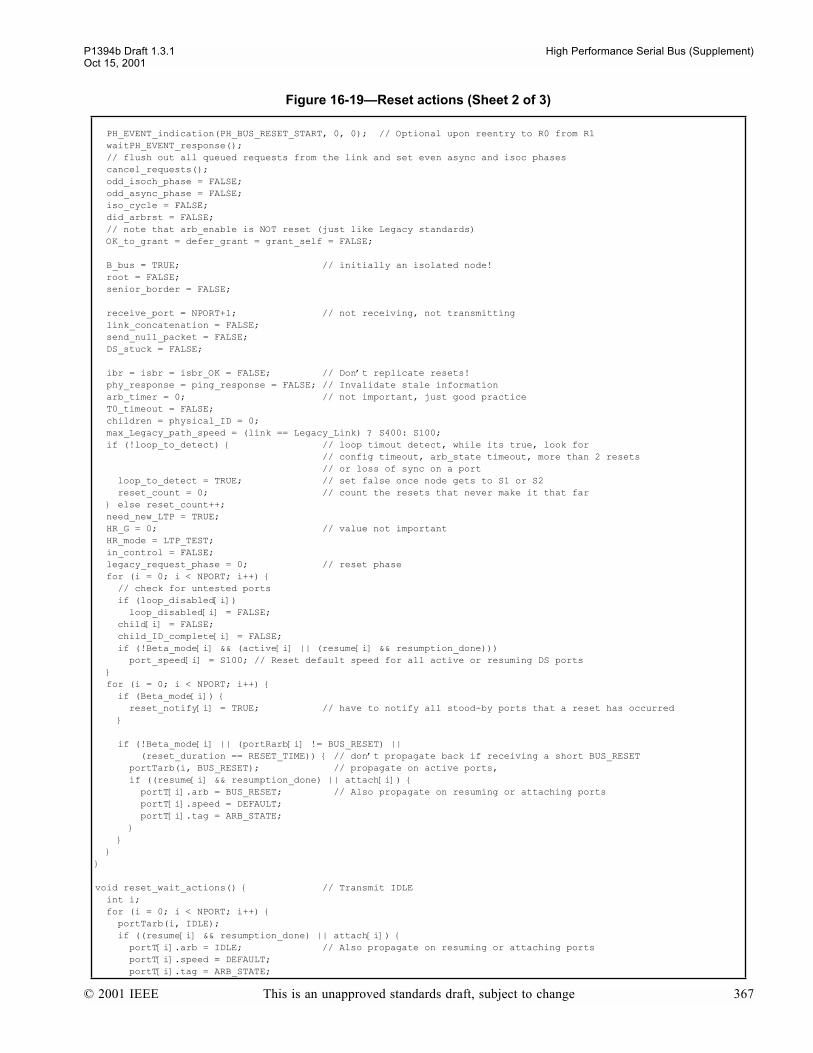
P1394b Draft 1.3.1 High Performance Serial Bus (Supplement)Oct 15, 2001
PH_EVENT_indication(PH_BUS_RESET_START, 0, 0); // Optional upon reentry to R0 from R1 waitPH_EVENT_response(); // flush out all queued requests from the link and set even async and isoc phases cancel_requests(); odd_isoch_phase = FALSE; odd_async_phase = FALSE; iso_cycle = FALSE; did_arbrst = FALSE; // note that arb_enable is NOT reset (just like Legacy standards) OK_to_grant = defer_grant = grant_self = FALSE;
B_bus = TRUE; // initially an isolated node! root = FALSE; senior_border = FALSE; receive_port = NPORT+1; // not receiving, not transmitting link_concatenation = FALSE; send_null_packet = FALSE; DS_stuck = FALSE;
ibr = isbr = isbr_OK = FALSE; // Dont replicate resets! phy_response = ping_response = FALSE; // Invalidate stale information arb_timer = 0; // not important, just good practice T0_timeout = FALSE; children = physical_ID = 0; max_Legacy_path_speed = (link == Legacy_Link) ? S400: S100; if (!loop_to_detect) // loop timout detect, while its true, look for // config timeout, arb_state timeout, more than 2 resets // or loss of sync on a port loop_to_detect = TRUE; // set false once node gets to S1 or S2 reset_count = 0; // count the resets that never make it that far else reset_count++; need_new_LTP = TRUE; HR_G = 0; // value not important HR_mode = LTP_TEST; in_control = FALSE; legacy_request_phase = 0; // reset phase for (i = 0; i < NPORT; i++) // check for untested ports if (loop_disabled[i]) loop_disabled[i] = FALSE; child[i] = FALSE; child_ID_complete[i] = FALSE; if (!Beta_mode[i] && (active[i] || (resume[i] && resumption_done))) port_speed[i] = S100; // Reset default speed for all active or resuming DS ports for (i = 0; i < NPORT; i++) if (Beta_mode[i]) reset_notify[i] = TRUE; // have to notify all stood-by ports that a reset has occurred if (!Beta_mode[i] || (portRarb[i] != BUS_RESET) || (reset_duration == RESET_TIME)) // dont propagate back if receiving a short BUS_RESET portTarb(i, BUS_RESET); // propagate on active ports, if ((resume[i] && resumption_done) || attach[i]) portT[i].arb = BUS_RESET; // Also propagate on resuming or attaching ports portT[i].speed = DEFAULT; portT[i].tag = ARB_STATE;
void reset_wait_actions() // Transmit IDLE int i; for (i = 0; i < NPORT; i++) portTarb(i, IDLE); if ((resume[i] && resumption_done) || attach[i]) portT[i].arb = IDLE; // Also propagate on resuming or attaching ports portT[i].speed = DEFAULT; portT[i].tag = ARB_STATE;
Figure 16-19Reset actions (Sheet 2 of 3)
© 2001 IEEE This is an unapproved standards draft, subject to change 367
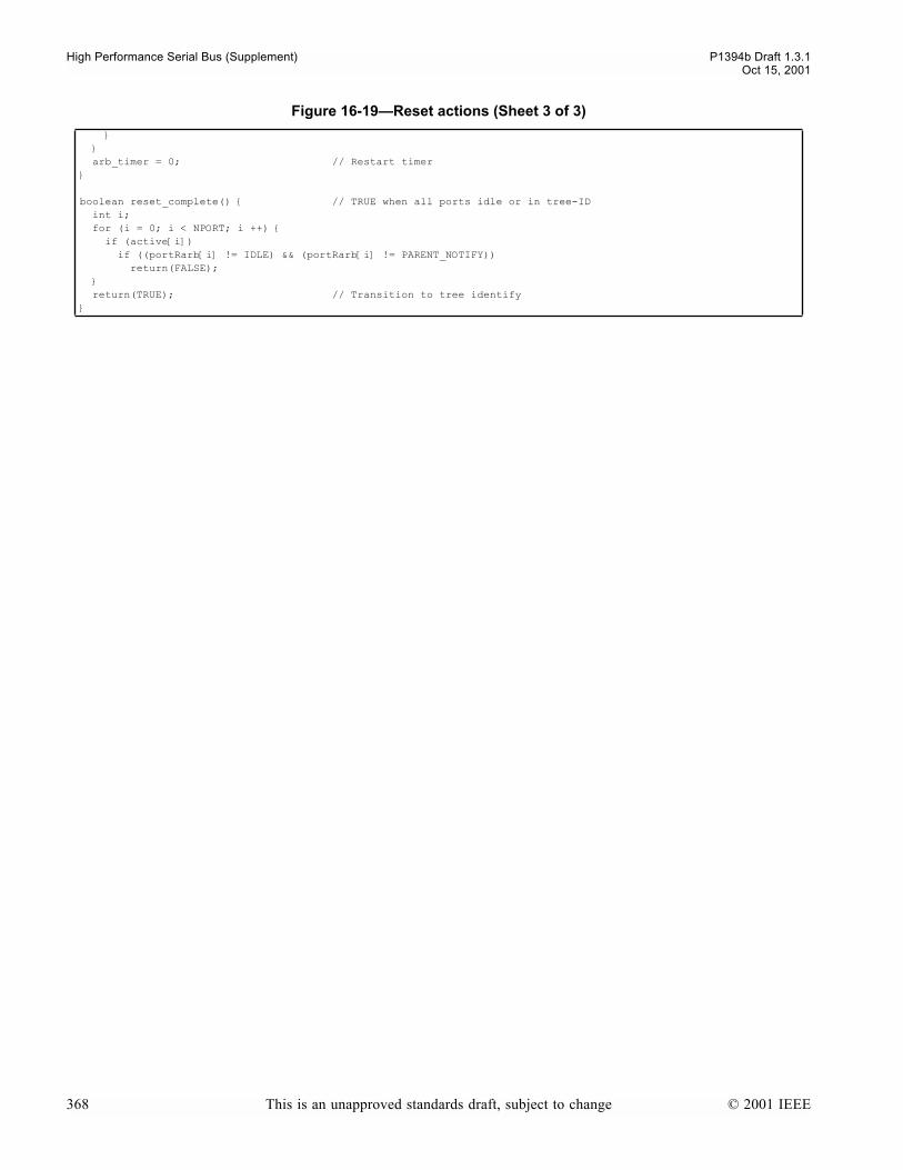
High Performance Serial Bus (Supplement) P1394b Draft 1.3.1Oct 15, 2001
arb_timer = 0; // Restart timer
boolean reset_complete() // TRUE when all ports idle or in tree-ID int i; for (i = 0; i < NPORT; i ++) if (active[i]) if ((portRarb[i] != IDLE) && (portRarb[i] != PARENT_NOTIFY)) return(FALSE); return(TRUE); // Transition to tree identify
Figure 16-19Reset actions (Sheet 3 of 3)
368 This is an unapproved standards draft, subject to change © 2001 IEEE

P1394b Draft 1.3.1 High Performance Serial Bus (Supplement)Oct 15, 2001
16.4.4 Tree ID
Figure 16-20Tree ID actions
// treeid.c
#include 1394.h#include data_structures.h#include phy_services.h#include arb.h#include shared.h
void tree_ID_start_actions() int i;
do children = 0; // Count the kids afresh on each loop for (i = 0; i < NPORT; i++) if (!active[i] || portRarb[i] == PARENT_NOTIFY) child[i] = TRUE; // Child if disabled, disconnected or suspended children++; // or if other PHY asks us to be the parent if (children == NPORT - 1 && (!force_root || arb_timer >= FORCE_ROOT_TIMEOUT)) return; // Only one port left as the parent else if (children == NPORT) return; // node is the root while (!(reset_detected() || ibr || isbr|| (!T0_timeout && (arb_timer == CONFIG_TIMEOUT))));
void child_handshake_actions() int i; senior_port = parent_port = NPORT+1; // No parent port (in case node becomes root) proxy_root = root = TRUE; // Remains TRUE if all the ports are child ports for (i = 0; i < NPORT; i++) if (active[i]) // Only the connected, active ports participate if (child[i]) portTarb(i, CHILD_NOTIFY); // Tell peer PHY, You are my child else portTarb(i, PARENT_NOTIFY); // Ask peer PHY, Please be my parent senior_port = parent_port = i; // Only one parent port possible proxy_root = root = FALSE; // Tentative---see root contention
boolean child_handshake_complete() // TRUE once all active children are in S0: Self ID Start int i; for (i = 0; i < NPORT; i++) if (active[i] && child[i] && !((portRarb[i] == CHILD_HANDSHAKE) || // DS ports (portRarb[i] == IDLE))) // Beta ports return(FALSE); // One as yet uncompleted handshake... return(TRUE); // All child ports have finished their handshakes
void root_contend_actions() int i; contend_time = (random_bool() ? ROOT_CONTEND_SLOW : ROOT_CONTEND_FAST); for (i = 0; i < NPORT; i++) if (child[i]) // Only the connected, active ports matter portTarb(i, CHILD_NOTIFY); // Continue to tell peer PHY, You are my child else portTarb(i, IDLE); // Withdraw Please be my parent request arb_timer = 0; // Restart arbitration timer
© 2001 IEEE This is an unapproved standards draft, subject to change 369
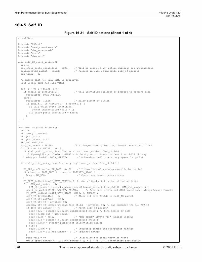
High Performance Serial Bus (Supplement) P1394b Draft 1.3.1Oct 15, 2001
16.4.5 Self_ID
Figure 16-21Self-ID actions (Sheet 1 of 4)
// selfid.c
#include 1394.h#include data_structures.h#include phy_services.h#include arb.h#include shared.h
void self_ID_start_actions() int i; all_child_ports_identified = TRUE; // Will be reset if any active children are unidentified concatenated_packet = FALSE; // Prepare in case of multiple self_ID packets arb_timer = 0;
// ensure that MIN_IDLE_TIME is preserved wait_Legacy_time(MIN_IDLE_TIME);
for (i = 0; i < NPORT; i++) if (child_ID_complete[i]) // Tell identified children to prepare to receive data portTarb(i, DATA_PREFIX); else portTarb(i, IDLE); // Allow parent to finish if (child[i] && (active[i] || proxy[i])) if (all_child_ports_identified) lowest_unidentified_child = i; all_child_ports_identified = FALSE;
void self_ID_grant_actions() int i; int SID_pkt_number; int port_stat; int port_number = 0; PHY_PKT self_ID; loop_to_detect = FALSE; // no longer looking for loop timeout detect conditions for (i = 0; i < NPORT; i++) if (!all_child_ports_identified && (i == lowest_unidentified_child)) if (!proxy[i]) portTarb(i, GRANT); // Send grant to lowest unidentified child (if any) else portTarb(i, DATA_PREFIX); // Otherwise, tell others to prepare for packet if (!all_child_ports_identified && proxy[lowest_unidentified_child])
PH_ARB_confirmation(PH_LOST, 0, 0); // Inform link of upcoming cancellation period if ((breq == FAIR_REQ) || (breq == PRIORITY_REQ)) breq = NO_REQ; // Cancel any asynchronous request PH_DATA_indication(PH_DATA_PREFIX, 0, 0, 0); // Send notification of bus activity for (SID_pkt_number = 0; SID_pkt_number < standby_packet_count[lowest_unidentified_child]; SID_pkt_number++) start_tx_packet(S100, LEGACY, FALSE); // Send data prefix and S100 speed code (always Legacy format) PH_DATA_indication(PH_DATA_START, S100, 0, LEGACY); self_ID.dataQuadlet = 0; // Clear all zero fields in self_ID packet self_ID.phy_pktType = 0b10; self_ID.phy_ID = physical_ID; standby_phy_ID[lowest_unidentified_child] = physical_ID; // and remember the new PHY_ID if (SID_pkt_number == 0) // First self ID packet? self_ID.L = standby_L[lowest_unidentified_child]; // Link active or not? self_ID.gap_cnt = gap_count; self_ID.sp = 0b11; // PHY_SPEED always 11 (unlike Legacy) self_ID.c = standby_c[lowest_unidentified_child]; self_ID.pwr = standby_pwr[lowest_unidentified_child]; else self_ID.ext = 1; // Indicates second and subsequent packets self_ID.n = SID_pkt_number - 1; // Sequence number port_stat = 0; // Initialize for fresh group of ports while (port_number < ((SID_pkt_number + 1) * 8 - 5)) // Concatenate port status
370 This is an unapproved standards draft, subject to change © 2001 IEEE

P1394b Draft 1.3.1 High Performance Serial Bus (Supplement)Oct 15, 2001
if (port_number >= standby_NPORT[lowest_unidentified_child]) ; // Unimplemented else if (standby_parent[lowest_unidentified_child] == port_number) port_stat |= 0b10; // Active parent else port_stat |= 0b01; // Disabled, disconnected or suspended port_number++; port_stat <<= 2; // Make room for next ports status self_ID.dataQuadlet |= port_stat; if (SID_pkt_number == standby_packet_count[lowest_unidentified_child] - 1) // Last packet? tx_quadlet(self_ID.dataQuadlet); tx_quadlet(~self_ID.dataQuadlet); // Yes, signal data end PH_DATA_indication(PH_DATA_END, 0, 0, 0); stop_tx_packet(DATA_END, NPORT); else self_ID.m = 1; // Other packets follow, set more bit tx_quadlet(self_ID.dataQuadlet); tx_quadlet(~self_ID.dataQuadlet); // Keep bus for concatenation PH_DATA_indication(PH_DATA_PREFIX, 0, 0, 0); stop_tx_packet(DATA_PREFIX, NPORT);
child_ID_complete[lowest_unidentified_child] = TRUE; if (physical_ID < 63) // Stop at 63 if malconfigured bus physical_ID = physical_ID + 1; // Otherwise, take next PHY address idle_receive_port = TRUE; // to exit back to self_ID start else idle_receive_port = FALSE;
void self_ID_receive_actions() int i; int SID_pkt_number = 0; int port_number = 0; int port_stat; boolean good_self_ID_sequence = TRUE; // until a bad phy packet is received arb_timer = 0; loop_to_detect = FALSE; // no longer looking for loop timeout detect conditions portTarb(receive_port, IDLE); // Turn off grant, get ready to receive do receive_actions(); // Receive (and repeat) packet if (good_phy_packet) if (SID_pkt_number == 0) // Only do this on the first self_ID packet // get the self ID info ready for restore from standby standby_phy_ID[receive_port] = self_ID_pkt.phy_ID; standby_L[receive_port] = self_ID_pkt.L; standby_c[receive_port] = self_ID_pkt.c; standby_pwr[receive_port] = self_ID_pkt.pwr; // find which port the peer is using as parent while (port_number < ((SID_pkt_number +1)*8 -5)) port_stat = (self_ID_pkt.dataQuadlet>>(((SID_pkt_number +1)*8 -5 -port_number)*2)) & 0b11; if (port_stat == 0b10) standby_parent[receive_port] = port_number; // TRUE exactly once port_number++; if (port_stat != 0b00) standby_NPORT[receive_port] = port_number; // eventually save the highest value else good_self_ID_sequence = FALSE; SID_pkt_number++; while (concatenated_packet); standby_packet_count[receive_port] = SID_pkt_number;
if (!good_self_ID_sequence) // construct substitute self_ID information for uncle to remember standby_phy_ID[receive_port] = 63;
Figure 16-21Self-ID actions (Sheet 2 of 4)
© 2001 IEEE This is an unapproved standards draft, subject to change 371
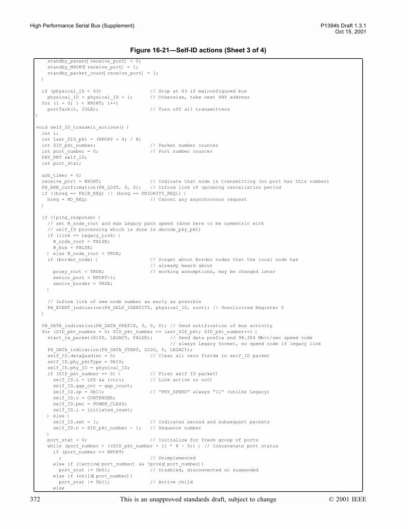
High Performance Serial Bus (Supplement) P1394b Draft 1.3.1Oct 15, 2001
standby_parent[receive_port] = 0; standby_NPORT[receive_port] = 1; standby_packet_count[receive_port] = 1;
if (physical_ID < 63) // Stop at 63 if malconfigured bus physical_ID = physical_ID + 1; // Otherwise, take next PHY address for (i = 0; i < NPORT; i++) portTarb(i, IDLE); // Turn off all transmitters
void self_ID_transmit_actions() int i; int last_SID_pkt = (NPORT + 4) / 8; int SID_pkt_number; // Packet number counter int port_number = 0; // Port number counter PHY_PKT self_ID; int port_stat;
arb_timer = 0; receive_port = NPORT; // Indicate that node is transmitting (no port has this number) PH_ARB_confirmation(PH_LOST, 0, 0); // Inform link of upcoming cancellation period if ((breq == FAIR_REQ) || (breq == PRIORITY_REQ)) breq = NO_REQ; // Cancel any asynchronous request
if (!ping_response) // set B_node_root and max Legacy path speed (done here to be symmetric with // self_ID processing which is done in decode_pky_pkt) if (link == Legacy_Link) B_node_root = FALSE; B_bus = FALSE; else B_node_root = TRUE; if (border_node) // forget about border nodes that the local node has // already heard about proxy_root = TRUE; // working assumptions, may be changed later senior_port = NPORT+1; senior_border = TRUE;
// Inform link of new node number as early as possible PH_EVENT_indication(PH_SELF_IDENTITY, physical_ID, root); // Unsolicited Register 0
PH_DATA_indication(PH_DATA_PREFIX, 0, 0, 0); // Send notification of bus activity for (SID_pkt_number = 0; SID_pkt_number <= last_SID_pkt; SID_pkt_number++) start_tx_packet(S100, LEGACY, FALSE); // Send data prefix and 98.304 Mbit/sec speed code // always Legacy format, no speed code if legacy link PH_DATA_indication(PH_DATA_START, S100, 0, LEGACY); self_ID.dataQuadlet = 0; // Clear all zero fields in self_ID packet self_ID.phy_pktType = 0b10; self_ID.phy_ID = physical_ID; if (SID_pkt_number == 0) // First self ID packet? self_ID.L = LPS && lctrl; // Link active or not? self_ID.gap_cnt = gap_count; self_ID.sp = 0b11; // PHY_SPEED always 11 (unlike Legacy) self_ID.c = CONTENDER; self_ID.pwr = POWER_CLASS; self_ID.i = initiated_reset; else self_ID.ext = 1; // Indicates second and subsequent packets self_ID.n = SID_pkt_number - 1; // Sequence number port_stat = 0; // Initialize for fresh group of ports while (port_number < ((SID_pkt_number + 1) * 8 - 5)) // Concatenate port status if (port_number >= NPORT) ; // Unimplemented else if (!active[port_number] && !proxy[port_number]) port_stat |= 0b01; // Disabled, disconnected or suspended else if (child[port_number]) port_stat |= 0b11; // Active child else
Figure 16-21Self-ID actions (Sheet 3 of 4)
372 This is an unapproved standards draft, subject to change © 2001 IEEE

P1394b Draft 1.3.1 High Performance Serial Bus (Supplement)Oct 15, 2001
port_stat |= 0b10; // Active parent port_number++; port_stat <<= 2; // Make room for next ports status self_ID.dataQuadlet |= port_stat; if (SID_pkt_number == last_SID_pkt) // Last packet? tx_quadlet(self_ID.dataQuadlet); tx_quadlet(~self_ID.dataQuadlet); // Yes, signal data end PH_DATA_indication(PH_DATA_END, 0, 0, 0); stop_tx_packet(DATA_END, NPORT); else self_ID.m = 1; // Other packets follow, set more bit tx_quadlet(self_ID.dataQuadlet); tx_quadlet(~self_ID.dataQuadlet); // Keep bus for concatenation PH_DATA_indication(PH_DATA_PREFIX, 0, 0, 0); stop_tx_packet(DATA_PREFIX, NPORT); if (!ping_response) // Skip if self_ID packet was in response to a ping for (i = 0; i < NPORT; i++) if (root || i != parent_port) portTarb(i, IDLE); // Turn off transmitters to children else // Notify parent that self_ID is complete and exhange speed portTarb_at_speed(i, IDENT_DONE, DS_port_speed[i]); if (!root) // If node has a parent... // Continue sending speed signal (if any) wait_Legacy_time(SPEED_SIGNAL_LENGTH); // Stop sending speed signal portTarb_at_speed(parent_port, IDENT_DONE, S100); if (root && B_bus) send_async_start_token = TRUE; // to get everyone in phase gap_repeat_actions(NPORT); OK_to_grant = TRUE; defer_grant = FALSE;
Figure 16-21Self-ID actions (Sheet 4 of 4)
© 2001 IEEE This is an unapproved standards draft, subject to change 373
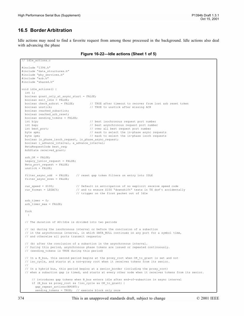
High Performance Serial Bus (Supplement) P1394b Draft 1.3.1Oct 15, 2001
16.5 Border Arbitration
Idle actions may need to find a favorite request from among those processed in the background. Idle actions also dealwith advancing the phase
Figure 16-22Idle actions (Sheet 1 of 5)
// idle_actions.c
#include 1394.h#include data_structures.h#include phy_services.h#include arb.h#include shared.h
void idle_actions() int i; boolean grant_only_at_async_start = FALSE; boolean exit_idle = FALSE; boolean check_arbrst = FALSE; // TRUE after timeout to recover from lost arb reset token boolean unstick; // TRUE to unstick after missing ACK boolean reached_subaction; boolean reached_arb_reset; boolean sending_tokens = FALSE; int bip; // best isochronous request port number int bap; // best asynchronous request port number int best_port; // over all best request port number byte apm; // mask to select the in-phase async requests byte ipm; // mask to select the in-phase isoch requests boolean in_phase_isoch_request, in_phase_async_request; boolean i_advance_interval, a_advance_interval; BetaRequestCode best_req; ArbState received_grant;
arb_OK = FALSE; Legacy_junior_request = FALSE; Beta_port_request = FALSE; unstick = FALSE;
filter_async_odd = FALSE; // reset gap token filters on entry into IDLE filter_async_even = FALSE;
cur_speed = S100; // Default in anticipation of no explicit receive speed code cur_format = LEGACY; // and to ensure S100 downshift tests in TX dont accidentally // trigger on the first packet out of Idle
arb_timer = 0; arb_timer_max = FALSE;
fork // The duration of A0:Idle is divided into two periods
// (a) during the isochronous interval or before the conclusion of a subaction // in the asynchronous interval, in which DATA_NULL continues on any port for a symbol time, // and otherwise all ports transmit requests;
// (b) after the conclusion of a subaction in the asynchronous interval. // During this period, asynchronous phase tokens are issued or repeated continuously. // (sending_tokens is TRUE during this period) // In a B_bus, this second period begins at the proxy_root when OK_to_grant is set and not // iso_cycle, and starts at a non-proxy root when it receives tokens from its senior. // // In a hybrid bus, this period begins at a senior_border (including the proxy_root) // when a subaction gap is timed, and starts at every other node when it receives tokens from its senior.
// introduces gap tokens when B_bus enters idle after end-of-subaction in async interval if (B_bus && proxy_root && !iso_cycle && OK_to_grant) gap_repeat_actions(NPORT); sending_tokens = TRUE; // execute block only once
374 This is an unapproved standards draft, subject to change © 2001 IEEE

P1394b Draft 1.3.1 High Performance Serial Bus (Supplement)Oct 15, 2001
do for (i = 0; i<NPORT; i++) // all ports default to sending the best arbitration request known, // except for DS stuck ports, until start sending tokens on junior ports // delay setting IDLE on a port if there has not been enough time out of idle // to send a single symbol on that port, and a remote node might need to see the // symbol in order to stop timing a gap if (!sending_tokens && (B_bus || !DS_stuck || (Beta_mode[i] && !(time_out_of_idle < symbol_time(port_speed[i]))))) portTarb(i, IDLE); if (collision[i]) resolve_collision_request = TRUE;
// If this node is not proxy_root, then while in A0:Idle it monitors its senior_port // for received gap tokens, and repeats them to all junior ports continuously until leaving A0 if (!proxy_root && gap_token(senior_port)) gap_repeat_actions(senior_port); // send continuously once a token is received from senior sending_tokens = TRUE; // proxy_root or senior_border generated token if (send_async_start_token || arb_reset) gap_repeat_actions(NPORT); // send continuously once a token is sent; any gap token // always indicates end-of-subaction sending_tokens = TRUE; if (proxy_root) // introduce explicit grant if OK_to_grant, else no grant if (OK_to_grant && iso_cycle) received_grant = GRANT_ISOCH; else if (OK_to_grant && !iso_cycle) received_grant = GRANT; else received_grant = IDLE; else // !proxy_root if (portRarb[senior_port] == GRANT) received_grant = GRANT; else if (portRarb[senior_port] == GRANT_ISOCH) received_grant = GRANT_ISOCH; else received_grant = IDLE; // no grant
// Find favorite BOSS requests bap = bip = NPORT; best_port = NPORT+1; // NPORT means the link, // NPORT+1 means no suitable request best_req = bestReq(&apm, &ipm, &bap, &bip, // find best request &in_phase_isoch_request, &in_phase_async_request, &i_advance_interval, &a_advance_interval);
if ((received_grant == GRANT_ISOCH) && in_phase_isoch_request) best_port = bip; else if ((received_grant == GRANT) && in_phase_async_request) best_port = bap; else if (proxy_root && (best_req.isoch == ISOCH_CURRENT)) // Deal with corner case of late-arriving ISOCH_CURRENT request // (proxy_root always willing to grant ISOCH_CURRENT regardless of OK_to_grant) best_port = bip; received_grant = GRANT_ISOCH; // upgrade to an explicit isoch grant
// Determine next action to take based on prioritized requests and timing considerations // In general, unarbitrated requests/responses are serviced first, followed by requests // for the local link and ending with requests from a junior port. Within each priority // level, Legacy requests are preferred over BOSS requests. if (!B_bus && !DS_stuck && !arb_timer_max && (arb_timer < Legacy_time(MIN_IDLE_TIME))) ; // Take no action until Legacy MIN_IDLE_TIME is met else if (power_reset || reset_detected() || ibr || immediate_request || ping_response || phy_response) // Immediate and unconditional exits from A0:Idle grant_to_give = DATA_END; // Marks entry into TX as unarbitrated exit_idle = TRUE;
Figure 16-22Idle actions (Sheet 2 of 5)
© 2001 IEEE This is an unapproved standards draft, subject to change 375

High Performance Serial Bus (Supplement) P1394b Draft 1.3.1Oct 15, 2001
else if (data_coming()) exit_idle = TRUE; else if (arb_permitted()) // legacy link request and converted Beta request processing arb_OK = TRUE; exit_idle = TRUE; else if (unstick) // only at a senior border to clean up missing Beta ACK // DS ports stuck somewhere (not necessarily on this node) send_null_packet = TRUE; grant_self = TRUE; // schedule TX of a null packet unstick = FALSE; exit_idle = TRUE; else if ((received_grant != IDLE) && (best_port == NPORT)) // best is the local link grant_to_give = received_grant; grant_self = TRUE; exit_idle = TRUE; else if (Legacy_junior_requesting()) Legacy_junior_request = TRUE; exit_idle = TRUE; else if ((received_grant != IDLE) && (best_port < NPORT) && (best_port != senior_port)) // grant the best port provided it is not the senior port requesting_port = best_port; grant_to_give = received_grant; Beta_port_request = TRUE; // schedule the grant exit_idle = TRUE; else if ((received_grant != IDLE) && !proxy_root) // Explicit grant from senior going unused send_null_packet = TRUE; grant_self = TRUE; // schedule TX of a null packet exit_idle = TRUE; else if ((received_grant != IDLE) || check_arbrst) // here if a) a proxy root with OK_to_grant and no in phase requests pending or // b) proxy root or a senior border with check_arbrst set to perform error detection and recovery if (B_bus || check_arbrst) // schedule tokens as necessary // end of isoch interval? if (iso_cycle && i_advance_interval && (received_grant == GRANT_ISOCH)) send_async_start_token = TRUE;
// send arb reset if in the async interval AND any of the following are TRUE: // (1) Normal end of fairness interval: At the end of a subaction, no asynchronous // requests remain for the current fairness interval on a B_bus and an arb reset // token has not yet been sent. Advance the phase and introduce a new token. // Same condition as at the end of test_requests(). // (2) Error recovery: An idle timeout has occured, all asynchronous requests // agree on the current intervals phase, and the highest priority // request is non-null and for the next fairness interval. Advance the // phase and introduce a new token to recover.
if ((B_bus && !iso_cycle && a_advance_interval && !did_arbrst && (received_grant == GRANT)) || // Case (1) (check_arbrst && a_advance_interval && // Case (2) ((best_req.async & apm) == (odd_async_phase ? NEXT_EVEN & apm : NEXT_ODD & apm)))) if (a_advance_interval) odd_async_phase = !odd_async_phase; arb_reset = TRUE; did_arbrst = TRUE; // After repeating an arb reset token, disallow further phase // advancements in a B bus until non IDLE traffic occurs check_arbrst = FALSE; else // proxy root at hybrid bus if (grant_only_at_async_start) OK_to_grant = FALSE; // only one chance // end of hybrid bus actions while (!exit_idle); // Boss proxy_root timer etc reached_subaction = FALSE; // Reset flags used for timing edge triggers reached_arb_reset = FALSE; do
// B_bus case
Figure 16-22Idle actions (Sheet 3 of 5)
376 This is an unapproved standards draft, subject to change © 2001 IEEE

P1394b Draft 1.3.1 High Performance Serial Bus (Supplement)Oct 15, 2001
if (B_bus && !OK_to_grant) // deal with possible missing end of subaction if (proxy_root && (arb_timer == (STORES_GAP_COUNT ? subaction_gap: BOSS_RESTART_TIME))) send_async_start_token = TRUE; OK_to_grant = TRUE; defer_grant = FALSE; arb_timer_max = TRUE; // effectively marks arb_timer as saturated arb_timer = 0; // reset timer for next timeout // also only allows block to execute once per instant in time
// hybrid bus case
else if (!B_bus && !arb_timer_max) // normal gap initiation in hybrid bus if (senior_border && !reached_subaction && (arb_timer == subaction_gap) && DS_stuck) // ACK missing when the packet was beta format send_async_start_token = TRUE; // send indication on Beta ports unstick = TRUE; reached_subaction = TRUE; // only allow block to execute once per instant in time if ((senior_border || (link == Legacy_Link)) && !DS_stuck) // At a Legacy cycle master, check if grant has been defered and reintroduce if // sufficient idle time has been met for the Link to request the bus // and for arb_permitted to return TRUE if (root && (link == Legacy_Link) && defer_grant && ack && ((breq != NO_REQ) || (arb_timer == CM_MIN_IDLE_TIME))) OK_to_grant = TRUE; defer_grant = FALSE; // also only allows block to execute once per instant in time // on legacy links, the arb timer will expire before we receive a corresponding token // but use the receipt of token (unless senior border) to advance the phase etc if (!reached_subaction && (arb_timer == subaction_gap)) if (link == Legacy_Link) PH_DATA_indication(PH_SUBACTION_GAP, 0, 0, 0); if (breq == ISOCH_REQ) breq = NO_REQ; // Cancel late arriving isochronous request which // may have been in-flight during PH_SUBACTION_GAP if (bus_initialize_active) // End of self_ID process for whole bus? PH_EVENT_indication(PH_BUS_RESET_COMPLETE, 0, 0); bus_initialize_active = FALSE; if (senior_border) send_async_start_token = TRUE; // send indication on Beta ports // and maybe end iso cycle reached_subaction = TRUE; // only allow block to execute once per instant in time if (!reached_arb_reset && (arb_timer == arb_reset_gap)) // End of fairness interval? if (link == Legacy_Link) PH_DATA_indication(PH_ARBITRATION_RESET_GAP, 0, 0, 0); // Alert link if (senior_border) // send indication on Beta ports and advance interval phase odd_async_phase = !odd_async_phase; arb_reset = TRUE; reached_arb_reset = TRUE; // only allow block to execute once per instant in time // next two groups only have effect at proxy root if (!grant_only_at_async_start && arb_timer == subaction_gap + arb_delay) OK_to_grant = TRUE; // Window for first fair request and priority requests defer_grant = FALSE; grant_only_at_async_start = TRUE; // also only allows block to execute // once per instant in time if (arb_timer >= arb_reset_gap + arb_delay) OK_to_grant = TRUE; // Window for all requests (new fairness interval) defer_grant = FALSE; grant_only_at_async_start = FALSE; arb_timer_max = TRUE; // effectively marks arb_timer as saturated arb_timer = 0; // reset timer for next timeout // also only allows block to execute once per instant in time
Figure 16-22Idle actions (Sheet 4 of 5)
© 2001 IEEE This is an unapproved standards draft, subject to change 377
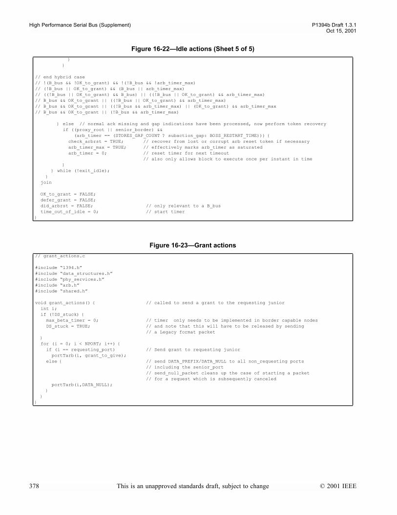
High Performance Serial Bus (Supplement) P1394b Draft 1.3.1Oct 15, 2001
// end hybrid case// !(B_bus && !OK_to_grant) && !(!B_bus && !arb_timer_max)// (!B_bus || OK_to_grant) && (B_bus || arb_timer_max)// ((!B_bus || OK_to_grant) && B_bus) || ((!B_bus || OK_to_grant) && arb_timer_max)// B_bus && OK_to_grant || ((!B_bus || OK_to_grant) && arb_timer_max)// B_bus && OK_to_grant || ((!B_bus && arb_timer_max) || (OK_to_grant) && arb_timer_max// B_bus && OK_to_grant || (!B_bus && arb_timer_max)
else // normal ack missing and gap indications have been processed, now perform token recovery if ((proxy_root || senior_border) && (arb_timer == (STORES_GAP_COUNT ? subaction_gap: BOSS_RESTART_TIME))) check_arbrst = TRUE; // recover from lost or corrupt arb reset token if necessary arb_timer_max = TRUE; // effectively marks arb_timer as saturated arb_timer = 0; // reset timer for next timeout // also only allows block to execute once per instant in time while (!exit_idle); join
OK_to_grant = FALSE; defer_grant = FALSE; did_arbrst = FALSE; // only relevant to a B_bus time_out_of_idle = 0; // start timer
Figure 16-23Grant actions
// grant_actions.c
#include 1394.h#include data_structures.h#include phy_services.h#include arb.h#include shared.h
void grant_actions() // called to send a grant to the requesting junior int i; if (!DS_stuck) max_beta_timer = 0; // timer only needs to be implemented in border capable nodes DS_stuck = TRUE; // and note that this will have to be released by sending // a Legacy format packet for (i = 0; i < NPORT; i++) if (i == requesting_port) // Send grant to requesting junior portTarb(i, grant_to_give); else // send DATA_PREFIX/DATA_NULL to all non_requesting ports // including the senior_port // send_null_packet cleans up the case of starting a packet // for a request which is subsequently canceled portTarb(i,DATA_NULL);
Figure 16-22Idle actions (Sheet 5 of 5)
378 This is an unapproved standards draft, subject to change © 2001 IEEE
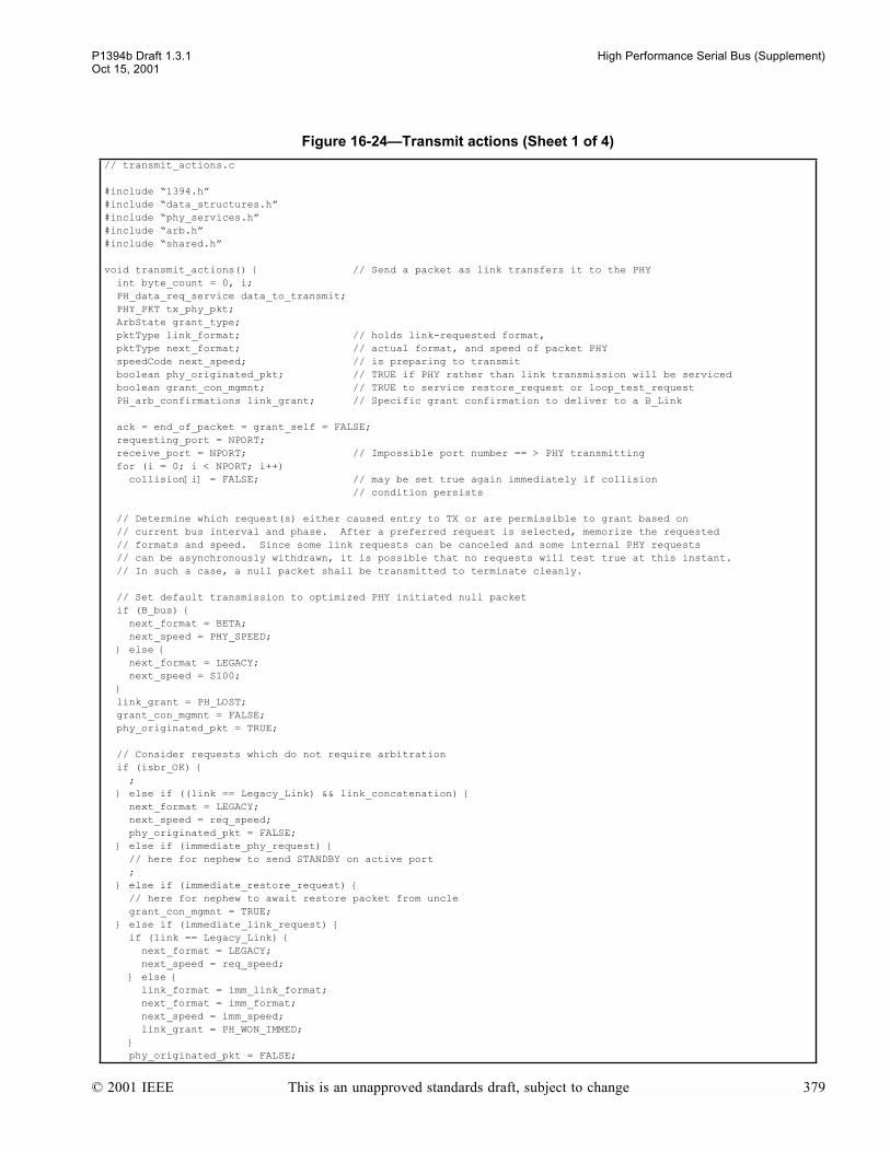
P1394b Draft 1.3.1 High Performance Serial Bus (Supplement)Oct 15, 2001
Figure 16-24Transmit actions (Sheet 1 of 4)
// transmit_actions.c
#include 1394.h#include data_structures.h#include phy_services.h#include arb.h#include shared.h
void transmit_actions() // Send a packet as link transfers it to the PHY int byte_count = 0, i; PH_data_req_service data_to_transmit; PHY_PKT tx_phy_pkt; ArbState grant_type; pktType link_format; // holds link-requested format, pktType next_format; // actual format, and speed of packet PHY speedCode next_speed; // is preparing to transmit boolean phy_originated_pkt; // TRUE if PHY rather than link transmission will be serviced boolean grant_con_mgmnt; // TRUE to service restore_request or loop_test_request PH_arb_confirmations link_grant; // Specific grant confirmation to deliver to a B_Link
ack = end_of_packet = grant_self = FALSE; requesting_port = NPORT; receive_port = NPORT; // Impossible port number == > PHY transmitting for (i = 0; i < NPORT; i++) collision[i] = FALSE; // may be set true again immediately if collision // condition persists
// Determine which request(s) either caused entry to TX or are permissible to grant based on // current bus interval and phase. After a preferred request is selected, memorize the requested // formats and speed. Since some link requests can be canceled and some internal PHY requests // can be asynchronously withdrawn, it is possible that no requests will test true at this instant. // In such a case, a null packet shall be transmitted to terminate cleanly.
// Set default transmission to optimized PHY initiated null packet if (B_bus) next_format = BETA; next_speed = PHY_SPEED; else next_format = LEGACY; next_speed = S100; link_grant = PH_LOST; grant_con_mgmnt = FALSE; phy_originated_pkt = TRUE;
// Consider requests which do not require arbitration if (isbr_OK) ; else if ((link == Legacy_Link) && link_concatenation) next_format = LEGACY; next_speed = req_speed; phy_originated_pkt = FALSE; else if (immediate_phy_request) // here for nephew to send STANDBY on active port ; else if (immediate_restore_request) // here for nephew to await restore packet from uncle grant_con_mgmnt = TRUE; else if (immediate_link_request) if (link == Legacy_Link) next_format = LEGACY; next_speed = req_speed; else link_format = imm_link_format; next_format = imm_format; next_speed = imm_speed; link_grant = PH_WON_IMMED; phy_originated_pkt = FALSE;
© 2001 IEEE This is an unapproved standards draft, subject to change 379
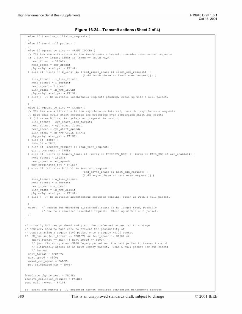
High Performance Serial Bus (Supplement) P1394b Draft 1.3.1Oct 15, 2001
else if (resolve_collision_request) ; else if (send_null_packet) ; else if (grant_to_give == GRANT_ISOCH) // PHY has won arbitration in the isochronous interval, consider isochronous requests if ((link == Legacy_Link) && (breq == ISOCH_REQ)) next_format = LEGACY; next_speed = req_speed; phy_originated_pkt = FALSE; else if ((link == B_Link) && ((odd_isoch_phase && isoch_odd_request) || (!odd_isoch_phase && isoch_even_request))) link_format = i_link_format; next_format = i_format; next_speed = i_speed; link_grant = PH_WON_ISOCH; phy_originated_pkt = FALSE; else // No suitable isochronous requests pending, clean up with a null packet. ; else if (grant_to_give == GRANT) // PHY has won arbitration in the asynchronous interval, consider asynchronous requests // Note that cycle start requests are preferred over arbitrated short bus resets if ((link == B_Link) && cycle_start_request && root) link_format = cyc_start_link_format; next_format = cyc_start_format; next_speed = cyc_start_speed; link_grant = PH_WON_CYCLE_START; phy_originated_pkt = FALSE; else if (isbr) isbr_OK = TRUE; else if (restore_request || loop_test_request) grant_con_mgmnt = TRUE; else if ((link == Legacy_Link) && ((breq == PRIORITY_REQ) || (breq == FAIR_REQ && arb_enable))) next_format = LEGACY; next_speed = req_speed; phy_originated_pkt = FALSE; else if ((link == B_Link) && (current_request || (odd_async_phase && next_odd_request) || (!odd_async_phase && next_even_request))) link_format = a_link_format; next_format = a_format; next_speed = a_speed; link_grant = PH_WON_ASYNC; phy_originated_pkt = FALSE; else // No suitable asynchronous requests pending, clean up with a null packet. ; else // Reason for entering TX:Transmit state is no longer true, possibly // due to a canceled immediate request. Clean up with a null packet. ;
// normally PHY can go ahead and grant the preferred request at this stage // however, need to take care to prevent the possibility of // concatenating a Legacy S100 packet onto a Legacy >S100 packet if (!B_bus && (cur_format == LEGACY) && (cur_speed != S100) && (next_format == BETA || next_speed == S100)) // just finishing a non-S100 Legacy packet and the next packet to transmit could // ultimately appear as an S100 Legacy packet. Send a null packet (or bus reset) // instead next_format = LEGACY; next_speed = S100; grant_con_mgmnt = FALSE; phy_originated_pkt = TRUE;
immediate_phy_request = FALSE; resolve_collision_request = FALSE; send_null_packet = FALSE;
if (grant_con_mgmnt) // selected packet requires connection management service
Figure 16-24Transmit actions (Sheet 2 of 4)
380 This is an unapproved standards draft, subject to change © 2001 IEEE
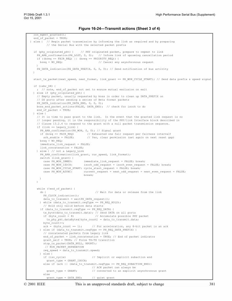
P1394b Draft 1.3.1 High Performance Serial Bus (Supplement)Oct 15, 2001
con_mgmnt_granted(); end_of_packet = TRUE; else // Begin packet transmission by informing the link as required and by preparing // the Serial Bus with the selected packet prefix
if (phy_originated_pkt) // PHY originated packet, prepare to repeat to link PH_ARB_confirmation(PH_LOST, 0, 0); // Inform link of upcoming cancellation period if ((breq == FAIR_REQ) || (breq == PRIORITY_REQ)) breq = NO_REQ; // Cancel any asynchronous request PH_DATA_indication(PH_DATA_PREFIX, 0, 0, 0); // Send notification of bus activity
start_tx_packet(next_speed, next_format, link_grant == PH_WON_CYCLE_START); // Send data prefix & speed signal
if (isbr_OK) ; // note, end_of_packet not set to ensure mutual exclusion on exit else if (phy_originated_pkt) // Empty packet, usually requested by boss in order to clean up DATA_PREFIX on // DS ports after sending a series of Beta format packets PH_DATA_indication(PH_DATA_END, 0, 0, 0); boss_end_packet_actions(FALSE, DATA_END); // check for isoch to do end_of_packet = TRUE; else // It is time to pass grant to the link. In the event that the granted link request is no // longer pending, it is the responsibility of the PHY/link Interface block described in // Clause 13.2.4 to respond to the grant with a null packet transmission sequence. if (link == Legacy_Link) PH_ARB_confirmation(PH_WON, 0, 0); // Signal grant if (breq == FAIR_REQ) // Exhausted one fair request per fairness interval? arb_enable = FALSE; // Yes, clear permission (set again on next reset gap) breq = NO_REQ; immediate_link_request = FALSE; link_concatenation = FALSE; else // not a Legacy_Link PH_ARB_confirmation(link_grant, cur_speed, link_format); switch (link_grant) case PH_WON_IMMED: immediate_link_request = FALSE; break; case PH_WON_ISOCH: isoch_odd_request = isoch_even_request = FALSE; break; case PH_WON_CYCLE_START: cycle_start_request = FALSE; break; case PH_WON_ASYNC: current_request = next_odd_request = next_even_request = FALSE; break; while (!end_of_packet) do // Wait for data or release from the link PH_CLOCK_indication(); data_to_transmit = waitPH_DATA_request(); while (data_to_transmit.reqType == PH_REQ_HOLD); // Hold only valid before data starts if (data_to_transmit.reqType == PH_REQ_DATA) tx_byte(data_to_transmit.data); // Send DATA on all ports if (byte_count < 8) // Accumulate possible PHY packet tx_phy_pkt.dataBytes[byte_count] = data_to_transmit.data; byte_count++; ack = (byte_count == 1); // For acceleration, any 8-bit packet is an ack else if (data_to_transmit.reqType == PH_REQ_DATA_PREFIX) // concatenated packets from Legacy link end_of_packet = link_concatenation = TRUE; // End of packet indicator grant_self = TRUE; // Force TX:TX transition stop_tx_packet(DATA_NULL, NPORT); // MIN_PACKET_SEPARATION req_speed = data_to_transmit.speed; else if (iso_cycle) // Implicit or explicit subaction end grant_type = GRANT_ISOCH; else if (ack || (data_to_transmit.reqType == PH_REQ_SUBACTION_END)) // ACK packet can always be grant_type = GRANT; // converted to an explicit asynchronous grant else grant_type = DATA_END; // quiet grant
Figure 16-24Transmit actions (Sheet 3 of 4)
© 2001 IEEE This is an unapproved standards draft, subject to change 381
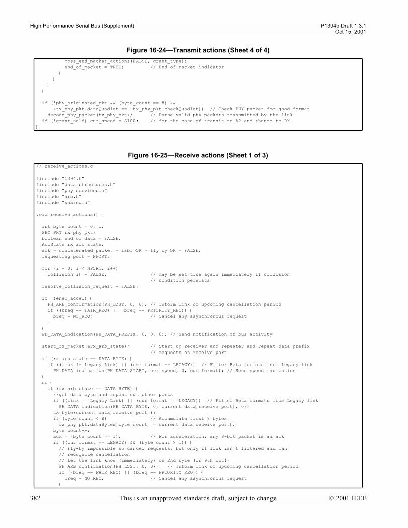
High Performance Serial Bus (Supplement) P1394b Draft 1.3.1Oct 15, 2001
boss_end_packet_actions(FALSE, grant_type); end_of_packet = TRUE; // End of packet indicator
if (!phy_originated_pkt && (byte_count == 8) && (tx_phy_pkt.dataQuadlet == ~tx_phy_pkt.checkQuadlet)) // Check PHY packet for good format decode_phy_packet(tx_phy_pkt); // Parse valid phy packets transmitted by the link if (!grant_self) cur_speed = S100; // for the case of transit to A2 and thence to RX
Figure 16-25Receive actions (Sheet 1 of 3)
// receive_actions.c
#include 1394.h#include data_structures.h#include phy_services.h#include arb.h#include shared.h
void receive_actions()
int byte_count = 0, i; PHY_PKT rx_phy_pkt; boolean end_of_data = FALSE; ArbState rx_arb_state; ack = concatenated_packet = isbr_OK = fly_by_OK = FALSE; requesting_port = NPORT;
for (i = 0; i < NPORT; i++) collision[i] = FALSE; // may be set true again immediately if collision // condition persists resolve_collision_request = FALSE;
if (!enab_accel) PH_ARB_confirmation(PH_LOST, 0, 0); // Inform link of upcoming cancellation period if ((breq == FAIR_REQ) || (breq == PRIORITY_REQ)) breq = NO_REQ; // Cancel any asynchronous request PH_DATA_indication(PH_DATA_PREFIX, 0, 0, 0); // Send notification of bus activity
start_rx_packet(&rx_arb_state); // Start up receiver and repeater and repeat data prefix // requests on receive_port if (rx_arb_state == DATA_BYTE) if ((link != Legacy_Link) || (cur_format == LEGACY)) // Filter Beta formats from Legacy link PH_DATA_indication(PH_DATA_START, cur_speed, 0, cur_format); // Send speed indication do if (rx_arb_state == DATA_BYTE) //get data byte and repeat out other ports if ((link != Legacy_Link) || (cur_format == LEGACY)) // Filter Beta formats from Legacy link PH_DATA_indication(PH_DATA_BYTE, 0, current_data[receive_port], 0); tx_byte(current_data[receive_port]); if (byte_count < 8) // Accumulate first 8 bytes rx_phy_pkt.dataBytes[byte_count] = current_data[receive_port]; byte_count++; ack = (byte_count == 1); // For acceleration, any 8-bit packet is an ack if ((cur_format == LEGACY) && (byte_count > 1)) // Fly-by impossible so cancel requests, but only if link isnt filtered and can // recognize cancellation // Let the link know (immediately) on 2nd byte (or 9th bit!) PH_ARB_confirmation(PH_LOST, 0, 0); // Inform link of upcoming cancellation period if ((breq == FAIR_REQ) || (breq == PRIORITY_REQ)) breq = NO_REQ; // Cancel any asynchronous request
Figure 16-24Transmit actions (Sheet 4 of 4)
382 This is an unapproved standards draft, subject to change © 2001 IEEE

P1394b Draft 1.3.1 High Performance Serial Bus (Supplement)Oct 15, 2001
if (fifo_rd_ptr[receive_port] == fifo_wr_ptr[receive_port]) // FIFO underrun // - just emptied the FIFO, and a new byte has not come in!! end_of_data = TRUE; rx_arb_state = IDLE; // assume packet_ending[receive_port] = TRUE; // inform process_requests() that packet has concluded next_arb[receive_port] = FALSE; // and let the FIFO advance eagerly advance_OK[receive_port] = TRUE; else rx_arb_state=portR_next_arb(receive_port); else end_of_data = TRUE; while (!end_of_data); if ((cur_format == LEGACY) && !ack) // Fly-by impossible so cancel requests, but only if link isnt filtered and can // recognize cancellation PH_ARB_confirmation(PH_LOST, 0, 0); // Inform link of upcoming cancellation period if ((breq == FAIR_REQ) || (breq == PRIORITY_REQ)) breq = NO_REQ; // Cancel any asynchronous request
// send packet ending, depends on the received packet ending switch (rx_arb_state) case DATA_PREFIX: case DATA_NULL: concatenated_packet = TRUE; if ((link != Legacy_Link) || (cur_format == LEGACY)) // Dont send redundant indication if PH_DATA_indication(PH_DATA_PREFIX, 0, 0, 0); // Legacy link is already in DATA_PREFIX stop_tx_packet(rx_arb_state, NPORT); break; case GRANT: case GRANT_ISOCH: case DATA_END: if ((link != Legacy_Link) || (cur_format == LEGACY)) // Filter Beta formats from Legacy link PH_DATA_indication(PH_DATA_END, 0, 0, 0); // Test for fly-by possibility for Legacy link requests, remembering not to attempt fly-by // if the link is currently being filtered from reception of a BETA format packet fly_by_OK = (cur_format == LEGACY) && fly_by_permitted(); if (fly_by_OK) grant_to_give = (breq == ISOCH_REQ ? GRANT_ISOCH : GRANT); stop_tx_packet(grant_to_give, NPORT); else if (ack && (receive_port != senior_port)) rx_arb_state = GRANT; // ACK packet from a junior port can always be // converted to an explicit asynchronous grant if ((rx_arb_state == GRANT) || (rx_arb_state == GRANT_ISOCH) || // explicit grants ((rx_arb_state == DATA_END) && (receive_port != senior_port))) // implicit grant boss_end_packet_actions(receive_port == senior_port, rx_arb_state); else // not BOSS, repeat end of packet normally stop_tx_packet(DATA_END, NPORT); break; case BUS_RESET: PH_DATA_indication(PH_DATA_END, 0, 0, 0); stop_tx_packet(BUS_RESET, NPORT); break; case IDLE: // DP directly to IDLE from a Legacy PHY case ARB_CONTEXT: if ((link != Legacy_Link) || (cur_format == LEGACY)) // Filter Beta formats from Legacy link PH_DATA_indication(PH_DATA_END, 0, 0, 0); // clean up for the link if (non_null_packet) // Unexpected end of data... stop_tx_packet(DATA_END, NPORT); // and try to clean up gracefully else if (format_committed) // Already in packet context? stop_tx_packet(ARB_CONTEXT, NPORT); // If so, set arb context before heading to IDLE else stop_tx_packet(IDLE, NPORT); ack = FALSE; // Disable fly-by acceleration break; default: // Unexpected end of data... if ((link != Legacy_Link) || (cur_format == LEGACY)) // Filter Beta formats from Legacy link PH_DATA_indication(PH_DATA_END, 0, 0, 0); // clean up for the link non_null_packet = FALSE; // With unexpected end of data, dont add dribble bits
Figure 16-25Receive actions (Sheet 2 of 3)
© 2001 IEEE This is an unapproved standards draft, subject to change 383

High Performance Serial Bus (Supplement) P1394b Draft 1.3.1Oct 15, 2001
stop_tx_packet(DATA_END, NPORT); // and try to clean up gracefully ack = FALSE; // Disable fly-by acceleration break;
good_phy_packet = FALSE; if (byte_count == 8) if (rx_phy_pkt.dataQuadlet == ~rx_phy_pkt.checkQuadlet) // Check PHY packet for good format decode_phy_packet(rx_phy_pkt); // Parse valid phy packets good_phy_packet = TRUE; else HR_mode = LTP_TEST; // for all non-PHY packets if (!concatenated_packet) cur_speed = S100; // remember current speed for // concatenated (Legacy) packets
Figure 16-25Receive actions (Sheet 3 of 3)
384 This is an unapproved standards draft, subject to change © 2001 IEEE
P1394b Draft 1.3.1 High Performance Serial Bus (Supplement)Oct 15, 2001
Annex A. Annex K IEEE standard 1394-1995 supplement -- bulk cable specification
Test methodology for 1394 bulk serial bus cable.
A.1 Reference K.3 Signal pair characteristic impedance
A.1.1 Equipment
a) Tektronix 11802 differential TDR with SD24 sampling Head or equivalent. b) Adapters Tektronix SIU 800 Static Isolation Unit or equivalent, c) Two 300 mm lengths of 50 Ω RG405 cable terminated with a four socket computer interface.
A.1.2 Sample.
4.5 m length of cable with one end stripped back 12 mm
A.1.3 Method.
The calibration is checked to 50 Ω ± 1 Ω. The TDR delta delay is adjusted to electrically match the end of the adapter.
The differential mode characteristic impedance is checked by connecting one pair to M1 and M2 with shield foil con-nected to ground. The entire cable length is displayed on the main trace, M1-M2, which displays any impedance variationin the pair. The window displays approximately the first 1.5 ns of the pair closest to the launching connector and after theconnector mismatch. An average is taken using measurement mean and represented with a horizontal cursor set in Ro.This test is repeated for both signal pairs.
The signal pair characteristic impedance (common mode) is measured as above but with one pair connected to M1 andground and the other pair connected to M2 and ground. The shields should be left floating. The entire cable length is dis-played on main trace M1 & M2. The window displays first M1 then M2 with the measurement taken same as above.
A.1.4 Results
To comply with this specification the results of the above tests should be in accordance with section 5.4.2
A.2 Reference K.4 Signal pair attenuation.
A.2.1 Equipment
a) Wiltron 610 Network analyzer or equivalent. b) Adapters - two 180 Degree differential pulse splitters. c) Four matching pads and four 150 mm lengths of 50 Ω RG405 cable terminated with a quick release dip socket.
A.2.2 Sample
4.5 m length of cable with both ends stripped back 12 mm.
A.2.3 Method
The calibration is done from 40 MHz to 3200 MHz to the end of the matching pads. The through line is zeroed to thesocket.
© 2001 IEEE This is an unapproved standards draft, subject to change 385

P1394b Draft 1.3.1 High Performance Serial Bus (Supplement)Oct 15, 2001
The differential mode attenuation is checked by connecting one end of a pair to port 1 and the other end to port 2 with theshield foil connected to the minus terminal. The pair is displayed using S21 in log magnitude at 5% smoothing, withmarkers set at 100 MHz, 200 MHz, 400 MHz, 800 MHz, 1600 MHz, 3200 MHz. This test is repeated for both signalpairs.
A.2.4 Results
To comply with this specification the results of the above tests should be in accordance with section 5.4.3
A.3 Reference K.5 Signal pair velocity of propagation (TDR)
A.3.1 Equipment
a) Tektronix 11802 differential TDR with SD24 sampling head or equivalent. b) Adapters - Tektronix SIU 800 Static Isolation Unit or equivalent. c) Two 300 mm lengths of 50 Ω RG405 cable terminated with a four socket computer interface.
A.3.2 Sample
4.5m length of cable with one end stripped back 12 mm.
A.3.3 Method
The calibration is checked to 50 Ω ± 1 Ω. The TDR delta delay is adjusted to electrically match the end of the adapter.
The differential mode propagation delay is checked by connecting one pair to M1 and M2 with shield foil connected toground. The entire cable length is displayed on the main trace M1-M2. The window is first set to display the launchingconnector and a cursor is set at the last rise of the connector mismatch and zeroed. The window is then moved to the endof the pair and the cursor is set directly before the first rise. This test is repeated for both signal pairs.
A.3.4 Results
To comply with this specification the results of the above tests should be in accordance with sections 5.4.4 and 5.4.6
A.4 Reference K.5 Signal pair velocity of propagation (Freq. sweep)
A.4.1 Equipment
a) Wiltron 610 Network analyzer or equivalent. b) Adapters - two 180 Degree differential pulse splitters. c) Four matching pads and four 150 mm lengths of 50 Ω RG405 cable terminated with a quick release dip socket.
A.4.2 Sample
4.5 m length of cable with both ends stripped back 12 mm.
A.4.3 Method
The calibration is done from 40 MHz to 3200 MHz to the end of the matching pads. The through line is zeroed to thesocket.
© 2001 IEEE This is an unapproved standards draft, subject to change 386
P1394b Draft 1.3.1 High Performance Serial Bus (Supplement)Oct 15, 2001
The differential mode propagation delay is checked by connecting one end of a pair to port 1 and the other end to port 2with the shield foil connected to the minus terminal. The pair is displayed using S21 in time bandpass mode with a markerset at the end of the pair directly before the first rise. This test is repeated for both signal pairs at 100 MHz, 200 MHz,400 MHz, 800 MHz, 1600 MHz, 3200 MHz.
A.4.4 Results
To comply with this specification the results of the above tests should be in accordance with section 5.4.4
A.5 Rise and fall time
A.5.1 Equipment
a) Tektronix 11801 differential TDR with SD24 sampling Head or equivalent. b) Hewlett Packard HP 8133A Pulse generator or equivalent. c) Adapters - two 150 Ω lengths of 50 Ω RG402 cable terminated with DB9F connectors.
A.5.2 Sample
4.5 m length of cable with both ends stripped back 12 mm.
A.5.3 Method
The calibration is checked to 50 Ω ± 1 Ω. The TDR delta delay is adjusted to electrically match the end of the adapter.The pulse generator is set at 600 mV amplitude, 0.0 volts offset, 500 MHz frequency, 31 ns pulse width, Square mode.The trigger output of the pulse generator is connected to the TDR.
The rise and fall times are measured by connecting one end of the pair to output 2 of the pulse generator and the otherend of pair to M1 & M2 with shield foil grounded. The first square wave is displayed in color graduated mode on themain trace, M1-M2. The vertical size should be set to fill all ten graticules, i.e 100%. The vertical cursors should be set
© 2001 IEEE This is an unapproved standards draft, subject to change 387

High Performance Serial Bus (Supplement) P1394b Draft 1.3.1Oct 15, 2001
to 20% and 80% so that the rise and fall times can be easily measured as the time interval between the trace movingbetween the 20% and 80% points and vice-versa. The test is repeated for both pairs at 1000 MHz, 2000 MHz and 3000MHz..
A.5.4 Results
To comply with this specification the results of the above tests should be in accordance with section 5.4.5
A.6 Static Shield Isolation (insulation resistance)
A.6.1 Equipment
a) Quad Tech 1865 Insulation Resistance Tester or equivalent. b) Adapters - two connecting wires, insulated to 500 V and terminated with standard Banana clips.
A.6.2 Sample
4.5m length of cable with one end stripped back 12 mm.
A.6.3 Method
This test should be made on a well insulted work bench. The meter is calibrated to zero.
NOTE1.0 GHz skew shield grounded
Figure A-1 Reference to rise and fall time
388 This is an unapproved standards draft, subject to change © 2001 IEEE
P1394b Draft 1.3.1 High Performance Serial Bus (Supplement)Oct 15, 2001
The insulation resistance is checked by three measurements wire to wire and individual wire to shield. The measurementis taken at 500 V for 1 minute. This test is repeated for both signal pairs.
A.6.4 Results
To comply with this specification the results of the above tests should be in accordance with section 5.4.
© 2001 IEEE This is an unapproved standards draft, subject to change 389

High Performance Serial Bus (Supplement) P1394b Draft 1.3.1Oct 15, 2001
390 This is an unapproved standards draft, subject to change © 2001 IEEE

P1394b Draft 1.3.1 High Performance Serial Bus (Supplement)Oct 15, 2001
Annex B. Jitter measurements (normative)
The following clauses provide specific transmitter test patterns to facilitate jitter measurements.
Jitter measurements shall be made using an appropriate test method as described in NCITS TR-25-1999 1-SEP-1999Information Technology - Fibre Channel - Methodologies for Jitter Specificaton, referred to as the MJS report. In partic-ular it is recommended that Time Interval Analysis be used to measure jitter output.
B.1 Test patterns
The test patterns recommended in the Fibre Channel MJS report are specific to Fibre Channel encoding and frame format.Similar patterns are specified here. It should be noted that although the MJS report provides different patterns for usewhen measuring jitter output and jitter tolerance, and a third pattern specific to measuring supply noise, experience hasshown that all three patterns test may reveal failure modes when used for both measuring jitter output and jitter tolerance.Therefore all three patterns described below shall be used for both jitter output and jitter tolerance tests.
The jitter test patterns have been devised so that they may be generated by test software, but run on a normal 1394 nodewith no special hardware modification or test modes (apart from the required ability to disable the transmit scramblerduring packet payload transmission).
A test configuration shall comprise the device under test and a second device to provide a working bus. Each port on thedevice under test is tested independently. The port used on the second device shall be capable of operating at the maxi-mum operating speed of the port under test on the device under test. In the case of jitter tolerance tests, the second devicewill generate the test pattern as described below. Note that the connection between the two devices will contain extra cir-cuitry and/or test equipment appropriate to the test method being used.
The packet format used is a compliant asynchronous packets (with normal header and checksum). The packets shall beaddressed to node 2 (thus, even when not scrambled, will be ignored by the receiving nodes link layer).
B.2 Random pattern (SB_RPAT)
Unlike Fibre Channel, this standard has an excellent in-built random pattern generator in the form of the scrambler. Thusthe random pattern shall bean indefinitely repeated sequence of maximum size asynchronous packets (depending on trans-mission speed, see 16.1), which shall be transmitted continuously (e.g. by using CURRENT_ASYNC requests, ignoringfairness). The packet payload should be all zeros, which will be scrambled by the transmitting PHY into a random pattern.A TIA should be primed to capture each packet.
B.3 Receive jitter tolerance pattern (SB_JTPAT)
This pattern comprises sequence of symbols providing a low density pattern followed by a sequence of symbols providinga high density pattern.Using these two patterns together tests the tolerance to phase jumps caused by systematic patternjitter. The run length of these two patterns are related to the time constants of the PLL. For the Fibre Channel JTPAT thefollowing assumptions were made:
1) Average FC traffic transition density is approximately 50%.2) CDR time constant is inversely proportional to transition density.3) To obtain at least 95% settling a pattern duration needs to be greater than 3 time constants4) The PLLs minimum bandwidth for FC transceivers is 637kHz.
100 10 bit characters at 50% transition density meets these assumptions. For Fibre Channel, the repeating D21.5 is usedas it has a 100% transition density and the repeating D30.3 is used as it has a 30% transition density. Because of theabove assumptions, the duration of the high transition density pattern needs to be at least 50 10 bit characters. As for thelow transition density pattern, it needs to be at least 167 10 bit characters.
© 2001 IEEE This is an unapproved standards draft, subject to change 391

High Performance Serial Bus (Supplement) P1394b Draft 1.3.1Oct 15, 2001
In the case of this standard, the control symbols provide approximately a 30% transition density when scrambled. How-ever, the scrambled data characters will provide only 50%. If the transmit scrambler is disabled, then 100% transition den-sity can be achieved by using D21.5 symbols.
For this test, the transmitter data scrambler shall be disabled once synchronization has been achieved and the port_errorregister of the receive port shall be read in order to clear it. Error rate shall be computed from the values obtained by reg-ularly reading the port_error register.
The test pattern shall comprise a sequence of at least 42 null packets followed by a packet containing at least 50 bytes ofconsecutive D21.5 symbols (8 bit data value AD16). This pattern (42 null packets followed by a packet with D21.5 data)is repeated indefinitely. Best results when measuring output jitter will normally be found if the TIA is armed to start at thebeginning of a packet (for this purpose, it is sufficient to arm the TIA to start on a sequence of 5 zeros or 5 ones, whichwill capture between 80% and 90% of all packets), and the transitions are captured for the duration of one period of therepeating cycle. The sequence of 42 null packets may be generated by repeatedly issuing CURRENT_ASYNC requestsand providing a zero length PHY packet - thus generating a repeating sequence of DATA_PREFIX DATA_PREFIXDATA_END DATA_END. As it is not required that link devices support the transmission of zero length null packets, anacceptable alternative is to transmit single quadlet or two quadlet PHY packets containing the repeated data byte D30.3 (8bit data value 0x7E). The total length of this part of the test pattern, comprising the repeated PHY packets, shall be atleast 167 symbols.
Note that the length of the two parts of the test pattern may need adjustment (following the guidelines given above andthe test guidelines given in the MJS report) according to the cut-off frequency of the receiver PLL, particularly for trans-mission at speeds other than S800.
B.4 Supply noise test sequence (SB_SPAT)
The aim of this test sequence is to maximize supply noise by changing all lines on a parallel PHY/Link interface. It shallcomprise a maximum length asynchronous packet containing alternate 0016 and FF16 bytes, which shall be transmittedrepeatedly. The scrambler shall be enabled for this test sequence. If there is no parallel PHY/Link interface, or a serialPHY/Link interface is used, then a system dependent method of maximizing supply noise should be used, for example bytransmitting data across an electrically proximate system bus which alternates between all ones and all zeros on succes-sive clocks.
392 This is an unapproved standards draft, subject to change © 2001 IEEE

P1394b Draft 1.3.1 High Performance Serial Bus (Supplement)Oct 15, 2001
Annex C. Connection status change (informative)
The design of the algorithm which is used during disconnection and during suspend in order to detect a change in portstatus is based on the following fundamental properties of TpBias, toning and the Connect Detect circuitry, given with thereasoning on each.
#1. Can't tone and drive TpBias simultaneously.
Legacy PHY's would attempt to interpret the tone if TpBias were present. The only safe way to tone into a Legacy port iswhen TpBias is deasserted.
#2. Can't wait for remote port on peer PHY to initiate TpBias.
A Legacy node w/ a suspended port won't initiate TpBias as long as the DC connection status is continually active. Con-sider a Legacy PHY and a B PHY which are connected via a suspended link. Subsequently, if the B PHY experiences apower-on reset (device powered off for a while and then turned back on), it needs to re-establish connectivity with theLegacy node. If the eager Beta algorithm waited for the Legacy device to initiate TpBias... it would never come. Conse-quently, at least one step in eager Beta has to lead to the initiation of a TpBias handshake.
#3. Can't assume initial receipt of TpBias means a Legacy device is attached.
If a Beta port (called X) tries toning first and hears nothing, then according to #2 above, it will have to initiate TpBias. Ifa connected Beta port (called Y) on a peer PHY then powers up, it will detect TpBias without a tone. Thus, assuming thepresence of TpBias always indicates a Legacy port leads to a false detection of the remote peer. To avoid this, port Yshould tone first even if it sees TpBias. Port X, which is still driving TpBias, has to turn TpBias off first (see #5) and thenstill listen for a tone. After detecting the tone from Port Y, Port X will revert to toning and the Beta mode handshake cancommence.
#4. During upstarting, need to initiate toning with some frequency.
Assume an AC path between two Beta ports and allow that the ac path can have passive connection points (RJ-45 jack onthe wall or in the patch panel, a optical wall socket, etc.). If the passive connection is not in place, the two B nodes atpower-on reset will attempt to initiate a handshake. Both progress to the TpBias assertion phase mandated in #2 abovewithout ever detecting the remote port. If the eager Beta scheme stopped at this point with the continuous assertion ofTpBias, a later connection at the passive point won't be detected by either node. For this reason, the eager Beta procedureattempts toning with some frequency to allow for passive connections. (A local_plug_present feature at the PHYdoesn't handle the case of passive connection points in-between the attached ports.) This suggests that the eager Betasequence would need to generate TpBias. After a single phase of TpBias the procedure then reverts to continuously ton-ing.
#5. Can't listen for a tone when generating TpBias.
When generating TpBias, the remote node may be a 1394-1995 node (or indeed a 1394a-2000 node). Such a node willinterpret the TpBias signal as a connection, and will start sending arbitration signals (such as reset). These will trip thesignal-detect mechanism, which operates by looking for a differential signal on TPA.
Corollary to property #5: A Beta-PHY doesn't need to send a tone when receiving TpBias because the Beta-PHY on theother end of the cable that's generating TpBias can't listen for the tone anyway.
#6. Cant listen for TpBias whilst generating a tone.
When generating a tone, the local PHY will be providing an internally generated bias level on TPB around which to sendthe signal. This will, in general, be detected by the local TpBias detector. There is no filter on the TpBias detector onsensing loss of TpBias, and it is assumed that the bias bit will report zero as soon as the transmission of the tone ceases.
© 2001 IEEE This is an unapproved standards draft, subject to change 393

High Performance Serial Bus (Supplement) P1394b Draft 1.3.1Oct 15, 2001
NOTEIn general, generating a tone whilst the peer is generating Bias may cause level shifts in the peers TpBias, and, in the case ofPHYs with a single TpBias generator, may corrupt traffic being repeated through that PHY. It is therefore important that a B PHYshould avoid generating a tone when incoming Bias is present (see corollary to property #5). In practice, this is unavoidable as acorollary to property #6. However, if a B PHY checks for Bias immediately before generating a tone, then the problem is limited to therising edge of Bias, which can only occur when the peer PHY is powering up, and hence there will be no traffic corruption. It is alsoimportant to ensure that the Bias comparator is stable before generating tones.
#7. DC low current connect detect mechanism may give false negative.
An incoming tone on a DC coupled connection will be centered around a common mode bias which may raise the voltagehigher than the connect detect threshold (low voltage implies connection).
Corollary #1 to property #7: Cant use the DC comparator at all as soon as a tone is heared. This is because the tone inter-val is 41 ms but CONNECT_TIMEOUT is 330ms.
Corollary #2 to property #7: Don't try to maintain DC connected status in Beta mode.
NOTEThe behavior of the DC connect detect comparator, as defined in 1394a-2000, has an RC constant for discharging the capacitorfor the connected state of the order of 1.5 milliseconds. Once in this state, the RC constant for charging the capacitor (depending onthe circuit in the local PHY) to transition into the disconnected state is of the order of 100 milliseconds. Thus short disconnectsdue, say, to connection bounce or scrape won't be reported to the connection_status() logic, which therefore does not restart the timerfor such short disconnects. In effect, CONNECT_TIMEOUT is simply a time to allow the connector bouncing to settle down. Theconnection debounce algorithm is therefore simply to tone during a CONNECT_TIMEOUT interval and not to check that every tone isreceived.
#8. Cant support autocrossover on a DC connection.
Sending a tone on TPA (which will occur at some random interval if PMD_AUTOCROSSOVER_SUPPORTED reportsTRUE) results in the DC connect detector reporting a possibly false negative.
394 This is an unapproved standards draft, subject to change © 2001 IEEE

P1394b Draft 1.3.1 High Performance Serial Bus (Supplement)Oct 15, 2001
Index of C-code functions
NOTEall C-code function names listed here are hypertext links in electronic versions of this specification
Symbolsboolean *i_advance_interval, boolean *a_advance_interval) ..................................................... 353ArbState *received_grant) ........................................................................................................... 354
Avoid activate_connect_detect(int delay) ....................................................................................... 313boolean arb_permitted() ............................................................................................................... 352void arb_power_reset() ................................................................................................................ 366int arb_req_symbol_map(BetaRequestCode txrequest) ............................................................... 339boolean attach_pending() ............................................................................................................. 310
Bvoid bias_status() ......................................................................................................................... 307void boss_end_packet_actions(boolean grant_received_from_senior, ArbState grant_type) ..... 356void bport_receive_actions() ........................................................................................................ 336void bport_transmit_actions() ...................................................................................................... 340boolean bspeed_filter() ................................................................................................................ 334
Cvoid cancel_requests() .................................................................................................................. 359void capture_link_requests() ........................................................................................................ 359boolean character_sync() ............................................................................................................. 334void child_handshake_actions() ................................................................................................... 369boolean child_handshake_complete() .......................................................................................... 369void con_mgmnt_granted() .......................................................................................................... 309int config_req_symbol_map(ArbState txrequest) ........................................................................ 339void connection_status() .............................................................................................................. 317int control_symbol_map(ArbState txctrl, disparityType rd) ........................................................ 338
Dboolean data_coming() ................................................................................................................. 352boolean data_coming_on(int port) ............................................................................................... 352void dc_connection_detector() ..................................................................................................... 313void decode_bit() ......................................................................................................................... 325void decode_phy_packet(PHY_PKT phy_pkt) ........................................................................... 350void disabled_actions() ................................................................................................................ 320void ds_tx_bit(dataBit bit_to_send) ............................................................................................. 327void ds_tx_byte(byte data_byte) .................................................................................................. 327void dsport_transmit_actions() .................................................................................................... 328
ETX_arbstate encode(ArbState arb_state) ..................................................................................... 327
Fboolean fly_by_permitted() .......................................................................................................... 351
Gvoid gap_repeat_actions(int token_receive_port) ........................................................................ 358boolean gap_token(int port) ......................................................................................................... 365void grant_actions() ..................................................................................................................... 378
© 2001 IEEE This is an unapproved standards draft, subject to change 395

High Performance Serial Bus (Supplement) P1394b Draft 1.3.1Oct 15, 2001
Ivoid idle_actions() ........................................................................................................................374
Lboolean LEGACY_GRANT() ......................................................................................................353boolean Legacy_junior_requesting() ............................................................................................351void Legacy_request_actions() .....................................................................................................352int Legacy_symbol_count(speedCode spd) ..................................................................................346float Legacy_time(int n) ...............................................................................................................346void loop_detector() ......................................................................................................................310void loop_disabled_actions() ........................................................................................................324void loop_test_interval_actions() ..................................................................................................310
Nint new_test_value() ......................................................................................................................310void node_status_monitor() ..........................................................................................................306
Pvoid phy_response_actions() ........................................................................................................351boolean port_error_monitor() .......................................................................................................331void port_event_monitor() ............................................................................................................314void port_power_reset() ................................................................................................................313ArbState portR_next_arb(int port_num) .......................................................................................345void portTarb(int port_num, ArbState arb) ...................................................................................342void portTarb_at_speed(int port_num, ArbState arb, speedCode speed) .....................................342void portTspeed(int port_num, speedCode pkt_speed, pktType packet_format) .........................342void portTspeed_raw(int port_num, speedCode speed) ...............................................................342void process_requests() .................................................................................................................361void push(portSymbol symbol_to_push) ......................................................................................331void push_data_zero() ...................................................................................................................331
Rvoid receive_actions() ...................................................................................................................382void receive_ok_monitor() ............................................................................................................315void receive_speed_indication() ...................................................................................................315void remote_access(int page, int port_num, int reg, int ext_type) ................................................349void remote_command(int cmnd, int e_cmnd, int port_num) ......................................................349void request_type_map(int request) ..............................................................................................331boolean reset_complete() ..............................................................................................................368boolean reset_detected() ...............................................................................................................366void reset_start_actions() ..............................................................................................................366void reset_wait_actions() ..............................................................................................................367void restore_actions() ....................................................................................................................321boolean restore_in_progress() .......................................................................................................307void restore_port() ........................................................................................................................307void resume_actions() ...................................................................................................................320void resume_all_ports() ................................................................................................................307boolean resume_in_progress() ......................................................................................................306boolean resume_rx_OK() ..............................................................................................................307void root_contend_actions() .........................................................................................................369boolean rx_character() ..................................................................................................................333
396 This is an unapproved standards draft, subject to change © 2001 IEEE

P1394b Draft 1.3.1 High Performance Serial Bus (Supplement)Oct 15, 2001
int rx_comma_decode(int character_in, disparityType rd) .......................................................... 332int rx_control_decode(int character_in) ....................................................................................... 332void rx_control_map(int rx_ctrl) ................................................................................................. 331int rx_data_decode(int character_in, disparityType rd) ............................................................... 332void rx_off_actions() .................................................................................................................... 335PHY_PKT rx_PHY_packet(int port_num) .................................................................................. 308int rx_reqtype_decode(int character_in, disparityType rd) .......................................................... 332void rx_sync_actions() ................................................................................................................. 336void rx_sync_lost_actions() ......................................................................................................... 335
Svoid scrambler_sync_actions() .................................................................................................... 335void self_ID_grant_actions() ....................................................................................................... 370void self_ID_receive_actions() .................................................................................................... 371void self_ID_start_actions() ......................................................................................................... 370void self_ID_transmit_actions() .................................................................................................. 372void send_control(ArbState control, int not_to_port) .................................................................. 342void send_LTP() .......................................................................................................................... 307void send_tone() ........................................................................................................................... 314boolean set_Beta() ........................................................................................................................ 317void set_DS() ............................................................................................................................... 317void signal_detect_monitor() ....................................................................................................... 314boolean signal_detect_OK() ........................................................................................................ 315void speed_filter() ........................................................................................................................ 329void standby_actions() ................................................................................................................. 322void standby_initiator_actions() .................................................................................................. 322void standby_target_actions() ...................................................................................................... 322boolean start_port() ...................................................................................................................... 316boolean start_resume_port() ........................................................................................................ 316void start_rx_packet(ArbState *ending_arb) ............................................................................... 346void start_tx_packet(speedCode pkt_speed, pktType pkt, boolean send_cycle_start) ................ 343void stop_tx_packet(ArbState ending_status, int port_to_grant) ................................................ 344void stopped_clock_detector() ..................................................................................................... 326void suspend_all_active_ports() .................................................................................................. 306boolean suspend_in_progress() .................................................................................................... 306void suspend_initiator_actions() .................................................................................................. 321void suspend_target_actions() ...................................................................................................... 321void suspended_actions() ............................................................................................................. 321float symbol_time(speedCode symbol_speed) ............................................................................ 346
Tvoid toner() ................................................................................................................................... 315void train_character_sync() .......................................................................................................... 334void transmit_actions() ................................................................................................................ 379void tree_ID_start_actions() ........................................................................................................ 369void tx_byte(byte data_byte) ....................................................................................................... 342void tx_character(portSymbol tx) ................................................................................................ 339void tx_control(ArbState control, int r_port) ............................................................................... 346void tx_dribble_bits(TX_arbstate ending_status, boolean in_packet) ......................................... 327
© 2001 IEEE This is an unapproved standards draft, subject to change 397
High Performance Serial Bus (Supplement) P1394b Draft 1.3.1Oct 15, 2001
void tx_off_actions() .....................................................................................................................340void tx_PHY_packet(PHY_PKT packet_to_send, int port_num) ................................................308void tx_quadlet(quadlet quad_data) ..............................................................................................342void tx_speed_signal(speedCode tx_speed, pktType pkt_type) ...................................................340void tx_sync_actions() ..................................................................................................................340void tx_sync_lost_actions() ..........................................................................................................340
Uvoid untested_actions() .................................................................................................................322void update_descrambler() ............................................................................................................333disparityType update_rd(int character, disparityType rd) ............................................................330void update_scrambler() ...............................................................................................................339
Wvoid wait_Legacy_time(int n) .......................................................................................................346void wait_symbol_time(speedCode symbol_speed) .....................................................................346
398 This is an unapproved standards draft, subject to change © 2001 IEEE