
p 7518 Bicycle Power Generator Design for DC House
52
1 Bicycle Power Generator Design for DC House: Off Grid Energy Solutions Presented by: Brandon Hayes Louis Goguely Electrical Engineering Department California Polytechnic State University San Luis Obispo 2011
-
Upload
divya-tejaswini -
Category
Documents
-
view
12 -
download
0
description
power generation
Transcript of p 7518 Bicycle Power Generator Design for DC House

1
Bicycle Power Generator Design for DC House:
Off Grid Energy Solutions
Presented by:
Brandon Hayes
Louis Goguely
Electrical Engineering Department
California Polytechnic State University
San Luis Obispo
2011

2
Table of Contents: Table of contents ...........................................................................................................................................2
List of Tables/Figures ....................................................................................................................................3
Acknowledgements .......................................................................................................................................4
Abstract .........................................................................................................................................................5
1. Introduction ...........................................................................................................................................6
2. Background ...........................................................................................................................................9
3. Requirements .......................................................................................................................................11
4. Project Methods ...................................................................................................................................14
5. Design ..................................................................................................................................................16
Bike .........................................................................................................................................................16
Design of Stand .......................................................................................................................................18
Motor .......................................................................................................................................................26
Alternator.................................................................................................................................................28
DC Permenant Magnet ............................................................................................................................32
Mounting & Wiring .................................................................................................................................35
6. Integration and Cost ............................................................................................................................40
7. Tests and Planning ...............................................................................................................................43
8. Conclusion ...........................................................................................................................................48
Bibliography ................................................................................................................................................50
Appendices ..................................................................................................................................................51

3
List of Tables & Figures:
Tables
Table 5.1: Bill of Materials for Bike Stand.…………………………………….………………………….19
Table 6.1: Estimated and Actual Costs of Project.……………………........................................................41
Table 7.1: Output Current based on RPM for Ford 3G Alternator……………..…………………………..45
Figures
Figure 1.1: Energy Consumption Projections………………………………..……………………………...7
Figure 1.2: Energy Consumption Projections by Non-OECD economies…..………………………………7
Figure 3.1: Block Diagram of Overall Project Design…………..………………………………………….11
Figure 5.1: 3 pieces of 2‖x4‖x8’, 1 piece of 2‖x3‖x8’………….…………………………………....…….20
Figure 5.2: Mid-Peg to Mid-Peg Distance Defined………….……………………………………………..21
Figure 5.3: Visual of the Bike Stand Base……………….…………………………………………………21
Figure 5.4: Vertical Beam Placement on the Bike Stand Base….………………………..………………..22
Figure 5.5: Completed Back Half of the Bike Stand……………………………………………………….23
Figure 5.6: Front Tire Holder……………………………………………………….………………………24
Figure 5.7: Final Bike Stand Design with Bike and Alternator in Place……………….…………………..24
Figure 5.8: Output Current vs RPM for Ford 3G alternators...……………………….……………………29
Figure 5.9: Display of the Field Producing Parts, Stator, and Rotor…………………….…………………30
Figure 5.10: Diagram of rotor assembly in alternators…………………………………………………….30
Figure 5.11: Output Voltage vs. RPM of DC Motor....…………………………………………………….33
Figure 5.12a: Wiring of an Alternator...……………………………………………………………………34
Figure 5.12b: Wiring of an Alternator……………………………………………………………………..34
Figure 5.13: Mounting Alternator to Stand Figure…………………………………………………….…..36
Figure 5.14: Pulley Connection Between Alternator and Rim...…………………………………………..36
Figure 5.15: Battery Charging System Wiring…………………………………………………………….37
Figure 7.1: Alternator Bench Setup.……………………………………………………………………….43
Figure 7.2: Voltage Output based on RPM of Ford 3G alternator…………………………………………45
Figure 7.3: Current Output vs RPM………………………………………………………………………..46
Figure 7.4: Output Power vs RPM...……………………………………………………………………….46
Figure 7.5: Efficiency of alternator vs RPM……………………………………………………………….47

4
Acknowledgments:
Special thanks to the following individuals or organizations for their contributions and
support:
-Professor Taufik
-Achievement House
-Howard Siewert
-Virgil from the BRAE shop

5
Abstract: Our goal for this project is to design and implement a bicycle power generator for
the DC House Project. The DC House Project is an initiative to bring safe and reliable
power to the billions of people around the world without electricity. This goal will be
accomplished by designing a safe and sturdy human powered stationary bicycle that
produces DC energy. The DC power generated can be stored via batteries and used by the
local population to use for lights and other utilities that many take for granted on a daily
basis. Bicycle Power Generators are not a new idea, with many created by hobbyist for
residential use with small scale energy in mind, to charge batteries in case of a power
outage or natural disaster. We are looking to expand upon these designs and build a DC
generator that will convert human power into electrical power. The objective is to build a
device that is safer and more power efficient. If our product design were to be built and
shipped to people across the globe, it would be imperative that it meets all the safety
specifications that any national commercial product entails.
6
I. Introduction:
In today’s modern society, most people just flip a switch or push a button, and
everything we depend on is readily available. Cell phones, computers, televisions, heated
water, lights, and so much more, are all the backbone of any modern society’s
functionality. The electricity powering all these systems is something most people rarely
think about until the power is no longer available for use. The extensive system that
allows for an instant and near constant supply of conditioned power is referred to as the
―grid‖. This grid is usually supported by government and/or private in developed
countries; a government must have enough financial resources to establish and support a
significant investment to provide the service of electricity. With this idea in mind, it may
be hard to believe that nearly 80% of all people living in third world countries have no
access to electricity. That is an estimated 1.5 Billion people with no electricity[7].
This power crisis will not be getting better in the future. The U.S. Energy
Information Administration stated in their International Energy Outlook Report for 2010
that the world energy consumption will increase by 49 percent, or 1.4 percent per year,
from 495 quadrillion Btu in 2007 to 739 quadrillion Btu by 2035, as shown in Figure 1.1.
The Organization for Economic Co-operation and Development, OECD for short, is an
international organization, which includes a majority of the world’s most advanced
countries. Historically, OECD member countries have accounted for the largest share of
current world energy consumption; however, in 2007—for the first time—energy use
among non-OECD nations exceeded that among OECD nations as depicted in Figure 1.2.
If any growth in the world’s energy supply and infrastructure is to occur in the future, it is
likely the majority of this energy will go to these developed countries before any

7
developing or third world country. This will only exasperate the needs and deficiency of
these developing and third world countries.
Figure 1.1: Energy Consumption Projections[1] Figure 1.2: Energy Consumption Projections by
Non-OECD economies[1]
As of today, oil is by far the most used energy product in the world’s energy
supply, with coal at a distant second. According to the International Energy Agency, oil
products make up over 33% of the world’s energy supply, while coal products make up
around 27% of the world’s energy supply.[1] The Middle East and Russia are the top
producers of oil in the world, and based on their current trends, will be hitting peak oil
production within the next decade.[2] This means the energy demand will continue to
increase but the oil supply will not be able to follow the same trend. To make matters
worse, the cost of oil worldwide has skyrocketed due to the combination of issues such as
the crisises in the Middle East, off shore drilling accidents, and the increasing difficultly
for finding and drilling for oil. While coal is still an option for fossil fuels the
environmental impact is arguably worse than oil. Per unit of energy, coal is even worse
8
for the environment than oil. The amount of CO2 produced is nearly the same, but coal
produces much more solid, liquid, and gaseous waste products. The trend of rising energy
needs and waning fossil fuel supplies means a new forms of energy needs to fill in the
gaps.
As the electrical grids get older in developed countries, and the cost and demand
for energy gets higher worldwide, it is likely the people who are left out are the ones in
developing and third world countries. Grids are a large expense, even for the wealthiest
countries, and the amount of transmission losses in large grid would only compound the
energy crisis. So a grid of energy for less fortunate countries is out of the question.
Without the grid to support these people, a standalone system is the only solution.
There is only one way to create a standalone system, and this is with a generator.
The type of generator to select is our main concern. The typical solution is to use a fossil
fueled generator that produces AC or DC energy from fossil fuels. This solution is less
than ideal as fossil fueled generators are bulky and expensive, plus the ever-rising costs
of fossil fuels and the negative impacts on the environment due to emissions.
Additionally, more regulations regarding emissions are starting to limit the burning of
harsher fuel. Clean energy technology development has increased to combat the cost of
rising fuel costs and provide an alternative to fossil fuel. This alternative is to use more
sustainable means of power generation. These means include solar, wind, water, and
human powered generators that produce clean energy. Not only would the energy be
clean and sustainable, but we have only begun to scratch the surface of the amount of
energy production possible with renewable energy. This is the option Cal Poly’s DC
House Project looks to develop.

9
II. Background:
The DC House Project is a Cal Poly initiative, led by Professor Taufik, to help the
energy crisis in third world and developing countries. The DC House is simply a house
that runs completely off of sustainably produced DC power, and is completely
independent of the grid, as many of the users would have no access of the grid. The DC
House is currently in the first phase of development, with many students working on
viable ways of producing DC energy, which include: wind generated power, hydro-
electric power, solar power, and human generated power[7]. This project focuses on the
development of human generated power as a standalone DC generating stationary
bicycle. While this DC House Project is being used to provide cheap and clean energy to
the users in third world and developing countries, this is also an opportunity to design and
implement clean sustainable house designs that could become feasible for modern
countries in the future to future help solve the energy gap worldwide. The DC House
Project is intended to be an open source project, with future help from developing
countries and interested individuals. The main portal is available at
http://www.calpoly.edu/~taufik/dchouse/index.html.
The applications for the DC House would be simple in the initial phases. The
house would supply energy for simple appliances like light bulbs for rooms, fans, and
small pumps for running water from wells. These objectives may seem mundane, but for
the inhabitants, it is the first step towards enjoying the luxuries we take for granted every
day. The ultimate goal for the DC House would be to produce the most efficient
generators with the highs energy output, in order to run even more appliances such as

10
stoves, refrigerators, and coolers. This would give less fortunate people many of the
comforts we enjoy while being completely energy independent and self-sustainable.
As it was pointed out earlier, a DC approach makes much more sense than a
standard AC transmission approach. While grid infrastructures exist in developing
countries, many of the people do not have access to it because of a lack of funds or living
in a remote location or both. The money required to bring the grid to these people is not
reasonable, so localized DC generation is the best choice. The localized DC generators
means no extensive transmission is required, which will cut down power losses.
This project focuses on a human powered bicycle generation. We will design a
simple and efficient bike stand to integrate with the rest of the DC House generation
projects. Most likely the bike will be connected to a motor that generates energy to be
used directly or stored in batteries for later use. While solar, wind, and water generated
energy are also sustainable, our human powered energy has a few unique properties
related. The first is that human power is the only truly independent form of power
generation. Wind, water, and solar energy are all at the will of nature; however, our
system will always be available to produce energy if an able body is around. This on-
demand energy will always be available to provide energy for an item in an emergency
situation, if all the other generators fail to provide energy. Another great aspect of the
human powered generator is the awareness it could instill in the users, as they will be
able to observe and appreciate the energy they are making for themselves. This could
help create a future of energy conscious individuals in developing countries as opposed to
the energy wasting that has been created in other developed countries.

11
III. Requirements:
A simple block diagram of the overall project design is shown in Figure 3.1.
Figure 3.1: Block Diagram of Overall Project Design
The project’s main goal is simply to charge a battery array with a produced 24VDC from
the bicycle design; however, for this project design to be considered successful, a list of
primary and secondary objectives has been determined.
Primary objectives include:
Low Production Cost
High Safety
Secondary objectives include:
High Energy Efficiency
Low Upkeep
High Product Durability
The first two major objectives were identified for their obvious necessities. With
the majority of people without energy being at or below the poverty line, and with

12
minimal expected financing and donation, it is imperative that the product design be at its
absolute minimum cost to any users. We researched other available bicycle generators,
and all of them are much too expensive to be produced for the DC House, with some
costing nearly $1000. These systems are built with expensive steel stand, DC motors, and
regulators. Our system will look to use more common items such as wood for the stand,
and reused motors from other products. These items will be engineered to afford the most
power output for the least amount of money.
Safety is another major factor, because the safety of the consumers, no matter who or
where, is always of the utmost importance. The DC House is to help improve the life of
the users, so we do not want them being injured from our product. For the aspects of
safety, nothing will be overlooked and the product will be held to standards equivalent to
any national electrical product. These include following mandates:
Conform to the National Electrical Code (NEC)
Conform to IEEE code 1547
These regulations required the obvious safety precautions. These precautions include no
exposed wires or components in order to prevent electrocution, and rated electrical
equipment to protect the system and users for electrical shorts and overloads.
Once these two objectives have been sufficiently met, the focus can be turned to the
secondary objectives. A product with high efficiency will guarantee the maximum
usefulness for the inhabitants of the DC House. We want our bicycle generator to be able
to power the most utilities for the longest possible time. For this objective, we
constructed multiple designs to verify the most efficient setup. These various designs are
explained in the design section. All designs are tested and their results are compared in

13
the design section as well. Tests include comparing produced kilowatts per hour versus
the bicycle wheel’s revolutions per minute and produced volts DC Output versus the
loaded output resistances, etc. for the various designs.
The idea of low upkeep and high durability coincided with the factor of cost. Just as it
must be low cost for the affordability of the DC House, the product must last for a long
period of time, as the inhabitants may not be able to afford the necessary equipment or
labor to maintain or fix the product if something should fail. We hope to do this by
keeping the components of the product simple and commonly available. This includes a
standard, stand-alone bicycle, a simply constructed bicycle stand, and standard electrical
components for any energy conversation. Secondary components such as DC-DC
converters could add more cost and complexity, but should be designed as purely
optional. If all of these objectives can be met, we can consider the Bicycle Powered
Generator Design to be a success and usable for any consumers.
14
IV. Project Methods:
This project has various different design paths to complete our product while
meeting the majority objectives. This means we will have to implement and compare our
different designs to insure the best product based on our set of objectives. These paths
have changed as we progressed through our project, and there were a few foreseen
methods that we expand upon in the design section.
The basic design for the bicycle powered generator is to have a bicycle on a fixed
stand, and then when the bicycle is pedaled, the spinning motion of the rear tire is used to
produce mechanical energy directly into a DC voltage. If an AC voltage is produced, a
full bridge rectifier will be necessary to produce the DC voltage. This DC voltage can
then be used immediately or stored via a battery array. If a constant DC voltage is
required by the user a DC-DC converter may be necessary to change the varying DC
voltages produced from the varying bike speed to a constant DC voltage for certain
utilities or battery array. The first decision is selecting a bill of materials for each design
path. This will help determine the ultimate product affordability. We must decide whether
to use an alternator or dynamo to convert the bicycles mechanical energy to AC or DC,
respectively. While an alternator is easier to find and purchase with many functioning
units available in scrap yards, they also tend to be less efficient in the output of DC power
compared to a dynamo. Another design factor that must be implemented and compared is
the coupling of the bicycle wheel to either the alternator or dynamo rotor. One option is
to use two contacting wheels to connect the two components. This option is a bit simpler
to implement and take very little upkeep to maintain; however, the efficiency of the
contact is relatively low due to slippage losses and frictional losses. A more efficient yet

15
expensive design would be to have the wheel and the alternator/dynamo be connected via
a rotary belt, similar to a car belt system. There are bound to be various other obstacles
and design methods to be implemented as the project progresses, and will be observed
and recorded as they occur.

16
V. Design:
The Bike:
A bicycle is designed to convert human energy into mechanical energy for
transportation purposes. The mechanical energy is then translated into electrical energy
through the use of a drivetrain turning a motor. To maximize the efficiency of both
conversions is essential to obtaining the maximum power output. The first conversion is
from human energy or muscle energy into mechanical energy. The bicycle is an efficient
and robust method to convert between the two types of energy. It is an efficient design
that provides seating for the user as well as pedals and drive train that are easily
activated. There are few moving parts and the simplicity of design is proven. Alan Cote
wrote in Bicycling Magazine in 2005, that most of the forces acting again a rider are due
to off bike force such as wind, gravity, and rolling resistance. He explains, ―Together,
these three off-bike forces make up about 95 percent of the force against you, which
means the bike itself is about 95 percent efficient‖ [8]. The bicycle is one of the most
efficient uses of the human body’s existing musculature and the ergonomic position
allows for nearly everyone to utilize. As published in the International Journal of
Industrial Ergonomics, ―Pedaling is the most efficient way of utilizing power from
human muscles. Pedal power enables a person to drive devices at the same or higher rate
as that achieved by hand cranking, but with far less effort and fatigue‖ [11]. The human
musculature is concentrated in our legs and the bicycle set-up allows for harnessing the
maximum output. The article also explains that stationary power generation on bicycles
has been skipped over in past research but with the rising cost of other power generation,
reliance on human power generation will become more important; furthermore, the

17
bicycle is a universal symbol of transportation in all types of countries especially
developing ones. We can find bicycles everywhere and the robustness of the simple
mechanical system makes the learning curve essentially zero.
The rotational nature of the bicycle drive train or more specifically the pedals is a steady
style of movement. The constant driving of the pedals become more constant when
reaching the drivetrain since there is rotational inertia to smooth out any subtle changes in
the speed. The rear wheel therefore becomes an ideal prime mover for electrical
generation; we would need to connect an alternator and rear wheel though either direct
contact or a belt system. Modern bikes have gears that can adjust the range of RPMs and
makes initial pedaling easier. The user is able to start softly and increase the resistance as
momentum is gained. The user can also adjust the speed and perceived resistance to their
comfort levels. When the bicycle stabilizes and gains more speed, then the user ―down-
shift‖ thereby increasing perceived resistance and outputs more power. The same
approach can be used by the user of our stationary power generation set-up. This factor
comes into play further when developing the motor for the bicycle design.
In developing countries, people use bicycles more often than motor vehicles. The
idea of electricity generation through stationary bicycling has been introduced in select
area, but more as recreation focus in the United States. An elementary school in New
Jersey uses a pedal-a-watt system that requires children in gym class to pedal for at least
five minutes. These stationary bicycles generate electricity to power the gym’s sound
system as well as charge batteries in the school’s laptop computers[10].
While a bike is the ideal tool to harness human power, there are a few difficulties
when trying to use a bicycle. A bicycle is only stable when in movement; it will fall over

18
if not moving forward or braced. A stand or brace has to be built in order to remain
stationary when trying to generate power. This bracing, if done haphazardly, could result
in injury to the user or the bicycle. These injuries would not be more catastrophic than
crashing on a traditional bicycle.
A bicycle is not design to be braced easily. It is a streamlined structure that is not
readily drilled, glued, or clamped down upon. Modern materials are making bike lighter,
but less suited for being braced or placed on a stand for example carbon fiber or
aluminum alloys. These materials are not meant to be stressed in all directions; a brace
often adds shear or torsion stress which may damage the bicycle’s frame.
There is limited adjustability for different sizes of users. The position of a single
frame of a bike does not allow for all of the population to be accommodated. The seat
post adjustment only accounts for one dimension of accommodation and there needs to
be more dimensions. Standard bicycle frames also come in various sizes thus indicating
lack of accommodation for all of the population.
Bike Stand:
The first step in designing a bicycle generator is building the stand for the bicycle.
A bicycle being an important transportation device, we tried to design a stand that would
not damage the original intention of the bicycle. Our stand’s design could not render the
bicycle useless for traditional transportation. A permanent attachment to the stand would
also void transportation. Welding and other permanent methods were thus eliminated
from design choices. For the stand, we opted to construct it using wood, instead of buying
or constructing a stand from metal. This was an easy choice to make as wood is much
19
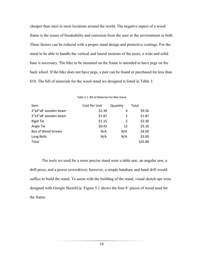
cheaper than steel in most locations around the world. The negative aspect of a wood
frame is the issues of breakability and corrosion from the user or the environment or both.
These factors can be reduced with a proper stand design and protective coatings. For the
stand to be able to handle the vertical and lateral motions of the users, a wide and solid
base is necessary. The bike to be mounted on the frame is intended to have pegs on the
back wheel. If the bike does not have pegs, a pair can be found or purchased for less than
$10. The bill of materials for the wood stand we designed is listed in Table 1:
Table 5.1: Bill of Materials for Bike Stand
Item Cost Per Unit Quantity Total
2"x4"x8' wooden beam $2.39 4 $9.56
2"x3"x8' wooden beam $1.87 1 $1.87
Rigid Tie $1.15 2 $2.30
Angle Tie $0.43 12 $5.16
Box of Wood Screws N/A N/A $4.00
Long Bolts N/A N/A $3.00
Total
$25.89
The tools we used for a more precise stand were a table saw, an angular saw, a
drill press, and a power screwdriver; however, a simple handsaw and hand drill would
suffice to build the stand. To assist with the building of the stand, visual sketch ups were
designed with Google SketchUp. Figure 5.1 shows the four 8’ pieces of wood used for
the frame.

20
Figure 5.1: 3 pieces of 2‖x4‖x8’, 1 piece of 2‖x3‖x8’
In order to build a stand with acceptable stability, a wide and strong base must be
constructed for the design. Two of the four 2x4 wooden beams are used for the base. One
beam is cut into two equal 4 foot pieces. The other wooden beam is cut twice. Once the
piece is cut into two 4’ sections, use one of the sections and cut it in half again to form
two 2’ sections. This gives us three 4’ sections, and two 2’ sections of wood. The two 2’
sections are laid down parallel to each other 4 feet apart, and one 4’ section is placed
parallel between the two pieces, with the piece about 1 foot away from the front 2’
section and 3 feet away from the back 2’ section. Then the two remaining 4’ sections are
laid on top of the three wooden boards perpendicularly across the two 2’ sections spaced
about the distance mid-peg to mid-peg of the bike to be mounted as depicted in Figure
5.2.

21
Figure 5.2: Mid-Peg to Mid-Peg Distance Defined
These pieces of wood are fastened together with 6 angle ties at each connecting point,
giving a base with the form shown in Figure 5.3.
Figure 5.3: Visual of the Bike Stand Base

22
Once the base is made, the vertical stands for holding the bike can be added to the
frame. These vertical pieces are two 2’ wooden sections cut from one of the remaining
2x4 wood beams. These two 2’ sections are mounted vertically over the cross section of
the two 4’ sections, and face each other, wide side out, perpendicularly. Two holes
slightly bigger than the peg’s diameter need to be drilled in the two wood sections, in
order to hold the bike in the stand. These holes need to be high enough to avoid the back
wheel from contacting the lower 4’ wooden section of the frame’s base. The two rigid
ties are used to connect the two vertical beams to the base of the frame. Figure 5.4
clarifies this layout.
Figure 5.4: Vertical beam placement on the bike stand base
Side stabilizers are imperative for the final frame design, as there is a great
amount of force put on the stand, from twisting and push-pull forces, when the user
pedals the bike. These side stabilizers are made from the remaining 2x4 wood. A 45°
angle needs to be cut at each end of the six stabilizing beams, to connect the stabilizers

23
from the base to the vertical posts. The angle ties are used to connect the stabilizing
beams from the base to the vertical posts. Figure 5.5 depicts the final frame design
showing the locations of the six stabilizing beams, as well as the approximate locations of
the peg holes and angle ties.
Figure 5.5: Completed back half of the bike stand
The main frame for the bike stand is now complete; however, a front wheel holder
must be constructed to hold the front tire in place. This will keep the user from turning
the tire and possibly shifting too much weight to one side of the stand. The front tire
holder is much easier to construct. Simply cut the 2x3 wooden beam into two 2’ sections,
and two 1’ sections. Place the two 1’ sections parallel to one another approximately 2 feet
apart. Lay the two 2’ sections on top of the 1’ sections perpendicular to the 1’ sections
and parallel to one another. The space between the two 2’ sections should be just a bit
wider than the width of the bikes front tire, in order to hold it tightly in place. Angle ties
are used to connect the pieces of wood together as Figure 5.6 demonstrates.

24
Figure 5.6: Front Tire Holder
Once the two sections of the bike stand are completed we can mount the bike and other
hardware such as a motor or alternator on the frame. A concept of the bike frame with a
bike is shown in Figure 5.7.
Figure 5.7: Final bike stand design with bike and alternator in place

25
The bike stand frame design was made to withstand a great amount of force from
the user and still maintain its performance and form. This is necessary in the bike to
allow the user to pedal much faster if more energy is required in a shorter amount of time.
While the stand does not have the strength of a steel stand, we believe the stand is more
than adequately meets the strain requirements from a user of average weight and size.
Another factor that needs to be addressed is the issue of corrosion. This bike is
intended to be used by people in developing and third world countries, so it is safe to
assume the entire system will be outside in the elements for the majority of its working
lifetime. Wood corrodes when left unprotected in the environment for an extended period
of time; however, there are many protective coatings for wood on the market that are
reasonably priced. A coat of lacquer and fresh paint should be more than enough to help
significantly increase the lifetime of the stand for outdoor use. If cost is too much of a
factor, the stand should still hold up quite well in an exposed environment if it is kept out
of direct contact with rain, water and other liquids.
While we believe our stand has high durability and stability for its given cost,
there are more than likely many improvements that can be made to the stand in order to
improve its quality to cost ratio. This would require extensive testing in a controlled
environment as well as extensive testing in an exposed environment; however, the scope
and limited time of our project did not permit us this opportunity. We do hope that
students in the future phases of the DC House project will look to improve upon our
current bike stand design.
26
Motor:
With a solid stand in place, a motor must be selected in order to create the DC
power to supply the DC House’s battery array. There are many options for the motor set
up for the system. These include a DC motor, a Generator, and an Alternator. We will
look to connect the spinning back wheel directly to the axel of motor’s rotor. The two
options are to either have direct contact between the back wheel and motor axel or to
have a belt connect the two elements. It was decided early on to use a belt to connect the
two elements together. While a belt adds more complexity to the set up and makes the
bike more difficult to remove from the stand, it gives much more grip between the wheel
and axel, reducing the slippage losses between the two parts. If a direct connection was
made the slippage losses could increase dramatically depending on how the user was
pedaling the bike and the external conditions at the time, such as the stand being in a wet
environment.
To connect the wheel to the motors axel, the bicycle tire and tube was removed. A
belt that fit nicely on the wheel rim was chosen and an axel head for the motor needed to
fit the belt as well. The next step was to determine the best motor to connect to the bike.
A simple DC motor was initially thought to be the best choice as the DC output of
the motor was the desired electrical output for the battery array. That meant components
would not need to be created or maintained to convert AC to DC and the losses from AC
to DC could also be avoided in the system. We searched for DC motors in common
household appliances such as vacuums and ceiling fans, but found no motors at the size
we wanted for the scale of the bicycle system. The sizes were too small and did not create
enough voltage or current to output a substantial amount of power. While looking into
27
buying a DC motor at a decent size and rating, it was found that the cost for such a motor
would be too expensive, and finding such motors in third world and developing countries,
much less buying them, would be out of the question for the scope of cost for this project.
Another motor option was using a car generator to produce the output DC voltage
for our system. Car generators are parts found on older models of cars before the 1960’s.
They are similar to alternators, but produce DC voltage directly without a use of a
converter like an alternator. This seemed a valid choice as once again the losses from AC
to DC conversion could be avoid; therefore, improving the efficiency of the bicycle
system. We looked for a car generator from an old car in order to test the part; however, it
soon became obvious that the part is very difficult to locate. There are very few cars left
that use car generators as opposed to car alternators and the ones that still exist are
usually very expensive or hard to find. When looking for a car generator from Los
Angeles to as far north as Bakersfield, we found no working car generators. The few that
were located were rusted beyond the repair we could provide. This was unfortunate
because we were not able to compare a car alternator to a car generator. It may have been
in vein nevertheless, if it was that difficult to find a car generator in California where
supplies are very abundant, it could be even more difficult to locate internationally in
poorer areas. The cost of a car generator could also pose a problem as older car
generators tend to cost more due to their rarity and the components they utilize. Car
generators use a component called a commutator to rotate the motors fields, which makes
the generators more costly and heavier. Due to the increased expense and less availability
compared to alternators, the car generator was ruled out for the system design.

28
Alternator:
The last practical option to implement for the bicycle system was to use a
standard car alternator. This seems to be the most reasonable motor for the design, as car
alternators are widely available worldwide for relatively low costs when purchased as a
used part. Finding donated alternators would also be an easier task to reduce the projects
overall cost. There are some difficulties however with an alternator as opposed to other
motor options. The first issue is the power loss due to conversion from AC to DC voltage.
Most alternators automatically convert AC to DC in the regulator of the part; however,
there is still the power loss in the alternator that will reduce the efficiency of the product
and waste some of the energy exerted by the user. Another major issue when using an
alternator occurs at the speed at which the part is operated. When a car is idling, the rpm
of the motor can be seen in the odometer. This value is usually around 600-700 rmps.
Alternators usually run at a 3:1 rpm ratio due to the diameter difference in the motor and
alternator head. This means an alternator is more efficient at speeds of 2000 rpms and
higher[3]. We could never hope to achieve this speed even with a bike tire being
somewhere around a 10:1 ratio of the alternator’s head diameter. If a user was to pedal
around a reasonable 100 rpms the alternator would only be rotating around 1000 rpms;
which is around half the speed of an idling car. For our testing and bike design, we used a
Ford 3G alternator. This part is readily available as it was used in a majority of Ford’s
cars for over a decade. Figure 5.8 shows the current output on the various models of the
3G alternator based on the shaft’s RPM.

29
Figure 5.8: Output Current vs RPM for Ford 3G Alternators[3]
As you can see, no matter which model of the Ford 3G alternator used, the output
current does not begin to reach its maximum potential until around 3000-4000 rpms.
Even though it would be physically impossible, we would never want to run the
alternator as such speed as the output current would be much too high for the rated
equipment used for the design.
There is one possible method to increase the current output at lower RPMs. This
process would require either the stator or rotor wiring to be rewrapped. The rewrapping
of the stator or rotor would have to be with thinner gauge wire in order to increase the
number of turns.

30
Figure 5.9: Display of the field producing parts, stator and rotor[4]
From the Figure 5.9, you can see it is much easier to rewrap the rotor instead of
the stator. The stator is a complex number of wired loops set up in a particular order to
produce an electromotive force (EMF) when charged so the rotor can produce an
electrical output. The difficulty with rewrapping the rotor is trying to remove it from the
finger poles. A more detailed picture of the rotor structure is shown in Figure 5.10
Figure 5.10: Diagram of rotor assembly in alternators[13]

31
The finger poles on the rotor actually bend the magnetic field of the rotor around the shaft
in order to obtain the electromagnetic induction between the rotor and stator that produce
the electrical power. This process produces a voltage across a conductor moving through
a magnetic field. In this cause, the rotor moving through the stators magnetic field that
causes the alternating current.
Once the finger poles and shaft are removed, the coil of the rotor can be rewound
with thinner wire more times. From Farraday’s equation, , we find that as
N (number of turns) increases, ε (electromagnetic force) increases proportionally[12].
With the higher EMF, we produce more power from less rotor rotations. In other words,
with a rewrapped rotor we can produce more power with lower RPMs; however, this will
not give the alternator any more power efficiency, it will only shift the Output Current vs.
RPM curve shown in Figure 5.8 to the left. While more current will be produced at lower
RPMs this is because the EMF is much bigger, which in turn will give the users another
problem, the EMF-produced resistance. An EMF in a motor is not a problem until you
are the one actually supplying the rotation of the shaft. A higher EMF means the user will
experience a higher resistance in their pedaling. This ―inductance hump‖ of starting to
pedal will tire the user greatly if a full field is being produced by the stator. To resolve
this issue a few different ideas were implemented to reduce the pedaling resistance in the
alternator.
32
DC Permanent Magnet Motor:
The first idea for deciding how to mitigate the EMF issue was to attach a DC
motor into the belt system between the back tire of the bike and the alternator head to
produce a DC voltage to apply to the stator. An alternator will not produce any current
unless the stator has a sufficient voltage and current to induce the EMF required to
interact with the rotor. The greater the voltage on the stator, the greater the EMF and
resistance the user will encounter. If a large voltage was applied to the stator via a battery
or voltage supply, the EMF could be strong enough to keep some users from even starting
to pedal the bike, inhibiting them from producing any power. The DC motor hooked up
to the same belt as the alternator would be a good way to regulate the stators EMF
depending on the pedaling speed of the user. When the user is not pedaling, no DC
voltage is being produced or provided to the stator of the alternator. This means there will
be no EMF resisting the user from starting the bike. As the user begins to pedal more
rapidly the DC motor will begin to produce a strong voltage to charge the EMF of the
stator. This means the strength of the field and resulting power output of the alternator
would be completely depend on the strength and speed of the user. This would allow
smaller, less capable individuals to still produce some small amount of power from the
alternator opposed to none, and stronger individuals would be able to avoid the initial
EMF field and build pedaling momentum to charge the EMF of the stator to its maximum
strength and allow for a higher amount of power output from the alternator for a longer
amount of time. We received a small DC motor from a previous power generating bike
stand to try implementing the process on our design. In order for the DC motor to be
viable for our system, the motor would have to supply enough voltage to the stator in

33
order to start the charging of the alternator. The DC motor was tested individually in a
motors lab to determine the output power of the part. The motor was connected to an
induction motor that was controlled by a Variable Frequency Drive. With this VFD, the
DC motor was tested at various RPMs to determine the output current and voltage. We
would want a maximum voltage of around 12V and a maximum current around 1A to
charge the stator and produce a strong EMF for the alternator. Once the motor data was
collected, it was clear that the DC motor we were using would not provide a strong
enough DC voltage to stator to induce the EMF at the operating RPMs of our system.
Basically, the user would have to pedal so quickly to induce the EMF of the alternator
from the DC motor, that the use of the motor to power the stator field is unreasonable.
Figure 5.11: Output Voltage vs. RPM of DC Motor
The method of using a DC motor as a field generator on the design is still
feasible; however, it would take a bigger and more expensive DC permanent magnet
motor to implement, and the main goal of this project is to keep the costs as low as

34
possible. So we determined the improvement of negating some issues of the EMF in the
alternator was not worth the cost of the DC motor.
Another way to possibly reduce the EMF of the alternator to allow for easier
pedaling is simply connecting in series a string of power resistors. This is the same
technique used by car designers when connecting the alternator.
Figure 5.12a: Wiring of Alternator[14] Figure 5.12b: Wiring of an Alternator in a Car[5]
Figure 5.12a shows that the field wire (green wire) is connected in series with a
warning light, or charge lamp, and a resistance in parallel with the lamp. This resistance
needs to be determined quite precisely. Too low of a resistance and the user would still
have the issue of trying getting over the ―induction hump‖ of the electromotive force and

35
start pedaling the bike. Too high of a resistance, and the alternator would never turn itself
on at low RPMs expected from the users on the bike [6].
Figure 5.12b shows the standard wiring of our Ford 3G alternator in a car. From
the highlighted blue section in the top right, a resistance of around 550Ω seems to be the
choice amount. Based off this number, we tested in the lab the optimal resistance to
connect in series with the field wire. We used multiple 100Ω adjustable power resistors
in parallel from the motors lab for testing. We found the actual resistance needed on the
field wire is much lower than the resistance used in a car. The resistance for the field wire
seemed the best balance for the EMF field of the alternator at 4-8 ohms. The car uses a
much higher resistance because the faster RPM of the car will be high enough to induce
the EMF in the alternator. The RPM rates a user would pedal at would not be fast enough
to induce the EMF of the alternator with such a high resistance on the field wire. More
data on the field resistance is shown in Test & Planning section as well as the Mounting
& Wiring section.
Mounting & Wiring:
In order for the alternator to produce power, it must be securely fastened to the
stand and connected correctly to the bike and all other components. Alternators are very
durable when connected correctly, but if connected incorrectly the alternator can be
destroyed very quickly and pose a serious injury threat to everyone around the system.
To mount the alternator on the bike frame, two pieces of remaining 2‖x3‖ wood
can be used to secure the alternator. The Ford 3G alternator has three mounting holes;
two on one side and one on the other. The alternator can be laid on top of the two cross
sections of wood across the back of the bike stand. The holes can then be marked and

36
drilled with a 3/8‖ bit. Three 3/8‖ 3‖ bolts and screws can be used to then thread and
secure the alternator to the pieces of mounting wood. These cross pieces of wood can
now be attached to the back of the stand with remaining angle ties from the construction
of the bike stand. It is recommended to first attach the pulley belt from the back tire to the
alternator head. Once they are connected, pull the alternator and attached pieces of wood
back until no slack is left in the belt. The belt must be tight between the two mediums in
order to reduce any belt slippage and slippage losses when the user pedals. Once the belt
is tight, mark the angle tie locations to connect the mounting wood pieces to the bike
stand firmly. A rough view of the mounting position can be viewed in Figure 5.13 and a
view of the connection between the alternator shaft and bicycle rim in Figure 5.14.
Figure 5.13: Mounting Alternator to Stand Figure Figure 5.14: Pulley Connection Between Alternator and Rim.
The direction in which the alternator is oriented to spin does not affect its output power.
The alternators rotor can be rotated either clockwise or counterclockwise and achieve the
same output values, as we found out by an initial setting up the alternator backwards.
Once the pulley belt is connected between the bikes back tire rim and alternator
head, and the alternator is mounted, the alternator must be wired to output DC power.

37
The three connections to be made, as shown in Figures 5.12, are the output wire, field
wire, and regulation wire. A simple battery charging connection is shown in Figure 5.15.
Figure 5.15: Battery Charging System Wiring.
In Figure 5.15, the alternator has three output wires labeled 1, 2, and BAT. The
wire labeled BAT is obviously the output of the alternator that is used to charge the
battery or to power an external load instantaneously. The wire labeled 1 is the field wire.
The field wire feeds current and voltage into the stator of the alternator to create an EMF
to produce the output DC power as described earlier in the report. A resistor and switch
are placed in series between the alternator and battery. Both of these components are used
to protect the alternator. The switches purpose as stated by Eagle and Olding, ―It is
equally important – perhaps even more so, actually – that the field coil wire not be
attached directly to the battery’s positive terminal. In a car, the field coil is connected to a
switch, a small warning light, and then the battery’s positive terminal. The switch isolates

38
the battery from the field coil when not in use. This is important, as otherwise the battery
will run itself down powering the field coil when the alternator is not operating. Some
kind of switch should always be wired up in between the field connection and the
battery.‖[6] The field will always pull current and voltage from the battery, regardless of
whether the alternator is running or not. Without a disconnect, the battery would be dead
before it is needed to excite the field when the alternator is actually running. The resistor
is used to protect the field from over-amperage that could damage lesser quality
alternators [6]. Without a resistor in series, the battery can output 14 volts and up to 6
amps to the field. Not only will this amount of power into the field possibly damage the
alternator, it will also create a very large EMF that would make human pedaling of the
rotor almost impossible due to the great resistance. As stated earlier, too low of a
resistance and the user would still have the issue of trying getting over the ―induction
hump‖ of the high EMF and pedal the bike; too high of a resistance, and the alternator
would never turn itself on at low RPMs expected from the users on the bike due to the
low EMF[6]. The wire labeled 2 on the alternator diagram in Figure 5.15 is the regulation
wire. This wire is usually hooked up directly to the positive terminal of the battery. It
senses the voltage on the line and compares the output voltage to this sensed voltage. It
creates a feedback in the alternator controller that regulates the output of the alternator.
One of the main objectives of this project is to produce a 24 volt DC output to charge an
array of batteries. This would require a DC-DC converter at the back end of the alternator
to produce this; however, it was determined through testing that we could take advantage
of the alternator’s regulation wire to output 24 volts directly. If the regulation wire is
hooked up to a voltage source with the desired DC output, the output of the alternator

39
will be regulated to this voltage source. This only goes to a certain point that the
alternator is rated to go. In our case, we were able to regulate the output up to 22V on the
Ford 3G alternator. This is a much cheaper and simpler option to obtaining a 24 volt DC
output, rather than buying an expensive DC-DC converter to accomplish the same goal.
In summary, the field wire of the battery must be connected to a certain resistance
and switch to protect the alternator, and battery and make human pedaling of an
alternator possible. Also the regulation wire can be used to manipulate the desired output
voltage of the alternator up to a certain voltage limited by the rating of the specific
alternator. Finally, the alternator must be mounted in such a way to both hold the
alternator firmly, and create a strong tension between the alternator and back wheel to
avoid excess slippage losses.

40
VI. Integration & Testing:
Integration & Cost:
The integration process for this project is relatively simple and a majority of it has
been covered in detail in the design section. The first step of integration was securing the
bike into a stable stand for the system. Bikes are not easy objects to stabilize as they are
very sleek and have no obvious places to hold and secure. In order to find a way to secure
the bike, the idea of placing pegs on the back of the bike was found as the best solution.
The pegs had to be cut so that the bolt was flush to its end otherwise our axel did not
offer enough thread to screw the pegs on. To hold the bicycle in the designed wood stand,
we installed common bicycle pegs so the rear axle would protrude outside of the frame of
the bicycle. Holes were then drilled into the wood and the pegs were inserted into the
drilled holes. The boards stranding upright containing the pegs were braced in all
coordinate directions. The stand was extended backwards to allow for motor mounting
positions. This allowed for any possible belt sizes; furthermore, for added safety a small
brace was built for the front wheel so that any torsion would not occur. The front wheel
was rendered stationary.
Mounting the motor was the next part of the integration. This was relatively
simple as two pieces of 2‖x 3‖ wood were tied to the frame and the alternator was bolted
to the mounting wood accordingly. The alternator had to be positioned at the right distant
back from the bike to give a strong enough tension on the belt to avoid excess slippage
losses from pedaling.

41
The battery and resistors had to be wired and integrated with the alternator in
order to complete a system that could charge a battery according to the standards set in
the requirement section of the report.
Also stated in the requirement section of the report was the absolute necessity of
the power generation bike system being as cheap as possible in order for it to be
financially viable for the DC House project. Table 6.1 shows a list of various parts and
equipment that were necessary for the completion of our entire project.
Table 6.1: Estimated and Actual Costs of Project
The actual amount of money spent on this project was very low thanks to
generous donations and available equipment accessible to students at Cal Poly. The
alternator and pulley belt were donated by Howard Siewert, a mechanic in Northern
California. The bicycle, battery, power resistor, and wires were all equipment that was
able to borrow from Cal Poly and Cal Poly students in order to test and demonstrate our
project.

42
While donations are possible and would be beneficial to the DC House’s success,
an estimated cost table was made to estimate the total cost of our design excluding any
donations. All the estimated costs were researched by calling local scrapyards, shops, and
average prices from retailers during the building process. The estimated cost is still
within a respectable cost range of just over $200.00. The cost is very respectable for the
scope of the system with the majority of the cost due to the battery; however, the battery
is not an intrinsic cost of only our system, but rather the entire DC House project. The
battery array will be charged by the various other sustainable systems, and be considered
split cost between all DC House projects. This drops the total cost of the power
generation bike system even lower.

43
VII. Tests & Planning:
Planning:
The test plans for the power generating bike include laboratory testing and field
testing. We had two sizes of Ford 3G alternators available for the project: the 95 amp
model and the 130 amp model. The nominal current outputs for the two types can be seen
in Figure 5.8. We used the 95 amp alternator in laboratory testing and the 130 amp model
was attached to the bike stand. The available DC motor was also testing in the laboratory
to determine its output characteristics based on RPM.
In order to be able to record accurate data for the alternator we decided to use an
induction motor as a prime-mover in the laboratory. The motor was run by a Variable
Frequency Drive (VFD), which allows for precise control over the RPM of the alternator
in order to understand the outputting characteristics of the motor based on the RPM. This
also has the added benefit in we could measure the input power and hence calculate the
efficiency of our alternator. The basic bench set up to record data for the 95 amp Ford 3G
alternator is shown in Figure 7.1. The DC motor was testing in the same manner as the
alternator for laboratory testing.
Figure 7.1: Alternator Bench Setup

44
The testing in the field, with the bicycle setup, was less accurate but just as
important of information. The field setup was running the 130 amp alternator attached to
the bicycle stand and wired to the components accordingly to the wiring section. A
simple bicycle RPM meter can be connected to the back wheel of the bicycle. If you
multiply the RPM measured by 10, we receive the approximate RPM of the alternator
shaft. This multiplication is the result of the 10:1 diameter ratio between the bike wheel
and alternator head. The bike diameter measured 24 inches while the alternator head
measured less than 2.5 inches, which gives us the said 10:1 ratio. The issue with running
a field test for the alternator current output is the difficulty of the peddler to hold a
constant pedaling rate with the varying EMF strength and other external conditions.
Testing:
The results of the alternator in the laboratory were very similar to the expected
data for the 95 amp Ford 3G alternator. There were two factors to determining the output
of the alternator: the RPM and the field resistance. The field resistance effect on the
output current proved quite linear at high RPMs, while at RPMs lower than 1200 a
resistance about 10 ohms kills nearly all of the current output and a resistance under 4
supplies an excess amount of current to the field. A resistance between 5-8 ohms proved
to be the optimal field resistance when in the human pedaling RPM rate, between 0-1500
RPM, which is much lower than a car’s standard RPM rate.
The RPM of the alternator proved to be the more important of the two
determining factors. The field current, regardless of the current, generates no output
power if the RPM rate is too low. We tested the alternator through various RPM values

45
with a 4 ohm field resistor attached. The data received and the calculated values of
efficiency are shown on Table 7.1.
Table 7.1: Output Current based on RPM for Ford 3G Alternator
The voltage vs. the RPM proves to be completely unchanging as expected, due to the
regulation of the alternator’s controller. The regulation wire was connected to the
battery’s positive terminal which regulated the output voltage to 12.8 V, shown in Figure
7.2.
Figure 7.2: Voltage Output based on RPM of Ford 3G alternator
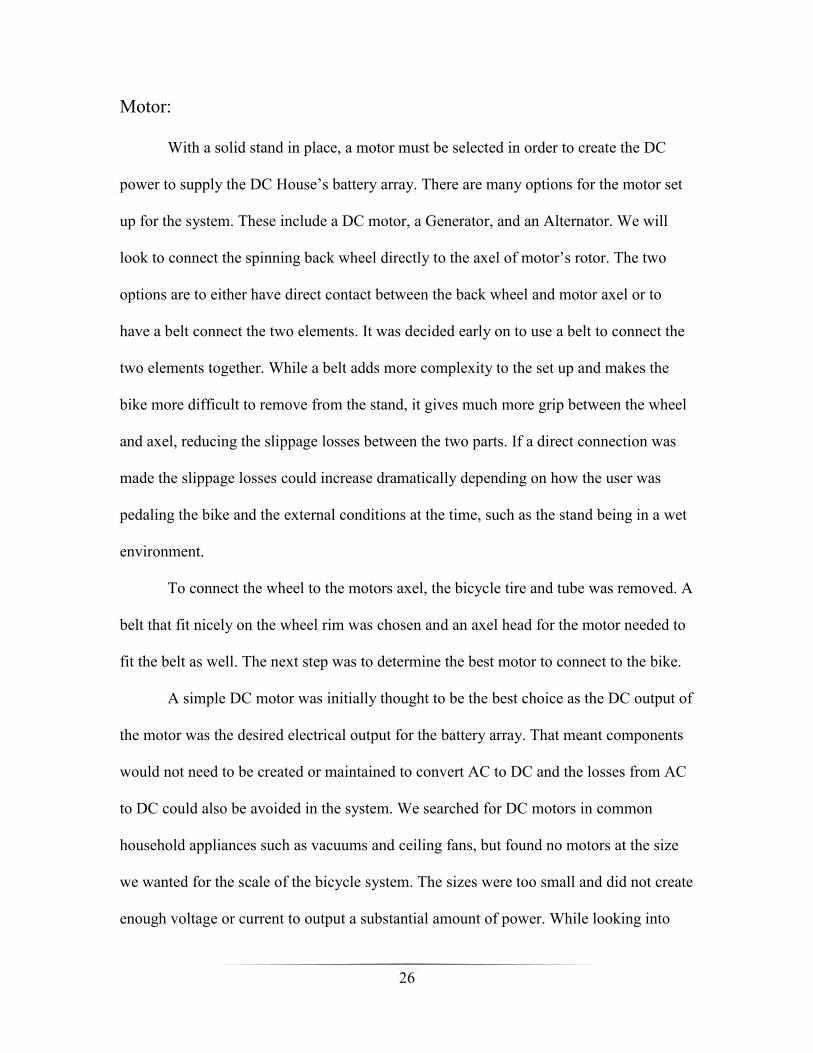
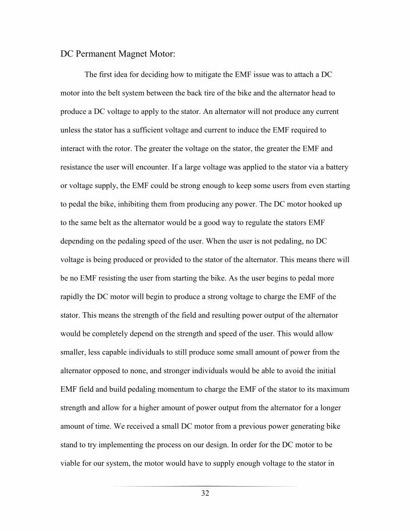
The current output vs. the RPM of the alternator is very similar to the expected data of
shown in Figure 4. The output current is minimum until around 1200 RPM. Once that
RPM rate is surpassed, the output current increases greatly. The resulting graph can be
seen in Figure 7.3.
0
5
10
15
0 1000 2000 3000
Volts vs RPM
volts
46
Figure 7.3: Current Output vs RPM
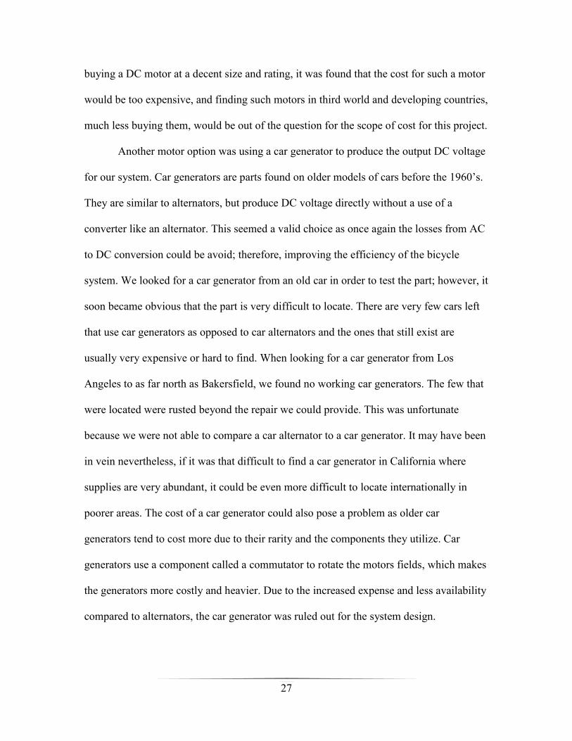
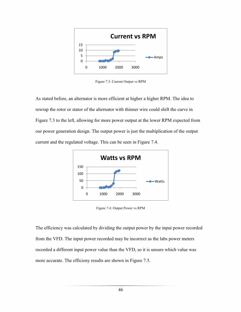
As stated before, an alternator is more efficient at higher a higher RPM. The idea to
rewrap the rotor or stator of the alternator with thinner wire could shift the curve in
Figure 7.3 to the left, allowing for more power output at the lower RPM expected from
our power generation design. The output power is just the multiplication of the output
current and the regulated voltage. This can be seen in Figure 7.4.
Figure 7.4: Output Power vs RPM
The efficiency was calculated by dividing the output power by the input power recorded
from the VFD. The input power recorded may be incorrect as the labs power meters
recorded a different input power value than the VFD, so it is unsure which value was
more accurate. The efficieny results are shown in Figure 7.5.
0
5
10
15
0 1000 2000 3000
Current vs RPM
Amps
0
50
100
150
0 1000 2000 3000
Watts vs RPM
Watts

47
Figure 7.5: Efficiency of alternator vs RPM
From extensive testing with the system design, we received similar results from
the laboratory data. For the field testing, a 130 amp Ford 3G alternator was used. The
curve from Figure 5.8 shows the alternator produces higher currents at lower RPMs
which seemed to be the case for testing.
A 7 ohm field resistor was used in field testing in order to allow for easier
pedaling by the users. When pedaling at an easy pace of about 1000 RPM at the
alternator shaft, we were recieveing 14 volts regulated out and 1 to 1.5 amps. This gives a
power output from 14-21 watts when pedaling at an easy pace. A user was able to
produce an RPM of 1500 at the alternator shaft, with 15 voltage at around 3.4 amps. This
gave a respectable 51 watts of power output; however, the pace would be hard to sustain
for any lenghty amount of time.
As shown early in the DC motor section in Figure 5.11, the output voltage vs
RPM of the DC motor proved to be linear. The current was low, never passing 1.5 amps.
This power output of the DC motor would not have been enough to charge the stator field
of the alternator as previously desired. A larger DC motor could have possibly supported
the alternator field current at lower RPMs; however, the cost of such a motor would not
have been finacially viable.
0
10
20
30
40
0 1000 2000 3000
efficiency vs RPM
% efficiency
48
VIII. Conclusion:
Through research and testing, this project aimed to design and implement a first
phase of sustainable energy resources for the DC House Project. The project goal was to
supply a battery array with a 24 volt DC output. This goal had to be met within the
constraints of a low production cost and high safety. The project had to offer a durable
product with relatively good efficiency. We believe we accomplished this goal. The
project results were conclusive with the alternator as an energy provider. Alternators are
great tool when running at a high RPM, but less efficient when running at a lower RPM,
like that provided by users pedaling the bike. There are many other options to explore to
find the most efficient way of producing DC power from a bicycle, but we believe
modifying an alternator is the most cost effective way to reach that goal. Unfortunately,
the scope of time for our project did not allow for rewiring an alternator to test for the
power output improvements at lower RPMs; however, we hope that students in the next
phase of the DC House Project will be able to offer their time to try this improvement, as
well as other ideas. The bike stand and coupling between bike and motor have room for
improvement as well like to reduce torque and tension to the stand and reduce slippage
between the belt coupling. Further stress tests over a longer period of time would also be
beneficial in order to determine the actual average lifetime of our product, and if the cost
of production is worth the provided power within that lifetime.
Our greatest difficulty came with wiring the alternator correctly to run on our bike
system. The field resistor has to be set to a very specific resistance to find the perfect
strength of the EMF in the alternator to provide a high power output and low pedaling

49
resistance. More testing can be done in the motors laboratory to find this range of
resistances based on the generated RPM rate of the users.
The cost of the bike stand was relatively low compared to many other sustainable
energy sources. The cost is just about $200.00, when including a new battery; however,
when the battery cost is excluded, the system is closer to $140.00 to produce. This cost
would only decrease, if parts and equipment were bought in higher quantities for mass
production. We believe our design is a great start in developing a low cost, low upkeep
device that will allow power production whenever the user desires. Without access to
power anything we can provide to the less fortunate people of the world will help. Our
system along with solar, wind, and hydroelectric systems will help provide power for DC
House users to run simple appliances like lights, medical equipment, and fans that so
many of us take for granted on a daily basis.

50
Bibliography:
[1] International Energy Outlook 2010. July 2010. U.S. Department of Energy. May
2011. http://www.eia.doe.gov/oiaf/ieo/world.html
[2] Key World Energy Statistics. 2010. International Energy Agency. May 2011.
http://www.iea.org/textbase/nppdf/free/2010/key_stats_2010.pdf
[3] Ford Fuel Injection. 2010. Ford Fuel Injection. May June 2011.
http://www.fordfuelinjection.com/index.php?s=2g&submit=SEARCH
[4] C15 Alternator Wiring. Cedric Norman. 2011. Alternator Wiring. June 2011.
http://www.classicmotorcycles.org.uk/c15/c15_alternator_wiring.htm
[5] 3G alternator, Mini Starter, and Battery Relocation. Tim65GT. July 2009.
StangNet.com. June 2011. http://www.stangnet.com/mustang-forums/789578-3g-
alternator-mini-starter-battery-relocation.html
[6] Nepal Ghatta Project. Eagle, Nathan; Olding, Benjamin. 2000. MIT. May 2011.
http://web.media.mit.edu/~nathan/nepal/ghatta/index.html
[7] The DC House Project. Taufik. 2010. Cal Poly. Feb. 2011.
http://www.calpoly.edu/~taufik/dchouse/index.html
[8]Cote, Alan. "How efficient is a bicycle?" Bicycling Sept. 2005: 40. Expanded
Academic ASAP. Web. 26 May 2011.
[9]Ke, Yu-Lung, Ying-Chun Chuang, and Hung-Shiang Chuang. "Energy Recovery
Electric Bicycle with Two-quadrant DC Motor Drivers." Conference Record - IAS
Annual Meeting (IEEE Industry Applications Society), ISSU.PAGE (2009)
[10]"PEDAL POWER." Scholastic Choices 25.6 (2010): 3. Academic Search Elite.
EBSCO. Web. 26 May 2011.
[11]Tiwari, P. , Gite, L. , Shrivastava, A. , & Pandey, M. (2011). Pedal power for
occupational activities: Effect of power output and pedaling rate on physiological
responses. International Journal of Industrial Ergonomics, 41(3), 261-267
[12] Alexander, Charles; Sadiku, Matthew (2007). Fundamentals of Electrical Circuits,
Third Edition
[13] Keyword Pictures. June 2011.
http://www.keywordpicture.com/keyword/rotor%20diagram/
[14] Bobs Garage. June 2011. http://www.bobsgarage.110mb.com

51
Appendices:
Gantt Chart:

52
Bill of Materials:


