OWNER'S MANUAL - carid.com · OWNER'S MANUAL BAMF800/2 ... INTRODUCTION Power Acoustik amplifiers...
21
************* OWNER'S MANUAL BAMF800/2 BAMF1250/2 BAMF1800/2 BAMF2200/2 BAMF2600/2 BAMF1200/4 BAMF1600/4 BAMF2000/1D BAMF4000/1D BAMF5500/1D
Transcript of OWNER'S MANUAL - carid.com · OWNER'S MANUAL BAMF800/2 ... INTRODUCTION Power Acoustik amplifiers...

************* OWNER'S MANUAL
BAMF800/2 BAMF1250/2 BAMF1800/2 BAMF2200/2BAMF2600/2 BAMF1200/4 BAMF1600/4
BAMF2000/1D BAMF4000/1D BAMF5500/1D

INTRODUCTIONPower Acoustik amplifiers provide high-performance sound reinforcement for your mobile audio equipment. Its versatility enables compatibility with optional Equalizers, Frequency Dividing Crossover Networks, and other audio processors in a customized system. The Multi-Mode bridging capabilities allow flexibility in hosting several different speaker configurations.To achieve optimum performance, it is highly recommended that you read this Owners Manual before beginning installation.
WARNINGHigh powered audio systems in a vehicle are capable of generating "Live Concert"high levels of sound pressure. Continued exposure to excessively high volume soundlevels may cause hearing loss or damage. Also, operation of a motor vehicle whilelistening to audio equipment at high volume levels may impair your ability to hearexternal sounds such as; horns, warning signals, or emergency vehicles, thuscontributing to a potential traffic hazard. In the interest of safety, Power Acoustikrecommends listening at lower volume levels while driving.

Before beginning the installation, consider the following:1. Do you plan to add additional mobile electronics equipment in the future?If you plan to expand your system by adding other components sometime in thefuture, ensure adequate space is left and cooling requirements are met.
2. Should you use high or low level inputs?Your Amplifier has been designed to accept Low-Level(Pre-Amp outputs from yourradio) source signal. If your radio/source is equipped with Pre-Amp outputs, it ispossible to utilize them to drive the Amplifier and the 2 front speakers. Then, use thebuilt-in power of your radio to drive the 2 rear speakers.
3. Are your components matched?The RMS power rating of your speaker(s) must be equal or greater than the RMSpower rating of your amplifier. Your speaker(s) also must be 2 - 8 Ohms impedancefor stable amplifier operation. Impedance information is normally printed on thespeaker basket or magnet.
4. Where will the amplifier be installed?Consider both the length of your leads, and routing when determining the mountinglocation. It is best to run power and RCA wiring on opposite sides of the vehicle toprevent induced noise. Pre-amp input jacks require a length of high quality shieldedmale to male RCA patch cord.
PLANNING YOUR SYSTEM

CONNECTING THE POWER (Fig.1,2)CAUTION: AS A PRECAUTION, DISCONNECT THE POWER WIRE FROM THE BATTERY WHILE MAKING THE POWER AND GROUND CONNECTIONS TO THE AMPLIFIER.
4/8 GAUGE(Thicker if planning for additional Amplifiers) wire is recommended for both the power and ground wires. 12 Gauge, for the remote turn-on wire. Both types are available at most Mobile Audio Dealers or Installation Shop.
(1) Ground : To Vehicle ChassisTo avoid unwanted ignition noise caused by ground loop, it is essential that the Amplifier be grounded to a clean, bare, metal surface of the vehicle's ChassisNOTE : GROUND WIRE SHOULD NOT BE EXTENDED MORE THAN 3 FT. (1 METER).
(2) +12 Volt(Fused) Constant Power: To Battery (+)Due to the power requirements of the Amplifier, this connection should be made directly to the positive (+) terminal of battery. For safety measures, install an in-lineFuse Holder (not included) as close to the battery positive (+) terminal as possible with an ampere rating; not to exceed total value of fuses in Amp.
(3) Remote Turn-On Input: To remote turn-on output of Car Stereo This Amplifier is turned "ON" remotely when the vehicle's stereo is turned "ON".NOTE : IF YOUR RADIO DOES NOT HAVE A +12 VOLT OUTPUT LEAD WHEN THE RADIO IS TURNED ON, THE "REMOTE" TERMINAL ON THE AMPLIFIER CAN BE CONNECTED TO VEHICLE'S ACCESSORY CIRCUIT THAT IS LIVE WHEN THE KEY IS "ON".


PANEL LAYOUT

PANEL LAYOUT

CONTROL FUNCTIONS
1. RCA input jacksThese RCA input jacks are for use with source units that have RCA or Line leveloutputs. A source unit with a minimum level of 200mV is required for proper operation.The use of high quality twisted pair cables is recommended to decrease the possibilityof radiated noise entering the system.
2. GAIN ControlThe level control will match the amplifiers sensitivity to the source units signal voltage.The Operating range is 200mV minimum to 6V maximum.
CAUTION: Do not run the amplifier in high volume for long time, otherwise the loudspeakers will bedamaged.
3. Full pass x-over switchWhen the switch is in the "Full" position, the full range is bypassed.
4. Low pass x-over switchWhen the switch is in the "LPF" position, frequencies lower than the low pass frequencysetting are passed.
4.1 Low pass x-over frequency controlThis control is used to select the desired low pass x-over frequency.BAMF800/2, 1250/2, 1800/2, 2200/2, 2600/2, 1200/4, 1600/4 : The frequency can beadjusted between 30Hz and 250Hz. BAMF2000/1D, 4000/1D, 55001D : The frequency can be adjusted between 40Hz and200Hz.
5. High pass x-over switchWhen the switch is in the "HPF" position, frequencies higher than the high passfrequency setting are passed.
5.1 High pass x-over frequency controlThis control is used to select the desired high pass x-over frequency. BAMF800/2, 1250/2, 1800/2, 2200/2, 2600/2, 1200/4, 1600/4 : The frequency can beadjusted between 50Hz and 500Hz.
6.Bass EQBAMF800/2, 1250/2, 1800/2, 2200/2, 2600/2, 1200/4, 1600/4 : The boost can beadjusted between 0dB to12dB. BAMF2000/1D, 4000/1D, 55001D : The boost can be adjusted between 0dB to 18dB.
7. Auxiliary outputsThe Auxiliary outputs offer Power Acoustik amplifiers easy, unlimited system expansion.Route RCA's from the line out of the first amplifier to the line input of a secondamplifier when using a single source output.

CONTROL FUNCTIONS
8. SUBSONICBAMF1250/2, 1800/2, 22200/2, 2600/2 : The frequency can be adjusted between 15Hzand 50Hz. BAMF2000/1D, 4000/1D, 5500/1D : The frequency can be adjusted between 20Hz and50Hz.
9. REMOTEControls the subwoofer amplifier gain, from a remote location for ease of adjustmentduring listening.Warning: Do not connect a level control knob from other manufacturers to the Remote Sub LevelControl of any amplifier. Even though the connectors fit properly, the control knob and connectorpin positions may be different and the amplifier will be damaged.
10. PHASE0°or180° selectable for switching the phase of the output to the woofer.
11. MASTER/SLAVE MODE[BAMF2000/1D, 4000/1D, 5500/1D]Controls whether the amplifier is a slave or master when connected in combinedamplifier configurations. (Refer to the Master Mode section of this guide.)All of the controls will be adjusted by the "Master" amplifier.-Slave mode : To be switched " Slave mode" when linking one amplifier with anotheramplifier.-Master mode : To be switched " Master mode" when only using this single amplifier.
12. INPUT MODESelects 2, 3 or 4 channel operation(FIG. 1)
13. GNDConnect this terminal directly to the sheet metal chassis of the vehicle, using theshortest wire necessary to make this connection. Always use wire of the same gaugeor larger than the (+)12 volt power wire. The chassis connection point should bescraped free of paint and dirt. Use only quality crimped and/or soldered connectorsat both ends of this wire. Warning : Do not connect this terminal directly to the vehicle battery ground terminal or any otherfactory ground points.
14. Remote Turn OnThis terminal turns on the amplifier when (+)12 volt is applied to it. Connect it to theremote turn on lead of the head unit or signal source.
15. (+)12 Volt PowerConnect this terminal through a FUSE or CIRCUIT BREAKER to the positive terminal ofthe vehicle battery or the positive terminal of an isolated audio system battery.Warning: Always protect this power wire by installing a fuse or circuit breaker of the appropriatesize within 12 inches of the battery terminal connection.

FIG. 1
CONTROL FUNCTIONS
16. FUSEThese fuses protect the amplifier against internal electrical damage and are meant toprotect the amplifier only. All other power connections should be fused at the source.
BAMF800/2 : 25A X 1 BAMF1250/2 : 20A X 2 BAMF1800/2 : 20A X 3
BAMF2200/2 : 20A X 4 BAMF2600/2 : 25A X 4
BAMF1200/4 : 25A X 2 BAMF1600/4 : 25A X 2
BAMF2000/1D : 40A X 2 BAMF4000/1D : 40A X 3 BAMF5500/1D : 40A X 5
17. SPEAKERSConnect subwoofers to these terminals.
18. LEDWill illuminate GREEN to indicate the amplifier is on and operating normally, and willbe illuminated RED if the amplifier shuts down due to short circuit, DC offset, oroverheating detected by on board protection circuitry

FIG. 2 MASTER MODE CONFIGURATIONBAMF 2000/1D, BAMF 4000/1D
1.Lowest Recommended Impedance is 1ohm mono.2.RCA Inputs are connected to both Left and Right channels3.Gain controls to be set match input source4.Line Output configured for stereo operation

FIG. 3 STRAPPED CONFIGURATIONBAMF 2000/1D, BAMF 4000/1D
2-4ohms
STRAPPED CONFIGURATION
1.Lowest Recommended Impedance is 2ohm Stereo2.RCA Inputs are connected to both Left and Right channels3.Gain controls to be set match input source4.Line Output is configured summed bridged which is ideal for subwoofer applications

FIG. 4 MASTER MODE CONFIGURATIONBAMF5500/1D
1. Lowest recommended impedance is 1 Ohm Mono.2. RCA Inputs are connected to both left and right cnannels.3. Gain control is to be set to match input source.

2-4ohms
STRAPPED CONFIGURATION
FIG. 5 SLAVE MODE CONFIGURATIONBAMF5500/1D
1. All of the controls can be adjusted only in "MASTER" mode amplifier.2. Lowest recommended impedance is 2 Ohm Mono.3. RCA Inputs are connected to both left and right cnannels.4. Gain control is to be set to match input source.
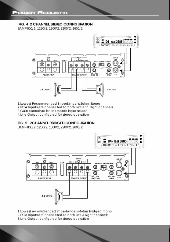
FIG. 4 2 CHANNEL STEREO CONFIGURATION BAMF 800/2, 1250/2, 1800/2, 2200/2, 2600/2
FIG. 5 2CHANNEL BRIDGED CONFIGURATION BAMF 800/2, 1250/2, 1800/2, 2200/2, 2600/2
1.Lowest Recommended Impedance is 2ohm Stereo2.RCA Inputs are connected to both Left and Right channels3.Gain controls to be set match input source4.Line Output configured for stereo operation
1.Lowest recommended impedance is 4ohm bridged mono2.RCA Inputs are connected to both Left &Right channels3.Line Output configured for stereo operation

FIG. 6 2CHANNEL TRI MODE CONFIGURATIONBAMF 800/2, 1250/2, 1800/2, 2200/2, 2600/2
1.Lowest Recommended Impedance is 4ohm Stereo2.RCA Inputs are connected to both Left and Right channels3.Output configured for stereo operation

FIG. 7 4CHANNEL STEREO CONFIGURATION BAMF 1200/4, BAMF 1600/4
1.Lowest Recommended Impedance is 2ohm Stereo2.RCA Inputs are connected to both Left and Right channels3.Gain controls to be set match input source4.Line Output configured for stereo operation

FIG. 8 4CHANNEL BRIDGED CONFIGURATION BAMF 1200/4, BAMF 1600/4
1.Lowest recommended impedance is 4ohm bridged mono2.RCA Inputs are connected to both Left &Right channels3.Line Output configured forstereo operation

FIG. 9 4CHANNEL TRI MODE CONFIGURATION BAMF 1200/4, BAMF 1600/4
1CH4-8 Ohms
WOOFER
2CH4-8 Ohms
3CH4-8 Ohms
4CH4-8 Ohms
WOOFER
1.Lowest Recommended Impedance is 4ohm Stereo2.RCA Inputs are connected to both Left and Right channels3.Output configured for stereo operation

TROUBLE SHOOTING GUIDE
Check fuses in amplifier.Be sure Turn-on lead is connected
Repair power wire or connections
Check connections to radio
Check fuse
Inspect for short circuit or anopen connection.
Reverse Left and Right RCA inputs to determine if it isoccurring before the amp.Check Tuner/Deck volume level.Clean contacts on fuse holders.
Be sure proper speakers are usedto ensure impedancerecommendations are observed.(If you use an Ohmmeter to check speaker resistance, please remember that DCresistance and AC impedancemay not be the same.)
NO SOUND
AMP NOT SWITCHING
ON
NO SOUNDIN ONE
CHANNEL
AMPTURNING
OFFMEDIUM/
HIGHVOLUME
SYMPTOMS CHECK POINTS CURE
Is the powerLED illuminated?
No power to power wire
No power to remotewire with receiver on
Fuse broken
Check speaker leads
Check audio inputleads
Check speaker loadimpedance

MODEL#MAXIMUM POWER
OUTPUTPOWER OUTPUT
@4Ohm POWER OUTPUT
@2OhmBRIDGED POWER
THD FREQUENCY
RESPONSE -1.0dBHPFLPF
SUBSONIC FILTERBASS EQ
ADJUSTABLE SENSITIVITY RANGEINPUT IMPEDANCE
(LOW LEVEL)FUSE
DIMENSION(D x W x H inch)
BAMF800/2
800W
150W x 2CH
180W x 2CH360W x 1CH
0.02%
10Hz-30kHz50Hz~500Hz30Hz~250Hz
-0dB ~ 12dB
0.2V~6V
10k Ohms25A x 118.7" x
8.26" x 2.16"
BAMF-1250/2
1250W
220W x 2CH
280W x 2CH560W x 1CH
0.02%
10Hz-30kHz50Hz~500Hz30Hz~250Hz15Hz~50Hz0dB ~ 12dB
0.2V~6V
10k Ohms20A x 211.37" x
8.26" x 2.16"
BAMF1800/2
1800W
300W x 2CH
380W x 2CH760W x 1CH
0.02%
10Hz-30kHz50Hz~500Hz30Hz~250Hz15Hz~50Hz0dB ~ 12dB
0.2V~6V
10k Ohms20A x 313.77" x
8.26" x 2.16"
BAMF2200/2
2200W
370W x 2CH
450W x 2CH900W x 1CH
0.02%
10Hz-30kHz50Hz~500Hz30Hz~250Hz15Hz~50Hz0dB ~ 12dB
0.2V~6V
10k Ohms20A x 414.96" x
8.26" x 2.16"
BAMF2600/2
2600W
450W x 2CH
540W x 2CH1080W x 1CH
0.02%
10Hz-30kHz50Hz~500Hz30Hz~250Hz15Hz~50Hz0dB ~ 12dB
0.2V~6V
10k Ohms25A x 416.92" x
8.26" x 2.16"
MODEL#MAXIMUM POWER
OUTPUTPOWER OUTPUT
@4Ohm POWER OUTPUT
@2OhmPOWER OUTPUT
@1OhmBRIDGED POWER
THDFREQUENCY
RESPONSE -1.0dBHPFLPF
SUBSONIC FILTERBASS BOOSTADJUSTABLE
SENSITIVITY RANGEINPUT IMPEDANCE
(LOW LEVEL)FUSE
DIMENSION (D x W x H inch)
BAMF1200/4
1200W
100W x 4CH
125W x 4CH-
250W x 2CH0.02%
10Hz-30kHz50Hz~500Hz30Hz~250Hz
-0dB ~ 12dB
0.2V~6V
10k Ohms
25A x 213.77" x
8.26" x 2.16"
BAMF1600/4
1600W
150W x 4CH
180W x 4CH-
360W x 2CH0.02%
10Hz-30kHz50Hz~500Hz30Hz~250Hz
-0dB ~ 12dB
0.2V~6V
10k Ohms
25A x 213.77" x
8.26" x 2.16"
BAMF2000/1D
2000W
600W x 1CH
900W x 1CH
1200W x 1CH-
0.2%(-3dB)
20Hz-200Hz-
40Hz~200Hz20Hz~50Hz0dB ~ 18dB
0.2V~6V
10k Ohms
40A x 211.37" x
8.26" x 2.16"
BAMF4000/1D
4000W
1200W x 1CH
1700W x 1CH
2200W x 1CH-
0.2%(-3dB)
20Hz-200Hz-
40Hz~200Hz20Hz~50Hz0dB ~ 18dB
0.2V~6V
10k Ohms
40A x 313.77" x
8.26" x 2.16"
BAMF5500/1D
5500W
1700W x 1CH
2500W x 1CH
3200W x 1CH-
0.2%(-3dB)
20Hz-200Hz-
40Hz~200Hz20Hz~50Hz0dB ~ 18dB
0.2V~6V
10k Ohms
40A x 516.92" x
8.26" x 2.16"
SPECIFICATIONS