B8 8125 TECHNICAL MANUAL. - CARiD.com
45
B8 8125 TECHNICAL MANUAL.
Transcript of B8 8125 TECHNICAL MANUAL. - CARiD.com

B8 8125 TECHNICALMANUAL .

2
INTRODUCTION. BILSTEIN introduced the very first monotube gas pressure shock absorber to the extremely chal-
lenging world of off-road racing and it didn’t take long for racers to recognize the superior performance
this new technology provided. With no emulsion and no foam cells, the BILSTEIN monotube provides
consistent damping for ultimate vehicle control in even the roughest terrain.
After 40 years of evolving monotube shock technology, BILSTEIN continues to deliver race-winning
products to the world of off-road racing–– and the all-new BILSTEIN B8 8125 Series is no exception.
Designed for the serious off-road enthusiast, the BILSTEIN B8 8125 Series provides custom coilover
applications with competition-level performance.
3
OWNER REBUILDABLE
The B8 8125 Series are fully owner rebuildable and revalvable. Any component can be purchased through a BILSTEIN dealer or direct from BILSTEIN. Owner rebuildable shocks can also be revalved and serviced by BILSTEIN.
GAS PRESSURE - USE NITROGEN ONLY!
B8 8125 Series uses nitrogen which requires regular service. Failure to service your shock will reduce the life span and damage the shock absorber.
If the suspension begins to feel soft, you may need to increase nitrogen pressure. Nitrogen can be ser-viced through a SchraderTM valve located on the reservoir end cap. A BILSTEIN Gas Filling Tool (Part #193000) is available. Please contact a BILSTEIN dealer for more details. Nitrogen bottles typically can be purchased at a welding supply store.
• B8 8125 Series are delivered with 200 PSI nitrogen pressure.• Proper fill level range is from 180-200 PSI.
INSTALLATION
B8 8125 Series are not intended for use on any OEM applications, and will not fit directly in OEM mount-ing locations. Incorrect installation can lead to the failure of this product. The user is responsible for determining the suitability of these products. Below are a few tips:
• A limit strap is strongly recommended on any high-speed application where suspension oscillationsto “full droop” are a common occurrence.
• The B8 8125 Series are supplied with (4) heim spacers, of which (1) must be placed on both sidesof the spherical bearing (top and bottom). The purpose of these spacers is to allow the sphericalbearing to articulate as the shock cycles through its travel. It is very important that the heim spac-ers, or any part of the mount brackets, etc., do not contact the end loop during operation. Anyinterference with the free movement of the bearings may result in a bent or broken piston rod.
• It is very important to cycle the suspension to “full bump” and “full droop” before operating thevehicle with this product. Failure can occur if the shock body comes in contact with the chassis, tireand wheel, or suspension of the vehicle.
GETTINGSTARTED.
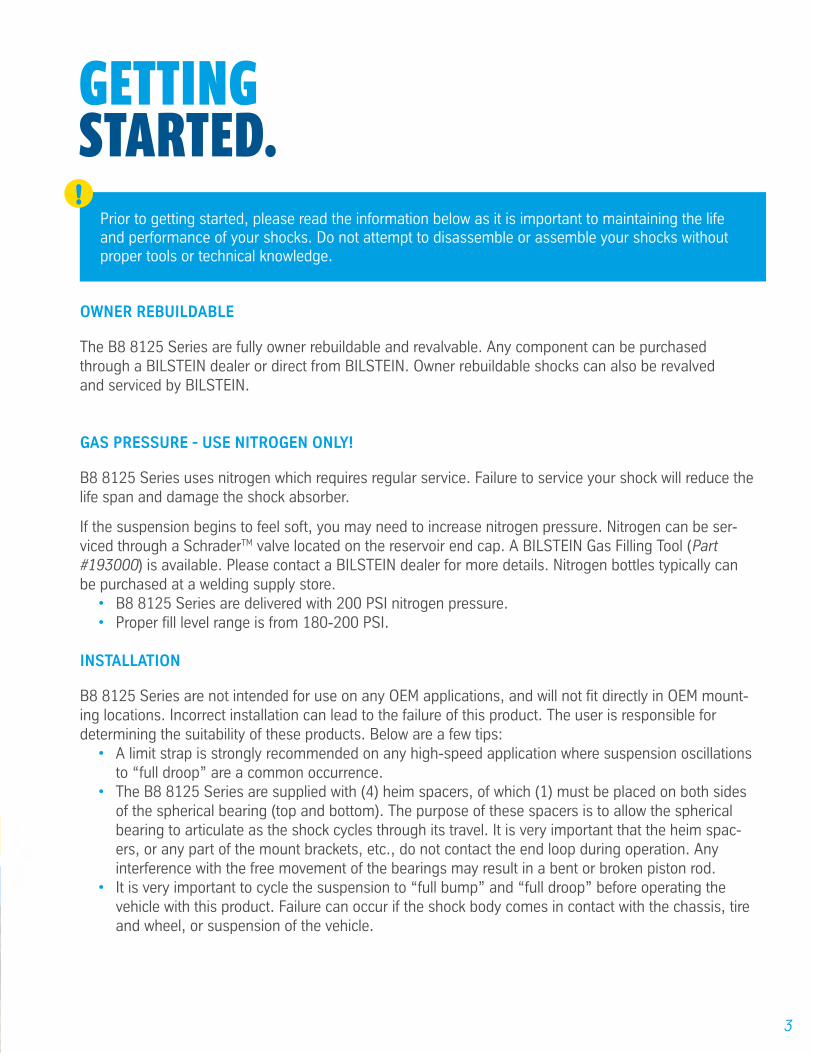
Prior to getting started, please read the information below as it is important to maintaining the life and performance of your shocks. Do not attempt to disassemble or assemble your shocks without proper tools or technical knowledge.
!
4
COILOVER HARDWARE
B8 8125 Series are equipped with dual-rate spring hardware on most models. This consists of a bottom spring hat, a spring slider, (2) spring crossover nuts, and an upper spring seat. The spring seat and the spring crossover nuts are installed in the proper orientation.
SPRING SEATThe upper spring seat is threaded and can be used to adjust spring preload. Rotating the spring seat clockwise will increase preload (lift), while rotating counter clockwise will decrease preload (lower). It’s recommended to only adjust spring preload when the suspension is fully unloaded. This will make the operation much easier. If the spring seat cannot be rotated by hand, use a standard 3/8” center punch, placed in the holes, to improve leverage. Once the spring preload is set you can lock the spring seat into position by tightening the socket head bolt.
SPRING CROSSOVER NUTSPositioned above the spring slider and below the upper spring seat, the crossover nuts are used to adjust the transition moment from the softer combined dual rate spring to the stiffer single rate. These nuts can be rotated clockwise and counter clockwise to adjust for the desired spring transition. Rotating the cross-over nuts against each other will lock them into place.
COILOVER SPRINGSThe B8 8125 Series use industry standard coilover springs. A 46mm(2.0”) diameter shock absorber uses a 2.5” ID coil and a 60mm(2.65”) diameter shock absorber uses a 3” ID coil. It is important that the bottom coil, on the dual rate set up, be at least as long as the shock travel (Example: A 12” travel shock should use a lower spring at a minimum length of 12”). To install the springs, first slide the upper spring into position, install the slider, install the lower spring and then install the lower spring hat. Shorter travel 5”, 6”, and 8” B8 8125 Series will only have a single rate hardware kit. For these models install the single spring and then install the lower spring hat.
ZINC-PLATED FINISH
B8 8125 Series feature a proprietary BILSTEIN zinc plated finish. This finish must be serviced in order to maintain its luster. Particularly in moist climates, a protective coating, such as a wax or lubricating oil should be periodically applied to prevent tarnishing. This finish is not covered under warranty.
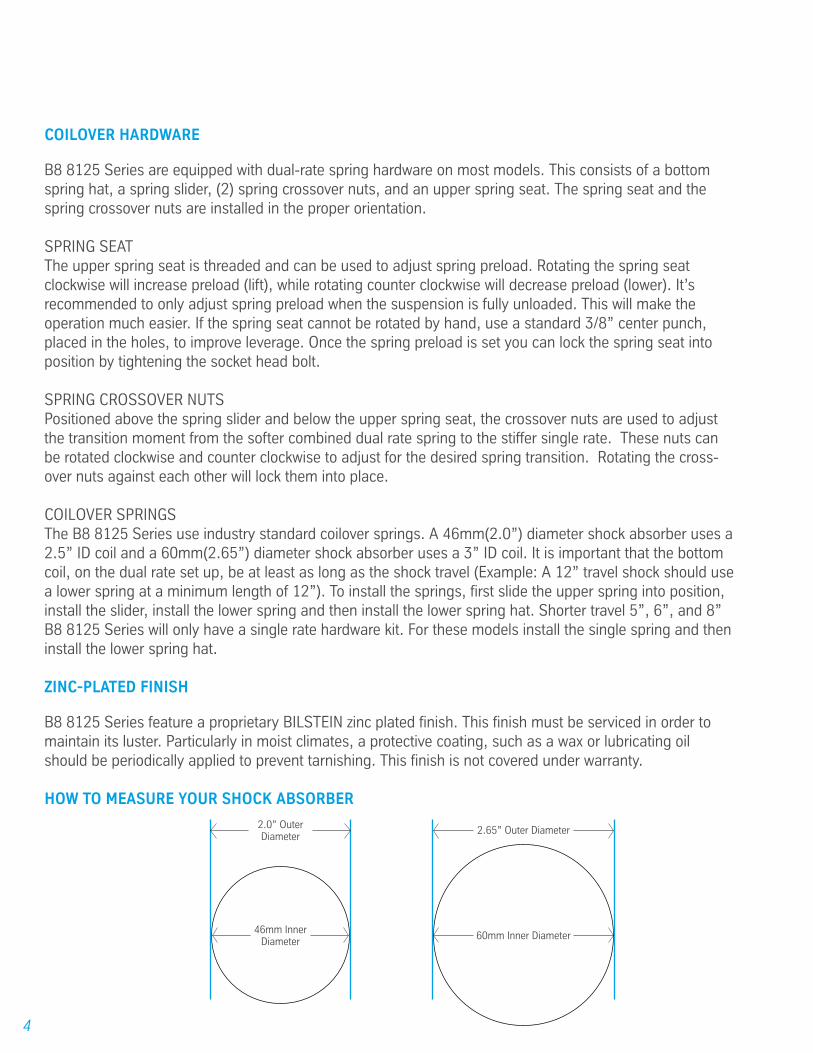
HOW TO MEASURE YOUR SHOCK ABSORBER
2.0” Outer Diameter
46mm Inner Diameter
2.65” Outer Diameter
60mm Inner Diameter

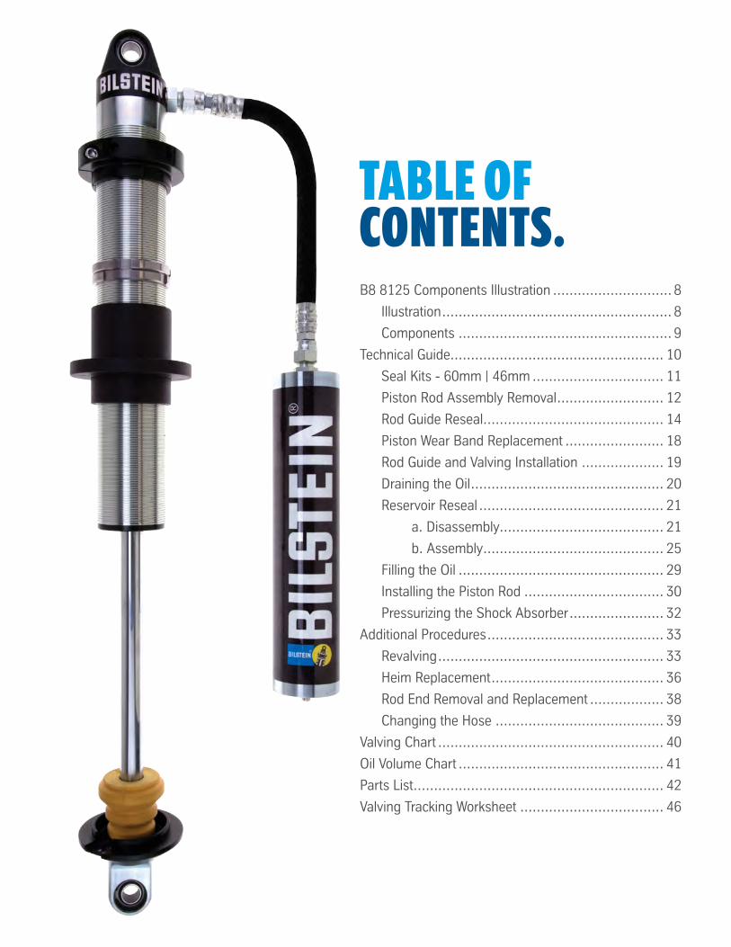
TABLE OFCONTENTS.B8 8125 Components Illustration ............................. 8
Illustration ........................................................ 8
Components .................................................... 9
Technical Guide.................................................... 10
Seal Kits - 60mm | 46mm ................................ 11
Piston Rod Assembly Removal .......................... 12
Rod Guide Reseal ............................................ 14
Piston Wear Band Replacement ........................ 18
Rod Guide and Valving Installation .................... 19
Draining the Oil ............................................... 20
Reservoir Reseal ............................................. 21
a. Disassembly........................................ 21
b. Assembly ............................................ 25
Filling the Oil .................................................. 29
Installing the Piston Rod .................................. 30
Pressurizing the Shock Absorber ....................... 32
Additional Procedures ........................................... 33
Revalving ....................................................... 33
Heim Replacement .......................................... 36
Rod End Removal and Replacement .................. 38
Changing the Hose ......................................... 39
Valving Chart ....................................................... 40
Oil Volume Chart .................................................. 41
Parts List ............................................................. 42
Valving Tracking Worksheet ................................... 46
8
18172
322
21
1
2323
65
7
4
8
9101211
13
24
1416
32
283334
26
3029
283227
19
LOCTITE #271 Threadlocker
161515
16
25 25
2525
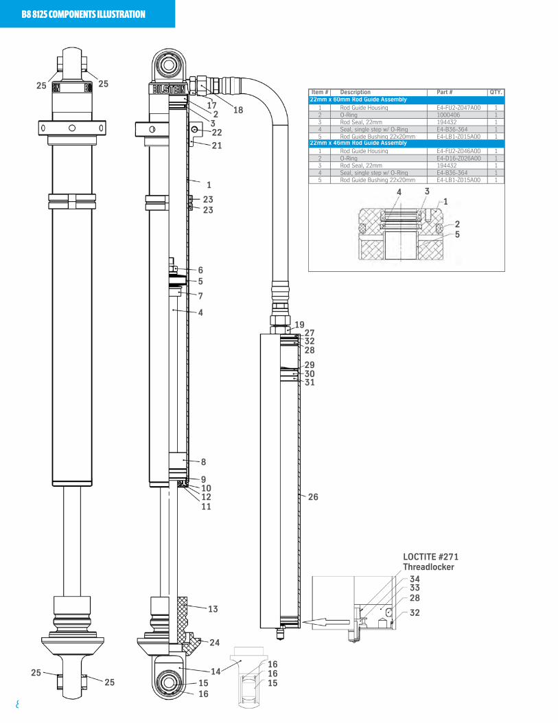
B8 8125 COMPONENTS ILLUSTRATION
4 31
25
Item # Description Part # QTY.
1 Rod Guide Housing E4-FU2-Z047A00 12 O-Ring 1000406 13 Rod Seal, 22mm 194432 14 Seal, single step w/ O-Ring E4-B36-364 15 Rod Guide Bushing 22x20mm E4-LB1-Z015A00 1
1 Rod Guide Housing E4-FU2-Z046A00 12 O-Ring E4-D16-Z026A00 13 Rod Seal, 22mm 194432 14 Seal, single step w/ O-Ring E4-B36-364 15 Rod Guide Bushing 22x20mm E4-LB1-Z015A00 1
22mm x 60mm Rod Guide Assembly
22mm x 46mm Rod Guide Assembly
31
9
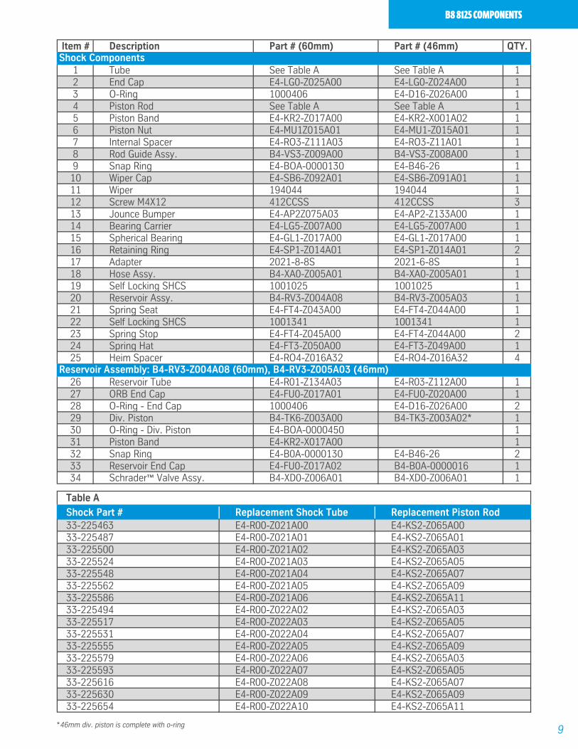
B8 8125 COMPONENTS
Table A
Shock Part # Replacement Shock Tube Replacement Piston Rod33-225463 E4-R00-Z021A00 E4-KS2-Z065A0033-225487 E4-R00-Z021A01 E4-KS2-Z065A0133-225500 E4-R00-Z021A02 E4-KS2-Z065A0333-225524 E4-R00-Z021A03 E4-KS2-Z065A0533-225548 E4-R00-Z021A04 E4-KS2-Z065A0733-225562 E4-R00-Z021A05 E4-KS2-Z065A0933-225586 E4-R00-Z021A06 E4-KS2-Z065A1133-225494 E4-R00-Z022A02 E4-KS2-Z065A0333-225517 E4-R00-Z022A03 E4-KS2-Z065A0533-225531 E4-R00-Z022A04 E4-KS2-Z065A0733-225555 E4-R00-Z022A05 E4-KS2-Z065A0933-225579 E4-R00-Z022A06 E4-KS2-Z065A0333-225593 E4-R00-Z022A07 E4-KS2-Z065A0533-225616 E4-R00-Z022A08 E4-KS2-Z065A0733-225630 E4-R00-Z022A09 E4-KS2-Z065A0933-225654 E4-R00-Z022A10 E4-KS2-Z065A11
Item # Description Part # (60mm) Part # (46mm) QTY.
1 Tube See Table A See Table A 12 End Cap E4-LG0-Z025A00 E4-LG0-Z024A00 13 O-Ring 1000406 E4-D16-Z026A00 14 Piston Rod See Table A See Table A 15 Piston Band E4-KR2-Z017A00 E4-KR2-X001A02 16 Piston Nut E4-MU1Z015A01 E4-MU1-Z015A01 17 Internal Spacer E4-RO3-Z111A03 E4-RO3-Z11A01 18 Rod Guide Assy. B4-VS3-Z009A00 B4-VS3-Z008A00 19 Snap Ring E4-BOA-0000130 E4-B46-26 1
10 Wiper Cap E4-SB6-Z092A01 E4-SB6-Z091A01 111 Wiper 194044 194044 112 Screw M4X12 412CCSS 412CCSS 313 Jounce Bumper E4-AP2Z075A03 E4-AP2-Z133A00 114 Bearing Carrier E4-LG5-Z007A00 E4-LG5-Z007A00 115 Spherical Bearing E4-GL1-Z017A00 E4-GL1-Z017A00 116 Retaining Ring E4-SP1-Z014A01 E4-SP1-Z014A01 217 Adapter 2021-8-8S 2021-6-8S 118 Hose Assy. B4-XA0-Z005A01 B4-XA0-Z005A01 119 Self Locking SHCS 1001025 1001025 120 Reservoir Assy. B4-RV3-Z004A08 B4-RV3-Z005A03 121 Spring Seat E4-FT4-Z043A00 E4-FT4-Z044A00 122 Self Locking SHCS 1001341 1001341 123 Spring Stop E4-FT4-Z045A00 E4-FT4-Z044A00 224 Spring Hat E4-FT3-Z050A00 E4-FT3-Z049A00 125 Heim Spacer E4-RO4-Z016A32 E4-RO4-Z016A32 4
26 Reservoir Tube E4-R01-Z134A03 E4-R03-Z112A00 127 ORB End Cap E4-FU0-Z017A01 E4-FU0-Z020A00 128 O-Ring - End Cap 1000406 E4-D16-Z026A00 229 Div. Piston B4-TK6-Z003A00 B4-TK3-Z003A02* 130 O-Ring - Div. Piston E4-BOA-0000450 131 Piston Band E4-KR2-X017A00 132 Snap Ring E4-B0A-0000130 E4-B46-26 233 Reservoir End Cap E4-FU0-Z017A02 B4-B0A-0000016 134 Schrader™ Valve Assy. B4-XD0-Z006A01 B4-XD0-Z006A01 1
Reservoir Assembly: B4-RV3-Z004A08 (60mm), B4-RV3-Z005A03 (46mm)
Shock Components
*46mm div. piston is complete with o-ring
10
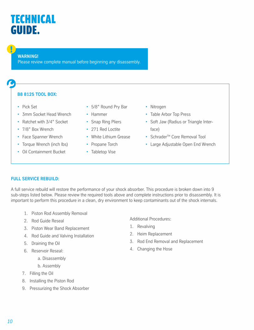
TECHNICALGUIDE.
FULL SERVICE REBUILD:
A full service rebuild will restore the performance of your shock absorber. This procedure is broken down into 9 sub-steps listed below. Please review the required tools above and complete instructions prior to disassembly. It is important to perform this procedure in a clean, dry environment to keep contaminants out of the shock internals.
1. Piston Rod Assembly Removal
2. Rod Guide Reseal
3. Piston Wear Band Replacement
4. Rod Guide and Valving Installation
5. Draining the Oil
6. Reservoir Reseal:
a. Disassembly
b. Assembly
7. Filling the Oil
8. Installing the Piston Rod
9. Pressurizing the Shock Absorber
Additional Procedures:
1. Revalving
2. Heim Replacement
3. Rod End Removal and Replacement
4. Changing the Hose
B8 8125 TOOL BOX:
• Nitrogen
• Table Arbor Top Press
• Soft Jaw (Radius or Triangle Inter-
face)
• SchraderTM Core Removal Tool
• Large Adjustable Open End Wrench
• 5/8” Round Pry Bar
• Hammer
• Snap Ring Pliers
• 271 Red Loctite
• White Lithium Grease
• Propane Torch
• Tabletop Vise
• Pick Set
• 3mm Socket Head Wrench
• Ratchet with 3/4” Socket
• 7/8” Box Wrench
• Face Spanner Wrench
• Torque Wrench (inch lbs)
• Oil Containment Bucket
WARNING! Please review complete manual before beginning any disassembly.
!
11
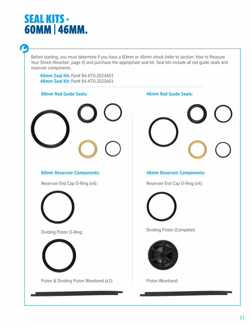
SEAL KITS - 60MM | 46MM.
Before starting, you must determine if you have a 60mm or 46mm shock (refer to section: How to Measure Your Shock Absorber, page 4) and purchase the appropriate seal kit. Seal kits include all rod guide seals and reservoir components.
60mm Seal Kit: Part# B4-KT0-Z024A0146mm Seal Kit: Part# B4-KT0-Z023A01
60mm Reservoir Components:
60mm Rod Guide Seals:
Reservoir End Cap O-Ring (x4): Reservoir End Cap O-Ring (x4):
Dividing Piston (Complete):Dividing Piston O-Ring:
Piston & Dividing Piston Wearband (x2):
46mm Reservoir Components:
46mm Rod Guide Seals:
Piston Wearband:

12
PISTON ROD ASSEMBLYREMOVAL .STEP 1
Place shock upside down in vise and clamp on eyelet.
STEP 2
Using pick, release all gas pressure and remove SchraderTM core.
Use a buffering layer between the clamp and eyelet, such as a towel, to avoid scratching the anodized end cap.
STEP 3
Using a 3mm socket head wrench, remove the 3 socket head screws from the rod guide.
STEP 4
Slide black wiper cap up the piston rod, revealing the rod guide below.
IMPORTANT! Do not collapse the piston rod once the gas pressure is extinguished.
!
13
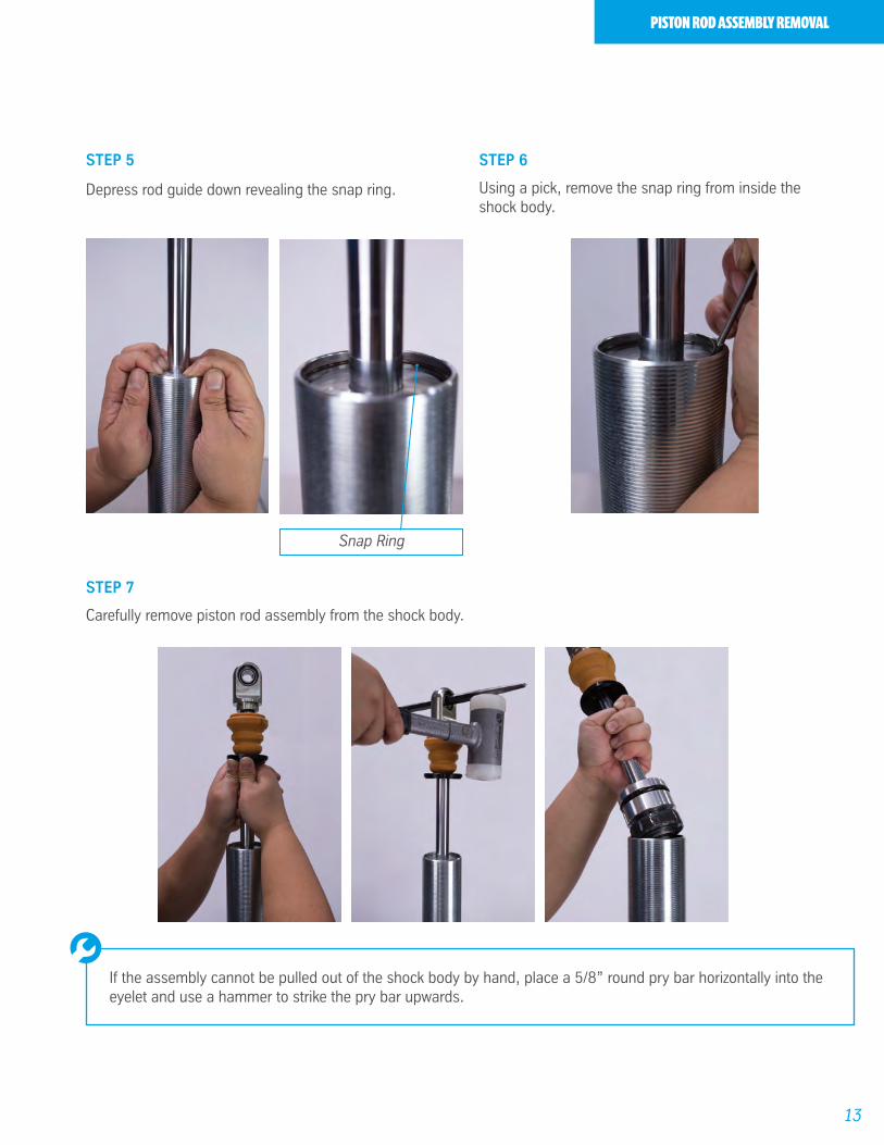
PISTON ROD ASSEMBLY REMOVAL
STEP 6
Using a pick, remove the snap ring from inside the shock body.
STEP 5
Depress rod guide down revealing the snap ring.
STEP 7
Carefully remove piston rod assembly from the shock body.
If the assembly cannot be pulled out of the shock body by hand, place a 5/8” round pry bar horizontally into the eyelet and use a hammer to strike the pry bar upwards.
Snap Ring
14
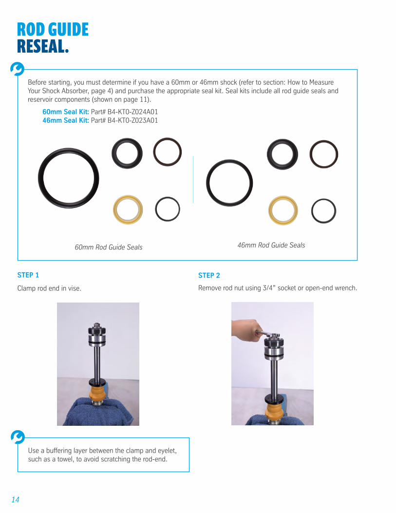
ROD GUIDERESEAL .
STEP 1
Clamp rod end in vise.
STEP 2
Remove rod nut using 3/4” socket or open-end wrench.
Use a buffering layer between the clamp and eyelet, such as a towel, to avoid scratching the rod-end.
Before starting, you must determine if you have a 60mm or 46mm shock (refer to section: How to Measure Your Shock Absorber, page 4) and purchase the appropriate seal kit. Seal kits include all rod guide seals and reservoir components (shown on page 11).
60mm Seal Kit: Part# B4-KT0-Z024A0146mm Seal Kit: Part# B4-KT0-Z023A01
60mm Rod Guide Seals 46mm Rod Guide Seals

15
ROD GUIDE RESEAL
STEP 4
Remove rod guide from piston rod.
STEP 6
Using a pick, remove all five seals from the rod guide and wiper cap.
STEP 5
Remove wiper cap from piston rod.
STEP 3
Remove valving discs and piston from rod.
IMPORTANT! To maintain performance, it is imperative that the valve discs and components are removed and re-placed in the precise order that they were removed. We suggest laying out the compression valve stack, piston, and rebound valve stack in order.
!
16
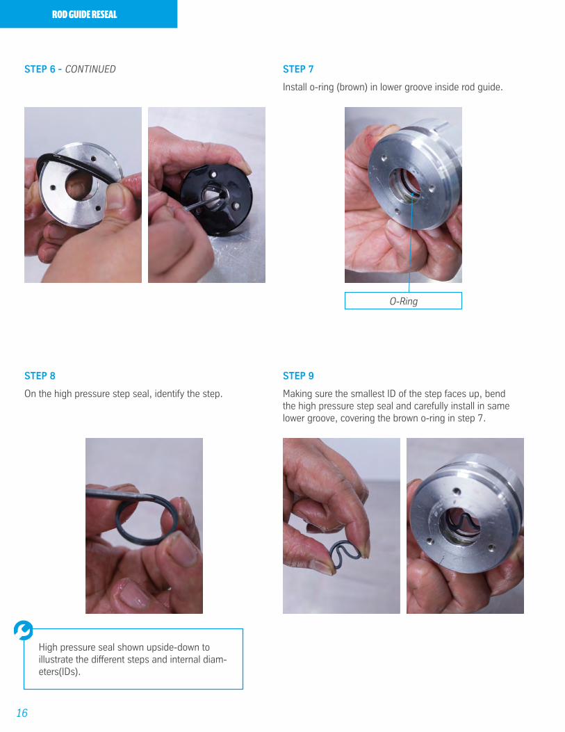
ROD GUIDE RESEAL
STEP 7
Install o-ring (brown) in lower groove inside rod guide.
STEP 9
Making sure the smallest ID of the step faces up, bend the high pressure step seal and carefully install in same lower groove, covering the brown o-ring in step 7.
STEP 8
On the high pressure step seal, identify the step.
STEP 6 - CONTINUED
High pressure seal shown upside-down to illustrate the different steps and internal diam-eters(IDs).
O-Ring
17
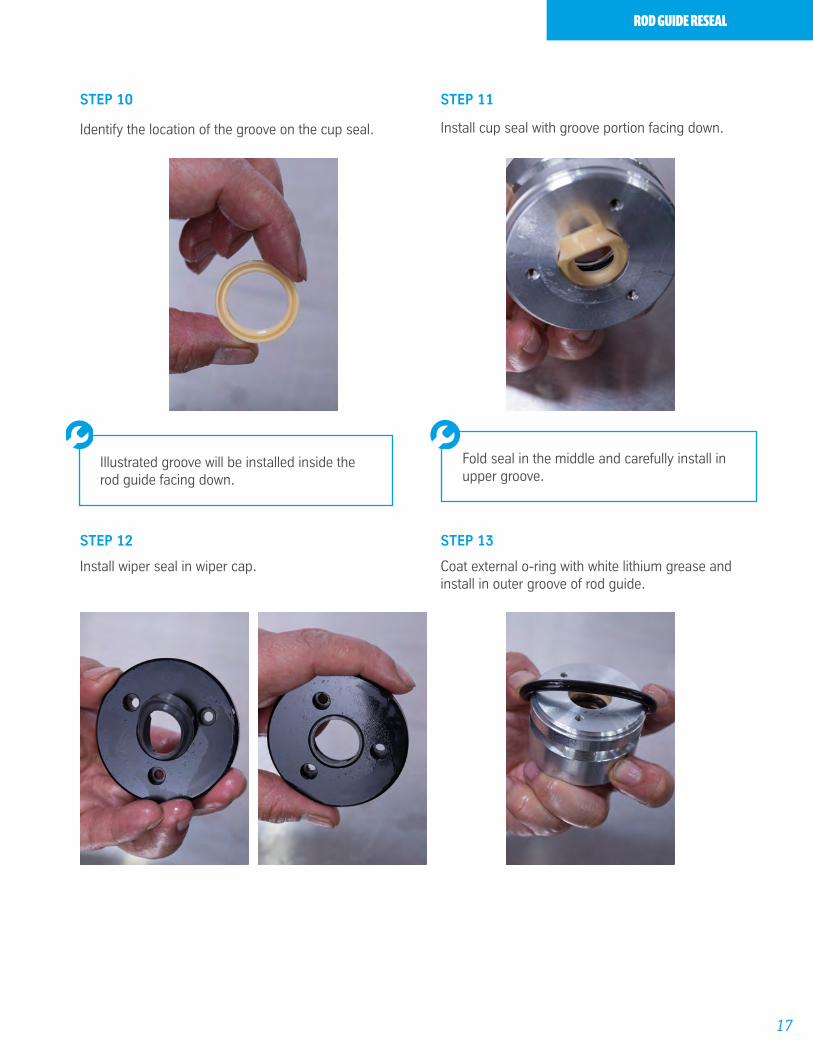
ROD GUIDE RESEAL
STEP 11
Install cup seal with groove portion facing down.
STEP 12
Install wiper seal in wiper cap.
STEP 13
Coat external o-ring with white lithium grease and install in outer groove of rod guide.
STEP 10
Identify the location of the groove on the cup seal.
Illustrated groove will be installed inside the rod guide facing down.
Fold seal in the middle and carefully install in upper groove.
18
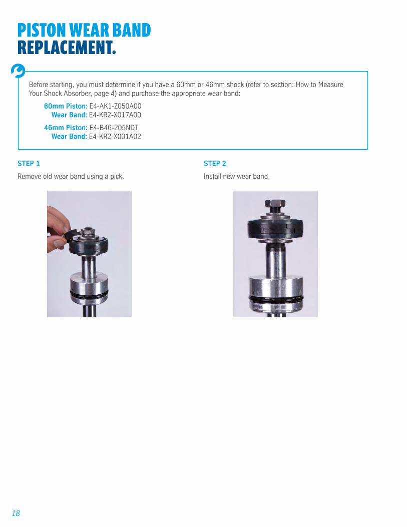
PISTON WEAR BANDREPLACEMENT.
STEP 1
Remove old wear band using a pick.
STEP 2
Install new wear band.
Before starting, you must determine if you have a 60mm or 46mm shock (refer to section: How to Measure Your Shock Absorber, page 4) and purchase the appropriate wear band:
60mm Piston: E4-AK1-Z050A00Wear Band: E4-KR2-X017A00
46mm Piston: E4-B46-205NDTWear Band: E4-KR2-X001A02
19
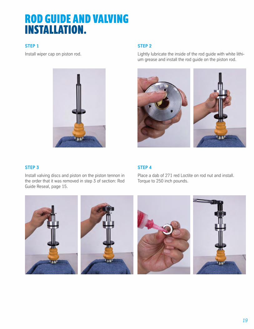
ROD GUIDE AND VALVING INSTALLATION.STEP 1
Install wiper cap on piston rod.
STEP 2
Lightly lubricate the inside of the rod guide with white lithi-um grease and install the rod guide on the piston rod.
STEP 4
Place a dab of 271 red Loctite on rod nut and install. Torque to 250 inch pounds.
STEP 3
Install valving discs and piston on the piston tennon in the order that it was removed in step 3 of section: Rod Guide Reseal, page 15.
20
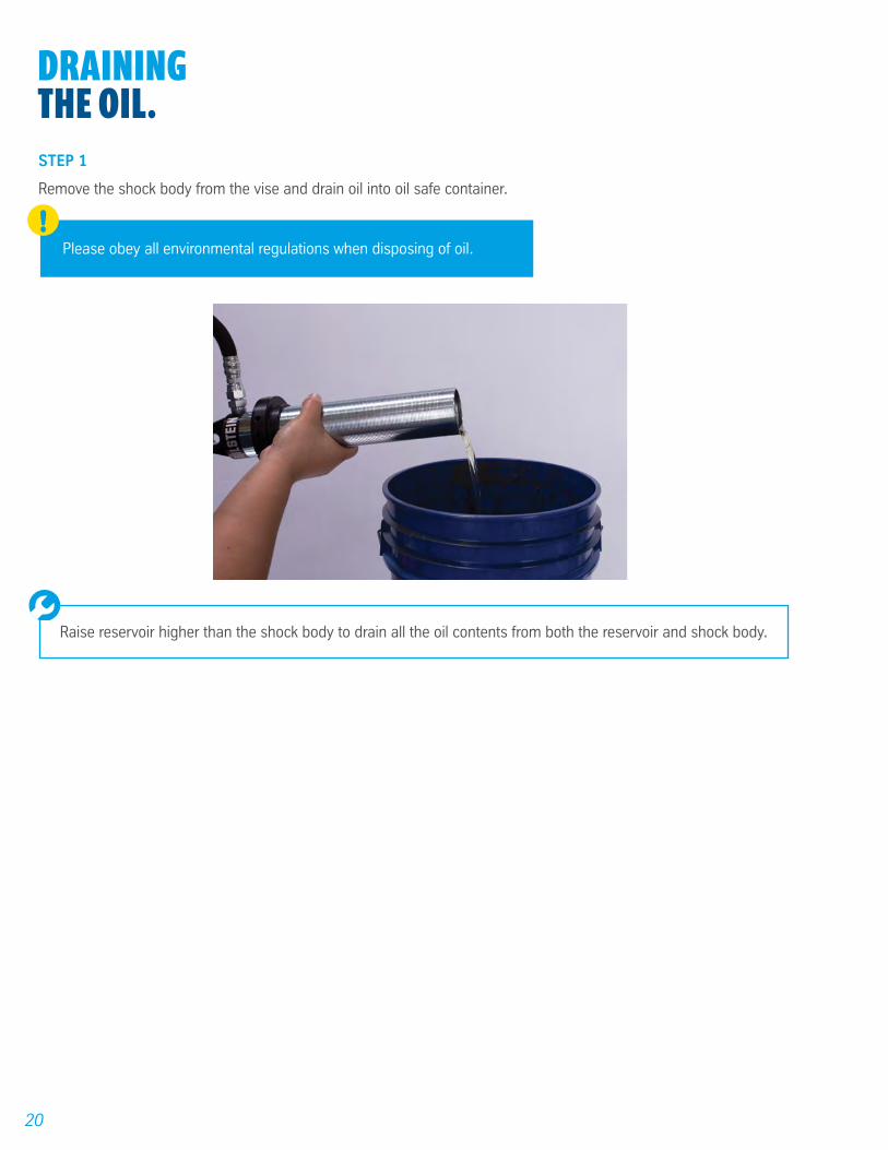
DRAININGTHE OIL .STEP 1
Remove the shock body from the vise and drain oil into oil safe container.
Raise reservoir higher than the shock body to drain all the oil contents from both the reservoir and shock body.
Please obey all environmental regulations when disposing of oil. !
21
RESERVOIR RESEAL -DISASSEMBLY.
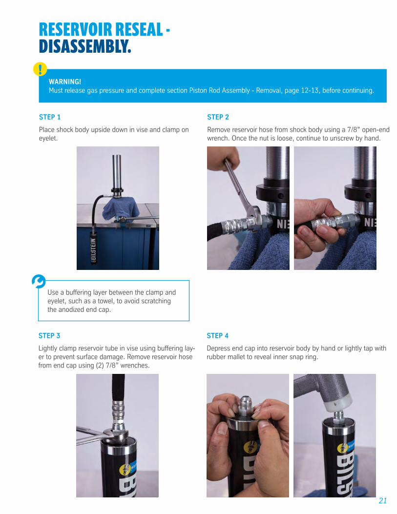
STEP 1
Place shock body upside down in vise and clamp on eyelet.
STEP 2
Remove reservoir hose from shock body using a 7/8” open-end wrench. Once the nut is loose, continue to unscrew by hand.
Use a buffering layer between the clamp and eyelet, such as a towel, to avoid scratching the anodized end cap.
WARNING!Must release gas pressure and complete section Piston Rod Assembly - Removal, page 12-13, before continuing.
!
STEP 3
Lightly clamp reservoir tube in vise using buffering lay-er to prevent surface damage. Remove reservoir hose from end cap using (2) 7/8” wrenches.
STEP 4
Depress end cap into reservoir body by hand or lightly tap with rubber mallet to reveal inner snap ring.
22
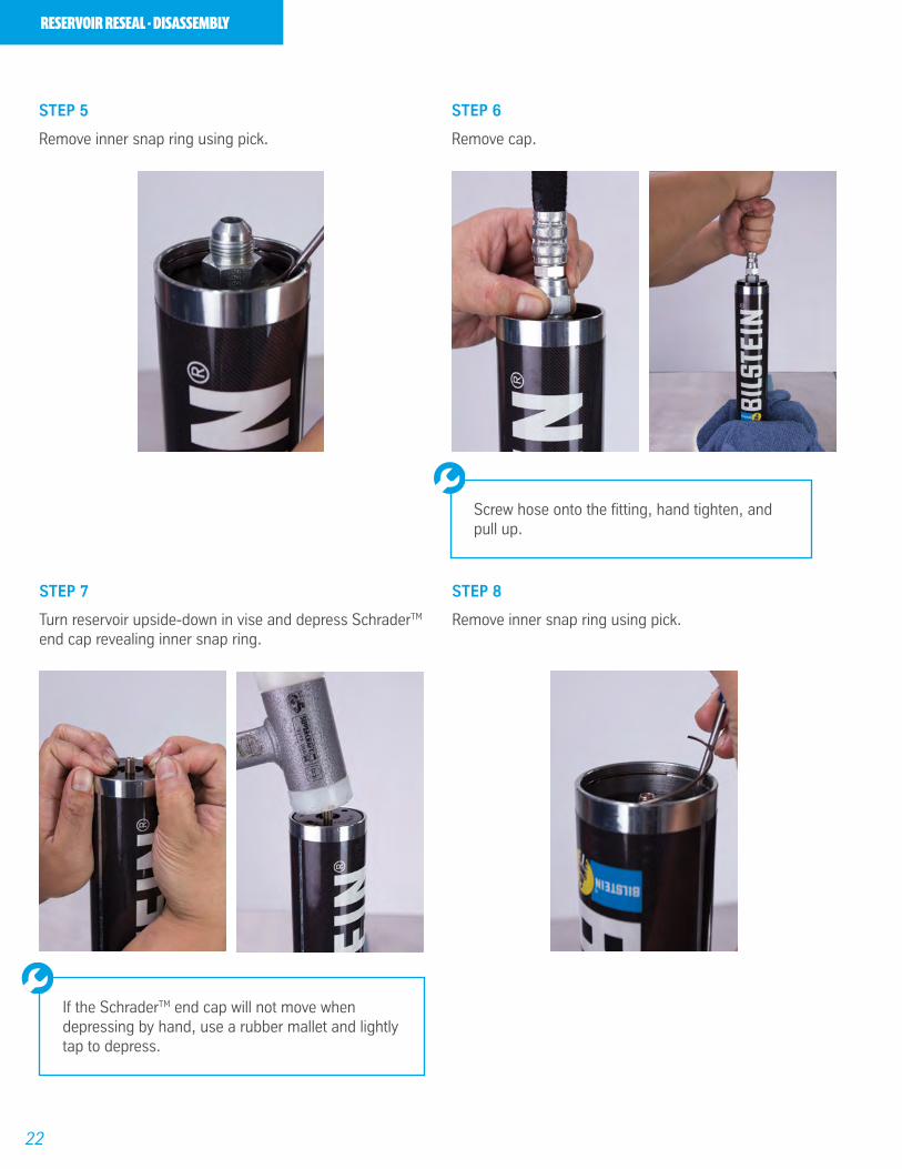
RESERVOIR RESEAL - DISASSEMBLY
STEP 5
Remove inner snap ring using pick.
STEP 6
Remove cap.
Screw hose onto the fitting, hand tighten, and pull up.
STEP 7
Turn reservoir upside-down in vise and depress SchraderTM end cap revealing inner snap ring.
STEP 8
Remove inner snap ring using pick.
If the SchraderTM end cap will not move when depressing by hand, use a rubber mallet and lightly tap to depress.
23
RESERVOIR RESEAL - DISASSEMBLY
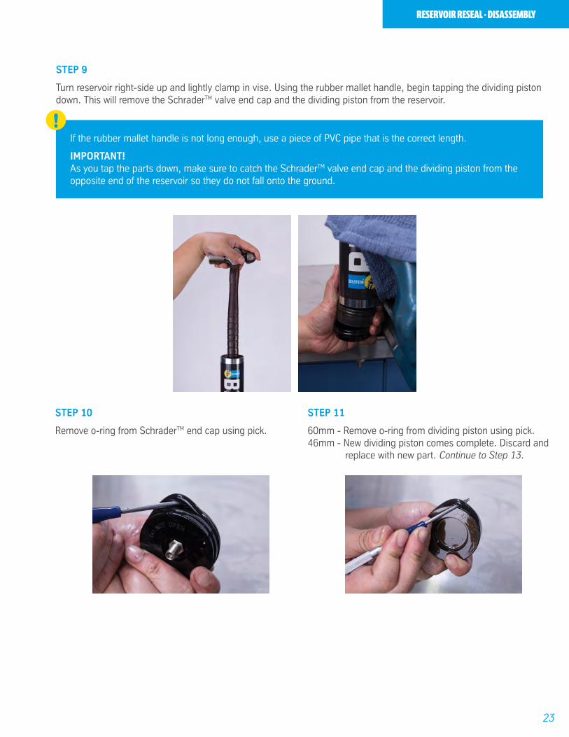
STEP 9
Turn reservoir right-side up and lightly clamp in vise. Using the rubber mallet handle, begin tapping the dividing piston down. This will remove the SchraderTM valve end cap and the dividing piston from the reservoir.
If the rubber mallet handle is not long enough, use a piece of PVC pipe that is the correct length.
IMPORTANT! As you tap the parts down, make sure to catch the SchraderTM valve end cap and the dividing piston from the opposite end of the reservoir so they do not fall onto the ground.
!
STEP 10
Remove o-ring from SchraderTM end cap using pick.
STEP 11
60mm - Remove o-ring from dividing piston using pick.46mm - New dividing piston comes complete. Discard and
replace with new part. Continue to Step 13.

24
STEP 12
Remove wear band from dividing piston.
STEP 13
Remove o-ring from reservoir end cap using pick.
RESERVOIR RESEAL - DISASSEMBLY

25
RESERVOIR RESEAL -ASSEMBLY.
STEP 1
46mm & 60mm - Install new o-ring on SchraderTM end cap. Use white lithium grease on o-ring to aid in installation.
STEP 2
46mm & 60mm - Install new o-ring, on reservoir end cap. Use white lithium grease on o-ring to aid in installation. Continue on to step 3 (60mm) or step 5 (46mm).
Piston & Dividing Piston Wearband (x2): Piston Wearband:
Before starting, you must determine if you have a 60mm or 46mm shock (refer to section: How to Measure Your Shock Absorber, page 4) and purchase the necessary components. All seals and components are includ-ed in the seal kits shown on page 11, or can be purchased separately using part numbers below.
60mm Seals:
Reservoir End Cap O-Ring (x4): Reservoir End Cap O-Ring (x4):
Dividing Piston (Complete):Dividing Piston O-Ring:
46mm Seals:
26
RESERVOIR RESEAL - ASSEMBLY
STEP 3
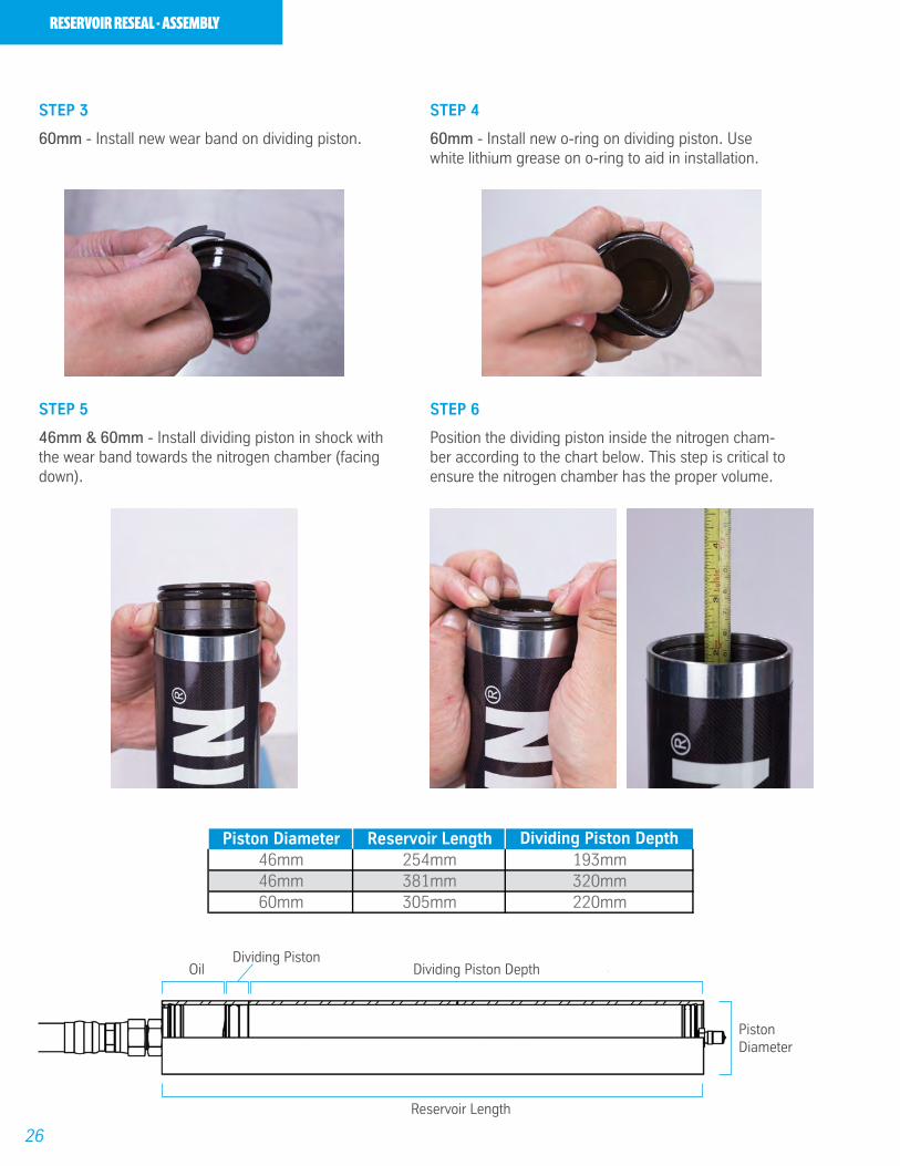
60mm - Install new wear band on dividing piston.
STEP 5
46mm & 60mm - Install dividing piston in shock with the wear band towards the nitrogen chamber (facing down).
STEP 4
60mm - Install new o-ring on dividing piston. Use white lithium grease on o-ring to aid in installation.
STEP 6
Position the dividing piston inside the nitrogen cham-ber according to the chart below. This step is critical to ensure the nitrogen chamber has the proper volume.
Piston Diameter Reservoir Length Dividing Piston Depth46mm 254mm 193mm46mm 381mm 320mm60mm 305mm 220mm
OilDividing Piston
Dividing Piston Depth
PistonDiameter
Reservoir Length

27
RESERVOIR RESEAL - ASSEMBLY
STEP 7
Install reservoir end cap in reservoir tube and depress downwards so it is right below the inner snap ring groove.
STEP 8
Install inner snap ring and confirm it is seated properly inside snap ring groove.
STEP 9
Install hose on reservoir end cap and hand tighten.
STEP 10
Grasping the hose, pull end cap towards snap ring. Inspect assembly to assure the snap ring is properly seated.

28
RESERVOIR RESEAL - ASSEMBLY
STEP 11
Tighten hose using two 7/8” box wrenches.
STEP 12
Flip the reservoir upside-down in vise and install SchraderTM end cap so that it is positioned right below the inner snap ring.
IMPORTANT!Make sure the SchraderTM core is removed.
!
STEP 13
Install inner snap ring and confirm it is seated properly inside snap ring groove.
29
FILLINGTHE OIL .STEP 1
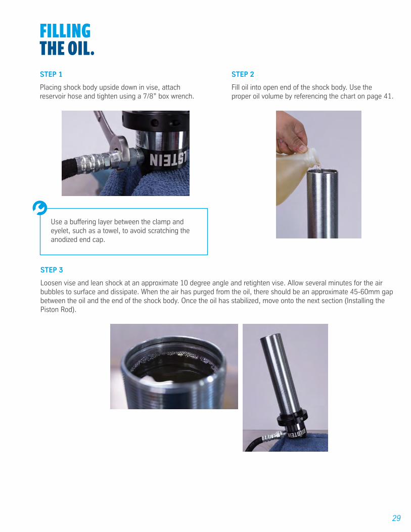
Placing shock body upside down in vise, attach reservoir hose and tighten using a 7/8” box wrench.
STEP 2
Fill oil into open end of the shock body. Use the proper oil volume by referencing the chart on page 41.
STEP 3
Loosen vise and lean shock at an approximate 10 degree angle and retighten vise. Allow several minutes for the air bubbles to surface and dissipate. When the air has purged from the oil, there should be an approximate 45-60mm gap between the oil and the end of the shock body. Once the oil has stabilized, move onto the next section (Installing the Piston Rod).
Use a buffering layer between the clamp and eyelet, such as a towel, to avoid scratching the anodized end cap.
30
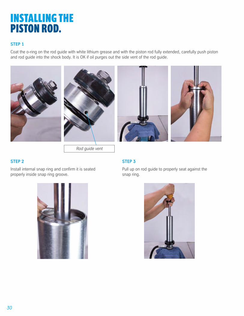
INSTALLING THEPISTON ROD.STEP 1
Coat the o-ring on the rod guide with white lithium grease and with the piston rod fully extended, carefully push piston and rod guide into the shock body. It is OK if oil purges out the side vent of the rod guide.
STEP 2
Install internal snap ring and confirm it is seated properly inside snap ring groove.
STEP 3
Pull up on rod guide to properly seat against the snap ring.
Rod guide vent
31
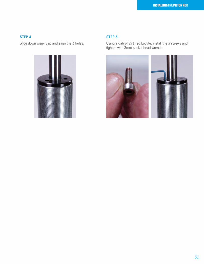
INSTALLING THE PISTON ROD
STEP 4
Slide down wiper cap and align the 3 holes.
STEP 5
Using a dab of 271 red Loctite, install the 3 screws and tighten with 3mm socket head wrench.

32
PRESSURIZING THESHOCK ABSORBER.STEP 1
Install SchraderTM Core.
STEP 2
Pressurize with nitrogen to desired level.
IMPORTANT!B8 8125 Series are delivered with 200 PSI nitrogen pressure. Proper fill level range is from 180-200 PSI.
!
33
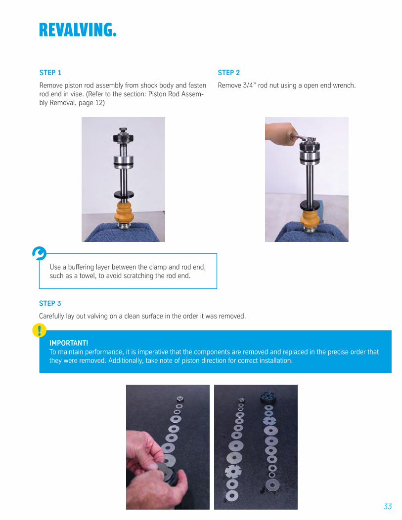
REVALVING.
STEP 3
Carefully lay out valving on a clean surface in the order it was removed.
STEP 1
Remove piston rod assembly from shock body and fasten rod end in vise. (Refer to the section: Piston Rod Assem-bly Removal, page 12)
STEP 2
Remove 3/4” rod nut using a open end wrench.
Use a buffering layer between the clamp and rod end, such as a towel, to avoid scratching the rod end.
IMPORTANT! To maintain performance, it is imperative that the components are removed and replaced in the precise order that they were removed. Additionally, take note of piston direction for correct installation.
!
34
REVALVING
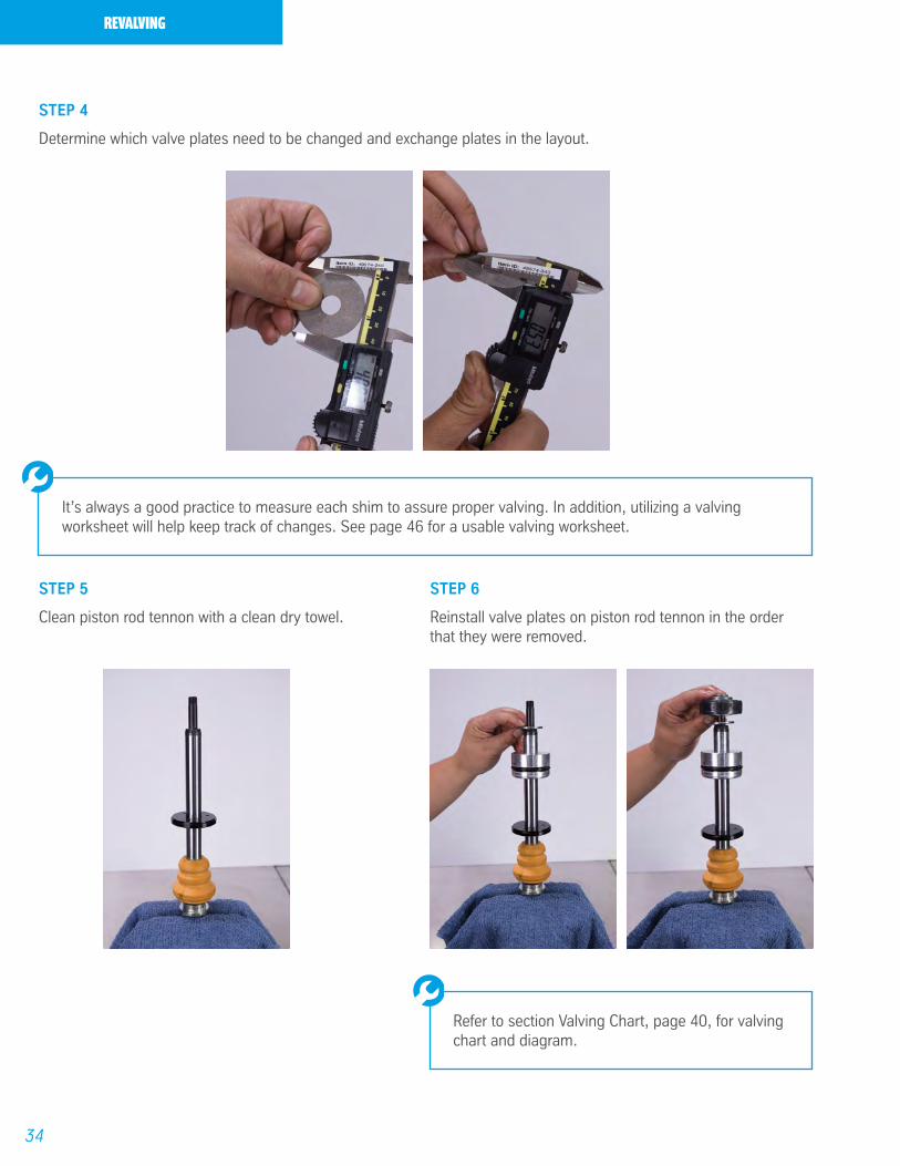
STEP 6
Reinstall valve plates on piston rod tennon in the order that they were removed.
STEP 5
Clean piston rod tennon with a clean dry towel.
STEP 4
Determine which valve plates need to be changed and exchange plates in the layout.
It’s always a good practice to measure each shim to assure proper valving. In addition, utilizing a valving worksheet will help keep track of changes. See page 46 for a usable valving worksheet.
Refer to section Valving Chart, page 40, for valving chart and diagram.

35
STEP 8
Install piston rod nut and torque to 250 inch pounds.
REVALVING
STEP 9
Carefully reassemble piston rod assembly in shock body.
STEP 7
Place a dab of 271 red Loctite on piston rod nut.
36
HEIMREPLACEMENT.STEP 1
Using snap ring pliers, remove snap ring from both sides on the rod end.
STEP 2
Using table press, remove heim joint.
STEP 3
Reinstall snap ring on one side of the rod end.
STEP 4
Install new heim in eyelet.
Two sockets may be used on either side of the rod end to remove heim joint using a table press. The lower socket must be large enough for the heim to drop into.
37
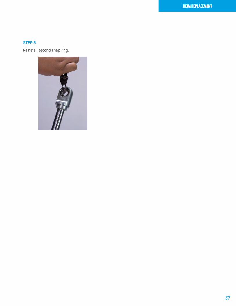
HEIM REPLACEMENT
STEP 5
Reinstall second snap ring.
38
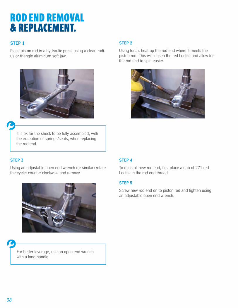
ROD END REMOVAL& REPLACEMENT.STEP 1
Place piston rod in a hydraulic press using a clean radi-us or triangle aluminum soft jaw.
STEP 2
Using torch, heat up the rod end where it meets the piston rod. This will loosen the red Loctite and allow for the rod end to spin easier.
It is ok for the shock to be fully assembled, with the exception of springs/seats, when replacing the rod end.
STEP 3
Using an adjustable open end wrench (or similar) rotate the eyelet counter clockwise and remove.
STEP 5
Screw new rod end on to piston rod and tighten using an adjustable open end wrench.
STEP 4
To reinstall new rod end, first place a dab of 271 red Loctite in the rod end thread.
For better leverage, use an open end wrench with a long handle.

39
CHANGINGTHE HOSE.
STEP 1
Remove piston rod assembly from shock body. (Refer to the section: Piston Rod Assembly Removal, page 12)
STEP 2
Drain shock oil.(Refer to the section: Draining the Oil, page 20)
STEP 5
Replace new hose on reservoir.
STEP 6
Fill shock with oil. (Refer to the section: Filling the Oil, page 29)
STEP 7
Install piston rod into shock body (Refer to the section: Installing the Piston Rod, page 30)
STEP 8
Charge shock with desired nitrogen pressure.(Refer to the section: Pressurizing the Shock Absorber, page 32)
STEP 3
Remove reservoir hose from shock body using 7/8” box wrench.
STEP 4
Remove hose from reservoir end cap using (2) 7/8” box wrenches.
WARNING!Release gas pressure and complete section Piston Rod Assembly - Removal, page 12-13, before continuing.
!

40
VALVINGCHART.
Rebound / Compression 370/110 308/82 275/78 255/70 170/60 Brake 32.5 x 2.5 32.5 x 2.5 32.5 x 2.5 32.5 x 2.5 32.5 x 2.5 Support#4 30x.50 28x.50 28x.50 28x.50 28x.50Support#3 32x.50 32x.50 32x.35 32x.35 32x.30Support#2 36x.50 36x.40 36x.35 36x.35 36x.30Support#1 46.8x.35 42x.40 42x.35 42x.35 42x.30Cover Disc 46.8x.35 46.8x.40 46.8x.40 46.8x.35 46.8x.30Bypass A06 Bleed A06 Bleed A06 Bleed A01 Bleed A11 BleedPreload 32x.35 32x.35 32x.35 32x.35 32x.35Preload 32x.40 32x.40 32x.40 32x.40 32x.40
Piston60mm Digressive
60mm Digressive
60mm Digressive
60mm Digressive
60mm Digressive
Preload 32x.40 32x.40 32x.40 32x.40 32x.40Preload 32x.35 32x.35 32x.35 32x.35 32x.35Bypass A04 Bleed A04 Bleed A04 Bleed A07 Bleed A07 Bleed Cover Disc 46.8x.35 46.8x.35 46.8x.30 46.8x.30 46.8x.30Support#1 42x.35 42x.30 42x30 42x30 42x.30Support#2 36x.35 36x.30 36x.30 36x.30 36x.25Support#3 30x.35 28x.30 28x.30 28x.30 28x.25Support#4 24x.35 22x.30 22x.30 22x.30 22x.25Support#5 18x.50 17x.50 16x.50 15x.50 15x.50Support#6 17x.50 16x.50 15x.50 15x.50Brake 37.5x3 37.5x3 37.5x3 37.5x3 37.5x3
Rebound
Compression
60mm Valve Stacks
Rebound / Compression 360/80 275/78 255/100 180/75 170/60 150/50Brake 20X3.0 20X3.0 20X3.0 20X3.0 20X3.0 20x3.0Support#4 19X50 18X50 19x50 20X50 20X50 20X50Support#3 22X40 22X50 22X50 22X25 22X35 22X30Support#2 28X40 28X40 28X40 28X25 28x40 28x30Support#1 32X40 32X35 32X30 32X25 32X25 32X25Cover Disc 37.4X40 37.4X35 37.4X35 37.4X25 37.4X25 37.4X25Bypass 18X10 18X10 18X10 18x15 18x20 18x10 Piston U37T PISTON U37T PISTON U37T PISTON U37T PISTON U37T PISTON U37T PISTONBypass 18X15 18X15 18X10 18X20 18X20 18X10Cover Disc 37.4X30 37.4X30 37.4X35 37.4X30 37.4X25 35.8x25Support#1 32X30 32X25 32X30 32X30 32X20 32X20Support#2 28X30 28X20 28X30 28X30 28X25 28X25Support#3 22X50 22X50 22X30 22X50 22X35 22X35Support#4 17X50 17X50 19x50 19X50 18x50 18x50Support#5 17X50 17X50 19x50 19X50 18x50 18x50Brake B46-22 B46-22 B46-22 B46-22 B46-22 B46-22
Rebound
Compression
46mm Valve Stacks
Piston Rod
Piston
Nut
Compression Valve Stack Rebound Valve Stack

41
OIL VOLUMECHART.
Part # Description Oil Volume (mL (CC))
33-225463 46mm Coilover W/ Reservoir, 5" Stroke 37433-225487 46mm Coilover W/ Reservoir, 6" Stroke 41733-225500 46mm Coilover W/ Reservoir, 8" Stroke 50133-225524 46mm Coilover W/ Reservoir, 10" Stroke 58633-225548 46mm Coilover W/ Reservoir, 12" Stroke 68433-225562 46mm Coilover W/ Reservoir, 14" Stroke 76833-225586 46mm Coilover W/ Reservoir, 16" Stroke 852
33-225456 60mm Coilover W/ Reservoir, 5" Short Body 62833-225470 60mm Coilover W/ Reservoir, 6" Short Body 70033-225494 60mm Coilover W/ Reservoir, 8" Short Body 84333-225517 60mm Coilover W/ Reservoir, 10" Short Body 102333-225531 60mm Coilover W/ Reservoir, 12" Short Body 115933-225555 60mm Coilover W/ Reservoir, 14" Short Body 133933-225593 60mm Coilover W/ Reservoir, 10" Standard Body 107633-225616 60mm Coilover W/ Reservoir, 12" Standard Body 121233-225630 60mm Coilover W/ Reservoir, 14" Standard Body 142733-225654 60mm Coilover W/ Reservoir, 16" Standard Body 1571
B8 8125 - 46mm (2.0") Oil Volumes
B8 8125 - 60mm (2.65") Oil Volumes

42
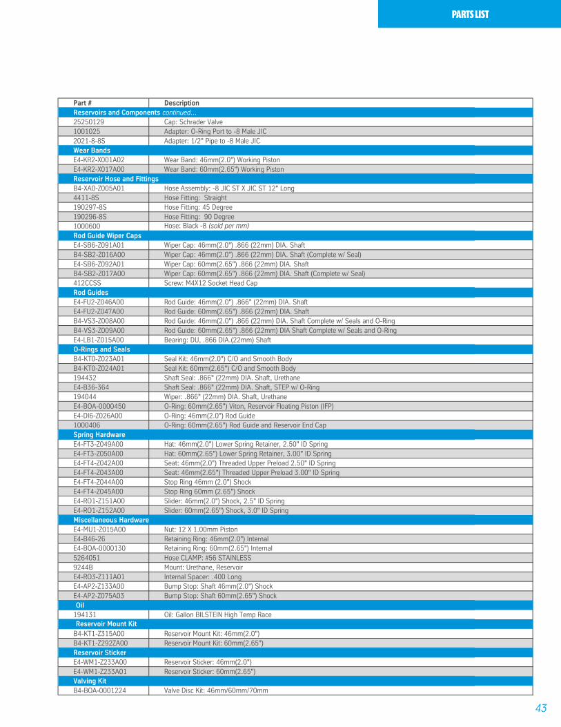
PARTSLIST.
Part # Description
E4-RO0-Z021A00 Body: 46mm(2.0") Coilover, 8.35" Long, 5" TravelE4-RO0-Z021A01 Body: 46mm(2.0") Coilover, 9.35" Long, 6" TravelE4-RO0-Z021A02 Body: 46mm(2.0") Coilover, 11.35" Long, 8" TravelE4-RO0-Z021A03 Body: 46mm(2.0") Coilover, 13.35" Long, 10" TravelE4-RO0-Z021A04 Body: 46mm(2.0") Coilover, 15.85" Long, 12" Travel E4-RO0-Z021A05 Body: 46mm(2.0") Coilover, 17.85" Long, 14" Travel E4-RO0-Z021A06 Body: 46mm(2.0") Coilover, 19.85" Long, 16" Travel E4-RO0-Z022A02 Body: 60mm(2.65") Coilover, 11.80" Long, 8" Travel SBE4-RO0-Z022A03 Body: 60mm(2.65") Coilover, 14.30" Long, 10" Travel SBE4-RO0-Z022A04 Body: 60mm(2.65") Coilover, 16.30" Long, 12" Travel SBE4-RO0-Z022A05 Body: 60mm(2.65") Coilover, 18.80" Long, 14" Travel SBE4-RO0-Z022A06 Body: 60mm(2.65") Coilover, 13.30" Long, 8" TravelE4-RO0-Z022A07 Body: 60mm(2.65") Coilover, 15.30" Long, 10" TravelE4-RO0-Z022A08 Body: 60mm(2.65") Coilover, 17.30" Long, 12" TravelE4-RO0-Z022A09 Body: 60mm(2.65") Coilover, 20.30" Long, 14" TravelE4-RO0-Z022A10 Body: 60mm(2.65") Coilover, 22.30" Long, 16" Travel
E4-LG0-Z024A00 Body Cap: 46mm(2.0") 1/8-27 NPT Schrader Valve PortE4-LG0-Z024A01 Body Cap: 46mm(2.0") 1/2-14 NPT Reservoir Hose PortE4-LG0-Z025A00 Body Cap: 60mm(2.65") 1/2-14 NPT Reservoir Hose Port
E4-KS2-Z065A00 Shaft: .866 DIA. 5" Travel 6.75" Chrome LengthE4-KS2-Z065A01 Shaft: .866 DIA. 6" Travel 7.75" Chrome LengthE4-KS2-Z065A03 Shaft: .866 DIA. 8" Travel 9.75" Chrome LengthE4-KS2-Z065A05 Shaft: .866 DIA. 10" Travel 11.75" Chrome LengthE4-KS2-Z065A07 Shaft: .866 DIA. 12" Travel 14.20" Chrome LengthE4-KS2-Z065A09 Shaft: .866 DIA. 14" Travel 16.20" Chrome LengthE4-KS2-Z065A11 Shaft: .866 DIA. 16" Travel 18.20" Chrome Length
E4-LG5-Z007A00 Rod End: Standard 2.75" Overall LengthE4-LG5-Z007A01 Rod End: Standard +1E4-LG5-Z007A02 Rod End: Standard +2E4-LG5-Z007A03 Rod End: Standard +3E4-LG5-Z007A04 Rod End: Standard +4E4-LG5-Z007A05 Rod End: Standard +5
E4-GL1-Z017A00 (-10) Heim: .625 ID, 1.187 O.D. COM 10TKH PTFE LinedE4-RO4-Z016A32 (-10) Heim Spacer: 5/8" TO 1/2" Bolt, 1.50" Tab WidthE4-SP1-Z014A01 Retaining Ring: Heim 1.1875
E4-B46-20SNDT Piston: 46mm(2.0") Working Piston-LinearE4-AK1-Z050A00 Piston: 60mm(2.65") Working Piston-Digressive
B4-RV3-Z004A08 Reservoir: Assembly, 60mm(2.65") X 12.00" (Complete)E4-RO1-Z134A03 Reservoir Tube: 60mm(2.65") X 12.00"E4-FU0-Z017A02 End Cap: Reservoir, Schrader Port, 60mm(2.65")E4-FU0-Z017A01 End Cap: Reservoir w/ -8 ORB Port, 60mm(2.65")B4-FU0-Z003A00 End Cap: Reservoir w/ Schrader (Complete), 60mm(2.65")B4-FU0-Z002A01 End Cap: Reservoir w/ -8 Fitting (Complete), 60mm(2.65")E4-KR2-X017A00 Wear Band: Reservoir Piston (IFP), 60mm(2.65")B4-TK6-Z003A00 Piston: Internal Floating, 60mm(2.65")B4-RV3-Z005A03 Reservoir: Assembly, 46mm(2.0") x 381mmE4-RO3-Z112A00 Reservoir Tube: 46mm(2.0") x 381mm, Zinc PlatedE4-FU0-Z020A00 End Cap: Reservoir -8 ORB 46mm(2.0")B4-TK3-Z003A02 Dividing Piston: plastic (F), 46mm(2.0")B4-BOA-0000016 End Cap: ASSY., Schrader (complete), 46mm(2.0")E4-B46-26 Snap Ring: internal, 46mm(2.0")E4-FU0-Z013A01 End Cap: Reservoir 1/8" NPT, 46mm(2.0")E4-DI6-Z026A00 O-Ring: 39.70/3.53, 46mm(2.0")B4-XD0-Z006A01 Valve: 1/8-27 Schrader
Reservoirs and Components
Bodies
Damping Pistons
Heims and Heim Spacers
Rod Ends
Shafts
Body Caps
43
PARTS LIST
Part # Description
25250129 Cap: Schrader Valve 1001025 Adapter: O-Ring Port to -8 Male JIC2021-8-8S Adapter: 1/2" Pipe to -8 Male JIC
E4-KR2-X001A02 Wear Band: 46mm(2.0") Working PistonE4-KR2-X017A00 Wear Band: 60mm(2.65") Working Piston
B4-XA0-Z005A01 Hose Assembly: -8 JIC ST X JIC ST 12" Long4411-8S Hose Fitting: Straight190297-8S Hose Fitting: 45 Degree190296-8S Hose Fitting: 90 Degree1000600 Hose: Black -8 (sold per mm)
E4-SB6-Z091A01 Wiper Cap: 46mm(2.0") .866 (22mm) DIA. ShaftB4-SB2-Z016A00 Wiper Cap: 46mm(2.0") .866 (22mm) DIA. Shaft (Complete w/ Seal)E4-SB6-Z092A01 Wiper Cap: 60mm(2.65") .866 (22mm) DIA. ShaftB4-SB2-Z017A00 Wiper Cap: 60mm(2.65") .866 (22mm) DIA. Shaft (Complete w/ Seal)412CCSS Screw: M4X12 Socket Head Cap
E4-FU2-Z046A00 Rod Guide: 46mm(2.0") .866" (22mm) DIA. ShaftE4-FU2-Z047A00 Rod Guide: 60mm(2.65") .866 (22mm) DIA. ShaftB4-VS3-Z008A00 Rod Guide: 46mm(2.0") .866 (22mm) DIA. Shaft Complete w/ Seals and O-RingB4-VS3-Z009A00 Rod Guide: 60mm(2.65") .866 (22mm) DIA Shaft Complete w/ Seals and O-RingE4-LB1-Z015A00 Bearing: DU, .866 DIA.(22mm) Shaft
B4-KT0-Z023A01 Seal Kit: 46mm(2.0") C/O and Smooth BodyB4-KT0-Z024A01 Seal Kit: 60mm(2.65") C/O and Smooth Body194432 Shaft Seal: .866" (22mm) DIA. Shaft, UrethaneE4-B36-364 Shaft Seal: .866" (22mm) DIA. Shaft, STEP w/ O-Ring194044 Wiper: .866" (22mm) DIA. Shaft, UrethaneE4-BOA-0000450 O-Ring: 60mm(2.65") Viton, Reservoir Floating Piston (IFP)E4-DI6-Z026A00 O-Ring: 46mm(2.0") Rod Guide1000406 O-Ring: 60mm(2.65") Rod Guide and Reservoir End Cap
E4-FT3-Z049A00 Hat: 46mm(2.0") Lower Spring Retainer, 2.50" ID SpringE4-FT3-Z050A00 Hat: 60mm(2.65") Lower Spring Retainer, 3.00" ID SpringE4-FT4-Z042A00 Seat: 46mm(2.0") Threaded Upper Preload 2.50" ID SpringE4-FT4-Z043A00 Seat: 46mm(2.65") Threaded Upper Preload 3.00" ID SpringE4-FT4-Z044A00 Stop Ring 46mm (2.0") ShockE4-FT4-Z045A00 Stop Ring 60mm (2.65") ShockE4-RO1-Z151A00 Slider: 46mm(2.0") Shock, 2.5" ID SpringE4-RO1-Z152A00 Slider: 60mm(2.65") Shock, 3.0" ID Spring
E4-MU1-Z015A00 Nut: 12 X 1.00mm PistonE4-B46-26 Retaining Ring: 46mm(2.0") InternalE4-BOA-0000130 Retaining Ring: 60mm(2.65") Internal5264051 Hose CLAMP: #56 STAINLESS9244B Mount: Urethane, ReservoirE4-RO3-Z111A01 Internal Spacer: .400 LongE4-AP2-Z133A00 Bump Stop: Shaft 46mm(2.0") ShockE4-AP2-Z075A03 Bump Stop: Shaft 60mm(2.65") Shock
194131 Oil: Gallon BILSTEIN High Temp Race
B4-KT1-Z315A00 Reservoir Mount Kit: 46mm(2.0") B4-KT1-Z292ZA00 Reservoir Mount Kit: 60mm(2.65")
E4-WM1-Z233A00 Reservoir Sticker: 46mm(2.0")E4-WM1-Z233A01 Reservoir Sticker: 60mm(2.65")
B4-BOA-0001224 Valve Disc Kit: 46mm/60mm/70mmValving Kit
Reservoir Sticker
Reservoir Mount Kit
Rod Guide Wiper Caps
Oil
Miscellaneous Hardware
Spring Hardware
O-Rings and Seals
Rod Guides
Reservoir Hose and Fittings
Wear Bands
Reservoirs and Components continued...
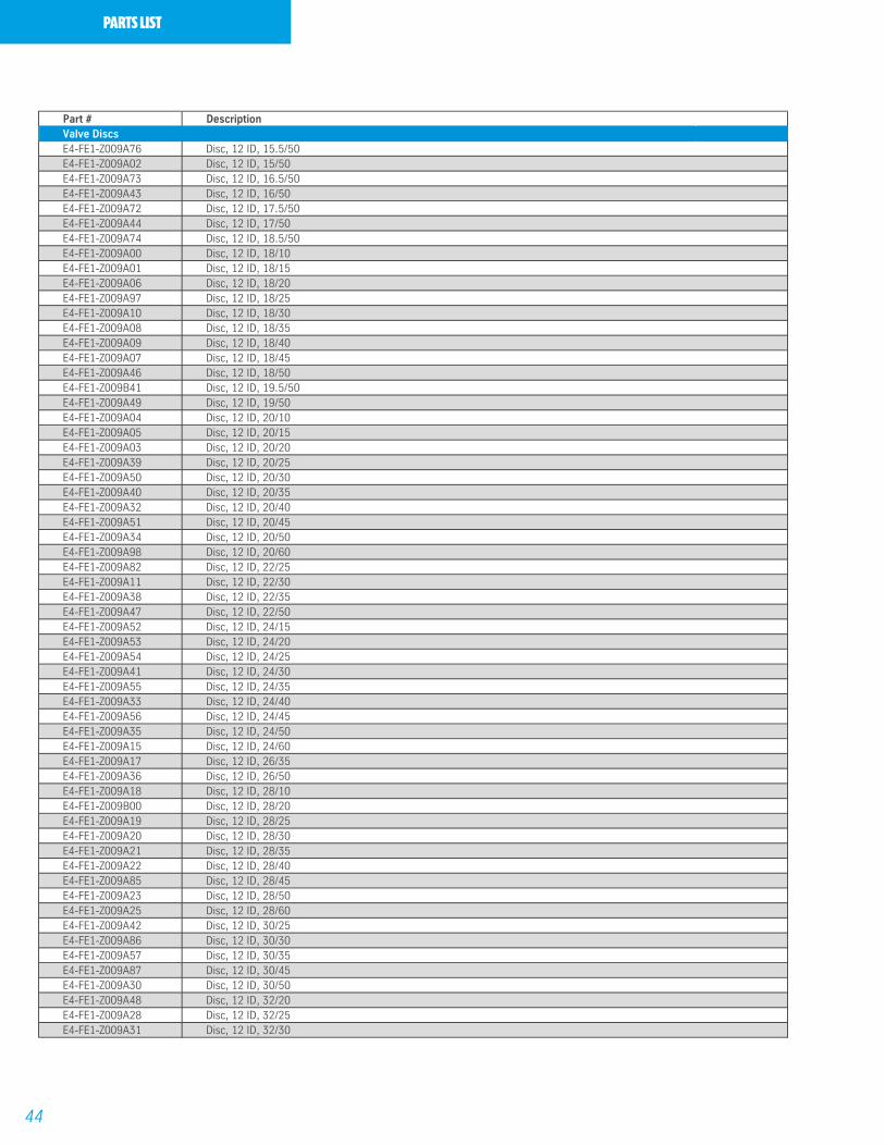
44
PARTS LIST
Part # Description
E4-FE1-Z009A76 Disc, 12 ID, 15.5/50E4-FE1-Z009A02 Disc, 12 ID, 15/50E4-FE1-Z009A73 Disc, 12 ID, 16.5/50E4-FE1-Z009A43 Disc, 12 ID, 16/50E4-FE1-Z009A72 Disc, 12 ID, 17.5/50E4-FE1-Z009A44 Disc, 12 ID, 17/50E4-FE1-Z009A74 Disc, 12 ID, 18.5/50E4-FE1-Z009A00 Disc, 12 ID, 18/10E4-FE1-Z009A01 Disc, 12 ID, 18/15E4-FE1-Z009A06 Disc, 12 ID, 18/20E4-FE1-Z009A97 Disc, 12 ID, 18/25E4-FE1-Z009A10 Disc, 12 ID, 18/30E4-FE1-Z009A08 Disc, 12 ID, 18/35E4-FE1-Z009A09 Disc, 12 ID, 18/40E4-FE1-Z009A07 Disc, 12 ID, 18/45E4-FE1-Z009A46 Disc, 12 ID, 18/50E4-FE1-Z009B41 Disc, 12 ID, 19.5/50E4-FE1-Z009A49 Disc, 12 ID, 19/50E4-FE1-Z009A04 Disc, 12 ID, 20/10E4-FE1-Z009A05 Disc, 12 ID, 20/15E4-FE1-Z009A03 Disc, 12 ID, 20/20E4-FE1-Z009A39 Disc, 12 ID, 20/25E4-FE1-Z009A50 Disc, 12 ID, 20/30E4-FE1-Z009A40 Disc, 12 ID, 20/35E4-FE1-Z009A32 Disc, 12 ID, 20/40E4-FE1-Z009A51 Disc, 12 ID, 20/45E4-FE1-Z009A34 Disc, 12 ID, 20/50E4-FE1-Z009A98 Disc, 12 ID, 20/60E4-FE1-Z009A82 Disc, 12 ID, 22/25E4-FE1-Z009A11 Disc, 12 ID, 22/30E4-FE1-Z009A38 Disc, 12 ID, 22/35E4-FE1-Z009A47 Disc, 12 ID, 22/50E4-FE1-Z009A52 Disc, 12 ID, 24/15E4-FE1-Z009A53 Disc, 12 ID, 24/20E4-FE1-Z009A54 Disc, 12 ID, 24/25E4-FE1-Z009A41 Disc, 12 ID, 24/30E4-FE1-Z009A55 Disc, 12 ID, 24/35E4-FE1-Z009A33 Disc, 12 ID, 24/40E4-FE1-Z009A56 Disc, 12 ID, 24/45E4-FE1-Z009A35 Disc, 12 ID, 24/50E4-FE1-Z009A15 Disc, 12 ID, 24/60E4-FE1-Z009A17 Disc, 12 ID, 26/35E4-FE1-Z009A36 Disc, 12 ID, 26/50E4-FE1-Z009A18 Disc, 12 ID, 28/10E4-FE1-Z009B00 Disc, 12 ID, 28/20E4-FE1-Z009A19 Disc, 12 ID, 28/25E4-FE1-Z009A20 Disc, 12 ID, 28/30E4-FE1-Z009A21 Disc, 12 ID, 28/35E4-FE1-Z009A22 Disc, 12 ID, 28/40E4-FE1-Z009A85 Disc, 12 ID, 28/45E4-FE1-Z009A23 Disc, 12 ID, 28/50E4-FE1-Z009A25 Disc, 12 ID, 28/60E4-FE1-Z009A42 Disc, 12 ID, 30/25E4-FE1-Z009A86 Disc, 12 ID, 30/30E4-FE1-Z009A57 Disc, 12 ID, 30/35E4-FE1-Z009A87 Disc, 12 ID, 30/45E4-FE1-Z009A30 Disc, 12 ID, 30/50E4-FE1-Z009A48 Disc, 12 ID, 32/20E4-FE1-Z009A28 Disc, 12 ID, 32/25E4-FE1-Z009A31 Disc, 12 ID, 32/30
Valve Discs
45
PARTS LIST
Part # Description
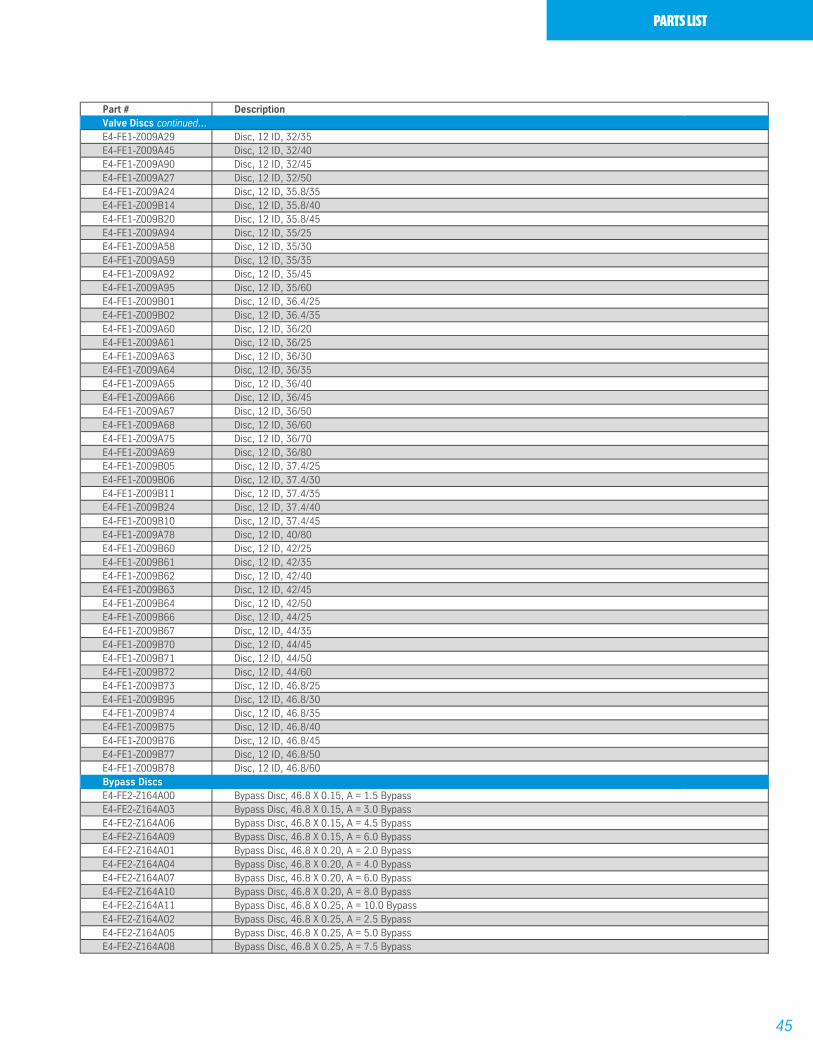
E4-FE1-Z009A29 Disc, 12 ID, 32/35E4-FE1-Z009A45 Disc, 12 ID, 32/40E4-FE1-Z009A90 Disc, 12 ID, 32/45E4-FE1-Z009A27 Disc, 12 ID, 32/50E4-FE1-Z009A24 Disc, 12 ID, 35.8/35E4-FE1-Z009B14 Disc, 12 ID, 35.8/40E4-FE1-Z009B20 Disc, 12 ID, 35.8/45E4-FE1-Z009A94 Disc, 12 ID, 35/25E4-FE1-Z009A58 Disc, 12 ID, 35/30E4-FE1-Z009A59 Disc, 12 ID, 35/35E4-FE1-Z009A92 Disc, 12 ID, 35/45E4-FE1-Z009A95 Disc, 12 ID, 35/60E4-FE1-Z009B01 Disc, 12 ID, 36.4/25E4-FE1-Z009B02 Disc, 12 ID, 36.4/35E4-FE1-Z009A60 Disc, 12 ID, 36/20E4-FE1-Z009A61 Disc, 12 ID, 36/25E4-FE1-Z009A63 Disc, 12 ID, 36/30E4-FE1-Z009A64 Disc, 12 ID, 36/35E4-FE1-Z009A65 Disc, 12 ID, 36/40E4-FE1-Z009A66 Disc, 12 ID, 36/45E4-FE1-Z009A67 Disc, 12 ID, 36/50E4-FE1-Z009A68 Disc, 12 ID, 36/60E4-FE1-Z009A75 Disc, 12 ID, 36/70E4-FE1-Z009A69 Disc, 12 ID, 36/80E4-FE1-Z009B05 Disc, 12 ID, 37.4/25E4-FE1-Z009B06 Disc, 12 ID, 37.4/30E4-FE1-Z009B11 Disc, 12 ID, 37.4/35E4-FE1-Z009B24 Disc, 12 ID, 37.4/40E4-FE1-Z009B10 Disc, 12 ID, 37.4/45E4-FE1-Z009A78 Disc, 12 ID, 40/80E4-FE1-Z009B60 Disc, 12 ID, 42/25E4-FE1-Z009B61 Disc, 12 ID, 42/35E4-FE1-Z009B62 Disc, 12 ID, 42/40E4-FE1-Z009B63 Disc, 12 ID, 42/45E4-FE1-Z009B64 Disc, 12 ID, 42/50E4-FE1-Z009B66 Disc, 12 ID, 44/25E4-FE1-Z009B67 Disc, 12 ID, 44/35E4-FE1-Z009B70 Disc, 12 ID, 44/45E4-FE1-Z009B71 Disc, 12 ID, 44/50E4-FE1-Z009B72 Disc, 12 ID, 44/60E4-FE1-Z009B73 Disc, 12 ID, 46.8/25E4-FE1-Z009B95 Disc, 12 ID, 46.8/30E4-FE1-Z009B74 Disc, 12 ID, 46.8/35E4-FE1-Z009B75 Disc, 12 ID, 46.8/40E4-FE1-Z009B76 Disc, 12 ID, 46.8/45E4-FE1-Z009B77 Disc, 12 ID, 46.8/50E4-FE1-Z009B78 Disc, 12 ID, 46.8/60
E4-FE2-Z164A00 Bypass Disc, 46.8 X 0.15, A = 1.5 BypassE4-FE2-Z164A03 Bypass Disc, 46.8 X 0.15, A = 3.0 BypassE4-FE2-Z164A06 Bypass Disc, 46.8 X 0.15, A = 4.5 BypassE4-FE2-Z164A09 Bypass Disc, 46.8 X 0.15, A = 6.0 BypassE4-FE2-Z164A01 Bypass Disc, 46.8 X 0.20, A = 2.0 BypassE4-FE2-Z164A04 Bypass Disc, 46.8 X 0.20, A = 4.0 BypassE4-FE2-Z164A07 Bypass Disc, 46.8 X 0.20, A = 6.0 BypassE4-FE2-Z164A10 Bypass Disc, 46.8 X 0.20, A = 8.0 BypassE4-FE2-Z164A11 Bypass Disc, 46.8 X 0.25, A = 10.0 BypassE4-FE2-Z164A02 Bypass Disc, 46.8 X 0.25, A = 2.5 BypassE4-FE2-Z164A05 Bypass Disc, 46.8 X 0.25, A = 5.0 BypassE4-FE2-Z164A08 Bypass Disc, 46.8 X 0.25, A = 7.5 Bypass
Bypass Discs
Valve Discs continued...

VALVING TRACKINGWORKSHEET.
Rebound / CompressionBrakeSupport#6Support#5Support#4Support#3Support#2Support#1Cover DiscBypassPistonBypassCover DiscSupport#1Support#2Support#3Support#4Support#5Support#6Brake
Rebound
Compression
46mm Valve Stacks
Rebound / CompressionBrakeSupport#6Support#5Support#4Support#3Support#2Support#1Cover DiscBypass PreloadPreloadPistonPreloadPreloadBypass Cover DiscSupport#1Support#2Support#3Support#4Support#5Support#6Brake
Rebound
Compression
60mm Valve Stacks
Looking for dependable performance suspension parts? Rely on Bilstein for quality and long-lasting products.