
(Original Instructions)€¦ · · 2015-03-17(Original Instructions) ... 4 Operating and...
18
4990627003 September 2013 GD175 ROTARY VANE COMPRESSOR Installation, Operating & Maintenance Manual (Original Instructions)
Transcript of (Original Instructions)€¦ · · 2015-03-17(Original Instructions) ... 4 Operating and...

4990627003September 2013
GD175ROTARY VANECOMPRESSOR
Installation, Operating &MaintenanceManual(Original Instructions)

Page �49906�7003 Date: 05/11 GD175 Installation, Operating & Maintenance Manual
1 Health & Safety Health & Safety Issues ....................................3
2 General2.1 Product General Description ..........................4 2.2 Power Options ................................................4 2.3 Storage/Low Use ............................................4 2.4 Dimensions, performance data, and operating environment ...........................6
3 Installation3.1 General ............................................................7 3.2 Mounting ........................................................7 3.3 Lifting ..............................................................8 3.4 Mounting orientations ....................................8 3.5 Lubrication ......................................................8 3.6 PTO and prop. shaft drive alignment .............9 3.7 Machine and PTO alignment ........................10 3.8 Pipe work ......................................................10 3.9 Ancillaries ......................................................12
4 Operating and commissioning4.1 Pre-operating check-list ................................13 4.2 Test/operating procedure ............................13 4.3 Driver Training ..............................................14
5 Maintenance5.1 Schedule .......................................................15 5.2 Checking the relief valve operation .............15 5.3 Inspecting the check (non-return) valve ......15 5.4 Silencers/Pipe work ......................................15 5.5 Lubrication ....................................................15 5.6 Air Inlet Filter .................................................16 5.7 Checking the blade wear ..............................17
Contents
Chapter Page

Page 349906�7003 Date: 05/11 GD175 Installation, Operating & Maintenance Manual
Health & Safety1 READ THE WHOLE MANUAL BEFORE COMMENCING INSTALLATION.
Static electricityEnsure, that where required, the compressor and ancillaries are earthed in accordance with BS5958 Part 1 1983; ‘Control of Undesirable Static Electricity’.
Powder-air combinations are potentially explosive.
Drive lineIt is the responsibility of the installer of the equipment to ensure all rotating and moving parts of the installation are adequately guarded to a standard which complies with the prevailing safety legislation.
CompressorThe compressor has internal moving parts some of which may be accessed through the inlet and outlet apertures. During operation cooling fans rotate beneath the cowls at each end of the machine and these can be accessed through the discharge aperture. Do not place any objects especially fingers into these apertures as personal injury could result.
InstallationA relief valve must be fitted in the outlet pipe work as close to the compressor as possible. The valve must be positioned so as not to vent air onto any personnel since the air discharged will be hot and can cause severe burns.
Storage/Low useBefore the machine is installed or when it will not be used for long periods:• Store in a dry, heated building. • Handle with care and keep the suction and delivery ports covered.• Rotate the drive shaft of the machine each week, in the direction shown by the arrow between the suction and delivery ports on the machine bodyWhere the compressor is mounted on a vehicle and located outside, it should be operated for at least 15 minutes each week (twice a week In damp/cool conditions)
Fire & HeatThe compressor includes seals made of fluoroelastomer polymers which degrade if exposed to temperatures above 300°C. If the material has been so exposed then it must not be handled with bare hands.
Surface temperatures can exceed 200°C. Highly combustable materials must not come into contact with the discharge pipework or compressor body.
Relief Valve CheckThis procedure should be carried out every month to clear the valve seat and check the valve is functional. (Ear protection is recommended)
NoiseGardner Denver Drums own tests show maximum noise levels for the GD175 should typically not exceed 90 dB(A) in the worst case (1600rpm 2.5bar g).
In accordance with our policy of continuous product improvement, Gardner Denver Drum reserve the right to alter details and specifications without notice.

Page 449906�7003 Date: 05/11 GD175 Installation, Operating & Maintenance Manual
2General
2.1 Product general description
The GD175 is a light-weight, compact rotary vane compressor designed for the oil free discharge of bulk liquids from general purpose tankers, e.g. liquid foodstuff, solvents, acids alkalis, hot bitumen, resins and other chemicals.
The main advantage of using a compressor to discharge liquids is that the product does not come into contact with the machine. This eliminates any problems of material compatibility with the liquid enabling a much wider variety of products to be discharged.
The machine is an oil free sliding/reciprocating vane design with the main stainless steel rotor being supported by bearing arrangements at either end.
All the components in the main bore cavity are manufactured from corrosion resistant materials to resist any possibility of atmospheric corrosion.
The very compact shape and size of the machine make it ideal for mounting inside the chassis to enable direct low-cost prop. shaft driving or via other drive methods more suitable for a particular application.
A through shaft allows CW or ACW input drive rotation and the compressor can be installed on any face to provide the maximum mounting flexibility.
The standard package consists of:Basic GD175 machine and mounting kitInduction kit including the GD175 inlet filterRelief valveCheck valveFlange pack
2.2 Power Options
The GD175 can be driven using any of the following drive systems.
Prop. shaft Direct from a gearbox mounted PTO
Hydraulically Several standard drives are available.
Electrically Motor drive packages on base frames/plates
Engine Drive packages on base frames/plates.
2.3 Storage/Low use
Before the machine is installed or when it will not be used for long periods:• Store the machine in a dry, heated building. • Handle the machine with care and keep the suction and delivery ports covered.• Rotate the drive shaft of the machine each week, in the direction shown by the arrow between the suction and delivery ports on the machine body. Where the compressor is mounted on a vehicle and located outside, it should be operated for at least 15 minutes each week (twice a week in damp/cool conditions).
Do not allow dirt, oil and grease to enter the machine ports as this could cause severe damage.
NOTE
NOTEThe shape and size of the machine make it particularly suitable for PTO/prop. shaft driving inside the vehicle chassis.

Page 549906�7003 Date: 05/11 GD175 Installation, Operating & Maintenance Manual
No. Description
1. Inlet Filter Kit - Flexible 2. GD175 Inlet Filter 3. Basic GD175 Machine 4. Relief Valve 5. Isolating Valve6. Check (Non-Return) Valve 7. Micronic Discharge Filter8. Alternative For Hard Piping
Figure1. Recommended Layout
General
“A”Dimension “A” to beMax. of 1.0 Metre
180mm

Page 649906�7003 Date: 05/11 GD175 Installation, Operating & Maintenance Manual
Figure 2. Dimensions
General
Ambient temperature range -40 to +50°C
Resistant to tropical rain (in operation and transit), salt and sun
Humidity level Up to 100% RH condensing
Vibration level 0 to 40 Hz; ± 40 mm amplitude tested.
Inlet depression Not to exceed 50 mbar
Orientation See fig 4 page 8
Max. outlet temperature 270°C
PORT DETAIL
SHAFT DETAIL
8 40 6
030
80 80
230
120
125
180
246
120
120
256 196
501
139 139
145145
Ø12
40 40
18
? 50 Ø70
2.4 Dimensions, Performance Data & Operating Environment
DimensionsThe dimensions of the compressor are shown in figure 2 below.
Performance The performance details and power requirements of the GD175 compressor are shown on the product data sheet.
For additional information, the constant running torque does not exceed:
78 Nm Speed range 1000 - 1600 rpm
Product Data can be found on the machine nameplate which is mounted on the side of the compressor as shown in figure 2a below.
Operating environmentThe permissible/foreseen operating environment is as follows:
Figure 2a. Machine Nameplate

Page 749906�7003 Date: 05/11 GD175 Installation, Operating & Maintenance Manual
3Installation
3.1 GeneralFor the recommended layout of the machine and ancillaries, see figure 1.
When selecting the machine mounting position, the following points should be considered:
• Direction of input rotation to the machine must be correct and is simple to change by swapping over the plastic cowls (see section 3.6 for how to change the machine input rotation) and driving the shaft at the other end of the machine.• Install away from sources of heat, e.g. vehicle exhaust air or hot pipes that could effect the compressor temperature in any way.• Venting relief/control valve air must be unobstructed and direct to the atmosphere.• The relief valve should be fitted as close as possible to the GD175 discharge port and before any other discharge ancillary (See Figure 1).• Any valves should be positioned to avoid hot air venting onto the operator.• A cooling fan is fitted at each end of the machine and the cooling air path into the fan must not be obstructed.• A space of at least 25mm must be allowed around the machine for air circulation. If mounting to a solid plate, the machine should be mounted at least 25mm from the plate or a cooling hole should be cut into the plate. • Any flexible coupling assembly used with the machine (e.g. on hydraulic drives) must incorporate shaft end clearance (at least 1mm) to avoid interference through temperature expansion during operation.
3.2 MountingEach mounting foot is attached to the machine using two long capscrews (Fig 3, Item 2) and washers (Fig 3, Item 3) with the location bushes (Fig. 3, Item 4), waved washers (Fig. 3, Item 5) and mounting bushes (Fig. 3, Item 6) fitted between the mounting feet (Fig 3, Item 1) and the cowls.
The location bushes (Fig 3, Item 4) are a press fit into the mounting feet.
The mounting bushes (Item 6) have axial play controlled by the waved washers (Item 5) to allow thermal expansion during operation.
12mm diameter holes are provided in the bottom of feet to allow 10mm studs, screws and nuts (all grade 8.8 or higher) to be used for securing the machine.
The feet should be fixed to a flat surface to avoid inducing unnecessary stresses into the machine and mounting feet. This can be achieved using shimming if necessary. Check the feet are parallel to the mounting bush and the clearance for the waved washer is equal all round.
Operating in reverse, even for a short period, can cause severe damage to the machine
No. Description
1. Mounting foot 2. Cap Screw, M10 3. Washer, M10 4. Location Bush5. Waved Washer6. Mounting Bush
Figure 3. Foot mounting details
CAUTION
NOTEOnly the longer capscrews supplied with the feet must be used for securing the feet to the machine.
All fasteners should be tightened to 35 Nm.
14
56
32
Page �49906�7003 Date: 05/11 GD175 Installation, Operating & Maintenance Manual
Installation
3.5 Lubrication
The GD175 is supplied complete with sealed greased bearings. Bearing re-lubrication should be conducted in combination with the vane replacement procedure. See service instructions for further details.
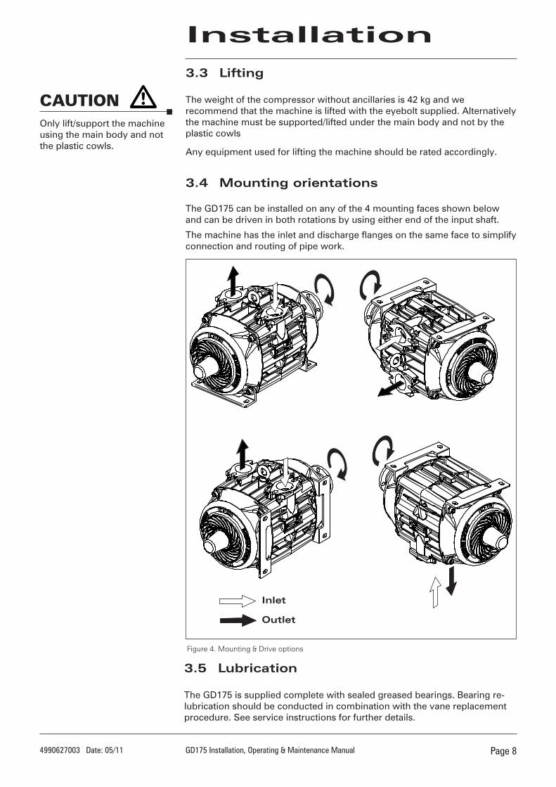
3.3 Lifting
The weight of the compressor without ancillaries is 42 kg and we recommend that the machine is lifted with the eyebolt supplied. Alternatively the machine must be supported/lifted under the main body and not by the plastic cowls
Any equipment used for lifting the machine should be rated accordingly.
3.4 Mounting orientations
The GD175 can be installed on any of the 4 mounting faces shown below and can be driven in both rotations by using either end of the input shaft.
The machine has the inlet and discharge flanges on the same face to simplify connection and routing of pipe work.
Figure 4. Mounting & Drive options
Only lift/support the machine using the main body and not the plastic cowls.
CAUTION
Inlet
Outlet

Page 949906�7003 Date: 05/11 GD175 Installation, Operating & Maintenance Manual
3.6 PTO and prop. shaft drive alignment.
Changing the machine rotationThe current direction of input rotation is indicated by cast arrows on the compressor body. Changing rotation is a simple process of swapping over the plastic cowls, key & drive flange as shown in the diagram below.
Installation
Figure 6. Drive Flange Removal
Fitting the drive flangeStandard drive flanges (and fasteners) are available with all new packages to fit either end of the rotor shaft.
It is important to use an OEM supplied flange to ensure the correct shaft fit & prevent damage to the machine during installation.
Before fitting, the shaft and flange should be clean and damage free to ensure it fits correctly.
Both the shaft and coupling bore should be smeared with a light oil during assembly to aid future separation.
A Hollow Set Screw (Grub Screw) should be used for retaining the drive flange, in position on the shaft.
Apply Loctite 270 to the Grub Screw and tighten to a torque of 7.2Nm.
A puller type device will be required to remove the flange (see Fig. 6) to help avoid damaging the shaft or flange.
Figure 5. Changing Rotation
The machine rotor must always rotate in the same direction, but the opposite input drive rotation can be achieved by driving the rotor from the other end of the machine.
NOTE
No. Description
1. Cap Screw, M10 2. Washer, M10 3. Mounting Foot 4. Location Bush5. Waved Washer6. Mounting Bush7. Plastic Cowl - NDE 8. GD175 9. Plastic Cowl - DE 10. Drive Flange 11. Key

Page 1049906�7003 Date: 05/11 GD175 Installation, Operating & Maintenance Manual
Installation
3.7 Machine and PTO Alignment
The drive axis on the majority of PTO’s is at 3 - 5° to the horizontal, which reflects the angle of the engine and gearbox.
The compressor should be mounted so that its drive axis is parallel to the PTO’s drive axis (within 1 degree) - see fig 7 .
The compressor should also be mounted so that the prop. shaft angle between the PTO and GD175 in any plane (including compound angles) is less than or equal to 12°.
Consideration should be given to the prop. shaft length when mounting the machine and the prop. shaft should be sized so that it always has sliding clearance.
Also check the prop shaft manufacturers information for the permitted installed angle.
NOTE
Equal Angle
3.8 Pipe work - Figures 1 & 8 show typical pipe work layouts
Standard inletA flexible inlet pipe, inlet filter, machine inlet flange and gasket are all provided in the inlet induction kit.
Fabricated pipeworkWhere any pipe work is to be fabricated, the following points should be followed/noted to prevent damage to the machine:
• A stainless steel slip-on-weld flange is provided with the machine for use with 38mm (1.5”) nominal bore pipe work.
• Inlet pipe work should be made in stainless steel or thick wall aluminium to help prevent corroded particles entering the machine.
• Outlet pipe work can be fabricated from any material (including mild steel) to suit the application, although stainless steel is recommended.
• All fabricated pipe work should be carefully de-scaled/cleaned before commissioning the compressor.
• Pipe work should be attached to the vehicle chassis using flexible mountings to prevent unnecessary vibration, expansion stress, noise transfer and avoid distorting the machine body.
• A flexible element is recommended in the discharge pipe work (and inlet pipe work when necessary) to absorb any pipework distortion created through chassis movement and heat expansion.
• All inlet and discharge pipe work should be as free from bends as possible to minimise pressure drops. This allows the machine to work in the best inlet conditions and provide the maximum discharge pressure.
Figure 7. Drive Alignment
Note: The combined angle in any plane should not exceed 12˚

Page 1149906�7003 Date: 05/11 GD175 Installation, Operating & Maintenance Manual
Installation
Figure 8. General Arrangement.
*
*
**
#3 *
**
*
*
Ref Qty Description1 1 Basic GD175 Machine
2 2 Gasket, Oval
3 1 Flange, Oval Stainless Steel
4 4 Screw, Set Hex M10 X 45
5 4 Washer, Plain M10
6 4 Nut, Self locking M10
7
7a7b7c7d
7e7f7g7h
1
1
1
INLET FILTER KIT Consisting of:
INLET FILTER KIT (5”) including:
1 off Raincap 1 off Mounting Band 1 off Indicator 1 off Filter Assembly
INLET HOSE KIT Including:
1 off Duct & Moulded Cuff 1 off Screw on Cuff 1 off Hose Clip 60/80 1 off Hose Clamp 50/70
8 1 Flange, Inlet (DN50)
9 1 Valve, Check 1½" BSP Female 'S'
10 1 Valve, Relief ½" (2.5 BAR)
11 1 Washer, Joint ½" BSP
12A 1 Flange, Drive
12B 1 Grub Screw, Drive Flange
#1 1 Customer supplied pipework & fittings.A flexible element is recommended in thedischarge pipework to prevent distortion of the machine from the fabricated pipework through chassis movement and any heat expansion.
#2 1 Customer Supplied Pressure Gauge:Gauge Range: 0 - 2.5 Barg
#3 1 Customer Supplied Isolating Valve
#4 1 Customer Supplied Alternative Hard Piping
#5 1 Customer Supplied Flexible Piping Element
Not provided in standard kit*
Page 1�49906�7003 Date: 05/11 GD175 Installation, Operating & Maintenance Manual
Installation
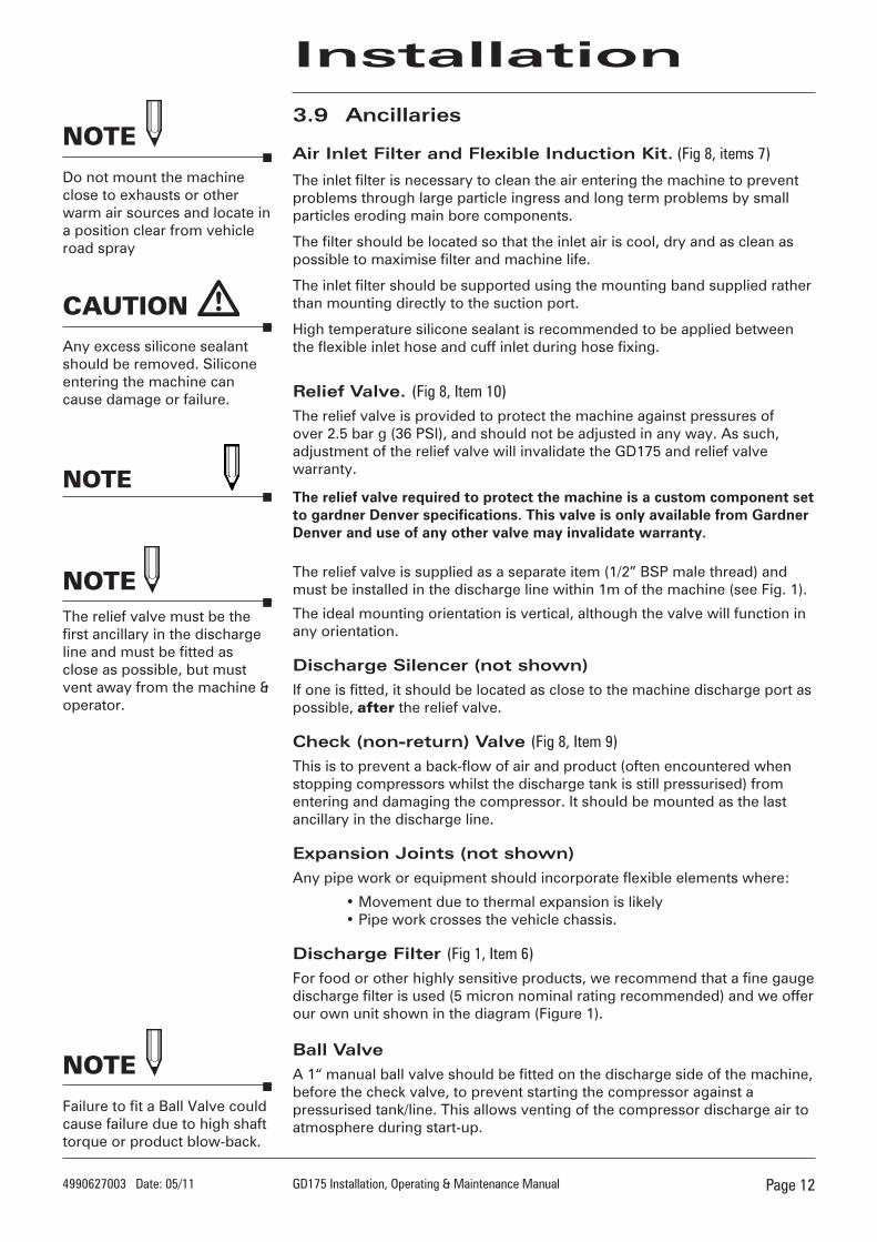
3.9 Ancillaries
Air Inlet Filter and Flexible Induction Kit. (Fig �, items 7)
The inlet filter is necessary to clean the air entering the machine to prevent problems through large particle ingress and long term problems by small particles eroding main bore components.
The filter should be located so that the inlet air is cool, dry and as clean as possible to maximise filter and machine life.
The inlet filter should be supported using the mounting band supplied rather than mounting directly to the suction port.
High temperature silicone sealant is recommended to be applied between the flexible inlet hose and cuff inlet during hose fixing.
Relief Valve. (Fig �, Item 10)The relief valve is provided to protect the machine against pressures of over 2.5 bar g (36 PSI), and should not be adjusted in any way. As such, adjustment of the relief valve will invalidate the GD175 and relief valve warranty.
The relief valve required to protect the machine is a custom component set to gardner Denver specifications. This valve is only available from Gardner Denver and use of any other valve may invalidate warranty.
The relief valve is supplied as a separate item (1/2” BSP male thread) and must be installed in the discharge line within 1m of the machine (see Fig. 1).
The ideal mounting orientation is vertical, although the valve will function in any orientation.
Discharge Silencer (not shown)If one is fitted, it should be located as close to the machine discharge port as possible, after the relief valve.
Check (non-return) Valve (Fig �, Item 9)This is to prevent a back-flow of air and product (often encountered when stopping compressors whilst the discharge tank is still pressurised) from entering and damaging the compressor. It should be mounted as the last ancillary in the discharge line.
Expansion Joints (not shown)Any pipe work or equipment should incorporate flexible elements where:
• Movement due to thermal expansion is likely • Pipe work crosses the vehicle chassis.
Discharge Filter (Fig 1, Item 6)For food or other highly sensitive products, we recommend that a fine gauge discharge filter is used (5 micron nominal rating recommended) and we offer our own unit shown in the diagram (Figure 1).
Ball ValveA 1“ manual ball valve should be fitted on the discharge side of the machine, before the check valve, to prevent starting the compressor against a pressurised tank/line. This allows venting of the compressor discharge air to atmosphere during start-up.
NOTEThe relief valve must be the first ancillary in the discharge line and must be fitted as close as possible, but must vent away from the machine & operator.
NOTEDo not mount the machine close to exhausts or other warm air sources and locate in a position clear from vehicle road spray
NOTEFailure to fit a Ball Valve could cause failure due to high shaft torque or product blow-back.
Any excess silicone sealant should be removed. Silicone entering the machine can cause damage or failure.
CAUTION
NOTE

Page 1349906�7003 Date: 05/11 GD175 Installation, Operating & Maintenance Manual
4 Tick when completed
Commissioning
4.1 Pre-operating check list
Flexible and welded pipe bores etc cleaned after fabrication.
All flanges, fasteners and mountings secure.
Vehicle PTO disengaged.
Engine management system set-up correctly for the application.
Blow (ball) valve open (if starting against a tank pressure).
Commissioning/testing 1.5 - 2”gate valve and silencer fitted.
Discharge pressure gauge fitted (0-3 bar g)
Ancillaries correctly fitted and sequenced as per instructions
1 Check that the gate valve on the discharge pipework is open.
2 Start the engine, depress the clutch and allow the vehicle gearbox parts to stop rotating (5 seconds should be sufficient).
3 Engage the PTO and slowly raise the clutch, then set the engine speed to drive the compressor at the operating speed of the application. Note: The compressor input speed range is 1000 - 1600 rpm.
4 Check that the inlet blockage indicator does not indicate (show red) a blocked filter/inlet pipe work (see inlet filter section)
5 Whilst the compressor is operating, check the pipe work for leaks. Stop the machine and tighten fasteners if necessary.
6 Partially close the gate valve to raise the discharge pressure to 0.2 bar below the relief valve full bypass setting (stamped on relief valve). Check the system for leaks. Stop the machine and tighten fasteners if necessary.
7 If all is well, continue to run the compressor until the total test time reaches 30 minutes. Re-check for air leaks.
8 Slowly increase the pressure beyond the stamped setting (on valve) to operate the relief valve.
The relief valve should crack (begin to lift/open/blow off) within 10% below the set pressure. Slight leakage prior to cracking is permitted at up to 0.5 bar g below the set pressure.
The relief valve should then fully open (full bypass) within 150mbar of the set pressure.
9 Slowly reduce the pressure until the relief valve re-seats (should be before 0.5 bar g (7 psi) under the full bypass pressure).
10 Check that all fastenings are still tight and flanges are leak free.
11 Return the engine speed to tick over, disengage the PTO, and then stop the engine.
12 Remove any test apparatus, disconnect the discharge hose and fit a blanking cap.
4.2 Test and operating procedure
Max.DischargePressure 2,5 bar g (36 psi)
Max.InletDepression50mbar under all circumstances.
CAUTIONGardner Denver Drum’s own tests show noise levels fall between 84-90 dB(A) at 1 metre and ear protection is recommended for long periods of exposure.
Never start the compressor against a pressurised tank or discharge line.
CAUTION
Tick when completed
CAUTIONPipework will become HOT during test/running.

Page 1449906�7003 Date: 05/11 GD175 Installation, Operating & Maintenance Manual
4.3 GD175 Driver training
Driver training should be given whenever possible and should include:-
SafetyInstruct the driver regarding:
• Rotating parts
• Hot Pipework
• Pressure Relief valve
• Safety couplings
OperationInstruct the driver regarding:
• Speed range
• Maximum operating pressure
• PTO engagement
• Unloading valve
Routine MaintenanceInstruct the driver regarding:
• Air filter - cleaning
• Pipe connections - checking
• Mounting fasteners - checking
• Relief valve function
• Check valve function
Commissioning

Page 1549906�7003 Date: 05/11 GD175 Installation, Operating & Maintenance Manual
5Daily • Monitor the inlet filter blockage indicator.
Weekly • Clean the fans, fan covers and body ribs.
• Check air filter and pipe work for leaks.
Where the compressor is mounted on a vehicle and located outside, it should be operated for at least 15 minutes each week (twice a week In damp/cool conditions)
Monthly • Check Function of Relief and Check (non-return) Valve
• Check inlet and discharge pipe work for leaks.
3 Monthly • Clean filter carcass and element - Air Filter element and carcass - replace if necessary.
• Check security of compressor feet fixing bolts to both machine and chassis. Tighten if necessary (M10 bolts - torque to 35 Nm)
6 Monthly • Check blade wear
Annually • Replace Air Filter Element
• Examine the internals of the check valve
• Examine pipes, silencers and pipework fixings for corrosion and replace as required
Maintenance
5.1 Schedule
Tamperproof lead seals have been fitted into the cap screw heads on each sideplate. Removal of these seals during the warranty period will invalidate the warranty.
5.2 Checking the relief valve operation
Check the relief valve operation as detailed in section 4 and visually check for any sign of obvious defects.
5.3 Inspecting the check (non-return) valve
The check (non-return) valve should be removed and visually checked for signs of wear. If in any doubt, replace the entire valve.
5.4 Silencers / Pipe work
Silencers (if fitted) and pipework should be inspected for signs of damage or corrosion. When paintwork is damaged, clean off any corrosion and treat with rust inhibitor before repainting. Use paints that can withstand temperatures of 240°C.
5.5 Lubrication
The bearings are packed with grease on assembly and need no regular attention.
See separate service instructions for machine overhaul & Regreasing.
The relief valve should be operated every month to clear the valve seat and check the valve is functional.
(Ear protection is recommended)
NOTE
If the maximum pressure reading is higher than the set pressure by more than 0.2 bar, stop the test and replace the relief valve before running the compressor again.
NOTE
The compressor can be carefully cleaned with steam or water jets, but only when the machine is cold as serious damage could result.
NOTE
NOTENew gaskets may be required when inspecting the check valve.

Page 1649906�7003 Date: 05/11 GD175 Installation, Operating & Maintenance Manual
5.6 Air inlet filter
The blockage indicator is designed to show/hold the maximum inlet blockage encountered. It is set to show 100% blockage when the inlet depression reaches 50mbar.
If the indicator valve has entered the red portion of the scale (when the compressor is operating), the filter must be cleaned or replaced by employing one or both of the following processes:
Remove accumulated filter debris (machine not running)
1. Pull back the clips retaining the air inlet filter end cap and remove the end cap.
2. Empty out any dust or dirt and clean out the main filter cavity. Replace the end cap the correct way up and re-clip in position.
Clean the filter element
To clean the filter element (machine not running):
1. Remove the air filter end cap (as described in the previous section).
2. Withdraw the filter from the filter body.
3. Clean the filter by blowing compressed air through the inside of the element.
4. Element replacement is a direct reversal of the above.
Filter elements should be replaced every 12 months or sooner if cleaning does not return the blockage indicator to the unblocked condition.
Figure 9. Replacing Air Filter
Maintenance
Figure 10. Blockage Indicator
No. Description
1. Filter Body 2. End Cover 3. Filter Element 4. Raincap 5. Filter Blockage (Condition) Indicator 6. Vacuator Valve 7. Retaining Clips 8. Hose Clamp 9. Inlet Hose & Cuff

Page 1749906�7003 Date: 05/11 GD175 Installation, Operating & Maintenance Manual
Maintenance
5.7 Checking the blade wear
Using the drawing (fig 11) below, check the blade wear as follows:
1. Remove the pipework from the suction port.2. Turn the rotor, in the direction of rotation, until one of the blade slots can be seen through the port.
3. Push the blade down to the bottom of the slot and measure, parallel to the slot, the distance from the blade to the top edge of the port (dimension ‘A’ shown below) using a vernier caliper or other suitable device.
4. The performance of the machine will begin to deteriorate when this measurement reaches 100 mm (i.e. blade width is 55mm).
5. Once the measurement has reached 100mm the blades must be replaced.
Refer to separate service instruction manual for further details on blade replacement
Failure to replace the blades in line with the recommendations will eventually result in machine failure. Late blade change can permanently damage the machine so that future blade life is reduced.
NOTE
A
Measuring Device
“A”
Measuring Device
Replace Blades When“A” = 100mm.
Figure 11. Checking Blade Wear.
When carrying out the measurement ensure that the measuring device is parallel with the vane slot when resting on the edge of the suction port.This will ensure that the dimension taken is as accurate as possible.
NOTE
For additional information, contact your local representative or
Gardner Denver LtdPO Box 178,
Springmill Street, Bradford,
West Yorkshire, UK BD5 7YH
Tel: +44 (0)1274 718100Fax: +44 (0)1274 655272
Email: [email protected] Web: www.gd-transport.com
© 2013 Gardner Denver Ltd.
BelgiumGardner Denver Belgium N.V.Luithagen 7AHaven 200B-2030 AntwerpenBelgiumPhone: +32 (0)3 5415040Fax: +32 (0)3 5416509
email: [email protected]
AmericasGardner Denver, Inc.Industrial Products Group - Americas1800 Gardner ExpresswayQuincy, IL. 62305Toll Free: 1-800-682-9868Phone: 217-222-5400Fax: 217-221-8780
email: [email protected]
NetherlandsGardner Denver Nederland BVBarwoutswaarder 3B3449 He WoerdenThe NetherlandsPhone: +31 (0)348410150Fax: +31 (0)348418079
email: [email protected]
AustraliaGardner Denver Ind. Australia Pty Ltd30 Bearing RoadSeven HillsNew South Wales2147 AustraliaPhone: +61 2 96207000Fax: +61 2 96207955
email: [email protected]
FranceGardner Denver France SADivision Compresseurs42, rue du Montmurier, BP 60438070 Saint-Quentin-Fallavier, FrancePhone: +33 (0)474941673Fax: +33 (0)474941689
email: [email protected]
UK Sales & ServiceGardner Denver UK LtdPO Box 468Cross Lane, TongBradford, West YorkshireUnited KingdomBD4 0SUPhone: +44 (0)1274 683131Fax: +44 (0)1274 651006email: [email protected]
Rest of the WorldGardner Denver LtdPO Box 178Springmill StreetBradford, West YorkshireUnited KingdomBD5 7YHPhone: +44 (0)1274 718100Fax: +44 (0)1274 655272email: [email protected]
GermanyGardner Denver Deutschland GmbHAm Dorn 1448308 SendenGermanyPhone: +49 (0)253634840Fax: +49 (0)25363484010
email: [email protected]
SpainGardner Denver Iberica S.L.Calle Primavera, 20Poligono Industrial Las Monjas28850 Torrejon de ArdozMadrid, SpainPhone: +34 (0)916560056Fax: +34 (0)916770496
email: [email protected]
Contact Us