Translation of the original Operating instructions - · PDF fileTranslation of the original...
25
ADS-70 1 Translation of the original Operating instructions Valid since: 2010/09/15 Technical modifications reserved. Ammann Verdichtung GmbH Josef Dietzgen-Str. 36 D-53773 Hennef Telefon 02242 / 88020 Telefax 02242 / 880259 e-mail: [email protected] www.ammann-group.com Printed in Germany Diesel rammer ADS-70
Transcript of Translation of the original Operating instructions - · PDF fileTranslation of the original...

ADS-70 1
Translation of the original Operating instructions
Valid since: 2010/09/15 Technical modifications reserved.
Ammann Verdichtung GmbH
Josef Dietzgen-Str. 36
D-53773 Hennef Telefon 02242 / 88020 Telefax 02242 / 880259 e-mail: [email protected] www.ammann-group.com Printed in Germany
Diesel rammer
ADS-70

EG-KonformitätserklärungEC-Declaration of Conformity / Déclaration „CE“ de Conformité / Declaración de conformidad de la CE
gemäß Maschinen-Richtlinie 2006/42/EG, Anhang II A und Geräuschrichtlinie 2000/14/EG
as defined by the Machinery directive 2006/42/EC Annex II A and Noise directive 2000/14/ECconformément à la directive „CE“ relative aux machines 2006/42/CE, Annexe II A et la directive du bruit 2000/14/CE
conforme a la directiva de maquinaria 2006/42/CE, Anexo II A y a la directiva sobre ruidos 2000/14/CE
Hersteller (Name und Anschrift):
Manufacturer (name and adress):Fabricant (nom et adress):Fabricante (nombre y dirección):
Ammann Verdichtung GmbHJosef-Dietzgen-Straße 36D-53773 Hennef
Vibr.-Stampfer / Vibr. rammer / Pilonneuse vibrante / Apisonadora vibratoria
Hiermit erklären wir, dass die Maschine (Typ)Herewith we declare that the machine (Type)Par la présente, nous déclarons que la machine (Type)Por la presente, declaramos que la máquina (Tipo)
Leistung / Output / Puissance / Potencia:
ACR 60
Honda GX100
2.2 kW
ACR 68
Honda GX100
2.2 kW
ADS 70
Yanmar L48AE
3.2 kW
Seriennummer:Serial number:Numéro de série:Número de serie:
weitere Informationen siehe Typenschildlook at machine plate for more informationinformations détaillés sur plaque typepara más información consulte la placa de características
folgenden einschlägigen Bestimmungen entspricht:complies with the following provisions applying to it:correspond aux dispositions pertinentes suivantes:corresponde a las siguientes disposiciones pertinentes:
2006/42/EG2006/42/EC2006/42/CE2006/42/CE
2000/14/EG2000/14/EC2000/14/CE2000/14/CE
2005/88/EG2005/88/EC2005/88/CE2005/88/CE
2004/108/EG2004/108/EC2004/108/CE2004/108/CE
Angewandte harmonisierte Normen :Applied harmonized standards:Normes harmonisées appliquées:Normas armonizadas aplicadas:
EN 500-1 ; EN 500-4
Die benannte Stelle nach 2000/14/EGThe notified body of 2000/14/ECL’organisme habilité de 2000/14/CEEl organismo citado según 2000/14/CE
TÜV RheinlandProduct Safety GmbHD-51101 KölnKenn-Nr. 0197
wurde (wird) eingeschaltet zur / was (is) engaged for / intervient pour / ha (habrá) intervenido para:
Konformitätsbewertung nach Anhang VIII aus 2000/14/EGvaluation of conformity to Annex VIII of 2000/14/ECconformément à l’Annexe VIII de 2000/14/CEla evaluación de conformidad, según Anexo VIII de 2000/14/CE
ISO 9001 Zertifikats-Nr.:ISO 9001 certificate No.:ISO 9001 attestation n
o:
ISO 9001 nº de certificado:
09100 67054
Gemessener Schallleistungspegel LWA,m
Measured sound power level LWA,m
Niveau de puissance de son LWA,m
Nivel de potencia sonora medido LWA,m
105 dB 105 dB 106 dB
Garantierter Schallleistungspegel LWA,g
Guaranted sound power level LWA,g
Niveau de puissance de son garanti LWA,g
Nivel de potencia sonora garantizado LWA,g
108 dB 108 dB 108 dB
Hennef, 20.08.2010 ppa. Dipl.-Ing. Reiner Schulz, Technische Leitung
Ort, DatumPlace, date / Lieu, date / Lugar, fecha
Unterschrift, Angabe der Funktion im UnternehmenSignature, acting in the company / Signature, en qualitè de /
Firma, en calidad de Assinatura
Aufbewahrung der technischen Unterlagen bei o.g. Person
Technical documents are kept by the above mentioned personConservation des documents techniques par la personne susmentionnée
La persona arriba indicada guarda la documentación técnica
Ammann Verdichtung GmbH | Josef-Dietzgen-Straße 36 | D-53773 Hennef | Tel. +49 (0) 2242 / 88 02-0 | Fax +49 (0) 2242 / 88 02-59
Geschäftsführer : Bernd Holz; Christian Stryffeler | HRB 1949 Amtsgericht Siegburg | [email protected] | www.ammann-group.com

ADS-70 2
Foreword : The field-experienced development and construction as well as the manufacturer’s long years of experience in the production of vibration rammers are the guarantee for very best quality and utmost reliability of your machine. This operating and service manual includes the following contents:
• safety regulations • maintenance instructions • description of the machine • maintenance schedule • operating instructions Respecting this manual
• makes it easier to get to know the machine. • helps avoid malfunctions or disturbances due to improper use. Keeping to the maintenance instructions
• increases the rammer’s reliability during operation on job sites, • prolongs the machine’s working life, • helps reduce repair costs and downtimes. Ammann-Maschinenbau GmbH cannot assume any liability for the functioning of the machine
• if it is operated in a manner that does not correspond to the proper operating instructions, • if it is used in fields of application for which it is not provided and which do not correspond to proper use (see paragraph 3.1) and which differ from the proper fields of application (paragraph 2.1). No warranty can be claimed if :
• mistakes are made in operation • no maintenance checks and/or works are carried out, • wrong fuel is used.
Note : - This manual has been written for operating and service staff on the job sites. - This operating and maintenance manual is to be kept ready to hand near the machine. - Operating the rammer is only allowed after the operator has been trained on it and in accordance with the present instructions. - The safety regulations described in paragraph 3.0 on pages 9 to 13, the „Safety guidelines
for the operation of road rollers and ground compactors“, issued by the Civil Engineering Employer’s Liability Insurance Association, and the rules for prevention of accidents must absolutely be observed.
For your own safety and in order to avoid disturbances of the machine’s functioning, only Ammann spare parts must be used (paragraph 2.2 „Modifications on the machine“). The spare parts list and operating manual can also be supplied in different languages through your Ammann dealer by indicating the rammer’s serial number. The warranty and liability conditions as provided in Ammann Verdichtung GmbH’s General Terms and Condi-tions are neither extended nor substituted by the above-mentioned or following remarks. Ammann Verdichtung GmbH
ADS-70 3
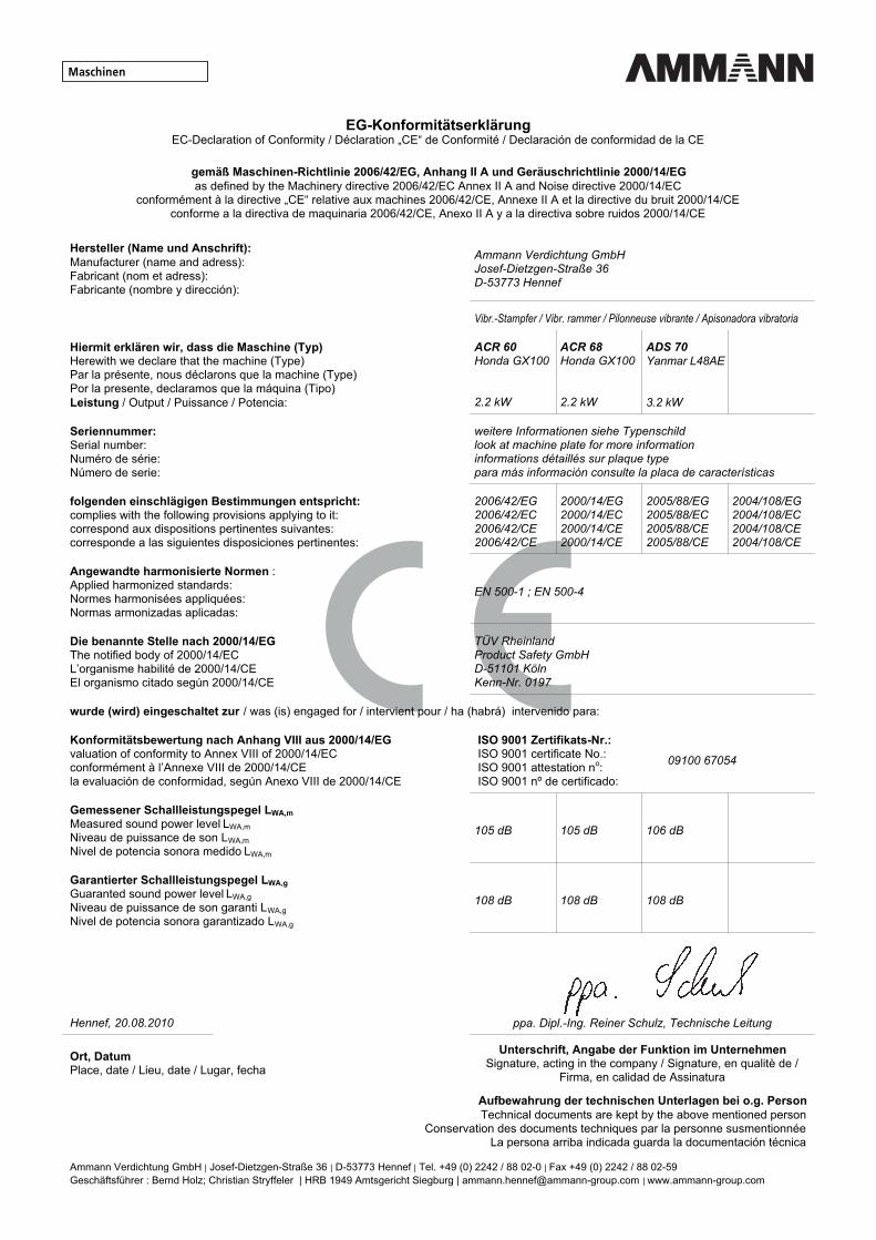
Foreword : Please fill in when handing over the machine : ...................................................................... 1. Rammer model ...................................................................... 2. Serial number ...................................................................... 3. Engine model ...................................................................... 4. Engine serial number
Attention : When taking over the rammer, you will be trained in operation and maintenance by one of our employees or by our dealer. Here, it will be absolutely necessary to respect the safety
remarks and danger warnings.

ADS-70 4
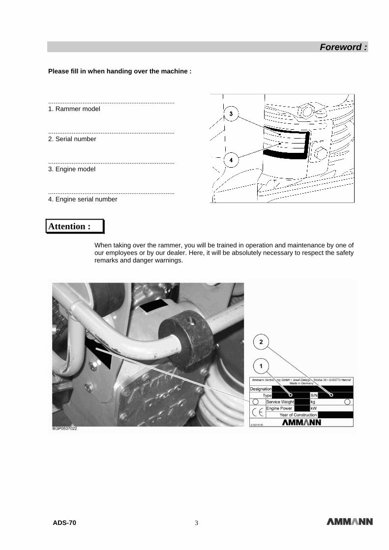
Table of contents : 1.0 Technical specifica-tions
5
1.1 Main dimensions 5 1.2 Technical specifications 5 1.3 Noise and vibration values 6
2.0 Description 7
2.1 Fields of application 7 2.2 Modifications on the machine 7
3.0 Safety regulations 9
3.1 Proper use 10 3.2 Operating the vibration rammer 10 3.3 Safety remarks in the operating/maintenance manual 10 3.4 Warning stickers on the vibration rammer 11 3.5 Loading the vibration rammer 11 3.6 Starting the vibration rammer 11 3.6.1 Before start-up 11 3.6.2 Start-up 11 3.6.3 Start-up in closed rooms 12
3.7 Working with the vibration rammer 12 3.7.1 Persons in the danger area 12 3.7.2 Moving the vibration rammer 12 3.7.3 Moving the vibration rammer on slopes 12 3.7.4 Conduct in traffic 12 3.7.5 Checking the effects of vibration 12 3.7.6 Parking the vibration rammer 12 3.7.7 Parking the vibration rammer on slopes 12
3.8 Taking in fuel 13 3.9 Maintenance works 13 3.9.1 Working on the engine 13 3.9.2 Cleaning works 13 3.9.3 After the maintenance works 13
3.10 Repair 13
4.0 Loading and transport 15
5.0 Operation 15
5.1 Control before use 15 5.2 Refuelling 15 5.3 Starting the engine 16 5.4 Cold start device 16 5.5 Working with the vibration rammer 17 5.6 Adjustment during breaks 17 5.7 Stopping the engine 17
6.0 Recommendations for compaction works with DS 68
17
7.0 Maintenance 7.1 General remarks on maintenance/maintenance work 18 7.2 Instructions for running-in 18 7.3 Diesel engine 18 7.4 Changing the oil in the tamping system 19 7.5 Cleaning the diesel filter 19 7.6 Checking, cleaning and replacing the air filter 20
8.0 Screw torques 21
9.0 Maintenance schedule 22

ADS-70 5
Technical specifications :
1.1 Main dimensions ADS-70
Dimension A B C D E Mm 340 280 670 360 980 Fig. 4
Fig. 5
1.2 Technical specifications ADS 70
Weight 83 kg Lenght of butt plate 340 mm Width of butt plate 280 mm Overall length 670 mm Overall width 360 mm Engine Yanmar L48AE diesel engine
with 3.2 kW/4.3 hp at Engine speed 3250 rpm Cooling air cooled Number of impacts 730 min-1 Jump height up to 60 mm Surface capacity up to 210 m2/h Impact force 16 kN Impact energy 95 J Travel speed up to 12 m/min Filling capacities : Fuel tank 2,5 l Oil inside the butt plate 1,5 l
ADS-70 6
Technical specifications :
1.3 Noise and vibration values
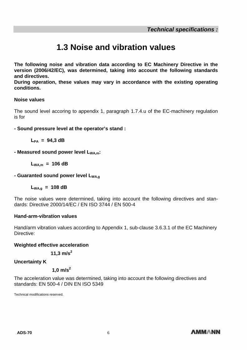
The following noise and vibration data according to EC Machinery Directive in the version (2006/42/EC), was determined, taking into account the following standards and directives. During operation, these values may vary in accordance with the existing operating conditions. Noise values The sound level accoring to appendix 1, paragraph 1.7.4.u of the EC-machinery regulation is for - Sound pressure level at the operator’s stand : LPA = 94,3 dB - Measured sound power level LWA,m: LWA,m = 106 dB - Guaranted sound power level LWA,g LWA,g = 108 dB The noise values were determined, taking into account the following directives and stan-dards: Directive 2000/14/EC / EN ISO 3744 / EN 500-4 Hand-arm-vibration values Hand/arm vibration values according to Appendix 1, sub-clause 3.6.3.1 of the EC Machinery Directive: Weighted effective acceleration
11,3 m/s2
Uncertainty K 1,0 m/s2
The acceleration value was determined, taking into account the following directives and standards: EN 500-4 / DIN EN ISO 5349 Technical modifications reserved.
ADS-70 7
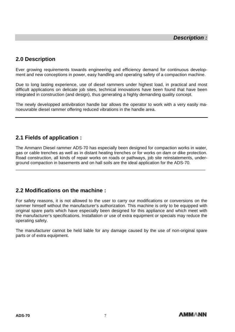
Description : 2.0 Description Ever growing requirements towards engineering and efficiency demand for continuous develop-ment and new conceptions in power, easy handling and operating safety of a compaction machine. Due to long lasting experience, use of diesel rammers under highest load, in practical and most difficult applications on delicate job sites, technical innovations have been found that have been integrated in construction (and design), thus generating a highly demanding quality concept. The newly developped antivibration handle bar allows the operator to work with a very easily ma-noeuvrable diesel rammer offering reduced vibrations in the handle area. 2.1 Fields of application :
The Ammann Diesel rammer ADS-70 has especially been designed for compaction works in water, gas or cable trenches as well as in distant heating trenches or for works on dam or dike protection. Road construction, all kinds of repair works on roads or pathways, job site reinstatements, under-ground compaction in basements and on hall soils are the ideal application for the ADS-70. ________________________________________________________________________________ 2.2 Modifications on the machine :
For safety reasons, it is not allowed to the user to carry our modifications or conversions on the rammer himself without the manufacturer’s authorization. This machine is only to be equipped with original spare parts which have especially been designed for this appliance and which meet with the manufacturer’s specifications. Installation or use of extra equipment or specials may reduce the operating safety. The manufacturer cannot be held liable for any damage caused by the use of non-original spare parts or of extra equipment.

ADS-70 8
ADS-70 9
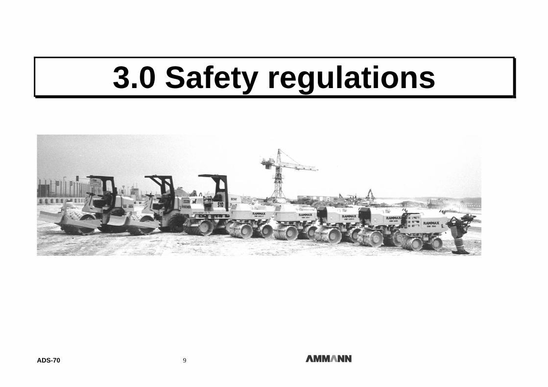
3.0 Safety regulations
ADS-70 10
Safety regulations : 3.1 Proper use :
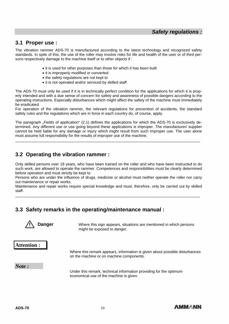
The vibration rammer ADS-70 is manufactured according to the latest technology and recognized safety standards. In spite of this, the use of the roller may involve risks for life and health of the user or of third per-sons respectively damage to the machine itself or to other objects if : • it is used for other purposes than those for which it has been built • it is improperly modified or converted • the safety regulations are not kept to • it is not operated and/or serviced by skilled staff The ADS-70 must only be used if it is in technically perfect condition for the applications for which it is prop-erly intended and with a due sense of concern for safety and awareness of possible dangers according to the operating instructions. Especially disturbances which might affect the safety of the machine must immediately be eradicated. For operation of the vibration rammer, the relevant regulations for prevention of accidents, the standard safety rules and the regulations which are in force in each country do, of course, apply. The paragraph „Fields of application“ (2.1) defines the applications for which the ADS-70 is exclusively de-termined. Any different use or use going beyond these applications is improper. The manufacturer/ supplier cannot be held liable for any damage or injury which might result from such improper use. The user alone must assume full responsibility for the results of improper use of the machine. ______________________________________________________________________________________ 3.2 Operating the vibration rammer : Only skilled persons over 18 years, who have been trained on the roller and who have been instructed to do such work, are allowed to operate the rammer. Competences and responsibilities must be clearly determined before operation and must strictly be kept to. Persons who are under the influence of drugs, medicine or alcohol must neither operate the roller nor carry out maintenance or repair works. Maintenance and repair works require special knowledge and must, therefore, only be carried out by skilled staff. ______________________________________________________________________________________ 3.3 Safety remarks in the operating/maintenance manual :
Danger Where this sign appears, situations are mentioned in which persons might be exposed to danger.
Attention : Where this remark appears, information is given about possible disturbances on the machine or on machine components. Note : Under this remark, technical information providing for the optimum economical use of the machine is given.
ADS-70 11
Safety regulations : 3.4 Warning stickers on the vibration rammer : Safety labels and warning stickers must be kept completely legible and must absolutely be observed.
Damaged and illegible safety labels and warning stickers must immediately be renewed.
All labels and stickers can be ordered according to our spare parts list. 3.5 Loading the vibration rammer : - The rammer must be secured against tipping over or sliding. - On transport vehicles, the rammer must be secured so that it cannot roll down, slide or tip over. There is danger to life for persons who
• step under suspended loads or who stand underneath suspended loads. 3.6 Starting the vibration rammer : 3.6.1 Before start-up : - The rammer must only be operated from the operator’s stand which is always behind the machine.
- Before start-up, the operator must make himself familiar with the equipment, with operating and control elements as well as with the functioning of the machine.
- The operator must make use of his personal protective equipment such as safety helmet, safety boots etc. Before start-up, always check whether :
• there are persons or obstacles beside or underneath the rammer • the rammer is free of oily or inflammable substances • all levers are free of grease, oil, fuel, dirt, snow or ice • the rammer shows any obvious defects • all safety devices are firmly in their place • all operating elements work all right - Do never start the rammer if the control elements are defective. - Do not attach any loose objects to the machine. 3.6.2 Start-up : For starting the rammer, all control levers must be placed in „neutral position“.
Check all indicator and control elements after start-up.

ADS-70 12
Safety regulations : 3.6.3 Start-up in closed rooms :
Exhaust gases are highly dangerous ! When starting the roller in closed rooms, it is, therefore, indispensable to provide for sufficient ventilation. 3.7 Working with the vibration rammer :
3.7.1 Persons in the danger area :
Before starting operation – even after short breaks –, check whether persons or obstacles keep within the danger area.
Give warning signs if necessary. Stop operation immediately if persons do not leave the danger area in spite of the warnings. 3.7.2 Moving the vibration rammer :
- In cases of emergency or danger, the engine must immediately be stopped. Do only start operation again after the danger, due to which operation was stopped, has been removed.
- In case of unusual noise or smoke development, stop the machine, find out the reason and have it removed. 3.7.3 Moving the vibration rammer on slopes :
- Do not work on slopes that are steeper than the rammer’s maximum gradeability provides for. - Work carefully on slopes and always straight up or down in direction. - On humid and loose-packed soils, the rammer’s ground adherence on slopes is reduced considerably. Increased danger of accidents ! 3.7.4 Conduct in traffic :
- Choose speed in accordance with the working conditions. - Do always give priority to loaded transport vehicles. - Keep a safe distance to edges and hill flanks. 3.7.5 Checking the effects of vibration :
When carrying out compaction works with vibration, the effect on nearby buildings and pipes lying in the ground (gas, water, sewerage, current conduction) must be checked and, if necessary, the compaction work must be stopped. Never use vibration on hard ground (concrete or frozen soils); damage could be caused to the bearings ! 3.7.6 Parking the vibration rammer : If possible, park the rammer on even, rigid ground. Before leaving the rammer : • stop the engine.
Secure parking machines which might constitute an obstacle to traffic by conspicuous measures. 3.7.7 Parking the vibration rammer on slopes :
Secure the rammer so that it cannot tip over.

ADS-70 13
Safety regulations : 3.8 Taking in fuel :
• Do not breathe in fuel vapours. • Do only refuel the rammer with the engine stopped.
• Do not refuel the rammer in closed rooms. • No open fire, do not smoke.
• Do not spill fuel; catch fuel running out before it can seep away into the soil.
3.9 Maintenance works :
- Only skilled and trained staff is allowed to carry out maintenance works.
- Keep away unauthorized persons from the machine.
- Do never carry out maintenance works on a driving machine or with the engine running.
- Park the rammer on even and rigid ground.
3.9.1 Working on the engine :
Let engine oil drain off at working temperature. – Danger of scaldings !
Wipe off overflowing oil, catch oil running out and dispose of in an environment-friendly manner.
Keep used filters and other oily material in a separate, especially marked container and dispose of in an envi-ronment-friendly manner. 3.9.2 Cleaning works :
• Never carry out cleaning works with the engine running. • Never use petrol or other easily inflammable substances for cleaning. • When cleaning with the steam jet cleaner, cover all electrical components and the insulation material or do not expose them directly to water or steam jets. • Do not hold the cleaning jet directly onto the sound absorber. 3.9.3 After the maintenance works :
- Install any protective devices again after having carried out cleaning and maintenance works. - Carry out a performance test. 3.10 Repair :
If the rammer is defective, hang a corresponding warning sign on it.
Repair works are only to be carried out by skilled staff having been instructed to do so.

ADS-70 14
ADS-70 15
Operation :
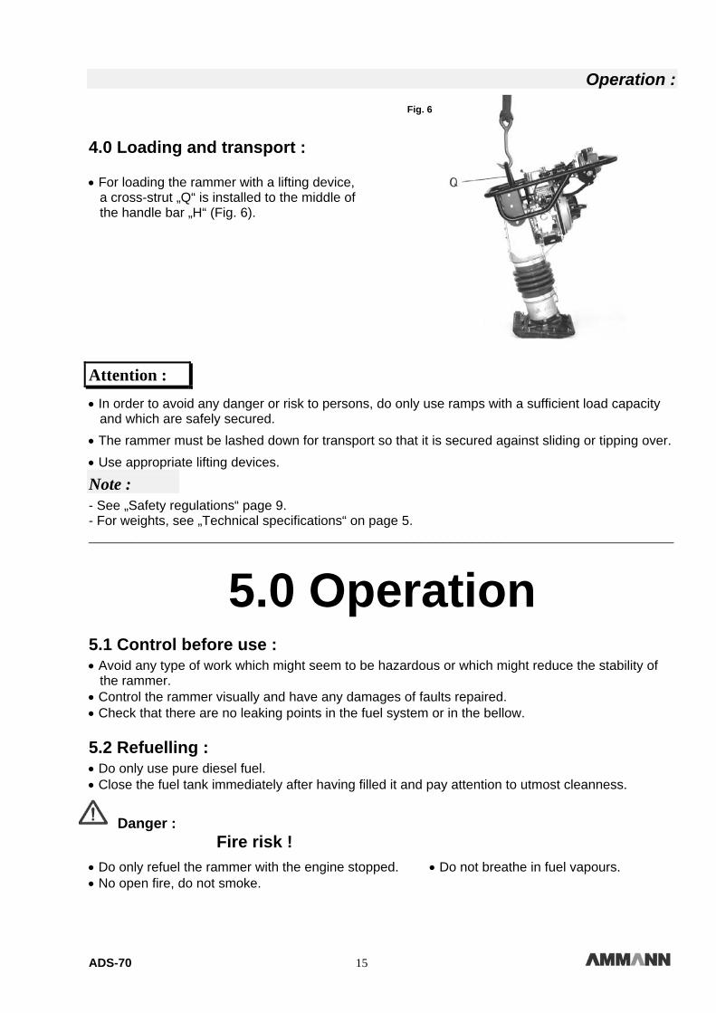
4.0 Loading and transport : • For loading the rammer with a lifting device, a cross-strut „Q“ is installed to the middle of the handle bar „H“ (Fig. 6).
Attention :
• In order to avoid any danger or risk to persons, do only use ramps with a sufficient load capacity and which are safely secured.
• The rammer must be lashed down for transport so that it is secured against sliding or tipping over.
• Use appropriate lifting devices.
Note :
- See „Safety regulations“ page 9. - For weights, see „Technical specifications“ on page 5. _________________________________________________________________________________
5.0 Operation 5.1 Control before use :
• Avoid any type of work which might seem to be hazardous or which might reduce the stability of the rammer. • Control the rammer visually and have any damages of faults repaired. • Check that there are no leaking points in the fuel system or in the bellow. 5.2 Refuelling :
• Do only use pure diesel fuel. • Close the fuel tank immediately after having filled it and pay attention to utmost cleanness.
Danger : Fire risk !
• Do only refuel the rammer with the engine stopped. • Do not breathe in fuel vapours. • No open fire, do not smoke.
Fig. 6
ADS-70 16
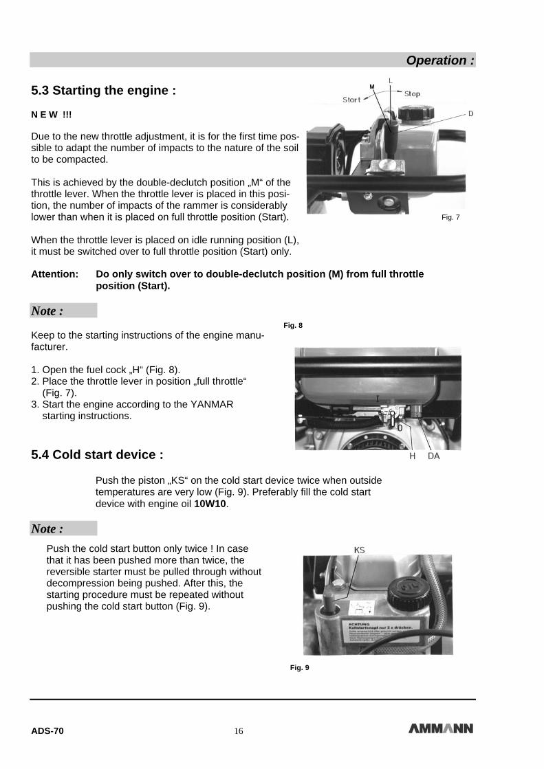
Operation : 5.3 Starting the engine : N E W !!! Due to the new throttle adjustment, it is for the first time pos-sible to adapt the number of impacts to the nature of the soil to be compacted. This is achieved by the double-declutch position „M“ of the throttle lever. When the throttle lever is placed in this posi-tion, the number of impacts of the rammer is considerably lower than when it is placed on full throttle position (Start). When the throttle lever is placed on idle running position (L), it must be switched over to full throttle position (Start) only. Attention: Do only switch over to double-declutch position (M) from full throttle
position (Start). Note : Keep to the starting instructions of the engine manu-facturer. 1. Open the fuel cock „H“ (Fig. 8). 2. Place the throttle lever in position „full throttle“ (Fig. 7). 3. Start the engine according to the YANMAR starting instructions. 5.4 Cold start device :
Push the piston „KS“ on the cold start device twice when outside temperatures are very low (Fig. 9). Preferably fill the cold start device with engine oil 10W10.
Note :
Fig. 9
Fig. 7
Fig. 8
Push the cold start button only twice ! In case that it has been pushed more than twice, the reversible starter must be pulled through without decompression being pushed. After this, the starting procedure must be repeated without pushing the cold start button (Fig. 9).
Fig. 7

ADS-70 17
Operation : 5.5 Working with the vibration rammer :
• Avoid the rammer vibrating while its butt plate is not touching ground. • Never lift the rammer during operation ! Note : - The moving speed can be regulated over the rammer’s inclination.
Inclination forwards = fast movement forwards
Inclination backwards = slow movement forwards - The moving speed can as well be regulated over the pressure exerted on the handle bar. ______________________________________________________________________________ 5.6 Adjustment during breaks : • Place the throttle lever in position „idle running“ (L; Fig. 7).
Attention :
Never leave the rammer unsupervised during working breaks ! 5.7 Stopping the engine : • Place the throttle lever „G“ to „Stop“-position and the engine will stop (Fig. 7). • Close the fuel cock by turning it in position „0“ (Fig. 8). ______________________________________________________________________________
6.0 Recommendation for compaction works with ADS 70 The maximum layer height depends on several factors : 1. nature of the ground 2. humidity 3. grain distribution in the ground 4. grain size For this reason, it is not possible to give exact details regarding the maximum layer height. Recommendation : Determine the maximum layer height in each single case by tests and by taking samples of the soil !

ADS-70 18
Maintenance :
7.0 Maintenance 7.1 General remarks on maintenance and maintenance work : Strictly keep to all safety regulations when carrying out maintenance works ! Careful maintenance guarantees a much better functioning safety of the roller and prolongs the life of all important components. The time and work required for this purpose are out of all proportion to any disturbances that might occur due to non-observance. • Engine and machine must be thoroughly cleaned before any maintenance work is carried out. • The engine must be inactive during all maintenance work. • Do only carry out maintenance and repair work with the machine standing on even, rigid ground and being secured against rolling away. • Ensure that any maintenance and inspection work provided for and described in the operating instruction is observed and carried out, including instructions on replacement of parts. Such work must only be done by skilled and qualified staff. • During maintenance works, neither oil nor fuel must get into ground or drains. These must be caught up in suitable containers and disposed off in an environment-friendly manner ! _______________________________________________________________________________ 7.2 Instructions for running-in : Maintenance after 25 operating hours :
• Check all screw connections and tighten where necessary. • Change the diesel filter (page 19, paragraph 7.5). • Engine : See maintenance instructions for YANMAR L 40 AE ! _________________________________________________________________________________
7.3 Diesel engine :
See operating instructions YANMAR L 40 AE.
Danger : You can get seriously burned by hot engine components !
_________________________________________________________________________________
ADS-70 19
Maintenance : 7.4 Changing the oil in the tamping system :
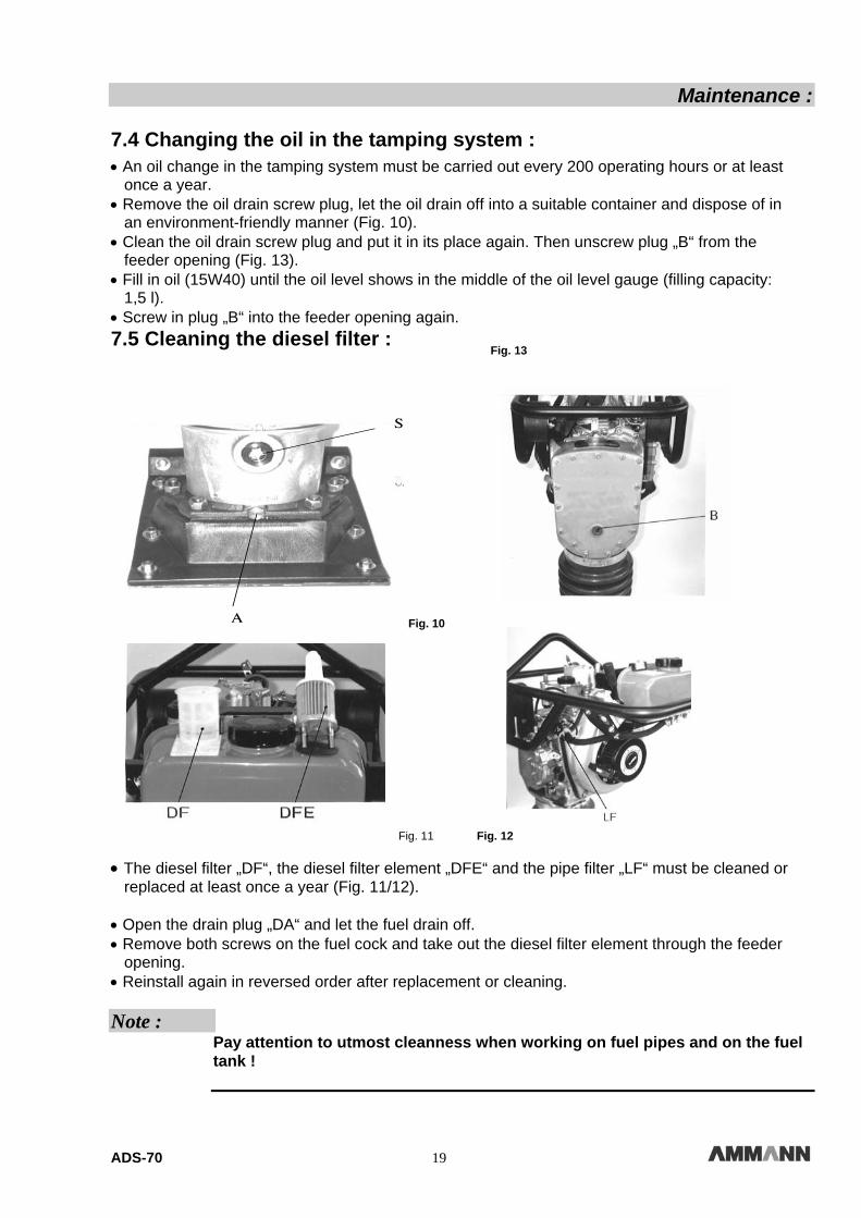
• An oil change in the tamping system must be carried out every 200 operating hours or at least once a year. • Remove the oil drain screw plug, let the oil drain off into a suitable container and dispose of in an environment-friendly manner (Fig. 10). • Clean the oil drain screw plug and put it in its place again. Then unscrew plug „B“ from the feeder opening (Fig. 13). • Fill in oil (15W40) until the oil level shows in the middle of the oil level gauge (filling capacity: 1,5 l). • Screw in plug „B“ into the feeder opening again. 7.5 Cleaning the diesel filter :
Fig. 11 Fig. 12
• The diesel filter „DF“, the diesel filter element „DFE“ and the pipe filter „LF“ must be cleaned or replaced at least once a year (Fig. 11/12). • Open the drain plug „DA“ and let the fuel drain off. • Remove both screws on the fuel cock and take out the diesel filter element through the feeder opening. • Reinstall again in reversed order after replacement or cleaning. Note :
Pay attention to utmost cleanness when working on fuel pipes and on the fuel tank !
Fig. 10
Fig. 13
ADS-70 20
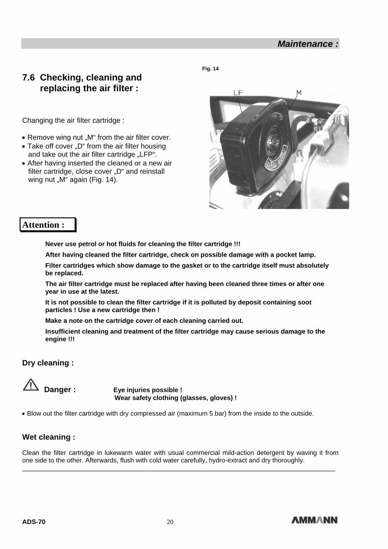
Maintenance : 7.6 Checking, cleaning and replacing the air filter : Changing the air filter cartridge : • Remove wing nut „M“ from the air filter cover. • Take off cover „D“ from the air filter housing and take out the air filter cartridge „LFP“. • After having inserted the cleaned or a new air filter cartridge, close cover „D“ and reinstall wing nut „M“ again (Fig. 14).
Attention : Never use petrol or hot fluids for cleaning the filter cartridge !!!
After having cleaned the filter cartridge, check on possible damage with a pocket lamp.
Filter cartridges which show damage to the gasket or to the cartridge itself must absolutely be replaced.
The air filter cartridge must be replaced after having been cleaned three times or after one year in use at the latest.
It is not possible to clean the filter cartridge if it is polluted by deposit containing soot particles ! Use a new cartridge then !
Make a note on the cartridge cover of each cleaning carried out.
Insufficient cleaning and treatment of the filter cartridge may cause serious damage to the engine !!! Dry cleaning :
Danger : Eye injuries possible ! Wear safety clothing (glasses, gloves) ! • Blow out the filter cartridge with dry compressed air (maximum 5 bar) from the inside to the outside. Wet cleaning : Clean the filter cartridge in lukewarm water with usual commercial mild-action detergent by waving it from one side to the other. Afterwards, flush with cold water carefully, hydro-extract and dry thoroughly. ______________________________________________________________________________________
Fig. 14

ADS-70 21
Maintenance :
8.0 Screw torques for screws with metric threads
Screw Dimensions
Torques Nm
8.8 10.9 12.9 M4 3 5 5 M5 6 9 10 M6 10 15 18 M8 25 35 45 M10 50 75 83 M12 88 123 147 M14 137 196 235 M16 211 300 358 M18 290 412 490 M20 412 578 696 M22 560 785 942 M24 711 1000 1200 M27 1050 1480 1774 M30 1420 2010 2400
Screw dimensions
Torques ft-lb
8.8 10.9 12.9 M4 2 3 4 M5 4 7 7 M6 7 11 13 M8 18 26 33 M10 37 55 61 M12 65 91 108 M14 101 145 173 M16 156 221 264 M18 213 303 361 M20 304 426 513 M22 413 559 695 M24 524 798 885 M27 774 1092 1308 M30 1047 1482 1770
Property classes for screws with non treated, non greased surface. The screw’s quality marks appear on the screw heads. 8.8 = 8G; 10.9 = 10K; 12.9 = 12K The values give a 90 % utilization of the screw’s apparent yielding point at a coefficient of friction of μ total = 0,14. Observance of the screw torques is controlled by torquemeter. When lubricant MoSo2 is used, the indicated screw torques do not apply. Note : Always renew self-locking nuts after disassembly !
ADS-70 22
Maintenance :
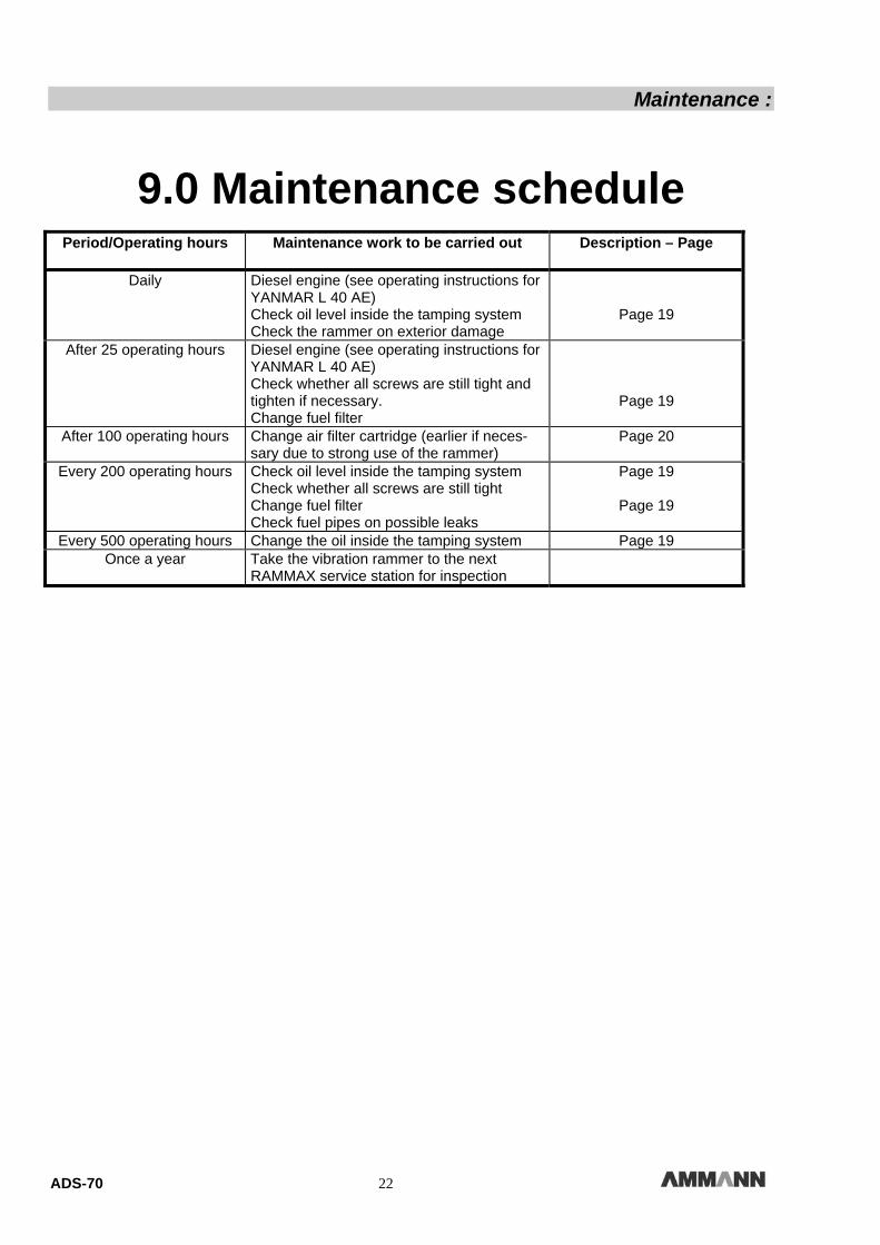
9.0 Maintenance schedule
Period/Operating hours
Maintenance work to be carried out Description – Page
Daily Diesel engine (see operating instructions for YANMAR L 40 AE) Check oil level inside the tamping system Check the rammer on exterior damage
Page 19
After 25 operating hours Diesel engine (see operating instructions for YANMAR L 40 AE) Check whether all screws are still tight and tighten if necessary. Change fuel filter
Page 19
After 100 operating hours Change air filter cartridge (earlier if neces-sary due to strong use of the rammer)
Page 20
Every 200 operating hours Check oil level inside the tamping system Check whether all screws are still tight Change fuel filter Check fuel pipes on possible leaks
Page 19
Page 19
Every 500 operating hours Change the oil inside the tamping system Page 19 Once a year Take the vibration rammer to the next
RAMMAX service station for inspection