OPTIMIZING LEGGED LOCOMOTION USING TUNABLE … · OPTIMIZING LEGGED LOCOMOTION USING TUNABLE LEG...
29
With support of NSF Award no. EEC-0754741 OPTIMIZING LEGGED LOCOMOTION USING TUNABLE LEG STIFFNESS NSF Summer Undergraduate Fellowship in Sensor Technologies Kamruzzaman Rony (Electrical Engineering) – Stony Brook University Advisors: Dr. Dan Koditschek and Kevin Galloway ABSTRACT Running efficiently and successfully over unstructured terrain is an important and necessary characteristic for modern legged robots. Research suggests that a necessary step toward achieving this goal is to design legged robots with variable leg stiffness capabilities which can be controlled by the robot autonomously. The specific problem addressed in this research is to develop a wireless (infrared) tunable leg stiffness module that will change leg stiffness when commanded by the robot. In this research, a legged robot with six C-shape legs called RHex is used. The development of the tunable leg stiffness module had two phases. The first phase focused on the design of an infrared communication module that would allow each leg to communicate with the robot body. The second phase involved the integration of a motor and rotary sensor to accurately control stiffness of the leg based commands from robot. In this paper, we discuss the development of this novel tunable robot leg and highlight its advantages and limitations for optimizing RHex-like legged locomotion platforms.
Transcript of OPTIMIZING LEGGED LOCOMOTION USING TUNABLE … · OPTIMIZING LEGGED LOCOMOTION USING TUNABLE LEG...
With support of NSF Award no. EEC-0754741
OPTIMIZING LEGGED LOCOMOTION USING TUNABLE LEG STIFFNESS
NSF Summer Undergraduate Fellowship in Sensor Technologies
Kamruzzaman Rony (Electrical Engineering) – Stony Brook University Advisors: Dr. Dan Koditschek and Kevin Galloway
ABSTRACT Running efficiently and successfully over unstructured terrain is an important and necessary characteristic for modern legged robots. Research suggests that a necessary step toward achieving this goal is to design legged robots with variable leg stiffness capabilities which can be controlled by the robot autonomously. The specific problem addressed in this research is to develop a wireless (infrared) tunable leg stiffness module that will change leg stiffness when commanded by the robot. In this research, a legged robot with six C-shape legs called RHex is used. The development of the tunable leg stiffness module had two phases. The first phase focused on the design of an infrared communication module that would allow each leg to communicate with the robot body. The second phase involved the integration of a motor and rotary sensor to accurately control stiffness of the leg based commands from robot. In this paper, we discuss the development of this novel tunable robot leg and highlight its advantages and limitations for optimizing RHex-like legged locomotion platforms.
2
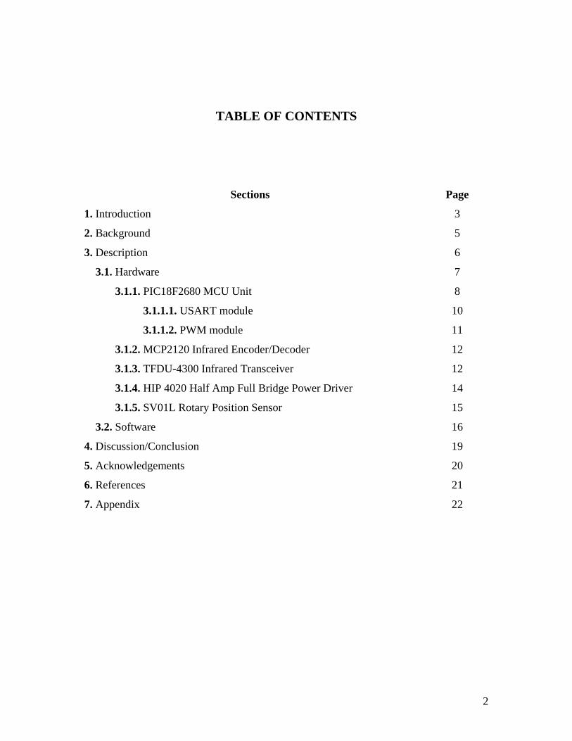
TABLE OF CONTENTS
Sections Page
1. Introduction 3
2. Background 5
3. Description 6
3.1. Hardware 7
3.1.1. PIC18F2680 MCU Unit 8
3.1.1.1. USART module 10
3.1.1.2. PWM module 11
3.1.2. MCP2120 Infrared Encoder/Decoder 12
3.1.3. TFDU-4300 Infrared Transceiver 12
3.1.4. HIP 4020 Half Amp Full Bridge Power Driver 14
3.1.5. SV01L Rotary Position Sensor 15
3.2. Software 16
4. Discussion/Conclusion 19
5. Acknowledgements 20
6. References 21
7. Appendix 22
3
1. INTRODUCTION
Animals or biological systems are capable of moving or running in dynamic fashion over realistic terrain (that varies in geometry, with rises and dips, and in dynamic properties, such as ground stiffness or damping) by varying the stiffness of their limbs in real times to adapt to the changes in the environment [1]. According to the researchers, adjustable leg stiffness is necessary to close the performance gap between robots and animals [1]. Therefore, designing a robot that can autonomously traverse a variety of terrain types requires dynamic stiffness control in its legs.
RHex, a six-legged robot, is one of the most successful autonomous running robots to date. It is the first autonomous dynamic legged locomotion system to passively exchange spring energy through natural body dynamics [2]. It is also the fastest autonomous legged robot capable of operating on rough terrain [3]. Its leg design resembles that of a cockroach and can be explained using the SLIP (Spring Loaded Inverted Pendulum) model. This model treats an animal as a point mass on a linear spring and has been demonstrated to accurately model the center of mass motion of running animals, as well as the ground reaction forces associated with their gaits.
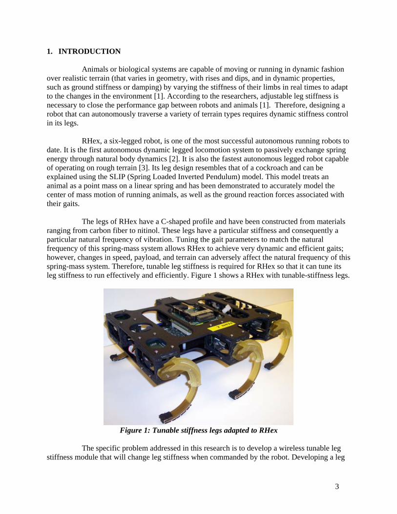
The legs of RHex have a C-shaped profile and have been constructed from materials ranging from carbon fiber to nitinol. These legs have a particular stiffness and consequently a particular natural frequency of vibration. Tuning the gait parameters to match the natural frequency of this spring-mass system allows RHex to achieve very dynamic and efficient gaits; however, changes in speed, payload, and terrain can adversely affect the natural frequency of this spring-mass system. Therefore, tunable leg stiffness is required for RHex so that it can tune its leg stiffness to run effectively and efficiently. Figure 1 shows a RHex with tunable-stiffness legs.
Figure 1: Tunable stiffness legs adapted to RHex
The specific problem addressed in this research is to develop a wireless tunable leg
stiffness module that will change leg stiffness when commanded by the robot. Developing a leg
4
stiffness module consists of two parts. One part is to design a communication module so that the body and the leg can communicate with each other. To address the issue of communication between the robot and the leg, we have selected an infrared device (IrDA transceiver) that comes with a transmitter and receiver. Both the leg and the body have IrDA transceivers, IrDA encoders/decoders and microcontrollers. The IrDA device is inexpensive, robust and is used widely in industry. Wired connection was not a good option for this problem because the legs rotate continuously and slip-rings are too expensive and unsuitable for dirty environments. The second part is to control a motor that changes a slider’s position based on the data provided by the body so that the leg can achieve a particular stiffness (Figure 2).
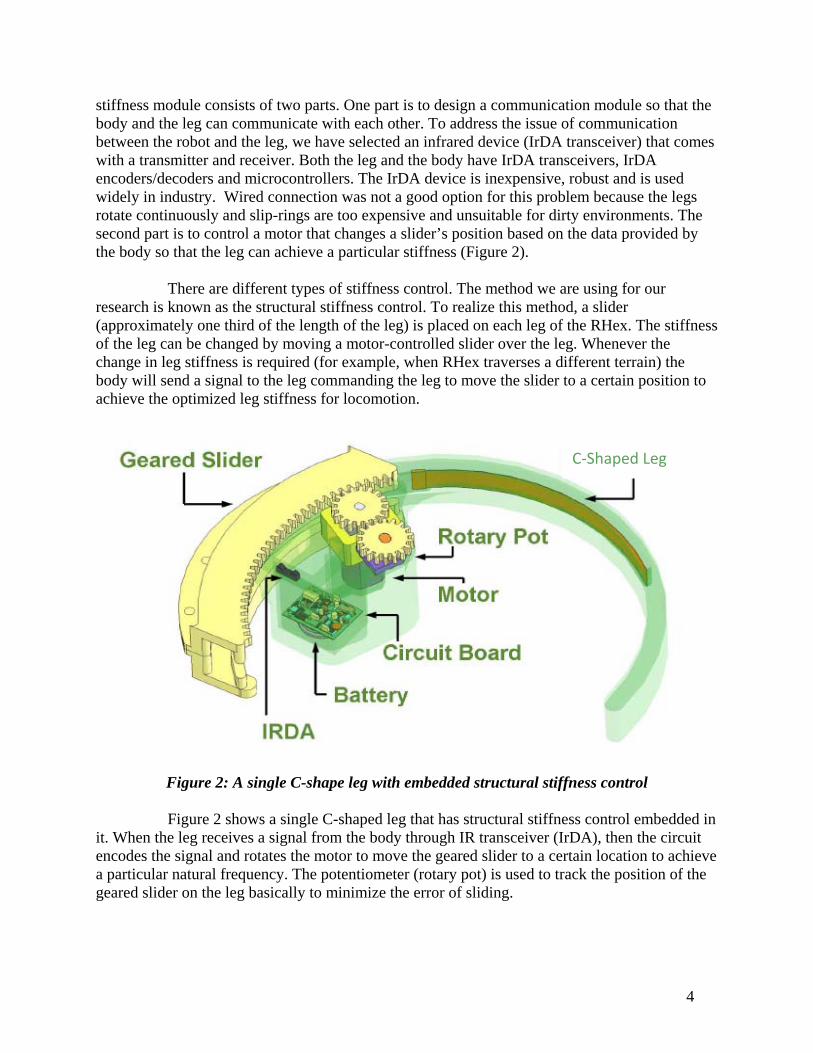
There are different types of stiffness control. The method we are using for our research is known as the structural stiffness control. To realize this method, a slider (approximately one third of the length of the leg) is placed on each leg of the RHex. The stiffness of the leg can be changed by moving a motor-controlled slider over the leg. Whenever the change in leg stiffness is required (for example, when RHex traverses a different terrain) the body will send a signal to the leg commanding the leg to move the slider to a certain position to achieve the optimized leg stiffness for locomotion.
Figure 2: A single C-shape leg with embedded structural stiffness control
Figure 2 shows a single C-shaped leg that has structural stiffness control embedded in it. When the leg receives a signal from the body through IR transceiver (IrDA), then the circuit encodes the signal and rotates the motor to move the geared slider to a certain location to achieve a particular natural frequency. The potentiometer (rotary pot) is used to track the position of the geared slider on the leg basically to minimize the error of sliding.
C‐Shaped Leg
5
2. BACKGROUND
The dynamic legged locomotion in animals is very complex; therefore, it is very difficult to implement it in robots. One practical and feasible way for implementing dynamic legged locomotion in robots is to use a simple mathematical model that almost exactly resembles the legged locomotion of animals. The Spring- Loaded Inverted Pendulum (SLIP) model for animal running is one such model that has successfully approximated the sagittal plane dynamics and ground reaction forces of animals ranging from cockroaches to kangaroos [4]. This model has been applied to RHex’s forward motion. Spring- Loaded Inverted Pendulum (SLIP) model:
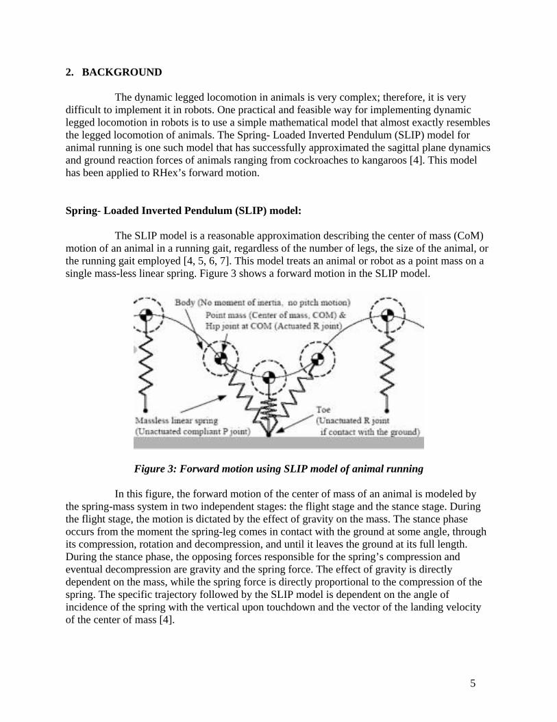
The SLIP model is a reasonable approximation describing the center of mass (CoM) motion of an animal in a running gait, regardless of the number of legs, the size of the animal, or the running gait employed [4, 5, 6, 7]. This model treats an animal or robot as a point mass on a single mass-less linear spring. Figure 3 shows a forward motion in the SLIP model.
Figure 3: Forward motion using SLIP model of animal running
In this figure, the forward motion of the center of mass of an animal is modeled by the spring-mass system in two independent stages: the flight stage and the stance stage. During the flight stage, the motion is dictated by the effect of gravity on the mass. The stance phase occurs from the moment the spring-leg comes in contact with the ground at some angle, through its compression, rotation and decompression, and until it leaves the ground at its full length. During the stance phase, the opposing forces responsible for the spring’s compression and eventual decompression are gravity and the spring force. The effect of gravity is directly dependent on the mass, while the spring force is directly proportional to the compression of the spring. The specific trajectory followed by the SLIP model is dependent on the angle of incidence of the spring with the vertical upon touchdown and the vector of the landing velocity of the center of mass [4].
6
It may seem that the model in figure 3 is only applicable to a monopod. However, this model accurately describes bipedal, quadruped, and hexapod dynamics with the introduction of Sutherland’s virtual leg [8]. Virtual leg describes the idea that legs whose motion is synchronized can be modeled as a single leg. In a hexapod, the three legs comprising a single tripod are synchronized, resulting in two virtual legs. Similarly, quadrupeds can be treated as bipeds. Since the two virtual legs are never both in stance, we are justified in treating them as we would those of a bounding monopod [9]. Given that RHex is largely biologically inspired, the SLIP model of motion is a valid candidate to capture the dynamics of its center of mass, with the stiffness of the three legs of a tripod determining the spring constant of the single linear spring that represents the virtual leg in the model. 3. Description:
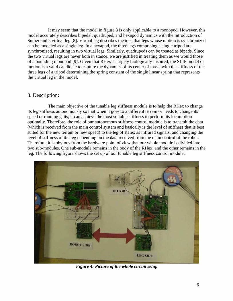
The main objective of the tunable leg stiffness module is to help the RHex to change its leg stiffness autonomously so that when it goes to a different terrain or needs to change its speed or running gaits, it can achieve the most suitable stiffness to perform its locomotion optimally. Therefore, the role of our autonomous stiffness control module is to transmit the data (which is received from the main control system and basically is the level of stiffness that is best suited for the new terrain or new speed) to the leg of RHex as infrared signals, and changing the level of stiffness of the leg depending on the data received from the main control of the robot. Therefore, it is obvious from the hardware point of view that our whole module is divided into two sub-modules. One sub-module remains in the body of the RHex, and the other remains in the leg. The following figure shows the set up of our tunable leg stiffness control module:
Figure 4: Picture of the whole circuit setup
7
In the above figure, the left part is the body sub-module and the right part is the leg sub-module. The small green boards at the bottom are the infrared communication units. The transparent device, on the bottom right corner with two gearings on top, is actually the testing equipment that imitates the function of a leg with slider. The motor and the potentiometer are attached with this device and connected to our main circuitry.
The tunable leg stiffness module that we have developed consists of both the hardware and the software. The functions and details of both the hardware and the software parts and their components are briefly described in the following sections. 3.1 Hardware:
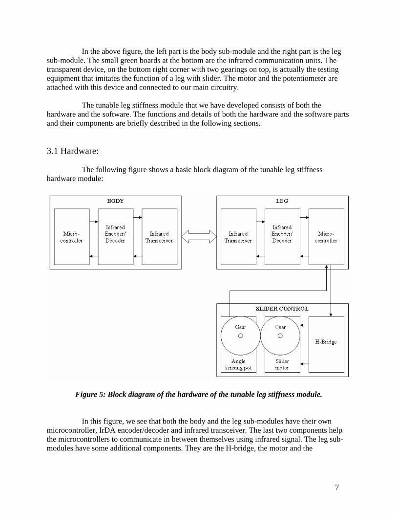
The following figure shows a basic block diagram of the tunable leg stiffness hardware module:
Figure 5: Block diagram of the hardware of the tunable leg stiffness module.
In this figure, we see that both the body and the leg sub-modules have their own
microcontroller, IrDA encoder/decoder and infrared transceiver. The last two components help the microcontrollers to communicate in between themselves using infrared signal. The leg sub-modules have some additional components. They are the H-bridge, the motor and the
8
potentiometer. These components are required to place the slider to a certain position on the leg to achieve particular leg stiffness.
The functions of the different components of our module are described here. The microcontroller in the body part gets the data from the main microcontroller of the RHex through wired connection. Then the body-microcontroller sends the data to the infrared encoder/decoder, which after encoding sends the encoded data to the infrared transceiver. The Infrared transceiver transmits infrared signals which are received by the infrared transceiver in the leg. The infrared encoder/decoder connected to the infrared transceiver in the leg part decodes the infrared signal and send the data to the microcontroller connected to it. Depending on the received data, the microcontroller controls the H-bridge which actually controls the motor’s rotation and the direction of rotation. The motor gear is in contact with another gear which is tied to an angle sensing potentiometer. Therefore, when the motor rotates, the voltage at the variable node of the potentiometer also changes. By measuring the voltage of the potentiometer, we can tell the position of the motor or the slider on the leg. Since the voltage of the potentiometer is analog, it indicates infinite number of position. However, for our application we need to deal with definite number of positions. For this reason we have used an analog-to-digital converter (ADC). The microcontroller we are using has a 10 bit ADC as its peripheral and we have used that. Beside the 10 bit ADC, we have also used other two peripherals of the microcontroller. They are the universal synchronous asynchronous receiver transmitter (USART) and the pulse width modulation (PWM) peripherals. We have used USART for infrared communication and PWM to control the driving power (or the speed of rotation) of the motor.
The microcontrollers that we have used for both sub-modules are the same and they are PIC18F2680. The model numbers for infrared encoder/decoders, transceivers, H-bridge and potentiometer are respectively MCP2120, TFDU-4300, HIP4020 and SV01L. Brief descriptions of these components along with their mentionable features are described in the following sections. 3.1.1 PIC18F2680 Microcontroller Unit (MCU):
PIC18F2680 is a 28 pin enhanced flash microcontrollers with ECAN™ technology, 10-Bit A/D converter and nano-watt Technology. Its maximum DC operating frequency is 40 MHz. Its main features are as follows:
o 65536 bytes of program memory. o 3328 bytes of data memory. o 1024 bytes of data EEPROM memory. o Total 19 interrupt sources o Three 8-bits I/O ports – port A, B and C. o Four timers. o One capture/compare/PWM module. o 10 different oscillator modes with one 8 MHz internal oscillator. o MSSP and Enhanced USART for serial communication. o 10 bit A/D converter with 8 input channels. o Programmable High/Low voltage detects option.
9
o 75 instructions with general instruction set enabled and 83 instructions with extended instruction set enabled.
These are the main features that are used for the development of our module.
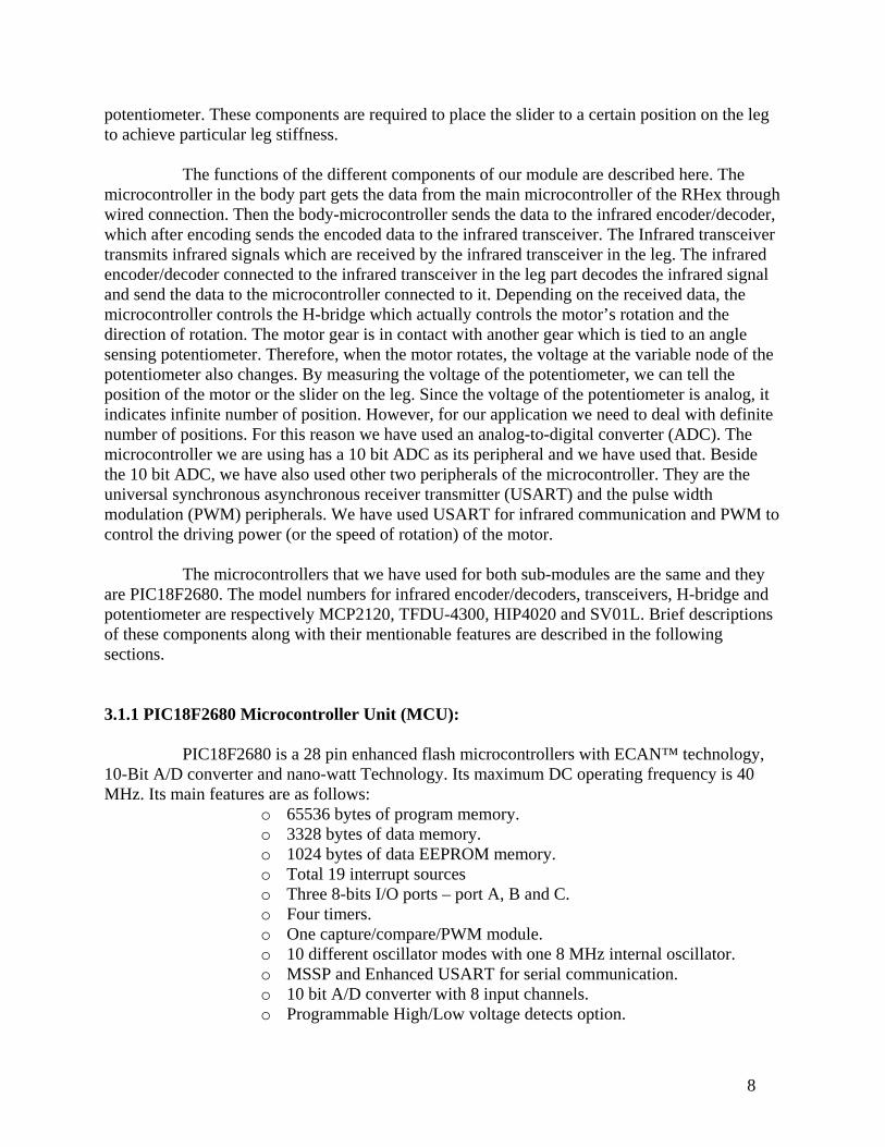
However, this MCU offers many other important features that can be utilized to develop a high-end embedded system. The pin configuration of this MCU is shown in Figure 2.
Figure 6: Pin diagram of PIC18F2680 PDIP
In our design, we are using internal 8 MHz oscillator for both the body and the leg
sub modules. For the MCU in the body sub-module the pins that we have used are pin 2, 3, 4, 5, 8, 17, 18, 19 and 20. Among them, pin 20 is connected to VDD (+5V), pin 8 and 19 are connected to GND. Pin 2, 3, 4, 5 are connected to switch and are the input to the module. Among these four pins, pin 2, 3, 4 determines the position of the slider on the leg and pin 5 determines the direction of rotation of the pin. Since we are using 3 pins to determine the position of the slider, so the slider can be placed to 2^3 = 8 different position, which is good enough for our present research. If more positions are needed then we can use more pins to indicate the position. Pin 17 (TX) and 18 (RX) are used for the serial data transmission using USART to implement infrared communication scheme. These two pins are connected respectively to pin 12 (TX) and 11 (RX) of the infrared encoder/decoder of the body sub-module.
On the other hand, for the MCU in the leg sub-module the pins that we have used are pin 2, 3, 4, 5, 8, 13, 17, 18, 19 and 20. Among these pins, pin 20 is connected to VDD (+5V), pin 8 and 19 is connected to GND. Pin 17 (TX) and 18 (RX) are used to implement the infrared communication scheme and they are respectively connected to pin 12 (TX) and 11 (RX) of the infrared encoder/decoder of the leg sub-module. Pin 13 (CCP1) and pin 3 are respectively connected to pin 10 and pin 9 of the H-bridge. Pin 13 provides the pulse width modulated signal to the H-bridge and eventually to the motor. Pin 3 controls the direction of rotation of the motors. The data at pin 3 is the same data that is entered at pin 5 of the body module. Pin 4 (Vref-) and 5 (Vref+) are connected to the GND and VDD pins of the angle sensing potentiometer respectively. Pin 2 is configured as an analog input for the 10 bit A/D converter and is connected to the variable voltage pin of the potentiometer.
10
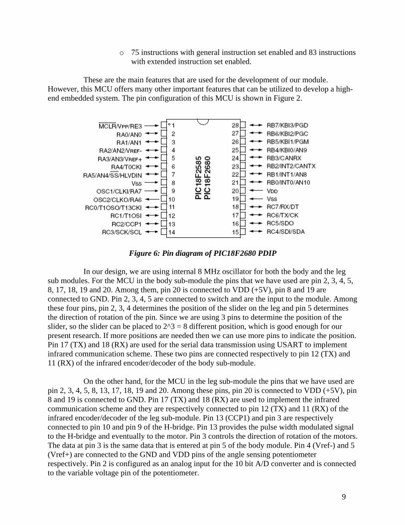
The following table describes the position of the slider depending on the inputs (pin
2, 3, 4 and 5) at the MCU of body sub-module.
Table 1: Position of the slider depending on the input at the body sub-module INPUT POSITION (Angle – only for testing)
PIN 2 PIN 3 PIN 4 PIN 5 = 0 (Clockwise)
PIN 5 = 1 (Anticlockwise)
0 0 0 1 (0o) 1 (0o) 0 0 1 2 (45o) 2 (45o) 0 1 0 3 (90o) 3 (90o) 0 1 1 4 (135o) 4 (135o) 1 0 0 5 (180o) 5 (180o) 1 0 1 6 (225o) 6 (225o) 1 1 0 7 (270o) 7 (270o) 1 1 1 8 (315o) 8 (315o)
The following sections provide brief overviews and configurations of different
peripherals of the MCU that are used in our design. These peripherals are the USART module, PWM module and 10 bit A/D Converter module. 3.1.1.1 USART module:
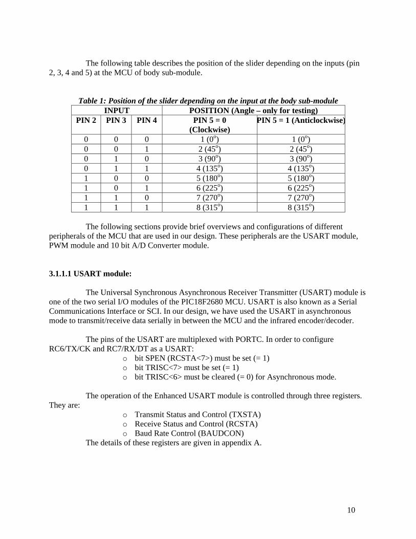
The Universal Synchronous Asynchronous Receiver Transmitter (USART) module is one of the two serial I/O modules of the PIC18F2680 MCU. USART is also known as a Serial Communications Interface or SCI. In our design, we have used the USART in asynchronous mode to transmit/receive data serially in between the MCU and the infrared encoder/decoder.
The pins of the USART are multiplexed with PORTC. In order to configure RC6/TX/CK and RC7/RX/DT as a USART:
o bit SPEN (RCSTA<7>) must be set (= 1) o bit TRISC<7> must be set (= 1) o bit TRISC<6> must be cleared (= 0) for Asynchronous mode.
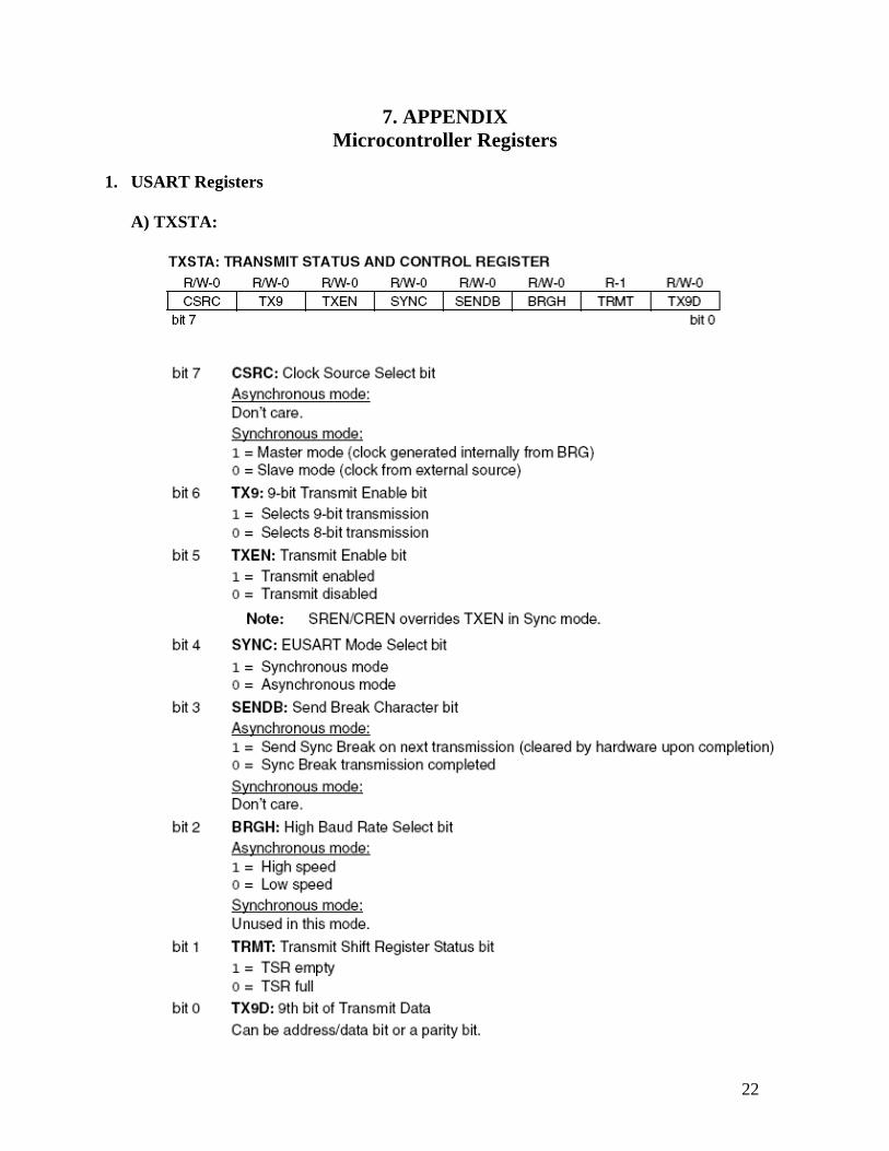
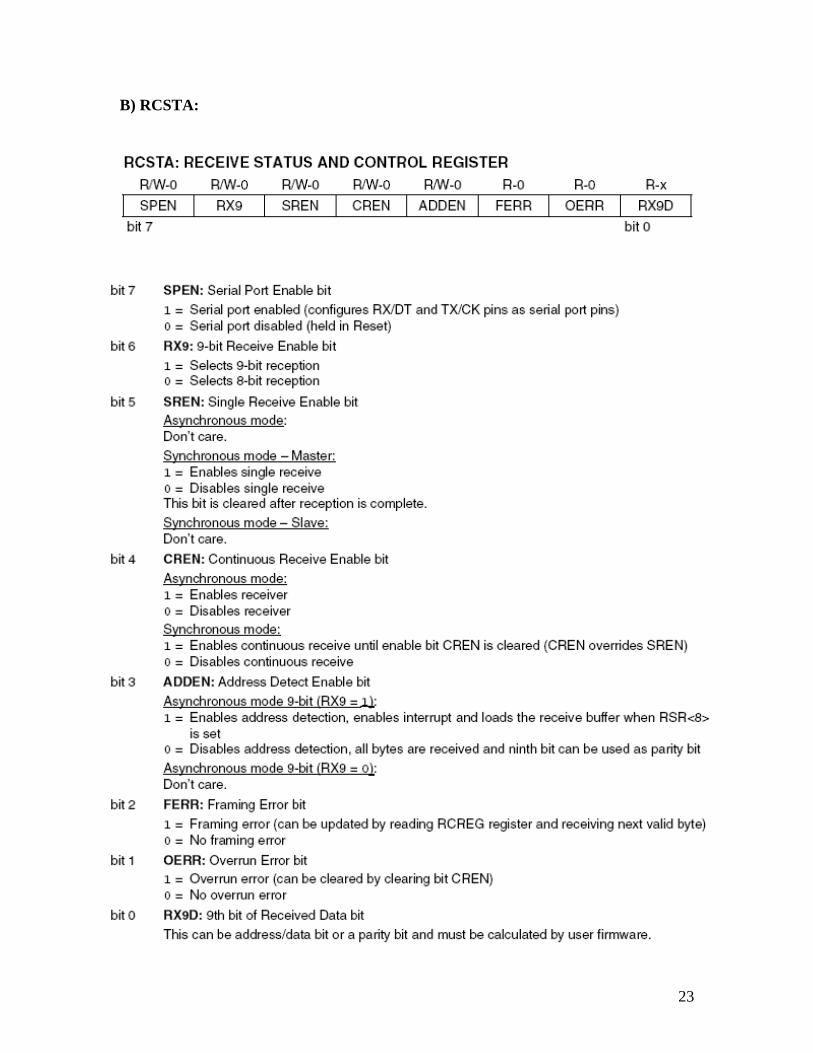
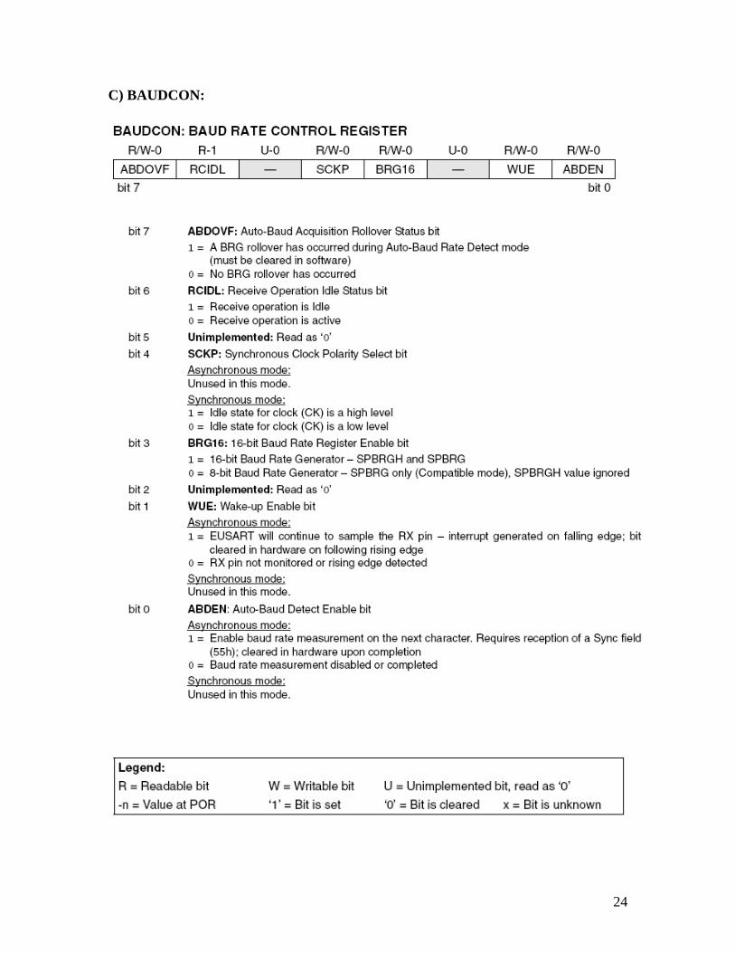
The operation of the Enhanced USART module is controlled through three registers.
They are: o Transmit Status and Control (TXSTA) o Receive Status and Control (RCSTA) o Baud Rate Control (BAUDCON)
The details of these registers are given in appendix A.
11
3.1.1.2 PWM module:
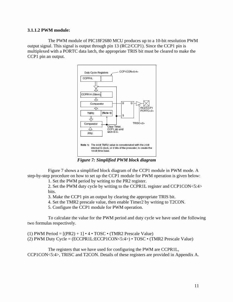
The PWM module of PIC18F2680 MCU produces up to a 10-bit resolution PWM output signal. This signal is output through pin 13 (RC2/CCP1). Since the CCP1 pin is multiplexed with a PORTC data latch, the appropriate TRIS bit must be cleared to make the CCP1 pin an output.
Figure 7: Simplified PWM block diagram
Figure 7 shows a simplified block diagram of the CCP1 module in PWM mode. A
step-by-step procedure on how to set up the CCP1 module for PWM operation is given below: 1. Set the PWM period by writing to the PR2 register. 2. Set the PWM duty cycle by writing to the CCPR1L register and CCP1CON<5:4> bits. 3. Make the CCP1 pin an output by clearing the appropriate TRIS bit. 4. Set the TMR2 prescale value, then enable Timer2 by writing to T2CON. 5. Configure the CCP1 module for PWM operation.
To calculate the value for the PWM period and duty cycle we have used the following
two formulas respectively.
(1) PWM Period = [(PR2) + 1] • 4 • TOSC • (TMR2 Prescale Value) (2) PWM Duty Cycle = (ECCPR1L:ECCP1CON<5:4>) • TOSC • (TMR2 Prescale Value)
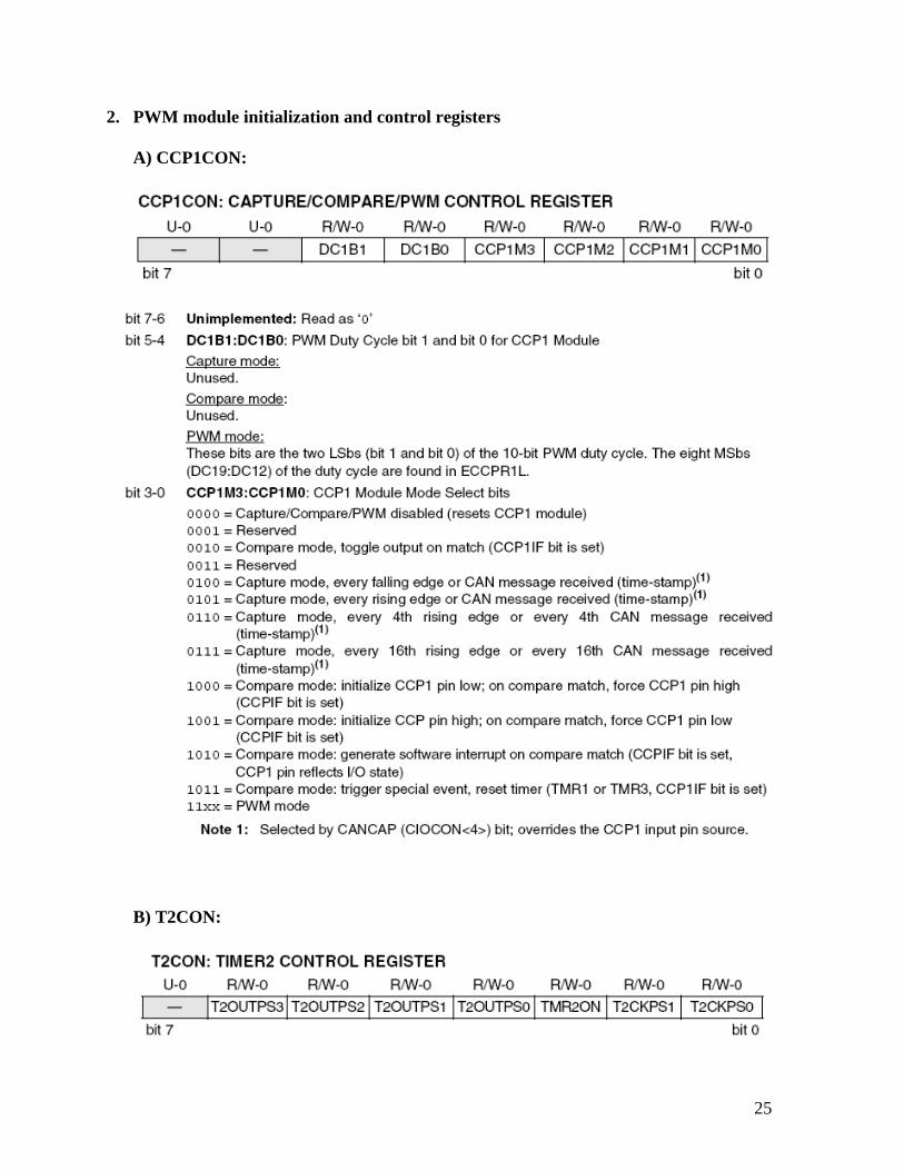
The registers that we have used for configuring the PWM are CCPR1L, CCP1CON<5:4>, TRISC and T2CON. Details of these registers are provided in Appendix A.

12
3.1.1.3 10 bit A/D Converter module:
The Analog-to-Digital (A/D) converter module has 8 inputs and it allows the conversion of an analog input signal to a corresponding 10-bit digital number. This module has five registers:
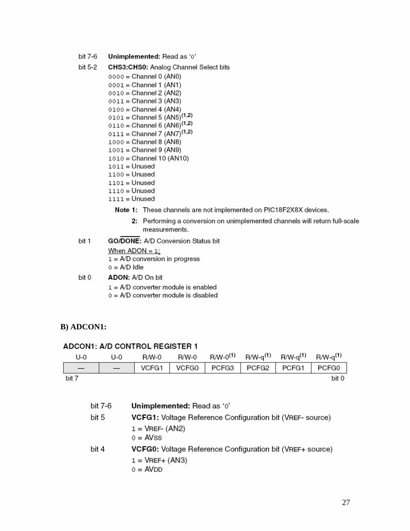
o A/D Result High Register (ADRESH) o A/D Result Low Register (ADRESL) o A/D Control Register 0 (ADCON0) o A/D Control Register 1 (ADCON1) o A/D Control Register 2 (ADCON2)
The ADCON0 register controls the operation of the A/D module. The ADCON1
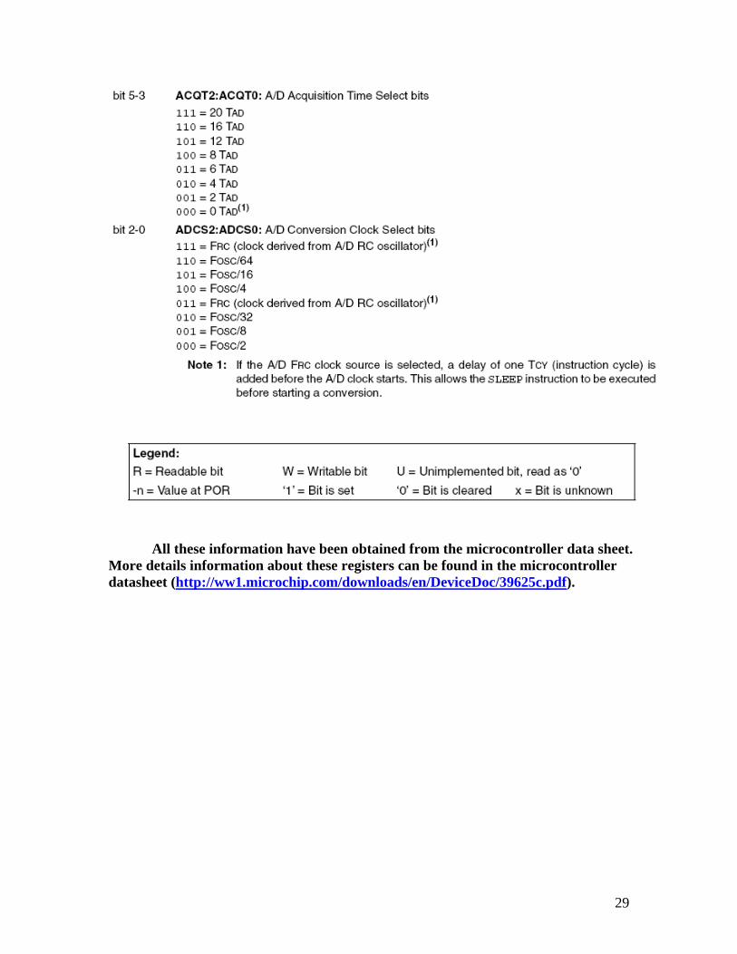
register configures the functions of the port pins. The ADCON2 register configures the A/D clock source, programmed acquisition time and justification. Details of these registers are provided in Appendix A. The following steps should be followed to perform an A/D conversion:
1. Configure the A/D module: o Configure analog pins, voltage reference and o digital I/O (ADCON1) o Select A/D input channel (ADCON0) o Select A/D acquisition time (ADCON2) o Select A/D conversion clock (ADCON2) o Turn on A/D module (ADCON0)
2. Wait the required acquisition time (if required). 3. Start conversion:
o Set GO/DONE bit (ADCON0 register) 4. Wait for A/D conversion to complete, by either:
o Polling for the GO/DONE bit to be cleared or o Waiting for the A/D interrupt
5. Read A/D Result registers (ADRESH:ADRESL); 6. For next conversion, go to step 1 or step 2, as required.
3.1.2 MCP2120 Infrared Encoder/Decoder:
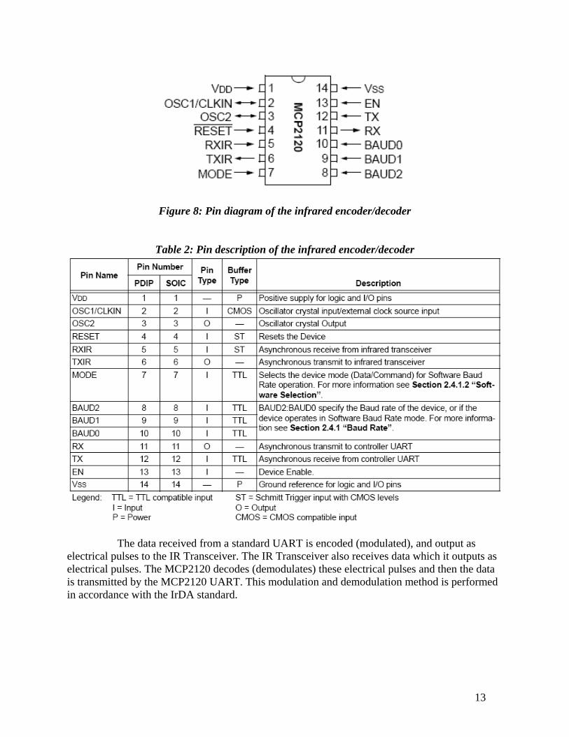
This device is a high-performance and fully-static infrared encoder/decoder. This device sits between a UART and an infrared (IR) optical transceiver. Its baud rate is user selectable to standard IrDA baud rates between 9600 baud to 115.2 kbaud. The maximum baud rate is 312.5 kbaud. The pin diagram and description of this infrared encoder/ decoder is given below:
13
Figure 8: Pin diagram of the infrared encoder/decoder
Table 2: Pin description of the infrared encoder/decoder
The data received from a standard UART is encoded (modulated), and output as electrical pulses to the IR Transceiver. The IR Transceiver also receives data which it outputs as electrical pulses. The MCP2120 decodes (demodulates) these electrical pulses and then the data is transmitted by the MCP2120 UART. This modulation and demodulation method is performed in accordance with the IrDA standard.
14
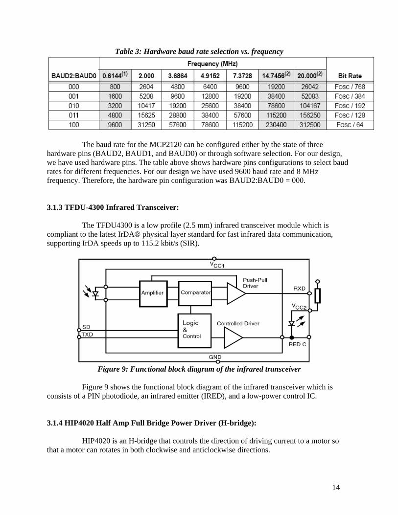
Table 3: Hardware baud rate selection vs. frequency
The baud rate for the MCP2120 can be configured either by the state of three hardware pins (BAUD2, BAUD1, and BAUD0) or through software selection. For our design, we have used hardware pins. The table above shows hardware pins configurations to select baud rates for different frequencies. For our design we have used 9600 baud rate and 8 MHz frequency. Therefore, the hardware pin configuration was BAUD2:BAUD0 = 000. 3.1.3 TFDU-4300 Infrared Transceiver:
The TFDU4300 is a low profile (2.5 mm) infrared transceiver module which is compliant to the latest IrDA® physical layer standard for fast infrared data communication, supporting IrDA speeds up to 115.2 kbit/s (SIR).
Figure 9: Functional block diagram of the infrared transceiver
Figure 9 shows the functional block diagram of the infrared transceiver which is
consists of a PIN photodiode, an infrared emitter (IRED), and a low-power control IC. 3.1.4 HIP4020 Half Amp Full Bridge Power Driver (H-bridge):
HIP4020 is an H-bridge that controls the direction of driving current to a motor so that a motor can rotates in both clockwise and anticlockwise directions.
15
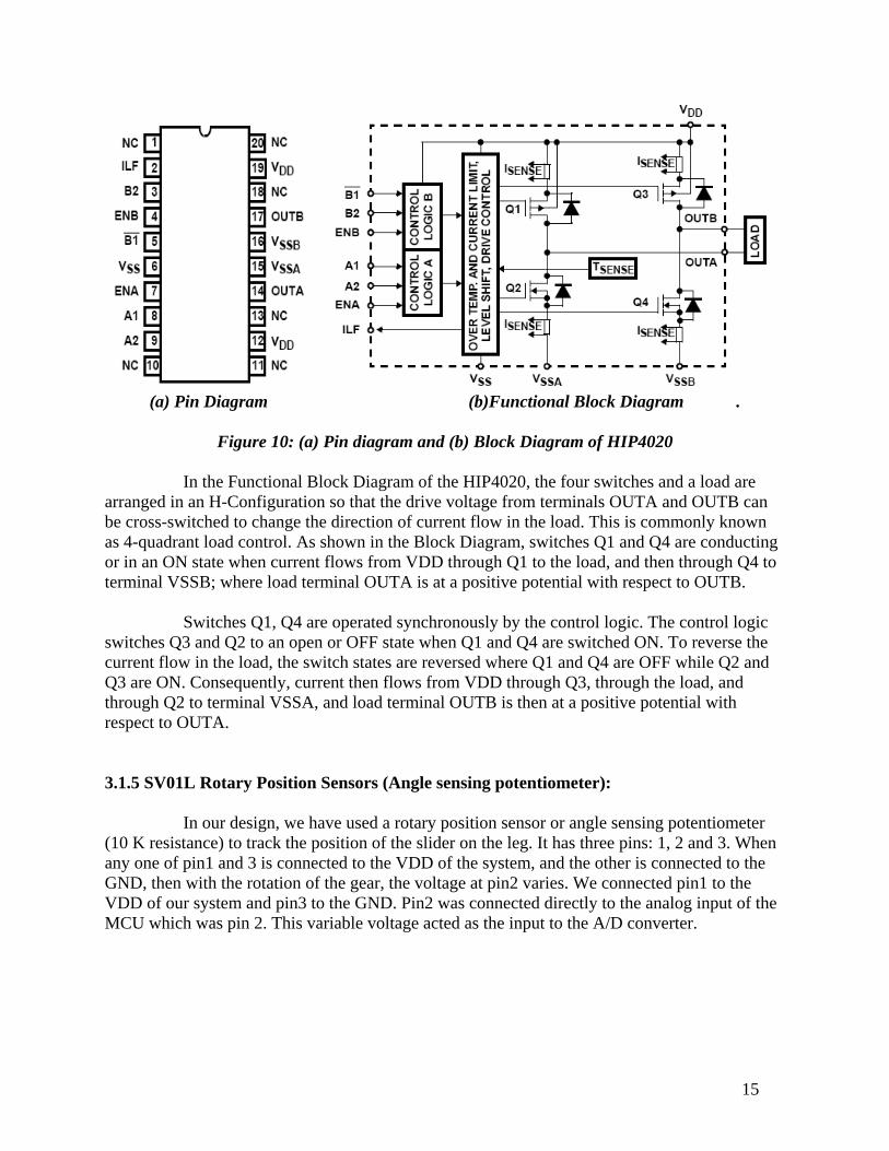
(a) Pin Diagram (b)Functional Block Diagram .
Figure 10: (a) Pin diagram and (b) Block Diagram of HIP4020
In the Functional Block Diagram of the HIP4020, the four switches and a load are
arranged in an H-Configuration so that the drive voltage from terminals OUTA and OUTB can be cross-switched to change the direction of current flow in the load. This is commonly known as 4-quadrant load control. As shown in the Block Diagram, switches Q1 and Q4 are conducting or in an ON state when current flows from VDD through Q1 to the load, and then through Q4 to terminal VSSB; where load terminal OUTA is at a positive potential with respect to OUTB.
Switches Q1, Q4 are operated synchronously by the control logic. The control logic
switches Q3 and Q2 to an open or OFF state when Q1 and Q4 are switched ON. To reverse the current flow in the load, the switch states are reversed where Q1 and Q4 are OFF while Q2 and Q3 are ON. Consequently, current then flows from VDD through Q3, through the load, and through Q2 to terminal VSSA, and load terminal OUTB is then at a positive potential with respect to OUTA. 3.1.5 SV01L Rotary Position Sensors (Angle sensing potentiometer):
In our design, we have used a rotary position sensor or angle sensing potentiometer (10 K resistance) to track the position of the slider on the leg. It has three pins: 1, 2 and 3. When any one of pin1 and 3 is connected to the VDD of the system, and the other is connected to the GND, then with the rotation of the gear, the voltage at pin2 varies. We connected pin1 to the VDD of our system and pin3 to the GND. Pin2 was connected directly to the analog input of the MCU which was pin 2. This variable voltage acted as the input to the A/D converter.

16
3.2 Software:
Both the body and the leg sub-modules have their own programs. The main task of the program of the body sub-module is to take the input from the user, encode the input data and send it to the leg sub-module serially as infrared signals. On the other hand, the task of the leg sub-module is to receive the infrared signals, decode the signals to get the input data and to control the slider motor depending on the input to change the leg stiffness to a certain level. The programs for both the body (transmitter) and the leg (receiver) sub-modules are given below:
The source code in C language for the body or transmitter part: #include <p18f2680.h> #include <stdio.h> #include <usart.h> #pragma config WDT = OFF void main (void) { ADCON1 = 0b00111111; TRISA = 0b11111111; OpenUSART( (USART_TX_INT_OFF & USART_RX_INT_OFF & USART_ASYNCH_MODE & USART_EIGHT_BIT & USART_CONT_RX & USART_BRGH_LOW) , 12 ); while (1) { WriteUSART (PORTA); } }
The source code in C language for the leg or receiver part: #include <p18f2680.h> #include <stdio.h> #include <usart.h> #include <pwm.h> #include <adc.h> #pragma config WDT = OFF void main (void) {
17
//Declare variables char new_sw, prev_sw; int d_theta, m_theta; //Configure or initialize I/O ports and peripherals ADCON1 = 0b00001111; TRISA = 0b00000000; //Configure or initialize the USART OpenUSART( (USART_TX_INT_OFF & USART_RX_INT_OFF & USART_ASYNCH_MODE & USART_EIGHT_BIT & USART_CONT_RX & USART_BRGH_LOW), 12 ); //Configure or initialize the 10 bit A/D converter OpenADC( ADC_FOSC_32 & ADC_RIGHT_JUST & ADC_12_TAD, ADC_CH0 & ADC_INT_OFF, 14 ); //Configure the PWM module OpenPWM(0x63); SetDCPWM1(160); //Infinite loop that controls the slider motor while (1) { do { new_sw = ReadUSART(); } while (prev_sw == new_sw); prev_sw = new_sw; m_theta = 0b0000111111111111; new_sw = new_sw & 0b00000111; if (new_sw == 0b00000000 || new_sw == 0b00000100) d_theta = 0b 0000 0000 0000 0000; else if (new_sw == 0b00000001 || new_sw == 0b00000101) d_theta = 0b 0000 0000 1111 1111; else if (new_sw == 0b00000010 || new_sw == 0b00000110) d_theta = 0b 0000 0001 1111 1111; else d_theta = 0b 0000 0010 1111 1111;
18
while (m_theta != d_theta) { ConvertADC(); while (BusyADC()); m_theta = ReadADC(); } } }
In the transmitter part, the first line enables digital I/O for all the pins of port A. The second line makes all the pins of port A to digital input pins. The third line calls a subroutine called ‘OpenUSART()’ which is defined in ‘usart.h’ header file. The main function of that sub-routine is to configure the usart for serial data transfer. Then we have used a while loop whose condition is always ‘true’ (1) that means it runs infinitely until we turn off the system. Inside the while loop we have used another subroutine called ‘WriteUSART ()’ which is also defined in the ‘usart.h’ header file. This function writes the 8-bit data that is passed as an argument to the ‘TXREG’ register of the USART and transmits the data as infrared signals.
On the other hand, in the transmitter part, at first the variables are declared, then the I/O ports and the peripherals (USART, PWM, A/D converter) are configured. Then the infinite while loop starts that at first receive and decode the data from the infrared signals, and then depending on the data it controls the slider motor.
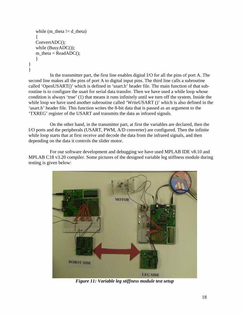
For our software development and debugging we have used MPLAB IDE v8.10 and MPLAB C18 v3.20 compiler. Some pictures of the designed variable leg stiffness module during testing is given below:
Figure 11: Variable leg stiffness module test setup
19
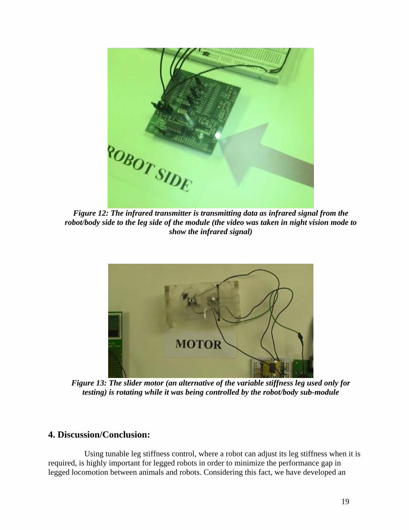
Figure 12: The infrared transmitter is transmitting data as infrared signal from the
robot/body side to the leg side of the module (the video was taken in night vision mode to show the infrared signal)
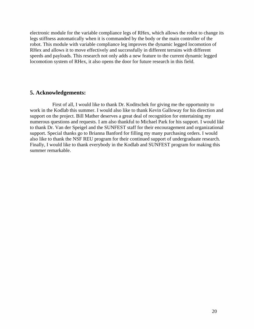
Figure 13: The slider motor (an alternative of the variable stiffness leg used only for
testing) is rotating while it was being controlled by the robot/body sub-module 4. Discussion/Conclusion:
Using tunable leg stiffness control, where a robot can adjust its leg stiffness when it is required, is highly important for legged robots in order to minimize the performance gap in legged locomotion between animals and robots. Considering this fact, we have developed an
20
electronic module for the variable compliance legs of RHex, which allows the robot to change its legs stiffness automatically when it is commanded by the body or the main controller of the robot. This module with variable compliance leg improves the dynamic legged locomotion of RHex and allows it to move effectively and successfully in different terrains with different speeds and payloads. This research not only adds a new feature to the current dynamic legged locomotion system of RHex, it also opens the door for future research in this field. 5. Acknowledgements:
First of all, I would like to thank Dr. Koditschek for giving me the opportunity to work in the Kodlab this summer. I would also like to thank Kevin Galloway for his direction and support on the project. Bill Mather deserves a great deal of recognition for entertaining my numerous questions and requests. I am also thankful to Michael Park for his support. I would like to thank Dr. Van der Speigel and the SUNFEST staff for their encouragement and organizational support. Special thanks go to Brianna Banford for filling my many purchasing orders. I would also like to thank the NSF REU program for their continued support of undergraduate research. Finally, I would like to thank everybody in the Kodlab and SUNFEST program for making this summer remarkable.
21
6. References:
1. Ferris, D., Louie, M., and Farley, C., “Running in the real world: Adjusting leg stiffness for different surfaces,” Proceedings of the Royal Society London (Series B – Biological Sciences), Vol. 265, Jun 1998, p 989–994. [Database: ISI Web of Knowledge]
2. Saranli, U., Buehler M., and Koditschek, D., “RHex: A simple and highly
mobile hexapod robot,” International Journal of Robotics Research, v 20, n 7, Jul 2001, p 616-31. [Database: ISI Web of Knowledge]
3. Galloway, K., Clark, J., and Koditschek, D., “Design of a multi-directional
variable stiffness leg for dynamic running,” Proceedings of IMECE2007-41318, ASME International Mechanical Engineering Congress and Exposition, Nov 2007.
4. Blickhan, R., Full, R.J., “Similarity in multilegged locomotion: Bouncing
like a monopode,” Journal of Comparative Physiology, v A, n 173, Nov 1993, p 509-517. [Database: ISI Web of Knowledge]
5. Dickinson, M., Farley, C., Full, R., Koehl, M., Kram, R., and Lehman, S.
“How animals move: An integrative view,” Science, v 288, issue 5463, Apr 2000, p100-106. [Database: ISI Web of Knowledge]
6. Blickhan, R., “The spring-mass model for running and hopping,” Journal of
Biomechanics, v 22, issue 11-12, 1989, p 1217-1227. [Database: ISI Web of Knowledge]
7. Farley, C.T. and Ferris, D.P., “Biomechanics of walking and running:
Center of mass movements to muscle action,” Exercise and Sport Sciences Reviews, volume 26, chapter 10, 1998, p 253-285. [Database: ISI Web of Knowledge]
8. Sutherland, I.E., Ullner, M.K., “Footprints in the Asphalt,” International
Journal of Robotics Research, v 3, n 2, 1984, p 29-36. [Database: ISI Web of Knowledge]
9. Cham, J.G., Bailey S., Clark J.E., et al., “Fast and Robust: Hexapedal
Robots via Shape Deposition Manufacturing,” International Journal of Robotics Research, v 21, n 10-11, Oct.-Nov. 2002, p 869-82. [Database: ISI Web of Knowledge]
22
7. APPENDIX Microcontroller Registers
1. USART Registers
A) TXSTA:
23
B) RCSTA:
24
C) BAUDCON:
25
2. PWM module initialization and control registers
A) CCP1CON:
B) T2CON:

26
3. A/D converter initialization and control registers A) ADCON0:
27
B) ADCON1:

28
C) ADCON2:
29
All these information have been obtained from the microcontroller data sheet. More details information about these registers can be found in the microcontroller datasheet (http://ww1.microchip.com/downloads/en/DeviceDoc/39625c.pdf).