
Optimization of Economiser Design for the Enhancement of...
6
International Journal of Applied Research In Mechanical Engineering (IJARME), ISSN: 2231 –5950 Volume-1, Issue-2, 2011 52 Optimization of Economiser Design for the Enhancement of Heat Transfer Coefficient A. D. Patil 1 , P. R. Baviskar 2 , M. J. Sable 3 & S. B. Barve 4 Department of Mechanical Engineering, Rajarshi Shahu College of Engineering, Pune-411033, Maharashtra, India E-mail : [email protected] Abstract - Energy saving and efficiency are the key issues in power generation system not only from the view point of fuel consumption, but also for the protection of global environment. Flue gas ducts are the major parts of oil-fired power plant, which are used to exhaust flue gases from boiler. This paper presents an approach for the optimization of economiser design. The aim of this work is to develop methodology which finds optimization of economiser design. CFD analysis is used to compare the new economiser design with traditional strategies. The most economical solution of this problem seems to distribute gas flow uniformly at inlet of economiser by using vanes. So that effective heat transfer can be obtained to reduce the number of tubes of existing model. In the present work commercial software Fluent is used for the 3D simulation using its inbuilt K- Reliable model. Optimization of economiser is done for effective heat transfer with reducing number of tubes required. Key words - Economiser ,Eulerian formulation, K- model. I. INTRODUCTION Economiser performs a key function in providing high overall boiler thermal efficiency by recovering the low level energy from the flue gas before it is exhausted to the atmosphere. Economiser recovers the energy by heating the boiler feedwater. Economiser are basically tubular heat transfer surfaces used to preheat boiler feed water before it enters the steam drum or furnace surfaces. Economiser reduces operating costs or economies on fuel by recovering extra energy from the flue gas. The ultimate goal of economiser design is to achieve necessary heat transfer at minimum cost. A key design criterion for economiser is maximum allowable flue gas velocity. Higher velocity provides better heat transfer and reduces capital cost. So detail analysis of flue gas flow is needed to improve the duct design and its internals.CFD modeling is a good tool to improve the efficiency of economiser by reducing the number of tubes of existing model. Duct having rectangular cross sectional area is normally used in power plant.[5]Gas flow distribution over heating equipment is very critical problem in power plant. By providing inlet guide vanes at economiser inlet duct, we get effective heat transfer in economiser. The other motivation for this work is to maintain the proper pitch between tubes for effective distribution of gas over tubes [6]. CFD tool is used to check the gas flow over tubes. Flue gas is produced in furnace and it passes through superheater, convection bank, and then economizer before it goes to chimney. For sustainable development of thermal electric power plant, the power industries have to adopt state-of-art technologies to increase the heat transfer rates through heat exchanger.CFD simulation has been a good tool in identifying the possibilities of increasing the heat transfer [7] II. SIMULATION SET UP AND DATA INPUT In Fluent, the governing equations are discretized by using the finite Volume method The pressure- velocity coupling is achieved through the SIMPLE algorithm.[3]The grid-independent study is done for all cases .All simulations are run in Fluent K- reliable model. Boundary conditions used are flue gas mass flow rate and temperature. It is assumed that all particles have attended their terminal velocity and have entered perpendicular to the tube. The geometry of actual flue gas duct, its internal, tubes created in ICEM. Drawings of duct are used for geometry creation. Meshing is done in ICEM. Inlet surface meshed and volume meshing done with hexahedral. Further refinement of mesh is done by adaption by using velocity gradient. Numbers of cells are varying from 1.7 to1.8 million as per geometry dimensions and requirement for grid independent solution. Simulation done on existing geometry of duct and then with modified geometry by adding vanes.
-
Upload
duongkhanh -
Category
Documents
-
view
223 -
download
4
Transcript of Optimization of Economiser Design for the Enhancement of...

International Journal of Applied Research In Mechanical Engineering (IJARME), ISSN: 2231 –5950 Volume-1, Issue-2, 2011 52
Optimization of Economiser Design for the Enhancement of
Heat Transfer Coefficient
A. D. Patil1, P. R. Baviskar2, M. J. Sable3 & S. B. Barve4
Department of Mechanical Engineering, Rajarshi Shahu College of Engineering, Pune-411033, Maharashtra, India E-mail : [email protected]
Abstract - Energy saving and efficiency are the key issues in power generation system not only from the view point of fuel consumption, but also for the protection of global environment. Flue gas ducts are the major parts of oil-fired power plant, which are used to exhaust flue gases from boiler. This paper presents an approach for the optimization of economiser design. The aim of this work is to develop methodology which finds optimization of economiser design. CFD analysis is used to compare the new economiser design with traditional strategies. The most economical solution of this problem seems to distribute gas flow uniformly at inlet of economiser by using vanes. So that effective heat transfer can be obtained to reduce the number of tubes of existing model. In the present work commercial software Fluent is used for the 3D simulation using its inbuilt K- Reliable model. Optimization of economiser is done for effective heat transfer with reducing number of tubes required.
Key words - Economiser ,Eulerian formulation, K- model.
I. INTRODUCTION
Economiser performs a key function in providing high overall boiler thermal efficiency by recovering the low level energy from the flue gas before it is exhausted to the atmosphere. Economiser recovers the energy by heating the boiler feedwater. Economiser are basically tubular heat transfer surfaces used to preheat boiler feed water before it enters the steam drum or furnace surfaces. Economiser reduces operating costs or economies on fuel by recovering extra energy from the flue gas. The ultimate goal of economiser design is to achieve necessary heat transfer at minimum cost. A key design criterion for economiser is maximum allowable flue gas velocity. Higher velocity provides better heat transfer and reduces capital cost. So detail analysis of flue gas flow is needed to improve the duct design and its internals.CFD modeling is a good tool to improve the efficiency of economiser by reducing the number of tubes of existing model. Duct having rectangular cross sectional area is normally used in power plant.[5]Gas flow distribution over heating equipment is very critical problem in power plant. By providing inlet guide vanes at economiser inlet duct, we get effective heat transfer in economiser.
The other motivation for this work is to maintain the proper pitch between tubes for effective distribution of gas over tubes [6]. CFD tool is used to check the gas flow over tubes. Flue gas is produced in furnace and it
passes through superheater, convection bank, and then economizer before it goes to chimney. For sustainable development of thermal electric power plant, the power industries have to adopt state-of-art technologies to increase the heat transfer rates through heat exchanger.CFD simulation has been a good tool in identifying the possibilities of increasing the heat transfer [7]
II. SIMULATION SET UP AND DATA INPUT
In Fluent, the governing equations are discretized by using the finite Volume method The pressure-velocity coupling is achieved through the SIMPLE algorithm.[3]The grid-independent study is done for all cases .All simulations are run in Fluent K- reliable model. Boundary conditions used are flue gas mass flow rate and temperature. It is assumed that all particles have attended their terminal velocity and have entered perpendicular to the tube. The geometry of actual flue gas duct, its internal, tubes created in ICEM. Drawings of duct are used for geometry creation. Meshing is done in ICEM. Inlet surface meshed and volume meshing done with hexahedral. Further refinement of mesh is done by adaption by using velocity gradient. Numbers of cells are varying from 1.7 to1.8 million as per geometry dimensions and requirement for grid independent solution. Simulation done on existing geometry of duct and then with modified geometry by adding vanes.
Optimization of Economiser Design for the Enhancement of Heat Transfer Coefficient
International Journal of Applied Research In Mechanical Engineering (IJARME), ISSN: 2231 –5950 Volume-1, Issue-2, 2011 53
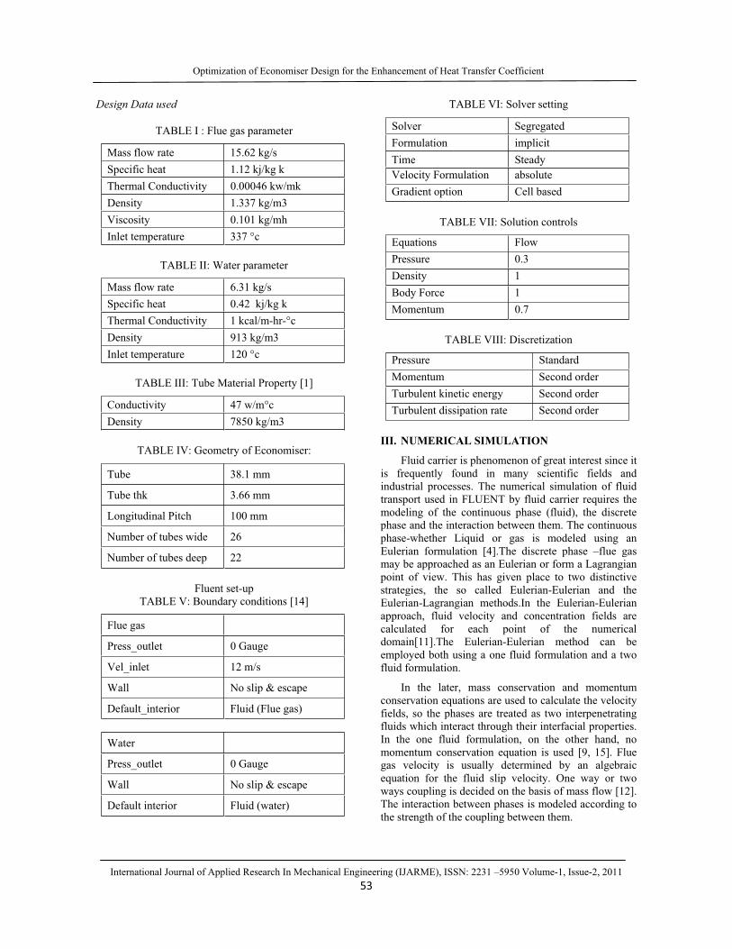
Design Data used
TABLE I : Flue gas parameter
Mass flow rate 15.62 kg/s Specific heat 1.12 kj/kg k Thermal Conductivity 0.00046 kw/mk Density 1.337 kg/m3 Viscosity 0.101 kg/mh Inlet temperature 337 °c
TABLE II: Water parameter
Mass flow rate 6.31 kg/s Specific heat 0.42 kj/kg k Thermal Conductivity 1 kcal/m-hr-°c Density 913 kg/m3 Inlet temperature 120 °c
TABLE III: Tube Material Property [1]
Conductivity 47 w/m°c Density 7850 kg/m3
TABLE IV: Geometry of Economiser:
Tube 38.1 mm
Tube thk 3.66 mm
Longitudinal Pitch 100 mm
Number of tubes wide 26
Number of tubes deep 22
Fluent set-up TABLE V: Boundary conditions [14]
Flue gas
Press_outlet 0 Gauge
Vel_inlet 12 m/s
Wall No slip & escape
Default_interior Fluid (Flue gas)
Water
Press_outlet 0 Gauge
Wall No slip & escape
Default interior Fluid (water)
TABLE VI: Solver setting
Solver Segregated Formulation implicit Time Steady Velocity Formulation absolute Gradient option Cell based
TABLE VII: Solution controls
Equations Flow Pressure 0.3 Density 1 Body Force 1 Momentum 0.7
TABLE VIII: Discretization
Pressure Standard Momentum Second order Turbulent kinetic energy Second order Turbulent dissipation rate Second order
III. NUMERICAL SIMULATION
Fluid carrier is phenomenon of great interest since it is frequently found in many scientific fields and industrial processes. The numerical simulation of fluid transport used in FLUENT by fluid carrier requires the modeling of the continuous phase (fluid), the discrete phase and the interaction between them. The continuous phase-whether Liquid or gas is modeled using an Eulerian formulation [4].The discrete phase –flue gas may be approached as an Eulerian or form a Lagrangian point of view. This has given place to two distinctive strategies, the so called Eulerian-Eulerian and the Eulerian-Lagrangian methods.In the Eulerian-Eulerian approach, fluid velocity and concentration fields are calculated for each point of the numerical domain[11].The Eulerian-Eulerian method can be employed both using a one fluid formulation and a two fluid formulation.
In the later, mass conservation and momentum conservation equations are used to calculate the velocity fields, so the phases are treated as two interpenetrating fluids which interact through their interfacial properties. In the one fluid formulation, on the other hand, no momentum conservation equation is used [9, 15]. Flue gas velocity is usually determined by an algebraic equation for the fluid slip velocity. One way or two ways coupling is decided on the basis of mass flow [12]. The interaction between phases is modeled according to the strength of the coupling between them.

A
International
A. K- Turbu
It is the considered thebe stable andestablished reFLUENT the fine. The scapproach to im
B. Geometry
Geometryin Pro-E. Tparametric meconomiser inmodeled as paProE. Wire frfigure 1.
Robustnesfunctions allogrids, which iwall functions
C. Meshing:
The mostdiscretization tetrahedral memesh gives beHexahedral mmeshing softsubdivided inrectangular elsignificant grasymmetry ofsimplifies geom
Fig. 1 : G
Optimiz
l Journal of App
ulence model
most generale industry standd numericallyegime of preK- turbulenc
calable wall tmprove
y Modeling:
y of the econoThis software modeling. Thnlet duct, vanart and assembrame view of
ss and accurow solution onis significant i [10, 13]
t important pof geometry.
eshes are used etter results, bu
mesh is generaftware. The nto a computalements of suadient in velo
f the planes, metry.
Geometry of inl
zation of Econom
plied Research In
-purpose CFDdard model. It
y robust and edictive capabce model usesthe scalable
miser inlet dugives an a
he assembly nes, and econbled together in
the inlet duct
racy when tn arbitrarily fiimprovement
part in CFD Generally he
for CFD codeut meshing is ated in ICEMinterior wate
ational mesh ufficient enougocity [14]. Co
only repres
let duct and Ec
miser Design for
n Mechanical En
D code and is has proven to has a well-
bility. Within mesh is very wall-function
uct is modeled advantage of
consists ofnomiser tubes n assembly oft is shown in
the near-wallfine near wall over standard
simulation is exahedral and es. Hexahedral very difficult.
M CFD by in er space is consisting of
gh to capture onsidering the sentative part
onomiser
r the Enhanceme
ngineering (IJAR54
ff
f
f
Flue Inlet
V
ent of Heat Trans
RME), ISSN: 223
Fig. 2 : Inlet d
Fig. 3 : Mes
Fig.4
Fig. 5
Gas
Wall
ane
sfer Coefficient
31 –5950 Volum
duct geometry
shing of ducts a
: Tube geome
: Meshing of t
Flue Gas Ou
me-1, Issue-2, 20
with vanes
and vanes
try
tube
utlet
011
Wall
International
Fig
Fig
Fig. 8
Fig. 9
Optimiz
l Journal of App
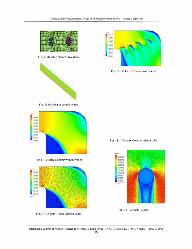
. 6: Meshing b
g. 7: Meshing o
8: Velocity Con
9 : Velocity Ve
zation of Econom
plied Research In
between two tub
of complete tub
ntour without v
ector without v
miser Design for
n Mechanical En
bes
be
vanes
vanes
r the Enhanceme
ngineering (IJAR55
ent of Heat Trans
RME), ISSN: 223
Fig. 10 : Velo
Fig. 11 : Velo
Fig. 12
sfer Coefficient
31 –5950 Volum
ocity Contour w
ocity Contour i
2 : Velocity Ve
me-1, Issue-2, 20
with vanes
inlet of tube
ector
011

International
Fig.
Fig. 14
Fig.
Fi
Optimiz
l Journal of App
13 : Velocity
4 : Pressure Co
15 : Pressure C
ig. 16 : Tube in
zation of Econom
plied Research In
Vector with va
ontour without
Contour with v
nlet temperatur
miser Design for
n Mechanical En
anes
vanes
vanes
re
r the Enhanceme
ngineering (IJAR56
IV. RES
Inlet Du
Simduct wicontour (8,9,13).of econo
ent of Heat Trans
RME), ISSN: 223
Fig. 17 : Tem
Fig. 18 : Tu
Fig. 19 : Ma
SULTS AND
ct without van
mulation is donithout vanes and pressure
.It is very cleaomiser is not u
sfer Coefficient
31 –5950 Volum
mperature rise a
ube outlet temp
ss flow rate ac
DISCUSSION
es
ne on existinand results ocontour are p
ar that velocityuniform. Mass
me-1, Issue-2, 20
across tube
perature
ross tubes
N
ng economiser of velocity vpresented in f
y profile at theflow distributi
011
inlet vector, figure e inlet ion of

Optimization of Economiser Design for the Enhancement of Heat Transfer Coefficient
International Journal of Applied Research In Mechanical Engineering (IJARME), ISSN: 2231 –5950 Volume-1, Issue-2, 2011 57
gas over tubes is also non-uniform. Due to this heat transfer across tubes is also ineffective, result of this increases heat transfer area.
Modification with inlet vanes
The results in the form of velocity, pressure and turbulence contours are studied based on fluid mechanics applications, geometry modification are implemented by providing vanes [2,8] at inlet to the original geometry and appropriate mesh is generated and flow analysis is done in CFD software. Care is needed in selection of proper models, grid independence studies. From result Fig (10,13) it indicates that velocity profile at the inlet of economiser is uniform. Mass flow distribution of gas over tubes is also uniform.(Fig 19)
Optimization of Economiser
The outlet at duct is divided into 26 strips of equal 70 mm length. One deep row of 22 tubes is considered for analysis. In analysis feed water inlet temperature is 120 °c and flue gas inlet temperature is 337 °c is considered. The flue gas is flowing over tubes from top and feed water enters through bottom of economiser module. Combined analysis of flue gas over tubes and water through tubes is done with help of K- model in CFD. The temperature required at outlet of economiser is 165°c but we are getting this temperature after 19th row. Actual temperature rise is required 45°c. But we are getting the temperature rise of 54°c.In this way we can reduce 78 number of economiser tubes which will reduce the cost.
V. CONCLUSION
Specific issues like the undesirable effects of mal-distribution of heating and heated medium have been understood through applications of CFD codes. Gas flow distribution or heat transfer into the economiser section is improved through use of guide vanes at inlet of economiser duct.
Analysis of economiser module was carried out using K- model to predict the economiser feed water outlet temperature. The model was validated and economiser size optimized by reducing the number of tubes of module by enhancing the heat transfer across the module. The results indicated that a required water temperature obtained after 19 th row of economiser tube. The results of simulation indicate the uniform flow of gas over tubes after adding the vanes at inlet of module. The results were compared with site data and showed good agreement. CFD has earned a reputation of troubleshooting technique par excellence and extensively in testing out new design variant. The results of the CFD analysis can be used in enhancing the heat transfer in design of different type of economiser. The
model developed is better equipped to predict the economiser outlet temperature. Future direction would include development of model to predict soot formation over tubes.
In days to come, CFD would become integral design tool to predict various operating scenarios of the product and thus improving the effectiveness of design process.
REFERNCES [1] J B Kitto and S C Stultz “Steam – its generation and
use” The Babcock &Wilcox Company, 40th edition
[2] Charles E Baukal “Combustion Handbook”, the John Zink Company.
[3] John D Anderson “Computational Fluid Dynamics the basics and application” McGraw-Hill, Dept. of Aerospace Engineering, University of Maryland.
[4] Suhas V Patankar “Numerical Heat Transfer and Fluid Dynamics”.
[5] P.K.NAG“Power Plant Engineering”,2006, Tata McGraw-Hill Publication.
[6] PMV Subbarao “CFD Analysis of Flue Gas Duct”, 05 Jan 2010, IIT, Delhi.
[7] V Ganapathy “Industrial Boilers and Heat Recovery Steam Generators, CRC”,ABCO industries, Abilene, Texas, USA.
[8] S. Jayanti “Techniques for flow passage optimization in air and flue gas ducting in boilers”,BHEL National conference on CFD Application ,Hyderabad, 17-18 Nov,2006.
[9] Yogesh Jaluria “Design and Optimization of Thermal System”, Rutgers,The state University of New Jersey.
[10] FLUENT User Guide.
[11] Hryb,D,, Cardozo, M., Ferro, S., and Goldschmit M., 2009 “Particle transport in turbulent flow using both lagrangian and Eulerian formulations”,Int. Commun.Heat Mass Transfer.
[12] N. hedge, I. Han, T.W. Lee, R.P.Roy. (2007),”Flow and heat transfer in Heat Recovery Steam Generator”. ASME Vol.129
[13] P.J. Stopford,” Recent applications of CFD modelling in the power generation and combustion industrie”, Appl.math. Modell 26(2002)
[14] Al-Khalidy Neihad,”Design optimization Of industrial ducts using CFD”,CSIRO,10-12 Dec, 2003, Australia.
[15] M.EI Sayed et al(2005)-“Shape optimization with computational fluid dynamics”,Advances in Engg Software.


