Comparative Study of ECONOMISER Using the CFD · PDF fileInternational OPEN ACCESS Journal Of...
6
International OPEN ACCESS Journal Of Modern Engineering Research (IJMER) | IJMER | ISSN: 2249–6645 | www.ijmer.com | Vol. 4 | Iss. 4 | Apr. 2014 | 1 | Comparative Study of ECONOMISER Using the CFD Analysis K. Sainath 1 , Mohd Salahuddin 2 , Mohammed Shafi 3 , Dr. T.K.K Reddy 4 1,2,3 Mechanical Engineering Department Sreyas Institute of Engineering & Technology, Nagole, Hyderabad-500 085, INDIA 4, Mechanical Engineering Department Jawaharlal Nehru Tech. University Hyderabad, Kukatpally, Hyderabad -500 085, INDIA I. Introduction In boilers, economizers are heat exchange devices that heat fluids, usually water, up to but not normally beyond the boiling point of that fluid. Economizers are so named because they can make use of the enthalpy in fluid streams that are hot, but not hot enough to be used in a boiler, thereby recovering more useful enthalpy and improving the boiler's efficiency.Using an economizer can increase feed water temperature and reduce the amount of heat required in a boiler. The amount of heat that can be transferred and the upper limit of feed water temperature depend primarily on boiler (steam) pressure and temperature of flue gases discharged from the boiler. Transferring heat from the flue gases to the feed water will lower flue gas temperature.Economizer reduces operating costs or economies on fuel by recovering extra energy from the flue gas. The ultimate goal of economizer design is to achieve necessary heat transfer at minimum cost. A key design criterion for economizer is maximum allowable flue gas velocity. Higher velocity provides better heat transfer and reduces capital cost. The control over the fluid flow is absolute to increase the efficiency of the economizer. And CFD modelling is a good tool to study the fluid flow, to improve the efficiency of economizer by reducing the number of tubes of existing model. The strategy of how to recover this heat depends in part on the temperature of the waste heat gases and the economics involved. Large quantity of hot flue gases is generated from Boilers, Kilns, Ovens and Furnaces. If some of this waste heat could be recovered, a considerable amount of primary fuel could be saved.CFD has evolved as important tool for modelling of coal fired boiler and it can useful to quantify the fluid flow field and pressure distribution with the boiler economizer. Hence FLUENT software was used to study the velocity and pressure distribution of the working fluid inside the economizer. II. Describing the Model and Simulations A three dimensional model of an economizer is model with the standard specifications and dimensions from an industry, by using the software tool ICEM CFD. In the ICEM CFD, the economizer was modelled and meshed with the tetrahedral scheme. For this analysis, single unit of economizer is considered and modelled to observe the flow phenomenon and pressure drop in each step tube and the overall pressure drop of the economizer unit. It consists of 12 parallel pipes of 30 meters long and 23 C-shaped connecting tubes on either side of the parallel tube as shown in figure1. Abstract: This paper presents a simulation of the economizer zone, which allowsstudying the flow patterns developed in the fluid, while it flows along the length of the economizer. The past failure details revelsthat erosion is more in U-bend areas of Economizer Unit because of increase in flue gas velocity near these bends. But it isobserved that the velocity of flue gases surprisingly increases near the lower bends as compared to upper ones. The model issolved using conventional CFD techniques by FLUENT software. In which the individual tubes are treated as sub-gridfeatures. A geometrical model is used to describe the multiplicity of heat-exchanging structures and the interconnectionsamong them. The Computational Fluid Dynamics (CFD) approach is utilised for the creation of a three-dimensional modelof the economizer coil of single column tube. With equilibrium assumption applied for description of the system chemistry. The flue gastemperature, pressure and velocity field of fluid flow within an economizer tube using the actual boundary conditions havebeen analysed using CFD tool. This study is a classic example of numericalinvestigation into the problem of turbulent flows in U- bends for the pressure drop and velocity variation in the flow so that it helps in design the economizer with low pressure losses for the thermal power plants. Keywords: Economizer, flow efficiencies, CFD, pressure drops, FLUENT, fluid dynamics.
Transcript of Comparative Study of ECONOMISER Using the CFD · PDF fileInternational OPEN ACCESS Journal Of...

International
OPEN ACCESS Journal
Of Modern Engineering Research (IJMER)
| IJMER | ISSN: 2249–6645 | www.ijmer.com | Vol. 4 | Iss. 4 | Apr. 2014 | 1 |
Comparative Study of ECONOMISER Using the CFD Analysis
K. Sainath1, Mohd Salahuddin
2, Mohammed Shafi
3, Dr. T.K.K Reddy
4
1,2,3Mechanical Engineering Department Sreyas Institute of Engineering & Technology, Nagole,
Hyderabad-500 085, INDIA 4, Mechanical Engineering Department Jawaharlal Nehru Tech. University Hyderabad, Kukatpally,
Hyderabad -500 085, INDIA
I. Introduction In boilers, economizers are heat exchange devices that heat fluids, usually water, up to but not
normally beyond the boiling point of that fluid. Economizers are so named because they can make use of
the enthalpy in fluid streams that are hot, but not hot enough to be used in a boiler, thereby recovering more
useful enthalpy and improving the boiler's efficiency.Using an economizer can increase feed water temperature
and reduce the amount of heat required in a boiler. The amount of heat that can be transferred and the upper
limit of feed water temperature depend primarily on boiler (steam) pressure and temperature of flue gases
discharged from the boiler. Transferring heat from the flue gases to the feed water will lower flue gas
temperature.Economizer reduces operating costs or economies on fuel by recovering extra energy from the flue
gas. The ultimate goal of economizer design is to achieve necessary heat transfer at minimum cost. A key design criterion for economizer is maximum allowable flue gas velocity. Higher velocity provides better heat transfer
and reduces capital cost. The control over the fluid flow is absolute to increase the efficiency of the economizer.
And CFD modelling is a good tool to study the fluid flow, to improve the efficiency of economizer by reducing
the number of tubes of existing model. The strategy of how to recover this heat depends in part on the
temperature of the waste heat gases and the economics involved. Large quantity of hot flue gases is generated
from Boilers, Kilns, Ovens and Furnaces. If some of this waste heat could be recovered, a considerable amount
of primary fuel could be saved.CFD has evolved as important tool for modelling of coal fired boiler and it can
useful to quantify the fluid flow field and pressure distribution with the boiler economizer. Hence FLUENT
software was used to study the velocity and pressure distribution of the working fluid inside the economizer.
II. Describing the Model and Simulations A three dimensional model of an economizer is model with the standard specifications and dimensions
from an industry, by using the software tool ICEM CFD. In the ICEM CFD, the economizer was modelled and
meshed with the tetrahedral scheme. For this analysis, single unit of economizer is considered and modelled to
observe the flow phenomenon and pressure drop in each step tube and the overall pressure drop of the
economizer unit.
It consists of 12 parallel pipes of 30 meters long and 23 C-shaped connecting tubes on either side of the
parallel tube as shown in figure1.
Abstract: This paper presents a simulation of the economizer zone, which allowsstudying the flow patterns developed in the fluid, while it flows along the length of the economizer. The past failure
details revelsthat erosion is more in U-bend areas of Economizer Unit because of increase in flue gas
velocity near these bends. But it isobserved that the velocity of flue gases surprisingly increases near
the lower bends as compared to upper ones. The model issolved using conventional CFD techniques by
FLUENT software. In which the individual tubes are treated as sub-gridfeatures. A geometrical model
is used to describe the multiplicity of heat-exchanging structures and the interconnectionsamong them.
The Computational Fluid Dynamics (CFD) approach is utilised for the creation of a three-dimensional
modelof the economizer coil of single column tube. With equilibrium assumption applied for
description of the system chemistry. The flue gastemperature, pressure and velocity field of fluid flow
within an economizer tube using the actual boundary conditions havebeen analysed using CFD tool. This study is a classic example of numericalinvestigation into the problem of turbulent flows in U-
bends for the pressure drop and velocity variation in the flow so that it helps in design the economizer
with low pressure losses for the thermal power plants.
Keywords: Economizer, flow efficiencies, CFD, pressure drops, FLUENT, fluid dynamics.

Comparative study of ECONOMISER using the CFD analysis
| IJMER | ISSN: 2249–6645 | www.ijmer.com | Vol. 4 | Iss. 4 | Apr. 2014 | 2 |
III. Meshing & Solving The modelled geometry was under gone discretization process, with the help of Mesh tool available in
the ICEM CFD tool. On meshing the geometry in the ICEM CFD tool, it was observed to had quality of 0.72 in
the relevance standards of the ICEM CFD tool. With the satisfactory mesh quality, it is found that it has:
IV. Boundary Conditions On discretising the geometry, the specific boundary conditions should be assigned to the surface of the
elements, which decides the behaviour of the element to the solver. The following working and boundary
conditions are to evaluate the performance between the right angled and circular tube pipes. In the fluent solver, the following boundary and solver conditions are used:
Model:
Solve under energy equation with viscosity k-epsilon equation with standard wall function, with the
possibility of viscous heating.
Material: Steel for the pipe wall and water vapour for the volumetric domain (fluid).

Comparative study of ECONOMISER using the CFD analysis
| IJMER | ISSN: 2249–6645 | www.ijmer.com | Vol. 4 | Iss. 4 | Apr. 2014 | 3 |
Boundary conditions:
Inlet as mass flow rate as 71.5572 kg/s; with inlet pressure as 450000; with temperature 531 K; and
with turbulent kinetic energy 1 m2/s2; turbulent dissipation rate 1 m2/s3; outlet as default outflow conditions and the wall temperature as 300 K.
V. Results

Comparative study of ECONOMISER using the CFD analysis
| IJMER | ISSN: 2249–6645 | www.ijmer.com | Vol. 4 | Iss. 4 | Apr. 2014 | 4 |
Comparative study of ECONOMISER using the CFD analysis
| IJMER | ISSN: 2249–6645 | www.ijmer.com | Vol. 4 | Iss. 4 | Apr. 2014 | 5 |
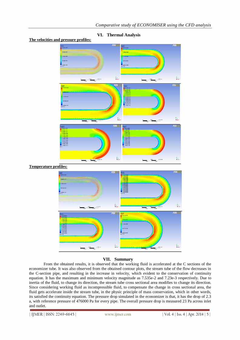
VI. Thermal Analysis The velocities and pressure profiles:
Temperature profiles:
VII. Summary From the obtained results, it is observed that the working fluid is accelerated at the C sections of the
economizer tube. It was also observed from the obtained contour plots, the stream tube of the flow decreases in
the C-section pipe, and resulting in the increase in velocity, which evident to the conservation of continuity
equation. It has the maximum and minimum velocity magnitude as 7.535e-2 and 7.23e-3 respectively. Due to inertia of the fluid, to change its direction, the stream tube cross sectional area modifies to change its direction.
Since considering working fluid as incompressible fluid, to compensate the change in cross sectional area, the
fluid gets accelerate inside the stream tube, in the physic principle of mass conservation, which in other words,
its satisfied the continuity equation. The pressure drop simulated in the economizer is that, it has the drop of 2.3
a, with reference pressure of 476000 Pa for every pipe. The overall pressure drop is measured 23 Pa across inlet
and outlet.
Comparative study of ECONOMISER using the CFD analysis
| IJMER | ISSN: 2249–6645 | www.ijmer.com | Vol. 4 | Iss. 4 | Apr. 2014 | 6 |
REFRENCESS [1.] Recovery boilers, American Forest & Paper Association, Tappi Press, Atlanta, 1997, ISBN 0-9625985-3.
[2.] Adams T.N., and Frederick W.J., Kraft recovery boiler physical and chemical processes. [3.] American Paper Institute, New York, NY, 1988. [4.] Backman R., Hupa M., and Hyöty P., Tappi J., 67 (12): 60-64, 1984. [5.] Björklund H., Warnquist B., Pettersson B., Inside a Kraft recovery boiler – combustion of (high sulfidity) black
liquor at high solids content, Tappi/CPPA 1989 International Chemical Recovery Conference Proceedings, Tappi Press, Atlanta, pp. 177-182, 1989.
[6.] Blasiak W., Vaclavinek J., and Collin, R., Investigation of the flow conditions in a recovery boiler with respect to gases, droplets and dust, Project number: 1192, Department of Heat and Furnace Technology, Royal Institute of Technology, 1992.
[7.] Coulson J.M., and Richardson J.F., Chemical engineering, Volume 1; Fluid flow, heat transfer and mass transfer, 6th edition, The Bath Press, Bath, Great Britain, 2000.
[8.] FLUENT user guide, Fluent inc., 2001. [9.] Grace T.M., Lien S., Schmidl W., Tse D., Abdullah Z., and Salcudean M., Validation of CFD-based recovery
furnace models, International Chemical Recovery Conference, 1998. [10.] Grimison E.D., Correlation and utilization of new data on flow resistance and heat transfer for cross flow of gases
over tube banks, Trans. ASME, 59: 583-594, 1937. [11.] Hupa M., Backman R., Skrifvars B-J., Tappi J., 73(6): 185-189, 1990.
[12.] Idelchik I.E., Handbook of hydraulic resistance, 3rd ed., Begell House, 1996, ISBN 1-56700-074-6. [13.] Jacoby J., AF-Process AB, personal communication, 2005. [14.] Jakob M., Heat transfer and flow resistance in cross flow of gases over tube banks, Trans ASME, 60: 384, 1938. [15.] Kawaji M., Shen X.H., Tran H.N., Esaki S., and Dees C., Prediction of heat transfer in the Kraft recovery boiler
superheater region, Tappi J., 78(10): 214-221, 1995. [16.] Lundborg S., AF-Process AB, personal communication, 2005. [17.] Patankar S.V., and Spalding, Heat exchangers: design and theory sourcebook, Scripta Book Co., Washington,
D.C., pp.155-176, 1974.70
[18.] Salcudean M., Modelling of industrial processes using computational fluid dynamics, Canadian Metallurgical Quarterly, 37(3-4): 251-263, 1998.
[19.] Saviharju K., Pakarinen L., Wag K., and Välipakka I., Numerical modelling feedback in recovery boilers, International Chemical Recovery Conference, 2004.
[20.] Shen X.H., Kuhn D.C.S., Tran H.N., Mostaghimi, J., and Dees C., Simulation of flue gas flow in the upper furnace of a recovery boiler, Pulp & Paper Canada, 96(5): TI71-TI75, 1995.
[21.] Smook G.A., Handbook for pulp & paper technologists, 2nd edition, Angus Wilde Publications, 1992. [22.] Tao L., and Blasiak W., Numerical simulation of a Kraft recovery boiler using rotation firing method, Modelling
of Kraft recovery boilers - collection of publications (1), Division of Heat [23.] and Furnace Technology, Royal Institute of Technology, 1996. [24.] Tran H.N., Tappi J., 69 (11): 102, 1986. [25.] Tse D., Matys P., Nowak P., Abdullah Z., Salcudean M., and Gartshore I., Flow and heat transfer modelling in the
upper furnace of a Kraft recovery furnace, Department of Mechanical Engineering, University of British Columbia, Vancouver, B.C., Canada, 1996, in the 1998 final year report of Black liquor combustion validated recovery boiler modeling.
[26.] The Institute of Paper Science and Technology, Oregon State University, the University of British Columbia and
Babcock & Wilcox Company. [27.] Vakkilainen E.K., Adams T.N., and Horton R.R., The effect of recovery furnace bullnose designs on upper furnace
flow and temperature profiles, Proc. of 1992 International Chemical Recovery Conference, J101-J112, Seattle, USA, 1992.
[28.] Vakkilainen E.K., Nikkanen S., Hautamaa J., and Anttonen T., Flows in the upper region of recovery boilers, AIChE Forest Products Symposium, 1991, pp. 125-134.
[29.] Versteeg H.K. & Malalasekera W., An introduction to computational fluid dynamics – the finite volume method, Addison Wesley Longman Limited, 1995, ISBN 0-582-21884-5.