Optical diagnostics of a single evaporating droplet using ... · Optical diagnostics of a single...
9
Optical diagnostics of a single evaporating droplet using fast parallel computing on graphics processing units D. JAKUBCZYK, S. MIGACZ, G. DERKACHOV, M. WOŹNIAK * , J. ARCHER, and K. KOLWAS Institute of Physics, Polish Academy of Sciences, Al. Lotników 32/46, 02–668 Warsaw, Poland We report on the first application of the graphics processing units (GPUs) accelerated computing technology to improve per− formance of numerical methods used for the optical characterization of evaporating microdroplets. Single microdroplets of various liquids with different volatility and molecular weight (glycerine, glycols, water, etc.), as well as mixtures of liquids and diverse suspensions evaporate inside the electrodynamic trap under the chosen temperature and composition of atmo− sphere. The series of scattering patterns recorded from the evaporating microdroplets are processed by fitting complete Mie theory predictions with gradientless lookup table method. We showed that computations on GPUs can be effectively applied to inverse scattering problems. In particular, our technique accelerated calculations of the Mie scattering theory on a sin− gle−core processor in a Matlab environment over 800 times and almost 100 times comparing to the corresponding code in C language. Additionally, we overcame problems of the time−consuming data post−processing when some of the parameters (particularly the refractive index) of an investigated liquid are uncertain. Our program allows us to track the parameters characterizing the evaporating droplet nearly simultaneously with the progress of evaporation. Keywords: optical characterisation, microdroplets, light scattering, inverse scattering problem, graphics processing units, GPU, Mie theory, parallel computing. 1. Introduction Analysis of light scattered by various particles are needed in numerous research endeavours, such as interstellar dust stu− dy [1], combustion systems [2], dusty plasmas [3], evaporat− ing liquids [4], colloidal suspensions [5,6], or different bio− medical applications [7,8]. It is also vital for nanophotonics research [9,10]. In order to find the light scattering properties, numerous theories, algorithms and models have been developed [11]. Some of their numerical implementations utilize graphics pro− cessing units (GPU) technology [12,13]. Scattering theories and algorithms consider different sizes, morphologies, ambi− ent media and other specific properties of the scattering sys− tems. In choosing a particular solution one must consider its relevance and accuracy, as well as the computational effi− ciency. The trade−off between these factors has resulted in various numerical techniques developed over the past years to reduce the overall time and memory requirements for com− putation of full wave electromagnetic scattering models [14]. A particularly often studied phenomenon is the light scat− tering by a spherical particle. It is analytically described by the Mie theory in terms of infinite series of spherical multi− pole partial waves [14]. The Mie theory is a rigorous solu− tion to divergent free Maxwell equations which assumes that the particle is a homogeneous sphere, of arbitrary size and the incident light is a plane wave [11]. At the beginning of “computer age”, Mie calculations gained a bad reputation for being unstable and time−consuming owing to the extreme computational labour involved in evaluating the series ex− pansion functions such as the Ricatti−Bessel functions [15]. Due to more efficient and powerful computers these days, computational time of the Mie theory has become more and more acceptable. Recently, many stable and efficient meth− ods have been developed for spheres with Mie size para− meters high as 10000 [16–18]. In typical scattering applications one faces an inverse problem which requires summing the scattering results over a large number of radii (as in integrating over size distribu− tion), or over a large number of wavelengths (as in integrating across the electromagnetic spectrum) or over a large number of refractive indices (as in inverting scattering measurements to deduce refractive index). Our numerical inversion model is based on fitting of the complete Mie theory predictions (with the look up table method) to the scattering patterns (i.e., scat− 108 Opto−Electron. Rev., 24, no. 3, 2016 © 2016 SEP, Warsaw OPTO−ELECTRONICS REVIEW 24(3), 108–116 DOI: 10.1515/oere−2016−0019 * e−mail: [email protected] Unauthenticated Download Date | 1/18/17 10:58 AM
Transcript of Optical diagnostics of a single evaporating droplet using ... · Optical diagnostics of a single...
Optical diagnostics of a single evaporating droplet using fast parallelcomputing on graphics processing units
D. JAKUBCZYK, S. MIGACZ, G. DERKACHOV, M. WOŹNIAK*, J. ARCHER,and K. KOLWAS
Institute of Physics, Polish Academy of Sciences, Al. Lotników 32/46, 02–668 Warsaw, Poland
We report on the first application of the graphics processing units (GPUs) accelerated computing technology to improve per−formance of numerical methods used for the optical characterization of evaporating microdroplets. Single microdroplets ofvarious liquids with different volatility and molecular weight (glycerine, glycols, water, etc.), as well as mixtures of liquidsand diverse suspensions evaporate inside the electrodynamic trap under the chosen temperature and composition of atmo−sphere. The series of scattering patterns recorded from the evaporating microdroplets are processed by fitting complete Mietheory predictions with gradientless lookup table method. We showed that computations on GPUs can be effectively applied toinverse scattering problems. In particular, our technique accelerated calculations of the Mie scattering theory on a sin−gle−core processor in a Matlab environment over 800 times and almost 100 times comparing to the corresponding code in Clanguage. Additionally, we overcame problems of the time−consuming data post−processing when some of the parameters(particularly the refractive index) of an investigated liquid are uncertain. Our program allows us to track the parameterscharacterizing the evaporating droplet nearly simultaneously with the progress of evaporation.
Keywords: optical characterisation, microdroplets, light scattering, inverse scattering problem, graphics processing units,GPU, Mie theory, parallel computing.
1. IntroductionAnalysis of light scattered by various particles are needed innumerous research endeavours, such as interstellar dust stu−dy [1], combustion systems [2], dusty plasmas [3], evaporat−ing liquids [4], colloidal suspensions [5,6], or different bio−medical applications [7,8]. It is also vital for nanophotonicsresearch [9,10].
In order to find the light scattering properties, numeroustheories, algorithms and models have been developed [11].Some of their numerical implementations utilize graphics pro−cessing units (GPU) technology [12,13]. Scattering theoriesand algorithms consider different sizes, morphologies, ambi−ent media and other specific properties of the scattering sys−tems. In choosing a particular solution one must consider itsrelevance and accuracy, as well as the computational effi−ciency. The trade−off between these factors has resulted invarious numerical techniques developed over the past years toreduce the overall time and memory requirements for com−putation of full wave electromagnetic scattering models [14].
A particularly often studied phenomenon is the light scat−tering by a spherical particle. It is analytically described by
the Mie theory in terms of infinite series of spherical multi−pole partial waves [14]. The Mie theory is a rigorous solu−tion to divergent free Maxwell equations which assumes thatthe particle is a homogeneous sphere, of arbitrary size andthe incident light is a plane wave [11]. At the beginning of“computer age”, Mie calculations gained a bad reputation forbeing unstable and time−consuming owing to the extremecomputational labour involved in evaluating the series ex−pansion functions such as the Ricatti−Bessel functions [15].Due to more efficient and powerful computers these days,computational time of the Mie theory has become more andmore acceptable. Recently, many stable and efficient meth−ods have been developed for spheres with Mie size para−meters high as 10000 [16–18].
In typical scattering applications one faces an inverseproblem which requires summing the scattering results overa large number of radii (as in integrating over size distribu−tion), or over a large number of wavelengths (as in integratingacross the electromagnetic spectrum) or over a large numberof refractive indices (as in inverting scattering measurementsto deduce refractive index). Our numerical inversion model isbased on fitting of the complete Mie theory predictions (withthe look up table method) to the scattering patterns (i.e., scat−
108 Opto−Electron. Rev., 24, no. 3, 2016 © 2016 SEP, Warsaw
OPTO−ELECTRONICS REVIEW 24(3), 108–116
DOI: 10.1515/oere−2016−0019
*e−mail: [email protected]
UnauthenticatedDownload Date | 1/18/17 10:58 AM

tering intensities versus scattering angle) obtained in the ex−periment with evaporating droplets. In this way we find thetemporal evolution of the droplet radius versus time a(t) (seee.g. [19–21]). It is worth noticing that inversion of a singlescattering pattern is not a challenge from computational pointof view. However, it becomes so when dealing with a series ofscattering patterns recorded as a movie during evaporation ofa droplet. Evaporation process of a single droplet may takefrom few seconds up to hours, depending on the properties ofliquid and ambient conditions (atmosphere composition, tem−perature, pressure, etc.). Therefore, for long series of scatte−ring patterns, data inversion and analysis take long hours ofcomputational time.
In order to resolve this problem, we implemented the Miescattering calculations and our inversion algorithm on gra−phics processing units (GPUs) using parallel computing fra−mework, known as CUDA (Compute Unified Device Archi−tecture), introduced by NVIDIA Corporation [22,23]. Thistechnology, initially developed for rendering detailed real−−time images for output display, has been widely used notonly for their native applications but also for the extensivescientific calculations. CUDA platform enables dramatic in−creases in computing performance by harnessing the powerof the graphics processing units (GPUs). Recently, GPU par−allel computations have shown very high performance inseveral numerical tasks in electromagnetic scattering[24–28]. For example, Iadarola et al. [25] showed how theT−matrix algorithm naturally fits into the GPU computing
environment by numerical experiments on computing thescattering from an isolated non−axisymmetric particle andfrom an agglomerate of arbitrary shaped particles. Theyachieved more than 20x speedup over sequential executionin case of isolated particle and more than 25x speedup fora particle cluster on GPU as compared to CPU. Li et al. [27]have also shown different electromagnetic integral−equationsolvers implemented on GPUs using NVIDIA GeForceGTX 570. It is also worth noticing that the code was 2.5times faster when tested on GeForce GTX 680.
The paper is organised as follows. After the introduction,section 2 presents the experimental setup for droplet levita−tion and optical analysis. Section 3 presents numerical algo−rithms, particularly it briefly explains the Mie scattering the−ory and our lookup table method used for the experimentaldata inversion. In sect. 4 we present the code parallelisationon GPU. Section 5 presents the experimental result. Section6 shows the general conclusions and perspectives of thepresented work.
2. Experimental setup
In our experiment we measure the temporal evolution ofradius of freely suspended evaporating droplets of variousliquids with different volatility and molecular weight (glyce−rine, glycols, water, etc.), as well as mixtures of liquids anddiverse suspensions. We use the experimental setup andmeasurement procedures presented in Fig. 1.
Opto−Electron. Rev., 24, no. 3, 2016 D. Jakubczyk 109
Fig. 1. The outline of experimental setup and procedures.
UnauthenticatedDownload Date | 1/18/17 10:58 AM
Inside the electrodynamic trap, a combination of alternat−ing (AC) and static (DC) electric field constrains a droplet(or particles) to a small volume of “free space”. The trap iskept in a climatic chamber under the chosen temperature andcomposition of atmosphere. Droplets are injected by on−−demand injector and charged on injection by charge separa−tion in the external field.
Two coaxial, counter propagating lasers are used simul−taneously for droplet illumination: green (532 nm; 10 mW)p−polarized and red (654 nm; 10 mW) s−polarized. The en−tirely defocused image is used for droplet sizing. The re−corded series of scattering patterns (movie in .avi file format)are processed by fitting complete Mie theory predictions(with gradientless, lookup table method; see bottom part ofFig. 1). It should be noted here that our droplets are verysmall (i.e., typically smaller than 50 μm in diameter) andhence, as shown in [29,30], they are almost perfectly spheri−cal. Additionally, since the typical droplet charge in ourexperimental setup is usually below 5·105 elementary char−ges [31] we are far from the Rayleigh limit [32], and hencedroplet deformation caused by Coulombic forces is not ob−served. Taking these into account, the Mie scattering theorycan be applied for the estimation of the droplet size with highaccuracy.
The focused image is used for droplet position stabiliza−tion with a PID type loop. Simultaneously, DC signal pro−viding stabilization can be used for droplet (particle) weight−ing (see top part of Fig. 1). Further details of our experimen−tal setup and procedures can be found in Ref. 19 and in refer−ences given therein.
3. Numerical algorithms
3.1. Mie scattering theorySince its introduction in 1908 by Gustav Mie [14], the Miescattering theory is the most important and widely used the−ory for the description of the light scattering and absorptionproperties of spherical particles [11]. The Mie theory des−cribes in an exact manner the interaction between a mono−chromatic electromagnetic plane wave and a homogeneous,isotropic, nonmagnetic and spherical particle defined by thediameter and the complex refractive index (both absorbingand non−absorbing particles included). It is a solution of theMaxwell’s wave equation(s) using the method of separationof variables, in the spherical coordinates with appropriateboundary conditions. External medium must be non−absorb−ing. The Mie theory is used as a reference model for nearlyall particle light scattering techniques [33]. According to theMie theory, in the far field (i.e., when kr ��1), the relationsbetween the incident Ei and the scattered Es electrical fieldscan be expressed for the two main polarization components
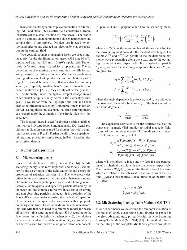
(p: parallel || and s: perpendicular � to the scattering plane)as
E
E
e
ikr
S S
S S
E
Es
s
ik r zi
i
||( )
||
�
�
�
���
�
��
���
����
2 3
4 1
�
, (1)
where k � 2� � is the wavenumber of the incident light inthe surrounding medium and � the incident wavelength. Thefactors e ikz� and e ikrikr � pertain to the incident plane har−monic wave propagating along the z axis and to the out−go−ing scattered wave respectively. For a spherical particleS S3 4 0� � and the scattering amplitude functions S S1 2, ,are given by
Sn
n na b
Sn
n na
nn n n n
n
11
21
2 1
1
2 1
1
� ��
�
� ��
�
�
�
�
( )( ),
( )(
� �
n n n nb� �� ),
(2)
where the angle dependent functions � n and � n are related tothe associated Legendre functions Pn
1 of the first kind of or−der 1 and degree n.
��
��n
nn
nP dP� �
1 1
sin,
sin. (3)
The expansion coefficients for the scattered field of thetransverse magnetic (TM) mode (no radial magnetic field)an and of the transverse electric (TE) mode (no radial elec−tric field) bn are given by Ref. 11
am mx x x mx
m mx x xnn n n n
n n n
�� � �� � �
� � � �� �
( ) ( ) ( ) ( )
( ) ( ) ( )� � n
nn n n n
n n
mx
bmx x m x mx
mx x m
( ),
( ) ( ) ( ) ( )
( ) ( )�
� � �� �
� � � �� � �n nx mx( ) ( )
,��
(4)
where m is the refractive index and x ka� is the size parame−ter of a spherical particle with the diameter a respectively.The functions �n ( )� , � �n ( ) are the Ricatti−Bessel functionswhich are related to the spherical Bessel functions of the firstkind jn ( )� and the spherical Hankel function of the first kindhn
( ) ( )1 � as
�n n
n n
j
h
( ) ( ),
( ) ( ).( )
� � �
� � � �
�
� 1(5)
3.2. Mie Scattering Lookup Table Method (MSLTM)
In our experiments we determine the temporal evolution ofthe radius of single evaporating liquid droplet suspended inthe electrodynamic trap, primarily with the Mie ScatteringLookup Table Method (MSLTM) [19]. Our method is basedon the fitting of the complete Mie theory predictions (stored
Optical diagnostics of a single evaporating droplet using fast parallel computing on graphics processing units
110 Opto−Electron. Rev., 24, no. 3, 2016 © 2016 SEP, Warsaw
UnauthenticatedDownload Date | 1/18/17 10:58 AM
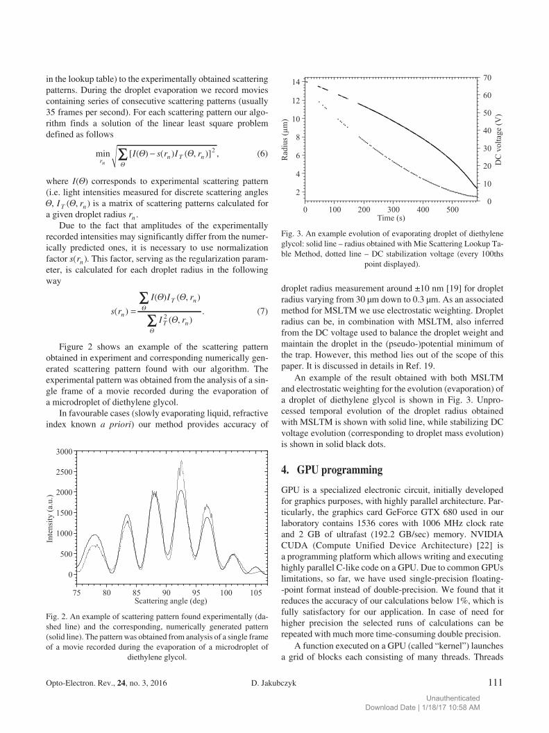
in the lookup table) to the experimentally obtained scatteringpatterns. During the droplet evaporation we record moviescontaining series of consecutive scattering patterns (usually35 frames per second). For each scattering pattern our algo−rithm finds a solution of the linear least square problemdefined as follows
min [ ( ) ( ) ( , )] ,r
n T nn
I s r I r
�� 2 (6)
where I( ) corresponds to experimental scattering pattern(i.e. light intensities measured for discrete scattering angles, I rT n( , ) is a matrix of scattering patterns calculated fora given droplet radius rn .
Due to the fact that amplitudes of the experimentallyrecorded intensities may significantly differ from the numer−ically predicted ones, it is necessary to use normalizationfactor s rn( ). This factor, serving as the regularization param−eter, is calculated for each droplet radius in the followingway
s r
I I r
I rn
T n
T n
( )
( ) ( , )
( , ).�
�
�
2(7)
Figure 2 shows an example of the scattering patternobtained in experiment and corresponding numerically gen−erated scattering pattern found with our algorithm. Theexperimental pattern was obtained from the analysis of a sin−gle frame of a movie recorded during the evaporation ofa microdroplet of diethylene glycol.
In favourable cases (slowly evaporating liquid, refractiveindex known a priori) our method provides accuracy of
droplet radius measurement around ±10 nm [19] for dropletradius varying from 30 μm down to 0.3 μm. As an associatedmethod for MSLTM we use electrostatic weighting. Dropletradius can be, in combination with MSLTM, also inferredfrom the DC voltage used to balance the droplet weight andmaintain the droplet in the (pseudo−)potential minimum ofthe trap. However, this method lies out of the scope of thispaper. It is discussed in details in Ref. 19.
An example of the result obtained with both MSLTMand electrostatic weighting for the evolution (evaporation) ofa droplet of diethylene glycol is shown in Fig. 3. Unpro−cessed temporal evolution of the droplet radius obtainedwith MSLTM is shown with solid line, while stabilizing DCvoltage evolution (corresponding to droplet mass evolution)is shown in solid black dots.
4. GPU programming
GPU is a specialized electronic circuit, initially developedfor graphics purposes, with highly parallel architecture. Par−ticularly, the graphics card GeForce GTX 680 used in ourlaboratory contains 1536 cores with 1006 MHz clock rateand 2 GB of ultrafast (192.2 GB/sec) memory. NVIDIACUDA (Compute Unified Device Architecture) [22] isa programming platform which allows writing and executinghighly parallel C−like code on a GPU. Due to common GPUslimitations, so far, we have used single−precision floating−−point format instead of double−precision. We found that itreduces the accuracy of our calculations below 1%, which isfully satisfactory for our application. In case of need forhigher precision the selected runs of calculations can berepeated with much more time−consuming double precision.
A function executed on a GPU (called “kernel”) launchesa grid of blocks each consisting of many threads. Threads
Opto−Electron. Rev., 24, no. 3, 2016 D. Jakubczyk 111
Fig. 2. An example of scattering pattern found experimentally (da−shed line) and the corresponding, numerically generated pattern(solid line). The pattern was obtained from analysis of a single frameof a movie recorded during the evaporation of a microdroplet of
diethylene glycol.
Fig. 3. An example evolution of evaporating droplet of diethyleneglycol: solid line – radius obtained with Mie Scattering Lookup Ta−ble Method, dotted line – DC stabilization voltage (every 100ths
point displayed).
UnauthenticatedDownload Date | 1/18/17 10:58 AM
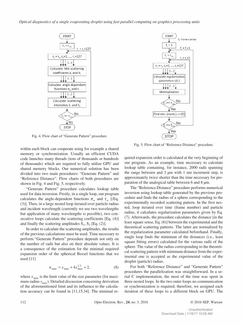
within each block can cooperate using for example a sharedmemory or synchronization. Usually an efficient CUDAcode launches many threads (tens of thousands or hundredsof thousands) which are required to fully utilize GPU andshared memory blocks. Our numerical solution has beendivided into two main procedures: “Generate Pattern” and“Reference Distance”. Flow charts of both procedures areshown in Fig. 4 and Fig. 5, respectively.
“Generate Pattern” procedure calculates lookup tableused for data inversion. Firstly, in a single loop, our programcalculates the angle−dependent functions � n and � n [(Eq.(3)]. Then, in a large nested loop iterated over particle radiusand incident wavelength (currently we use two wavelengthsbut application of many wavelengths is possible), two con−secutive loops calculate the scattering coefficients [Eq. (4)]and finally the scattering amplitudes S1, S2 [Eq. (2)].
In order to calculate the scattering amplitudes, the resultsof the previous calculations must be used. Time necessary toperform “Generate Pattern” procedure depends not only onthe number of radii but also on their absolute values. It isa consequence of the estimation for the minimal requiredexpansion order of the spherical Bessel functions that weused [11]
n x xmax max max ,� � �4 21 3 (8)
where x max is the limit value of the size parameter (for maxi−mum radius rmax). Detailed discussion concerning derivationof the aforementioned limit and its influence to the calcula−tion accuracy can be found in [11,15,34]. The minimal re−
quired expansion order is calculated at the very beginning ofour program. As an example, time necessary to calculatelookup table containing, for instance, 2000 radii spanningthe range between and 3 μm with 1 nm increment step, isapproximately twice shorter than the time necessary for pre−paration of the analogical table between 6 and 8 μm.
The “Reference Distance” procedure performs numericalinversion using lookup table generated by the previous pro−cedure and finds the radius of a sphere corresponding to theexperimentally recorded scattering pattern. In the first nes−ted, loop iterated over time (frame number) and particleradius, it calculates regularization parameters given by Eq.(7). Afterwards, the procedure calculates the distance [in theleast square sense, Eq. (6)] between the experimental and thetheoretical scattering patterns. The latter are normalized bythe regularization parameter calculated beforehand. Finally,single loop finds the minimum of the distances (i.e., leastsquare fitting errors) calculated for the various radii of thesphere. The value of the radius corresponding to the theoreti−cal scattering pattern with minimum distance from the exper−imental one is accepted as the experimental value of thedroplet (particle) radius.
For both “Reference Distance” and “Generate Pattern”procedures the parallelization was straightforward. In a se−rial C implementation, the most of the time was spent inthree nested loops. In the two outer loops no communicationor synchronization is required; therefore, we assigned eachiteration of these loops to a different block on GPU. The
Optical diagnostics of a single evaporating droplet using fast parallel computing on graphics processing units
112 Opto−Electron. Rev., 24, no. 3, 2016 © 2016 SEP, Warsaw
Fig. 4. Flow chart of “Generate Pattern” procedure.
Fig. 5. Flow chart of “Reference Distance” procedure.
UnauthenticatedDownload Date | 1/18/17 10:58 AM
third inner loop performs the reduction across an array (i.e.,sums the values into a common buffer). Because the commu−nication and synchronization is now required, we assignedall the computations to a single block, and used shared mem−ory to perform the reduction within the block. Benchmarksshowed that 128 is the optimal number of threads per blockfor both “Reference Distance” and “Generate Pattern”, the−refore each block processes data frames in chunks of 128.Maximal performance is achieved when the number of pro−cessed data frames is significantly larger than 128, mostlybecause in that case threads could efficiently add a lot of val−ues into a local buffer (stored in registers) and do an expen−sive reduction in shared memory only once at the end ofcomputation.
5. Results and discussion
For the numerical calculations we used C−like code runningon the NVIDIA GeForce GTX 680 graphics card. Computa−tional times have been compared with analogical code run−ning in Matlab environment (single−core implementation)and also with C−language code running on quad−core CPU.We tested both single−core and quad−core implementations.All the test calculations were performed on the up−to−datedesktop computer with Intel Core i7−3770K processor (3.40GHz clock rate), 16 GB RAM memory and NVIDIAGeForce GTX 680 graphics card.
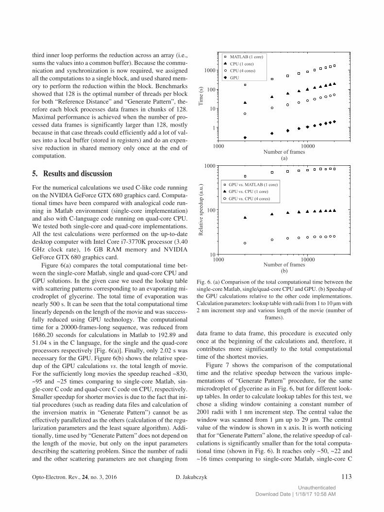
Figure 6(a) compares the total computational time bet−ween the single−core Matlab, single and quad−core CPU andGPU solutions. In the given case we used the lookup tablewith scattering patterns corresponding to an evaporating mi−crodroplet of glycerine. The total time of evaporation wasnearly 500 s. It can be seen that the total computational timelinearly depends on the length of the movie and was success−fully reduced using GPU technology. The computationaltime for a 20000−frames−long sequence, was reduced from1686.20 seconds for calculations in Matlab to 192.89 and51.04 s in the C language, for the single and the quad−coreprocessors respectively [Fig. 6(a)]. Finally, only 2.02 s wasnecessary for the GPU. Figure 6(b) shows the relative spee−dup of the GPU calculations vs. the total length of movie.For the sufficiently long movies the speedup reached ~830,~95 and ~25 times comparing to single−core Matlab, sin−gle−core C code and quad−core C code on CPU, respectively.Smaller speedup for shorter movies is due to the fact that ini−tial procedures (such as reading data files and calculation ofthe inversion matrix in “Generate Pattern”) cannot be aseffectively parallelized as the others (calculation of the regu−larization parameters and the least square algorithm). Addi−tionally, time used by “Generate Pattern” does not depend onthe length of the movie, but only on the input parametersdescribing the scattering problem. Since the number of radiiand the other scattering parameters are not changing from
data frame to data frame, this procedure is executed onlyonce at the beginning of the calculations and, therefore, itcontributes more significantly to the total computationaltime of the shortest movies.
Figure 7 shows the comparison of the computationaltime and the relative speedup between the various imple−mentations of “Generate Pattern” procedure, for the samemicrodroplet of glycerine as in Fig. 6, but for different look−up tables. In order to calculate lookup tables for this test, wechose a sliding window containing a constant number of2001 radii with 1 nm increment step. The central value thewindow was scanned from 1 μm up to 29 μm. The centralvalue of the window is shown in x axis. It is worth noticingthat for “Generate Pattern” alone, the relative speedup of cal−culations is significantly smaller than for the total computa−tional time (shown in Fig. 6). It reaches only ~50, ~22 and~16 times comparing to single−core Matlab, single−core C
Opto−Electron. Rev., 24, no. 3, 2016 D. Jakubczyk 113
Fig. 6. (a) Comparison of the total computational time between thesingle−core Matlab, single/quad−core CPU and GPU. (b) Speedup ofthe GPU calculations relative to the other code implementations.Calculation parameters: lookup table with radii from 1 to 10 μm with2 nm increment step and various length of the movie (number of
frames).
UnauthenticatedDownload Date | 1/18/17 10:58 AM
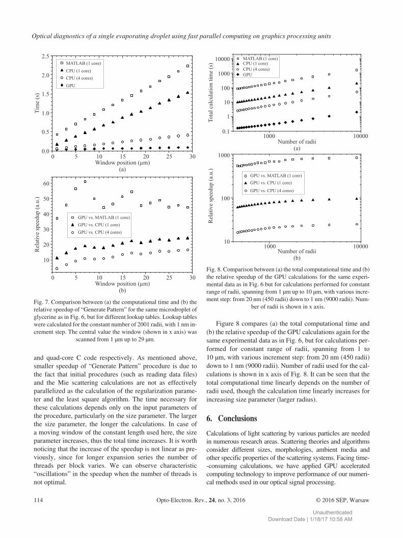
and quad−core C code respectively. As mentioned above,smaller speedup of “Generate Pattern” procedure is due tothe fact that initial procedures (such as reading data files)and the Mie scattering calculations are not as effectivelyparallelized as the calculation of the regularization parame−ter and the least square algorithm. The time necessary forthese calculations depends only on the input parameters ofthe procedure, particularly on the size parameter. The largerthe size parameter, the longer the calculations. In case ofa moving window of the constant length used here, the sizeparameter increases, thus the total time increases. It is worthnoticing that the increase of the speedup is not linear as pre−viously, since for longer expansion series the number ofthreads per block varies. We can observe characteristic“oscillations” in the speedup when the number of threads isnot optimal.
Figure 8 compares (a) the total computational time and(b) the relative speedup of the GPU calculations again for thesame experimental data as in Fig. 6, but for calculations per−formed for constant range of radii, spanning from 1 to10 μm, with various increment step: from 20 nm (450 radii)down to 1 nm (9000 radii). Number of radii used for the cal−culations is shown in x axis of Fig. 8. It can be seen that thetotal computational time linearly depends on the number ofradii used, though the calculation time linearly increases forincreasing size parameter (larger radius).
6. Conclusions
Calculations of light scattering by various particles are neededin numerous research areas. Scattering theories and algorithmsconsider different sizes, morphologies, ambient media andother specific properties of the scattering systems. Facing time−−consuming calculations, we have applied GPU acceleratedcomputing technology to improve performance of our numeri−cal methods used in our optical signal processing.
Optical diagnostics of a single evaporating droplet using fast parallel computing on graphics processing units
114 Opto−Electron. Rev., 24, no. 3, 2016 © 2016 SEP, Warsaw
Fig. 7. Comparison between (a) the computational time and (b) therelative speedup of “Generate Pattern” for the same microdroplet ofglycerine as in Fig. 6, but for different lookup tables. Lookup tableswere calculated for the constant number of 2001 radii, with 1 nm in−crement step. The central value the window (shown in x axis) was
scanned from 1 μm up to 29 μm.
Fig. 8. Comparison between (a) the total computational time and (b)the relative speedup of the GPU calculations for the same experi−mental data as in Fig. 6 but for calculations performed for constantrange of radii, spanning from 1 μm up to 10 μm, with various incre−ment step: from 20 nm (450 radii) down to 1 nm (9000 radii). Num−
ber of radii is shown in x axis.
UnauthenticatedDownload Date | 1/18/17 10:58 AM
We showed that GPU programming can be effectivelyapplied to inverse scattering problems. The calculations area part of the larger setup utilized for the characterization ofevaporating microdroplets. The recorded series of scatteringpatterns are processed by fitting complete Mie theory predic−tions with gradientless, lookup table method. Computationaldifficulties encountered during the experimental work wereassociated not with the algorithm complexity but with thenumber of iterations needed to obtain the entire temporalevolution of the droplet radius. Time necessary for both theMie scattering calculations and the data inversion with thelookup table method was significantly reduced. The totalspeedup for the favourable cases reached ~830, ~95 and ~25times comparing to single−core Matlab, single−core C andquad−core C code running on CPU, respectively. Addition−ally, we overcame problems of time−consuming data post−−processing when some of the parameters (particularly therefractive index) of an investigated liquid are uncertain.With GPU technology, we can easily iterate over the un−known parameter and find the best fit. Very effective para−llelization was possible since the calculations for consecu−tively recorded radii of an evaporating droplet (data frames)are independent. Data exchange was necessary only withinthe data frame. The ultimate goal was to write a programwhich from a human operator point of view displays resultsnearly instantly. For a moderate droplet size of few microm−eters, lookup table of 20−nm−step and up to ~300 data frames(usual display resolution) the goal can be considered asaccomplished. Faster GPUs can easily further reduce theconstraints.
Further improvements of our methods would be aimed atproviding solutions for more complex scattering problems.We would like to use different algorithms, such as modifica−tion of Mie theory for spheroids [35], T−Matrix method [36]and Discrete Dipole Approximation [37].
Acknowledgements
This work was supported by the National Science Centre,Poland under grants number 2014/13/D/ST3/01882 and2014/13/B/ST3/04414.
References
1. T. Nousiainen, “Optical modeling of mineral dust particles:A review”, J. Quant. Spectrosc. Radiat. Transfer 110,1261–1279 (2009).
2. T. Bond and R. Bergstrom, “Light absorption by carbona−ceous particles: an investigative review”, Aerosol Sci. Tech−nol. 40, 27–67 (2006).
3. F. Onofri, M. Woźniak, and S. Barbosa, “On the optical char−acterisation of nanoparticle and their aggregates in plasmasystems”, Contrib. Plasma Phys. 51, 228–236 (2011).
4. R. Hołyst, M. Litniewski, D. Jakubczyk, K. Kolwas, M. Kol−was, K. Kowalski, S. Migacz, S. Palesa, and M. Zientara,“Evaporation of freely suspended single droplets: experimen−tal, theoretical and computational simulations”, Rep. Prog.Phys. 76, 034601–034620 (2013).
5. G. Derkachov, K. Kolwas, D. Jakubczyk, M. Zientara, and M.Kolwas, “Drying of a microdroplet of water suspension ofnanoparticles: from surface aggregates to microcrystal”, J.Phys. Chem. C 112, 16919–16923 (2008).
6. G. Derkachov, D. Jakubczyk, M. Woźniak, J. Archer, and M.Kolwas, “High precision temperature determination of evap−orating light−absorbing and nonlight−absorbing droplets”, J.Phys. Chem. B 118, 12566–12574 (2014).
7. P.K. Jain, K.S. Lee, I.H. El−Sayed, and M.A. El−Sayed, “Cal−culated absorption and scattering properties of gold nanopar−ticles of different size, shape, and composition: applicationsin biological imaging and biomedicine”, J. Phys. Chem. B110, 7238–7248 (2006).
8. K. Kolwas, A. Derkachova, and D. Jakubczyk, “Tailoringplasmon resonances in metal nanospheres for optical diagnos−tics of molecules and cells”, in Nanomedicine and Tissue En−gineering, State of the Art and Recent Trends, Apple Aca−demic Press 2015.
9. K. Kolwas and A. Derkachova, “Plasmonic abilities of goldand silver spherical nanoantennas in terms of size dependentmultipolar resonance frequencies and plasmon damping ra−tes”, Opto−Electr. Rev. 18, 429–437 (2010),
10. M. Salerno, J.R. Krenn, B. Lamprecht, G. Schider, H. Ditl−bacher, N. Felidj, A. Leitner, and F.R. Aussenegg, “Plasmonpolaritons in metal nanostructures: the optoelectronic route tonanotechnology”, Opto−Electr. Rev. 10, 217–224 (2002).
11. C.F. Bohren and D.R. Huffman, Absorption and Scattering ofLight by Small Particles, Wiley−VCH, 2007.
12. D. Efremenko, D. Loyola, A. Doicu, and R. Spurr, “Multi−−core−cpu and gpuaccelerated radiative transfer models basedon the discrete ordinate method”, Comput. Phys. Commun.185, 3079–3089 (2014).
13. Y. Eremin and T. Wriedt, “New scheme of the discrete sour−ces method for light scattering analysis of a particle breakinginterface”, Comput. Phys. Commun. 185, 3141–3150 (2014).
14. G. Mie, Beiträge zur Optik trüber Medien, speziell kolloidalerMetallösugen, Ann. Phys. 330, 377–445 (1908). (IN GER−MAN).
15. W.J. Wiscombe, “Mie Scattering Calculations: Advances inTechnique and Fast, Vector−Speed Computer Codes”, NCARTechnical Note NCAR/TN−140+STR, National Center forAtmospheric Research, Boulder, Colorado. 80307, (1979).
16. H. Du, “Mie−scattering calculation”, Appl. Opt. 43, 1951–1956(2004).
17. J. Shen, “Algorithm of numerical calculation on Lorentz MieTheory”, PIERS Online 1, 691–694 (2005).
18. A. Gogoi, A. Choudhury, and G. Ahmed, “Mie scatteringcomputation of spherical particles with very large size param−eters using an improved program with variable speed and ac−curacy”, J. Mod. Opt. 57, 2192–2202 (2010).
19. D. Jakubczyk, G. Derkachov, M. Kolwas, and K. Kolwas,“Combining weighting and Scatterometry: application to a le−
Opto−Electron. Rev., 24, no. 3, 2016 D. Jakubczyk 115
UnauthenticatedDownload Date | 1/18/17 10:58 AM
vitated droplet of suspension”, J. Quant. Spectrosc. Radiat.Transfer 125, 99–104 (2013).
20. M. Kolwas, D. Jakubczyk, G. Derkachov, and K. Kolwas,“Interaction of optical Whispering Gallery Modes with thesurface layer of evaporating droplet of suspension”, J. Quant.Spectrosc. Radiat. Transfer 131, 138–145 (2013).
21. M. Kolwas, K. Kolwas, D. Jakubczyk, and G. Derkachov,“Surface diagnostics of evaporating droplet of nanospheressuspension; Fano interference and surface pressure”, Phys.Chem. Chem. Phys. 17, 6881–6888 (2015).
22. CUDA, CUDA Toolkit Documentation (2013). URL https://developer.nvidia.com/cuda−toolkit
23. D. Luebke, “CUDA: scalable parallel programming for high−−performance scientific computing”, 5th IEEE InternationalSymposium on Biomedical Imaging: From Nano to Macro,836–838 (2008).
24. Q. Nguyen, V. Dang, O. Kilic, and E. El−Araby, “Paralleli−zing Fast Multipole Method for large−scale electromagneticproblems using GPU clusters”, IEEE Antennas Wirel. Pro−pag. Lett. 12, 868–871 (2013).
25. G. Iadarola, C. Forestiere, L. Dal Negro, F. Villone, and G.Miano, “GPUaccelerated T−matrix algorithm for light−scat−tering simulations”, J. Comput. Phys. 231 5640–5652 (2012).
26. D. De Donno, A. Esposito, G.Monti, and L. Tarricone, “MPIE/MoMacceleration with a general−purpose graphics processingunit”, IEEE Trans. Microwave Theory Tech. 60, 2693–2701(2012).
27. S. Li, R. Chang, A. Boag, and V. Lomakin, “Fast Electromag−netic Integralequation Solvers on Graphics ProcessingUnits”, IEEE Antennas Propag. Mag. 54, 71–87 (2012).
28. E. Lezar and D. Davidson, “GPU acceleration of electromag−netic scattering analysis using the Method of Moments”, Int.Conf. Electromagnetics in Advanced Applications 60,452–455 (2011).
29. W. Sirignano, Fluid Dynamics and Transport of Droplets andSprays, Cambridge University Press 1999.
30. K. Yu, J. Yang, and Yi Y. Zuo, “Automated droplet manipu−lation using closed−loop axisymmetric drop shape analysis”,Langmuir 32, 4820−4826 (2016).
31. D. Jakubczyk, M. Zientara, K. Kolwas, and M. Kolwas,“Temperature dependence of evaporation coefficient for wa−ter measured in droplets in nitrogen under atmospheric pres−sure”, Atm. Sci. 64, 996–1004 (2007).
32. D. Duft, T. Achtzehn, R. Müller, B. Huber, and T. Leisner,“Rayleigh jets from levitated microdroplets”, Nature 421,128 (2003).
33. R. Xu, Particle Characterization: Light Scattering Methods,Kluwert Academic Publisher, New York, 2002.
34. W.J. Wiscombe, “Improved mie scattering algorithms”, Appl.Opt. 19, 1505–1509 (1980).
35. M. Quinten, Optical Properties of Nanoparticle Systems. Mieand Beyond, Wiley−VCH, 2011.
36. P. C. Waterman, “Matrix formulation of electromagnetic sca−ttering”, Proc. IEEE 53, 805–812 (1965).
37. B. Draine and P. Flatau, “Discrete−Dipole Approximation forscattering calculations”, J. Opt. Soc. Am. A 11 1491–1499(1994).
Optical diagnostics of a single evaporating droplet using fast parallel computing on graphics processing units
116 Opto−Electron. Rev., 24, no. 3, 2016 © 2016 SEP, Warsaw
UnauthenticatedDownload Date | 1/18/17 10:58 AM