OPERATOR’S AND PARTS MANUAL ATP46TP67 & A … · 800-456-7100 I 503 Gay Street, Delhi, IA 52223,...
37
800-456-7100 I www.paladinlcg.com 503 Gay Street, Delhi, IA 52223, United States of America SERIAL NUMBER: ___________________ Manual Number: OM651 Part Number: 75551 MODEL NUMBER: ___________________ Rev. 2 OPERATOR’S AND PARTS MANUAL ATP46 & ATP67 HYDRAULIC ANGLE AND TILT DOZER BLADE 9529 1-21-10-3
Transcript of OPERATOR’S AND PARTS MANUAL ATP46TP67 & A … · 800-456-7100 I 503 Gay Street, Delhi, IA 52223,...

800-456-7100 I www.paladinlcg.com 503 Gay Street, Delhi, IA 52223, United States of America
SERIALNUMBER:___________________ ManualNumber:OM651 PartNumber:75551 MODELNUMBER:___________________ Rev.2
OPERATOR’SANDPARTSMANUAL
ATP46&ATP67HYDRAULICANGLEANDTILT
DOZERBLADE
9529 1-21-10-3


TO THE OWNER .............................................................................................A
SAFETY PRECAUTIONS ................................................................................BGeneral InformationTo The OperatorBefore You StartWorking With The BladeTransporting the BladeMaintenance
INTERNATIONAL SYMBOLS .........................................................................C
PRE-OPERATION ...........................................................................................D
HYDRAULIC BLADE ASSEMBLY .................................................................. EBlade AssemblyCylinder AssembliesDual Auxiliary Hydraulic AssemblySelector Valve Hydraulic AssemblyElectric Solenoid Valve Hydraulic Assembly
INSTALLATION AND OPERATION ............................................................... GAttachingOperating InstructionsAngling and Tilting The BladeOperating TipsDetachingStorage
MAINTENANCE & SERVICE ........................................................................... LDailyEvery 40 HoursCylinder Seal Relacement
TROUBLESHOOTING.....................................................................................N
BOLT TORQUE .............................................................................................. O
SPECIFICATIONS ........................................................................................... P
DECALS.......................................................................................................... Q
LIMITED WARRANTY ..................................................................................... S
TABLE OF CONTENTS
95383-31-04

THIS PAGEIS INTENTIONALLY
BLANK

TO THE OWNERAA
89153-5-03
GENERAL COMMENTS
Congratulations on the purchase of your new BRADCO product! Thisproduct was carefully designed and manufactured to give you years of dependableservice. Only minor maintenance (such as cleaning and lubricating) is required tokeep it in top working condition. Be sure to observe all safety precautions andmaintenance procedures, as described in this manual.
ABOUT THIS MANUAL
This manual has been designed to help you do a better, safer job. Read thismanual carefully and become familiar with its contents. Remember, never letanyone operate this unit without reading the "Safety Precautions" and"Operating Instructions" sections of this manual. (See Sections B and Grespectively.)
Unless noted otherwise, right and left sides are determined from the positionof the operator when behind the product facing forward.
SAFETY ALERT SYMBOL
This is the "Safety Alert Symbol" used by this industry. This symbol isused to warn of possible injury. Be sure to read all warnings carefully.They are included for your safety and for the safety of others workingwith you.
SERVICE
When servicing your product, remember to use only manufacturer replace-ment parts. Substitute parts may not meet the standards required for safe, depend-able operation.
To facilitate parts ordering, record the model and serial number of your unit inthe space provided on this page. This information may be obtained from the identi-fication plate located on the product.
MODEL____________________________________SERIAL NUMBER___________________________DATE PURCHASED_________________________
The parts department needs this information to insure that you receive thecorrect parts for your specific model.

THIS PAGEIS INTENTIONALLY
BLANK

SAFETY PRECAUTIONSB B
TAKE NOTE! THIS SAFETY ALERT SYMBOL FOUND THROUGHOUT THISMANUAL IS USED TO CALL YOUR ATTENTION TO INSTRUCTIONS IN-VOLVING YOUR PERSONAL SAFETY OR OTHERS. FAILURE TO FOLLOWTHESE INSTRUCTIONS CAN RESULT IN INJURY OR DEATH.
THIS SYMBOL MEANS:
ATTENTION!
BECOME ALERT!
YOUR SAFETY IS INVOLVED!
SIGNAL WORDS: Note the use of signal words DANGER, WARNING, and CAU-TION with the safety messages. The appropriate signal word for each has beenselected using the following guidelines:
DANGER: Indicates an imminently hazardous situation, which if not avoided, willresult in death or serious injury. This signal word is to be limited to themost extreme situations, typically for machine componentswhich, for functional purposes, cannot be guarded.
WARNING: Indicates a potentially hazardous situation, which if not avoided, couldresult in death or serious injury, and includes hazards that areexposed when guards are removed. It may also be used toalert against unsafe practices.
CAUTION: Indicates a potentially hazardous situation, which if not avoided, mayresult in minor or moderate injury. It may also be used to alertagainst unsafe practices.
66215-18-95

SAFETY PRECAUTIONSBB
89474-8-05-2
GENERAL INFORMATIONThis section is composed of various warnings and safety tips. Read and learn
all the information in this section before you attempt to use your blade. Alsoread your loader owner's manual before using your equipment. This knowledge will helpyou operate your unit safely. Do not take this information lightly, it is presented foryour own benefit and for the benefit of others working around you.
The "Safety Alert Symbol", as previously described, will be used throughout thismanual. It will appear with the word DANGER, WARNING, or CAUTION above it, anda safety message pertaining to the specific topic being covered. Take the time to readthese messages as you come across them.
TO THE OPERATORThe primary responsibility for safety with the equipment falls to the operator.
Make sure that the equipment is operated only by responsible individuals with the properinstruction. It is the skill, care, common sense, and good judgment of the operator thatwill determine how efficiently and safely the job is performed. Know your equipmentbefore you start. Know its capabilities, dimensions, and how to operate all the controls.Visually inspect your equipment before you start, and never operate equipment that isnot in proper working order.
BEFORE YOU START1. Read the entire loader and attachment operator's manuals before ever
attempting to use the loader. This knowledge is necessary for safe operation.2. Follow all safety decals. Keep them clean and replace them if they become
worn and hard to read.3. Do not paint over, remove, or deface any safety signs or warning decals on
your equipment.4. Know your equipment inside and out. Know how to operate all controls, and
know emergency shut down procedures.5. Keep all stepping surfaces, pedals, and controls free from dirt, grease,
and oil. Keep equipment clean to help avoid injury from a fall when getting on oroff equipment.
6. Use handholds and step plates when getting on/off the skid-steer. Failureto do so could cause a fall.
7. Be alert to others in the work area. Be sure others know when and where youwill be working. Make sure no one is behind equipment.
8. Never take passengers on your equipment. There is no safe place for apassenger.

SAFETY PRECAUTIONSBB
89483-12-03
9. Never try to board equipment while it is moving.10. Turn off engine before performing maintenance. If lift arms must be left
raised for maintenance or any other reason, use a positive lift arm lock to se-cure the arms in place. Serious damage or personal injury could result from liftarms accidentally lowering.
11. Reduce speed when driving over rough terrain, on a slope, or turning, toavoid overturning the loader.
12. Test all controls before you begin.13. Do not smoke when refueling. Allow room in the gas tank for expansion.
Wipe up any spilt fuel. Secure cap tightly when done.
WORKING WITH THE BLADE1. Never operate the blade without first understanding the operator's
manual.2. Do not lift or carry people on the blade; they could fall and be crushed.3. Check your work area and know where all utility lines are. Avoid hitting
underground electrical wires, cables, pipes, fence posts, gas lines, unevensidewalk edges, large rocks, etc.
4. Never operate equipment while under the influence of alcohol or prescrip-tion drugs, which could inhibit physical and/or mental capacity.
5. Use for blade only for its designed purpose. Do not use it to pull objects,as a battering ram, or attach ropes or chains to the unit.
6. Never work under a raised blade.7. Do not push loads or objects in excess of loader/blade capacity.8. Always lower the loader arms and blade to the ground, shut off the engine,
and apply the parking brake before getting off the unit.
TRANSPORTING THE BLADE1. Follow all federal, state, and local regulations when transporting the unit
on public roads.
2. Carry blade low when transporting to lower its center of gravity. Useextra care when loading or unloading the machine onto a trailer or truck.
MAINTENANCE1. Never work on equipment while it is running. Set brake and lower blade
before performing repairs.2. Never make hydraulic repairs while the system is under pressure, or the
cylinders are under load. Injury or death could result.
SAFETY PRECAUTIONSBB
89193-5-03
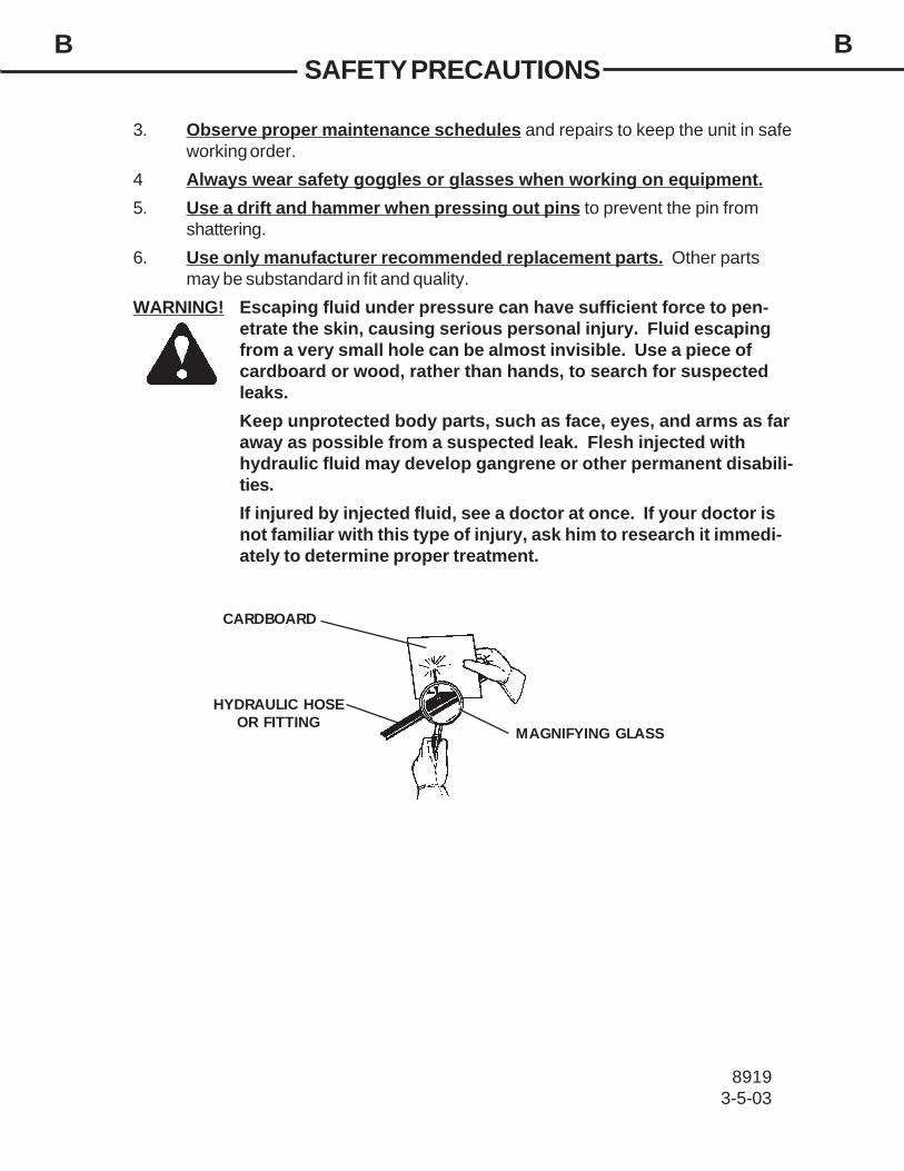
3. Observe proper maintenance schedules and repairs to keep the unit in safeworking order.
4 Always wear safety goggles or glasses when working on equipment.5. Use a drift and hammer when pressing out pins to prevent the pin from
shattering.6. Use only manufacturer recommended replacement parts. Other parts
may be substandard in fit and quality.WARNING! Escaping fluid under pressure can have sufficient force to pen-
etrate the skin, causing serious personal injury. Fluid escapingfrom a very small hole can be almost invisible. Use a piece ofcardboard or wood, rather than hands, to search for suspectedleaks.Keep unprotected body parts, such as face, eyes, and arms as faraway as possible from a suspected leak. Flesh injected withhydraulic fluid may develop gangrene or other permanent disabili-ties.If injured by injected fluid, see a doctor at once. If your doctor isnot familiar with this type of injury, ask him to research it immedi-ately to determine proper treatment.
CARDBOARD
HYDRAULIC HOSEOR FITTING
MAGNIFYING GLASS

C CINTERNATIONAL SYMBOLS
As a guide to the operation of your equipment, various internationalsymbols have been utilized on the instruments and controls. The symbolsare shown below with an indication of their meaning.
Engine speed Alternator charge
Hours recorded Power take-off (on)
Engine water temperature Power take-off (off)
Lights "Tortoise," slow or minimum setting
Horn "Hare," fast or maximum setting
Engine oil pressure Caution
Hazard warning Control lever operating direction
Axle connect Rock shaft (raised)
Axle disconnect Rock shaft (lowered)
Continuously variable Remote cylinder (extended)
Increase Remote cylinder (retracted)
Decrease Remote cylinder (FLOAT)
Diesel fuel Differential lock
Creeper range Read operators manual
High range Neutral
Low range Forward
Reverse
38694-14-94-2

THIS PAGEIS INTENTIONALLY
BLANK

PREOPERATIONHYDRAULIC BLADE
DD
95303-26-04
GENERAL INFORMATIONThe BRADCO hydraulic angle and tilt blades were designed to be easy to use
and maintain. There are three different hydraulic kits available: dual auxiliary hydraulics,selector valve, and electrical solenoid valve kit. They are all operated by the loadersauxiliary hydraulics and the blade mounts to the toolbar / quick attach mechanism foreasy mounting.
Unless noted otherwise, right and left are determined from the position of theoperator facing forward.
Remember to read the "Safety Precautions" and "Operating Instructions" sec-tions of this manual BEFORE you attempt to install or use the attachment.
NOTE: The illustrations and data used in this manual were current (accordingto the information available to us) at the time of printing, however, we reservethe right to redesign and change the tillers as may be necessary without notifi-cation.
BEFORE OPERATIONThe primary responsibility for safety with this equipment falls to the operator.
Make sure that the equipment is operated only by trained individuals that have read andunderstand this manual.
If there is any portion of this manual or function you do not understand, contactyour local authorized dealer or the manufacturer.
NOMENCLATUREThroughout this manual, reference is made to various blade components. Study
the following diagram to acquaint yourself with the various names of these components.This knowledge will be helpful when reading through this manual or when orderingservice parts.
BLADE
PIVOT FRAME(INCLUDES MOUNTING)
LEFT SIDE
RIGHT SIDE
CUTTINGEDGE
HYDRAULIC TILTCYLINDER
HOSE GUIDE
HYDRAULIC ANGLECYLINDER
TILT FRAME

HYDRAULIC BLADE ASSEMBLYHYDRAULIC ANGLE BLADE WITH TILT
EE
95213-24-04
1
2
3
4
56
789
10
11
12
13
1415
16
17
18
19
20
2
5
5
55
5
20
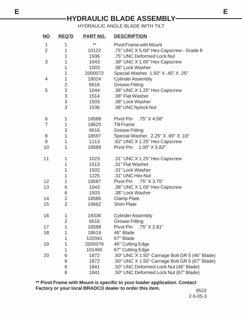
NO REQ'D PART NO. DESCRIPTION
1 1 ** Pivot Frame with Mount2 1 10122 .75" UNC X 5.00" Hex Capscrew - Grade 8
1 1936 .75" UNC Deformed Lock Nut3 1 1043 .38" UNC X 1.00" Hex Capscrew
1 1503 .38" Lock Washer1 2000072 Special Washer 1.50" X .45" X .25"
4 1 18024 Cylinder Assembly2 6616 Grease Fitting
5 3 1044 .38" UNC X 1.25" Hex Capscrew3 1514 .38" Flat Washer3 1503 .38" Lock Washer3 1536 .38" UNC Nylock Nut
6 1 19588 Pivot Pin .75" X 4.58"7 1 18620 Tilt Frame
3 6616 Grease Fitting8 1 18597 Special Washer 2.25" X .69" X .19"9 1 1113 .62" UNC X 1.25" Hex Capscrew
10 1 18589 Pivot Pin 1.00" X 5.82"
11 1 1023 .31" UNC X 1.25" Hex Capscrew1 1513 .31" Flat Washer1 1502 .31" Lock Washer1 1225 .31" UNC Hex Nut
12 1 18587 Pivot Pin .75" X 3.75"13 6 1043 .38" UNC X 1.00" Hex Capscrew
6 1503 .38" Lock Washer14 2 18586 Clamp Plate15 2 19662 Shim Plate
16 1 19336 Cylinder Assembly2 6616 Grease Fitting
17 1 18588 Pivot Pin .75" X 2.81"18 1 18619 46" Blade
1 102041 67" Blade19 1 2005076 46" Cutting Edge
1 101460 67" Cutting Edge20 6 1872 .50" UNC X 1.50" Carriage Bolt GR 5 (46" Blade)
8 1872 .50" UNC X 1.50" Carriage Bolt GR 5 (67" Blade)6 1841 .50" UNC Deformed Lock Nut (46" Blade)8 1841 .50" UNC Deformed Lock Nut (67" Blade)
HYDRAULIC BLADE ASSEMBLYHYDRAULIC ANGLE BLADE WITH TILT
EE
95222-5-05-3
** Pivot Frame with Mount is specific to your loader application. ContactFactory or your local BRADCO dealer to order this item.
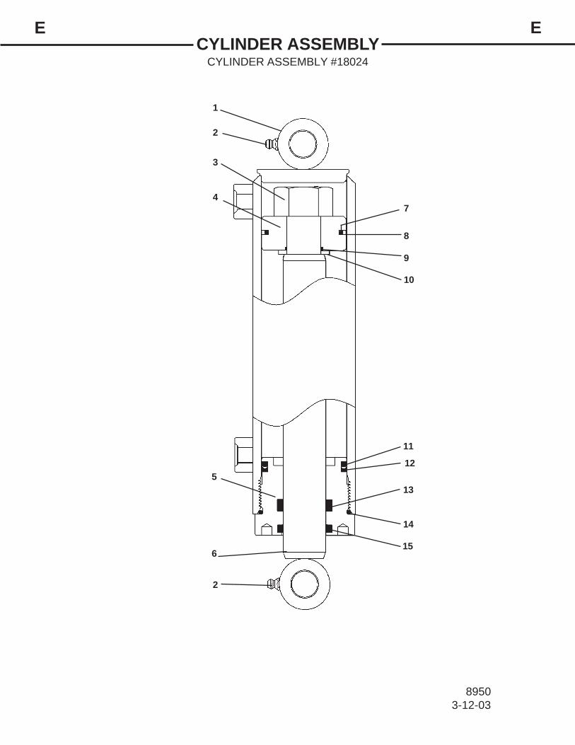
CYLINDER ASSEMBLYCYLINDER ASSEMBLY #18024
EE
89503-12-03
1
3
4
5
6
7
8
9
10
11
12
13
14
2
2
15

NO REQ'D PART NO. DESCRIPTION
1 1 18026 Cylinder Tube2 2 6616 Grease Fitting3 1 1483 Lock Nut4 1 50252 Piston5 1 77458 Cylinder Gland
6 1 18025 Cylinder Rod7 1 4645* O-Ring8 1 4644* Piston Ring9 1 4641* O-Ring
10 1 5421 Washer
11 1 4509* O-Ring12 1 4510* Back-Up Washer13 1 45219* Poly-Pak Seal14 1 45250 O'Ring15 1 45389* Rod Wiper
CYLINDER ASSEMBLYCYLINDER ASSEMBLY #18024
EE
89513-12-03
NOTE: Seal kit #45617 includes all parts marked with an asterisk (*). Partare not sold separately.

CYLINDER ASSEMBLYCYLINDER ASSEMBLY #19336
EE
95313-29-04
1
2
3
4
5
6
7
8
9
10
11
12
13
14
15
2

NO REQ'D PART NO. DESCRIPTION
1 1 19337 Cylinder Tube2 2 6616 Grease Fitting3 1 1483 Hex Nut4 1 50252 Piston5 1 77458 Cylinder Gland
6 1 19338 Cylinder Rod7 1 4645* O-Ring8 1 4644* Piston Ring9 1 4641* O-Ring
10 1 5421 Washer
11 1 4509* O-Ring12 1 4510* Back-Up Washer13 1 45219* Poly-Pak Seal14 1 45250* O-Ring15 1 45389* Rod Wiper
CYLINDER ASSEMBLYCYLINDER ASSEMBLY #19336
EE
95323-29-04
NOTE: Seal kit #45617 includes all parts marked with an asterisk (*). Partsare not sold separately.

HYDRAULIC ASSEMBLYDUAL AUXILIARY HYDRAULIC ASSEMBLY
EE
95233-26-04
TILT CYLINDER
ANGLE CYLINDER
TO LOADER AUXILIARYHYDRAULICS
TO LOADER AUXILIARYHYDRAULICS
1 2
1 2
3
3
4
56
5
6
7

NO REQ'D PART NO. DESCRIPTION
1 2 ** Male Coupler2 2 ** Female Coupler3 4 3269 Straight Connector 8MBo-6MJ4 2 37263 Hose Assembly .25" x 48" 6FJX - 6FJX5 2 14067 90° Elbow 6MBo-6MJ with .027 Orifice
6 2 3434 90° Elbow 6MBo-6MJ7 2 37575 Hose Assembly .25" x 53" 6FJX - 6FJX
HYDRAULIC ASSEMBLYDUAL AUXILIARY HYDRAULIC ASSEMBLY
EE
95243-26-04
** Hydraulic couplers are specific to your loader application. ContactFactory or your local BRADCO dealer to order these items.

HYDRAULIC ASSEMBLYSELECTOR VALVE HYDRAULIC ASSEMBLY
EE
95253-26-04
1
3
4
56
2
2
2
43
9
10
5
6
7
8
11
TILT CYLINDER
ANGLE CYLINDER
MOUNT TOLOADER ARM

NO REQ'D PART NO. DESCRIPTION
1 1 88953 Selector Valve2 6 30142 90° Elbow 8MBo-6MJ3 2 35692 Hose .25" X 103" 6JFX-6FJX4 2 37442 Hose .25" X 92" 6JFX-6FJX5 2 14067 90° Elbow 6MBo-6MJ with .027 Orifice
6 2 3434 90° Elbow 6MBo-6MJ7 6' 34052 Hose Sock (For Cylinder Hoses)8 2 35875 Hose Assembly .25" X 60" 6FJX-6FJX9 2 3269 Straight Connector 8MBo-6MJ
10 1 ** Female Coupler
11 1 ** Male Coupler
HYDRAULIC ASSEMBLYSELECTOR VALVE HYDRAULIC ASSEMBLY
EE
95263-26-04
** Hydraulic couplers are specific to your loader application. ContactFactory or your local BRADCO dealer to order these items.
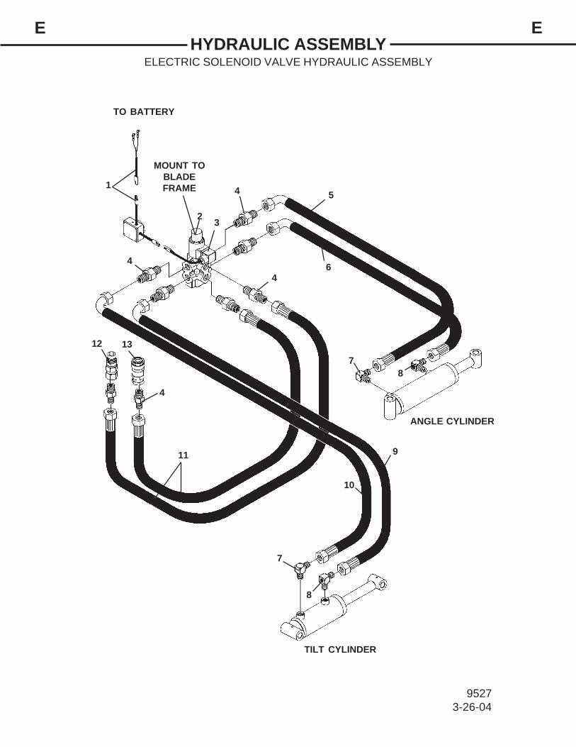
HYDRAULIC ASSEMBLYELECTRIC SOLENOID VALVE HYDRAULIC ASSEMBLY
EE
95273-26-04
1
2 3
4 5
6
78
9
10
11
12 13
7
8
TILT CYLINDER
TO BATTERY
ANGLE CYLINDER
4
4
4
MOUNT TOBLADEFRAME

NO REQ'D PART NO. DESCRIPTION
1 1 15757 Electrical Wire Control Harness2 1 19687 Solenoid Valve
2 1007 .25" UNC X 2.00" Hex Capscrew2 1501 .25" Lock Washer2 1224 .25" UNC Hex Nut
3 1 85386 DIN Connector4 8 30324 Straight Connector 8MBo-6MFS5 1 38130 Hose Assembly .25" x 18" 6FFS-6FFS 90°
6 1 38131 Hose Assembly .25" x 22.50" 6FFS-6FFS 90°7 2 30204 90° Elbow 6MBo-6MFS8 2 30209 90° Elbow 6MBo-6MFS with .027 Orifice9 1 38189 Hose Assembly .25" x 16" 6FFS-6FFS 90°
10 1 38192 Hose Assembly .25" x 19" 6FFS-6FFS 90°
11 2 38132 Hose Assembly .25" x 48" 6FFS-6FFS12 1 ** Male Coupler13 1 ** Female Coupler
HYDRAULIC ASSEMBLYELECTRIC SOLENOID VALVE HYDRAULIC ASSEMBLY
EE
95283-26-04
** Hydraulic couplers are specific to your loader application. ContactFactory or your local BRADCO dealer to order these items.

INSTALLATION AND OPERATIONGG
95333-29-04
ATTACHINGYour blade was shipped complete with the appropriate mounting for your specific
unit, and the hydraulic hoses and couplers were installed for the kit you ordered.Install the blade by following your power unit operator's manual for installing an
attachment.
WARNING! To Avoid Serious Personal Injury, make sure the blade is securelylatched to the attachment mechanism of your unit. Failure to do socould result in separation of the bucket from the unit.
If using the selector valve hydraulic kit, mount the selector valve to the arm of theloader. If powering the blade with the electrical solenoid valve hydraulic kit, connect theelectrical wire harness to the battery of the skid-steer, and position the control box in alocation accessible by the operator. Connect the hydraulic quick couplers to the auxiliaryhydraulics, and route the hoses in such a fashion as to prevent chafing and pinching.
WARNING! When working around batteries, remember that all of the exposedmetal parts are "live". Never lay a metal object across the terminals,because a spark or short circuit may result.
DANGER! BATTERY ACID CAUSES SEVERE BURNS. Batteries containsulfuric acid. Avoid contact with skin, eyes, or clothing.Antidote: EXTERNAL - flush with water. INTERNAL - drink largequantities of water or milk. Follow with milk of magnesia, beaten eggor vegetable oil. Call physician immediately. EYES - flush with waterfor 15 minutes and get prompt medical attention.
Start engine and slowly cycle the cylinders several times to purge system of airand check for proper hydraulic connection, hose routing, and hose length.
Check the attachment for proper assembly, installation, and hydraulic leaks.
OPERATING INSTRUCTIONSSimplicity of operation is one of the key features of the BRADCO blades.
There are only a few controls that affect the blade. It is important however, to be familiarwith, and know the controls and adjustments on both the blade and loader.
The blade mounts to the quick attach mechanism of your loader. Due to thisarrangement, thorough knowledge of the loader controls is necessary for bladeoperation. Read your loader operator's manual for information regarding loaderoperation before attempting to use the blade.
ANGLING AND TILTING THE BLADEThe blade is angled and tilted hydraulically by cylinders connected from the
blade to the pivot frame and tilt frame. The blade can be angled 35° left or right.The angle and tilt cylinders are activated by the auxiliary hydraulic system
controls. If using the selector valve, the position of the valve handle determines thecylinder being activated. If using the electric solenoid valve, the cylinder beingactivated is determined by the toggle switch on the control box.

INSTALLATION AND OPERATIONGG
95343-29-04
CAUTION! Drive slowly and with caution when operating the blade. Theforce of the impact if the blade hits an immovable object couldcause damage to the blade and loader, and injury to the operator.
OPERATING TIPSClean the area of trash, branches, and rocks before operation to prevent equip-
ment damage.Always begin with the slowest ground speed possible. Increase speed if
surrounding conditions permit.Always use full throttle (maximum engine speed).When leveling, scraping, and surface stripping, lower the cutting edge to the
ground, the blade will bite into the ground as you move forward.Watch for holes, rocks, or other hidden hazards. Always inspect area prior to
operation.
DETACHING
On firm level ground, lower the boom arms completely down on the frame untilthe blade is level and approximately 2" off the ground.
Turn off the engine. Move the control levers back and forth to relieve pressurein line. Disconnect couplers. NOTE: If using the electrical solenoid valve, disconnectthe wire harness coming from the battery to the control box, and attach the control box ontothe blade assembly.
NOTE: Connect couplers together or install caps to prevent contaminants fromentering the hydraulic system.
Follow your power unit operator's manual for detaching (removing) an attach-ment.
NOTE: Frequent lubrication of grease fittings at the end of the cylinder and pivotpoints with a multi-purpose grease will greatly increase life of the product.
STORAGE1. Clean the unit thoroughly, removing all mud, dirt, and grease.2. Inspect for visible signs of wear, breakage, or damage. Order any parts required,
and make the necessary repairs or avoid delays when starting next season.3. Tighten loose nuts, capscrews, and hydraulic connections.4. Cap hydraulic couplers to protect against contaminates.5. Touch up all unpainted surfaces with paint to prevent rust.6. Coat the exposed portions of the cylinder rods with grease.7. Store the unit in a dry and protected place. Leaving the unit outside will materially
shorten its life.

MAINTENANCE & SERVICELL
89213-5-03
GENERAL INFORMATIONRegular maintenance is the key to long equipment life and safe operation.
Maintenance requirements have been reduced to the absolute minimum. However,it is very important that these maintenance functions be performed as describedbelow.
DAILY• Check all bolts and nuts for tightness.• Replace any missing bolts or nuts with approved replacement parts.• Check hydraulic system for hydraulic oil leaks. See procedure below.• Visually inspect the machine for worn parts or cracked welds, and repair
as necessary.
EVERY 40 HOURS• Lubricate all grease fittings.
WARNING! Escaping fluid under pressure can have sufficient force to pen-etrate the skin, causing serious personal injury. Fluid escapingfrom a very small hole can be almost invisible. Use a piece ofcardboard or wood, rather than hands, to search for suspectedleaks.
Keep unprotected body parts, such as face, eyes, and arms asfar away as possible from a suspected leak. Flesh injectedwith hydraulic fluid may develop gangrene or other permanentdisabilities.
If injured by injected fluid, see a doctor at once. If your doctoris not familiar with this type of injury, ask him to research itimmediately to determine proper treatment.
CARDBOARD
HYDRAULIC HOSEOR FITTING
MAGNIFYING GLASS
IMPORTANT: When replacing parts, use only factory approved replacementparts. Manufacturer will not claim responsibility for use of unapprovedparts or accessories, and/or other damages as a result of their use.

MAINTENANCECYLINDER SEAL REPLACEMENT
LL
876210-3-02
ASSEMBLY PROCEDUREIMPORTANT: Replace all seals even if they do notappear to be damaged. Failure to replace all seals mayresult in premature cylinder failure.
1. Install the cylinder rod seal in the gland first. Becareful not to damage the seal in the process as it issomewhat difficult to install.
A special installation tool (Part #65349) is available tohelp with installing the seal. Simply fit the end of the toolover the seal so that the large prong of the tool is on theoutside of the seal, and the two smaller prongs on theinside. The lip of the seal should be facing towards thetool.
Rotate the handles on the tool around to wrap the sealaround the end of the tool.
Now insert the seal into the gland from the inner end.Position the seal in it's groove, and release and removethe tool. Press the seal into its seat the rest of the wayby hand.
2 . Install the new piston ring, rod wiper, O-ringsand backup washers if applicable on the piston.
Be careful not to damage the seals. Caution must beused when installing the piston ring. The ring must bestretched carefully over the piston with a smooth, round,pointed tool.
DISASSEMBLY PROCEDUREIMPORTANT: Do not contact the active surface of thecylinder rod with the vise. Damage to the rod couldresult.
THREADED TYPE GLAND1. Rotate the gland with a spanner wrench counter-clockwise until the gland is free of the cylinder tube.
2 . Pull the cylinder rod from the cylinder tube.
3 . Inspect the piston and the bore of the cylindertube for deep scratches or galling. If damaged, thepiston and cylinder tube must be replaced.
4 . Remove the hex nut, piston, flat washer orspacer tube (if so equipped), and gland from the cylinderrod. If the cylinder rod is rusty, scratched, or bent, itmust be replaced.
5 . Remove and discard all the old seals.
CYLINDER SEAL REPLACEMENTGENERAL INFORMATION
The following information is provided to assistyou in the event you should need to repair or rebuild ahydraulic cylinder. When working on hydraulic cylin-ders, make sure that the work area and tools are cleanand free of dirt to prevent contamination of the hydrau-lic system and damage to the hydraulic cylinders.Always protect the active part of the cylinder rod (thechrome section). Nicks or scratches on the surface ofthe rod could result in cylinder failure. Clean all partsthoroughly with a cleaning solvent before reassembly.

MAINTENANCECYLINDER SEAL REPLACEMENT
LL
3 . After installing the rod seal inside the gland asshown in step #1, install the external seal.
NOTE: Threaded glands may have been equipped witha separate O-ring and backup washer system or apolypak (all in one) type seal. Current seal kits containa polypak (all in one) type seal to replace the discardedseal types on ALL THREADED GLANDS.
4 . Slide the gland onto the cylinder rod beingcareful not to damage the rod wiper. Then install thespacer, or flat washer (if so equipped), small o-ring,piston, and hex nut onto the end of the cylinder rod.
5 . Secure the cylinder rod (mounting end) in a visewith a support at it’s center. Torque the nut to theamount shown for the thread diameter of the cylinderrod (see chart).
IMPORTANT: Do not contact the active surface of thecylinder rod with the vise. Damage to the rod couldresult.
6 . Apply a lubricant (such as Lubriplate #105) to thepiston and teflon ring. Insert the cylinder rod assemblyinto the cylinder tube.
IMPORTANT: Ensure that the piston ring fits squarelyinto the cylinder tube and piston groove, otherwise thering may be damaged and a leak will occur.
7 . Use a spanner wrench to rotate the gland clock-wise into the cylinder. Continue to rotate the gland withthe spanner wrench until it is tight.
NOTE: Seal kits will service most cylinders of similarbore size and rod diameter.
WARNING! Cylinders serviced in the field are to betested for leakage prior to the attach-ment being placed in work. Failure totest rebuilt cylinders could result indamage to the cylinder and/or the at-tachment, cause severe personal injuryor even death.
TORQUE SPECIFICATION CHART Use the following torque values when tighteningthe nuts on the cylinder rod threads.
ThreadDiameter Minimum Maximum
7/8" 150 200
* 1 " 230 325
1-1/8" 350 480
1-1/4" 490 670
1-3/8" 670 900
POUNDS - FEET
* 1" Thread Diameter WITH 1.25" Rod DiameterMin. 230 ft. lbs. Max. 250 ft. lbs.
876310-3-02

TROUBLESHOOTINGNN
95353-30-04
PROBLEM POSSIBLE CAUSE REMEDY
Blade fails to angle ortilt.
Obstruction in hydraulicline.
Hydraulic couplers notcompletely connected.
Hydraulic couplersmalfunctioning or non-compatible.
Defective hydrauliccylinder.
Remove obstruction orreplace.
Check and tighten cou-plers.
Replace.
Replace cylinder.
Blade angling or tiltingtoo slowly.
Cold oil.
Engine speed too slow.
Oil leaking past cylinderpackings.
Restriction in valve. (Ifso equipped.)
Warm oil with engine atidle.
Open throttle.
Replace cylinder seals.
Blade fails to maintainangle or tilt.
Broken or leaking hy-draulic lines.
Oil leaking past cylinderpackings.
Internal leak in valve. (Ifso equipped.)
Replace broken hose andcheck for leaks.
Replace cylinder seals.
Clean or replace.
External leaking. Cylinder seals dam-aged.
Broken or loose hydrau-lic fittings or line.
Spool in valve leaking.
Replace and Repair.
Check for leaks andrepair or replace.
Replace seals.
Clean or replace.
Blade functions in onecircuit only.
No electrical power tothe blade solenoidvalve. (If so equipped.)
Selector valve set toopposite operation. (Ifso equipped.)
Check for proper connec-tion in control box andpower from skid-steer.
Position selector valve tocorrect operation.
Blade functions in onecircuit only WITHpower to the solenoidvalve.
Blade valve malfunc-tioning.
Spool in valve sticking.
Replace and Repair.
Clean or Replace.

O O BOLT TORQUE
BOLT TORQUE SPECIFICATIONS
GENERAL TORQUE SPECIFICATION TABLE Use the following torques when special torques are not given. These values apply to fasteners as received from suppliers, dry, or when lubricated with normal engine oil. They do not apply if special graphited or moly disulphide greases or other extreme pressure lubricants are used. This applies to both UNF and UNC threads. Remember to always use grade five or better when replacing bolts.
SAE Grade No. 2 5 8* Bolt head identification marks as per grade. NOTE: Manufacturing Marks Will Vary
TORQUE TORQUE TORQUE
Bolt Size
Pounds Feet
Newton-Meters
Pounds Feet
Newton-Meters
Pounds Feet
Newton-Meters Inches Millimeters Min. Max. Min. Max. Min. Max. Min. Max. Min. Max. Min. Max.
1/4 6.35 5 6 6.8 8.13 9 11 12.2 14.9 12 15 16.3 30.3 5/16 7.94 10 12 13.6 16.3 17 20.5 23.1 27.8 24 29 32.5 39.3 3/8 9.53 20 23 27.1 31.2 35 42 47.5 57.0 45 54 61.0 73.2
7/16 11.11 30 25 40.7 47.4 54 64 73.2 86.8 70 84 94.9 113.9 1/2 12.70 45 52 61.0 70.5 80 96 108.5 130.2 110 132 149.2 179.0
9/16 14.29 65 75 88.1 101.6 110 132 149.2 179.0 160 192 217.0 260.4 5/8 15.88 95 105 128.7 142.3 150 180 203.4 244.1 220 264 298.3 358.0 3/4 19.05 150 185 203.3 250.7 270 324 366.1 439.3 380 456 515.3 618.3 7/8 22.23 160 200 216.8 271.0 400 480 542.4 650.9 600 720 813.6 976.3 1 25.40 250 300 338.8 406.5 580 696 786.5 943.8 900 1080 1220.4 1464.5
1-1/8 25.58 - - - - 800 880 1084.8 1193.3 1280 1440 1735.7 1952.6 1-1/4 31.75 - - - - 1120 1240 1518.7 1681.4 1820 2000 2467.9 2712.0 1-3/8 34.93 - - - - 1460 1680 1979.8 2278.1 2380 2720 3227.3 3688.3 1-1/2 38.10 - - - - 1940 2200 2630.6 2983.2 3160 3560 4285.0 4827.4
* Thick Nuts must be used with Grade 8 bolts
METRIC BOLT TORQUE SPECIFICATIONS
Coarse Thread Fine Thread Size of Screw Grade No. Ptich (mm) Pounds Feet Newton-Meters Pitch (mm) Pounds Feet Newton-Meters
5.6 3.6-5.8 4.9-7.9 - - M6 8.8 1.0 5.8-9.4 7.9-12.7 - - -
10.9 7.2-10 9.8-13.6 - - 5.6 7.2-14 9.8-19 12-17 16.3-23
M8 8.8 1.25 17-22 23-29.8 1.0 19-27 25.7-36.6 10.9 20-26 27.1-35.2 22-31 29.8-42 5.6 20-25 27.1-33.9 20-29 27.1-39.3
M10 8.8 1.5 34-40 46.1-54.2 1.25 35-47 47.4-63.7 10.9 38-46 51.5-62.3 40-52 54.2-70.5 5.6 28-34 37.9-46.1 31-41 42-55.6
M12 8.8 1.75 51-59 69.1-79.9 1.25 56-68 75.9-92.1 10.9 57-66 77.2-89.4 62-75 84-101.6 5.6 49-56 66.4-75.9 52-64 70.5-86.7
M14 8.8 2.0 81-93 109.8-126 1.5 90-106 122-143.6 10.9 96-109 130.1-147.7 107-124 145-168 5.6 67-77 90.8-104.3 69-83 93.5-112.5
M16 8.8 2.0 116-130 157.2-176.2 1.5 120-138 162.6-187 10.9 129-145 174.8-196.5 140-158 189.7-214.1 5.6 88-100 119.2-136 100-117 136-158.5
M18 8.8 2.0 150-168 203.3-227.6 1.5 177-199 239.8-269.6 10.9 175-194 237.1-262.9 202-231 273.7-313 5.6 108-130 146.3-176.2 132-150 178.9-203.3
M20 8.8 2.5 186-205 252-277.8 1.5 206-242 279.1-327.9 10.9 213-249 288.6-337.4 246-289 333.3-391.6
3915 6-8-95-2

SPECIFICATIONSHYDRAULIC BLADES
PP
95369-17-04-2
D
BCA
E
F
SPECIFICATIONS AND DESIGN ARE SUBJECT TO CHANGE WITHOUT NOTICE ANDWITHOUT LIABILITY THEREFORE.
SPECIFICATIONSDESCRIPTION ATP46 ATP67A. Width from Centerline to Inside Edge @ 30° Angle ........... 22.50" 31.25"B. Blade Width @ 30° Angle .................................................. 40.00" 57.75"C. Width from Centerline to Outside Edge @ 30° Angle ........ 17.50" 26.50"D. Overall Width ..................................................................... 46.75" 67.25"E. Angle - Left and Right .........................................................30° 30°F. Overall Length ................................................................... 22.10" 22.10"G. Overall Height .................................................................... 16.95" 16.95"Weight (LBS) ...................................................................... 257# 310#
CYLINDER SPECIFICATIONSAngle Cylinder (#18024) Bore ..................................................................................... 2.50" 2.50" Stroke .................................................................................. 6.00" 6.00" Rod Diameter ...................................................................... 1.25" 1.25"
Tilt Cylinder (#19336) Bore ..................................................................................... 2.50" 2.50" Stroke .................................................................................. 3.12" 3.12" Rod Diameter ...................................................................... 1.25" 1.25"
G

DECALSDECAL PLACEMENT
95379-17-04-2
GENERAL INFORMATIONThe diagram on this page shows the location of the decals used on the
BRADCO Hydraulic Blade. The decals are identified by their part numbers, withreductions of the actual decals located on the following pages. Use this informa-tion to order replacements for lost or damaged decals. Be sure to read all decalsbefore operating the attachment. They contain information you need to know forboth safety and longevity.
SERIAL NUMBERTAG LOCATION
#40151
#4338
IMPORTANT: Keep all safety signs clean and legible. Replace all missing, illegible, or damagedsafety signs. When replacing parts with safety signs attached, the safety signs must also bereplaced.
REPLACING SAFETY SIGNS: Clean the area of application with nonflammable solvent, thenwash the same area with soap and water. Allow the surface to fully dry. Remove the backingfrom the safety sign, exposing the adhesive surface. Apply the safety sign to the position shownin the diagram above and smooth out any bubbles.
#4085
#40149
#40113
#40149
#40817 - 46"#40818 - 67"

DECALSDECALS
89303-7-03
BRADCO LOGOPART #40113
DANGER! PINCH POINTSPART #40149 WARNING! HIGH PRESSURE FLUID
PART #40151
GREASE 40 HOURSPART #4085 MADE IN USA
PART #4338
MADEIN USA
40

DECALSDECALS
100289-20-04
ATP46
ATP67MODEL NO. ATP46PART #40817
MODEL NO. ATP67PART #40818

Limited WarrantyExcept for the Excluded Products as described below, all new products are warranted to be free from defects in material and/or workmanship during the Warranty Period, in accordance with and subject to the terms and conditions of this Limited Warranty.
1. Excluded Products. The following products are excluded from this Limited Warranty:
(a) Any cable, part that engages with the ground (i.e. sprockets), digging chain, bearing, teeth, tamping and/or demolition head, blade cutting edge, pilot bit, auger teeth and broom brush that either constitutes or is part of a product.
(b) Any product, merchandise or component that, in the opinion of Paladin Light Construction1, has been (i) misused; (ii) modified in any unauthorized manner; (iii) altered; (iv) damaged; (v) involved in an accident; or (vi) repaired using parts not obtained through Paladin Light Construction.
2. Warranty Period. The Limited Warranty is provided only to those defects that occur during the Warranty Period, which is the period that begins on the first to occur of: (i) the date of initial purchase by an end-user, (ii) the date the product is first leased or rented, or (iii) the date that is six (6) months after the date of shipment by Paladin Light Construction as evidenced by the invoiced shipment date (the “Commencement Date”) and ends on the date that is twelve (12) months after the Commencement Date.
3. Terms and Conditions of Limited Warranty. The following terms and conditions apply to the Limited Warranty hereby provided:
(a) Option to Repair or Replace. Paladin Light Construction shall have the option to repair or replace the product.
(b) Timely Repair and Notice. In order to obtain the Limited Warranty, (i) the product must be repaired within thirty (30) days from the date of failure, and (ii) a claim under the warranty must be submitted to Paladin Light Construction in writing within thirty (30) days from the date of repair.
(c) Return of Defective Part or Product. If requested by Paladin Light Construction, the alleged defective part or product shall be shipped to Paladin Light Construction at its manufacturing facility or other location specified by Paladin Light Construction, with freight PRE-PAID by the claimant, to allow Paladin Light Construction to inspect the part or product.
Claims that fail to comply with any of the above terms and conditions shall be denied.
LIMITATIONS AND EXCLUSIONS.
THIS LIMITED WARRANTY IS IN LIEU OF ALL OTHER WARRANTIES, EXPRESS OR IMPLIED, INCLUDING WITHOUT LIMITATION THE WARRANTIES OF MERCHANTABILITY, FITNESS FOR A PARTICULAR PURPOSE AND ANY WARRANTY BASED ON A COURSE OF DEALING OR USAGE OF TRADE.
IN NO EVENT SHALL PALADIN LIGHT CONSTRUCTION BE LIABLE FOR CONSEQUENTIAL OR SPECIAL DAMAGES.
IN NO EVENT SHALL PALADIN LIGHT CONSTRUCTION BE LIABLE FOR ANY LOSS OR CLAIM IN AN AMOUNT IN EXCESS OF THE PURCHASE PRICE, OR, AT THE OPTION OF PALADIN LIGHT CONSTRUCTION, THE REPAIR OR REPLACEMENT, OF THE PARTICULAR PRODUCT ON WHICH ANY CLAIM OF LOSS OR DAMAGE IS BASED. THIS LIMITATION OF LIABILITY APPLIES IRRESPECTIVE OF WHETHER THE CLAIM IS BASED ON BREACH OF CONTRACT, BREACH OF WARRANTY, NEGLIGENCE OR OTHER CAUSE AND WHETHER THE ALLEGED DEFECT IS DISCOVERABLE OR LATENT.
1Attachment Technologies Inc., a subsidiary of Paladin Brands Holding, Inc. (PBHI) is referred to herein as Paladin Light Construction.
February 10, 2010