
X-SERIES EARTH AUGER OPERATOR’S & PARTS … · 800-456-7100 I 503 Gay Street, Delhi, IA 52223,...
30
800-456-7100 I www.paladinlcg.com 503 Gay Street, Delhi, IA 52223, United States of America X-SERIES EARTH AUGER OPERATOR’S & PARTS MANUAL SERIAL NUMBER: ___________________ Manual Number: 22681 MODEL NUMBER: ___________________ Revision 10: June 10, 2010 M-119 6-10-10-10 MODELS X950, X1450, X1950, X2450, X1455. X1955 X975, X1475, X1975, X2475, X3575 X1200, X1600, X2200, X3450, & X4450
Transcript of X-SERIES EARTH AUGER OPERATOR’S & PARTS … · 800-456-7100 I 503 Gay Street, Delhi, IA 52223,...

800-456-7100 I www.paladinlcg.com 503 Gay Street, Delhi, IA 52223, United States of America
X-SERIES EARTH AUGER
OPERATOR’S & PARTS MANUAL
SERIAL NUMBER: ___________________ Manual Number: 22681 MODEL NUMBER: ___________________ Revision 10: June 10, 2010
M-119 6-10-10-10
MODELS X950, X1450, X1950, X2450, X1455. X1955
X975, X1475, X1975, X2475, X3575X1200, X1600, X2200, X3450, & X4450

TABLE OF CONTENTS
M-120 6-10-10-7
AUGER DRIVES
PREFACE ..........................................................................................................................................................3
SAFETY PRECAUTIONS SAFETY STATEMENTS ...........................................................................................................................5 GENERAL SAFETY PRECAUTIONS ....................................................................................................5-7 EQUIPMENT SAFETY PRECAUTIONS ..................................................................................................8
INSTALLATION...........................................................................................................................................9-11
HYDRAULIC SYSTEM HOOK-UP INSTRUCTIONS .........................................................................12
OPERATING INSTRUCTIONS ..................................................................................................................13
MAINTENANCE LUBRICATION ........................................................................................................................................14 DAILY INSPECTION...............................................................................................................................14 PLANETARY GEARBOX ........................................................................................................................15 STORAGE PROCEDURE ......................................................................................................................15 PLANETARY GEAR REDUCTION SERVICE PARTS ............................................................................16 WEAR PARTS ........................................................................................................................................17
TROUBLESHOOTING .................................................................................................................................18
SPECIFICATIONS ....................................................................................................................................19-20
PARTS 75 SERIES AUGER DRIVE ASSEMBLIES ............................................................................................21 X3575 AUGER DRIVE ASSEMBLY ...................................................................................................22-23 X3450 & X4450 AUGER DRIVE ASSEMBLIES .....................................................................................24 X1455 & X1955 AUGER DRIVE ASSEMBLIES .....................................................................................25 950, 1450, 1950 & 2450 AUGER DRIVE ASSEMBLIES ........................................................................26 1200, 1600 & 2200 AUGER DRIVE ASSEMBLIES ................................................................................27
LIMITED WARRANTY .................................................................................................................................28
22681 1

THIS PAGEIS INTENTIONALLY
BLANK
2 22681

�
PREFACE
M-1643�����10-18-07
GENERAL COMMENTS� Congratulations�on�the�purchase�of�your�new�McMillen�product!�This�product�was�care-fully�designed�and�manufactured�to�give�you�many�years�of�dependable�service.�Only�minor�maintenance�(such�as�cleaning�and�lubricating)�is�required�to�keep�it�in�top�working�condition.�Be�sure�to�observe�all�maintenance�procedures�and�safety�precautions�in�this�manual�and�on�any�safety�decals�located�on�the�product�and�on�any�equipment�on�which�the�attachment�is�mounted.� This�manual�has�been�designed�to�help�you�do�a�better,�safer�job.��Read�this�manual�carefully�and�become�familiar�with�its�contents.��
WARNING! Never let anyone operate this unit without reading the "Safety Precautions" and "Operating Instructions" sections of this manual.
Always choose hard, level ground to park the vehicle on and set the brake so the unit cannot roll.
� Unless�noted�otherwise,�right�and�left�sides�are�determined�from�the�operator’s�control�position�when�facing�the�attachment.
NOTE: The illustrations and data used in this manual were current (according to the information available to us) at the time of printing, however, we reserve the right to rede-sign and change the attachment as may be necessary without notification.
BEFORE OPERATION� The�primary�responsibility�for�safety�with�this�equipment�falls�to�the�operator.�Make�sure�the�equipment�is�operated�only�by�trained�individuals�that�have�read�and�understand�this�manual.�If�there�is�any�portion�of�this�manual�or�function�you�do�not�understand,�contact�your�local�authorized�dealer�or�the�manufacturer.
SAFETY ALERT SYMBOLThis�is�the�"Safety�Alert�Symbol"�used�by�this�industry.��This�symbol�is�used�to�warn�of�possible�injury.��Be�sure�to�read�all�warnings�carefully.��They�are�included�for�your�safety�and�for�the�safety�of�others�working�with�you.
SERVICE� When�servicing�your�product,�remember�to�use�only�manufacturer�replacement�parts.��Substitute�parts�may�not�meet�the�standards�required�for�safe,�dependable�operation.� To�facilitate�parts�ordering,�record�the�model�and�serial�number�of�your�unit�in�the�space�provided on the cover of this manual. This information may be obtained from the identification plate�located�on�the�product.� The�parts�department�needs�this�information�to�insure�that�you�receive�the�correct�parts�for your specific model.
22681 3

THIS PAGEIS INTENTIONALLY
BLANK
4 22681
M-806 7-28-05-2
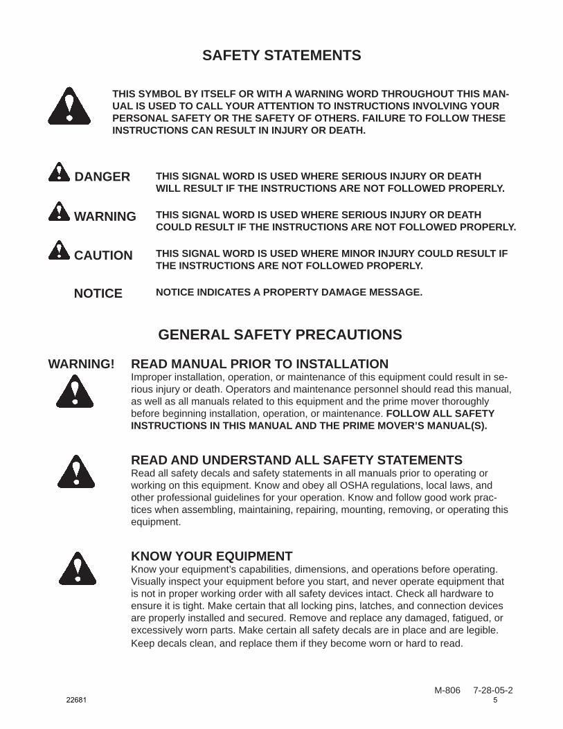
SAFETY STATEMENTS
DANGER
GENERAL SAFETY PRECAUTIONS
WARNING! READ MANUAL PRIOR TO INSTALLATIONImproper installation, operation, or maintenance of this equipment could result in se-rious injury or death. Operators and maintenance personnel should read this manual, as well as all manuals related to this equipment and the prime mover thoroughly before beginning installation, operation, or maintenance. FOLLOW ALL SAFETY INSTRUCTIONS IN THIS MANUAL AND THE PRIME MOVER’S MANUAL(S).
READ AND UNDERSTAND ALL SAFETY STATEMENTSRead all safety decals and safety statements in all manuals prior to operating or working on this equipment. Know and obey all OSHA regulations, local laws, and other professional guidelines for your operation. Know and follow good work prac-tices when assembling, maintaining, repairing, mounting, removing, or operating this equipment.
KNOW YOUR EQUIPMENTKnow your equipment’s capabilities, dimensions, and operations before operating. Visually inspect your equipment before you start, and never operate equipment that is not in proper working order with all safety devices intact. Check all hardware to ensure it is tight. Make certain that all locking pins, latches, and connection devices are properly installed and secured. Remove and replace any damaged, fatigued, or excessively worn parts. Make certain all safety decals are in place and are legible. Keep decals clean, and replace them if they become worn or hard to read.
WARNING
CAUTION
THIS SIGNAL WORD IS USED WHERE SERIOUS INJURY OR DEATHWILL RESULT IF THE INSTRUCTIONS ARE NOT FOLLOWED PROPERLY.
THIS SIGNAL WORD IS USED WHERE SERIOUS INJURY OR DEATHCOULD RESULT IF THE INSTRUCTIONS ARE NOT FOLLOWED PROPERLY.
THIS SIGNAL WORD IS USED WHERE MINOR INJURY COULD RESULT IF THE INSTRUCTIONS ARE NOT FOLLOWED PROPERLY.
NOTICE INDICATES A PROPERTY DAMAGE MESSAGE. NOTICE
THIS SYMBOL BY ITSELF OR WITH A WARNING WORD THROUGHOUT THIS MAN-UAL IS USED TO CALL YOUR ATTENTION TO INSTRUCTIONS INVOLVING YOUR PERSONAL SAFETY OR THE SAFETY OF OTHERS. FAILURE TO FOLLOW THESE INSTRUCTIONS CAN RESULT IN INJURY OR DEATH.
22681 5
GENERAL SAFETY PRECAUTIONS
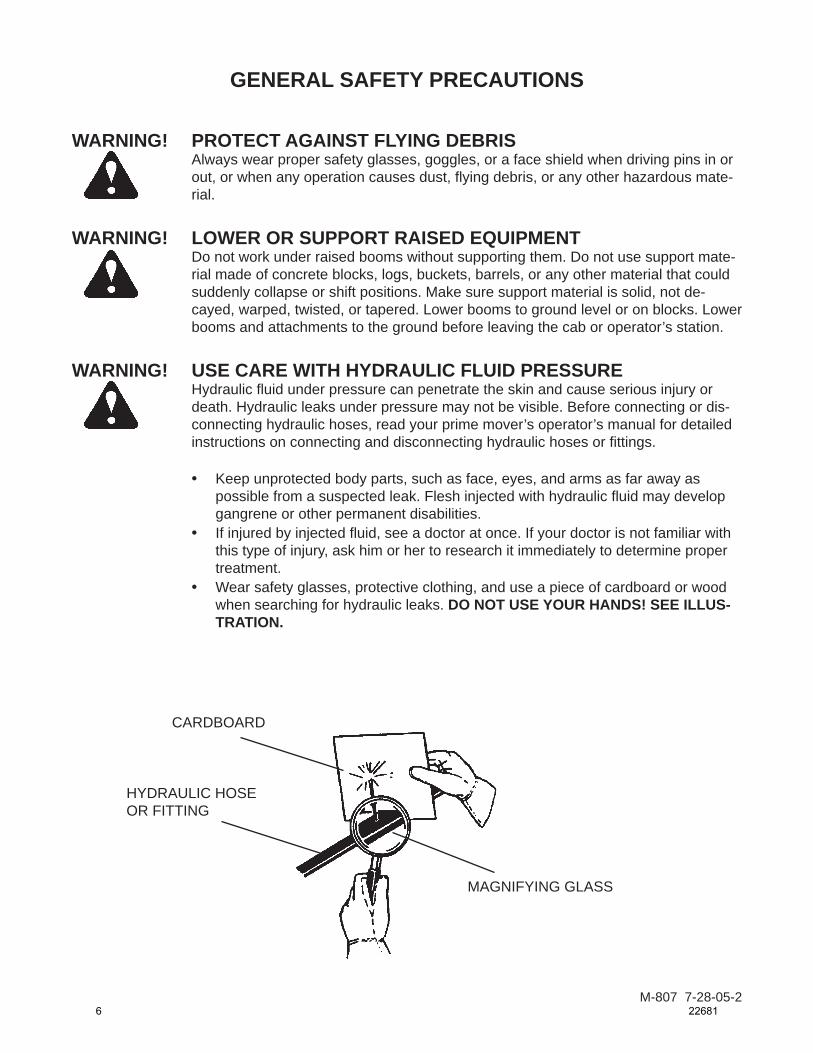
WARNING! PROTECT AGAINST FLYING DEBRISAlways wear proper safety glasses, goggles, or a face shield when driving pins in or out, or when any operation causes dust, fl ying debris, or any other hazardous mate-rial.
WARNING! LOWER OR SUPPORT RAISED EQUIPMENTDo not work under raised booms without supporting them. Do not use support mate-rial made of concrete blocks, logs, buckets, barrels, or any other material that could suddenly collapse or shift positions. Make sure support material is solid, not de-cayed, warped, twisted, or tapered. Lower booms to ground level or on blocks. Lower booms and attachments to the ground before leaving the cab or operator’s station.
WARNING! USE CARE WITH HYDRAULIC FLUID PRESSUREHydraulic fl uid under pressure can penetrate the skin and cause serious injury or death. Hydraulic leaks under pressure may not be visible. Before connecting or dis-connecting hydraulic hoses, read your prime mover’s operator’s manual for detailed instructions on connecting and disconnecting hydraulic hoses or fi ttings.
• Keep unprotected body parts, such as face, eyes, and arms as far away as possible from a suspected leak. Flesh injected with hydraulic fl uid may develop gangrene or other permanent disabilities.
• If injured by injected fl uid, see a doctor at once. If your doctor is not familiar with this type of injury, ask him or her to research it immediately to determine proper treatment.
• Wear safety glasses, protective clothing, and use a piece of cardboard or wood when searching for hydraulic leaks. DO NOT USE YOUR HANDS! SEE ILLUS-TRATION.
CARDBOARD
HYDRAULIC HOSEOR FITTING
MAGNIFYING GLASS
M-807 7-28-05-26 22681
GENERAL SAFETY PRECAUTIONS
M-808 7-28-05-2
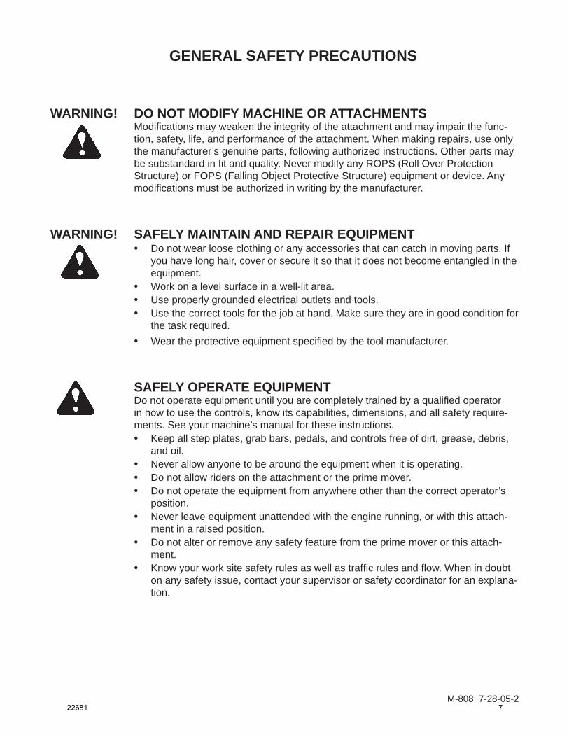
WARNING! DO NOT MODIFY MACHINE OR ATTACHMENTSModifi cations may weaken the integrity of the attachment and may impair the func-tion, safety, life, and performance of the attachment. When making repairs, use only the manufacturer’s genuine parts, following authorized instructions. Other parts may be substandard in fi t and quality. Never modify any ROPS (Roll Over Protection Structure) or FOPS (Falling Object Protective Structure) equipment or device. Any modifi cations must be authorized in writing by the manufacturer.
WARNING! SAFELY MAINTAIN AND REPAIR EQUIPMENT• Do not wear loose clothing or any accessories that can catch in moving parts. If
you have long hair, cover or secure it so that it does not become entangled in the equipment.
• Work on a level surface in a well-lit area.• Use properly grounded electrical outlets and tools.• Use the correct tools for the job at hand. Make sure they are in good condition for
the task required.• Wear the protective equipment specifi ed by the tool manufacturer.
SAFELY OPERATE EQUIPMENTDo not operate equipment until you are completely trained by a qualifi ed operator in how to use the controls, know its capabilities, dimensions, and all safety require-ments. See your machine’s manual for these instructions.• Keep all step plates, grab bars, pedals, and controls free of dirt, grease, debris,
and oil.• Never allow anyone to be around the equipment when it is operating.• Do not allow riders on the attachment or the prime mover.• Do not operate the equipment from anywhere other than the correct operator’s
position. • Never leave equipment unattended with the engine running, or with this attach-
ment in a raised position.• Do not alter or remove any safety feature from the prime mover or this attach-
ment.• Know your work site safety rules as well as traffi c rules and fl ow. When in doubt
on any safety issue, contact your supervisor or safety coordinator for an explana-tion.
22681 7

EQUIPMENT SAFETY PRECAUTIONSWARNING! KNOW WHERE UTILITIES ARE
Observeoverheadelectricalandotherutilitylines.Besureequipmentwillclearthem.Whendigging,callyourlocalutilitiesforlocationofburiedutilitylines,gas,water,andsewer,aswellasanyotherhazardyoumayencounter.
OPERATING THE PRIME MOVERAvoidsteephillsideoperation,whichcouldcausetheprimemovertooverturn.Consultyourprimemoveroperator’sandsafetymanualsformaximuminclineallowable.
EXPOSURE TO RESPIRABLE CRYSTALLINE SILICA DUST ALONG WITH OTHER HAZARDOUS DUSTS MAY CAUSE SERIOUS OR FATAL RESPIRATORY DISEASE.Itisrecommendedtousedustsuppression,dustcollectionandifnecessary,personalprotectiveequipmentduringtheoperationofanyattachmentthatmaycausehighlevelsofdust.
WORKING WITH THE AUGER•Allbystandersshouldbekeptaminimumof10feet(3meters)awayfromtheworking
areaoftheearthauger.•Anoperatormustnotusedrugsoralcohol,whichcanchangehisorheralertnessor
coordination.Anoperator takingprescriptionorover-the-counterdrugsshouldseekmedicaladviceonwhetherornotheorshecansafelyoperateequipment.
•Beforeexitingtheprimemover,lowertheearthaugertotheground,turnofftheprimemover’sengine,andlocktheprimemover’sbrakes.
•Flow and pressure gauges, fittings, and hoses must have a continuous operating pres-sureratingofatleast25%higherthanhighestpressuresofthesystem.
TRANSPORTING THE AUGER•Travelonlywiththeearthaugerinasafetransportpositiontopreventuncontrolled
movement.Driveslowlyoverroughgroundandonslopes.•Tethertheearthaugerwithachain,ifnecessary,topreventuncontrolledswingingof
theaugerwhenmovingfromholetohole.•Removetheearthaugerfromtheprimemoverbeforetransportingtoandfromthejob
site.
MAINTAINING THE AUGER•Neveradjustareliefvalveforpressurehigherthanrecommendedbytheprimemover
manufacturer.• Never perform any work on an earth auger unless you are authorized and qualified to
doso.Alwaysreadtheoperatorservicemanual(s)beforeanyrepair ismade.Aftercompletingmaintenanceorrepair,checkforcorrectfunctioningoftheearthauger.Ifnotfunctioningproperly,alwaystag“DONOTOPERATE”untilallproblemsarecor-rected.
•Worn,damaged,orillegiblesafetydecalsmustbereplaced.NewsafetydecalscanbeorderedfromMcMillen®.
M-8099-17-07-2
8 22681

INSTALLATION INSTRUCTIONS
M-1650 10-22-07
GENERAL INFORMATION Find the mounting kit diagram and parts list for the kit you have received. Study the diagram and familiarize yourself with the names of the various parts. This knowledge will assist you in understanding these instructions.
Read these instructions carefully before attempting to mount the auger.
READ AND UNDERSTAND ALL SAFETY INFORMATION PRIOR TO MOUNTING YOUR AUGER.
QUICK ATTACH MOUNTING ASSEMBLIES(Includes some Excavator Mounts, Telehandler Mounts and all Skid Steer & Wheel Loader Mounts.)
1. Remove the bucket or other attachment from the prime mover quick attach mechanism.
2. Attach the quick attach mounting bracket to the prime mover quick attach mechanism, as per manufacturer’s recommendations.
3. Attach the swivel (#21694) to the quick attach mounting bracket with pin (#22255) pro-vided. Secure the pin in place with klik pins (#21169).
4. If your mounting bracket is designed for the installation of a cradle, bolt the cradle to the bracket using the .50” UNC X 2.00” capscrews, lock washers and hex nuts provided.
5. Install the drive unit to the swivel using the pin provided with the drive unit assembly.
6. Install the auger to the drive unit with the bolt and nut provided with the drive unit as-sembly.
7. Refer to the “HYDRAULIC SYSTEM HOOK-UP” section in this manual for hydraulic connection instructions and recommendations.
BACKHOE AND EXCAVATOR “PENDULUM” MOUNTING ASSEMBLIES1. Remove the bucket from the dipper arm and curl cylinder pin connections. The dipper
arm pin will be used to attach auger pendulum mounting to the dipper arm. Curl cylinder pin will not be required for auger installation.
2. If using a universal adjustable width pendulum mounting assembly: Space the two back-hoe adapter ears to the same width as the dipper arm and secure to the base using the .50” hardware provided. After determining the correct width, the backhoe adapter ears must be welded to the base.
22681 9
INSTALLATION INSTRUCTIONS
M-1651 10-22-07
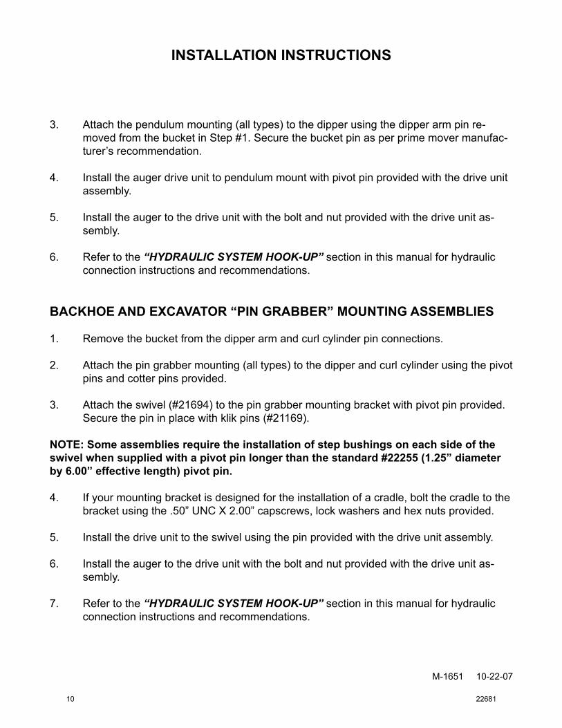
3. Attach the pendulum mounting (all types) to the dipper using the dipper arm pin re-moved from the bucket in Step #1. Secure the bucket pin as per prime mover manufac-turer’s recommendation.
4. Install the auger drive unit to pendulum mount with pivot pin provided with the drive unit assembly.
5. Install the auger to the drive unit with the bolt and nut provided with the drive unit as-sembly.
6. Refer to the “HYDRAULIC SYSTEM HOOK-UP” section in this manual for hydraulic connection instructions and recommendations.
BACKHOE AND EXCAVATOR “PIN GRABBER” MOUNTING ASSEMBLIES
1. Remove the bucket from the dipper arm and curl cylinder pin connections.
2. Attach the pin grabber mounting (all types) to the dipper and curl cylinder using the pivot pins and cotter pins provided.
3. Attach the swivel (#21694) to the pin grabber mounting bracket with pivot pin provided. Secure the pin in place with klik pins (#21169).
NOTE: Some assemblies require the installation of step bushings on each side of the swivel when supplied with a pivot pin longer than the standard #22255 (1.25” diameter by 6.00” effective length) pivot pin.
4. If your mounting bracket is designed for the installation of a cradle, bolt the cradle to the bracket using the .50” UNC X 2.00” capscrews, lock washers and hex nuts provided.
5. Install the drive unit to the swivel using the pin provided with the drive unit assembly.
6. Install the auger to the drive unit with the bolt and nut provided with the drive unit as-sembly.
7. Refer to the “HYDRAULIC SYSTEM HOOK-UP” section in this manual for hydraulic connection instructions and recommendations.
10 22681

UNIVERSAL FRONT END LOADER MOUNTING ASSEMBLY1 The universal front end loader mounting assembly (#21235) can be used to adapt your
McMillen Earth Auger to the side of the loader arm, lip of a bucket, or fork lift forks. DO NOT USE ON SKID -STEER LOADERS.
2. Place loader bracket clamp plate (#21449) on the inside of the loader arm, top of the bucket lip or top of fork lift fork.
NOTE: For mounting on lip of bucket you will need to drill two 7/16” diameter holes through the bucket.
3. Place the loader bracket #21628 on the opposite side of clamp plate and secure with the four .44” bolts #1080 and hex nuts #1227 provided.
4. Attach the swivel (#21694) to the loader mounting bracket with pivot pin #22255 pro-vided. Secure the pin in place with klik pins (#21169).
5. Install the drive unit to the swivel using the pin provided with the drive unit assembly.
6. Install the auger to the drive unit with the bolt and nut provided with the drive unit as-sembly.
7. Refer to the “HYDRAULIC SYSTEM HOOK-UP” section in this manual for hydraulic connection instructions and recommendations.
WELD-ON EXCAVATOR MOUNTING McMillen offers a blank weld on plate with mounting ears and swivel for welding onto your own excavator mounting bracket.
After securely welding the plate onto your bracket:
1. Attach the swivel (#21694) to the mounting plate with pivot pin #22255 provided. Secure the pin in place with klik pins #21169.
2. Install the drive unit to the swivel using the pin provided with the drive unit assembly.
3. Install the auger to the drive unit with the bolt and nut provided with the drive unit as-sembly.
4. Refer to the “HYDRAULIC SYSTEM HOOK-UP” section in this manual for hydraulic connection instructions and recommendations.
INSTALLATION INSTRUCTIONS
M-1652 10-22-07
22681 11

M-129 5-7-08-2
GENERAL INFORMATION Once the installation instructions are complete, you are now ready to make the hydrau-lic connections necessary to operate your earth drill.
READ AND UNDERSTAND SAFETY INFORMATION PRIOR TO MAKING HYDRAULIC CONNECTIONS.
Your equipment dealer is in the best position to advise you as to where the best place on your machine is to make the hydraulic connections to power your earth drill drive unit. The list below shows the most common places to “tap” into the hydraulic system on various types of machines.
• SKID STEER LOADERS - Auxiliary hydraulic outlets.
• BACKHOES & EXCAVATORS - Auxiliary hydraulic outlets or bucket curl cylinder circuit.
• WHEEL LOADERS & TRACTOR LOADERS - Auxiliary hydraulic outlets or bucket tilt (dump) cylinder circuit.
Determine the length of hydraulic hoses required to plumb drive unit into the place on your machine where you will be “tapping” into the hydraulics. Be sure the two hydraulic hoses are long enough to perform at the full range of the earth drill’s operating capacity. A case drain line may also be required to operate your earth drill.
• Models 975, 1475, 1975, 2475 and 3575 require two 1/2”(12.7mm) or 3/4” (19mm) ID hydraulic hoses with #10 JIC Female fittings on one end of each hose to connect hoses to drive unit fittings.
• Models 3450 and 4450 ONLY. These models are designed for maximum back pressure of 400 psi (28 kg/cm2) and require two 3/4” (19mm) hydraulic hoses with #12 JIC Female fit-tings on one end of each hose to connect hoses to drive unit fittings.
For back pressures exceeding 400 psi (28 kg/cm2): A Drain Line Kit (Part #21218) is available for models 3450 and 4450 when back pressures exceed 400 psi. To order, contact your local dealer.
NOTE: Fittings on the other end of each hydraulic hose should match the threads on the hy-draulic quick couplers to be used.
WARNING! HOSES AND FITTINGS MUST HAVE A CONTINUOUS OPERATING PRES-SURE RATING OF AT LEAST 25% HIGHER THAN THE HIGHEST PRES-SURES OF THE SYSTEM YOU ARE “TAPPING” INTO.
Once all of the hydraulic connections have been made and checked for leaks, you are now ready to operate your earth drill. READ AND UNDERSTAND OPERATING INSTRUC-TIONS AND SAFETY INFORMATION PRIOR TO OPERATING YOUR EARTH DRILL.
HYDRAULIC SYSTEM HOOK-UP INSTRUCTIONS
12 22681
OPERATING INSTRUCTIONS
M-1656 11-12-07
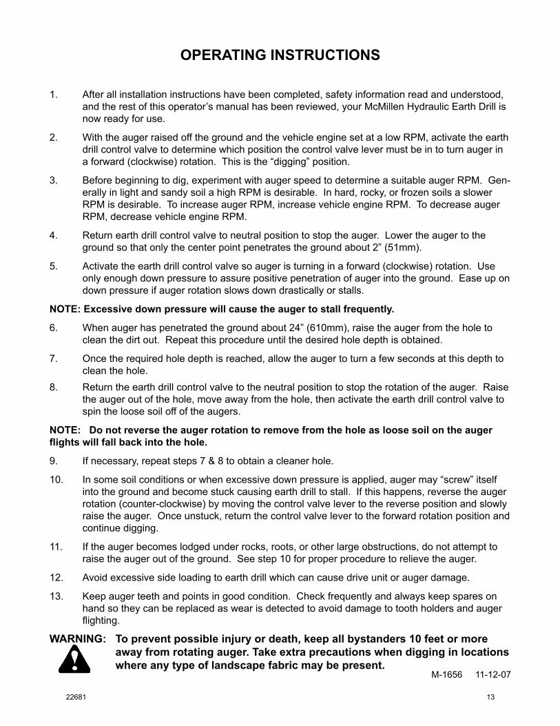
1. After all installation instructions have been completed, safety information read and understood, and the rest of this operator’s manual has been reviewed, your McMillen Hydraulic Earth Drill is now ready for use.
2. With the auger raised off the ground and the vehicle engine set at a low RPM, activate the earth drill control valve to determine which position the control valve lever must be in to turn auger in a forward (clockwise) rotation. This is the “digging” position.
3. Before beginning to dig, experiment with auger speed to determine a suitable auger RPM. Gen-erally in light and sandy soil a high RPM is desirable. In hard, rocky, or frozen soils a slower RPM is desirable. To increase auger RPM, increase vehicle engine RPM. To decrease auger RPM, decrease vehicle engine RPM.
4. Return earth drill control valve to neutral position to stop the auger. Lower the auger to the ground so that only the center point penetrates the ground about 2” (51mm).
5. Activate the earth drill control valve so auger is turning in a forward (clockwise) rotation. Use only enough down pressure to assure positive penetration of auger into the ground. Ease up on down pressure if auger rotation slows down drastically or stalls.
NOTE: Excessive down pressure will cause the auger to stall frequently.
6. When auger has penetrated the ground about 24” (610mm), raise the auger from the hole to clean the dirt out. Repeat this procedure until the desired hole depth is obtained.
7. Once the required hole depth is reached, allow the auger to turn a few seconds at this depth to clean the hole.
8. Return the earth drill control valve to the neutral position to stop the rotation of the auger. Raise the auger out of the hole, move away from the hole, then activate the earth drill control valve to spin the loose soil off of the augers.
NOTE: Do not reverse the auger rotation to remove from the hole as loose soil on the auger flights will fall back into the hole.
9. If necessary, repeat steps 7 & 8 to obtain a cleaner hole.
10. In some soil conditions or when excessive down pressure is applied, auger may “screw” itself into the ground and become stuck causing earth drill to stall. If this happens, reverse the auger rotation (counter-clockwise) by moving the control valve lever to the reverse position and slowly raise the auger. Once unstuck, return the control valve lever to the forward rotation position and continue digging.
11. If the auger becomes lodged under rocks, roots, or other large obstructions, do not attempt to raise the auger out of the ground. See step 10 for proper procedure to relieve the auger.
12. Avoid excessive side loading to earth drill which can cause drive unit or auger damage.
13. Keep auger teeth and points in good condition. Check frequently and always keep spares on hand so they can be replaced as wear is detected to avoid damage to tooth holders and auger flighting.
WARNING: To prevent possible injury or death, keep all bystanders 10 feet or more away from rotating auger. Take extra precautions when digging in locations where any type of landscape fabric may be present.
22681 13
MAINTENANCE
M-1727 2-18-08
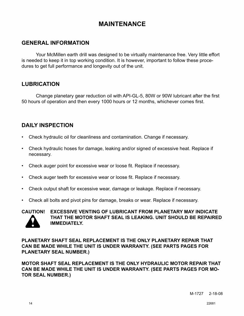
GENERAL INFORMATION
Your McMillen earth drill was designed to be virtually maintenance free. Very little effort is needed to keep it in top working condition. It is however, important to follow these proce-dures to get full performance and longevity out of the unit.
LUBRICATION
ChangeplanetarygearreductionoilwithAPI-GL-5,80Wor90Wlubricantafterthefirst50hoursofoperationandthenevery1000hoursor12months,whichevercomesfirst.
DAILY INSPECTION
Check hydraulic oil for cleanliness and contamination. Change if necessary.
Check hydraulic hoses for damage, leaking and/or signed of excessive heat. Replace if necessary.
Checkaugerpointforexcessivewearorloosefit.Replaceifnecessary.
Checkaugerteethforexcessivewearorloosefit.Replaceifnecessary.
Check output shaft for excessive wear, damage or leakage. Replace if necessary.
Check all bolts and pivot pins for damage, breaks or wear. Replace if necessary.
CAUTION! EXCESSIVE VENTING OF LUBRICANT FROM PLANETARY MAY INDICATE THAT THE MOTOR SHAFT SEAL IS LEAKING. UNIT SHOULD BE REPAIRED IMMEDIATELY.
PLANETARY SHAFT SEAL REPLACEMENT IS THE ONLY PLANETARY REPAIR THAT CAN BE MADE WHILE THE UNIT IS UNDER WARRANTY. (SEE PARTS PAGES FOR PLANETARY SEAL NUMBER.)
MOTOR SHAFT SEAL REPLACEMENT IS THE ONLY HYDRAULIC MOTOR REPAIR THAT CAN BE MADE WHILE THE UNIT IS UNDER WARRANTY. (SEE PARTS PAGES FOR MO-TOR SEAL NUMBER.)
•
•
•
•
•
•
14 22681

MAINTENANCE
M-1728 2-18-08
PLANETARY GEARBOX ChangegearboxoilusingAPI-GL-5,80Wor90Wlubricantafterthefirst50hoursofoperationandthenevery1200hoursor12months,whichevercomesfirst.Checkoillevelfre-quently to maintain proper lubrication.
CHECKING PLANETARY LUBRICANT1. Place the planetary in a horizontal position. 2. Removefillplug.3. Checkthelubricantlevel.Gearlublevelshouldbevisiblethroughthefillplughole.4. ToFill:Tilttheplanetaryslightly(maximum15°)andaddlubricantuptofillpluglocation.
With the planetary in this position , lubricant should cover the internal gear and be vis-iblethroughthefillholewheninahorizontalposition.
FILL PLUG REMOVED
PLANETARY
DRAIN PLUG
PLANETARY - TILTED 15°
FILL PLUG REMOVED
DRAIN PLUG
STORAGE PROCEDURE1. Check to ensure that hydraulic motor and hoses are full of clean oil.2. Be sure planetary is full of clean lubricant.3. Clean unit thoroughly, removing all mud, dirt, and grease.4. Tighten all loose hardware.5. Touch up unpainted and exposed areas with paint to prevent rust.6. Coat the drive unit output shaft, inside of auger collar, variable auger extension shaft
and inside of auger extension collar to prevent rust and reduce wear.7. Store the unit in a dry and protected place. Leaving the auger and drive unit outside,
exposed to the elements, will materially shorten its life.8. Inspect the unit for visible signs of wear, breakage or damage. Order any parts required
and make necessary repairs to avoid delays when starting next season.9. Replace decals if damaged or in unreadable condition.
22681 15
MAINTENANCE
M-1919 2-18-07
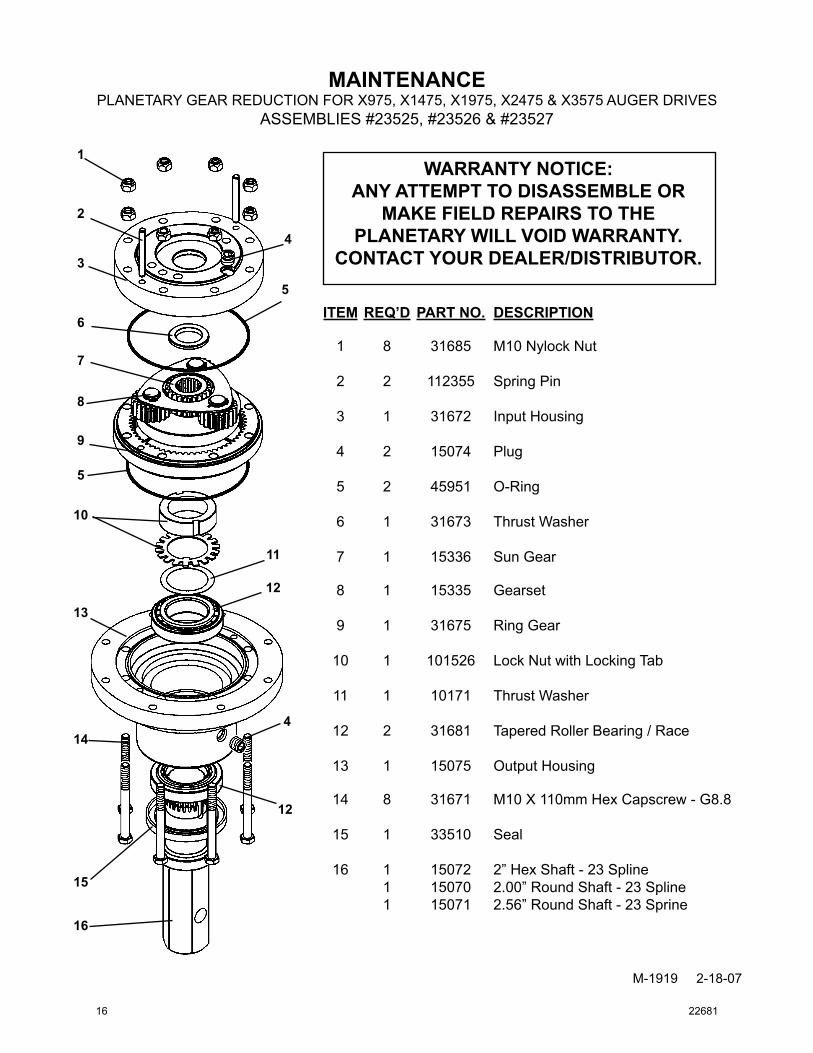
PLANETARY GEAR REDUCTION FOR X975, X1475, X1975, X2475 & X3575 AUGER DRIVESASSEMBLIES #23525, #23526 & #23527
ITEMREQ’D PARTNO. DESCRIPTION
1 8 31685 M10 Nylock Nut
2 2 112355 Spring Pin
3 1 31672 Input Housing
4 2 15074 Plug
5 2 45951 O-Ring
6 1 31673 Thrust Washer
7 1 15336 Sun Gear
8 1 15335 Gearset
9 1 31675 Ring Gear
10 1 101526 Lock Nut with Locking Tab
11 1 10171 Thrust Washer
12 2 31681 Tapered Roller Bearing / Race
13 1 15075 Output Housing
14 8 31671 M10 X 110mm Hex Capscrew - G8.8
15 1 33510 Seal
16 1 15072 2” Hex Shaft - 23 Spline 1 15070 2.00” Round Shaft - 23 Spline 1 15071 2.56” Round Shaft - 23 Sprine
1
2
3
4
5
6
7
8
5
9
10
11
12
13
14
15
16
wARRANTyNOTICE:ANyATTEMPTTODISASSEMBLEOR
MAKEFIELDREPAIRSTOTHEPLANETARywILLVOIDwARRANTy.
CONTACTyOURDEALER/DISTRIBUTOR.
12
4
16 22681
Gag
e To
oth
Wis
dom
Too
th
Chi
sel T
ooth
C
arbi
de W
isdo
m T
ooth
IMPO
RTA
NT:
M
cMill
end
oes
notr
ecom
men
dau
gers
exc
eedi
ng3
6”d
iam
eter
for
C-S
erie
sD
rive
Uni
ts.
M-1
18 4
-27-
05-3
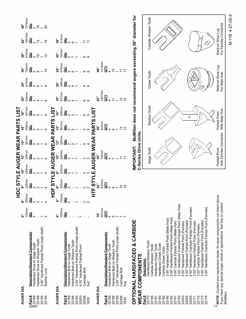
HD
CS
TYLE
AU
GER
WEA
RP
AR
TSL
IST
AU
GER
DIA
.
6”
8”
9”
10”
12”
15”
16”
18”
20”
24”
30”
36”
42”
48”
15
2mm
20
3mm
22
9mm
25
4mm
30
5mm
38
1mm
40
6mm
45
7mm
50
8mm
61
0mm
76
2mm
91
4mm
10
67m
m
1219
mm
Part
#
Des
crip
tion(
Stan
dard
Com
pone
nts)
Q
ty
Qty
Q
ty
Qty
Q
ty
Qty
Q
ty
Qty
Q
ty
Qty
Q
ty
Qty
Q
ty
Qty
2216
9 H
arde
ned
Driv
e-In
Gag
e To
oth
2 2
2 2
2 2
2 2
2 2
2 2
2 2
2216
8 H
arde
ned
Driv
e-In
Wis
dom
Too
th
- 2
2 2
2 4
4 4
4 6
8 10
14
18
2219
0 3.
50” H
arde
ned
Fish
tail
Poi
nt (m
ale
shaf
t) 1
1 1
1 1
1 1
1 1
1 1
1 1
122
154
Rub
ber L
ock
2 4
4 4
4 6
6 6
6 8
10
12
16
20
HD
FST
YLE
AU
GER
WEA
RP
AR
TSL
IST
AU
GER
DIA
.
4”
6”
8”
9”
10”
12”
15”
16”
18”
20”
24”
30”
36”
10
2mm
15
2mm
20
3mm
22
9mm
25
4mm
30
5mm
38
1mm
40
6mm
45
7mm
50
8mm
61
0mm
76
2mm
91
4mm
Part
#
Des
crip
tion(
Stan
dard
Com
pone
nts)
Q
ty
Qty
Q
ty
Qty
Q
ty
Qty
Q
ty
Qty
Q
ty
Qty
Q
ty
Qty
Q
ty22
169
Har
dene
d B
olt-o
n G
age
Toot
h -
2 2
2 2
2 2
2 2
2 2
2 2
2216
8 H
arde
ned
Bol
t-on
Wis
dom
Too
th
- -
- 1
1 2
3 3
4 4
6 7
922
190
3.50
” Har
dene
d Fi
shta
il P
oint
(mal
e sh
aft)
- 1
1 1
1 1
1 1
1 1
1 1
122
003
4.50
” Har
dene
d Fi
shta
il P
oint
1
- -
- -
- -
- -
- -
- -
2230
6 C
arria
ge B
olt
- 2
2 3
3 4
5 5
6 6
8 9
1118
39
Nut
- 2
2 3
3 4
5 5
6 6
8 9
11
HTF
STY
LEA
UG
ERW
EAR
PA
RTS
LIS
TA
UG
ERD
IA.
18
”
24”
30
”
36”
42
”
48”
45
7mm
610m
m
76
2mm
914m
m
10
67m
m
12
19m
mPa
rt#
D
escr
iptio
n(St
anda
rdC
ompo
nent
s)
QTY
QTY
QTY
QTY
QTY
QTY
2216
9 H
arde
ned
Bol
t-on
Gag
e To
oth
4
4
4
4
4
422
168
Har
dene
d B
olt-o
n W
isdo
m T
ooth
3
6
7
9
11
13
2219
0 3.
50” H
arde
ned
Fish
tail
Poi
nt (m
ale
shaf
t) 1
1
1
1
1
1
2230
6 C
arria
ge B
olt
7
10
11
13
15
1718
39
Nut
7
10
11
13
15
17
OPT
ION
AL
HA
RD
FAC
ED&
CA
Rb
IDE
WEA
RC
OM
PON
ENTS
Part
#
D
escr
iptio
n
2217
0
Har
dfac
ed W
isdo
m T
ooth
2218
6
Car
bide
Wis
dom
Too
th
22
181
H
arde
ned
Chi
sel T
ooth
2218
3
Har
dfac
ed C
hise
l Too
th
22
182
C
arbi
de C
hise
l Too
th
22
190
3.
50” H
arde
ned
Fish
tail
Poi
nt (M
ale
Hub
)22
192
3.
50” H
ardf
aced
Fis
htai
l Poi
nt (M
ale
Hub
)22
191
3.
50” C
arbi
de F
isht
ail P
oint
(Mal
e H
ub)
2219
3
3.50
” Har
dfac
ed /C
arbi
de F
isht
ail P
oint
(Mal
e H
ub)
2200
3
4.50
” Har
dene
d Fi
shta
il P
oint
(Fem
ale)
2200
4
4.50
” Har
dfac
ed F
isht
ail P
oint
(Fem
ale)
2200
5
4.50
” Har
dfac
ed /C
arbi
de F
isht
ail P
oint
(Fem
ale)
2217
1
3.50
” Har
dene
d Fi
shta
il P
oint
(Fem
ale)
2217
2
3.50
” Car
bide
Fis
htai
l Poi
nt (F
emal
e)22
173
3.
50” H
ardf
aced
Fis
htai
l Poi
nt (F
emal
e)22
174
3.
50” H
ardf
aced
/Car
bide
Fis
htai
l Poi
nt (F
emal
e)
NO
TE: C
onta
ct y
our e
quip
men
t dea
ler f
or w
ear c
ompo
nent
s no
t lis
ted
abov
e.
If yo
u ha
ve a
ny s
peci
al a
uger
nee
ds o
r app
licat
ions
, fee
l fre
e to
con
tact
M
cMill
en.
Fish
tail
Poi
nt
F
isht
ail P
oint
W
eld-
on D
rive
Lug
W
eld-
on D
rive
Lug
With
Fem
ale
Con
nect
or
With
Mal
e H
ub
F
or M
ale
Hub
For
Fem
ale
Con
nect
or
22681 17
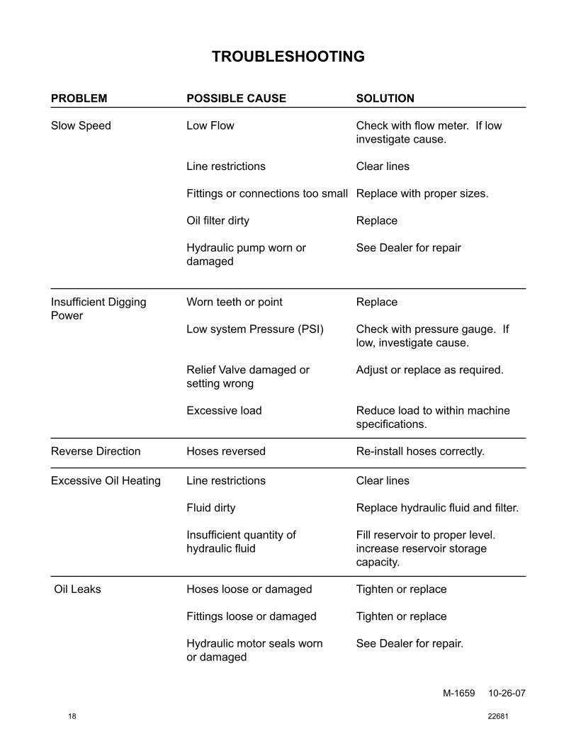
TROUBLESHOOTING
M-1659 10-26-07
PROBLEM POSSIBLECAUSE SOLUTION
Slow Speed Low Flow Check with flow meter. If low investigate cause.
Line restrictions Clear lines
Fittings or connections too small Replace with proper sizes.
Oil filter dirty Replace
Hydraulic pump worn or See Dealer for repair damaged
Insufficient Digging Worn teeth or point ReplacePower Low system Pressure (PSI) Check with pressure gauge. If low, investigate cause.
Relief Valve damaged or Adjust or replace as required. setting wrong
Excessive load Reduce load to within machine specifications.
Reverse Direction Hoses reversed Re-install hoses correctly.
Excessive Oil Heating Line restrictions Clear lines
Fluid dirty Replace hydraulic fluid and filter.
Insufficient quantity of Fill reservoir to proper level. hydraulic fluid increase reservoir storage capacity.
Oil Leaks Hoses loose or damaged Tighten or replace
Fittings loose or damaged Tighten or replace
Hydraulic motor seals worn See Dealer for repair. or damaged
18 22681
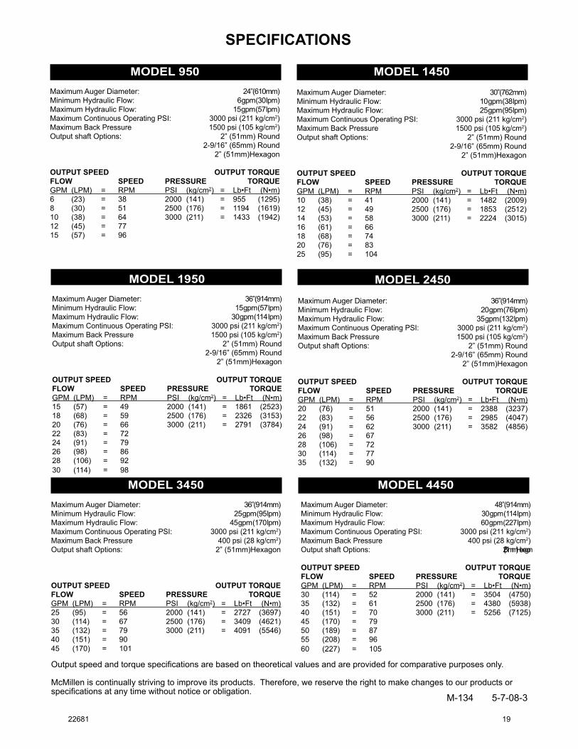
M-134 5-7-08-3
MODEL 950Maximum Auger Diameter: 24” (610mm)Minimum Hydraulic Flow: 6 gpm (30 lpm)Maximum Hydraulic Flow: 15 gpm (57 lpm)Maximum Continuous Operating PSI: 3000 psi (211 kg/cm2)Maximum Back Pressure 1500 psi (105 kg/cm2) Output shaft Options: 2” (51mm) Round 2-9/16” (65mm) Round 2” (51mm)Hexagon
OUTPUT SPEED OUTPUT TORQUEFLOW SPEED PRESSURE TORQUEGPM (LPM) = RPM PSI (kg/cm2) = Lb•Ft (N•m)6 (23) = 38 2000 (141) = 955 (1295)8 (30) = 51 2500 (176) = 1194 (1619)10 (38) = 64 3000 (211) = 1433 (1942)12 (45) = 77 15 (57) = 96
SPECIFICATIONS
Output speed and torque specifications are based on theoretical values and are provided for comparative purposes only.
McMillen is continually striving to improve its products. Therefore, we reserve the right to make changes to our products or specifications at any time without notice or obligation.
MODEL 1450Maximum Auger Diameter: 30” (762mm)Minimum Hydraulic Flow: 10 gpm (38 lpm)Maximum Hydraulic Flow: 25 gpm (95 lpm)Maximum Continuous Operating PSI: 3000 psi (211 kg/cm2) Maximum Back Pressure 1500 psi (105 kg/cm2)Output shaft Options: 2” (51mm) Round 2-9/16” (65mm) Round 2” (51mm)Hexagon
OUTPUT SPEED OUTPUT TORQUEFLOW SPEED PRESSURE TORQUEGPM (LPM) = RPM PSI (kg/cm2) = Lb•Ft (N•m)10 (38) = 41 2000 (141) = 1482 (2009)12 (45) = 49 2500 (176) = 1853 (2512)14 (53) = 58 3000 (211) = 2224 (3015)16 (61) = 66 18 (68) = 74 20 (76) = 83 25 (95) = 104
MODEL 1950Maximum Auger Diameter: 36” (914mm)Minimum Hydraulic Flow: 15 gpm (57 lpm)Maximum Hydraulic Flow: 30 gpm (114 lpm)Maximum Continuous Operating PSI: 3000 psi (211 kg/cm2) Maximum Back Pressure 1500 psi (105 kg/cm2)Output shaft Options: 2” (51mm) Round 2-9/16” (65mm) Round 2” (51mm)Hexagon
OUTPUT SPEED OUTPUT TORQUEFLOW SPEED PRESSURE TORQUEGPM (LPM) = RPM PSI (kg/cm2) = Lb•Ft (N•m)15 (57) = 49 2000 (141) = 1861 (2523)18 (68) = 59 2500 (176) = 2326 (3153)20 (76) = 66 3000 (211) = 2791 (3784)22 (83) = 72 24 (91) = 79 26 (98) = 86 28 (106) = 92 30 (114) = 98
MODEL 2450
Maximum Auger Diameter: 36” (914mm)Minimum Hydraulic Flow: 20 gpm (76 lpm)Maximum Hydraulic Flow: 35 gpm (132 lpm)Maximum Continuous Operating PSI: 3000 psi (211 kg/cm2) Maximum Back Pressure 1500 psi (105 kg/cm2)Output shaft Options: 2” (51mm) Round 2-9/16” (65mm) Round 2” (51mm)Hexagon
OUTPUT SPEED OUTPUT TORQUEFLOW SPEED PRESSURE TORQUEGPM (LPM) = RPM PSI (kg/cm2) = Lb•Ft (N•m)20 (76) = 51 2000 (141) = 2388 (3237)22 (83) = 56 2500 (176) = 2985 (4047)24 (91) = 62 3000 (211) = 3582 (4856)26 (98) = 67 28 (106) = 72 30 (114) = 77 35 (132) = 90
MODEL 3450Maximum Auger Diameter: 36” (914mm)Minimum Hydraulic Flow: 25 gpm (95 lpm)Maximum Hydraulic Flow: 45 gpm (170 lpm)Maximum Continuous Operating PSI: 3000 psi (211 kg/cm2) Maximum Back Pressure 400 psi (28 kg/cm2)Output shaft Options: 2” (51mm)Hexagon
OUTPUT SPEED OUTPUT TORQUEFLOW SPEED PRESSURE TORQUEGPM (LPM) = RPM PSI (kg/cm2) = Lb•Ft (N•m)25 (95) = 56 2000 (141) = 2727 (3697)30 (114) = 67 2500 (176) = 3409 (4621)35 (132) = 79 3000 (211) = 4091 (5546)40 (151) = 90 45 (170) = 101
MODEL 4450Maximum Auger Diameter: 48” (914mm)Minimum Hydraulic Flow: 30 gpm (114 lpm)Maximum Hydraulic Flow: 60 gpm (227 lpm)Maximum Continuous Operating PSI: 3000 psi (211 kg/cm2) Maximum Back Pressure 400 psi (28 kg/cm2)Output shaft Options: 2” (51mm)Hexagon
OUTPUT SPEED OUTPUT TORQUEFLOW SPEED PRESSURE TORQUEGPM (LPM) = RPM PSI (kg/cm2) = Lb•Ft (N•m)30 (114) = 52 2000 (141) = 3504 (4750)35 (132) = 61 2500 (176) = 4380 (5938)40 (151) = 70 3000 (211) = 5256 (7125)45 (170) = 79 50 (189) = 87 55 (208) = 96 60 (227) = 105
22681 19
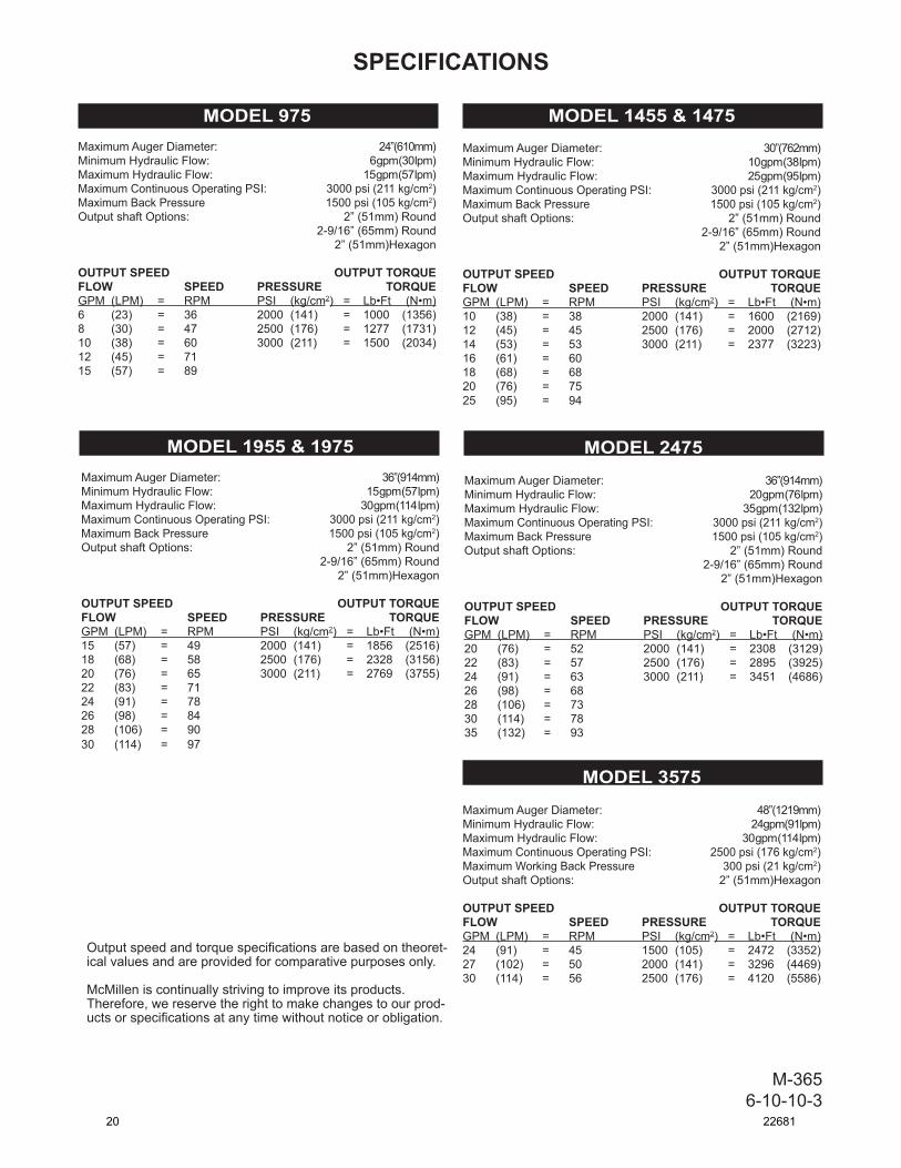
M-3656-10-10-3
MODEL 975Maximum Auger Diameter: 24” (610mm)Minimum Hydraulic Flow: 6 gpm (30 lpm)Maximum Hydraulic Flow: 15 gpm (57 lpm)Maximum Continuous Operating PSI: 3000 psi (211 kg/cm2)Maximum Back Pressure 1500 psi (105 kg/cm2) Output shaft Options: 2” (51mm) Round 2-9/16” (65mm) Round 2” (51mm)Hexagon
OUTPUT SPEED OUTPUT TORQUEFLOW SPEED PRESSURE TORQUEGPM (LPM) = RPM PSI (kg/cm2) = Lb•Ft (N•m)6 (23) = 36 2000 (141) = 1000 (1356)8 (30) = 47 2500 (176) = 1277 (1731)10 (38) = 60 3000 (211) = 1500 (2034)12 (45) = 71 15 (57) = 89
Output speed and torque specifications are based on theoret-ical values and are provided for comparative purposes only.
McMillen is continually striving to improve its products. Therefore, we reserve the right to make changes to our prod-ucts or specifications at any time without notice or obligation.
MODEL 1455 & 1475Maximum Auger Diameter: 30” (762mm)Minimum Hydraulic Flow: 10 gpm (38 lpm)Maximum Hydraulic Flow: 25 gpm (95 lpm)Maximum Continuous Operating PSI: 3000 psi (211 kg/cm2) Maximum Back Pressure 1500 psi (105 kg/cm2)Output shaft Options: 2” (51mm) Round 2-9/16” (65mm) Round 2” (51mm)Hexagon
OUTPUT SPEED OUTPUT TORQUEFLOW SPEED PRESSURE TORQUEGPM (LPM) = RPM PSI (kg/cm2) = Lb•Ft (N•m)10 (38) = 38 2000 (141) = 1600 (2169)12 (45) = 45 2500 (176) = 2000 (2712)14 (53) = 53 3000 (211) = 2377 (3223)16 (61) = 60 18 (68) = 68 20 (76) = 75 25 (95) = 94
MODEL 1955 & 1975Maximum Auger Diameter: 36” (914mm)Minimum Hydraulic Flow: 15 gpm (57 lpm)Maximum Hydraulic Flow: 30 gpm (114 lpm)Maximum Continuous Operating PSI: 3000 psi (211 kg/cm2) Maximum Back Pressure 1500 psi (105 kg/cm2)Output shaft Options: 2” (51mm) Round 2-9/16” (65mm) Round 2” (51mm)Hexagon
OUTPUT SPEED OUTPUT TORQUEFLOW SPEED PRESSURE TORQUEGPM (LPM) = RPM PSI (kg/cm2) = Lb•Ft (N•m)15 (57) = 49 2000 (141) = 1856 (2516)18 (68) = 58 2500 (176) = 2328 (3156)20 (76) = 65 3000 (211) = 2769 (3755)22 (83) = 71 24 (91) = 78 26 (98) = 84 28 (106) = 90 30 (114) = 97
MODEL 2475
Maximum Auger Diameter: 36” (914mm)Minimum Hydraulic Flow: 20 gpm (76 lpm)Maximum Hydraulic Flow: 35 gpm (132 lpm)Maximum Continuous Operating PSI: 3000 psi (211 kg/cm2) Maximum Back Pressure 1500 psi (105 kg/cm2)Output shaft Options: 2” (51mm) Round 2-9/16” (65mm) Round 2” (51mm)Hexagon
OUTPUT SPEED OUTPUT TORQUEFLOW SPEED PRESSURE TORQUEGPM (LPM) = RPM PSI (kg/cm2) = Lb•Ft (N•m)20 (76) = 52 2000 (141) = 2308 (3129)22 (83) = 57 2500 (176) = 2895 (3925)24 (91) = 63 3000 (211) = 3451 (4686)26 (98) = 68 28 (106) = 73 30 (114) = 78 35 (132) = 93
SPECIFICATIONS
MODEL 3575
Maximum Auger Diameter: 48” (1219mm)Minimum Hydraulic Flow: 24gpm (91 lpm)Maximum Hydraulic Flow: 30 gpm (114 lpm)Maximum Continuous Operating PSI: 2500 psi (176 kg/cm2) Maximum Working Back Pressure 300 psi (21 kg/cm2)Output shaft Options: 2” (51mm)Hexagon
OUTPUT SPEED OUTPUT TORQUEFLOW SPEED PRESSURE TORQUEGPM (LPM) = RPM PSI (kg/cm2) = Lb•Ft (N•m)24 (91) = 45 1500 (105) = 2472 (3352)27 (102) = 50 2000 (141) = 3296 (4469)30 (114) = 56 2500 (176) = 4120 (5586)
20 22681
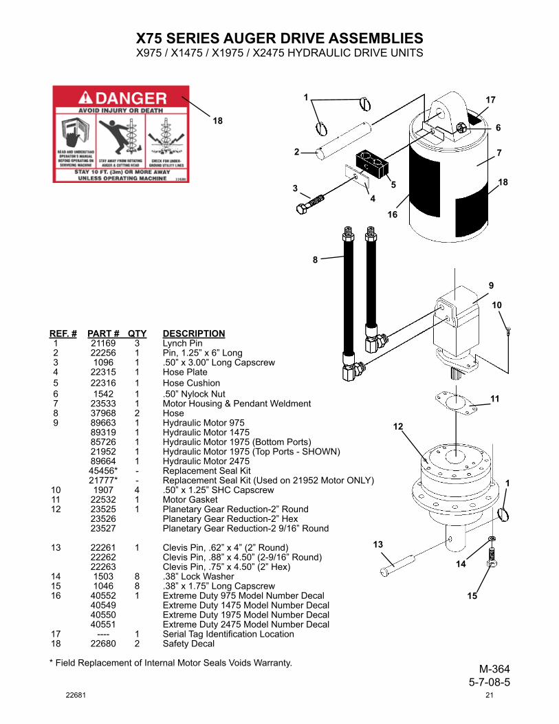
REF.# PART# QTY DESCRIPTION 1 21169 3 LynchPin 2 22256 1 Pin,1.25”x6”Long 3 1096 1 .50”x3.00”LongCapscrew 4 22315 1 HosePlate 5 22316 1 HoseCushion 6 1542 1 .50”NylockNut 7 23533 1 MotorHousing&PendantWeldment 8 37968 2 Hose 9 89663 1 HydraulicMotor975 89319 1 HydraulicMotor1475 85726 1 HydraulicMotor1975(BottomPorts) 21952 1 HydraulicMotor1975(TopPorts-SHOWN) 89664 1 HydraulicMotor2475 45456* - ReplacementSealKit 21777* - ReplacementSealKit(Usedon21952MotorONLY)10 1907 4 .50”x1.25”SHCCapscrew 11 22532 1 MotorGasket 12 23525 1 PlanetaryGearReduction-2”Round 23526 PlanetaryGearReduction-2”Hex 23527 PlanetaryGearReduction-29/16”Round
13 22261 1 ClevisPin,.62”x4”(2”Round) 22262 ClevisPin,.88”x4.50”(2-9/16”Round) 22263 ClevisPin,.75”x4.50”(2”Hex)14 1503 8 .38”LockWasher 15 1046 8 .38”x1.75”LongCapscrew 16 40552 1 ExtremeDuty975ModelNumberDecal 40549 ExtremeDuty1475ModelNumberDecal 40550 ExtremeDuty1975ModelNumberDecal 40551 ExtremeDuty2475ModelNumberDecal 17 ---- 1 SerialTagIdentificationLocation 18 22680 2 SafetyDecal
*FieldReplacementofInternalMotorSealsVoidsWarranty. M-3645-7-08-5
1
2
34
5
6
7
8
9
10
11
12
13
14
15
1
18
17
16
X75SERIESAUGERDRIVEASSEMBLIESX975/X1475/X1975/X2475HYDRAULICDRIVEUNITS
18
22681 21

X3575 AUGER DRIVE ASSEMBLY
M-1597 5-6-08
ASSEMBLY #24990
1
2
3
4
5
6
7
8
10
11
12
1
5
6
13
14
15
9
1
22 22681
X3575 AUGER DRIVE ASSEMBLY
M-1598 5-6-08
ITEM REQ’D PART NO. DESCRIPTION
1 3 21169 Klik Pin 2 1 22256 Pivot Pin 3 1 112547 Planetary Housing 4 1 ---- SerialNumberIdentificationTagLocation 5 2 22680 DangerDecal
6 1 41070 Model/LogoDecal 7 4 1907 .50”UNCX1.25”SocketheadCapscrew 8 1 112522 HydraulicMotor 9 2 22593 45°Elbow,10MBo-10MJ 10 2 3271 Cap
11 1 22532 Gasket 12 1 23526 Planetary Gearbox 13 8 1503 .38”LockWasher 14 8 1046 .38”UNCX1.75”HexCapscrew 15 1 22263 Pivot Pin
ASSEMBLY #24990
22681 23
M-133 5-7-08-5
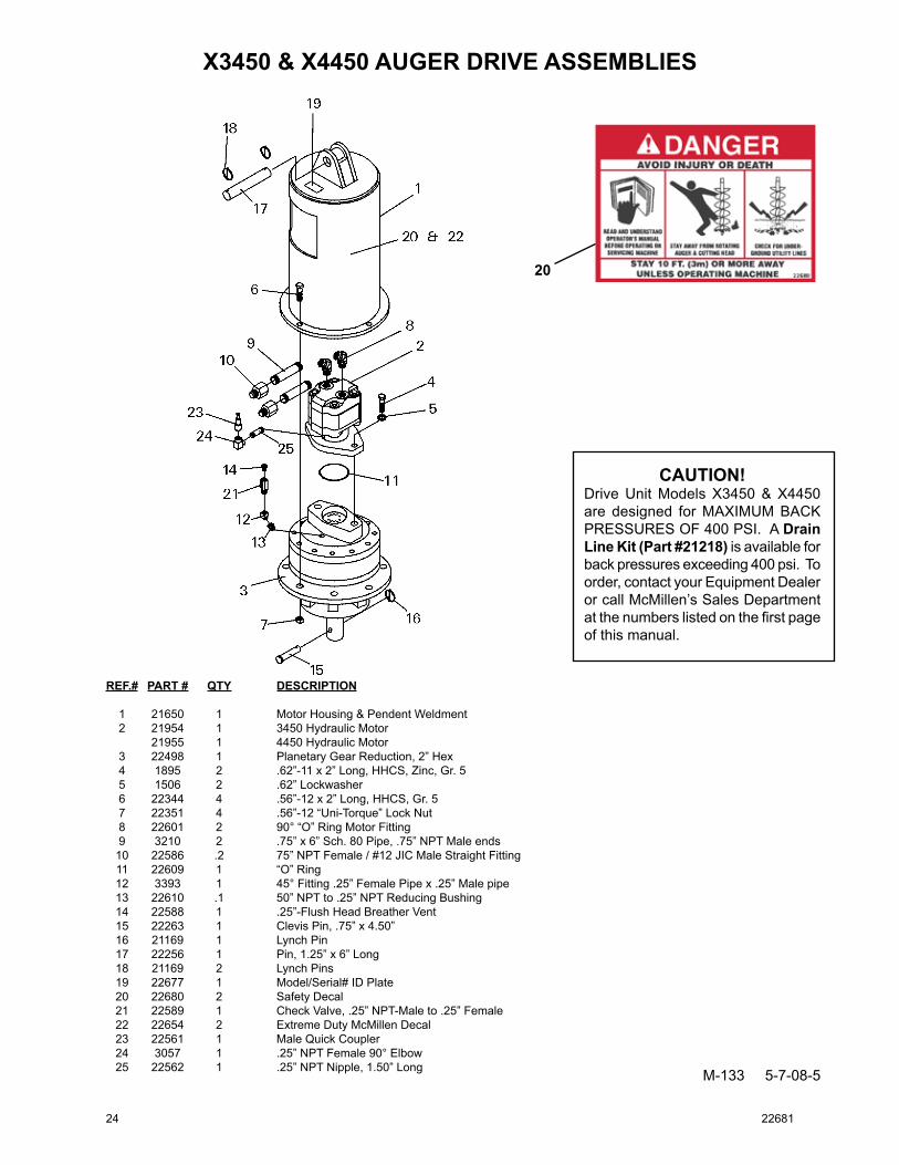
REF.# PART# QTY DESCRIPTION
1 21650 1 Motor Housing & Pendent Weldment 2 21954 1 3450 Hydraulic Motor 21955 1 4450 Hydraulic Motor 3 22498 1 Planetary Gear Reduction, 2” Hex 4 1895 2 .62”-11 x 2” Long, HHCS, Zinc, Gr. 5 5 1506 2 .62” Lockwasher 6 22344 4 .56”-12 x 2” Long, HHCS, Gr. 5 7 22351 4 .56”-12 “Uni-Torque” Lock Nut 8 22601 2 90° “O” Ring Motor Fitting 9 3210 2 .75” x 6” Sch. 80 Pipe, .75” NPT Male ends 10 22586 .2 75” NPT Female / #12 JIC Male Straight Fitting 11 22609 1 “O” Ring 12 3393 1 45° Fitting .25” Female Pipe x .25” Male pipe 13 22610 .1 50” NPT to .25” NPT Reducing Bushing 14 22588 1 .25”-Flush Head Breather Vent 15 22263 1 Clevis Pin, .75” x 4.50” 16 21169 1 Lynch Pin 17 22256 1 Pin, 1.25” x 6” Long 18 21169 2 Lynch Pins 19 22677 1 Model/Serial# ID Plate 20 22680 2 Safety Decal 21 22589 1 Check Valve, .25” NPT-Male to .25” Female 22 22654 2 Extreme Duty McMillen Decal 23 22561 1 Male Quick Coupler 24 3057 1 .25” NPT Female 90° Elbow 25 22562 1 .25” NPT Nipple, 1.50” Long
CAUTION!Drive Unit Models X3450 & X4450 are designed for MaXIMUM BaCk PRESSURES OF 400 PSI. a DrainLineKit(Part#21218) is available for back pressures exceeding 400 psi. To order, contact your Equipment Dealer or call McMillen’s Sales Department at the numbers listed on the first page of this manual.
X3450&X4450AUGERDRIVEASSEMBLIES
20
24 22681
X1455 & X1955 AUGER DRIVE ASSEMBLIESSERVICE PARTS
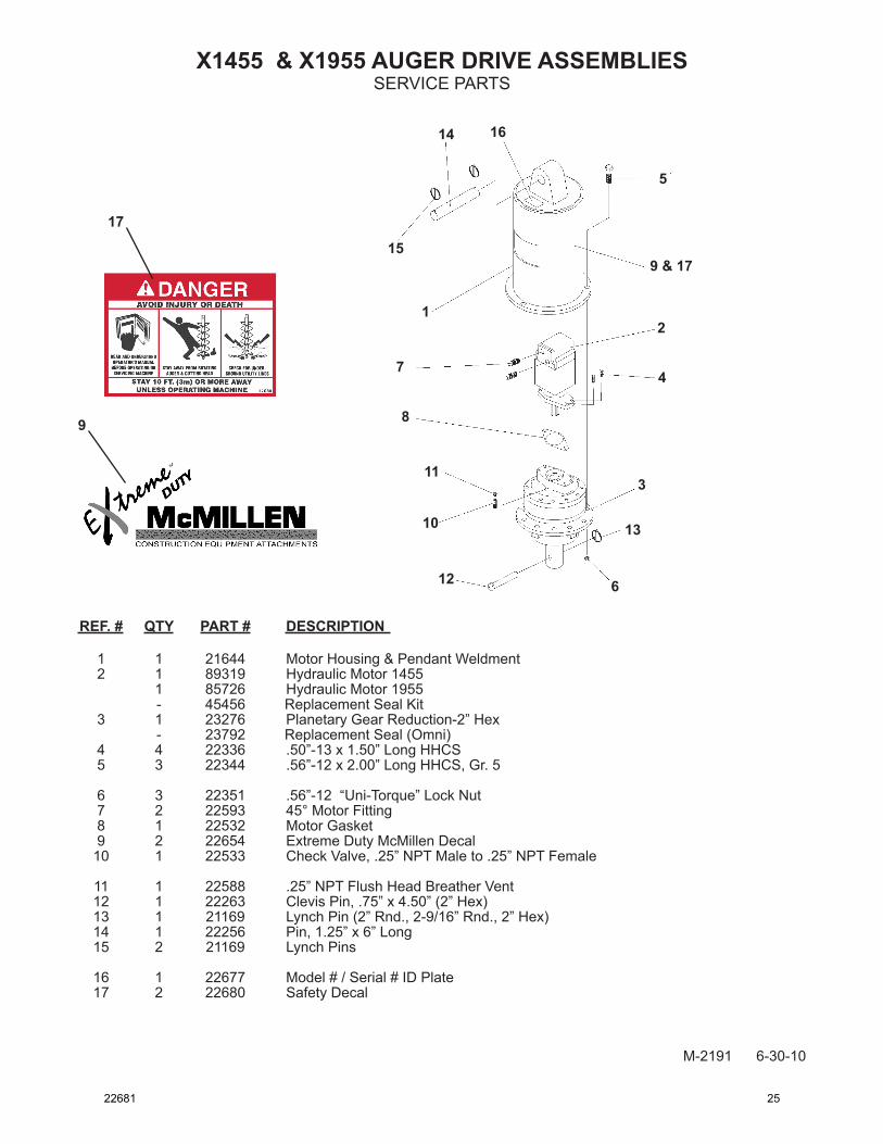
REF. # QTY PART # DESCRIPTION
1 1 21644 Motor Housing & Pendant Weldment 2 1 89319 Hydraulic Motor 1455 1 85726 Hydraulic Motor 1955 - 45456 Replacement Seal Kit 3 1 23276 Planetary Gear Reduction-2” Hex - 23792 Replacement Seal (Omni) 4 4 22336 .50”-13 x 1.50” Long HHCS 5 3 22344 .56”-12 x 2.00” Long HHCS, Gr. 5
6 3 22351 .56”-12 “Uni-Torque” Lock Nut 7 2 22593 45° Motor Fitting 8 1 22532 Motor Gasket 9 2 22654 Extreme Duty McMillen Decal 10 1 22533 Check Valve, .25” NPT Male to .25” NPT Female
11 1 22588 .25” NPT Flush Head Breather Vent 12 1 22263 Clevis Pin, .75” x 4.50” (2” Hex) 13 1 21169 Lynch Pin (2” Rnd., 2-9/16” Rnd., 2” Hex) 14 1 22256 Pin, 1.25” x 6” Long 15 2 21169 Lynch Pins
16 1 22677 Model # / Serial # ID Plate 17 2 22680 Safety Decal
M-2191 6-30-10
1614
15
5
9 & 17
2
3
4
13
612
10
11
8
7
9
17
1
22681 25

M-132 5-7-08-3
950, 1450, 1950, & 2450 AUGER DRIVE ASSEMBLIESSERVICE PARTS
REF. # QTY PART # DESCRIPTION
1 1 21645 Motor Housing & Pendant Weldment 2 1 21950 Hydraulic Motor 950 1 21956 Hydraulic Motor 1450 1 21952 Hydraulic Motor 1950 1 21953 Hydraulic Motor 2450 3 1 22495 Planetary Gear Reduction-2” Round 1 22496 Planetary Gear Reduction-2” Hex 1 22497 Planetary Gear Reduction-2 9/16” Round 4 4 22336 .50”-13 x 1.50” Long HHCS 6 3 22344 .56”-12 x 2.00” Long HHCS, Gr. 5 7 3 22351 .56”-12 “Uni-Torque” Lock Nut 8 2 22593 45° Motor Fitting 9 1 22532 Motor Gasket 10 2 22654 Extreme Duty McMillen Decal 11 1 22533 Check Valve, .25” NPT Male to .25” NPT Female 12 1 22588 .25” NPT Flush Head Breather Vent 13 1 22261 Clevis Pin, .62” x 4” (2” Round) 22262 Clevis Pin, .88” x 4.50” (2-9/16” Round) 22263 Clevis Pin, .75” x 4.50” (2” Hex) 14 1 21169 Lynch Pin (2” Rnd., 2-9/16” Rnd., 2” Hex) 15 1 22256 Pin, 1.25” x 6” Long 16 2 21169 Lynch Pins 17 1 22677 Model # / Serial # ID Plate 18 2 22680 Safety Decal
26 22681
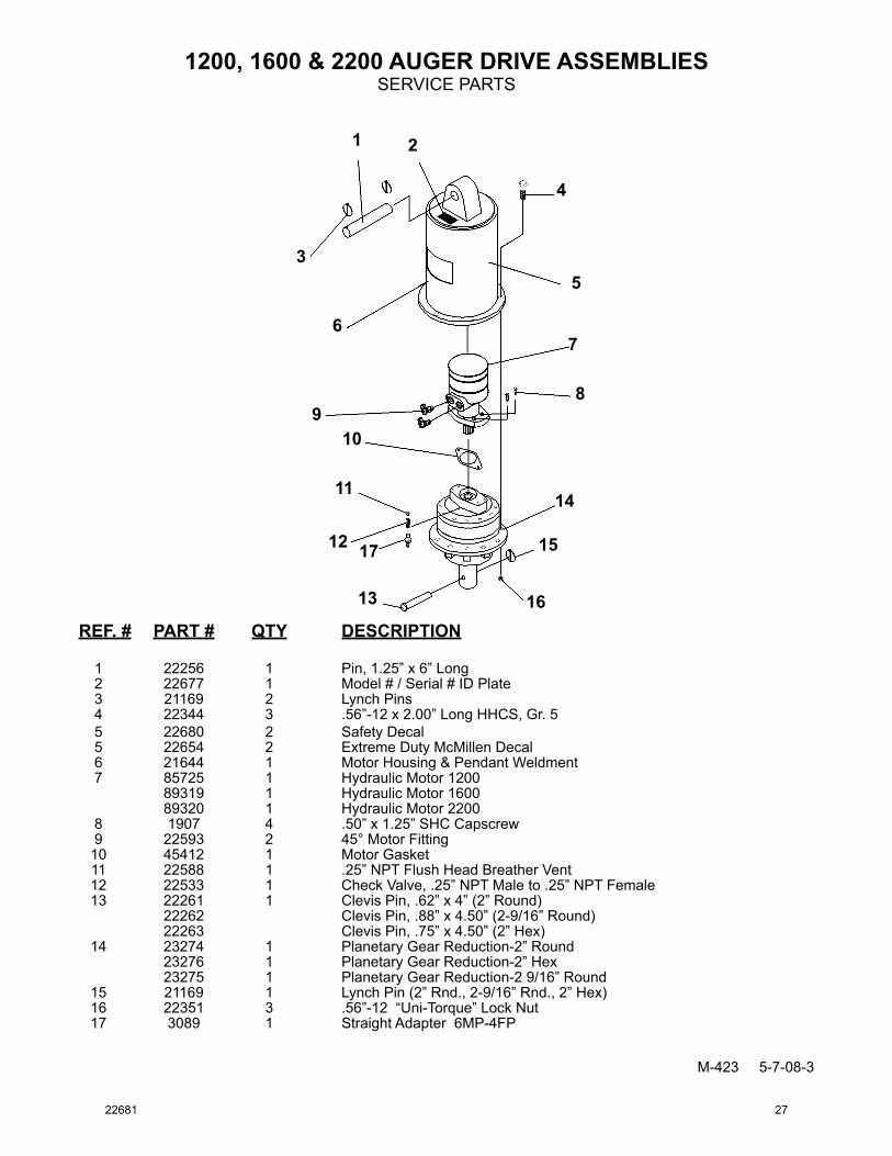
M-423 5-7-08-3
1200, 1600 & 2200 AUGER DRIVE ASSEMBLIESSERVICE PARTS
REF. # PART # QTY DESCRIPTION
1 22256 1 Pin, 1.25” x 6” Long 2 22677 1 Model # / Serial # ID Plate 3 21169 2 Lynch Pins 4 22344 3 .56”-12 x 2.00” Long HHCS, Gr. 5 5 22680 2 Safety Decal 5 22654 2 Extreme Duty McMillen Decal 6 21644 1 Motor Housing & Pendant Weldment 7 85725 1 Hydraulic Motor 1200 89319 1 Hydraulic Motor 1600 89320 1 Hydraulic Motor 2200 8 1907 4 .50” x 1.25” SHC Capscrew 9 22593 2 45° Motor Fitting 10 45412 1 Motor Gasket 11 22588 1 .25” NPT Flush Head Breather Vent 12 22533 1 Check Valve, .25” NPT Male to .25” NPT Female 13 22261 1 Clevis Pin, .62” x 4” (2” Round) 22262 Clevis Pin, .88” x 4.50” (2-9/16” Round) 22263 Clevis Pin, .75” x 4.50” (2” Hex) 14 23274 1 Planetary Gear Reduction-2” Round 23276 1 Planetary Gear Reduction-2” Hex 23275 1 Planetary Gear Reduction-2 9/16” Round 15 21169 1 Lynch Pin (2” Rnd., 2-9/16” Rnd., 2” Hex) 16 22351 3 .56”-12 “Uni-Torque” Lock Nut 17 3089 1 Straight Adapter 6MP-4FP
1 2
3
4
5
67
89
10
11
12
13
14
15
16
17
22681 27

M-804 2-15-10-3
Limited WarrantyExcept for the Excluded Products as described below, all new products are warranted to be free from defects in material and/or workmanship during the Warranty Period, in accordance with and subject to the terms and condi-tions of this Limited Warranty.
1. Excluded Products. The following products are excluded from this Limited Warranty:
(a) Any cable, part that engages with the ground (i.e. sprockets), digging chain, bearing, teeth, tamping and/or demolition head, blade cutting edge, pilot bit, auger teeth and broom brush that either constitutes or is part of a product.
(b) Any product, merchandise or component that, in the opinion of Paladin Light Construction1, has been (i) misused; (ii) modified in any unauthorized manner; (iii) altered; (iv) damaged; (v) involved in an accident; or (vi) repaired using parts not obtained through Paladin Light Construction.
2. Warranty Period. The Limited Warranty is provided only to those defects that occur during the Warranty Period, which is the period that begins on the first to occur of: (i) the date of initial purchase by an end-user, (ii) the date the product is first leased or rented, or (iii) the date that is six (6) months after the date of shipment by Paladin Light Construction as evidenced by the invoiced shipment date (the “Commencement Date”) and ends on the date that is twenty-four (24) months after the Commencement Date. (NOTE: The Planetary Gearbox ONLY carries an additional 3 years warranty.)
3. Terms and Conditions of Limited Warranty. The following terms and conditions apply to the Limited Warranty hereby provided:
(a) Option to Repair or Replace. Paladin Light Construction shall have the option to repair or replace the product.
(b) Timely Repair and Notice. In order to obtain the Limited Warranty, (i) the product must be repaired within thirty (30) days from the date of failure, and (ii) a claim under the warranty must be submitted to Paladin Light Construction in writing within thirty (30) days from the date of repair.
(c) Return of Defective Part or Product. If requested by Paladin Light Construction, the alleged defective part or product shall be shipped to Paladin Light Construction at its manufacturing facility or other location specified by Paladin Light Construction, with freight PRE-PAID by the claimant, to allow Paladin Light Construction to inspect the part or product.
Claims that fail to comply with any of the above terms and conditions shall be denied.
LIMITATIONS AND EXCLUSIONS.
THIS LIMITED WARRANTY IS IN LIEU OF ALL OTHER WARRANTIES, EXPRESS OR IMPLIED, INCLUDING WITHOUT LIMITATION THE WARRANTIES OF MERCHANTABILITY, FITNESS FOR A PARTICULAR PURPOSE AND ANY WARRANTY BASED ON A COURSE OF DEALING OR USAGE OF TRADE.
IN NO EVENT SHALL PALADIN LIGHT CONSTRUCTION BE LIABLE FOR CONSEQUENTIAL OR SPECIAL DAMAGES.
IN NO EVENT SHALL PALADIN LIGHT CONSTRUCTION BE LIABLE FOR ANY LOSS OR CLAIM IN AN AMOUNT IN EXCESS OF THE PURCHASE PRICE, OR, AT THE OPTION OF PALADIN LIGHT CONSTRUCTION, THE RE-PAIR OR REPLACEMENT, OF THE PARTICULAR PRODUCT ON WHICH ANY CLAIM OF LOSS OR DAMAGE IS BASED. THIS LIMITATION OF LIABILITY APPLIES IRRESPECTIVE OF WHETHER THE CLAIM IS BASED ON BREACH OF CONTRACT, BREACH OF WARRANTY, NEGLIGENCE OR OTHER CAUSE AND WHETHER THE ALLEGED DEFECT IS DISCOVERABLE OR LATENT.
1Attachment Technologies Inc., a subsidiary of Paladin Brands Holding, Inc. (PBHI) is referred to herein as Paladin Light Construction.
February 10, 2010
28 22681