
OPERATOR SELECTABLE THERMAL IT CURVE
15
Full Terms & Conditions of access and use can be found at https://www.tandfonline.com/action/journalInformation?journalCode=uemp20 Electric Machines And Power Systems ISSN: 0731-356X (Print) (Online) Journal homepage: https://www.tandfonline.com/loi/uemp19 MICROCONTROLLER BASED THREE-PHASE INDUCTION MOTOR PROTECTION RELAY WITH OPERATOR SELECTABLE THERMAL IT CURVE FEATURE K. PANDURANGAVITTAL , D. B. FAKRUDDIN , I. RAGHAVENDRA RAO & K. PARTHASARATHY To cite this article: K. PANDURANGAVITTAL , D. B. FAKRUDDIN , I. RAGHAVENDRA RAO & K. PARTHASARATHY (1998) MICROCONTROLLER BASED THREE-PHASE INDUCTION MOTOR PROTECTION RELAY WITH OPERATOR SELECTABLE THERMAL IT CURVE FEATURE, Electric Machines And Power Systems, 26:1, 13-26, DOI: 10.1080/07313569808955804 To link to this article: https://doi.org/10.1080/07313569808955804 Published online: 10 May 2007. Submit your article to this journal Article views: 175 View related articles
Transcript of OPERATOR SELECTABLE THERMAL IT CURVE
Full Terms & Conditions of access and use can be found athttps://www.tandfonline.com/action/journalInformation?journalCode=uemp20
Electric Machines And Power Systems
ISSN: 0731-356X (Print) (Online) Journal homepage: https://www.tandfonline.com/loi/uemp19
MICROCONTROLLER BASED THREE-PHASEINDUCTION MOTOR PROTECTION RELAY WITHOPERATOR SELECTABLE THERMAL IT CURVEFEATURE
K. PANDURANGAVITTAL , D. B. FAKRUDDIN , I. RAGHAVENDRA RAO & K.PARTHASARATHY
To cite this article: K. PANDURANGAVITTAL , D. B. FAKRUDDIN , I. RAGHAVENDRA RAO & K.PARTHASARATHY (1998) MICROCONTROLLER BASED THREE-PHASE INDUCTION MOTORPROTECTION RELAY WITH OPERATOR SELECTABLE THERMAL IT CURVE FEATURE,Electric Machines And Power Systems, 26:1, 13-26, DOI: 10.1080/07313569808955804
To link to this article: https://doi.org/10.1080/07313569808955804
Published online: 10 May 2007.
Submit your article to this journal
Article views: 175
View related articles
MICROCONTROLLER BASED THREE-PHASE INDUCTION MOTORPROTECTION RELAY WITH OPERATOR SELECTABLE THERMALI-T CURVE FEATURE
K. PANDURANGAVITTAL, D. B. FAKRUDDIN,and I. RAGHAVENDRA RAO
Department of Electrical EngineeringKarnataka Regional Engineering CollegeSrinivasnagar, India
K.PARTHASARATHY
Department of Electrical EngineeringIndian Institute of ScienceBangalore, India
ABSTRACT:
This paper presents a Microcontroller based three phase induction motor protectionrelay. The scheme employs the Hall effect current transducers for sensing motor linecurrents, and an 'Auto ranging' feature, in order to acquire motor line currentsaccurately from no load to blocked rotor current. The flexibility of 'Operator selectablethermal current versus time (1-T) curves feature' is incorporated in the relay software,in which using the operator fed cold curve points and the thermal time constant of themotor, the corresponding 1-T cold and hot curves can be fitted by the relay Software.The relay performance, with the selected 1-T curves has been studied in thelaboratory by testing on a three phase, 5 h.p. induction motor and it has been observedthat the relay to follow the selected1-T characteristics.
1. INTRODUCTION:
The three phase induction motors are widely used-as industrial drive motors. In orderto reduce the-size and to minimise the cost, large capacity motors are designed so that,the magnetic and current densities are close to the limiting levels. Such motors aresensitive to abnormal operating conditions like overvoltage or over loading etc. andhence require high speed and reliable protection scheme.
The digital relays based on microprocessors or microcontrollers can provide accuratehigh speed protection. Further, they can be programmed to follow a desired relaycharacteristic [ 1,2 ]. A Microcontroller has in-built features like timers, analog todigital converter (ADC) and digital input output (I/O) units along with centralprocessing unit (CPU). This results in reduced hardware for realising a real timecontroller and consequently improves reliability [3].
This paper presents Intel 8097BH microcontroller based protection scheme for threephase induction motor. The hardware scheme developed consists of input end halleffect current transducers in current channels, to enhance the bandwidth and
Request reprints from K. Pandurangavittal. Manuscript received in final form August 12, 1996.
Electric Machines and Power Systems, 26: 13-26, 1998Copyright e 1998 Taylor & Francis0731-356X/98 $12.00 + .00
13
K. PANDURANGAVITTAL ET AL.
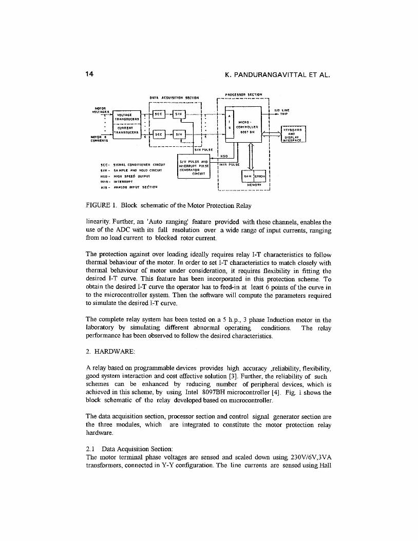
FIGURE 1. Block schematic of the Motor Protection Relay
linearity. Further, an 'Auto ranging' feature provided with these channels, enables the use of the ADC with its full re:solution over a wide range of input currents, rangtng from no load current to blocked rotor current.
The protection against over loading ideally requires relay I-T characteristics to follow thermal behaviour of the motor. In order to set I-T characteristics to match closely with thermal behaviour of motor under consideration, it requires flexibility in fitting the desired I-T curve. This feature has been incorporated in this protection scheme. To obtain the desired I-T curve the operator has to feed-in at least 6 points of the curve in to the rnicrocontroller system. Then the software will compute the parameters required to simulate the desired 1-T curve.
The complete relay system has been tested on a 5 h.p., 3 phase Induction motor in the laboratory by simulating dBc:rent abnormal operating conditions. The relay performance has been observed tlo follow the desired characteristics.
A relay based on programmable (devices provides high accuracy ,reliability, flexibility, good system interaction and cost effective solution [ 3 ] . Further, the reliability of such schemes can be enhanced by reducing number of peripheral devices, which is achieved in this scheme, by using Intel 8097BH microcontroller [4]. Fig. 1 shows the block schematic of the relay dleveloped based on microcontrollea.
The data acquisition section, pralcessor section and control signal generator section are the three modules, which are integrated to constitute the motor protection relay hardware.
2.1 Data Acquisition Section: The motor terminal phase voltages are sensed and scaled down using 230V/6V,3VA transformers, connected in Y-Y configuration. The line currents are sensed using Hall
MICROCONTROLLER BASED PROTECTION SCHEME
- - I - - - - - - - - - - - -7- -----------
I 1 I I
PRIMARY I
! CURRENT I D
I SECONDARY
! WlNDlNG
CURRENT I
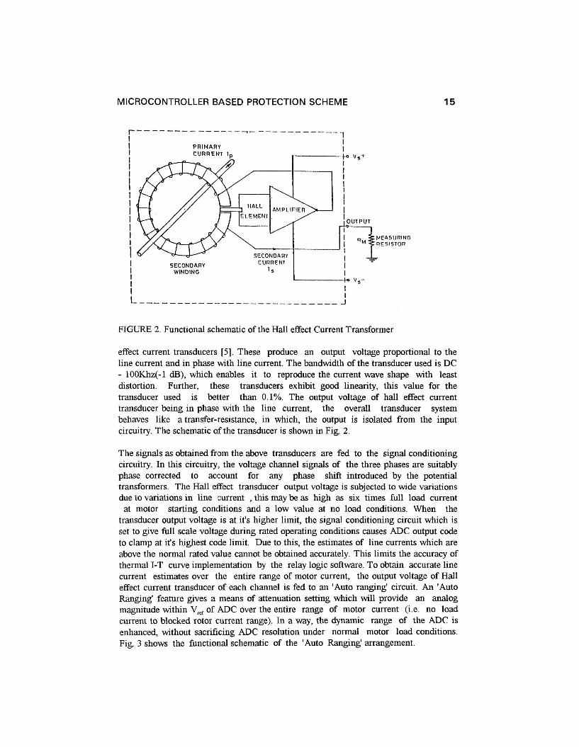
FIGURE 2. Functional schematic of the Hall effect Current Transformer
effect current transducers [ 5 ] . These produce an output voltage proportional to the line current and in phase with line current. The bandwidth of the transducer used is DC - 100Khz(-1 dB), which enables it to reproduce the current wave shape with least distortion. Further, these transducers exhibit good linearity, this value for the transducer used is better than 0.1%. The output voltage of hall effect current transducer being in phase with the line current, the overall transducer system behaves like a transfer-resistance, in which, the output is isolated from the input circuitry. The schematic of the transtiucer is shown in Fig. 2.
The signals as obtained from the above transducers are fed to the signal conditioning circuitry. In this circuitry, the voltage channel signals of the three phases are suitably phase corrected to account for any phase shift introduced by the potential transformers. The Hall eEect transducer output voltage is subjected to wide variations due to variations in line current , this may be as high as six times full load current
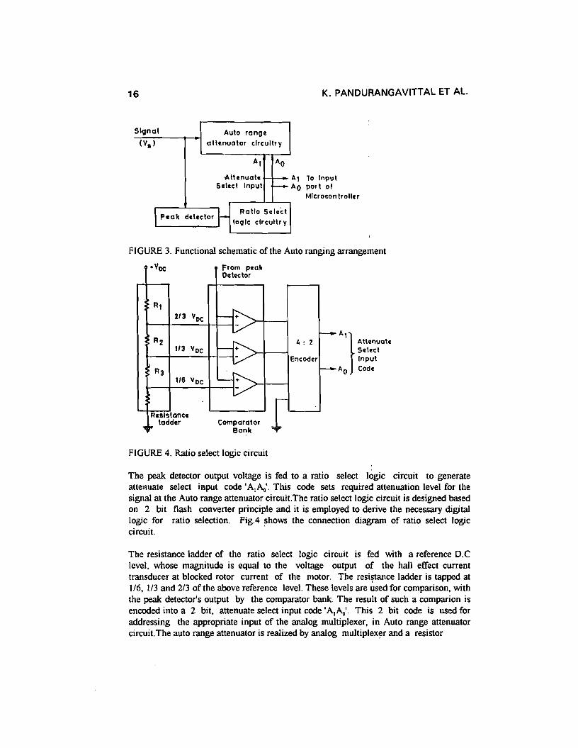
at motor starting contiitions ancl a low value at no load conditions. When the transducer output voltage is at it's higher limit, the signal conditioning circuit which is set to gve full scale voltage during rated operating conditions causes ADC output code to clamp at it's highest code limit. Due to this, the estimates of line currents which are above the normal rated value cannol. be obtained accurately. This limits the accuracy of thermal I-T curve implenientation by the relay logic software. To obtain accurate line current estimates over the entire range of motor current, the output voltage of Hall effect current transducer of each channel is fed to an 'Auto rangingq circuit. An 'Auto Rangng' feature gves a means of ;attenuation setting which will provide an analog magnitude within V,, of ADC over the entire range of motor current (i.e. no load current to blocked rotor current range). In a way, the dynamic range of the ADC is enhanced, without sacrificing ADC resolution under normal motor load conditions. Fig. 3 shows the functional schematic of the 'Auto Ranging' arrangement.
16 K. PANDURANGAVITTAL ET AL.
Signal Aula range(V. ) allenualor circuitry
AI AO
.Allenuale -S.I«1 Inpul --IP.ak dol«lor l- Ralfo S.I.ct
logic clrcultr y
Al To InpulAO port of
Mlcrocon Iroller
AI}All.nualoS.loclInpul
AO Cod.
• DC From p.akO.t«lor
RI
~2/3 YDC -R2
~~ : 2
1/3 YecEncoder
R3
~r-
1/6 Vec
r-
Rulstanc.,,.. ladd.r Comparator
~lo"Bank
FIGURE 3. Functional schematic of the Auto ranging arrangement
V
FIGURE 4. Ratio select logic circuit
The peak detector output voltage is fed to a ratio select logic circuit to generateattenuate select input code 'A,P.o'. This code sets required attenuation level for thesignal at the Auto range attenuator circuit.The ratio select logic circuit is designed basedon 2 bit flash converter principle and it is employed to derive the necessary digitallogic for ratio selection. Fig.4 shows the connection diagram of ratio select logiccircuit.
The resistance ladder of the ratio select logic circuit is fed with a reference D.Clevel, whose magnitude is equal to the voltage output of the hall effect currenttransducer at blocked rotor current of the motor. The resistance ladder is tapped at1/6, 1/3 and 2/3 of the above reference level. These levels are used for comparison, withthe peak detector's output by the comparator bank. The result of such a comparion isencoded into a 2 bit, attenuate select input code 'A,P.o'. This 2 bit code is used foraddressing the appropriate input of the analog multiplexer, in Auto range attenuatorcircuit.The auto range attenuator is realized by analog multiplexer and a resistor
MICROCONTROLLER BASED PROTECTION SCHEME 17
Voutput
Vs 0
Ra1/3 Vs
1 ~: 1
RbAnalog
1/~ VsMuillpl exer
20
Rc116 Vs
3
Rd All.nuat.S.loct Input
.,. 1 1Al AO
FIGURE 5. Auto range Attenuator circuit
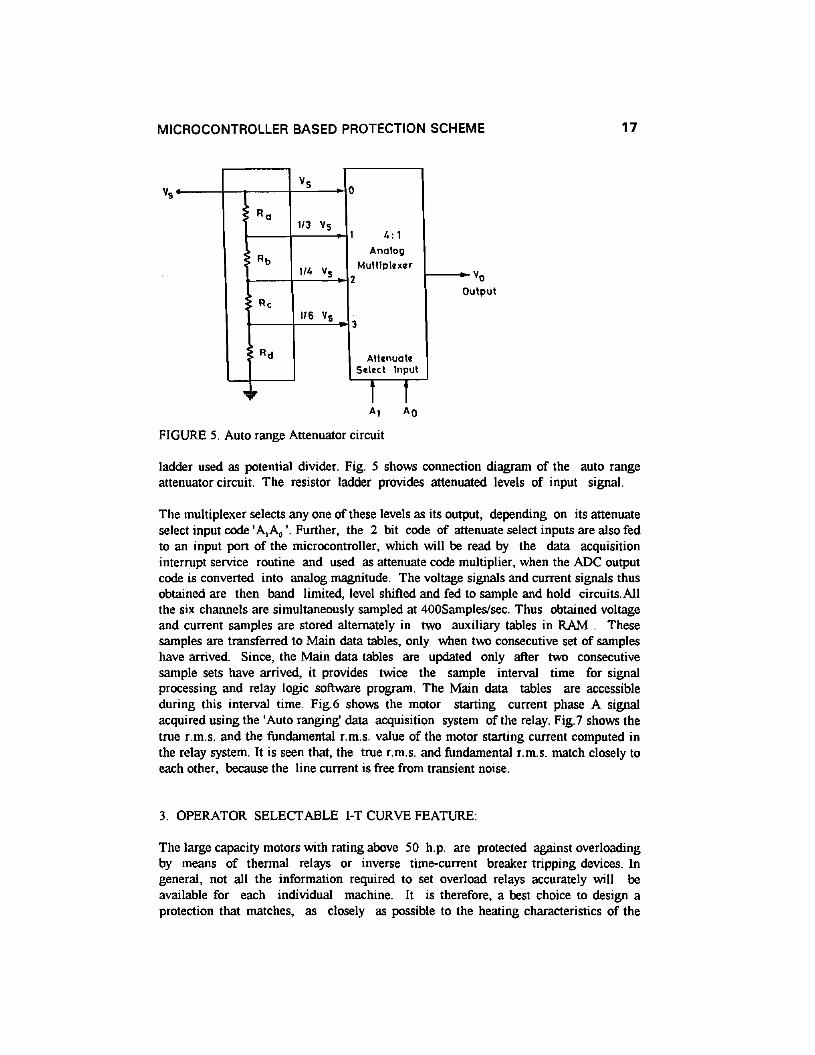
ladder used as potential divider. Fig. 5 shows connection diagram of the auto rangeattenuator circuit. The resistor ladder provides attenuated levels of input signal.
The multiplexer selects anyone of these levels as its output, depending on its attenuateselect input code 'A,A" '. Further, the 2 bit code of attenuate select inputs are also fedto an input port of the microcontroller, which will be read by the data acquisitioninterrupt service routine and used as attenuate code multiplier, when the ADC outputcode is converted into analog magnitude. The voltage signals and current signals thusobtained are then band limited, level shifted and fed to sample and hold circuits.Allthe six channels are simultaneously sampled at 400Sampleslsec. Thus obtained voltageand current samples are stored alternately in two auxiliary tables in RAM. Thesesamples are transferred to Main data tables, only when two consecutive set of sampleshave arrived. Since, the Main data tables are updated only after two consecutivesample sets have arrived, it provides twice the sample interval time for signalprocessing and relay logic software program. The Main data tables are accessibleduring this interval time. Fig.6 shows the motor starting current phase A signalacquired using the 'Auto ranging' data acquisition system of the relay. Fig.7 shows thetrue r.m.s. and the fundamental r.m.s. value of the motor starting current computed inthe relay system. It is seen that, the true r.m.s. and fundamental r.m.s. match closely toeach other, because the line current is free from transient noise.
3. OPERATOR SELECTABLE I-T CURVE FEATURE:
The large capacity motors with rating above 50 h.p. are protected against overloadingby means of thermal relays or inverse time-current breaker tripping devices. Ingeneral, not all the information required to set overload relays accurately will beavailable for each individual machine. It is therefore, a best choice to design aprotection that matches, as closely as possible to the heating characteristics of the

K. PANDURANGAVITTAL ET AL.
-8000 , ~ ~ ~ ~ r ~ ~ ' ' l ~ r ' ~ ' ~ r ~ ~ 1 1 ~ ' ' ~ ~ ' ~ " r r ~ 7 4
0.00 3.05 0.10 0.1 5 T ~ m e ID Secs.
FIGURE 6.Motor starting current signal acquired through 'Auto rangng' data acquisition system
. - - - ----- True R.M.S. magnitude
Fundomenta l R.M.S.
4
Time in Secs.
FIGURE 7. Motor starting curre:nt computed in relay system
motor under consideration, and a flexibility to mod@ the relay characteristic by the operator to achieve best protection. The heating in the machine is due to the combined effect of both positive and negative sequence currents. Therefore, a scheme wherein, the relay is made to be responsive to an equivalent 'thermal current', which reflects the total heating in the machine will be adequate [6]. The thermal current is gven by,
Where, I = thermal cl~rrent, I, == Positive sequence current , 4 = Negative sequence current, K,, = a constant , set between 1.5 to 6 to account the increased resistance in the motor winding due to skin effect.

MICROCONTROLLER BASED PRCITECTION SCHEME 19
The thermal model of the motor can be given in the form of a time - current relationshp, in whch the time value represents the time taken for the temperature of the motor to rise to it's maximum permissible value, with the specified steady state current flowing though it. A gener,al curve for thermal electrical relays, based on heating effect, assuming the motor was started from cold condition is speclfied by IEC recommendation 25 5-8 as,
where , t = operating time of the relay, T = thermal time constant, I = relay current, I, = Rated current, K = a constant by vvhich I is to be multiplied to obtain the current value to which the accuracy of the current is referred. Then, with regard to preheating on a relay with total memory function, the Hot curve is relevant and speczed by equation,
Where I, = speclfied load current before the overload occurs.
The cold curve and hot curve resulting out of equation ( 2 ) and (3) respectively are incorporated in the relay software. The I - T curves are fitted based on a techtuque reported by Schweiltzer et all. [7]. In t h s method, when the thermal current (I) exceeds pickup value, a weighted cumulative summation of the thermal current is
carried out. when the result of this cumulative summation crosses a particular threshold (T,) , the relay issues a trig signal. For a chosen Tv , two constants a and P are employed such that the process of cumulative summation yields operating times that match as closely to those given l ~ y the desired operating characteristics. The summation is gven by equation (4).
SK+~ = SK + ~ 1 - 13 --------- '(4)
where, S,,= magnitude of the cumulsitive summation at (K+ l)'h sampling point, 1 = Magnitude of the motor thermal current at the (K+l)'h sampling instant.
The thermal current range over which I-T characteristics have to be fitted, requires sectionalisation of the curve in to two or more sections. For each section of curve to be fitted one set of a, 63 constants are employed to keep up accuracy constraint of curve fitting. The number of sections and associated a, psets will be more if higher accuracy is desired.
The operator selectable I-T curve feature employs fixed threshold value and fixed accuracy constraint for curve fitting. The operator has to enter the following data at the specified memory location of the relay readwrite memory (RAM), 0 The total number of points con the cold curve,that he is intending to enter (up to 6
points,this can be increased by sultable change in software). 0 The current magnitudes for the above selected points. 0 Correspondmg operating-times for the current magnitudes entered above. 0 Thermal time constant of the Motor.

20 K. PANDURANGAVITTAL ET AL.
o Full load current rating of the motor.o Pick-up current for the relay.Once the above data entry is over, the software, estimates the intermediate cold curvepoints by linear interpolation and these interpolated curve points are stored in currentand operating-time tables. In order to incorporate the 1-T characteristics by summationequation, it is required to determine number of sections required, range limits of
sections and corresponding a ,13 constants, keeping accuracy criteria in view. Thisis done by successive interval reduction technique. At. first step, the process of
computing a, 13 is based on points (I, ,t ,) and (I n ,t n ) [first and last points of I-Tcurve] and the associated equations (5) and (6) are,
(a.!] -13).t1 =Tv.2.M(a.l" -13).t ll =Tv.2.Mwhere 6t = sampling interval.
---------->(5)
---------->(6)
Equations 5 and 6 are then solved simultaneously to yield a and 13. This a and 13 areused in computing t, at intermediate intervals of I and accuracy of fitting is verifiedby using corresponding 't' from operating time table. If required accuracy of fitting is
not met, then a , 13 are recomputed with (I, ,t , ) as section start point, (I 0-' ,t 0-1 ) assection end point. This process of section end point shift is done in steps as, (I 0-2 ' t"..2 ),
(In-' ,I.., ) ..... so on. Fig. 8 depicts this scheme of calculation. At. every step, a ,13constants valid for the section is computed and curve fit accuracy is verified for thatsection. If all the points of the curve section are well fitted, then that section end pointthermal current will be known. In this way, end point of the section is determined and
recomputed value of a and 13 constants with this start and end points gives best fittingfor the section of the curve. Similar way other sections of the curve are identified with
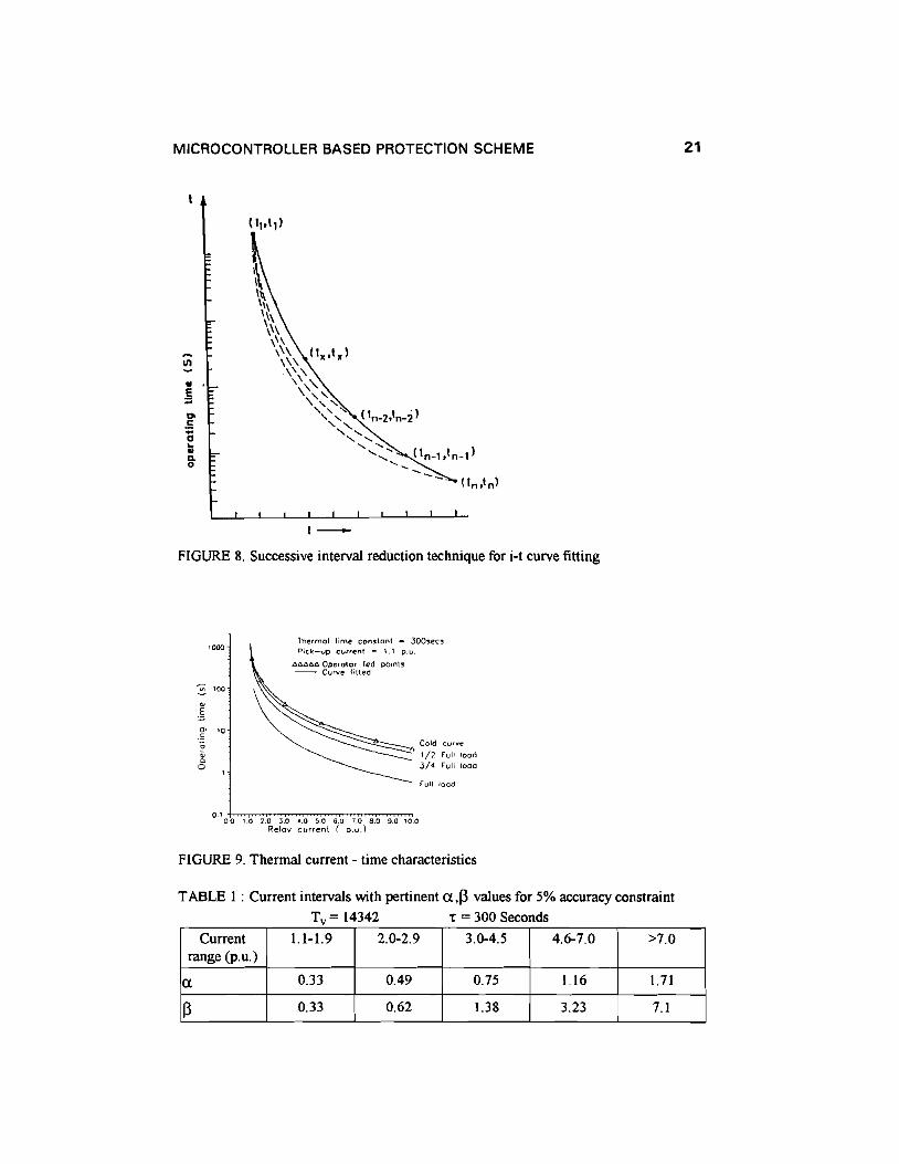
associated a. 13 sets. Fig.9 shows the thermal current - time characteristics fittedusing operator fed cold curve points. Fig. 10 shows the flow chart for the operator
selectable 1-T characteristics curve fitting subprogram. Table 1 shows computed a,13values valid over intervals of thermal current expressed in p.u,
Once the cold curve is fitted based on operator fed data, the relay softwaredetermines the initial counts required for the summation counter, in order toincorporate hot curves. Hot curves for 1/2 Full load, 3/4 Full load and Full loadpreheating conditions are fitted by the relay software and shown in Fig.ct. Table 2indicates the hot curve initial count values for SK counter. Under motor runningcondition, the relay software will be computing thermal current and if thermal overloadoccurs (i.e. if relay picks-up) then it selects the initial SK count automatically based
on pre load condition as per Table2. Then follows the summation equation with the newinitial count. If the thermal overload current falls below the pickup value, the reset of therelay is performed. A linear reset characteristic is obtained using the equation (7) and
the summation counter is decremented to zero for reset.
----------->(7)
MICROCONTROLLER BASED PROTECTION SCHEME
VI
'".5ii~..D.o
1-
FIGURE 8. Successive interval reduction technique for i-t curve fitting
21
"00
~ too.1o- '0so
"Qo
Thermal lime constant = 300sec,Pic~-vp current = 1.1 o.u.
Ll.6A6L1o Operator fed co.ots- Curve fitted
Cold curve
1/2 Full load
3/4 Full 1000
Full load
0.1 o*o~,o~,O::.o~'''.o''"'""''O::o"':>"'.o~e.~o'"':''''0~8''.0~9'''.0""'''0.0Relay current ( D.U.)
FIGURE 9. Thermal current - time characteristics
TABLE 1 : Current intervals with pertinent a,13 values for 5% accuracy constraint
Tv = 14342 r = 300 Seconds
Current 1.1-1.9 2.0-2.9 3.0-4.5 4.6-7.0 >7.0range (p.u.)
a 0.33 0.49 0.75 1.16 1.71
13 0.33 0.62 1.38 3.23 7.1

22 K. PANDURANGAVITTAL ET AL.
TABLE 2' Initial count for SK counter to fit-in Hot curvesPredisturbance Thermal Inital count for Sk countercurrent
1/2 Full load 3,003
3/4 Full load 6,769
Full load 12,060
Read number of points, I, T for the points selected. Interpolate intermediatepoints and store results in I,T tables. Set starting point pointer CSTP) = Firstpoint on interpolation table. Set ending point poinnter (ENP) = Last point oninterpolation table. Compute «, [3 with I,T at STP and ENP.Set interpolation table pointer (ITP) = STP
Compute operating time = Tco= (T v2.ilt)/(alm -(3)
Set ENP = ENP--IITP=STPCompute «,[3
with I,T at ITP,ENP
N
Store «,[3 in tables, STP, ENP in valid section Table
y
Set STP= ENP+ I,ENP = Interpolationtable last address
FIGURE 10. I-T Characteristics curve fitting subprogram
4. RELAY SOFTWARE:
The motor protection relay scheme has several protection functions integrated in it bymeans of software. The protection functions integrated are, thermal overloadprotection, voltage unbalance protection, prolonged starting protection, blocked

MICROCONTROLLER BASED PROTECTION SCHEME 23
rotor protection, earth fault protection,over voltage and under voltage protection. Therelay logic software computes sine and cosine components of line current byemploying Full cycle window Fourier algorithm as per equations (8) and (9).
Ipsm = H(lPJ -IP7) + 0.707 1(In +Ip4-IP6 -11'8)
Ipr=; = H(lPI -Ip5)+ 0.7071(ln -Ip4 -IP6 +11'8)
--------->(8)
--------->(9)
Where, 1p sin and 1p cos are respectively the fundamental sine and cosinecomponents of the line current in phase 'p'.
The 1PI .l1'8 are current samples of phase 'p' ,available in Main data table.
The quadrature components of the positive, negative, and zero sequence currentsare obtained from the sine and cosine components of the individual line currents byapplying symmetrical components transformation [8). The equations (10) to (15) giveexpressions for the peak values of the sine and cosine components of the sequencecurrents.
ltSlN = tVasm - 0.5(hsin + Iesm) - 0.866(hr=; -Ier=;)
IICOS = tVacos - 0.5(lbcos + Ier=;) + 0.866(hsm -Iesm)
l ism = tVasm - 0.5(hsin +Iesm) +0.866(hr=; -Ier=;)
lscos = tVacos - 0.5(hr=; + Iecos) - 0.866(hsm -Iesm)
IOSlN =kVasm +hsin +Iesm
locos = kVacos +hcos +Ier=;
---------->( I0)
----------->( II)
----------->(12)
------------>(13)
------------>(14)
------------>(15)
The peak values of sequence components are then computed using equations (16) to(18) as,
10 =JI~SlN + I~cos
----------->(16)
----------->( 17)
----------->(18)
Fig. I I shows complete sequence of the relay logic program incorporated in this scheme.The motor protection relay based on above scheme was tested on line, with 5 h.p.,400V,50Hz, Delta connected, three phase induction motor at the laboratory. The
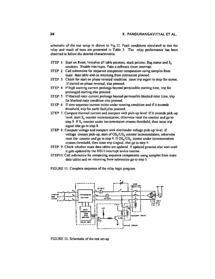
24 K. PANDURANGAVITTAL ET AL.
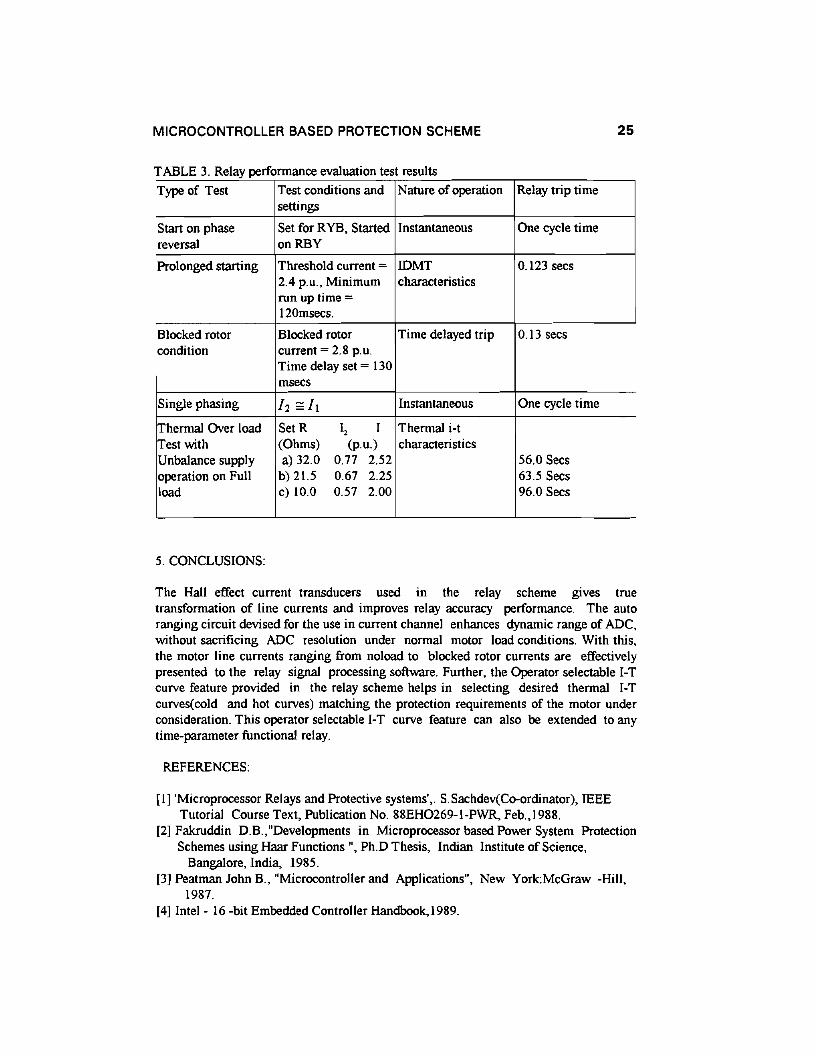
schematic of the test setup is shown in Fig.12. Fault conditions simulated to test therelay and result of tests are presented in Table 3. The relay performance has beenobserved to follow the desired characteristics.
STEP I: Start on Reset, Initialise all table pointers, stack pointer, flag status and SKcounters. Enable interrupts. Fake a software timer interrupt.
STEP 2: Call subroutine for sequence component computation using samples frommain data table and on returning from subroutine proceed.
STEP 3: Check for start on phase reversal condition. Issue trip siganl to stop the motor,if started on phase reversal, else proceed.
STEP 4: If high starting current prolongs beyond permissible starting time, trip forprolonged starting else proceed.
STEP 5: Ifblocked rotor current prolongs beyond permissible blocked rotor time, tripfor blocked rotor condition else proceed.
STEP 6: If zero sequence current exists under running condition and if it exceedsthreshold, trip for earth fault,else proceed.
STEP 7: Compute thermal current and compare with pick-up level. If it exceeds pick-uplevel, start SK counter incrementation, otherwise reset the counter and go tostep 8. If SK counter under incrementaion crosses threshold, then issue tripsignal else go to step 8.
STEP 8: Compute voltage and compare with over/under voltage pick-up level. Ifvoltage crosses pick-up, start of OSKIUSK counter incrementation, otherwisereset the counter and go to step 9. IfOSKIUSK ounter under incrementationcrosses threshold, then issue trip singnal, else go to step 9.
STEP 9: Check whether main data tables are updated. Ifupdated proceed else wait until. it gets updated by the HSI.0 interrupt sevice routine.
STEPlO: Call subroutine for computing sequence components using samples from maindata tables and on returning from subroutine go to step 5.
FIGURE II. Complete sequence of the relay logic program
....IN
}-_.J.-~-----L-"""t"":'~·1 ~yH-'-,L--'{!O.IOJA t I
I I I '.".400'1
Ir,---------;;,.,-- r--' I I 1""OIlPM
I or. t 'ph I. N.
.OATA I I +1" : I :, L I"""'''''ON I I I , __..J
••0 ~ I
I CPU Sf '1 I '''WIll'''''' All'"SUTtON TA [1. '001 t I II I 111001 I L. __J
L__~I:~~I~_J I iDAlllt" CIAcunL ---J
FIGURE 12. Schematic of the test set-up
MICROCONTROLLER BASED PROTECTION SCHEME
TABLE 3 Relay performance evaluation test results
25
Type of Test Test conditions and Nature of operation Relay trip timesettings
Start on phase Set for RYB, Started Instantaneous One cycle timereversal onRBY
Prolonged starting Threshold current = IDMT 0.123 sees2.4 p.u., Minimum characteristicsrun up time =120msecs.
Blocked rotor Blocked rotor Time delayed trip 0.13 seescondition current = 2.8 p.u.
Time delay set = 130msecs
Single phasing 12 st, Instantaneous One cycle time
Thermal Over load SetR I, I Thermal i-tTest with (Ohms) (p.u.) characteristicsUnbalance supply a) 32.0 0.77 2.52 56.0 Secsoperation on Full b) 21.5 0.67 2.25 63.5 Secsload c) 10.0 0.57 2.00 96.0 Secs
5. CONCLUSIONS:
The Hall effect current transducers used in the relay scheme gives truetransformation of line currents and improves relay accuracy performance. The autoranging circuit devised for the use in current channel enhances dynamic range of ADC,without sacrificing ADC resolution under normal motor load conditions. With this,the motor line currents ranging from noload to blocked rotor currents are effectivelypresented to the relay signal processing software. Further, the Operator selectable 1-Tcurve feature provided in the relay scheme helps in selecting desired thermal 1-Tcurves(cold and hot curves) matching the protection requirements of the motor underconsideration. This operator selectable 1-T curve feature can also be extended to anytime-parameter functional relay.
REFERENCES:
[I] 'Microprocessor Relays and Protective systems'; S.Sachdev(Co-ordinator), IEEETutorial Course Text, Publication No. 88EH0269-I-PWR, Feb.,1988.
[2] Fakruddin D.B.,"Developments in Microprocessor based Power System ProtectionSchemes using Haar Functions", Ph.D Thesis, Indian Institute of Science,
Bangalore, India, 1985.[3] Peatman John B., "Microcontroller and Applications", New York:McGraw -Hill,
1987.[4] Intel - 16 -bit Embedded Controller Handbook, 1989.
26 K. PANDURANGAVITTAL ET AL.
[5) LEM S.A, Geneva, Product Specification, LEM LA-50-P.[6) IEC Specifications 255 - 8, "Thermal Electrical Relays".[7) Schweitzer E.O. and A1iagaA., "Programmable Time Parameter Relay Offers
Versatility and Accuracy", IEEE Transactions on Power Apparatus and Systems,Vol.PAS - 99, No.1, pp.152 -157, Jan/Feb 1980.
[8) A.G.Phadke, T.H1ibka, M.1brahim and M.S.Admiak, 'A microprocessor basedSymmetrical component distance relay', Power Industry ComputerApplications Conference, 1979, IEEE publications Conference, IEEEpublications NO.70C 301 - 3 PWR, pp,47 - 55,1979.