Operator Handbook for an STC UTC System - Home - …€¦ · · 2017-02-07Operator Handbook for...
366
Operator Handbook for an STC UTC System 666/HB/16940/000 666/HB/16940/000 Issue 35-3 Page: i Siemens Mobility, Traffic Solutions Sopers Lane POOLE Dorset BH17 7ER SYSTEM/PROJECT/PRODUCT: STC UTC Operator Handbook for an STC UTC System This is an unpublished work the copyright in which vests in Siemens plc. All rights reserved. The information contained herein is the property of Siemens plc and is supplied without liability for errors or omissions. No part may be reproduced or used except as authorised by contract or other written permission. The copyright and the foregoing restriction on reproduction and use extend to all the media in which this information may be embodied.
Transcript of Operator Handbook for an STC UTC System - Home - …€¦ · · 2017-02-07Operator Handbook for...

Operator Handbook for an STC UTC System 666/HB/16940/000
666/HB/16940/000 Issue 35-3 Page: i
Siemens Mobility, Traffic SolutionsSopers LanePOOLEDorsetBH17 7ER
SYSTEM/PROJECT/PRODUCT: STC UTC
Operator Handbook
for an
STC UTC System
This is an unpublished work the copyright in which vests in Siemens plc. All rights reserved.
The information contained herein is the property of Siemens plc and is supplied withoutliability for errors or omissions. No part may be reproduced or used except as authorised bycontract or other written permission. The copyright and the foregoing restriction onreproduction and use extend to all the media in which this information may be embodied.

Operator Handbook for an STC UTC System 666/HB/16940/000
666/HB/16940/000 Issue 35-3 Page: ii
ISSUE STATENote: Source of documents is shown under Type as below.
1=Paper, 2=VAX, 3=Microfilm, 4=CALTEXT Disc, 5=DECmate Disc,6=Paper Insert, 7=MAC Disc, 8=LIFESPAN, 9=SUN,10=AutoManager Meridian.
The document comprises the following components:
Pages CurrentIssue
Type Part ID File ID
All 34 10 666HB16940000 hb16940_V34-final.docx

Operator Handbook for an STC UTC System 666/HB/16940/000
666/HB/16940/000 Issue 35-3 Page: iii
CONTENTS1. INTRODUCTION .................................................................................................. 6
1.1 Purpose .............................................................................................................................................. 6
1.2 Scope .................................................................................................................................................. 6
1.3 Related documents ............................................................................................................................ 61.3.1 Parent Documents ...................................................................................................................... 61.3.2 Kindred Documents ................................................................................................................... 61.3.3 Reference Documents ................................................................................................................ 7
1.4 Definitions ......................................................................................................................................... 7
1.5 Issue state and amendment ............................................................................................................... 7
1.6 System Facility Licenses .................................................................................................................... 9
2. GENERAL DESCRIPTION ................................................................................ 102.1 Logging in to the System ................................................................................................................. 10
2.1.1 Logging in via the MMI Interface ............................................................................................. 102.1.2 Logging in via a Terminal Server ............................................................................................. 10
3. TERMINAL USE................................................................................................. 123.1 Keyboard Use .................................................................................................................................. 12
3.1.1 Common Keys ......................................................................................................................... 123.1.2 Keys for Non-MMI terminals ................................................................................................... 13
3.2 Command Line Editing ................................................................................................................... 14
3.3 Shortcut Command Entry............................................................................................................... 15
4. CASTS - "COMMANDS ACTIONED AND STORED TOGETHER" .................. 165. MAN MACHINE INTERFACE ............................................................................ 17
5.1 Starting a Session ............................................................................................................................ 17
5.2 Use of the Mouse ............................................................................................................................. 17
5.3 Menus .............................................................................................................................................. 175.3.1 Menu Options .......................................................................................................................... 185.3.2 OK........................................................................................................................................... 195.3.3 Apply....................................................................................................................................... 195.3.4 Default ..................................................................................................................................... 195.3.5 Cancel ..................................................................................................................................... 19
5.4 Windows .......................................................................................................................................... 19
5.5 Help ................................................................................................................................................. 19
5.6 Commands....................................................................................................................................... 205.6.1 Command Entry Menu Option .................................................................................................. 205.6.2 Command Entry Window ......................................................................................................... 205.6.3 Confirm ................................................................................................................................... 215.6.4 Listing Window ....................................................................................................................... 21
5.7 Graphics .......................................................................................................................................... 215.7.1 Introduction ............................................................................................................................. 215.7.2 Map Display Menu Option ....................................................................................................... 215.7.3 Edit .......................................................................................................................................... 215.7.4 Symbols ................................................................................................................................... 225.7.5 Map Menu ............................................................................................................................... 225.7.6 File .......................................................................................................................................... 225.7.7 Loading New Pictures .............................................................................................................. 22

Operator Handbook for an STC UTC System 666/HB/16940/000
666/HB/16940/000 Issue 35-3 Page: iv
5.8 Messages .......................................................................................................................................... 235.8.1 Message Entry Window ........................................................................................................... 235.8.2 Message Options Window ........................................................................................................ 235.8.3 Message Entry Window ........................................................................................................... 245.8.4 New Output Window Menu Option .......................................................................................... 245.8.5 System Message Menu Option ................................................................................................. 255.8.6 SCOOT Message Menu Option ................................................................................................ 255.8.7 Faults ....................................................................................................................................... 25
6. MAP EDITOR AND DISPLAY ............................................................................ 266.1 MMI Facilities ................................................................................................................................. 26
6.2 Non-MMI Facilities ......................................................................................................................... 26
7. CONSTRUCTION AND USE OF TIME-DISTANCE DIAGRAMS ...................... 277.1 General Description ........................................................................................................................ 27
7.2 Modes of operation .......................................................................................................................... 27
7.3 Setting Up Diagrams ....................................................................................................................... 28
7.4 Predicting Stage Timings ................................................................................................................ 29
7.5 Monitoring Current Stage Timings ................................................................................................ 29
7.6 Facilities common to both display modes........................................................................................ 30
7.7 TDDD Command Summary ........................................................................................................... 30
8. ENHANCED FAULT LISTING FILTER .............................................................. 338.1 Introduction .................................................................................................................................... 33
8.2 Fault Groups ................................................................................................................................... 33
8.3 Fault Groups with the XFLT Command ........................................................................................ 34
9. OPERATOR COMMANDS ................................................................................. 359.1 Introduction .................................................................................................................................... 35
9.1.1 Command Prompt .................................................................................................................... 359.1.2 Optional Parameters ................................................................................................................. 359.1.3 Choice of Parameters ............................................................................................................... 359.1.4 Parameters ............................................................................................................................... 369.1.5 Redirection of output ................................................................................................................ 379.1.6 Command Cancel Facility ........................................................................................................ 379.1.7 Example Commands ................................................................................................................ 389.1.8 Parent/child wildcard SCOOT SCNs ........................................................................................ 389.1.9 ASTRID graphs of stage starts.................................................................................................. 38
10. UTC VALU/CHAN PARAMETER DESCRIPTION ....................................... 30611. UTC EVENT DRIVEN MESSAGES .............................................................. 31412. SYSTEM INTERFACES ............................................................................... 320
12.1 Introduction ...............................................................................................................................320
12.2 Interface to ASTRID .................................................................................................................320
12.3 Interface to ARTEMIS ..............................................................................................................320
12.4 Interface for Collection of On Street Parking data ...................................................................320
12.5 Interface to the Remote Monitoring System .............................................................................321
12.6 Interface to UTMC Compliant Database ..................................................................................321
12.7 Interface to Variable Message Sign Control PC .......................................................................321
Operator Handbook for an STC UTC System 666/HB/16940/000
666/HB/16940/000 Issue 35-3 Page: v
12.8 Interface to Motorway Control System .....................................................................................322
12.9 Interface to Environmental Sensors ..........................................................................................322
APPENDIX A - SUMMARY OF SYSTEM COMMANDS ..................................... 323APPENDIX B - FAULT AND ADVICE DETAILS ................................................. 331APPENDIX C - VALU AND CHAN PARAMETERS ............................................ 343APPENDIX D - UTMC OUTSTATION CONCEPTS............................................. 352
UTMC Concepts ......................................................................................................................................352
UTMC Type 2 ..........................................................................................................................................352
Time Synchronisation..............................................................................................................................354
Control and Reply Bit Configuration .....................................................................................................355
Pre-scheduled Plan Control ....................................................................................................................355
Communications Profiles ........................................................................................................................356
Communications Monitoring ..................................................................................................................356
INDEX...................................................................................................................... 358

Operator Handbook for an STC UTC System 666/HB/16940/000
666/HB/16940/000 Issue 35-3 Page: 6
1. INTRODUCTION
1.1 PurposeThis document describes the available commands and messages output duringday-to-day running of an STC Urban Traffic Control system (UTC), hereafterreferred to as the System.The document is written for day-to-day users of the System.
1.2 ScopeThe document is limited to STC UTC Systems with the standard operatorinterface.
It is recommended that users of this document should have been on a UTC SystemOperator training course.
This document assumes that the reader is familiar with basic traffic engineeringconcepts such as phase, stage, link and node.
1.3 Related documentsNote: In the references below, the characters 'xxx' substitute for the 3 digitnumber which uniquely identifies a particular UTC System i.e. the customervariant for these documents.
1.3.1 Parent Documents
1.3.1(a) 666/UH/16940/000 System Requirement Specification for an STC UTCSystem
1.3.1(b) 666/UH/16940/xxx Customer Requirements Specification
1.3.2 Kindred Documents
1.3.2(a) 666/HC/16940/000 UTC Map Editor and Display
1.3.2(b) 666/HB/16940/001 GENPIC Handbook for an STC UTC System
1.3.2(c) 666/HD/16940/000 Data Preparation Handbook for an STC UTC System
1.3.2(d) 666/HE/16940/000 System Handbook for an STC UTC System
1.3.2(e) 666/HF/16940/000 SCOOT User Guide
1.3.2(f) 666/HG/16940/000 System Management Handbook for an STC UTCSystem
1.3.2(g) 666/HH/16940/000 Data Preparation Guide for an STC UTC System
1.3.2(h) 666/HI/16940/000 Data File Format Guide for an STC UTC System
1.3.2(i) 666/HD/16067/000 User Handbook for the CTERM Terminal Emulator

Operator Handbook for an STC UTC System 666/HB/16940/000
666/HB/16940/000 Issue 35-3 Page: 7
1.3.2(j) 666/HP/16940/000 Plan Preparation Handbook for an STC UTC System
1.3.2(k) 666/HT/16940/000 Timetable Preparation Handbook for an STC UTCSystem
1.3.3 Reference Documents
1.3.3(a) 666/HB/16101/003 SCOOT Traffic Handbook for SCOOT V4.2
1.3.3(b) 666/KE/16066/000 Glossary of terms
1.4 DefinitionsFor all definitions and abbreviations used in this and related UTC documentationsee reference 1.3.3(b).
1.5 Issue state and amendmentIssue 01.00 - First Issue.Issue 02.00 - Updated to include new featuresIssue 03.00 - Updated to reflect release V2.2 of softwareIssue 04.00 - Error corrections and new commands addedIssue 05.00 & 06.00 - Not issuedIssue 07.00 - DC 9164, Updated, corrected and numerical issue now
concurs with Software issueIssue 08.00 - Updated and corrected.Issue 09.00 - Updated and corrected.Issue 10.00 - Revised and updated to reflect V10 software.Issue 11.00 - Not issuedIssue 12.00 - Changed to Word format and revised and updated to reflect
V12 software.Issue 13.00 - Not issuedIssue 14.00 - Revised and updated to reflect V14 software.Issue 15.00 - Revised and updated to reflect V15 software.Issue 16.00 - Revised and updated to reflect V16 software. Customer
corrections included. “VAX/VMS” references changed to“STC”. NMCS updates included.
Issue 17.00 - Revised and updated to reflect V17 software.Issue 18.00 - Not IssuedIssue 19.00 - Revised and updated to reflect V19 software.Issue 20 - Not issuedIssue 21 - Revised and updated to reflect V21 software.Issue 22 - Not issuedIssue 23 - Revised and updated to reflect V23 software.

Operator Handbook for an STC UTC System 666/HB/16940/000
666/HB/16940/000 Issue 35-3 Page: 8
Issue 24 - Not issuedIssue 25 - Not issuedIssue 26 - Not IssuedIssue 27 - Not IssuedIssue 28 - Revised and updated to reflect V28 software, including
command ‘EMES’ changes and Tidal Flow changes.Also ESS changes to ‘CHCP’ command.Add ESS changes for priority CHAN and commandsXCHA, LSCH, SCAS and XSCA.Added changes for Tuen Mun-style ‘primed’ green wavefor GWAV.Added ESS2006-2007 changes for LSTF, LTEC andOUTT.
Issue 29 Not issuedIssue 30 - ECAS added to CASTs description.
Added page for LIHS command.Parent/child SCOOT wildcard SCNs for ESS2007-2008.Plan description option for LIPT.Added MOVA and XMVA commands and fault categories.Added an appendix on UTMC Type 2 concepts.ESS 2009 changes for :Commands SSSU, CHAN SUPER, UPDA RESTORE,SSGM and FLTG for a CDB.Special DLOT for intersection and ped. faults.Stage count messages U23, U24 added for ASTRID.Fault category changes for SCOOT detectors.Ctrl-P print screen for LVAL, NFTD and RFTD.
Issue 31 Not issuedIssue 32 - Entries for commands ASCC, LASC, XASC, CREP.
Updates to Appendices for CHAN parameters and faultcategories.Add UTC System CHAN parameter PFLG for Fault Logrestore.Update ALRM command syntax for special operationalalarms.Add new LEME command for equipment messages.
Issue 33 Not issuedIssue 34 ASTR/XSTR removed as commands
Updates to Appendices for CHAN parameters and faultcategoriesLOGO improvementsOUTT improvements

Operator Handbook for an STC UTC System 666/HB/16940/000
666/HB/16940/000 Issue 35-3 Page: 9
Add UTC System CHAN parameters ZRTS, ZRTM, ZRTPfor RTIG trigger of pseudo special facility.Add information on UTC Event driven messages
1.6 System Facility LicensesThis document covers all the facilities that the System can provide, some of whichare separately licensed by STC. The facilities available on your System aretherefore those for which licenses have been purchased. If you are in doubt as towhich are available on your System, please contact STC.

Operator Handbook for an STC UTC System 666/HB/16940/000
666/HB/16940/000 Issue 35-3 Page: 10
2. GENERAL DESCRIPTIONThe STC Urban traffic control (UTC) System provides traffic control within adesignated area. It employs the SCOOT adaptive control methodology as well asfixed time control. The system is based on a single computer. For a description ofsystem features see the System Handbook, reference 1.3.2(d).Three different types of command exist as follows:
(a) System management commands: These include methods for starting up,closing down and backing up the system. See reference 1.3.2(f).
(b) Database management commands: These include commands such as DBASand UPDA, which concern the system databases. See reference 1.3.2(c).
(c) Traffic control commands: These include all the commands used for the dayto day running of the traffic system. See section 7.
2.1 Logging in to the System
2.1.1 Logging in via the MMI Interface
If the terminal is connected but not logged, the UTC Logon box should be shownon the screen. The logon procedure is the following:1) Enter your Username in the top line
2) Enter your Password in the second line3) Confirm by pressing the RETURN key or clicking on the 'OK' button.
2.1.2 Logging in via a Terminal Server
If the terminal is connected via a terminal server then the following sequenceshould enable an authorised user to log in:
(1) Press [RETURN]This should give you the LOCAL prompt
(2) Enter C [RETURN]If a preferred service has been defined then the system prompts for a Usernameand then a Password.USERNAME> <USERNAME> [RETURN]
PASSWORD> <PASSWORD> [RETURN]If a preferred service has not been defined then enter the service name as follows:
(3) Enter C <SERVICENAME> [RETURN] (e.g. “C TMC”)The system should now prompt you for a Username and then a Password as abovein (2).If the terminal being used is a CTERM PC and a terminal server is not used thenset the current directory to CTERM (This is normally set up anyway). Then type

Operator Handbook for an STC UTC System 666/HB/16940/000
666/HB/16940/000 Issue 35-3 Page: 11
CTERM [RETURN] at the prompt and you should then be prompted for a username and password as above.

Operator Handbook for an STC UTC System 666/HB/16940/000
666/HB/16940/000 Issue 35-3 Page: 12
3. TERMINAL USEThis section of the Handbook refers to non-windows based terminal use. If youare using a windows-based system, see section 5 for some basic information onterminal use.
3.1 Keyboard UseThis section describes the special keys present on the keyboards of the terminalsused in the system. These are split into two groups that are detailed below,depending on the type of terminal being used. That is: Common keys and keys fornon-MMI terminals.
3.1.1 Common Keys
All the following keys are used on both MMI and non-MMI terminals.
Cursor keys These keys are used mainly during EDT sessions. While thetraffic system is running however they can be used for commandline editing, see section 3.2 for more details.
Return Used to terminate an input line, i.e. a traffic command. In thetext of this manual <CR> or <RETURN> denotes pressing theRETURN key.
Control Used in conjunction with other keys to provide specialfunctions. For example, in order to enter a control-P (CTRL-P)character, press and hold the control key, then press the P key,and finally release the control key.
Shift Used in conjunction with other keys to alter the case or functionof the key. For example, in order to enter the # key on a VTxxxseries terminal press and hold the shift key, then press the 3 key,and finally release the shift key.
Delete Deletes one character to the left. On VDUs the cursor movesone character position to the left. On hard copy devices,characters deleted are printed between slashes; the resulting linecan be re-displayed by typing CTRL-R see below.
TAB Enters a Tabulation character in the same way as a typewriter.
$ Type this character at a traffic terminal to access the DCLcommand line interpreter. When you have finished enteringDCL commands at the terminal, enter the command LOGO.Terminals using the DCL command line interpreter cannotreceive any traffic system messages or enter any trafficcommands until the DCL LOGO command has been entered.HELP on DCL commands can be obtained by entering theHELP command at the DCL prompt.
A beep indicates that the facility is not configured for thisterminal.

Operator Handbook for an STC UTC System 666/HB/16940/000
666/HB/16940/000 Issue 35-3 Page: 13
This is not a facility that should be used in normal operationand consequently should be used with extreme care.
Note: DCL is the DIGITAL Command Language common to all DECcomputers. DCL provides commands for interactive programdevelopment, device and file manipulation, and interactiveprogram execution and control.
3.1.2 Keys for Non-MMI terminals
The following keys are used on non-MMI terminals, such as VT-series (VT-220,VT-320 and VT-420) and IBM PC compatible computers running the CTERMterminal emulator. Note that text windows on an MMI terminal also use thesekeys.Beep The terminal beeps when the system rejects the input, such as
when characters are entered without a command line beingopen, or a command line not configured for the terminal isrequested.
Alt Found on PC compatible keyboards. This key is used to controlthe facilities provided by the CTERM terminal emulator,reference 1.3.2(i).
Set-up Found on most DEC or DEC compatible terminals. This keyallows most of the operating parameters of the terminal to bechanged. Consult the User Guide of the terminal for furtherdetails.
ALT-S Enters the set-up mode for PC compatibles running the terminalemulator, reference 1.3.2(i).
ALT-X Exits the terminal emulator on the PC compatibles and returnsyou to local MS-DOS control, reference 1.3.2(i). To re-enter thetraffic system type the command "CTERM" at the MS-DOSprompt.
CTRL-F This invokes an automatic form of the snapshot dump facilitymentioned below (see CTRL-P) for the MONI and OVRBcommands when plan compliance faults occur.
CTRL-A Selects either insert or overwrite mode in command line editing,see section 3.2.
CTRL-D Switches the status line at the bottom of the screen off or on, ifthe facility has been configured for the terminal.
CTRL-O Used to suppress unwanted output from listing commands.
CTRL-P Produces screen snapshots for live update display programs inthe traffic system.
CTRL-Q Cancels a CTRL-S character (see below).CTRL-R On hard copy devices, redisplays the current line. This is useful
if a lot of deletions have taken place on a line, and it is wished tocheck it before entering.

Operator Handbook for an STC UTC System 666/HB/16940/000
666/HB/16940/000 Issue 35-3 Page: 14
CTRL-S Prevents any terminal I/O until CTRL-Q is pressed. Can beused for example to halt listings to examine a particular part ofthem.
CTRL-T While the traffic system is running, if this character is entered,the number and SCN of the entering terminal are displayed.
CTRL-U Deletes the whole of the current command line.- Type this character at a non-MMI traffic terminal before
entering a traffic command in EXPERT mode (if the trafficsystem is running). A beep indicates that the facility is notconfigured for this terminal.Note: EXPERT mode allows a command and all its
parameters to be entered on a single line and thenexecuted - compare NOVICE mode (see # promptbelow).
# Type this character at a non-MMI traffic terminal beforeentering a traffic command in NOVICE mode (if the trafficsystem is running). A beep indicates that the facility is notconfigured for this terminal.Note: NOVICE mode allows you to enter a command in
stages, each parameter required being prompted for inturn - compare EXPERT mode (see - prompt above).
; (Semi-colon) Type this character at a traffic terminal after a traffic prompt andbefore entering a comment. That is, the traffic system ignores(but sends to all terminals and the log) any string starting with(;).
HELP Used to access the UTC System help facility. This key can begenerated on a PC compatible by shift F5.
3.2 Command Line EditingWhen the System is operating the cursor control keys can be used to retrieve thelast few commands entered, modify and action them. This can be useful for arepetitive task using the same or similar command lines.The cursor-up and cursor-down keys allow the selection of one of the previouslyentered command lines.The cursor-left and cursor-right keys move the cursor along the selected line.
The CTRL-A key (non-MMI terminal) toggles between the overwrite and insertmodes. In the insert mode the sequence you type is inserted into the line at thecursor, in the overwrite mode the sequence overwrites the existing text.The delete (backspace) key deletes the character prior to the cursor.

Operator Handbook for an STC UTC System 666/HB/16940/000
666/HB/16940/000 Issue 35-3 Page: 15
3.3 Shortcut Command EntrySome of the more frequently used commands can be entered in a shorthandmanner by means of the function keys on the DEC terminal or PC keyboards.These commands are:
Command VT320/420 PC-LSTF PF1 F1-LSTS PF2 F2-LSTA PF3 F3-ACKD PF4 F4#MONI F7 F7#DIPM F8 F8#PICT F9 F9-ENDS F10 F10-GENP F18 <SHIFT>F8-TUAC F19 <SHIFT>F9-DBAS F20 <SHIFT>F10

Operator Handbook for an STC UTC System 666/HB/16940/000
666/HB/16940/000 Issue 35-3 Page: 16
4. CASTS - "COMMANDS ACTIONED AND STORED TOGETHER"CASTs are collections of system commands that can be actioned together by asingle command. They are normally used for changing a number of parameters,such as SCOOT CHAN commands, at the same time each day by timetable event- for example, one for the morning peak, and another for the evening peak. Theallowable commands in a CAST are a sub-set of the timetable commands, andthese are defined in the table in Appendix A.A typical CAST might consist of the following list of commands (example takenfrom a morning peak CAST):
CHAN MAXC RLA 120CHAN TREN RLA ONCHAN FDWN RLA NOCHAN SLAG N22431C -3CHAN TPLN N21211 1CHAN TPLN N22431 1...
The following commands are available for use with CASTs, these being detailedin section 7:
ICAS Include commands in a CASTDCAS Delete commands in a CASTACAS Action the CAST, either by operator command or timetableLCAS List the contents of a CASTECAS Edit the contents of a CASTNCAS Give the CAST a meaningful name, such as AM-PEAK, OFF-PEAK
NOTE: A CAST name may consist of up to 40 alphanumericcharacters and may include spaces. It should be noted thatonly that part of the name up to the first space is regarded asunique and is the name by which the CAST is known to thesystem.
The maximum number of allowed CASTs is 1,000.

Operator Handbook for an STC UTC System 666/HB/16940/000
666/HB/16940/000 Issue 35-3 Page: 17
5. MAN MACHINE INTERFACEThe new Man-Machine Interface (MMI) system is a Windows based, user friendlyinterface for the UTC System.If you have limited experience of Windows operation using a mouse, STCrecommend that you use the Tutorial found in the Help menu.
5.1 Starting a SessionWhen the UTC System is running, to access the system it is necessary to start asession. The screen displays a window asking for Username and Password. Thesecan be entered via the keyboard or the mouse.
5.2 Use of the MouseThe mouse is used to move the pointer around the screen and selecting the variousoptions available either by a single 'click' or a double 'click'.
The mouse supplied as part of the Workstation has 3 buttons. The function of eachbutton is explained in detail in the DECwindows Motif Quick Reference guide. IfMMI is being used on a PC supplied with a mouse with only 2 button theoperation of the third button is normally achieved by pressing both buttonstogether.
5.3 MenusThe menu bar displays the main menu names. If the pointer is moved to any of thenames then the list of commands available is displayed. If the mouse is clickedonce then the menu options are displayed permanently. The pointer can then bemoved to any of the commands displayed for actioning. The actual actioning ofany particular command may require the input of relevant parameters. The Systemprompts you for the correct information.The main menu bar is the top-level window of the UTC Session. From a UTCSession you can fully control and monitor the operation of the UTC System.The menu bar is implemented as a series of pull-down and cascade menus. Themenu options accessed from the menu bar fall into two main categories:
· UTC Command options
· UTC Session local operations.
Most of the menu options fall into the first category. When a UTC commandoption is selected a command entry dialogue box is displayed which prompts youfor additional parameters. When these have been entered a command line isconstructed which is then submitted to the UTC System for actioning. The UTCSystem may reject the command in which case an error message is shown. Allcommands sent to the UTC System are echoed in the main message window.The second category refers to options that are actioned locally by the UTCSession. These are generally options, which call up additional windows.

Operator Handbook for an STC UTC System 666/HB/16940/000
666/HB/16940/000 Issue 35-3 Page: 18
5.3.1 Menu Options
Main menu options are those accessible from the top-level menu bar. Theseoptions are described below.
5.3.1(a) Pause Menu Option
This option locks your X terminal until you re-enter the password associated withyour user name. This option is provided to allow you to leave your X terminalsafely unattended without having to log out.
5.3.1(b) Exit
Using the Exit Menu Option
This option exits the UTC session. All UTC Session windows are deleted. Someexternal UTC applications such as the Graphics Editor and DECterm displayssuch as Plan Monitor (DIPM) continue to run.
To start another UTC Session select the UTC Session option from the SessionManager.
To close down all windows on the display you should select 'End Session' fromthe Session Manager instead.
5.3.1(c) Restore Options
This option is used to restore various UTC Session options to their last savedstate. At the time of issue of this document, this only refers to the message optionsas set up on the Message Options Window.
5.3.1(d) Save Options
This option is used to save various UTC Session options to a file. The options areread from this file when you next log in as this user.The following is saved:
· Message Options as set up in the Message Options Window
· The position and size of open windows.
· Novice/Expert options from the Command Entry Window.Note: The open/closed state of windows is not saved. You should select which
windows you want opened at start-up from the Automatic Start-upwindow. The iconised state of windows is not saved.
5.3.1(e) Automatic Start-Up Window
This window selects which windows are opened when you next log on as a user.To add windows to the start-up list you should click on Options from the leftlisting. To remove windows from the start-up list click on the window option inthe right listing.Select <OK> when you have finished making changes. The current set-up is savedto a file a used when this user next logs in. Note that you do not have to select

Operator Handbook for an STC UTC System 666/HB/16940/000
666/HB/16940/000 Issue 35-3 Page: 19
'Save Options', the automatic start-up is saved automatically. Select <RESET> torestore the start-up list to its last saved state. Select <CANCEL> to close thewindow without saving any changes.
5.3.2 OK
Click on the OK button when you have finished making changes to the options.The options are implemented and the window closed.
5.3.3 Apply
Clicking on the Apply button implements the options currently selected withoutclosing the window.
5.3.4 Default
Clicking on this button returns the options to their default state. The options arenot implemented.
5.3.5 Cancel
Click on this button to close the window without saving any changes.
5.4 WindowsThe MMI allows you to open several windows and display them together on thescreen or if preferred they can be stored and reopened later. The use of severalwindows open together allows comprehensive monitoring of several commands tosee the effects of any changes. Each of the Windows opened can be sized to yourrequirements around the screen or to fill the screen completely. The windows canbe totally customised on a per user basis with respect to colour, size and positionaround the screen.
5.5 HelpHelp is available on-line through a number of help screens.
Select Help on Window to display help about the current window.
Select Help on Commands to display a scrolling list of UTC commands for whichhelp is available. Double click on the command for which help is required and thehelp text is displayed in the help window. Any related commands are also shown.Select Help on Version to display the current version of the software.
The help screen has two main areas. The main area displays help on the currentlyselected topic. Use the scroll bar to display text not in the viewing area.

Operator Handbook for an STC UTC System 666/HB/16940/000
666/HB/16940/000 Issue 35-3 Page: 20
The additional topics window contains a list of sub-topics and related topics. Toview one of these double-click on the appropriate item. Return to the originaltopic by selecting 'Go Back'.
You can search for other help topics by title or keyword from the Search pull-down menu. The Search pull-down menu contains the following options:
History A window is displayed listing the help topics accessed duringthe current session. Double-click on one of these topics to re-open it.
Title Opens the Search Topic Titles window. Enter the title in thetop field and select 'Apply'. A list of topic titles matching thesearch criteria is shown in the lower area.
Keywords Opens the Search Topic Keywords window. Enter thekeyword in the top field, or scroll through the list using thescroll bar. Double click on the keyword to enter it into thekeyword field and press 'Apply'. A list of topic titlesmatching the search criteria is shown in the lower area.
Having selected one of the above options it is possible to 'Go To' or 'Visit' thetopic.Go To Opens a new window showing the topic selected and
transfers control to that window.Visit Opens a new window showing the topic selected, however
clicking on the exit button returns control to the previous helpwindow.
5.6 Commands
5.6.1 Command Entry Menu Option
This option is used to call up the command entry window, and takes the form of atoggle button. When the toggle button is raised, pressing it opens the commandentry dialogue. When the button is lowered, pressing it closes the command entrydialogue.
5.6.2 Command Entry Window
This window allows you to type a UTC command directly into the computer.
A command history selection box is also provided. When a new command isentered a copy is retained in the command history list which can be called upagain if required.The command dialogue operates in two modes, which can be selected from theMode pull-down menu. The first is 'Expert' mode, which is used by experiencedUTC users. In this mode you type the full command without prompting. 'Novice'mode allows you to enter a command with zero or more parameters. If additionalparameters are allowed you are prompted for the parameters. If you enter invaliddata a message showing an example of what should be entered is displayed.

Operator Handbook for an STC UTC System 666/HB/16940/000
666/HB/16940/000 Issue 35-3 Page: 21
5.6.3 Confirm
Command Confirmation Dialogue
This dialogue appears when the requested command must be confirmed before itcan be actioned. To proceed you must either select <OK> to action the commandor <CANCEL> to cancel it.
5.6.4 Listing Window
A listing window is generated when you select a listing command from the mainmenu. The listing window can display up to 1000 lines of text. If a listing largerthan 1000 lines is requested the listing is truncated and a warning message isdisplayed at the end of the listing. In that case you should re-enter the listingcommand by pressing <FILTER> and select an appropriate filter to removeunwanted messages.The re-display button re-submits the listing command used to generate the listingwindow. That is, it forces a re-display. This is useful for cases where theinformation in the listing is no longer accurate because, for example, a new faulthas just been raised or cleared.
5.7 Graphics
5.7.1 IntroductionThis is a brief overview of the MMI Graphics Editor and Display facility on theSystem. Refer to the UTC Map Editor and Display Handbook, ref. 1.3.2(a), formore details. Information on graphics on UTC systems without the MMI facilityis contained in the GENPIC Handbook, reference 1.3.2(b).
5.7.2 Map Display Menu Option
This menu option is used to call the Map display window. This feature enablesyou to load and display pictures generated through the Map Editor.
This option is a toggle button. When the button is raised, pressing the buttonopens the LGU window. When the button is lowered, pressing it closes the LGUwindow.When loaded, the pictures may contain symbols which, when selected, displayinformation current to the UTC System.
5.7.3 Edit
Using the Edit Menu
This menu entry provides the <SELECT ALL> option.
Operator Handbook for an STC UTC System 666/HB/16940/000
666/HB/16940/000 Issue 35-3 Page: 22
Using this menu entry all the symbols currently present on the screen becomeselected. This is equivalent to clicking the mouse button once on each entry on thescreen.
5.7.4 Symbols
Using the Symbols Menu
Two menu entries are provided which enable you to switch the display of liveupdate symbol information on and off. To start the display of information simplyclick on one of the symbols. Move the mouse to the menu and click on the word<SYMBOLS>. A menu list appears with two entries. Clicking on the first onecauses UTC information to be displayed near the chosen symbol. This option maybe used with the <SELECT ALL> function described earlier, which permitsmultiple live update symbols to be controlled using a few mouse operations.
5.7.5 Map Menu
Using the Map Menu
The map menu entry provides a zoom facility. This allows you to examine asection of the picture in more detail. Three levels of zoom are provided, and anun-zoom.
To use the zoom facility, first select the level by selecting the map menu andclicking on the appropriate zoom button. Following this a rectangle appears in thegraphics update window which may be sized using the mouse. This specifies theportion of the picture to be focused on when the zoom occurs.
Select the area to zoom on by positioning the rectangle and clicking the left mousebutton. This displays the selected area in more detail.
5.7.6 File
Using the File Menu
This menu permits you to load a new picture into the display area using the<LOAD> entry. The picture should have been generated or imported into the mapeditor. Live update graphics symbols may have been added using the graphicseditor.The <QUIT> option terminates the display, closing the live update displaywindow.
5.7.7 Loading New Pictures
You have chosen to load a new picture file into the Live Graphics update facility.To select the file to load, click on the picture of your choice which is displayed inthe list in the centre of the dialogue box.
The picture you have selected is displayed under the list.

Operator Handbook for an STC UTC System 666/HB/16940/000
666/HB/16940/000 Issue 35-3 Page: 23
To accept the choice and subsequently load the picture, click on the <LOAD>button. To cancel the operation, click on the <CANCEL> button.To change the filter of pictures displayed in the picture list, click on the filter boxat the top of the dialogue box. Enter your new filter using the keyboard, and thenclick on the filter button at the bottom of the dialogue. The pictures matching yournew choice of filter are now displayed.
5.8 Messages
5.8.1 Message Entry WindowThis window allows you to enter lines of text to be broadcast to other users of thetraffic system.
Type the message text in the message entry field and press <BROADCAST> or<RETURN>. Messages must be entered one line at a time.
A selection box containing a history of previously entered messages is alsoprovided.
5.8.2 Message Options Window
This window allows you to specify how UTC sessions should handle new trafficmessages.
For certain types of message it may be desirable that the user is notifiedimmediately. This may be achieved by specifying that particular types of messageare displayed in a 'raised' window. A raised window is stacked on top of all otherwindows so it is immediately visible. Fault messages may be categorised as 'High''Medium' or 'Low' priority. Other message categories are <URGENT>, <USER>and <LISTING>.
The message options window also allows you to indicate if a command status popup window should be created when a command reply message is received.Command reply messages are split into four categories -Success The command was successfully actioned.
Informational The command was successfully actioned, but there issomething the user should be aware of.
Warning The command was not fully actioned - e.g. a computer wasoff-line or no action was required.
Error The command could not be actioned/ The message textshould display the reason.
Command status windows are modal - that is you must acknowledge that youhave seen it by clicking on the <OK> button on the window before you may doanything else. Command Messages continue to be output in the primary messagewindow even if you have the command status window option enables, allowingyou to refer back to them.
5.8.2(a) Urgent Messages
Operator Handbook for an STC UTC System 666/HB/16940/000
666/HB/16940/000 Issue 35-3 Page: 24
Urgent messages are messages that have been configured with the <URGENT>token in the UTC Message Roots file.
5.8.2(b) User Messages
User messages are messages broadcast by other users of the UTC System. It islikely that such messages would need to be displayed immediately.
5.8.2(c) Listings Messages
This refers to messages called from the command entry window. Listingsrequested from the main menu are displayed in listing boxes and this commandhas no effect on them.
If this option is selected and a listing command is entered in the command entrywindow, the output message window is raised.
5.8.3 Message Entry Window
The message windows called from the Layout pull-down menu are used to displaytraffic system messages. What types of messages are displayed depends on themessage window opened.The message windows store approximately 500 lines of text. When new messagesare output they are always appended to the bottom of the window and the viewingarea is re-positioned to show the latest message.
The window can be re-sized to show the desired number of lines, or it may beiconised. While iconised, the window icon shows whether additional messageshave been output to the window since it was last iconised. Normally, the iconshows an empty in-tray; when a new message is added the icon changes to an in-tray containing a letter.Note: For certain messages, the message window is automatically de-iconised
and raised when a message is output. See 'Message Options' for furtherdetails.
Output to a message window may be stopped by pressing the <PAUSE> button.This allows the listing to be viewed without the distraction of new messages beingadded. Approximately 100 messages can be stored before messages are lost in thismode.
You can print the contents of the window by selecting Print from the File menu.This prints the entire contents of the message file, which could be 500 lines if thefile is full.
5.8.4 New Output Window Menu Option
This menu option is used to create a new primary message output window. Theprimary message output window is the message window that displays allmessages by default. For example, all event driven messages are displayed in theprimary output window unless you open a SCOOT Message Window. Theywould then be re-directed to that window.

Operator Handbook for an STC UTC System 666/HB/16940/000
666/HB/16940/000 Issue 35-3 Page: 25
If you create a new output window, messages are no longer output to previouslycreated output windows; i.e. they become read-only windows. You may create upto ten general output windows.
5.8.5 System Message Menu Option
This menu option is used to open or close the system message window. SystemMessages are unsolicited messages generated by the UTC System when an eventof some sort occurs, e.g. a fault being raised or cleared.This option is a toggle button. When the toggle button is raised, pressing it opensthe message window. When the button is lowered, pressing it closes the messagewindow.
5.8.6 SCOOT Message Menu Option
This menu option is used to open or close the SCOOT Message window. Themessages output to this window are the Event Driven Messages, generated by theMESS command.This option is a toggle button. When the toggle button is raised, pressing it opensthe message window. When the button is lowered, pressing it closes the messagewindow.
5.8.7 Faults
5.8.7(a) Fault Messages
High, Medium or Low Priority Faults may be selected on the Message OptionsWindow. When a fault of the selected priority is raised or cleared, the messagewindow is displayed.
5.8.7(b) Faults Menu
This menu option provides two options relating to the faults currently outstandingon particular equipment.<CLEAR> permits you to clear all outstanding faults relating to the
currently selected equipment.<ACKNOWLEDGE> permits you to acknowledge the faults currently
outstanding on the selected equipment. If equipment isselected for which no faults are outstanding an errormessage is displayed.

Operator Handbook for an STC UTC System 666/HB/16940/000
666/HB/16940/000 Issue 35-3 Page: 26
6. MAP EDITOR AND DISPLAY
6.1 MMI FacilitiesThis is a licensed facility - see section 1.6.
The new UTC Map Editor and Display are now covered in a separate document -UTC Map Editor and Display Handbook, reference 1.3.2(a).Personalised Window settings, such as colours, can be set by each user to hisindividual preferences using Options on the Session Manger Menu bar. Similarly,Workspace settings, such as icon position, can be set from the Workspace menu,which can be revealed by clicking on a vacant area of the screen. To retain thesettings so that they are automatically recalled on start-up, both the Option_Saveand Option_Save Session Manager commands should be selected from the UTCand Session Manager menu bars.
6.2 Non-MMI FacilitiesUTC Systems that do not have the MMI facility use the original GENPIC andPICT facilities. Customers who require a copy of the instructions for using thesefacilities should request a copy from the UTC Customer Support Desk.

Operator Handbook for an STC UTC System 666/HB/16940/000
666/HB/16940/000 Issue 35-3 Page: 27
7. CONSTRUCTION AND USE OF TIME-DISTANCE DIAGRAMS
7.1 General DescriptionThe Time-Distance Diagram (TDD) module is initiated by the operator commandTDDD on a PC compatible terminal. Users of the new MMI may also display it ina window on a suitable graphics terminal. The GUI version of this display alsoenables additional graphics features to be used with the display.
A Time-Distance diagram displays increasing distance of selected controllersfrom an arbitrary origin (in metres) along the Y-axis against increasing time fromzero (in seconds) along the X-axis. Green horizontal bars are displayed at theappropriate Y heights for the time values for which a selected stage of the junctioncontroller or vehicle stage of the pedestrian controller is green. Progression ofvehicles from one controller to another as time advances can be superimposed asdiagonal cruise lines of different speeds (in kilometres per hour).One use of TDD is to either predict the 'green progression' along a major road ormonitor the actual lengths of the greens for the current plan timings. Thecontrollers along the road are entered into a diagram along with their distancesfrom the desired origin and, for junction controllers, the stages to be displayed asgreen on the diagram. The stages chosen for display are usually those that givegreen to the main road vehicles. Cruise lines and variation of plan timings maythen be used to attempt to optimise the flow of vehicles along the road for a givenset of active plans.Another use of TDD can be to predict the effect of imposing a selected greenwave route on a set of controllers, some or all of which are configured as on thatroute.
7.2 Modes of operationTDD supports the display of time-distance diagrams in either PREDICT orMONITOR mode. It also supplies a SET-UP mode, which is used for diagramconstruction. Each of these modes is entered by typing the relevant commandfollowed by a diagram number. At all times the command EXIT may be used toquit from TDD and revert to the traffic command line. This may also beaccomplished in the usual way by typing a traffic command prompt.
Other commands are available within modes to change characteristics of thedisplay. Some of these are only valid when TDD is in the correct mode for thatcommand. However, the commands to select modes i.e. SET-UP, PREDICT andMONITOR are always available.
Note: On command entry only the first four characters are significant.In PREDICT mode TDD is capable of interpreting different selected plans foreach controller on the diagram and using the fixed-time plan information, theintergreen matrix and minimum stage durations to determine when the selectedstages are actually green in a plan's cycle. The display of the diagram is static andis only updated when a new plan selection is made or one of the displayparameters is changed.

Operator Handbook for an STC UTC System 666/HB/16940/000
666/HB/16940/000 Issue 35-3 Page: 28
In MONITOR mode TDD uses the actual current stage information beingreceived from each controller rather than stored timings. It updates once persecond which plan each controller is on, what the plan's cycle time is, andindicates when the chosen stages for display are actually active.Y-axis resolution of the diagram is automatically scaled to fit on all the controllersrequired for the diagram at their appropriate distances from the origin. X-axisresolution in the first instance allows 64 seconds of data to be displayed.
7.3 Setting Up DiagramsWhen TDD is started it outputs a list of all available diagrams and waits for acommand to be entered. Diagrams with no data prepared are marked as "Vacant".A command may then be entered to SET-UP, PREDICT or MONITOR a selecteddiagram.
This list may be redisplayed later in a session by typing SET-UP as a commandon its own. Typing SET-UP n, where n is a diagram number, enters the "real" set-up mode for the selected diagram. This is where the diagram's backgroundinformation may be altered.
The title and a list of controllers in the diagram are displayed on the screen. Eachcontroller (intersection or pelican) occupies one line of the display. In addition tothe controller SCN (and fifteen character descriptive string, where appropriate), itsdistance in metres from the notional origin of the diagram, and (for anintersection) the stage(s) which are to show green on the diagram are displayed.Data may be modified (or entered initially) by moving the cursor to theappropriate part of the screen, and typing in the data. Cursor movement isachieved by using the four arrow keys, clearly visible between the main keyboardletters and the numeric keypad. Note that the up arrow key must be typed twice onremote terminals to move the cursor one place.
To alter the equipment type letter, the cursor is positioned over the SCN field, andthen either J or P is typed. To edit the numeric SCN, the cursor is also positionedover the SCN field. Any existing number may be removed a character at a timeusing the delete key, and then the new number typed in. The same method is usedfor the distance from the origin (i.e. positioning the cursor over the distance fieldand then editing it).
Controllers need not be entered in any particular order; the program sorts theminto ascending order of distance from the origin automatically when SET-UPmode is exited.The stage or stages to show green on the diagram are entered by positioning thecursor on the stages field of a line, then typing the stage letters required. A stagethat is already present may be deleted by typing the stage letter.
To enter a new command in SET-UP mode, it is necessary to move the cursor upto the command line at the top of the screen, before typing the command.
Operator Handbook for an STC UTC System 666/HB/16940/000
666/HB/16940/000 Issue 35-3 Page: 29
7.4 Predicting Stage TimingsPREDICT mode is entered by using the command PREDICT n, at the TDDcommand line. A display is then given showing the chosen diagram with allcontrollers in local mode. Status indications are shown to the left of eachcontroller's SCN. These show which plan the controller is on, and what the cycle-time for that plan is. If a green-wave route is active on the controller they displaythe route's associated plan and the SCN of the route the controller is on.
PREDICT mode commands are available for specifying which plan or green-wavea controller is on. These match the syntax of the appropriate UTC commands.
PLAN J01234 5 displays the timings of controller J01234 for plan 5 if thatcontroller is on the current diagram.
GWAVE G01234 displays the timings for all displayed controllers that are part ofthat route. If the route uses a green-wave plan then the timings of the controllersin that plan are displayed. However, when a green-wave route is beingPREDICTed a different approach is used from that for green-wave or fixed-timeplans.A green-wave route does not have a cycle-time as such; each request on the routeis only made once. Another feature is that when a stage is requested as part of theroute it can't be predicted which stage the controller was on before the request.The display for a green-wave therefore does not show exact intergreen times to astage; rather it shows the maximum intergreen time to the requested stage fromany other. This is shown on the time-distance diagram as a cyan-coloured areabefore the green of the actual stage. The 'cyan' time also includes the dead timebefore a stage request where stage changes are disabled. At the time when acontroller is released from the green-wave a single yellow dot is displayed toindicate as such.XGWAVE G01234 is also provided to remove a route from the diagram andPLANJ01234 0 removes the current set of plan timings for that controller from thedisplay.Also available in PREDICT mode is the DEMAND command which is used toenable or disable simulation of demands for demand-dependent stages, and theSTAGE command which can enable or disable simulation of stage demands fromthe controller. When DEMANDS are off the plan interpretation follows the 'Add'stage of a 'Nominate and Add' pair. If DEMANDS are turned on the 'Nominate'stage is assumed to have a demand for it. When STAGE DEMANDS are off theplan interpreter follows the second path through an alternative stage sequence. IfSTAGE DEMANDS are turned on the first path is followed, as a stage demand isassumed to have come from the controller.
7.5 Monitoring Current Stage TimingsUsing the command MONITOR n, at the TDD command line enters MONITORmode. A display is then given showing the chosen diagram with all controllers intheir current UTC modes of operation. Status indications are shown to the left ofeach controller's SCN.

Operator Handbook for an STC UTC System 666/HB/16940/000
666/HB/16940/000 Issue 35-3 Page: 30
If a controller is on a fixed-time plan the status indications show which plan thecontroller is on, and what the cycle-time for that plan is. As before when a green-wave route is active the green-wave route SCN replaces the cycle-time field.
If a controller is on SCOOT the controller's SCOOT node is displayed in thecycle-time field and the plan number given is that of the current SCOOTtranslation plan for the controller's SCOOT node. While a junction controller is oncontroller checks the legend 'chk' is displayed in the plan number field.
In addition to the CYCLETIME command, MONITOR mode providesAUTOCYCLING that turns ON/OFF the automatic sensing of the largest cycletime of the controllers' current plans. If this facility is enabled it automatically re-scales the diagram, if necessary reducing the resolution, when a plan change ismade, so that at least two cycles of the largest cycle-time can be displayed on thediagram.
Commands are also available in MONITOR mode to STOP and then CONTINUEthe update of the display. SINGLESHOT ON updates the display for one cycle ofthe longest cycle-time equipment on the diagram before pausing. Update may thenbe either CONTINUEd or SINGLESHOT OFF entered.
7.6 Facilities common to both display modesIn both PREDICT and MONITOR modes the CYCLETIME n command isavailable. This allows re-scaling of the X-axis to provide display of up to 400seconds of data with the resolution being reduced when needed.Diagonal cruise lines of a selected speed may be overlaid on an updating diagram,in either mode, using the CRUISE n command, n is a speed in km/h. To removethe cruise lines type CRUISE on its own.
In addition, the grid lines of white dots, which help to provide a frame ofreference to the diagram, may be turned ON/OFF using the GRID command.
7.7 TDDD Command SummaryThe following is a summary of valid command syntax understood by TDD. Somecommands are only valid when TDD is in the correct mode for that command.The commands to select modes i.e. SET-UP, PREDICT and MONITOR arealways available.
On command entry only the first four characters are significant. Hence, theshortest form of any command is the first four characters of its name. Parameternames are shown in lower case. Optional parameters are shown inside squarebrackets; curly braces enclose others. A slash is used to indicate one of twoalternative parameters.
Command syntax Description of actionAUTOCYCLING {ON/OFF} In MONITOR mode enables/disables the
autocycling feature.
Operator Handbook for an STC UTC System 666/HB/16940/000
666/HB/16940/000 Issue 35-3 Page: 31
CONTINUE In MONITOR mode restarts the diagramupdate.
CRUISE [num] In either PREDICT or MONITOR mode, if nonumber is specified remove cruise lines fromthe diagram, otherwise display cruise lines forspeed 'num'km/h.
CYCLETIME {num} In either PREDICT or MONITOR mode thediagram's X axis width is set to 'num'. Alsocancels autocycling.
DELETE [diagram] In SET-UP mode deletes either the specifieddiagram or the current diagram if nonespecified.
DEMAND {ON/OFF} In PREDICT mode enables/disables theinterpretation of demand-dependent stages whenthey are being nominated.
EXIT Exits from TDD to the command line. Enteringa traffic command prompt causes an equivalentaction.
GRID {ON/OFF} In either PREDICT or MONITOR modeenables/disables the display of grid lines.
GWAV {scn} In PREDICT mode causes timings from thegreen-wave route associated with the givengreen-wave SCN to be used for all controllers inthat route on the diagram.
HELP Provides help on TDD.
MONITOR [diagram] If a diagram number is specified, entersMONITOR mode for that diagram; otherwisethe currently selected diagram is used.
PLAN {scn} {plan} In PREDICT mode causes timings from thespecified plan to be used with the specifiedcontroller SCN.
PREDICT [diagram] If a diagram number is specified entersPREDICT mode for that diagram, otherwise thecurrently selected diagram is used.
SET-UP [diagram] If a diagram number is specified, enters SET-UP mode for that diagram; otherwise a list ofavailable diagrams is given.
SINGLESHOT {ON/OFF} In MONITOR mode enables/disables thesingleshot feature.
STAGE {ON/OFF} In PREDICT mode determines whether stagedemands are on/off when an alternative stagesequence plan is interpreted. This determineswhich of the sub-sequences is executed.
STOP In MONITOR mode stops the diagram update.

Operator Handbook for an STC UTC System 666/HB/16940/000
666/HB/16940/000 Issue 35-3 Page: 32
XGWA {scn} In PREDICT mode causes the controllers on thegreen-wave route associated with the givengreen-wave SCN to revert to their previousplans.

Operator Handbook for an STC UTC System 666/HB/16940/000
666/HB/16940/000 Issue 35-3 Page: 33
8. ENHANCED FAULT LISTING FILTER
8.1 IntroductionThe enhanced fault listing filter is an optional facility (configured by STC), whichuses the concept of Fault Category Groups as an aid to viewing and clearing faults(see Appendix C for Fault Category numbers).
8.2 Fault GroupsA fault group may be created which has a number of fault categories associatedwith it. Each fault group is assigned a 4 digit number which may be used insteadof the fault category in listing commands such as LSTF, LOGO, LSTA, etc. Afault group can be either inclusive or exclusive. When an inclusive fault group isused only those fault categories included in the fault group will be listed; when anexclusive fault group is used all fault categories except the excluded ones will belisted.The fault group number must consist of 4 digits; each digit shall be in the range 1to 9 (0 is not allowed). A fault group may also have a name (like a named CAST);the name shall be a text string which must be unique up to the first spacecharacter.Enter the fault categories you want to include or exclude from the group. If acategory is prefixed with a + then the category is included. If prefixed with a -then the category is excluded. A fault group is inclusive or exclusive dependingon the sign of the first fault category specified for the group. Wildcard faultcategories can be specified (e.g. +100 meaning +111 to +199).
Three new commands have been introduced to manage the fault grouping facility.They are FLTG, XFLG and LFLG.
The FLTG command specifies a fault category group, as shown in the examplesbelow:
FLTG 1111 +100 +200
This defines group 1111 as an inclusive group which will only list equipmentswhich have faults in categories in the ranges 111 to 199 and 211 to 299.An existing fault specification may be modified. For example,
FLTG 1111 -121 -122
takes the existing definition and excludes fault categeories 121 and 122. this is thesame as the following specification:
FLTG 1111 +100 +200 -121 -122
If you want to reset the list of fault categories enter a 0 as the first fault category.The command
FLTG 2222 0 -121 -122
takes the existing specification of fault group 2222 and replaces it with one whichjust excludes fault categories 121 and 122.If a fault group is named the name may be used instead of the group number, asshown in the examples below:
FLTG 4111 “NODET exclude detector faults” -411 -412 -421 -431

Operator Handbook for an STC UTC System 666/HB/16940/000
666/HB/16940/000 Issue 35-3 Page: 34
LSTF NODET
The XFLG can be used to completely erase a fault grouping. FOR example toerase fault group number 5555 the following command would be used:
XFLG 5555
The LFLG command may be used to list the current fault category groupings. Theoutput which would result from the use of a LFLG command might be:Mo 13:30:32 Start of Fault Group Listing
Group 1111 “SUMMARY” +100 +200 -212Group 1112 “TEST2” +100 +300 -310Group 1113 “TEST3” +211 +212Group 2111 “” +211 +212 +213Group 4111 “NODET EXCLUDE DETECTOR FAULTS” -411 -412 -421 -431
Mo 13:30:32 End of Fault Group Listing
For systems connecting to Common Database servers, the faults that are sent tothe Common Database can now be filtered.
To do this, a special, named fault group called CDBFAULTS needs to be created.The FLTG command is used to create a fault group. For example, to stop faultswith the fault category number 122 from going to COMET you can type thecommand
FLTG 1234 "CDBFAULTS" -122
where 1234 is a free fault group ID.
For COMET systems, within 10 minutes of changing a fault group, the COMETfault tables will be retrospectively updated to clear or raise active faults that havebeen filtered out or restored. For non-COMET systems, no retrospective update ofthe fault tables will occur.
8.3 Fault Groups with the XFLT CommandThe grouping of Fault Categories can also be applied to the XFLT command. Forexample, a fault group 8888 could be created which excludes 141 controller faults[141] and Outstation no reply faults [511] by use of the following command:FLTG 8888 –141 –511
The fault grouping can then by used with the XFLT command in the followingways:XFLT J00000 8888
XFLT X00000 8888

Operator Handbook for an STC UTC System 666/HB/16940/000
666/HB/16940/000 Issue 35-3 Page: 35
9. OPERATOR COMMANDS
9.1 IntroductionIn this section the following convention is used to indicate how the command lineis formatted.
9.1.1 Command Prompt
Command prompts are used to precede a traffic command on non-MMI terminals,such as a VT-420 or an IBM PC compatible computer running the CTERMterminal emulator. In these cases the Expert Prompt "-" or Novice Prompt "#" (seesection 3.1) for more details. MMI terminals do not require the use of theseprompts as the command can be implemented from the pull-down menus or theCommand Entry window. Therefore all the command described in this handbookshould be either preceded by a prompt (non-MMI terminal) or not. For example,the command ACKD should be entered as such:
-ACKD on a VT320, VT420 or PC running CTERMACKD on an MMI terminal
9.1.2 Optional Parameters
Command parameters shown within square brackets are optional.
Example command format:
HELP [NAME]Example command usage:
HELPHELP LSTF
9.1.3 Choice of Parameters
Some parameters may have more than one form. Each possible form is shownseparated by a vertical bar '|'.
Example command format:AUDI [SYS | OP | BOTH]
Example command usage:AUDI
AUDI SYSAUDI OP
AUDI BOTH

Operator Handbook for an STC UTC System 666/HB/16940/000
666/HB/16940/000 Issue 35-3 Page: 36
9.1.4 Parameters
The various mnemonics used are:
SCN UTC System Code Number, see the System Handbook forSTCL UTC Systems, reference 1.3.2(d), for more details.
ScSCN SCOOT System Code Number, see the System Handbookfor STC UTC Systems, reference 1.3.2(d), for moredetails.
TERM Terminal SCNVALUE Simple Number. Could be a fault or status category.
STAGE Stage Identifier. Just the letter name of the stage, omittingany second letters for nominated or demand stages.
PARAM SCOOT Database ParameterTIME A time in hours minutes and seconds. Colons separate the
fields and the whole is in 24-hour format. If the secondsfield is zero it may be omitted.
Examples: 23:59:5907:30
(1) DATEA date either in dd-mm-yy format or dd/mm/yy format. Shortcuts such asYESTERDAY, TODAY, TOMORROW and names of days of the week can bespecified as a date. These may be abbreviated to, eg., Y, TOD, WED, etc.
Examples: 26-JUN-8726/6/87
(2) TIME1-TIME2Nominally two times separated by a hyphen with no intervening spaces. Howevereither the first time or the second time may be omitted, in which case defaults of00:00 and 23:59:59 are taken respectively. In addition, the keyword 'NOW' maybe used to represent the current time, and if the two times required are the same,only a time with no hyphen need be specified. The following are all legalintervals.Examples: 11:00-13:00 (Eleven until one)
-2:00 (Midnight until two)12:00-NOW (Twelve until now)
20:00- (Eight until midnight)(3) text parameters
Some commands take character strings as part of their parameters. For example,the SIGN command takes a character string to represent the sign state, and theCHAN command (Appendix B). Where character strings are part of a command'sparameters, it is only necessary to specify enough of the characters of the string tomake it unique amongst the choices given for that command.
Operator Handbook for an STC UTC System 666/HB/16940/000
666/HB/16940/000 Issue 35-3 Page: 37
Example: OUTT W (W short for Week is acceptable.)
9.1.5 Redirection of output
The System allows output from many listings commands to be redirected to otherterminals and printers. This is achieved by appending an ">" followed by aterminal SCN to the command line. Alternatively, the terminal SCN may besubstituted with the strings 'PRINTER’ or 'TI’. If PRINTER is specified thenoutput is sent to the spooling printer. If TI, output is sent to the current terminal.Note that there should be at least one space between the last normal parameter andthe ">", and no space between this and the terminal SCN.
Example: MESS M14 N01234A >T01003which outputs the M14 message on terminal T01003
If the system has been set up with an export pseudo printer, output may also bedirected to it.
The file name in the export directory will be of the form: EXPORT YYYYMMDDHHmmss_n.TXT
where: YYYY is the yearMM is the month
DD is the dateHH is the hour
mm is the minutesss is the seconds
n is the nth file created in that second (usually 1)of the time that the file was created.
9.1.6 Command Cancel Facility
This facility is not automatically available and may require the payment of alicence fee.This facility allows some commands to be cancelled automatically at a specifiedtime.The command has the format:
COMMAND SCN [any other parameters] [+]hh:mm[:ss]where the items in square brackets are optional.
The + sign in front of the time means that the command is cancelled hh hours, mmminutes and ss seconds from the time that the command was issued; if the + signis omitted the command is cancelled at the next occurrence of the specified time.Example: CSFY F12345 +11:03
where the current time is 10:01, means that special facility F12345 will becancelled automatically at 21:04.
Example: CSFY F12345 11:03

Operator Handbook for an STC UTC System 666/HB/16940/000
666/HB/16940/000 Issue 35-3 Page: 38
Means that special facility F12345 will be cancelled at 11:03.
The cancel time cannot be used with wildcard SCNs.The cancel time can be cancelled before the expiry of the cancel timer by usingthe appropriate cancel command, e.g. XCSF for CSFY, AUDI for XAUD, etc.Details of those commands that have a currently unexpired cancel timer are storedin timetable 0 and can be seen using the OUTT 0 command.Commands using the cancel timer cannot be entered into a CAST or a timetable.
Commands with a cancel timer set are cancelled by an UPDA with closedown orsystem restart.
9.1.7 Example Commands
Please note that the SCNs used in the command examples are fictitious and arenot the real SCNs used in your System.
9.1.8 Parent/child wildcard SCOOT SCNs
Certain operator commands will accept wildcard SCOOT SCNs in a parent/childrelationship using the symbols ‘<’ and ‘>’. This is best demonstrated by example:
RAA> would mean that the listing would apply to RAA, RAAN*,RAAN*/*, RAAN**, RAAN***
N10111< would mean N01111, RAA (assuming N01111 is in RAA)N10111<> would mean RAA, N10111, N10111/*, N10111*, N10111**
9.1.9 ASTRID graphs of stage starts
This is an ESS licensable facility. ASTRID has been modified to draw graphs forintersection stage and pedestrian stage counts. Two new messages have beencreated. U23 (intersections) and U24 (pedestrian) messages can be set up usingthe MESS command. The messages are output every 5 minutes. E.g. add thefollowing commands to your ASTRID CAST:
MESS U23 J00000 >ASTRIDMESS U24 P00000 >ASTRID
Enabling these new messages will allow access to intersection stage and pedcounts as ASTRID graphs. The graphs will show stage occurrences expressed ascounts per hour.
Operator Handbook for an STC UTC System 666/HB/16940/000
666/HB/16940/000 Issue 35-3 Page: 39
;'semi-colon' - broadcast messageThis command causes a message to be broadcast to all terminals on the System.The message is also written to the System log.
Operator Command Format:; 'message'
Example:; Message from terminal 1 - DEC maintenance at 1400
Related Command:ECHO
Timetable Command Format:Not available

Operator Handbook for an STC UTC System 666/HB/16940/000
666/HB/16940/000 Issue 35-3 Page: 40
ACASAction CASTThis command causes the System to perform all the commands held within aparticular CAST.
When a CAST is actioned, normally a message is output to the log. This messagemay be suppressed by entering an exclamation mark (!) as the first character ofthe CAST name.The CAST number or mnemonic may not be wildcarded.
Operator Command Format:ACAS CAST_number | CAST_mnemonic
Examples:ACAS 1
ACAS peakACAS !peak
Timetable Command Format:TIME ACAS CAST number
Example:08:30 ACAS 1
Related Commands:ICAS, DCAS, LCAS, NCAS
MMI Menu:Traffic/Admin/SCOOT under CASTs

Operator Handbook for an STC UTC System 666/HB/16940/000
666/HB/16940/000 Issue 35-3 Page: 41
ACCTAction CAST by Cycle TimeThis command associates a CAST with a change, for the specified SCOOTregion, to the specified cycle time.
The direction from which the change occurs must be specified using '+' for achange in which the cycle time is rising and '-' for a change in which the cycletime is falling.Separate associations must be made for rising and falling trends for a given regionand cycle time. The same CAST may be used in multiple associations.A maximum of 8 ACCT events may be associated with each SCOOT Region.
The CHAN TACC command (see Section 10) may be used to put the ACCTcommand into or out of test mode.
Operator Command Format:ACCT CASTNAME Region_SCN Region_Cycle_Time +|-
ACCT CASTNUMBER Region_SCN Region_Cycle_Time +|-
Examples:ACCT 101 RCA 56 -ACCT am-rush-clear-crossing2 RCA 56 +
Timetable Command Format:TIME ACCT CASTNAME Region_SCN Region_Cycle_Time +|-
TIME ACCT CASTNUMBER Region_SCN Region_Cycle_Time +|-
Examples:06:00 ACCT 101 RCA 56 -06:10 ACCT am-rush-clear-crossing2 RCA 56 +
Related Commands:LACC, XACC
MMI Menu:SCOOT / SCOOT Specials

Operator Handbook for an STC UTC System 666/HB/16940/000
666/HB/16940/000 Issue 35-3 Page: 42
ACKDAcknowledge fault(s) and cancel alarmThis command cancels the audible alarms and acknowledges unsolicited faultmessages and the System alarm. The operational alarm is extinguished.
The faults being acknowledged may be listed using the output redirectionparameter >T, >P or >B (terminal, printer or both).
Multi-computer Systems
· If the ALL parameter is used then faults on all TCCs are acknowledged,otherwise only those on the TCC on which the command is entered areacknowledged. An equipment or computer SCN may be entered toacknowledge faults on a specific equipment or computer. The SCN may bewildcarded.
Operator Command Format:ACKD [ALL | Computer_SCN]
Examples:ACKDACKD ALL
ACKD H01000
Timetable Command Format:Not available
Related Commands:LSTA, LSTF
MMI Menu:Available on the Status Panel Window

Operator Handbook for an STC UTC System 666/HB/16940/000
666/HB/16940/000 Issue 35-3 Page: 43
ACSVAction CASTs by Sensor ValuesThis command allows the 5-minute smoothed converted data from pollutionsensors to action two casts. One when the values of all the sensors in a group passtheir ON threshold for the 'on_timer' period and the other when all the values passthe OFF threshold for the 'off_timer' period.
Operator Command Format:ACSV SCN GROUP On_timer Off_timer On_CAST Off_CAST
Command example:ACSV H01000 3 15 25 CAST1 CAST2
Timetable Command Format:TIME ACSV SCN GROUP
Example:01:00 ACSV H01000 3 15 25 CAST1 CAST2
Inverse Command:XACS
Related Command:LACS
MMI Menu:Traffic / Normal
Operator Handbook for an STC UTC System 666/HB/16940/000
666/HB/16940/000 Issue 35-3 Page: 44
ALRMRaise User Defined Operational AlarmThis command is intended to be entered in a CAST or COMET strategy, which,when actioned will cause an operational alarm to be raised and the associatedmessage text to be output. If available, the audible alarm will be sounded. Thealarm event can be viewed using the LSTA command and the alarm cleared withthe ACKD command.The optional SCN may be an un-wildcarded UTC SCN or SCOOT detector SCN.
An optional special operational alarm number in the range 1 to 10 may bespecified after the optional SCN. (This is for use with the Siemens Remote AlarmPanel application.) ACKD also clears all special operational alarms.
Command Format:ALRM [UTC_SCN] [ALARM_NUMBER] “MESSAGE_TEXT”
Command example:ALRM J12341 “Control of J12341 changed by CAST”
ALRM “All car parks full”
Timetable Command Format:As Operator, with TIME prefix.
Inverse Command:None
Related Command:LSTA, ACKD
MMI Menu:Faults

Operator Handbook for an STC UTC System 666/HB/16940/000
666/HB/16940/000 Issue 35-3 Page: 45
ARCMStart Removable Disk ArchiveThis command starts a utility to enable data to archived, backed-up or restoredfrom a removable disk such as an Iomega Jazz drive. The utility is menu driven.
Data that can be archived is either system log files or ASTRID monthly data. Datathat can be backed-up and restored is the same set that can b backed-up andrestored to tape drive. Note, data that has been archived can be used by the UTCsystem by just loading the appropriate disk cartridge. Data that has been backed-up must be restored to permanent disks before the UTC system can use it.
Operator Command Format:ARCM
Example:ARCM
Timetable Command Format:Not available
Related Command:DBAS
MMI Menu:Manager

Operator Handbook for an STC UTC System 666/HB/16940/000
666/HB/16940/000 Issue 35-3 Page: 46
ARRQAssociate three CASTs and timer with a Remote RequestThis command associates three CASTs and a timer with a Remote Request. Theactivation of the CASTs are:
· The first CAST is executed when the Remote Request is applied.
· The second CAST is executed when the Remote Request is removed.
· The third CAST is executed TIME seconds after the Remote Request isremoved, the range of values for TIME is from 0 to 3600 seconds.
Operator and timetable ARRQ commands have the same priority. Thus anoperator ARRQ command supersedes a timetable command and vice-versa.CAST number 0 may be used for any of the three CASTs, meaning no action istaken. For example, the command:
ARRQ Z99111 101 0 120 103
means that CAST 101 runs when the remote request bit is set, nothing happenswhen it is cleared, but CAST 103 runs 120 seconds after it has cleared.
If an ARRQ command is issued to change the assignment of CASTs to a remoterequest is issued whilst the remote request bit is still active, the new assignment isheld in a pending state until the active sequence of CASTs has terminated.
Operator Command Format:ARRQ Remote_SCN CAST_name CAST_name TIME CAST_nameARRQ Remote_SCN CAST_num CAST_num TIME CAST_num
Examples:ARRQ Z03113 block-cross1 clear-cross1 300 normal-cross1
ARRQ Z01120 36 am-rush-clear-crossing2 300 24
Timetable Command Format:TIME ARRQ Remote_SCN CAST_name CAST_name TIME CAST_nameTIME ARRQ Remote_SCN CAST_num CAST_num TIME CAST_num
Examples:12:30 ARRQ Z03113 block-cross1 clear-cross1 300 normal-cross1
12:30 ARRQ Z01120 36 am-rush-clear-crossing2 300 24
Related Commands:LARR, XARR
MMI Menu:None

Operator Handbook for an STC UTC System 666/HB/16940/000
666/HB/16940/000 Issue 35-3 Page: 47
ASCCAction CAST by Saturation/CongestionThis command creates an event trigger to run the specified CAST when a SCOOTlink's saturation or congestion (%) rises or falls below the specified threshold. Thevalues against which thresholds are compared are the saturation and congestionvalues presented in the M08 SCOOT message.
The direction from which the change occurs must be specified using '+' for achange in which the saturation or congestion is rising and '-' for a change in whichthe saturation or congestion is falling.If saturation or congestion rises or falls such that it crosses the threshold for morethan one event trigger in one go, then the CASTs for all those triggers will beexecuted in order.
Separate associations must be made for rising and falling trends for a given linkand saturation/congestion.
ASCC event triggers that you want to persist *MUST* be put into a timetable orCAST to be executed at the beginning of each day.
A maximum of 12 ASCC events may be associated with each SCOOT link.
Operator Command Format:ASCC CAST name/number LinkSCN SATURATION SAT% +|-ASCC CAST name/number LinkSCN CONGESTION CONG% +|-
Examples:ASCC 123 N01231A CONGESTION 56 +
ASCC station-rd-oversat_clearing N01231A SATURATION 85 -
Timetable Command Format:As Operator, with TIME prefix.
Related Commands:XASC, LASC
MMI Menu:Traffic > Specials

Operator Handbook for an STC UTC System 666/HB/16940/000
666/HB/16940/000 Issue 35-3 Page: 48
ASLDAssign SCOOT link to count siteThis command allows a SCOOT link or links to be assigned to a count detectorSCN to enable the System to generate vehicle count information from the SCOOTdetectors on those links. The command allocates the conversion factor betweenLink Profile Units(LPUs) and actual vehicles counted during the survey periodinitiated by the SSSU command, this value must be supplied the first time thecommand is used for a particular link. If more than one link is associated with acount detector SCN the value stored is the sum of all the links assigned.Link conversion factors can be listed by the LLCF command.
See SSSU for a description of calibrating a SCOOT link for vehicle counts.If the SCOOT link has only a single detector no survey is needed; The method ofcounting is based on that used for the SCOOT M63 meesage and should give anaccurate result.
Operator Command Format:ASLD LinkSCN [DetSCN [VALUE]]
(where VALUE is the on-street vehicle count determined during the surveyof the link, see SSSU command)
Examples:ASLD N01221A D01226 250
ASLD N01221A D01226ASLD N01221A
In the first example the link is associated with the counting detector and calculatesa new link conversion factor based on the previous SCOOT survey activated bythe SSSU command. In the second example, the link, with a single SCOOT loop,is associated with the counting detector. In the third example the link is no longerassociated with a counting detector.
Timetable Command Format:Not available
Related Commands:LLCF, SSSU
MMI Menu:Admin
Operator Handbook for an STC UTC System 666/HB/16940/000
666/HB/16940/000 Issue 35-3 Page: 49
ASTDStart up the Astrid DisplayASTRID is a SCOOT database facility supplied by the Transport ResearchLaboratory. This command calls the ASTRID X windows display and is onlyavailable on an X windows terminal.Please refer to the TRL documentation for further information on this facility.
Operator Command Format:ASTD
Example:ASTD
Timetable Command Format:Not available
Related Command:ASTC
MMI Menu:SCOOT

Operator Handbook for an STC UTC System 666/HB/16940/000
666/HB/16940/000 Issue 35-3 Page: 50
AUDIEnable audible alarmsThis command alters the state of the System and Operational audible alarms.Either or both of the audible alarms may be turned on. If the command is enteredwith no parameters the current setting of the audible alarm inhibit values isdisplayed.
This command may be cancelled automatically using the command cancelfacility. See Section 9.1.6 for details.
Operator Command Format:AUDI [SYS | OP | BOTH][TIME]
Examples:AUDI SYS - Enable system audible alarm.
AUDI - display status of alarms.AUDI SYS 12:00 - cancel system audible alarm at 12:00
Timetable Command Format:TIME AUDI SYS | OP | BOTH
Example:17:01 AUDI BOTH
Related Commands:XAUD
MMI Menu:Admin

Operator Handbook for an STC UTC System 666/HB/16940/000
666/HB/16940/000 Issue 35-3 Page: 51
AUTHUser Configurable Optimiser Authorities [V3.1 SCOOT]This command provides the user with control of the authorities for the Split andOffset optimisers. The authority is the amount by which the optimiser can affectthe offset (in the case of the Offset optimiser) or the stage change point (in thecase of the split optimiser). In previous versions of SCOOT, these values werefixed in the kernel.The user is able to configure values for the five types of authority which aredefined below:OFFSET Offset Default +/- 4 seconds
SPLIT_TEMP Split Temporary Change Default +/- 4 secondsSPLIT_PERM Split Permanent Change Default +/- 1 second
FIL_TEMP Split Filter Temp. Change Default +/- 2 secondsFIL_PERM Split Filter Perm. Change Default +/- 1 second
The Authority Table is a new data structure that holds all user configuredauthority values. The table can hold 10 different lines of data for each of the fiveauthority types. Line 0 is reserved for the default values listed above.The table has two versions, the on-line and the modified. The modified version isused for data configuration and then brought on-line by means of the UPDAcommand.
Full details on the use of the AUTH command can be found in the SCOOT UserGuide (Reference 1.3.2(e).
All the SCOOT AUTH values for one line together can be displayed by enteringthe command AUTH LINE <line number>.
Operator Command Format:AUTH
AUTH {table}AUTH {table} {line}
AUTH {table} {line} {values}AUTH LINE <line number>
where:{table} Table numbers 1 to 5 or OFFSET, SPLIT_PERM,
SPLIT_TEMP, FIL_TEMP, FIL_PERM.{line} Line numbers 1 to 9
{values} values entered for line, including cycle time and authorities
Examples:AUTHAUTH 1

Operator Handbook for an STC UTC System 666/HB/16940/000
666/HB/16940/000 Issue 35-3 Page: 52
AUTH OFFSET
AUTH SPLIT_TEMP 2AUTH OFFSET 4 64 1 2 4
AUTH LINE 2
Timetable Command Format:Not available
Related Commands:CHAN NOAP, CHAN NSAP
MMI Menu:SCOOT Specials Auth
Operator Handbook for an STC UTC System 666/HB/16940/000
666/HB/16940/000 Issue 35-3 Page: 53
AVSPAverage SCOOT PlanThis command calculates the average offsets from a junction or pelican controllerrunning under SCOOT control. The SCOOT node SCN may be wild carded. Bydefault, the average is calculated over a period equivalent to 10 SCOOT cycles ofthe node with the longest cycle time. The results are displayed on the terminalfrom which the command was issued; it can be redirected to another terminal orprinter. The results will be output after all the data has been collected for all thespecified nodes. The monitoring of a particular node will cease when either thenode is no longer under SCOOT control or when the SCOOT cycle time ornumber of stages changes. The output comprises one line per node with each lineshowing the UTC controller SCN, the UTC controller description and thecalculated fixed time plan.
Operator Command Format:AVSP NODE_SCN [CYCLES][TERMINAL]
Examples:AVSP N03111AVSP N04211 20
AVSP N* >EXPORT
Timetable Command Format:TIME AVSP SCN [CYCLES] TERMINAL
Example:09:30 AVSP N* 5 T01005
Related Commands:None
MMI Menu:SCOOT/SCOOT Specials
Example Output:Fr 11:29:32 Plan analysis
P60632 CHSTFD SB/WSTBK: CY032 V 7, P 25, V 27
J60621 CHSTFLD/ROSMARY: Not under SCOOT control
J60611 RSMRY/LDYBROOK : CY064 A 36, BC(A)* 1, ABC* 3, E(A)* 17, AE* 19
J60531 ROSMRY/ST JOHN : Not under SCOOT control
J60521 ROSEMRY/WALKDEN: CY064 A 29, B 59, CD* 6
J60511 ROSMRY/STOCKWEL: CY064 A 39, B* 0, C* 17
J60442 NOTTM/BAUMS : CY072 A 60, B 5, C 21, D 45
P60441 NOTTM/MURRAY : CY036 V 5, P 30, V 32
J60431 NOTTM/PORTLAND : CY088 A 39, BCD(A)* 24, ABCD* 26
J60421 ST PTRS/PORTLND: Not under SCOOT control

Operator Handbook for an STC UTC System 666/HB/16940/000
666/HB/16940/000 Issue 35-3 Page: 54
P60412 BELVEDR SB/STN : CY032 V 21, P 7, V 9
P60411 BELVEDR NB/STN : CY044 V 17, P 6, V 8
J13441 A60/SAINSBURY'S: Not under SCOOT control
J13431 MANSFLD/NOTTM : Cannot calculate averages - cycle time changed
J13421 MANS/THACKERAYS: Cannot calculate averages - cycle time changed
J13241 MANSFLD/MAGNUS : CY072 A 8, B 56
J13231 MANSFLD/WINCHTR: CY072 A 18, B 43, C 52, D 69
P13232 MANSFD/BURLNGTN: CY072 V 18, V 43, V 52, P 61, V 63, V 69
Fr 11:29:32 Plan analysis complete
Operator Handbook for an STC UTC System 666/HB/16940/000
666/HB/16940/000 Issue 35-3 Page: 55
CANASilence Audible AlarmThis command allows the operator to silence the audible alarm. Alarms are notacknowledged, nor is the alarm prevented from sounding again when new alarmconditions arise.
Operator Command Format:CANA
Example:CANA
Timetable Command Format:Not available
Related Commands:AUDI, XAUD
MMI Menu:Admin

Operator Handbook for an STC UTC System 666/HB/16940/000
666/HB/16940/000 Issue 35-3 Page: 56
CARPStart Car Park state controlThis command starts car park state control by permitting the current car park stateto be changed. The states that may be entered are: OPEN, CLOSED, SPACES,ALMOST-FULL, FULL, FAULTY. Note that the ALMOST-FULL state can onlybe set if both the almost full increasing and decreasing thresholds have previouslybeen set up in data preparation.This command may be cancelled automatically using the command cancelfacility. See Section 9.1.6 for details.
Operator Command Format:CARP SCN STATE [TIME}
Examples:CARP C07311 FULLCARP C07199 ALMOST-FULL
CARP C07311 12:00
Timetable Command Format:TIME CARP SCN STATE
Examples:09:30 CARP C01332 FULL19:45 CARP C13221 CLOSED
Inverse Command:XCAR
Related Commands:SIGN, XSIG, STCS
MMI Menu:Car Parks
Operator Handbook for an STC UTC System 666/HB/16940/000
666/HB/16940/000 Issue 35-3 Page: 57
CDBCSelect SCNs to Send to Common data BaseThis command allows the operator to select which SCNs are sent to the CommonData Base.
Operator Command Format:CDBC
Example:CDBC
Timetable Command Format:Not available
Related Commands:None
MMI Menu:CDB

Operator Handbook for an STC UTC System 666/HB/16940/000
666/HB/16940/000 Issue 35-3 Page: 58
CHANChange value of parameterThis command is used to change the value of a parameter in the database. It is atemporary change and the value is lost if the System is re-started or for SCOOTparameters if the SCOOT database is reinitialised. The parameters that you arepermitted to change are listed in Appendix B. SCOOT parameters are detailed inthe SCOOT User Guide, ref. 1.3.2(e), and UTC parameters in section 10.If the System is so licenced, the System log may show the previous value of thechanged parameter.An extra ESS licensable facility allows 'OPTION' to be specified as SUPER toexecute the CHAN in Priority mode. The current parameter value for the SCNwill be stored so that it may later be restored by a XCHA command. SUPER isinvalid if the facility is not allowed, or if any other value is specified.A warning message will be issued if a normal CHAN is executed while a Prioritymode is in effect.
Operator Command Format:CHAN PARAM ScSCN | SCN VALUE [OPTION](OPTION = “SUPER” for priority CHAN mode)
Examples:CHAN JNYT N23121A 24
CHAN TREN RLL 1CHAN STOC N** 10
CHAN SLAG N23121B 12CHAN VEHC C01234 250
Timetable Command Format:TIME CHAN PARAM ScSCN/SCN VALUE [OPTION]
Examples:08:00 CHAN JNYT N23121A 24
16:30:30 CHAN TREN RLL 108:00:10 CHAN STOC N** 10
Related Commands:VALU, RUBA, LUBA, XCHA, SCAS, XSCA
MMI Menu:SCOOT, Car Parks

Operator Handbook for an STC UTC System 666/HB/16940/000
666/HB/16940/000 Issue 35-3 Page: 59
CHCKStart controller test sequence checkingThis command starts the controller test sequence on the specified junctioncontroller(s). The checking continues until the end of the sequence is reached oruntil terminated by an -XCHC command. The operator command tests a singlecontroller (i.e. the SCN may not be wildcarded) whereas the timetable commandtests all controllers. If activated from the timetable then the terminal on which theresults are to be printed must be specified.
This command is not available if a previous controller test sequence is still active.The output from this command may be redirected to other terminals or printers.See section 9.1.5 for more details.
Operator Command Format:CHCK SCN
Example:CHCK J03181
Timetable Command Format:TIME CHCK TERM
Example:03:00:20 CHCK T01004
Inverse Command:XCHC
Related Command:CHCP
MMI Menu:Traffic - Specials
Termination Conditions for controller test sequence checking:Any of the following conditions causes a controller test to terminate:
· intersection isolated due to equipment fault
· intersection isolated due to OTU fault
· stuck on intergreen [intergreen timer >= longest intergreen + 15 seconds orintergreen timer >= 40 seconds when starting fallback checks]
· stuck on green [stage timer >= min green + 15 seconds or stage timer >= 180seconds when starting fallback checks]
· fallback sequence wrong [wrong stage reply]
· operator cancel command
· transmission error(s)

Operator Handbook for an STC UTC System 666/HB/16940/000
666/HB/16940/000 Issue 35-3 Page: 60
· invalid OTU
· higher priority plan request
· controller checks timed out
· intersection isolated by operator
· OTU disconnected by operator
· maximum time allowed for the test exceeded

Operator Handbook for an STC UTC System 666/HB/16940/000
666/HB/16940/000 Issue 35-3 Page: 61
CHCPChange pelican controller checks modeThis command causes the System to set flags to indicate that night-time or day-time pelican checks are in progress. During the night the System monitors for thepedestrian stages occurring every cycle for a pre-set period, and during the day theSystem monitors for the pedestrian stages failing to occur for a pre-set period.Flags may be set individually per pelican.
Operator Command Format:Not available
Timetable Command Format:TIME CHCP SCN NAMESCN Pelican SCN (may be wildcarded)
NAME = "NIGHT" or "DAY". The first letter of each may also be used.
Note: The Pelican SCN may be omitted, in which case ‘P00000’ is assumed.This also means that older versions of CASTs, which do not have anSCN reference, will also execute as if ‘P00000’ had been entered.
Examples:21:30 CHCP NIGHT21:30 CHCP N
03:00 CHCP P12000 DAY03:00 CHCP D
MMI Menu:Not available

Operator Handbook for an STC UTC System 666/HB/16940/000
666/HB/16940/000 Issue 35-3 Page: 62
CHDCInitiate SCOOT detector counts checkingThis command starts the SCOOT detector counts checking process thataccumulates data for an hour. It should be run at the same time for each normalweekday, to check for deviations from the average hourly occupancy values. Theaccumulated data may be viewed by using the DCOU command.
Either when using this command for the first time, whenever new SCOOTdetectors are added to the System, or the command is changed to run at a differenttime in the timetable, it is suggested the following sequence be followed:
· If not yet in the timetable, include the command: HH:MM CHDC in thetimetable for all weekdays
· Before the above timetable event is due, toggle the ADJU parameter fromOFF ON and the OVERRIDE. This resets the accumulated values to zero.
· After CHDC has completed for the first time (i.e. over 1 hour after thetimetable event) reset ADJU to its normal setting of ON - CHAN ADJU ON
Alternatively:
· Item above can be changed to maintain ADJU at OVERRIDE for one week,which then gives an average for the five working days, and after this setsthe parameter to its normal ON setting.
See the DCOU command for interpreting the detector fault report.
Operator Command Format:Not available
Timetable Command Format:TIME CHDC
Example:07:30 CHDC
Related Commands:DCOU, CHAN/VALU ADJU
MMI Menu:Not available

Operator Handbook for an STC UTC System 666/HB/16940/000
666/HB/16940/000 Issue 35-3 Page: 63
CHGOChangeover to standby computerThis command is for use on those systems that have a standby computer that canbe used as a traffic control computer in the event of a failure of one of the othertraffic control computers.For those Systems that have a single standby computer the TCC letter of thetraffic computer which has failed is entered as a single parameter. For thoseSystems which have more than one standby computer the SCN of the standbycomputer you wish to take over the duties of the failed TCC is entered as the firstparameter.
Following a changeover command, the standby computer shuts down and comesback up shortly afterwards as the designated TCC. When the system restarts amessage is put into the System Log that the standby computer is acting as a TCC.Note: The Ethernet connection from the failed TCC to the TC12 PC may need tobe moved to the standby computer for the changeover to become effective.Changeover can also be initiated or cancelled by rebooting the standby computerand answering the relevant questions that are asked at startup.When a standby computer is replacing a TCC the MMI Status Display will beudated accordingly.
Operator Command Format:CHGO [STANDBY COMPUTER SCN] {TCC-LETTER}
Examples:CHGO ACHGO H03000 A
Timetable Command Format:Not available
Related Commands:XCHG
MMI Menu:Manager
Operator Handbook for an STC UTC System 666/HB/16940/000
666/HB/16940/000 Issue 35-3 Page: 64
CHSIStart sign exercisingThis command starts the sign exercising facility. Sign exercising ensures that thespecified sign cycles through all the possible states. A single SCN may bespecified by operator command. No SCN is required for the timetable commandas all car park and diversion signs are exercised, but the command must include aterminal number for redirection of the output.
Operator Command Format:CHSI SCN
Example:CHSI S17198
Timetable Command Format:TIME CHSI TERM
Example:07:30 CHSI T01003
Inverse Command:XCHS
MMI Menu:Traffic - Specials

Operator Handbook for an STC UTC System 666/HB/16940/000
666/HB/16940/000 Issue 35-3 Page: 65
CJNLInsert Clear Journal command into the journalThis command inserts a clear journal action into the command journal on thespecified computer.
Note: This command should be used with caution since if the System is re-started(manually or automatically) all commands preceding the clear journal action arenot executed which may leave the System in an unstable state.
Operator Command Format:CJNL HARDWARE-SCN
Example:CJNL H01000
Timetable Command Format:Not available
Related Command:LJNL
MMI Menu:Manager
Operator Handbook for an STC UTC System 666/HB/16940/000
666/HB/16940/000 Issue 35-3 Page: 66
CLOSClose car parkThis command allows the System to close a type 0 or type 2 car park (or car parksif the SCN is wildcarded) and to set all the signs associated with the car park tothe closed state.This command may be cancelled automatically using the command cancelfacility. See Section 9.1.6 for details.
Operator Command Format:CLOS SCN [TIME}
Example:CLOS C07911CLOS C07911 12:00
Timetable Command Format:TIME CLOS SCN
Example:15:15 CLOS C07912
Inverse Command:OPEN
MMI Menu:Car Parks

Operator Handbook for an STC UTC System 666/HB/16940/000
666/HB/16940/000 Issue 35-3 Page: 67
CPOCDisplay Car Park OccupancyThis command displays the car park occupancy data for a chosen day or date. Ifno day or date is specified then the information defaults to that of the previousday.TODAY may be entered if the occupancy readings are required for the currentday.
Operator Command Format:CPOC SCN [DAY | DATE]
Examples:CPOC C07199CPOC C07199 WEDNESDAY
CPOC C07199 THUCPOC C12341 21-JUN-93
CPOC C12341 TODAYCPOC C21332 21/5/93
Timetable Command Format:TIME CPOC SCN [DAY | DATE] TERM
Examples:12:00 CPOC C02145 T01005
21:00 CPOC C07199 TODAY T01010
MMI Menu:Car Parks
Operator Handbook for an STC UTC System 666/HB/16940/000
666/HB/16940/000 Issue 35-3 Page: 68
CPOPDisplay Car Park Occupancy PredictionThis command displays the car park occupancy predictions for a chosen date andtime.
If no day or date is specified the default information is for the previous day. Thecurrent day may be selected by entering 'TODAY' instead of the day or date. If thespecified time does not coincide with a prediction interval, the predictions areselected for the nearest interval to the specified time. The prediction interval isbased on the car park occupancy data collection interval. The predictions areavailable between the selected time and a configured number of hours after thistime, and at a spacing of the data collection interval.
Operator Command Format:CPOP SCN TIME [DAY | DATE | TODAY]
Examples:CPOP C07199 12:35CPOP C07199 00:15 WEDNESDAY
CPOP C07199 14:42 21-JAN-1994CPOP C07199 TODAY
Timetable Command Format:TIME CPOP SCN TIME [DAY | DATE | TODAY] TERM
Example:12:00 CPOP C07199 12:35 T01001
Related Commands:CPOC, WAVC
MMI Menu:Car Parks

Operator Handbook for an STC UTC System 666/HB/16940/000
666/HB/16940/000 Issue 35-3 Page: 69
CREPPrint OTU Reply bit countThis command displays the file containing the reply data bit set counts for thespecified OTU. The OTU must previously have been monitored using the LOTUcommand.This command is similar in format to the the DLOT command. The specifiedLOTU file will be scanned, and instead of reporting the raw bit values, a count ofthe setting of reply bits will be made. That is, a change in value of a reply bit from0 to 1 will be counted, but not 1 to 0.The count interval may be specified as a number of minutes in the range 5 to 60.If the interval is not specified, 5 minutes is assumed.Note that if the LOTU is stopped and restarted, the count and interval will berestarted from the new LOTU session.As for DLOT, a time range may be specified in which case only the reply bitcounts logged between the specified times will be printed otherwise all reply bitcount data will be printed.
Normally a UTC or SCOOT equipment SCN would be specified (for example, ajunction or SCOOT loop). An Outstation may be specified only in the formatXnnnnn. Alternative OTU specifications accepted by DLOT, such as modem lineand port, and TC12 byte and bit number are not accepted to avoid confusion withthe interval specification.In the time range the word 'NOW' may be entered to mean the current time.
If the OTU has been monitored continuously there will be up to n, where n is theLOTU file lifetime, files in the directory. The DATE parameter is then used toselect which file to output. If a time period is also required this is added after thedate parameter.
Operator Command Format:CREP SCN [INTERVAL] [DATE] [TIME1-[TIME2]]
Examples:CREP J01321 15 13:00-
(this will output the reply counts for J01321 for today from 13:00)
Timetable Command Format:As Operator, prefixed with TIME, suffixed with terminal/printer destination.
Related Commands:DLOT, LOTU, XLOT, MONI, OVRB
MMI Menu:Faults
Operator Handbook for an STC UTC System 666/HB/16940/000
666/HB/16940/000 Issue 35-3 Page: 70
CSFYCall Special FacilityThis command allows a specified special facility to be called (turned on). TheSCN may be wildcarded.
This command may be cancelled automatically using the command cancelfacility. See Section 9.1.6 for details.
Operator Command Format:CSFY SCN [TIME}
Example:CSFY F02145
CSFY F02145 12:00
Timetable Command Format:TIME CSFY SCN
Example:12:00 CSFY F02145
Related Commands:SFNO, XSFN
Inverse Command:XCSF
MMI Menu:Traffic - Normal

Operator Handbook for an STC UTC System 666/HB/16940/000
666/HB/16940/000 Issue 35-3 Page: 71
CSUMAssociate count detectors with summing pseudo detectorTo enable count data from a number of detectors to be summed together thiscommand allows one or more standard count detector to be associated with apseudo count detector (count detector type 0). The pseudo detector's count valuerepresents the sum of the count values from all the detectors associated with it. Allthe standard commands and displays for viewing count data can be used withpseudo detectors. Count data summation does not operate retrospectively.
Note, pseudo detectors can also be associated with SCOOT links, in which casethe count value also includes the vehicle count calculated from the link. (SeeASLD).The first count detector (Detector1) specified on the command line can be astandard or pseudo count detector. The second (Detector2) must be a pseudodetector. If Detector2 is not specified then any existing association that Detector1has is removed. A count detector can only be associated with one pseudo detectorThe LLCF command can be used to show existing associations.
Operator Command Format:CSUM Detector1 [Detector2]
Examples:CSUM D01221 D01229
CSUM D01222 D01229CSUM D01223 D01229
CSUM D01223
Timetable Command Format:Not available
Related Command:ASLD, LLCF
MMI Menu:Admin

Operator Handbook for an STC UTC System 666/HB/16940/000
666/HB/16940/000 Issue 35-3 Page: 72
DATEDisplay or modify current dateAllows you to change the date being used by the System and as stored in thebattery maintained clock. When the date is entered, the System calculates for itselfthe appropriate day of the week and then displays the day, time and date on allterminals.
If the command is entered without a new date parameter the current date and timeare displayed.
WARNING: Archived files may be lost if the date is advanced.
Operator Command Format:DATE [DATE]
Examples:DATE 01-APR-87DATE 01/04/87
DATE
Timetable Command Format:Not available
Related Command:TIME
MMI Menu:Manager
Operator Handbook for an STC UTC System 666/HB/16940/000
666/HB/16940/000 Issue 35-3 Page: 73
DBASRun database preparation processThis command starts the background database preparation process. The terminalon which this command is entered is inhibited from receiving any further systemmessages and is not capable of entering any further system commands until thecommand is finished or cancelled. For details of the database preparation process,consult the Data Preparation Manual (reference 1.3.2(c)). Once the databases havebeen updated they can be introduced to the Traffic System by using the -UPDAcommand.
Operator Command Format:DBAS
Example:DBAS
Timetable Command Format:Not available
Related Commands:UPDA, TUAC, PPRP, TTBP
MMI Menu:Manager

Operator Handbook for an STC UTC System 666/HB/16940/000
666/HB/16940/000 Issue 35-3 Page: 74
DCASDelete an entry from a CASTThis command allows you to remove particular entries from a CAST. The entry tobe deleted is identified by the entry number of the command within the CAST.Once the entry is deleted the sequence of commands in the CAST is automaticallyrenumbered so that no gap exists. If ALL is specified then all commands in theCAST are deleted.If the System is so licenced, the System log may show the contents of the line ofthe CAST which was deleted.
Operator Command Format:DCAS CAST_number entry_number | ALLor DCAS CAST_mnemonic entry_number | ALL
Examples:DCAS 1 15
DCAS peak 25DCAS 1 ALL
Timetable Command Format:Not available
Inverse Command:ICAS
Related Commands:LCAS, ACAS, NCAS, ICAS
MMI Menu:Admin/SCOOT (under CASTs)/Traffic

Operator Handbook for an STC UTC System 666/HB/16940/000
666/HB/16940/000 Issue 35-3 Page: 75
DCOFDelete car park occupancy fileThis command deletes the car park occupancy data associated with the specifiedfile number. The number becomes available for reassignment to occupancy datafrom another day.
Operator Command Format:DCOF FILE_NUMBER
Example:DCOF 4
Timetable Command Format:Not available
Inverse Command:None
Related Commands:LCOF, RCOF, UCOF
MMI Menu:Car Parks, Special Data
Operator Handbook for an STC UTC System 666/HB/16940/000
666/HB/16940/000 Issue 35-3 Page: 76
DCOUList output of SCOOT detector checksThis command is used to display the results of the SCOOT detector checksinitiated by the -CHDC command.
The report lists all the SCOOT detectors in the System together with theiraccumulated base values (which is an averaged LPU count over a previousnumber of CHDC count intervals), the current CHDC count values and anindication that the detector may be faulty. This indication occurs when theSCOOT parameter ADJU has been set to ON and the current value is greater than20% away from the accumulated value. This indication is purely informative, andshould be interpreted by the customer, taking into account any traffic anomaliesthat may have occurred.
See the SCOOT User Guide, ref. 1.3.2(e), for details of setting the ADJUparameter, and CHDC in this document.
The output from this command may be redirected to other terminals or printers.See section 9.1.5 for more details.
Operator Command Format:DCOU
Example:DCOU
Timetable Command Format:TIME DCOU TERMINAL
Example:12:00 DCOU T01001
Related Commands:CHDC, CHAN/VALU ADJU
MMI Menu:Reports

Operator Handbook for an STC UTC System 666/HB/16940/000
666/HB/16940/000 Issue 35-3 Page: 77
DDFVDisplay Default ValuesThis command performs an averaging of SCOOT events for a region using datafrom the U01, U02 and U03 messages stored in the SCOOT message log. Awildcarded SCN may be specified, in which case the display shows the messagesassociated concerned with each SCN. An event message of at least U01 mustalready be contained in the SCOOT_LOG. If U02 and U03 are also held thedisplay is more comprehensive.
Important note:The command MESS U01 [<REG>][<NODE>] >SCOOT_LOG must haveoccurred for the times requiring display. This supplies the data required for theaveraging.
Operator Command Format:DDFV [REGION_SCN] [DATE] [TIME1-TIME2]
Examples:DDFV RHU 16:00-18:00
DDFV RBA 14-JUN-1995 08:00-10:00
Timetable Command Format:TIME DDFV [REGION_SCN] [DATE] [TIME] >TERMINAL
Example:12:00 DDFV RBA 10-JUL-1995 >T01001
Related Commands:LOGM, MESS
MMI Menu:Reports

Operator Handbook for an STC UTC System 666/HB/16940/000
666/HB/16940/000 Issue 35-3 Page: 78
DEMAForce demand on a particular stageThis command allows demand to be forced on a particular junction or pelicanwith a demand dependent stage. The SCN may be wildcarded if desired.
The stage parameter is optional; if omitted all the demand dependent stages areforced by using the 'DX' bit. If a stage is specified it must have been configured asa demand dependent stage. Only pelicans which have a 'PX' bit may be run by thiscommand.
JunctionConfiguration
Command:
DEMA J12345
Command:
DEMA J12345 A
Command:
DEMA J12345 *
DX only Force DX Rejected Rejected
Dn only Rejected Force DA Force all Dn (but not DX)
Dn and DX Force DX Force DA Force all Dn (but not DX)
This command may be cancelled automatically using the command cancelfacility. See Section 9.1.6 for details.
Operator Command Format:DEMA Junction_SCN [DD_STAGE] [TIME}DEMA Pelican_SCN
Examples:DEMA J01159 C
DEMA P02131DEMA P02131 12:00
Timetable Command Format:TIME DEMA Junction_SCN [DD_STAGE]TIME DEMA Pelican_SCN
Examples:08:30 DEMA J01159 C
08:31 DEMA P02131
Inverse Command:XDEM

Operator Handbook for an STC UTC System 666/HB/16940/000
666/HB/16940/000 Issue 35-3 Page: 79
Related Command:LSTS
MMI Menu:Faults

Operator Handbook for an STC UTC System 666/HB/16940/000
666/HB/16940/000 Issue 35-3 Page: 80
DGULDisplay SCOOT GULP dataThis command is used to print out the SCOOT data that was stored as the result ofa -GULP command. The first two parameters specified must be exactly the sameas those specified by the GULP command. The listing appears on the terminal atwhich the command was entered (which must be configured for SCOOT output).An alternative terminal may optionally be specified (a SCOOT output Hard copydevice for example). A width for the listing may be specified in either case. Thisparameter defaults to 80 if the terminal in question is a VDU, and 132 if theterminal is a hard copy device.
If the command is entered on a graphics terminal, the output is displayed in awindow.
The symbols used on the printout are:1 Delay
2 Occupancy (Demand)4 SCOOT Congestion
8 Cycle time! Trend flag
* SCOOT cycle time > 120 seconds
Operator Command Format:DGUL ScSCN VALUE [TERM] [WIDTH]where:
VALUE = filenumber (1-5)TERM = terminal SCN
WIDTH = 40-132
Examples:DGUL N04141I 5DGUL N04141I 5 T01007 132
Timetable Command Format:Not available
Related Commands:GULP, XGUL
MMI Menu:SCOOT

Operator Handbook for an STC UTC System 666/HB/16940/000
666/HB/16940/000 Issue 35-3 Page: 81
DIALAllow "dial-up" terminal accessThis command enables either all dial-up users or a specific user to have access tothe Traffic System. If the command is entered with no parameters the currentlylogged in users are displayed. The valid "dial-up" users of the System are definedduring database preparation.
This command may be cancelled automatically using the command cancelfacility. See Section 9.1.6 for details.
Operator Command Format:DIAL [ALL | USER_NAME] [TIME}
Examples:DIAL - Display currently logged in users.
DIAL ALL - Enable all dial up users.DIAL SIEMENS - Enable user SIEMENS.
DIAL ALL 12:00 - Cancel enable all dial up users at 12:00
Timetable Command Format:TIME DIAL ALL | USER_NAME
Example:08:30 DIAL SIEMENS
Inverse Command:XDIA
Related Command:ENDS
MMI Menu:Admin

Operator Handbook for an STC UTC System 666/HB/16940/000
666/HB/16940/000 Issue 35-3 Page: 82
DIMOTransmit dimming override bitThe command causes the System to continuously transmit the dimming overridecontrol bit to the specified equipment until cancelled. The SCN may bewildcarded or a junction, pelican, car park sign or diversion sign may be specified.This command may be cancelled automatically using the command cancelfacility. See Section 9.1.6 for details.
Operator Command Format:DIMO SCN [TIME}
Example:DIMO J01211
DIMO J01211 12:00
Timetable Command Format:TIME DIMO SCN
Example:16:24 DIMO J01211
Inverse Command:XDIM
MMI Menu:Traffic - Normal

Operator Handbook for an STC UTC System 666/HB/16940/000
666/HB/16940/000 Issue 35-3 Page: 83
DIPMDisplay plan monitorThis command displays the following live update display for the specifiedjunction on the VDU or PC compatible terminal on which the command isentered:a) the current plan timings;
b) the actual timings being run by the controller;c) the control and reply words and the specified database data (either stagetimings or plan timings).d) optionally a plan number may be specified in the command; this causes theplan timings to be displayed for this plan.The display, once instigated for an SCN, is updated every second until cancelledby the entry of another traffic prompt on the same terminal. The snapshot printfacility is available for this command.
While this program is running:
· Press L to display the lower junction stage timings matrix;
· Press U to display the upper junction stage timings matrix;
· Press T to display junction stage timings matrix (defaults to lower);The stage timings matrix displays the minimum and maximum timings for eachstage, and all intergreen values;
· Press P to display the current plan timings. This displays the cycle times forfixed-time plans 1 to 40, or LOCAL for each plan that is undefined. Alsoshown are the future timetable events for this controller, displaying the eventand the time at which it is scheduled to occur;
· Press D to display the stage delays;
· Press O to display the stage offsets;
· Press R to display the predicted green times (if configured);
· Press H to display the predicted higher green times (if configured);
· Press W to display the predicted loWer green times (if configured);
· Press S to display SCOOT optimiser status (if configured);
· Press F to display the status of any associated SCOOT detectors (ifconfigured).
· Press G to display any associated SCOOT stage lengths (if configured).
· Press ? to display a list of keys and their functions
· Press CTRL-P to dump the display to the dump printer.
· Enter a number between 1 and 40, followed by <RETURN> to display the plantimings for a particular fixed time plan.

Operator Handbook for an STC UTC System 666/HB/16940/000
666/HB/16940/000 Issue 35-3 Page: 84
· Press the up or down arrows, as necessary, to view plan cycle times for allfixed time plans.
Operator Command Format:DIPM SCN [VALUE] (optional value = plan number)
Example:DIPM J01153
Timetable Command Format:Not available
MMI Menu:Info/Faults

Operator Handbook for an STC UTC System 666/HB/16940/000
666/HB/16940/000 Issue 35-3 Page: 85
DISODisconnect outstationThis command causes the System to cease transmitting any control words to andignore any reply words from the specified OTU until cancelled by an XDIScommand. The SCN may be wildcarded.
Operator Command Format:DISO SCN
Example:DISO X01450
Timetable Command Format:Not available
Inverse Command:XDIS
MMI Menu:Faults

Operator Handbook for an STC UTC System 666/HB/16940/000
666/HB/16940/000 Issue 35-3 Page: 86
DLOTDisplay logged OTU dataThis command is used to display the previously logged OTU data which has beenrecorded as a result of issuing a LOTU command. Data is retrieved from the filefor the specified time period on a particular day or the whole file is retrieved if nodate or time period is specified. If only a start time is specified data is listed fromthat time up to the end of the file. The entry "NOW" in the time range displaysdata for the current time.
An ESS licensable facility has been implemented to provide a similar feature tothe MONI Control-F functionality with LOTU:
If a single time (rather than a time range) is supplied DLOT will display asingle page report which includes the events leading up to and at the specifiedtime and ~5 events following the specified time.To make this new DLOT single page report even easier to use, the pop-upcontext menu that is displayed when you right-click a line in a LOGO or LSTFwindow has been extended so if you right-click on a fault, then the menu willinclude two additional menu options.
Print Control/Reply For This Time
List Control/Reply For This TimeThese two commands run DLOT with the specified equipment and for thespecified fault time. The first command sends the output to the printer and thesecond re-directs output to the user's terminal.
If DLOT is used without a date, the most recent date, for which data exists, willbe used.
A single DLOT command cannot display data which crosses a midnightboundary. A separate command must be used for each date
Any equipment SCN that has an OTU associated with it, a computer SCN orTelecommand 12 PC SCN may be entered, followed by the outstation address. ATelecommand 12 Outstation SCN may be entered, followed by a (reply) byte andbit number.
If the SCN specified is that of an OTU all changes of control and reply bits will beshown. If, however, the SCN specified is that of an equipment on the OTU, onlychanges of reply and/or control bits associated with the specified equipment willbe shown.
The output from this command goes to the System Log printer, but may beredirected to other terminals or printers. See section 9.1.5 for more details.
Operator Command Format:- Common format for all Systems
(a) DLOT SCN [DATE] [START_TIME[-END_TIME]]- Telecommand 8 System

Operator Handbook for an STC UTC System 666/HB/16940/000
666/HB/16940/000 Issue 35-3 Page: 87
(b) DLOT COMPUTER_SCN ADDRESS [DATE] [START_TIME[-END_TIME]]
- Telecommand 8 OTUs on a Telecommand 12 PC
(c) DLOT PC_SCN ADDRESS [DATE] [START_TIME[-END_TIME]]- Telecommand 12 OTUs
(d) DLOT PC_SCN TC12_MODEM ADDRESS [DATE][START_TIME[-END_TIME]]
DLOT PC_SCN TC12_BYTE_NUMBER BIT_NUMBER
Examples:DLOT X01450DLOT X01450 16:45-18:00
DLOT X01460 21-OCT-01 15:30-17:00DLOT H01000 145
DLOT H01000 145 16:45-18:00DLOT E01001 123 -15:00
DLOT E01001 5 16 10:30-15:00DLOT J12341 12:30-14:00
Timetable Command Format:Not available
Related Commands:LOTU, XLOT, MONI, OVRB
MMI Menu:Faults

Operator Handbook for an STC UTC System 666/HB/16940/000
666/HB/16940/000 Issue 35-3 Page: 88
DSSGPrint logged stage timings dataThis command spools the file containing the logged stage timings data for thespecified intersections or pelican. The equipment must previously have beenmonitored using the SSGM command. A time range may be specified in whichcase only the stage timings data logged between the specified times is printed,otherwise all stage timings data is printed. If no parameters are entered, then alllogged data for all currently available stage monitors are displayed. If a loggingsession is still active for an equipment, then the equipment logging must beterminated (using the XSSG command) before DSSG is accepted for thecommand.The time shown at the left hand side of each line of timing data is the time of thestart of the intergreen which runs at the end of stage A.The sum of the stage and intergreen times on each line of display is shown at theright hand end of the line. (ESS licensable facility)Two letters are output alongside the stage and timing information, giving theequipment mode and status. The meaning of each of these letters is:
First Letter - Mode Second Letter - FaultP Fixed time plan I IsolatedI Isolating fault F Faulty
A APS X Transmission faultL Local ? Incomplete data
D DiversionR Remote request
S SCOOTM Manual wave
G Green waveC Controller checks
B Bus activeO MOVA control
Operator Command Format:DSSG [SCN [START TIME]-[END TIME]]
Command Examples:DSSG P01320 08:30-17:00
DSSG P01236
Timetable Command Format:TIME DSSG SCN TERM

Operator Handbook for an STC UTC System 666/HB/16940/000
666/HB/16940/000 Issue 35-3 Page: 89
Related Commands:SSGM, XSSG
MMI Menu:Faults

Operator Handbook for an STC UTC System 666/HB/16940/000
666/HB/16940/000 Issue 35-3 Page: 90
DUBADifference Against User BaselineThis command is used to display SCOOT baseline parameters, which currentlydiffer on the Live System from the recorded baseline value, set by RUBA.Wildcard SCOOT SCNs are permitted as for the LUBA command. Area levelcommands require no SCOOT SCN.
If no parameter or SCN is entered, then all differences are listed to the terminal.Note that if there is no difference between the live value and the baseline valuethen the parameter is not listed.
Operator Command Format:DUBA [PARAM[ScSCN]]
Command Examples:DUBA STOC N03451*DUBA
Timetable Command Format:TIME DUBA [PARAM[ScSCN]] TERM
Example:10:00 DUBA >T01001
Related Commands:LUBA, RUBA
MMI Menu:SCOOT

Operator Handbook for an STC UTC System 666/HB/16940/000
666/HB/16940/000 Issue 35-3 Page: 91
ECASEdit CASTThis command starts the MMI Timetable/CAST editor. The command may onlybe used on an MMI terminal.
When the CAST editor is in use the use of other CAST editing commands, such asICAS, DCAS or NCAS, may be restricted.
This is a licenced feature.
Operator Command Format:ECAS [CAST identifier]
Examples:ECAS
ECAS 23ECAS ASTRID_MESSAGES
Timetable Command Format:Not available
Related Commands:TTBP, ICAS, DCAS, NCAS, DBAS, TAUC, UPDA
MMI Menu:Manager
Operator Handbook for an STC UTC System 666/HB/16940/000
666/HB/16940/000 Issue 35-3 Page: 92
ECHOEcho Message to TerminalThis command is causes the text content of the command to be output on allterminals or else a single, specified, terminal. Note that the text of the messagemust be enclosed in double quotes.This is a licenced feature.
Operator Command Format:ECHO Message [>TERMINAL>]
Examples:ECHO “Good morning”
ECHO “Good morning John” >T01097
Timetable Command Format:12:00:01 “Good afternoon operators”08:30:00 “Good morning Simon” > T01005
Related Commands:None
MMI Menu:Admin

Operator Handbook for an STC UTC System 666/HB/16940/000
666/HB/16940/000 Issue 35-3 Page: 93
EDAVEarliest date of System files availableThis command supplies the date of the earliest (oldest) System files available forexamination. By using an optional parameter, the earliest date of stored eventdriven messages is output.
Operator Command Format:EDAV [SCOOT_LOG]
Examples:EDAVEDAV [SCOOT_LOG]
Timetable Command Format:Not available
Related Commands:LOGO, OPFD, SURV, WEEK
MMI Menu:Info

Operator Handbook for an STC UTC System 666/HB/16940/000
666/HB/16940/000 Issue 35-3 Page: 94
EMESEquipment MessageThis command causes the text of a message to be associated with an equipmentSCN. The text of the message will be output as part of an appropriate fault statuslisting. If the associated equipment is a junction or pelican controller the text willbe displayed in the Fault Messages area of the DIPM display. Note that the text ofthe message must be enclosed in double quotes.More than one message can be associated with an equipment by using the optionalfault category parameter. A fault category of zero is equivalent to omitting it. Anypositive number will be accepted, but a genuine fault category will be displayedby LSTF when listing by fault category, by wildcarded fault category, or by faultgroups.
This is a licenced feature.
Operator Command Format:EMES SCN [VALUE] message (VALUE = fault category)
Examples:EMES J03111 “Resurfacing northbound all week”EMES J01111 121 "Ignore plan compliance fault"
Timetable Command Format:06:30 J11111 “New PROM fitted 30 Nov”
07:00 J05111 113 “Sometimes sticks on minimum?”
Related Commands:XEME, LSTF, DIPM, LEME
MMI Menu:Faults

Operator Handbook for an STC UTC System 666/HB/16940/000
666/HB/16940/000 Issue 35-3 Page: 95
EMIXEngine Mix for a Link[V4.2 SCOOT]This command defines the mix of engine types for a link, which SCOOT Version4.2 uses for pollution modelling.
The values to be entered for a link are:Percentage of vehicles fitted with a catalytic converter
Percentage of vehicles not fitted with a catalytic converterPercentage of light diesel engined vehicles
Percentage of heavy diesel engined vehiclesWhen no percentage values are entered the current values for the link are listed.
Operator Command Format:EMIX SCN [Cat% Non-Cat% Light_diesel% Heavy_diesel%]
Examples:EMIX N01111
EMIX N01111 45 15 30 10
Timetable Command Format:TIME EMIX ScSCN {VALUE1 VALUE2 VALUE3 VALUE4}
Example:16:00 EMIX N14141A 24 36 15 25
Related Commands:CHAN, VALU, LUBA, RUBA
MMI Menu:SCOOT Specials

Operator Handbook for an STC UTC System 666/HB/16940/000
666/HB/16940/000 Issue 35-3 Page: 96
ENDSTerminate dial-up sessionThis command is only available to a user on a dial-up terminal, or terminalsconnected through a network. The command logs you off the System and (fordial-up users) hangs up the line.
Operator Command Format:ENDS
Example:ENDS
Timetable Command Format:Not available
Related Commands:DIAL, XDIA
MMI Menu:Not applicable

Operator Handbook for an STC UTC System 666/HB/16940/000
666/HB/16940/000 Issue 35-3 Page: 97
ENOTEdit NoticeboardThis command allows the user to set up and edit a noticeboard. The defaultnoticeboard is called “noticeboard” and its name need not be specified wheneditting it. To edit other noticeboards the particular noticeboard name must bespecified.
This command is not available from a character terminal.This is a licenced feature.
Operator Command Format:ENOT [NOTICEBOARD NAME]
Examples:ENOTENOT JOHNS_NOTICEBOARD
Timetable Command Format:Not available
Related Commands:NOTB
MMI Menu:Admin

Operator Handbook for an STC UTC System 666/HB/16940/000
666/HB/16940/000 Issue 35-3 Page: 98
FALLTransmit fall-back mode bitThis command causes the specified SCN to leave its CLF fallback mode (nextlower priority to UTC) and enter VA mode (least priority) when under localcontrol. It causes the System to determine the fall-back mode selection control bitnumber for the specified SCN from the database, and continuously transmit thatbit to the equipment until cancelled. The SCN may be wildcarded if desired. Thesystem continues to transmit the force bits as required by the current plan, toensure that a controller enters fallback mode a plan should be selected withfallback mode enabled.
The FC bit is examined to ensure the fallback mode is entered correctly; a suitableerror message is raised to flag when the FC bit is not returned.
This command may be cancelled automatically using the command cancelfacility. See Section 9.1.6 for details.
Operator Command Format:FALL SCN [TIME}
Example:FALL J11241FALL J11241 12:00
Timetable Command Format:TIME FALL SCN
Example:07:12:30 FALL J11241
Inverse Command:XFAL
MMI Menu:Traffic - Normal

Operator Handbook for an STC UTC System 666/HB/16940/000
666/HB/16940/000 Issue 35-3 Page: 99
FLASSet controller to flashing modeThis command sets the specified controller(s) to flashing mode until cancelled bythe XFLA command. The SCN may be wildcarded. Flashing mode is onlyenabled for controllers that have the FF control bit configured.This command may be cancelled automatically using the command cancelfacility. See Section 9.1.6 for details.
Operator Command Format:FLAS SCN [TIME}
Example:FLAS J11241FLAS J11241 12:00
Timetable Command Format:TIME FLAS SCN
Example:07:12:30 FLAS J11241
Inverse Command:XFLA
MMI Menu:Traffic - Special
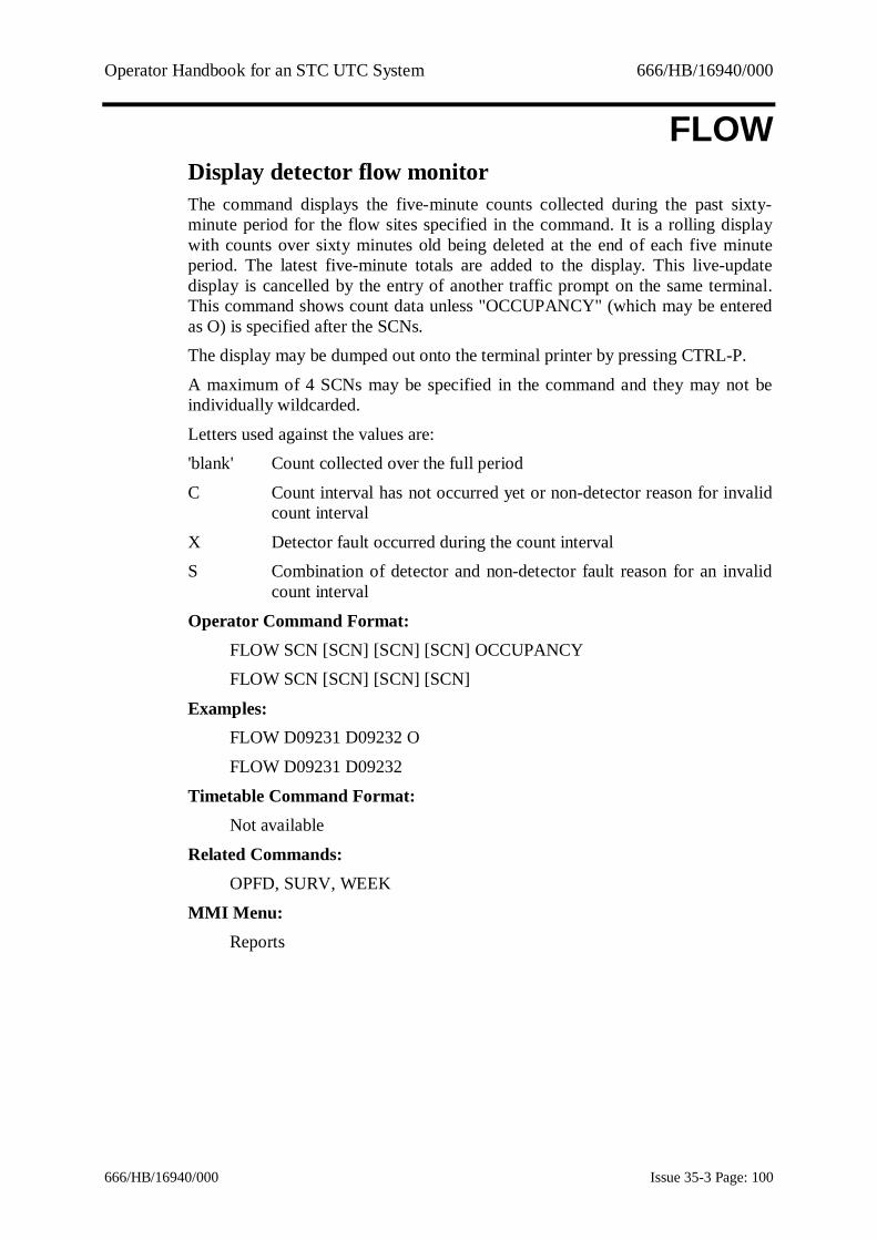
Operator Handbook for an STC UTC System 666/HB/16940/000
666/HB/16940/000 Issue 35-3 Page: 100
FLOWDisplay detector flow monitorThe command displays the five-minute counts collected during the past sixty-minute period for the flow sites specified in the command. It is a rolling displaywith counts over sixty minutes old being deleted at the end of each five minuteperiod. The latest five-minute totals are added to the display. This live-updatedisplay is cancelled by the entry of another traffic prompt on the same terminal.This command shows count data unless "OCCUPANCY" (which may be enteredas O) is specified after the SCNs.The display may be dumped out onto the terminal printer by pressing CTRL-P.
A maximum of 4 SCNs may be specified in the command and they may not beindividually wildcarded.
Letters used against the values are:'blank' Count collected over the full period
C Count interval has not occurred yet or non-detector reason for invalidcount interval
X Detector fault occurred during the count intervalS Combination of detector and non-detector fault reason for an invalid
count interval
Operator Command Format:FLOW SCN [SCN] [SCN] [SCN] OCCUPANCYFLOW SCN [SCN] [SCN] [SCN]
Examples:FLOW D09231 D09232 O
FLOW D09231 D09232
Timetable Command Format:Not available
Related Commands:OPFD, SURV, WEEK
MMI Menu:Reports

Operator Handbook for an STC UTC System 666/HB/16940/000
666/HB/16940/000 Issue 35-3 Page: 101
FLTASpecify which Faults raise a System AlarmThis command allows an operator to specify which faults should raise a systemalarm. A Fault category (which may be wild carded) and, optionally, anequipment type should be specified. The equipment type should be specified byentering an appropriate globally wildcarded SCN. If no equipment type isspecified, the command will operate on all equipment types.
Operator Command Format:FLTA [SCN] FAULT_CATEGORY
Example:FLTA J00000 100FLTA 700
Timetable Command Format:TIME FLTA [SCN] FAULT_CATEGORY
Example:07:00 FLTA J00000 120
Inverse Command:XFTA
MMI Menu:Faults

Operator Handbook for an STC UTC System 666/HB/16940/000
666/HB/16940/000 Issue 35-3 Page: 102
FLTGCreate Fault GroupThis ESS licensable command creates or modifies a fault category group whichmay be used to list and clear faults. A fuller description may be found in Section 8
The fault category group is assigned to a group number. The group number mustconsist of 4 digits, each in the range 1 to 9.
Operator Command Format:FLTG GROUPNO [“NAME”] [0] [+|-FLTCAT] …
Examples:FLTG 1111 +100 +200FLTG 1112 +100 +200 –121 -122
Timetable Command Format:Not available
Related Commands:LFLG, XFLG, XFLT
MMI Menu:Admin/Fault groups

Operator Handbook for an STC UTC System 666/HB/16940/000
666/HB/16940/000 Issue 35-3 Page: 103
FLTYSet fault manuallyThis command allows a particular category of fault to be set on a specified SCN.It may subsequently be overridden by the System that has priority. WildcardedSCNs are allowed, but fault category groups (e.g. 100, 220, ...), representing arange of faults, are not permitted. Fault categories are detailed in Appendix C.Terminals and the computer cannot be set as faulty.
Operator Command Format:FLTY SCN VALUE (VALUE = fault category)
Example:FLTY J11191 121
Timetable Command Format:Not available
Related Commands:XFLT, LSTF
MMI Menu:Faults

Operator Handbook for an STC UTC System 666/HB/16940/000
666/HB/16940/000 Issue 35-3 Page: 104
GDDDGraphical Detector Data DisplayThis command opens a window to create, modify, delete and display count datahistograms. The display shows a bar graph of occupancy, flow or sensor data forthe preceding 24 hours. The graph is updated at regular intervals which is initiallyfixed when the display is created.
Note: This command is only available on an MMI display.
Operator Command Format:GDDD
Example:GDDD
Timetable Command Format:Not available
Related Commands:FLOW, WEEK
MMI Menu:Reports
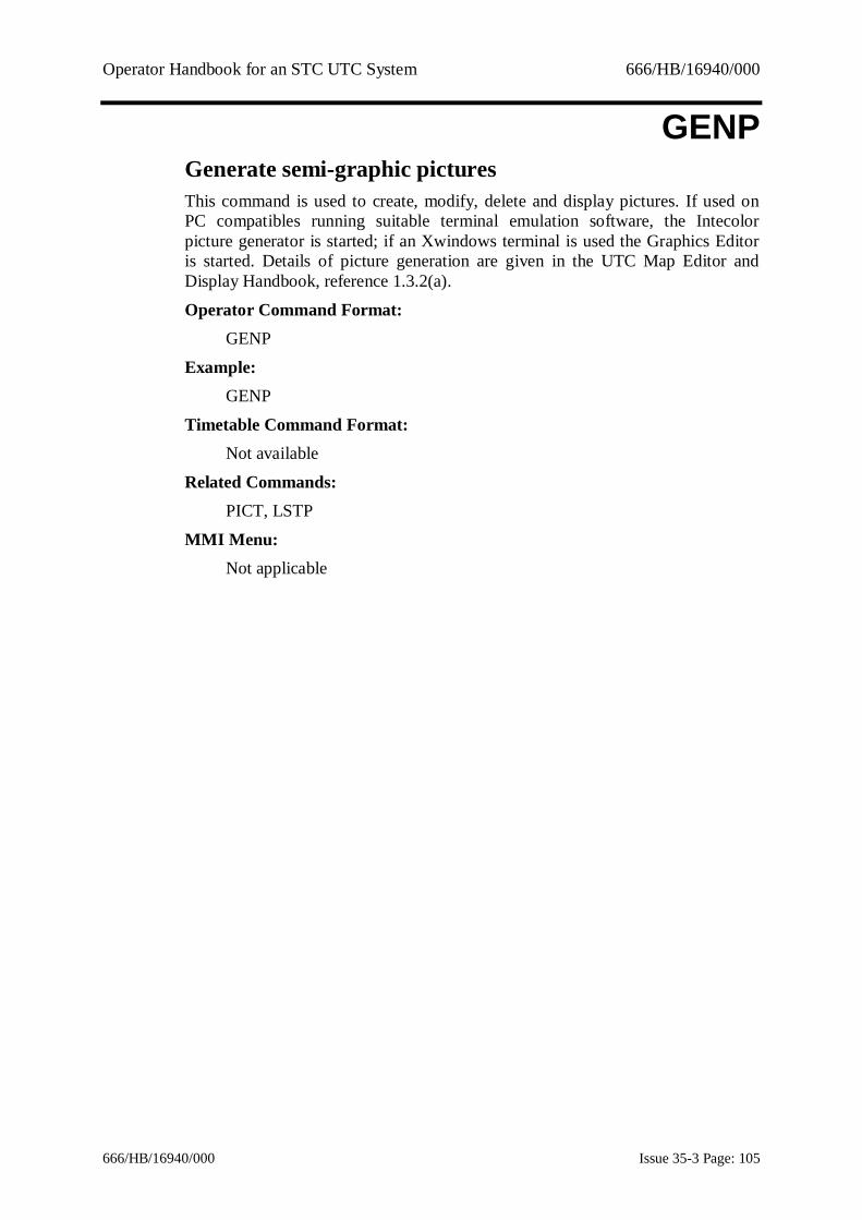
Operator Handbook for an STC UTC System 666/HB/16940/000
666/HB/16940/000 Issue 35-3 Page: 105
GENPGenerate semi-graphic picturesThis command is used to create, modify, delete and display pictures. If used onPC compatibles running suitable terminal emulation software, the Intecolorpicture generator is started; if an Xwindows terminal is used the Graphics Editoris started. Details of picture generation are given in the UTC Map Editor andDisplay Handbook, reference 1.3.2(a).
Operator Command Format:GENP
Example:GENP
Timetable Command Format:Not available
Related Commands:PICT, LSTP
MMI Menu:Not applicable

Operator Handbook for an STC UTC System 666/HB/16940/000
666/HB/16940/000 Issue 35-3 Page: 106
GUBARestore the Recorded User Baseline DataThis is a configurable command and may not be available on your system.Optional parameters may be attached to the GUBA command of either a SCOOTparameter (JNYT, STOC etc) and/or a SCOOT SCN. In this case the user baselineis only loaded for the selected SCOOT parameter and/or only the selected SCOOTSCN.
Operator Command format:GUBA [PARAM] [ScSCN]
Example:GUBA STOC N02112A
Related commands:LUBA, RUBA, DUBA, CHAN, VALU
Timetable Command Format:Not available
MMI Menu:SCOOT / Parameters

Operator Handbook for an STC UTC System 666/HB/16940/000
666/HB/16940/000 Issue 35-3 Page: 107
GWAVStart operator green waveThis command starts an operator green wave using the SCN specified. The SCNmay not be wildcarded.
If VIP routes are enabled by configuration the 'option' parameter can be anoverride value of a VIP convoy length. Also if a 'primed' green wave is enabledby configuration the 'option' parameter can be the text “PRIME”, or anabbreviation, to start a primed green wave.
The start and finish of a green wave is normally recorded in the log and output toterminals. If this is not required the description of the green wave, entered inDBAS should start with a ! character.
Operator Command Format:GWAV SCN [OPTION](OPTION = VIP convoy length or “PRIME”)
Example:GWAV G05119
Timetable Command Format:Not available
Inverse Command:XGWA
Related Commands:LSTG
MMI Menu:Traffic - Specials

Operator Handbook for an STC UTC System 666/HB/16940/000
666/HB/16940/000 Issue 35-3 Page: 108
HELPOnline HELP facilityThis command with no parameters displays a summary list of all operatorcommands and System features for which HELP is available. To obtain help on aparticular command or feature, type the HELP command with a command orfeature name as a parameter.
Operator Command Format:HELP [NAME] NAME = command or feature name
Examples:HELP
HELP GULP
Timetable Command Format:Not available
MMI Menu:HELP on menu bar

Operator Handbook for an STC UTC System 666/HB/16940/000
666/HB/16940/000 Issue 35-3 Page: 109
HRYCStart Manual Hurry CallThis command requests a controller to call the specified stage for the durationgiven by the value of ‘TIMER’. If the stage is demand dependent the appropriateD bit is automatically set. The facility is implemented as a single equipmentmanual wave (MWAV). Manual wave control started and finished messages willbe output to operator terminals at the start and end of the call. In addition, wherethe controller status is shown (e.g. DIPM or LSTS) it will appear as manual wavecontrol.A maximum of 5 equipments may be specified in a single command. the SCNmust be that of a junction or pelican controller, not wildcarded. STAGE must be acontroller stage (A-H or V) or X. If X is specified then any existing manual waveon the specified controller will be cancelled. If the stage is not specified for apelican controller the default is V.TIMER is the required duration of force in therange 60 to 300 seconds; if this is not specified the default value is 60 seconds
Operator Command Format:HRYC SCN STAGE [TIMER] [SCN STAGE [TIMER]] [SCN STAGE[TIMER]] [SCN STAGE [TIMER]] [SCN STAGE [TIMER]]
Example :HRYC J03111 A 90
HRYC J03112 B 90 J03211 D 150HRYC J03211 X J03212 C 70
HRYC P05111 90
Timetable Command Format :not available
Related commands :XHRY, MWAV
MMI Menu :Traffic - Specials

Operator Handbook for an STC UTC System 666/HB/16940/000
666/HB/16940/000 Issue 35-3 Page: 110
ICASInsert an entry into a CASTThis allows you to add commands into a particular CAST. A CAST number oridentifier (the first word of the CAST title) must be specified, along with thecommand to the inserted with its parameters. If the entry number quoted in thecommand already exists the new command is added after that entry. If the entrynumber quoted is greater than the highest existing entry or this parameter isomitted the command is inserted as the last entry in the CAST.
A CAST index may also be specified. If omitted, the command entry is inserted atthe end of the CAST. If an index is supplied, the command entry is inserted at theposition immediately following the command with that index. If a CAST index of0 is specified the command is inserted at the beginning of the CAST.
Operator Command Format:ICAS CAST_number [INDEX] Command [Parameters]
or ICAS CAST_mnemonic [INDEX] Command [Parameters]
Examples:ICAS 1 5 CLOS C01356ICAS peak 21 OPEN C01356
Timetable Command Format:Not available
Inverse Command:DCAS
Related Commands:LCAS, ACAS, NCAS, ECAS
MMI Menu:Admin/SCOOT/Traffic

Operator Handbook for an STC UTC System 666/HB/16940/000
666/HB/16940/000 Issue 35-3 Page: 111
IFLTInhibit Fault by CategoryThis facility allows the user to set the UTC System so that it will ignore certaincategories of faults on specified equipments.
When a fault is inhibited, that fault will no longer be reported on operatorterminals, in the system log or in LSTF. If the fault is raised when it is inhibitedthe fault is implicitly cleared.Inhibiting a fault, inhibits the raising and consequential effects of a fault, not justthe reporting of the fault. For example, normally a manual control reply bit willisolate a junction. If the manual control fault is inhibited, the junction will be lefton normal control when the MC bit is present. If the junction really is undermanual control other faults such as plan compliance faults are likely to be raised.In other words, as with IHRW these commands should be used with care.Not all fault categories can be inhibited. A list of those fault categories which maybe inhibited is shown at Appendix C – Fault and Advice Details.This is a licenced feature.
Operator Command Format:IFLT SCN [Fault_Category]
Examples:IFLT J01123 121
IFLT J00000 132
Timetable Command Format:09:31 IFLT J00000 132
Inverse Command:XIFT
Related Command:LIFT
MMI Menu:Faults

Operator Handbook for an STC UTC System 666/HB/16940/000
666/HB/16940/000 Issue 35-3 Page: 112
IHPCInhibit Plan Compliance fault isolationThis command suspends the isolation of an intersection or pelican controller whena plan compliance fault is reported. The command may be actioned on a singleinjunction or Pelican SCN or on a sub-area or wildcarded sub-area.For intersections, plan compliance fault 121 or wrong stage returned fault 122may be selected. For pelicans, only plan compliance fault 121 is available. Thewildcard 120 may be used with junction or sub-area SCNs but not pelican SCNs.
This command may be cancelled automatically using the command cancelfacility. See Section 9.1.6 for details.
Operator Command Format:IHPC SCN Fault_Number [TIME]
Examples:IHPC J01123 121IHPC P01321 120
IHPC P01321 120 12:00
Timetable Command Format:TIME IHPC SCN Fault_Number
Example:15:55 IHPC J01123 121
Inverse Command:XIHP
MMI Menu:Faults

Operator Handbook for an STC UTC System 666/HB/16940/000
666/HB/16940/000 Issue 35-3 Page: 113
IHRWInhibit reply word analysisThis command allows you to inhibit the reply word analysis from any equipmentor remote request connected to the System. The SCN of the equipment may not bewildcarded. The inhibition may be cancelled using the XIHR command.This command may be cancelled automatically using the command cancelfacility. See Section 9.1.6 for details. The optional time parameter can only beused in conjunction with the, configurable, command cancel facility.
If the STANDARD parameter is used, controllers which are connected to an OTUwhich becomes faulty will become “isolated by OTU fault” and will appear in thelisting produced by an LSTS 6 command. This is the default behaviour if theSTANDARD|ENHANCED parameter is omitted.
If the ENHANCED parameter is used, controllers which are connected to an OTUwhich becomes faulty will not become “isolated by OTU fault” and will notappear in the listing produced by an LSTS 6 command.If a controller has reply word analysis inhibited this fact will be reported in theFault Messages part of a DIPM display.
Operator Command Format:IHRW SCN|REMOTE REQUEST [STANDARD|ENHANCED] [TIME]
Examples:IHRW J01123IHRW P01321
IHRW J03111 STANDARDIHRW P03112 ENHANCED
IHRW P01321 12:00
Timetable Command Format:TIME IHRW SCN [STANDARD|ENHANCED]
Inverse Command:XIHR
Related Commands:LIHR
MMI Menu:Faults
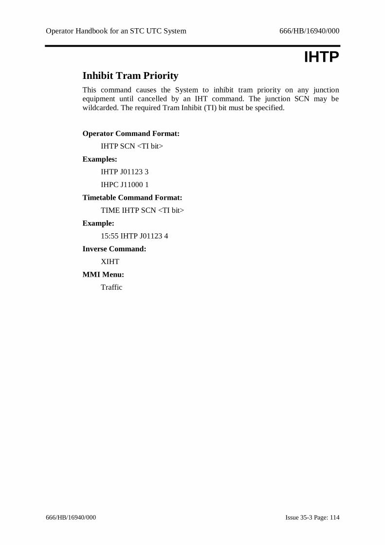
Operator Handbook for an STC UTC System 666/HB/16940/000
666/HB/16940/000 Issue 35-3 Page: 114
IHTPInhibit Tram PriorityThis command causes the System to inhibit tram priority on any junctionequipment until cancelled by an IHT command. The junction SCN may bewildcarded. The required Tram Inhibit (TI) bit must be specified.
Operator Command Format:IHTP SCN <TI bit>
Examples:IHTP J01123 3
IHPC J11000 1
Timetable Command Format:TIME IHTP SCN <TI bit>
Example:15:55 IHTP J01123 4
Inverse Command:XIHT
MMI Menu:Traffic
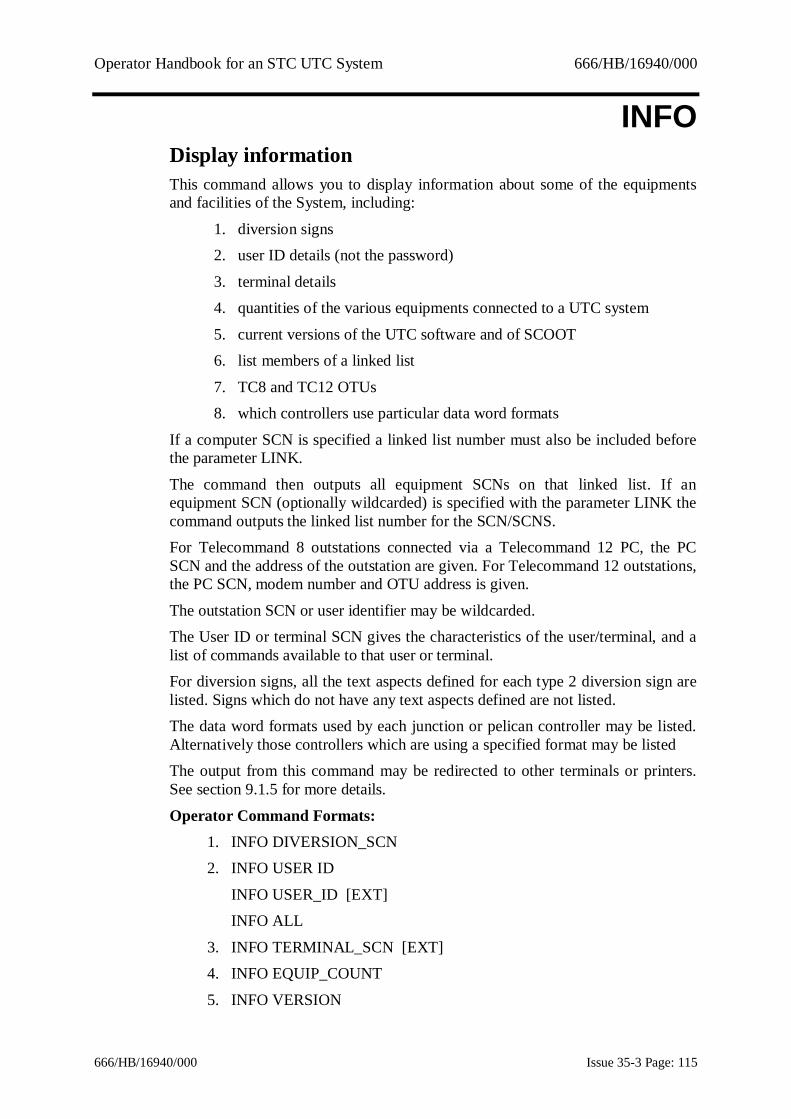
Operator Handbook for an STC UTC System 666/HB/16940/000
666/HB/16940/000 Issue 35-3 Page: 115
INFODisplay informationThis command allows you to display information about some of the equipmentsand facilities of the System, including:
1. diversion signs2. user ID details (not the password)
3. terminal details4. quantities of the various equipments connected to a UTC system
5. current versions of the UTC software and of SCOOT6. list members of a linked list
7. TC8 and TC12 OTUs8. which controllers use particular data word formats
If a computer SCN is specified a linked list number must also be included beforethe parameter LINK.
The command then outputs all equipment SCNs on that linked list. If anequipment SCN (optionally wildcarded) is specified with the parameter LINK thecommand outputs the linked list number for the SCN/SCNS.For Telecommand 8 outstations connected via a Telecommand 12 PC, the PCSCN and the address of the outstation are given. For Telecommand 12 outstations,the PC SCN, modem number and OTU address is given.
The outstation SCN or user identifier may be wildcarded.The User ID or terminal SCN gives the characteristics of the user/terminal, and alist of commands available to that user or terminal.For diversion signs, all the text aspects defined for each type 2 diversion sign arelisted. Signs which do not have any text aspects defined are not listed.The data word formats used by each junction or pelican controller may be listed.Alternatively those controllers which are using a specified format may be listedThe output from this command may be redirected to other terminals or printers.See section 9.1.5 for more details.
Operator Command Formats:1. INFO DIVERSION_SCN2. INFO USER ID
INFO USER_ID [EXT]INFO ALL
3. INFO TERMINAL_SCN [EXT]4. INFO EQUIP_COUNT
5. INFO VERSION

Operator Handbook for an STC UTC System 666/HB/16940/000
666/HB/16940/000 Issue 35-3 Page: 116
6. INFO SCN [LINK]
INFO SCN LINKED_LIST [LINK]7. INFO OUTSTATION_SCN
8. INFO SCN FORMAT [FORMAT NO]
Examples:1. INFO V771112. INFO WENDY
INFO WENDY EXT INFO ALL
3. INFO T01003 INFO T01099 EXT
4. INFO EQUIP_COUNT5. INFO VERSION
6. INFO J11121 LINK INFO H00000 1 LINK
INFO J00000 LINK7. INFO X23110
INFO X000008 INFO J00000 FORMAT
INFO P00000 FORMAT 9
Timetable Command Format:Not available
MMI Menu:Info
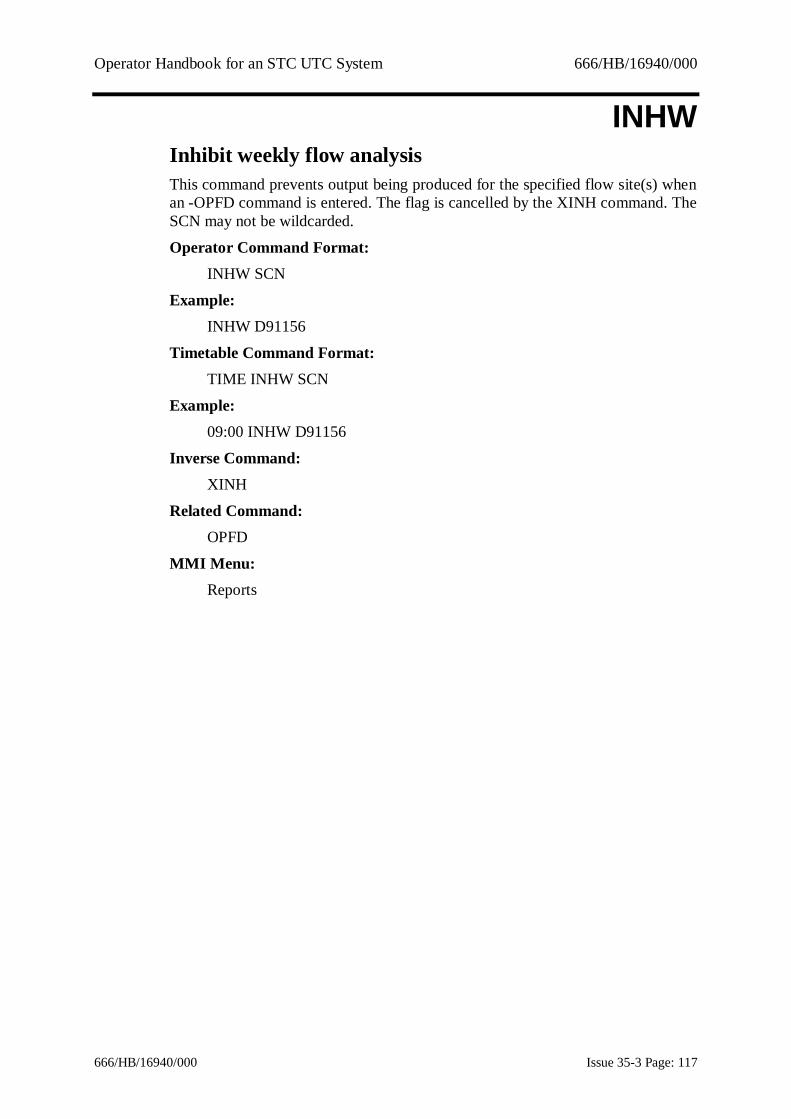
Operator Handbook for an STC UTC System 666/HB/16940/000
666/HB/16940/000 Issue 35-3 Page: 117
INHWInhibit weekly flow analysisThis command prevents output being produced for the specified flow site(s) whenan -OPFD command is entered. The flag is cancelled by the XINH command. TheSCN may not be wildcarded.
Operator Command Format:INHW SCN
Example:INHW D91156
Timetable Command Format:TIME INHW SCN
Example:09:00 INHW D91156
Inverse Command:XINH
Related Command:OPFD
MMI Menu:Reports

Operator Handbook for an STC UTC System 666/HB/16940/000
666/HB/16940/000 Issue 35-3 Page: 118
INTDIntroduce diversionThis command is used to introduce a selected diversion. Wildcards are notallowed.
This command may be cancelled automatically using the command cancelfacility. See Section 9.1.6 for details.
Operator Command Format:INTD SCN [TIME}
Example:INTD U09231INTD U09231 12:00
Timetable Command Format:TIME INTD SCN
Example:16:30 INTD U09231
Inverse Command:REMD
MMI Menu:Traffic - Special

Operator Handbook for an STC UTC System 666/HB/16940/000
666/HB/16940/000 Issue 35-3 Page: 119
ISOLIsolate controllerThis command isolates the specified controller. The controller remains isolateduntil the command is cancelled by XISO. The SCN may be wildcarded if desired.
An isolated controller is normally listed as a fault although the systemconfiguration can be set by STC not to show isolated controllers in the outputfrom LSTF. The system still associates a fault category with an isolated controller.This command may be cancelled automatically using the command cancelfacility. See Section 9.1.6 for details.
Operator Command Format:ISOL SCN [TIME}
Example:ISOL J09231
ISOL J09231 12:00
Timetable Command Format:TIME ISOL SCN
Example:16:30 ISOL J09231
Inverse Command:XISO
Related Commands:DISO, XDIS
MMI Menu:Faults

Operator Handbook for an STC UTC System 666/HB/16940/000
666/HB/16940/000 Issue 35-3 Page: 120
KILLShutdown SystemOn an Alpha based UTC system this command causes the Traffic System and thecomputer on which it is running to shut down. Any street equipment connected tothe computer is isolated and any open disk files are closed.On a PC SCOOT system this command causes the Traffic System to shut downAny street equipment connected to the computer is isolated and any open diskfiles are closed. . If necessary, the computer may be shut down separately.
As the Traffic System is halted the Hardware SCN must also be entered to preventaccidental use.
Operator Command Format:KILL Hardware_SCN
Example:KILL H01000
Timetable Command Format:Not available
MMI Menu:Manager

Operator Handbook for an STC UTC System 666/HB/16940/000
666/HB/16940/000 Issue 35-3 Page: 121
LACCList CAST AssociationsThis command lists the associations of CASTs with changes in SCOOT regioncycle time made by the ACCT command.
Changes in which the cycle time rises or falls to the given value are distinct.A '+' in the listing indicates that the CAST is called when the cycle time rises tothe given value and a '-' when the cycle time falls to the given value.
Operator Command Format:LACC [SCOOT_Region_SCN]
Example:LACC RCA
Timetable Command Format:Not available
Related commands:ACCT, XACC
MMI Menu:Traffic / Specials
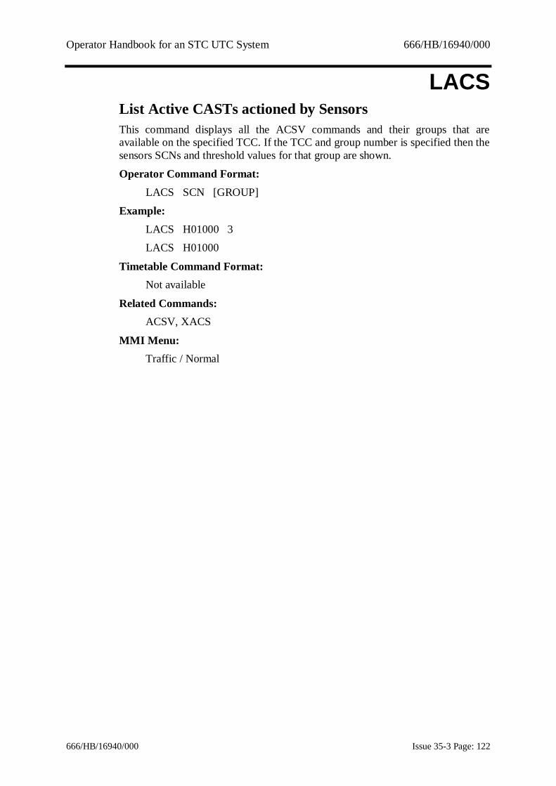
Operator Handbook for an STC UTC System 666/HB/16940/000
666/HB/16940/000 Issue 35-3 Page: 122
LACSList Active CASTs actioned by SensorsThis command displays all the ACSV commands and their groups that areavailable on the specified TCC. If the TCC and group number is specified then thesensors SCNs and threshold values for that group are shown.
Operator Command Format:LACS SCN [GROUP]
Example:LACS H01000 3LACS H01000
Timetable Command Format:Not available
Related Commands:ACSV, XACS
MMI Menu:Traffic / Normal
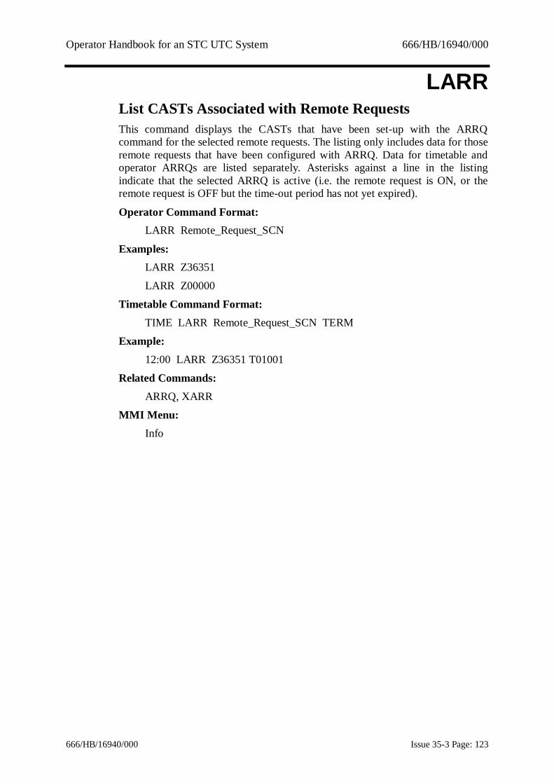
Operator Handbook for an STC UTC System 666/HB/16940/000
666/HB/16940/000 Issue 35-3 Page: 123
LARRList CASTs Associated with Remote RequestsThis command displays the CASTs that have been set-up with the ARRQcommand for the selected remote requests. The listing only includes data for thoseremote requests that have been configured with ARRQ. Data for timetable andoperator ARRQs are listed separately. Asterisks against a line in the listingindicate that the selected ARRQ is active (i.e. the remote request is ON, or theremote request is OFF but the time-out period has not yet expired).
Operator Command Format:LARR Remote_Request_SCN
Examples:LARR Z36351
LARR Z00000
Timetable Command Format:TIME LARR Remote_Request_SCN TERM
Example:12:00 LARR Z36351 T01001
Related Commands:ARRQ, XARR
MMI Menu:Info
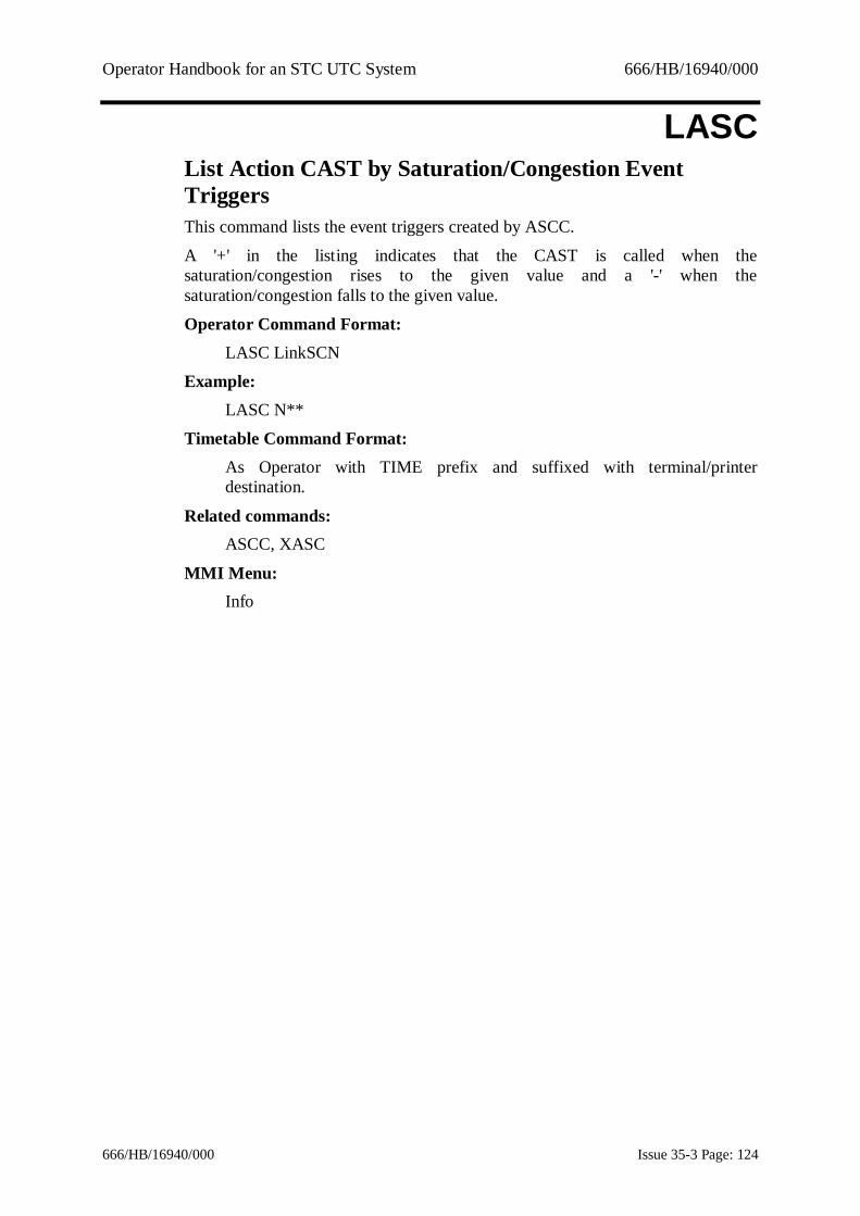
Operator Handbook for an STC UTC System 666/HB/16940/000
666/HB/16940/000 Issue 35-3 Page: 124
LASCList Action CAST by Saturation/Congestion EventTriggersThis command lists the event triggers created by ASCC.
A '+' in the listing indicates that the CAST is called when thesaturation/congestion rises to the given value and a '-' when thesaturation/congestion falls to the given value.
Operator Command Format:LASC LinkSCN
Example:LASC N**
Timetable Command Format:As Operator with TIME prefix and suffixed with terminal/printerdestination.
Related commands:ASCC, XASC
MMI Menu:Info

Operator Handbook for an STC UTC System 666/HB/16940/000
666/HB/16940/000 Issue 35-3 Page: 125
LCASList the contents of a CASTThis command allows you to view all the commands contained within a particularCAST either at a terminal or on a printer.
The number preceding the description of each command is the CAST index and isneeded by the ICAS and DCAS commands to specify a position within a CAST.If the number is 0, then all available CASTs and their names are listed. If theCAST is empty then an asterisk (*) is shown in place of the name. The commandLCAS 0 lists the numbers and names of all non-empty CASTs.An optional wildcarded SCN may be specified, in which case the display will belimited to only those entries concerning that SCN. LCAS supports the use ofparent/child wildcarded SCOOT SCNs.
The output from this command may be redirected to other terminals or printers.See section 9.1.5 for more details.
Operator Command Format:LCAS CAST_number | CAST_mnemonic [SCN] [E[XPAND]]
Examples:LCAS 1
LCAS peakLCAS 0 - list numbers and names of non-empty CASTs
LCAS 0 EXP - list numbers and names of non-empty CASTswith their contents (and named empty CASTs).
LCAS 0 J01111 EXP - list entries for J01111 in all CASTs.
Timetable Command Format:Not available
Inverse Command:None but listings may be terminated by <CTRL> O (non-MMI)
Related Commands:ICAS, ACAS, NCAS, DCAS, ECAS
MMI Menu:Info/Admin/Traffic/SCOOT

Operator Handbook for an STC UTC System 666/HB/16940/000
666/HB/16940/000 Issue 35-3 Page: 126
LCOFList car park occupancy filesThis command allows you to view a list of the configured car park occupancyfiles or the details of just one file if its number is specified. The output lists thefile number, the date of the data and a description.
Operator Command Format:LCOF [nn]
Examples:LCOFLCOF 4
Timetable Command Format:Not available
Inverse Command:None but listings may be terminated by <CTRL> O (non-MMI)
Related Commands:DCOF, RCOF, UCOF
MMI Menu:Car Parks, Special Data

Operator Handbook for an STC UTC System 666/HB/16940/000
666/HB/16940/000 Issue 35-3 Page: 127
LEMEList equipment messagesThis command allows the user to list equipment messages created by EMES.The LEME command with no parameters will list every EMES message.
The SCN may be wildcarded (unlike for EMES). It may be omitted, which meansall SCNs.
The optional fault category is used to distinguish between messages; if zero oromitted, all fault categories will be displayed. Any positive number will beaccepted, but also a genuine fault category or wildcarded fault category.The optional message string can be used to search for that substring in the existingEMES messages.
Operator Command Format:LEME [SCN] [FAULT_CATEGORY] [STRING]
Examples:LEME (list all EMES messages)LEME J01000 (list messages for junctions in subarea 01)
LEME 777 (list messages with number 777)LEME "compliance" (list messages containing string "compliance")
Timetable Command Format:As Operator with TIME prefix and suffixed with terminal/printerdestination.
Related Commands:EMES, XEME
MMI Menu:Faults

Operator Handbook for an STC UTC System 666/HB/16940/000
666/HB/16940/000 Issue 35-3 Page: 128
LFLGList fault category groupsThis, optional, command allows you to view all the fault category groups whichhave been set up.
Operator Command Format:LFLG
Examples:LFLG
Timetable Command Format:Not available
Related Commands:FLTG, XFLG, XFLT
MMI Menu:Admin/Fault groups

Operator Handbook for an STC UTC System 666/HB/16940/000
666/HB/16940/000 Issue 35-3 Page: 129
LFTAList Faults which raise System AlarmsThis command displaysthose faults which will raise the system alarm indicatorwhyen the fault occurs. With no parameter the complete list of faults will bedisplayed. A fault category, fault group or equipment type may be specified
Operator Command Format:LFTA [SCN] [FAULT_CATEGORY]
Examples:LFTA J00000LFTA
Timetable Command Format:TIME LFTA [SCN] [FAULT_CATEGORY]
Examples:06:30 LFTA J00000
07:00 LFTA
Inverse Command:None
Related Commands:FLTA, XFTA
MMI Menu:Faults

Operator Handbook for an STC UTC System 666/HB/16940/000
666/HB/16940/000 Issue 35-3 Page: 130
LIFTList Inhibited FaultsThis facility allows the user to see which faults have been inhibited by use of theIFLT command.
Not all fault categories can be inhibited. A list of those fault categories which maybe inhibited is shown at Appendix C – Fault and Advice Details.
This is a licenced feature.
Operator Command Format:LIFT [SCN] [Fault_Category]
Examples:LIFTLIFT J01123
LIFT J00000 132
Timetable Command Format:09:33 LIFT >T01002
Related Commands:IFLT, XIFT
MMI Menu:Reports

Operator Handbook for an STC UTC System 666/HB/16940/000
666/HB/16940/000 Issue 35-3 Page: 131
LIHRList equipments with reply word analysis inhibitedThis command lists those equipments which have reply word analysis inhibited.The SCN may be wildcarded. It should be noted that a command of the formIHRW X12340 inhibits reply word analysis for all equipments on that OTU.However, a command of the form LIHR Xnnnn0 is not allowed since it is theequipments on the OTU which are affected not the OTU itself.
Operator Command Format:LIHR SCN
Examples:LIHR A00000
LIHR P00000LIHR J12000
Timetable Command Format:TIME LIHR SCN TERM
Example:08:00 LIHR A00000 T01001
Related Commands:IHRW, XIHR
MMI Menu:Reports

Operator Handbook for an STC UTC System 666/HB/16940/000
666/HB/16940/000 Issue 35-3 Page: 132
LIHSList Equipment HistoryThis command is a variation on the LOGO command. The command is intendedto be able to answer the question - what was a particular site doing at a particulardate and time? Normally when using LOGO to locate this kind of information it isnecessary to scan several hours of output working out which messages arerelevant for the time you are interested in. Specifically it may be difficult to workout which mode of control was in effect and what faults were present at the timein question.LIHS does this for you automatically. You specify a site, a date and time. It onlyincludes messages from the log which are either fault raised or cleared messagesor are mode change messages (such as 'Timetable plan started', 'SCOOT controlfinished', &c). It then filters out any message which it can work out has beensuperceded by a later message. For instance, given the message sequence.
SCOOT control finished on R* SCOOT control started on N01234
Timetable plan 4 started on A01000 Timetable plan 5 started on A01200
Then LIHS J01234 would reduce this down to : SCOOT control started on N01234
Timetable plan 5 started on A01200Enter a date range to specify the system logs that should be scanned to retrieve thestatus. The time entered should be the time on the end day of the date range forwhich you want the historic status displayed.
Operator Command Format:LIHS [SCN] [FAULT.CAT] [DATE] [TIME]
Examples:LIHS J01231 10-JAN-2001:14-JAN-2001 17:37
Timetable Command Format:TIME LIHS [SCN] [FAULT.CAT] [DATE] [TIME] TERMINAL
Example:09:33 LIHS J10231 >T01002
Related Commands:LOGO
MMI Menu:Not available

Operator Handbook for an STC UTC System 666/HB/16940/000
666/HB/16940/000 Issue 35-3 Page: 133
LIPTList plan timingsThis command lists the stored plan timings for the specified SCN. Local plans areomitted by default. To see both local and non-local plans the parameter LOCALshould be added to the command. The SCN may be wildcarded or omitted if aplan number is given. If the plan number specified is zero, the current timings forthe SCN are listed including any vary or offset changes. If no plan number isgiven, the SCN may not be wildcarded or omitted. This form of the commandcauses all fixed-time plans for that SCN to be listed.The option LOCAL is used to display local plans as well as the other plans. Iflocal is not entered then local plans are not displayed.The option DESCRIPTION appends the plan name to the plan timings.
One of the optional parameters must be specified. A LIPT command with noparameters is illegal.
The output from this command may be redirected to other terminals or printers.See section 9.1.5 for more details.
Operator Command Format:LIPT [SCN [FIXEDTIME | SCOOT | GREENWAVE] [PLAN] [LOCAL |ERRORS | HISTORY | TIMINGS | DESCRIPTION]]
Note: If the currently implemented plan is requested for equipment operatingunder SCOOT control then the plan line output only reflects accuratelythe stage sequence and any fixed offsets and stage durations. The stageoffsets for stages under SCOOT control are shown as being offset by 127seconds, the current timings implemented are not shown. If thisinformation is required use the PLAN parameter of the VALU command.
Examples:LIPT A01000 FIXEDTIME 4LIPT 22 ERRORS
LIPT J11191 SCOOT 1 HISTORYLIPT J00000 F 1 LOCAL
Timetable Command Format:Not available
Inverse Command:None but listings may be terminated by <CTRL> O (non-MMI)
MMI Menu:Info
Operator Handbook for an STC UTC System 666/HB/16940/000
666/HB/16940/000 Issue 35-3 Page: 134
LIVEStop simulation of an equipmentNOTE: This is an unsupported feature for use by STC maintenance engineers.This command stops simulation of the specified equipment. The valid equipmenttypes are outstations, junctions, pelicans, special facilities, count detectors, queuedetectors, SCOOT detectors, car parks, car park signs and diversion signs. If acomputer SCN is entered then an outstation address must be specified. If theequipment is an outstation or outstation address then simulation is stopped for allequipment on the outstation. The SCN may be wildcarded except for computerSCNs.
Operator Command Format:LIVE COMPUTER_SCN ADDRESS
LIVE SCN
Examples:LIVE J11241LIVE X00000
LIVE H01000 12
Timetable Command Format:Not available
Inverse Command:XLIV
Related Command:None.
MMI Menu:Not applicable

Operator Handbook for an STC UTC System 666/HB/16940/000
666/HB/16940/000 Issue 35-3 Page: 135
LJNLList command journalThis command allows you to list the commands in the operator journal for thespecified computer. Optional start and end times may be specified with thiscommand. If no computer is specified then the contents of the journals for all thecomputers in the System are listed.
If an optionally wildcarded UTC or SCOOT SCN is specified then the list isrestricted to those equipments matched by that SCN. If a computer SCN is enteredthen only the journal on the specified computer will be listed. LJNL supports theuse of parent/child wildcarded SCOOT SCNs.
The output from this command may be redirected to other terminals or printers.See section 9.1.5 for more details.
Operator Command Format:LJNL [SCN] [TIME1-[TIME2]]
Examples:LJNL H01000
LJNL 16:45LJNL 16:45-18:20
Timetable Command Format:Not available
Related Commands:CJNL
Inverse Command:None but listings may be terminated by <CTRL> O (non-MMI)
MMI Menu:Info/Reports

Operator Handbook for an STC UTC System 666/HB/16940/000
666/HB/16940/000 Issue 35-3 Page: 136
LLCFList link conversion factorsThis command lists the conversion factor between LPUs and vehicle counts for aparticular link. The conversion factor is given as a number and fraction (innumber of vehicles/LPU).When used with the Link SCN and Terminal parameters, as in example 1, thiscommand lists the conversion factors for specified links on the specified terminal.When used with only the Link SCN parameters, as in example 2, this commandlists the conversion factors for the specified links on the terminal on which thecommand was entered.
When used with the Counting Detector SCN and Terminal parameters, as inexample 3, this command lists the conversion factors for all links associated withthe specified counting detectors on the specified terminal. When used with onlythe Counting Detector SCN parameter, as in example 4, this command lists theconversion factors for all links associated with the specified counting detectors onthe terminal on which the command was entered. When used with no parameters,as in example 5, this command lists the conversion factors for all links on theterminal's default district on the terminal on which the command was entered.
Both the Link SCN and the Counting Detector SCN parameters may bewildcarded.
Calibration of SCOOT detectors for vehicle counting is described under the SSSUcommand.
The output from this command may be redirected to other terminals or printers.See section 9.1.5 for more details.
Operator Command Format:LLCF [count_detector_SCN | link_SCN]
Examples:LLCF N12345A >T01001LLCF N12345ALLCF D12345 >T01001LLCF D00000LLCF
Timetable Command Format:Not available
Related Commands:ASLD, SSSU
MMI Menu:Info

Operator Handbook for an STC UTC System 666/HB/16940/000
666/HB/16940/000 Issue 35-3 Page: 137
LLNKTransmit local link inhibit bitThis command causes the System to determine the local link inhibit control bitnumber for the specified controller(s) from the database and continuously transmitthat bit to the controller until cancelled. The SCN may be wildcarded.This command may be cancelled automatically using the command cancelfacility. See Section 9.1.6 for details.
Operator Command Format:LLNK SCN [TIME}
Example:LLNK J11191
LLNK J11191 12:00
Timetable Command Format:TIME LLNK SCN
Example:08:00 LLNK J11191
Inverse Command:XLLN
MMI Menu:Traffic - Normal

Operator Handbook for an STC UTC System 666/HB/16940/000
666/HB/16940/000 Issue 35-3 Page: 138
LMONLink Occupancy MonitorThis command sets up a live update display on the terminal for specified link. TheSCN specified in the command may not be wildcarded. Various SCOOTparameters are displayed for the line, and a horizontally scrolling area displays thedetector data stream for each link. The M08, M10, M11 and M14 event messagesused in Link Validation may be displayed. See reference 1.3.2(e) for more detail.In order to start, or stop, the 4 event messages the "1", "2", "3" and "4" keys areused. Pressing a key once starts the message, pressing it again stops it.The display may be dumped to the printer configured for the terminal by pressingCTRL-P.
Operator Command Format:LMON ScSCN
Example:LMON N11191A
Timetable Command Format:Not available
Related Commands:LVAL, NFTD, RFTD
MMI Menu:SCOOT
Operator Handbook for an STC UTC System 666/HB/16940/000
666/HB/16940/000 Issue 35-3 Page: 139
LNMCList network message commandsThis command displays command messages sent to remote computers on thenetwork by NMCS commands.
If a non-zero command number is specified, the message configured for thatNMCS command is output. If the command number is specified as zero all NMCScommand messages are output.
Operator Command Format:LNMC COMMAND_NO
Example:LNMC 125
Timetable Command Format:Not available
Related Command:NMCS
MMI Menu:Info

Operator Handbook for an STC UTC System 666/HB/16940/000
666/HB/16940/000 Issue 35-3 Page: 140
LOGMList Event Message LogThis command lists the contents of the stored event message log. An optionallywildcarded SCN may be specified, in which case the display shows the messagesconcerned with each SCN. An event message may also be specified in order tolimit the display further.
The command accepts a single date or date range of the forms:DATE
DATE1:DATE2DATE1:
DATE2 must be later than DATE1 and neither may be later than today.DATE1 and DATE2 both default to today if either is omitted
If no date or date interval is given, the current date is assumed. If no time intervalis specified, the whole of the day is assumed.
The word 'NOW' may be entered to mean the current time.
Operator Command Format:LOGM [SCN] [MESSAGE-NUMBER] [DATE] [TIME1-TIME2]
Example:LOGM RHUN** M14 16:00-18:00
Timetable Command Format:Not available
Related Commands:EDAV, LSTM
MMI Menu:Reports

Operator Handbook for an STC UTC System 666/HB/16940/000
666/HB/16940/000 Issue 35-3 Page: 141
LOGOList message logThis command lists the contents of the stored message log. The log may be listedfor a single day, a number of days between two dates and from a particular dateuntil today. In addition a time range may be specified so that only those entrieswhich fall inside the time range are listed for each day. The log may also beexamined for a specified SCN (wildcarded if required) and/or fault category.If no date is specified the current date is assumed. If no time interval is specifiedall data for the date(s) specified is output.The word 'NOW' may be entered, to mean the current time. If no date is givenafter the colon that divides the two dates, today's date is assumed. YESTERDAY(abbreviated to Y) may be used to list yesterday’s data. To list data for anyparticular day of the week the name of the day may be entered, e.g. MON forMonday, TUE for Tuesday, etc.
If the SCN is wildcarded, stored messages that are a sub-set of the wildcardedSCN are reported. If a specific non-wildcarded SCN is entered, then wildcardedcommands in the stored message log that refer to the input SCN, WILL NOT BEREPORTED.
The output from this command may be redirected to other terminals or printers.See section 9.1.5 for more details.
If the command is entered in the MMI command entry window, the outputappears in the Output Messages Window. If the command is entered in from theMMI pull down menu, the output appears in a System Log Output window.
Operator Command Format:LOGO [SCN | UIC] [OPTION] [VALUE] [SEARCH-STRING] [DATE | DATE: | DATE1:DATE2] [TIME1-TIME2]
UIC = User IDOPTION = RELATED list sites related to this SCN or HIDDEN to viewhidden messagesVALUE = fault category (see Appendix C but excluding the OPEcategories)SEARCH-STRING = displays message containing this text, enclosed in “”
Examples:LOGO X04140
LOGO 1-APR-87LOGO 1-APR-87:
LOGO 1-APR-87:1-JAN-88LOGO 08:00-08:40
LOGO J11191 08:00-NOW

Operator Handbook for an STC UTC System 666/HB/16940/000
666/HB/16940/000 Issue 35-3 Page: 142
LOGO A23000 100 1-APR-87 08:00-08:45
LOGO A23000 100 1-APR-87: 08:00-08:45LOGO A23000 100 1-APR-87:1-JAN-88 08:00-08:45
LOGO YLOGO MON:WED
Timetable Command Format:TIME LOGO [SCN] [VALUE] TERMINAL
Example:08:00:00 LOGO J11191 T01001
Inverse Command:None but listings may be terminated by <CTRL> O (non-MMI)
Related Commands:EDAV
MMI Menu:Faults, Reports

Operator Handbook for an STC UTC System 666/HB/16940/000
666/HB/16940/000 Issue 35-3 Page: 143
LOTULog OTU control and reply bitsThis command allows you to record the OTU control and reply information for upto four specified outstations simultaneously. All the data which is logged on anyone day will be stored in the same fileEach file is capable of storing from 1 to 24 hours of logging data, the exactmaximum value being set up during the Data Preparation process (DBAS), in theUTC SYSTEM WIDE VARIANTS form. An optional end time may be specifiedwith the command. If is wished to log an OTU continuously the word CONTshould be added to the end of the LOTU command
The contents of the log file may be examined using the DLOT command. The logfile is kept for the number of days specified in the database after which it isdeleted. Accumulation of log data may be stopped using the XLOT command.
Operator Command Format:- Common format for all systems
LOTU SCN [END_TIME] [CONT]
- Telecommand 8 SystemLOTU COMPUTER_SCN ADDRESS [END_TIME] [CONT]
- Telecommand 8 OTUs on a Telecommand 12 PCLOTU PC_SCN ADDRESS [END_TIME] [CONT]
- Telecommand 12 OTUsLOTU PC_SCN TC12_MODEM ADDRESS [END_TIME] [CONT]
Examples:LOTU X01450
LOTU X01450 18:00LOTU X01460 CONT
LOTU H01000 145LOTU H01000 145 18:00
LOTU E01001 5 16 15:00
Timetable Command Format:- Common format for all systems
TIME LOTU SCN [END_TIME]
- Telecommand 8 SystemTIME LOTU COMPUTER_SCN ADDRESS [END_TIME]
- Telecommand 8 OTUs on a Telecommand 12 PCTIME LOTU PC_SCN ADDRESS [END_TIME]

Operator Handbook for an STC UTC System 666/HB/16940/000
666/HB/16940/000 Issue 35-3 Page: 144
- Telecommand 12 OTUs
TIME LOTU PC_SCN TC12_MODEM ADDRESS [END_TIME]
Examples:TIME LOTU X01450TIME LOTU X01450 18:00
TIME LOTU H01000 145TIME LOTU H01000 145 18:00
TIME LOTU E01001 5 16 15:00
Inverse Command:XLOT
Related Commands:DLOT, MONI, OVRB
MMI Menu:Faults

Operator Handbook for an STC UTC System 666/HB/16940/000
666/HB/16940/000 Issue 35-3 Page: 145
LSCHList all the Priority CHANs in effectThis command is used to display all the CHAN commands which have been set inPriority mode, by means of the CHAN command with 'SUPER' suffix. There areno parameters with this command.This is a licensed facility (ESS).
The output from this command may be redirected to other terminals or printers.See section 9.1.5 for more details.
Operator Command Format:LSCH
Example:LSCH
Timetable Command Format:TIME LSCH TERMINAL
Related Commands:CHAN, XCHA
Inverse Commands:None but listings may be terminated by <CTRL> O (non-MMI)
MMI Menu:SCOOT

Operator Handbook for an STC UTC System 666/HB/16940/000
666/HB/16940/000 Issue 35-3 Page: 146
LSTAList Unacknowledged AlarmsThis command lists all the currently unacknowledged System alarms. The alarmscan be acknowledged by an ACKD command.
The output from this command may be redirected to other terminals or printers.See section 9.1.5 for more details.
Operator Command Format:LSTA
Example:LSTA
Timetable Command Format:Not available
Related Commands:ACKD, LSTF
Inverse Commands:None but listings may be terminated by <CTRL> O (non-MMI)
MMI Menu:Faults

Operator Handbook for an STC UTC System 666/HB/16940/000
666/HB/16940/000 Issue 35-3 Page: 147
LSTDList flow detector statusThis command lists the last hour's flow in vehicles, the occupancy percentage andthe congestion state for a particular flow detector. The SCN may be wildcarded.
The output from this command may be redirected to other terminals or printers.See section 9.1.5 for more details.
Operator Command Format:LSTD SCN
Examples:LSTD D01213
LSTD D00000
Timetable Command Format:TIME LSTD SCN TERM
Example:07:30:00 LSTD D01244 T01002
Related Commands:None
MMI Menu:Info

Operator Handbook for an STC UTC System 666/HB/16940/000
666/HB/16940/000 Issue 35-3 Page: 148
LSTFList FaultsThis command allows you to display all the current faults. The SCN and the faultcategory may be wildcarded. See Appendix C for a full description of faultcategories. (NOTE that the fault category OPE is excluded from the categoriesthat may be used).
Note: If the system was so configured by STC, isolated controllers using the ISOLcommand may not be included in the list.
Optionally, faults on all outstations on a particular TC12 modem may be listed byadding the syntax 'MODEM nn', where nn is a TC12 modem number, after aTC12 PC SCN. This SCN, and the modem number may not be wildcarded.For an LSTF command in the timetable the terminal number of the terminal wherethe data is to be output must be specified.The output from this command may be redirected to other terminals or printers.See section 9.1.5 for more details.
Operator Command Format:LSTF [SCN] [“MODEM” NUMBER] [VALUE] [MODEM](NUMBER = TC12 modem number, VALUE = fault category)
Examples:LSTF 121
LSTF J00000LSTF J23000 140
Timetable Command Format:TIME LSTF SCN [“MODEM” NUMBER] [VALUE] TERM
Example:08:00 LSTF A23000 100 T01004
Related Commands:LSTA, ACKD
Inverse Command:None but Listings may be terminated by <CTRL> O (non-MMI)
MMI Menu:Info/Reports

Operator Handbook for an STC UTC System 666/HB/16940/000
666/HB/16940/000 Issue 35-3 Page: 149
LSTGList green wave routesThis command is used to list the rolling green wave route for the given green-wave SCN. Each equipment in the route is listed together with its offset from thestart of the route, the stage used and its duration.The output from this command may be redirected to other terminals or printers.See section 9.1.5 for more details.The SCN may not be wildcarded.
Operator Command Format:LSTG SCN
Example:LSTG G01239
Timetable Command Format:Not available
Related Commands:GWAV, XGWA
Inverse Command:None but Listings may be terminated by <CTRL> O (non-MMI)
MMI Menu:Info

Operator Handbook for an STC UTC System 666/HB/16940/000
666/HB/16940/000 Issue 35-3 Page: 150
LSTMList active event driven messagesThis command lists the commands that generate the current active event drivenmessages for the specified terminal. If no terminal is specified the commanddefaults to the terminal on which the command was entered. The terminal SCNmay not be wildcarded.
The output from this command may be redirected to other terminals or printers.See section 9.1.5 for more details.
Operator Command Format:LSTM [TERM]
Example:LSTM
Timetable Command Format:TIME TERMINAL
Related Commands:MESS, XMES
MMI Menu:SCOOT

Operator Handbook for an STC UTC System 666/HB/16940/000
666/HB/16940/000 Issue 35-3 Page: 151
LSTPList picture titlesThis command lists the names and titles of pictures available for the PICT (picturedisplay) command.
The output from this command may be redirected to other terminals or printers.See section 9.1.5 for more details.
NOTE: This command is not available for the Xwindows Graphics Editor.
Operator Command Format:LSTP
Example:LSTP
Timetable Command Format:Not available
Related Commands:GENP, PICT
MMI Menu:Not applicable

Operator Handbook for an STC UTC System 666/HB/16940/000
666/HB/16940/000 Issue 35-3 Page: 152
LSTSList statusThis command displays the status of one controller (which may be wildcarded), orall controllers if the SCN is omitted. The status information includes timetableplan, operator plan, operator varied plan, emergency route plan, SCOOT control,isolated VA plan etc. The format allows the optional input of the type of status, inwhich case only controllers in that state are listed.The output from this command may be redirected to other terminals or printers.See section 9.1.5 for more details.
Operator Command Format:LSTS [SCN] [VALUE]VALUE = status category, which are as follows:
1 Timetablecontrol
equipment is under control of a timetable PLANcommand.
2 Operator control equipment is being controlled by an operatorentered PLAN command.
3 Operator variedcontrol
equipment is being controlled by an operatorentered VARY command.
4 Green wavecontrol
equipment is being controlled by an operatorGWAV command, or by a remotely requestedgreen wave
5 SCOOT control equipment is being controlled by SCOOT
6 Isolated equipment is isolated due to fault, operatorcommand or faulty OTU.
7 Local equipment is not currently under control by theTraffic System.
8 Controllerchecks
equipment controller checks are currentlyoperating.
9 APS equipment is under APS control.10 Remote Plan equipment is operating under a fixed plan
requested by a "remote request".11 Diversion Plan equipment is operating under diversion control.
12 Isolation inhibit equipment does not isolate when a plancompliance fault occurs.
Examples:LSTS J03181
LSTS A23000 4
Timetable Command Format:TIME LSTS SCN [VALUE] TERM

Operator Handbook for an STC UTC System 666/HB/16940/000
666/HB/16940/000 Issue 35-3 Page: 153
Example:08:00 LSTS A23000 4 T01003
Inverse Command:None but listings may be terminated by <CTRL> O (non-MMI)
MMI Menu:Info

Operator Handbook for an STC UTC System 666/HB/16940/000
666/HB/16940/000 Issue 35-3 Page: 154
LTECList transmission error countsThis command allows you to list the intermittent transmission error count for thecurrent hour for specified OTUs or TC12 PCs. The outstation or TC12 PC SCNmay be wildcarded if desired.Optionally, transmission fault counts on all outstations on a particular TC12modem may be listed by adding the syntax 'MODEM nn', where nn is a TC12modem number, after a TC12 PC SCN. This SCN, and the modem number maynot be wildcarded.The output from this command may be redirected to other terminals or printers.See section 9.1.5 for more details.
Operator Command Format:LTEC SCN [“MODEM” NUMBER] (NUMBER = TC12 modem number)
Example:LTEC X01110LTEC E01002
LTEC E01001 MODEM 2
Timetable Command Format:Not available
Inverse Command:None but listings may be terminated by <CTRL> O (non-MMI)
MMI Menu:Reports
Operator Handbook for an STC UTC System 666/HB/16940/000
666/HB/16940/000 Issue 35-3 Page: 155
LTRAList Current Tram PriorityThis command causes the System to list the current tram priority for one or morejunctions
Operator Command Format:LTRA SCN
Examples:LTRA J01123LTRA J00000
Timetable Command Format:Not available
Related Commands:TRAP, XTRA
MMI Menu:Traffic

Operator Handbook for an STC UTC System 666/HB/16940/000
666/HB/16940/000 Issue 35-3 Page: 156
LUBAList user baselineThis command allows you to list the baseline values recorded for each SCOOTdatabase parameter. The SCN of the parameter type must be specified and may bewildcarded. If no parameter or SCN is included in the command a full tabularlisting of default values for all SCOOT SCNs is produced.
Area level commands do not need the entry of a SCOOT SCN.The output from this command may be redirected to other terminals or printers.See section 9.1.5 for more details.
Operator Command Format:LUBA [parameter_type [ScSCN]]
Examples:LUBA BIAS N01259ALUBA CYFX N*
LUBA
Timetable Command Format:Not available
Related Commands:RUBA, VALU, CHAN
MMI Menu:Reports/SCOOT

Operator Handbook for an STC UTC System 666/HB/16940/000
666/HB/16940/000 Issue 35-3 Page: 157
LVALLink Validation DisplayThis command is used on a roving terminal to enable a link to be validated. Itdisplays an interactive screen of SCOOT data for the specified link on theterminal on which the command is entered.The facility is not operational if the link is faulty.
The CTRL-V key combination or F9 key is used to switch between the modes ofthis facility; the modes are Monitor, Set and Valdation.. The display must be inMonitor mode before it can be cancelled with a command prompt. If data is beingentered into a field then <RETURN> must be pressed before the CTRL V key hasany effect.The display appears in two parts. The top of the screen shows various SCOOTparameters; those appearing on the second line may be changed. The bottomsection consists of data records that become available once per cycle, showing theSCOOT Queue Lengths and Clear Times. You may enter Street Queue Lengthsand Clear Times, a Valid field (Y or N) to say whether the record should be usedin the estimation of STOC values, and a comment.The following keys perform actions while the LVAL command is active:
CTRL-V or F9 (in Monitor mode) Select Validate modeCTRL-V or F9 (in Validate mode) Select Monitor mode
CTRL-R orCTRL-W
Refresh screen
CTRL-P Print screen to default printerS (in Set mode) Set-up STOC initial value
R (in Set mode) Replaces value at cursor with startingvalue
Cursor Left (in Validate mode) Move to field on leftCursor Right (in Validate mode) Move to field on right
Cursor Up (in Validate mode) Move to field aboveCursor Down (in Validate mode) Move to field below
Space Bar (in Validate mode) Toggle Valid fieldSpace Bar (in Validate mode) Edit field (apart from Valid Field)
Return (in Validate mode) Accept inputDelete (in Validate mode) Delete character to left
Valid inputs for fields are positive numeric only, except SLAG and ELAG thatmay contain negative input (use '-' key), and the COMMENT field, which maycontain any printable character.The output from this command is stored in the file:
UTC_OUTPUT_:[VALIDATION_DISPLAYS]xxxxxx.DAT

Operator Handbook for an STC UTC System 666/HB/16940/000
666/HB/16940/000 Issue 35-3 Page: 158
where xxxxxx is the link being validated, (e.g. for link N04441A the file producedwould be called N04441A.DAT).The file is in ASCII format and may be examined or printed using the PVALcommand.
Operator Command Format:LVAL ScSCN
Example:LVAL N04441A
Timetable Command Format:Not available
Inverse Command:None
Related Commands:LMON, NFTD, PVAL, RFTD.
MMI Menu:SCOOT

Operator Handbook for an STC UTC System 666/HB/16940/000
666/HB/16940/000 Issue 35-3 Page: 159
MESSCommence output of event messageLicensed facility - see section 1.6.This command allows selected event driven messages to be output for thespecified SCOOT SCN, whenever SCOOT generates them, until cancelled by an -XMES command. The list of event driven messages available is given inreference 1.3.2(e). The terminal on which the messages are to be output must bespecified in the timetable command.
An optional parameter may be used to redirect the output to a file for transfer tothe ASTRID computer at regular intervals. The output from this command may beredirected to other terminals or printers. See section 9.1.5 for more details.Similarly, the output may be directed to an archive file. The file is saved on diskin DBASE 4 format and may be subsequently transferred to a PC by means of theTXDF command. In order to constrain the amount of storage space used by thesefiles, each file is only retained on disk for 24 hours. When a new message file iscreated, it automatically overwrites any existing file of the same type, e.g. a newM02 file overwrites an existing M02 file.The output may also be directed to the SCOOT log file from which they may berecovered using the LOGM command.If your system is configured with environmental monitoring equipment connectedto an OTU, the data from the sensors can be displayed using this command.This command may be cancelled automatically using the command cancelfacility. See Section 9.1.6 for details.
Operator Command Format:MESS NAME ScSCN [>ASTRID] [TIME}NAME = event message name (see reference 1.3.2(e)).
Examples:MESS M14 N04141A
MESS C05 RLL > ASTRIDMESS M14 N04161A >ARCHIVE
MESS M14 N04161A >SCOOT_LOGMESS M14 N04161A 12:00
For environmental monitoring equipment messages:MESS A01 W01234
Timetable Command Format:TIME MESS NAME ScSCN [TERM | ASTRID]
Examples:15:15 MESS M14 N04141I T01002

Operator Handbook for an STC UTC System 666/HB/16940/000
666/HB/16940/000 Issue 35-3 Page: 160
15:20:30 MESS C05 RLL ASTRID
Inverse Command:XMES
Related Commands:LOGM, LSTM, TXDF
MMI Menu:SCOOT

Operator Handbook for an STC UTC System 666/HB/16940/000
666/HB/16940/000 Issue 35-3 Page: 161
MONIDisplay outstation monitorThis command sets up a live-update display on a VDU terminal showing controlbits being sent and the reply bits being received from an OTU address. Thedisplay is called by specifying the SCN of any single item of equipment using thataddress, or by specifying the outstation address on the controlling computer orTelecommand 12 PC. If the SCN on the display appears flashing the OTU hasbeen disconnected. If it appears in inverse video it is invalid. The display includesboth the current time and date.The display may be dumped to the console of the TCC controlling the OTUaddress by pressing CTRL-P. In addition, the CTRL-F facility for catching plancompliance faults is available. If CTRL-F is pressed while this display is activethen any subsequent plan compliance faults cause the snapshot print facility to beinvoked after a short delay, in order to record the fault on paper. The time isunderlined in order to remind the user that CTRL-F has been pressed. This facilityis cancelled by pressing CTRL-F again, or by exiting the display.
While the display is running the terminal is prevented from outputting any Systemmessages, and all traffic commands are inhibited. The display is cancelled by theentry of another traffic prompt on the same terminal, or by timing out.On the right hand column of the display is an indication of the transmission faultstatus, which is determined from the highest priority individual fault flag.Telecommand 8- and Telecommand 12-specific codes are marked respectivelywith TC8 or TC12. Common codes are unmarked.Status Fault Type
0 No errorM Message transfer error
A Address / Parity errorL Line error (no reply) TC8
R No reply TC12T No reply from TC12 PC TC12
S Reply too short TC12X Overrun error TC12
F Framing error TC12P Parity error TC12
C CRC error TC121 Invalid Configuration TC12
2 No control message received TC123 IMD failed TC12
4 Output processing overrun TC12

Operator Handbook for an STC UTC System 666/HB/16940/000
666/HB/16940/000 Issue 35-3 Page: 162
The following keys can alter the display information while the MONI command isactive for a Telecommand 12 outstation:
Function Keys - Removing bits on other equipmentF4 (PC) or PF4 (VT Series) - Hide bits not on the already selected equipment(toggle)Other Keys - Selection of equipment
B Select "bit mode" or "equipment mode" (toggle)< Select next equipment / byte
> Select previous equipment / byte
Operator Command Format:MONI SCN (a)MONI Computer_SCN address (b) (TC8 System)
MONI TC12_PC_SCN address (c) (TC8 equipment ona TC12 System)
MONI TC12_PC_SCN TC12_modem address (d) (TC12 equipment)MONI SCN byte_number bit_number (e) (TC12 equipment)
MONI Computer_SCN IP_Address (f) (UTMC equipment)MONI IP_Address (g) (UTMC equipment)
Examples:MONI J01131 (a)
MONI H01000 123 (b)MONI E01001 20 (c)
MONI E01001 1 12 (d)MONI X09110 2 3 (e)
MONI 10.77.4.1 (f)MONI H01000 10.77.4.1 (g)
Timetable Command Format:Not available
MMI Menu:Faults

Operator Handbook for an STC UTC System 666/HB/16940/000
666/HB/16940/000 Issue 35-3 Page: 163
MOVASet MOVA Priority ControlThis command sets the specified controller(s) in MOVA control mode untilcancelled by an XMVA command. The SCN may be wildcarded. MOVA controlwill only be enabled for controllers which have the MO control bit configured.The command is also allowed in timetables or CASTs.
Note that MOVA is defined as a junction mode of control which is higher prioritythan operator plan, SCOOT and timetable plan but lower than greenwave.
Operator Command Format:MOVA SCN
Examples:MOVA J01923
Timetable Command Format:TIME MOVA SCN
Examples:06:30 MOVA J01900
Related Command:XMVA
MMI Menu:Traffic, Specials
Operator Handbook for an STC UTC System 666/HB/16940/000
666/HB/16940/000 Issue 35-3 Page: 164
MOVEMove count detectorThis command moves a Type 8 (moveable) count detector to the specifiedposition on an OTU. The count value will be reset to 0.
The first word (16 bits per word) on an OTU is 1 and the least significant (i.e.rightmost) bit is 0.
An optional scale factor may be specified; the default value is a scale factor of 0.A scale factor of 0 means that the count will be incremented by 1 when the bitwhich is being monitored changes from 0 to 1. The bit changing from 1 to 0 willbe ignored.
Operator Command Format:MOVE DETECTOR OTU WORD BIT [SCALE]
Examples:MOVE D88111 X13150 1 11
MOVE D88112 X01230 2 0 2
Timetable Command Format:TIME MOVE DETECTOR OTU WORD BIT [SCALE]
Examples:06:30 MOVE D88113 X13160 1 1218:30 MOVE D88114 X01250 3 0 4
Related Command:XMOV,
MMI Menu:Traffic, Specials
Operator Handbook for an STC UTC System 666/HB/16940/000
666/HB/16940/000 Issue 35-3 Page: 165
MWAVManual Wave DisplayThis command starts the manual wave display. A green wave plan number mustbe specified. Each equipment in the green wave plan is displayed as follows:
<*><SCN> <description> <current stage> <green stage> <timer><G>where:
<*> Normally this is blank but if the equipment is faulty an asteriskis shown. If the equipment is isolated the asterisk flashes.
<SCN> The junction or pelican SCN.<current stage> The current stage on the junction or GX/PV for pelicans.
<green stage> The stage to be held (from the green wave plan).<timer> The maximum time for manual control. While under manual
control the timer counts down each second.<G> Normally blank unless the equipment is under green wave
control in which case a 'G' is shown.Equipment on the display may be selected using the cursor keys - the "current"junction or pelican is highlighted in reverse video. Manual control is imposed onthe current equipment by pressing the PF1 key. The stage specified in the greenwave plan is then held for a default time, but may be cancelled at any time byselecting the equipment with the cursor keys and pressing PF3. Manual controlmay be extended by pressing PF1 which resets the timer to its maximum value.Manual control is cancelled on all equipment when the MWAV display isterminated.
Operator Command Format:MWAV <green wave plan number>
Example:MWAV 47
Timetable Command Format:Not available
MMI Menu:Traffic - Specials

Operator Handbook for an STC UTC System 666/HB/16940/000
666/HB/16940/000 Issue 35-3 Page: 166
NCASName a CASTThis command allows you to assign or re-assign a mnemonic to a CAST. IfSTRING is omitted the name is deleted. A CAST name may consist of up to 40alphanumeric upper-case characters and may include spaces. It should be notedthat only that part of the name up to the first space is regarded as unique and is thename by which the CAST is known to the System.
Operator Command Format:NCAS cast_number [STRING](where STRING is up to 40 alphanumeric characters, starting with a letterand may include spaces)
Example:NCAS 1 AM PEAK CAST
Timetable Command Format:Not available
Related Commands:ACAS, LCAS, ICAS, DCAS, ECAS
MMI Menu:Admin/SCOOT/Traffic

Operator Handbook for an STC UTC System 666/HB/16940/000
666/HB/16940/000 Issue 35-3 Page: 167
NFTDNode Fine Tuning DisplayThis command is used on a roving terminal to enable you to fine-tune a node. Itprovides a live-update display of certain SCOOT data values for the specifiednode, on the terminal on which the command is entered. The values displayed areobtained from the SCOOT database and the event messages. See reference1.3.2(e).The display is in two parts. The top of the screen shows various SCOOTparameters. The bottom section consists of link data for the specified node, whichis updated in real time:
1 The link letter is displayed (in reverse video if any detectors for the link arefaulty). A '+' follows if the link is currently green; a '-' follows if the link isgreen with exit blocked.
2 The green time for the last completed green stage.3 Length of queue at the stop line (in vehicles).4 The back of the queue (in vehicles).5 The queue at start of green (in vehicles).6 The queue clear time.7 The percentage saturation.8 The percentage congestion.9 The number of vehicles forming a standing queue (in LPUs).10 The offset of link in relation to its upstream node.11 The STOC value from the database for the link.
There is no limit on the number of displays that may be active at any time ondifferent terminals. More than one display may simultaneously observe a singlenode.
The following keys perform actions while the NFTD command is active.Keys
Ctrl-R or Ctrl-W Refresh ScreenCtrl-P Print screen to default printer
F7 Calls link screen for link at cursorF8 Calls region screen for this node
CURSOR UP Move to link aboveCURSOR DOWN Move to link below
'-' ExitTo exit the command, enter one of the usual traffic prompts of '-' or '#', or pressCTRL-Z.
Operator Command Format:NFTD ScSCN

Operator Handbook for an STC UTC System 666/HB/16940/000
666/HB/16940/000 Issue 35-3 Page: 168
Example:NFTD N04441
Timetable Command Format:Not available
Related Commands:LMON, LVAL, RFTD
MMI Menu:SCOOT

Operator Handbook for an STC UTC System 666/HB/16940/000
666/HB/16940/000 Issue 35-3 Page: 169
NMCSSend command numbers to non-UTC computersThis command sends command numbers to remote non-UTC computers on theDECNET network. The interpretation of the command number is specific to theremote computer. Contact the administrator of the remote computer for details ofwhich commands may be available.
A message is stored in the UTC database for each available command number.These messages are sent to the remote computers along with the commandnumbers. The messages may be listed with the LNMC command.Before commands may be sent to the remote node, the remote node must establisha link with the UTC System.A preferred NMCS remote node was set up when your System was delivered. Ifyou are sending a command to the preferred NMCS node, the node name may beomitted from the NMCS command.
Two different formats of the command are available. The version you must usedepends on the software running on the remote node. If you use the wrongcommand format, the following message is displayed:“Command format is incompatible with the current link protocol.”
Operator Command Format:Version 1 NMCS COMMAND_NO [NODE_NAME]
Version 2 NMCS COMMAND [PARAMETER] [NODE_NAME]
Examples:Version 1 -NMCS 46 BELF01Version 2 -NMCS PLAN 4 BUTE0
Timetable Command Format:TIME NMCS COMMAND_NO [NODE_NAME]
Related Command:LNMC Version 1 only.
MMI Menu:Traffic - Specials

Operator Handbook for an STC UTC System 666/HB/16940/000
666/HB/16940/000 Issue 35-3 Page: 170
NODTTransfer a SCOOT node from one region to anotherThis command allows the operator to move a Node between regions on theSCOOT System when this is considered desirable. If the cycle time of the targetregion is too high then the command is rejected, otherwise the cycle time andstage times of the node are adjusted accordingly. Neither SCN may be wildcarded.
THE NODT command is journalled so that after a System restart a node whichhas been transferred into a destination region before the System was shut downwill be found in the destination region after the System is restarted.
Operator Command Format:NODT NODE_SCN REGION_SCN
Example:NODT N01259 RAS
Timetable Command Format:TIME NODT NODE_SCN REGION_SCN
Example:09:00 NODT N02345 RZZ
MMI Menu:SCOOT

Operator Handbook for an STC UTC System 666/HB/16940/000
666/HB/16940/000 Issue 35-3 Page: 171
NOTBDisplay NoticeboardThis command allows the user to display a noticeboard. If used without aparameter, the default noticeboard is shown. To show other noticeboards theparticular noticeboard name must be specified.If automatic startup is set from the Options menu the NOTB commands isactioned automatically the show the default noticeboard whenever the user logsin.
This is a licenced feature.
Operator Command Format:NOTB [NOTICEBOARD NAME]
Examples:NOTB
NOTB JOHNS_NOTICEBOARD
Timetable Command Format:Not available
Related Commands:ENOT
MMI Menu:Faults

Operator Handbook for an STC UTC System 666/HB/16940/000
666/HB/16940/000 Issue 35-3 Page: 172
OFSTChange Stage OffsetsThe OFST command brings up a Plan Preparation screen and prompts for anoffset value to be entered. After the updates have been made, the old and newplans are output to the terminal.An optional removal time for this command may be specified, to the nearestminute.This command may only be entered when a fixed time plan is active. If the planchanges while the display is active, the plan is not implemented when the operatorterminates the display.
Operator Command Format:OFST SCN [TIME]
Example:OFST J01213 10:19
Timetable Command Format:Not available
Related Commands:PPRP, VARY, XPLA
MMI Menu:Traffic / Normal
Operator Handbook for an STC UTC System 666/HB/16940/000
666/HB/16940/000 Issue 35-3 Page: 173
OJNLOptimise the journalThis command causes the journal to be optimised. Superseded commands aredeleted from the journal. When optimisation is complete then optimisationstatistics are output on the System Log printer. This command is not normallyused as optimisation of the journal is done shortly after midnight each day.
Operator Command Format:OJNL [Hardware_SCN]
Example:OJNL
Timetable Command Format:Not available
Related Commands:CJNL, LJNL
MMI Menu:Manager

Operator Handbook for an STC UTC System 666/HB/16940/000
666/HB/16940/000 Issue 35-3 Page: 174
OPENOpen car parkThis command allows the System to open a car park or car parks, and to set all thesigns associated with the car park to the required state. The SCN specified may bewildcarded if desired.This command only applies to car parks with no close bit (CC). (See reference1.3.2(c).)
Operator Command Format:OPEN SCN
Example:OPEN C79129
Timetable Command Format:TIME OPEN SCN
Example:15:15 OPEN C79129
Inverse Command:CLOS
MMI Menu:Car Parks

Operator Handbook for an STC UTC System 666/HB/16940/000
666/HB/16940/000 Issue 35-3 Page: 175
OPFDOutput weekly flow analysisThis command displays the hourly counts and analysis for a week for the SCNspecified in the command. The SCN can be wildcarded, in which case allequipment referred to by that SCN is included in the output. The week to whichthe output refers is the week starting on the Monday on or before the datespecified in the operator command. In the event of there being no data files forthis week the command is rejected. When used in the timetable the last completeweek’s data is output.Letters used against the values are:
'blank' Count collected over the full period.c Data unavailable for some or all of the period.
s Counts unavailable for some or all of the period due to faultcondition(s).
The output from this command may be redirected to other terminals or printers.See section 9.1.5 for more details.
Operator Command Format:OPFD SCN DATE
Example:OPFD D09115 18-JAN-91
Timetable Command Format:TIME OPFD SCN TERMINAL
Example:08:30 OPFD D09115 T01005
Related Commands:FLOW, SURV, WEEK, XINH, INHW, EDAV, LSTD
MMI Menu:Reports

Operator Handbook for an STC UTC System 666/HB/16940/000
666/HB/16940/000 Issue 35-3 Page: 176
OUTTList contents of timetableThis command lists the contents of a specified daily timetable. If an (optionallywildcarded) UTC or SCOOT SCN is given the System lists only those events thatinvolve this SCN.OUTT supports the use of parent/child wildcarded SCOOT SCNs.
If no timetable number is given the current timetable is listed. A date may bespecified instead of a timetable number in which case the timetable that wouldnormally run on the specified date will be chosen.In place of a single timetable number, a range may be specified. This takes theform x-y (eg. 1-5), which means all timetables in that range, or WEEK, whichmeans all timetables in the day of week schedule, or YEAR, which means alltimetables in the date of year schedule. Beware of abbreviations, such as 'WE' or'YE' which may be mistaken for date shortcuts for 'Wednesday' or 'Yesterday'.Use at least 3-character abbreviations to avoid ambiguity.If a time interval is given then only those events in this range are listed.
The contents of CASTs in the timetable can be listed by using the EXPANDparameter.
If the name WEEK is specified instead of an SCN or timetable number, thetimetable numbers in use in the current day-of-week schedule are listed. If thename YEAR is given the timetable numbers in use on special days of the year arelisted, together with the dates.
If a junction or pelican SCN is specified together with the word SUMMARY asummary of the timetabled commands which affect that site for the whole weekwill be output. A date may be entered in which case the summary will apply to theweek beginning on the specified date. A summary listing only displays thosecommands suitable for displaying in the summary. PLAN commands are output asa number (the plan); CHAN TPLN as Sn where n is the translation plan. Othercommands are displayed using the command mnemonic.Details of those commands that have a currently unexpired cancel timer are storedin timetable 0. They may therefore be viewed using OUTT 0.The output from this command may be redirected to other terminals or printers.See section 9.1.5 for more details.
Operator Command Format:OUTT [SCN/ScSCN] [VALUE | DATE] [SEARCH-STRING] [TIME1-TIME2] [EXPAND]
OUTT [NAME]OUTT SCN [DATE] SUMMARY
VALUE = timetable number (1-20) or a range (eg., “2-9”) or “WEEK” or“YEAR”

Operator Handbook for an STC UTC System 666/HB/16940/000
666/HB/16940/000 Issue 35-3 Page: 177
DATE = equivalent to the timetable number which will run on this date,or start of week for a Summary
SEARCH-STRING = Events containing the specified text will be displayed,the text needs to be enclosed in “”.
NAME = "WEEK" or "YEAR"
Examples:OUTT 7
OUTT J03181 7 06:00-NOWOUTT YEAR
OUTT YOUTT J12341 SUMMARY
OUTT N40121 1-7 10:00-13:00OUTT N01231/* EXP
OUTT N40111<>
Timetable Command Format:Not available
Inverse Command:None but listings may be terminated by <CTRL> O (non-MMI)
MMI Menu:Info/Reports
Operator Handbook for an STC UTC System 666/HB/16940/000
666/HB/16940/000 Issue 35-3 Page: 178
OVRBOverride control/reply bitsThis command allows you selectively to override the control and/or reply bits fora single outstation address. Initially the command produces a monitor display,similar to that used by the -MONI command, the (non wildcarded) SCN of theOTU or any equipment on the OTU address being used to call up the display. Thedisplay contains both the time and date.You may then use various keys to select those bits to override, and to set up theirvalues (See below for a list of keys and their functions). The operator-overriddenbits are displayed as bold (bright) 0s and 1s on both the OVRB display and on anyMONI or DIPM showing the same address.The snapshot print facility is available for this command. In addition, the CTRL-Ffacility for catching plan compliance faults is available. If CTRL-F is pressedwhile this display is active then any subsequent plan compliance faults cause thesnapshot print facility to be invoked after a short delay in order to record the faulton paper. The time is underlined in order to remind you that CTRL-F has beenpressed. This facility is cancelled by pressing CTRL-F again, or by leaving thecommand.
While the display is running, the terminal is prevented from outputting anySystem Messages and all traffic commands are inhibited. The display and overrideconditions are cancelled by the entry of a new traffic prompt on the same terminal,or by timing out. Normal operation with the OTU is then resumed.
The control/reply bit pattern is only output when one or more of the bits change.Terminals must be specifically configured during database preparation if theywish to use this command.On the right hand column of the display is an indication of the transmission faultstatus, which is determined from the highest priority individual fault flag.Telecommand 8- and Telecommand 12-specific codes are marked respectivelywith TC8 or TC12. Common codes are unmarked.When an OVRB is cancelled an entry is made in the log stating the time at whichthe OVRB was cancelled.
Status Fault Type
0 No error
M Message transfer error
A Address / Parity error
L Line error (no reply) TC8
R No reply TC12
T No reply from TC12 PC TC12
Framing error TC12

Operator Handbook for an STC UTC System 666/HB/16940/000
666/HB/16940/000 Issue 35-3 Page: 179
Parity error TC12
CRC error TC12
Invalid Configuration TC12
No control message received TC12
IMD failed TC12
Output processing overrun TC12
The error bit may be overwritten by pressing one of these keys with the cursorpositioned on the error column (with the exception of TC12 errors 'T',' 1', '2' , ‘3’and '4').Keys used with OVRB are:
PF1 (F1) Start overwritePF2 (F2) Single shot overwrite
PF3 (F3) Stop overwritePF4 (F4) Hide bits not on already selected equipment (toggle).
0 Select bit, set to zero, and move right one bit.1 Select bit, set to one, and move right one bit.
SPACE Deselect bit and move right one bit.DELETE Move left one bit and deselect.
RIGHT Move right one bit.LEFT Move left one bit.
UP Select bit and set it to zero, or toggle 0/1 if it is alreadyselected.
DOWN Deselect bit.Other Keys - Selection of equipment (TC12 street equipment only)
B Select "bit mode" or "equipment mode" (toggle)< Select next equipment / byte
> Select previous equipment / byte
Operator Command Format:OVRB SCN (a)OVRB Computer_SCN address (b) (TC8 System)
OVRB TC12_PC_SCN address (c) (TC8 equipment ona TC12 System)
OVRB TC12_PC_SCN TC12_modem address (d) (TC12 equipment)OVRB SCN byte_number bit_number (e) (TC12 equipment)
Examples:OVRB J01131 (a)

Operator Handbook for an STC UTC System 666/HB/16940/000
666/HB/16940/000 Issue 35-3 Page: 180
OVRB H01000 123 (b)
OVRB E01001 20 (c)OVRB E01001 1 12 (d)
OVRB X09110 2 3 (e)
Timetable Command Format:Not available
Related Command:MONI, LOTU
MMI Menu:Faults

Operator Handbook for an STC UTC System 666/HB/16940/000
666/HB/16940/000 Issue 35-3 Page: 181
PICTDisplay pictureThis command can be used to display only Intecolor type pictures created usingGENP. Pictures may be shown on any VDU terminal, however on monochrometerminals only the top half of the picture is displayed. The SCN specified is that ofthe main item in the picture. If question marks (?) are displayed for the status ofan equipment, the SCN is unknown; if an exclamation mark (!) is displayedinstead then the link to the TCC where the equipment is connected is unavailable.
The command may also be used to display pictures on a System with a graphicaluser interface.
Operator Command Format:PICT SCN
Examples:PICT J01233
PICT J01234
Timetable Command Format:Not available
Related Commands:GENP, LSTP
MMI Menu:Layout - Map window

Operator Handbook for an STC UTC System 666/HB/16940/000
666/HB/16940/000 Issue 35-3 Page: 182
PLANSelect planThis command imposes the specified plan on the sub-area, group or individualSCN in the command. Any monitor displays of the SCN are also updated with thenew timings.The SCN may be a junction, pelican or sub-area SCN. Only sub-area SCNs maybe wildcarded, except those marked as not being available for wildcarding. A timerange, during which the plan is to be applied, may be specified. If the start time isomitted the plan starts now, and if the end time is omitted the plan continuesindefinitely.
It is important to remember that a plan implemented by operator request overridesboth timetable fixed time plans and SCOOT and remains in force until cancelled.A command with a new time range or no time range affecting a given SCNsupersedes any existing time range.
The priority level specifies the priority of the plan request with regard to othertypes of plan requests that are on the same equipment. Either OPERATOR orTEMPORARY may be specified.OPERATOR level is the default, and plans requested at this level may only besuperseded by a small number of plan modes, such as ripple green-waves.TEMPORARY level plans have a similar level to timetable plans and all othermodes of control (including SCOOT control) take precedence over a temporarylevel plan request. Temporary plan requests are not journalled, and are cancelledby a timetable request.When the plan is removed automatically at the specified time an appropriatemessage is output.If VALUE below is set to 0 the equipment(s) operates under local control.
Operator Command Format:PLAN SCN VALUE [TIME1-TIME2][PRIORITY]
where: VALUE = plan number
Examples:PLAN P01133 4 17:30-PLAN A23000 3 -20:45
PLAN J12345 2 TEMPORARY
Timetable Command Format:TIME PLAN SCN VALUEwhere: VALUE = plan number
Example:21:38:10 PLAN A23000 20

Operator Handbook for an STC UTC System 666/HB/16940/000
666/HB/16940/000 Issue 35-3 Page: 183
Inverse Command:XPLA
Related Commands:LIPT, PPRP, DIPM, VARY, OFST
MMI Menu:Traffic - Normal

Operator Handbook for an STC UTC System 666/HB/16940/000
666/HB/16940/000 Issue 35-3 Page: 184
PPRPPrepare plan dataThis command is used for preparing plan data for intersection and pelicancontrollers that may form part of a SCOOT node. The plans specify which controlbits are to be sent to the on-street equipment and the sequence and time in whichthey are sent. The control bits are used to force particular stages to run and in agiven order.Note that if a SCOOT node SCN is specified without a plan type string, the plantype defaults to SCOOT. If the SCN parameter is omitted, plans for all equipmentare displayed.
See the Plan Preparation Handbook (ref. 1.3.2(j)) for full details of the use of thiscommand.
Operator Command Format:PPRP [SCN] [FIXEDTIME | SCOOT | GREENWAVE | TEST] [PLAN]
The SCN is either a UTC equipment SCN (junction, pelican or sub-area) or aSCOOT node SCN, possibly wildcarded. If the SCN parameter is omitted plansfor all equipment are displayed. The plan number is in the range 1 - 147 whichselects the type of the plan, as follows:
1 - 40 : Fixed time plans41 - 46 : SCOOT stage translation plans47 : Test plan48 - 147 : Green wave plans.
The plan type description ("FIXEDTIME", ...), can be replaced by the first letter,i.e. "F", "S", "T" or "G". If one of the plan types is defined in the command line(i.e. "F", etc.) then the plan number used is offset from the first plan of that typewith the appropriate range being checked accordingly.
Examples:PPRP start plan prep with the default set-up of editing all
fixed time plans for all equipment (pelicans andintersections)
PPRP J12111 edit all fixed time plans for the SCNPPRP J12111 F 1 edit fixed time plan 1 for the given SCN
PPRP S 1 edit SCOOT plan 1 for the given SCNPPRP G edit all green wave plans.
Timetable Command Format:Not available
Related Commands:PLAN, XPLA, LIPT, OFST, VARY
MMI Menu:Manager
Operator Handbook for an STC UTC System 666/HB/16940/000
666/HB/16940/000 Issue 35-3 Page: 185
PRINEnable log printerThis command turns log printing on, i.e. messages for the System Log are outputto the System Log printer.
Operator Command Format:PRIN
Example:PRIN
Timetable Command Format:TIME PRIN
Example:09:00:00 PRIN
Inverse Command:XPRI
MMI Menu:Admin

Operator Handbook for an STC UTC System 666/HB/16940/000
666/HB/16940/000 Issue 35-3 Page: 186
PVALPrint LVAL logThis command allows the operator to display the log created by the link validationdisplay (LVAL). A link SCN must be specified which may be wildcarded. If theSCN is wildcarded, all logs matching the wildcard are displayed.
Operator Command Format:PVAL SCOOT_LINK_SCN
Examples:PVAL N01421APVAL N01421*
Timetable Command Format:Not available
Related Command:LVAL
MMI Menu:SCOOT
Operator Handbook for an STC UTC System 666/HB/16940/000
666/HB/16940/000 Issue 35-3 Page: 187
RCOFRecord car park occupancy fileThis command records the car park occupancy data for a specified date. The datais used for occupancy predictions in place of weighted average data for days onwhich special events produce significantly different occupancy profiles. Morerealistic occupancy predictions can then be produced.
Operator Command Format:RCOF nn date description
Example:RCOF 15 14-APR-1995 Good Friday
Timetable Command Format:Not available
Inverse Command:DCOF
Related Commands:DCOF, LCOF, UCOF
MMI Menu:Car Parks, Special Data

Operator Handbook for an STC UTC System 666/HB/16940/000
666/HB/16940/000 Issue 35-3 Page: 188
REINReinitialise SCOOT databasesThis command is used to re-initialise the SCOOT databases, which may benecessary, if SCOOT has been running in the background for some time with itsdecisions not being implemented. All nodes must be switched off SCOOT controlwith an -XSCO command before this command is accepted. The SCOOT part ofthe System goes off-line for a short period and no SCOOT commands areaccepted until SCOOT is back on-line.
An optional computer SCN may be given as a parameter, which re-initialises theSCOOT database on the specified TCC.
Operator Command Format:REIN
REIN SCN
Examples:REINREIN H01000
Timetable Command Format:Not available
MMI Menu:Manager

Operator Handbook for an STC UTC System 666/HB/16940/000
666/HB/16940/000 Issue 35-3 Page: 189
REMDRemove diversionThis command is used to remove a selected diversion. Wildcarded SCNs may notbe used with this command.
Operator Command Format:REMD SCN
Example:REMD U03429
Timetable Command Format:TIME REMD SCN
Example:16:24 REMD U03429
Inverse Command:INTD
MMI Menu:Traffic - Specials

Operator Handbook for an STC UTC System 666/HB/16940/000
666/HB/16940/000 Issue 35-3 Page: 190
RFTDRegion Fine Tuning DisplayThis command is used on a roving terminal to enable you to fine tune a region. Itprovides a live-update display of certain SCOOT data values for the specifiedregion, on the terminal on which the command is entered. The values displayedare obtained from the SCOOT database and the event messages. See reference1.3.2(e) for more details.The top of the screen shows various SCOOT parameters. The bottom sectionconsists of node data for every node in the region, updated once per optimisercycle. The node SCN, and optional status and the new and old values of MPCYare shown. The node status is as follows:
blank normal
D double cyclingFS forced single cycling
FD forced double cycling.The MPCY values are followed by '+' if the value has increased from the previousvalue and '-' if the value has decreased.There is no configured limit on the number of these displays that may be active atany time on different terminals. More than one display may observe a singleregion at any one time.
To exit the command, enter one of the usual traffic prompts of '-' or '#', or pressCTRL-Z.
A maximum of 4 Regions may be displayed in one display. To switch to theNFTD display for any of the nodes shown in the display use the cursor arrow keysto move the cursor to select a particular node and the display switches to theNFTD display when the F7 key is pressed.
Use CTRL-P to print the display to the default printer.
Operator Command Format:RFTD ScSCN
Example:RFTD RNC
Timetable Command Format:Not available
Related Commands:LMON, LVAL, NFTD
MMI Menu:SCOOT

Operator Handbook for an STC UTC System 666/HB/16940/000
666/HB/16940/000 Issue 35-3 Page: 191
RRULSelect Raid rules fileThe RRUL command allows the user to select the rules file that the Raid methedof incident detection should use.
This is a licenceable feature.
Operator Command Format:RRUL {RULE_FILE}
Example:RRUL MONDAY
Timetable Command Format:TIME RRUL RULE_FILE
Example:06:00 RRUL SATURDAY
Inverse Command:None
MMI Menu:Traffic - Specials

Operator Handbook for an STC UTC System 666/HB/16940/000
666/HB/16940/000 Issue 35-3 Page: 192
RSTAShut down and restart UTC computerThis command causes the UTC computer to shut down and restart shortlyafterwards.
Due to the destructive nature of this command, the computer SCN must be typedto prevent accidental use.
Note: This command is reserved for use by STC engineers.
Operator Command Format:RSTA SCN
Example:RSTA H01000
Timetable Command Format:Not available
MMI Menu:Manager

Operator Handbook for an STC UTC System 666/HB/16940/000
666/HB/16940/000 Issue 35-3 Page: 193
RUBARecord user baselineThis command allows you to record the baseline values for each parameter type inthe database. The SCN of the parameter type must be specified and may not bewildcarded. The parameters that may be set up in the baseline database are listedin Appendix B. Parameters altered by RUBA are stored permanently, survivingSystem shutdowns and restarts, although the value may subsequently be changedby timetable or operator CHAN commands. Wildcarded SCOOT SCNs areallowed.
Operator Command Format:RUBA parameter_type ScSCN value(s)
Example:RUBA BIAS N01259A 10
Timetable Command Format:Not available
Related Commands:LUBA, CHAN, VALU
MMI Menu:SCOOT

Operator Handbook for an STC UTC System 666/HB/16940/000
666/HB/16940/000 Issue 35-3 Page: 194
SAPSStart Automatic Plan SelectionThis command is used to enable automatic fixed-time plan change decisions.These decisions are based on queue, volume and occupancy information. APSremains implemented until cancelled by an -XAPS command. While in live modethe TAPS command to enter APS test mode is inhibited.
The SCN may be an un-wildcarded sub-area SCN or an intersection, pelican ordiversion SCN that may be wildcarded. By specifying a diversion SCN thediversion may be started when queue, volume and occupancy conditions arereached.
This command may be cancelled automatically using the command cancelfacility. See Section 9.1.6 for details.
Operator Command Format:SAPS sub_area_SCN [TIME}
Example:SAPS A02000
SAPS A02000 12:00
Timetable Command Format:TIME SAPS sub_area_SCN
Example:16:24 SAPS A02000
Inverse Command:XAPS
Related Commands:TAPS, XTAP
MMI Menu:Traffic - Specials

Operator Handbook for an STC UTC System 666/HB/16940/000
666/HB/16940/000 Issue 35-3 Page: 195
SCASAction the CHANs in a selected CAST in Priority modeThis command causes a selected CAST to be actioned - ie., all the commands inthe CAST will be executed. However, all the CHAN commands in the selectedCAST will executed with the 'SUPER' suffix to put them in CHAN Priority mode.The CAST may be referred to by its name or by number.
This action may be cancelled by the XSCA command on the same CAST.This command is not available in the timetable.
Operator Command Format:SCAS CAST.IDENTIFIER
Examples:SCAS 16
SCAS ROADWORKS
Timetable Command Format:Not available
Inverse Command:XSCA
Related Command:XCHA,
MMI Menu:CASTS
Operator Handbook for an STC UTC System 666/HB/16940/000
666/HB/16940/000 Issue 35-3 Page: 196
SCOOImplement SCOOT controlThis command switches SCOOT control on for a node or region. SCOOT isimplemented unless a higher priority mode is present for the equipment or therequest is cancelled by an XSCO command. Operator and timetable SCOO andXSCO commands have equal priority.
This command may be cancelled automatically using the command cancelfacility. See Section 9.1.6 for details.
Operator Command Format:SCOO ScSCN [TIME]
Examples:SCOO N23311
SCOO RHASCOO N23311 12:00
Timetable Command Format:TIME SCOO ScSCN
Example:08:00:38 SCOO N23331
Inverse Command:XSCO
MMI Menu:Traffic - Normal/SCOOT

Operator Handbook for an STC UTC System 666/HB/16940/000
666/HB/16940/000 Issue 35-3 Page: 197
SEEDDisplay database valuesThis command provides a method of looking at database values that were selectedduring data preparation without entering data preparation itself. The values arestatic and do not change while the display is active, unlike the SEES display.Where an equipment data display is selected only one equipment may bedisplayed at a time.The displays available through this command are similar to the data preparationforms. The display selected depends on the parameters that may include anequipment SCN and/or other qualifiers. When an SCN and one or more otherqualifiers are entered, the equipment type must be correct for the qualifier(UPPER_TIMINGS / LOWER_TIMINGS display is for junctions only).
The following data displays are currently supported:
· Outstation (TC12 or TC8)
· Junction
· Pelican
· Queue Detector
· Count Detector
· Special Facility
· Remote Request
· Car Park
· Car Park Sign
· Diversion
· Diversion Sign
· Junction Stage Data
· Equipment Word Formats
· System Wide Variants
Operator Command Format:SEED <SCN> for any valid equipment dataSEED <SCN> [UPPER_TIMINGS|LOWER_TIMINGS]
SEED EQUIPMENT_WORD_FORMATS [CONTROL|REPLY]<eqp_type>
SEED SYSTEM_WIDE_VARIANTSSEED WALLMAP <word_number>
Examples:SEED P01111

Operator Handbook for an STC UTC System 666/HB/16940/000
666/HB/16940/000 Issue 35-3 Page: 198
SEED J01111 UPPER_TIMINGS
SEED EQUIPMENT_WORD_FORMATS CONTROL PSEED SYSTEM_WIDE_VARIANTS
SEED WALLMAP 1
Timetable Command Format:Not available
Related Command:None
MMI Menu:Info

Operator Handbook for an STC UTC System 666/HB/16940/000
666/HB/16940/000 Issue 35-3 Page: 199
SFNOInhibit special facility selectionThis command allows you to inhibit the selection of a particular special facility orrange of special facilities (wildcarding is permitted).
Operator Command Format:SFNO SCN
Examples:SFNO F02331
SFNO F00000
Timetable Command Format:TIME SFNO SCN
Example:16:45 SFNO F01233
Inverse Command:XSFN
Related Commands:CSFY, XCSF
MMI Menu:Traffic - Normal

Operator Handbook for an STC UTC System 666/HB/16940/000
666/HB/16940/000 Issue 35-3 Page: 200
SIGNOverride sign legendThis command causes the System to set the legend being displayed on theindividual sign to the state specified in the command. The legend remains in forceuntil cancelled by the -XSIG command or until changed by the operator. Thiscommand may not be wildcarded.
Car Park signs only:
· Entrance type signs can only be set to FULL or SPACES.
· Only named type signs can also be set to BLANK.
· City-type signs cannot be set to CLOSED. If they are set to SPACES orALMOST-FULL, then a number representing the car park group must also bespecified.
Diversion signs only:
· Standard diversion signs can only be set to either ON or OFF. Multi-aspectdiversion signs may be set using the decimal number for the required aspect, orby entering the legend string that has been associated with it. Legend stringscontaining spaces should be enclosed in quotes.
Variable Message Signs consist of one Type1 sign and up to five Type2 signscontained at one location. The signs can be set either using six single digit numbers orfive single digit numbers and a legend.
e.g. 0 0 2 0 1 2 or 0 0 2 0 1 CLOSEDThese are equivalent to:
Type2 sign set to BLANKType2 sign set to BLANK
Type2 sign set to STATE2Type2 sign set to BLANK
Type2 sign set to STATE1Type1 sign set to CLOSED
The order of the signs is from top Type2 signs down to the Type1 sign at the bottom.States/legends available for Variable Message Signs are:
Type2 sign states - 0 1 or 2Type1 sign states - 0 1 or 2
Type1 sign legends - BLANK, CONGESTED, CLOSEDThis command may be cancelled automatically using the command cancel facility. SeeSection 9.1.6 for details.

Operator Handbook for an STC UTC System 666/HB/16940/000
666/HB/16940/000 Issue 35-3 Page: 201
Operator Command Format:SIGN SCN [LEGEND [GROUP]] [TIME}LEGEND = one of:
for car parks "BLANK", "SPACES", "ALMOST-FULL", "FULL","CLOSED"
for diversions "ON", "OFFfor VariableMessage Signs
SIGN SCN STATE STATE STATE STATESIGN SCN STATE STATE STATE LEGEND
Examples:SIGN S70312 ALMOSTSIGN S70398 ALMOST-FULL 2
SIGN V05123 ONSIGN V07311 "Bridge closed"
SIGN M07311 0 0 2 2 0 CLOSEDSIGN M07199 0 0 1 1 0 2
SIGN S70312 12:00
Timetable Command Format:TIME SIGN SCN [LEGEND [GROUP]]
Example:16:33 SIGN S70318 ALMOST
Related commands:STCS, SEED
Inverse Command:XSIG
MMI Menu:Traffic - Normal/Car Parks
Operator Handbook for an STC UTC System 666/HB/16940/000
666/HB/16940/000 Issue 35-3 Page: 202
SIGOChange Car Park group search listThis command dynamically changes the order of the car park group search list.Default search order for the car parks is "1 2 3 4 5". If the group-list parameter isnot used the command shows the current search order.
Operator Command Format:SIGO SCN [GROUP_LIST]
Examples:SIGO C70312SIGO C70398 1 3 4 5 2
Timetable Command Format:TIME SIGO SCN [GROUP_LIST]
Example:16:33 SIGO S70318 1 3 2 4 5
MMI Menu:Car Parks
Operator Handbook for an STC UTC System 666/HB/16940/000
666/HB/16940/000 Issue 35-3 Page: 203
SLOFDisable part time signalsThis command disables part time signals for a given SCN. It transmits theappropriate bit until cancelled with an -XSLO command.
This command may not be wildcarded.This command may be cancelled automatically using the command cancelfacility. See Section 9.1.6 for details.
Operator Command Format:SLOF [SCN] [TIME]
Example:SLOF J09231SLOF J09231 12:00
Timetable Command Format:TIME SLOF SCN
Example:16:33 SLOF J09231
Inverse Command:XSLO
MMI Menu:Traffic - Normal

Operator Handbook for an STC UTC System 666/HB/16940/000
666/HB/16940/000 Issue 35-3 Page: 204
SNSDDisplay Current Analogue Sensor ValueThis command displays the five minute values collected during the past hour forthe analogue sensor sites specified in the command. The display is updated everyfive minutes. The display may be dumped out on the printer associated with yourterminal by pressing CTRL-P. The SCNs specified must not be wildcarded.
To exit the command, enter the usual traffic prompts of - or #
Operator Command Format:SNSD SCN [SCN] [SCN] [SCN]
Examples:SNSD W02193SNSD W09124 W09125 W09126
Timetable Command Format:Not available
Related Commands:SNSV, SNSS
MMI Menu:Reports
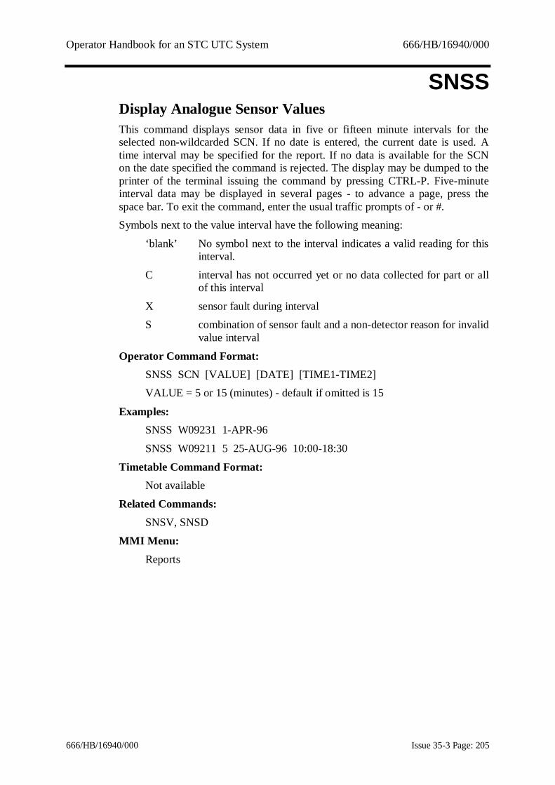
Operator Handbook for an STC UTC System 666/HB/16940/000
666/HB/16940/000 Issue 35-3 Page: 205
SNSSDisplay Analogue Sensor ValuesThis command displays sensor data in five or fifteen minute intervals for theselected non-wildcarded SCN. If no date is entered, the current date is used. Atime interval may be specified for the report. If no data is available for the SCNon the date specified the command is rejected. The display may be dumped to theprinter of the terminal issuing the command by pressing CTRL-P. Five-minuteinterval data may be displayed in several pages - to advance a page, press thespace bar. To exit the command, enter the usual traffic prompts of - or #.Symbols next to the value interval have the following meaning:
‘blank’ No symbol next to the interval indicates a valid reading for thisinterval.
C interval has not occurred yet or no data collected for part or allof this interval
X sensor fault during intervalS combination of sensor fault and a non-detector reason for invalid
value interval
Operator Command Format:SNSS SCN [VALUE] [DATE] [TIME1-TIME2]VALUE = 5 or 15 (minutes) - default if omitted is 15
Examples:SNSS W09231 1-APR-96
SNSS W09211 5 25-AUG-96 10:00-18:30
Timetable Command Format:Not available
Related Commands:SNSV, SNSD
MMI Menu:Reports

Operator Handbook for an STC UTC System 666/HB/16940/000
666/HB/16940/000 Issue 35-3 Page: 206
SNSVDisplay Current Sensor ValuesThis command displays the current values for the specified environment sensors.Optionally a type can be specified and only the sensors of that type are displayed.
Operator Command Format:SNSV SENSOR.SCN [TYPE]
Examples:SNSV W00000
SNSV W00000 CO
Timetable Command Format:Not available
Related Commands:SNSD, SNSS
MMI Menu:Reports

Operator Handbook for an STC UTC System 666/HB/16940/000
666/HB/16940/000 Issue 35-3 Page: 207
SORTSort Controller Checks MessagesThis facility sorts messages produced by the controller checks program for thespecified days into SCN order and then displays them. The controller checksmessages output for each SCN include those generated by operator requestedchecks as well as timetable checks.
The files containing the controller checks messages are kept for the same numberof days as detector data files (configured in database preparation) and are thendeleted.If the second date is omitted then only the data for the first date is processed, ifneither date is specified then today's date is used instead.The output from this command may be redirected to other terminals or printers.See section 9.1.5 for more details.
Operator Command Format:SORT [DATE_1 [DATE_2]]
Examples:SORT 1-May-90 3-May-90SORT 3-May-90
SORT
Timetable Command Format:SORT term
Related Commands:CHCK, XCHC
MMI Menu:Admin

Operator Handbook for an STC UTC System 666/HB/16940/000
666/HB/16940/000 Issue 35-3 Page: 208
SSGMLog stage timings data to data fileThis command starts the logging of stage timings data to a data file for a specifiedintersection or pelican.
The log records observed stage green and intergreen times for controllers, andvehicle, not-vehicle and, if available, pedestrian green times for pedestrian signalcontrollers. The observed cycle time is also displayed.Every hour, the log will record the number of appearances of each stage seen overthe hour.A start time is defaulted to the current time. If no end time is specified, thelogging terminates after 24 hours. Logging also terminates if the number of freedisc blocks drops below 1500.
If a database update (UPDA) that requests a system shutdown occurs whilstlogging is active, then the logging will be suspended during the shutdown and willthen resume. The log will indicate such events.If no parameters are entered all the currently active stage monitors are displayed.
The DSSG command may be used to print the contents of a logging file. TheXSSG command is used for terminating stage timings logging before the canceltime.Up to 10 equipments per TCC may have their stage timings data loggedsimultaneously. Logging files are kept for the number of days specified in thedatabase; after this time has elapsed they are automatically deleted.
Operator Command Format:SSGM SCN [END TIME]
Examples:SSGM J03113 16:45
SSGM J03113
Timetable Command Format:TIME SSGM SCN [END TIME]
Related Commands:DSSG, XSSG
MMI Menu:Faults

Operator Handbook for an STC UTC System 666/HB/16940/000
666/HB/16940/000 Issue 35-3 Page: 209
SSPCSend message to SIESPACE Car Park PCThis command sends messages to the Siespace Car park PC. A detector countmessage can be sent by specifying a detector SCN and the number of vehiclescounted by the detector.The specified detector should be configured on the Siespace PC as either a carpark entry or exit detector. The command is intended to be used for forcing a carpark state by being able to set the car park count to either full (by sending a highdetector count for an entry detector) or empty (by sending a high detector countfor an exit detector). The detector SCN does not need to be configured in the UTCdatabase but must be defined in the Siespace PC database (though the sub-areapart of the detector SCN must be valid).
Operator Command Format:SSPC [DET.SCN] [COUNT]
Examples:SSPC D11881 200
Timetable Command Format:Not available
Related Commands:None
MMI Menu:Not available

Operator Handbook for an STC UTC System 666/HB/16940/000
666/HB/16940/000 Issue 35-3 Page: 210
SSSUStart SCOOT surveyA SCOOT Survey is used to determine a Links LPU Count. When used with theLink SCN and Minutes parameters (see example 1) this command starts a SCOOTSurvey on the link with a duration of 30 minutes.When used with only the Link SCN parameter (see example 2) a SCOOT Surveystarts on the link with a duration of one hour. If a SCOOT Survey is already inprogress it is cancelled and restarted.
If the link becomes faulty the Survey is cancelled. The command is rejected if thenumber of simultaneous SCOOT surveys (up to 16) is exceeded.
During the time the survey is running on the computer an on-street engineershould count the number of vehicles on the link. At the end of the period of thesurvey the LPU count is written to the database against the count detectorassociated with this link. The ASLD command must subsequently be used tocalibrate the link using the on-street vehicles count.
SCOOT Detector CalibrationThe following steps describe the process in calibrating a SCOOT detector forvehicle counts using an example link (N12341A) and count detector (D12351):
i. Define a pseudo count detector (Format Type 0) in the Data BasePreparation form "Count Detector". (In the example, create count detectorD12351).
ii. Synchronise the start of an on-street vehicle count for the link to becalibrated (N12341A for the example) and the SSSU command. Forexample, start both the on-street vehicle count and SSSU at 10:00 precisely,and both for the same interval of time. For a 30 minute interval this wouldbe:
SSSU N12341A 30iii. At the end of the interval, the on-street value is noted down (320, for
example). The SSSU lpu count is stored automatically by the UTC system.iv. Assign the SCOOT link to the count detector using the ASLD command.
The parameters are the SCOOT link, the pseudo count detector and the on-street vehicle count. The command for the example would be:
ASLD N12341A D12351 320v. To verify the conversion factor being used, enter the command LLCF for
either the link or the detector:LLCF N12341A
LLCF D12351vi. The link and pseudo count detector are now associated, and the pseudo
count detector stores vehicle counts in exactly the same manner as a real

Operator Handbook for an STC UTC System 666/HB/16940/000
666/HB/16940/000 Issue 35-3 Page: 211
detector. All the display commands (FLOW, SURV, WEEK and OPFD)show data as for normal count detectors.
Operator Command Format:SSSU N01414A [TIME PERIOD] (TIME PERIOD 1-60 minutes)
Examples:SSSU N01414A 30SSSU N01414A
Timetable Command Format:TIME SSSU SCN [TIME PERIOD]
Example:16:04 SSSU N01414A 30
Related Commands:ASLD, LLCF
MMI Menu:Admin

Operator Handbook for an STC UTC System 666/HB/16940/000
666/HB/16940/000 Issue 35-3 Page: 212
STCSList car park, car park sign, diversion sign and specialfacility statusThis command lists the status of car parks, car park signs, diversions and specialfacilities. Wildcarded SCNs may be specified if desired. The status informationfor car parks includes such items as the current occupancy, the thresholds, and itsoverall state (SPACES, FULL etc.). For signs and special facilities the currentstate is shown and whether the equipment is under operator control. For diversionsigns the active state is shown; i.e. ON or OFF.For a STCS command in the timetable a terminal number, where the data is to beoutput, must be specified.The output from this command may be redirected to other terminals or printers.See section 9.1.5 for more details.
Operator Command Format:STCS SCN
Examples:STCS C79134STCS S79136
STCS V12441
Timetable Command Format:TIME STCS SCN TERM
Example:16:04 STCS C79129 T02001
Inverse Command:None but listings may be terminated by <CTRL> O (non-MMI)
Related Commands:CLOS, OPEN, SIGN, XSIG, CHAN, VALU
MMI Menu:Car Parks
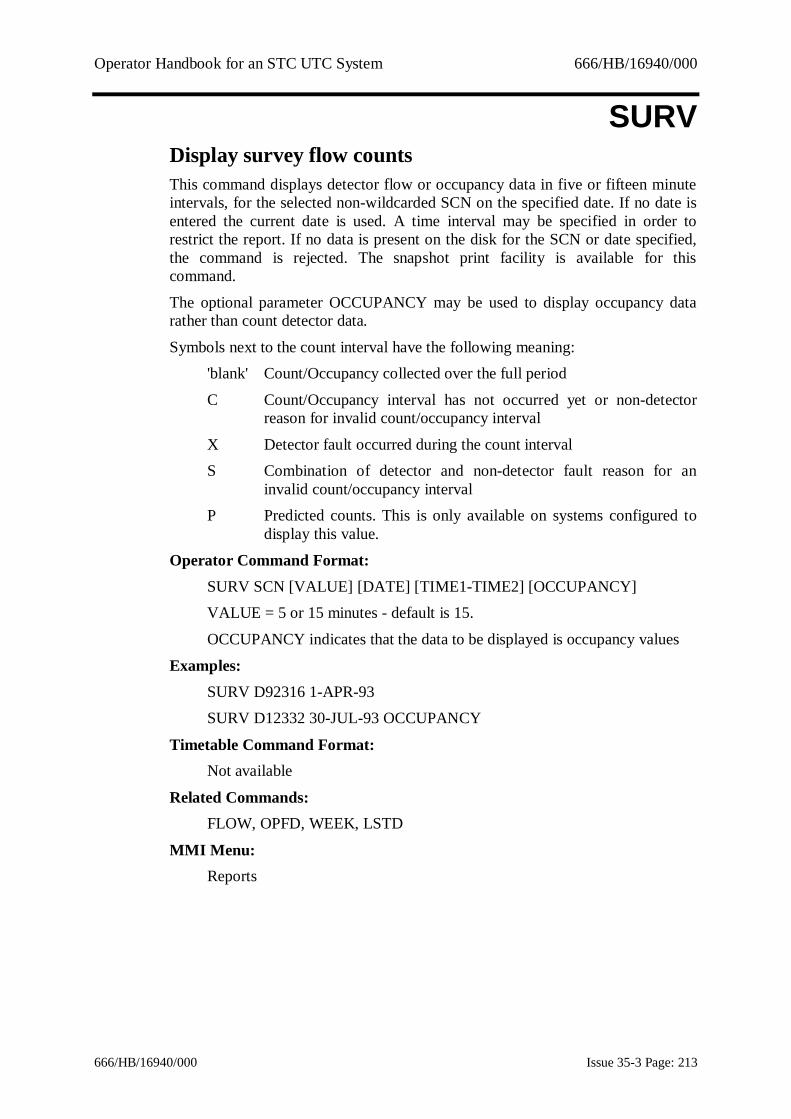
Operator Handbook for an STC UTC System 666/HB/16940/000
666/HB/16940/000 Issue 35-3 Page: 213
SURVDisplay survey flow countsThis command displays detector flow or occupancy data in five or fifteen minuteintervals, for the selected non-wildcarded SCN on the specified date. If no date isentered the current date is used. A time interval may be specified in order torestrict the report. If no data is present on the disk for the SCN or date specified,the command is rejected. The snapshot print facility is available for thiscommand.
The optional parameter OCCUPANCY may be used to display occupancy datarather than count detector data.
Symbols next to the count interval have the following meaning:'blank' Count/Occupancy collected over the full period
C Count/Occupancy interval has not occurred yet or non-detectorreason for invalid count/occupancy interval
X Detector fault occurred during the count intervalS Combination of detector and non-detector fault reason for an
invalid count/occupancy intervalP Predicted counts. This is only available on systems configured to
display this value.
Operator Command Format:SURV SCN [VALUE] [DATE] [TIME1-TIME2] [OCCUPANCY]VALUE = 5 or 15 minutes - default is 15.
OCCUPANCY indicates that the data to be displayed is occupancy values
Examples:SURV D92316 1-APR-93SURV D12332 30-JUL-93 OCCUPANCY
Timetable Command Format:Not available
Related Commands:FLOW, OPFD, WEEK, LSTD
MMI Menu:Reports

Operator Handbook for an STC UTC System 666/HB/16940/000
666/HB/16940/000 Issue 35-3 Page: 214
SUTTSupersede TimetableThis command enables a currently running timetable to be superseded by a newtimetable. The new timetable operates until midnight, until superseded by anothertimetable or until the System is re-booted.A suitable entry is made in the System Log.
Operator Command Format:SUTT VALUE
VALUE = a valid timetable number
Example:SUTT 5
Timetable Command Format:Not available
Related Commands:OUTT
Inverse Command:XSUT
MMI Menu:Manager

Operator Handbook for an STC UTC System 666/HB/16940/000
666/HB/16940/000 Issue 35-3 Page: 215
SYNCSynchronise group timersThis command causes the SG bit to be sent to all controllers that have this bitconfigured so that equipment may be synchronised.
Operator Command Format:SYNC
Example:SYNC
Timetable Command Format:TIME SYNC
Example:16:30 SYNC
MMI Menu:Not available

Operator Handbook for an STC UTC System 666/HB/16940/000
666/HB/16940/000 Issue 35-3 Page: 216
TAPSStart APS in test modeThis command is used to enable automatic fixed-time plan change decisions intest mode. These decisions are based on queue, volume and congestioninformation. While in test mode no plan changes are actually implemented,instead messages are output detailing which plan would have been selected. APSremains implemented until cancelled by an XTAP command. While in test modethe SAPS command is inhibited.
The volume and queue detectors may have test values assigned to them while intest mode by entering the required data as parameters to the TAPS command:
1) Using the command with a volume detector SCN, VALUE is a one-minute count.
2) With a queue detector SCN, VALUE is either ON or OFF.3) Enable by sub-area by specifying a sub-area SCN (not wildcarded).
4) Enable by equipment by specifying an intersection, pelican or diversionSCN that may be wildcarded.
This command may be cancelled automatically using the command cancelfacility. See Section 9.1.6 for details.
Operator Command Format:TAPS [sub_area_SCN] [equipment_SCN] [VALUE] [TIME}
If the sub-area SCN is input then no further parameters are allowed, i.e.APS is put into test mode.
If the sub-area SCN is omitted then an equipment SCN and data valueMUST be input.
Equipment types may be either: count (flow) detectors or queue detectors.Valid data is: 0-213 vehicles/minute (for counts)
Examples:1 -TAPS D03251 10 (10 vehicles/min at detector D03251)
2 -TAPS Q12121 ON (turns on the queue detector Q12121)3 -TAPS A12000 (enables automatic fixed time plan change decisions
in test mode for A12000)4 -TAPS J12000 (enables automatic fixed time plan change decisions
for all junctions with J12000).TAPS D03251 12:00
Timetable Command Format:TIME TAPS sub_area_SCN
Example:16:24 TAPS A02000

Operator Handbook for an STC UTC System 666/HB/16940/000
666/HB/16940/000 Issue 35-3 Page: 217
Related Command:XAPS
Inverse Command:XTAP
MMI Menu:Traffic - Specials

Operator Handbook for an STC UTC System 666/HB/16940/000
666/HB/16940/000 Issue 35-3 Page: 218
TDDDTime/Distance diagram displayThis command is used to create, modify, delete and display the time/distancediagrams either on PC compatible terminals or on graphics terminals. Please referto section 7 for details.This facility allows the monitoring of current plan timings (including SCOOT)and prediction of the outcome of new plan timings.On multi-computer Systems the required computer SCN must be entered.
Operator Command Format:TDDD [SCN]
Example:TDDD
Timetable Command Format:Not available
Inverse Command:None
MMI Menu:Traffic, Normal

Operator Handbook for an STC UTC System 666/HB/16940/000
666/HB/16940/000 Issue 35-3 Page: 219
TESTTest Wall map or alarm panelThis command has 2 modes:a) if NAME = MAP, lights all the wall map indicators until cancelled by theXTES command when they return to their correct states.b) if NAME = ALM, tests the lamps and audible alarms on the alarm panel. TheSystem light and audible alarm come on for three seconds after which theoperational light and audible alarm come on for three seconds. The sequencecontinues until cancelled by the -XTES command. The watch dog lamp stays onfor the duration of the test. If ALL is specified, the alarms on all TCCs are tested,otherwise only the alarms on the TCC on which the command is entered aretested.
Operator Command Format:TEST NAME (NAME = "MAP" or "ALM")
Examples:TEST ALM [ALL]
TEST MAP
Timetable Command Format:Not available
Inverse Command:XTES
MMI Menu:Admin

Operator Handbook for an STC UTC System 666/HB/16940/000
666/HB/16940/000 Issue 35-3 Page: 220
TIDLStart Tidal Flow controlThis command causes the UTC System to take control of the Tidal Flow Schemeand order a change of TFS aspect. Direction may take the values IN (inbound)OUT (outbound) XX (double cross) or EMERGENCY (emergency close of centrelane).
Direction may be abbreviated to I, O, X or E.If direction is omitted then the current state of control is output to the current orspecified terminal using the same mnemonics as above for direction plus LOCALfor a controller which is not under UTC control.
Operator Command Format:TIDL SCN [direction]
Examples:TIDL L05111 IN
TIDL L05111
Timetable Command Format:TIME TIDL SCN [direction]
Example:07:12:30 TIDL L05111
Inverse Command:XTID
MMI Menu:Traffic - Specials

Operator Handbook for an STC UTC System 666/HB/16940/000
666/HB/16940/000 Issue 35-3 Page: 221
TIMEDisplay or modify current timeThis command displays and allows you to change the time and/or date used by theSystem and stored in the battery maintained clock. If neither parameter is enteredthe current date and time are displayed. If only one parameter is entered, thatparameter changes while the other remains the same.
This option is allowed on all terminals allowing UTC or SCOOT commands.On completion, the following message is output:
OLD hh:mm:ss.tt DD-MM-YY NEW hh:mm:ss.tt REQ hh:mm:ss.ttwhere: OLD the old time;
NEW the new time;REQ the requested time;
hh hours;mm minutes;
ss seconds;tt ticks.
WARNING: Archived files may be lost if the date is advanced.
Operator Command Format:TIME [TIME] [DATE]
Examples:TIME 12:00:37TIME
Timetable Command Format:Not available
Related Commands:DATE
MMI Menu:Manager

Operator Handbook for an STC UTC System 666/HB/16940/000
666/HB/16940/000 Issue 35-3 Page: 222
TRAPSet Tram PriorityThis command causes the system to set the tram priority for a junction to AM orPM peak. The SCN may be wild carded.
Note: The AM and PM bits are mutually exclusive. For example, if a junction hasthe AM bit set, setting the PM bit will cause the AM bit to be cleared.
Operator Command Format:TRAP SCN AM|PM
Examples:TRAP J04211 AM
TRAP J04000 PM
Timetable Command Format:TIME TRAP SCN AM|PM
Example:06:00 TRAP J00000 AM
Inverse Command:XTRA
MMI Menu:Traffic

Operator Handbook for an STC UTC System 666/HB/16940/000
666/HB/16940/000 Issue 35-3 Page: 223
TROFDisable output of unsolicited messages to terminalThis command disables output of System (unsolicited) messages to the specifiedterminal or printer. Output requested by a user on the device (i.e. solicited output)such as fault listings is unaffected.NOTE: This command cannot be used to disable the System Log printer. Thecommand XPRI should be used instead.This command may be cancelled automatically using the command cancelfacility. See Section 9.1.6 for details.
Operator Command Format:TROF [TERM] [TIME}
Example:TROF T01001TROF T01001 12:00
Timetable Command Format:TIME TROF TERM
Example:07:12:30 TROF T01001
Inverse Command:XTRO
MMI Menu:Admin

Operator Handbook for an STC UTC System 666/HB/16940/000
666/HB/16940/000 Issue 35-3 Page: 224
TSYNImplement Immediate Time SynchronisationThis command allows the operator to implement time synchronisationimmediately.
This command can be actioned from the timetable or operator command. It is onlyfor systems with an external clock connected.
Operator Command Format:TSYN
Example:TSYN
Timetable Command Format:TIME TSYN
MMI Menu:Manager

Operator Handbook for an STC UTC System 666/HB/16940/000
666/HB/16940/000 Issue 35-3 Page: 225
TTBPStart Timetable Preparation ProcessThis command starts the timetable preparation process. If the command is enteredfrom an X windows based UTC session, the windows version of this process isstarted. More than one user can use the windows timetable preparation process atthe same time; non-windows timetable preparation may only be used by one userat a time.Timetable Preparation cannot be run while another user is running DBAS orTUAC.Context sensitive help for the windows version is available from within theprogram.In the non-windows version, the top-level menu displayed after the process hassuccessfully started contains the following options. Select from this menu byentering the first letter of the option required.
List Timetable Data File to printer -displays a menu from which one or more timetable source filesmay be selected and then printed to the Traffic System printeror listed on the terminal.
Edit Timetable Data Files -displays a menu from which timetable source data may beselectively edited. Time of day timetables (T) or day ofweek/date of year schedules (W) may be edited.
The Edit Time of Day Timetable Data option allows you to usethe EDT editor to edit the contents of a TODnn.MAC file. Youare prompted to enter the number (nn) of the Time of Daytimetable file you wish to edit. After pressing <RETURN> amessage informs you that a temporary copy of the file is beingmade for editing. The data preparation program then transfers tothe EDT editor program to allow the file to be edited. Onleaving the editor you are returned to the Date Preparation Editmenu.The Edit Day of Week/Date of Year Timetable Data optionallows you to use the EDT editor to edit the contents of theXXXTTB.MAC file. After pressing <RETURN> a messageinforms you that a copy of the file is being made for editing.The data preparation program then transfers to the EDT editorprogram allow the file to be edited. On leaving the editor youare returned to the Data Preparation Edit Menu.
Process Timetable Data File -displays a menu from which the timetable source data may beselectively checked and processed. The UPDA command isused to make the data "live". One or more time of daytimetables or the day of week/date of year schedule may be

Operator Handbook for an STC UTC System 666/HB/16940/000
666/HB/16940/000 Issue 35-3 Page: 226
processed. After processing, any errors may be listed to theterminal or printer, or both. Errors from the last run ofprocessing may be listed by selecting the List Errors option.
Temporary Files -When Timetable data is modified a separate temporary file iscreated to hold the modified data. If changes are retained afterediting the data, then the temporary file is retained. Onreturning to re-edit data for which a temporary file exists youare given the option of restoring the original data and deletingthe temporary file, or making further changes to the temporaryfile.
When processing is carried out on modified data it is thetemporary file which is processed. If processing is successfulthe old data file is deleted and the temporary (modified) databecomes the current data. If processing is not successful thenboth the original and temporary files are left on the System. Onexiting Timetable Preparation, if a temporary data file stillexists you are prompted to delete or keep the file.
For a full description of the use of this command, see the separate TimetablePreparation Handbook, reference 1.3.2(k).
Operator Command Format:TTBP
Example:TTBP
Timetable Command Format:None
Related Commands:DBAS, TUAC, UPDA
MMI Menu:Manager
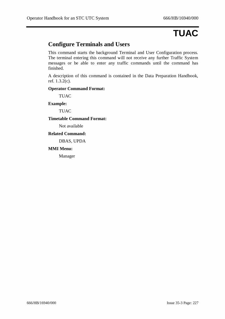
Operator Handbook for an STC UTC System 666/HB/16940/000
666/HB/16940/000 Issue 35-3 Page: 227
TUACConfigure Terminals and UsersThis command starts the background Terminal and User Configuration process.The terminal entering this command will not receive any further Traffic Systemmessages or be able to enter any traffic commands until the command hasfinished.
A description of this command is contained in the Data Preparation Handbook,ref. 1.3.2(c).
Operator Command Format:TUAC
Example:TUAC
Timetable Command Format:Not available
Related Command:DBAS, UPDA
MMI Menu:Manager

Operator Handbook for an STC UTC System 666/HB/16940/000
666/HB/16940/000 Issue 35-3 Page: 228
TUNLChange Tunnel Lane Flow DirectionThis command is used to direct a tunnel controller to change the tunnel lane flowdirection signs for the requested direction
The directions that may be requested depend on the system configuration buttypically the allowed directions are NFLOW (normal flow), CFLOW (contra-flow), or XX (lane closed). If the direction is omitted the current state of thetunnel controller is shown.
Operator Command Format:TUNL SCN [Direction]
Example:TUNL L05111 CFLOW
TUNL L05111
Timetable Command Format:TIME TUNL SCN [Direction]
Example:07:12:30 TUNL L05111
Related Command:XTUN
MMI Menu:Traffic - Specials

Operator Handbook for an STC UTC System 666/HB/16940/000
666/HB/16940/000 Issue 35-3 Page: 229
TXDFTransfer Data File to PC Compatible TerminalThis command transfers a file to a PC. It is only valid for a correctly configuredMMI or directly connected PC and is available by Operator, Timetable or CASTcommand.The TXDF command may also be used to transfer files into the Export directoryon the TMC, from whence they may be copied.The type of file transferred may be one of those listed under “FILE_TYPE”.
For weekly data files the selected date is converted to the previous Monday andspecifies the file to be transferred. The date parameter is not appropriate when theOTU FILE_TYPE is used, and an outstation SCN must be provided. In addition,the date parameter cannot be used in timetables and CASTs. The files are kept forone month on the System.For weekly and daily detector counts, and weekly car park occupancy data,automatic conversion of the data files to DBASE IV format is available bysupplying the parameter DBASE on the command line. For daily detector countsconversion to a format suitable for input into the TRANSPAC PC application isavailable by supplying the parameter TRANSPAC on the command line. Eventmessage data is already in DBASE format and does not require the conversionparameter.
The PC terminal SCN specifies the PC to which the data transfer will take place.This is mandatory when the terminal on which the command is entered is not aPC.The TRANSPAC data files produced are in the following format:
· Each data file contains data for any number of sites. The first record of eachsite's data starts with *BEGIN and contains the file number and site referencenumber, which are the only variable items of information. The first field after*BEGIN is 00 followed by the file number and the file reference number. Thenext eight records contain the data for one day. The first six characters containthe date in the format yymmdd, followed by the end time of the first timeperiod in the format hhmm. Where the record contains count or car park data,the flows for each of the next twelve 15 minute periods are then given. Theneach subsequent day's data for the remainder of the week is given. At the endof each site's data is the *END record, which is a repeat of the first record. Thenext site's data follows in similar format.
Should the PC inadvertently become disconnected during the file transfer process,the CTERM or MMI session on the PC should be restarted before attempting thetransfer again.An ESS licensable facility allows the TXDF command to transfer data of varioustypes for a single site or a group of sites (using wild carded SCNs) to the PC. If asingle site or group of sites is selected for data transfer the data conversion must be setto DBASE The types of data which may be transferred with this facility are:
COUNT_DATA

Operator Handbook for an STC UTC System 666/HB/16940/000
666/HB/16940/000 Issue 35-3 Page: 230
DAILY_COUNT
CARPARK_DATACPP_DATA
ENVIRONENVWEEK
Operator Command Format:TXDF FILE_TYPE [SCN] [CONVERSION] [DATE] [>PC_SCN]or
TXDF OTU [OTU_SCN] [DATE] [>PC_SCN]where:
FILE_TYPE:COUNT_DATA for weekly detector count files (abbrev. CO)
CARPARK_DATA for weekly car park occupancy files (abbrev.CA)
LOG for current daily system log (abbrev. L)DAILY_COUNT for daily detector count files (abbrev. D)
mxx for event message files, where “m” is a letter and“xx” a number
CPP_DATA for daily car park occupancy prediction data(abbrev. CP)
SCOOT_LOG for current daily SCOOT Log (abbrev. S)ENVIRON for daily environmental sensor file (abbrev.
ENVI)ENVWEEK for weekly environmental sensor file (abbrev.
ENVW)FLOW_DATA For detector flow data in dBase format with a
layout similar to that output from the OPFDcommand (abbrev FLO)
ASTRID For extracted ASTRID data in Lotus123 formatonly. Files of format ASddmmyy.123 mustalready exist in the ASTRID_OUTPUT directory
CONVERSION: DBASETRANSPAC (daily detector files only)
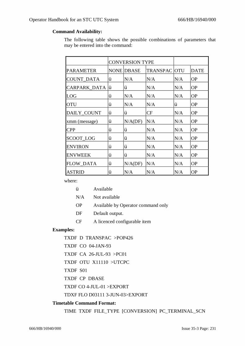
Operator Handbook for an STC UTC System 666/HB/16940/000
666/HB/16940/000 Issue 35-3 Page: 231
Command Availability:The following table shows the possible combinations of parameters thatmay be entered into the command:
CONVERSION TYPE
PARAMETER NONE DBASE TRANSPAC OTU DATE
COUNT_DATA ü N/A N/A N/A OP
CARPARK_DATA ü ü N/A N/A OP
LOG ü N/A N/A N/A OP
OTU ü N/A N/A ü OP
DAILY_COUNT ü ü CF N/A OP
xmm (message) ü N/A(DF) N/A N/A OP
CPP ü ü N/A N/A OP
SCOOT_LOG ü ü N/A N/A OP
ENVIRON ü ü N/A N/A OP
ENVWEEK ü ü N/A N/A OP
FLOW_DATA ü N/A(DF) N/A N/A OP
ASTRID ü N/A N/A N/A OP
where:
ü AvailableN/A Not available
OP Available by Operator command onlyDF Default output.
CF A licenced configurable item
Examples:TXDF D TRANSPAC >POP426TXDF CO 04-JAN-93
TXDF CA 26-JUL-93 >PC01TXDF OTU X11110 >UTCPC
TXDF S01TXDF CP DBASE
TXDF CO 4-JUL-01 >EXPORTTDXF FLO D03111 3-JUN-03>EXPORT
Timetable Command Format:TIME TXDF FILE_TYPE [CONVERSION] PC_TERMINAL_SCN
Operator Handbook for an STC UTC System 666/HB/16940/000
666/HB/16940/000 Issue 35-3 Page: 232
or
TIME TXDF OTU OTU_SCN PC_TERMINAL_SCN
Examples:02:00 TXDF CO PC01
02:50 TXDF CARPARK_DATA PC0106:00 TXDF M14 UTCPC
11:00 TXDF A01 PC0112:20 TXDF OTU X01230 UTC_02
Related Commands:None
MMI Menu:Admin

Operator Handbook for an STC UTC System 666/HB/16940/000
666/HB/16940/000 Issue 35-3 Page: 233
UCOFUse car park occupancy fileThis command instructs the System to use a specified car park occupancy fileinstead of weighted average data for calculation of occupancy predictions. Thecommand is available to the operator and from the timetable and when entered isenforced for the remainder of the day. Wildcards are not permitted in the car parkSCN.The command is journalled.
If 0 is input as the file number, the previous UCOF command is cancelled.
Operator Command Format:UCOF CAR_PARK_SCN FILE_NUMBER
Example:UCOF C07311 10
Timetable Command Format:TIME UCOF CAR_PARK_SCN FILE_NUMBER
Timetable Example:07:00 UCOF C07311 10
Inverse Command:see above
Related Commands:DCOF, LCOF, RCOF
MMI Menu:Car Parks, Special Data

Operator Handbook for an STC UTC System 666/HB/16940/000
666/HB/16940/000 Issue 35-3 Page: 234
UDDLDownload data to an outstationThe command UDDL is followed by the SCN of the controller in question andany of the parameters available. The parameters are the same as for the UploadData Command (UDUL) except that it is not possible to download a fault log.The data to be downloaded is that taken from the file containing the current ormost recently edited outstation data.For a parameter group to be downloaded to the outstation, it must first have beenuploaded from the instation and edited. If the file has not been edited since it wasuploaded, a warning is displayed to the user with the option to exit withoutdownloading the unchanged data to the outstation.Items within the data file which are normally “Read Only” Handset items areignored and not downloaded to the outstation.A status message is produced to indicate the success or failure of the download ofeach data group to each outstation.Download of Level 3 Data items is controlled on a system wide basis and isconfigured as part of the UTC System Configuration. If Level 3 Download isdisabled then Level 3 Data items are filtered from the download message and notsent to the controller.
Operator Command Format:UDDL [OTU_SCN] [DATA_CATEGORY_1] [...[DATA_CATEGORY]]
Examples:UDDL X00000 ALLUDDL X01120 CLF
Timetable Command Format:TIME UDDL X01120 TIME CLF
Inverse Command:None
Related Commands:UDFV
MMI Menu:Traffic, Upload/Download

Operator Handbook for an STC UTC System 666/HB/16940/000
666/HB/16940/000 Issue 35-3 Page: 235
UDFVFault Log viewer for uploaded fault logsThe fault log viewer is a program that allows the operator to view previouslyuploaded controller and OTU fault logs (by UDUL..FAULT_LOG).Thiscommand is only allowed on X terminals.The command UDFV prompts the user to state which fault log he/she wishes toview. If none are entered, the most recently uploaded fault log is displayed for theoperator.
A fault log must be Uploaded using the UDUL command before any can beviewed using the UDFV command.
Up to two sets of fault log flags OR fault log data can be displayed, but notsimultaneously, for visual comparison. The visual comparison takes the form oftwo display areas within a window with the first or most recent fault log displayedon the right and the second on the left. Each display area uses separate scroll barswhere required to move up and down within the individual display. If noparameters are entered, the most recently uploaded fault log flags are displayedfor the SCN in question. If the [DATA] parameter is not included, then fault logflags are displayed by default.
The display text consists of the FLF / FLD numbers and the associated parameterfrom the fault log.
Operator Command Format:UDFV [OTU_SCN] [Fault Log1] [Fault Log2] [DATA]
Examples:UDFV X40150 01/02/95 DATA
UDFV X01120
Timetable Command Format:Not available
Inverse Command:None
Related Commands:UDUL, LSTF
MMI Menu:Traffic, Upload/Download

Operator Handbook for an STC UTC System 666/HB/16940/000
666/HB/16940/000 Issue 35-3 Page: 236
UDLCUpload/Download Line Check and ConfigurationThis command is used to check that all the OTUs on a line have the correct lineconfiguration and, if they are different, update them with the values from thedatabase. The facility downloads the OTU group and then checks that thefollowing items match the values configured in the UTC database - number ofOTUs on the line, number of control bytes for each OTU on the line, number ofreply bytes for each OTU on the line. These are the items accessed by the GNO,GCW and GRW handset commands respectively.Because changing these parameters can affect one-second communications,continuous mode is used for upload/download operations even if this is not theselected transfer mode.
This command is intended especially for those times when, say, the number ofreply bytes is changed on one OTU. Running this command for the OTU willautomatically update all other OTUs on the line. Upload/download must beenabled on OTUs for this facility to check and configure them otherwise normalmanual configuration procedures must be used.
Operator Command Format:UDLC [OTU_SCN]
Examples:UDLC X01120
Timetable Command Format:Not available
Related Commands:UDUL, UDDL, UDRH, UDSL
MMI Menu:Traffic - Upload/Download

Operator Handbook for an STC UTC System 666/HB/16940/000
666/HB/16940/000 Issue 35-3 Page: 237
UDMCModify Upload/Download transfer modeThe command UDMC is used to configure communication lines to a particularmode of Upload/Download operation. The communication line is identified by theTC12PC SCN and the modem number. If all modems on a particular PC are to beconfigured to one mode of operation, then entering ALL instead of the modemnumber configures all the modems attached to the TC12 PC. Wildcarding of theTC12 PC SCN is permitted. This configures all modems on every TC12 PC to themode of operation selected.The system default mode of operation for Upload / Download is defined in theUTC System configuration file. The modes of operation for Upload / Downloadavailable on any system are stored in the UTC System configuration file.The modes of operation (subject to system configuration) are identified by themnemonics detailed below:
· SPLIT Split Second Mode
· ONE One Second in N Mode
· CONT Continuous ModeA status message is output if a particular line configuration could not be carriedout successfully.The value of N for use with the One Second in N mode (ONE) is set as part of theSystem Wide variants screen of the UTC Data Preparation facility. This figure issubject to a lower limit of 4 and upper limit of 30.
Operator Command Format:UDMC [PC_SCN] [MODEM_LINE] [ [TRANSFER_MODE]UDMC [PC_SCN] ALL [TRANSFER_MODE]UDMC [PC_SCN] [TRANSFER_MODE]
Examples:UDMC E00000 CONTUDMC E01001 ALL ONEUDMC E01002 2 SPLIT
Timetable Command Format:Not available
Inverse Command:None
Related Commands:UDUL, UDDL, UDRH
MMI Menu:Traffic, Upload/Download

Operator Handbook for an STC UTC System 666/HB/16940/000
666/HB/16940/000 Issue 35-3 Page: 238
UDRHRemote Handset facilityThe Remote Handset is a program that allows the operator to send OTU andcontroller handset commands to an OTU and displays the OTU’s responses. Thiscommand is only available on systems which have the upload/download facilityenabled. The OTU additionally must have been configured within datapreparation as supporting upload/download.Multiple users can use the Remote Handset for OTUs on different TC12 modemlines but not for OTUs on the same line. Additionally the Remote Handset cannotbe used on an OTU if an upload/download transfer (UDDL, UDUL) is in progresson the same line as the OTU.The command UDRH is followed by the SCN of the outstation to which a remotehandset session is being established. This starts a separate window with a portiondisplaying the recently entered commands and a second portion being used todisplay output from the controller. Scroll bars allow viewing of historic data, withup to 250 lines “off the top” being retained for viewing by “scrolling”.
The UDRH display may be exited by using either the F10 key or the <Control D>key combination.
Refer to the OTU and controller handbooks for information on the availablehandset commands.
Operator Command Format:UDRH [OTU_SCN]
Example:UDRH X01120
Timetable Command Format:Not available
Inverse Command:None
Related Commands:UDUL, UDDL, UDSL
MMI Menu:Traffic, Upload/Download

Operator Handbook for an STC UTC System 666/HB/16940/000
666/HB/16940/000 Issue 35-3 Page: 239
UDSLList Upload/Download statusThis listing command shows the upload/download status of the specifiedcontrollers or modem lines. The listing shows whether any upload/downloadoperations are in progress and, if so, which application is using the line.If a PC SCN is entered, a modem line number or “ALL” must be entered. Thelisting for the modem lines also includes the current transfer mode selected for theline.
Operator Command Format:UDSL [OTU_SCN] [LINE_NUMBER]
Examples:UDSL X00000
UDSL E01001 1UDSL E00000 ALL
Timetable Command Format:10:00 UDSL X00000 >Terminal_SCN
Inverse Command:None
Related Commands:UDUL, UDDL, UDRH
MMI Menu:Traffic, Upload/Download
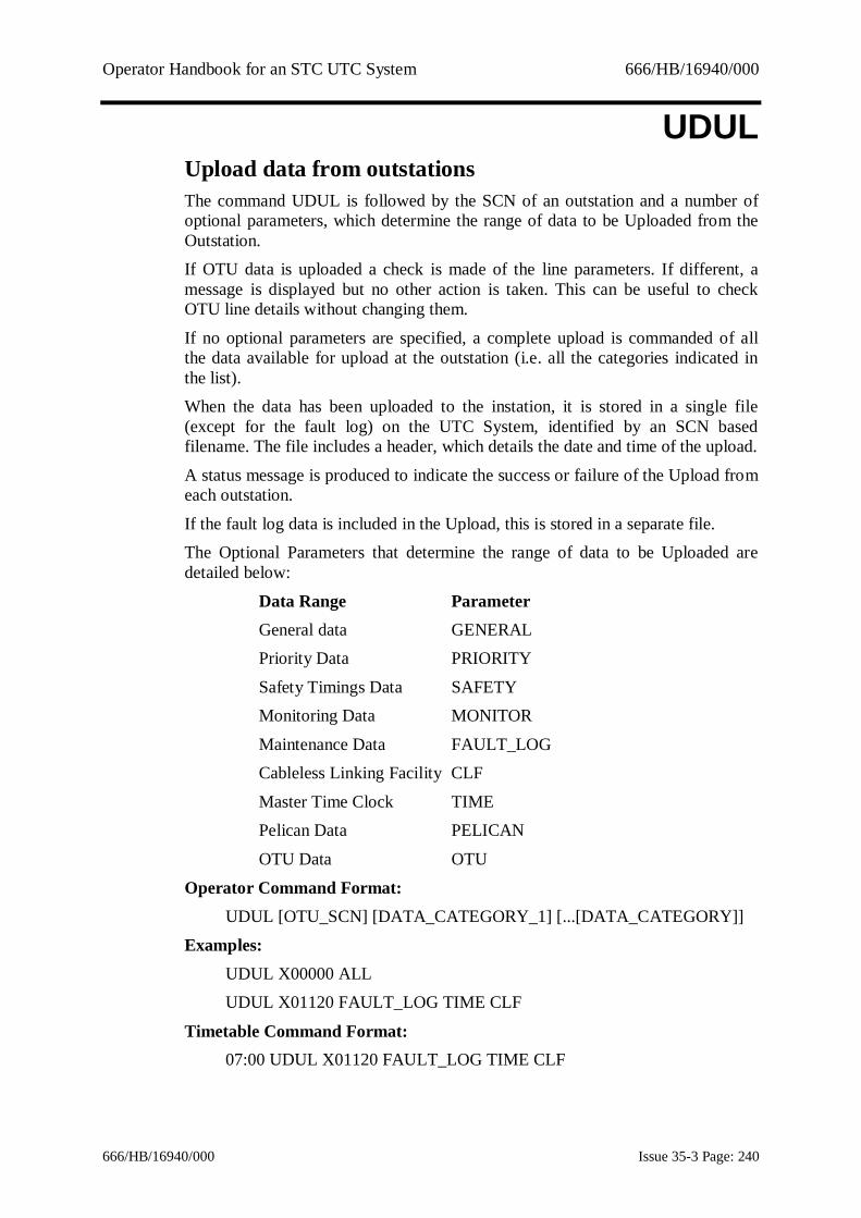
Operator Handbook for an STC UTC System 666/HB/16940/000
666/HB/16940/000 Issue 35-3 Page: 240
UDULUpload data from outstationsThe command UDUL is followed by the SCN of an outstation and a number ofoptional parameters, which determine the range of data to be Uploaded from theOutstation.If OTU data is uploaded a check is made of the line parameters. If different, amessage is displayed but no other action is taken. This can be useful to checkOTU line details without changing them.
If no optional parameters are specified, a complete upload is commanded of allthe data available for upload at the outstation (i.e. all the categories indicated inthe list).When the data has been uploaded to the instation, it is stored in a single file(except for the fault log) on the UTC System, identified by an SCN basedfilename. The file includes a header, which details the date and time of the upload.
A status message is produced to indicate the success or failure of the Upload fromeach outstation.
If the fault log data is included in the Upload, this is stored in a separate file.The Optional Parameters that determine the range of data to be Uploaded aredetailed below:
Data Range ParameterGeneral data GENERALPriority Data PRIORITY
Safety Timings Data SAFETYMonitoring Data MONITOR
Maintenance Data FAULT_LOGCableless Linking Facility CLF
Master Time Clock TIMEPelican Data PELICAN
OTU Data OTU
Operator Command Format:UDUL [OTU_SCN] [DATA_CATEGORY_1] [...[DATA_CATEGORY]]
Examples:UDUL X00000 ALLUDUL X01120 FAULT_LOG TIME CLF
Timetable Command Format:07:00 UDUL X01120 FAULT_LOG TIME CLF

Operator Handbook for an STC UTC System 666/HB/16940/000
666/HB/16940/000 Issue 35-3 Page: 241
Inverse Command:None
Related Commands:UDDL, UDRH, UDSL
MMI Menu:Traffic, Upload/Download

Operator Handbook for an STC UTC System 666/HB/16940/000
666/HB/16940/000 Issue 35-3 Page: 242
UPDAIntroduce updated databasesThis command causes the System to install all updated database modules that areresident in the 'pending' disc directories of the traffic computer. Only thosemodules that have more recent time-stamps than the modules currently being usedare installed. The following optional parameters may be specified.
· 'USERS' to update user configuration data
· 'TIMINGS' to update junction and pelican timings
· 'SCOOT' to update SCOOT data
· 'TIMETABLES' to update timetables only
· 'DESCRIPTIONS' to update equipment descriptions
· 'DST' to update daylight saving start and end dates
· 'ALL' to update all databases (this is the same as no parameter)
· 'SMOOTH' to update only the data that may be updated smoothly
· ‘JOURNAL/NOJOURNAL’ specifies the command journal action
· ‘RESTORE’ undoes the last UPDA command
If 'ALL' is selected the relevant Traffic System closes down and restarts shortlyafterwards. Appropriate messages inform you of the System state. This cancelsany commands with a cancel timer set.If only timetables are updated, it is not necessary for the relevant traffic System tobe closed down. If a new timetable is selected, an entry is placed in the SystemLog.
JOURNAL and NOJOURNAL have the same effect as ALL except thatJOURNAL specifies the command journal should be used to restore the systemstate if UPDA needs to closedown the system. NOJOURNAL specifies that thejournal should be cleared and the system state should be restored from thetimetable. At present, UPDA ALL is equivalent to UPDA NOJOURNAL.RESTORE undoes the last UPDA command. That is, it loads the databasemodules that were in use prior to the last UPDA command. This option is onlyavailable to licensed customers (such as customers with ESS).On completion of the update, the message 'Database update complete' is output.This message is also output if no changes are required.Note: Installing SCOOT data implicitly includes a re-initialisation of the
SCOOT database (see the REIN command).
Operator Command Format:UPDA [PARAM]PARAM = one of TIMETABLES | ALL | SMOOTH | SCOOT | TIMINGS |
USERS | DESCRIPTIONS | DST | JOURNAL |NOJOURNAL | RESTORE

Operator Handbook for an STC UTC System 666/HB/16940/000
666/HB/16940/000 Issue 35-3 Page: 243
Examples:UPDAUPDA SMOOTH
Timetable Command Format:Not available
Related Commands:DBAS, TUAC, REIN
MMI Menu:Manager

Operator Handbook for an STC UTC System 666/HB/16940/000
666/HB/16940/000 Issue 35-3 Page: 244
VALUList value of SCOOT parameterThis command is used to list the value of a SCOOT or UTC parameter in thedatabase. The parameters that can be listed are defined in Appendix B. WildcardSCNs are permitted as for the CHAN command. The SCOOT SCN parameter isrequired for all commands except those at area level. SCOOT parameters aredetailed in the SCOOT User Guide, ref. 1.3.2(e). The UTC parameters aredescribed in section 10.
The output from this command may be redirected to other terminals or printers.See section 9.1.5 for more details.
Operator Command Format:VALU PARAM [ScSCN]
Examples:VALU JNYT N23121A
VALU TREN RLLVALU STOC N**
Timetable Command Format:TIME VALU PARAM [ScSCN] TERM
Examples:09:00 VALU ADJU T01004
08:00 VALU JNYT N23121A T0100416:30:20 VALU TREN RLL T03001
08:00:10 VALU STOC N** T02002
Related Commands:SEES, CHAN
MMI Menu:Car Parks/SCOOT

Operator Handbook for an STC UTC System 666/HB/16940/000
666/HB/16940/000 Issue 35-3 Page: 245
VARYVary stage green timesThis command brings up a Plan Preparation screen. The view window contains adata history of the last 10 changes to the plan currently running for the SCN. Anedit window appears which contains the TEST plan for the controller. This maythen be changed in the same way as with Plan Preparation.
An optional removal time may be specified for this command, to the nearestminute.
This command may only be entered when a fixed time plan is active. If the planchanges while the display is active, the plan is not implemented when terminatethe display.
Operator Command Format:VARY SCN [TIME]
Examples:VARY J03181VARY J03181 08:10
Timetable Command Format:Not available
Related Commands:PPRP, XPLA, OFST
MMI Menu:Traffic - Normal

Operator Handbook for an STC UTC System 666/HB/16940/000
666/HB/16940/000 Issue 35-3 Page: 246
VEGADisplay SCOOT link profile and queueThis command allows you to display the demand profiles and stop-line queues onup to 4 SCOOT links. If a single link SCN is entered a more detailed display isgiven. Optionally a single link SCN with the link part only wildcarded and thenode specified may be entered. In this case the display is for the first four links onthe node.While the display is running the terminal is prevented from outputting any Systemmessages and all traffic commands are inhibited. The display is cancelled by theentry of another traffic prompt on the same terminal.
The display is presented in the form of 2 histograms.The upper histogram shows the flow of vehicles in red (when the lights for thislink are red) and green (when the lights are green) on the vertical axis against thecycle time of the region which contains the upstream node of the link on thehorizontal. Each bar of the histogram representing 4 seconds duration. If thedownstream link is exit blocked then the flow bars are displayed in magenta.
The lower histogram shows in blue the proportion of the maximum queue cleartime the queue requires to discharge. Each bar of the histogram represents 4seconds duration. The horizontal axis shows the cycle time of the region thatcontains the upstream node of the link. If the link being displayed is a filter thishistogram is not updated.Screen dump facilities are available. <CTRL> P (non-MMI terminal) dumps thepicture in to the printer associated with the terminal issuing the command.
Operator Command Format:VEGA ScSCN [ScSCN] [ScSCN] [ScSCN]
Examples:VEGA N04331A N04331BVEGA N04351J
VEGA N04341*
Timetable Command Format:Not available
MMI Menu:SCOOT

Operator Handbook for an STC UTC System 666/HB/16940/000
666/HB/16940/000 Issue 35-3 Page: 247
WAVCList weighted averages tableThis command causes the contents of the weighted averages table to be listed for aspecified car park. The specified SCN may not be wildcarded.
This may only be used for car parks of type 2 and 3.The output from this command may be redirected to other terminals or printers.See section 9.1.5 for more details.
Operator Command Format:WAVC SCN
Example:WAVC C79245
Timetable Command Format:Not available
MMI Menu:Reports

Operator Handbook for an STC UTC System 666/HB/16940/000
666/HB/16940/000 Issue 35-3 Page: 248
WEEKDisplay weekly detector flow countsThis command causes the System to display the hourly counts collected overseven days for the specified detector SCN. The SCN may not be wildcarded.
If the date is not specified the current day and the previous six days are displayed.If a date is specified that day and the following six days are displayed. If data forthe date entered in the command does not exist on disk, then the command isrejected.
The optional parameter OCCUPANCY may be added to display occupancy datarather than count detector data.
Letters used against the values are:'blank' Count collected over the full period
c Data unavailable for some or all of the periods Counts unavailable for some or all of the period due to fault
condition(s).p No count data available for the current day and so data from a
previous week has been substituted.
Operator Command Format:WEEK SCN [DATE] [OCCUPANCY]OCCUPANCY indicates that the data to be displayed is occupancy values
Examples:WEEK D09231 1-APR-93
WEEK D09111 30-JUL-93 OCCUPANCY
Timetable Command Format:Not available
Related Commands:FLOW, OPFD, SURV, EDAV, LSTD
MMI Menu:Reports

Operator Handbook for an STC UTC System 666/HB/16940/000
666/HB/16940/000 Issue 35-3 Page: 249
WHATList equipmentThis command causes the System to list all equipment matching the specifiedSCN. This command is useful in finding out exactly what equipments are in aparticular sub-area etc.The SCN may be wildcarded. WHAT supports the use of parent/child wildcardedSCOOT SCNs.If the sub-area equipment type (letter A) is given, ALL equipment types thatmatch the SCN are displayed. Unwanted output can be disposed of with theCTRL-O (non-MMI) facility as described in section 9.1.4.
An optional text string can be added to the command that causes only those SCNswith the text string in their description to be output. If the text string is in quotesspaces are allowed.A “Sort by SCN” button is available on the WHAT display listing window. Thisallows the output to be sorted by SCN.The output from this command may be redirected to other terminals or printers.See section 9.1.5 for more details.
Operator Command Format:WHAT SCNWHAT SCN text
WHAT SCN "text"
Examples:WHAT C00000 (Display all car parks)WHAT S70300 (All car park signs in sub-area 70 group 3)
WHAT A01100 "east bound"WHAT RAA>
WHAT N40121<>
Timetable Command Format:Not available
Inverse Command:None but listings may be terminated by <CTRL> O (non-MMI)
MMI Menu:Info

Operator Handbook for an STC UTC System 666/HB/16940/000
666/HB/16940/000 Issue 35-3 Page: 250
XACCDelete CAST Association with Region Cycle TimeThis command deletes an association of a CAST with a cycle time made byACCT.
Exactly the same parameters as used in the original ACCT command that madethe association must be used in the XACC command to delete that association.The CAST name and number are, however, interchangeable.The LACC command may be used to find which associations exist.
See help on ACCT for more information.
Operator Command Format:XACC castname Region_SCN Region_Cycle_Time +|-XACC castnumber Region_SCN Region_Cycle_Time <+|-
Example:XACC 101 RCA 56 -
XACC am-rush-clear-crossing2 RCA 56 +
Timetable Command Format:TIME XACC RAB 123
Related command:LACC, ACCT
MMI Menu:SCOOT / SCOOT Specials

Operator Handbook for an STC UTC System 666/HB/16940/000
666/HB/16940/000 Issue 35-3 Page: 251
XACSCancel ACSV CommandThis command removes the on the off casts and timer periods associated with agiven group though a previous ACSV command.
Operator Command Format:XACS SCN GROUP
Example:XACS H01000 3
Timetable Command Format:TIME XACS SCN GROUP
Example:22:01 XACS H01000 2
Inverse Command:ACSV
Related Command:LACS
MMI Menu:Traffic / Normal
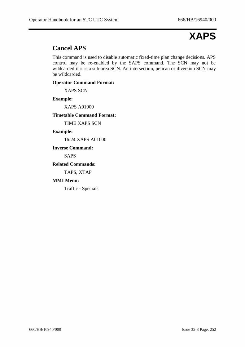
Operator Handbook for an STC UTC System 666/HB/16940/000
666/HB/16940/000 Issue 35-3 Page: 252
XAPSCancel APSThis command is used to disable automatic fixed-time plan change decisions. APScontrol may be re-enabled by the SAPS command. The SCN may not bewildcarded if it is a sub-area SCN. An intersection, pelican or diversion SCN maybe wildcarded.
Operator Command Format:XAPS SCN
Example:XAPS A01000
Timetable Command Format:TIME XAPS SCN
Example:16:24 XAPS A01000
Inverse Command:SAPS
Related Commands:TAPS, XTAP
MMI Menu:Traffic - Specials

Operator Handbook for an STC UTC System 666/HB/16940/000
666/HB/16940/000 Issue 35-3 Page: 253
XARRRemove Association between Remote Request and CASTsThis command removes the association between the Remote Request and theCASTs that had been set up by the ARRQ command.
If the ARRQ that is being removed is active (i.e. the remote request is ON) thenXARR forces the ARRQ to terminate as if the remote request was now off. Afterthe timeout period and running the second removal CAST the ARRQ associationis removed.
Operator and timetable XARR commands have the same priority. Thus anoperator XARR command supersedes a timetable command and vice-versa.
Operator Command Format:XARR SCN
Example:XARR Z03113
Timetable Command Format:TIME XARR SCN
Example:12:00 XARR Z03113
Inverse Command:ARRQ
Related Command:LARR
MMI Menu:Traffic / Specials

Operator Handbook for an STC UTC System 666/HB/16940/000
666/HB/16940/000 Issue 35-3 Page: 254
XASCCancel Action CAST by Saturation/CongestionThis command deletes an event trigger created by ASCCExactly the same parameters as used in the original ASCC command which madethe trigger must be used in the XASC command to delete that trigger.The LASC command may be used to find which associations exist.
See help on ASCC for more information.
Operator Command Format:XASC CAST LinkSCN SATURATION SAT% +|-XASC CAST LinkSCN CONGESTION CONG% +|-
Example:XASC 123 N01231A CONGESTION 56 +
XASC station-rd-oversat_clearing N01231A SATURATION 85 -
Timetable Command Format:As Operator, with TIME prefix.
Inverse Command:ASCC
Related Command:LASC
MMI Menu:Traffic > Specials

Operator Handbook for an STC UTC System 666/HB/16940/000
666/HB/16940/000 Issue 35-3 Page: 255
XAUDDisable audible alarmsThis command causes the operational and/or System audible alarms to remainsilent when an alarm condition is detected. If no alarm condition exists, the status(enabled or disabled) of the operational and/or System alarms is displayed.This command may be cancelled automatically using the command cancelfacility. See Section 9.1.6 for details.
Operator Command Format:XAUD [OP | SYS | BOTH] [TIME]
Examples:XAUD OPXAUD SYS
XAUD BOTHXAUD OP 12:00
Timetable Command Format:TIME XAUD STR
Example:16:24 XAUD BOTH
Inverse Command:AUDI
MMI Menu:Admin

Operator Handbook for an STC UTC System 666/HB/16940/000
666/HB/16940/000 Issue 35-3 Page: 256
XCARCancels car park state controlThis command cancels the operator command CARP, for modifying a car parkstate and restores the car park to its default mode of operation.
Operator Command Format:XCAR SCN
Example:XCAR C07311
Timetable Command Format:TIME XCAR SCN
Example:05:00 XCAR C07311
Inverse Command:CARP
Related Commands:STCS, SIGN
MMI Menu:Car Parks

Operator Handbook for an STC UTC System 666/HB/16940/000
666/HB/16940/000 Issue 35-3 Page: 257
XCHACancels a Priority CHANThis command is used to cancel a CHAN Priority and revert to the lower levelpending value for the specified parameter and SCN. The SCN may be wildcarded.
A valid SCOOT or UTC SCN must be supplied except for Area level parameters.This is a licensed facility (ESS).
Operator Command Format:XCHA PARAM [ScSCN/SCN]
Example:XCHA STOC N10151*
Timetable Command Format:TIME XCHA PARAM SCN
Example:05:00 XCHA STOC N11123*
Inverse Command:CHAN … SUPER
Related Commands:CHAN, LSCH
MMI Menu:SCOOT

Operator Handbook for an STC UTC System 666/HB/16940/000
666/HB/16940/000 Issue 35-3 Page: 258
XCHCStop controller test sequence checkingThis command cancels all junction controller checks currently in progress.
Operator Command Format:XCHC
Example:XCHC
Timetable Command Format:TIME XCHC
Example:05:00 XCHC
Inverse Command:CHCK
MMI Menu:Traffic - Specials

Operator Handbook for an STC UTC System 666/HB/16940/000
666/HB/16940/000 Issue 35-3 Page: 259
XCHGResume normal TCC operationThis command is used to resume normal TCC operation after a CHGO commandhas been used to cause a standby computer to be used in place of a failed TCC.
It should be remembered that the Ethernet connection from the TCC to the TC12PC may need to be moved to allow the repaired computer to resume control of theon-street equipment.Changeover can also be initiated or cancelled by rebooting the standby computerand answering the relevant questions that are asked at startup.
Operator Command Format:XCHG [STANDBY COMPUTER]
Example:XCHGXCHG H03000
Timetable Command Format:Not available
Inverse Command:CHGO
MMI Menu:Manager

Operator Handbook for an STC UTC System 666/HB/16940/000
666/HB/16940/000 Issue 35-3 Page: 260
XCHSStop sign exercisingThis command cancels all sign exercising currently in progress.
Operator Command Format:XCHS
Example:XCHS
Timetable Command Format:TIME XCHS
Example:05:00 XCHS
Inverse Command:CHSI
MMI Menu:Traffic - Specials

Operator Handbook for an STC UTC System 666/HB/16940/000
666/HB/16940/000 Issue 35-3 Page: 261
XCSFDe-select special facilityThis command cancels a special facility. The special facility may have been seteither by the System or by the CSFY command. This command may bewildcarded.
Operator Command Format:XCSF SCN
Example:XCSF F01254
Timetable Command Format:TIME XCSF SCN
Example:05:00 XCSF F01254
Related Commands:SFNO, XSFN
Inverse Command:CSFY
MMI Menu:Traffic - Normal

Operator Handbook for an STC UTC System 666/HB/16940/000
666/HB/16940/000 Issue 35-3 Page: 262
XDEMCancel forced demand(s) on a particular stageThis command allows you to cancel demands that have been previously forced fora stage on a Junction or Pelican by the DEMA command. The SCN may bewildcarded to cancel demands on all Junctions or Pelicans.The stage parameter is optional; if omitted all the demands for stages which areforced using the 'DX' bit are removed. If a stage is specified it must have beenconfigured as a demand dependent stage and the demand for that stage isremoved. Only pelican controllers which have a 'PX' bit may have their demandcancelled by this command.
JunctionConfiguration
Command:
DEMA J12345
Command:
DEMA J12345 A
Command:
DEMA J12345 *
DX only Cancel DX Rejected Rejected
Dn only Rejected Cancel DA Cancel all Dn (but notDX)
Dn and DX Cancel DX Cancel DA Cancel all Dn (but notDX)
Operator Command Format:XDEM SCN [DD_STAGE]
Examples:XDEM J01111 CXDEM J00000
Timetable Command Format:TIME XDEM SCN [DD_STAGE]
Examples:21:45:50 XDEM J01111 C23:30:00 XDEM J00000
Inverse Command:DEMA
Related Command:LSTS

Operator Handbook for an STC UTC System 666/HB/16940/000
666/HB/16940/000 Issue 35-3 Page: 263
MMI Menu:Faults
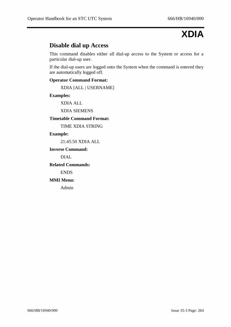
Operator Handbook for an STC UTC System 666/HB/16940/000
666/HB/16940/000 Issue 35-3 Page: 264
XDIADisable dial up AccessThis command disables either all dial-up access to the System or access for aparticular dial-up user.
If the dial-up users are logged onto the System when the command is entered theyare automatically logged off.
Operator Command Format:XDIA [ALL | USERNAME]
Examples:XDIA ALL
XDIA SIEMENS
Timetable Command Format:TIME XDIA STRING
Example:21:45:50 XDIA ALL
Inverse Command:DIAL
Related Commands:ENDS
MMI Menu:Admin

Operator Handbook for an STC UTC System 666/HB/16940/000
666/HB/16940/000 Issue 35-3 Page: 265
XDIMCancel dimming override bitThe command causes the System to cancel the dimming override control bit beingtransmitted to the specified equipment. The SCN may be wildcarded if desired.
Operator Command Format:XDIM SCN
Example:XDIM J01111
Timetable Command Format:TIME XDIM SCN
Example:21:45:50 XDIM J01111
Inverse Command:DIMO
MMI Menu:Traffic - Normal

Operator Handbook for an STC UTC System 666/HB/16940/000
666/HB/16940/000 Issue 35-3 Page: 266
XDISReconnect outstationThis command causes the System to resume transmission of control words to andreceipt of reply words from the specified OTU. The SCN may be wildcarded ifdesired.
Operator Command Format:XDIS SCN
Example:XDIS X01450
Timetable Command Format:Not available
Inverse Command:DISO
Related Commands:ISOL, XISO
MMI Menu:Faults

Operator Handbook for an STC UTC System 666/HB/16940/000
666/HB/16940/000 Issue 35-3 Page: 267
XEMECancel Equipment MessageThis command removes the text of any message associated with an equipmentSCN. If fault category is zero, or omitted, then all messages will be removed,otherwise only the message associated with the optional fault category will beremoved.
Operator Command Format:XEME SCN [VALUE] (VALUE = fault category)
Examples:XEME J03111
XEME J01111 121
Timetable Command Format:23:59 XEME J1111123:00 XEME J05000 113
Related Commands:EMES, LSTF, DIPM, LEME
MMI Menu:Faults

Operator Handbook for an STC UTC System 666/HB/16940/000
666/HB/16940/000 Issue 35-3 Page: 268
XFALClear fall-back mode bitThis command causes the System to cancel the fall-back mode selection controlbit being transmitted to the specified equipment. The SCN may be wildcarded ifdesired.
Operator Command Format:XFAL SCN
Example:XFAL J01124
Timetable Command Format:TIME XFAL SCN
Example:23:50 XFAL J01124
Inverse Command:FALL
MMI Menu:Traffic - Normal

Operator Handbook for an STC UTC System 666/HB/16940/000
666/HB/16940/000 Issue 35-3 Page: 269
XFLACancel flashing amber modeThis command causes the System to cancel a previous operator command, FLASand restores the controller from flashing mode to its default mode of operation.The SCN may be wildcarded. However, if a wildcarded SCN is used, the XFLAcommand is only enabled if all the controllers have the FF bit configured.
Operator Command Format:XFLA SCN
Example:XFLA J11241
Timetable Command Format:TIME XFLA SCN
Example:07:12:30 XFLA J11241
Inverse Command:FLAS
MMI Menu:Traffic – Specials

Operator Handbook for an STC UTC System 666/HB/16940/000
666/HB/16940/000 Issue 35-3 Page: 270
XFLGErase fault category groupThis, optional, command allows you to erase a previously set up fault categorygroup.
Operator Command Format:XFLG nn
Examples:XFLG 1111
Timetable Command Format:Not available
Related Commands:FLTG, LFLG, XFLT
MMI Menu:Admin/Fault groups

Operator Handbook for an STC UTC System 666/HB/16940/000
666/HB/16940/000 Issue 35-3 Page: 271
XFLTCancel faultThis command allows you to clear faults recorded on a particular SCN. The SCNmay be wildcarded if desired. A fault category may be specified which may alsobe wildcarded. If the fault category is omitted, a value of zero (i.e. all faults) isassumed. Faults on the computer or the terminals may not be cleared by use ofthis command.For a list of fault categories, see Appendix C.
Operator Command Format:XFLT SCN [VALUE] (VALUE = fault category)
Examples:XFLT X23310
XFLT J01119 100
Timetable Command Format:TIME XFLT X00000
Inverse Command:FLTY
Related Command:LSTF, FLTG, LFLG, XFLG
MMI Menu:Faults

Operator Handbook for an STC UTC System 666/HB/16940/000
666/HB/16940/000 Issue 35-3 Page: 272
XFTASpecify which Faults should not raise a System AlarmThis command allows an operator to specify which faults shold not raise a systemalarm. A Fault category (which may be wild carded) and, optionally, anequipment type should be specified. The equipment type should be specified byentering an appropriate globally wildcarded SCN. If no equipment type isspecified, the command will operate on all equipment types.
Operator Command Format:XFTA [SCN] FAULT_CATEGORY
Example:XFTA J00000 100FXTA 700
Timetable Command Format:TIME XFTA [SCN] FAULT_CATEGORY
Example:23:00 XFTA J00000 120
Inverse Command:FLTA
MMI Menu:Faults

Operator Handbook for an STC UTC System 666/HB/16940/000
666/HB/16940/000 Issue 35-3 Page: 273
XGWACancel operator green waveThis command cancels a previously requested operator green wave on thespecified SCN. Wildcarded SCNs are not allowed.
Terminals must be specifically configured during terminal data preparation if theywish to use this command.
Operator Command Format:XGWA SCN
Example:XGWA G05119
Timetable Command Format:Not allowed
Related Commands:GWAV, LSTG
MMI Menu:Traffic - Specials

Operator Handbook for an STC UTC System 666/HB/16940/000
666/HB/16940/000 Issue 35-3 Page: 274
XHRYCancel Manual Hurry CallThis command cancels a manual hurry call request for a controller.A maximum of 5 controllers may be specified in one command. SCN must be theSCN of a junction or pelican controller, not wildcarded
Operator Command Format :XHRY SCN [SCN] [SCN] [SCN] [SCN]
Example :XHRY J03111XHRY J03112 P21111
Timetable Command Format :Not available
Related Command :HRYC
MMI Menu :Traffic - Specials
Operator Handbook for an STC UTC System 666/HB/16940/000
666/HB/16940/000 Issue 35-3 Page: 275
XIFTCancel Inhibited FaultThis facility allows the user to cancel faults that have been inhibited by use of theIFLT command.
This is a licenced feature.
Operator Command Format:XIFT [SCN] [Fault_Category]
Examples:XIFTXIFT J01123
XIFT J00000 132
Timetable Command Format:09:34 XIFT J20100
Related Commands:LIFT, IFLT
MMI Menu:Faults

Operator Handbook for an STC UTC System 666/HB/16940/000
666/HB/16940/000 Issue 35-3 Page: 276
XIHPRe-enable plan compliance fault isolationThis command cancels the inhibition of plan compliance fault isolation of ajunction or pelican controller. The wildcard 120 may be used with junction or sub-area SCNs but not pelicans. Omitting the fault category has the same effect.The particular fault categories for junctions and sub-area SCNs are 121 - plancompliance fault and 122 - wrong stage returned; for pelicans only plancompliance fault 122 is available.
Operator Command Format:XIHP SCN [Fault_Number]
Example:XIHP J05119 121
Timetable Command Format:TIME XIHP SCN Fault_Number
Example:10:20:40 XIHP J13221 121
Inverse Command:IHPC
Related Command:LSTS
MMI Menu:Faults

Operator Handbook for an STC UTC System 666/HB/16940/000
666/HB/16940/000 Issue 35-3 Page: 277
XIHRRe-enable reply word analysisThis command cancels the inhibition of reply word analysis (i.e. enables it) on theequipment specified. The equipment SCN may not be wildcarded.
Operator Command Format:XIHR SCN
Example:XIHR J05119
Timetable Command Format:TIME XIHR SCN
Inverse Command:IHRW
Related Commands:DISO, XDIS, ISOL, XISO
MMI Menu:Faults

Operator Handbook for an STC UTC System 666/HB/16940/000
666/HB/16940/000 Issue 35-3 Page: 278
XIHTCancel Tram Priority InhibitionThis command cancels the inhibition of tram priority as set by the INTPcommand. The junction SCN may be wild carded. The required TI bit must bespecified.
Operator Command Format:XIHT SCN <TI bit>
Examples:XIHT J04211 2
XIHT J00000 4
Timetable Command Format:TIME XIHT SCN <TI bit>
Example:15:55 XIHT J00000 1
Inverse Command:IHTP
MMI Menu:Traffic
Operator Handbook for an STC UTC System 666/HB/16940/000
666/HB/16940/000 Issue 35-3 Page: 279
XINHCancel inhibition of weekly flow analysisThis command cancels the weekly flow analysis inhibit flag for the specifieddetector SCN (which may not be wildcarded). Output can again be produced forthe site when an OPFD command is entered.
Operator Command Format:XINH SCN
Example:XINH D92315
Timetable Command Format:TIME XINH SCN
Example:10:20:40 XINH D92315
Related Commands:INHW, OPFD
MMI Menu:Reports

Operator Handbook for an STC UTC System 666/HB/16940/000
666/HB/16940/000 Issue 35-3 Page: 280
XISOCancel controller isolationThis command cancels the isolation of the specified controller (or controllers ifthe SCN is wildcarded). Its control bits return to normal.
Operator Command Format:XISO SCN
Example:XISO J09000
Timetable Command Format:TIME XISO SCN
Example:15:30 XISO J09000
Inverse Command:ISOL
Related Commands:DISO, XDIS
MMI Menu:Faults

Operator Handbook for an STC UTC System 666/HB/16940/000
666/HB/16940/000 Issue 35-3 Page: 281
XLIVStart simulation of an equipmentNOTE: This is an unsupported feature for use by STC maintenance engineers.This command starts simulation of the specified equipment. The valid equipmenttypes are outstations, junctions, pelicans, special facilities, count detectors,SCOOT detectors, queue detectors, car parks, car park signs and diversion signs.If a computer SCN is entered then an outstation address must be specified. If theequipment is an outstation or outstation address then simulation is started for allequipment on the outstation. The SCN may be wildcarded except for computerSCNs.
Operator Command Format:XLIV COMPUTER_SCN ADDRESS
XLIV SCN
Examples:XLIV J11241XLIV X00000
XLIV H01000 12
Timetable Command Format:Not available
Inverse Command:LIVE
Related Command:SIMU
MMI Menu:Not available

Operator Handbook for an STC UTC System 666/HB/16940/000
666/HB/16940/000 Issue 35-3 Page: 282
XLLNCancel local link inhibit bitThis command cancels the transmission of the local link inhibit control bit to thespecified controller (or controllers if the SCN is wildcarded).
Operator Command Format:XLLN SCN
Example:XLLN J01111
Timetable Command Format:TIME XLLN SCN
Example:15:30 XLLN J01111
Inverse Command:LLNK
MMI Menu:Traffic - Normal
Operator Handbook for an STC UTC System 666/HB/16940/000
666/HB/16940/000 Issue 35-3 Page: 283
XLOTCancel logging of OTU control and reply bitsThis command terminates the logging of data for a particular OTU (started usingthe LOTU command).
Any equipment SCN that has an OTU associated with it, or a computer SCN maybe entered, followed by an outstation address.
The SCN or address specified may not be wildcarded.
Operator Command Format:- Common format
XLOT SCN
- Telecommand 8 SystemXLOT COMPUTER_SCN ADDRESS
- Telecommand 8 OTUs on a Telecommand 12 PCXLOT PC_SCN ADDRESS
- Telecommand 12 OTUsXLOT PC_SCN TC12_MODEM ADDRESS
Examples:XLOT X01450
XLOT H01000 145XLOT E01001 123
XLOT E01001 5 16
Timetable Command Format:- Common format for all Systems
TIME XLOT SCN
- Telecommand 8 SystemTIME XLOT COMPUTER_SCN ADDRESS
- Telecommand 8 OTUs on a Telecommand 12 PCTIME XLOT PC_SCN ADDRESS
- Telecommand 12 OTUsTIME XLOT PC_SCN TC12_MODEM ADDRESS
Examples:16:20 XLOT X01450
15:00 XLOT H01000 14512:30 XLOT E01001 123
18:00 XLOT E01001 5 16

Operator Handbook for an STC UTC System 666/HB/16940/000
666/HB/16940/000 Issue 35-3 Page: 284
Inverse Command:LOTU
Related commands:DLOT, MONI, OVRB
MMI Menu:Faults

Operator Handbook for an STC UTC System 666/HB/16940/000
666/HB/16940/000 Issue 35-3 Page: 285
XMESStop output of event messageThis command terminates the output of selected event driven messages. The listof event driven messages is given in reference 1.3.2(e).
If the name ALL is given in place of the name of an event message then all eventdriven messages currently active on the nominated terminal are cancelled. This isa quick way of clearing up after validation.An optional parameter may be used to cancel output to the ASTRID computer orto an archive file or SCOOT log. The output from this command may beredirected to other terminals or printers. See section 9.1.5 for more details.
Operator Command Format:XMES NAME ScSCN [>ASTRID]
NAME = message name (see reference 1.3.2(e)) or "ALL"
Examples:XMES M14 N04141AXMES C05 RLL >ASTRID
XMES ALLXMES M14 N04161A >ARCHIVE
XMES M14 N04161A >SCOOT_LOG
Timetable Command Format:TIME XMES NAME ScSCN TERM | ASTRID
Examples:15:15 XMES M14 N04141A T0100515:20:30 XMES C05 RLL ASTRID
Inverse Command:MESS
Related Commands:LSTM
MMI Menu:SCOOT

Operator Handbook for an STC UTC System 666/HB/16940/000
666/HB/16940/000 Issue 35-3 Page: 286
XMOVRemove a Moveable Count Detector from an OTUThis command cancels the effect of the MOVE command.The command removesa Type 8 (Moveable) count detector from its currently allocated OTU. Thedetector will cease counting and not resume until allocated to another OTU bymeans of the MOVE command.
Note: This is a licenceable facility.
Operator Command Format:XMOV {DETECTOR}
Example:XMOV D88111
Timetable Command Format:TIME XMOV SCN
Example:08:30 XMOV D88111
Related Command:MOVE
MMI Menu:Traffic, Specials

Operator Handbook for an STC UTC System 666/HB/16940/000
666/HB/16940/000 Issue 35-3 Page: 287
XMVACancel MOVA Control ModeThis command causes the system to cancel a previous operator command, MOVAand restores the controller from MOVA control to its default mode of operation.
The SCN may be wildcarded. However, if a wildcarded SCN is used, the XMVAcommand will only be actioned on the controllers which have the MO bitconfigured.The command is also allowed in timetables or CASTs.
Operator Command Format:XMVA SCN
Example:XMVA J01923
Timetable Command Format:TIME XMVA SCN
Example:08:30 XMVA J01900
Related Command:MOVA
MMI Menu:Traffic, Specials

Operator Handbook for an STC UTC System 666/HB/16940/000
666/HB/16940/000 Issue 35-3 Page: 288
XPLACancel operator fixed-time planThis command removes operator or temporary imposed control (PLAN, VARY orOFFSET) on the SCN specified in the command, and returns the equipment(s) totheir normal time of day control.The SCN may be wildcarded.
Either OPERATOR or TEMPORARY may be specified for the priorityparameter. The default is OPERATOR. See PLAN command description forfurther details of these priority levels.If an operator imposed plan is running and a PLAN command has also beenentered to introduce a further plan at a later time, entry of an XPLA commandcancels both.
Operator Command Format:XPLA SCN
Example:XPLA J01131
Timetable Command Format:TIME XPLA SCN
Example:22:32:15 XPLA J01131
Inverse Command:PLAN
Related Commands:VARY, OFST, LIPT
MMI Menu:Traffic - Normal

Operator Handbook for an STC UTC System 666/HB/16940/000
666/HB/16940/000 Issue 35-3 Page: 289
XPRIDisable log printerThis command turns log printing off, i.e. messages for the System Log are notoutput to the System Log printer.
This command may be cancelled automatically using the command cancelfacility. See Section 9.1.6 for details.
Operator Command Format:XPRI [TIME}
Example:XPRI
XPRI 12:00
Timetable Command Format:TIME XPRI
Inverse Command:PRIN
MMI Menu:Admin

Operator Handbook for an STC UTC System 666/HB/16940/000
666/HB/16940/000 Issue 35-3 Page: 290
XRUBDelete previously RUBAed dataThe RUBA command is used to enter various SCOOT parameters into thebaseline file. The XRUB command may be used to delete data for a specifed SCNand parameter from the baseline file.If the parameter is omitted all data for the specified SCN will be deleted.
Operator Command Format:XRUB [PARAM] SCN
Example:XRUB STOC N12111A
XRUB N12341Z
Timetable Command Format:Not available
Related Commands:RUBA, LUBA, DUBA, CHAN, VALU
MMI Menu:None

Operator Handbook for an STC UTC System 666/HB/16940/000
666/HB/16940/000 Issue 35-3 Page: 291
XSCAAction the CHANs in a selected CAST in Cancel CHANPriority modeThis command causes a selected CAST to be actioned - ie., all the commands inthe CAST will be executed. However, all the CHAN commands in the selectedCAST will be translated into XCHA commands. This is the cancel action to apreviously executed SCAS command. The CAST may be referred to by its nameor by number.
This command is not available in the timetable.This is a licensed facility (ESS).
Operator Command Format:XSCA CAST.IDENTIFIER
Examples:XSCA 16
XSCA ROADWORKS
Timetable Command Format:Not available
Inverse Command:SCAS
Related Commands:CHAN … SUPER, XCHA, ACAS, LCAS, ICAS, DCAS, NCAS
MMI Menu:CASTS

Operator Handbook for an STC UTC System 666/HB/16940/000
666/HB/16940/000 Issue 35-3 Page: 292
XSCOCancel SCOOT controlThis command switches SCOOT control off for a node or region. SCOOT controlmay be re-implemented by a SCOO command. Operator and timetable SCOO andXSCO commands have equal priority.
Operator Command Format:XSCO ScSCN
Examples:XSCO N02331XSCO RHA
Timetable Command Format:TIME XSCO ScSCN
Example:08:00:38 XSCO N02331
Inverse Command:SCOO
MMI Menu:Traffic - Normal/SCOOT

Operator Handbook for an STC UTC System 666/HB/16940/000
666/HB/16940/000 Issue 35-3 Page: 293
XSFNRe-enable special facility selectionThis command cancels the inhibition of a single special facility or range of specialfacilities (wildcarding is allowed). The special facility may have been inhibited bythe SFNO command.
Operator Command Format:XSFN SCN
Examples:XSFN F01112XSFN F01000
Timetable Command Format:TIME XSFN SCN
Example:08:00:38 XSFN F01121
Inverse Command:SFNO
Related Commands:CSFY, XCSF
MMI Menu:Traffic - Normal

Operator Handbook for an STC UTC System 666/HB/16940/000
666/HB/16940/000 Issue 35-3 Page: 294
XSIGCancel sign legend overrideThis command causes the System to cancel the operator imposed car park ordiversion sign legends. The SCN may not be wildcarded.
Operator Command Format:XSIG SCN
Examples:XSIG S70312
XSIG V00000
Timetable Command Format:TIME XSIG SCN
Example:16:33 XSIG S70318
Inverse Command:SIGN
Related Command:STCS
MMI Menu:Traffic - Normal/Car Parks

Operator Handbook for an STC UTC System 666/HB/16940/000
666/HB/16940/000 Issue 35-3 Page: 295
XSLOTurn part time signals onThis command causes the System to enable part time signals that have beendisabled to use the SLOF command.
This command may not be wildcarded.
Operator Command Format:XSLO SCN
Example:XSLO J09231
Timetable Command Format:TIME XSLO SCN
Examples:15:15 XSLO J0923115:20:30 XSLO J09231
Inverse Command:SLOF
MMI Menu:Traffic - Normal

Operator Handbook for an STC UTC System 666/HB/16940/000
666/HB/16940/000 Issue 35-3 Page: 296
XSPOCancel spooled outputThis command cancels spooled output on the configured printers for the terminalwhere the command was entered. The command stops spooled output currently inprogress and any output initiated within the next 10 seconds. Listings or spooledoutput requested after this period are unaffected.
Output to a specific terminal/printer can be cancelled by using the redirectionoperator '>'.
The output from this command may be redirected to other terminals or printers.See section 9.1.5 for more details.
Operator Command Format:XSPO
Example:XSPO
Timetable Command Format:Not available
MMI Menu:Reports/Admin

Operator Handbook for an STC UTC System 666/HB/16940/000
666/HB/16940/000 Issue 35-3 Page: 297
XSSGCancel logging of stage timings dataThis command terminates the logging of intersection/pelican stage timings datainitiated by the SSGM command.
Operator Command Format:XSSG SCN
Example:XSSG J01332
Timetable Command Format:TIME XSSG SCN
Inverse Command:SSGM
Related Command:DSSG
MMI Menu:Faults
Operator Handbook for an STC UTC System 666/HB/16940/000
666/HB/16940/000 Issue 35-3 Page: 298
XSUTCancel all operator timetable overridesThis command cancels the effect of all previously entered SUTT commands. Thetimetable specified by the day-of-week/date-of-year schedules is loaded. The newtimetable is scanned from the start of the day till the current time and is then usedas the current timetable.
When a new timetable is selected an entry is placed in the System Log.
Operator Command Format:XSUT
Example:XSUT
Timetable Command Format:Not available
Inverse Command:SUTT
Related Command:OUTT
MMI Menu:Manager

Operator Handbook for an STC UTC System 666/HB/16940/000
666/HB/16940/000 Issue 35-3 Page: 299
XTAPCancel APS in test modeThis command is used to disable automatic fixed-time plan change decisions inTEST mode. These decisions are based on queue, volume and congestioninformation. While in test mode no plan changes are actually implemented,instead messages are output detailing which plan would have been selected. APStest mode may be re-enabled by the -TAPS command. The SCN may bewildcarded, unless it is a sub-area SCN.
Operator Command Format:XTAP SCN
Example:XTAP A01000
Timetable Command Format:TIME XTAP SCN
Example:15:15 XTAP A01000
Inverse Command:TAPS
Related Commands:SAPS, XAPS
MMI Menu:Traffic - Specials

Operator Handbook for an STC UTC System 666/HB/16940/000
666/HB/16940/000 Issue 35-3 Page: 300
XTESCancel wall map or SIP lamp testThis command cancels all the wall map test indications and restores the lamps totheir correct state. It can also be used to cancel the test of the lamps and theaudible alarms on the alarm panel.
Operator Command Format:XTES NAME (NAME = "MAP" or "ALM")
Examples:XTES MAPXTES ALM
Timetable Command Format:Not available
Inverse Command:TEST
MMI Menu:Admin

Operator Handbook for an STC UTC System 666/HB/16940/000
666/HB/16940/000 Issue 35-3 Page: 301
XTIDCancel Tidal Flow controlThis command removes the specified Tidal Flow controller from UTC control andallows it to revert to Local control.
Operator Command Format:XTID SCN
Example:XTID L05111
Timetable Command Format:TIME XTID SCN
Example:07:12:30 XTID L05111
Inverse Command:TIDL
MMI Menu:Traffic – Specials

Operator Handbook for an STC UTC System 666/HB/16940/000
666/HB/16940/000 Issue 35-3 Page: 302
XTRACancel AM/PM Tram PriorityThis command cancels the AM or PM tram priority bits for the specifiedjunction(s). The SCN may be wild carded
Operator Command Format:XTRA SCN
Examples:XTRA J04211
Timetable Command Format:TIME XTRA SCN
Example:15:55 XTRA J00000
Inverse Command:TRAP
Related Commands:LTRA
MMI Menu:Traffic
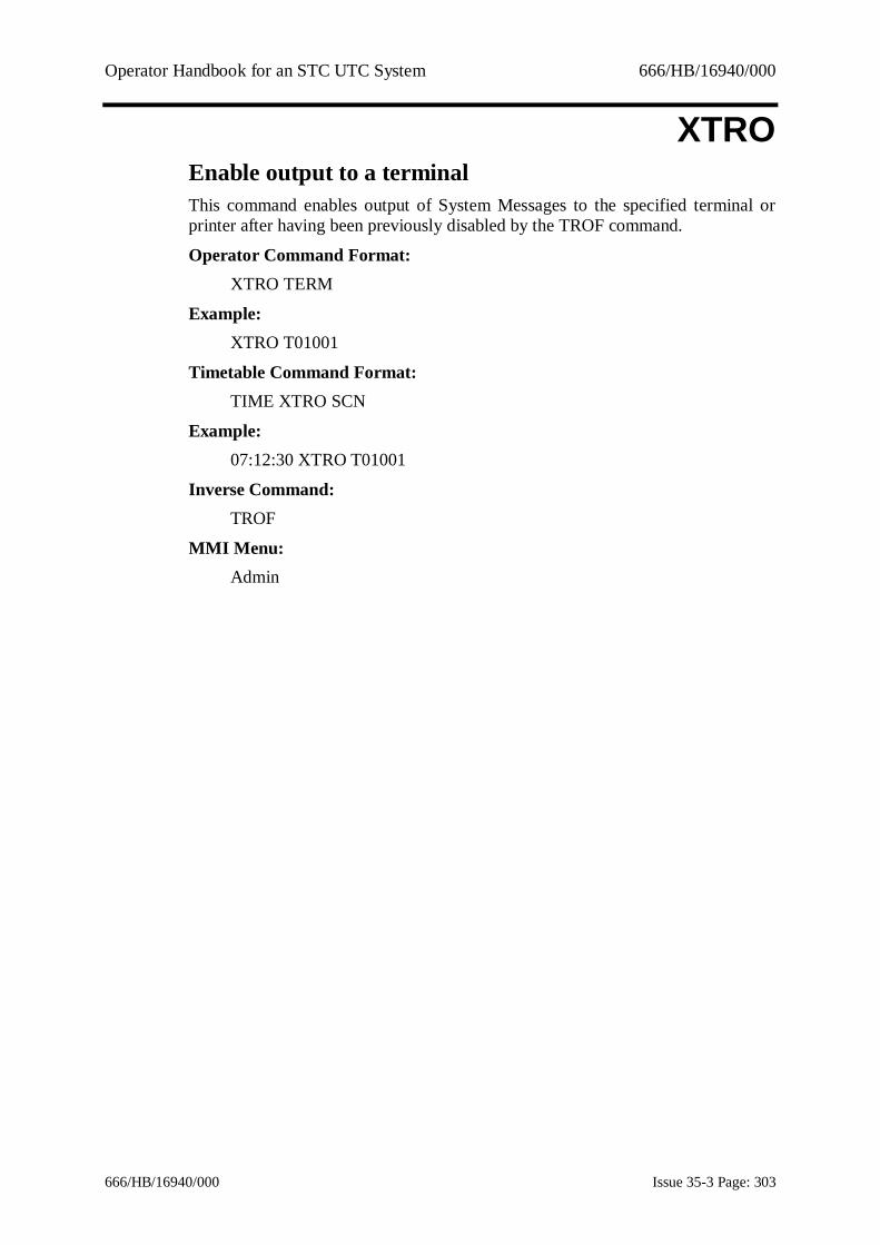
Operator Handbook for an STC UTC System 666/HB/16940/000
666/HB/16940/000 Issue 35-3 Page: 303
XTROEnable output to a terminalThis command enables output of System Messages to the specified terminal orprinter after having been previously disabled by the TROF command.
Operator Command Format:XTRO TERM
Example:XTRO T01001
Timetable Command Format:TIME XTRO SCN
Example:07:12:30 XTRO T01001
Inverse Command:TROF
MMI Menu:Admin

Operator Handbook for an STC UTC System 666/HB/16940/000
666/HB/16940/000 Issue 35-3 Page: 304
XTTCRemove command from Temporary TimeTableThis command This command removes commands from the temporary timetable.Commands that have been entered with a start time are stored in the temporarytimetable (timetable 0) until they are executed. If only a time is entered with theXTTC command then all commands with that time will be deleted. If more thanone command exists for a particular time then a specific command may beremoved by entering the command string for that command. The command stringmust exacltly match the command string that was originally entered.A user may only remove those temporary commands for which he has thenecessary level of acces for him to enter the command originally.
Operator Command Format:XTTC {TIME} [COMMAND STRING]
Examples:XTTC 10:00XTTC 10:15 PLAN J12341 1
Timetable Command Format:Not available
MMI Menu:Admin

Operator Handbook for an STC UTC System 666/HB/16940/000
666/HB/16940/000 Issue 35-3 Page: 305
XTUNCancel Tunnel ControlThis command cancels UTC control on the specified tunnel controller. The tunnelcontroller returns to local control.
Operator Command Format:XTUN SCN
Example:XTUN L05111
Timetable Command Format:TIME XTUN SCN
Example:07:12:30 XTUN L05111
Inverse Command:TUNL
MMI Menu:Traffic - Specials

Operator Handbook for an STC UTC System 666/HB/16940/000
666/HB/16940/000 Issue 35-3 Page: 306
10. UTC VALU/CHAN Parameter DescriptionThis section describes the VALU and CHAN parameters exclusive to UTC. AllSCOOT VALU and CHAN parameter descriptions are contained in the SCOOTUser Guide, ref. 1.3.2(e). All the parameters in this section can be used with bothVALU and CHAN.
AFDT - Almost Full Decreasing ThresholdThis parameter applies to car parks only.Values for CHAN are 0 to AFIT-1.
The Almost Full Decreasing Threshold is used by the system to change the stateof car park signs. If this threshold is crossed with a decreasing vehicle count thesystem changes the appropriate sign(s) state(s) from "ALMOST FULL" to"SPACES" after completing the Change Down Delay for the associated car park.
AFIT - Almost Full Increasing ThresholdThis parameter applies to car parks only.
Values for CHAN are from AFDT to FDTH-1.The Almost Full Increasing Threshold is used by the system to change the state ofcar park signs. If this threshold is crossed with an increasing vehicle count thesystem changes the appropriate sign(s) state(s) from "SPACES" to "ALMOSTFULL".
APSR – Automatic Plan Selection Re-Run IntervalThis parameter sets the minimum interval for plan change under APS. Acceptablevalues are in the range 1 to 120 minutes.
Note that some systems are configured to use the highest cycle time for the re-runinterval.
CACP - Congestion Alarm Clear PercentageThis is a UTC count detector parameter.
This is the percentage congestion at which a count detector congestion alarmclears. It may not be set to more than the Congestion Alarm Set Percentage(CASP) and in this event remains unchanged.
CAPA - Car park capacityThis parameter is for car parks only.Values for CHAN are 0 to the maximum capacity configured for any car park onthe system. This is defined in the UTC FMS form for Car Park Data.

Operator Handbook for an STC UTC System 666/HB/16940/000
666/HB/16940/000 Issue 35-3 Page: 307
CASP - Congestion Alarm Set PercentageThis is a UTC Count Detector command.This is the percentage congestion at which a count detector congestion alarm isset. It may not be set to less than the Congestion Alarm Clear Percentage (CACP)and in this event remains unchanged.
CJNY - VMS to car park or car park group journey time.This parameter is for VMS Car Park signs only.
Values for CHAN are 0 to 3600 sec.
COMM - Override Communications Profile.This parameter is for UTMC type 2 outstations only.Enter the ID of a UTMC2 outstation communications profile. The selected profilewill override the profile specified in the database. If the outstation is currentlyonline, then it will go briefly offline and then come back online using the newprofile which typically takes less than 3 seconds.To cancel the override, enter an ID of 0.
Use of this parameter can be useful when monitoring SCOOT detector replies(e.g. with MONI/LMON) to switch from a profile that batches SCOOT detectordata, to one that doesn't so that data shown is more immediate.
COPS - Car Park Occupancy Prediction Smoothing FactorThis parameter is for car parks only.Values for CHAN are 0 to 100 percent.
This parameter is used in smoothing car park occupancy predictions.
CQT1 - Car Park Queuing Time for Range 1This is a UTC Count Detector command.This is the queuing time, which is reported when the occupancy of a detectorassociated with a car park is in range 1. There are four detector occupancy rangesand the limits for these are defined on the count detector form of data preparation.Note that an occupancy of 0 always reports a queuing time of 0.The four queuing times associated with the occupancy ranges must be inascending order, not overlapping and in the range 1 to 120 minutes. If the queuingtime is set to a value that violates these rules an error is reported and the limitremains unchanged.

Operator Handbook for an STC UTC System 666/HB/16940/000
666/HB/16940/000 Issue 35-3 Page: 308
CQT2 - Car Park Queuing Time for Range 2
CQT3 - Car Park Queuing Time for Range 3CQT4 - Car Park Queuing Time for Range 4See CQT1 for details of these parameters.
DIVR - Automatic Diversion Selection Re-run IntervalThis parameter is only available on those Systems which are configured forautomatic diversion selection.
Values for CHAN are 0 to 60 minutes.This parameter sets the minimum interval between diversion changes whenautomatic diversion selection is being used.
FDTH - Full Decreasing ThresholdThis parameter applies to car parks only.Values for CHAN are AFIT+1 to CAPA-1.
The Full Decreasing Threshold sets the threshold at which a decreasing vehiclecount changes the appropriate car park sign(s) state(s) from "FULL" to"ALMOST FULL" after completing the Change Down Delay for the associatedcar park.
FITH - Full Increasing ThresholdThis parameter applies to car parks only.
Values for CHAN are FDTH+1 to CAPA-1.The Full Increasing Threshold sets the threshold at which an increasing vehiclecount changes the appropriate car park sign(s) state(s) from "ALMOST FULL" to"FULL".
GRET - Green Red entrance thresholdThis parameter applies to car parks only.
Values for CHAN are 0 to CAPA.This parameter is used to set the threshold of vehicles at which an entrance signchanges from "SPACES" to "FULL" (with an increasing vehicle count), or vice-versa for a decreasing vehicle count. The representation of "SPACES" and"FULL" at the entrance sign is system dependent.
GWPL - Green Wave Plan numberThis parameter applies to Green Waves only.Values for CHAN are from 1 to 100.
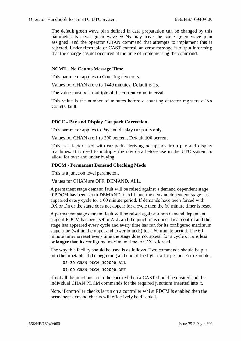
Operator Handbook for an STC UTC System 666/HB/16940/000
666/HB/16940/000 Issue 35-3 Page: 309
The default green wave plan defined in data preparation can be changed by thisparameter. No two green wave SCNs may have the same green wave planassigned, and the operator CHAN command that attempts to implement this isrejected. Under timetable or CAST control, an error message is output informingthat the change has not occurred at the time of implementing the command.
NCMT - No Counts Message TimeThis parameter applies to Counting detectors.
Values for CHAN are 0 to 1440 minutes. Default is 15.The value must be a multiple of the current count interval.
This value is the number of minutes before a counting detector registers a 'NoCounts' fault.
PDCC - Pay and Display Car park CorrectionThis parameter applies to Pay and display car parks only.
Values for CHAN are 1 to 200 percent. Default 100 percentThis is a factor used with car parks deriving occupancy from pay and displaymachines. It is used to multiply the raw data before use in the UTC system toallow for over and under buying.
PDCM - Permanent Demand Checking ModeThis is a junction level parameter..
Values for CHAN are OFF, DEMAND, ALL.A permanent stage demand fault will be raised against a demand dependent stageif PDCM has been set to DEMAND or ALL and the demand dependent stage hasappeared every cycle for a 60 minute period. If demands have been forced withDX or Dn or the stage does not appear for a cycle then the 60 minute timer is reset.A permanent stage demand fault will be raised against a non demand dependentstage if PDCM has been set to ALL and the junction is under local control and thestage has appeared every cycle and every time has run for its configured maximumstage time (within the upper and lower bounds) for a 60 minute period. The 60minute timer is reset every time the stage does not appear for a cycle or runs lessor longer than its configured maximum time, or DX is forced.The way this facility should be used is as follows. Two commands should be putinto the timetable at the beginning and end of the light traffic period. For example,
02:30 CHAN PDCM J00000 ALL
04:00 CHAN PDCM J00000 OFF
If not all the junctions are to be checked then a CAST should be created and theindividual CHAN PDCM commands for the required junctions inserted into it.
Note, if controller checks is run on a controller whilst PDCM is enabled then thepermanent demand checks will effectively be disabled.

Operator Handbook for an STC UTC System 666/HB/16940/000
666/HB/16940/000 Issue 35-3 Page: 310
PFLG - Persistent Fault LogThis parameter determines whether the UTC fault log persists between systemrestarts.
The values for CHAN are: YES and NOIf enabled, then prior to system shutdown, the live fault log is saved to disk.Following the restart, the fault log is reloaded from disk. During startup, thesystem suppresses error reporting for the short period that it takes for outstationsto come online, thereby eliminating temporary startup fault conditions.The persistent fault log feature is a licensed facility. If the feature is licensed thenthe default for this parameter will be YES.
PIGE - Permanent Intergreen Extension LimitThis parameter applies to intersection controllers and sets the number ofconsecutive cycles which are tested for intergreen extensions to their maximumvalue. If the upper and lower intergreen values are the same, no checking isperformed. The range of CHAN values is from 0 (no checking) to 62.
PPEL - Permanent Pedestrian Stage Maximum Extension limitThis parameter applies to pedestrian controllers.
Values to CHAN are 0 to 255.When set to a non-zero value, this parameter is used to detect puffins that alwaysextend the pedestrian stage. This can occur when the puffin pedestrian detector isfaulty.
The check works as follows:Every time the puffin Not-GX stage runs for at least the upper Not-GX time acounter is incremented. When the counter reaches the PPEL value a 'PermanentPedestrian Stage Max Extension' [0464] fault will be raised. If the Not-GX stageruns for less than the upper Not-GX time then the counter is cleared.When set to 0, no checking is performed.
A value of 50 is suggested for this check. This means that if a puffin runs thepedestrian stage to its maximum for 50 times in succession a fault will be raised.
This parameter may not be used on pedestrian controllers for which the upper andlower Not-GX times are the same (i.e. pelicans for which no extension ispossible).
PRTD - Priority Route DurationPriority Routes require an additional license from STCLSpecifies the duration for which the fixed time plan (specified by PRTP) will runwhen triggered by a greenwave. After this time the previous mode of control willbe resumed. The duration may be in the range 1 to 720 seconds. 0 disables priorityroute control, in which case normal greenwave control will apply to thejunction/pelican.

Operator Handbook for an STC UTC System 666/HB/16940/000
666/HB/16940/000 Issue 35-3 Page: 311
The SCN may be specified as junction, pelican, subarea or greenwave. The SCNmay be wildcarded, except for greenwave. A greenwave SCN causes all junctionsand pelicans in the greenwave to be set.
PRTP - Priority Route PlanPriority Routes require an additional license from STCL
The PRTP parameter specifies the Fixed Time plan to run on a controller in placeof normal rolling greenwave control. The plan number may be in the range 1 to40. A value of 0 disables priority route control, in which case normal greenwavecontrol will apply to the junction/pelican.
The SCN may be specified as junction, pelican, subarea or greenwave. The SCNmay be wildcarded, except for greenwave. A greenwave SCN causes all junctionsand pelicans in the greenwave to be set.
SMOO - Smoothing factor for congestionThis is a UTC detector parameter.Values for CHAN are 0 to 99%.
This is a smoothing factor for occupancy from flow detectors. The value "X"allocated to this parameter signifies the occupancy value stored for this detector isX% of the current unsmoothed value and (100-X)% of the accumulated smoothedvalue. 0% means total smoothing, with a stored value constant after a short initialperiod, and 99% stores practically unsmoothed data.
TDS1 -This is a UTC flow detector parameter.Values for CHAN are 0 to 99, in minutes.
TDS2 -This is a UTC flow detector parameter.
Values for CHAN are 0 to 99, in minutes.
TIS1 -This is a UTC flow detector parameter.Values for CHAN are 0 to 99, in minutes.
TIS2 -This is a UTC flow detector parameter.
Values for CHAN are 0 to 99, in minutes.

Operator Handbook for an STC UTC System 666/HB/16940/000
666/HB/16940/000 Issue 35-3 Page: 312
VEHC - Vehicle countThis parameter is for car parks only.Values for CHAN are 0 to CAPA.
This changes the count of vehicles in a car park.
VLAG - Volume alarm lag timeThis is a UTC flow detector parameter.Values for CHAN are 0 to 99, in minutes.
This is the number of continuous minutes, during which the one minute alarmthreshold has been exceeded. Alternatively, it is the number of continuousminutes, during which the count of vehicles does not exceed the one minutethreshold value.
VTHR - One Minute Volume Alarm ThresholdThis is a UTC flow detector parameter.
Values for CHAN are 0 to 99.The VTHR parameter may be used to change the one minute alarm thresholdwhich is set in DBAS. If more than VTHR vehicles are counted in a one minuteperiod the volume alarm may be set.
ZRTM - RTIG Traffic Movement AssociationThis is a pseudo Remote Request parameter
Values for CHAN are 0 to 31This parameter is used in conjunction with ZRTS and ZRTP to associate a remoterequest with the notification of a bus received from an AVL system using theRTIG XML interface.
See the help for ZRTS for an overall summary of the use of these parameters.
ZRTP - RTIG Traffic Point AssociationThis is a pseudo Remote Request parameterValues for CHAN are REGISTER, REQUEST, CLEAR or 0 to 15
This parameter is used in conjunction with ZRTS and ZRTM to associate aremote request with the notification of a bus received from a AVL system usingthe RTIG XML interface.See the help for ZRTS for an overall summary of the use of these parameters.
This parameter associates a particular trigger point with the remote request.Though the AVL interface supports up to 16 trigger points, there are only 3 welldefined ones. These are 'Register' (0) when the bus is approaching the junction atsome distance, 'Request' (1) when the bus is nearer the junction and is requesting

Operator Handbook for an STC UTC System 666/HB/16940/000
666/HB/16940/000 Issue 35-3 Page: 313
immediate priority and 'Clear' (2) when the bus has cleared the junction. An AVLsystem may not implement all these trigger points though, typically, 'Request' willalways be supported and this is the default value.
ZRTS - RTIG Traffic Signal Number AssociationThis is a pseudo Remote Request parameter
Values for CHAN are 0 to 16383This parameter is used in conjunction with ZRTM and ZRTP to associate aremote request with the notification of a bus received from an AVL system usingthe RTIG XML interface.
Normally, RTIG bus notifications are associated with SCOOT links (via theBTSN and BTSM parameters) for SCOOT bus priority. However, to allowalternative actions to be taken, for example, to enable local bus priority at non-SCOOT sites, RTIG notifications can be associated with a pseudo remote request.(A pseudo remote request is one that is not configured on an outstation). When anotification matching the selection criteria is seen, the pseudo remote request is'set' for 3 seconds. Any actions associated with the remote request - such as settinga special facility, or calling a CAST (ARRQ) - will be initiated.
When the AVL system detects a bus approaching a junction, it supplies the trafficsignal number of the junction (1-16383), the stage movement that is requested (0-15), and a trigger point (0-15). To associate a remote request with a RTIGnotification all three values must be set with the ZRTS, ZRTM and ZRTPparameters respectively.The traffic signal number set by ZRTS should be the AVL system's id for thejunction (not the UTC SCN).If ZRTS is set to 0 then this deletes any association.
Users of this facility should insert the CHAN ZRTS/ZRTM/ZRTP configurationcommands in a CAST that is run at the start of every day. The ‘ASTRID’ CASTwould be a suitable place.The facility can be monitored using the U27 event driven message.

Operator Handbook for an STC UTC System 666/HB/16940/000
666/HB/16940/000 Issue 35-3 Page: 314
11. UTC Event Driven MessagesThis section describes the supported event driven messages exclusive to UTC. AllSCOOT messages are contained in the SCOOT User Guide, ref. 1.3.2(e).
U01 <NODE> <REG> CYT<nnn> CHANGES <...>Shows a list of the SCOOT Event times for the plan running on this NODE.This message occurs approx either every 5 minutes or 2.5 minutes.
U02 <REG> Dbl Cycle <>, BIAS <>, CGWT <>, FCYT <>, Gating <>,Hurry <> GWV <>, INCY <>, INOF <>, INSP <>, SCOOT OFF <>, TPLN<>Shows a list of all the factors which can effect SCOOT Plan lengths since the lasttime this message was output, or since the message was switched on.This message occurs approx either every 5 minutes or 2.5 minutes.
U03 <REG> Faulty Detectors : <DET...>Shows a list of faulty detectors for this region since the last time this message wasoutput, or since the message was switched on.This message occurs approx either every 5 minutes or 2.5 minutes.
U04 Link <LINK> No Green During Last hourNo Green has occurred in the last hour on this link.
U05 Link <LINK> No Red During Last hour
U06 <LINK> MPH a1 KMPH a2 FLOW b OCC c HR d SR ea1 average speed in the last interval in miles per houra2 average speed in the last interval in km per hour
b flow by detector and time interval.The following values have been multiplied by 100 for accurate output:
c occupancy by detector and time interval.d the headway ratio.
e the switch ratio occ/flow.
U07 Link <LINK> MPH a1 KMPH a2 FLOW b OCC c HR d SR eCount fb is the total flow for the time interval.
a1 is the average speed in the last interval in miles per hour.
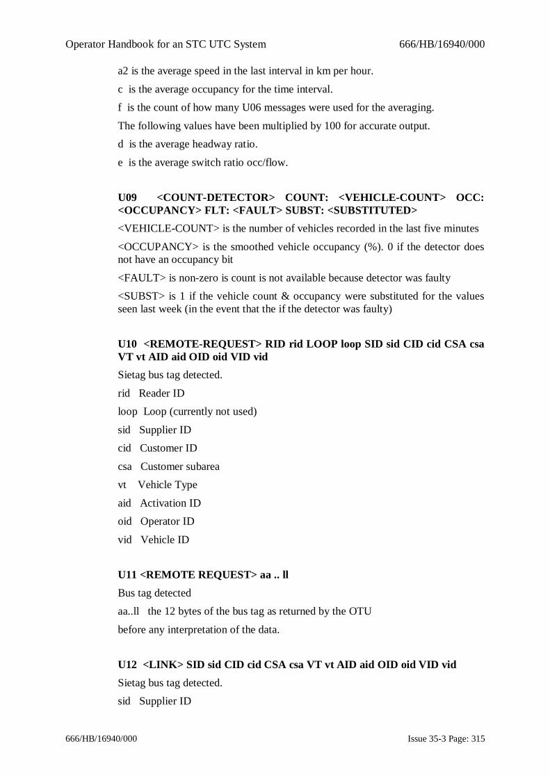
Operator Handbook for an STC UTC System 666/HB/16940/000
666/HB/16940/000 Issue 35-3 Page: 315
a2 is the average speed in the last interval in km per hour.
c is the average occupancy for the time interval.f is the count of how many U06 messages were used for the averaging.
The following values have been multiplied by 100 for accurate output.d is the average headway ratio.
e is the average switch ratio occ/flow.
U09 <COUNT-DETECTOR> COUNT: <VEHICLE-COUNT> OCC:<OCCUPANCY> FLT: <FAULT> SUBST: <SUBSTITUTED><VEHICLE-COUNT> is the number of vehicles recorded in the last five minutes
<OCCUPANCY> is the smoothed vehicle occupancy (%). 0 if the detector doesnot have an occupancy bit
<FAULT> is non-zero is count is not available because detector was faulty<SUBST> is 1 if the vehicle count & occupancy were substituted for the valuesseen last week (in the event that the if the detector was faulty)
U10 <REMOTE-REQUEST> RID rid LOOP loop SID sid CID cid CSA csaVT vt AID aid OID oid VID vidSietag bus tag detected.
rid Reader IDloop Loop (currently not used)
sid Supplier IDcid Customer ID
csa Customer subareavt Vehicle Type
aid Activation IDoid Operator ID
vid Vehicle ID
U11 <REMOTE REQUEST> aa .. llBus tag detectedaa..ll the 12 bytes of the bus tag as returned by the OTU
before any interpretation of the data.
U12 <LINK> SID sid CID cid CSA csa VT vt AID aid OID oid VID vidSietag bus tag detected.sid Supplier ID

Operator Handbook for an STC UTC System 666/HB/16940/000
666/HB/16940/000 Issue 35-3 Page: 316
cid Customer ID
csa Customer subareavt Vehicle Type
aid Activation IDoid Operator ID
vid Vehicle ID
U15 Link <LINK> Inc Started. ATGBV a ALOTPV b FREQ c RuleGp da is the average time gap between vehicles (*100)b is the average loop occupancy time per vehicle (*100)
c is the averaging frequency in intervals of 30 seconds.d is the rule group for this detector.
U16 Link <LINK> Inc Cleared. ATGBV a ALOTPV b FREQ c RuleGpda is the average time gap between vehicles (*100)b is the average loop occupancy time per vehicle (*100)
c is the averaging frequency in intervals of 30 seconds.d is the rule group for this detector.
U17 Link <LINK> Grp Inc Started. ATGBV a ALOTPV b FREQ cDetGp da is the average time gap between vehicles (*100)b is the average loop occupancy time per vehicle (*100)
c is the averaging frequency in intervals of 30 seconds.d is the detector group number.
U18 Link <LINK> Grp Inc Cleared. ATGBV a ALOTPV b FREQ cDetGp da is the average time gap between vehicles (*100)b is the average loop occupancy time per vehicle (*100)
c is the averaging frequency in intervals of 30 seconds.d is the detector group number.
U19 Link <LINK> Calib error: RuleGp:a ALOTPV:b MAX:c ATGBV:dMIN:ea: is the rule group for this detector.

Operator Handbook for an STC UTC System 666/HB/16940/000
666/HB/16940/000 Issue 35-3 Page: 317
b: is the average loop occupancy time per vehicle (*100).
c: is the Max ALOTPV from the rule data.d: is the average time gap between vehicles (*100).
e; is the Min ATGBV from the rule data.
U22 <Link> Trig=T Pri=P SD=SS VCC=CC Veh=VVVVV OK=KOutput when the TP bit triggers for a junction.
U22 <Link> Trig=T Pri=P SD=SS VCC=CC Veh=VVVVV OK=KThis message is output when the SCOOT system receives a RTIG bus notificationfor this link. The values displayed are provided by the AVL system (except forK).T Trigger Point (0 = Register, 1 = Request, 2 = Clear)
P Priority (1-3)SD Schedule Deviation (How late or early the bus is)
0: Schedule Not Supplied1: >=1 and <2 minutes late
2: >=2 and <3 minutes late3: >=3 and <5 minutes late
4: >=5 and <7 minutes late5: >=7 and <10 minutes late
6: >=10 and <15 minutes late7: >=15 minutes late
8: On time (within a minute)9: >=1 and <2 minutes early
10: >=2 and <3 minutes early11: >=3 and <5 minutes early
12: >=5 and <7 minutes early13: >=7 and <10 minutes early
14: >=10 and <15 minutes early15: >=15 minutes early
CC: Local Vehicle Control CentreVVVVV: The bus vehicle ID
K: If 0 then this bus detection is ignored. If 1 then it is supplied to SCOOT. Thebus will be ignored if the trigger point is 2 or if a journey time (BJNY, BJT2) hasnot been specified for the particular trigger point.

Operator Handbook for an STC UTC System 666/HB/16940/000
666/HB/16940/000 Issue 35-3 Page: 318
U26 <DETECTOR> MPH a1 KMPH a2 FLOW b OCC c HR d SR eDETL fa1: average speed in the last interval in miles per hour
a2: average speed in the last interval in km per hourb: flow by detector and time interval.
f: is the number of lanes covered by the detector as specified by the DETLparameter
The following values have been multiplied by 100 for accurate output:c: occupancy by detector and time interval.
d: the headway ratio.e: the switch ratio occ/flow.
U27 <Remote-Request> Pri=P SD=SS VCC=CC Veh=VVVVVThis message is output when the SCOOT system receives an RTIG busnotification for this remote request. The values displayed are provided by theAVL system and are provided for information only.
P Priority (1-3)SD Schedule Deviation (How late or early the bus is)
0: Schedule Not Supplied1: >=1 and <2 minutes late
2: >=2 and <3 minutes late3: >=3 and <5 minutes late
4: >=5 and <7 minutes late5: >=7 and <10 minutes late
6: >=10 and <15 minutes late
U28 <Link> KPH sssss Flow ccc Occ ooooo Faulty fThis message is output every minute and reports the estimated speed over theloop(s), the leading edge vehicle count, and the percentage occupancy for the oneperiod summed/averaged for all the detectors on the link.Sssss: Speed in kilometres/hour
Ccc: Leading edge vehicle countOoooo: Percentage occupancy
F: 1 if link is faulty, 0 otherwise
U80 <OUTSTATION> UTMC2 Stats - SNMP Message Summary.Sets/Gets:PP Resp:RR Timeouts:TT Peformance:%%SNMP message summary for UTMC Type 2 OTUs every 5 minutes.

Operator Handbook for an STC UTC System 666/HB/16940/000
666/HB/16940/000 Issue 35-3 Page: 319
PP: the total number of SNMP SET and GET messages
RR: the total number of SNMP responses receivedTT: the total number of requests that timed-out
%%: RR/PP expressed as a percentage.
U81 <OUTSTATION> UTMC2 Stats - SNMP Message Response. Ave:AAAms Best: BBBms Worst: CCCmsReport UTMC2 Mark 2 communications response times - that is, the time taken tosend an SNMP request and receive a response back from the OTU for it. This isoutput every five minutes. All times are in milliseconds. Only successful requestscan be timed. For requests that timed-out see the U80 message.AAA: average (mean) response time of all requests in 5 min period.
BBB: best response time seen in 5 minute period
WWW: worst response time seen in 5 minute period.U82 <OUTSTATION>UTMC2 Stats - SNMP Message Delivery Performance: %% SNMP Messagelongest blackout: BBBs. Reconnects: RRRSummary report output every five minutes.%%: Percentage of SNMP requests successfully delivered (weighted in favour ofSET requests).BBB: Longest interval in seconds during which communications timed-out
RRR: The number of times the instation has had to restart communications to theOTU
U83 <OUTSTATION> UTMC2 Stats - SNMP Inform Summary. Count:CCCReply lag(s):Ave:AAA Best:BBB Worst:WWW Performance:%%Summary report output every five minutes focusing on SNMP inform messagereceived from the OTU. Inform messages contain OTU reply data. The delay timeof such messages can only be estimated to within 1-2 seconds so these values areof limited usefulness.
CCC: Number of inform messages receivedAAA: average estimated transmission delay
BBB: best estimated transmission delayWWW: worst estimated transmission delay
%%: percentage of messages that took <= 1 second to deliver

Operator Handbook for an STC UTC System 666/HB/16940/000
666/HB/16940/000 Issue 35-3 Page: 320
12. System Interfaces
12.1 IntroductionThe UTC System is capable of interfacing to a variety of other systems thatsupply or receive traffic information. The following sections describe the currentinterfaces supported.
12.2 Interface to ASTRIDThe UTC System provides an interface to an ASTRID System, which enablesUTC data to be transferred for further processing and calculation by ASTRID.The parameters transferred are:
Event messages - congestion data, as required.Daily file transfers:
car park occupanciescar park weighted averages
car park occupancy predictions.
12.3 Interface to ARTEMISThe UTC System is able to interface to an ARTEMIS system taking ARTEMISdetector data for use with other count and occupancy detectors. ARTEMIS datacan be used in displays as for other detectors.
The data is sent to the UTC System at 1(B) minute intervals. Since ARTEMISdoes not use OTUs for transmission of the data, the detectors can be configured inthe database without OTU data. Displays such as OVRB and MONI that showOTU control and reply bytes are therefore not appropriate for use with ARTEMISdetectors.Invalid or suspect data is highlighted in the same manner as for other data.
12.4 Interface for Collection of On Street Parking dataThe UTC System is able to interface to an On Street Parking PC that collects datafrom Pay and Display type machines on current ticket validity. The data isreceived from the PC every 15 minutes.Up to 30 on street ticket machines can be configured together to form each type 5,on street car park. Each ticket machine has its own 4-character identity and canonly be configured into one car park at a time.
Commands for other car park types, setting states, capacities and thresholds anddisplaying occupancies, weighted averages and predictions, can be used with OnStreet car parks. Since OTUs are not used for data transmission, displays such asOVRB and MONI are not appropriate.

Operator Handbook for an STC UTC System 666/HB/16940/000
666/HB/16940/000 Issue 35-3 Page: 321
The car park occupancy can be adjusted to allow for over or under buying oftickets using VALU/CHAN parameter. PDCC, range 1-200. The occupancy iscalculated by the following formula:
Occupancy Number of Valid Tickets * PDCC100
=
If the connection to the PC is lost, the car park occupancy is derived from theweighted average data stored for the car park.
12.5 Interface to the Remote Monitoring SystemThe UTC System is able to accept fault data from the STC RMS. The data isprocessed with other UTC fault data. Count data is also accepted from the RMSand may be displayed with other count data.
12.6 Interface to UTMC Compliant DatabaseThe UTC System is able to send data to a UTMC compliant Database server suchas COMET. The data is sent automatically.
The UTC also receives commands from the UTMC compliant Database serverwhich are actioned in the same manner as commands input by the operator.
12.7 Interface to Variable Message Sign Control PCThe UTC System is able to send car park and spaces data to a VCS PC for displayon variable message signs. VCS controlled signs may be configured in thedatabase.A number of car parks may be grouped together to enable spaces data for thegroup to be displayed on one sign. The determination of car park group states is asfor existing car park groups on named type car park signs. Capacity andoccupancy values of car park groups are summed from the values for each opencar park within the group.
Car park occupancy prediction data may be used in conjunction with the journeytime from the sign to the car park to provide a more accurate spaces value. Theadditional data is used to adjust the spaces value to the number of spaces predictedto be left at the time of arrival at the car park. This is of value at busy times whenthe journey time may be significantly greater. The journey time can be configuredusing the VALU/CHAN parameter CJNY.
The VCS PC returns sign status data for inclusion in the UTC System log.

Operator Handbook for an STC UTC System 666/HB/16940/000
666/HB/16940/000 Issue 35-3 Page: 322
12.8 Interface to Motorway Control SystemThe UTC System is able to accept commands to action CASTS from the NMCS.Having actioned the CAST, the UTC System returns to the NMCS a message andthe number of the command introduced by the CAST. The relevant operatorcommand is NMCS.
12.9 Interface to Environmental SensorsThe UTC has the ability to interface to environmental analogue sensors forcollecting and storing pollution and other environmental data, and to implementcontrol strategies when one or a number of these sensors exceeds user definedthreshold levels.

Operator Handbook for an STC UTC System 666/HB/16940/000
666/HB/16940/000 Issue 35-3 Page: 323
Appendix A - Summary of System CommandsThis is a table of all the commands available in the UTC System. Against eachcommand there are a number of parameters, which are:L - the default command level required to action it
O - operator commandT - timetable command
G - command is loggedA - actioned in real time. A command of this type, when occurring in a
timetable, is only actioned at the defined time. If the system is restarted andthe timetable scanned, these commands are not actioned if this time haspassed.
C - can be used in a CAST
J - command is journalledType
Name Function L O T G A C J
ACAS Action CAST 8 O T GACCT Action CAST by region cycle time 13 O T G C
ACKD Acknowledge fault(s) and cancel alarm 2 O GACSV Action CASTs by Sensor Values 8 O T G C
ALRM Output alarm text message 10 O T CARCM Start removable Disk Archive 14 O G
ARRQ Associate remote request with CASTs 13 O T G CASCC Action CAST by Saturation/Congestion 13 O T G C
ASLD Assign SCOOT link to count detector 12 OASTD Start up the ASTRID display 14 O
AUDI Enable audible alarms 8 O T G C JAUTH Change SCOOT Authorities 13 O G
AVSP Average SCOOT Plans 4 O T G A CCANA Silence audible alarms 1 O G
CARP Change Car Park status 12 O T G C JCDBC Select SCNs to be sent to Common Data Base 14 O
CHAN Change value of parameter 8 O T G C JCHCK Start controller test sequence checking 12 O T G A C
CHCP Change pelican controller checks mode 16 T G C JCHDC Initiate SCOOT detector counts checking 16 T A CCHGO Changeover to standby computer 16 O T A C
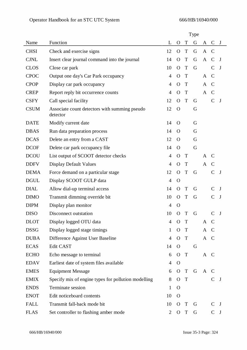
Operator Handbook for an STC UTC System 666/HB/16940/000
666/HB/16940/000 Issue 35-3 Page: 324
Type
Name Function L O T G A C J
CHSI Check and exercise signs 12 O T G A CCJNL Insert clear journal command into the journal 14 O T G A C J
CLOS Close car park 10 O T G C JCPOC Output one day's Car Park occupancy 4 O T A C
CPOP Display car park occupancy 4 O T A CCREP Report reply bit occurrence counts 4 O T A C
CSFY Call special facility 12 O T G C JCSUM Associate count detectors with summing pseudo
detector12 O G
DATE Modify current date 14 O G
DBAS Run data preparation process 14 O GDCAS Delete an entry from a CAST 12 O G
DCOF Delete car park occupancy file 14 O GDCOU List output of SCOOT detector checks 4 O T A C
DDFV Display Default Values 4 O T A CDEMA Force demand on a particular stage 12 O T G C JDGUL Display SCOOT GULP data 4 O
DIAL Allow dial-up terminal access 14 O T G C JDIMO Transmit dimming override bit 10 O T G C J
DIPM Display plan monitor 4 ODISO Disconnect outstation 10 O T G C J
DLOT Display logged OTU data 4 O T A CDSSG Display logged stage timings 1 O T A C
DUBA Difference Against User Baseline 4 O T A CECAS Edit CAST 14 O G
ECHO Echo message to terminal 6 O T A CEDAV Earliest date of system files available 4 O
EMES Equipment Message 6 O T G A CEMIX Specify mix of engine types for pollution modelling 8 O T C J
ENDS Terminate session 1 OENOT Edit noticeboard contents 10 O
FALL Transmit fall-back mode bit 10 O T G C JFLAS Set controller to flashing amber mode 2 O T G C J

Operator Handbook for an STC UTC System 666/HB/16940/000
666/HB/16940/000 Issue 35-3 Page: 325
Type
Name Function L O T G A C J
FLOW Display detector flow monitor 4 OFLTA Specify which faults should raise a system alarm 12 O T C J
FLTG Create or modify a fault group 6 O GFLTY Set fault manually 12 O T G A C
GDDD Graphical data display 1 OGENP Generate semi-graphic pictures 6 O
GUBA Restore recorded baseline values 10 O T G C JGWAV Start operator green wave 12 O G
HELP Online HELP screen 1 OHRYC Start manual hurry call 12 O T G A C
ICAS Insert an entry into a CAST 12 O GIFLT Inhibit faults by category on an equipment 10 O T G C J
IHPC Inhibit plan compliance fault isolation 12 O T G C JIHRW Inhibit reply word analysis 12 O T G C J
IHTP Inhibit tram priority 12 O T G C JINFO Display information for an outstation 4 OINHW Inhibit weekly flow analysis 10 O T C
INTD Introduce diversion 10 O T G C JISOL Isolate controller 10 O T G C J
KILL Shutdown System 12 O GLACC List CAST associations 4 O T A C
LACS List configured ACSV commands 4 O T A CLARR List Associated Remote Requests 4 O T A C
LASC List CASTs actioned by Saturation/Congestion 4 O T A CLCAS List the contents of a CAST 4 O T A C
LCOF List car park occupancy files 4 O GLEME List equipment messages created by EMES 4 O T A C
LFLG List currently defined fault groups 4 O T A CLFTA List faults which raise system alarms 4 O T A C
LIFT List categories of faults that have been inhibited 4 O T A CLIHR List equipments with reply word analysis inhibited 4 O T A C
LIHS List controller history 4 O T A CLIPT List plan timings 4 O T A C
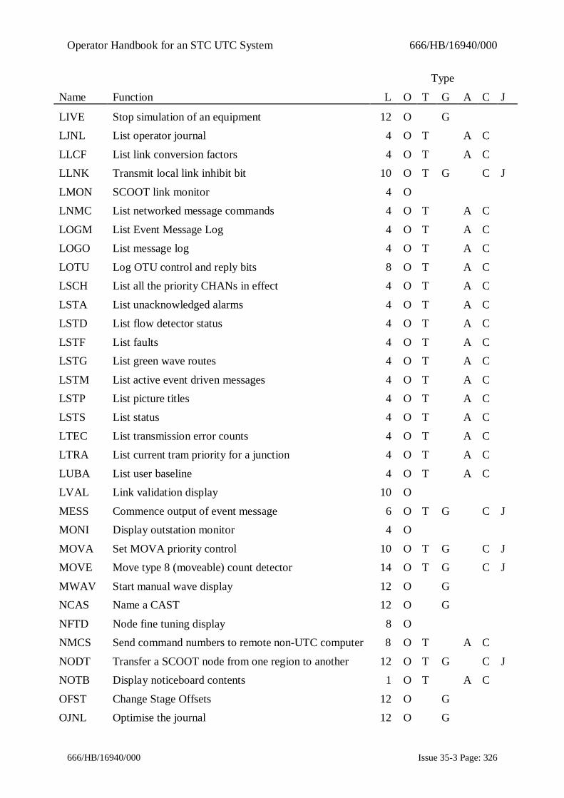
Operator Handbook for an STC UTC System 666/HB/16940/000
666/HB/16940/000 Issue 35-3 Page: 326
Type
Name Function L O T G A C J
LIVE Stop simulation of an equipment 12 O GLJNL List operator journal 4 O T A C
LLCF List link conversion factors 4 O T A CLLNK Transmit local link inhibit bit 10 O T G C J
LMON SCOOT link monitor 4 OLNMC List networked message commands 4 O T A C
LOGM List Event Message Log 4 O T A CLOGO List message log 4 O T A C
LOTU Log OTU control and reply bits 8 O T A CLSCH List all the priority CHANs in effect 4 O T A C
LSTA List unacknowledged alarms 4 O T A CLSTD List flow detector status 4 O T A C
LSTF List faults 4 O T A CLSTG List green wave routes 4 O T A C
LSTM List active event driven messages 4 O T A CLSTP List picture titles 4 O T A CLSTS List status 4 O T A C
LTEC List transmission error counts 4 O T A CLTRA List current tram priority for a junction 4 O T A C
LUBA List user baseline 4 O T A CLVAL Link validation display 10 O
MESS Commence output of event message 6 O T G C JMONI Display outstation monitor 4 O
MOVA Set MOVA priority control 10 O T G C JMOVE Move type 8 (moveable) count detector 14 O T G C J
MWAV Start manual wave display 12 O GNCAS Name a CAST 12 O G
NFTD Node fine tuning display 8 ONMCS Send command numbers to remote non-UTC computer 8 O T A C
NODT Transfer a SCOOT node from one region to another 12 O T G C JNOTB Display noticeboard contents 1 O T A C
OFST Change Stage Offsets 12 O GOJNL Optimise the journal 12 O G

Operator Handbook for an STC UTC System 666/HB/16940/000
666/HB/16940/000 Issue 35-3 Page: 327
Type
Name Function L O T G A C J
OPEN Open car park 10 O T G C JOPFD Output flow detector data 4 O T A C
OUTT List contents of timetable 4 OOVRB Override control/reply bits 15 O G
PICT Display selected picture 4 OPLAN Select fixed-time plan 8 O T G C J
PPRP Prepare plan data 14 OPRIN Enable log printer 10 O T G C J
PVAL Print LVAL log 4 O GRCOF Record car park occupancy file 14 O G
REIN Reinitialise SCOOT databases 14 O T G A C JREMD Remove diversion 10 O T G C J
RFTD Region fine tuning display 8 ORRUL Select Raid rules file 10 O T G C J
RSTA Shut down and restart UTC computer 16 O GRUBA Record user baseline 10 O GSAPS Start automatic plan selection 10 O T G C J
SCAS Action the CHANs in a CAST in priority mode 8 O GSCOO Implement SCOOT control 8 O T G C J
SEED Look at database values 4 OSFNO Inhibit special facility selection 12 O T G C J
SIGN Override sign legend 12 O T G C JSIGO Change Car Park sign group search order 12 O T G C J
SLOF Turn part time signals off 12 O T G C JSNSD Display current analogue sensor value 4 O
SNSS Display analogue sensor value 4 OSNSV Display current sensor value 4 O T A C
SORT Sort controller checks messages 8 O T A CSSGM Log stage timings to data file 1 O T G A C
SSPC Send message to SIESPACE Car Park PC 12 O T A CSSSU Start SCOOT survey 10 O T
STCS List car park/sign status 4 O T A CSURV Display survey flow counts 4 O
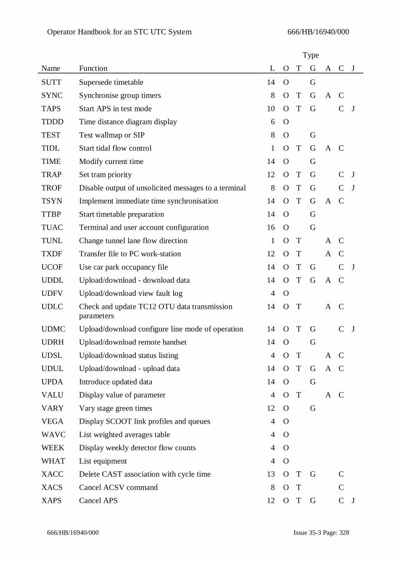
Operator Handbook for an STC UTC System 666/HB/16940/000
666/HB/16940/000 Issue 35-3 Page: 328
Type
Name Function L O T G A C J
SUTT Supersede timetable 14 O GSYNC Synchronise group timers 8 O T G A C
TAPS Start APS in test mode 10 O T G C JTDDD Time distance diagram display 6 O
TEST Test wallmap or SIP 8 O GTIDL Start tidal flow control 1 O T G A C
TIME Modify current time 14 O GTRAP Set tram priority 12 O T G C J
TROF Disable output of unsolicited messages to a terminal 8 O T G C JTSYN Implement immediate time synchronisation 14 O T G A C
TTBP Start timetable preparation 14 O GTUAC Terminal and user account configuration 16 O G
TUNL Change tunnel lane flow direction 1 O T A CTXDF Transfer file to PC work-station 12 O T A C
UCOF Use car park occupancy file 14 O T G C JUDDL Upload/download - download data 14 O T G A CUDFV Upload/download view fault log 4 O
UDLC Check and update TC12 OTU data transmissionparameters
14 O T A C
UDMC Upload/download configure line mode of operation 14 O T G C JUDRH Upload/download remote handset 14 O G
UDSL Upload/download status listing 4 O T A CUDUL Upload/download - upload data 14 O T G A C
UPDA Introduce updated data 14 O GVALU Display value of parameter 4 O T A C
VARY Vary stage green times 12 O GVEGA Display SCOOT link profiles and queues 4 O
WAVC List weighted averages table 4 OWEEK Display weekly detector flow counts 4 O
WHAT List equipment 4 OXACC Delete CAST association with cycle time 13 O T G C
XACS Cancel ACSV command 8 O T CXAPS Cancel APS 12 O T G C J

Operator Handbook for an STC UTC System 666/HB/16940/000
666/HB/16940/000 Issue 35-3 Page: 329
Type
Name Function L O T G A C J
XARR Disassociate remote request and CASTs 13 O T CXASC Cancel Action CAST by Saturation/Congestion 13 O T C
XAUD Disable audible alarms 8 O T G C JXCAR Cancel car park state control 12 O T G C J
XCHA Cancel a priority CHAN command 8 OXCHC Stop controller test sequence checking 12 O T G A C
XCHG Restore normal TCC operation 16 O T A CXCHS Stop sign exercising 12 O T G A C
XCSF De-select special facility 12 O T G C JXDEM Cancel forced demand(s) on a particular stage 12 O T G C J
XDIA Disable dial up access 14 O T G C JXDIM Clear dimming override bit 10 O T G C J
XDIS Re-connect outstation 10 O T G C JXEME Clear equipment message 6 O T G A C
XFAL Clear fall-back mode bit 10 O T G C JXFLA Cancel flashing amber mode 2 O T G C JXFLG Delete a fault group 6 O G
XFLT Clear fault 8 O T G A CXFTA Specify faults which should not raise system alarms 12 O T C J
XGWA Cancel operator green wave 12 O GXHRY Cancel manual hurry call 12 O T G A C
XIFT Cancel inhibition of fault categories on equipments 10 O T G C JXIHP Re-enable plan compliance fault isolation 12 O T G C J
XIHR Re-enable reply word analysis 12 O T G C JXIHT Cancel inhibition of tram priority 12 O T G C J
XINH Cancel inhibition of weekly flow analysis 10 O T CXISO Cancel controller isolation 10 O T G C J
XLIV Start simulation of an equipment 12 O GXLLN Clear local link inhibit bit 10 O T G C J
XLOT Cancel logging of OTU control & reply bits 8 O T A CXMES Stop output of event message 6 O T G C J
XMOV Remove type 8 (moveable) count detector from anOTU
14 O T G C J

Operator Handbook for an STC UTC System 666/HB/16940/000
666/HB/16940/000 Issue 35-3 Page: 330
Type
Name Function L O T G A C J
XMVA Cancel MOVA control mode 10 O T G C JXPLA Cancel operator fixed-time plan 8 O T G A C J
XPRI Disable log printer 10 O T G C JXRUB Delete data previously entered by RUBA command 14 O G
XSCA Action the CHANs in a selected CAST in CancelCHAN Priority mode
8 O
XSCO Cancel SCOOT control 8 O T G C JXSFN Re-enable special facility selection 12 O T G C J
XSIG Cancel sign legend override 12 O T G C JXSLO Turn part-time signals on 12 O T G C J
XSPO Cancel spooled output 4 OXSSG Cancel logging of stage timings data 1 O T G A C
XSUT Cancel operator timetable 14 O GXTAP Cancel APS in test mode 10 O T G C J
XTES Cancel wallmap or SIP lamp test 8 O GXTID Cancel tidal flow scheme 1 O T G A CXTRA Clear tram priority for a junction 12 O T G C J
XTRO Enable output to a terminal 8 O T G C JXTTC Remove command from temporary time table 8 O
XTUN Cancel tunnel control 1 O T G A C

Operator Handbook for an STC UTC System 666/HB/16940/000
666/HB/16940/000 Issue 35-3 Page: 331
Appendix B - Fault and Advice DetailsThe following table defines the fault messages and categories which shall be detected andreported by the UTC System. Where a fault shall cause the equipment to be isolated (I) this isindicated, as is the nature of the alarm - System (S) or Operational (O). The reporting of thosefaults marked H may be inhibited by use of the (licenceable) IFLT command
Cat Fault Message TypeI S O H
100 Controller faults110 Controller monitoring111 Signals stuck in intergreen I S H112 Signals stuck on stage I S H113 Signals stuck on minimum I S H114 Invalid stage transition (for junctions) I S H114 No vehicle green confirm (for pelicans) I S H115 Permanent stage demand I S H116 Permanent intergreen extension I S H117 Multiple green confirm bits I S H120 Plan compliance121 Plan compliance fault I S122 Stage forced, different stage returned (for junctions) I S H122 Pedestrian demand not serviced (for pelicans) S H123 Demand dependent stage fault S H130 Lamps/fixed-time/manual S131 Lamps off I S132 Manual control in operation I S H133 Remote attended I S H134 Fixed time I S H135 CLF S H136 Pelican signals off I S H137 No break battery failing S H138 Cabinet door open S H140 Miscellaneous141 Type 141 controller fault S H142 Emergency vehicle fault S H143 Invalid phase pattern S H144 Fall-back mode compliance fault S145 Emergency vehicle detected I S H146 Hurry call detected I S H147 Hurry call fault S H148 Pedestrian Confirm/Vehicle Green (PC/GX) reply conflict S H149 Lamp failure. Pedestrian stage inhibited S H150 Flashing mode151 Flashing mode fault S H160 Controller synchronisation161 Controller sync fault S H162 Group timer sync failed S H163 Wrong day of week S H

Operator Handbook for an STC UTC System 666/HB/16940/000
666/HB/16940/000 Issue 35-3 Page: 332
Cat Fault Message TypeI S O H
164 Invalid day of week S H165 CS bit stuck S H170 Tidal flow controllers171 Control confirmation fault S H172 Unexpected aspect reply change S173 Invalid aspect transition S174 Not responding to force bits S175 Inter-aspect fault S176 Stuck on inter-aspect S177 Stuck on aspect S178 XX aspect not seen S180 Tidal flow controllers181 Aspect minimum violation S H182 Urgent fault reported S H183 Minor fault reported S H184 Power fail S H185 Invalid aspect reply S187 RTC Synchronisation fault S188 Emergency close not confirmed S190 LRT controllers191 LRT controller surge protection unit status S192 LRT artificial request status S193 LRT detector fault S194 LRT OTU status S

Operator Handbook for an STC UTC System 666/HB/16940/000
666/HB/16940/000 Issue 35-3 Page: 333
Cat Fault Message TypeI S O H
200 Controller timings faults210 Intersection timing faults211 Minimum green fault S H212 Maximum green fault S H213 Intergreen fault S H214 Extension violation S H220 Pelican timing faults221 Min green to vehicles fault S H222 Min non green to vehicles fault S H223 Max non green to vehicles fault S H224 Extension violation S H226 Flashing amber freq. fault S H227 Min pedestrian confirm fault S H228 Max pedestrian confirm fault S H

Operator Handbook for an STC UTC System 666/HB/16940/000
666/HB/16940/000 Issue 35-3 Page: 334
Cat Fault Message TypeI S O H
300 Lamp faults310 Intersection lamp faults311 Identified lamp fault S H312 Identified red lamp fault S H312 Red to vehicle lamp fault (pelican) S H313 Two or more 3 aspect lamp faults S H314 Unidentified lamp fault S H315 Lamp Failure identified by RMLU S H330 Solar lamp faults331 Lamp fuse failed S H332 Lamp not dimming fault S H333 Lamp always dim fault S H334 Solar bright fault S335 Part time signals fault, signals on despite turned off by SL bit S

Operator Handbook for an STC UTC System 666/HB/16940/000
666/HB/16940/000 Issue 35-3 Page: 335
Cat Fault Message TypeI S O H
400 Ancillary OSN equipment410 VA detector411 VA detector fault S H412 SD detector fault H413 Permanent SD demand fault H420 SCOOT detector421 SCOOT detector fault - full S422 SCOOT detector fault - empty S423 SCOOT detector fault - OTU fault S424 SCOOT detector fault – data persistently late/missing S430 Counting detector431 Counting detector fault S H432 No counts for last 15 minutes S H440 Car park interface441 Car park barrier fault S442 Car park using detector fault S443 Car park state fault S444 Car park vehicle count exceeds capacity S445 Car park vehicle count negative S446 Invalid barrier vehicle count S447 Suspect change of barrier count S448 No change of vehicle count for hours S450 Variable message sign451 Sign legend not confirmed I S452 Sign invalid reply state I S453 Sign in manual mode I S454 Sign lamp failure S455 Sign PC link failure S456 Sign isolated457 Sign fault (SieSpace)458 Sign communication fault (SieSpace)460 Pelican push buttons461 Push button fault S H462 No pedestrian demand S H463 Permanent pedestrian demand S H464 Permanent pedestrian stage max extension detected S H470 Queue detector471 Queue detector fault S H472 Analogue sensors472 Analogue sensor fault S473 No sensor data for 5 minutes S474 Sensor level high S475 Sensor level low S476 Sensor OTU fault S477 Sensor under manual calibration S478 Sensor performing own zero check S479 Sensor status channel not healthy S480 Diversion signs

Operator Handbook for an STC UTC System 666/HB/16940/000
666/HB/16940/000 Issue 35-3 Page: 336
Cat Fault Message TypeI S O H
481 Diversion sign invalid reply state S H482 Diversion sign in manual mode S483 Sign power failure S H484 Sign fault (SieSpace)485 Sign communication fault (SieSpace)490 Special facilities491 Special facility sign invalid reply state I S H492 Special facility sign in manual mode I S H

Operator Handbook for an STC UTC System 666/HB/16940/000
666/HB/16940/000 Issue 35-3 Page: 337
Cat Fault Message TypeI S O H
500 Transmission system510 No response from OTU511 TX fault, no reply for several seconds I S512 Persistent TX fault I S H513 Intermittent TX fault I S H514 Configuration mismatch S515 Unit has wrong time S516 Initialisation error S517 Not responding S518 Protocol error S519 Unable to resolve IP address S520 Instation data TX faults521 Outstation output stuck I S522 Outstation isolated by PC fault523 Isolated – line in use by upload/download524 Outstation disconnected by operator525 Offline S526 Timed-out waiting for key-frame S530 Instation Telecommand 12 PC faults531 PC disconnected I S532 Intermittent fault I S H533 Persistent fault I S H534 Configuration fault I S

Operator Handbook for an STC UTC System 666/HB/16940/000
666/HB/16940/000 Issue 35-3 Page: 338
Cat Fault Message TypeI S O H
600 Instation equipment610 Processor611 Checkword fault I S612 Clocks unsynchronised S613 CPU arithmetic error I S620 Discs621 System disc not available S622 Data disc not available S630 Inter-processor links631 Non-urgent data mismatch fault S640 Terminals641 Output timed out S642 Failed to respond S643 Terminal queue time-out S644 Slow device/message rate too high – messages lost I650 External command interfaces651 Invalid command received S652 Losing commands S

Operator Handbook for an STC UTC System 666/HB/16940/000
666/HB/16940/000 Issue 35-3 Page: 339
Cat Fault Message TypeI S O H
700 OMU Faults (RMS link to UTC)711 OMU power failed S721 Vehicle phase lamp fail S722 Pedestrian phase lamp fail S723 Green arrow lamp fail S724 Wait lamp fail S725 Regulatory signs fail S726 Switched signs bulb fail S727 Pedestrian flash fail S728 Dim/bright fail S729 Vehicle presence fail S731 Vehicle absence fail S732 Lamps off S733 Lamps flashing S734 Controller stuck S735 Controller ignoring demands S736 Short stage minimum green S737 Short phase intergreen S738 Long all red S739 Short stage ext/max S741 Long stage max S742 Long alternative max S743 Long stage extension S744 Conflicting phase green S745 External input active S746 Stage sequencing fault S747 Long interstage period S748 T200/T400/ST800 fault log entry S749 GEC3000 fault log entry S751 Ferranti TSC fault log entry S

Operator Handbook for an STC UTC System 666/HB/16940/000
666/HB/16940/000 Issue 35-3 Page: 340
Cat Fault Message TypeI S O H
800 Ancillary outstation equipment810 Remote Requests811 Permanent remote request S H820 MOVA Control821 MOVA not confirmed S H822 MOVA offline S H823 MOVA fault S H824 MOVA enabled locally S H

Operator Handbook for an STC UTC System 666/HB/16940/000
666/HB/16940/000 Issue 35-3 Page: 341
Cat Fault Message TypeI S O P H
900 NMCS Equipment911 Unobtainable S 1 H912 Power fail S 1 H913 Set not confirmed S 1 H914 Single bulb fail S 3 H915 Dual bulb fail S 1 H921 Aspect xxxx fail (See note 1 below) * H922 Red flasher fail S 1 H923 Mains fail S 1 H924 Dimmer failed S 3 H925 Amber flasher failed S 2 H926 Flasher sync failed S 1 H927 Aspect undefined S 1 H928 Isolated S 1 H931 Printer S 1 H932 Operational problem S 3 H933 WORM drive S 3 H934 Disk 1 S 3 H935 Disk 2 S 3 H936 HP disk S 3 H937 Motorola disk S 3 H938 External clock S 3 H939 Mains failed S 1 H941 Program failure S 1 H942 Self test failed S 1 H943 Site data failed S 1 H944 Fan failure S 2 H945 Line hogging S 1 H946 Operator problem S 3 H947 Battery charger fault S 1 H948 Stepper fault S 1 H949 Contraflow S 3 H951 PLC fault S 1952 Manual mode S 3
The above faults all generate System Alarms but are categorised at different fault priorities,which is indicated by the number in the last column. If used in graphics, faults in priority 1cause a Red border to be shown, in priority 2 they result in a Magenta border and in priority 3a yellow border.Note 1 :- The string "xxxx" identifies the aspect failing, and can be any of the validaspects. The aspects strings normally encountered are listed below and these failures areassigned to fault priority 1. Other aspect faults are assigned to fault priority 3.
NULL, END, RE STOP, 20, 30 , 40, 50, 60, 70, LDR, X, LDL, MDL, IT, TI, 1(C) [arrow],MDR, FOG, Q and AMB.
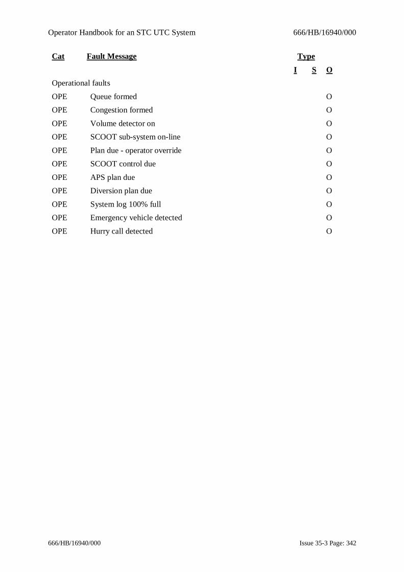
Operator Handbook for an STC UTC System 666/HB/16940/000
666/HB/16940/000 Issue 35-3 Page: 342
Cat Fault Message Type
I S OOperational faults
OPE Queue formed OOPE Congestion formed O
OPE Volume detector on OOPE SCOOT sub-system on-line O
OPE Plan due - operator override OOPE SCOOT control due O
OPE APS plan due OOPE Diversion plan due O
OPE System log 100% full OOPE Emergency vehicle detected O
OPE Hurry call detected O
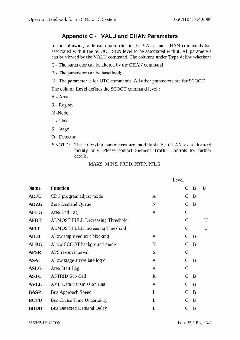
Operator Handbook for an STC UTC System 666/HB/16940/000
666/HB/16940/000 Issue 35-3 Page: 343
Appendix C - VALU and CHAN ParametersIn the following table each parameter to the VALU and CHAN commands hasassociated with it the SCOOT SCN level to be associated with it. All parameterscan be viewed by the VALU command. The columns under Type define whether :C - The parameter can be altered by the CHAN command;
B - The parameter can be baselined;U - The parameter is for UTC commands. All other parameters are for SCOOT.
The column Level defines the SCOOT command level :A - Area
R - RegionN -Node
L - LinkS - StageD - Detector
* NOTE : The following parameters are modifiable by CHAN as a licensedfacility only. Please contact Siemens Traffic Controls for furtherdetails.
MAXS, MINS, PRTD, PRTP, PFLG
Level
Name Function C B U
ADJU CDC program adjust mode A C B
ADZG Zero Demand Queue N C B
AELG Area End Lag A C
AFDT ALMOST FULL Decreasing Threshold C U
AFIT ALMOST FULL Increasing Threshold C U
AIEB Allow improved exit blocking A C B
ALBG Allow SCOOT background mode N C B
APSR APS re-run interval S C
ASAL Allow stage arrive late logic A C B
ASLG Area Start Lag A C
ASTC ASTRID Sub Cell R C B
AVLL AVL Data transmission Lag A C B
BASP Bus Approach Speed L C B
BCTU Bus Cruise Time Uncertainty L C B
BDDD Bus Detected Demand Delay L C B

Operator Handbook for an STC UTC System 666/HB/16940/000
666/HB/16940/000 Issue 35-3 Page: 344
Level
Name Function C B U
BDOL Bus distance optimisation limit L C B
BERL Bus Priority Extension/Recall Strategy N C B
BES0 Bus Link Extension Saturation (Importance 0) L C B
BES1 Bus Link Extension Saturation (Importance 1) L C B
BES2 Bus Link Extension Saturation (Importance 2) L C B
BES3 Bus Link Extension Saturation (Importance 3) L C B
BES4 Bus Link Extension Saturation (Importance 4) L C B
BES5 Bus Link Extension Saturation (Importance 5) L C B
BES6 Bus Link Extension Saturation (Importance 6) L C B
BEXR Bus Extension Recovery : N C B
BIAS Offset Bias L C B
BJNY Bus Journey time from detector L C B
BJT2 Bus Journey Time from Second Trigger Point L C B
BLAT Bus Late Limit L C B
BLCD Bus link has cancel detection L C B
BLNK Bottleneck Link L C
BLSD Bus link has secondary detection L C B
BOFF Bus Priority Status A C B
BOTT Bus On Time Threshold L C B
BPAN Bus Priority At Node N C B
BPER Bus Period A C B
BPFL Bus Priority Flag L C B
BRER Bus Recall Recovery : N C B
BRS0 Bus Link Recall Saturation (Importance 0) L C B
BRS1 Bus Link Recall Saturation (Importance 1) L C B
BRS2 Bus Link Recall Saturation (Importance 2) L C B
BRS3 Bus Link Recall Saturation (Importance 3) L C B
BRS4 Bus Link Recall Saturation (Importance 4) L C B
BRS5 Bus Link Recall Saturation (Importance 5) L C B
BRS6 Bus Link Recall Saturation (Importance 6) L C B
BSEL Bus Priority Selection Strategy : N C B
BSLT Bus Slightly Late Limit L C B
BTSM Bus Traffic Signal Movement L C B

Operator Handbook for an STC UTC System 666/HB/16940/000
666/HB/16940/000 Issue 35-3 Page: 345
Level
Name Function C B U
BTSN Bus Traffic Signal Number L C B
BVLT Bus Very Late Limit L C B
CACP Congestion Alarm Clear Percentage C U
CAPA Capacity C U
CASP Congestion Alarm Set Threshold C U
CDEF Calculated Default Stage Length S
CDSL Calculate Default Stage Lengths Status A C
CFBI Cycle Feedback Inhibit N C B
CGIF Congestion Importance Factor L C B
CGOF Congestion Offset Factor L C B
CGWT Congestion Weighting L C B
CHDI Cycle Time Historic Data Inhibit L C B
CJNY VMS to car park journey time C U
CLAM Cycle Lambda Factor A C B
CLAS Link Class L C B
CLIF Congestion Link Importance Factor L C B
CLNK Congestion Link L C
CLUS Cluster of Trigger Link L C B
CLWT Congestion Link Weighting Factor L C B
CMJI Cycle Time Minimum Jump Inhibit R C B
COMM Override Communication Profile U
COMP Composite Link L C B
CONN Configured Number of Nodes A
COPS Car park occupancy smoothing factor C U
CQT1 Queueing Time (Range 1) C U
CQT2 Queueing Time (Range 2) C U
CQT3 Queueing Time (Range 3) C U
CQT4 Queueing Time (Range 4) C U
CTFP Cycle Time Forward Period R C B
CTOI Cycle Time Optimisation Interval R C B
CYFX Cyclic Fixed Time N C
CYOS Cycle Time Optimizer Status R C
DAVL Discard AVL data L C B

Operator Handbook for an STC UTC System 666/HB/16940/000
666/HB/16940/000 Issue 35-3 Page: 346
Level
Name Function C B U
DCIG Double Cycle Ignore N C B
DDFL Demand Dependent Stage Optimisation S C B
DEFS Default Stage Length S C
DETL Number of lanes D C B
DETU Detector Used Status D C B
DFOF Default Offset L C B
DFSP Default Speed L C B
DGRN Double Green L
DIVR Diversion Re-run Interval A C B
DSTS Detector Status D C
DUDD Faulty Detectors D
ELAG End Lag L C B
ETHR Detector Empty Fault Threshold A C B
EXTD Bus Priority Extend Current Duration L C B
FCYT Forced Cycle Time R C
FDTH FULL Decreasing Threshold C U
FDWN Fast Downward Cycle Times Mode R C B
FITH FULL Increasing Threshold C U
FLEN Full Link Length L C B
FLST Filter Lower Saturation N C B
FMUL Filter Weighing Multiplier L C B
FORC Force Single/Double Cycling N C
FSAT Filter Weighing Saturation L C B
FTHR Detector Full Fault Threshold A C B
FUST Filter Upper Saturation N C B
GCAT Gating Cluster Active Threshold L C B
GCIT Gating Cluster Inactive Threshold L C B
GCLU Cluster of Gate Link L C B
GCON Gate Congestion L C B
GGAI Gate gain L C B
GLMG Gating Low Minimum Green L C B
GRET Green/Red Entrance Threshold C U
GSAT Gate Saturation L C B
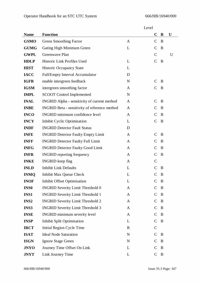
Operator Handbook for an STC UTC System 666/HB/16940/000
666/HB/16940/000 Issue 35-3 Page: 347
Level
Name Function C B U
GSMO Green Smoothing Factor A C B
GUMG Gating High Minimum Green L C B
GWPL Greenwave Plan C U
HDLP Historic Link Profiles Used L C B
HIST Historic Occupancy State L
IACC Full/Empty Interval Accumulator D
IGFB enable intergreen feedback N C B
IGSM intergreen smoothing factor A C B
IMPL SCOOT Control Implemented N
INAL INGRID Alpha - sensitivity of current method A C B
INBE INGRID Beta - sensitivity of reference method A C B
INCO INGRID minimum confidence level A C B
INCY Inhibit Cyclic Optimisation L C B
INDF INGRID Detector Fault Status D
INFE INGRID Detector Faulty Empty Limit A C B
INFF INGRID Detector Faulty Full Limit A C B
INFG INGRID Detector Faulty Good Limit A C B
INFR INGRID reporting frequency A C B
INKE INGRID keep flag A C
INLD Inhibit Link Defaults L C B
INMQ Inhibit Max Queue Check L C B
INOF Inhibit Offset Optimisation L C B
INS0 INGRID Severity Limit Threshold 0 A C B
INS1 INGRID Severity Limit Threshold 1 A C B
INS2 INGRID Severity Limit Threshold 2 A C B
INS3 INGRID Severity Limit Threshold 3 A C B
INSE INGRID minimum severity level A C B
INSP Inhibit Split Optimisation L C B
IRCT Initial Region Cycle Time R C
ISAT Ideal Node Saturation N C B
ISGN Ignore Stage Green N C B
JNYO Journey Time Offset On Link L C B
JNYT Link Journey Time L C B

Operator Handbook for an STC UTC System 666/HB/16940/000
666/HB/16940/000 Issue 35-3 Page: 348
Level
Name Function C B U
LFAL Link Flare Approach Lanes L C B
LFEL Link Flare Extra Lanes L C B
LFLA Link Flare L C B
LFMQ Link Flare Maximum Queue Clear Time L C B
LLEN Length of a Link L C B
LNKU Link Used Status L
LPUV User LPU Per Vehicle L C B
LRT1 LRT Saturation Limit 1 N C B
LRT2 LRT Saturation Limit 2 N C B
LRT3 LRT Saturation Limit 3 N C B
LRTS LRT Stage Permitted S C B
LRTU LRT UTC Pattern N C B
LSTS Link Fault Status L
LTT1 Link Travel Time Low Delay Threshold L C B
LTT2 Link Travel Time Medium Delay Threshold L C B
LTT3 Link Travel Time Heavy Delay Threshold L C B
LTTF Link travel time factor L C B
LTTM Link Travel Time L
LTTT Parameter for link travel calculation L C B
MAXC Maximum Cycle Time R C B
MAXS Maximum Stage Length S C
MCLL Max clear late stage A C B
MDSL Main Downstream Link L C
MFBI Model Feedback Inhibit N C B
MINC Minimum Cycle Time R C B
MINH MONACO Inhibit A C B
MINS Minimum Stage Length S C
MMWQ MONACO Minimum Wasted Queue A C B
MPCY Minimum Practical Cycle Time N
MPFB Multi-Pelican Node Feedback Mode N C B
MPFR Maximum Pedestrian Frequency N C B
MPWT Maximum Pedestrian Waiting Time N C B
MRNI MONACO Run Interval A C B

Operator Handbook for an STC UTC System 666/HB/16940/000
666/HB/16940/000 Issue 35-3 Page: 349
Level
Name Function C B U
MTWQ MONACO Threshold Wasted Queue A C B
MUJT MONACO Upper Journey Time A C B
NCMT No counts message time C U
NCYT Node Cycle Time N
NDCG Node Double Cycling Group N C B
NIGM New intergreen modelling method for multi-controller Nodes
N C B
NMIN Node Minimum Cycle Time N
NOAP Node Offset Authority Pointer N C B
NOBP Offset Bus Authority Pointer N C B
NSAP Node Split Authority Pointer N C B
NSBP Split Bus Authority Pointer N C B
NSST Named Stage Start Time N C
NSTG Named Stage N
NTST Previous and Current Region of a SCOOT Node N
OFST Offset Optimizer Status N C
OFWT Offset Weighting L C B
OOEW Offset optimiser emissions weight N C B
OPNI Operator Node Independence N C B
OPSI Operator Sub-Region Independence R C B
OVEP Bus EP Override Status N C B
PDCC Pay and display car park correction C U
PDCI Pedestrian Priority Double Cycling Inhibit N C B
PDCM Permanent Demand Checking Mode C U
PEDS Pedestrian Stage N C B
PFLG UTC System persistent Fault Log C U
PIGE Intersection Permanent Intergreen ExtensionLimit
C U
PLAN Plan Timings N
PLST Pedestrian Lower Saturation Threshold N C B
PMAX Bus Maximum Extension Time N C B
PPEL Permanent Pedestrian Stage MaximumExtension Limit
C U
PPRI Pedestrian Priority Level N C B

Operator Handbook for an STC UTC System 666/HB/16940/000
666/HB/16940/000 Issue 35-3 Page: 350
Level
Name Function C B U
PRTD Priority Route Duration C U
PRTP Priority Route Plan C U
PUST Pedestrian Upper Saturation Threshold N C B
QCMQ Maximum Queue Clear Time L C B
RCYT Region Cycle Time R
RDFF Reduced Detection Flow Factor L C B
RDFR Reduced Detection Flow Ratio L C B
RDPF Reduced Detection Proxy Flow L C B
RDPL Reduced Detection Proxy Link L C B
RSCT Resume SCOOT Timings R C B
SATE Bus Priority Extension Saturation N C B
SATR Bus Priority Recall Saturation N C B
SETH Suspect Empty Detector Fault Threshold A C B
SFBI Split Feedback Inhibit N C B
SFTH Suspect Full Detector Fault Threshold A C B
SJNY Soft Journey Time D C B
SKIC Skipping Inhibit Cycles N C
SKID Skipping Priority Level Difference N C
SKIF Skipping Priority Level N C B
SKIH Skipping Inhibit Period N C
SKIP Allow Skipping A C B
SKIT Skipping Inhibit Times S C
SKRM Bus Skipping Recovery Method N C B
SKTS Skipping Target Saturation L C
SLAG Start Lag L C B
SLAM Split Lambda Factor A C B
SLBI Stopline Link Bias L C B
SLUL Stopline Link Upstream Link L
SMAN SOFT Mandatory Status D C B
SMAX SOFT Maximum Saturation Occupancy L C B
SMIN SOFT Minimum Saturation Occupancy L C B
SMOI Split minimum optimisation inhibit N C B
SMOO Smoothing Factor C U

Operator Handbook for an STC UTC System 666/HB/16940/000
666/HB/16940/000 Issue 35-3 Page: 351
Level
Name Function C B U
SMUL Split Weighting Multiplier L C B
SNSI Gas Sensor Collection Interval A C B
SOFT SOFT status L C
SPEN Stop Penalty A C B
SPLT Split Optimiser Status N C
SRST Stage Removed Status S
SSAT Split Weighting Saturation L C B
STOC Saturation Occupancy L C B
SUPT Supplementary Link Type L C B
TACC ACCT Test Mode R C
TDS1 Decreasing threshold for state change downfrom 1
C U
TDS2 Decreasing threshold for state change downfrom 2
C U
TIS1 Increasing threshold for state change up to 1 C U
TIS2 Increasing threshold for state change up to 2 C U
TPLN Translation Plan N C
TRAF Traffic Period for empty detector fault checking D C B
TREN Cycle Time Trend Status R C B
TSAT Trend Node Saturation N C B
UNTS Up Node Through Stage L C
VEHC Vehicle Occupancy Count C U
VLAG Volume alarm time lag C U
VTHR One Minute Volume Alarm Threshold C U
ZRTM RTIG Traffic Movement Association U
ZRTP RTIG Trigger Pointy Association U
ZRTS RTIG Traffic Signal Number Association U
Operator Handbook for an STC UTC System 666/HB/16940/000
666/HB/16940/000 Issue 35-3 Page: 352
Appendix D - UTMC Outstation Concepts
UTMC ConceptsUTMC is an SNMP protocol. SNMP uses UDP/IP and so can be used on a widevariety of networks that support IP. Being SNMP, the protocol is principallydefined by a MIB. The original product was termed ‘UTMC29’ – from now onthe term ‘UTMC Type 1’ will be used instead of UTMC29, in order to distinguishit from the new product ‘UTMC Type 2’.The original UTMC Type 1 product came in two ‘flavours’ :
· The Siemens simple MIB, interacting with the Siemens Gemini outstation.
· The Peek, or ‘Full’ MIB, interacting with the Peek Chameleon outstation.The Siemens UTC system can connect to either the Siemens MIB or the PeekMIB. However, both MIBs are like the traditional communications systemsTelecommand 8 and Telecommand 12 because it is required that control and replymessages are to be sent to street equipment each and every second regardless ofwhether anything had changed.
Also with traditional UTC communications, if there is a communications faultwhen the OTU returns reply data to the instation, or if the data takes longer than asecond to send, then the data is lost. In addition, the time-stamping features ofSCOOT MC3 cannot be properly used.
UTMC Type 2This is often also referred to as ‘UG405’. UG405 is a UTMC initiative name forthe new UTC communications standard. The standard applies to communicationsbetween a UTC instation and the street equipment that it controls and monitors.
In this section, the shorthand term ‘UTMC2’ is used as a synonym for ‘UTMCType 2’. Note that ‘UTMC2’ has an alternative meaning as Version 2 of theUTMC Common Database MIB. However, there is no conflict of meaning in thissection, because of the specific context of UTMC Outstation Communications.
UTMC2 is intended to overcome deficiencies of the existing UTMC Type 1communications standard as well as adding features to give the end user morechoice in the kinds of IP communications network that can be used. In particular,the standard adds the support for time-stamped control and reply data which inconjunction with SCOOT MC3 allows the UTC system to better handle delays ordata loss introduced by the IP network.
UTMC2 is an SNMP protocol. SNMP uses UDP/IP and so can be used on a widevariety of networks that support IP. Being SNMP, the protocol is principallydefined by a MIB.UTMC2 differs from TC12, TC8 and UTMC Type 1 UTC simple (SiemensGemini) MIB operation in a number of ways.
Traditional UTC communications have required control and reply messages to besent to street equipment each and every second regardless of whether anythinghad changed. UTMC2, in its normal mode of operation, only requires data to be
Operator Handbook for an STC UTC System 666/HB/16940/000
666/HB/16940/000 Issue 35-3 Page: 353
sent when it changes. This mode of communications is referred to as control-by-exception and reply-by-exception.With traditional UTC communications, if there is a communications fault whenthe OTU returns reply data to the instation, or if the data takes longer than asecond to send, then the data is lost. With UTMC2, when using reply-by-exception mode, reply data is never lost whilst the OTU remains online to theinstation. The outstation will retry sending reply data to the instation until itreceives an acknowledgement that it has been received.Reply data is time-stamped at the outstation to allow the instation to process thedata correctly, regardless of whether the data was delayed by the network.Control data may be time-stamped for future execution. The instation can sendstage force bits ahead of time to avoid the effects of network delays. This isreferred to as ‘pre-scheduling’.
SCOOT detector data for a number of seconds can be batched together to reduceoverall network traffic.
The representation of the data has changed. With traditional UTCcommunications, the control and reply data has comprised anonymous raw bytesof data. Interpretation of the data was not part of the protocol. With UTMC2, theprotocol is described in terms of individual equipment functions – e.g. junctionforce bits, detector fault bits.UTMC2 is interoperable with both Siemens and Peek outstations. The UTCinstation will not have to be aware of the type of OTU to which it iscommunicating.
It should be noted that some of these features were part of the UTMC Type 1 FullUTC (Peek Chameleon) MIB.
To use SCOOT with UTMC2 OTUs you must have have a license to use SCOOTMC3. Earlier versions of SCOOT (e.g. 4.5) cannot be used with UTMC2 OTUs.This is because only SCOOT MC3 allows the use of delayed time-stamped replydata.The differences between traditional and UTMC2 communications are illustratedin the diagram in Figure 1 Overview Diagram.

Operator Handbook for an STC UTC System 666/HB/16940/000
666/HB/16940/000 Issue 35-3 Page: 354
Figure 1 Overview Diagram
Time SynchronisationTime-synchronisation is a very important part of using the UTMC2 protocol. Forthe protocol to work correctly, the instation and outstations must be synchronizedtogether (to within < 1second). The standard NTP protocol (Network TimeProtocol) is used for this. To avoid time discontinuities due to time drift, theinstation MUST be synchronized to a true-time clock source. The high availabilityof an accurate time source is mandatory for UTMC2. This can be provided in anumber of forms of which the simplest is an external time source such as aWharton clock that receives its time via GPS or the Rugby time signal. Mostsystems already incorporate some form of time-synchronization. Other timesources such as internet time server pools can be also be used. Any NTP timesources can be used as long as they can provide time of a sufficient quality. SNTPtime sources, whilst compatible at the protocol level, are not of sufficient quality.The way NTP works is by gradually speeding up or slowing up the computer'sclock to be in sync with the time source making it unnecessary to perform stepchanges to the time. The system clock is 'trained' by NTP so that even if the timesource is not available for a while, clock accuracy is maintained.
If a time variance between the instation and a UTMC2 OTU is detected then theinstation will flag a fault and not use the OTU. It will continue to re-attempt
Operator Handbook for an STC UTC System 666/HB/16940/000
666/HB/16940/000 Issue 35-3 Page: 355
communicating every few seconds or so once the OTU time is correct it will comeonline automatically.Manual time changes on the instation should be avoided. It should be unnecessarygiven that the system should be synchronized to a true time source. If you domake a manual time change then it is likely that all the UTMC2 OTUs will gooffline within 30 seconds. They will not come back online until their clocks havesynchronized with the new instation time which may take several minutes.
Control and Reply Bit ConfigurationIn terms of the UTMC2 protocol, the UTC system is not aware of how the bits arewired at the OTU - e.g. it just sets the F bits for J32111 - it does not know howthey are mapped at the OTU. However, internally the UTC software views aUTMC2 OTU like a TC12 OTU which is why you still have to configure the bitpositions for the F bits. Where you actually configure the F bits doesn't reallymatter but, of course, it makes it so much more convenient if it matches the realOTU (where appropriate). Additionally, for Gemini UTMC2 OTUs, the bitmapping that you enter in data-entry can be exported as a CSV file. This data canthen be imported into the Gemini configurator tool and used as the basis for theGemini configuration.
If the UTMC2 OTU is configured differently from how the instation expects it tobe then the instation will report a configuration mismatch error and stopcommunicating with that OTU. For example, supposing a traffic controller hasbeen configured with a new bit, SO say. You've wired it up to the OTU andyou've also added the SO bit to the junction's (J01111) data word format at theinstation. In this situation, the instation will raise an error against the[utcControlSO.'J01111'] object. The OTU configuration must also be updated toinclude the mapping for the new control bit before the OTU will come backonline.
Pre-scheduled Plan ControlUTMC2 outstations support the pre-scheduling of control data. This is used by theUTC system when running fixed time and SCOOT plans to send junction andpelican stage force bits (and other bits required for plan control) a number ofseconds before their actual execution time. The purpose of doing this is to makecontrol more resilient to network delays or drop-offs. For example, if force bitsare sent 2 seconds before the execution time, then even if there is acommunications drop-off for the couple of seconds at the stage change time, theforce bits will still be executed at the right time.The extent to which the UTC system will consider pre-scheduling is specified bythe communications profile - but the recommended and default value is 4 seconds.
Controllers under fixed-time plans can reap the full benefits of pre-scheduledcontrol because the control pattern is entirely predictable and not subject tochange. With SCOOT, however, the stage timings are subject to change by theoptimisers - sometimes, with very little notice. For instance, the split optimisers

Operator Handbook for an STC UTC System 666/HB/16940/000
666/HB/16940/000 Issue 35-3 Page: 356
run 5 seconds before the next stage time. The optimiser can decide to advance,stay or retard the stage change time by up to 4 seconds. If the decision is a stay orretard decision (the stage change occurs later) then the plan control bits can bepre-scheduled to the full extent of 4 seconds. If the decision is an advancedecision (the stage change occurs sooner) then there is less time available for pre-scheduling. If the advance decision is the maximum of 4 seconds, then there is notime for pre-scheduling as the stage change occurs next second. In other words,pre-scheduling can help to minimize the effects of poor communications withSCOOT control but cannot eliminate it.
Communications ProfilesThere are several parameters that can be set for UTMC2 communications. Anumber of these are difficult to understand without full knowledge of theunderlying protocol. To simplify the process of setting up OTUs for usersrecommended settings have been grouped together into different communicationsprofiles. When a UTC system is first converted to support UTMC2 a set of pre-defined communications profiles is created. Also, all existing non-UTMC2outstations are pre-set to profile zero. Profile zero is an indication to use theexisting communications tolerances in System-Wide Variants. Thus existingOTUs will still work as before.For each UTMC2 OTU, the user selects which communications profile they wishto use based on the kind of line in use. The existing profiles can be modified ornew profiles can be created by advanced users or Siemens engineers. It isrecommended that new profiles be created instead of modifying the pre-definedprofiles.
The profiles also support the older OTU types (TC8, TC12, UTMC Type 1).For more information on the Communications Profiles parameters see the Profilessection in 666/HI/16940/000, the Data File Format Guide.
Communications MonitoringThe methods of monitoring and reporting OTU communications faults havenecessarily had to change for UTMC2 OTUs. This section describes howoutstation communications are monitored and when faults are raised. Values with(P) are communications profile values that can be modified by the user.
Offline fault [525]this fault is raised if the instation cannot communicate with the OTU orif there has been a protocol or configuration error of some kind. Therewill normally be other fault messages to describe the reason. Theinstation will attempt to establish communications with the OTU everyfew seconds
TX Fault - No reply [511]

Operator Handbook for an STC UTC System 666/HB/16940/000
666/HB/16940/000 Issue 35-3 Page: 357
this fault is raised if the instation takes longer than 4 (P) seconds tosend a message or if the instation receives reply data which itestablishes took longer than 4 seconds for the OTU to deliver. Theclearance time is 30 (P) seconds
The following two faults count the number of late messages seen over a certainperiod. A late message is one which takes longer than 3 (P) seconds to bedelivered.
Persistent TX Fault [512].This is raised if 15 (P) late messages are seen together occuring at arate >= 1 per 3 (P) minutes.
Intermittent TX Faults [513].
This is raised if 15 (P) late messages are seen in one clock hour.Every hour, the system will output the number of late messages seen on everyOTU. This count can also be seen on the MONI display.
There are some new event-driven messages that can be used to outputcommunications statistics every five minutes. These event messages are OTUlevel.
U80: instation message summary: the number of messages sent andacknowledged/unacknowledged.
U81: round-trip time of instation message requests in milliseconds.best/worst/avaerage
U82: longest drop-off: the number of times OTU has come on or offline.U83: Estimated delay lag of reply message sent by OTU to instation in
seconds.
Of these, the values that are mostly likely to be of interest are the number ofunacknowledged messages from U80 and the average round-trip time from U81.The default ASTRID configuration has been updated to include graphing for thesetwo data items. To collect this data, include MESS U80 X00000 >ASTRID andMESS U81 X00000 >ASTRID commands in your ASTRID start up CAST.
Operator Handbook for an STC UTC System 666/HB/16940/000
666/HB/16940/000 Issue 35-3 Page: 358
INDEXACAS, 16, 40, 74, 110, 125, 166ACCT, 41, 121, 251
ACKD, 42, 44, 146, 148Acknowledge fault(s) and cancel alarm, 42
ACSV, 43, 122, 252Action CAST, 40
Action CAST by Cycle Time, 41Action CAST by Saturation/Congestion,
47Action CAST by Sensor Values, 43
Action the CHANs in a selected CASTin Cancel CHAN Priority mode, 292
Action the CHANs in a selected CAST inPriority mode, 196
ADJU, 62, 76AFIT, 307
Allow "dial-up" terminal access, 81Almost Full Increasing Threshold, 307
ALRM, 44Analogue Sensor Data Output Interval, 311
APSR, 307ARCM, 45
ARRQ, 46, 123, 254ASCC, 47, 124, 255
ASLD, 48, 71, 136, 212Assign SCOOT link to count site, 48
Associate count detectors with summingpseudo detector, 71
Associate three CASTs and timer withRemote Request, 46
ASTC, 49ASTD, 49
AUDI, 50, 55, 256AUTH, 51
Automatic Plan Selection Re-Run Interval,307
Average SCOOT Plan, 53AVSP, 53
baseline, 194Broadcast message, 39
Call Special Facility, 70CANA, 55
Cancel ACSV Command, 252Cancel Action CAST by
Saturation/Congestion, 255Cancel all operator timetable overrides,
299Cancel AM/PM Tram Priority, 303
Cancel APS, 253Cancel APS in test mode, 300
Cancel car park state control, 257Cancel controller isolation, 281
Cancel dimming override bit, 266Cancel Equipment Message, 268
Cancel fault, 272Cancel flashing amber mode, 270
Cancel forced demand(s) on a particularstage, 263
Cancel Inhibited Fault, 276Cancel inhibition of weekly flow analysis,
280Cancel local link inhibit bit, 283
Cancel logging of OTU control & replybits, 284
Cancel logging of stage timings data, 298Cancel manual hurry call, 275
Cancel MOVA Control Mode, 288Cancel operator fixed-time plan, 289
Cancel operator green wave, 274
Operator Handbook for an STC UTC System 666/HB/16940/000
666/HB/16940/000 Issue 35-3 Page: 359
Cancel SCOOT control, 293
Cancel sign legend override, 295Cancel spooled output, 297
Cancel Tidal Flow control, 302Cancel Tram Priority Inhibition, 279
Cancel Tunnel Control, 306Cancel wall map or SIP lamp test, 301
Cancels a Priority CHAN, 258CAPA, 307
Car park capacity, 307car park group search list, 203
Car Park Occupancy Prediction SmoothingFactor, 308
Car Park Queueing Time for Range 1, 308Car Park signs, 213
Car Parks, 58, 213CARP, 56, 257
CASP, 308CASTS, 16
CDBC, 57CHAN, 58, 95, 106, 156, 194, 213, 245
Change Car Park group search list, 203Change pelican controller checks mode, 61
Change Stage Offsets, 172Change Tunnel Lane flow direction, 229
Change value of parameter, 58Changeover to standby computer, 63
CHCK, 59, 208, 259CHCP, 59, 61
CHDC, 62, 76CHGO, 63, 260
CHSI, 64, 261CJNL, 65, 135, 173
CJNY, 308Clear fall-back mode bit, 269
Clear Journal, 65
CLOS, 66, 174, 213Close car park, 66
COMM, 308Command Prompt, 35
Commence output of event message, 159Configure Terminals and Users, 228
Congestion Alarm Clear Percentage, 307Congestion Alarm Set Percentage, 308
COPS, 308CPOC, 67, 68
CPOP, 68CQT1, 308
CQT2, 309CQT3, 309
CQT4, 309Create Fault Group, 102
CREP, 69CSFY, 70, 200, 262, 294
CSUM, 71DATE, 72, 222
DBAS, 45, 73, 91, 227, 228, 244DCAS, 16, 40, 74, 91, 110, 125, 166
DCOF, 75, 126, 188, 234DCOU, 62, 76
DDFV, 77Delete an entry from a CAST, 74
Delete CAST Association with RegionCycle Time, 251
Delete previously RUBAed data, 291DEMA, 78, 263
De-select special facility, 262DGUL, 80
DIAL, 81, 96, 265Difference against user baseline, 90

Operator Handbook for an STC UTC System 666/HB/16940/000
666/HB/16940/000 Issue 35-3 Page: 360
DIMO, 82, 266
DIPM, 83, 94, 183, 268Disable audible alarms, 256
Disable dial up access, 265Disable log printer, 290
Disable output of unsolicited messages,224
Disable part time signals, 204Disconnect outstation, 85
DISO, 85, 119, 267, 278, 281Display analogue sensor values, 206
Display Car Park Occupancy, 67Display Car Park Occupancy Prediction,
68Display current analogue sensor value, 205
Display current sensor values, 207Display database values, 198
Display Default Values, 77Display detector flow monitor, 100
Display information forOTU/User/Terminal, 115
Display logged OTU data, 86Display or modify current date, 72
Display or modify current time, 222Display outstation monitor, 161
Display picture, 181Display plan monitor, 83
Display SCOOT GULP data, 80Display SCOOT link profile and queue,
247Display survey flow counts, 214
Display weekly detector flow counts, 249Diversion, 118
Diversions, 213DIVR, 309
DLOT, 69, 86, 144, 285
double cycling, 191
Download data to an outstation, 235DSSG, 88, 209, 298
DUBA, 90, 106Earliest date of System files available, 93
ECAS, 91, 110, 125, 166ECHO, 92
Echo Message to Terminal, 92EDAV, 91, 93, 140, 142, 175, 249
Edit Noticeboard, 97EMES, 94, 127, 268
EMIX, 95Enable audible alarms, 50
Enable log printer, 186Enable output to a terminal, 304
ENDS, 81, 96, 265Engine Mix for a Link, 95
ENOT, 97, 171Environmental Sensors, 324
Equipment message, 94Erase fault category group, 271
FALL, 98, 269Fault Groups, 33
Fault Log viewer for uploaded fault logs,236
FDTH, 309Figure 1 Overview Diagram, 357
FITH, 309FLAS, 99, 270
FLOW, 100, 104, 175, 214, 249FLTA, 101, 129, 273
FLTG, 102, 128, 271, 272FLTY, 103, 272
Force demand on a particular stage, 78forced double cycling, 191

Operator Handbook for an STC UTC System 666/HB/16940/000
666/HB/16940/000 Issue 35-3 Page: 361
forced single cycling, 191
Full Decreasing Threshold, 309Full Increasing Threshold, 309
GDDD, 104Generate semi-graphic pictures, 105
GENP, 105, 151, 181Graphical Detector Data Display, 104
Green Red entrance threshold, 309Green Wave Plan number, 309
GRET, 309GUBA, 106
GULP, 80GWAV, 107, 149, 274
HELP, 108HRYC, 109, 275
ICAS, 16, 40, 74, 91, 110, 125, 166IFLT, 111
IHPC, 112, 277IHRW, 113, 131, 278
IHTP, 114, 279Implement immediate time
synchronisation, 225Implement SCOOT control, 197
INFO, 115Inhibit Fault by Category, 111
Inhibit Plan Compliance fault isolation,112
Inhibit reply word analysis, 113Inhibit special facility selection, 200
Inhibit tram priority, 114Inhibit weekly flow analysis, 117
INHW, 117, 175, 280Initiate SCOOT detector counts checking,
62Insert an entry into a CAST, 110
Insert Clear Journal command into thejournal, 65
INTD, 118, 190
Introduce diversion, 118Introduce updated databases, 243
ISOL, 119, 267, 278, 281Isolate controller, 119
KILL, 120LACC, 41, 121, 251
LACS, 43, 122, 252LARR, 46, 123, 254
LASC, 47, 124, 255LCAS, 16, 40, 74, 110, 125, 166
LCOF, 75, 126, 188, 234LEME, 94, 127, 268
LFLG, 102, 128, 271, 272LFTA, 129
LIFT, 130LIHR, 131
LIHS, 132Link Occupancy Monitor, 138
Link Validation Display, 157LIPT, 133, 183, 184, 289
List Action CAST bySaturation/Congestion Event Triggers,124
List active CASTs actioned by sensors,122
List active event driven messages, 150
List all the Priority CHANs in effect, 145List car park, 213
List car park occupancy files, 126List car park sign, 213
List CAST Associations, 121List CASTs associated with remote
requests, 123List command journal, 135

Operator Handbook for an STC UTC System 666/HB/16940/000
666/HB/16940/000 Issue 35-3 Page: 362
List contents of timetable, 176
List Current Tram Priority, 155List diversion sign status, 213
List equipment, 250List Equipment History, 132
List equipment messages, 127List equipments with reply word analysis
inhibited, 131List Event Message Log, 140
List fault category groups, 128List Faults, 148
List Faults which raise System Alarms,129
List flow detector status, 147List green wave routes, 149
List Inhibited Faults, 130List link conversion factors, 136
List message log, 141List network message commands, 139
List output of SCOOT detector checks, 76,77
List picture titles, 151List plan timings, 133
List special facility status, 213List status, 152
List the contents of a CAST, 125List transmission error counts, 154
List Unacknowledged Alarms, 146List Upload/Download status, 240
List user baseline, 156List value of SCOOT parameter, 245
List weighted averages table, 248LIVE, 134, 282
LJNL, 65, 135, 173LLCF, 48, 71, 136, 212
LLNK, 137, 283
LMON, 138, 158, 168, 191
LNMC, 139, 169Log OTU control and reply bits, 143
Log stage timings data to data file, 209LOGM, 77, 140, 160
LOGO, 93, 132, 141LOTU, 69, 87, 143, 180, 285
LSCH, 145LSTA, 42, 44, 146, 148
LSTD, 147, 175, 214, 249LSTF, 42, 94, 103, 146, 148, 236, 268, 272
LSTG, 107, 149, 274LSTM, 140, 150, 160, 286
LSTP, 105, 151, 181LSTS, 79, 152, 263, 277
LTEC, 154LTRA, 155, 303
LUBA, 58, 90, 95, 106, 156, 194LVAL, 138, 157, 168, 187, 191
MAN MACHINE INTERFACE, 17Manual Hurry Call, 109
Manual Wave Display, 165Map Editor and Display, 26
MESS, 77, 150, 159, 286MMI, 17
Modify Upload/Download transfer mode,238
MONI, 69, 87, 144, 161, 180, 285Mouse, 17
MOVA, 163, 288MOVE, 164, 287
Move count detector, 164MWAV, 109, 165
Name a CAST, 166NCAS, 16, 39, 40, 74, 91, 110, 125, 166

Operator Handbook for an STC UTC System 666/HB/16940/000
666/HB/16940/000 Issue 35-3 Page: 363
NCMT, 310
NFTD, 138, 158, 167, 191NMCS, 139, 169
No Counts Message Time, 310Node Fine Tuning Display, 167
NODT, 170NOTB, 97, 171
Noticeboard, 171OFST, 172, 183, 184, 246, 289
OJNL, 173One Minute Volume Alarm Threshold, 313
Online HELP facility, 108OPEN, 66, 174, 213
Open car park, 174OPERATOR COMMANDS, 35
OPFD, 93, 100, 117, 175, 214, 249, 280Optimise the journal, 173
Optional Parameters, 35Output weekly flow analysis, 175
OUTT, 176, 215, 299Override Communications Profile, 308
Override control/reply bits, 178Override sign legend, 201
OVRB, 69, 87, 144, 178, 285Pay and Display Carpark Correction, 310
PDCC, 310Permanent Intergreen Extension Limit, 311
Persistent Fault Log, 311PFLG, 311
PICT, 105, 151, 181PIGE, 311
PLAN, 182, 184, 289Pollution Monitoring, 324
PPRP, 73, 172, 183, 184, 246Prepare plan data, 184
PRIN, 186, 290
Print logged stage timings data, 88Print LVAL log, 187
Print OTU Reply bit count, 69Priority Route Duration, 312
Priority RoutePlan, 312PRTD, 312
PRTP, 312PVAL, 158, 187
Raise User Defined Operational Alarm, 44RCOF, 75, 126, 188, 234
Re-connect outstation, 267Record car park occupancy file, 188
Record user baseline, 194Re-enable plan compliance fault isolation,
277Re-enable reply word analysis, 278
Re-enable special facility selection, 294Region Fine Tuning Display, 191
REIN, 189, 244Reinitialise SCOOT databases, 189
REMD, 118, 190Remote Handset facility, 239
Remote Request, 46Remove a Moveable Count Detector from
an OTU, 287Remove Association Between Remote
Request and CASTs, 254Remove command from Temporary
TimeTable, 305Remove diversion, 190
Restore Recorded User Baseline Data, 106Resume normal TCC operation, 260
RFTD, 138, 158, 168, 191RRUL, 192
RSTA, 193

Operator Handbook for an STC UTC System 666/HB/16940/000
666/HB/16940/000 Issue 35-3 Page: 364
RTIG Traffic Movement Association, 313
RTIG Traffic Point Association, 314RTIG Traffic Signal Number Association,
314RUBA, 58, 90, 95, 106, 156, 194
Run database preparation process, 73SAPS, 195, 253, 300
SCAS, 58, 196SCOO, 197, 293
SCOOT, 58SCOOT 3.1, 51
SEED, 198, 202SEES, 245
Select plan, 182Select Raid rules file, 192
Select SCNs to Send to Common dataBase, 57
Send command to NMCS computers, 169Send message to SIESPACE Car Park PC,
210Set controller to flashing mode, 99
Set fault manually, 103Set MOVA Priority Control, 163
Set Tram Priority, 223SFNO, 70, 200, 262, 294
Shut down and restart UTC computer, 193Shutdown System, 120
SIGN, 56, 201, 213, 257, 295Sign exercising, 64
SIGO, 203Silence Audible Alarm, 55
SIMU, 282SLOF, 204, 296
SMOO, 312Smoothing factor for congestion, 312
SNSD, 205, 206, 207
SNSI, 311
SNSS, 205, 206, 207SNSV, 205, 206, 207
SORT, 208Sort Controller Checks Messages, 208
Special Facilities, 213Special Facility, 200, 262, 294
Specify which Faults raise a SystemAlarm, 101
Specify which Faults should not raise aSystem Alarm, 273
SSGM, 89, 209, 298SSPC, 210
SSSU, 48, 136, 211Start APS in test mode, 217
Start Automatic Plan Selection, 195Start Car Park state control, 56
Start controller test sequence checking, 59Start operator green wave, 107
Start removable disk archive, 45Start SCOOT survey, 211
Start sign exercising, 64Start simulation of an equipment, 282
Start Tidal Flow control, 221Start Timetable Preparation Process, 226
Start up the ASTRID Display, 49STCS, 56, 202, 213, 257, 295
Stop controller test sequence checking, 259Stop output of event message, 286
Stop sign exercising, 261Stop simulation of an equipment, 134
Supersede Timetable, 215SURV, 93, 100, 175, 214, 249
SUTT, 215, 299SYNC, 216
Synchronise group timers, 216

Operator Handbook for an STC UTC System 666/HB/16940/000
666/HB/16940/000 Issue 35-3 Page: 365
TAPS, 195, 217, 253, 300
TAUC, 91TDDD, 219
Terminate dial-up session, 96TEST, 220, 301
Test Wall map or alarm panel, 220Tidal flow, 302
TIDL, 221, 302TIME, 72, 222
Time/Distance diagram display, 219Transfer a SCOOT node to another region,
170Transfer Data File to a PC, 230
Transmit dimming override bit, 82Transmit fall-back mode bit, 98
Transmit local link inhibit bit, 137TRAP, 155, 223, 303
TROF, 224, 304TSYN, 225
TTBP, 73, 91, 226TUAC, 73, 227, 228, 244
TUNL, 229, 306Turn part time signals on, 296
TXDF, 160, 230U01, 315
U02, 315U03, 315
U04, 315U05, 315
U06, 315U07, 315
U09, 316U10, 316
U11, 316U12, 316
U15, 317
U16, 317U17, 317
U18, 317U19, 318
U22, 318U26, 319
U27, 319U28, 319
U80, 320U81, 320
U82, 320U83, 320
UCOF, 75, 126, 188, 234UDDL, 235, 237, 238, 239, 240, 242
UDFV, 235, 236UDLC, 237
UDMC, 238UDRH, 237, 238, 239, 240, 242
UDSL, 237, 239, 240, 242UDUL, 236, 237, 238, 239, 240, 241
UPDA, 73, 91, 227, 228, 243Upload data from outstations, 241
Upload/Download line check andconfiguration, 237
Use car park occupancy file, 234User Configurable Optimiser Authorities,
51UTMC Outstation Concepts, 355
UTMC Type 2, 355VALU, 58, 95, 106, 156, 194, 213, 245
VARY, 172, 183, 184, 246, 289Vary stage green times, 246
VEGA, 247VEHC, 313
Vehicle count, 313

Operator Handbook for an STC UTC System 666/HB/16940/000
666/HB/16940/000 Issue 35-3 Page: 366
VLAG, 312, 313
VMS to car park journey time, 308Volume alarm lag time, 312, 313
VTHR, 313WAVC, 68, 248
WEEK, 93, 100, 104, 175, 214, 249WHAT, 250
XACC, 41, 121, 251XACS, 43, 122, 252
XAPS, 195, 218, 253, 300XARR, 46, 123, 254
XASC, 47, 124, 255XAUD, 50, 55, 256
XCAR, 56, 257XCHA, 196, 258
XCHC, 59, 208, 259XCHG, 63, 260
XCHS, 64, 261XCSF, 70, 200, 262, 294
XDEM, 78, 263XDIA, 81, 96, 265
XDIM, 82, 266XDIS, 85, 119, 267, 278, 281
XEME, 94, 127, 268XFAL, 98, 269
XFLA, 99, 270XFLG, 102, 128, 271, 272
XFLT, 102, 103, 128, 271, 272XFTA, 101, 129, 273
XGUL, 80XGWA, 107, 149, 274
XHRY, 109, 275XIFT, 276
XIHP, 112, 277
XIHR, 113, 131, 278XIHT, 114, 279
XINH, 117, 175, 280XISO, 119, 267, 278, 281
XLIV, 134, 282XLLN, 137, 283
XLOT, 69, 87, 144, 284XMES, 150, 160, 286
XMOV, 164, 287XMVA, 163, 288
XPLA, 172, 183, 184, 246, 289XPRI, 186, 290
XRUB, 291XSCA, 58, 292
XSCO, 197, 293XSFN, 70, 200, 262, 294
XSIG, 56, 202, 213, 295XSLO, 204, 296
XSPO, 297XSSG, 89, 209, 298
XSUT, 215, 299XTAP, 195, 218, 253, 300
XTES, 220, 301XTID, 221, 302
XTRA, 155, 223, 303XTRO, 224, 304
XTTC, 305XTUN, 229, 306
ZRTM, 313ZRTP, 314
ZRTS, 314


