Data File Format Guide for an STC UTC System - Siemens · EQUIPMENT FILE - DATA.MAC 11 ... 3.15...
96
Data File Format Guide for an STC UTC System 666/HI/16940/000 666/HI/16940/000 Issue 35 Page i Siemens Mobility, Traffic Solutions, Sopers Lane, POOLE, Dorset. BH17 7ER. SYSTEM/PROJECT/PRODUCT: STC UTC Data File Format Guide for an STC UTC System This is an unpublished work the copyright in which vests in Siemens plc. All rights reserved. The information contained herein is the property of Siemens plc and is supplied without liability for errors or omissions. No part may be reproduced or used except as authorised by contract or other written permission. The copyright and the foregoing restriction on reproduction and use extend to all the media in which this information may be embodied.
-
Upload
truongquynh -
Category
Documents
-
view
230 -
download
1
Transcript of Data File Format Guide for an STC UTC System - Siemens · EQUIPMENT FILE - DATA.MAC 11 ... 3.15...
Data File Format Guide for an STC UTC System 666/HI/16940/000
666/HI/16940/000 Issue 35 Page i
Siemens Mobility, Traffic Solutions,Sopers Lane,POOLE, Dorset.BH17 7ER.SYSTEM/PROJECT/PRODUCT: STC UTC
Data File Format Guide
for an STC UTC System
This is an unpublished work the copyright in which vests in Siemens plc. All rights reserved.The information contained herein is the property of Siemens plc and is supplied without liability for errors or omissions. No part may bereproduced or used except as authorised by contract or other written permission. The copyright and the foregoing restriction on reproduction anduse extend to all the media in which this information may be embodied.
Data File Format Guide for an STC UTC System 666/HI/16940/000
666/HI/16940/000 Issue 35 Page ii
ISSUE STATENote :- Source of documents is shown under Type as below.1=Paper, 2=VAX, 3=Microfilm, 4=CALTEXT Disc, 5=DECmate Disc,
6=Paper Insert, 7=MAC Disc, 8=LIFESPAN, 9=SUN, 10=Other - add note*.The document comprises the following components :-
CurrentPages Issue Type Part ID File IDAll 34 10 666/HI/16940/000 hi16940_V34-1.docx*Note : Document stored under AutoManager Meridian
Data File Format Guide for an STC UTC System 666/HI/16940/000
666/HI/16940/000 Issue 35 Page i
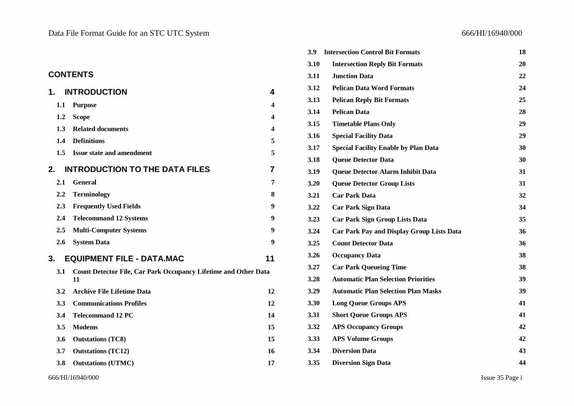
CONTENTS
1. INTRODUCTION 41.1 Purpose 4
1.2 Scope 4
1.3 Related documents 4
1.4 Definitions 5
1.5 Issue state and amendment 5
2. INTRODUCTION TO THE DATA FILES 72.1 General 7
2.2 Terminology 8
2.3 Frequently Used Fields 9
2.4 Telecommand 12 Systems 9
2.5 Multi-Computer Systems 9
2.6 System Data 9
3. EQUIPMENT FILE - DATA.MAC 113.1 Count Detector File, Car Park Occupancy Lifetime and Other Data
11
3.2 Archive File Lifetime Data 12
3.3 Communications Profiles 12
3.4 Telecommand 12 PC 14
3.5 Modems 15
3.6 Outstations (TC8) 15
3.7 Outstations (TC12) 16
3.8 Outstations (UTMC) 17
3.9 Intersection Control Bit Formats 18
3.10 Intersection Reply Bit Formats 20
3.11 Junction Data 22
3.12 Pelican Data Word Formats 24
3.13 Pelican Reply Bit Formats 25
3.14 Pelican Data 28
3.15 Timetable Plans Only 29
3.16 Special Facility Data 29
3.17 Special Facility Enable by Plan Data 30
3.18 Queue Detector Data 30
3.19 Queue Detector Alarm Inhibit Data 31
3.20 Queue Detector Group Lists 31
3.21 Car Park Data 32
3.22 Car Park Sign Data 34
3.23 Car Park Sign Group Lists Data 35
3.24 Car Park Pay and Display Group Lists Data 36
3.25 Count Detector Data 36
3.26 Occupancy Data 38
3.27 Car Park Queueing Time 38
3.28 Automatic Plan Selection Priorities 39
3.29 Automatic Plan Selection Plan Masks 39
3.30 Long Queue Groups APS 41
3.31 Short Queue Groups APS 41
3.32 APS Occupancy Groups 42
3.33 APS Volume Groups 42
3.34 Diversion Data 43
3.35 Diversion Sign Data 44

Data File Format Guide for an STC UTC System 666/HI/16940/000
666/HI/16940/000 Issue 35 Page ii
3.36 NMCS Controlled Equipments 45
3.37 Diversion Sign Aspect Data 45
3.38 Diversion Lists 45
3.39 Ripple Diversion Lists 46
3.40 Plan Diversion Rule Tables 47
3.41 Diversion Day Sectors 47
3.42 Diversion Plan Delay Switching Timetables 48
3.43 Automatic Diversion Selection Masks Data 49
3.44 Dependent Diversion Rule Tables 49
3.45 Congestion Group Automatic Diversion Selection 50
3.46 Long Queue Groups Automatic Diversion Selection 51
3.47 Short Queue Groups Automatic Diversion Selection 52
3.48 Volume Group Automatic Diversion Selection 52
3.49 Remote Request Data 53
3.50 User Defined Data 55
3.51 FOG Sub-area Data 55
3.52 Digital IO Wall Map Word Data (TC12 ONLY) 55
3.53 Wall Map Data 56
3.54 Fault Code Data 56
3.55 Tidal Flow Data 57
3.56 Aspect Data 58
3.57 Analogue Sensor Data 58
3.58 Analogue Sensor Group Data 59
4. UTC SCN DATA - SCNS.MAC 614.1 Introduction 61
4.2 Hardware (Computer) SCN To IRN Conversion 61
4.3 Telecommand 12 PCs 61
4.4 Subarea - CPU Data 61
4.5 Sub-area - SCN Data 62
4.6 SCOOT Node SCN To IRN Conversion 62
4.7 SCOOT Region CPU Data 62
4.8 Green Wave SCN To IRN Conversion 63
4.9 OMU Data 63
4.10 NMCS Data 63
5. JUNCTION TIMINGS DATA - TIMINGS.DAT 645.1 Timing Tolerances 64
5.2 General System-wide Timings 64
5.3 Controller Timings - Intersections 65
5.4 Controller Timings - Stage Timings 65
5.5 Controller timings - Upper Stage Timings 66
5.6 Controller Timings - Fallback And Test 67
5.7 Controller Timings - Cyclic Test Sequence 67
5.8 Controller Timings - Non-Cyclic Test Sequence 68
5.9 Controller Timings - Secondary Green Tests 68
6. SCOOT DATA 706.1 Area Data 70
6.2 Region Data 71
6.3 Node Data 72
6.4 Equipment Data 73
6.5 Stage Data 73
6.6 Stage Skipping Data 74
6.7 Link Data 75

Data File Format Guide for an STC UTC System 666/HI/16940/000
666/HI/16940/000 Issue 35 Page iii
6.8 SOFT detector data 77
6.9 Bus detector data 77
6.10 Link Stage data 78
6.11 Detector Data 79
7. TIMETABLES 807.1 Dwyttb Timetables 80
7.2 TOD'n'.MAC Timetables 81
8. TERMINAL DATA FILE - TRMCNF.DAT 85
8.1 Printer data 85
8.2 Terminal 86
8.3 Modem Ports 88
8.4 Dial-up Users 88
8.5 Daylight Saving Time 90
8.6 System Printer 90
9. PLAN FORMATS 92
Data File Format Guide for an STC UTC System 666/HI/16940/000
666/HI/16940/000 Issue 35 Page 4
1. INTRODUCTION
1.1 PurposeThe purpose of this document is to describe the formats of the data files which are produced by the list option of the data preparationsystems which may help you to check the validity of the data stored within a UTC System.
1.2 ScopeThe document is written for day-to-day users of a System which is capable of running SCOOT Version 2.4 or later. Users of thehandbook should have attended an STC Data Preparation training course.
1.3 Related documentsNote: In the references below, the characters 'xxx' substitute for the 3 digit number which uniquely identifies a particular UTCSystem i.e. the customer variant for these documents.
1.3.1 666/UH/16940/000 Systems Requirement Specification for an STC UTC System
1.3.2 666/UH/16940/xxx Customer Requirements Specification
1.3.3 666/HA/16940/000 Hardware & Maintenance Handbook
1.3.4 666/HB/16940/000 Operators Handbook for an STC UTC System
1.3.5 666/HD/16940/000 Data Preparation Handbook for an STC UTC System
1.3.6 666/HE/16940/000 System Handbook for an STC UTC System
1.3.7 666/HF/16940/000 SCOOT User Guide
1.3.8 666/HG/16940/000 System Management Handbook for an STC UTC System
1.3.9 666/HH/16940/000 Guide to Data Preparation
1.3.10 666/HB/16101/002 SCOOT V2.4 Traffic Handbook

Data File Format Guide for an STC UTC System 666/HI/16940/000
666/HI/16940/000 Issue 35 Page 5
1.3.11 666/HP/16940/000 Plan Preparation Handbook for a STC UTC System
1.3.12 666/HT/16940/000 Timetable Preparation Handbook for an STC UTC System
1.4 DefinitionsFor all definitions and abbreviations used in this and related UTC documentation see 666/KE/16066/000 UTC Glossary of Terms.
1.5 Issue state and amendmentIssue 01.00A - First draft
Issue 01.00B - Second draft after informal review
Issue 01.00 - First numeric issueIssue 02.00 - Inclusion of upper and lower controller timings, Summer Time, System printer and Dial-up terminal.
Modification of Terminal data.Issue 03.00 - 9th February 1993, DC 7573, Inclusion of Telecommand 12, multi-computer systems and tidal flow data.
Issues 04 to 06 - Not Issued.Issue 07.0 - Updates and amendments. Document issue now aligned with Software Issue.
Issue 08.0 - November 1993, inclusion of plan file formats, changes for more than 2 demand dependent stages and newremote request types.
Issue 09.0 - Not issued.Issue 10.0 - Revised and updated to reflect V10 software.
Issue 10.0 to 16.0 Not IssuedIssue 17.0 - Modified to Microsoft Word and updated to reflect version 17.0 of the UTC software
Issue 18 to 20 Not IssuedIssue 21 Revised and updated to reflect V21 software.
Issue 22 Not IssuedIssue 23 Revised and updated to reflect V23 software.
Data File Format Guide for an STC UTC System 666/HI/16940/000
666/HI/16940/000 Issue 35 Page 6
Issue 24 Not issued
Issue 25 Not issuedIssue 26 Revised and updated for Lincoln Tidal Flow modifications at V26 software.
Issue 27 Not issuedIssue 28 Updated
Issue 29 Not issuedIssue 30 Updated for communications profiles for UTMC mark 2 (UG405)
Issue 31 Not issuedIssue 32 Add CO reply bit for junctions & pelicans
Issue 33 Not issuedIssue 34 For TC12 and UTMC OTUs allow position of first SCOOT detector to be specified manually.
Number of bits in junction and pelican formats increased from 19 to 32. This can only be accessed from HTMLdata entry.
Allow MOVA configuration on pedestrian controllers Allow PV control bit for junctions
Data File Format Guide for an STC UTC System 666/HI/16940/000
666/HI/16940/000 Issue 35 Page 7
2. INTRODUCTION TO THE DATA FILES
2.1 GeneralThe list option of the data preparation program can produce data in one or all of the following categories:
· UTC Data
· SCOOT Data
· Plan Data
· Time of Day Timetable Data
· Day of Week/ Date of Year Timetable Data
· UTC Message Texts
· SCOOT Message Texts
· Overlay OTU bits information
· OTU equipment allocationThe UTC Data category is sub-divided into the following categories:
· SCN Data
· Junction timings data
· Equipment dataThe SCOOT Data category is sub-divided into the following categories:
· Area Data
· Region dataEach category of data is contained within a data file. The categories of data and corresponding file names are shown below:
UTC Data - SCN Data SCNS.MAC
UTC Data - Junction timings data TIMINGS.MAC
Data File Format Guide for an STC UTC System 666/HI/16940/000
666/HI/16940/000 Issue 35 Page 8
UTC Data - Equipment data DATA.MAC
SCOOT Data - Area Data AREA.DATSCOOT Data - Region XX Data REGION.XX
Time of Day Timetable Data TODn.MACDay of Week/ Date of Year Timetable Data DWYTTB.MAC
UTC Message Texts LANGnUTC.MAC *
SCOOT Message Texts LANGnSCO.MAC *
Terminal Configuration Data TRMCNF.MAC* Note : The “n” in “LANGn” above refers to the English and Foreign Language message files on the System. By default, “LANG0”is English and, where configured “LANG1”, “LANG2” etc. refer to other languages configured on the system.The contents of the UTC Message Texts and SCOOT Message Texts are self explanatory. Descriptions of the other data files arecontained within this document. The description of the contents of a particular file are listed under the name of the data file.
2.2 TerminologyTo help you understand the data formats, the meanings of some of the terms used are provided below.
2.2.1 Macro
In the context of this document a macro is the name given to the type of data which follows. When the data is listed on a widecarriage printer each type of data will occupy a single line on the paper, the macro will always be the first item in the line of data.
2.2.2 IRN
The IRN or Internal Reference Number is a number which is used by the UTC program to refer to an item of equipment. Each IRN isautomatically allocated by the software when the data is entered into the System using the forms data entry procedures. The OTUIRNs are the physical data channels which connect the Telecommand-8 or Telecommand-12 instation to an OTU and must beallocated by you.
2.2.3 Junction
It should be noted that the terms 'intersection' and 'junction' mean the same within this document.
Data File Format Guide for an STC UTC System 666/HI/16940/000
666/HI/16940/000 Issue 35 Page 9
2.3 Frequently Used FieldsCertain data fields occur in many of the data formats and are described here to avoid unnecessary repetition.
SCN The System Code Number. This must be set up in accordance with the hardware configuration.
DESCRIPTION The text which is used to describe the equipment or its location in output messagesThe text string must not exceed 15 characters in length and is enclosed "<" and ">". The string can contain anyprintable ASCII character, e.g. A..Z,a..z,0..9,"$","/", etc.
IRN The IRN is a three digit (1 to 999) Internal Reference Number of an equipment. IRNs are automatically allocated bythe forms management system for use by the UTC System computer programs.
OSN The OSN or Outstation Number is the IRN of the outstation to which the equipment is connected.
WORD The OTU address on which the equipment is allocated, in the range 1 to 4.DUO This parameter is no longer used. It will always be 0.
2.4 Telecommand 12 SystemsThe information contained in this handbook refers to systems with both TC8 and TC12 hardware. Where there are any specificmodifications for TC12 then this is indicated in the text.
2.5 Multi-Computer SystemsThe same comment as described in 2.4 above also applies to multi-computer systems.
2.6 System DataThe SYSDAT macro defines the computer for the data following it. A SYSDAT macro MUST always precede a new data macro.
Format:SYSDAT N
Parameters:
N The traffic computer for which the following data applies:1 computer 1;
2, 3, ... successive computers;
Data File Format Guide for an STC UTC System 666/HI/16940/000
666/HI/16940/000 Issue 35 Page 10
99 all computers.
Single computer systems will only use the SYSDAT 1 macro.

Data File Format Guide for an STC UTC System 666/HI/16940/000
666/HI/16940/000 Issue 35 Page 11
3. EQUIPMENT FILE - DATA.MACThe data descriptions in this section are in the order in which they appear in the DATA.MAC file listing.
3.1 Count Detector File, Car Park Occupancy Lifetime and Other DataFormat:
FILLIF DETLIF OTUDUR OTULIF CPOC UDMODE 1-IN-N LOG HC
Parameters:
DETLIF The number of days that the count detector data storage files will be kept on a TCC in a multi-computer Systembefore being deleted. This parameter is not used in single computer Systems.
OTUDUR The LOGOTU operator command starts the logging of control and reply word data in a disc file. The value of theOTUDUR parameter, in hours, determines how long logging will last, unless previously stopped by an operator.
OTULIF The number of days that the OTU logging data storage files will be kept before being deleted.CPOC The number of days that the car park occupancy data is retained.
UDMODE The default upload/download transfer mode. The possible values are:0 Continuous mode
1 Split mode2 One in N mode
LOG HC If hurry call messages are to be logged. The possible values are:0 Do not log hurry call messages
1 Log hurry call messagesExample:
SYDAT 99 DETLIF OTUDUR OTULIF CPOC UDMODE 1-IN-N LOG HCFILLIF 30 24 07 24 0 04 1
Data File Format Guide for an STC UTC System 666/HI/16940/000
666/HI/16940/000 Issue 35 Page 12
3.2 Archive File Lifetime DataFormat:
FILARC DETDAY DETWEEK SYSLOG
Parameters:DETDAY The number of days that the count detector data storage files will be kept on the TMC of a multi-computer System
or the combined TMC/TCC in a single computer System before being deleted.DETWEEK The number of weeks that the weekly summary file will be kept before being deleted.
SYSLOG The number of days that the system log archive file will be kept before being deleted.Example:
SYSDAT 99 DETDAY DETWEEK SYSLOGFILARC 15 12 10
3.3 Communications ProfilesFormat:COMDAT ID TYPE NAME CONTOL CONCLR 1HRTOL 1HRCLR 3MTOL 3MCLR TXHREP SNMPTO SNMPRC SSRI RSHOFF KAINT PROCTO
LATE OPMODTO PRESCH
Parameters:ID The profile number, range 1 to 9999.
TYPE The OTU type this profile is valid for. A number string with combinations of 1, 2 and 3. Where 1 = for TC8/TC12,2 = for UTMC mark 1 and 3 = for UTMC mark 2.
NAME The name given to this profile, up to 15 bytes long.CONTOL If no reply is continuously received from an outstation for this number of seconds then an outstation no reply fault
(511) will be raised. For OTU types other than UTMC mark 2 this is limited to 1-3 seconds. See also section 5.1Timing Tolerances.
CONCLR Once a 'no reply' fault has been raised the outstation must return valid replies for this number of seconds before thefault is cleared.

Data File Format Guide for an STC UTC System 666/HI/16940/000
666/HI/16940/000 Issue 35 Page 13
1HRTOL If this number of transmission errors occur in one hour then an outstation intermittent fault (513) will be raised.
1HRCLR Once an intermittent fault is raised if less than this number of transmission errors occurs in a hour then theintermittent fault will be cleared.
3MTOL Three-minute tolerance. A persistent fault (512) will be raised if more than this number of transmission errorsoccurs within the persistent reset time (by default 3 minutes).
3MCLR Three-minute clear time. This value sets the time interval for persistent fault checking. It is also the number ofseconds for which valid replies must be received before a persistent fault is cleared.
TXHREP OTU transmission error hourly fault threshold. Every hour, on the hour, the system reports the number of TX errorsseen on OTUs. If the number of TX errors for an OTU is greater than this number then the OTU is included in thereport otherwise it is not. Default is 1.
SNMPTO SNMP timeout (millisec). If no acknowledgement is received in response to an SNMP message then the senderwaits this long before retrying. Depends on the typical line response time.
SNMPRC SNMP retry count. How many times to retry on an SNMP timeout. On lines that have long response times orlimited bandwidth, retries should be minimised at the cost that delivery of some data may be delayed. On OTUs thathave good bandwidth and response times then the retries can be set quite aggressively.
SSRI SCOOT Sample Reporting Interval. This is the number of seconds for which SCOOT detector data will be batched.Increasing this value will reduce the overall amount of network traffic sent from the OTU but at the cost of beingless tolerant of network delays and fractionally degraded SCOOT performance.
RSHOFF Re-send Hold-off time (sec). If an SNMP message fails to be sent after the SNMP timeout and retry count, then thisparameter specifies how long to back off before trying to send further messages. It is recommended that this valuebe left set to 1.
KAINT Keep-Alive Interval (sec). Specifies the maximum time that is allowed to pass between the OTU sending data to theinstation. 0 disables keep-alive; the OTU only sends data when the reply data changes. Other values require theoutstation to send a message to the instation after this time whether or not any reply data has changed. For goodquality private networks, it is recommended to set this to 1. For ADSL or wireless networks, larger values could beused. E.g. 2 to 4 seconds.
PROCTO In the absence of reply data, this is the maximum amount of time that the system will wait before assuming replydata has not changed and processing the unchanged replies. If keep-alive is enabled this value should be set to itsmaximum (30).
Data File Format Guide for an STC UTC System 666/HI/16940/000
666/HI/16940/000 Issue 35 Page 14
LATE SNMP messages that are delayed by this number of seconds are flagged as late and are counted as a TX error forthe purposes of intermittent and persistent TX fault monitoring.
OPMODTO Number of seconds that OTU will stay online if no communications are received from the instation. After thisduration, the OTU will reset to stand-alone mode. (5-99 sec)
PRESCH Maximum number of seconds into the future that the system will consider pre-scheduling control.
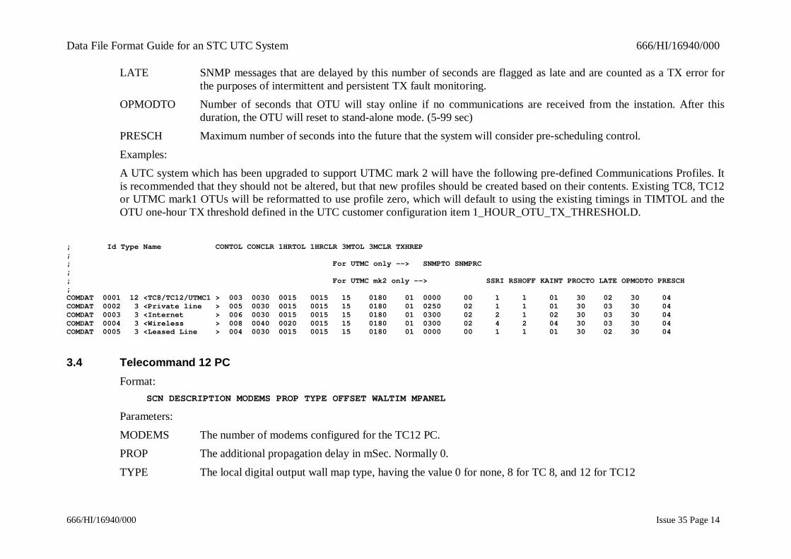
Examples:A UTC system which has been upgraded to support UTMC mark 2 will have the following pre-defined Communications Profiles. Itis recommended that they should not be altered, but that new profiles should be created based on their contents. Existing TC8, TC12or UTMC mark1 OTUs will be reformatted to use profile zero, which will default to using the existing timings in TIMTOL and theOTU one-hour TX threshold defined in the UTC customer configuration item 1_HOUR_OTU_TX_THRESHOLD.
; Id Type Name CONTOL CONCLR 1HRTOL 1HRCLR 3MTOL 3MCLR TXHREP;; For UTMC only --> SNMPTO SNMPRC;; For UTMC mk2 only --> SSRI RSHOFF KAINT PROCTO LATE OPMODTO PRESCH;COMDAT 0001 12 <TC8/TC12/UTMC1 > 003 0030 0015 0015 15 0180 01 0000 00 1 1 01 30 02 30 04COMDAT 0002 3 <Private line > 005 0030 0015 0015 15 0180 01 0250 02 1 1 01 30 03 30 04COMDAT 0003 3 <Internet > 006 0030 0015 0015 15 0180 01 0300 02 2 1 02 30 03 30 04COMDAT 0004 3 <Wireless > 008 0040 0020 0015 15 0180 01 0300 02 4 2 04 30 03 30 04COMDAT 0005 3 <Leased Line > 004 0030 0015 0015 15 0180 01 0000 00 1 1 01 30 02 30 04
3.4 Telecommand 12 PCFormat:
SCN DESCRIPTION MODEMS PROP TYPE OFFSET WALTIM MPANEL
Parameters:
MODEMS The number of modems configured for the TC12 PC.PROP The additional propagation delay in mSec. Normally 0.
TYPE The local digital output wall map type, having the value 0 for none, 8 for TC 8, and 12 for TC12
Data File Format Guide for an STC UTC System 666/HI/16940/000
666/HI/16940/000 Issue 35 Page 15
OFFSET This is the offset within the PC where the digital IO data will be received. Valid entries are 0 or 4 for TC 8 and 1 or2 for TC 12.
WALTIM Specifies if this PC sends the time to the wallmap (0/1)
MPANEL Specifies if this PC drives an Outstation monitor panel (0/1)Examples:
SCN DESCRIPTION MODEMS PROP TYPE OFFSET WALTIM MPANELTC12PC 001 001 <Test PC One > 32 00 12 1 1 1
3.5 ModemsFormat:
MODEM DUPLEX TYPE SPEED
Parameters:
DUPLEX 0 = half duplex, 1 = full duplex mode.TYPE The modem type. 0 = radial, 1 = multipoint
SPEED The transmission rate.Examples:
MODEM DUPLEX TYPE SPEEDMODEM 01 0 1 1200MODEM 02 0 1 1200
3.6 Outstations (TC8)Format:
OSNDAT SCN DESCRIPTION VALID TYPE COMPRO ADDRESS 1 to 4
Parameters:VALID The validity of the OSN. If it is set to 1 the OSN is valid. If it is set to 0 the OSN is not valid and any reply data
from equipment connected to this OSN is not checked and no control data is sent. Normally an OSN which hasbeen set to invalid would not exist and would have no equipment defined for it.
Data File Format Guide for an STC UTC System 666/HI/16940/000
666/HI/16940/000 Issue 35 Page 16
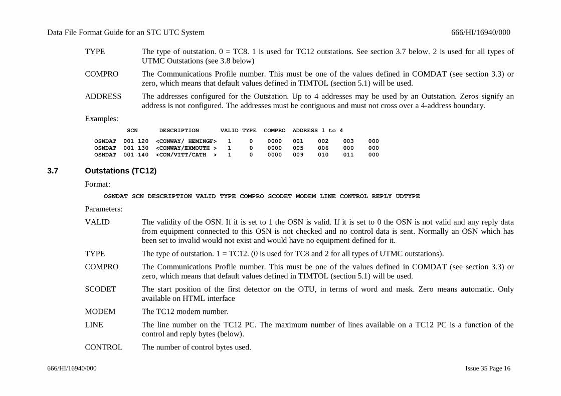
TYPE The type of outstation. 0 = TC8. 1 is used for TC12 outstations. See section 3.7 below. 2 is used for all types ofUTMC Outstations (see 3.8 below)
COMPRO The Communications Profile number. This must be one of the values defined in COMDAT (see section 3.3) orzero, which means that default values defined in TIMTOL (section 5.1) will be used.
ADDRESS The addresses configured for the Outstation. Up to 4 addresses may be used by an Outstation. Zeros signify anaddress is not configured. The addresses must be contiguous and must not cross over a 4-address boundary.
Examples: SCN DESCRIPTION VALID TYPE COMPRO ADDRESS 1 to 4
OSNDAT 001 120 <CONWAY/ HEMINGF> 1 0 0000 001 002 003 000OSNDAT 001 130 <CONWAY/EXMOUTH > 1 0 0000 005 006 000 000OSNDAT 001 140 <CON/VITT/CATH > 1 0 0000 009 010 011 000
3.7 Outstations (TC12)Format:
OSNDAT SCN DESCRIPTION VALID TYPE COMPRO SCODET MODEM LINE CONTROL REPLY UDTYPE
Parameters:VALID The validity of the OSN. If it is set to 1 the OSN is valid. If it is set to 0 the OSN is not valid and any reply data
from equipment connected to this OSN is not checked and no control data is sent. Normally an OSN which hasbeen set to invalid would not exist and would have no equipment defined for it.
TYPE The type of outstation. 1 = TC12. (0 is used for TC8 and 2 for all types of UTMC outstations).COMPRO The Communications Profile number. This must be one of the values defined in COMDAT (see section 3.3) or
zero, which means that default values defined in TIMTOL (section 5.1) will be used.SCODET The start position of the first detector on the OTU, in terms of word and mask. Zero means automatic. Only
available on HTML interfaceMODEM The TC12 modem number.
LINE The line number on the TC12 PC. The maximum number of lines available on a TC12 PC is a function of thecontrol and reply bytes (below).
CONTROL The number of control bytes used.

Data File Format Guide for an STC UTC System 666/HI/16940/000
666/HI/16940/000 Issue 35 Page 17
REPLY The number of reply bytes used.
UDTYPE This indicates if the OTU has the Remote Handset facility and the type of OTU. Possible values and their meaningsare:
0 No remote handset facility1 Free-standing OTU with remote handset facility
2 Integral OTU with remote handset facility3 Integral OTU in an ST800 controller with remote handset facility
Examples: SCN DESCRIPTION VALID TYPE COMPRO SCODET MODEM LINE CONTROL REPLY UDTYPEOSNDAT 051 110 <FIRST TC12 OSN > 1 1 0000 00 0 01 01 2 06 0OSNDAT 051 120 <TEST OSN > 1 1 0000 01 1 01 02 2 06 1OSNDAT 051 130 <OTU D1 > 1 1 0000 00 0 01 03 2 06 2OSNDAT 051 140 <LAST OTU > 1 1 0000 00 0 01 04 3 06 3
3.8 Outstations (UTMC)Format:
OSNDAT SCN DESCRIPTION VALID TYPE COMPRO SCODET HOSTNAME MIB CONTROL REPLY AUTOLAY
Parameters:VALID The validity of the OSN. If it is set to 1 the OSN is valid. If it is set to 0 the OSN is not valid and any reply data
from equipment connected to this OSN is not checked and no control data is sent. Normally an OSN which hasbeen set to invalid would not exist and would have no equipment defined for it.
TYPE The type of outstation 2 = any type of UTMC. (0 is used for TC8 and 1 for TC12 outstations).COMPRO The Communications Profile number. This must be one of the values defined in COMDAT (see section 3.3) or
zero, which means that default values defined in TIMTOL (section 5.1) will be used.SCODET The start position of the first detector on the OTU, in terms of word and mask. Zero means automatic. Only
available on HTML interfaceHOSTNAME The I/P address of the OTUMIB The initial letter of the manufacturer of the UTMC outstation. The options are S for Siemens simple mark 1 UTMC,
P for Peek (or Full) mark 1 UTMC and U for mark 2 UTMC.
Data File Format Guide for an STC UTC System 666/HI/16940/000
666/HI/16940/000 Issue 35 Page 18
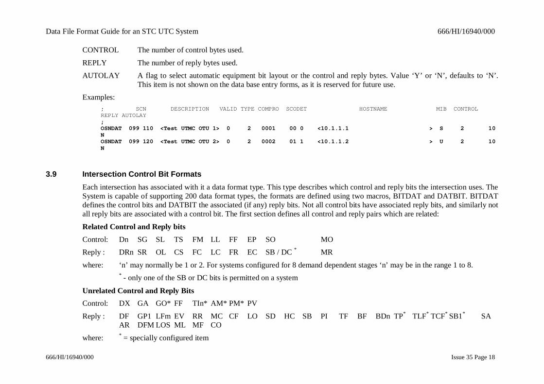
CONTROL The number of control bytes used.
REPLY The number of reply bytes used.AUTOLAY A flag to select automatic equipment bit layout or the control and reply bytes. Value ‘Y’ or ‘N’, defaults to ‘N’.
This item is not shown on the data base entry forms, as it is reserved for future use.Examples:
; SCN DESCRIPTION VALID TYPE COMPRO SCODET HOSTNAME MIB CONTROLREPLY AUTOLAY;OSNDAT 099 110 <Test UTMC OTU 1> 0 2 0001 00 0 <10.1.1.1 > S 2 10NOSNDAT 099 120 <Test UTMC OTU 2> 0 2 0002 01 1 <10.1.1.2 > U 2 10N
3.9 Intersection Control Bit FormatsEach intersection has associated with it a data format type. This type describes which control and reply bits the intersection uses. TheSystem is capable of supporting 200 data format types, the formats are defined using two macros, BITDAT and DATBIT. BITDATdefines the control bits and DATBIT the associated (if any) reply bits. Not all control bits have associated reply bits, and similarly notall reply bits are associated with a control bit. The first section defines all control and reply pairs which are related:
Related Control and Reply bitsControl: Dn SG SL TS FM LL FF EP SO MOReply : DRn SR OL CS FC LC FR EC SB / DC * MR
where: ‘n’ may normally be 1 or 2. For systems configured for 8 demand dependent stages ‘n’ may be in the range 1 to 8.* - only one of the SB or DC bits is permitted on a system
Unrelated Control and Reply BitsControl: DX GA GO* FF TIn* AM* PM* PV
Reply : DF GP1 LFm EV RR MC CF LO SD HC SB PI TF BF BDn TP* TLF* TCF* SB1* SAAR DFM LOS ML MF CO
where: * = specially configured item

Data File Format Guide for an STC UTC System 666/HI/16940/000
666/HI/16940/000 Issue 35 Page 19
‘m’ may be 1 to 3
‘n’ may be 1 to 4Format:
SYSDAT
BITDAT TYPE BIT1 BIT2 BIT3 BIT4 BIT5 ......... BIT32
Parameters:
TYPE The format type number (1-200), the associated reply bits are defined in the DATBIT macro with the same formattype number.
BIT1 to BIT32 This shows the position of the particular control bit relative to the starting point for the format. The starting point isdefined in the ISNDAT macro. The bits are defined using the bit mnemonics shown below. The maximum numberof control bit mnemonics allowed in any format type depends upon the number of control bits allowed on the OTU(i.e. 16 for a free-standing OTU and 24 for an integral OTU). To determine the maximum number of control bitsallowed in any particular format type, the number of intersection stages should be subtracted from the maximumnumber of control bits allowed on the OTU. In the format type, any bits which are not defined will appear as '**'.The user should remember that the display plan monitor (DIPM) screen can only show a maximum of 16 controland reply bits.
Dn Simulate demand for demand-dependent stage n.DX Simulate all demand dependent stages.
SG Synchronise group timer.SO Solar switch override.
SL Switch part-time signals.GA Green wave active.
TS Synchronise the controller's real time clock.FM Assume fallback mode.
LL Inhibit local link.FF Flash amber/red.
Data File Format Guide for an STC UTC System 666/HI/16940/000
666/HI/16940/000 Issue 35 Page 20
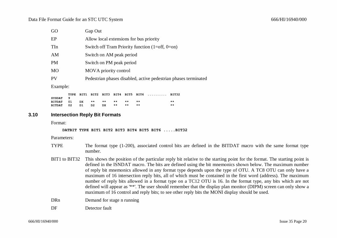
GO Gap Out
EP Allow local extensions for bus priorityTIn Switch off Tram Priority function (1=off, 0=on)
AM Switch on AM peak periodPM Switch on PM peak period
MO MOVA priority controlPV Pedestrian phases disabled, active pedestrian phases terminated
Example:TYPE BIT1 BIT2 BIT3 BIT4 BIT5 BIT6 .......... BIT32
SYSDAT 9BITDAT 01 DX ** ** ** ** ** **BITDAT 02 D1 D2 DX ** ** ** **
3.10 Intersection Reply Bit FormatsFormat:
DATBIT TYPE BIT1 BIT2 BIT3 BIT4 BIT5 BIT6 .....BIT32
Parameters:
TYPE The format type (1-200), associated control bits are defined in the BITDAT macro with the same format typenumber.
BIT1 to BIT32 This shows the position of the particular reply bit relative to the starting point for the format. The starting point isdefined in the ISNDAT macro. The bits are defined using the bit mnemonics shown below. The maximum numberof reply bit mnemonics allowed in any format type depends upon the type of OTU. A TC8 OTU can only have amaximum of 16 intersection reply bits, all of which must be contained in the first word (address). The maximumnumber of reply bits allowed in a format type on a TC12 OTU is 16. In the format type, any bits which are notdefined will appear as '**'. The user should remember that the display plan monitor (DIPM) screen can only show amaximum of 16 control and reply bits; to see other reply bits the MONI display should be used.
DRn Demand for stage n running
DF Detector fault

Data File Format Guide for an STC UTC System 666/HI/16940/000
666/HI/16940/000 Issue 35 Page 21
SR Group timer synchronised
GP1 Group 1 indicationOL Part-time signals switched
LF1 Lamp failure other than LF2LF2 Lamp failure of two reds on the same phase
LF3 Lamp failure defined by userEV Emergency vehicle detected
CS Clocks Synchronised confirmationRR Remote reconnected
MC Manual controlCF 141 controller fault
FC Fallback mode confirmedLC Local link inhibited
LO Lamps offSD Pseudo demand
HC Hurry callSB Solar bright
DC Dimming ConfirmFR Flashing confirmation
PI Pedestrian InhibitTF Test Facility
BF Battery failBDn Bus priority demand bit, where n is in the range 1 to 4
Data File Format Guide for an STC UTC System 666/HI/16940/000
666/HI/16940/000 Issue 35 Page 22
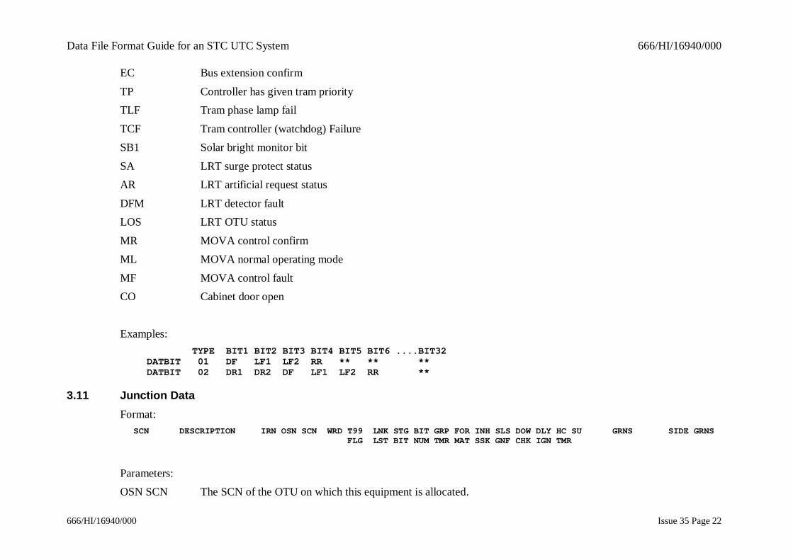
EC Bus extension confirm
TP Controller has given tram priorityTLF Tram phase lamp fail
TCF Tram controller (watchdog) FailureSB1 Solar bright monitor bit
SA LRT surge protect statusAR LRT artificial request status
DFM LRT detector faultLOS LRT OTU status
MR MOVA control confirmML MOVA normal operating mode
MF MOVA control faultCO Cabinet door open
Examples: TYPE BIT1 BIT2 BIT3 BIT4 BIT5 BIT6 ....BIT32DATBIT 01 DF LF1 LF2 RR ** ** **DATBIT 02 DR1 DR2 DF LF1 LF2 RR **
3.11 Junction DataFormat:
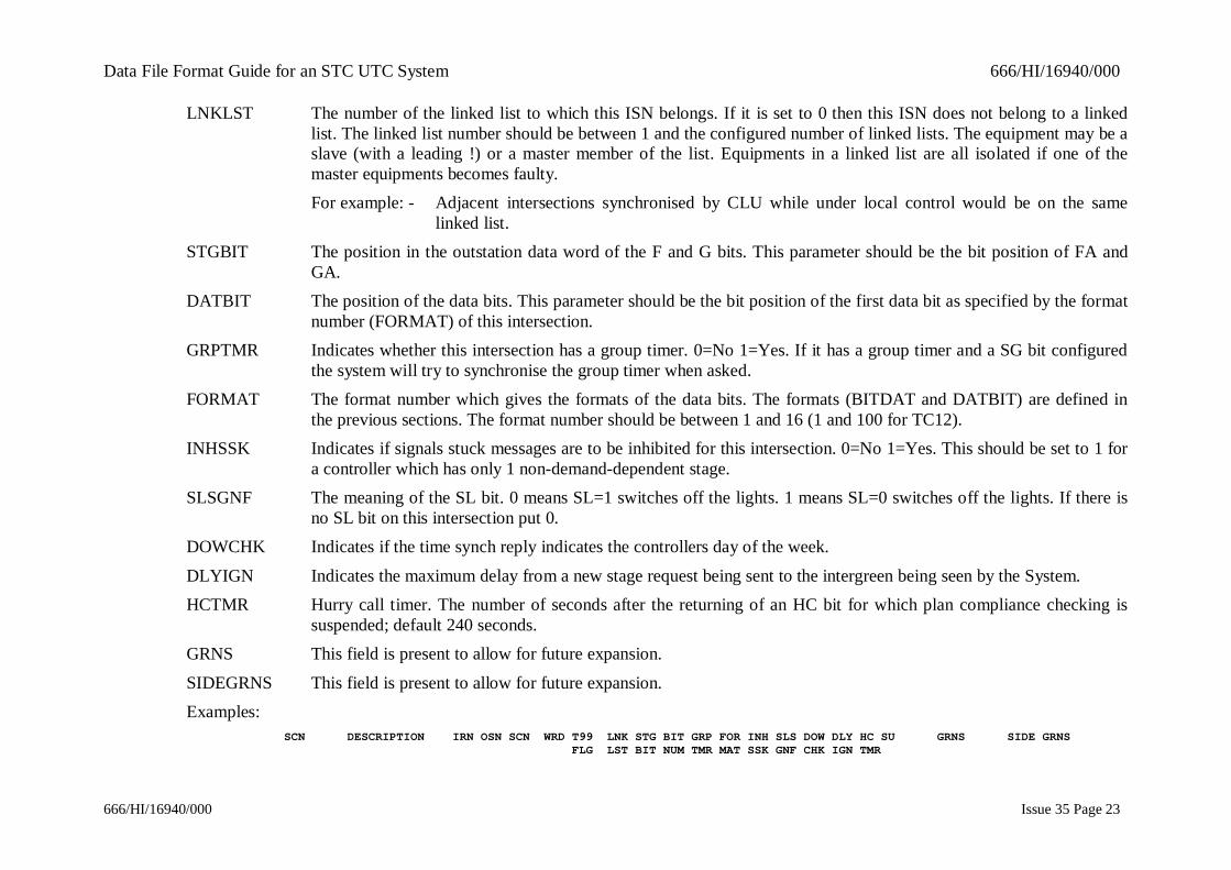
SCN DESCRIPTION IRN OSN SCN WRD T99 LNK STG BIT GRP FOR INH SLS DOW DLY HC SU GRNS SIDE GRNS FLG LST BIT NUM TMR MAT SSK GNF CHK IGN TMR
Parameters:OSN SCN The SCN of the OTU on which this equipment is allocated.
Data File Format Guide for an STC UTC System 666/HI/16940/000
666/HI/16940/000 Issue 35 Page 23
LNKLST The number of the linked list to which this ISN belongs. If it is set to 0 then this ISN does not belong to a linkedlist. The linked list number should be between 1 and the configured number of linked lists. The equipment may be aslave (with a leading !) or a master member of the list. Equipments in a linked list are all isolated if one of themaster equipments becomes faulty.For example: - Adjacent intersections synchronised by CLU while under local control would be on the same
linked list.STGBIT The position in the outstation data word of the F and G bits. This parameter should be the bit position of FA and
GA.DATBIT The position of the data bits. This parameter should be the bit position of the first data bit as specified by the format
number (FORMAT) of this intersection.GRPTMR Indicates whether this intersection has a group timer. 0=No 1=Yes. If it has a group timer and a SG bit configured
the system will try to synchronise the group timer when asked.FORMAT The format number which gives the formats of the data bits. The formats (BITDAT and DATBIT) are defined in
the previous sections. The format number should be between 1 and 16 (1 and 100 for TC12).INHSSK Indicates if signals stuck messages are to be inhibited for this intersection. 0=No 1=Yes. This should be set to 1 for
a controller which has only 1 non-demand-dependent stage.SLSGNF The meaning of the SL bit. 0 means SL=1 switches off the lights. 1 means SL=0 switches off the lights. If there is
no SL bit on this intersection put 0.DOWCHK Indicates if the time synch reply indicates the controllers day of the week.
DLYIGN Indicates the maximum delay from a new stage request being sent to the intergreen being seen by the System.HCTMR Hurry call timer. The number of seconds after the returning of an HC bit for which plan compliance checking is
suspended; default 240 seconds.GRNS This field is present to allow for future expansion.
SIDEGRNS This field is present to allow for future expansion.Examples:
SCN DESCRIPTION IRN OSN SCN WRD T99 LNK STG BIT GRP FOR INH SLS DOW DLY HC SU GRNS SIDE GRNS FLG LST BIT NUM TMR MAT SSK GNF CHK IGN TMR
Data File Format Guide for an STC UTC System 666/HI/16940/000
666/HI/16940/000 Issue 35 Page 24
ISNDAT 001 111 <CONWAY/ARGYLE >008 001 110 0 0 00 00 00 1 012 0 0 0 03 240 0 <0 > <0 >ISNDAT 001 121 <CON/HEMINGFORD >009 001 120 0 0 00 04 00 1 014 0 0 0 4 240 0 <0 > <0 >
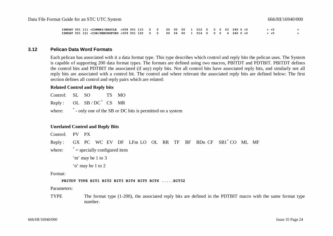
3.12 Pelican Data Word FormatsEach pelican has associated with it a data format type. This type describes which control and reply bits the pelican uses. The Systemis capable of supporting 200 data format types. The formats are defined using two macros, PBITDT and PDTBIT. PBITDT definesthe control bits and PDTBIT the associated (if any) reply bits. Not all control bits have associated reply bits, and similarly not allreply bits are associated with a control bit. The control and where relevant the associated reply bits are defined below: The firstsection defines all control and reply pairs which are related:
Related Control and Reply bitsControl: SL SO TS MOReply : OL SB / DC * CS MR
where: * - only one of the SB or DC bits is permitted on a system
Unrelated Control and Reply BitsControl: PV PX
Reply : GX PC WC EV DF LFm LO OL RR TF BF BDn CF SB1* CO ML MFwhere: * = specially configured item
‘m’ may be 1 to 3‘n’ may be 1 to 2
Format:PBITDT TYPE BIT1 BIT2 BIT3 BIT4 BIT5 BIT6 .....BIT32
Parameters:
TYPE The format type (1-200), the associated reply bits are defined in the PDTBIT macro with the same format typenumber.
Data File Format Guide for an STC UTC System 666/HI/16940/000
666/HI/16940/000 Issue 35 Page 25
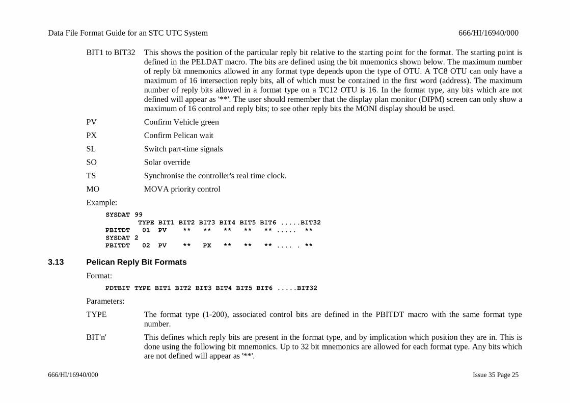
BIT1 to BIT32 This shows the position of the particular reply bit relative to the starting point for the format. The starting point isdefined in the PELDAT macro. The bits are defined using the bit mnemonics shown below. The maximum numberof reply bit mnemonics allowed in any format type depends upon the type of OTU. A TC8 OTU can only have amaximum of 16 intersection reply bits, all of which must be contained in the first word (address). The maximumnumber of reply bits allowed in a format type on a TC12 OTU is 16. In the format type, any bits which are notdefined will appear as '**'. The user should remember that the display plan monitor (DIPM) screen can only show amaximum of 16 control and reply bits; to see other reply bits the MONI display should be used.
PV Confirm Vehicle greenPX Confirm Pelican wait
SL Switch part-time signalsSO Solar override
TS Synchronise the controller's real time clock.MO MOVA priority control
Example:SYSDAT 99 TYPE BIT1 BIT2 BIT3 BIT4 BIT5 BIT6 .....BIT32PBITDT 01 PV ** ** ** ** ** ..... **SYSDAT 2PBITDT 02 PV ** PX ** ** ** .... . **
3.13 Pelican Reply Bit FormatsFormat:
PDTBIT TYPE BIT1 BIT2 BIT3 BIT4 BIT5 BIT6 .....BIT32
Parameters:TYPE The format type (1-200), associated control bits are defined in the PBITDT macro with the same format type
number.BIT'n' This defines which reply bits are present in the format type, and by implication which position they are in. This is
done using the following bit mnemonics. Up to 32 bit mnemonics are allowed for each format type. Any bits whichare not defined will appear as '**'.
Data File Format Guide for an STC UTC System 666/HI/16940/000
666/HI/16940/000 Issue 35 Page 26
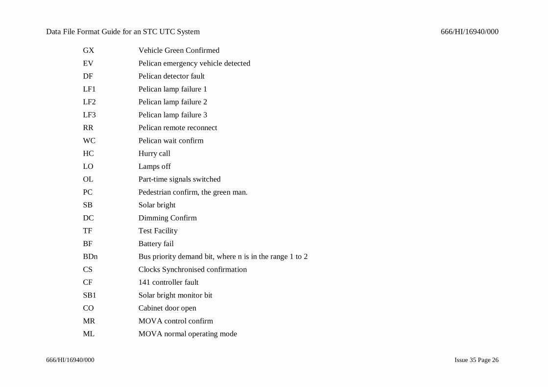
GX Vehicle Green Confirmed
EV Pelican emergency vehicle detectedDF Pelican detector fault
LF1 Pelican lamp failure 1LF2 Pelican lamp failure 2
LF3 Pelican lamp failure 3RR Pelican remote reconnect
WC Pelican wait confirmHC Hurry call
LO Lamps offOL Part-time signals switched
PC Pedestrian confirm, the green man.SB Solar bright
DC Dimming ConfirmTF Test Facility
BF Battery failBDn Bus priority demand bit, where n is in the range 1 to 2
CS Clocks Synchronised confirmationCF 141 controller fault
SB1 Solar bright monitor bitCO Cabinet door open
MR MOVA control confirmML MOVA normal operating mode

Data File Format Guide for an STC UTC System 666/HI/16940/000
666/HI/16940/000 Issue 35 Page 27
MF MOVA control fault
Example:SYSDAT 99 TYPE BIT1 BIT2 BIT3 BIT4 BIT5 BIT6 BIT7 .....BIT32PDTBIT 01 GX ** ** ** ** ** .... **
SYSDAT 01PDTBIT 02 GX EV DF RR ** ** ..... **

Data File Format Guide for an STC UTC System 666/HI/16940/000
666/HI/16940/000 Issue 35 Page 28
3.14 Pelican DataFormat:
PELDAT SCN DESCRIPTION IRN OSN SCN WORD DUO BITNUM NOTGX TYPE LNKLST GX UPRNGX PEDGRN UPEDGN
Parameters:BITNUM The bit position of the first pelican data bit.
OSN SCN The SCN of the OTU on which this equipment is allocated.NOTGX The time for which the pelican does not return GX when it goes to the pedestrian stage.
TYPE The format type of the pelican. The format types are defined below.LNKLST The number of the linked list to which this pelican belongs. If it is set to 0 then this pelican does not belong to a
linked list. The linked list number should be between 1 and the configured number of linked lists. The equipmentmay be a slave (with a leading !) or a master member of the list. Equipments in a linked list are all isolated if one ofthe master equipments becomes faulty.For example: - Adjacent intersections synchronised by CLU while under local control would be on the same linked
list.GX The minimum time for which the pelican will show green to vehicles. This value is used (with the NOTGX time) by
the plan preparation program to check the minimum allowable cycle time.UPRNGX Highest not GX time that this pelican will report. This will normally only differ from not GX when VA mode is in
use.PEDGRN The minimum time the pedestrian green man is shown.
UPEDGN The maximum time the pedestrian green man is shown.Examples: SCN DESCRIPTION IRN OSN SCN WORD DUO BITNUM NOTGX TYPE LNKLST GX UPRNGX PEDGRN UPEDGNPELDAT 001 111 <Bridge Station> 001 001 110 2 0 12 020 001 00 007 010 000 000PELDAT 001 123 <CONWAY/CAMDEN > 002 001 111 1 0 08 029 003 00 007 010 000 000

Data File Format Guide for an STC UTC System 666/HI/16940/000
666/HI/16940/000 Issue 35 Page 29
3.15 Timetable Plans OnlyFormat:
PLNDAT NUMBER VALUE
Parameters:NUMBER The plan number.
VALUE 0 - means the plan is not restricted.1 - means the plan may only be called for ALL sub-areas from a timetable i.e. not from the operator PLANcommand.
Examples:NUMBER VALUEPLNDAT 3 0 ;no restrictionPLNDAT 4 1 ;all sub-areas may only be called from a timetable.
3.16 Special Facility DataFormat:
SPCDAT SCN DESCRIPTION IRN OSN SCN WORD DUO BITNUM SPCCON RRBIT TYPE LN
Parameters:
BITNUM The bit position of the first Special Facility data bit.SPCCON Indicates whether the Special Facility has a confirm bit. Set to 1 if the confirm bit is present, or 0 for no confirm bit
(green wave special facility).RRBIT Indicates whether the Special Facility has a Remote Reconnect bit. Set to 1 if present, or 0 if not.
TYPE "!" is normal, "2" means it is controlled by plan.LN "!" means a slave in the associated linked list. No "!" means a master.
Examples: SCN DESCRIPTION IRN OSN SCN WORD DUO BITNUM SPCCON RRBIT TYPE LNKLSTSPCDAT 001 126 <FIFTH SF > 005 001 120 1 0 13 0 0 1 !10SPCDAT 005 127 <THIRD SF > 006 005 110 4 0 00 1 0 2 12

Data File Format Guide for an STC UTC System 666/HI/16940/000
666/HI/16940/000 Issue 35 Page 30
3.17 Special Facility Enable by Plan DataFormat:
PLNSPC SPCIRN EQUIPMENT FIXED-TIME PLAN LIST SCOOT TPLAN LIST
Parameters :SPCIRN Special facility IRN.
EQUIPMENT Junction SCN to be used to determine the correctplan.
FIXED-TIME PLANLIST
List of fixed time plans for which this special facilityis on.
SCOOT TPLAN LIST List of SCOOT stage translation plans for which thisspecial facility is on
Example: SPCIRN EQUIPMENT FIXED-TIME PLAN LIST SCOOT TPLAN LIST PLNSPC 002 J 003 111 <1 ><1 >
3.18 Queue Detector DataFormat:
QUEDAT SCN DESCRIPTION IRN OSN SCN WORD DUO BITNUM GROUP CANVAL
Parameters:BITNUM The number of the first data bit on the OTU.
GROUP The group number for this queue detector.A 'queue formed' will only be reported when all the queue detectors in a queue group have detected a queue.Similarly, only when all the detectors in a queue group have detected that the queues have cleared, will a 'queuecleared' be reported.
CANVAL The time in seconds between the queue clearing and the clearance being reported.Range: 2 - 127.
Data File Format Guide for an STC UTC System 666/HI/16940/000
666/HI/16940/000 Issue 35 Page 31
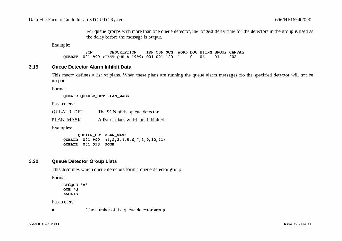
For queue groups with more than one queue detector, the longest delay time for the detectors in the group is used asthe delay before the message is output.
Example: SCN DESCRIPTION IRN OSN SCN WORD DUO BITNM GROUP CANVALQUEDAT 001 999 <TEST QUE A 1999> 001 001 120 1 0 06 01 002
3.19 Queue Detector Alarm Inhibit DataThis macro defines a list of plans. When these plans are running the queue alarm messages fro the specified detector will not beoutput.
Format :QUEALR QUEALR_DET PLAN_MASK
Parameters:
QUEALR_DET The SCN of the queue detector.PLAN_MASK A list of plans which are inhibited.
Examples: QUEALR_DET PLAN_MASKQUEALR 001 999 <1,2,3,4,5,6,7,8,9,10,11>QUEALR 001 998 NONE
3.20 Queue Detector Group ListsThis describes which queue detectors form a queue detector group.
Format:BEGQUE 'n'QUE 'd'ENDLIS
Parameters:
n The number of the queue detector group.
Data File Format Guide for an STC UTC System 666/HI/16940/000
666/HI/16940/000 Issue 35 Page 32
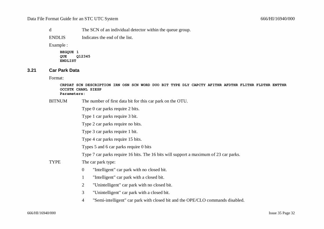
d The SCN of an individual detector within the queue group.
ENDLIS Indicates the end of the list.Example :
BEGQUE 1QUE Q12345ENDLIST
3.21 Car Park DataFormat:
CRPDAT SCN DESCRIPTION IRN OSN SCN WORD DUO BIT TYPE DLY CAPCTY AFITHR AFDTHR FLITHR FLDTHR ENTTHROCCSTK CHANL SIESPParameters:
BITNUM The number of first data bit for this car park on the OTU.
Type 0 car parks require 2 bits.Type 1 car parks require 3 bit.
Type 2 car parks require no bits.Type 3 car parks require 1 bit.
Type 4 car parks require 15 bits.Types 5 and 6 car parks require 0 bits
Type 7 car parks require 16 bits. The 16 bits will support a maximum of 23 car parks.TYPE The car park type:
0 "Intelligent" car park with no closed bit.1 "Intelligent" car park with a closed bit.
2 "Unintelligent" car park with no closed bit.3 "Unintelligent" car park with a closed bit.
4 "Semi-intelligent" car park with closed bit and the OPE/CLO commands disabled.

Data File Format Guide for an STC UTC System 666/HI/16940/000
666/HI/16940/000 Issue 35 Page 33
5 Pay and Display Car Park Management system
6 Pay on Foot Car Park Management system7 Car park system connected to TC12 OTU handset port, e.g. Alfia
where:Intelligent car parks are ones which return their status (full, almost full, or spaces)
Semi-intelligent car parks are ones which keep a running count of the number of cars present.Unintelligent car parks are ones which only return the entry or exit of a vehicle.
DLY The car park change down state delay time. Delay (in minutes) from a change of car park state before it will changeto a lower state (e.g. from FULL to ALMOST FULL).
CAPCTY The capacity of the car park ( For "unintelligent" car parks only).AFITHR Almost full (increasing) threshold. The value at which the car park status will change from SPACES to ALMOST
FULL (for "unintelligent" car parks only). If this value is 0, then the ALMOST FULL state for the car park will besuppressed.
AFDTHR Almost full (decreasing) threshold. The value at which the car park status will change from ALMOST FULL toSPACES (for "unintelligent" car parks only). If this value is 0, then the ALMOST FULL state for the car park willbe suppressed.
FLITHR Full (increasing) threshold. The value at which the car park status will change from ALMOST FULL to FULL (for"unintelligent" car parks only).
FLDTHR Full (decreasing) threshold. The value at which the car park status will change from FULL to ALMOST FULL (for"unintelligent" car parks only).
ENTTHR Entrance sign threshold. The value at which an entrance sign will change from SPACES to FULL (for"unintelligent" car parks only). If omitted, FLITHR is used.
OCCSTK Occupancy Stuck timer. The length of time to elapse until the system will consider the occupancy to have stuckRange (0-24 hours)
CHANL OTU Serial Car Park interface channel number (range 1-23).
SIESP Send spaces to SieSpace? (0/1)
Data File Format Guide for an STC UTC System 666/HI/16940/000
666/HI/16940/000 Issue 35 Page 34
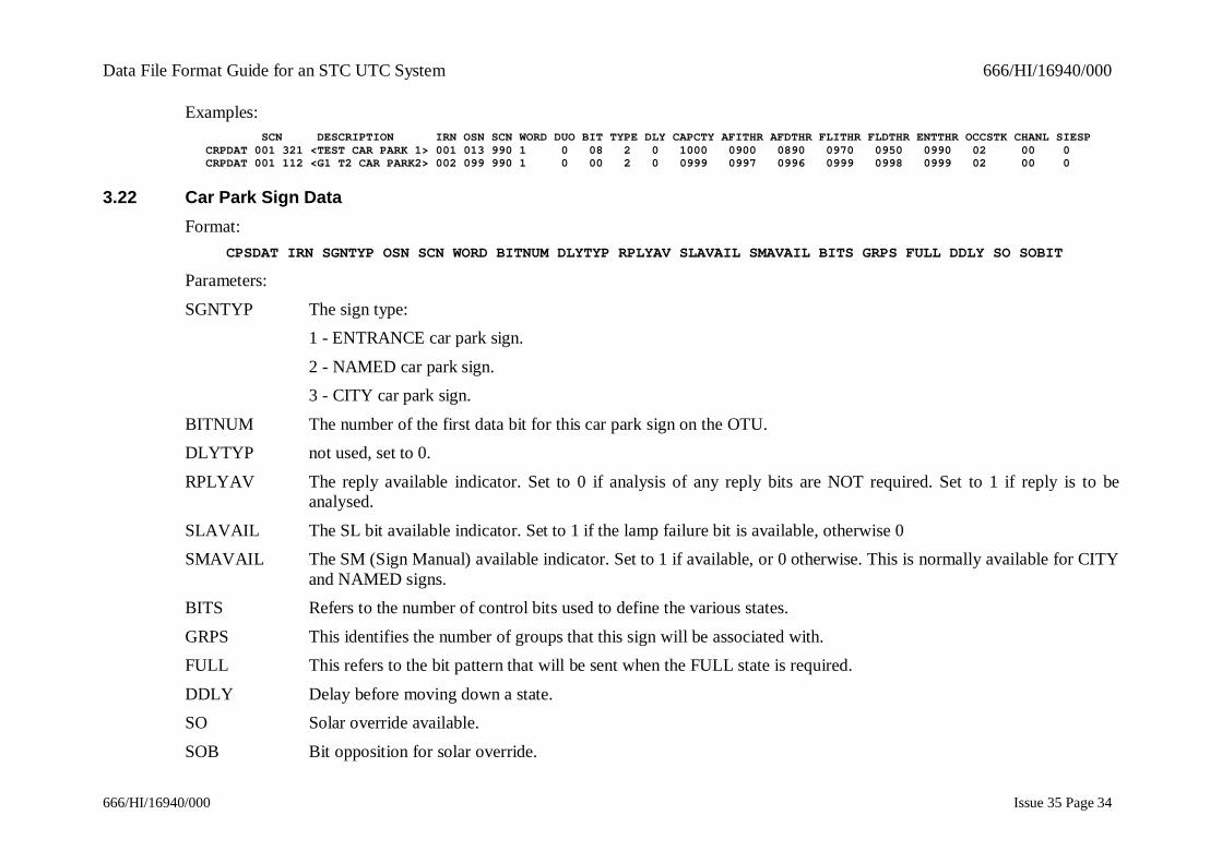
Examples: SCN DESCRIPTION IRN OSN SCN WORD DUO BIT TYPE DLY CAPCTY AFITHR AFDTHR FLITHR FLDTHR ENTTHR OCCSTK CHANL SIESPCRPDAT 001 321 <TEST CAR PARK 1> 001 013 990 1 0 08 2 0 1000 0900 0890 0970 0950 0990 02 00 0CRPDAT 001 112 <G1 T2 CAR PARK2> 002 099 990 1 0 00 2 0 0999 0997 0996 0999 0998 0999 02 00 0
3.22 Car Park Sign DataFormat:
CPSDAT IRN SGNTYP OSN SCN WORD BITNUM DLYTYP RPLYAV SLAVAIL SMAVAIL BITS GRPS FULL DDLY SO SOBIT
Parameters:
SGNTYP The sign type:1 - ENTRANCE car park sign.
2 - NAMED car park sign.3 - CITY car park sign.
BITNUM The number of the first data bit for this car park sign on the OTU.DLYTYP not used, set to 0.
RPLYAV The reply available indicator. Set to 0 if analysis of any reply bits are NOT required. Set to 1 if reply is to beanalysed.
SLAVAIL The SL bit available indicator. Set to 1 if the lamp failure bit is available, otherwise 0SMAVAIL The SM (Sign Manual) available indicator. Set to 1 if available, or 0 otherwise. This is normally available for CITY
and NAMED signs.BITS Refers to the number of control bits used to define the various states.
GRPS This identifies the number of groups that this sign will be associated with.FULL This refers to the bit pattern that will be sent when the FULL state is required.
DDLY Delay before moving down a state.SO Solar override available.
SOB Bit opposition for solar override.
Data File Format Guide for an STC UTC System 666/HI/16940/000
666/HI/16940/000 Issue 35 Page 35
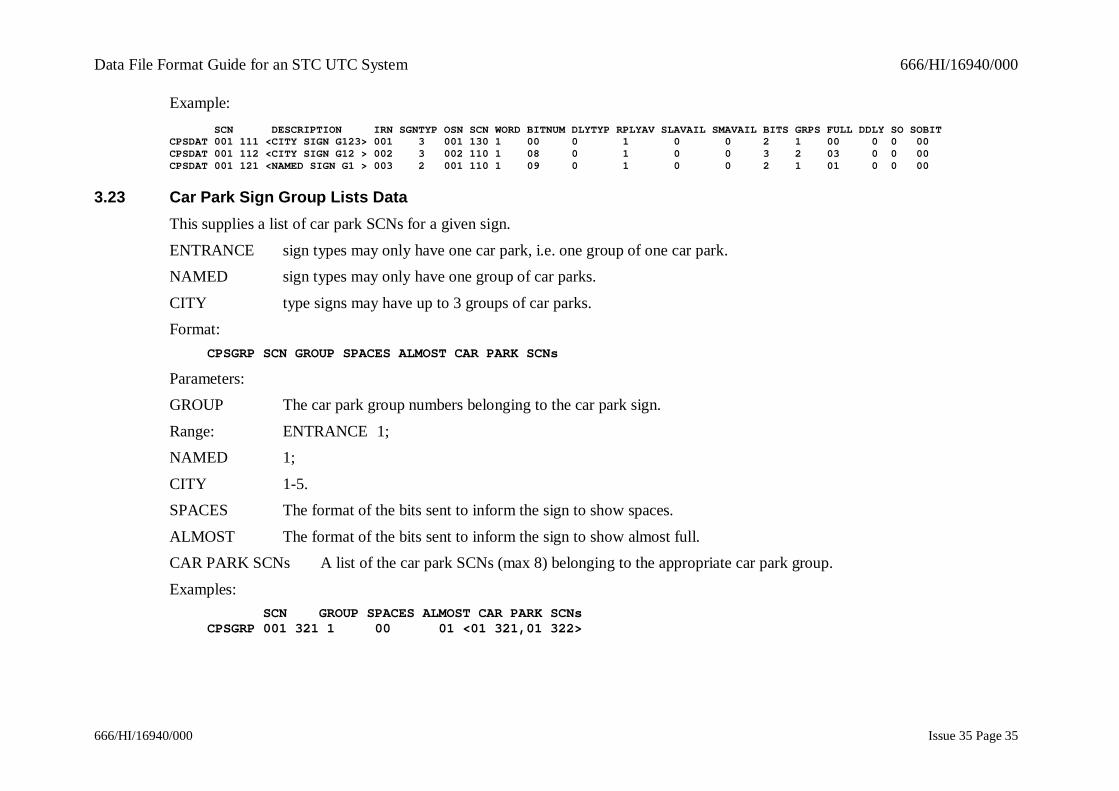
Example: SCN DESCRIPTION IRN SGNTYP OSN SCN WORD BITNUM DLYTYP RPLYAV SLAVAIL SMAVAIL BITS GRPS FULL DDLY SO SOBITCPSDAT 001 111 <CITY SIGN G123> 001 3 001 130 1 00 0 1 0 0 2 1 00 0 0 00CPSDAT 001 112 <CITY SIGN G12 > 002 3 002 110 1 08 0 1 0 0 3 2 03 0 0 00CPSDAT 001 121 <NAMED SIGN G1 > 003 2 001 110 1 09 0 1 0 0 2 1 01 0 0 00
3.23 Car Park Sign Group Lists DataThis supplies a list of car park SCNs for a given sign.
ENTRANCE sign types may only have one car park, i.e. one group of one car park.NAMED sign types may only have one group of car parks.
CITY type signs may have up to 3 groups of car parks.Format:
CPSGRP SCN GROUP SPACES ALMOST CAR PARK SCNs
Parameters:GROUP The car park group numbers belonging to the car park sign.
Range: ENTRANCE 1;NAMED 1;
CITY 1-5.SPACES The format of the bits sent to inform the sign to show spaces.
ALMOST The format of the bits sent to inform the sign to show almost full.CAR PARK SCNs A list of the car park SCNs (max 8) belonging to the appropriate car park group.
Examples: SCN GROUP SPACES ALMOST CAR PARK SCNsCPSGRP 001 321 1 00 01 <01 321,01 322>

Data File Format Guide for an STC UTC System 666/HI/16940/000
666/HI/16940/000 Issue 35 Page 36
3.24 Car Park Pay and Display Group Lists DataFormat:
PADDATSCN MACHINE IDENTS
Parameters:MACHINE IDENTS The identities of the pay and display machines which are sited in a car park
Example: SCN MACHINE IDENTSPADDAT 007 911 <0422,0423,0424,0425,0421,0259>PADDAT 007 911 <0156,0271,0272>PADDAT 007 912 <0255,0164,0252,0253>
3.25 Count Detector DataFormat:
CNTDATSCN DESCRIPTION IRN OSN SCN WORD DUO SCALE MINVAL ENTEXT CRPNUM DFPOS VLPRES OMUSCN OMUDET OMUPOS BITNUM FORMAT MINTHR
Parameters:
BITNUM The number of the first data bit for this detector on the OTU.SCALE The number of vehicles represented by one change of state of the least significant count bit returned by the detector.
If the scale factor has a value of 0 the count is only incremented when the VC bit changes from 0 to 1 (leading edgecount).
FORMAT The count detector format type. These are as follows :-
FORMAT First Second Third FourthBit Bit Bit Bit
0 Pseudo detector (SCOOT loop)1 VC DF2 VC1 VC2 DF3 VC VO DF4 VC1 VC2 VO DF5 For RMS data from OMUs
Data File Format Guide for an STC UTC System 666/HI/16940/000
666/HI/16940/000 Issue 35 Page 37
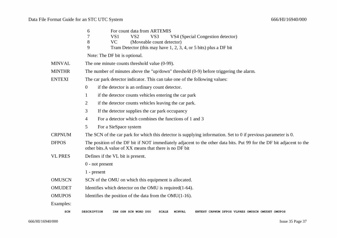
6 For count data from ARTEMIS7 VS1 VS2 VS3 VS4 (Special Congestion detector)8 VC (Moveable count detector)9 Tram Detector (this may have 1, 2, 3, 4, or 5 bits) plus a DF bitNote: The DF bit is optional.
MINVAL The one minute counts threshold value (0-99).MINTHR The number of minutes above the "up/down" threshold (0-9) before triggering the alarm.
ENTEXI The car park detector indicator. This can take one of the following values:0 if the detector is an ordinary count detector.
1 if the detector counts vehicles entering the car park2 if the detector counts vehicles leaving the car park.
3 If the detector supplies the car park occupancy4 For a detector which combines the functions of 1 and 3
5 For a SieSpace systemCRPNUM The SCN of the car park for which this detector is supplying information. Set to 0 if previous parameter is 0.
DFPOS The position of the DF bit if NOT immediately adjacent to the other data bits. Put 99 for the DF bit adjacent to theother bits.A value of XX means that there is no DF bit
VL PRES Defines if the VL bit is present.0 - not present
1 - presentOMUSCN SCN of the OMU on which this equipment is allocated.
OMUDET Identifies which detector on the OMU is required(1-64).OMUPOS Identifies the position of the data from the OMU(1-16).
Examples: SCN DESCRIPTION IRN OSN SCN WORD DUO SCALE MINVAL ENTEXT CRPNUM DFPOS VLPRES OMUSCN OMUDET OMUPOS

Data File Format Guide for an STC UTC System 666/HI/16940/000
666/HI/16940/000 Issue 35 Page 38
BITNUM FORMAT MINTHRCNTDAT 001 116 <CP 1 ENTRANCE > 001 001 110 1 0 07 008 01 99 9 0 054 321 99 0 000 000 00 00CNTDAT 001 117 <CP 1 EXIT > 002 001 110 1 0 10 008 03 00 9 0 054 321 99 0 000 000 00 00
3.26 Occupancy DataFormat:
OCCDAT SCN DESCRIPTION IRN UPTHRES DOWNTHRES SMOOTH
Parameters:UPTHRES the value which the averaged occupancy must reach in order to set the occupancy detector 'on'.
Range: 0 - 99 %DOWNTHRES the value which the averaged occupancy must reach in order to set the occupancy detector 'off' again.
Range: 0 - UPTHRES.SMOOTH the percentage of the current occupancy and 100% of the averaged occupancy used to calculate the new average
occupancy.Range: 0 - 99 %
Example: SCN DESCRIPTION IRN UPTHRES DOWNTHRES SMOOTHOCCDAT 002 136 <TEST OCCUPANCY 1> 014 10 05 00
3.27 Car Park Queueing TimeFormat:
QUETIM SCN CRPTYP %OCC QUETIM %OCC QUETIM %OCC QUETIM %OCC QUETIM
Parameters:
CRPTYP Type of the car park%OCC One of 4 percentage occupancies below which QUETIM will be used as the queuing time for the car park.
QUETIM Queuing time in minutes.
Data File Format Guide for an STC UTC System 666/HI/16940/000
666/HI/16940/000 Issue 35 Page 39
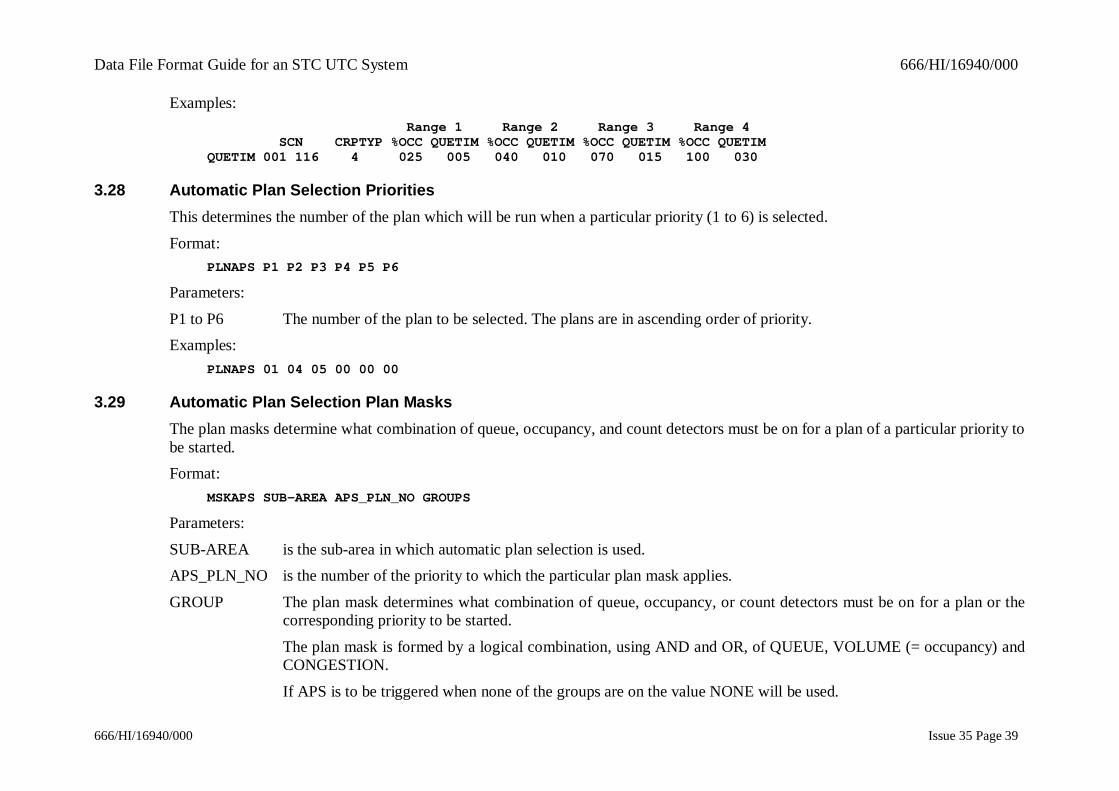
Examples: Range 1 Range 2 Range 3 Range 4 SCN CRPTYP %OCC QUETIM %OCC QUETIM %OCC QUETIM %OCC QUETIMQUETIM 001 116 4 025 005 040 010 070 015 100 030
3.28 Automatic Plan Selection PrioritiesThis determines the number of the plan which will be run when a particular priority (1 to 6) is selected.
Format:PLNAPS P1 P2 P3 P4 P5 P6
Parameters:
P1 to P6 The number of the plan to be selected. The plans are in ascending order of priority.Examples:
PLNAPS 01 04 05 00 00 00
3.29 Automatic Plan Selection Plan MasksThe plan masks determine what combination of queue, occupancy, and count detectors must be on for a plan of a particular priority tobe started.Format:
MSKAPS SUB-AREA APS_PLN_NO GROUPS
Parameters:
SUB-AREA is the sub-area in which automatic plan selection is used.APS_PLN_NO is the number of the priority to which the particular plan mask applies.
GROUP The plan mask determines what combination of queue, occupancy, or count detectors must be on for a plan or thecorresponding priority to be started.
The plan mask is formed by a logical combination, using AND and OR, of QUEUE, VOLUME (= occupancy) andCONGESTION.
If APS is to be triggered when none of the groups are on the value NONE will be used.
Data File Format Guide for an STC UTC System 666/HI/16940/000
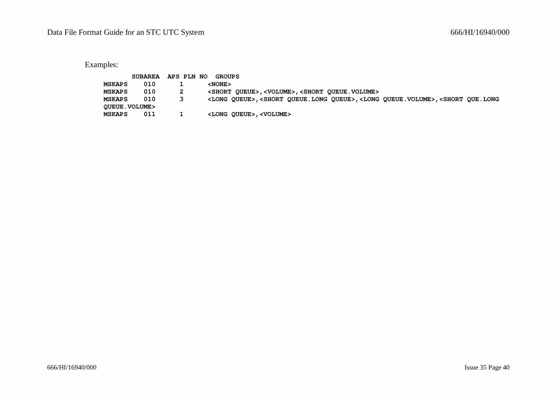
666/HI/16940/000 Issue 35 Page 40
Examples: SUBAREA APS PLN NO GROUPSMSKAPS 010 1 <NONE>MSKAPS 010 2 <SHORT QUEUE>,<VOLUME>,<SHORT QUEUE.VOLUME>MSKAPS 010 3 <LONG QUEUE>,<SHORT QUEUE.LONG QUEUE>,<LONG QUEUE.VOLUME>,<SHORT QUE.LONGQUEUE.VOLUME>MSKAPS 011 1 <LONG QUEUE>,<VOLUME>

Data File Format Guide for an STC UTC System 666/HI/16940/000
666/HI/16940/000 Issue 35 Page 41
3.30 Long Queue Groups APSSets up the long queue groups for use in automatic plan selection.
Format:LNQAPS SUBAREA TRIGGER ReRUN TIME DETECTORS
Parameters:
SUBAREA Sub-area number.TRIGGER Has values 0/1 where
0 = All detectors in a group have to be on before the group is on;1 = If one of the detectors in the group is on then the group is on.
ReRUN TIME The APS re-run interval.DETECTORS The list of SCNs of the appropriate detector type.
Example: SUBAREA TRIGGER ReRUN TIME DETECTORSLNQAPS 010 1 015 000 000 000 000 000 000 000 000LNQAPS 011 1 015 010 361 000 000 000 000 000 000
3.31 Short Queue Groups APSSets up the short queue groups for use in automatic plan selection.
Format:SHQAPS SUBAREA TRIGGER ReRUN TIME DETECTORS
Parameters:
SUBAREA Sub-area number.TRIGGER Has values 0/1 where
0 = All detectors in a group have to be on before the group is on;1 = If one of the detectors in the group is on then the group is on.

Data File Format Guide for an STC UTC System 666/HI/16940/000
666/HI/16940/000 Issue 35 Page 42
ReRUN TIME The APS re-run interval.
DETECTORS The list of SCNs of the appropriate detector type.Example:
SUBAREA TRIGGER ReRUN TIME DETECTORSSHQAPS 010 1 015 001 999 000 000 000 000 000 000SHQAPS 010 0 015 010 361 000 000 000 000 000 000
3.32 APS Occupancy GroupsSets up the occupancy (congestion) groups for use in automatic plan selection.
Format:CONAPS SUBAREA TRIGGER ReRUN TIME DETECTORS
Parameters:
SUBAREA Sub-area number.TRIGGER Has values 0/1 where
0 = All detectors in a group have to be on before the group is on;1 = If one of the detectors in the group is on then the group is on.
ReRUN TIME The APS re-run interval.DETECTORS The list of SCNs of the appropriate detector type.
Example: SUBAREA TRIGGER ReRUN TIME DETECTORSCONAPS 010 1 015 002 141 000 000 000 000 000 000CONAPS 011 1 015 001 999 000 000 000 000 000 000
3.33 APS Volume GroupsSets up the volume (flow) groups.
Data File Format Guide for an STC UTC System 666/HI/16940/000
666/HI/16940/000 Issue 35 Page 43
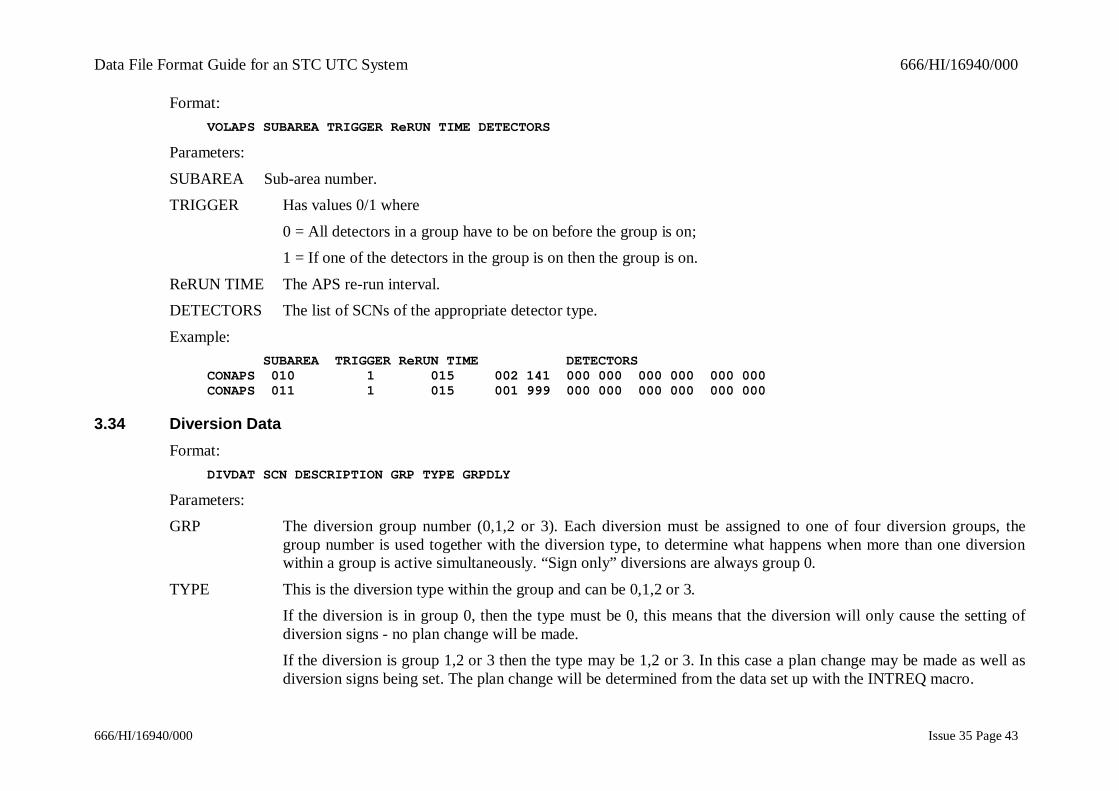
Format:VOLAPS SUBAREA TRIGGER ReRUN TIME DETECTORS
Parameters:
SUBAREA Sub-area number.TRIGGER Has values 0/1 where
0 = All detectors in a group have to be on before the group is on;1 = If one of the detectors in the group is on then the group is on.
ReRUN TIME The APS re-run interval.DETECTORS The list of SCNs of the appropriate detector type.
Example: SUBAREA TRIGGER ReRUN TIME DETECTORSCONAPS 010 1 015 002 141 000 000 000 000 000 000CONAPS 011 1 015 001 999 000 000 000 000 000 000
3.34 Diversion DataFormat:
DIVDAT SCN DESCRIPTION GRP TYPE GRPDLY
Parameters:GRP The diversion group number (0,1,2 or 3). Each diversion must be assigned to one of four diversion groups, the
group number is used together with the diversion type, to determine what happens when more than one diversionwithin a group is active simultaneously. “Sign only” diversions are always group 0.
TYPE This is the diversion type within the group and can be 0,1,2 or 3.If the diversion is in group 0, then the type must be 0, this means that the diversion will only cause the setting ofdiversion signs - no plan change will be made.If the diversion is group 1,2 or 3 then the type may be 1,2 or 3. In this case a plan change may be made as well asdiversion signs being set. The plan change will be determined from the data set up with the INTREQ macro.
Data File Format Guide for an STC UTC System 666/HI/16940/000
666/HI/16940/000 Issue 35 Page 44
Within a group there may only be one diversion of type 1, one diversion of type 2 and one diversion of type 3.There may be more than one diversion of type 0.
GRPDLY This defines the time which will elapse before a diversion sign is switched on after the relevant command has beenimplemented. It may have a value in the range 0-15 in half minutes, i.e. 0-7.5 minutes.
Examples: SCN DESCRIPTION GRP TYPE GRPDLYDIVDAT 002 998 <TEST DIV A 1999> 0 0 01DIVDAT 002 999 <TEST DIV A 1999> 0 0 02
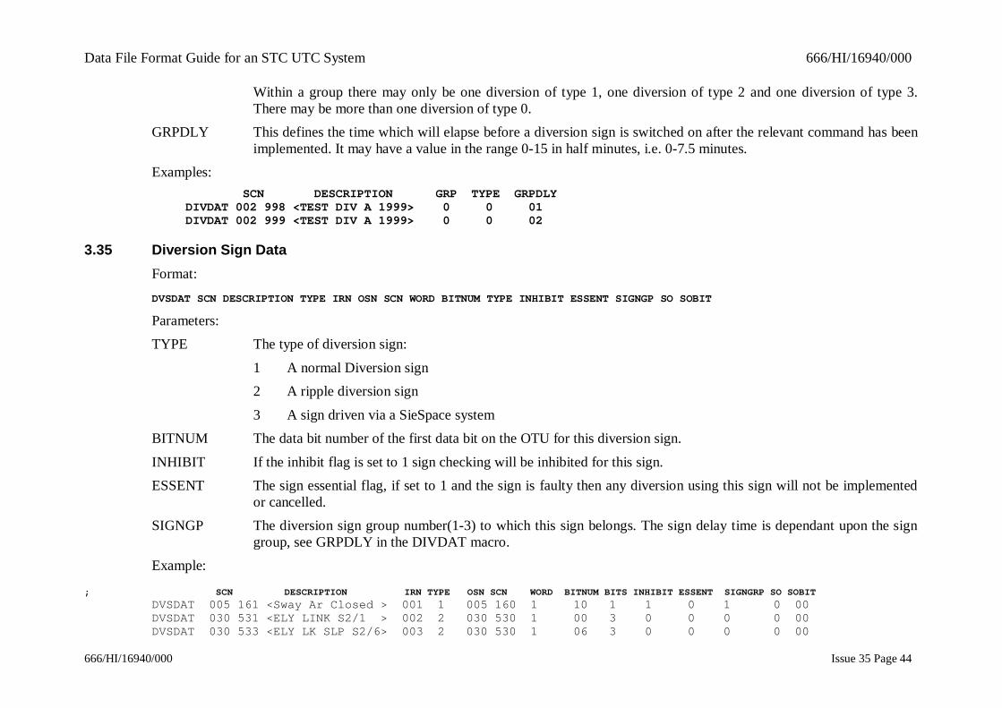
3.35 Diversion Sign DataFormat:DVSDAT SCN DESCRIPTION TYPE IRN OSN SCN WORD BITNUM TYPE INHIBIT ESSENT SIGNGP SO SOBIT
Parameters:TYPE The type of diversion sign:
1 A normal Diversion sign2 A ripple diversion sign
3 A sign driven via a SieSpace systemBITNUM The data bit number of the first data bit on the OTU for this diversion sign.
INHIBIT If the inhibit flag is set to 1 sign checking will be inhibited for this sign.ESSENT The sign essential flag, if set to 1 and the sign is faulty then any diversion using this sign will not be implemented
or cancelled.SIGNGP The diversion sign group number(1-3) to which this sign belongs. The sign delay time is dependant upon the sign
group, see GRPDLY in the DIVDAT macro.Example:
; SCN DESCRIPTION IRN TYPE OSN SCN WORD BITNUM BITS INHIBIT ESSENT SIGNGRP SO SOBITDVSDAT 005 161 <Sway Ar Closed > 001 1 005 160 1 10 1 1 0 1 0 00DVSDAT 030 531 <ELY LINK S2/1 > 002 2 030 530 1 00 3 0 0 0 0 00DVSDAT 030 533 <ELY LK SLP S2/6> 003 2 030 530 1 06 3 0 0 0 0 00
Data File Format Guide for an STC UTC System 666/HI/16940/000
666/HI/16940/000 Issue 35 Page 45
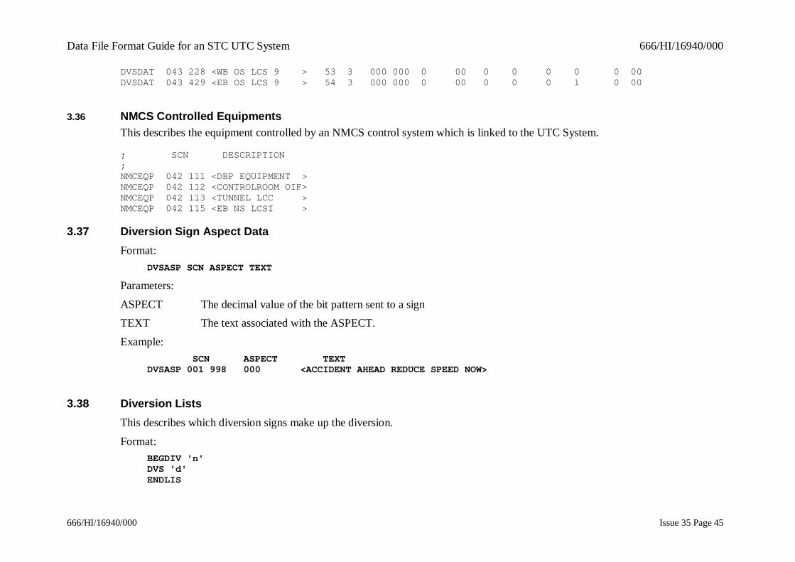
DVSDAT 043 228 <WB OS LCS 9 > 53 3 000 000 0 00 0 0 0 0 0 00DVSDAT 043 429 <EB OS LCS 9 > 54 3 000 000 0 00 0 0 0 1 0 00
3.36 NMCS Controlled EquipmentsThis describes the equipment controlled by an NMCS control system which is linked to the UTC System.
; SCN DESCRIPTION;NMCEQP 042 111 <DBP EQUIPMENT >NMCEQP 042 112 <CONTROLROOM OIF>NMCEQP 042 113 <TUNNEL LCC >NMCEQP 042 115 <EB NS LCSI >
3.37 Diversion Sign Aspect DataFormat:
DVSASP SCN ASPECT TEXT
Parameters:
ASPECT The decimal value of the bit pattern sent to a signTEXT The text associated with the ASPECT.
Example: SCN ASPECT TEXTDVSASP 001 998 000 <ACCIDENT AHEAD REDUCE SPEED NOW>
3.38 Diversion ListsThis describes which diversion signs make up the diversion.
Format:BEGDIV 'n'DVS 'd'ENDLIS
Data File Format Guide for an STC UTC System 666/HI/16940/000
666/HI/16940/000 Issue 35 Page 46
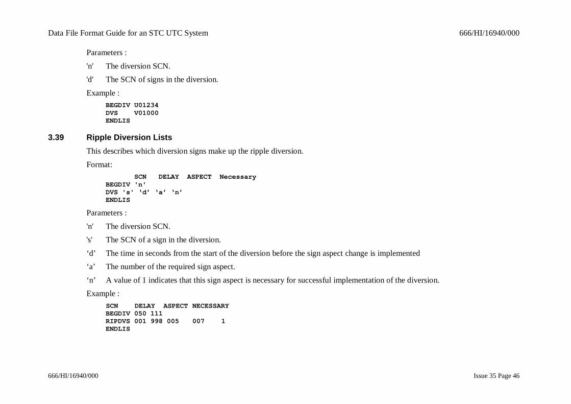
Parameters :
'n' The diversion SCN.'d' The SCN of signs in the diversion.
Example :BEGDIV U01234DVS V01000ENDLIS
3.39 Ripple Diversion ListsThis describes which diversion signs make up the ripple diversion.
Format: SCN DELAY ASPECT NecessaryBEGDIV 'n'DVS 's' ‘d’ ‘a’ ‘n’ENDLIS
Parameters :
'n' The diversion SCN.'s' The SCN of a sign in the diversion.
‘d’ The time in seconds from the start of the diversion before the sign aspect change is implemented‘a’ The number of the required sign aspect.
‘n’ A value of 1 indicates that this sign aspect is necessary for successful implementation of the diversion.Example :
SCN DELAY ASPECT NECESSARYBEGDIV 050 111RIPDVS 001 998 005 007 1ENDLIS
Data File Format Guide for an STC UTC System 666/HI/16940/000
666/HI/16940/000 Issue 35 Page 47
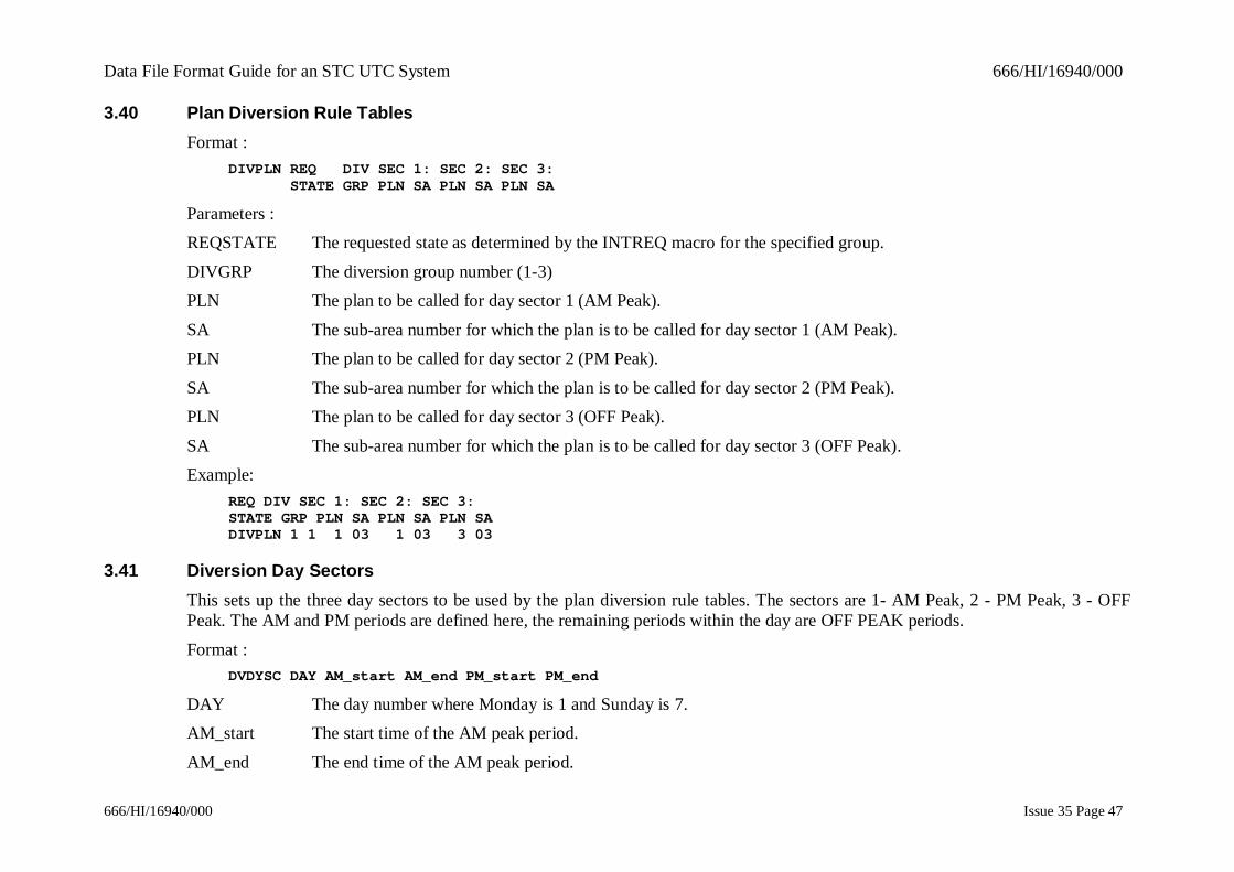
3.40 Plan Diversion Rule TablesFormat :
DIVPLN REQ DIV SEC 1: SEC 2: SEC 3: STATE GRP PLN SA PLN SA PLN SA
Parameters :REQSTATE The requested state as determined by the INTREQ macro for the specified group.
DIVGRP The diversion group number (1-3)PLN The plan to be called for day sector 1 (AM Peak).
SA The sub-area number for which the plan is to be called for day sector 1 (AM Peak).PLN The plan to be called for day sector 2 (PM Peak).
SA The sub-area number for which the plan is to be called for day sector 2 (PM Peak).PLN The plan to be called for day sector 3 (OFF Peak).
SA The sub-area number for which the plan is to be called for day sector 3 (OFF Peak).Example:
REQ DIV SEC 1: SEC 2: SEC 3:STATE GRP PLN SA PLN SA PLN SADIVPLN 1 1 1 03 1 03 3 03
3.41 Diversion Day SectorsThis sets up the three day sectors to be used by the plan diversion rule tables. The sectors are 1- AM Peak, 2 - PM Peak, 3 - OFFPeak. The AM and PM periods are defined here, the remaining periods within the day are OFF PEAK periods.
Format :DVDYSC DAY AM_start AM_end PM_start PM_end
DAY The day number where Monday is 1 and Sunday is 7.AM_start The start time of the AM peak period.
AM_end The end time of the AM peak period.

Data File Format Guide for an STC UTC System 666/HI/16940/000
666/HI/16940/000 Issue 35 Page 48
PM_start The start time of the PM peak period.
PM_end The end time of the PM peak period.Example:
DAY AM_start AM_end PM_start PM_endDVDYSC 1 0800 1000 1600 1730DVDYSC 2 0810 1010 1630 1800
3.42 Diversion Plan Delay Switching TimetablesThis is used to set the delay between the diversion request or cancellation, and the introduction of the new plan. The INTRO TIME isthe delay between entering the operator command to introduce the diversion and the new plan being introduced. The CANCEL TIMEis the delay between entering the operator command to cancel the diversion and the new plan being cancelled, depending on theSTATE from which the diversion group is coming.
Format:DVPDLY REQ DIV CANCEL INTRO STATE GRP TIME TIME
Parameters:REQSTATE The requested state as determined by the INTREQ macro.
DIVGRP The diversion group number (1-3).CANCEL TIME The time delay in 1/2 minutes before the plan is cancelled.
The plan is specified by the DIVPLN macro. The STATE used is the STATE that the group was in before thediversion is cancelled.
INTRO TIME The time delay in 1/2 minutes before the plan is introduced.Examples:
REQ DIV CANCEL INTRO STATE GRP TIME TIMEDVPDLY 1 1 10 20DVPDLY 2 1 10 15
Data File Format Guide for an STC UTC System 666/HI/16940/000
666/HI/16940/000 Issue 35 Page 49
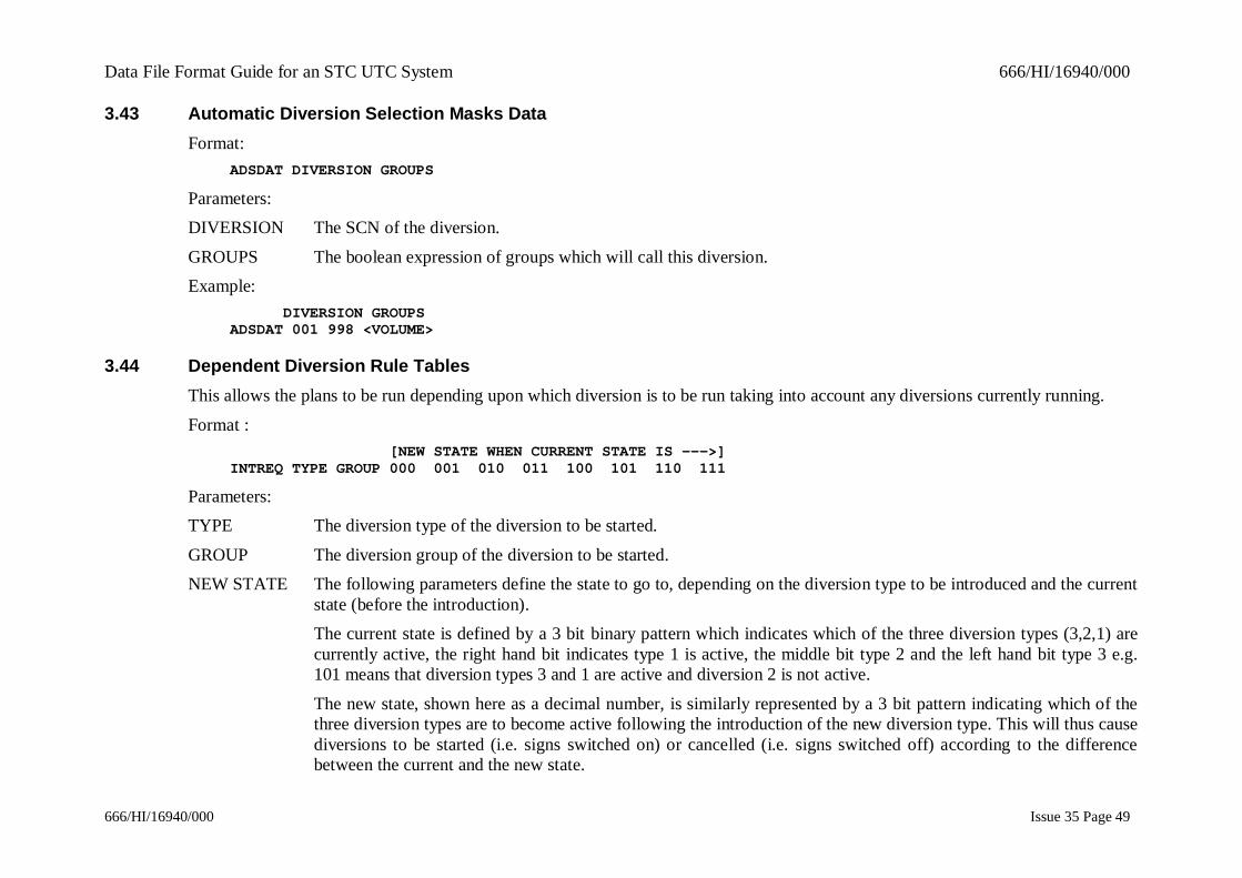
3.43 Automatic Diversion Selection Masks DataFormat:
ADSDAT DIVERSION GROUPS
Parameters:DIVERSION The SCN of the diversion.
GROUPS The boolean expression of groups which will call this diversion.Example:
DIVERSION GROUPSADSDAT 001 998 <VOLUME>
3.44 Dependent Diversion Rule TablesThis allows the plans to be run depending upon which diversion is to be run taking into account any diversions currently running.
Format : [NEW STATE WHEN CURRENT STATE IS --->]INTREQ TYPE GROUP 000 001 010 011 100 101 110 111
Parameters:TYPE The diversion type of the diversion to be started.
GROUP The diversion group of the diversion to be started.NEW STATE The following parameters define the state to go to, depending on the diversion type to be introduced and the current
state (before the introduction).The current state is defined by a 3 bit binary pattern which indicates which of the three diversion types (3,2,1) arecurrently active, the right hand bit indicates type 1 is active, the middle bit type 2 and the left hand bit type 3 e.g.101 means that diversion types 3 and 1 are active and diversion 2 is not active.
The new state, shown here as a decimal number, is similarly represented by a 3 bit pattern indicating which of thethree diversion types are to become active following the introduction of the new diversion type. This will thus causediversions to be started (i.e. signs switched on) or cancelled (i.e. signs switched off) according to the differencebetween the current and the new state.
Data File Format Guide for an STC UTC System 666/HI/16940/000
666/HI/16940/000 Issue 35 Page 50
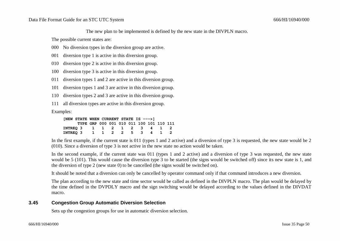
The new plan to be implemented is defined by the new state in the DIVPLN macro.
The possible current states are:000 No diversion types in the diversion group are active.
001 diversion type 1 is active in this diversion group.010 diversion type 2 is active in this diversion group.
100 diversion type 3 is active in this diversion group.011 diversion types 1 and 2 are active in this diversion group.
101 diversion types 1 and 3 are active in this diversion group.110 diversion types 2 and 3 are active in this diversion group.
111 all diversion types are active in this diversion group.Examples:
[NEW STATE WHEN CURRENT STATE IS --->] TYPE GRP 000 001 010 011 100 101 110 111INTREQ 3 1 1 2 1 2 3 4 1 2INTREQ 3 1 1 2 2 5 3 4 1 2
In the first example, if the current state is 011 (types 1 and 2 active) and a diversion of type 3 is requested, the new state would be 2(010). Since a diversion of type 3 is not active in the new state no action would be taken.
In the second example, if the current state was 011 (types 1 and 2 active) and a diversion of type 3 was requested, the new statewould be 5 (101). This would cause the diversion type 3 to be started (the signs would be switched off) since its new state is 1, andthe diversion of type 2 (new state 0) to be cancelled (the signs would be switched on).It should be noted that a diversion can only be cancelled by operator command only if that command introduces a new diversion.
The plan according to the new state and time sector would be called as defined in the DIVPLN macro. The plan would be delayed bythe time defined in the DVPDLY macro and the sign switching would be delayed according to the values defined in the DIVDATmacro.
3.45 Congestion Group Automatic Diversion SelectionSets up the congestion groups for use in automatic diversion selection.

Data File Format Guide for an STC UTC System 666/HI/16940/000
666/HI/16940/000 Issue 35 Page 51
Format:ADSCON DIVERSION TRIGGER DETECTORS
Parameters:
DIVERSION Sub-area number.TRIGGER Has values 0/1 where
0 = All detectors in a group have to be on before the group is on;1 = If one of the detectors in the group is on then the group is on.
DETECTORS The list of SCNs of the appropriate detector type.Example:
SUBAREA TRIGGER DETECTORSADSCON 093 115 1 001 999 000 000 000 000 000 000
3.46 Long Queue Groups Automatic Diversion SelectionSets up the long queue groups for use in automatic diversion selection.
Format:ADSLNQ DIVERSION TRIGGER DETECTORS
Parameters:DIVERSION Sub-area number.
TRIGGER Has values 0/1 where0 = All detectors in a group have to be on before the group is on;
1 = If one of the detectors in the group is on then the group is on.DETECTORS The list of SCNs of the appropriate detector type.
Example:DIVERSION TRIGGER DETECTORSADSLNQ 093 116 1 001 999 000 000 000 000 000 000
Data File Format Guide for an STC UTC System 666/HI/16940/000
666/HI/16940/000 Issue 35 Page 52
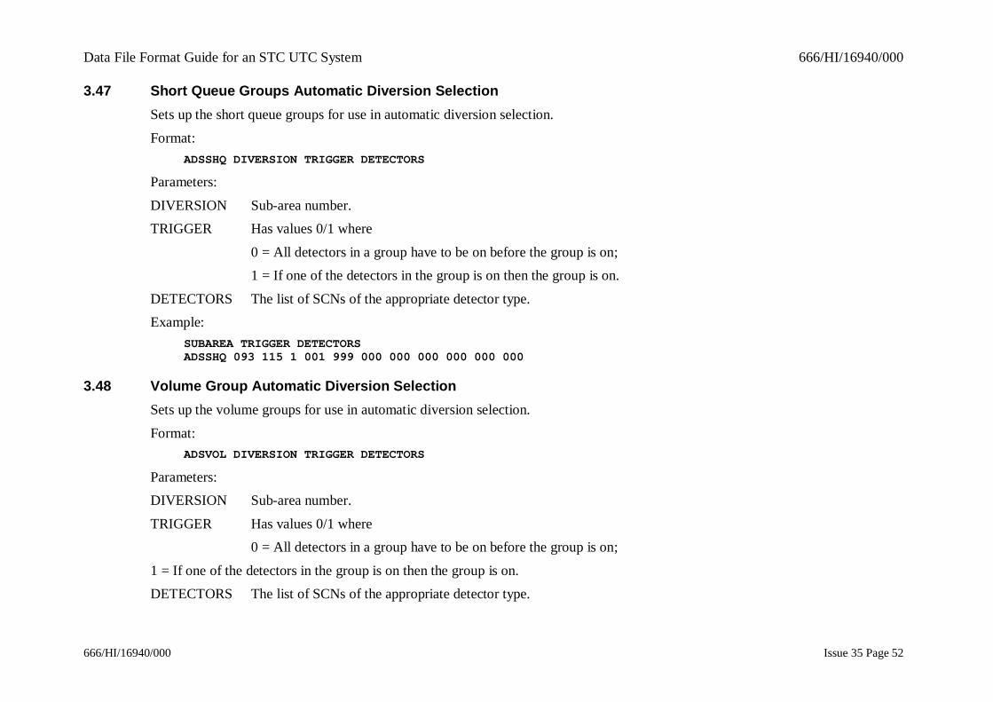
3.47 Short Queue Groups Automatic Diversion SelectionSets up the short queue groups for use in automatic diversion selection.
Format:ADSSHQ DIVERSION TRIGGER DETECTORS
Parameters:
DIVERSION Sub-area number.TRIGGER Has values 0/1 where
0 = All detectors in a group have to be on before the group is on;1 = If one of the detectors in the group is on then the group is on.
DETECTORS The list of SCNs of the appropriate detector type.Example:
SUBAREA TRIGGER DETECTORSADSSHQ 093 115 1 001 999 000 000 000 000 000 000
3.48 Volume Group Automatic Diversion SelectionSets up the volume groups for use in automatic diversion selection.
Format:ADSVOL DIVERSION TRIGGER DETECTORS
Parameters:DIVERSION Sub-area number.
TRIGGER Has values 0/1 where0 = All detectors in a group have to be on before the group is on;
1 = If one of the detectors in the group is on then the group is on.DETECTORS The list of SCNs of the appropriate detector type.
Data File Format Guide for an STC UTC System 666/HI/16940/000
666/HI/16940/000 Issue 35 Page 53
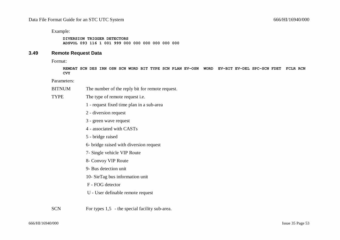
Example:DIVERSION TRIGGER DETECTORSADSVOL 093 116 1 001 999 000 000 000 000 000 000
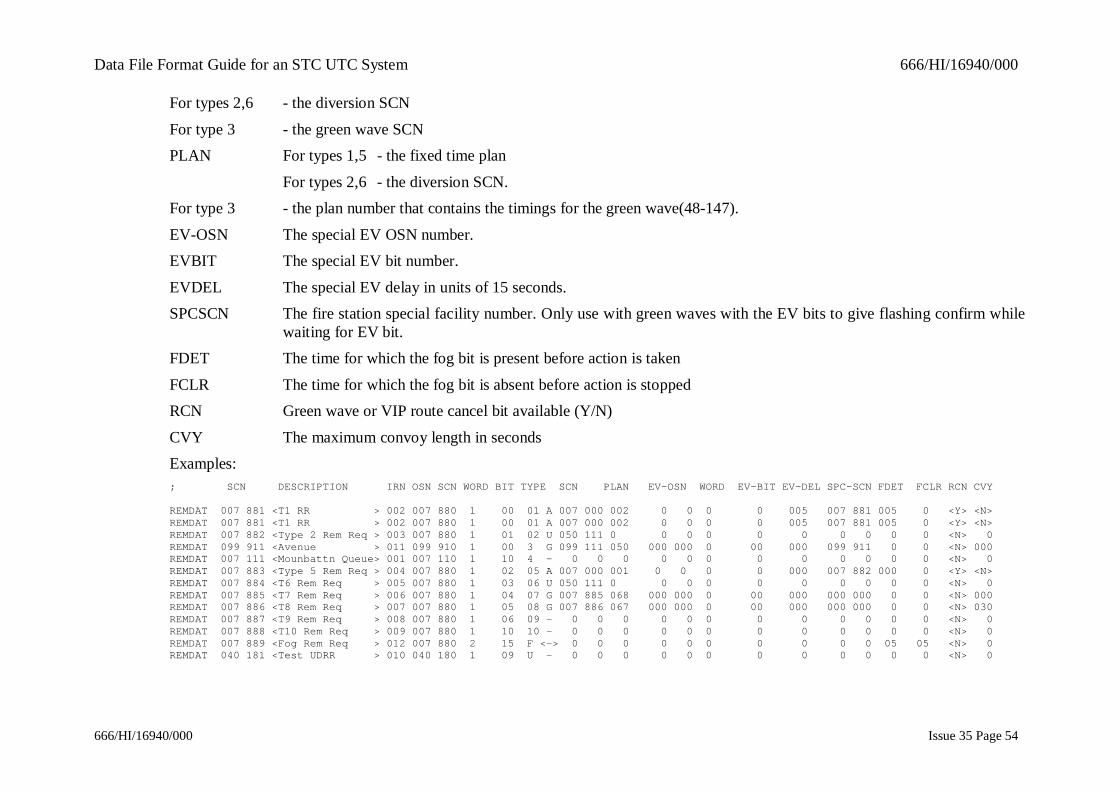
3.49 Remote Request DataFormat:
REMDAT SCN DES IRN OSN SCN WORD BIT TYPE SCN PLAN EV-OSN WORD EV-BIT EV-DEL SPC-SCN FDET FCLR RCNCVY
Parameters:BITNUM The number of the reply bit for remote request.
TYPE The type of remote request i.e.1 - request fixed time plan in a sub-area
2 - diversion request3 - green wave request
4 - associated with CASTs5 - bridge raised
6- bridge raised with diversion request7- Single vehicle VIP Route
8- Convoy VIP Route9- Bus detection unit
10- SieTag bus information unit F - FOG detector
U - User definable remote request
SCN For types 1,5 - the special facility sub-area.
Data File Format Guide for an STC UTC System 666/HI/16940/000
666/HI/16940/000 Issue 35 Page 54
For types 2,6 - the diversion SCN
For type 3 - the green wave SCNPLAN For types 1,5 - the fixed time plan
For types 2,6 - the diversion SCN.For type 3 - the plan number that contains the timings for the green wave(48-147).
EV-OSN The special EV OSN number.EVBIT The special EV bit number.
EVDEL The special EV delay in units of 15 seconds.SPCSCN The fire station special facility number. Only use with green waves with the EV bits to give flashing confirm while
waiting for EV bit.FDET The time for which the fog bit is present before action is taken
FCLR The time for which the fog bit is absent before action is stoppedRCN Green wave or VIP route cancel bit available (Y/N)
CVY The maximum convoy length in secondsExamples:; SCN DESCRIPTION IRN OSN SCN WORD BIT TYPE SCN PLAN EV-OSN WORD EV-BIT EV-DEL SPC-SCN FDET FCLR RCN CVY
REMDAT 007 881 <T1 RR > 002 007 880 1 00 01 A 007 000 002 0 0 0 0 005 007 881 005 0 <Y> <N>REMDAT 007 881 <T1 RR > 002 007 880 1 00 01 A 007 000 002 0 0 0 0 005 007 881 005 0 <Y> <N>REMDAT 007 882 <Type 2 Rem Req > 003 007 880 1 01 02 U 050 111 0 0 0 0 0 0 0 0 0 0 <N> 0REMDAT 099 911 <Avenue > 011 099 910 1 00 3 G 099 111 050 000 000 0 00 000 099 911 0 0 <N> 000REMDAT 007 111 <Mounbattn Queue> 001 007 110 1 10 4 - 0 0 0 0 0 0 0 0 0 0 0 0 <N> 0REMDAT 007 883 <Type 5 Rem Req > 004 007 880 1 02 05 A 007 000 001 0 0 0 0 000 007 882 000 0 <Y> <N>REMDAT 007 884 <T6 Rem Req > 005 007 880 1 03 06 U 050 111 0 0 0 0 0 0 0 0 0 0 <N> 0REMDAT 007 885 <T7 Rem Req > 006 007 880 1 04 07 G 007 885 068 000 000 0 00 000 000 000 0 0 <N> 000REMDAT 007 886 <T8 Rem Req > 007 007 880 1 05 08 G 007 886 067 000 000 0 00 000 000 000 0 0 <N> 030REMDAT 007 887 <T9 Rem Req > 008 007 880 1 06 09 - 0 0 0 0 0 0 0 0 0 0 0 0 <N> 0REMDAT 007 888 <T10 Rem Req > 009 007 880 1 10 10 - 0 0 0 0 0 0 0 0 0 0 0 0 <N> 0REMDAT 007 889 <Fog Rem Req > 012 007 880 2 15 F <-> 0 0 0 0 0 0 0 0 0 0 05 05 <N> 0REMDAT 040 181 <Test UDRR > 010 040 180 1 09 U - 0 0 0 0 0 0 0 0 0 0 0 0 <N> 0
Data File Format Guide for an STC UTC System 666/HI/16940/000
666/HI/16940/000 Issue 35 Page 55
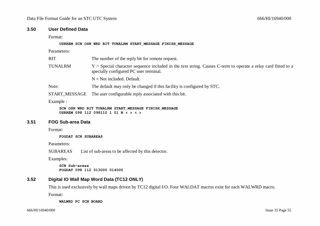
3.50 User Defined DataFormat:
USRREM SCN OSN WRD BIT TUNALRM START_MESSAGE FINISH_MESSAGE
Parameters:BIT The number of the reply bit for remote request.
TUNALRM Y = Special character sequence included in the text string. Causes C-term to operate a relay card fitted to aspecially configured PC user terminal.
N = Not included. Default.Note: The default may only be changed if this facility is configured by STC.
START_MESSAGE The user configurable reply associated with this bit.Example :
SCN OSN WRD BIT TUNALRM START_MESSAGE FINISH_MESSAGEUSRREM 098 112 098110 1 01 N < > < >
3.51 FOG Sub-area DataFormat:
FOGDAT SCN SUBAREAS
Parameters:
SUBAREAS List of sub-areas to be affected by this detector.Examples:
SCN Sub-areasFOGDAT 098 112 013000 014000
3.52 Digital IO Wall Map Word Data (TC12 ONLY)This is used exclusively by wall maps driven by TC12 digital I/O. Four WALDAT macros exist for each WALWRD macro.
Format:WALWRD PC SCN BOARD
Data File Format Guide for an STC UTC System 666/HI/16940/000
666/HI/16940/000 Issue 35 Page 56
Parameters:
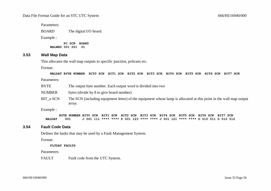
BOARD The digital I/O board.Example :
PC SCN BOARDWALWRD 001 001 01
3.53 Wall Map DataThis allocates the wall map outputs to specific junction, pelicans etc.
Format:WALDAT BYTE NUMBER BIT0 SCN BIT1 SCN BIT2 SCN BIT3 SCN BIT4 SCN BIT5 SCN BIT6 SCN BIT7 SCN
Parameters:BYTE The output byte number. Each output word is divided into two
NUMBER bytes (divide by 8 to give board number)BIT_n SCN The SCN (including equipment letter) of the equipment whose lamp is allocated at this point in the wall map output
array.Example :
BYTE NUMBER BIT0 SCN BIT1 SCN BIT2 SCN BIT3 SCN BIT4 SCN BIT5 SCN BIT6 SCN BIT7 SCNWALDAT 001 J 001 111 **** **** P 001 123 **** **** J 001 121 **** **** D 010 511 D 010 512
3.54 Fault Code DataDefines the faults that may be used by a Fault Management System.
Format:FLTDAT FAULTS
Parameters:
FAULT Fault code from the UTC System.
Data File Format Guide for an STC UTC System 666/HI/16940/000
666/HI/16940/000 Issue 35 Page 57
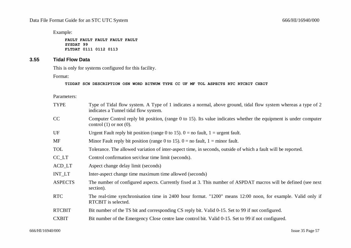
Example:FAULT FAULT FAULT FAULT FAULTSYSDAT 99FLTDAT 0111 0112 0113
3.55 Tidal Flow DataThis is only for systems configured for this facility.
Format:TIDDAT SCN DESCRIPTION OSN WORD BITNUM TYPE CC UF MF TOL ASPECTS RTC RTCBIT CXBIT
Parameters:
TYPE Type of Tidal flow system. A Type of 1 indicates a normal, above ground, tidal flow system whereas a type of 2indicates a Tunnel tidal flow system.
CC Computer Control reply bit position, (range 0 to 15). Its value indicates whether the equipment is under computercontrol (1) or not (0).
UF Urgent Fault reply bit position (range 0 to 15). 0 = no fault, 1 = urgent fault.MF Minor Fault reply bit position (range 0 to 15). 0 = no fault, 1 = minor fault.
TOL Tolerance. The allowed variation of inter-aspect time, in seconds, outside of which a fault will be reported.CC_LT Control confirmation set/clear time limit (seconds).
ACD_LT Aspect change delay limit (seconds)INT_LT Inter-aspect change time maximum time allowed (seconds)
ASPECTS The number of configured aspects. Currently fixed at 3. This number of ASPDAT macros will be defined (see nextsection).
RTC The real-time synchronisation time in 2400 hour format. "1200" means 12:00 noon, for example. Valid only ifRTCBIT is selected.
RTCBIT Bit number of the TS bit and corresponding CS reply bit. Valid 0-15. Set to 99 if not configured.CXBIT Bit number of the Emergency Close centre lane control bit. Valid 0-15. Set to 99 if not configured.
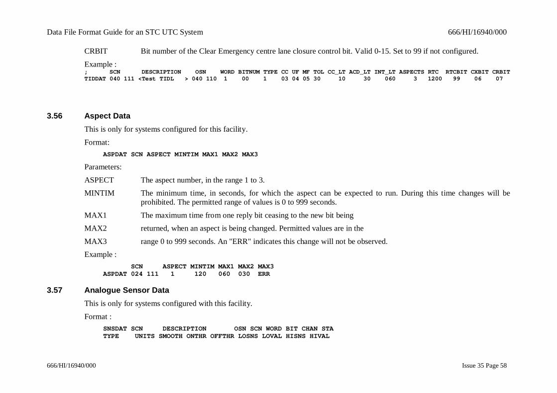
Data File Format Guide for an STC UTC System 666/HI/16940/000
666/HI/16940/000 Issue 35 Page 58
CRBIT Bit number of the Clear Emergency centre lane closure control bit. Valid 0-15. Set to 99 if not configured.
Example :; SCN DESCRIPTION OSN WORD BITNUM TYPE CC UF MF TOL CC_LT ACD_LT INT_LT ASPECTS RTC RTCBIT CXBIT CRBITTIDDAT 040 111 <Test TIDL > 040 110 1 00 1 03 04 05 30 10 30 060 3 1200 99 06 07
3.56 Aspect DataThis is only for systems configured for this facility.
Format:ASPDAT SCN ASPECT MINTIM MAX1 MAX2 MAX3
Parameters:
ASPECT The aspect number, in the range 1 to 3.MINTIM The minimum time, in seconds, for which the aspect can be expected to run. During this time changes will be
prohibited. The permitted range of values is 0 to 999 seconds.
MAX1 The maximum time from one reply bit ceasing to the new bit beingMAX2 returned, when an aspect is being changed. Permitted values are in the
MAX3 range 0 to 999 seconds. An "ERR" indicates this change will not be observed.Example :
SCN ASPECT MINTIM MAX1 MAX2 MAX3ASPDAT 024 111 1 120 060 030 ERR
3.57 Analogue Sensor DataThis is only for systems configured with this facility.
Format :SNSDAT SCN DESCRIPTION OSN SCN WORD BIT CHAN STATYPE UNITS SMOOTH ONTHR OFFTHR LOSNS LOVAL HISNS HIVAL

Data File Format Guide for an STC UTC System 666/HI/16940/000
666/HI/16940/000 Issue 35 Page 59
Parameters :
BIT Bit position on the OTU, either 0 or 8CHAN Sensor channel number in the range 1 to 15
STA Status Channel. 0 = NO, 1 = YES. Whether this channel contains status information for the sensor.TYPE A free format text string for defining the sensor channel type. It is suggested that a standard set of type descriptors
be defined for all sensors on a system.UNITS A free format text string for defining the units of measurement. It is suggested that a standard set of measurement
descriptors be defined for each system.ONTHR Alarm ON threshold. If the sensor value passes this threshold then an alarm is set.
OFFTHR Alarm OFF threshold. If the sensor value passes below this threshold then the alarm is cleared.LOSNS Low raw sensor data used to calibrate a real value (see LOVAL)
LOVAL The real sensor value when the sensor output is the same as that given by LOSNS.HISNS High raw sensor data used to calibrate a real value (see HIVAL)
HIVAL The real sensor value when the sensor output is the same as that given by HISNS.Example :
SNSDAT SCN DESCRIPTION OSN SCN WORD BIT CHAN STAT TYPE UNITS ONTHR OFFTHR LOSNS LOVAL HISNS HIVAL
SNSDAT 077 141 <test 1 > 077 140 1 0 01 0 <NO2 > <ppb > 50 40 0001 -555 1023 2000
3.58 Analogue Sensor Group DataThis is only for systems configured with this facility.
Format :BEGGRPGRPSNSENDLIS
Parameters :BEGGRP Beginning of the group definition.
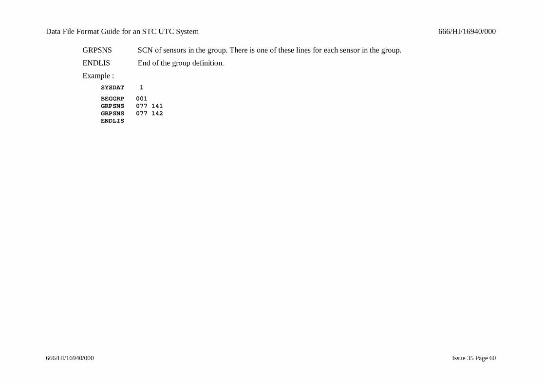
Data File Format Guide for an STC UTC System 666/HI/16940/000
666/HI/16940/000 Issue 35 Page 60
GRPSNS SCN of sensors in the group. There is one of these lines for each sensor in the group.
ENDLIS End of the group definition.Example :
SYSDAT 1
BEGGRP 001GRPSNS 077 141GRPSNS 077 142ENDLIS
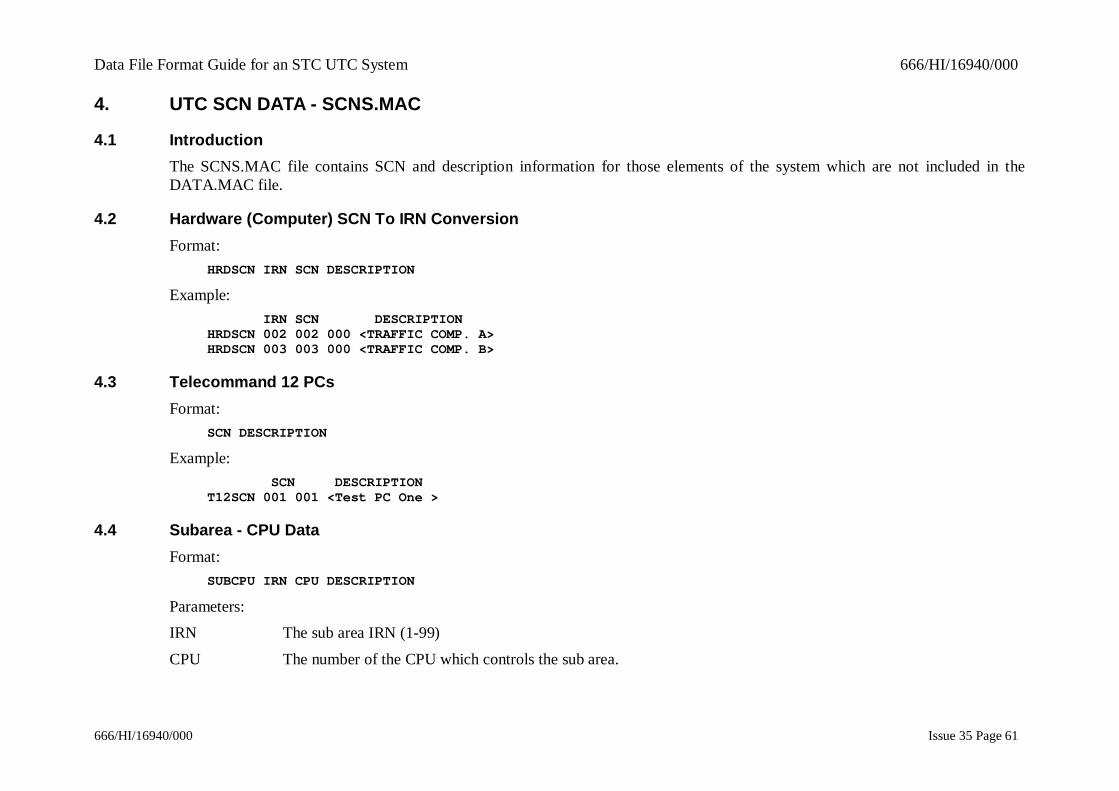
Data File Format Guide for an STC UTC System 666/HI/16940/000
666/HI/16940/000 Issue 35 Page 61
4. UTC SCN DATA - SCNS.MAC
4.1 IntroductionThe SCNS.MAC file contains SCN and description information for those elements of the system which are not included in theDATA.MAC file.
4.2 Hardware (Computer) SCN To IRN ConversionFormat:
HRDSCN IRN SCN DESCRIPTION
Example: IRN SCN DESCRIPTIONHRDSCN 002 002 000 <TRAFFIC COMP. A>HRDSCN 003 003 000 <TRAFFIC COMP. B>
4.3 Telecommand 12 PCsFormat:
SCN DESCRIPTION
Example: SCN DESCRIPTIONT12SCN 001 001 <Test PC One >
4.4 Subarea - CPU DataFormat:
SUBCPU IRN CPU DESCRIPTION
Parameters:IRN The sub area IRN (1-99)
CPU The number of the CPU which controls the sub area.
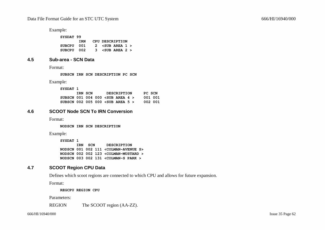
Data File Format Guide for an STC UTC System 666/HI/16940/000
666/HI/16940/000 Issue 35 Page 62
Example:SYSDAT 99 IRN CPU DESCRIPTIONSUBCPU 001 2 <SUB AREA 1 >SUBCPU 002 3 <SUB AREA 2 >
4.5 Sub-area - SCN DataFormat:
SUBSCN IRN SCN DESCRIPTION PC SCN
Example:SYSDAT 1 IRN SCN DESCRIPTION PC SCNSUBSCN 001 004 000 <SUB AREA 4 > 001 001SUBSCN 002 005 000 <SUB AREA 5 > 002 001
4.6 SCOOT Node SCN To IRN ConversionFormat:
NODSCN IRN SCN DESCRIPTION
Example:SYSDAT 1 IRN SCN DESCRIPTIONNODSCN 001 002 111 <COLMAN-AVENUE S>NODSCN 002 002 123 <COLMAN-MUSTARD >NODSCN 003 002 131 <COLMAN-S PARK >
4.7 SCOOT Region CPU DataDefines which scoot regions are connected to which CPU and allows for future expansion.
Format:REGCPU REGION CPU
Parameters:REGION The SCOOT region (AA-ZZ).

Data File Format Guide for an STC UTC System 666/HI/16940/000
666/HI/16940/000 Issue 35 Page 63
CPU The number of the CPU which controls the SCOOT region.
Example: REGION CPUREGCPU AP 1REGCPU AS 1
4.8 Green Wave SCN To IRN ConversionFormat:
GWVSCN SCN DESCRIPTION IRN
Examples: SCN DESCRIPTION IRNGWVSCN 011 111 <HIGH STREET > 001GWVSCN 011 112 <BRIDGE STREET > 002
4.9 OMU DataFormat:
OMUSCN SCN DESCRIPTION
Examples:OMUSCN 040 111 <Badgers Barn >
4.10 NMCS DataThis macro cross references UTC SCNs to NMCS geographical references for equipments controlled by UTC via an NMCS system.
Format:NMCDAT SCN TCC EQUIP IDENTITY
Examples: SCN TCC EQUIP IDENTITYNMCDAT K 042 115 1 <TLI> <A4232/9220A1 >
Data File Format Guide for an STC UTC System 666/HI/16940/000
666/HI/16940/000 Issue 35 Page 64
5. JUNCTION TIMINGS DATA - TIMINGS.DAT
5.1 Timing TolerancesFormat:
TIMTOL MINSTG MAXSTG INTGREEN MAXCCTIME CONTOL CONCLR 1HRTOL 1HRCLR 3MINTOL 3MINCLR
Parameters:MINSTG The tolerance to be applied to measurements of the minimum stage green times, (1-9 sec)
MAXSTG The tolerance to be applied to measurements of the maximum stage green times, (1-9 sec)INTGREEN The tolerance to be applied to measurements of the inter green times, (1-9 sec).
MAXCCTIME The maximum time to be used for controller checks, (1-19 minutes).CONTOL Tolerance Time for all three faults.
CONCLR Clear Time for all three faults.1HRTOL Number of faults tolerated in 1Hr.
1HRCLR Clear tolerance for number of faults tolerated in 1Hr.3MINTOL Number of faults tolerated in a 3 minute period.
3MINCLR Clear tolerance for faults tolerated in 3 minute period.Example:
MINSTG MAXSTG INTGREEN MAXCCTIME CONTOL CONCLR 1HRTOL 1HRCLR 3MINTOL 3MINCLRTIMTOL 2 5 4 10 3 30 15 15 15 180
5.2 General System-wide TimingsFormat:
GENTIM CPS RESP DVS RESP SD STUCK
Parameters:
CPS RESP Maximum response time for car park signs.DVS RESP Maximum response time for diversion signs.
Data File Format Guide for an STC UTC System 666/HI/16940/000
666/HI/16940/000 Issue 35 Page 65
SD STUCK SD Bit stuck timeout limit.
Example: CPS RESP DVS RESP SD STUCKGENTIM 60 040 24
5.3 Controller Timings - IntersectionsFormat:
ISN SCN NUM STAGES
This macro defines to which intersection the following data applies.Example:
ISN 01121 2
5.4 Controller Timings - Stage TimingsThis macro defines the minimum and maximum green for the stage, whether it is valid to move to this stage from another stage and ifso the intergreen time. There must be one DEFSTG for each possible stage, the first DEFSTG is stage A, the second stage B etc.
Format:DEFSTG TYPE MAX MIN STG1 STG2 STG3 STG.....
Parameters:
TYPE The stage type, NORM for a normal stage, DD for dependent stages.MAX The maximum green in seconds for this stage in fallback mode. Range 0- 127. This value MUST be the 'stage run
time' defined in the controller for the time of day that the timetable initiated controller checks program is to run. Ifcontroller checks are run by operator command, the value defined here may not be the same as that defined for thecontroller at the time that the controller checks program is run. In this case 'maximum green fault' error messageswill be output by controller checks.
MIN The minimum green for the stage in seconds. Range 0-68. Min must be smaller than max.STG'n' This field specifies whether you can move from the current stage to stage 'n'. If the move is possible then the
intergreen value in seconds is inserted, if not then NOS(no such stage change) is used. At the junction from onestage to itself a NOS should be entered as an 'x' in the data entry screen. The stages should be read as 1, 2, 3, etc
Data File Format Guide for an STC UTC System 666/HI/16940/000
666/HI/16940/000 Issue 35 Page 66
across the columns from left to right and from top to bottom in the rows. The intergreen time shown is that from thestage represented by the row to the stage represented by the column. The number of columns and rows will be thesame as that specified for the number of stages in the Junction data form, or ISNDAT macro.
Example: Type Max Min Stg1 Stg2 Stg3 Stg4 ...DEFSTG NORM 20 7 NOS 6 7 7DEFSTG NORM 40 7 5 NOS 5 NOSDEFSTG D1 16 7 5 NOS NOS 7DEFSTG D2 7 7 NOS 7 7 NOS
5.5 Controller timings - Upper Stage TimingsIf the controller has been configured for upper and lower stage timings, this macro defines the upper values for each equivalent lower(default) value defined in section 5.4. Each upper timing must be equal or greater to the equivalent lower value, and defined and non-existent intergreens must correspond exactly to the defaults. There must be one UPRSTG for each possible stage, the first UPRSTGis stage A, the second stage B etc.
Format:UPRSTG TYPE MAX MIN STG1 STG2 STG3 STG.....
Parameters:TYPE This parameter is left blank for the upper timings. See 5.4 for the stage types.
MAX See 5.4.MIN See 5.4.
STG'n' See 5.4.Example:
From From From From From ...Type Max Min Stg1 Stg2 Stg3 Stg4 Stg5 ...UPRSTG 25 10 NOS 7 7 7UPRSTG 40 10 8 NOS 7 NOSUPRSTG 20 10 10 NOS NOS 7UPRSTG 15 10 NOS 7 7 N0S

Data File Format Guide for an STC UTC System 666/HI/16940/000
666/HI/16940/000 Issue 35 Page 67
5.6 Controller Timings - Fallback And TestThis macro defines the maximum green fallback cycle test sequence.
Format:FBACK P1 P2 P3 P4 P5
Parameters:
P1 The cycle time in fallback mode or NSNT for "No synchronisation and no controller checks" NSBT for "Nosynchronisation but controller checks of (VA, FT, ML)"
P2 The time in seconds into the group timer's cycle when this controllers fallback plan is to begin.P3 TESTFLAG this is either:
NOTEST for "fallback mode not to be tested".TALL for "fallback mode is always to be tested (VA, FT)".
TTDAY for "fallback mode only to be tested at time of day (timetable) checks (CLU, ML)".P4 The real-time synchronisation time in 2400 hour format. "1200" means 12:00 noon, for example.
P5 The next parameters specify the fallback sequence with all demands present. It MUST be the fallback sequencedefined in the controller for the time of day that the controller checks timetable initiated program is to run.
NOTE: If controller checks are run by operator command the fallback sequence may not be the same as that defined here(depending on when the checks are initiated). In this case an error will be reported by the controller checksprogram.
Example:FBACK NSBT 0 TALL 1200 1 2 3 4
5.7 Controller Timings - Cyclic Test SequenceThis allows the intergreens to be tested on a cyclic sequence. This macro is mandatory.
Format:MINGRN P1 P2...........P'n'
Data File Format Guide for an STC UTC System 666/HI/16940/000
666/HI/16940/000 Issue 35 Page 68
Parameters:
P1 Stage 1 on the test.P2... Stage 2
P'n' The last stage on the MINGRN line will be followed by the first stage on the NCIG line.NOTE: 'n' may be up to 3 times the number of configured controller stages.
Example:MINGRN 1 4 2 4 3 1 3 2
5.8 Controller Timings - Non-Cyclic Test SequenceThis allows the intergreens to be tested on a non-cyclic sequence. This macro is not mandatory.
Format:NCIG P1 P2...........P'n'
Parameters:
P1 Stage 1 on the test, this will be preceded by the last stage on the FBACK line.P2... Stage 2.
P'n' The last stage on the NCIG line will be followed by the first stage on the FBACK line.NOTE: 'n' may be up to 3 times the number of configured controller stages.
Example:NCIG 1 4 2 4 3 1 3 2
5.9 Controller Timings - Secondary Green TestsThis defines the stages (up to two) to be used for secondary maximum green tests.
Format:SECSTG P1 P2

Data File Format Guide for an STC UTC System 666/HI/16940/000
666/HI/16940/000 Issue 35 Page 69
Parameters:
P1/P2 The stages to be used for secondary maximum green tests.Example:
SECSTG 2 3

Data File Format Guide for an STC UTC System 666/HI/16940/000
666/HI/16940/000 Issue 35 Page 70
6. SCOOT DATAThe SCOOT data is held in a number of files. There is a header file (AREA.DAT) which contains a list of the data items which aregeneral to, and required by, the whole of the area under the control of SCOOT.All of the remaining data is held in 'region' files where a region is a geographical sub-division of the SCOOT area. The region filesare named as REGION.'nn' (where 'nn' is in the range AA to ZZ).The SYSDAT macro is used within each file to define for which computer the subsequent data is destined. In a single computersystem the SYSDAT macro is always equal to 1.The data is arranged hierarchically in each region file. The region specific data appears first, followed by one or more nodes. For eachnode there are numerous data items, some define the node itself, others define detectors, links, stages and UTC equipments whichbelong to the node.
For detailed explanations of the meaning of parameters defined in this document you should consult the SCOOT Traffic Handbook(Reference 1.3.10).
6.1 Area DataThere is only one AREDAT macro in the system. This macro is contained in a separate file called AREA.DAT. Before the data is'prepared' i.e. converted from the format shown here to that used by the on-line traffic system, and checked for validity, theAREA.DAT file is automatically concatenated with all the region files.
Format:AREDAT START LAG END LAG SET GATE MODEL LIGHT MEDIUM HEAVY NONE CONG FLT GRN FLT
Parameters:START LAG The normal system-wide start up delay for traffic on a link, i.e. the time lag before the traffic moves when the
signals go green.END LAG The normal system-wide end delay for traffic on a link, i.e. the time lag during which traffic continues to move after
the signals have changed from green.SET GATE For use with gating. This parameter should be set to 0 forMODEL setting gating from the SPLIT optimiser, and it should be set to 1 for setting gating from the SCOOT model.LIGHT Congestion Level - Range 1 to 98.
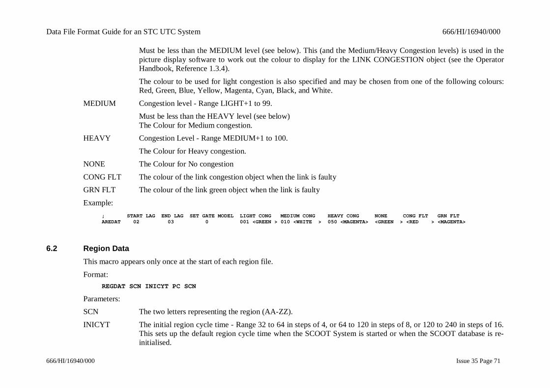
Data File Format Guide for an STC UTC System 666/HI/16940/000
666/HI/16940/000 Issue 35 Page 71
Must be less than the MEDIUM level (see below). This (and the Medium/Heavy Congestion levels) is used in thepicture display software to work out the colour to display for the LINK CONGESTION object (see the OperatorHandbook, Reference 1.3.4).
The colour to be used for light congestion is also specified and may be chosen from one of the following colours:Red, Green, Blue, Yellow, Magenta, Cyan, Black, and White.
MEDIUM Congestion level - Range LIGHT+1 to 99.Must be less than the HEAVY level (see below)The Colour for Medium congestion.
HEAVY Congestion Level - Range MEDIUM+1 to 100.
The Colour for Heavy congestion.NONE The Colour for No congestion
CONG FLT The colour of the link congestion object when the link is faultyGRN FLT The colour of the link green object when the link is faulty
Example:; START LAG END LAG SET GATE MODEL LIGHT CONG MEDIUM CONG HEAVY CONG NONE CONG FLT GRN FLTAREDAT 02 03 0 001 <GREEN > 010 <WHITE > 050 <MAGENTA> <GREEN > <RED > <MAGENTA>
6.2 Region DataThis macro appears only once at the start of each region file.
Format:REGDAT SCN INICYT PC SCN
Parameters:SCN The two letters representing the region (AA-ZZ).
INICYT The initial region cycle time - Range 32 to 64 in steps of 4, or 64 to 120 in steps of 8, or 120 to 240 in steps of 16.This sets up the default region cycle time when the SCOOT System is started or when the SCOOT database is re-initialised.

Data File Format Guide for an STC UTC System 666/HI/16940/000
666/HI/16940/000 Issue 35 Page 72
PC SCN SCN of the TC12 PC. The SCN consists of all zeros for TC8 Systems.
Example: SCN INICYT PC SCNREGDAT AP 120 010 001
6.3 Node DataA number of NODDAT macros will normally occur within a region file. As all the SCOOT data is listed hierarchically all the datawhich is subordinate to the node, i.e. equipment data (EQPDAT), stage data (STGDAT), link data (LNKDAT and LNKSTG), anddetector data (DETDAT and SOFDET), will be listed after a NODDAT macro together with any bus detector data. Once all the datawhich is subordinate to a particular node has been listed the next NODDAT macro (for the next node in the region) will occur.Format:
NODDAT SCN MAXCYT CYCFIX NAMSTG DOUBLE FORCED FIRST REMOVED IN SECOND REMOVED IN ;REMSTG 1 2 3 4 5 6 REMSTG 1 2 3 4 5 6
Parameters:
SCN The node SCN, subarea (2 digits with a leading zero) and node id (3 digits). By convention this is the same as theprincipal UTC equipment controlled by the node.
MAXCYT The maximum cycle time in seconds. Range 32 to 240.CYCFIX The cyclic fixed time. Range 0 to 63.
This is the amount of time during a SCOOT cycle that is lost to traffic (e.g. Pedestrian stages, intergreens ).NAMSTG The stage (usually with the longest duration) during which offset optimisation will occur.
REMSTG The removable stage on this node, i.e. a stage which may not be used at some times of day. Range - a STGDATSCN digit for this node (see Section 6.5), or 0 if there is no removable stage. There may only be one removablestage on a node.
DOUBLE Defines whether or not the node is initially double cycling. Must be set to Y or N.
FORCED Defines whether or not the cycling status of the node is to be forced. Must be set to Y or N.FIRSTREMSTGREMOVED
Defines whether or not the first removable stage is removed in eachof the translation plans 1 through 6. A 'Y' against a translation plannumber indicates the stage is removed, a 'N ' indicates the stage is
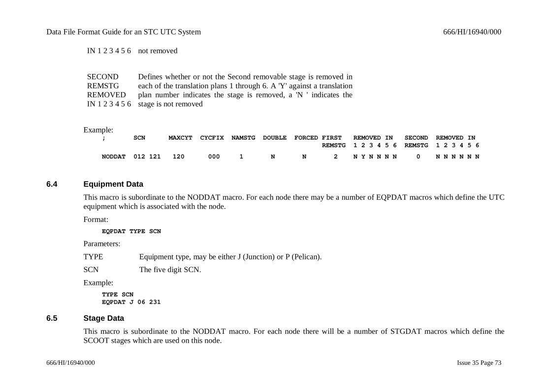
Data File Format Guide for an STC UTC System 666/HI/16940/000
666/HI/16940/000 Issue 35 Page 73
IN 1 2 3 4 5 6 not removed
SECONDREMSTGREMOVEDIN 1 2 3 4 5 6
Defines whether or not the Second removable stage is removed ineach of the translation plans 1 through 6. A 'Y' against a translationplan number indicates the stage is removed, a 'N ' indicates thestage is not removed
Example:; SCN MAXCYT CYCFIX NAMSTG DOUBLE FORCED FIRST REMOVED IN SECOND REMOVED IN REMSTG 1 2 3 4 5 6 REMSTG 1 2 3 4 5 6
NODDAT 012 121 120 000 1 N N 2 N Y N N N N 0 N N N N N N
6.4 Equipment DataThis macro is subordinate to the NODDAT macro. For each node there may be a number of EQPDAT macros which define the UTCequipment which is associated with the node.
Format:EQPDAT TYPE SCN
Parameters:
TYPE Equipment type, may be either J (Junction) or P (Pelican).SCN The five digit SCN.
Example:TYPE SCNEQPDAT J 06 231
6.5 Stage DataThis macro is subordinate to the NODDAT macro. For each node there will be a number of STGDAT macros which define theSCOOT stages which are used on this node.

Data File Format Guide for an STC UTC System 666/HI/16940/000
666/HI/16940/000 Issue 35 Page 74
Format:STGDAT SCN MOVEMENT MINLEN MAXLEN CHATIM
Parameters:
SCN The stage suffix, this is a digit ranging from 1 to 7, representing the stage part of the SCOOT SCN.MOVEMENT This parameter is used on SCOOT only systems to indicate which movement is to be forced on street..
MINLEN The minimum stage length. Range 7 to 63. This must include the longest preceding UTC intergreen.MAXLEN The maximum stage length. Range MINLEN to maximum SCOOT cycle time. The maximum must be greater than
or equal to the minimum.CHATIM This is the stage change time i.e. the time at which this stage starts in the cycle. Range 0 to node cycle time minus
1.Example:
SCN MOVEMENT MINLEN MAXLEN CHATIMSTGDAT 1 0 13 070 010STGDAT 2 0 23 080 056STGDAT 3 0 13 090 094
Note: The sum of the Minimum Stage lengths (MINLEN) must not be greater than the maximum SCOOT cycle time. The sum ofthe Maximum Stage lengths (MAXLEN) must be equal to or greater the maximum SCOOT cycle time.
6.6 Stage Skipping DataThis macro is subordinate to the NODDAT macro. For each node there will be a number of SSKDAT macros which define theSCOOT stages which may be skipped in a particular translation plan.
Format:SSKDAT SCN TRNPLN 1 2 3 4 5 6 7
Parameters:SCN The stage suffix, this is a digit ranging from 1 to 7, representing the stage part of the SCOOT SCN.
TRNPLN The number of the translation plan in which the specified stage may be skipped1, 2, 3, 4, 5, 6, 7 The stage number of the skip destination. If this stage is allowed as a destination stage this is denoted by Y

Data File Format Guide for an STC UTC System 666/HI/16940/000
666/HI/16940/000 Issue 35 Page 75
Example:; SCN TRNPLN 1 2 3 4 5 6 7
SSKDAT 2 1 N Y Y Y N
SSKDAT 3 1 Y Y N Y Y
6.7 Link DataThis macro is subordinate to the NODDAT macro. For each node there will be a number of LNKDAT macros which define theSCOOT links which are attached to the node. The hierarchical nature of the SCOOT data means that all the data which is subordinateto the link, i.e. the link stage data (LNKSTG), and detector data (DETDAT) and (SOFDET), will be listed after a LNKDAT macro.Once all the data which is subordinate to a particular link has been listed the next LNKDAT macro (for the next link on the currentnode) will occur.Format:
LNKDAT SCN TYPE SL? SLLINK C UNODE D U MAIND BOTNOD BLNK CONNOD CLNK SOFT? EQTYP EQPSCN STAGE GREENS A B C D E F G H
Parameters:SCN The link suffix, this is a letter representing the link part of the SCOOT SCN.
TYPE The link type, valid types are:N - a normal link (i.e. has different upstream and downstream nodes).
E - an entry link.X - an exit link.
F - a filter link.U - an uncontrolled link.
SL? This will be set to ‘Y’ if the link has a stop line detectorSLLINK The SCN of the stop line upstream link.
C The class of the link, either vehicular or bicycle. 'N' for normal (vehicle) link, 'B' for bicycle link.UNODE For normal links, the SCN of the upstream node. For other links, the current node number.
D The downstream node through stage. This is the stage SCN suffix of the current node which gives green to this link.

Data File Format Guide for an STC UTC System 666/HI/16940/000
666/HI/16940/000 Issue 35 Page 76
U The upstream node through stage. This is the stage SCN suffix at the upstream node which lets traffic onto this link.
MAIND The main downstream link suffix. This is the link downstream of the node which if blocked would cause outflowfrom the current link to cease. Valid entries are:
the link letter of a valid downstream link"0" if there is no main downstream link
BOTNOD The node for the bottleneck link, or all '0's if there is no bottleneck link.BLNK The link which if congested will cause the green time on the current link to be reduced, or '0' if there is no
bottleneck link.CONNOD The node associated with CONLNK.
CLNK The link whose weighting and importance factors will be used as an alternative when there is congestion on thecurrent link, or '0' if there is no congestion link.
SOFT? Set to 'Y' if this link is to be used for on-line saturation flow (SOFT) calculations, 'N' if not.EQTYP The type of UTC equipment which is associated with the control of traffic on this link either 'J' for a junction or 'P'
for a pelican.EQPSCN The SCN of the above junction or pelican. This must be one of the equipments defined in an EQPDAT macro for
the current node.STAGEGREENSA B C D E FG H
These eight fields define the UTC stages which will give green tothe current link. A '1' against a stage letter indicates that this UTCstage will give green to the link A '0' indicates either the stage doesnot give green to this link, or there is no such stage (intersectionswith more than 4 stages are uncommon).
Example: SCN TYPE SL? SLLINK C UNODE D U BD MAIND BOTNOD BLNK CONNOD CLNK SOFT? EQTYP EQPSCN STAGE GREENS A B C D E F G HLNKDAT L E N 000 000 N 001 222 2 0 0 C 000000 0 000 000 0 N J 001 123 0 1 0 0 0 0 0 0

Data File Format Guide for an STC UTC System 666/HI/16940/000
666/HI/16940/000 Issue 35 Page 77
6.8 SOFT detector dataThis macro is subordinate to the LNKDAT macro, it will only appear if the SOFT? parameter in the LNKDAT macro is set to 'Y'. Itis used to define SCOOT detectors
which may be used in the calculation of on-line saturation flow (SOFT).Format:
SOFDET DNODE LINK DETECTOR
Parameters:
DNODE The SCN of the down steam node to which the detector to be used for SOFT is connected.LINK The link on which the detector to be used for SOFT resides.
DETECTOR The number of the detector on the above link which is to be used for SOFT.Example:
DNODE LINK DETECTORSOFDET 001 211 E 1
6.9 Bus detector dataThis macro is subordinate to the LNKDAT macro, it will only appear if bus data is defined in the link data form.
Format:BUSDAT LINK TYPE BUSSCN BUSDET BUSTAG SCN READER ID
Parameters:LINK The link on which the bus detector resides.
TYPE The type of equipment which generates the bus demand which can be one of the following,J Junction controller
P Pelican ControllerZ Remote Request (type 9)
BUSSCN The SCN of the equipment which generates the bus demand.

Data File Format Guide for an STC UTC System 666/HI/16940/000
666/HI/16940/000 Issue 35 Page 78
BUSDET When the equipment is a junction or pelican controller, this is the number of the BD bit associated with this link.
BUSTAG SCN The SCN of the bus tag reader which is associated with this link which generates a type 10 remote requestREADER ID This is the identity of the bus reader.
Example: LINK TYPE BUSSCN BUSDET BUSTAG SCN READER IDBUSDAT G J 007 211 01 000 000 00
6.10 Link Stage dataThe LNKSTG macro is subordinate to the LNKDAT macro. Each LNKSTG macro is used to define 1 of up to 6 translation plans forthe link. Each translation plan defines whether the link is given green once or twice in the cycle and on which SCOOT stages thesegreens occur.
Format:LNKSTG TRNPLN GREENS 1stSTA 1stEND 2ndSTA 2ndEND
Parameters:
TRNPLN Up to 6 translation plans may be defined with associated link stage data. Plan 1 is compulsory.GREENS The number of times green is given to the link and vehicles exit from it. Range 1 to 2.
1stSTA The SCOOT stage on which the green for this link begins.1stEND The SCOOT stage on which the green for this link ends.
2ndSTA If there are two greens (GREENS = 2) this parameter defines the SCOOT stage on which the second green for thislink begins.
2ndEND If there are two greens (GREENS = 2) this parameter defines the SCOOT stage on which the second green for thislink ends.
Example: TRNPLN GREENS 1stSTA 1stEND 2ndSTA 2ndENDLNKSTG 1 2 1 3 5 6
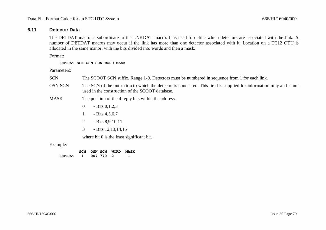
Data File Format Guide for an STC UTC System 666/HI/16940/000
666/HI/16940/000 Issue 35 Page 79
6.11 Detector DataThe DETDAT macro is subordinate to the LNKDAT macro. It is used to define which detectors are associated with the link. Anumber of DETDAT macros may occur if the link has more than one detector associated with it. Location on a TC12 OTU isallocated in the same manor, with the bits divided into words and then a mask.Format:
DETDAT SCN OSN SCN WORD MASK
Parameters:
SCN The SCOOT SCN suffix. Range 1-9. Detectors must be numbered in sequence from 1 for each link.OSN SCN The SCN of the outstation to which the detector is connected. This field is supplied for information only and is not
used in the construction of the SCOOT database.MASK The position of the 4 reply bits within the address.
0 - Bits 0,1,2,31 - Bits 4,5,6,7
2 - Bits 8,9,10,113 - Bits 12,13,14,15
where bit 0 is the least significant bit.Example:
SCN OSN SCN WORD MASKDETDAT 1 007 770 2 1

Data File Format Guide for an STC UTC System 666/HI/16940/000
666/HI/16940/000 Issue 35 Page 80
7. TIMETABLES
7.1 Dwyttb Timetables
7.1.1 Introduction
This file defines which timetable is to be used for each day of the year. There are two sets of definitions viz:
Date of year schedule.Day of week schedule.
Note: A useful feature when defining timetables is the ability to enter comments into the file, by preceding those comments with ;(semi-colon).
7.1.2 The Day of Year Schedule
Defines which timetable is to be used on a particular day of the year. A value here takes priority over a value in the day of weekschedule. If there is no definition in here for a particular date, the day of week schedule value is used.Format:
DATE TTABLE NO
Parameters:
DATE The date of year in the form dd:mmTTABLE NO The timetable number to be used for this date. This has a value between 1 and the max timetable number for this
system, standard system size 20.Examples:
10:03 0530:11 18
7.1.3 The Day of Week Schedule
Defines which timetable is to be used on a particular day of the week. If there is a value in the date of year schedule for the currentday of week, then that value is used instead of the value here.

Data File Format Guide for an STC UTC System 666/HI/16940/000
666/HI/16940/000 Issue 35 Page 81
Format:DAY TTABLE NO
Parameters:
DAY The day of the week.TTABLE NO The timetable number to be used for this date. This has a value between 1 and the max timetable number for this
system.Examples:
MONDAY 8THURSDAY 20
7.2 TOD'n'.MAC Timetables
7.2.1 IntroductionA Time of Day timetable file defines which events are to occur at a particular time, during the day for which the timetable has beenselected. There are 'n' possible timetables, where 'n' is a number in the range of 1 to 20. Each timetable is held in a separateTOD'n'.MAC file.Note: A useful feature when defining timetables is the ability to enter comments into the file, by preceding those comments with ;(semi-colon).Format:
<DESCRIPTN>TIME COMMAND <SCN><ScSCN><TERM><VALUE><STAGE><PARAM>
Parameters:
<DESCRIPTN> A description of the timetable can be included between the "<" and ">" brackets at the beginning of the timetablefile. The description has a maximum length of 40 characters and is displayed to a UTC System user by means of theOUTT command.
TIME The time of day at which the following command is to be actioned. It has the format:
HH:MM[:SS]where :
Data File Format Guide for an STC UTC System 666/HI/16940/000
666/HI/16940/000 Issue 35 Page 82
HH - hours (00 to 23)
MM - minutes (00 to 59)[SS] - seconds (00 to 59).
NOTES:(a) The seconds element of time is an optional parameter.
(b) If the time is preceded by a day of the week, e.g. Weds, then that command will only be actioned at that timeon the particular day of the week
(c) If the time is preceded by a date, e.g. 3-Apr-01, then that command will only be actioned at that time on theparticular date.
COMMAND The command to be actioned.The following parameters are command dependant, i.e. different commands require different parameters. Some parameters areoptional for a particular command. The exact format for a particular command may be found in the UTC System OperatorsHandbook ref. 1.3.4.
SCN The UTC System code number.ScSCN The SCOOT System code number.
These have the format LNNNNNwhere L - equipment letter.
NNNNN - five digit SCN number.TERM The terminal number.
VALUE A number.STAGE The stage identifier.
PARAM The SCOOT database parameter.NAME A particular name relevant to the command.
DATE The date of year.+/- Used when values are to be amended either positively or negatively.
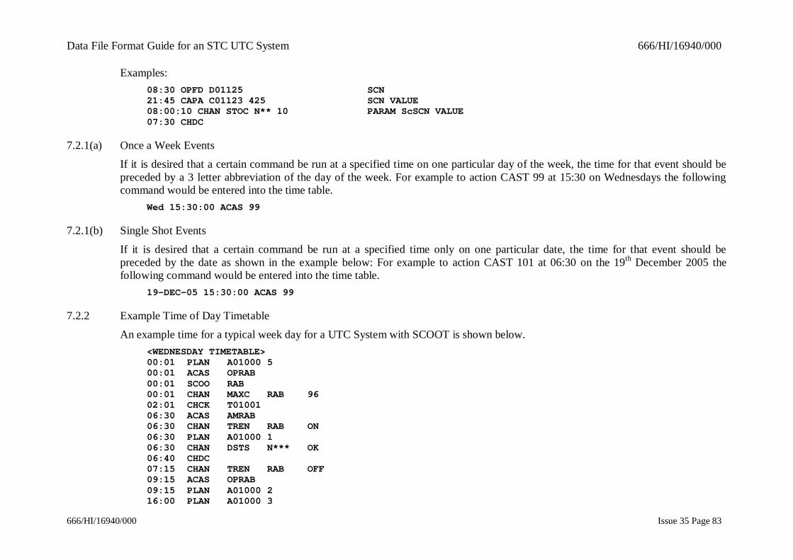
Data File Format Guide for an STC UTC System 666/HI/16940/000
666/HI/16940/000 Issue 35 Page 83
Examples:08:30 OPFD D01125 SCN21:45 CAPA C01123 425 SCN VALUE08:00:10 CHAN STOC N** 10 PARAM ScSCN VALUE07:30 CHDC
7.2.1(a) Once a Week Events
If it is desired that a certain command be run at a specified time on one particular day of the week, the time for that event should bepreceded by a 3 letter abbreviation of the day of the week. For example to action CAST 99 at 15:30 on Wednesdays the followingcommand would be entered into the time table.
Wed 15:30:00 ACAS 99
7.2.1(b) Single Shot Events
If it is desired that a certain command be run at a specified time only on one particular date, the time for that event should bepreceded by the date as shown in the example below: For example to action CAST 101 at 06:30 on the 19th December 2005 thefollowing command would be entered into the time table.
19-DEC-05 15:30:00 ACAS 99
7.2.2 Example Time of Day Timetable
An example time for a typical week day for a UTC System with SCOOT is shown below.<WEDNESDAY TIMETABLE>00:01 PLAN A01000 500:01 ACAS OPRAB00:01 SCOO RAB00:01 CHAN MAXC RAB 9602:01 CHCK T0100106:30 ACAS AMRAB06:30 CHAN TREN RAB ON06:30 PLAN A01000 106:30 CHAN DSTS N*** OK06:40 CHDC07:15 CHAN TREN RAB OFF09:15 ACAS OPRAB09:15 PLAN A01000 216:00 PLAN A01000 3
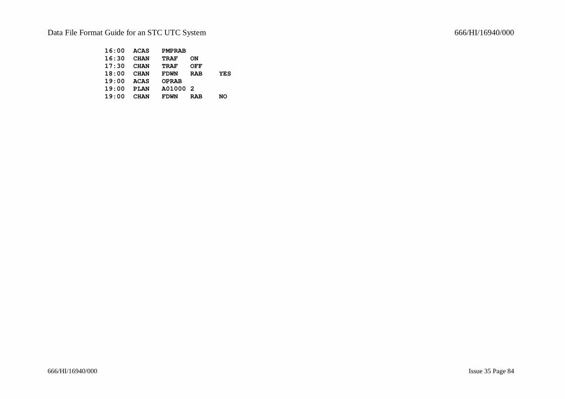
Data File Format Guide for an STC UTC System 666/HI/16940/000
666/HI/16940/000 Issue 35 Page 84
16:00 ACAS PMPRAB16:30 CHAN TRAF ON17:30 CHAN TRAF OFF18:00 CHAN FDWN RAB YES19:00 ACAS OPRAB19:00 PLAN A01000 219:00 CHAN FDWN RAB NO

Data File Format Guide for an STC UTC System 666/HI/16940/000
666/HI/16940/000 Issue 35 Page 85
8. TERMINAL DATA FILE - TRMCNF.DAT
8.1 Printer dataFormat:
PRINTER=(SCN="scn",PHYSICAL_NAME="name",DESCRIPTION="descr",LOG_PRINTER="log",TYPE=”type’,LANGUAGE="lang",BAUD_RATE='n')
Parameters:scn Printer SCN
name VMS port descriptiondescr A descriptive name for the printer
type The type of printer. It may be one of:1- Compaq hardcopy devices such as LA120,LA100,LA34 etc.
2- PCL level 3 printer such as an HP DeskJet3- for a basic ASCII character only output device
log Whether the printer is a log printer or not. Value may be "YES" or "NO"lang The output language for the printer.
n the baud rate. It may be one of:300
12002400
48009600
19200
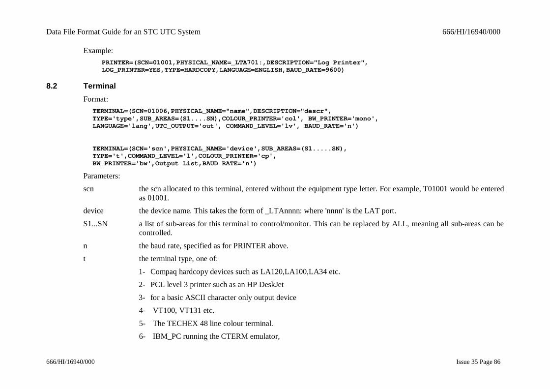
Data File Format Guide for an STC UTC System 666/HI/16940/000
666/HI/16940/000 Issue 35 Page 86
Example:PRINTER=(SCN=01001,PHYSICAL_NAME=_LTA701:,DESCRIPTION="Log Printer",LOG_PRINTER=YES,TYPE=HARDCOPY,LANGUAGE=ENGLISH,BAUD_RATE=9600)
8.2 TerminalFormat:
TERMINAL=(SCN=01006,PHYSICAL_NAME="name",DESCRIPTION="descr",TYPE='type',SUB_AREAS=(S1....SN),COLOUR_PRINTER='col', BW_PRINTER='mono',LANGUAGE='lang',UTC_OUTPUT='out', COMMAND_LEVEL='lv', BAUD_RATE='n')
TERMINAL=(SCN='scn',PHYSICAL_NAME='device',SUB_AREAS=(S1.....SN),TYPE='t',COMMAND_LEVEL='l',COLOUR_PRINTER='cp',BW_PRINTER='bw',Output List,BAUD RATE='n')
Parameters:scn the scn allocated to this terminal, entered without the equipment type letter. For example, T01001 would be entered
as 01001.device the device name. This takes the form of _LTAnnnn: where 'nnnn' is the LAT port.
S1...SN a list of sub-areas for this terminal to control/monitor. This can be replaced by ALL, meaning all sub-areas can becontrolled.
n the baud rate, specified as for PRINTER above.t the terminal type, one of:
1- Compaq hardcopy devices such as LA120,LA100,LA34 etc.2- PCL level 3 printer such as an HP DeskJet
3- for a basic ASCII character only output device4- VT100, VT131 etc.
5- The TECHEX 48 line colour terminal.6- IBM_PC running the CTERM emulator,
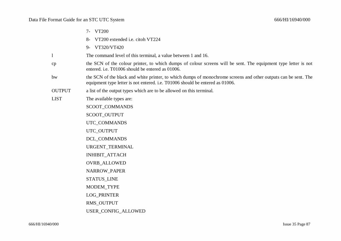
Data File Format Guide for an STC UTC System 666/HI/16940/000
666/HI/16940/000 Issue 35 Page 87
7- VT200
8- VT200 extended i.e. citoh VT2249- VT320/VT420
l The command level of this terminal, a value between 1 and 16.cp the SCN of the colour printer, to which dumps of colour screens will be sent. The equipment type letter is not
entered. i.e. T01006 should be entered as 01006.bw the SCN of the black and white printer, to which dumps of monochrome screens and other outputs can be sent. The
equipment type letter is not entered. i.e. T01006 should be entered as 01006.OUTPUT a list of the output types which are to be allowed on this terminal.
LIST The available types are:SCOOT_COMMANDS
SCOOT_OUTPUTUTC_COMMANDS
UTC_OUTPUTDCL_COMMANDS
URGENT_TERMINALINHIBIT_ATTACH
OVRB_ALLOWEDNARROW_PAPER
STATUS_LINEMODEM_TYPE
LOG_PRINTERRMS_OUTPUT
USER_CONFIG_ALLOWED
Data File Format Guide for an STC UTC System 666/HI/16940/000
666/HI/16940/000 Issue 35 Page 88
The list should be entered as:
Output type=YES/NOwith commands separated by commas. The default value is NO.
Example:TERMINAL=(SCN=01006,PHYSICAL_NAME=_LTA703:,DESCRIPTION="Bus Priority",TYPE=IBM_PC, SUB_AREAS=ALL,COLOUR_PRINTER=01005, BW_PRINTER=01003,LANGUAGE=ENGLISH, UTC_OUTPUT=YES, COMMAND_LEVEL=01,BAUD_RATE=9600)
8.3 Modem PortsFormat :
MODEM = (DEVICE = 'device', CPU = 'c', SPEED = 'n')
Parameters :
device the device. Takes the form of _TXA'm': where 'm' is the terminal number, or _OPA0: for the console.c the processor number. H01000 would be 1.
n the baud rate, specified as for Printer, see Section 8.1.Example :
MODEM = (DEVICE = _TTA2:, CPU = 1, SPEED = 2400)
8.4 Dial-up UsersFormat:
DIALUP=(USR_ID='id',PASSWORD='pw',PHONE_NO='phone',SUB_AREAS=(S1...SN),TYPE='t',COLOUR_PRINTER='cp',BW_PRINTER='bw',BAUD_RATE='n',Output List,COMMAND_LEVEL='l')
Parameters:id the user identification name, as a string of 6 to 12 alphanumeric characters.
pw the password associated with the user identification, as a string of 6 to 12 alphanumeric characters.

Data File Format Guide for an STC UTC System 666/HI/16940/000
666/HI/16940/000 Issue 35 Page 89
phone the dial-back phone number as a numeric string up to 30 digits. If the terminal is not defined as dial-back, then NOshould be entered.
n the baud rate, specified as for PRINTER in PRI.
l The command level of this terminal, a value between 1 and 16.cp the SCN of the colour printer, to which dumps of colour screens will be sent. The equipment type letter is not
entered. i.e. T01006 should be entered as 01006.bw the SCN of the black and white printer, to which dumps of monochrome screens and other outputs can be sent. The
equipment type letter is not entered. i.e. T01006 should be entered as 01006.OUTPUT a list of the output types which are to be allowed on this terminal.
LIST The available types are:- SCOOT_COMMANDS
- SCOOT_OUTPUT- UTC_COMMANDS
- UTC_OUTPUT- DCL_COMMANDS
- URGENT_TERMINAL- OVRB_ALLOWED
- NARROW_PAPER- STATUS_LINE
- RMS_OUTPUT- USER_CONFIG_ALLOWED
The list should be entered as:
Output type=YES/NO
Data File Format Guide for an STC UTC System 666/HI/16940/000
666/HI/16940/000 Issue 35 Page 90
with commands separated by commas. The default value is NO.
Example:DIALUP=(USR_ID=ABCDEFGH,PASSWORD=MANAGER,SUB_AREAS=ALL,PHONE_NUMBER=0712123355,COLOUR_PRINTER=01007,BW_PRINTER=01006,TYPE=VT320,DCL_COMMANDS=NO,SCOOT_COMMANDS=YES,SCOOT_OUTPUT=YES,UTC_COMMANDS=NO,COMMAND_LEVEL=3,STATUS_LINE=YES,BAUD_RATE=9600)
8.5 Daylight Saving TimeFormat:
DST=('date1','date2')
Parameters:date1 the first day at which daylight saving time, or local summer time, begins. The system clock has one hour added at
1am of that day. The date descriptor is in the form dd-mmm-yy where :dd = day (01, 02, ...)
mmm = month (JAN, FEB, ...)yy = year (01, 02, ...)
Note: If “NONE” is entered for the start date the System will automatically calculate the start and enddates using the rules which are defined within POSIX.
date2 the day at which summer time ends. The system clock has one hour taken off at 2am of that day. The same formatas date1 is used. date2 must be later than date1.
NOTE: Both dates must occur in the same year. No double summer time is available.Example:
DST=(25-MAR-91,28-OCT-91)
8.6 System PrinterFormat:
SYSTEM_PRINTER=(<TERMINAL SCN>)
Data File Format Guide for an STC UTC System 666/HI/16940/000
666/HI/16940/000 Issue 35 Page 91
Parameters:
TERMINAL The SCN of the terminal assigned to the system printer, entered withoutSCN the equipment type letter. For example T01002 should be entered as 01002.
Example:SYSTEM_PRINTER=(01001)

Data File Format Guide for an STC UTC System 666/HI/16940/000
666/HI/16940/000 Issue 35 Page 92
9. PLAN FORMATSThe plan formats are described in the Plan Preparation Handbook, reference 1.3.11.

Data File Format Guide for an STC UTC System 666/HI/16940/000
666/HI/16940/000 Issue 35 Page 93
INDEX
(UTMC Outstation ................................................ 17Analogue Sensor ................................................... 58Analogue Sensor Group ........................................ 59APS
Long Queue Groups ......................................... 41Occupancy Groups ........................................... 42Plan Masks ....................................................... 39Priorities .......................................................... 39Short Queue Groups ......................................... 41Volume Groups ................................................ 42
Archive FileLifetime Data ................................................... 12
AREDAT ............................................................. 70Aspect Data .......................................................... 58BEGGRP .............................................................. 59BEGQUE ............................................................. 31BITDAT .......................................................... 18, 23BUSDAT......................................................... 72, 77Car Park ............................................................... 32
Queueing Time................................................. 38Car Park Sign ....................................................... 34
Group Lists Data .............................................. 35CNTDAT ............................................................. 36CONAPS .............................................................. 42Control Bit Formats
Intersection ...................................................... 18Pelican ............................................................. 24
Count Detector ..................................................... 36Count Detector File, Car Park Occupancy Lifetime and Other Data ................... 11CPSDAT .............................................................. 34CPSGRP ............................................................... 35CRPDAT .............................................................. 32Data Word Formats
Pelican ............................................................. 24DATBIT .......................................................... 18, 23DEFSTG .............................................................. 65
DESCRIPTION ....................................................... 9DETDAT ........................................................ 72, 79DIALUP ............................................................... 88Digital IO Wall Map Word Data ............................ 55DIVDAT ............................................................... 43Diversion
Automatic Selection Masks Data ....................... 49Congestion Group Automatic Selection ............. 50Day Sectors ...................................................... 47Dependent Rule Tables ..................................... 49Long Queue Groups Automatic Selection .......... 51Plan Delay Switching Timetables ...................... 48Plan Diversion Rule Tables ............................... 47Short Queue Groups Automatic Selection .......... 52Sign Data .......................................................... 44Volume Group Automatic Selection .................. 52
Diversion Data ...................................................... 43Diversion Lists ...................................................... 45Diversion Sign
Aspect Data ...................................................... 45DIVPLN ......................................................... 47, 48DVDYSC .............................................................. 47DVS ...................................................................... 45EQPDAT .............................................................. 72Fault Code............................................................. 56FBACK ................................................................. 67FILARC ................................................................ 12FILLIF .................................................................. 11FOG Sub-area ....................................................... 55GRPSNS ............................................................... 59GWVSCN ............................................................. 63HRDSCN .............................................................. 61INTREQ ......................................................... 43, 47IRN ......................................................................... 8ISNDAT ......................................................... 19, 20Junction ................................................................ 22
Data File Format Guide for an STC UTC System 666/HI/16940/000
666/HI/16940/000 Issue 35 Page 94
LNKDAT ............................................................. 72LNKSTG ......................................................... 72, 78NCIG ................................................................... 68NMCDAT ............................................................ 63NMCS .................................................................. 63NODSCN ............................................................. 62OCCDAT ............................................................. 38Occupancy Data .................................................... 38OMU .................................................................... 63OMUSCN............................................................. 63Once a Week Events ............................................. 83OSN ....................................................................... 9PADDAT ............................................................. 36Pay and Display .................................................... 36PBITDT ............................................................... 24PDTBIT ............................................................... 24PELDAT .............................................................. 25Pelican.................................................................. 28
Data Word Formats .......................................... 24Plan ...................................................................... 92
formats ............................................................. 92Plan Preparation Handbook ................................... 92PLNAPS ............................................................... 39PLNDAT .............................................................. 29QUE ..................................................................... 31QUEALR ............................................................. 31QUEDAT ............................................................. 30Queue Detector ..................................................... 30
Alarm Inhibit Data ........................................... 31Group Lists ...................................................... 31
REGCPU .............................................................. 62REGDAT ............................................................. 71REMDAT ............................................................. 53
Remote Request .................................................... 53Reply Bit Formats
Intersection ....................................................... 20Pelican.............................................................. 25
Ripple Diversion Lists ........................................... 46SCN
Sub-Area .......................................................... 62SECSTG ............................................................... 68Single Shot Events ................................................ 83SNSDAT............................................................... 58SOFDET ......................................................... 72, 77Special Facility ...................................................... 29
Enable by Plan Data .......................................... 30STGDAT .............................................................. 72SUBCPU............................................................... 61SUBSCN............................................................... 62SYSDAT........................................................... 9, 57TC 8 Outstation ..................................................... 15TC12 ................................................................. 9, 55
Outstation ......................................................... 16TC8......................................................................... 9Telecommand 12 PC ....................................... 14, 61TERMINAL .......................................................... 85Tidal Flow............................................................. 57TIDASP .......................................................... 57, 58TIDDAT ............................................................... 57Timetable Plans Only ............................................ 29TIMTOL ............................................................... 64User Defined Data ................................................. 55VOLAPS............................................................... 43WALDAT ............................................................. 55Wall Map .............................................................. 56WALWRD ............................................................ 55