Operations and Maintenance Manual - Microsemi
85
SyncSystem 4380A Operations and Maintenance Manual Feb 2016 Part Number: 098‐00723‐000 Manual updates are available at: www.microsemi.com/ftdsupport
Transcript of Operations and Maintenance Manual - Microsemi

SyncSystem
4380A
Operations and Maintenance
Manual Feb 2016
Part Number: 098‐00723‐000
Manual updates are available at: www.microsemi.com/ftdsupport


DOC 4380A
4380A O & M Manual
i 098-00723-000– Feb 2016 Revision 1.0 SyncSystem 4380A O&M Manual
Manufacturer Information:
Microsemi, Inc
4775 Walnut Street
Suite 1B
Boulder, CO 80301-2579
www.microsemi.com/time
Where to Find Answers to Product and Document Questions
For additional information about the products described in this guide, please contact your Microsemi
representative or your local sales office. You can also contact us on the web at:
www.microsemi.com/ftdsupport.
When this manual is updated the updated version will be available for downloading from Microsemi’s
internet web site. Manuals are provided in PDF format for ease of use. After downloading, you can view
the manual on a computer or print it using Adobe Acrobat Reader. Manual updates are available at:
www.microsemi.com/ftdsupport
What’s New In This Guide
This is the first release of this document.
Related Documents and Information
See your Microsemi representative or sales office for a complete list of available documentation. To order
any accessory, contact the Microsemi Sales Department. See www.microsemi.com/salescontacts/ for sales
support contact information. If you encounter any difficulties installing or using the product, contact
Microsemi Frequency and Time Division (FTD) Services and Support:
U.S.A. Call Center:
including Americas, Asia and Pacific Rim
Frequency and Time Division
3870 N 1st St.
San Jose, CA 95134
Toll-free in North America: 1-888-367-7966
Telephone: 408-428-7907
Fax: 408-428-7998
email: [email protected]
Internet: www.microsemi.com/ftdsupport
Europe, Middle East, and Africa (EMEA) Microsemi FTD Services and Support EMEA
Altlaufstrasse 42
85635 Hoehenkirchen-Siegertsbrunn
Germany
Telephone: +49 700 3288 6435
Fax: +49 8102 8961 533
E-mail: [email protected]
SyncSystem 4380A Operations and Maintenance Manual
Copyright © 2016 Microsemi
Microsemi is a trademark of Microsemi, Inc.
Other product and company names may be trademarks of their respective owners.

DOC 4380A
4380A O & M Manual
ii 098-00723-000– Feb 2016 Revision 1.0 SyncSystem 4380A O&M Manual
Revision History
Revision Description Date Approved
1.0 Initial Release Feb 2016 KWM
DOC 4380A
4380A O & M Manual
iii 098-00723-000– Feb 2016 Revision 1.0 SyncSystem 4380A O&M Manual
Table of Contents 1 General Information ......................................................................................................... 6
1.1 Introduction .......................................................................................................... 6
1.2 Ordering Information ........................................................................................... 6
2 Installation ........................................................................................................................ 8
2.1 Powering on the 4380A ........................................................................................ 8
2.2 Application Start Up ............................................................................................. 8
2.3 Communicating with the 4380A .......................................................................... 8
2.3.1 DHCP ............................................................................................................ 9
2.3.2 Static IP Addresses ....................................................................................... 9
2.3.2.1 Network ..................................................................................................... 9
2.3.2.2 Console Cable ........................................................................................... 9
2.3.3 Setting a Static IP Address .......................................................................... 10
2.3.4 USB Ports .................................................................................................... 10
2.4 Antenna Installation ........................................................................................... 10
2.4.1 Antenna Location ........................................................................................ 11
2.4.2 Setting the Antenna Voltage ....................................................................... 12
2.4.3 Outdoor Antenna Grounding ...................................................................... 13
2.4.4 Antenna Mask Angle .................................................................................. 13
2.4.5 Positioning Modes ...................................................................................... 14
2.4.5.1 Dynamic Position Mode .......................................................................... 14
2.4.5.2 Auto Position Mode ................................................................................ 14
2.4.5.3 Manual Position Mode ............................................................................ 15
2.5 4380A Installation .............................................................................................. 17
2.5.1 Power Supplies ............................................................................................ 17
2.5.2 Input/Output Cards ...................................................................................... 17
2.5.3 4394A (PPS/DC IRIG) ............................................................................... 17
2.5.4 4376A RS-422 PPS ..................................................................................... 19
2.5.5 4394A-ECL (PPS-ECL) .............................................................................. 20
2.5.6 4395B-10 (10MHz) ..................................................................................... 21
2.5.7 4395B-5 (5MHz) ......................................................................................... 22
2.5.8 4395B-1 (1MHz) ......................................................................................... 22
2.5.9 4387A Series (Modulated IRIG/NASA36) ................................................. 22
2.5.10 4396A/4397A 2MHz Output Card .............................................................. 24
2.5.11 4374A T1 (1.544MHz) Output Card .......................................................... 24
2.5.12 4393A Time Interval Counter (TIC) Card .................................................. 24
2.5.13 4383A IRIG Input Card .............................................................................. 25
2.6 Antenna Delay Calibration ................................................................................. 26
2.7 On Time Point (OTP) ......................................................................................... 27
2.8 Using an External Frequency Reference: ........................................................... 27
2.9 Setting the System Time Manually .................................................................... 29
2.9.1 Force Time .................................................................................................. 29
2.9.2 External Reference ...................................................................................... 30
2.9.3 Disable the GNSS Tracking Alarms ........................................................... 30

DOC 4380A
4380A O & M Manual
iv 098-00723-000– Feb 2016 Revision 1.0 SyncSystem 4380A O&M Manual
2.10 User Configuration Files ................................................................................ 30
2.10.1 Factory / Default User Configuration Files ................................................ 30
2.10.2 Diff Command ............................................................................................ 31
2.10.3 FTP and Real-Time (rt) Configuration Files .............................................. 31
2.10.4 System Configuration Files (Syscfg) .......................................................... 33
2.11 Powering the System Off ................................................................................ 34
3. Operations ...................................................................................................................... 35
3.1 Front Panel ......................................................................................................... 35
3.1.1 Power Supply Indicators ................................................................................. 35
3.1.2 Alarm Indicator ............................................................................................... 35
3.1.3 SYNC Indicator .............................................................................................. 35
3.1.4 Outputs Indicator ............................................................................................ 36
3.1.5 Fans ................................................................................................................. 36
3.1.6 Status Pushbutton ........................................................................................... 37
3.2 Rear Panel .......................................................................................................... 37
3.3 Software ............................................................................................................. 38
3.3.1 Current Version .............................................................................................. 38
3.3.2 Software Updates ............................................................................................ 38
3.3.2.1 Flash Card Replacement ............................................................................. 38
3.3.2.2 Remote Software Update ............................................................................ 39
3.3.3 GNSS Firmware Updates ............................................................................... 40
3.4 User Interfaces .................................................................................................... 40
3.4.1 Telnet .............................................................................................................. 40
3.4.1.1 Real Time Data Port (1135) ........................................................................ 41
3.4.1.2 Command Port (1700) ................................................................................. 41
3.4.1.3 Diagnostic Port (1800) ................................................................................ 43
3.4.1.4 Status Port (1900) ....................................................................................... 44
3.4.1.5 Average TIC Data Port (2100) .................................................................... 44
3.4.1.6 Raw TIC Data Port (2101) .......................................................................... 45
3.4.2 File Transfer Protocol (FTP) .......................................................................... 45
3.4.3 Network Time Protocol (NTP) ....................................................................... 46
3.4.4 Simple Network Management Protocol (SNMP) ........................................... 46
3.5 Status Command ................................................................................................ 46
3.6 GNSS Data Logging ........................................................................................... 47
3.6.1 FTP Data Logging .......................................................................................... 47
3.6.2 Real Time Data Logging ................................................................................ 49
3.7 WAAS Satellites ................................................................................................ 50
3.8 System Verification ............................................................................................ 51
4 Theory of Operations ...................................................................................................... 59
4.1 Generation of Timing Signals ............................................................................ 59
4.2 GNSS .................................................................................................................. 59
4.3 Output Signals .................................................................................................... 59
4.4 GNSS Data Collection ....................................................................................... 60
4.5 Startup Sequence ................................................................................................ 60
5 Maintenance ................................................................................................................... 62
5.1 Fan Filter ............................................................................................................ 62

DOC 4380A
4380A O & M Manual
v 098-00723-000– Feb 2016 Revision 1.0 SyncSystem 4380A O&M Manual
5.2 Antenna and Antenna Cable Inspection ............................................................. 62
6 Troubleshooting .............................................................................................................. 63
6.1 Front Panel Indications ....................................................................................... 63
6.2 Alarm Light ........................................................................................................ 63
6.3 Power Supplies ................................................................................................... 63
6.4 Outputs Indicator ................................................................................................ 64
6.5 GNSS Performance ............................................................................................ 66
6.5.1 Poor GNSS Receiver Performance ................................................................. 66
6.5.2 GNSS Not Tracking ........................................................................................ 67
6.6 Internal Clocks ................................................................................................... 68
6.7 External Reference ............................................................................................. 69
6.8 PTD Value is Noisy ............................................................................................ 71
6.9 Over Temperature and Fans ............................................................................... 71
6.10 PPS Outputs .................................................................................................... 72
6.11 IRIG Outputs .................................................................................................. 73
6.12 NASA36 Outputs ............................................................................................ 73
6.13 TIC Measurements ......................................................................................... 74
6.14 Software Update Failure ................................................................................. 74
6.15 Configuration Not Readable ........................................................................... 75
6.16 Communication Problems .............................................................................. 75
6.16.1 LAN ................................................................................................................ 75
6.16.2 USB-to-Serial Adapter (94000-115200) (Command Port) ............................ 75
6.16.3 External Reference Adapter (94001-5071A) .................................................. 75
6.17 Syslog Command ............................................................................................ 75
6.18 System Configuration Issues (syscfg) ............................................................ 76
Appendix A System Specifications ................................................................................................ 77
Appendix B CE Declaration ........................................................................................................... 83
Figures Figure 1 Antenna Location .............................................................................................................11
Figure 2 Antenna Cable ..................................................................................................................12
Figure 3 Rear Panel Output Card Locations ...................................................................................17
Figure 4 Input/Output Cards ...........................................................................................................17
Figure 5 Timing System Diagram ..................................................................................................27
Figure 6 External Frequency Reference .........................................................................................28
Figure 7 4380A Front Panel ...........................................................................................................35
Figure 8 4380A Rear Panel ............................................................................................................37
Figure 9 4380A Rear Panel Connections .......................................................................................38
Tables
Table 1 Power Supply Indicator Status ..........................................................................................35
Table 2 Alarm Indicator .................................................................................................................35
Table 3 Sync Indicator....................................................................................................................36
Table 4 Outputs Indicator ...............................................................................................................36
Table 5 System Command List ......................................................................................................43
Table 6 Maintenance Schedule .......................................................................................................62

DOC 4380A
4380A O & M Manual
6 098-00723-000– Feb 2016 Revision 1.0 SyncSystem 4380A O&M Manual
1 General Information
1.1 Introduction The 4380A Sync System is a state-of-the-art GNSS disciplined time and frequency reference. The low
noise synthesizer (LNS), in conjunction with GNSS measurements and the Rubidium option, provide
outputs that are characterized by the short-term stability of the OCXO and the long-term stability of the
GNSS constellation. Additionally, it provides the user with the capability to enhance the frequency
stability and holdover performance of the unit by using an external cesium (Cs) clock as the reference.
This provides a scalable architecture that allows users to fulfill a wide range of current and future
requirements with a single unit. The 4380A is suitable for a variety of precise time and frequency
applications.
The 1 Pulse per Second (1 PPS) accuracy and frequency stability of the 4380A is further enhanced by using
a dual-frequency (L1/L2) GNSS receiver. The dual-frequency receiver applies corrections to the GNSS
timing signals that remove a significant portion of the errors due to ionospheric delay.
In applications where reliability is a must, the 4380A is capable of operating from an AC (100 – 240VAC,
50-60 Hz) or DC Power 48 VDC (22 to 60 VDC) source and comes with two fully redundant hot
swappable power supplies. The unit is capable of operating from a single supply in the event one of the
two power supplies fails.
1.2 Ordering Information 4380A (Sync System): Standard dual frequency GNSS time and frequency standard. Dual AC input
supplies included. Requires external frequency reference, fiber reference, or internal Rubidium (RB). The
unit does not include any daughter cards (see below) or fiber SFP modules.
4830A-ACAC-G1R: Two AC Input power supplies. 100-240VAC, 50/60Hz with GPS and internal
Rubidium.
4830A-ACDC-G1R: One AC Input power supply, 100-240VAC, 50/60Hz and one DC input power supply
(22 to 60 VDC) with GPS and internal Rubidium.
4830A-DCDC-G1R: Two DC Input power supplies, (22 to 60 VDC) with GPS and internal Rubidium.
Input/Output Cards: The 4380A has a wide selection of input/output cards available:
1. 4376A RS-422 4 Output 1PPS Card
2. 4395B-10 Four Low Phase Noise 10 MHz Sinewave Outputs
3. 4395B-5 Four Low Phase Noise 5 MHz Sinewave Outputs
4. 4395B-1 Four Low Phase Noise 1 MHz Sinewave Outputs
5. 4394A: Programmable PPS and DC IRIG Module. Users can define the signal types and
operating parameters. Default set up is two 1PPS Outputs (Ports 1 and 2) and two DC IRIG
Outputs (Ports 3 and 4) (Default Timecode = B000)
6. 4394A-ECL Two Programmable differential PPS-ECL Outputs
7. 4387A Four Modulated IRIG Outputs (Default Timecode = B120) or NASA36.

DOC 4380A
4380A O & M Manual
7 098-00723-000– Feb 2016 Revision 1.0 SyncSystem 4380A O&M Manual
8. 4387A-1V Four 1V Modulated IRIG Outputs (Default Timecode = B120) or NASA36
9. 4387A-6V Four 6V Modulated IRIG Outputs (Default Timecode = B120) or NASA36
10. 4396A/4397A Four 2.048MHz (E1) outputs that comply with ITU-T Rec. G.703
11. 4372A-T Four input/output single mode fiber optic module for supplying signals to a TSC-4340
or 4380A
12. 4393A Four Channel TIC Card. Users can measure the 1PPS of up to four different devices
relative to the internal clock and obtain these measurement results in real time.
13. 4383A IRIG Input Card. Users can set the system time manually using an IRIG Time Source.
Ports 1 and 2 support DC IRIG and Ports 3 and 4 support AM IRIG.
Options:
94000-115200 USB Console Cable: Allows users to connect to the system Command Port via a serial
cable.
94001-5071A USB External Reference Communication Cable: Provides a serial communications port
to an external frequency reference (i.e. 5071A).
94020: Rail Kit for Racks 20” to 32” deep
94021: Rail Kit for Racks 24” to 30” deep
92000: L1 L2 GNSS Antenna
9200-12: 12dB inline amplifier
9200-21: 21dB inline amplifier
9201-TT: Lightning Arrestor
Notes:
1. Antenna cables sold separately.
2. All units include network time protocol (NTP), Ethernet control, and data logging capabilities.
3. Contact Microsemi (www.microsemi.com) for current pricing and availability.
4. 94000-115200 and 94001-5071A are DTE devices; this may require the use of a null modem serial cable.

DOC 4380A
4380A O & M Manual
8 098-00723-000– Feb 2016 Revision 1.0 SyncSystem 4380A O&M Manual
2 Installation The 4380A provides a number of features which may require additional setup and this section provides a
guideline for the basic setup. After completing this section, the 4380A will produce timing outputs to the
coarse calibration accuracies specified in Appendix A. The 4380A is designed to be quickly and easily
integrated with other system components. Just a few steps are required in setting up the system so that it
will begin producing accurate timing outputs. In order to set the system up, users will need to power up the
system and set up communications in order to have access to the system command port.
2.1 Powering on the 4380A Apply power to the system by supplying input power to at least one of the two power supplies. When
power is applied to the 4380A the front panel will go through a self test and then the 4380A will begin
booting up.
Note: If power is applied to both power supplies, the Status Indicator on the front panel of both power
supplies should be green. If power is applied to only one of the two supplies, then the power supply
without input power should have a red Status Indicator and the units Alarm Indicator should be red.
Note: The 4380A front panel Power-On Self Test (POST) will occur even if the software flash has been
removed from the unit.
A. The Date/Time display will sequentially test each segment on each individual position within the
display.
B. One at a time, each position of the display will display the number 8 starting from the far left and
working to the right.
C. Each LED below the Date/Time Display (Alarm, Sync, & Output) will be turned on one at a time
starting from the left to right. As each LED is tested it will be green, then red, and then turn off
with the exception of the Sync indicator, this indicator will turn red, then green, then off.
D. The Date/Time display will then display “-9876543210” on the front panel.
E. Lastly the Date/Time display will have a “-” in the center of each position in the display.
F. When the unit starts the application, the Alarm and Sync lights will turn RED. The Outputs
indicator will remain red until NTP is locked and the outputs are turned on.
Caution: The default antenna supply voltage is ZERO. If the antenna requires power from the 4380A to
operate, the system will stay in this mode until the antenna is properly configured. This prevents the
system from potentially damaging any antennas until the antenna supply voltage is set properly by the end
user.
2.2 Application Start Up Once the application has started, the front panel display will display a dash in the center of each segment.
As the application loads the segments will move to the bottom, blank, top, then center until the system has
been able to set the date and time. Refer to the Software Users Guide for more information.
2.3 Communicating with the 4380A Operators are capable of communicating with the system through a LAN connection or via one of the USB
Ports when using 94000-115200 USB to Serial cable to access the command port.

DOC 4380A
4380A O & M Manual
9 098-00723-000– Feb 2016 Revision 1.0 SyncSystem 4380A O&M Manual
2.3.1 DHCP The 4380A runs DHCP by default and will therefore automatically be assigned an IP address if it is
connected to a network with a DHCP server. The 4380A will display the current IP address assigned to the
unit in the Date/Time display after pressing and releasing the Display pushbutton on the front panel. Users
can use this IP Address to access the systems command port.
Note: If the LAN Cable is not connected or the unit does not obtain an IP Address from a DHCP Server,
an IP Address is not assigned and the front panel display button will not display an IP address for the
system. Once the LAN cable is connected to the unit, it will automatically attempt to obtain an IP address
from a DHCP Server. If this does not work you may need to power cycle the unit.
2.3.2 Static IP Addresses If you require a Static IP Address there are two options to set the network parameters in the system.
2.3.2.1 Network If the network has a DCHP Server you can obtain the IP Address (ip addr) by pressing and releasing the
Display pushbutton on the front panel. Telnet into the system using “telnet ip addr 1700”. Once the
“4380A>” prompt is displayed run the network_config command to manually configure the IP address for
the unit. See Section (2.2.3).
If the network does not have a DHCP Server, press and hold the front panel display pushbutton for ~10
seconds until the display shows the IP Address of 192.168.0.1. This temporarily sets the IP Address of the
unit. Telnet into the system using “telnet 192.168.0.1 1700”. Once the “4380A>” prompt is displayed use
the network_config command to manually configure the IP address for the unit. (See section 2.3.3).
Note: If the LAN Cable is removed and reconnected the unit will attempt to obtain an IP Address from the
DHCP Server. If the default static IP Address (192.168.0.1) was set it may get reset. Press the Display
Button on the front panel again to make sure the IP Address is still set. If not, press and hold the button
until the default static IP Address is set again.
2.3.2.2 Console Cable This feature allows local users to set the unit up without having to access the system via the network.
Connect a terminal to one of the USB ports on the rear panel using the USB to Serial adapter cable (94000-
115200). Changes can be made using any terminal program (e.g., HyperTerm, TeraTerm) from the serial
port of a computer/terminal. The communication settings are 115200 Baud, No Parity, 8 Data Bits, and 1
Stop Bit. Once connectivity is established, the user will see the 4380A> command prompt. Execute the
network_config command to set the IP Address, Netmask, Broadcast IP, and/or Default Gateway for the
system if you are using a static IP Address. See Section (2.3.3).
Note: We recommend that the USB-to-Serial Adapter (94000-115200) is installed in one of the two USB
ports when the system is powered on. If not, you may need to power the system down, plug the cable in
and re-apply power. The USB/Serial Cables are programmed to provide users access to the command port
(94000-115200) or to communicate with a 5071A Cesium Clock (94001-5071A). These cables are NOT
interchangeable.
Caution: By default, pressing and holding the Display pushbutton on the front panel for ~10 seconds will
reset the IP address to the default of 192.168.0.1. The default IP address will display on the front panel
after it is set. If the button is held down too long and the IP Address is set to the default by mistake, you
may be able to clear this by pulling the LAN connection on the rear panel and plugging the connector back
in. If not, power-cycle the unit to restore the proper network settings. This front panel IP reset feature can
be disabled using the frontpanel_button command. Users are cautioned that the reset feature is ON by
default and must be turned off if this is not the desired behavior.

DOC 4380A
4380A O & M Manual
10 098-00723-000– Feb 2016 Revision 1.0 SyncSystem 4380A O&M Manual
2.3.3 Setting a Static IP Address Use the following steps to set the IP Address on the 4380A.
A. Telnet into the system telnet ip addr 1700 or connect to the unit via the Console Cable and the
4380A> prompt should appear.
B. Use the network_config command and options to set the system to the desired network settings. network_config --mode <DHCP|static> --ip <ip addr> --mask <mask> --broadcast <broadcast> --gateway <gateway>]
[Example] network_config --mode static --ip 192.168.1.50 --mask 255.255.255.0 --broadcast 192.168.1.255 --gateway 192.168.1.1
C. These network settings will take effect immediately. Users should see the following: <working> ……….. Once timed out, the network connection will drop.
D. Users connected via the network will need to reconnect to the system using the newly assigned
static IP Address. Users do not need to save these changes; they are automatically stored on the
system. The 4380A will start up with the new settings each time it is rebooted or power cycled.
E. Users can also view the current network settings using the network command. This will display
the current user settings. 4380A>network [mode] static[mode] static[mode] static[mode] static [static] [broadcast] 192.168.150.255 [default_gateway] 192.168.150.1 [ip] 192.168.150.61 [netmask] 255.255.255.0 [OK] 2015-08-05T14:23:28Z
2.3.4 USB Ports The USB ports on the rear panel allow:
• Users to access the command port (94000-115200). See section 2.3.2.2. Users can set the IP
Address on the box following the instructions in section 2.3.3.B-C. The system will
automatically connect to the command port and provide the 4380A> command prompt.
• The 4380A to communicate with a 5071A Cesium Clock (94001-5071A). See section 2.7.
Note: Microsemi recommends if you are going to use these cables that the cables should be plugged into
the unit when it is powered on.
2.4 Antenna Installation Installing the antenna properly requires careful planning. The antenna location itself must be selected
based solely on the ability to reliably receive the GNSS signal. This should be one of the primary factors in
selecting the installation location of this unit depending on the length of the antenna cable.
Note: The antenna cable should have less than 10 dB of loss at 1.5 GHz. If this is not possible due to the
cable type or length of cable then additional in-line amplifiers will be need to be installed or you will need a
cable type with less loss.
The antenna included with the 4380 has a 5/8” coarse threaded mounting screw hole on the bottom. This
threaded hole allows the antenna to be easily and securely mounted on a 5/8” coarsely threaded rod.

DOC 4380A
4380A O & M Manual
11 098-00723-000– Feb 2016 Revision 1.0 SyncSystem 4380A O&M Manual
Threaded rods are available at most hardware stores and will need to be mounted securely to the side of a
building or other stationary object. Once the rod is properly secured it will provide a stable mount for the
antenna.
2.4.1 Antenna Location The 4380A is typically mounted in a standard 19” equipment rack, but the unit may also be operated from a
bench top. No matter which location is chosen, the installation location should be selected keeping in mind
that access to a suitable antenna location will be necessary for proper operation.
A. Placement of the GNSS antenna is extremely important. It should be placed so that it has clear
view of as much sky as possible. Any obstructions such as antennas, large metal objects, or
buildings will limit the performance of the 4380A. The GNSS antenna should have an
unobstructed line of sight to the sky. (See Figure 1.)
B. In selecting a location for the antenna, its proximity to the 4380A should also be considered.
Ideally, the antenna will be close enough to the 4380A so loss through the antenna cable is
minimized.
WARNING: An outside antenna system should not be located in the vicinity of overhead power
lines or other electric light or power circuits, or where it can fall into such power lines or circuits.
When installing an outside antenna system, extreme care should be taken to keep it from touching
such power lines or circuits as contact with them might be fatal.
AVERTISSEMENT: Un système extérieur d'antenne ne devrait pas être situé à proximité des
lignes à haute tension aériennes ou d'autres circuits de lumière électrique ou de puissance, ou où il
peut tomber dans de tels lignes à haute tension ou circuits. En installant un système extérieur
d'antenne, le soin extrême devrait être pris pour le garder de toucher de tels lignes à haute tension
ou circuits comme entrent en contact avec eux force soyez mortel.
Figure 1 Antenna Location
C. Once a suitable antenna location has been identified, it is necessary to ensure that the GNSS signal
that reaches the 4380A is of suitable quality. The unit requires a minimum of 15dB gain from the
antenna gain combined with the amount of loss in the antenna cable. The antenna included with
the 4380A has 25dB of gain so the total cable losses in the system must not exceed 10 dB at 1.5
GHz. If you are using a different antenna please ensure the antenna gain combined with the cable
loss will provide sufficient signal strength for the 4380A.
D. If the location of the antenna dictates that a longer cable must be used, then a line amplifier will
need to be inserted into the signal path or you will need to run an antenna cable with less loss. A
line amplifier is a device used to amplify the GNSS signal to overcome the losses resulting from
longer cable runs. In selecting a line amplifier, it is necessary to make sure that it provides an
adequate amount of gain and that it operates from 1200MHz to 1600MHz.
E. The amount of gain required from a line amplifier can be calculated by knowing the total loss of
the antenna cables being used. The signal loss due to a cable varies depending upon the frequency
DOC 4380A
4380A O & M Manual
12 098-00723-000– Feb 2016 Revision 1.0 SyncSystem 4380A O&M Manual
of the signal. For the purposes of GNSS antennas, the cable loss should be calculated at
1500MHz. The manufacturer of the cable being used should be able to provide an estimate of the
cable loss at 1500MHz. Once the cable loss is known, it can be inserted into Equation 2-1 to
calculate the required gain of the line amplifier.
12100
)(_*)100/(_)(_ −=
ftLengthCableftdBLossCabledBGainMIN Eq. 2-1.
F. The MIN_Gain value in Equation 2-1 serves as the minimum gain required from the line amplifier
being used. It is possible to use amplifiers with a slightly higher gain than the minimum value but
it will not improve the performance of the system. Using amplifiers with significantly higher gain
values can also cause degradation of the GNSS signal because it overdrives the input of the GNSS
receiver.
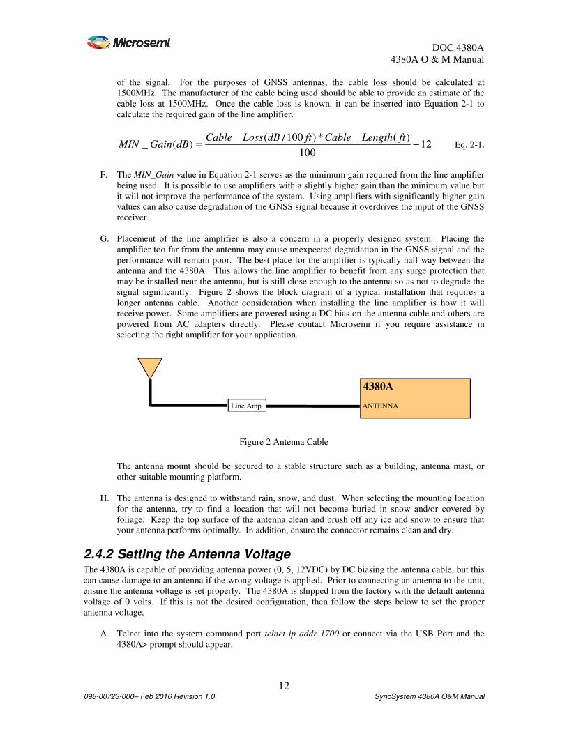
G. Placement of the line amplifier is also a concern in a properly designed system. Placing the
amplifier too far from the antenna may cause unexpected degradation in the GNSS signal and the
performance will remain poor. The best place for the amplifier is typically half way between the
antenna and the 4380A. This allows the line amplifier to benefit from any surge protection that
may be installed near the antenna, but is still close enough to the antenna so as not to degrade the
signal significantly. Figure 2 shows the block diagram of a typical installation that requires a
longer antenna cable. Another consideration when installing the line amplifier is how it will
receive power. Some amplifiers are powered using a DC bias on the antenna cable and others are
powered from AC adapters directly. Please contact Microsemi if you require assistance in
selecting the right amplifier for your application.
The antenna mount should be secured to a stable structure such as a building, antenna mast, or
other suitable mounting platform.
H. The antenna is designed to withstand rain, snow, and dust. When selecting the mounting location
for the antenna, try to find a location that will not become buried in snow and/or covered by
foliage. Keep the top surface of the antenna clean and brush off any ice and snow to ensure that
your antenna performs optimally. In addition, ensure the connector remains clean and dry.
2.4.2 Setting the Antenna Voltage The 4380A is capable of providing antenna power (0, 5, 12VDC) by DC biasing the antenna cable, but this
can cause damage to an antenna if the wrong voltage is applied. Prior to connecting an antenna to the unit,
ensure the antenna voltage is set properly. The 4380A is shipped from the factory with the default antenna
voltage of 0 volts. If this is not the desired configuration, then follow the steps below to set the proper
antenna voltage.
A. Telnet into the system command port telnet ip addr 1700 or connect via the USB Port and the
4380A> prompt should appear.
4380A
Line Amp
Figure 2 Antenna Cable
ANTENNA

DOC 4380A
4380A O & M Manual
13 098-00723-000– Feb 2016 Revision 1.0 SyncSystem 4380A O&M Manual
B. At the 4380A> prompt, type settings gnss and press enter, this will display the user configurable
GNSS settings for the unit to view and verify the current voltage being supplied to the antenna is
correct. 4380A>settings gnss [antenna_delay] 0.000000000000000e-00 [antenna_voltage] [antenna_voltage] [antenna_voltage] [antenna_voltage] 0000....000000000000000000e+000000000000000e+000000000000000e+000000000000000e+00000 [datum] wgs84 [mask_angle] 1.000000000000000e+01 [positioning] [auto_hours] 1.200000000000000e+01 [manual_position] [altitude] 1.963225000000000e+02 [latitude] 3.992277661000000e+01 [longitude] -7.758567306000000e+01 [mode] auto [tracking_timeout] 1800 [OK] 2015-08-05T14:28:57Z
C. To change the value, type antenna_voltage and set the desired value (0, 5, or 12) and press enter.
The system should respond with “OK”. 4380A>antenna_voltage 12antenna_voltage 12antenna_voltage 12antenna_voltage 12 [OK] 2015-08-05T14:30:16Z
Note: If you enter an incorrect value you will get the following error message: 4380A>antenna_voltage 3 Usage : antenna_voltage <0 | 5 | 12> [ERROR] 2015-08-05T14:30:53Z
D. You can verify the setting is correct by typing settings gnss:antenna_voltage and pressing enter,
this will display the current antenna voltage setting. 0 VDC 0.0000000000000000e+00 5 VDC 5.0000000000000000e+00 12VDC 1.2000000000000000e+01
The antenna voltage setting can also be verified using a voltmeter. To verify the antenna voltage,
apply the probes to the ANTENNA connector on the rear panel. The center conductor should be
at a higher potential than the 4380A chassis. This voltage reading indicates the voltage being
provided to the antenna. If no voltage is present, then the antenna is not being powered by the
4380A.
E. If this setting is correct, type save to save the current user default configuration on the system to
ensure the system provides the proper antenna voltage after a reboot or power cycle.
2.4.3 Outdoor Antenna Grounding If an outside antenna is connected to the 4380A, be sure the antenna is grounded so as to provide some
protection against voltage surges and built-up static charges. Article 810 of the National Electrical Code,
ANSI/NFPA 70 provides information with regard to proper grounding of the mast and supporting structure,
grounding of the lead-in wire to an antenna discharge unit, size of grounding connectors, location of
antenna discharge unit, connection to grounding electrodes, and requirements for the grounding electrode.
2.4.4 Antenna Mask Angle Adjustment of the antenna mask angle may be necessary for installations with severe multipath problems.
The mask angle of the antenna refers to the elevation angle above the horizon at which all satellites above it
are tracked. It may be possible to track satellites below the mask angle, but the data is intentionally omitted
because it is unreliable. Installations with severe multi-path problems may find that they get better timing
performance out of the 4380A when using a higher mask angle. To set the mask angle, access the system

DOC 4380A
4380A O & M Manual
14 098-00723-000– Feb 2016 Revision 1.0 SyncSystem 4380A O&M Manual
via the command port and use the mask_angle command to set the desired mask angle for the receiver.
Mask angle value is in degrees. 4380A>mask_angle 10 [OK] 2015-08-05T15:05:12Z
You can verify the current value of the mask angle by sending the settings gnss:mask_angle command. 4380A>settings gnss:mask_angle 1.000000000000000e+01 [OK] 2015-08-05T15:04:43Z
If this setting is correct, type save to save the current user default configuration on the system to ensure the
system uses the proper mask angle after a reboot or power cycle.
2.4.5 Positioning Modes The 4380A offers three different modes for determining the antenna position and determining receiver
operation: dynamic, auto, and manual.
2.4.5.1 Dynamic Position Mode The Dynamic mode is typically used for systems located on mobile platforms.
Note: The system default mode is dynamic. Users at static locations should change this to auto or manual
based on the information provided below.
2.4.5.2 Auto Position Mode The Auto mode is recommended for static locations where the antenna location has not been surveyed.
When using the Auto mode, the 4380A will automatically determine the location of its antenna. It does this
by averaging its calculated position solutions over a period specified by the auto_hours parameter. The
factory default for the position period is 12 hours. It is recommended that the auto positioning period
should be set to at least 4 hours. Once the position_period expires, the 4380A will enter the fixed position
mode (status gnss:position:fixed). Fixing the antenna position reduces the noise of the GNSS
measurements and increases the frequency stability of the timing outputs.
To set the positioning mode to auto, use the position_mode command on the command port. 4380A>position_mode auto [OK] 2015-08-05T15:26:06Z
To set the positioning period, use the position_period command. If not specified, the value will be in
hours. Users can set this value to minutes using m after the value. 4380A>position_period 12 [OK] 2015-08-05T15:26:06Z
Select the proper datum, WGS84 (default) or NAD83, using the datum command. 4380A>datum wgs84 [OK] 2015-08-05T15:28:14Z
Use the settings gnss command to verify the correct datum is being used. 4380A>settings gnss [antenna_delay] 2.650000000000000e-07 [antenna_voltage] 1.200000000000000e+01 [datum] wgs84[datum] wgs84[datum] wgs84[datum] wgs84 [mask_angle] 1.000000000000000e+01 [positioning]

DOC 4380A
4380A O & M Manual
15 098-00723-000– Feb 2016 Revision 1.0 SyncSystem 4380A O&M Manual
[auto_hours] 1.200000000000000e+01[auto_hours] 1.200000000000000e+01[auto_hours] 1.200000000000000e+01[auto_hours] 1.200000000000000e+01 [manual_position] [altitude] 1.963545000000000e+02 [latitude] 3.992275796000000e+01 [longitude] -7.758566956000000e+01 [m[m[m[mode] autoode] autoode] autoode] auto [tracking_timeout] 1800 [OK] 2015-08-05T15:27:19Z
If these settings are correct, type save to save the current user default configuration on the system to ensure
the system uses the positioning mode and period after a reboot or power cycle.
Note: If the unit is rebooted, power cycled, or the application is restarted with the positioning mode set to
auto, the system will go through the process of determining its antenna position based on the position
period (auto_hours). Once that period expires, the system will again set itself fixed and use the new
determined solution as the fixed position. It will do this each time this occurs. The [ptd] or UTC offset
value reported by the system will be noisier during the auto position period and will become significantly
quieter when the antenna position is fixed.
In addition to automatically determining its antenna location, the 4380A generates a RINEX (Receiver
INdependent EXchange) format observation file. This file format is a standard used by the GNSS
community and provides all the necessary GNSS measurements for determining the antenna location. The
file can be retrieved from the system by using ftp (login: ftp, password: ftp) to log in and retrieve the file.
The file will be in the “rinex” subdirectory and will have a “.[yy]o” extension where [yy] represents the last
two digits of the current year. Many online processing centers are available (e.g.,
http://www.ngs.noaa.gov/OPUS, http://sopac.ucsd.edu/cgi-bin/SCOUT.cgi) and will process the
observation file free of charge. Doing this improves the position estimate of the antenna and is
recommended for precise time recovery. After this is complete, it is possible to set the position mode to
manual using the coordinates provided by those services.
Note: The receiver has a countdown timer to show the amount of time left (position_period) while in the
auto positioning mode. Once this timer counts to zero, the RINEX file will be generated, the receivers
position (status gnss:position:fixed) will be true, and the [time_remaining] field will no longer be present in
the status message. 4380A>status gnss:auto_positioning [time_remaining] 10 hours, 51 minutes[time_remaining] 10 hours, 51 minutes[time_remaining] 10 hours, 51 minutes[time_remaining] 10 hours, 51 minutes [OK] 2015-08-05T15:32:05Z 4380A>status gnss:position [alt] 1.965699000000000e+02 [fixed] false[fixed] false[fixed] false[fixed] false lat] 3.992275579961000e+01 [lon] -7.758567122127999e+01 [OK] 2015-08-05T15:32:33Z
2.4.5.3 Manual Position Mode If the location of the antenna is known, then the Manual mode should be used. This mode uses the
information provided by the datum, latitude, longitude, and altitude parameters to fix the antenna position
at startup.
Note: This bypasses the auto positioning period and the 4380A will not generate a RINEX observation
file. This mode of operation is recommended ONLY if the antenna position is known. Once you set any of
these three parameters (lat, lon, or alt), the 4380A will automatically go into manual mode.
Caution: If the operator enters the manual position incorrectly, the system will indicate it is tracking
satellites in the status output, however the system may show the gnss status as “not tracking” both in the
status results and on the front panel. To correct this problem ensure the position is entered correctly. If this
does not work, set the unit to the auto position mode and re-survey the antenna position.

DOC 4380A
4380A O & M Manual
16 098-00723-000– Feb 2016 Revision 1.0 SyncSystem 4380A O&M Manual
4380A>status gnss:satellite:number 9999 [OK] 2015-08-05T15:36:14Z 4380A>status gnss:mode:desc trackingtrackingtrackingtracking [OK] 2015-08-05T15:37:27Z
To manually set the antenna position, use the following steps:
A. Select the proper datum, WGS84 (default) or NAD83, using the datum command. 4380A>datum wgs84 [OK] 2015-08-05T15:42:42Z
B. Set the latitude for the antenna using the latitude command. 4380A>latitude 38.46627893094 or 4380A>latitude 38.46627893094N
Note: Default is [N]orth. If you are in the southern hemisphere make sure there is an [S]outh
after the latitude or a (-) before the latitude. 4380A>latitude -38.46627893094 or 4380A>latitude 38.46627893094S
C. Set the longitude for the antenna using the longitude command. 4380A>longitude 77.44086542274004 or 4380A>longitude 77.44086542274004E
Note: Default is [E]ast. If you are in the Western hemisphere make sure there is an [W]est after
the latitude or a (-) before the latitude. 4380A>longitude -77.44086542274004 or 4380A>longitude 77.44086542274004W
D. Set the altitude for the antenna using the “altitude” command. Default value is ellipsoid height
meters. Users can specify the height in feet by using F after the value. 4380A>altitude 51.573999999999998 or 4380A>altitude 169.206037003 F
E. Verify the current settings are correct using the settings gnss command or narrow it down further
with the settings gnss:positioning:manual_position and settings gnss:datum commands. 4380A>settings gnss:positioning:manual_position [altitude] 5.1573999999999998e+01 [latitude] 3.8466278930940000e+01 [longitude] -7.7440865422740004e+01 4380A>settings gnss:datum wgs84wgs84wgs84wgs84 [OK] 2015-08-05T15:43:31Z
The operator also has the option of setting the manual mode and entering all three parameters on the same
command line using the fix_position (current | lat, lon, alt) command. 4380A> fix_position 38.46627893094 -77.44086542274004 51.573999999999998
Warning: If the operator uses this command and does not provide any of the arguments, the unit will set
its position based on the current system status (status gnss:position) value. Doing this may cause accuracy
issues because of position errors.

DOC 4380A
4380A O & M Manual
17 098-00723-000– Feb 2016 Revision 1.0 SyncSystem 4380A O&M Manual
If these settings are correct, type save to save the current position on the system to ensure the system uses
the manual positioning mode after a reboot or power cycle.
2.5 4380A Installation The 4380A is ready for installation into a standard 19" (48.3 cm) rack using either slides or shelves and will
take up 1U of rack space. The 4380A has the following options for the slides:
94020 = Rail Kit, 20-32” Rack Depth
94021 = Rail Kit, 24-30” Rack Depth
2.5.1 Power Supplies The 4380A operates with two power supplies capable of operating on different power sources. The 4365A
(AC Power Supply) and 4366A (DC Power Supply) are available. The 4380A is capable of operating on
one power supply in the event that the other fails or its input source fails. Power Supply #1 is on the left
and Power Supply #2 is on the right when looking at the front of the unit. See Appendix A for the
specifications on the Power Supplies.
2.5.2 Input/Output Cards The 4380A will operate with several different types of input and output cards. These cards can be operated
in any of the six slots. The unit will automatically detect and configure the system based on the card(s)
installed. The card slots are identified by slot number so the operator is capable of identifying the cards
physical location in the chassis. The view below is from the rear of the unit from left to right.
Slot 1 Slot 3 Slot 5
Slot 2 Slot 4 Slot 6
Figure 3 Rear Panel Output Card Locations
Each input/output card typically has four connectors with the port number identified as shown below in
Figure 4. See Appendix A for the specifications of each card.
Port 1 Port 2 Port 3 Port 4
Figure 4 Input/Output Cards
2.5.3 4394A (PPS/DC IRIG) The factory default for this module provides two 1PPS outputs (Outputs 1 and 2) and two DC IRIG (B000)
outputs (Outputs 3 and 4).
The output types are user selectable/programmable. Users can change the signal types (PPS/DC IRIG), the
PPS signal parameters, and the IRIG signal types on individual output ports.
• PPS: Valid PPS settings are 1, 10, 100, 1K, 10K, 100K, and 1M PPS. To set the PPS signal
parameters use the pps command: 4380A> pps [slot#] [port#] [pulse period] [pulse width]
The following example sets the PPS on Slot 1, Port 2 to 1MPPS and the pulse width to 500 ns (1/2
the duty cycle). 4380A>pps 1 2 1e-6 5e-7

DOC 4380A
4380A O & M Manual
18 098-00723-000– Feb 2016 Revision 1.0 SyncSystem 4380A O&M Manual
[OK] 2015-08-05T15:52:31Z
The following rules apply:
1. PERIOD - period of pulse in seconds(max of 1, min of 1e-6)
2. WIDTH - pulse width in seconds (minimum of 5e-7)
3. For PPS Rates where the duty cycle is 10 µs or greater, the pulse_width must be a multiple of
10 µs, at least 10 µs wide, and at most half the duty cycle of the pulse_period.
4. For PPS rates where half the duty cycle is less than 10 µs, the pulse_width must be exactly
one-half the pulse_period. (See example above.)
The system will generate an error message if the values are not correct or entered improperly. Usage: <slot#> <port#> <pulse period> <pulse width> [ERROR] 2015-08-05T15:53:07Z
To verify the settings use the settings hardware:slots:N command (where N=Slot #) to obtain the
current settings for a particular card. 4380A> settings hardware:slots:1 [4394A] [ports] [1] [pps_period] 1.000000000000000e+00 [pps_width] 1.000000000000000e-04 [type] pps [2][2][2][2] [pps_period] 1.000000000000000e+00[pps_period] 1.000000000000000e+00[pps_period] 1.000000000000000e+00[pps_period] 1.000000000000000e+00 [pps_width] 5.000000000000000e[pps_width] 5.000000000000000e[pps_width] 5.000000000000000e[pps_width] 5.000000000000000e----01010101 [type] pps[type] pps[type] pps[type] pps [3] [format] A [signal_word] 3 [type] irig [4] [format] B [signal_word] 0 [type] irig [OK] 2015-08-05T15:51:30Z
• IRIG: Valid DC IRIG Codes are A (000,003,007), B (000,003,007), D002, E002, G002, and
H002. Default is B000. To set the IRIG Code for the individual ports, use the irig command: 4380A> irig [slot#] [port#] [Code A-H] [Code Format <NNN>]
The following example sets the IRIG for Slot 1, Port 3 to A 003. 4380A>irig 1 3 A 003 [OK] 2015-08-05T16:02:16Z
The system will generate an error message if the operator attempts to enter an unsupported or
invalid code.
To verify the settings, use the settings hardware:slots:N command (where N=Slot #) to obtain the
current settings for a particular card. 4380A> settings hardware:slots:1 [4394A] [ports] [1] [pps_period] 1.000000000000000e+00 [pps_width] 1.000000000000000e-04 [type] pps [2] [pps_period] 1.000000000000000e-06 [pps_width] 5.000000000000000e-07 [type] pps [3][3][3][3] [format] A[format] A[format] A[format] A

DOC 4380A
4380A O & M Manual
19 098-00723-000– Feb 2016 Revision 1.0 SyncSystem 4380A O&M Manual
[signal_wo[signal_wo[signal_wo[signal_word] 3rd] 3rd] 3rd] 3 [type] irig[type] irig[type] irig[type] irig [4] [format] B [signal_word] 0 [type] irig [OK] 2015-08-05T16:02:45Z
Note: The system will drop the leading zeros in the signal_word.
To verify the card is working properly, use the status hardware:outputs:slots:N command (where
N=Slot #) to obtain the current settings for a particular card. 4380A>status hardware:outputs:slots:1 [ports] [1] [status] good [2] [status] good [3] [status] good [4] [status] good [power] enabled [type] 4394A [OK] 2015-08-05T16:03:59Z
Warning: The user configuration for the specific output formats are stored on the system itself.
Replacement modules will automatically be configured with the correct output format as long as the
replacement card is installed in the same slot. Moving the output module to a different slot causes the
system to configure the module with the default output format(s) until that card slot is properly configured
by the user.
Avertissement: La configuration d'utilisateur pour les formats spécifiques de rendement sont stockées sur
le système lui-même. Des modules de rechange seront automatiquement configurés avec le format correct
de rendement tant que la carte de rechange est installée dans la même fente. Déplacer le module de
rendement à une fente différente fait configurer le système le module avec les formats de rendement de
défaut jusqu'à ce que ce logement pour carte soit correctement configuré par l'utilisateur.
2.5.4 4376A RS-422 PPS The factory default for this module provides four 1PPS outputs. Users can change the PPS signal
parameters, on individual signal outputs.
Valid PPS settings are 1, 10, 100, 1K, 10K, 100K, and 1M PPS. To set the PPS signal parameters use the
pps command: 4380A> pps [slot#] [port#] [pulse period] [pulse width]
The following example sets the PPS on Slot 1, Port 2 to 1MPPS and the pulse width to 500 ns (1/2 the duty
cycle). 4380A>pps 1 2 1e-6 5e-7 [OK] 2015-08-05T15:52:31Z
The following rules apply:
1. PERIOD - period of pulse in seconds(max of 1, min of 1e-6)
2. WIDTH - pulse width in seconds (minimum of 5e-7)
3. For PPS Rates where the duty cycle is 10 µs or greater the pulse_width must be a multiple of
10 µs, at least 10 µs wide, and at most half the duty cycle of the pulse_period.
4. For PPS rates where half the duty cycle is less than 10 µs, the pulse_width must be exactly
one-half the pulse_period. (See example above.)

DOC 4380A
4380A O & M Manual
20 098-00723-000– Feb 2016 Revision 1.0 SyncSystem 4380A O&M Manual
The system will generate an error message if the values are not correct or entered improperly. Usage: <slot#> <port#> <pulse period> <pulse width> [ERROR] 2015-08-05T15:53:07Z
To verify the settings use the settings hardware:slots:N command (where N=Slot #) to obtain the current
settings for a particular card. 4380A>settings hardware:slots:5 [tsc4376] [ports] [1] [pps_period] 1.000000000000000e+00 [pps_width] 1.000000000000000e-04 [type] pps [2] [pps_period] 1.000000000000000e+00 [pps_width] 1.000000000000000e-04 [type] pps [3] [format] B [pps_period] 1.000000000000000e+00 [pps_width] 1.000000000000000e-04 [type] pps [4] [format] B [pps_period] 1.000000000000000e+00 [pps_width] 1.000000000000000e-04 [type] pps [OK] 2015-02-05T20:36:
To verify the card is working properly, use the status hardware:outputs:slots:N command (where N=Slot
#) to obtain the current settings for a particular card. 4380A>status hardware:outputs:slots:5 [ports] [1] [status] good [2] [status] good [3] [status] good [4] [status] good [power] enabled [type] 4376A [OK] 2015-02-05T20:27:05Z
2.5.5 4394A-ECL (PPS-ECL) This module provides two 1PPS outputs. The output types are user selectable/programmable. Users can
change the PPS signal parameters. Valid PPS settings are 1, 10, 100, 1K, 10K, 100K, and 1M PPS. To set
the PPS signal parameters use the pps command: 4380A> pps [slot#] [port#] [pulse period] [pulse width]
The following example sets the PPS on Slot 1, Port 2 to 1PPS and the pulse width to 10µs. 4380A>pps 1 2 1 1e-5 [OK] 2015-08-05T15:52:31Z
The following rules apply:
1. PERIOD - period of pulse in seconds(max of 1, min of 1e-6)
2. WIDTH - pulse width in seconds (minimum of 5e-7)
3. For PPS Rates where the duty cycle is 10 µs or greater the pulse_width must be a multiple of 10
µs, at least 10 µs wide, and at most half the duty cycle of the pulse_period.

DOC 4380A
4380A O & M Manual
21 098-00723-000– Feb 2016 Revision 1.0 SyncSystem 4380A O&M Manual
4. For PPS rates where half the duty cycle is less than 10 µs, the pulse_width must be exactly one-
half the pulse_period.
The system will generate an error message if the values are not correct or entered improperly. Usage: <slot#> <port#> <pulse period> <pulse width> [ERROR] 2015-08-05T15:53:07Z
To verify the settings, use the settings hardware:slots:N command (where N=Slot #) to obtain the current
settings for a particular card. 4380A> settings hardware:slots:1 [4394] [ports] [1] [pps_period] 1.000000000000000e+00 [pps_width] 1.000000000000000e-04 [type] pps [2][2][2][2] [pps_period] 1.000000000000000e+00[pps_period] 1.000000000000000e+00[pps_period] 1.000000000000000e+00[pps_period] 1.000000000000000e+00 [pps_width] 1.000000000000000e[pps_width] 1.000000000000000e[pps_width] 1.000000000000000e[pps_width] 1.000000000000000e----05050505 [type] pps[type] pps[type] pps[type] pps [3] [format] A [signal_word] 3 [type] irig [4] [format] B [signal_word] 0 [type] irig [OK] 2015-08-05T15:51:30Z
To verify the settings, use the status hardware:outputs:slots:N command (where N=Slot #) to obtain the
current settings for a particular card. 4380A> status hardware:output:slots:1 [4394] [ports] [1] [status] good [2] [status] good [3] [status] n/a [4] [status] n/a [power] enabled [type] 4394A-ECL [OK] 2015-08-05T15:51:30Z
Warning: The user configurations for the specific output formats are stored on the system itself.
Replacement modules will automatically be configured with the correct output format as long as the
replacement card is installed in the same slot. Moving the output module to a different slot causes the
system to configure the module with the default output format(s) until that card slot is properly configured
by the user.
Avertissement: Les configurations d'utilisateur pour les formats spécifiques de rendement sont stockées
sur le système lui-même. Des modules de rechange seront automatiquement configurés avec le format
correct de rendement tant que la carte de rechange est installée dans la même fente. Déplacer le module de
rendement à une fente différente fait configurer le système le module avec les formats de rendement de
défaut jusqu'à ce que ce logement pour carte soit correctement configuré par l'utilisateur
2.5.6 4395B-10 (10MHz) No programming is required for these modules. These modules will also work in any of the 6 card slots.
To verify these cards are working properly, use the status hardware:outputs:slots:N command (N = slot
number) to obtain the current status for a particular card.

DOC 4380A
4380A O & M Manual
22 098-00723-000– Feb 2016 Revision 1.0 SyncSystem 4380A O&M Manual
4380A>status hardware:outputs:slots:3 [ports] [1] [status] good [2] [status] good [3] [status] good [4] [status] good [power] enabled [type] 4395A[type] 4395A[type] 4395A[type] 4395A----10101010 [OK] 2015-08-05T16:06:29Z
2.5.7 4395B-5 (5MHz) No programming is required for these modules. These modules will also work in any of the 6 card slots.
To verify these cards are working properly, use the status hardware:outputs:slots:N command (N = slot
number) to obtain the current status for a particular card. 4380A>status hardware:outputs:slots:4 [ports] [1] [status] good [2] [status] good [3] [status] good [4] [status] good [power] enabled [type] 4395B[type] 4395B[type] 4395B[type] 4395B----5555 [OK] 2015-08-05T16:37:43Z
2.5.8 4395B-1 (1MHz) No programming is required for these modules. These modules will also work in any of the 6 card slots.
To verify these cards are working properly, use the status hardware:outputs:slots:N command (N = slot
number) to obtain the current status for a particular card. 4380A>status hardware:outputs:slots:5 [ports] [1] [status] good [2] [status] good [3] [status] good [4] [status] good [power] enabled [type] 4395B[type] 4395B[type] 4395B[type] 4395B----1111 [OK] 2015-08-05T16:37:43Z
2.5.9 4387A Series (Modulated IRIG/NASA36) This module provides four Amplitude Modulated (AM) IRIG Outputs or the NASA36 Serial Time Code.
Valid AM IRIG Codes are A (130, 133, 137), B (120, 123, 127), E (111, 112, 121), G (141, 142, 147), and
H (111, 112, 121, 122, 127). The default time code is B120. The 4387A-6V module provides 6 Vpp output
signals.
• IRIG: To set the IRIG Code for the individual ports use the irig command: 4380A> irig [slot#] [port#] [Code A-H] [Code Format <NNN>] [epoch]

DOC 4380A
4380A O & M Manual
23 098-00723-000– Feb 2016 Revision 1.0 SyncSystem 4380A O&M Manual
The following example sets the IRIG Code for Slot 5, Port 3 to G 141 and the epoch off (epoch is
off by default). The epoch option is not required to properly execute this command and can be left
off the command line. 4380A>irig 5 3 G 141 [OK] 2015-08-05T16:35:12Z
The system will generate an error message if the operator attempts to enter an unsupported or
invalid code.
To verify the settings, use the settings hardware:slots:N command (where N=Slot #) to obtain the
current settings for a particular card. 4380A>settings hardware:slots:5 [4387] [ports] [1] [epoch_127] false [format] B [signal_word] 120 [type] irig [2] [epoch_127] false [format] B [signal_word] 120 [type] irig [3][3][3][3] [epoch_127] false[epoch_127] false[epoch_127] false[epoch_127] false [format] G[format] G[format] G[format] G [signal_word] 141[signal_word] 141[signal_word] 141[signal_word] 141 [type] irig[type] irig[type] irig[type] irig [4] [epoch_127] false [format] B [signal_word] 120 [type] irig [OK] 2015-08-05T16:40:12Z
• NASA36: To set the NASA 36 Code for the individual ports, use the nasa36 command: 4380A> nasa36 [slot#] [port#]
The following example sets the Time Code for Slot 5, Port 3 to NASA 36. 4380A>nasa36 5 3 OK [OK] 2015-08-05T16:41:25Z
The system will generate an error message if the operator attempts to enter an unsupported or
invalid code.
To verify the settings, use the settings hardware:slots:N command (where N=Slot #) to obtain the
current settings for a particular card. 4380A> settings hardware:slots:5 [4387] [ports] [1] [epoch_127] false [format] B [signal_word] 120 [type] irig [2] [epoch_127] false [format] B [signal_word] 120 [type] irig [3][3][3][3] [epoch_127] false[epoch_127] false[epoch_127] false[epoch_127] false [format] B[format] B[format] B[format] B

DOC 4380A
4380A O & M Manual
24 098-00723-000– Feb 2016 Revision 1.0 SyncSystem 4380A O&M Manual
[signal_word] 127[signal_word] 127[signal_word] 127[signal_word] 127 [type] nasa36[type] nasa36[type] nasa36[type] nasa36 [4] [epoch_127] false [format] B [signal_word] 120 [type] irig
Warning: The user configuration for the specific output formats are stored on the system itself.
Replacement modules will automatically be configured with the correct output format as long as the
replacement card is installed in the same slot. Moving the output module to a different slot causes the
system to configure the module with the default output format(s) until that card slot is properly configured
by the user.
Avertissement: La configuration d'utilisateur pour les formats spécifiques de rendement sont stockées sur
le système lui-même. Des modules de rechange seront automatiquement configurés avec le format correct
de rendement tant que la carte de rechange est installée dans la même fente. Déplacer le module de
rendement à une fente différente fait configurer le système le module avec les formats de rendement de
défaut jusqu'à ce que ce logement pour carte soit correctement configuré par l'utilisateur.
2.5.10 4396A/4397A 2MHz Output Card No programming is required for these modules. These modules will also work in any of the 6 card slots.
To verify these cards are working properly, use the status hardware:outputs:slots:N command (N = slot
number) to obtain the current status for a particular card. 4380A>status hardware:outputs:slots:3 [ports] [1] [status] good [2] [status] good [3] [status] good [4] [status] good [power] enabled [type] 4397A[type] 4397A[type] 4397A[type] 4397A [OK] 2015-08-05T16:06:29Z
2.5.11 4374A T1 (1.544MHz) Output Card No programming is required for these modules. These modules will also work in any of the 6 card slots.
To verify these cards are working properly, use the status hardware:outputs:slots:N command (N = slot
number) to obtain the current status for a particular card. 4380A>status hardware:outputs:slots:3 [ports] [1] [status] good [2] [status] good [3] [status] good [4] [status] good [power] enabled [type] 4374A[type] 4374A[type] 4374A[type] 4374A [OK] 2015-08-05T16:06:29Z
2.5.12 4393A Time Interval Counter (TIC) Card This module has four input ports that can be used to measure the time interval between the internal 1PPS
and up to four external sources and will work in any of the 6 card slots. The default averaging period for

DOC 4380A
4380A O & M Manual
25 098-00723-000– Feb 2016 Revision 1.0 SyncSystem 4380A O&M Manual
the measurements is 10 seconds and can be adjusted using the ptdavg command. Valid settings are 1, 10,
20, 60, 300 seconds. This setting is global and applies to all of the TIC Cards installed in the 4380A. ptdavg 20 OK [OK] 2015-08-05T16:42:56Z
To verify the averaging interval, use the settings ptd_port command 4380A>settings ptd_port [averaging_interval] [averaging_interval] [averaging_interval] [averaging_interval] 20202020 [OK] 2015-08-05T16:49:56Z
To verify the card is working properly, use the status hardware:outputs:slots:N command (N=Slot #) to
obtain the current status for a particular card. 4380A>status hardware:outputs:slots:4 [ports] [1] [status] good [2] [status] good [3] [status] good [4] [status] good [power] enabled[power] enabled[power] enabled[power] enabled [type] 4393A[type] 4393A[type] 4393A[type] 4393A [OK] 2015-08-05T16:53:04Z
2.5.13 4383A IRIG Input Card This module has four input ports that can be used to recover time from an IRIG time source. Ports 1 and 2
support DC IRIG (Default B007) and Ports 3 and 4 support AM IRIG (Default B127). By default Port #1
is active, to select another source or IRIG format, use the irig_input command. If the IRIG Source does not
provide the year as part of the time code message, (i.e. B000/B120), the user can specify the year with the
command. 4380A>irig_input [slot#] [port#] [irig type] <year>
To verify the system settings, use settings hardware:slots:N where N = the slot # where the card is installed. 4380>settings hardware:slots:6 [4383] [port] [1] [enabled] true[enabled] true[enabled] true[enabled] true [format] B007[format] B007[format] B007[format] B007 [2] [enabled] false [format] B007 [3] [enabled] false [format] B127 [4] [enabled] false [format] B127
To verify the card is working properly, use the status hardware:outputs:slots:N command (N=Slot #) to
obtain the current status for a particular card. The selected IRIG Source will report as good, the other ports
will show as disabled. 4380>status hardware:outputs:slots:6 [ports][ports][ports][ports] [1][1][1][1] [status] good[status] good[status] good[status] good [2] [status] disabled

DOC 4380A
4380A O & M Manual
26 098-00723-000– Feb 2016 Revision 1.0 SyncSystem 4380A O&M Manual
[3] [status] disabled [4] [status] disabled [power] enabled[power] enabled[power] enabled[power] enabled [type] 4383A[type] 4383A[type] 4383A[type] 4383A [OK] 2015-02-03T18:09:24Z
2.6 Antenna Delay Calibration Utilizing the 4380A as a precise time recovery system requires a complete calibration of the 4380A and
distribution system. Cables and distribution equipment external to the 4380A affect the calibration of the
overall system and will result in an offset from UTC(USNO). This section assumes the on-time-point
(OTP) of the system is the rear panel outputs on the 4380A. This may not be the desired location for the
OTP; users should refer to section 2.7 for information on changing the location of the OTP for the system.
For applications requiring the highest level of accuracy, the 4380A should be calibrated at Microsemi. This
process involves installing the user’s antenna and antenna cable at the factory and comparing the PPS
outputs to a system which has a known offset to UTC(USNO). Once the calibration is complete, the
antenna delay value is provided to the customer when the unit is delivered to the user. The PPS outputs
will be accurate to the precise calibration levels specified in Appendix A as long as the user installs the
antenna at a surveyed location. If a surveyed antenna location is not available, the 4380A can be used to
survey the location. See Section 2.4.5 on determining the antenna position.
A coarse calibration of the 4380A is accomplished by accounting for the individual system delays and
combining them to determine the overall delay of the system. This method is generally less accurate
because the individual delays in the system are estimated and may not be entirely accurate. Equation 2-2
gives the general formula for performing a coarse calibration of the 4380A.
sec)/(_
)(___)(sec_
metersVelocitySignal
metersCableAntennaofLengthondsdelayantenna =
Eq. 2-2
The Signal_Velocity refers to the velocity of the GNSS signals as they travel through the antenna cable.
This information can be obtained from the manufacturer of the cable. It is typically specified as a
percentage of the speed of light and it is up to the user to calculate the actual Signal_Velocity. Calculation
of the Signal_Velocity is shown in Equation 2-3. It is calculated using the speed of light and the
Velocity_of_Propagation given by the cable manufacturer. If the Velocity_of_Propagation is not available
or the accuracy of the PPS signal is not important to the application, then 0.85 may be used as a typical
value.
pagationofVelocitymetersVelocitySignal _Pro_*299792458sec)/(_ =
Eq. 2-3
Once the 4380A delay has been calculated, it must be entered into the system using the antenna_delay
command. The example below is using a delay value of 118.5ns. Once the antenna delay value has been
properly set, use the save command to save the current delay to ensure the system uses the correct delay
value after a reboot or power cycle. Users can verify the value was set properly by using the settings
gnss:antenna_delay command and reviewing the settings.
Note: The new delay value will take effect immediately and could cause an alarm if the delay value forces
the UTC(UNSO) offset to be larger than 100 ns. The system will steer the internal clock to remove the
antenna delay. If the alarm light came on it will go out once the UTC Value is within +/-100. The 4380A
outputs will now be accurate to the coarse calibration accuracy specified in Appendix A. 4380A>antenna_delay 1.185E-7 [OK] 2015-08-05T16:43:29Z
DOC 4380A
4380A O & M Manual
27 098-00723-000– Feb 2016 Revision 1.0 SyncSystem 4380A O&M Manual
4380A>settings gnss:antenna_delay 1.185000000000000e1.185000000000000e1.185000000000000e1.185000000000000e----07070707 [OK] 2015-08-05T16:55:38Z
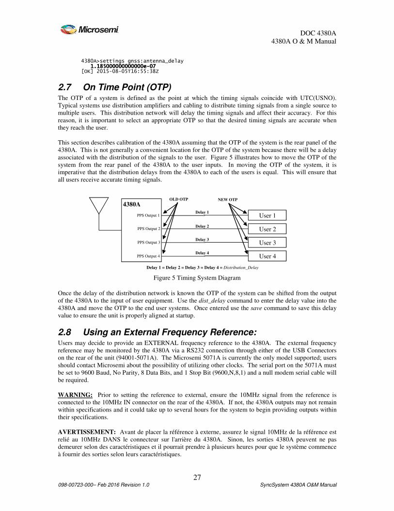
2.7 On Time Point (OTP) The OTP of a system is defined as the point at which the timing signals coincide with UTC(USNO).
Typical systems use distribution amplifiers and cabling to distribute timing signals from a single source to
multiple users. This distribution network will delay the timing signals and affect their accuracy. For this
reason, it is important to select an appropriate OTP so that the desired timing signals are accurate when
they reach the user.
This section describes calibration of the 4380A assuming that the OTP of the system is the rear panel of the
4380A. This is not generally a convenient location for the OTP of the system because there will be a delay
associated with the distribution of the signals to the user. Figure 5 illustrates how to move the OTP of the
system from the rear panel of the 4380A to the user inputs. In moving the OTP of the system, it is
imperative that the distribution delays from the 4380A to each of the users is equal. This will ensure that
all users receive accurate timing signals.
Once the delay of the distribution network is known the OTP of the system can be shifted from the output
of the 4380A to the input of user equipment. Use the dist_delay command to enter the delay value into the
4380A and move the OTP to the end user systems. Once entered use the save command to save this delay
value to ensure the unit is properly aligned at startup.
2.8 Using an External Frequency Reference: Users may decide to provide an EXTERNAL frequency reference to the 4380A. The external frequency
reference may be monitored by the 4380A via a RS232 connection through either of the USB Connectors
on the rear of the unit (94001-5071A). The Microsemi 5071A is currently the only model supported; users
should contact Microsemi about the possibility of utilizing other clocks. The serial port on the 5071A must
be set to 9600 Baud, No Parity, 8 Data Bits, and 1 Stop Bit (9600,N,8,1) and a null modem serial cable will
be required.
WARNING: Prior to setting the reference to external, ensure the 10MHz signal from the reference is
connected to the 10MHz IN connector on the rear of the 4380A. If not, the 4380A outputs may not remain
within specifications and it could take up to several hours for the system to begin providing outputs within
their specifications.
AVERTISSEMENT: Avant de placer la référence à externe, assurez le signal 10MHz de la référence est
relié au 10MHz DANS le connecteur sur l'arrière du 4380A. Sinon, les sorties 4380A peuvent ne pas
demeurer selon des caractéristiques et il pourrait prendre à plusieurs heures pour que le système commence
à fournir des sorties selon leurs caractéristiques.
4380A
User 1
User 2
User 3
Figure 5 Timing System Diagram
User 4
PPS Output 1
PPS Output 2
PPS Output 3
PPS Output 4
OLD OTP NEW OTP
Delay 1
Delay 2
Delay 3
Delay 4
Delay 1 = Delay 2 = Delay 3 = Delay 4 = Distribution_Delay

DOC 4380A
4380A O & M Manual
28 098-00723-000– Feb 2016 Revision 1.0 SyncSystem 4380A O&M Manual
Figure 6 External Frequency Reference
Current status can be determined using the status reference:frequency:external command. 4380A>status reference:frequency:external [communications] N/A [locked] true [signal] present [OK] 2015-08-05T17:17:08Z signal missing 10MHz reference signal is not present. Do NOT select the
reference type as External. cannot communicate 10MHz reference signal is present, but the system is
unable to communicate with the 5071A locked 10MHz reference signal is present and the system is able
to communicate with the 5071A not monitored 10MHz reference signal is present. The system will not
attempt to communicate with the external reference.
Note: Make sure the USB-to-Serial Converter (94001-5071A) is installed on one of the two USB ports
when the system is powered on. If not, power the system down, plug the cable in and re-apply power. The
USB/Serial Cables are programmed to communicate with an external reference (94001-5071A) or to
provide users access to the command port (94000-115200). These cables are NOT interchangeable.
To set the type of reference, use the reference_type command. If users are operating with a Microsemi
5071A and they will set the system up so the 4380A is communicating with the 5071A, select hp5071A, if
not select cesium. 4380A>reference_type hp5071a [OK] 2015-08-05T16:51:17Z
Caution: If the system is unable to communicate with the external reference and the reference_type is
hp5071A, the Alarm light will come on and the Osc Lock light will go out and remain this way after you
switch to the external reference. Make sure that you select the proper reference_type before switching to
external.
Attention: Si le système ne peut pas communiquer avec la référence externe et le reference_type est
hp5071A, la lumière d'alarme avancera et la lumière de serrure d'oscillateur s'éteindra et rester de cette
façon après toi commutez à la référence externe. Assurez-vous que vous choisissez le reference_type
approprié avant le changement à externe.
To set the reference to external, use the reference command via the command port.
4380A>reference external [OK] 2015-08-05T17:19:32Z
Note: The Alarm light will come on and the Sync light will go out for a few seconds when you switch
references. The system should clear all alarm indications within a few seconds.
To verify the settings use the settings reference command to check the current settings. 4380A>settings reference [external] [type] hp5071A[type] hp5071A[type] hp5071A[type] hp5071A [source] internal [steering] [source] gnss

DOC 4380A
4380A O & M Manual
29 098-00723-000– Feb 2016 Revision 1.0 SyncSystem 4380A O&M Manual
[timescale] [kas2] [avgfiltermax] 0 [tsepoch] 0 [tsfiltermax] 2 [tsfilterref] N/A [tsinterval] 3600 [tstimeconstant] 10800 [OK] 2015-08-05T17:22:04Z
If these settings are correct, type save to save the proper reference and reference type in the default user
configuration file on the system to ensure the system starts up properly after a reboot or power cycle.
Caution: Users should allow the external frequency reference to free run and should not manually enter
corrections/adjustments into the clock. The 4380A characterizes the clock’s frequency relative to GNSS
and manual/user adjustment of the clock frequency may cause the 4380A outputs to not meet specification
following the adjustment.
Attention: Les utilisateurs devraient permettre la référence externe de fréquence à élevé en plein air et ne
devraient pas manuellement écrire des corrections/ajustements dans l'horloge. Le 4380A caractérise la
fréquence de base à GNSS relatif et l'ajustement de manuel/utilisateur de la fréquence de base peut faire ne
pas répondre les sorties 4380A à des spécifications suivant l'ajustement.
WARNING: After replacing an external frequency reference, the restart –cold command must be
executed on the 4380A by the operator to reset the KAS2 steering algorithm. If not, the 4380A outputs
may not remain within specifications and it could take up to 9 days for the system to provide outputs within
specifications.
AVERTISSEMENT: Après remplacement d'une référence externe de fréquence, le relancement - la
commande froide doit être exécutée sur le 4380A par l'opérateur pour remettre à zéro l'algorithme de la
direction KAS2. Sinon, les sorties 4380A peuvent ne pas demeurer selon des caractéristiques et il pourrait
prendre à 9 jours pour que le système fournisse des sorties selon des caractéristiques.
2.9 Setting the System Time Manually The 4380A is capable of operating without the GNSS Receiver and maintains system time through several
methods
2.9.1 Force Time The force_time command has several options and users have the flexibility of choosing the method(s) that
will work best based on installation and system architecture. Once the command has been successfully
completed, NTP will lock to the new system time and the unit will enable the outputs.
• Default – Sets the system time to 01 Jan 2012 00:00:00
• Now – Sets the system time to the operating systems time.
• Date/Time – Allows the user to specify the date and time in the yyyy-mm-dd-hh:mm:ss format
• NTP – The system obtains the time from an NTP Server and sets the system time.
• IRIG – The system obtains the time from an IRIG Time source and sets the system time. If the
time code selected from the irig_input command does not provide the year, the user must specify
the year on the command line.
If for any reason the system is unable to successfully set the system time it will report an error.
Note: The force_time command will not work unless the steer_source is set to manual.

DOC 4380A
4380A O & M Manual
30 098-00723-000– Feb 2016 Revision 1.0 SyncSystem 4380A O&M Manual
2.9.2 External Reference When setting the time manually, it is recommended users provide a 1PPS and 10MHz. Users can select the
proper clock type for the 10MHz input using the reference_type command and then switching to reference
external when the system is properly set up. Users will need to edit the node.cfg file to use one or more
1PPS references from the 4393A Card as a steer source.
2.9.3 Disable the GNSS Tracking Alarms When using the system with manual time recovery, users can set the system up to ignore the GNSS
Tracking Alarms normally set when the system is not tracking GNSS. This can be done by setting the
timeout to ZERO. 4380A> gnss_tracking_timeout 0
To confirm the system settings, use the settings gnss:tracking_timeout command. 4380A>settings gnss:tracking_timeout 0 [OK] 2015-02-03T19:11:19Z
Caution: Setting the timeout to zero is only recommended with time sources other than GNSS. This
setting will inhibit the GNSS Tracking alarm even if the unit is using GNSS as the time source.
2.10 User Configuration Files The 4380A provides the flexibility of operating using different user configurations. Users are able to save
these configurations for system settings and ftp | real-time data logging and recall them when needed via
the command port.
2.10.1 Factory / Default User Configuration Files The 4380A will boot up with the FACTORY configuration settings automatically and will continue to use
these settings until any changes to the configuration are made and saved as the user default settings
(default). To save the user default file simply type save and press enter. This will save the updated
configuration and the 4380A will boot up (either from power on or after a reboot/restart command) using
the settings in the user default file. To see if the user settings have been saved, use the list command to
obtain a list of the possible user configuration files. If there are no user configuration files available the
system will report no files.
4380A>list 4380A>list default or no files
Note: The user default file is used at start up if it is present, otherwise the unit will start up with the factory
default file. Users are encouraged to set AND save their default system settings based on their application
so the system will start up properly when powered up or after a reboot or restart.
Users can create other configuration files. Simply make the desired changes to the system configuration,
type save and a filename to identify the configuration, and press enter. The system will save this
configuration containing the new settings. To use this configuration file, use the list command to bring up a
list of the possible configuration files, and use the load command to have the system load and start running
with the desired user configuration settings. Use the settings command to ensure the system is using the
desired settings based on the newly loaded configuration file. 4380A>save example [OK] 2015-08-05T17:22:04Z 4380A>list example default [OK] 2015-08-05T17:23:34Z

DOC 4380A
4380A O & M Manual
31 098-00723-000– Feb 2016 Revision 1.0 SyncSystem 4380A O&M Manual
4380A>load example [OK] 2015-08-05T17:24:27Z
Note: The system will recognize case sensitive alphanumeric characters, -, ‘ ‘, and _. If any other
characters are used, the system will inform the user that the filename is not valid and will not save the
settings. 4380A>save te%^$st Illegal Filename [ERROR] 2015-08-05T17:29:17Z
Users can also remove any configuration files that are no longer needed on the system. Use the list
command to bring up a list of the available configuration files and use the delete <filename> command to
remove the desired file. Users must provide the filename of the file to be removed from the system, if not
the system will provide an error message reminding the user to identify the file to be removed. 4380A>delete example OK [OK] 2015-08-05T17:19:48Z 4380A>delete FILENAME FILENAME Name of file [ERROR] 2015-08-05T17:19:59Z
Caution: Users can delete the user default file. If this is done and a new user default configuration file is
not saved, the system will use the factory defaults when rebooted, restarted, or power cycled.
Attention: Les utilisateurs peuvent supprimer le dossier de défaut d'utilisateur. Si ceci est fait et un
nouveau dossier de configuration de défaut d'utilisateur n'est pas sauvé, le système emploiera les défauts
d'usine quand rechargé, remis en marche, ou puissance fait un cycle.
2.10.2 Diff Command The 4380A will track changes to the system settings that have been made and have not been saved. Use the
diff command to provide a complete list of settings that have been modified but not saved. In the example
below the ptdavg has been changed to 20 seconds but not saved. The system will report the current setting
and the saved (original) setting in the report. 4380A>ptdavg 20 [OK] 2015-08-05T17:41:39Z 4380A>diff [current] [ptd_port] [averaging_interval] 20 [original] [ptd_port] [averaging_interval] 10 [OK] 2015-08-05T17:41:53Z
2.10.3 FTP and Real-Time (rt) Configuration Files The 4380A will boot up with the FACTORY ftp | rt log file settings automatically and will continue to use
these settings until any changes to the gnss logging functions are made and saved as the user default log
settings (default). This will save the updated logging configuration and the 4380A will use these settings
each time the system is power cycled, rebooted, or restarted. To save the default log file settings simply
type save_logs ftp or save_logs rt. To see if the user settings have been saved use the list_logs ftp or
list_logs rt command to obtain a list of the possible configuration files. If there are no user configuration
files available the system will report no files. 4380A>list_logs ftp 4380A>list_logs rt default default

DOC 4380A
4380A O & M Manual
32 098-00723-000– Feb 2016 Revision 1.0 SyncSystem 4380A O&M Manual
or if there are no log settings files, 4380A>list_logs ftp no files
Note: The ftp | rt user default files are used at start up if they are available otherwise the system will use
the factory default settings. To modify the ftp or real-time logging behavior, make the changes needed
based on your application and type save_logs ftp or save_logs rt. Users are encouraged to set the user
default ftp |rt settings based on their application so the system will properly configure the logging after a
reboot or power cycle.
Users can create other logging configuration files. Simply make the desired changes to the logging
configuration, type save_logs ftp or save_logs rt and a filename to identify the configuration and press
enter. The system will save this configuration containing the new settings. To use this log configuration
use the list_logs ftp or list_logs rt command to bring up a list of the possible configuration files and use the
load_logs ftp or load_logs rt command to have the system load and start running with the desired
configuration settings. Use the settings command to ensure the system is using the desired settings based
on the newly loaded logging configuration file. 4380A>save_logs ftp example [OK] 2010-05-25T17:32:27Z 4380A>list_logs ftp (working) example default [OK] 2015-08-05T18:31:43Z 4380A>load_logs ftp example [OK] 2015-08-05T18:31:43Z
Note: The system will recognize case sensitive alphanumeric characters, -, ‘ ‘, and _. If any other
characters are used the system will inform the user that the filename is not valid and will not save the
settings. 4380A>save_logs rt te%^$st Illegal filename [OK] 2015-08-05T20:52:41Z
The log files contain a header at the start of each line proceeded by a # indicating the data type for that line
of data. If the user is logging multiple data types it allows them to sort out the data fields.
FTP: #RANGEA,COM1_5,0,58.5,FINE,1518,243060.000,00a00008,5103,3311;20 … #RXHWLEVELSA,COM1_5,0,58.5,FINE,1518,243060.000,00a00008, … #WAAS9A,COM1_5,0,54.5,SATTIME,1518,243239.000,00a00008 …
Real-Time:
$GPGGA,200240.00,3827.9772032,N,07726.4522017,W,9,08,1.5,51.663,M,,,03,0138*14 $GPGGA,200241.00,3827.9771961,N,07726.4521871,W,9,08,1.5,51.692,M,,,03,0138*1C $GPGGA,200242.00,3827.9771900,N,07726.4521733,W,9,08,1.5,51.703,M,,,04,0138*1F
Users can also remove any logging configuration files that are no longer needed on the system. Use the
list_log ftp|rt command to bring up a list of the available configuration files and use the delete_logs ftp|rt
<filename> command to remove the desired file. Users must provide the filename of the file to be
removed from the system, if not the system will provide an error message reminding the user to identify the
file to be removed. 4380A>delete_logs ftp example OK [OK] 2010-05-25T17:33:43Z

DOC 4380A
4380A O & M Manual
33 098-00723-000– Feb 2016 Revision 1.0 SyncSystem 4380A O&M Manual
4380A>delete_logs ftp <ftp | rt> FILENAME FILENAME Name of file [ERROR] 2015-08-05T20:55:19Z
Caution: Users can delete the default file(s). If this is done and a new user default logging configuration
is not saved, the system will use the factory defaults when rebooted, restarted or power cycled.
Attention: Les utilisateurs peuvent supprimer les dossiers de défaut. Si ceci est fait et une configuration
de notation de nouveau défaut d'utilisateur n'est pas sauvée, le système emploiera les défauts d'usine quand
rechargé, remis en marche ou puissance fait un cycle.
Use the settings gnss_logging:ftp or gnss_logging:rt command to ensure the system is using the desired
settings based on the newly loaded configuration file. Use the save command to save the current system
settings and this will also save the log settings and the system will use these settings after a power cycle,
restart, or reboot.
2.10.4 System Configuration Files (Syscfg) The system is capable of allowing users to monitor and verify system configurations using the syscfg
command. The files can be set up so critical system parameters can be checked against user defined
nominal values and when the system settings do not match the nominal values the system provides a user
defined alarm string to describe the configuration mismatch. This applies to any data set the system
generates on Port 1900. Users can define the field and the nominal value. Users are cautioned that these
values reported on Port 1900 are checked and must exactly match the value in the syscfg file. As an
example, if you are operating in the dynamic positioning mode you would not want to set a nominal value
for the altitude, latitude or longitude. You can however set the nominal value to “dynamic” for the
positioning mode to alert you if someone places the unit in the incorrect positioning mode.
By default the system is operating in the “Standalone” mode and in this mode these parameters are not
checked against the information provided on Port 1900. To enable this feature users will need to set the
nominal values in the /mod/tsc/syslog/localcfg.py file. If no user specific parameters are set the system will
use the factory default file /usr/tsc/syscfg/syscfg_default.py. Once the settings are entered users can turn
this feature on using the syscfg command. See Appendix D for examples. 4380A>syscfg --mode system Set Mode [OK] 2013-09-05T23:53:17Z
Users can export the file using the --export option, download it via FTP, and edit the file in an editor of
their choice. A Linux editor is recommended to prevent the Carriage Returns/Linefeeds from becoming
and issue. Once the file has been edited users can upload the new file and then use the --import option to
bring in the new file. Once successfully imported the system will load and begin using the imported file.
See Appendix D for the detailed command information.
To check the status of this feature use the settings syscfg command. 4380A>settings syscfg [mode] system [OK] 2013-09-05T23:51:48Z
If configuration errors are detected the system will light the front panel alarm light and the alarms
command will provide an indication of the error. 4380A>alarm [alarm] syscfg -- Incorrect format in slot 6 port 2: expected=B, actual=H [OK] 2013-09-05T23:54:07Z 4380A>alarms [syscfg]

DOC 4380A
4380A O & M Manual
34 098-00723-000– Feb 2016 Revision 1.0 SyncSystem 4380A O&M Manual
[occurrences] 1 [set] [what] Incorrect format in slot 6 port 2: expected=B, actual=H [when] 2013-09-05-23:53:16.800 [OK] 2013-09-05T23:55:35Z
To get a complete list of the configuration errors use the status syscfg:errors command. 4380A>status syscfg:errors [1] Incorrect format in slot 6 port 2: expected=B, actual=H [2] Incorrect signal word in slot 6 port 2: expected=120, actual=121 [OK] 2013-09-05T23:56:38Z
To stop using this feature use: 4380A>syscfg --mode standalone Set Mode [OK] 2013-09-05T23:53:17Z
Once the system has been set up for the correct mode use the save command to save the current system
settings and the system will use these settings after a power cycle, restart, or reboot.
2.11 Powering the System Off To remove power from the 4380A remove the input power sources from Power Supply #1 and #2.

DOC 4380A
4380A O & M Manual
35 098-00723-000– Feb 2016 Revision 1.0 SyncSystem 4380A O&M Manual
3. Operations Two distinct tasks are performed by the 4380A 1) collection of GNSS measurement data 2) the generation
of timing signals. These two tasks are entirely separate except for the fact that they must share CPU time
and data from the GNSS receiver. Because the generation of timing signals requires that events (e.g., clock
steering) occur at very specific times, operational precedence is always given to timing tasks. As a result,
any operations concerning the collection and storage of GNSS data are postponed until all timing
operations have been completed.
3.1 Front Panel The 4380A has several front panel indicators to provide the operator with the overall status of the unit as
well as a visual alarm indication if a problem with the hardware or the unit detects a condition that would
cause the output signals to be outside of their timing specifications. More detailed status information can
be retrieved using the status command on the Command Port.
Figure 7 4380A Front Panel
3.1.1 Power Supply Indicators Each power supply has a front panel indicator that provides the operator an instant visual indication of the
supply status. Power Supply #1 is on the left, power supply #2 is on the right as viewed from the front.
Indicator Status
Off No power is being provided to the 4380A.
Green Power supply is good and is supplying power.
Red 4380A has power to the other module and this module has failed, is not seated properly,
or is unplugged from it’s power source.
Table 1 Power Supply Indicator Status
3.1.2 Alarm Indicator The Alarm LED will turn red when the unit is not producing timing within their specifications or the
system has suffered a major hardware failure.
Indicator Status
Off Unit has no current alarms.
Green This indicator should only turn green during the front panel POST.
Red – Flashing
½ second
This indicator reflects the unit has a non-critical alarm
Failed validation/self test.
Red This indicator reflects the unit has a critical alarm
Table 2 Alarm Indicator
3.1.3 SYNC Indicator The SYNC indicator on the 4380A shall indicate the current status of the internal, external, steer source, or
timescale references. Indications shall be based on the reference type currently in use as specified by the
operator.
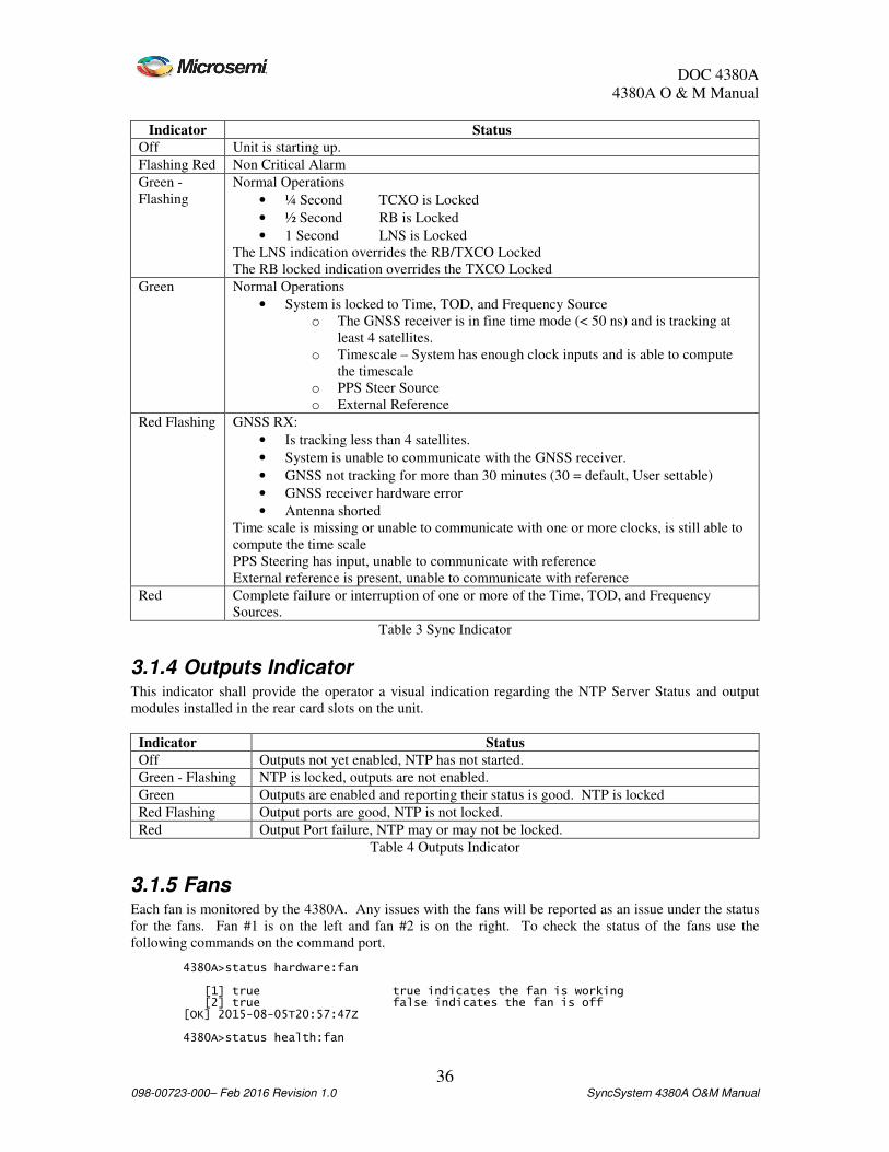
DOC 4380A
4380A O & M Manual
36 098-00723-000– Feb 2016 Revision 1.0 SyncSystem 4380A O&M Manual
Indicator Status
Off Unit is starting up.
Flashing Red Non Critical Alarm
Green -
Flashing
Normal Operations
• ¼ Second TCXO is Locked
• ½ Second RB is Locked
• 1 Second LNS is Locked
The LNS indication overrides the RB/TXCO Locked
The RB locked indication overrides the TXCO Locked
Green Normal Operations
• System is locked to Time, TOD, and Frequency Source
o The GNSS receiver is in fine time mode (< 50 ns) and is tracking at
least 4 satellites.
o Timescale – System has enough clock inputs and is able to compute
the timescale
o PPS Steer Source
o External Reference
Red Flashing GNSS RX:
• Is tracking less than 4 satellites.
• System is unable to communicate with the GNSS receiver.
• GNSS not tracking for more than 30 minutes (30 = default, User settable)
• GNSS receiver hardware error
• Antenna shorted
Time scale is missing or unable to communicate with one or more clocks, is still able to
compute the time scale
PPS Steering has input, unable to communicate with reference
External reference is present, unable to communicate with reference
Red Complete failure or interruption of one or more of the Time, TOD, and Frequency
Sources.
Table 3 Sync Indicator
3.1.4 Outputs Indicator This indicator shall provide the operator a visual indication regarding the NTP Server Status and output
modules installed in the rear card slots on the unit.
Indicator Status
Off Outputs not yet enabled, NTP has not started.
Green - Flashing NTP is locked, outputs are not enabled.
Green Outputs are enabled and reporting their status is good. NTP is locked
Red Flashing Output ports are good, NTP is not locked.
Red Output Port failure, NTP may or may not be locked.
Table 4 Outputs Indicator
3.1.5 Fans Each fan is monitored by the 4380A. Any issues with the fans will be reported as an issue under the status
for the fans. Fan #1 is on the left and fan #2 is on the right. To check the status of the fans use the
following commands on the command port. 4380A>status hardware:fan [1] true true indicates the fan is working [2] true false indicates the fan is off [OK] 2015-08-05T20:57:47Z 4380A>status health:fan
DOC 4380A
4380A O & M Manual
37 098-00723-000– Feb 2016 Revision 1.0 SyncSystem 4380A O&M Manual
[1] [active] false [occurrences] 0 [2] [active] false [occurrences] 0 [OK] 2015-08-05T20:58:17Z
The active line will display false when the fans are functioning normally and true for one or both fans if
they are not. If a fan is having issues you will see the number of occurrences increment up from 0 as each
event occurs.
3.1.6 Status Pushbutton When pressed, this button will display the 4380A’s current IP Address if the address has been by a DHCP
Server or statically. If the system is set up to use DHCP and it was unable to obtain an IP Address the
system will set the IP Address to 0.0.0.0 and will not display an IP Address when this button is pressed.
After displaying the IP address (if set) the unit will display the system status screen.
The third feature of this button is enabled by default. If this button is pressed for ~10 seconds it will set the
IP Address on the system to 192.168.0.1. This is a temporary setting and it will not survive a system reboot
or power cycle and may even reset if the LAN cable is pulled from the rear panel. This feature can be
disabled using the frontpanel_button command and setting the value to 0. Once set the value can be
confirmed using the settings hardware command. Make sure to save the system settings. 4380A>frontpanel_button 0 OK 4380A>settings hardware [enable_fp_button] false[enable_fp_button] false[enable_fp_button] false[enable_fp_button] false
3.2 Rear Panel All hardware interfaces and connectors are located on the rear panel of the 4380A. The system can provide
eight types of output timing signals: 1 PPS, 10 MHz, 5MHz, 1MHz, DC IRIG, AM IRIG, NASA36, and
the downstream 4380A reference signals depending on which output modules are installed and the system
configuration settings. Each output module has four connectors. These outputs can be used to directly feed
other instruments or feed a distribution system that provides any number of user outputs. The on-time-
point (OTP) of the system is typically at the output of the BNC connectors (Section 2.6) but it can be
adjusted to be any point in an integrated system by accounting for distribution delays and adjusting the
antenna delay value (Section 2.7).
Figure 8 4380A Rear Panel
Under normal operations the only inputs required for operation of the 4380A are at least one power source
and a GNSS Antenna. GNSS is the source of time (UTC) for the unit and the 4380A will not start up
normally without it. Once at least four satellites have been acquired the unit will continue to output timing
signals even when the GNSS antenna is removed. However, the accuracy of these outputs will degrade
over time.
Connection to a local area network (LAN) is supported by the 4380A. This allows users to access the unit
remotely and also provides error monitoring capabilities. In addition, the 4380A can serve as the source of
network time for other systems on the network if using network time protocol (NTP). The system can only

DOC 4380A
4380A O & M Manual
38 098-00723-000– Feb 2016 Revision 1.0 SyncSystem 4380A O&M Manual
support ~100 NTP users. The USB ports can be used in conjunction with a USB-to-Serial conversion cable
to allow users access to the command port via a local terminal and/or allows the system to communicate
with an external reference (5071A). The GNSS Antenna connector is used to connect the GNSS Antenna
to the system. The 10MHz IN connector is used to provide the 10MHz signal input from an external
frequency reference. See Figure 9.
Figure 9 4380A Rear Panel Connections
3.3 Software
3.3.1 Current Version 4380A: Users can obtain the current software version via the command port using the status unit:ver
command. 4380A>status unit:ver Sync SystemSync SystemSync SystemSync System----1111----0000----0000 [OK] 2015-08-05T21:06:30Z
CAUTION: Do NOT remove the software flash while the unit is on, it may cause an unrecoverable error
on the flash rendering the system inoperative.
GNSS Receiver: Users can obtain the current GNSS firmware version by sending the status gnss:model
command. 4380A>status gnss:model [hw_version] OEMV3G-4.01-X2T [name] L12LV [serial_number] DAB08410131 [sw_version] 3.803 [OK] 2015-08-05T21:07:04Z
3.3.2 Software Updates Upgrading the software can be accomplished via two methods.
3.3.2.1 Flash Card Replacement This requires removing the currently installed flash disk and installing a new one which has the updated
software. Power the system down, pull the unit from the rack and remove the top cover. Press and release
the SD card located in the SD Card slot , remove the current flash disk, and replace it with the new flash.
Once the new flash is securely installed install the opt cover, install the unit in the rack, and power the
system up.
DOC 4380A
4380A O & M Manual
39 098-00723-000– Feb 2016 Revision 1.0 SyncSystem 4380A O&M Manual
Caution: The system network and user configuration settings are NOT saved and the system will need to
be set up.
Attention: Les arrangements de configuration de réseau et d'utilisateur de système ne sont pas sauvés et le
système devra être établi.
3.3.2.2 Remote Software Update The 4380A software can be updated remotely over the network. Users can download the new software
image onto the flash and run the software_update command to load the new software onto the flash. Once
the software has successfully been updated the system will automatically reboot. The system network and
user configuration files will be saved and reloaded onto the new software image and you will not need to
set the system up. To update the system with the new software:
1. FTP into the 4380A and log in (username: update, password: update).
2. Switch to binary transfer mode if needed, upload (put) the .iso file, and quit ftp.
localhost> ftp 192.168.1.254 Connected to 192.168.1.254. 220 Sync System FTP server (Version 6.00LS) ready. Name (192.168.1.254:localhost): update 331 Guest login ok, send your email address as password. Password: update 230 Guest login ok, access restrictions apply. Remote system type is UNIX. Using binary mode to transfer files. ftp> binary Use this command to switch to binary if needed. 200 Type set to I. ftp> put Sync System.Sync System-1-0-1.iso local: Sync System.Sync System-1-0-1.iso remote: Sync System.Sync System-1-0-1.iso 229 Entering Extended Passive Mode (|||53133|) 150 Opening BINARY mode data connection for 'Sync System.Sync System-1-0-1.iso'. 100% |*****************************************************************************| 9644 KB 397.51 KB/s 00:00 ETA 226 Transfer complete (unique file name:Sync System.Sync System-1-0-1.iso). 10856448 bytes sent in 35.75Seconds 303.68Kbytes/sec. ftp> quit 221 Goodbye.
3. Use the software_update <filename> command to update the software. When the application
launches, users should see the following information on the console as the updater application
run through the routine to update the system software. 4380A>software_update Sync System-1-0-1.iso common_updater.sh: Invoked with command line: /updates/Sync System-1-0-1.iso --noreboot common_updater.sh: Extracting new updater from /updates/src/cpio-image.gz common_updater.sh: New updater extracted, launching it now. common_updater.sh: Invoked with command line: /updates/Sync System-1-0-1.iso --noreboot --stage2 common_updater.sh: Stage 2 updater running common_updater.sh: System is currently running from /dev/mmcsd0s1; applying updates to /dev/mmcsd0s2 common_updater.sh: Creating filesystem on /dev/mmcsd0s2a ..... ..... . done. common_updater.sh: Creating filesystem on /dev/mmcsd0s2e ..... ..... . done. common_updater.sh: Invoking product-specific pre-extract function common_updater.sh: Preserving current syslog common_updater.sh: Capturing data to be preserved across the update common_updater.sh: Storing files ..... .... done. common_updater.sh: Extracting updates from image file /updates/src/cpio-image.gz common_updater.sh: Unpacking files ..... ..... ..... ..... ..... ..... ..... ..... ..... ..... ..... ..... ..... done. common_updater.sh: Restoring overlay data to be preserved across the update common_updater.sh: Unpacking files ..... .... done. common_updater.sh: Editing new /etc/fstab to change /dev/mmcsd0s1 to /dev/mmcsd0s2 common_updater.sh: Invoking product-specific post-extract function Sending command words: 0x03a50301 0x00000000 common_updater.sh: FPGA warmstart register has been cleared; a coldstart will occur common_updater.sh: Cleaning up temporary files and flushing all data to disk common_updater.sh: Setting bootable flag in partition 2
DOC 4380A
4380A O & M Manual
40 098-00723-000– Feb 2016 Revision 1.0 SyncSystem 4380A O&M Manual
common_updater.sh: UPDATE SUCCESSFUL Outputs disabled Warm start successfully disabled Rebooting... [OK] 2015-08-05T15:17:53Z
4. Once the update is complete the system will automatically reboot. Local users will see the
front panel display lock up for ~2 minutes. After this the system will begin launching the
application and local users will see the typical boot process. The application start up will take
~2 minutes. Once the SYNC light is on it will take an additional 1.5 to 2 minutes for NTP to
lock and for the outputs to be enabled.
Note: Users can obtain the new software image and software release notes from Microsemi
http://ftd.microsemi.com/time >Products > Time & Frequency Distribution > GPS Instruments >
SyncSysmte 4380A > Documents . Refer to the Software Release Notes for specific instructions related to
a particular revision of software.
Caution: If the software update is not applied and the unit is power cycled users will need to upload the
.iso file again in order to update the system software. The .iso file will be wiped from the system since it is
held in volatile memory.
Attention: Si la mise à jour de logiciel n'est pas appliquée et l'unité est les utilisateurs faits un cycle par
puissance devra télécharger le dossier de .iso encore afin de mettre à jour le logiciel système. Le dossier de
.iso sera essuyé du système puisqu'on le tient dans la mémoire volatile.
3.3.3 GNSS Firmware Updates Updating the firmware on the GNSS receiver requires that the GNSS receiver be removed from the system,
updated, and reinstalled. The GNSS Firmware version can be checked using the status gnss:model
command. 4380A>status gnss:model [hw_version] OEMV3G-4.01-X2T [name] L12LV [serial_number] DAB08410131 [sw_version] 3.803[sw_version] 3.803[sw_version] 3.803[sw_version] 3.803 [OK] 2015-08-05T21:07:04Z
3.4 User Interfaces Software interfaces on the 4380A are limited in their ability to provide users with real-time control.
Adjusting some system parameters during operation of the 4380A can seriously impact the timing
performance of the unit and therefore the ability to adjust these parameters is limited by the software. Once
properly installed, the 4380A serves as a stand-alone device which requires little to no interaction. Remote
error monitoring capabilities are provided as a means to ensure that the unit is powered and operating
properly.
3.4.1 Telnet One advantage of accessing the 4380A via telnet is that multiple telnet sessions may be active at once. It is
recommended that users connect directly to the desired port based on the function(s) they are going to
perform.
• 1135 Real Time Logging
• 1700 Command
• 1800 Diagnostics
• 1900 Status
• 2100 Average TIC Data (4393A Card)

DOC 4380A
4380A O & M Manual
41 098-00723-000– Feb 2016 Revision 1.0 SyncSystem 4380A O&M Manual
• 2101 Raw TIC Data (4393A Card)
3.4.1.1 Real Time Data Port (1135) Certain applications require that GNSS data be retrieved in a timely manner. For this purpose, Port 1135
may be configured to provide real-time data output. Users can specify which logs are output and users may
request any of the ASCII logs specified in the user manual for the Novatel OEM6 receiver
(http://www.novatel.com/support/info/documents/). See the log command.
3.4.1.2 Command Port (1700) System commands can be issued to the 4380A via the command port. These commands provide a limited
set of operations to be used for remote control of the system. Typically, a remote monitoring station may
record an error that indicates user intervention is required. The remote monitoring station would then be
able to access the command port via the Ethernet and issue the commands required for recovering from the
error. The following list provides a short description of each command.
Note: All commands are in lowercase and the commands are case sensitive.
Command Description
Basic Commands
help, h or ? <command> Display help for a command or list all commands. Proper format is to
proceed the command with help, h, or ? help <command>
quit Closes the command connection and terminates the telnet connection.
Status Commands
show Shows the current system factory (config), user configuration (settings),
network (network), and system status (status) values. This command is
the equivalent of sending these 4 commands at the same time.
status Shows the values of all runtime status variables
alarm Shows the current alarm state
alarms Shows active alarms
config Shows unit configuration parameters
network Show network interface configuration. Note: These settings do not
apply if the mode=DHCP.
syslog Dump the system log file.
diag Adjust diagnostic logging levels.
diag_port Switch to the diagnostic port (1800).
ptdavg_port Switches the command port display to port 2100 to view the average
measurement results.
ptdraw_port Switches the command port display to port 2101 to view the raw
measurements every second.
status_port Switch to the status port (1900)
Settings
settings Shows the current user control/configuration settings.
diff Displays any difference between the current system settings and the
saved user configuration file.
load Restore system configuration settings from a file on the disk
save Save current configuration settings to disk. save <filename>. Default =
<default>
list List available user configuration files available on disk. If there are no
files listed the 4380A is using the factory default settings.
delete Deletes specified user system configuration files.
Manual Time Setting
Commands

DOC 4380A
4380A O & M Manual
42 098-00723-000– Feb 2016 Revision 1.0 SyncSystem 4380A O&M Manual
force time Manually set the time and enable outputs when GNSS is not available
adjust_time Manually adjust the time in 1 second increments when in manual time
mode
adjust_pps Manually adjust the sub-second time of the system when in manual time
mode.
steer_frequency Manually change the frequency of the instrument's outputs.
steer_phase Manually change the phase of the instrument's outputs
GNSS Commands
latitude Sets latitude, Default [N], option [S] or [-].
longitude Set longitude. longitude <degrees> [E](default) or [W]
altitude Set Antenna altitude Default units = [m]meters, optional [ft] feet
fix_position Sets a static location based on current GNSS determined position
location or it allows the operator to enter the latitude, longitude, and
altitude. [current] or [<latitude> <longitude> <altitude>]. Default =
Current.
position_period Set GNSS auto-positioning period. position_period <period>
[h]ours(default) or [m]inutes.
position_mode Set GNSS position mode. position_mode [auto|manual|dynamic]
antenna_delay Sets GNSS antenna delay in seconds.
antenna_voltage Set GNSS antenna voltage (0,5,12)
mask_angle Set mask angle. mask_angle <degrees>
datum Set GNSS datum, Default = wgs84, option nad83
gnss_tracking_timeout Set GNSS tracking lost timeout in seconds.
Logging Commands
log_interval Sets the GNSS logging interval for ftp files, in minutes log_interval
<interval in minutes> [1-1400]
log_number Sets the maximum number of GNSS ftp log files. log_files <number>
log_compression Enable or disable GZIP compression for the ftp log files. 0=Off 1=On
log_filename Set name pattern of log files log_filename <user|timestamp>
Timestamp – files are named based on the date/time they were created
with an optional suffix. User – Users supplies file prefix name, Unique
ID, and suffix for the filename.
log (ftp|rt) [type]. Add a GNSS log. User must specify if the log is for ftp or real time (rt)
logs, and the log type desired from the Novatel receiver.
unlog (ftp | rt) [type] Clear specified GNSS logs. unlog (rt|ftp) [type]
Default = all logs.
log_enable (ftp|rt) Enable or disable GNSS logging, Specify ftp or real time (rt) then off|on.
0=Off, 1=On
list_logs (ftp|rt). Lists the user gnss logging settings for the ftp or real-time (rt)
configuration files. If there are no files listed the 4380A is using the
factory default settings.
save_logs (ftp|rt). Save GNSS logging settings to disk. logs_save (rt|ftp) <filename>.
Default = <default>.
load_logs (ftp|rt). Restore the ftp or rt user logging configuration settings from file(s) on
the disk
delete_logs (ftp|rt) Deletes specified user ftp|rt logging configuration files.
Reference Commands
reference Indicates which frequency reference to use (internal | external |
timescale)
reference_type Indicates which frequency reference is providing the external reference
input (cesium | hp5071a | maser)
steer_source Sets the phase measurement source (gnss | manual)
DOC 4380A
4380A O & M Manual
43 098-00723-000– Feb 2016 Revision 1.0 SyncSystem 4380A O&M Manual
Hardware Output Commands
irig Allows the operator to set the IRIG codes on the 4394A (DC IRIG) and
4387A (AM IRIG) Cards.
irig_input Allows the operator to set the IRIG input codes on the 4383A IRIG
input Card.
jam_sync Synchronizes the system 1 PPS to the reference input.
pps Allows the operator to set the PPS parameters on the 4394A and 4394A-
ECL Cards.
nasa36 Allows the operator to enable the Nasa36 time code on the selected
4387A (AM IRIG) card port.
Clock Commands
add_clock Add a clock to the timescale
config_clock Change settings of a timescale clock
edit_clock Change the kas2 settings of a timescale clock
remove_clock Remove a clock from the timescale
System Commands
clear_alarms Clears latched alarm events.
firewall Configures system firewall.
frontpanel_button Enables(1) or disables (0) the front panel button from resetting the units
IP address if held in for ~10Seconds.
hostname Allows user to change domain / hostnames.
network_config Set up network settings. [--mode DHCP|static] [--ip <ip>] [--mask
<netmask>] [--broadcast <broadcast>] [--gateway <gateway>]
prompt Allows the operator to change the command prompt for the current
session or make the changes part of the system default settings.
ptdavg Allows the user to set the averaging interval (in seconds) for the TIC
cards installed in the unit. Valid intervals are 1, 10, 20, 60 and 300
seconds.
reboot Reboots the 4380A
restart Restarts the application without rebooting the system
software_update Execute the software update routine.
syscfg System Configuration commands
Other Commands
avgfiltermax Change the average filter max
remote_ntp_offset Returns the offset in seconds between Sync System time and that of an
external NTP server
Table 5 System Command List
Access to the 4380A command port is available via telnet (Port 1700) and through the USB Ports located
on the back of the unit via the 94000-115200 Console Cable. The 4380A is a DTE device utilizing the
RS232 communication protocol. Settings for the port are 115,200 baud, 8 data bits, 1 stop bit, no parity,
and no flow control. It is sometimes necessary to access the system via the USB port because the 4380A
may not be accessible via the network until the IP Address has been set.
3.4.1.3 Diagnostic Port (1800) The 4380A provides an IP port to aid in diagnosing system errors. Each of the subsystems within the
4380A provides diagnostic output that can aid in identifying system errors. It is typically not necessary for
users to access the diagnostic port because all system errors are reported on the front panel (Alarm Light),
in the alarms list (status alarm) and/or can be recovered using the syslog command.
Diagnostic messages are only displayed on the diagnostic port. If users wish to save the messages provided
by the diagnostic port then the output of this port must be saved to a file. It is recommended that diagnostic

DOC 4380A
4380A O & M Manual
44 098-00723-000– Feb 2016 Revision 1.0 SyncSystem 4380A O&M Manual
messages be saved only to remote systems and not locally on the 4380A. Storing files locally may cause
the file system to exceed its storage capacity and the 4380A will no longer operate.
The options for the diagnostic outputs include error, info, or debug messages from the sub-systems listed
below. To determine the current settings telnet into the command port and use the settings diaglog
command. 4380A>settings diaglog [clock] info [cpld4370] info [gnss] info [kas2] info [lnsrawstate] info [software] info [timecode] info [tsc4370] info [tsgather] info [warmstart] info [OK] 2015-08-07T20:35:22Z
To change the settings use the diag command then specify which subsystem you would like to change
(gnss, kas2, clock, tagnss, timecode, tsc4370), then specify which message types (error, info, or debug) you
would like to see for that subsystem. Example – if you want to look at the debug messages for the GNSS
use the diag gnss debug command. You can verify this by using the settings diaglog command. 4380A>diag gnss debug [OK] 2015-08-07T20:36:07Z 4380A>settings diaglog [clock] info [cpld4370] info [[[[gnssgnssgnssgnss] debug] debug] debug] debug [kas2] info [lnsrawstate] info [software] info [timecode] info [tsc4370] info [tsgather] info [warmstart] info [OK] 2015-08-07T20:36:24Z
Users can modify these settings as needed and are able to save these settings to the default start up if
desired by typing save. These settings can also be saved to a different configuration file if desired by
typing save and providing a configuration filename.
3.4.1.4 Status Port (1900) This port provides users with real time system status updates. As the fields that are displayed using the
config, settings, status, and network commands are updated internally they are forwarded to this port in real
time. Users wanting to display system parameters, measurements, and/or alarms in real time are able to use
the data provided by the status port to update their displays in real time. See Appendix C for an example of
the data provided by the status port.
3.4.1.5 Average TIC Data Port (2100) This port provides users with average measurement results from each of the 4393A TIC Cards installed in
the 4380A. The measurements will only be available for the port(s) on the card(s) that detect a 1PPS input.
The measurements will automatically be output once the averaging is complete based on the settings
ptd_port value. Ch0 - Ch41 (20 event average): 7.964 ns 1276616379 S 594583 uS; sd: 0.053169 ns Ch0 - Ch42 (20 event average): 8.444 ns 1276616379 S 596166 uS; sd: 0.045333 ns Ch0 - Ch43 (20 event average): 15.995 ns 1276616379 S 597470 uS; sd: 0.053169 ns Ch0 - Ch44 (20 event average): 15.695 ns 1276616379 S 598818 uS; sd: 0.035163 ns Ch0 - Ch41 (20 event average): 7.938 ns 1276616399 S 594336 uS; sd: 0.042749 ns

DOC 4380A
4380A O & M Manual
45 098-00723-000– Feb 2016 Revision 1.0 SyncSystem 4380A O&M Manual
Ch0 - Ch42 (20 event average): 8.418 ns 1276616399 S 595947 uS; sd: 0.052346 ns Ch0 - Ch43 (20 event average): 15.995 ns 1276616399 S 597289 uS; sd: 0.053169 ns Ch0 - Ch44 (20 event average): 15.712 ns 1276616399 S 598651 uS; sd: 0.067684 ns
The data fields are described below:
• Ch0: 4380A internal 1PPS
• ChXY: X = Slot #, Y = Port #.
• (NN event averaging): Number of averages used to compute the results.
Note: Typically the value of the settings ptd_port. This value may be different for a set of
measurements once the outputs are enabled, the user changes the averaging value, or the port is
connected or disconnected during the measurement period.
• NN.NNN ns: Measurement results.
• XXXXXXXXXX S: The second (from 1 Jan 1970) when the average was computed.
• NNNNNNN uS: The fractional second the average was computed. This value plus the number of
seconds provides the time stamp when the average was computed.
• sd: X.XXXXXX ns: Standard deviation of the measurement.
3.4.1.6 Raw TIC Data Port (2101) This port provides users with raw measurement results from each of the 4393A TIC Cards installed in the
4380A. The measurements will only be available for the port(s) on the card(s) that detect a 1PPS input.
The measurements will automatically be output once per second. Ch0 - Ch43 (1 event average): 16.042 ns 1276616720 S 134860 uS; sd: 0.000000 ns Ch0 - Ch44 (1 event average): 15.698 ns 1276616720 S 171247 uS; sd: 0.000000 ns Ch0 - Ch41 (1 event average): 7.917 ns 1276616720 S 234528 uS; sd: 0.000000 ns Ch0 - Ch42 (1 event average): 8.469 ns 1276616720 S 272801 uS; sd: 0.000000 ns Ch0 - Ch41 (1 event average): 7.917 ns 1276616721 S 131575 uS; sd: 0.000000 ns Ch0 - Ch42 (1 event average): 8.367 ns 1276616721 S 147795 uS; sd: 0.000000 ns Ch0 - Ch43 (1 event average): 16.042 ns 1276616721 S 161232 uS; sd: 0.000000 ns Ch0 - Ch44 (1 event average): 15.698 ns 1276616721 S 193148 uS; sd: 0.000000 ns
The data fields are described below:
• Ch0: 4380A internal 1PPS
• ChXY: X = Slot #, Y = Port #.
• (NN event averaging): Should always display 1 event average.
• NN.NNN ns: Measurement results.
• XXXXXXXXXX S: The second (from 1 Jan 1970) when the average was computed.
• NNNNNNN uS: The fractional second the average was computed. This value plus the number of
seconds provides the time stamp when the average was computed.
• sd: 0.00000 ns: Standard deviation should always be ZERO.
3.4.2 File Transfer Protocol (FTP) Allows users to:
• Obtain the FTP log files and the RINEX files. The gnss log files are available in the ftp user’s
home directory and the rinex files are available in the rinex subdirectory. User name and
password = ftp. The ftp user has read and write access for the GNSS log files and the ftp user can
delete the GNSS log files as needed. The ftp user can get to the RINEX files using the change
directory command (cd rinex) and has read permissions but is unable delete the files in the rinex
subdirectory.
• Upload a new software version (.iso) and use the software_update command to update the system
software. User name and password = update.
• Manage the systems mibs files (SNMP)

DOC 4380A
4380A O & M Manual
46 098-00723-000– Feb 2016 Revision 1.0 SyncSystem 4380A O&M Manual
3.4.3 Network Time Protocol (NTP) Network Time Protocol (NTP) is provided for the dissemination of time to other devices on the network.
The NTP structure classifies devices based upon levels referred to as stratums. Stratum-1 indicates a clock
that is obtaining time from a reference clock. The 4380A NTP server is a stratum 1 server. To check the
status of the internal NTP Server telnet into port 1700 and use the status reference:ntp command. locked =
true indicates the system is providing accurate time, false indicates it is not. The source should indicate that
it is using the internal reference clock. The 4380A is capable of supporting ~100 NTP Clients. 4380A>status reference:ntp [locked] true [source] internal refclock [OK] 2015-08-07T20:38:40Z
3.4.4 Simple Network Management Protocol (SNMP) The 4380A includes an SNMP agent to provide external monitoring of system status via a Network
Management System (NMS) . The agent provides the ability to get status but does not provide SNMP trap
or set capability. SNMP is a protocol used by devices to share system information with a SNMP NMS
responsible for monitoring the status of multiple devices. When polled by the NMS the 4380A retrieves the
desired system information and provides it to the NMS.
The system supports SNMP Version 3 and the community string (-c) is tsc.
The Management Information Base (MIB) files describe the structure of the management data of a device
subsystem and are stored on the 4380A in the MIBS subdirectory of the FTP directory. They can be
retrieved from the unit via a FTP client (username: ftp, password: ftp)
3.5 Status Command The 4380A provides overall system status, health, and measurement results via the status command
available on the command port (1700). For more detailed information and a description of the fields refer
to Appendix B.
Status provides a sequence of field names to distinguish various devices and information from one another.
Each information field has a unique ID. Users can display the entire set of data fields using the status
command. It is possible to further refine the data requested by adding additional information fields to the
command line. For example, if the user simply wanted to get the information on this system type status
unit. 4380A>status unit [network] [MAC] 00:30:96:00:01:02 [broadcast] 192.168.0.255 [default_gateway] 192.168.0.1 [ip] 192.168.0.60 [netmask] 255.255.255.0 [serial_number] SP00265 [start] 2015-08-05-14:21 [uptime] 2 days, 6 hours, 18 minutes [ver] Sync System-5-1-0 [OK] 2015-08-07T20:40:45Z
Users can further refine the requested data fields by adding the desired information line to the field to look
for specific data. If the user wanted to look for the system uptime, the user would simply add a “:” then the
sub-category under unit. Additional subcategories can be added to the command line, separated with the
“:”. 4380A>status unit::::uptime 3 days, 4 hours, 42 minutes [OK] 2015-08-07T20:41:43Z

DOC 4380A
4380A O & M Manual
47 098-00723-000– Feb 2016 Revision 1.0 SyncSystem 4380A O&M Manual
4380A>status health:fan:1 [active] false [occurrences] 0 [OK] 2015-08-07T20:41:57Z
3.6 GNSS Data Logging Certain applications require that GNSS data be retrieved in a timely manner. There are two available
options for this purpose.
• FTP Data Logging
• Real Time Data
3.6.1 FTP Data Logging Data can be recorded and stored on the 4380A and can be retrieved via a FTP client (username: ftp,
password: ftp). The logs that are stored are determined by the user and can be one of any of the ASCII logs
specified in the Novatel OEMV user manual. To set up data logging users will need to follow the steps
outlined below to set up the type of data to be logged, log file intervals, maximum number of log files to
store, set up the filename schema, set the file compression on or off, and then turn the logging on. Users
can also verify the data logging configuration settings.
The OEM6 user manual is also available at: (http://www.novatel.com)
A. Access the system via the command port.
B. Use the log ftp <novalog> command to set up they data type to be sent over the data port. The
novalog text on the command line specifies which data type to forward over this port. Some
examples are provided below. 4380A> log ftp timea ontime 1 ionutca onchanged // log IONO & UTC data rawalma onchanged // log almanac on startup rangea ontime 60 // L1/L2 observations @ 60 seconds
C. Set the interval for the log file to the desired value using the log_interval command. Log interval
value is in minutes and can be between 1 and 30 minutes. Default is 15 minutes. 4380A>log_interval 15 [OK] 2015-08-07T20:43:00Z
D. Set the maximum number of log files for the system to hold in memory using the log_number
command. If the logs in the storage directory exceed the maximum number of logs then the oldest
log will be deleted to ensure that there is room for new logs. Default is 100 log files. 4380A>log_number 4 OK [OK] 2015-08-07T20:53:31Z
Note: Your data retrieval setup will need to take these values into account. The maximum time the
logs will be available on the system is the log_interval * log_files, in the examples above that is 60
minutes. If you are not retrieving the files frequently enough you will lose data.
E. Use the log_filename (user|timestamp) to set up the file naming scheme. Default is timestamp.
a. When using the user file naming scheme you will also need to provide the file prefix, the
number of digits you would like to use as the unique file identifier, and the suffix for the file. 4380A>log_filename user Test 4 dat

DOC 4380A
4380A O & M Manual
48 098-00723-000– Feb 2016 Revision 1.0 SyncSystem 4380A O&M Manual
[OK] 2015-08-07T20:53:45Z
File will be stored as: Test####dat, where the # is a sequence of 4 numbers and characters to
uniquely identify the file name.
Note: When the files are stored using the “user” option, the filename will not end with a .gz
extension even if the compression is turned on.
b. When using the timestamp file naming scheme the files are written out at the log_interval
setting and time stamped starting with the last two digits of the year, two digit month, two
digit day, two digit hour, and two digit minute when the log was opened. Example (File
0810021530) log was opened 2 Oct 2008 at 15:30 (UTC). This command will also accept an
optional suffix to append to the filename (i.e. .nov = 0810021530.nov). 4380A>log_filename timestamp <suffix> [OK] 2015-08-07T20:53:56Z
Warning: If the 4380A is currently logging data and you change the file naming convention
you may wipe out any saved files stored in memory. Ensure these files are downloaded prior
to making any changes to prevent a possible loss of data.
F. If file compression is desired use the log_compression command and turn the compression on (1)
or off (0). Default is on (1) 4380A>log_compression 0 (Compression=Off) [OK] 2015-08-07T20:54:52Z
Note: When using compression in conjunction with the timestamp filename option the file will
end with the .gz file extension. User defined filenames will not have the .gz extension appended to
the filename. Users will need to keep this in mind when they attempt to open these files.
G. You can verify the data logging settings using the settings gnss_logging:ftp command. 4380A>settings gnss_logging:ftp [compression] true [enable] true [file_count] 100 [filename] [digits] 3 [prefix] user [suffix] nov [type] timestamp [interval] 15 [log_selection] [bestposa] ontime 7200 [ionutca] ontime 7200 [rangea] ontime 60 [rawalma] onchanged [rawephema] onchanged [rxhwlevelsa] ontime 60 [waas9a] onchanged [OK] 2015-08-07T20:55:18Z
H. If needed, turn the ftp logging on using the log_enable command. 4380A>log_enable ftp 1 [OK] 2015-08-07T20:55:37Z
Once the data logging is enabled the settings gnss_logging:ftp:enable value will = true.
Users can make changes to the desired information that is being logged by using the log command to add
logs as described above or delete a desired log using the unlog command. To delete the desired data type
use the unlog ftp [datatype] command to remove the desired data from the list. Users can remove all of the
log files simply using the unlog ftp all command.

DOC 4380A
4380A O & M Manual
49 098-00723-000– Feb 2016 Revision 1.0 SyncSystem 4380A O&M Manual
4380A>unlog ftp waas9a [OK] 2015-08-07T20:56:19Z 4380A>settings gnss_logging:ftp [compression] true [enable] true [file_count] 100 [filename] [digits] 3 [prefix] user [suffix] nov [type] timestamp [interval] 15 [log_selection] [bestposa] ontime 7200 [ionutca] ontime 7200 [rangea] ontime 60 [rawalma] onchanged [rawephema] onchanged [rxhwlevelsa] ontime 60 [waas9a] onchanged [OK] 2015-08-07T20:56:49Z
Once the desired changes are made save the set up using the save_logs ftp command. 4380A>save_logs ftp [OK] 2010-05-25T19:07:37Z
Note: If you do not save the setup the system will come back up with the factory defaults when the system
is rebooted, restarted, or power cycled and any changes that were made will not be retained. Users can also
save these settings to a different configuration file if desired by adding the filename to the save_logs ftp
command.
3.6.2 Real Time Data Logging For this purpose, Port 1135 may be configured to provide real-time gnss log output. Which logs are output
will be specific to the application but users may request any of the ASCII logs specified in the user manual
for the Novatel OEM6 receiver http://www.novatel.com.
To set up the real time data logging users will need to follow the steps outlined below to set up the type of
data to be logged and then turn the logging on. Users can also verify the data logging configuration
settings.
A. Telnet into the command port (1700).
B. Use the log rt <novalog> command to set up they data type to be sent over the data port. The
novalog text on the command line specifies which data type to forward over this port. Some
examples are provided below. 4380A>log rt timea ontime 1 ionutca onchanged // log IONO & UTC data rawalma onchanged // log almanac on startup rangea ontime 60 // L1/L2 observations @ 60 seconds ionutca ontime 7200 // log IONO & UTC data every 2 hours rawephema onchanged // log broadcast ephemerides waas9a onchanged // log WAAS data
C. If needed, turn the real time logging on using the log_enable rt command. 4380A>log_enable rt 1 [OK] 2015-08-08T13:55:49Z
D. You can verify the real time log settings using the settings gnss_logging:rt command. 4380A>settings gnss_logging:rt
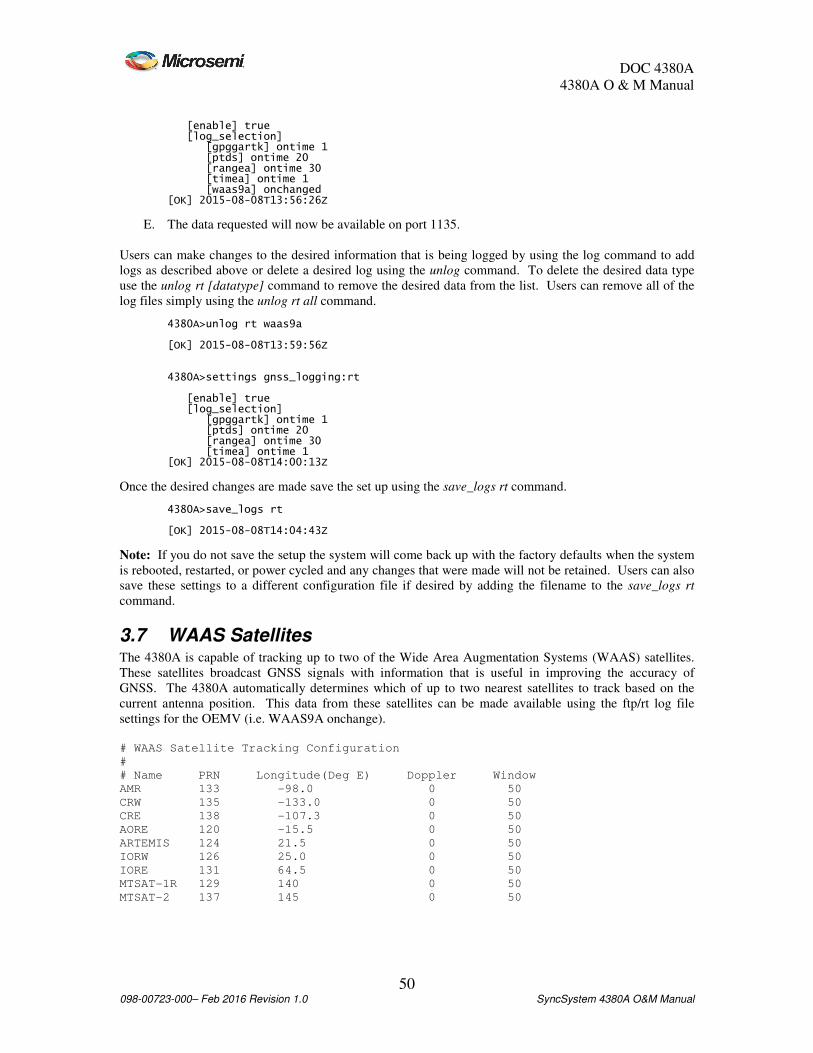
DOC 4380A
4380A O & M Manual
50 098-00723-000– Feb 2016 Revision 1.0 SyncSystem 4380A O&M Manual
[enable] true [log_selection] [gpggartk] ontime 1 [ptds] ontime 20 [rangea] ontime 30 [timea] ontime 1 [waas9a] onchanged [OK] 2015-08-08T13:56:26Z
E. The data requested will now be available on port 1135.
Users can make changes to the desired information that is being logged by using the log command to add
logs as described above or delete a desired log using the unlog command. To delete the desired data type
use the unlog rt [datatype] command to remove the desired data from the list. Users can remove all of the
log files simply using the unlog rt all command. 4380A>unlog rt waas9a [OK] 2015-08-08T13:59:56Z 4380A>settings gnss_logging:rt [enable] true [log_selection] [gpggartk] ontime 1 [ptds] ontime 20 [rangea] ontime 30 [timea] ontime 1 [OK] 2015-08-08T14:00:13Z
Once the desired changes are made save the set up using the save_logs rt command. 4380A>save_logs rt [OK] 2015-08-08T14:04:43Z
Note: If you do not save the setup the system will come back up with the factory defaults when the system
is rebooted, restarted, or power cycled and any changes that were made will not be retained. Users can also
save these settings to a different configuration file if desired by adding the filename to the save_logs rt
command.
3.7 WAAS Satellites The 4380A is capable of tracking up to two of the Wide Area Augmentation Systems (WAAS) satellites.
These satellites broadcast GNSS signals with information that is useful in improving the accuracy of
GNSS. The 4380A automatically determines which of up to two nearest satellites to track based on the
current antenna position. This data from these satellites can be made available using the ftp/rt log file
settings for the OEMV (i.e. WAAS9A onchange).
# WAAS Satellite Tracking Configuration
#
# Name PRN Longitude(Deg E) Doppler Window
AMR 133 -98.0 0 50
CRW 135 -133.0 0 50
CRE 138 -107.3 0 50
AORE 120 -15.5 0 50
ARTEMIS 124 21.5 0 50
IORW 126 25.0 0 50
IORE 131 64.5 0 50
MTSAT-1R 129 140 0 50
MTSAT-2 137 145 0 50

DOC 4380A
4380A O & M Manual
51 098-00723-000– Feb 2016 Revision 1.0 SyncSystem 4380A O&M Manual
3.8 System Verification After the system installation and setup are complete, users can verify the system is operating properly by
looking at several of the system operating parameters to verify the values are correct. If there are no red
LEDs lit on the front panel, the system is operating correctly based on the current user settings. Details of
the system operation can be observed using the following steps:
A. Access the command port.
B. Type status and press enter. This command displays numerous fields that indicate system status.
C. There should be no active alarms on the system. 4380A> status [alarm] no alarm
D. The GNSS Receiver should be tracking at least 4 satellites, the signal description should be good
and the system should show it is locked onto L1 and L2 ([freq] dual) and the receiver should be
reporting an accurate position. [gnss] [auto_positioning] This only applies when the position_mode=auto and [time_remaining] 8 hours, 26 seconds the system has not completed the survey [mode] [desc] tracking[desc] tracking[desc] tracking[desc] tracking [value] 4 [model] [hw_version] OEMV3G-4.00-X2T [name] L12LV [serial_number] DAB08190172 [sw_version] 3.400 [position] [alt] 4.999890000000000e+01[alt] 4.999890000000000e+01[alt] 4.999890000000000e+01[alt] 4.999890000000000e+01 [fixed] false[fixed] false[fixed] false[fixed] false Auto position mode - position_period has not expired [lat] 3.846628110427000e+01[lat] 3.846628110427000e+01[lat] 3.846628110427000e+01[lat] 3.846628110427000e+01 [lon] [lon] [lon] [lon] ----7.744086206042000e+017.744086206042000e+017.744086206042000e+017.744086206042000e+01 [satellite] [number] 7[number] 7[number] 7[number] 7 [signal] [avg] 4.531842422485352e+01 [desc] Good[desc] Good[desc] Good[desc] Good [enum] 2 [freq] dual[freq] dual[freq] dual[freq] dual [max] 4.987799835205078e+01 [min] 3.897399902343750e+01
1. Look at the [satellite] [signal] [desc] field to get an idea on signal quality:
a. Good: Indicates that the signals being received from the GNSS satellites are at an
appropriate level.
b. Fair: The signal level is either too high or too low. GNSS is being received and the
system will function but the levels are not optimal. An in-line amplifier may be required
if the cable loss is too great.
c. Poor: Signal quality is very bad. System will perform very sporadically. An in-line
amplifier will be required if the cable loss is too great.
2. The [satellite] [number] field should be at least 4. If the value is 0 then no satellites are being
tracked. Wait ten-fifteen minutes after the Oscillator Lock light is Green to give the system a
chance to acquire satellites. If the value is still 0 fifteen minutes after the Oscillator Lock
light turned green then there is likely a problem with the antenna setup.
If you are using the manual position mode and the system is reporting satellites but the GNSS
Tracking indicator is off the position entered is incorrect. Verify the position was entered
correctly. If this problem persists, switch the system to the auto mode (position_mode auto)
and allow the system to resurvey the antenna position.

DOC 4380A
4380A O & M Manual
52 098-00723-000– Feb 2016 Revision 1.0 SyncSystem 4380A O&M Manual
3. The [gnss] [satellite] [signal] [freq] field indicates whether single frequency or dual frequency
measurements are being received from the receiver. If only single frequency measurements
are being received then check the antenna and make sure that it is the Novatel (L1/L2)
antenna included with the unit. If you are not using the supplied antenna the system may be
connected to a single frequency (L1) antenna.
E. Both fans should be operating properly. [hardware] [fan] [1] true [2] true
F. Verify the system hardware is operating properly by ensuring the system is displaying the proper
serial number, the outputs are enabled, the power supply status is good and it displays the correct
model #. [mainboard] [EUID] 00:30:96:02:00:00:00:f6 [serialnum] [serialnum] [serialnum] [serialnum] U12121U12121U12121U12121 [type] 4380A [outputs] [enabled] true[enabled] true[enabled] true[enabled] true [slots][slots][slots][slots] [1][1][1][1] [ports][ports][ports][ports] [1][1][1][1] [status] good[status] good[status] good[status] good [2][2][2][2] [status] good[status] good[status] good[status] good [3][3][3][3] [status] good[status] good[status] good[status] good [4][4][4][4] [status] good[status] good[status] good[status] good [power] enabled[power] enabled[power] enabled[power] enabled [type] 4394A[type] 4394A[type] 4394A[type] 4394A [2] [type] empty[type] empty[type] empty[type] empty
[3-6] Should reflect the installed card.
Note: Slots [1-6] will display information based on which slots have cards in them and what type of
cards are installed. If a card is not installed the type will be empty.
G. The warmstart table may be true or false. If the unit has been running for under an hour this may
be false. [warmstartable] true Filter has enough data to warm start the system during a restart/reboot.
H. The power supply status should show both power supplies operating normally. The slots fields
should show which cards are installed in each slot (or empty if no card is present), the port status
for all four outputs are good (=1) and power is enabled. [power][power][power][power] [numsupplies] 2[numsupplies] 2[numsupplies] 2[numsupplies] 2 [supplies] [1] [status] good[status] good[status] good[status] good [type] 4385A[type] 4385A[type] 4385A[type] 4385A [2] [status] good[status] good[status] good[status] good [type] 4385A[type] 4385A[type] 4385A[type] 4385A
I. The system will also report the internal temperature as measured by the unit. [temperature] 37
J. Each of the units hardware conditions is monitored and reported as system health should report
false and have zero active errors.

DOC 4380A
4380A O & M Manual
53 098-00723-000– Feb 2016 Revision 1.0 SyncSystem 4380A O&M Manual
[health] [clock_freq_step] [active] false[active] false[active] false[active] false [occurrences] 0 [clock_phase_step] [active] false[active] false[active] false[active] false [occurrences] 0 [clock_starvation] [active] false[active] false[active] false[active] false [occurrences] 0 [clock_steer] [active] false[active] false[active] false[active] false [occurrences] 0 [clock_wander] [active] false[active] false[active] false[active] false [occurrences] 0 [fan] [1] [active] false[active] false[active] false[active] false [occurrences] 0 [2] [active] false[active] false[active] false[active] false [occurrences] 0 [firmware_version_mismatch] [active] false[active] false[active] false[active] false [occurrences] 0 [gnss_communication_error] [active] false[active] false[active] false[active] false [occurrences] 0 [gnss_error] [active] false[active] false[active] false[active] false [occurrences] 0 [gnss_invalid_fixed_position] [active] false[active] false[active] false[active] false [occurrences] 0 [gnss_tracking] [active] false[active] false[active] false[active] false [occurrences] 0 [hp5071] [electron_multiplier_voltage] [active] false[active] false[active] false[active] false [occurrences] 0 [locked] [active] false[active] false[active] false[active] false [occurrences] 0 [oscillator_control] [active] false[active] false[active] false[active] false [occurrences] 0 [signal_gain] [active] false[active] false[active] false[active] false [occurrences] 0 [leapseconds] [internal_error] [active] false[active] false[active] false[active] false [occurrences] 0 [unknown] [active] false[active] false[active] false[active] false [occurrences] 0 [ocxo_freq_control] [active] false[active] false[active] false[active] false [occurrences] 0
Note: Any GNSS Errors recorded when the unit first starts up may be reported, if so, they will always
have a date of 1 Jan 1998.
K. Each port [1-4] on each output module [1-6] should have zero active errors and the [outputs
disabled] and [outputs unlocked] active blocks should be false. The [power supply] [0-1] active
blocks should also be false. [output_modules] [1] [active] false [occurrences] 0 [ports] [1]

DOC 4380A
4380A O & M Manual
54 098-00723-000– Feb 2016 Revision 1.0 SyncSystem 4380A O&M Manual
[active] false [occurrences] 0 [2] [active] false [occurrences] 0 [3] [active] false [occurrences] 0 [4] [active] false [occurrences] 0 [2] [active] false [occurrences] 0 [ports] [1] [active] false [occurrences] 0 [2] [active] false [occurrences] 0 [3] [active] false [occurrences] 0 [4] [active] false [occurrences] 0 [3] [active] false [occurrences] 0 [ports] [1] [active] false [occurrences] 0 [2] [active] false [occurrences] 0 [3] [active] false [occurrences] 0 [4] [active] false [occurrences] 0 [5] [active] false [occurrences] 0 [ports] [1] [active] false [occurrences] 0 [2] [active] false [occurrences] 0 [3] [active] false [occurrences] 0 [4] [active] false [occurrences] 0 [6] [active] false [occurrences] 0 [ports] [1] [active] false [occurrences] 0 [2] [active] false [occurrences] 0 [3] [active] false [occurrences] 0 [4] [active] false [occurrences] 0 [outputs_disabled] [active] false[active] false[active] false[active] false [occurrences] 0 [over_temperature]

DOC 4380A
4380A O & M Manual
55 098-00723-000– Feb 2016 Revision 1.0 SyncSystem 4380A O&M Manual
[active] false[active] false[active] false[active] false [occurrences] 0 [power_supply] [1] [active] false[active] false[active] false[active] false [occurrences] 0 [2] [active] false[active] false[active] false[active] false [occurrences] 0
L. The [ref_unlocked] fields are reporting the clock status and system performance information. The
reference should be locked ([ref_unlocked] [active] = false). The syscfg active block should be
false. TCXO should also not be reporting any errors. [ref_unlocked] [active] false[active] false[active] false[active] false [occurrences] 0 [syscfg] [active] false[active] false[active] false[active] false [occurrences] 0 [tcxo_failure] [active] false[active] false[active] false[active] false [occurrences] 0
M. Once the system obtains a sufficient amount of clock data the kas2 values will be available. [kas2] [aging] 1.034079545296274e-21 [coldstart_time] 2015-08-05T14:34:30Z [deviation_scalar] 1.000000000000000e+00 [frequency] -1.498015356088144e-13 [phase] 1.390605625690108e-09 [ptd] 8.827366060000000e-10 [steer] -2.226820215582848e-10 [warmstart_time] N/A
N. The leap seconds block should reflect the current # of leap seconds -10. The effective time should
reflect the # of seconds since 1970 the current leap second occurred. The future leap second value
should equal the current value unless there is a leap second pending. [leapseconds] [current] 35 [effectivity_time] 2014-01-01-00:00:00 [future] 35
O. The system should show that NTP is locked (true) and that the system is using the internal clock. [ntp] [locked] true [source] internal refclock
P. The system should report the outputs are enabled [outputs] enabled
Q. The system will also show if the external & internal clocks have been detected and the system will
provide the internal operating temperature. If an external 10MHz signal is not being provided, the
reference:external field will display signal missing. The ocxo_freq_control should also be
between -98 and 98.
Reference_type = hp5071A [frequency] [external] [communications] N/A [locked] true [signal] present [internal] [locked] true [timescale] [clocks] [Cesium1] [1_pps_present_slot_4_port_1] true

DOC 4380A
4380A O & M Manual
56 098-00723-000– Feb 2016 Revision 1.0 SyncSystem 4380A O&M Manual
[communications] N/A [id] 1365 [Cesium2] [1_pps_present_slot_4_port_2] true [communications] N/A [id] 1559 [hp5071] [can_communicate] false [lns] [locked] true [ntp] [locked] true [source] internal refclock [ocxo_freq_control] 2 [OK] 2015-08-08T14:28:03Z
Reference_type = Cesium [external] not monitored [hp5071] [can_communicate] false [internal] locked [lns] locked [locked] true [ocxo_freq_control] 0
R. If the 4380A has a 4393A Card that is actively making measurements the system will report those
measurements as they are computed for each channel. The system will update the status when the
ptd_avg expires and the averaged values are computed. [tic_measurements] [channel] [31] 1.317307692300000e-08 [32] 1.461538461500000e-08 [33] 1.432692307700000e-08 [34] 1.916666666700000e-08
S. The system will report when the status message was reported to the user. [time] 2015-08-08-14:30:26
T. The [unit] will display the system network information, serial number, the startup time (when NTP
Locked), the uptime since the last power cycle, reboot, or restart and the software version running
on the system, and the time the status command was executed. [network] [MAC] 00:30:96:00:00:98 [broadcast] 192.168.150.255 [default_gateway] 192.168.150.1 [ip] 192.168.150.61 [netmask] 255.255.255.0 [serial_number] SP00235 [start] 2013-07-18-12:50 [uptime] 4 hours, 42 minutes, 16 seconds [ver] Sync System-5-1-0 [OK] 2015-08-08T14:30:26Z
U. Send the settings command and verify the user defined set up parameters are correct. 4380A>settings [command_port] [prompt] [enable] true [text] 4380A> [diaglog] [clock] info [cpld4370] info [gnss] info [kas2] debug [lnsrawstate] info [smcp] info [software] info [tagnss] info [timecode] info

DOC 4380A
4380A O & M Manual
57 098-00723-000– Feb 2016 Revision 1.0 SyncSystem 4380A O&M Manual
[4380] info [tsgather] info [warmstart] info [gnss] [antenna_delay] 2.374500000000000e-07 [antenna_voltage] 0.000000000000000e+00 [datum] wgs84 [mask_angle] 1.000000000000000e+01 [positioning] [auto_hours] 1.200000000000000e+01 [manual_position] [altitude] 1.957604000000000e+02 [latitude] 3.992277932811000e+01 [longitude] -7.758567672868000e+01 [mode] manual [tracking_timeout] 1800 [gnss_logging] [ftp] [compression] false [enable] true [file_count] 10 [filename] [digits] 3 [prefix] user [suffix] [type] timestamp [interval] 5 [log_selection] [bestposa] ontime 7200 [ionutca] ontime 7200 [rangea] ontime 60 [rawalma] onchanged [rawephema] onchanged [rxhwlevelsa] ontime 60 [waas9a] onchanged [rt] [enable] true [log_selection] [gpggartk] ontime 1 [ptds] ontime 20 [rangea] ontime 30 [timea] ontime 1 [waas9a] onchanged [hardware] [enable_fp_button] true [slots] [1] [4394A] [ports] [1] [pps_period] 1.000000000000000e+00 [pps_width] 1.000000000000000e-04 [type] pps [2] [pps_period] 1.000000000000000e+00 [pps_width] 1.000000000000000e-04 [type] pps [3] [format] B [signal_word] 0 [type] irig [4] [format] B [signal_word] 0 [type] irig [2] [4394A] [ports] [1] [pps_period] 1.000000000000000e+00 [pps_width] 1.000000000000000e-04 [type] pps [2] [pps_period] 1.000000000000000e+00 [pps_width] 1.000000000000000e-04 [type] pps [3] [format] B [signal_word] 0

DOC 4380A
4380A O & M Manual
58 098-00723-000– Feb 2016 Revision 1.0 SyncSystem 4380A O&M Manual
[type] irig [4] [format] B [signal_word] 0 [type] irig [4] [4395] [ports] [1] [2] [3] [4] [5] [empty] [6] [4387] [ports] [1] [2] [3] [4] [ptd_port] [averaging_interval] 10 [reference] [external] [type] hp5071a [source] external [smcp] [syscfg] [mode] standalone [OK] 2015-08-08T14:31:37Z
V. At this point if there are no alarms the 4380A is functioning properly. Network connectivity
should be checked to ensure that data is being transmitted properly.
W. Log files will be available to the ftp user after the specified log period has expired as long as the
ftp logging is enabled. If in the auto positioning mode the rinex file will be available after the
auto_positioning period has expired. The real-time logs will be available on Port 1135.
X. TIC Measurements will be available (Raw = 2101, Avg = 2100) if one or more 4393A cards are
installed and there are 1PPS signals detected on the input ports.
Y. If operations are normal and the setup is proper type save at the command prompt to save the
system default settings or save filename to save the settings to a different configuration file. Use
the save_logs ftp and save_logs rt commands to save the ftp or real time logging default settings
or add a filename to these commands to save the settings to a different configuration file.
Note: If you do not save the user default settings the system will come up with the factory default
values the next time the system reboots or is power cycled.
DOC 4380A
4380A O & M Manual
59 098-00723-000– Feb 2016 Revision 1.0 SyncSystem 4380A O&M Manual
4 Theory of Operations Two distinct tasks are performed by the 4380A: collection of GNSS measurement data or the deterministic
alignment to an external source and the generation of timing signals. Because the generation of timing
signals requires that events (e.g., clock steering) occur at very specific times, operational precedence is
always given to timing tasks. As a result, any operations concerning the collection and storage of GNSS
data are postponed until all timing operations have been completed.
4.1 Generation of Timing Signals A rubidium standard (when installed) serves as the short term and holdover with no GNSS frequency
reference for the 4380A. The frequency of the Rubidium is measured and the low noise OCXO is steered
to be on frequency. The frequency adjustments made to the OCXO allow it to be aligned with
UTC(USNO) which is the source of GNSS time and is used as a long term frequency reference. In doing
this, the 4380A exhibits the short-term frequency stability characteristics of the Rubidium while exhibiting
the long-term characteristics of GNSS. The OCXO provides low phase noise performance for the 10 MHz
outputs.
The 10MHz output provided by the OCXO serves as the time base for the 4380A. All timing signals (e.g.,
1 PPS, IRIG-B, 10 MHz) are derived from this reference and thus exhibit the same frequency and phase
characteristics. The 100 MHz TCXO which is the clock for the main FPGA is divided by 10 and phase
locked to the OCXO 10 MHz output. The rear panel 10 MHz plug in card has a D/A converter which is
used along with a sine look up table to provide a 10 MHz signal from the 100 MHz internal clock. This
D/A output is then filtered and distributed to the four outputs of the plug in card. The FPGA which is
clocked by the 100 MHz TCXO provides 1 PPS and serial time codes which are used by the 1 PPS/DC
IRIG and AM IRIG cards to produce 1 PPS and IRIG time codes.
4.2 GNSS The GNSS receiver locks its internal reference to the 10MHz signal provided by the OCXO frequency
reference. A 1 PPS signal is then generated by the receiver which has a fixed phase relationship to the
frequency reference. Measurements of this PPS are made to determine its offset to UTC(USNO) and this
information is passed to the CPU via a serial port. These measurements are used in generating a timescale
that estimates the clock offset from UTC(USNO). The CPU slowly adjusts the frequency of the OCXO to
align the PPS to be coincident with UTC(USNO), Depending on the type of frequency reference, this
adjustment period varies from a day (rubidium) to several months (external cesium), although rough
alignment to within 10 ns occurs on the order of a few hours in either case. Commands are sent by the
CPU to the Low Noise Synthesizer clock to adjust the analog control voltage to the OCXO as a means of
affecting this steering.
4.3 Output Signals The PPS signal from the GNSS receiver/reference source is used to align both the IRIG-B signal and the
CPU clock to UTC(USNO). At startup this PPS is used to align the internally generated 1 PPS and IRIG-B
signal with the correct 10 MHz clock cycle. From that point on the 1 PPS and IRIG-B signals are kept on
time by using the OCXO 10MHz signal as its reference. The 1 PPS signal from the GNSS receiver
generates an interrupt to the ARM 9 processor which serves as an indicator of the top-of-second. This is
used by the CPU along with messages received from the GNSS receiver to set the CPU time to
UTC(USNO). In doing this, the CPU can serve as a stratum-1 network time protocol (NTP) server and
provide time to other computers and systems on the network. The OCXO control voltage is polled every
LNS time constant in order to weed out transients due to steering allowing the system to accurately
determine if the OCXO control voltage is at a minimum or maximum value. The averaging of this control
voltage provides more stable steering over time.

DOC 4380A
4380A O & M Manual
60 098-00723-000– Feb 2016 Revision 1.0 SyncSystem 4380A O&M Manual
The fiber optic outputs from the 4372A/4372A-T module, when plugged into a Master 4380A, contain a
proprietary bit stream with 1 PPS marker and time code information. The Slave 4380A decodes this bit
stream, extracts the time code, and steers its internal OCXO to the frequency and phase of the fiber signal.
When shipped from the factory, the downstream 4380As will automatically switch to input B upon loss of
input A. When Fiber A is restored, the unit will automatically switch back to input A after input A is
detected as good for 60 seconds. The user can select manual switching or disable the automatic return to
input A as a reference after input A has failed. A TSC-4340A fiber optic distribution chassis may be
connected to an output of the 4372A module to provide up to 8 outputs which can be connected to
downstream 4380As.
The 4393A Time Interval Counter (TIC) provides the capability to measure up to four external 1PPS
sources against the internal 1PPS. The measurement data is collected by the unit and provided on telnet
ports 2100 and 2101. Port 2100 is the averaged measurement, where the default is 10 seconds. The
averaging time can be changed to 1, 10, 20 60, or 300 seconds using the ptdavg command. Port 2101
provides one second measurement data. The 4393A can be used in any of the slots in the 4380A. Multiple
4393A cards can be installed in the unit when more than four 1PPS measurements are required. Data
collected can be used by an external system to create a paper clock based on the measurements.
4.4 GNSS Data Collection GNSS measurement data is available to users in a variety of log formats. The 4380A uses a Novatel OEM6
(dual-frequency and WAAS capable) as its GNSS receiver and thus any logs generated by the receiver are
available to users. For a complete description of logs and their formats refer to the OEM6 manual at
http://www.novatel.com.
Logs on the 4380A are handled in two ways. They are either stored in volatile memory for retrieval by
FTP or they are output to the Ethernet port in real-time. Logs stored in volatile memory are referred to as
ionospheric logs and may be compressed to increase the capacity of the storage area. A total of 16 MB is
dedicated to the storage of ionospheric logs and as storage capacity is approached older logs will be deleted
to make room for newer logs. Real-time logs are logs requested by the user for output to the Ethernet port
on the rear panel of the 4380A. They are provided to the user in a timely manner but are not stored on the
system.
All logs must be enabled at startup through the use of configuration files. Ionospheric logs are specified in
the ftp configuration file and real-time logs are specified in the real-time configuration file. Ionospheric
logs are always generated by the 4380A but the Ethernet port (1135) must be configured at startup in order
to receive the desired real-time logs.
4.5 Startup Sequence A very specific sequence exists for starting each of the internal devices within the 4380A. This sequence
exists to ensure that the unit generates the appropriate timing outputs and that they are all in sync with each
other. Startup time of the 4380A varies from 5 to 45 minutes depending upon how long the unit has been
powered off but the timing outputs are not enabled until 1 PPS and 10 MHz are accurate.
The 10MHz frequency reference measurements are made on either the internal OCXO, Rb oscillator, or an
external Cs source. In either case the 4380A waits for the frequency reference to indicate that it has
warmed up and is providing a stable signal. The internal Rb is generally warm and operational within 10
minutes but external references may take longer. Once the frequency reference is operational, the front
panel indicator “SYNC” will illuminate green. This indicates that the frequency reference is the 4380A is
locked to the frequency reference and the startup operations will continue.
Once the frequency is locked, the GNSS receiver is restarted using the 10 MHz signal as its reference. The
receiver will begin generating the 1 PPS outputs but they will not be aligned to UTC(USNO). A search
algorithm is used by the GNSS receiver which attempts to acquire and track the signal received from GNSS

DOC 4380A
4380A O & M Manual
61 098-00723-000– Feb 2016 Revision 1.0 SyncSystem 4380A O&M Manual
satellites. This process usually takes 5 to 10 minutes but may take as long as 30 minutes depending upon
how long the 4380A has been powered off. After four satellites are being tracked by the GNSS receiver,
the PPS output is adjusted so that it is aligned with UTC(USNO). The green “SYNC” light on the front
panel will also illuminate to indicate to the user that the system is currently tracking the GNSS signal.
To serve as a Stratum-1 network time protocol (NTP) server requires that the system’s CPU clock be
aligned with UTC(USNO). The process of locking the CPU clock to UTC(USNO) requires setting the
system time to UTC(USNO) and using the PPS received from the GNSS receiver to continuously steer the
CPU clock. If the unit has been powered off for a long period of time the CPU time may be multiple
seconds off. In these cases, a coarse adjustment of system time is performed and then the startup sequence
is restarted. This process should only happen once and only in cases where the system has been powered
off.

DOC 4380A
4380A O & M Manual
62 098-00723-000– Feb 2016 Revision 1.0 SyncSystem 4380A O&M Manual
5 Maintenance The recommended maintenance schedule for the 4380A is outlined in Table 6. Although this schedule is
sufficient for most applications, it may be necessary to increase the number of scheduled maintenance
events for extremely dusty or dirty environments. Contact Microsemi if there are questions about the
scheduled maintenance cycle.
A minimal amount of maintenance is required for the 4380A. It is designed to operate continuously over
long periods of time with little to no interaction. The primary factor in maintaining a working unit is to
verify that it remains dust free and the antenna and antenna cable are in good condition. The following
maintenance schedule is applicable.
Interval Maintenance Required
Monthly None
Semi-Annual None
Annual 1. Fan Filter1
2. Antenna & Antenna Cable Inspection
Table 6 Maintenance Schedule
5.1 Fan Filter The fan filters helps protect the system from accumulating dust inside the unit as well and allows the fans
to provide the proper level of cooling for the internal components. It is important to keep this filter clean to
allow the proper level of air flow to prevent the system from overheating. To clean the filter:
1. Remove the fan assembly from the front by loosening the two captive screws.
2. Remove the filter from the fan assembly.
3. Use a vacuum cleaner to clean the fan filter of any accumulated dust.
4. Re-install the filter and assembly into the chassis. Take care to feed the cable into the chassis
while inserting the fan assembly.
5.2 Antenna and Antenna Cable Inspection The Antenna and antenna cables are a common source of failure because they are exposed to harsh
environmental elements. The following process outlines the steps required in performing an inspection of
the antenna and antenna cable.
1. Follow the antenna cable from the rear of the 4380A to the antenna. Look for any severe bends in
the cable or damage to the shielding of the cable.
2. Remove any severe bends in the cable and replace any cables that have damaged shielding.
3. Examine the portions of the cables that are exposed to the elements. Look for signs of excessive
weathering such as a deterioration of the outermost insulator. Replace any cables that appear
severely weathered.
4. Inspect the antenna. Clean any buildup of dirt or other contaminants from the surface of the
antenna. These contaminants may degrade the strength of the GNSS signal. If the antenna has
been damaged by the weather, replace it.
5. Verify that the antenna is still securely mounted.
1 In extreme operating environments it may be necessary to clean the fan filter more frequently.
DOC 4380A
4380A O & M Manual
63 098-00723-000– Feb 2016 Revision 1.0 SyncSystem 4380A O&M Manual
6 Troubleshooting The following section provides some basic troubleshooting information to assist users in case they suspect
there is an issue with the system.
6.1 Front Panel Indications You can use the front panel indicators to assess the status and operation of the unit. Under normal
operating conditions the user should see:
• Green Status Indicator is green on both power supplies
• The front panel clock should display the last two digits of the year, the correct Julian Date (see
Appendix D.) and the correct time (UTC). The time should also increment each second.
• The Alarm Light is Off
• The Sync and Outputs lights are green.
6.2 Alarm Light The alarm light will turn red when the unit has detected a hardware failure or an event has occurred that
may cause the timing signals output by the unit to be outside of their specifications.
• Red (Flashing)
o Non Critical System alarm
System failed validation/startup tests.
Either power supply missing/failed or without AC/DC input power.
• Red (Steady)
o Any output module reporting a failure or is not locked to the reference
o GNSS has not been not tracking for at least 30 minutes or there is a hardware error
o Reference clock wander has exceeded 100 ns from UTC
o The Rubidium is unlocked.
o Over temperature (65 C)
o External Reference
System is unable to communicate with the external reference source or,
10MHz input from the external reference is missing and
Reference=external.
o If syscfg in enabled, use the status syscfg:errors command to get the current list of
configuration alarms.
If the alarm light is on users can determine the exact cause of the alarm by accessing the command port and
typing the alarms command and obtain a list of the current alarms.
If the alarm light was on and is currently off, users can connect to the command port and type the command
status health to view alarm occurrences or the syslog command to obtain the list of errors from the system
log file.
6.3 Power Supplies The system has two power supplies and is capable of operating from either supply in the event one of them
fails. If one of the status indicators on the power supply front panel is red there is a problem with that
supply. The front panel alarm light should also be on. Power supply #1 is on the left and Power Supply #2
is on the right. The possible problems are listed below:
• Power Supply has failed
• Internal Fuse is open

DOC 4380A
4380A O & M Manual
64 098-00723-000– Feb 2016 Revision 1.0 SyncSystem 4380A O&M Manual
• Power Supply is unplugged, make sure the power supply is plugged in
• Power Source has failed; check to ensure the power source is available and connected to the rear
panel of the unit.
Users can also check the current system using the alarm and the status health:power_supply commands to
check the system status. 4380A> alarm power_supply:2 -- AC/DC supply missing, or hardware error 4380A>status health:power_supply [1] [active] false [occurrences] 0 [2] [active] true[active] true[active] true[active] true [occurrences] 1[occurrences] 1[occurrences] 1[occurrences] 1 [set][set][set][set] [what] AC/DC supply missing, or hardware error[what] AC/DC supply missing, or hardware error[what] AC/DC supply missing, or hardware error[what] AC/DC supply missing, or hardware error [when] [when] [when] [when] 2015201520152015----08080808----05050505----14:26:02.52314:26:02.52314:26:02.52314:26:02.523 [OK] 2015-08-08T14:38:52Z
If the fault condition has cleared, users are able to check the events in the system using the status
health:power_supply commands to check on events that occurred earlier. 4380A>status health:power_supply [1] [active] false [occurrences] 0 [2] [active] false [cleared][cleared][cleared][cleared] [what] No errors[what] No errors[what] No errors[what] No errors [when] [when] [when] [when] 2015201520152015----08080808----06060606----16:14:38.87416:14:38.87416:14:38.87416:14:38.874 [occurrences] 1[occurrences] 1[occurrences] 1[occurrences] 1 [set] [what] AC/DC supply missing, or hardware error [when] 2015-08-05-14:26:02.523
6.4 Outputs Indicator This indicator provides the status for the NTP Server and system outputs.
This indicator will turn RED if the 4380A detects a hardware fault with one or more of the output modules.
Verify the output modules are locked to reference and the outputs are enabled using the status
health:outputs_disabled command and verify both active and occurrences = 0. 4380A>status health:outputs_disabled [active] false[active] false[active] false[active] false [cleared] [what] Outputs are enabled [when] 2015-08-06-20:51:14.207 [occurrences] 0 [set] [what] Outputs are disabled [when] 2015-08-05-14:25:56.817 [OK] 2015-08-08T14:41:32Z
Users can determine which output module(s) has failed:
• Based on which systems the 4380A is driving are no longer operating properly
• By unplugging the output modules, one at a time, to see which output module was at fault.
Note: If this does not work there may be more than one output module that failed. Pull them all
and reinsert them one at time to see which one(s) cause a FAULT.

DOC 4380A
4380A O & M Manual
65 098-00723-000– Feb 2016 Revision 1.0 SyncSystem 4380A O&M Manual
• By using the status health:output_modules command and/or the syslog command and checking
both the active = true and/or occurrences is greater than 0. 4380A>status health:output_modules [1] [active] false [occurrences] 0 [ports] [1] [active] false [occurrences] 0 [2] [active] false [occurrences] 0 [3] [active] false [occurrences] 0 [4] [active] false [occurrences] 0 [2] [active] false [occurrences] 0 [ports] [1] [active] false [occurrences] 0 [2] [active] false [occurrences] 0 [3] [active] false [occurrences] 0 [4] [active] false [occurrences] 0 [3] [active] false [occurrences] 0 [ports] [1] [active] false [occurrences] 0 [2] [active] false [occurrences] 0 [3] [active] false [occurrences] 0 [4] [active] false [occurrences] 0 [5] [active] false [occurrences] 0 [ports] [1] [active] false [occurrences] 0 [2] [active] false [occurrences] 0 [3] [active] false [occurrences] 0 [4] [active] false [occurrences] 0 [6] [active] false [occurrences] 0 [ports] [1] [active] false [occurrences] 0 [2] [active] false

DOC 4380A
4380A O & M Manual
66 098-00723-000– Feb 2016 Revision 1.0 SyncSystem 4380A O&M Manual
[occurrences] 0 [3] [active] false [occurrences] 0 [4] [active] false [occurrences] 0
The Outputs indicator will be flashing green when the NTP server is locked and capable of providing time
within specifications to other systems on the network and the outputs are not enabled.. When the NTP
Server is operating outside of its specification the indicator will flashing red. To look at the current status
of the internal NTP Server use the status reference:ntp command. If the NTP Server is operating properly
the user will see the following: 4380A>status reference:ntp [locked] true [source] internal refclock [OK] 2015-08-08T15:01:03Z
6.5 GNSS Performance There are several factors that could impact the performance of the GNSS receiver.
6.5.1 Poor GNSS Receiver Performance There are several issues that can cause poor performance with the GNSS receiver. This may be reflected in
the signal quality parameter or the fact the 4380A Sync indicator flashes red periodically. Use the status
gnss command to look at the current system status. 4380A>status gnss [mode] [desc] tracking [value] 4 [model] [hw_version] OEMV3G-4.00-X2T [name] L12LV [serial_number] DAB08400198 [sw_version] 3.400 [position] [alt] 5.050310000000000e+01 [fixed] true [lat] 3.846628161218000e+01 [lon] -7.744086549511999e+01 [satellite] [number] 8 [signal] [avg] 4.723037719726562e+01 [desc] Good [enum] 2 [freq] dual [max] 4.942499923706055e+01 [min] 4.031800079345703e+01
• Poor antenna location.
o Make sure that there are no obstructions between the GNSS antenna and the sky. If you are
inside a building, surrounded by tall buildings, or in a tunnel the GNSS antenna will not have
a clear view of the sky.
o The GNSS receiver requires signals from at least four satellites, even partial obstructions can
prevent your GNSS receiver from functioning properly.
• Ensure the mask angle is not set too low or too high.
o If set too low the receiver might not be able to track the satellites because of obstructions
o If set too high, the receiver will not be able to use all of the available satellites to determine a
fix and determine the correct time.
o Ensure the mask angle is correct using the settings gnss:mask_angle command. Default = 10
degrees.
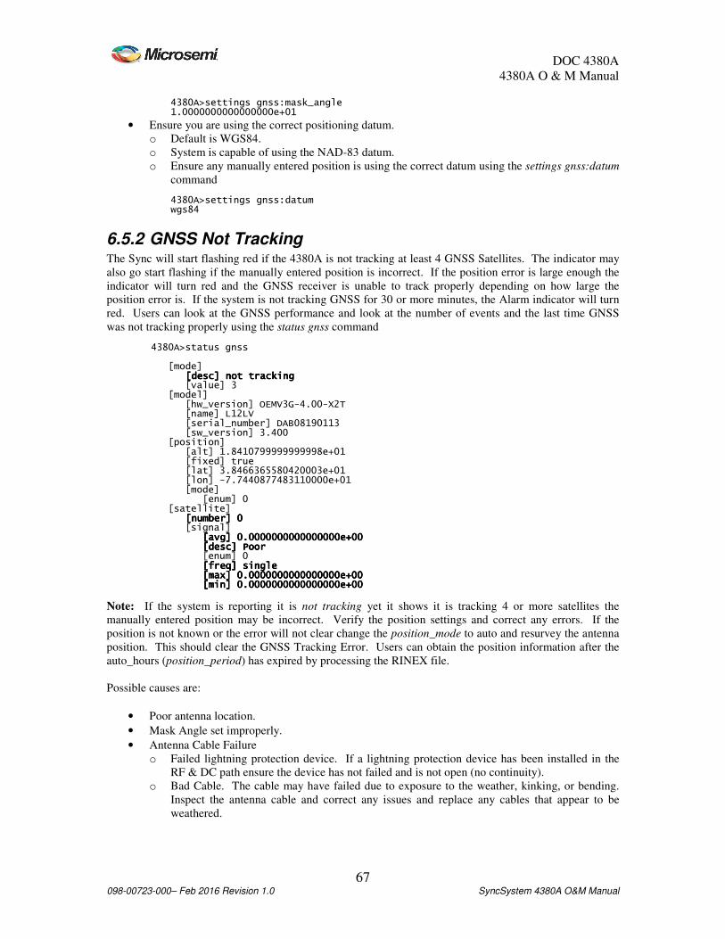
DOC 4380A
4380A O & M Manual
67 098-00723-000– Feb 2016 Revision 1.0 SyncSystem 4380A O&M Manual
4380A>settings gnss:mask_angle 1.0000000000000000e+01
• Ensure you are using the correct positioning datum.
o Default is WGS84.
o System is capable of using the NAD-83 datum.
o Ensure any manually entered position is using the correct datum using the settings gnss:datum
command 4380A>settings gnss:datum wgs84
6.5.2 GNSS Not Tracking The Sync will start flashing red if the 4380A is not tracking at least 4 GNSS Satellites. The indicator may
also go start flashing if the manually entered position is incorrect. If the position error is large enough the
indicator will turn red and the GNSS receiver is unable to track properly depending on how large the
position error is. If the system is not tracking GNSS for 30 or more minutes, the Alarm indicator will turn
red. Users can look at the GNSS performance and look at the number of events and the last time GNSS
was not tracking properly using the status gnss command 4380A>status gnss [mode] [desc] not tracking[desc] not tracking[desc] not tracking[desc] not tracking [value] 3 [model] [hw_version] OEMV3G-4.00-X2T [name] L12LV [serial_number] DAB08190113 [sw_version] 3.400 [position] [alt] 1.8410799999999998e+01 [fixed] true [lat] 3.8466365580420003e+01 [lon] -7.7440877483110000e+01 [mode] [enum] 0 [satellite] [number] 0[number] 0[number] 0[number] 0 [signal] [avg] 0.0000000000000000e+00[avg] 0.0000000000000000e+00[avg] 0.0000000000000000e+00[avg] 0.0000000000000000e+00 [desc] Poor[desc] Poor[desc] Poor[desc] Poor [enum] 0 [freq] single[freq] single[freq] single[freq] single [max] 0.000000000000[max] 0.000000000000[max] 0.000000000000[max] 0.0000000000000000e+000000e+000000e+000000e+00 [min] 0.0000000000000000e+00[min] 0.0000000000000000e+00[min] 0.0000000000000000e+00[min] 0.0000000000000000e+00
Note: If the system is reporting it is not tracking yet it shows it is tracking 4 or more satellites the
manually entered position may be incorrect. Verify the position settings and correct any errors. If the
position is not known or the error will not clear change the position_mode to auto and resurvey the antenna
position. This should clear the GNSS Tracking Error. Users can obtain the position information after the
auto_hours (position_period) has expired by processing the RINEX file.
Possible causes are:
• Poor antenna location.
• Mask Angle set improperly.
• Antenna Cable Failure
o Failed lightning protection device. If a lightning protection device has been installed in the
RF & DC path ensure the device has not failed and is not open (no continuity).
o Bad Cable. The cable may have failed due to exposure to the weather, kinking, or bending.
Inspect the antenna cable and correct any issues and replace any cables that appear to be
weathered.

DOC 4380A
4380A O & M Manual
68 098-00723-000– Feb 2016 Revision 1.0 SyncSystem 4380A O&M Manual
o Improper Antenna Cable. The cable may be either too long or the improper type. Microsemi
recommends using low loss coaxial cables for the GNSS antenna cable. Cable losses cannot
exceed 10dB when using the antenna supplied with the 4380A.
• Antenna Failure
o Loss of Power. Antenna requires 5-18Vdc to operate properly. Disconnect the cable from the
antenna and measure the DC voltage between the center pin (+) and shield (-) to ensure the
antenna operating voltage is present. If not, check the cable continuity and DC Power Source.
Note: The DC Power source may be a BIAS Tee or the 4380A. Ensure the antenna voltage is
available from the proper source.
o Failed Antenna. If the DC Power source is available and at the proper level and the antenna
cable continuity is good, replace the antenna.
• User entered an invalid position
o GNSS Tracking indicator is OFF. Enter the correct position for the antenna. Use the status
health:gnss_error command to look at the status of the GNSS hardware.
6.6 Internal Clocks If you suspect there may be an issue with the internal clocks use the status health and status reference
commands to look at the status of the internal clocks.
Note: The example below has been edited to show the relevant fields in the system health status for the
clocks. 4380A>status health [clock_freq_step] [active] false[active] false[active] false[active] false [occurrences] 0 [clock_phase_step] [active] false[active] false[active] false[active] false [occurrences] 0 [clock_starvation] [active] false[active] false[active] false[active] false [occurrences] 0 [clock_steer] [active] false[active] false[active] false[active] false [occurrences] 0 [clock_wander] [active] false[active] false[active] false[active] false [occurrences] 0 4380A>status reference [frequency] [external] [communications] N/A [locked] true [signal] present [internal][internal][internal][internal] [locked] true[locked] true[locked] true[locked] true [timescale] [clocks] [Cesium1] [1_pps_present_slot_4_port_1] true [communications] N/A [id] 1365 [Cesium2] [1_pps_present_slot_4_port_2] true [communications] N/A [id] 1559 [hp5071] [can_communicate] false [lns][lns][lns][lns] [locked] true[locked] true[locked] true[locked] true [ntp] [locked] true [source] internal refclock

DOC 4380A
4380A O & M Manual
69 098-00723-000– Feb 2016 Revision 1.0 SyncSystem 4380A O&M Manual
[ocxo_freq_control] 2[ocxo_freq_control] 2[ocxo_freq_control] 2[ocxo_freq_control] 2 [OK] 2015-08-08T14:46:32Z
Users can also check the status of the time scale to ensure the UTC offset value [ptd] is under +/- 100 ns
from UTC and the clock is being steered 4380A>status kas2 [aging] 1.100073337398044e-21 [coldstart_time] 2015-08-05T14:34:30Z [deviation_scalar] 1.000000000000000e+00 [frequency] -1.286384790183644e-13 [phase] 1.287980469829245e-09 [ptd] 1.463024104000000e[ptd] 1.463024104000000e[ptd] 1.463024104000000e[ptd] 1.463024104000000e----09090909 [steer] [steer] [steer] [steer] ----2.227125689387322e2.227125689387322e2.227125689387322e2.227125689387322e----10101010 [warmstart_time] N/A
Users may use the jam_sync command to synchronize the system 1 PPS to the reference input. 4380A>jam_sync [OK] 2015-08-08T15:56:04Z
Then use the status kas2 command to ensure the internal clock offset has jumped to the reference. 4380A>status kas2 [aging] 2.498557764780871e-24 [coldstart_time] 2015-08-08T14:59:54Z [deviation_scalar] 1.000000000000000e+00 [frequency] 7.612250351220100e-13 [phase] -7.549350148732179e-09 [ptd] -7.227491861000000e-09 [steer] -2.218719571828842e-10 [warmstart_time] N/A [OK] 2015-08-08T15:57:29Z
Note: Using the jam_sync command will cause the internal clock to steer very hard in order to synchronize
with the external reference.
6.7 External Reference If you suspect there may be issues with the external reference use the status health and status reference
commands to look at the status of the external reference and internal clocks.
Note: The example below has been edited to show the relevant fields in the system health status for the
clocks. 4380A>status health [clock_freq_step] [active] false[active] false[active] false[active] false [occurrences] 0 [clock_phase_step] [active] false[active] false[active] false[active] false [occurrences] 0 [clock_starvation] [active] false[active] false[active] false[active] false [occurrences] 0 [clock_steer] [active] false[active] false[active] false[active] false [occurrences] 0 [clock_wander] [active] false[active] false[active] false[active] false [occurrences] 0
Reference_type = cesium 4380A>status reference [frequency] [external] [communications] N/A[communications] N/A[communications] N/A[communications] N/A

DOC 4380A
4380A O & M Manual
70 098-00723-000– Feb 2016 Revision 1.0 SyncSystem 4380A O&M Manual
[locked] true[locked] true[locked] true[locked] true [signal] present[signal] present[signal] present[signal] present [internal] [locked] true [hp5071][hp5071][hp5071][hp5071] [can_communicate] false[can_communicate] false[can_communicate] false[can_communicate] false [lns] [locked] true [ntp] [locked] true [source] internal refclock [ocxo_freq_control] 5 [OK] 2013-09-04T14:10:03Z
Reference_type = hp5071a 4380A>status reference [external] locked [hp5071] [can_communicate] true[can_communicate] true[can_communicate] true[can_communicate] true [electron_multiplier_voltage] 1.142000000000000e+03[electron_multiplier_voltage] 1.142000000000000e+03[electron_multiplier_voltage] 1.142000000000000e+03[electron_multiplier_voltage] 1.142000000000000e+03 [osc_freq_control] [osc_freq_control] [osc_freq_control] [osc_freq_control] ----1.179000000000000e1.179000000000000e1.179000000000000e1.179000000000000e----01010101 [power] AC[power] AC[power] AC[power] AC [serial_number] US38390769(S)[serial_number] US38390769(S)[serial_number] US38390769(S)[serial_number] US38390769(S) [signal_gain] 1.440000000000000e[signal_gain] 1.440000000000000e[signal_gain] 1.440000000000000e[signal_gain] 1.440000000000000e----01010101 [internal] locked [lns] locked [locked] true [ocxo_freq_control] 2 [OK] 2015-08-08T14:52:09Z
Users can also check the status of the time scale to ensure the UTC offset value [ptd] is under +/- 100 ns
from UTC and the clock is being steered 4380A>status kas2 [aging] 1.115608749949706e-21 [coldstart_time] 2015-08-05T14:34:30Z [deviation_scalar] 1.000000000000000e+00 [frequency] -1.291366569251172e-13 [phase] 1.282074219678497e-09 [ptd] 1.241064798000000e[ptd] 1.241064798000000e[ptd] 1.241064798000000e[ptd] 1.241064798000000e----09090909 [steer] [steer] [steer] [steer] ----2.227252349257469e2.227252349257469e2.227252349257469e2.227252349257469e----10101010 [warmstart_time] N/A [OK] 2015-08-08T14:53:27Z
If there is an issue with the 10MHz Input it will show in the status reference:frequency:external command.
The front panel Alarm light will be RED and the Oscillator Lock light will be OFF. 4380A>status reference:frequency:external [communications] N/A [locked] false [signal] missing[signal] missing[signal] missing[signal] missing [OK] 2015-08-08T14:58:00Z
When the 10 MHz signal is restored the Alarm light will remain on, the Oscillator lock light will remain out
and the GNSS Tracking indicator may go out for ~30 seconds. Once the GNSS Tracking indicator is lit the
system will report the kas2 values.
If the 4380A is unable to communicate with the external reference the operator will get an indication of the
error. The front panel Alarm light will be RED and the Oscillator Lock light will be OFF. 4380A>status alarm ref_unlocked ref_unlocked ref_unlocked ref_unlocked -------- cannot communicate with devicecannot communicate with devicecannot communicate with devicecannot communicate with device 4380A>status reference [external] cannot communicate[external] cannot communicate[external] cannot communicate[external] cannot communicate [hp5071] [can_communicate] false [electron_multiplier_voltage] 1.142000000000000e+03

DOC 4380A
4380A O & M Manual
71 098-00723-000– Feb 2016 Revision 1.0 SyncSystem 4380A O&M Manual
[osc_freq_control] -1.178000000000000e-01 [power] AC [serial_number] US38390769(S) [signal_gain] 1.440000000000000e-01 [internal] locked [lns] unlocked [locked] false [ocxo_freq_control] 2 [OK] 2015-08-08T14:59:57Z
Once communications are restored the system will clear the alarm indications and resume normal
operations.
6.8 PTD Value is Noisy The PTD (UTC Offset) value will be much noisier when the 4380A is in the dynamic mode and during the
positioning period while in the AUTO mode.
• Static position users should use the AUTO mode when the antenna position is unknown. After the
auto_hours has expired, the antenna position will be determined by the receiver and the 4380A
will switch to the fixed position mode. Once this happens, the PTD value will be significantly
quieter. Users should put the system in Manual positioning mode and save settings once AUTO
mode is complete in order to prevent AUTO mode from occurring after a power failure.
• If the antenna position is known, users should put the system in Manual positioning mode and
enter the latitude, longitude, and altitude of the antenna.
• Poor antenna location and/or multipath issues can cause instabilities, relocate the antenna to a
more suitable location. 4380A>settings gnss [antenna_delay] 0.000000000000000e+00 [antenna_voltage] 0.000000000000000e+00 [datum] wgs84 [mask_angle] 1.000000000000000e+01 [positioning] [auto_hours] 1.2000[auto_hours] 1.2000[auto_hours] 1.2000[auto_hours] 1.200000000000000e+0100000000000e+0100000000000e+0100000000000e+01 [manual_position] [altitude] 1.592729000000000e+03 [latitude] 4.001941422777778e+01 [longitude] -1.052390962444445e+02 [mode] auto[mode] auto[mode] auto[mode] auto
6.9 Over Temperature and Fans The 4380A monitors the internal temperature will trigger an alarm to be displayed on the front panel and
the status alarm list when the internal temperature reaches or exceeds 65ºC. To check the current
temperature on the system use the status hardware:temperature command. 4380A>status hardware:temperature 31
Users can look to see if the unit had any temperature issues by using the status health:over_temperature
command 4380A>status health:over_temperature [active] false [occurrences] 0
The 4380A monitors the fans on the front panel to ensure they are operating, to check the current status of
the fans use the status hardware:fan command. Both fans should show a status of 1 indicating it is
operating normally. 4380A>status hardware:fan [1] true [2] true

DOC 4380A
4380A O & M Manual
72 098-00723-000– Feb 2016 Revision 1.0 SyncSystem 4380A O&M Manual
Users can look to see if the unit had any issues with either of the fans by using the status health:fan
command 4380A>status health:fan [1] [active] false [occurrences] 0 [2] [active] false [occurrences] 0
Note: If the unit is reporting an over temperature condition and the fans are not reporting an error, ensure
the ambient temperature is less than 65ºC and the fan filters are clean.
6.10 PPS Outputs The 4380A is capable of providing different PPS outputs on each port of the 4394A/4376A cards and on
ports 1 and 2 of the 4394A-ECL card. By default the 1PPS signal is a 100 µs wide pulse. Users can
modify these settings. Users are cautioned to ensure they connect the correct cables to the correct output
ports to avoid any problems.
To verify the settings use the settings hardware:slots:N command (where N=Card Slot #) to verify the
system settings. 4380A> settings hardware:slots:1 [4394A] [ports] [1][1][1][1] [pps_period] 1[pps_period] 1[pps_period] 1[pps_period] 1 [pps_width] 1.000000000000000e[pps_width] 1.000000000000000e[pps_width] 1.000000000000000e[pps_width] 1.000000000000000e----04040404 [type] pps[type] pps[type] pps[type] pps [2][2][2][2] [pps_period] 1[pps_period] 1[pps_period] 1[pps_period] 1 [pps_width] 1.000000000000000e[pps_width] 1.000000000000000e[pps_width] 1.000000000000000e[pps_width] 1.000000000000000e----04040404 [type] pps[type] pps[type] pps[type] pps [3] [format] B [signal_word] 0 [type] irig [4] [format] B [signal_word] 0 [type] irig
To check the status of the output card use the status hardware:outputs:slots:N command (where N=Card
Slot #) to verify the card status. For a 4394A card: [ports] [1] [status] good [2] [status] good [3] [status] good [4] [status] good [power] enabled [type] 4394A
For a 4394A-ECL card: [ports] [1] [status] good [2] [status] good [3] [status] n/a [4]
DOC 4380A
4380A O & M Manual
73 098-00723-000– Feb 2016 Revision 1.0 SyncSystem 4380A O&M Manual
[status] n/a [power] enabled [type] 4394A-ECL
For a 4376A-RS422 PPS card: [ports] [1] [status] good [2] [status] good [3] [status] good [4] [status] good [power] enabled [type] 4376A
6.11 IRIG Outputs The 4380A is capable of providing different DC IRIG outputs on each port of the 4394A card and AM
IRIG outputs on the 4387A card. By default ports #3 and #4 on the 4394A card are set to B000. The
4387A outputs are set to B120 by default. Users can modify these settings. Users are cautioned to ensure
they connect the correct cables to the correct output ports to avoid any problems.
To verify the settings use the settings hardware:slots:N command (where N=Card Slot #) to verify the
system settings. 4380A> settings hardware:slots:1 [4394A] [ports] [1] [pps_period] 1 [pps_width] 1.000000000000000e-04 [type] pps [2] [pps_period] 1 [pps_width] 1.000000000000000e-04 [type] pps [3][3][3][3] [format] B[format] B[format] B[format] B [signal_word] 0[signal_word] 0[signal_word] 0[signal_word] 0 [type] irig[type] irig[type] irig[type] irig [4][4][4][4] [format] B[format] B[format] B[format] B [signal_word] 0[signal_word] 0[signal_word] 0[signal_word] 0 [type] irig[type] irig[type] irig[type] irig
To check the status of the output card use the status hardware:outputs:slots:N command (where N=Card
Slot #) to verify the card status. [ports] [1] [status] good [2] [status] good [3] [status] good [4] [status] good [power] enabled [type] 4387A
6.12 NASA36 Outputs The 4380A is capable of providing NASA 36 Time Code outputs on each port of the 4387A AM IRIG card.
The 4387A outputs are set to IRIG B120 by default. Users can modify these settings. Users are cautioned
to ensure they connect the correct cables to the correct output ports to avoid any problems.

DOC 4380A
4380A O & M Manual
74 098-00723-000– Feb 2016 Revision 1.0 SyncSystem 4380A O&M Manual
To verify the settings use the settings hardware:slots:N command (where N=Card Slot #) to verify the
system settings. 4380A>settings hardware:slots:5 [tsc4387] [ports] [1] [format] B [signal_word] 120 [type] irig [2] [format] B [signal_word] 120 [type] irig [3] [format] B [signal_word] 120 [type] nasa36[type] nasa36[type] nasa36[type] nasa36 [4] [format] B [signal_word] 120 [type] irig
To check the status of the output card use the status hardware:outputs:slots:N command (where N=Card
Slot # of the 4387A) to verify the card status. 4380A> status hardware:outputs:slots:5 [ports] [1] [status] good [2] [status] good [3] [status] good [4] [status] good [power] enabled [type] 4387A
6.13 TIC Measurements The 4380A is capable of providing up to 4 TIC measurements on a single 4393A Card. The measurement
average (Port 2100) is 10 seconds by default. The raw measurements are output on each active channel
(Port 2101).
• Raw Measurements (Port 2101):
o All of the active channels should have a measurement once per second. If not the 1 PPS input
from the device under test is missing.
o Inactive inputs ports (channels) will not report measurements.
• Average Measurements (Port 2100):
o The number of samples (nn event average) should match the settings ptd_port value. If not:
• The cable from the device under test was disconnected/reconnected during the
measurement process.
• 4380A outputs were enabled during the measurement period.
• 1PPS from the source was interrupted during the measurement process.
• The 1PPS signal is missing
• Make sure the interval is set properly, the unit will not report the measurement results and
the average for that period until the period expires (i.e. 300 seconds = 5 minutes).
6.14 Software Update Failure There are three common issues that cause this command to fail:
1. The user did use the a binary (type I) file transfer to upload the image.
2. The user misspelled the file name when using the software_update command.

DOC 4380A
4380A O & M Manual
75 098-00723-000– Feb 2016 Revision 1.0 SyncSystem 4380A O&M Manual
3. The system was power cycled or rebooted after the file was loaded and prior to launching the
software_update routine.
6.15 Configuration Not Readable The internal bus used to communicate with the plug in modules and power supplies to determine their type
and serial number is the I2C bus. If this alarm occurs the system should continue to operate correctly, but
the unit should be power cycled at a convenient time to resolve this extremely rare condition. It the alarm is
still active after a power cycle, return the unit for repair.
6.16 Communication Problems This section describes some of the errors associated with communications problems and some potential
sources of those issues.
6.16.1 LAN • LAN Connector unplugged.
• DHCP
o When the system is operating press the “Display” button on the front panel. If the IP
Address is set it should switch to those displays and give the local operator the IP
Address. If not, the IP Address was not set it will not display the IP Address and the unit
will assign an IP Address of 0.0.0.0. Plug the LAN Connector into the rear of the unit
and if a DHCP server is available, the unit should obtain an IP Address.
o Power cycle the unit.
• Static
o Verify the static IP address Netmask, Broadcast IP, and Gateway were set properly using
the network command.
o If incorrect, Use the network_config command to set the correct Mode, IP address,
netmask, broadcast, and gateway.
6.16.2 USB-to-Serial Adapter (94000-115200) (Command Port) • USB to Serial adapter the improper type (94000-115200)
• Improper baud rate set on terminal serial port
o 115200,N,8,1, no flow control.
• Incorrect serial cable type (requires Null Modem cable.)
6.16.3 External Reference Adapter (94001-5071A) • USB to Serial adapter the improper type (94001-5071A)
• Incorrect serial cable type (requires Null Modem cable.)
• Communication settings on the reference device are incorrect.
o Refer to the 5071A manual and set the system to 9600,N,8,1.
Note: Communications are only used when the external frequency reference is a hp5071A. If you are
using a different cesium clock use the reference_type cesium command to set the proper reference clock
type. This also applies when using the 5071A and the 4380A will not be communicating with the clock.
6.17 Syslog Command All system error messages can be listed using the syslog command on the command port. The following
information is typically contained in this log during startup. The date/time will be set to Jan 1 00:00:00
when the system is first powered on or rebooted since the time is not set until the GNSS receiver is
tracking. 4380A>syslog

DOC 4380A
4380A O & M Manual
76 098-00723-000– Feb 2016 Revision 1.0 SyncSystem 4380A O&M Manual
Jan 1 00:01:21 Sync System newsyslog[411]: logfile first created Jan 1 00:01:22 Sync System syslogd: restart … (These messages pertain to the system boot/application start up process Jan 1 00:03:25 Sync System Sync System[536]: .017 0x0060eb00 [GNSS] Tracking Jan 1 00:03:33 Sync System Sync System[536]: .005 0x0060e900 [GpsHardware] Setting system clock to 2010-06-15-13:30:52 Jun 15 13:30:52 Sync System Sync System[536]: .001 0x0060e900 [Tsc4370] Sending time 2010-06-15-13:30:52 to the FPGA Jun 15 13:30:52 Sync System Sync System[536]: .007 0x0060e900 [GNSSLogging] Starting GNSS user logs Jun 15 13:30:52 Sync System Sync System[536]: .048 0x0060e900 [KAS2] System time is valid, starting KAS2 processing Jun 15 13:30:52 Sync System Sync System[536]: .052 0x00643d00 [Engine] Thread Log::Manager starts Jun 15 13:30:52 Sync System Sync System[536]: .319 0x0060e900 [KAS2] Reference is locked and system time is valid, starting KAS2 processing Jun 15 13:30:52 Sync System Sync System[536]: .317 0x00678100 [Engine] Thread ensemble starts Jun 15 13:30:54 Sync System Sync System[536]: .064 0x00587f00 [Ntp] Starting NTPD
Error Logs: After startup the system tracks all events and alarm conditions (asserted) and when those
alarms cleared (cleared) as they occurred in chronological order. Jun 15 13:30:55 Sync System Sync System[536]: .350 0x00587f00 NtpPipeWriter: change in leap second info, mLeapCurr now 24 was 0, mLeapPend now 0 was 0 Jun 15 13:30:55 Sync System ntpd[555]: ntpd 4.2.0-a Fri Jun 11 16:51:53 UTC 2010 (1) Jun 15 13:30:55 Sync System ntpd[555]: precision = 84.267 usec Jun 15 13:30:55 Sync System ntpd[555]: no IPv6 interfaces found Jun 15 13:30:55 Sync System ntpd[555]: kernel time sync status 2040 Jun 15 13:30:55 Sync System ntpd[555]: Starting tsc ntp reference clock Jun 15 13:31:46 Sync System ntpd[555]: synchronized to REFCLK(25,0), stratum=0 Jun 15 13:32:49 Sync System ntpd[555]: synchronized to REFCLK(25,0), stratum=0 Jun 15 13:32:56 Sync System Sync System[536]: .784 0x00643300 NTP has locked Jun 15 13:32:56 Sync System Sync System[536]: .793 0x00643300 [Sync SystemHardware] Turning on hardware outputs
6.18 System Configuration Issues (syscfg) Operators can set the system up to report set up or installation errors (i.e. a card in the wrong slot). When
set up properly and enabled the system can report errors made in the system settings so operators are able to
quickly detect set up errors, system errors, and if a card is in the wrong slot or the incorrect card was
installed in a slot.
For a complete list of the configuration errors detected by the system use the status syscfg:errors command.
If the errors are not correct you may need to edit the configuration files.
Factory Default: /usr/tsc/syscfg/syscfg_default.py. This file should not be edited. These are the factory
default settings for the unit. If necessary you can use this file as a reference guide.
User File: /mod/tsc/syscfg/localcfg.py

DOC 4380A
4380A O & M Manual
77 098-00723-000– Feb 2016 Revision 1.0 SyncSystem 4380A O&M Manual
Appendix A System Specifications Environmental
Operating Temperature 0° - 50° C, 95% Humidity, non-condensing
Storage Temperature -20° - 70° C, 95% Humidity, non-condensing
Physical
Size 17”W x 19”D x 1.75”H.
Weight 20 Lbs (9.1kg) - two power supplies & 4 plug-in modules.
10 MHz Input
Quantity 1
Connector Type BNC (F)
Input Power +10 dBm to +17 dBm
Input Impedance 50 Ω
Timing Performance
UTC(USNO) Offset (w/ GNSS)
- Precise Calibration 15 ns RMS
- Coarse Calibration 100 ns RMS
Allan Deviation (Locked to GNSS) 1 s <6E-13
10 s <8E-13
100 s <8E-13
Frequency Accuracy 1E-11 @ one day
Holdover Accuracy, 10Mhz Output 5E-11/month with internal Rb reference
Holdover in external reference mode is dependent on the
external reference
Ethernet Interface Quantity 1
Connector RJ-45
Protocol TCP/IP
Speed 10/100 Base-T
Network Time Protocol (NTP) Server NTPv4 as defined in RFC-5905 compatible with NTPv3 (RFC-
1305) and earlier versions.
- Stratum Level 0/Level 1 when locked to GNSS
- Client Support ~100 client request per second
File Transfer Protocol
- Log Files User:ftp, Password: ftp
- Software Update User: ftp, Password: ftp
Ports
- Command Port 1700
- Debug Port 1800
- Status Port 1900
- Real-Time GNSS Data 1135
- TIC Average Data Port 2100
- TIC Raw Data Port 2101

DOC 4380A
4380A O & M Manual
78 098-00723-000– Feb 2016 Revision 1.0 SyncSystem 4380A O&M Manual
USB Command Port Cable (94000-115200) Connector DB9 (M)
Communications Parameters 115200,N,8,1
Type DTE
USB External Reference Port Cable (94001-5071A) Connector DB9 (M)
Communications Parameters 9600,N,8,1
Type DTE
GNSS Receiver
Antenna Connector TNC(F)
Output Voltage 0, 5, or 12VDC - (User Selectable), Default = 0
Input Frequency L1 (1575 MHz)
L2 (1272 MHz)
Antenna Cable Cable loss not to exceed 10 dB.
Code Generator Module (4391)
Characteristic Description
Number of outputs Four
Output connectors BNC(F)
Impedance 50 Ω
Code
- Intervals Default – 4MHz Square Wave (8,000,000 bits)
- Levels (Ports 1 & 2) TTL into 50 Ω
- Levels (Ports 3 & 4) >2.4V peak to peak into 50 Ω
- Bit Rate - Bit-rate programmable for 1 bps to 8 Mbps with 1bps resolution
- Up to 32 Mbits of user defined code stored in onboard SRAM memory for
Time Code signal.
- Stored bit pattern is outputted at specified delay with desired bitrates
- On-Time Delay per clock rate
- Four different codes can be loaded
- Play out repeats at end of code, Maximum 8 Mbit file per port

DOC 4380A
4380A O & M Manual
79 098-00723-000– Feb 2016 Revision 1.0 SyncSystem 4380A O&M Manual
PPS / DC IRIG Module (4394A) Characteristic Description
Number of outputs Four
Output connectors BNC(F)
Impedance 50 Ω
Signals PPS (2) DC IRIG (2) - Default
PPS
- Intervals Default – 1 PPS, Valid PPS values are 1 M, 100 K, 10 K, 1 K, 100, 10,& 1
- Levels >2.4V into 50 Ω
- Pulse Width Default - ~100 µs +/-10 µs. Pulse width is variable in integer counts of 100
MHz clock period.
- Rise Time < 1.5 ns
- Jitter <200 ps
- Skew <+/-2 ns
DC IRIG Default - B000
- Types A000, A003, A007, B000, B003, B007, D002, E002, G002, H002
- Levels >2.4V = High, <.8V = Low
PPS ECL (4394A-ECL) Characteristic Description
Number of outputs Two differential ECL
Output connectors TNC(F)
Load Impedance 100 Ω Line to Line (± 10.0 Ω)
Transition Time (20%
to 80 %)
700 ps max.
Voltage Output
High(VOH)
-1025 mv to -880 mv
Voltage Output
Low(VOL)
-1810 mv to -1620 mv
- Intervals Default – 1 PPS, Valid PPS values are 10 M, 1 M, 100 K, 10 K, 1 K, 100,
10,& 1
- Pulse Width Default - ~100 µs +/-10 µs. Pulse width is variable in integer counts of 100
MHz clock period.
- Jitter <80 ps
- Skew <+/-75ps
RS-422 PPS Module (4376A) Characteristic Description
Number of outputs Four
Output connectors DE-15(F)
Impedance 100 Ω Differential
Pins PPS1 (+ 1 & - 9), PPS2 (+ 3 & - 11), PPS3 (+ 5 & - 13), PPS4 (+7 & - 15)
Grounds Pins 2, 4, 6, 8, 10, 12, 14
- Intervals Default – 1 PPS, Valid PPS values are 10 M, 1 M, 100 K, 10 K, 1 K, 100,
10,& 1
- Levels > 2V and < 2V into 100 Ω, 1 <= Vcm <= 3.3 V
- Pulse Width Default - ~100 µs ±1 µs. Pulse width is variable in integer counts of 100 MHz
clock period.
- Rise/Fall Time < 10ns
- Jitter <120 ps
- Skew <+/500ps

DOC 4380A
4380A O & M Manual
80 098-00723-000– Feb 2016 Revision 1.0 SyncSystem 4380A O&M Manual
10 MHz Module (4395B-10)
This module provides four 10 MHz outputs. The module also monitors each output for levels below
approximately 10 dBm, after which an alarm is raised.
Characteristic Description
Number of outputs Four
Output connectors BNC(F)
Impedance 50 Ω
Amplitude +13dbm +/- 2dBm
Signal Sine Wave
Harmonics < -40dBc
Phase Noise 4380A
0,1Hz -80 dBc/Hz
1 Hz -110 dBc/Hz
10 Hz -132 dBc/Hz
100 Hz -136 dBc/Hz
1 kHz -141 dBc/Hz
10 kHz -141 dBc/Hz
100 kHz -155 dBc/Hz
1 MHz -155 dBc/Hz
5 MHz Module (4395B-5) This module provides four 5 MHz outputs. The module also monitors each output for levels below
approximately 10 dBm, after which an alarm is raised.
Characteristic Description
Number of outputs Four
Output connectors BNC(F)
Impedance 50 Ω
Amplitude +13 dBm +/- 2 dBm
Signal Sine Wave
Harmonic < -40 dBc
Phase Noise 4380A
0.1Hz -86 dBc/Hz
1 Hz -116 dBc/Hz
10 Hz -138 dBc/Hz
100 Hz -142 dBc/Hz
1 kHz -146 dBc/Hz
10 kHz -146 dBc/Hz
100 kHz -157 dBc/Hz
1Mhz -157 dBc/Hz
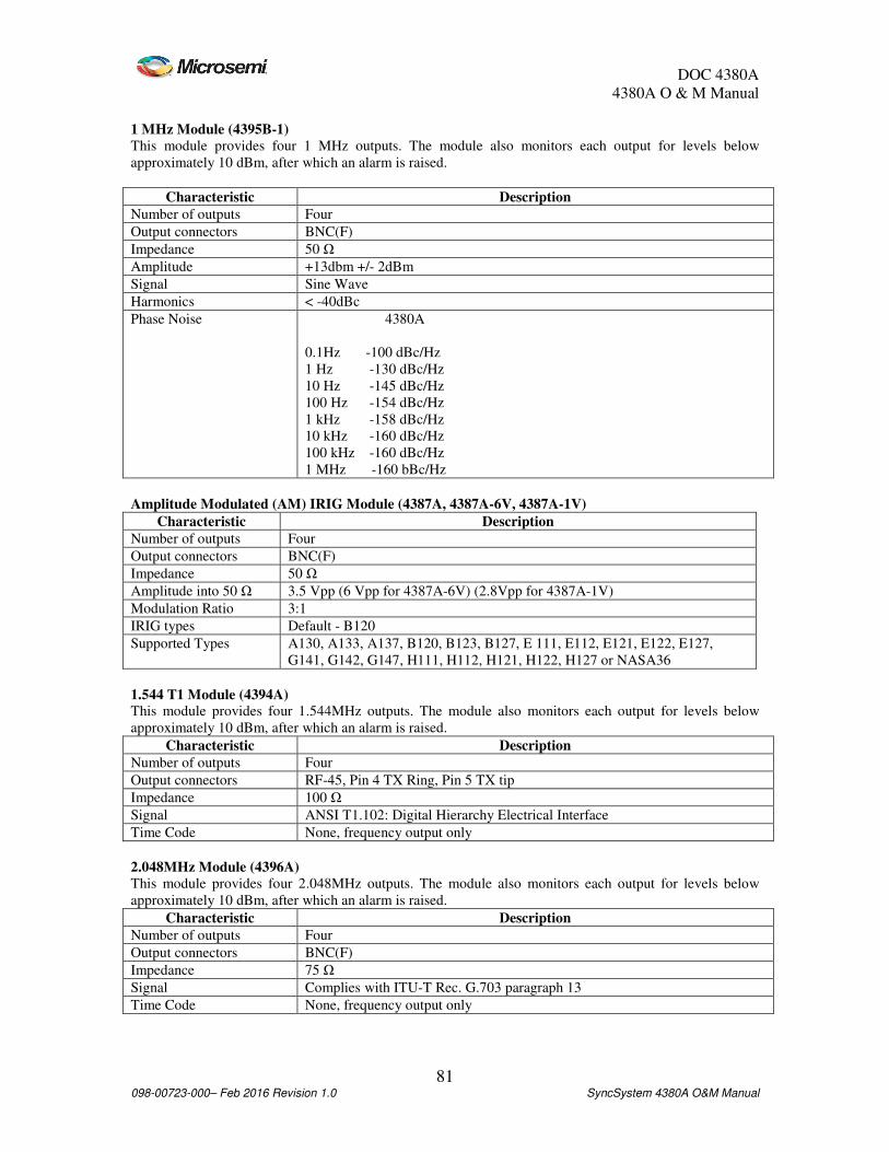
DOC 4380A
4380A O & M Manual
81 098-00723-000– Feb 2016 Revision 1.0 SyncSystem 4380A O&M Manual
1 MHz Module (4395B-1)
This module provides four 1 MHz outputs. The module also monitors each output for levels below
approximately 10 dBm, after which an alarm is raised.
Characteristic Description
Number of outputs Four
Output connectors BNC(F)
Impedance 50 Ω
Amplitude +13dbm +/- 2dBm
Signal Sine Wave
Harmonics < -40dBc
Phase Noise 4380A
0.1Hz -100 dBc/Hz
1 Hz -130 dBc/Hz
10 Hz -145 dBc/Hz
100 Hz -154 dBc/Hz
1 kHz -158 dBc/Hz
10 kHz -160 dBc/Hz
100 kHz -160 dBc/Hz
1 MHz -160 bBc/Hz
Amplitude Modulated (AM) IRIG Module (4387A, 4387A-6V, 4387A-1V)
Characteristic Description
Number of outputs Four
Output connectors BNC(F)
Impedance 50 Ω
Amplitude into 50 Ω 3.5 Vpp (6 Vpp for 4387A-6V) (2.8Vpp for 4387A-1V)
Modulation Ratio 3:1
IRIG types Default - B120
Supported Types A130, A133, A137, B120, B123, B127, E 111, E112, E121, E122, E127,
G141, G142, G147, H111, H112, H121, H122, H127 or NASA36
1.544 T1 Module (4394A) This module provides four 1.544MHz outputs. The module also monitors each output for levels below
approximately 10 dBm, after which an alarm is raised.
Characteristic Description
Number of outputs Four
Output connectors RF-45, Pin 4 TX Ring, Pin 5 TX tip
Impedance 100 Ω
Signal ANSI T1.102: Digital Hierarchy Electrical Interface
Time Code None, frequency output only
2.048MHz Module (4396A)
This module provides four 2.048MHz outputs. The module also monitors each output for levels below
approximately 10 dBm, after which an alarm is raised.
Characteristic Description
Number of outputs Four
Output connectors BNC(F)
Impedance 75 Ω
Signal Complies with ITU-T Rec. G.703 paragraph 13
Time Code None, frequency output only
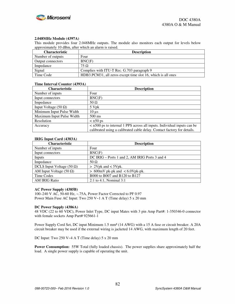
DOC 4380A
4380A O & M Manual
82 098-00723-000– Feb 2016 Revision 1.0 SyncSystem 4380A O&M Manual
2.048MHz Module (4397A)
This module provides four 2.048MHz outputs. The module also monitors each output for levels below
approximately 10 dBm, after which an alarm is raised.
Characteristic Description
Number of outputs Four
Output connectors BNC(F)
Impedance 75 Ω
Signal Complies with ITU-T Rec. G.703 paragraph 9
Time Code HDB3.PCM31, all zeros except time slot 16, which is all ones
Time Interval Counter (4393A)
Characteristic Description
Number of inputs Four
Input connectors BNC(F)
Impedance 50 Ω
Input Voltage (50 Ω) 5 Vpk
Minimum Input Pulse Width 10 µs
Maximum Input Pulse Width 500 ms
Resolution < ±50 ps
Accuracy < ±500 ps to internal 1 PPS across all inputs. Individual inputs can be
calibrated using a calibrated cable delay. Contact factory for details.
IRIG Input Card (4383A)
Characteristic Description
Number of inputs Four
Input connectors BNC(F)
Inputs DC IRIG – Ports 1 and 2, AM IRIG Ports 3 and 4
Impedance 50 Ω
DCLS Input Voltage (50 Ω) > 2Vpk and < 5Vpk.
AM Input Voltage (50 Ω) > 600mV pk-pk and < 6.0Vpk-pk.
Time Codes B000 to B007 and B120 to B127
AM IRIG Ratio 2:1 to 4:1, Nominal 3:1
AC Power Supply (4385B)
100–240 V AC, 50-60 Hz, ~.75A, Power Factor Corrected to PF 0.97
Power Main Fuse AC Input: Two 250 V~1 A T (Time delay) 5 x 20 mm
DC Power Supply (4386A)
48 VDC (22 to 60 VDC), Power Inlet Type, DC input Mates with 3 pin Amp Part#: 1-350346-0 connector
with female sockets Amp Part# 925661-1
Power Supply Cord Set, DC input Minimum 1.5 mm² (14 AWG) with a 15 A fuse or circuit breaker. A 20A
circuit breaker may be used if the external wiring is jacketed 14 AWG, with maximum length of 20 feet.
DC Input: Two 250 V~4 A T (Time delay) 5 x 20 mm
Power Consumption: 55W Total (fully loaded chassis). The power supplies share approximately half the
load. A single power supply is capable of operating the unit.

DOC 4380A
4380A O & M Manual
83 098-00723-000– Feb 2016 Revision 1.0 SyncSystem 4380A O&M Manual
Appendix B CE Declaration