OPERATION MANUAL - jdzj.com
124
F741-C WEIGHING INDICATOR 20 Mar. 2008 Rev. 1.00 OPERATION MANUAL
Transcript of OPERATION MANUAL - jdzj.com

F741-C WEIGHING INDICATOR
20 Mar. 2008Rev. 1.00
OPERATION MANUAL

Introduction
IntroductionWe appreciate your kind purchase of F741-C Weighing Controller.The F741-C is a weighing indicator
for load cell(s). It is best suited for checker and hopper scale measurements.To take full advantage of
high performance of F741-C, thoroughly read this operating manual first before use and understand the
explanations contained herein for correct operating procedures.Also, carefully store this instruction
manual so that it can be referred to at any time.
Safety Precautions
Installation, maintenance and inspection of the F741-C should be performed by personnel having
technical knowledge of electricity.
In order to have an F741-C Weighing Controller used safely, notes I would like you to surely follow
divide into and , and are indicated by the following documents. Notes
indicated here are the serious contents related safely. Please use after understanding the contents
well.Please use after understanding the contents well.
Be sure to read for safety.
WARNING CAUTION
WARNINGMisuse may cause the risk of death or serious
injury to persons.
CAUTIONMisuse may cause the risk of injury to persons
or damage to property.
I
Safety Precautions
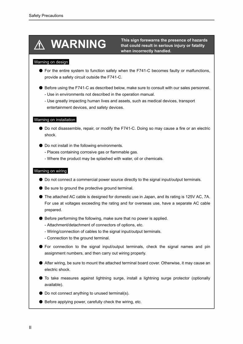
WARNING
● For the entire system to function safely when the F741-C becomes faulty or malfunctions,provide a safety circuit outside the F741-C.
● Before using the F741-C as described below, make sure to consult with our sales personnel.- Use in environments not described in the operation manual.- Use greatly impacting human lives and assets, such as medical devices, transport entertainment devices, and safety devices.
● Do not disassemble, repair, or modify the F741-C. Doing so may cause a fire or an electricshock.
● Do not install in the following environments.- Places containing corrosive gas or flammable gas.- Where the product may be splashed with water, oil or chemicals.
● Do not connect a commercial power source directly to the signal input/output terminals.
● Be sure to ground the protective ground terminal.
● The attached AC cable is designed for domestic use in Japan, and its rating is 125V AC, 7A.For use at voltages exceeding the rating and for overseas use, have a separate AC cableprepared.
● Before performing the following, make sure that no power is applied.- Attachment/detachment of connectors of options, etc.- Wiring/connection of cables to the signal input/output terminals.- Connection to the ground terminal.
● For connection to the signal input/output terminals, check the signal names and pinassignment numbers, and then carry out wiring properly.
● After wiring, be sure to mount the attached terminal board cover. Otherwise, it may cause anelectric shock.
● To take measures against lightning surge, install a lightning surge protector (optionallyavailable).
● Do not connect anything to unused terminal(s).
● Before applying power, carefully check the wiring, etc.
This sign forewarns the presence of hazards that could result in serious injury or fatality when incorrectly handled.
Warning on design
Warning on installation
Warning on wiring
II

Safety Precautions
● Use a power supply voltage and load within the specified and rated ranges.
● Do not damage the power cord. Doing so may cause fire or electric shocks.
● Do not touch any signal input/output terminal while applying power. Doing so may causeelectric shocks or malfunctions.
● If the cover of the main body is opened, it may cause an electric shock internally. Even if thepower is off, the internal capacitor is charged. Contact us for internal inspection or repair.
● In the case of smoke, an abnormal smell or strange sound, immediately turn off the power,and disconnect the power cable.
CAUTION
● Use the F741-C as it is incorporated in a control panel, etc.
● Do not install in the following environments.- Where the temperature/humidity exceeds the range of the specifications.- Where the temperature changes remarkably or there is a danger of freezing or condensing.- Outdoors, or where the altitude exceeds 2000m.- Places exposed to direct sunlight- Dusty places- Places containing large quantities of salt or iron powder.- Where the main body is directly affected by vibrations or shocks.
● Take adequate shielding measures when using at the following locations.- Near a power line.- Where a strong electric field or magnetic field is formed.- Where static electricity, relay noise or the like is generated.
● Install the F741-C as far away from devices generating high frequency, high voltage, largecurrent, surge, etc., as possible. Also, carry out wiring separately from their power lines. Donot carry out parallel wiring and common wiring.
● Do not use it, broken down.
● Tighten the screws for the signal input/output terminals at the specified torque.
If they are loose, shorts, fire or malfunctions may occur.Tightening torque: 0.5N•m
● For sensors, external inputs/outputs and options, use shielded cables.
WARNING
This sign forewarns the presence of hazards that could result in serious injury or fatality when incorrectly handled.
Warning during startup and maintenance
This sign forewarns the presence of hazards that could result in personnel injury or property damage when incorrectly handled.
Caution on installation
Caution on wiring
III

RoHS-compliant product
RoHS-compliant product
The parts and attachments (including the instruction manual, packaging box, etc.) used for this unit arecompliant with the RoHS Directive restricting the use of hazardous substances with regard to adverseeffects on the environment and human body.
What is RoHS?
It is an abbreviation for Restriction on Hazardous Substances, which is implemented by the EuropeanUnion (EU). The Directive restricts the use of six specific substances in electric and electronicequipment handled within EU borders. The six substances are lead, mercury, cadmium, hexavalentchromium, PBB (polybrominated biphenyls), and PBDE (polybrominated diphenyl ethers).
● For turning on/off the power, be sure to keep intervals of 5 seconds or more.
● After power-on, make sure to warm up the F741-C for 30 minutes or more before use.
● If the F741-C is not used by the specified method, its protective performance may beimpaired.
● Maintenance
- When performing maintenance, disconnect the power.- Do not wipe with a wet rag, or with benzine, thinner, alcohol, etc. Doing so may cause
discoloration or deformation of the F741-C. In the case of heavy contamination, wipe offthe contamination with a cloth after dipping it into a diluted neutral detergent and wringingit well, and then wipe with a soft, dry cloth.
● When the F741-C is shipped, spacers made of corrugated cardboard are used as
cushioning materials.Though it is factory-designed so that shocks can sufficiently be absorbed, breakage mayresult if shocks are applied when the spacers are reused for transportation. If you send theF741-C to us for repair, etc., take adequate measures against shocks by using polyurethanematerials, etc., separately.
● If you dispose of the product, handle it as industrial waste.
CAUTION This sign forewarns the presence of hazards that could result in personnel injury or property damage when incorrectly handled.
Caution during startup and maintenance
Caution during transportation
Caution during disposal
Please inquire of our sales person about the RoHS-compliance of the option.
IV
目次
目次
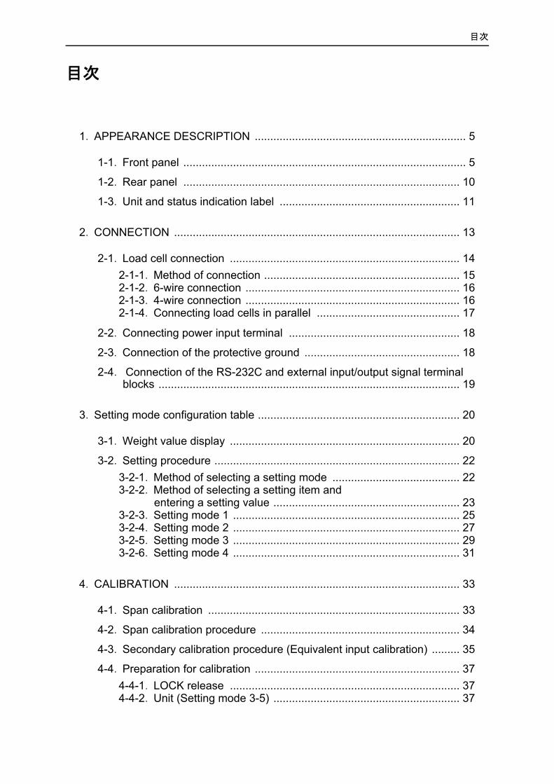
1. APPEARANCE DESCRIPTION .................................................................... 5
1-1. Front panel ........................................................................................... 5
1-2. Rear panel ......................................................................................... 10
1-3. Unit and status indication label .......................................................... 11
2. CONNECTION ............................................................................................ 13
2-1. Load cell connection .......................................................................... 142-1-1. Method of connection ............................................................... 152-1-2. 6-wire connection ..................................................................... 162-1-3. 4-wire connection ..................................................................... 162-1-4. Connecting load cells in parallel .............................................. 17
2-2. Connecting power input terminal ....................................................... 18
2-3. Connection of the protective ground .................................................. 18
2-4. Connection of the RS-232C and external input/output signal terminal blocks ................................................................................................. 19
3. Setting mode configuration table ................................................................. 20
3-1. Weight value display .......................................................................... 20
3-2. Setting procedure ............................................................................... 223-2-1. Method of selecting a setting mode ......................................... 223-2-2. Method of selecting a setting item and
entering a setting value ............................................................ 233-2-3. Setting mode 1 ......................................................................... 253-2-4. Setting mode 2 ......................................................................... 273-2-5. Setting mode 3 ......................................................................... 293-2-6. Setting mode 4 ......................................................................... 31
4. CALIBRATION ............................................................................................ 33
4-1. Span calibration ................................................................................. 33
4-2. Span calibration procedure ................................................................ 34
4-3. Secondary calibration procedure (Equivalent input calibration) ......... 35
4-4. Preparation for calibration .................................................................. 374-4-1. LOCK release .......................................................................... 374-4-2. Unit (Setting mode 3-5) ............................................................ 37

目次
4-4-3. Decimal place (Setting mode 3-5) ............................................ 384-4-4. Capacity (Setting mode 3-2) .................................................... 384-4-5. Minimum scale division (Setting mode 3-3) ............................. 384-4-6. Balance weight value (Setting mode 3-1) ................................ 384-4-7. Gravitational acceleration (Setting mode 3-6) .......................... 394-4-8. 1/4 Scale division (Setting mode 3-5) ...................................... 40
4-5. Zero calibration (Setting mode 3-8) ................................................... 41
4-6. Span calibration (Setting mode 3-9) .................................................. 43
4-7. Secondary calibration (Equivalent input calibration)(Setting mode 3-7) ................................ 44
4-8. FUNCTION SETTINGS .................................................................... 444-8-1. Display frequency (Setting mode 3-5) ...................................... 44
4-9. Digital filter (Setting mode 2-2) .......................................................... 45
4-10. Filter in stable condition (Setting mode 2-8) .................................... 45
4-11. Motion detection(MD) (Setting mode 2-3,2-4,2-8) ........................... 45
4-12. Zero tracking (ZT) ............................................................................ 48
4-13. Digital zero (DZ) ............................................................................... 48
4-14. Digital zero clear .............................................................................. 49
4-15. Zero regulation value (Setting mode 3-4) ........................................ 49
4-16. Gross weight display/net weight display .......................................... 49
4-17. One-touch tare subtraction (TARE) ................................................. 50
4-18. One-touch tare subtraction reset ..................................................... 51
4-19. Digital tare subtraction ..................................................................... 51
4-20. Tare weight display .......................................................................... 52
4-21. Validation of function keys (Setting mode 2-9) ................................ 52
5. WEIGHING SETTING AND OPERATION .................................................. 53
5-1. Comparison mode (Setting mode 2-7 Weighing function 1) ............. 53
5-2. Near zero comparison ........................................................................ 53
5-3. Upper/Lower limit comparison mode ................................................. 545-3-1. Upper/Lower limit comparison mode ....................................... 54
5-4. Over/Under comparison mode ........................................................... 565-4-1. Over/Under comparison mode ................................................. 56
5-5. Discharging control mode .................................................................. 595-5-1. Discharging control .................................................................. 59
6. SYSTEM MODE .......................................................................................... 63

目次
6-1. LOCK(soft) ......................................................................................... 63
6-2. PASSWORD ...................................................................................... 63
6-3. Self-check .......................................................................................... 63
7. EXTERNAL INPUT/OUTPUT SIGNALS (CONTROL CONNECTOR) ........................................................................ 64
7-1. Control connector-pin assignment ..................................................... 64
7-2. Equivalent circuit (Input) .................................................................... 64
7-3. Equivalent circuit (Output) .................................................................. 65
7-4. External input signal ........................................................................... 657-4-1. Tare (Tare ON) < Edge input > ............................................. 65
7-5. External output signal ........................................................................ 667-5-1. When comparison mode 0 (Upper/Lower limit comparison mode)
is set ......................................................................................... 667-5-2. When comparison mode 1 (Over/Under comparison mode)
is set ........................................................................................ 667-5-3. When comparison mode 2 (Discharging control mode)
is set ......................................................................................... 66
8. INTERFACE ................................................................................................ 67
8-1. RS-232C Interface[232] .................................................................. 678-1-1. Communication specifications ................................................. 678-1-2. Cable ........................................................................................ 678-1-3. Setting values for RS-232C ..................................................... 688-1-4. Communication mode .............................................................. 698-1-5. Transmission on format ........................................................... 718-1-6. Communication format ............................................................. 728-1-7. Setting value communication format ........................................ 768-1-8. About the auto print function .................................................... 77
8-2. D/A Converter[DAC] ....................................................................... 798-2-1. Name of each part ................................................................... 798-2-2. Specifications ........................................................................... 808-2-3. Method of adjusting the d/a zero and gain ............................... 818-2-4. About D/A resolution ................................................................ 82
8-3. Profibus interface[PRF] .................................................................. 838-3-1. Specifications ........................................................................... 838-3-2. Dimensions .............................................................................. 838-3-3. Name of each part ................................................................... 848-3-4. F741-C settings ....................................................................... 858-3-5. Address map ............................................................................ 868-3-6. Read, write, and command procedures ................................... 94

目次
9. OVER SCALE & ERROR ............................................................................ 97
9-1. Over scale .......................................................................................... 97
9-2. Calibration error ................................................................................. 97
10. TROUBLE SHOOTING ............................................................................. 98
11. PRECAUTIONS IN SETTING AND COMMAND EXECUTION .............. 103
12. BLOCK DIAGRAM .................................................................................. 104
13. DIMENSIONS ......................................................................................... 105
13-1. Standard equipment ....................................................................... 105
13-2. Dimensions (When the dac option is equipped) ............................ 106
13-3. Dimensions (When the prf option is equipped) .............................. 107
14. MOUNTING ON A PANEL ...................................................................... 108
15. SPECIFICATIONS .................................................................................. 109
15-1. Analog section ............................................................................... 109
15-2. Display section ............................................................................... 109
15-3. Setting section ............................................................................... 110
15-4. External input/output ...................................................................... 111
15-5. Interface ......................................................................................... 111
15-6. General performance ..................................................................... 113
15-7. Attachment ..................................................................................... 114
16. THE LIST OF INITIAL SETTING VALUE ................................................ 115
16-1. Setting mode 1 ............................................................................... 115
16-2. Setting mode 2 ............................................................................... 116
16-3. Setting mode 3 ............................................................................... 117
16-4. Setting mode 4 ............................................................................... 117
17. STATEMENT OF CONFORMATION TO EC DIRECTIVES ................... 118
17-1. Connection of lightning serge protect ............................................ 119
1.APPEARANCE DESCRIPTION
1.APPEARANCE DESCRIPTION
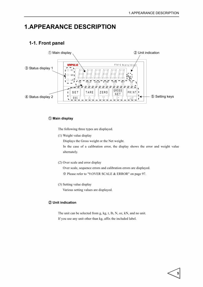
1-1. Front panel
① Main display
The following three types are displayed.
(1) Weight value displayDisplays the Gross weight or the Net weight. In the case of a calibration error, the display shows the error and weight value alternately.
(2) Over scale and error displayOver scale, sequence errors and calibration errors are displayed.
※ Please refer to "9.OVER SCALE & ERROR" on page 97.
(3) Setting value displayVarious setting values are displayed.
② Unit indication
The unit can be selected from g, kg, t, lb, N, oz, kN, and no unit. If you use any unit other than kg, affix the included label.
④ Status display 2
① Main display
⑤ Setting keys
② Unit indication
③ Status display 1
5

1.APPEARANCE DESCRIPTION
③ Status display1
The contents of the display differ according to the setting state of the comparison mode.
● When comparison mode 0 (upper/lower limit comparison mode) is set
HI Lights when the weight value > upper limit setting value. " "
GO Lights when
the lower limit setting value ≦ weight value ≦ upper limit setting value.
" "
LO Lights when the weight value < lower limit setting value. " "
● When comparison mode 1 (over/under comparison mode) is set
HI Lights when the weight value > (target value + over). " "
GO Lights when (target value - under) ≦ weight value ≦ (target value + over).
" "
LO Lights when the weight value < (target value - under). " "
● When comparison mode 2 (discharging control mode) is set
COMPL Lights while the COMPLETE signal is output. " "
SP2 Lights when the weight value ≧ (final - compensation). " "
SP1 Lights when the weight value ≧ (final - Set point 1). " "
* If Set point 1 = 0, SP1 is always unlit.
※ For the discharging control mode, affix the attached "COMPL/SP2/SP1" label to "HI/GO/LO."
④ Status display2
NZ Lights when the weight value ≦ near zero setting value. " "
※ The type of weight value is determined by near zero comparison mode (weighing function 1 in setting mode 2-7).
HOLD Lights while the weight value is held. " "
※ However, there is a need to set the auto print mode to 2 (auto print ON, weight value hold).
ZALM Flashes when the total amount of digital zero exceeds the DZ regulation value
in digital zero or zero tracking operation. " "
● HI
● GO
● LO
● HI
● GO
● LO
● COMPL
● SP2
● SP1
NZ●
HOLD●
ZALM●
6

1.APPEARANCE DESCRIPTION
STAB Lights when the weight value is stable. " "
※ For the definition of stability, see
"4-11.Motion detection(MD) (Setting mode 2-3,2-4,2-8)" on page 45.
TARE Lights when Tare subtraction is performed. " "
NET Lights when net weight is displayed. " "
Goes out when gross weight is displayed. " "
CZ • Lights at a true zero point (0 ± 1/4 scale division). " "
(When the 1/4 scale division display is OFF under display selection in setting
mode 3-5.)
• Lights at a true zero point (0 ± 1/4 scale division), and at the central point of
the scale interval of the indicated value {indicated value ± (1/4 × min. scale
division)}. " "
(When the 1/4 scale division display is ON under display selection in setting
mode 3-5.)
⑤ Setting keys
< SET >
If this key is pressed when a weight value is displayed, it switches to setting mode display. There are four setting modes : 1 to 4, which switches each time
the key is pressed.
< ESC >
If this key is pressed while a setting mode is displayed or a setting item is displayed, weight value display is brought back.
STAB●
TARE●
NET●
NET○
CZ●
CZ●
In this operation manual, the indications of the status display are shown as
"(lights/lit) ," "(goes out/unlit) ," and "(flashes/flashing) ". ● ○ ●
SETESC
GROSSNET
7

1.APPEARANCE DESCRIPTION
< TARE >
If this key is pressed, tare subtraction is immediately performed, and the net
weight is zeroed. At the same time, " " lights.
※ Clear the zero alarm by pressing the key while pressing the
key.
< ▲ >This key functions to switch to setting item display while a setting mode is displayed, and to change the selected item number while a setting item is displayed. Also, while an item is changed, it functions to increment the numerical value of the selected digit by one.
< ZERO >
If this key is pressed, the gross weight is immediately zeroed. If this operation is performed in an area exceeding the DZ regulation value, the DZ regulation value is subtracted from the gross weight, and a zero alarm
results. At the same time, " " flashes.
※ Clear the zero alarm by pressing the key while pressing the
key.
< ▼ >This key functions to switch to setting item display while a setting mode is displayed, and to change the selected item number while a setting item is displayed. Also, while an item is changed, it functions to decrement the numerical value of the selected digit by one.
< GROSS/NET >
If this key is pressed when a weight value is displayed, it switches immediately between gross weight and net weight.
If this key is pressed when gross weight is displayed( " " is unlit), it
switches to net weight display, and if this key is pressed when net weight is
displayed ( " " is lit) , it switches to gross weight.
TARE
TARE●
PRINT ZERO
ZERO
ZALM●
PRINT ZERO
GROSSNET
NET○
NET●
8

1.APPEARANCE DESCRIPTION
< >
This key functions to increment the selected setting mode by one while a setting mode is displayed. While an item is changed, it functions to move over digits.
< PRINT >
By pressing this key, the RS-232C format can be sent.
※ To send the RS-232C format, there is a need to make the following settingsin advance.
• Set the auto print mode (weighing function 1 in setting mode 2-7) to 0 (auto print OFF).
• Set the communication mode (RS-232C I/F setting in setting mode 4-1) to any of 4 to 6.
< >
This key functions to start item change while a setting item is displayed, and it functions to determine the setting item while an item is changed.
▲
The functioning of TARE, ZERO, and GROSS/NET can be disabled by the setting of "function key invalid" (setting mode 2-9).
9

1.APPEARANCE DESCRIPTION
1-2. Rear panel
① AC power input terminal board
Connect AC power code. The input voltage is 100V ~ 240V AC(+10% , -15%).
The frequency is 50/60Hz.
② Protective ground
This is a protective ground terminal board. Be sure to ground the protective ground
terminal to prevent electric shocks and failures due to static electricity. (The frame and
the protective ground terminal are conducted.)
③ LOCK switch
LOCK switch for avoiding changes of setting value, it prohibits to change setting value
while the switch is ON.
④ RS-232C terminal block
RS-232C connector for receiving and transmitting weight data and status information.
⑤ External input/output signal terminal block
This is a terminal block to input external signals and output external signals.The Input/
Output circuit and internal circuit are photocoupler-insulated electrically.
※ For use in discharging control mode, affix the attached "COMPL/SP2/SP1" label to
the "HI/GO/LO" part.
TXD
RX
DS
G
CO
M HI
GO LO
TAR
E
AC IN
F.G.
L
N
LOCKON OFF
SER.No.
MADE IN JAPAN
LOADCELL4321 5 6 7
TXD
RX
DS
G
CO
M HI
GO LO
TAR
E
AC IN
F.G.
L
N
LOCKON OFF
SER.No.
MADE IN JAPAN
LOADCELL4321 5 6 7
① AC power input terminal board
⑤ External input/output signal terminal block
⑥ Load cell input terminal board
⑦ Option space
③ LOCK switch
④ RS-232C terminal block
② Protective ground
10

1.APPEARANCE DESCRIPTION
⑥ Load cell input terminal board
This is a terminal board to connect load cell(s).
The applicable terminal board is Osada-manufactured ETB42-07P.
⑦ Option space
One of the following options can be mounted.
・D/A converter (DAC)
・PROFIBUS interface (PRF)
1-3. Unit and status indication label
The F741-C includes a unit and status indication label.
The label consists of the following three parts : ① to ③ . Affix them to the specified
places from (a) to (c) according to application before use.
① Unit label
If you use any unit other than kg for indicated values, select a corresponding unit label,
and affix it to the front panel (a).
If you use kg, no label needs to be affixed.
② Status indication label (for front panel)
If you use discharging control mode, affix it to the front panel (b).
If you use upper/lower limit comparison mode or over/under comparison mode, there is
no need to affix it.
① Unit label
③ Status indication label② Status indication label (for front panel) (for rear panel)
11

1.APPEARANCE DESCRIPTION
③ Status indication label (for rear panel)
If you use discharging control mode, affix it to the rear panel (c).
If you use upper/lower limit comparison mode or over/under comparison mode, there is
no need to affix it.
TXD
RX
DS
G
CO
M HI
GO LO
TAR
E
AC IN
F.G.
L
N
LOCKON OFF
SER.No.
MADE IN JAPAN
LOADCELL4321 5 6 7
(a)
(b)
(c)Front Panel Rear Panel
12

2.CONNECTION
2. CONNECTION
Precautions about connection to the signal input/output terminal board are given
below.The precautions described here are important for safety.
Please properly understand the descriptions before connection.
WARNING● Do not connect a commercial power source directly to the signal input/output
terminals.
● Connect to the signal input/output terminals with no power applied because it may cause an electric shock.
● For connection to the signal input/output terminals, check the signal names and pin assignment numbers, and then carry out wiring properly.
● The F741-C can be used only in category II specified by EN61010.The
overvoltage applied to the signal input/output terminals should not exceed the
value defined in category II.
● After wiring, be sure to mount the attached terminal board cover. Otherwise, it may cause an electric shock.
● Before applying power, carefully check the wiring, etc.
● Do not touch any signal input/output terminal while applying power. Doing so
may cause electric shocks or malfunctions.
● The F741-C conforms to the EMC Directive as an industrial environment
product (class A). If it is used in a housing environment, interference may be
caused. In that case, take appropriate measures.
CAUTION● Tighten the terminal screws at the specified torque.
If they are loose, shorts, fire or malfunctions may occur. Tightening torque: 0.5N•m
● Use shielded cables.
13

2.CONNECTION
2-1. Load cell connection
The voltage application of F741-C is 10V, and the maximum current is 120mA, to which
up to four 350Ω load cells can be connected in parallel.
Load cell terminal board pin assignments
Pin No. Signal (6-wire) Signal (4-wire)
1 + SIG + SIG
2 - SIG - SIG
3 + EXC + EXC
(Connect 3 to 4)4 + S
5 - EXC - EXC
(Connect 5 to 6)6 - S
7 SHIELD SHIELD
TXD
RX
DS
G
CO
M HI
GO LO
TAR
E
AC IN
F.G.
L
N
LOCKON OFF
SER.No.
MADE IN JAPAN
LOADCELL4321 5 6 7
Load cell terminal board
14

2.CONNECTION
2-1-1. Method of connection
1)Peel the sheath of the wire to be connected 5mm.
2)Twist the end to such an extent that it will not become loose.
3)Remove the terminal board from the F741-C body with a strong pull.
4)Loosen the screw with a screwdriver to open the hole. A Phillips screwdriver with a shaft diameter of 3 ~ 3.5mm #1 is recommendable (precision screwdriver, etc.).
5)Insert the wire into the hole so as not to loosen the end.
6)Tighten the screw with the screwdriver.
7)Lightly pull the wire to check that it is clamped securely.
※ Connectable wires are 0.21 ~ 3.31mm2 (AWG12 ~ 24). Recommendable tightening torque is 0.5Nm.
8)Insert the wire-connected plug into the F741-C body, and tighten the screws (two).
5mm
Turn
Hole
counterclockwise.
Turn clockwise.
Turn clockwise.
Screws(two)
When mounting the terminal board to the F741-C
body, check its vertical orientation.
(See the illustration on the right-hand side.)
RequestInsertion side
UP
DOWN
15
2.CONNECTION
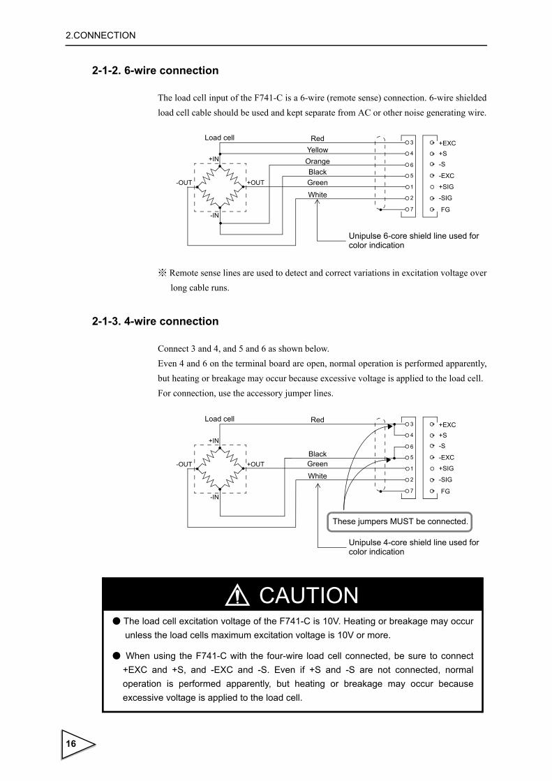
2-1-2. 6-wire connection
The load cell input of the F741-C is a 6-wire (remote sense) connection. 6-wire shielded load cell cable should be used and kept separate from AC or other noise generating wire.
※ Remote sense lines are used to detect and correct variations in excitation voltage over long cable runs.
2-1-3. 4-wire connection
Connect 3 and 4, and 5 and 6 as shown below. Even 4 and 6 on the terminal board are open, normal operation is performed apparently, but heating or breakage may occur because excessive voltage is applied to the load cell.For connection, use the accessory jumper lines.
+IN
-OUT
-IN
+EXC+S-S
-EXC
+SIG
-SIG
FG
+OUT
3
4
6
5
1
2
7
RedYellowOrangeBlackGreenWhite
Load cell
Unipulse 6-core shield line used for color indication
+IN
-OUT
-IN
+EXC+S-S
-EXC
+SIG
-SIG
FG
+OUT
3
4
6
5
1
2
7
Load cell Red
BlackGreenWhite
Unipulse 4-core shield line used for color indication
These jumpers MUST be connected.
CAUTION● The load cell excitation voltage of the F741-C is 10V. Heating or breakage may occur
unless the load cells maximum excitation voltage is 10V or more.
● When using the F741-C with the four-wire load cell connected, be sure to connect +EXC and +S, and -EXC and -S. Even if +S and -S are not connected, normal operation is performed apparently, but heating or breakage may occur because excessive voltage is applied to the load cell.
16
2.CONNECTION
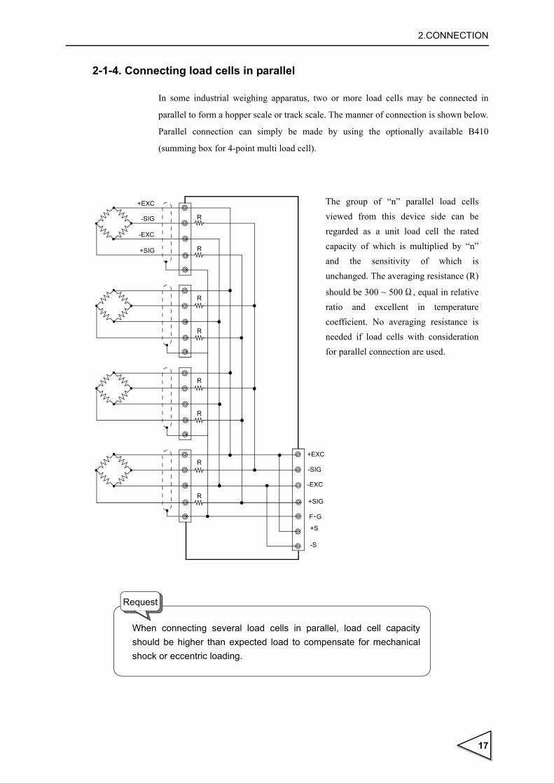
2-1-4. Connecting load cells in parallel
In some industrial weighing apparatus, two or more load cells may be connected in
parallel to form a hopper scale or track scale. The manner of connection is shown below.
Parallel connection can simply be made by using the optionally available B410
(summing box for 4-point multi load cell).
R
R
R
R
R
R
+EXC
-SIG
+SIG
-EXC
+EXC
-SIG
-EXC
+SIG
F・G
+S
-S
The group of “n” parallel load cells viewed from this device side can be regarded as a unit load cell the rated capacity of which is multiplied by “n” and the sensitivity of which is unchanged. The averaging resistance (R)
should be 300 ~ 500Ω, equal in relative ratio and excellent in temperature coefficient. No averaging resistance is needed if load cells with consideration for parallel connection are used.
When connecting several load cells in parallel, load cell capacity should be higher than expected load to compensate for mechanical shock or eccentric loading.
R
R
Request
17

2.CONNECTION
2-2. Connecting power input terminal
Connect the AC power cord. The input voltage is 100V to 240V AC. The frequency is 50/60Hz.
2-3. Connection of the protective ground
The grounding terminal is for prevention of electric shocks and failures caused by static
electricity.
Use an approx. 0.75mm2 thick wire, and be sure to ground.
board cover
Within 6mm
AC power cord
1) Make sure that no power is applied.
3) Remove the three screws(M3) at the lower left of the terminal board, align the crimp contacts with the screw holes, and then tighten the screws.
Frame ground
4) Mount the terminal board cover.
2) Remove the terminal board cover.
WARNING● Connect with no power applied because it may cause an electric shock.
● The attached AC cable is designed for domestic use in Japan, and its rating is 125V AC, 7A. For use at voltages exceeding the rating and for overseas use, have a separate AC cable prepared.
● Since the F741-C has no power switch, install a breaker.
●Be sure to ground the protective ground terminal to prevent electric shocks and failures by static electricity. (The frame and protective ground terminal are conducted.) Do not use other screws than that attached to the main body .
● To take measures against lightning surge, install a lightning surge protector (optionally available).
18

2.CONNECTION
2-4. Connection of the RS-232C and external input/output signal terminal blocks
RS-232C and external insertion Output terminal stand are the cage clamping types.
As wiring materials, use shielded cables.
Connect to the cage clamp type terminal board by using the attached mini screwdriver.
1)Strip the casing 0.2in (6mm) on the cable to be connected.
Twist the bare wire to fit the terminal hole.
2)Insert the supplied screwdriver into the upper hole and lift upward.
3) Insert the twisted wires into the lower hole.
4)Pull the screwdriver out from the upper hole.
5)Make sure cable is clamped securely and does not come out with a slight tug.
5 ~ 6mm
・Cable can be from 24 ~ 14AWG (0.2 ~ 2.5mm2).
・ It is not necessary to solder the cable wires or to fix a solderless terminal.
・If several cables to be inserted to the same hole, twist those cable wires together and insert.
Request
19

3.Setting mode configuration table
3. Setting mode configuration table
3-1. Weight value display
GROSS
NET
GROSSNET
TARE
▲
ZERO
▼
Gross weight Net weight
Setting Mode1
Comparison mode0 Comparison mode1 Comparison mode2
Upper/Lower limit Over/Under Discharging
1.Upper limit
3.Hold time
4.Near zero
5.Tare setting
2.Lower limit
1.Target value
7.Tare dispiay
6.Tare setting
3.Under
4.Hold time
5.Near zero
2.Over
1.Final
9.Tare dispiay
8.Tare setting
7.Near Zero
6.Complete output time
3.Set point 1
4.Comparison Inhibit time
5.Judging time
2.Compensation
SET
ESC
● Indicates lighting.
● Indicates flashing.
◇ Weight value display ◇
◇ Setting mode display ◇
◇ Setting item display ◇
NZ HOLD ZALM STAB TARE NET CZ● ○ ○ ○ ○ ○ ○
6.Tare dispiay
NZ HOLD ZALM STAB TARE NET CZ● ○ ○ ○ ○ ○ ○
NZ HOLD ZALM STAB TARE NET CZ● ○ ○ ○ ○ ○ ○
NZ HOLD ZALM STAB TARE NET CZ● ○ ○ ○ ○ ○ ○
NZ HOLD ZALM STAB TARE NET CZ● ○ ○ ○ ○ ○ ○
NZ HOLD ZALM STAB TARE NET CZ● ○ ○ ○ ○ ○ ○
NZ HOLD ZALM STAB TARE NET CZ● ○ ○ ○ ○ ○ ○
NZ HOLD ZALM STAB TARE NET CZ● ○ ○ ○ ○ ○ ○
NZ HOLD ZALM STAB TARE NET CZ● ○ ○ ○ ○ ○ ○
NZ HOLD ZALM STAB TARE NET CZ● ○ ○ ○ ○ ○ ○
※ Determine the comparison mode by weighing function 1 (setting mode 2-7).
Setting Mode1
● HI
● COMPL
● SP2● GO
● LO ● SP1
● LO ● HI
comparison mode comparison mode control mode
20

3.Setting mode configuration table
21
GROSSNET
GROSS
NET
TARE
▲
ZERO
▼
TARE
▲
ZERO
▼
TARE
▲
ZERO
▼
Setting Mode4Setting Mode3Setting Mode2
1.Balance weight value
9.Span calibration
8.Zero calibration
7.Equivalent input calibration
6.Gravitational acceleration
3.Min. scale division
4.DZ regulation value
5.Display selection
2.Capacity
1.Password
9.Key invaid・LOCK
8.Weighing function 2
7.Weighing function 1
6.Zero tracking(Range)
3.Motion detection(Period)
4.Motion detection(Range)
5.Zero tracking(Period)
2.Digital filter
Back to Setting Mode 1.
NZ HOLD ZALM STAB TARE NET CZ● ● ○ ○ ○ ○ ○
NZ HOLD ZALM STAB TARE NET CZ● ● ○ ○ ○ ○ ○
NZ HOLD ZALM STAB TARE NET CZ● ● ○ ○ ○ ○ ○
NZ HOLD ZALM STAB TARE NET CZ● ● ○ ○ ○ ○ ○
NZ HOLD ZALM STAB TARE NET CZ● ● ○ ○ ○ ○ ○
NZ HOLD ZALM STAB TARE NET CZ● ● ○ ○ ○ ○ ○
NZ HOLD ZALM STAB TARE NET CZ● ● ○ ○ ○ ○ ○
NZ HOLD ZALM STAB TARE NET CZ● ● ○ ○ ○ ○ ○
NZ HOLD ZALM STAB TARE NET CZ● ● ○ ○ ○ ○ ○
NZ HOLD ZALM STAB TARE NET CZ● ● ○ ○ ○ ○ ○
NZ HOLD ZALM STAB TARE NET CZ● ● ● ○ ○ ○ ○
NZ HOLD ZALM STAB TARE NET CZ● ● ● ● ○ ○ ○
NZ HOLD ZALM STAB TARE NET CZ● ● ● ○ ○ ○ ○
NZ HOLD ZALM STAB TARE NET CZ● ● ● ○ ○ ○ ○
NZ HOLD ZALM STAB TARE NET CZ● ● ● ○ ○ ○ ○
NZ HOLD ZALM STAB TARE NET CZ● ● ● ○ ○ ○ ○
NZ HOLD ZALM STAB TARE NET CZ● ● ● ○ ○ ○ ○
NZ HOLD ZALM STAB TARE NET CZ● ● ● ○ ○ ○ ○
NZ HOLD ZALM STAB TARE NET CZ● ● ● ○ ○ ○ ○
NZ HOLD ZALM STAB TARE NET CZ● ● ● ○ ○ ○ ○
1.RS-232C I/F setting
7.Station No.
6.PROFIBUS baud rate setting
3.D/A zero output setting
4.D/A full scale setting
5.PROFIBUS I/F setting
2.D/A output mode
NZ HOLD ZALM STAB TARE NET CZ● ● ● ○ ○ ○ ○
NZ HOLD ZALM STAB TARE NET CZ● ● ● ● ○ ○ ○
NZ HOLD ZALM STAB TARE NET CZ● ● ● ● ○ ○ ○
NZ HOLD ZALM STAB TARE NET CZ● ● ● ● ○ ○ ○
NZ HOLD ZALM STAB TARE NET CZ● ● ● ● ○ ○ ○
NZ HOLD ZALM STAB TARE NET CZ● ● ● ● ○ ○ ○
NZ HOLD ZALM STAB TARE NET CZ● ● ● ● ○ ○ ○
NZ HOLD ZALM STAB TARE NET CZ● ● ● ● ○ ○ ○
Setting Mode2 Setting Mode3 Setting Mode4

3.Setting mode configuration table
3-2. Setting procedure
Change settings in the order of "setting mode selection" → "setting item selection" →
"setting value entry".
3-2-1. Method of selecting a setting mode
(Example) For selecting setting mode 3
1) Press the key when the weight value is displayed.
2) Press the key twice.
kg
Present weight value
The weight value is displayed. The mode number is not displayed.
SETESC
kg
Setting mode number
The display changes.
GROSSNET
kg
Setting mode number
The setting mode number changes.
If no operation is performed for 2 seconds or more while a setting
mode number is displayed, it switches to setting item display in the
specified mode.
Also, if the keyis pressed while a setting mode number is
displayed, weight value display is brought back.
SETESC
22

3.Setting mode configuration table
3-2-2. Method of selecting a setting item and entering a setting value
(Example 1) For setting the balance weight value to 50.00kg. (Setting by numerical input.)
※ Hereinafter, it is assumed that setting mode 3 has already been selected for the
operating procedure.
1) Select the setting item.
(Since the setting item number of the balance weight value is 1,press the key.)
2) Press the key.
3) Input the setting value. In this case, make it "0" by pressing the keyonce, and
move to one digit lower by pressing the key.
4) Set "5" by pressing the key five times.
5) After the correct setting value is input, press the key to enter the setting value.
ZERO
kg
Present setting valueSetting item number
The setting item number is displayed.
kg The highest digit of the setting
The flashing digit can be changed.Present setting value
Setting item number
value flashes.
ZERO
GROSSNET
kg Each time the key is pressed, GROSS
NET
Present setting valueSetting item number
the flashing digit moves to a lower order.
TARE
kg
Present setting valueSetting item number
kg
Present setting valueSetting item number
23

3.Setting mode configuration table
(Example 2) For setting the 1/4 scale division display to OFF . (Setting from choices.)
※ Hereinafter, it is assumed that setting mode 3 has already been selected for the operating procedure.
1) Select the setting item.
(Press the key five times when setting mode 3 is displayed.)
2) Press the key.
3) Make the lowest digit flash by pressing the key three times.
4) Select from choices. (Since the 1/4 scale division display should be turned OFF in this case, set "0" by
pressing the key once.)
5) Upon completion of entering the correct choice, confirm (determine) your entry by
pressing the key.
ZERO
kg
Present setting valueSetting item number
※ Selection of 1/4 scale division is in
The setting item number, andpresent setting value are displayed.
setting mode 3-5 (display selection).
kg
Present setting valueSetting item number
The highest digit of the setting value flashes.
GROSSNET
kg
1/4 scale division displaySetting item number
Display frequencyDecimal placeUnit
Each time the key is pressed, GROSS
NET
the flashing digit moves to a lower order.
ZERO
kg
1/4 scale division displaySetting item number
Setting value of 1/4 scale division display0 : OFF / 1 : ON
kg
Setting valueSetting item number
By pressing the key when the setting item number is displayed
(while changing a setting value after selecting an item), you can exit the item (weight value display is brought back.)
SETESC
24

3-2-3. Setting mode 1
1) Comparison mode 0 (Upper/Lower limit comparison mode )
In comparison mode 0, upper/lower limit comparison is performed.
・Upper limit
・Lower limit
・Hold time
・Near zero
・Tare setting
・Tare display
2) Comparison mode 1 (Over/Under Comparison Mode)
In comparison mode 1, over/under comparison is performed.
・Target value
・Over
(0 ~ 99999)
(0 ~ 99999)
(0.0 ~ 9.9)
(0 ~ 99999)
(0 ~ 99999)
(0 ~ 99999)※ Display only
(0 ~ 99999)
(0 ~ 9999)
25

・Under
・Hold time
・Near zero
・Tare setting
・Tare display
3) Comparison mode 2 (Discharging control mode)
In comparison mode 2, discharging control is performed.
・Final
・Compensation
・Set point 1
・Comparison Inhibit time
(0 ~ 9999)
(0.0 ~ 9.9)
(0 ~ 99999)
(0 ~ 99999)
(0 ~ 99999)※ Display only
(0 ~ 99999)
(0 ~ 9999)
(0 ~ 99999)
(0.00 ~ 9.99)
26

・Judging time
・Complete output time
・Near zero
・Tare setting
・Tare display
3-2-4. Setting mode 2
Setting mode 2 relates to internal functions.
・Password
・Digital filter
・Motion detection(Period)
(0.0 ~ 9.9)
(0.0 ~ 9.9)
(0 ~ 99999)
(0 ~ 99999)
(0 ~ 99999)※ Display only
(0 ~ 9999)※ For extension (unused)
(1 ~ 128)
(0.0 ~ 9.9)
27
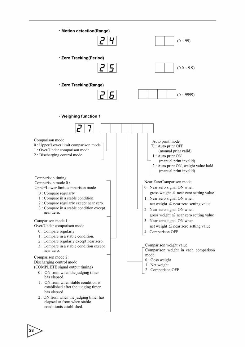
・Motion detection(Range)
・Zero Tracking(Period)
・Zero Tracking(Range)
・Weighing function 1
(0 ~ 99)
(0.0 ~ 9.9)
(0 ~ 9999)
Comparison mode 0 : Upper/Lower limit comparison mode1 : Over/Under comparison mode2 : Discharging control mode
Near ZeroComparison mode 0 : Near zero signal ON when
gross weight ≦ near zero setting value1 : Near zero signal ON when
net weight ≦ near zero setting value2 : Near zero signal ON when
gross weight ≦ near zero setting value3 : Near zero signal ON when
net weight ≦ near zero setting value4 : Comparison OFF
Comparison timingComparison mode 0 : Upper/Lower limit comparison mode 0 : Compare regularly 1 : Compare in a stable condition. 2 : Compare regularly except near zero. 3 : Compare in a stable condition except near zero.
Comparison weight valueComparison weight in each comparison mode0 : Goss weight1 : Net weight2 : Comparison OFF
Comparison mode 2: Discharging control mode (COMPLETE signal output timing) 0 : ON from when the judging timer has elapsed. 1 : ON from when stable condition is established after the judging timer has elapsed. 2 : ON from when the judging timer has elapsed or from when stable conditionis established.
Comparison mode 1 : Over/Under comparison mode 0 : Compare regularly 1 : Compare in a stable condition. 2 : Compare regularly except near zero. 3 : Compare in a stable condition except
near zero.
0 : Auto print OFF (manual print valid)
1 : Auto print ON (manual print invalid)
2 : Auto print ON, weight value hold (manual print invalid)
Auto print mode
28

・Weighing Function 2
・ Function key invalid
3-2-5. Setting mode 3
Setting mode 3 relates to calibration and display.
・Balance weight value
・Capacity
・Min. scale division
Filter in Stable Condition0 : Insert (64 times)1 : Not insert
Stable detection mode 0 : Stable mode (For discharging control)1 : Checker mode
Digital Tare Subtraction0 : Digital Tare Subtraction OFF1 : Digital Tare Subtraction ON
※ Undefined
【TARE】 key0 : Invaid1 : Valid
LOCK20 : OFF1 : ON
【ZERO】 key0 : Invaid1 : Valid
LOCK10 : OFF1 : ON
【GROSS/NET】 key0 : Invaid1 : Valid
(0 ~ 99999)
(0 ~ 99999)
(1 ~ 100)
29
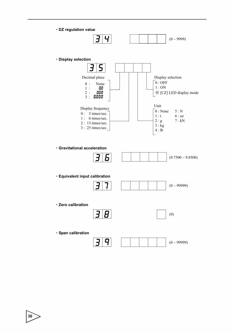
・DZ regulation value
・Display selection
・Gravitational acceleration
・Equivalent input calibration
・Zero calibration
・Span calibration
(0 ~ 9999)
Display frequency0 : 3 times/sec.1 : 6 times/sec.2 : 13 times/sec.3 : 25 times/sec.
Display selection0 : OFF1 : ON※ [CZ] LED display mode
Unit0 : None 5 : N 1 : t 6 : oz 2 : g 7 : kN 3 : kg 4 : lb
Decimal place
0 : None1 : 2 : 3 :
(9.7500 ~ 9.8500)
(0 ~ 99999)
(0)
(0 ~ 99999)
30

3-2-6. Setting mode 4
Setting mode 4 relates to interfaces.
・RS-232C I/F setting
・D/A output mode
・D/A zero output weight
・D/A full scale setting
Baud rate0 : 1200 bps1 : 2400 bps2 : 4800 bps3 : 9600 bps4 : 19200 bps5 : 38400 bps
Communication mode
Character length0 : 7bit1 : 8bit
Stop bit0 : 1bit1 : 2bit
Parity bit0 : None1 : Odd2 : Even
0 : Communication mode0/CR1 : Communication mode0/CR+LF2 : Communication mode13 : Communication mode24 : Communication mode3
5 : Communication mode46 : Communication mode57 : Communication mode6
Auto print and [PRINT] key operation are valid.
Output Mode 0 : Gross weight1 : Net weight
Test mode0 : Tied to the weight value1 : 4mA fixed output2 : 20mA fixed output
(0 ~ 99999)
(0 ~ 99999)
31

・PROFIBUS I/F setting
・PROFIBUS baud rate display
・Station No.
※ Undefined
DWORD (long word) mode0 : High order - low order word (Siemens PC, etc.)1 : Low order - high order word (Yokogawa PLC, etc.)
Display pattern Function
1 2 12 Mbps
6 6 Mbps
3 3 Mbps
1. 5 1.5 Mbps
5 0 0 500 kbps
1 8 7. 5 187.5 kbps
9 3. 7 5 93.75 kbps
1 9. 2 19.2 kbps
9. 6 9.6 kbps
- - - -Not linked or no PROFIBUS I/F
mounted
(0 ~ 125)
32

4.CALIBRATION
4. CALIBRATION
4-1. Span calibration
Calibration is performed for matching the F741-C to a load cell. For example, it is work
to adjust so that the F741-C accurately displays 100.00kg when an actual load (or
weight) of 100kg is applied to the load cell (balance section) of the weighing apparatus
to which the F741-C is connected. This operation is called Span Calibration.
Connect F741-C to the load cell.....
?
??
The display is incorrect.....
100kg
100kg
After calibration.....
The F741-C and load cellfunction as a weighing device.
○ H I
○ GO
○ LO○ ○ ○ ○ ○ ○ ○
kg
○ H I
○ GO
○ LO○ ○ ○ ○ ○ ○ ○
kg
PRINTGROSSNETZEROTARESET
ESC
PRINTGROSSNETZEROTARESET
ESC
33

4.CALIBRATION
4-2. Span calibration procedure
Follow the steps below to perform Span Calibration.
Release calibration inhibit LOCK by the switch OFF on the rear panel.
Release Setting Value LOCK which inhibits the calibration.
The displayed unit is set.
Register the position of decimal point.
Register the maximum capacity of the scale. If the registered value exceeds by 9 scale divisions, display shows over scale, " "
Register the minimum unit (scale division) of the scale.
Register the value of load (balance weight) for load cell.
Input the acceleration of the area in which calibration is performed.
Calibrate the initial zero point.
Place the load (balance weight) on the load cell and register the span value.
Disable changing setting value related to calibration.
Turn the calibration LOCK ON to prohibit the calibra- tion for avoiding false operation.
Release Calibration LOCK
Decimal Place
Min. Scale Division
Capacity
Balance Weight Value
Zero Calibration
Span Calibration
Calibration LOCK
LOCK Switch OFF
LOCK Switch ON
Unit
(Setting Mode 2-9)
(Setting Mode 3-9)
(Setting Mode 3-8)
(Setting Mode 3-1)
(Setting Mode 3-3)
(Setting Mode 3-2)
(Setting Mode 3-5)
(Setting Mode 3-5)
(Setting Mode 3-6)
Gravitational Acceleration
(Setting Mode 2-9)
34

4.CALIBRATION
4-3. Secondary calibration procedure (Equivalent input calibration)
Calibration procedure performed by entering the rated output value (mV/V) and rated capacity value of load cell without using real load. Secondary calibration function is provided for provisional calibration when the F741-C develops trouble or the calibration value is mistakenly changed. The secondary calibration is only a provisional method. Calibration with actual load must be done as soon as possible.
Release calibration inhibit LOCK by the switch OFF on the rear panel.
Release Setting Value LOCK which inhibits the calibration.
The displayed unit is set.
Register the position of decimal point.
Register the maximum capacity of the scale. If the registered value exceeds by 9 scale divisions,
display shows over scale, " " .
Register the minimum unit (scale division) of the scale.
Set the weight value corresponding to the output value to be entered in *1.
Input the acceleration of the area in which correction is performed.
Register the rated output value (mV/V) of load cell.
Calibrate the initial zero point.
Disable changing setting value related to calibration.
Turn the calibration LCOK ON to prohibit the calibra- tion for avoiding false operation.
Release Calibration LOCK
Decimal Place
Min. Scale Division
Capacity
Balance Weight Value
Equivalent input
Calibration LOCK
LOCK Switch OFF
LOCK Switch ON
Unit
(Setting Mode 2-9)
(Setting Mode 2-9)
(Setting Mode 3-8)
(Setting Mode 3-7)
(Setting Mode 3-1)
(Setting Mode 3-3)
(Setting Mode 3-2)
(Setting Mode 3-5)
(Setting Mode 3-5)
(Setting Mode 3-6)
Gravitational Acceleration
Zero Calibration
calibration*1
35

4.CALIBRATION
・Set the Balance Weight Value to the Capacity or less.
・For performing calibration at the rated value according to the specifications of the load cell, set the Capacity to the same value as the rated value of the load cell.
・When connecting several load cells in parallel, it is possible to occur some differences between input and output value due to voltage drop caused by connection or material of lines. In this case, register actual input value to perform accurate calibration.
・ If the area of calibration and the area of use are different, weight errors may occur due to a difference in gravitational acceleration. If you use units other than N and kN, input the acceleration of the area of use referring to the gravitational acceleration correction table on page 39. Use 9.8067(Initial value) when you use N or kN.
Request
36

4.CALIBRATION
4-4. Preparation for calibration
4-4-1. LOCK release
F741-C features a LOCK function for disabling changes in calibration and setting values.
The software LOCK is performed with the operation on the display; the hardware LOCK
is located on rear panel. Release both of locks when the calibration is performed.
Operation
1) LOCK OFF on the rear panel
2) Select setting mode 2-9 ( Function key invalid・LOCK).
3) Set LOCK2 to OFF.
LOCK is released through above procedure. After the calibration is finished, LOCK ON
to protect the calibration value.
4-4-2. Unit (Setting mode 3-5)
This is used in the RS-232C sending format or PROFIBUS I/F IN data.
Even if this setting is changed, it is not reflected in the display.
Select the unit from 0: none / 1: t / 2: g / 3: kg / 4: lb / 5: N / 6: oz / 7: kN.
TXD
RX
DS
G
CO
M HI
GO LO
TAR
E
AC IN
F.G.
L
N
LOCKON OFF
SER.No.
MADE IN JAPAN
LOADCELL4321 5 6 7
LOCKOFF
LOCK20 : OFF1 : ON
Function key invalid・LOCK
Concerning LOCK and setting values to be protected, refer to "16.THE LIST OF INITIAL SETTING VALUE" on page 115.
37

4.CALIBRATION
4-4-3. Decimal place (Setting mode 3-5)
Set the decimal point position common to weight-related displays, setting items, etc., by
this selection.
Select the decimal point position from 0: 0 / 1: 0.0 / 2: 0.00 / 3: 0.000.
4-4-4. Capacity (Setting mode 3-2)
Register the maximum capacity of the scale. If the registered value exceeds by 9 scale
divisions, display shows over scale, " " .(Input range / 0 ~ 99999)
4-4-5. Minimum scale division (Setting mode 3-3)
Register the minimum unit (scale division) of the scale.
(Input range / 1 ~ 100)
4-4-6. Balance weight value (Setting mode 3-1)
Register the value of load (balance weight) before the Span Calibration.
(Input range / 0 ~ 99999)
UnitDisplay selection0 : None 5 : N 1 : t 6 : oz 2 : g 7 : kN 3 : kg 4 : lb
Decimal place
Display selection
0 : None1 : 2 : 3 :
In the F741-C, the decimal place is all fixed except for weight-related descriptions. ※ It cannot be changed.
38

4.CALIBRATION
4-4-7. Gravitational acceleration (Setting mode 3-6)
If the calibration location and installation location of the balance are different, correct the weight errors resulting from an area-to-area difference in gravitational acceleration by this function. If the calibration location and installation location are in the same area, this setting is not needed. Find the regional acceleration of the area in which actual load calibration is performed from the following gravitational acceleration correction table, set the value of the acceleration, and then perform actual load calibration. Now, the difference in gravitational acceleration from the calibration location is corrected.
Gravitational acceleration
※ If the area of the calibration location is not in the table, set the gravitational
acceleration of the area closest in latitude.
However, the value in the table may be different from the actual value depending on
the longitude and altitude.
If accuracy is required, re-calibration in the area of use is recommended.
Area (G) Area (G) Area (G)
Amsterdam 9.8128m/s2 Hanoi 9.7870m/s2 Oslo 9.8191m/s2
Athens 9.7999m/s2 Havana 9.7883m/s2 Ottawa 9.8066m/s2
Auckland 9.7986m/s2 Helsinki 9.8193m/s2 Paris 9.8097m/s2
Bangkok 9.7832m/s2 Ho Chi Minh 9.7820m/s2 Phnom Penh 9.7824m/s2
Beijing 9.8155m/s2 Hong kong 9.7878m/s2 Rio de janeiro 9.7879m/s2
Berlin 9.8129m/s2 Kualalumpur 9.7805m/s2 Rome 9.8034m/s2
Birmingham 9.8127m/s2 Kuwait 9.7928m/s2 San Francisco 9.7994m/s2
Brussels 9.8115m/s2 Lisbon 9.8006m/s2 Seoul 9.7995m/s2
Buenos Aires 9.7970m/s2 London 9.8120m/s2 Shanghai 9.7946m/s2
Kolkata 9.7878m/s2 Los Angelse 9.7965m/s2 Singapore 9.7804m/s2
Capetown 9.7964m/s2 Madrid 9.8021m/s2 Stockholm 9.8186m/s2
Chicago 9.8030m/s2 Manila 9.7836m/s2 Sydney 9.7961m/s2
Copenhagen 9.8156m/s2 Melbourne 9.7995m/s2 Taipei 9.7896m/s2
Nikosia 9.7975m/s2 Mexico City 9.7860m/s2 Tokyo 9.7979m/s2
Djakarta 9.7809m/s2 Milan 9.8065m/s2 Vancouver,BC 9.8099m/s2
Frankfurt 9.8107m/s2 Mumbai 9.7856m/s2 Washinton DC 9.8007m/s2
Glasgow 9.8155m/s2 New Delhi 9.7922m/s2 Wellington 9.8028m/s2
Istanbul 9.8026m/s2 New York 9.8021m/s2 Zurich 9.8082m/s2
39

4.CALIBRATION
4-4-8. 1/4 Scale division (Setting mode 3-5)
It divides the minimum scale division into four (4) parts. The " " (center zero) lamp
turns on when the weight is between +1/4 division and -1/4 division.
1/4 scale division selects ON/OFF.
Operation1)Select setting mode 3-5(Display selection).
2)Select 1/4 scale division display ON/OFF.
CZ●
1/4 Scale division display0 : OFF1 : ON
Display selection
n n + 1
1/4 scale
Min. scale division
ON " " ON " " CZ●
CZ●
CZ●
(1scale divisio)
When the 1/4 scale division setting is OFF, " " lamp only works at the zero point.
CZ●
-1 1/4 scale01
ON " " CZ●
40

4.CALIBRATION
4-5. Zero calibration (Setting mode 3-8)
Register initial zero point.
・Verify there are no excess loads applied to load cell (or scale).
・Check that " " is ON.
(Correct calibration can not be completed if signal is unstable.)
Operation
1) Select setting mode 3-8(Zero calibration).
2)Register the Zero point.
3)When the weight value display becomes 0, Zero Calibration is completed.
If a calibration error is displayed, redo Zero Calibration corresponding to the following
error messages. (Please refer to"9.OVER SCALE & ERROR" on page 97)
・ " "
Do zero calibration again.
Initial dead load is above zero adjustment range.
Remove any excess load from load cell or scale. If is still displayed,
connect a resistor between +EXC and -SIG load cell connections. This should
shift the zero point.
STAB●
kg
Press the key twice.PRINT
In-zero-calibration display.
kg
Weight value
Setting item number
41

4.CALIBRATION
・ " "
Inditial dead load is negative.
Check that load cell is mounted in the correct direction; check that load is being
applied to the load cell in the correct direction; check that the +SIG and -SIG lines
are propely connected.
If still displayed, connect a resistor between -EXC and -SIG load
cell connections. This should shift the zero point. Do Zero Calibration again.
・This table is for a 350 Ω load cell.
・The temperature coefficient of the connected resistor directly influences the accuracy of the indicator. Use a resistance having a temperature coefficient of 50ppm/ ℃ or more (recommended value of about 5ppm to 10ppm / ℃ ).
Resistance StrainCalculated value Approx.value μ-STRAIN mV/V
875 KΩ
437 KΩ
291 KΩ
219 KΩ
175 KΩ
146 KΩ
125 KΩ
109 KΩ
97 KΩ
87.3 KΩ
79.4 KΩ
72.7 KΩ
67.1 KΩ
62.3 KΩ
58.2 KΩ
54.5 KΩ
51.3 KΩ
48.4 KΩ
45.9 KΩ
43.6 KΩ
41.5 KΩ
39.6 KΩ
37.9 KΩ
36.3 KΩ
34.8 KΩ
866 KΩ
442 KΩ
294 KΩ
221 KΩ
174 KΩ
147 KΩ
124 KΩ
110 KΩ
97.6 KΩ
86.6 KΩ
78.7 KΩ
73.2 KΩ
66.5 KΩ
61.9 KΩ
57.6 KΩ
54.9 KΩ
51.1 KΩ
48.7 KΩ
46.4 KΩ
43.2 KΩ
41.2 KΩ
39.2 KΩ
38.3 KΩ
36.5 KΩ
34.8 KΩ
200400600800
100012001400160018002000220024002600280030003200340036003800400042004400460048005000
0.10.20.30.40.50.60.70.80.91.01.11.21.31.41.51.61.71.81.92.02.12.22.32.42.5
42

4.CALIBRATION
4-6. Span calibration (Setting mode 3-9)
Span calibration means putting a load (test weight) on the load cell (or scale) and
calibrating so the F741-C indicates correct weight.
・Put the balance weight value which is set the balance weight value, on the load cell (or scale). (Calibrating with more than 50% of the Capacity is favorable in respect of linearity.)
・Verify there are no excess loads applied to load cell (or scale).
・Check that " " is on. (Correct calibration can not be completed if signal is unstable.)
Operation
1)Select setting mode 3-9(Span calibration).
2)Perform span calibration.
3)When the weight value display becomes equal to the Balance Weight Value, Span
Calibration is completed.
※ If any error message appears, refer to "9.OVER SCALE & ERROR" on page 97.
STAB●
kg
Press the key to start registration of the balance weight value.
Upon completion of entry, determine it with the key.PRINT
In-span-calibration display.
kg
Weight valueSetting item number
43

4-7. Secondary calibration (Equivalent input calibration)(Setting mode 3-7)
By key-inputting the weight value corresponding to the output value (mV/V) of the load
cell, calibration is performed so that the input of the entered output value results in the
entered weight value display.
Operation
1) Select setting mod 3-7(Equivalent input calibration).
2) Input the output value of the load cell.
※ Set the capacity, min. scale division, balance weight value, gravitational acceleration, etc., before performing equivalent input calibration.
※ If any error message appears, refer to "9.OVER SCALE & ERROR" on page 97.
4-8. FUNCTION SETTINGS
4-8-1. Display frequency (Setting mode 3-5)
Select the F741-C display frequency. The numbers of updates on the display per second
is only selected here.
Internal A/D conversion speed and CPU processing speed are not changed. The available
display frequencies are: 25, 13, 6 or 3 times/sec.. 25 times/sec. is recommended for
normal operation.
If the display flickers, select a lower frequency.
Press the to start registration of the loadcell output value [m/V/V].
Upon completion of entry, determine it with the key.PRINT
Display Selection
Display Frequency0 : 3 times/sec.1 : 6 times/sec.2 : 13 times/sec.3 : 25 times/sec.
44

4-9. Digital filter (Setting mode 2-2)
This function minimizes instability of the weight value by calculating the average frequency of the data converted from analog to digital. The frequency of the moving average selected from OFF(1) ~ 128 times. A higher frequency will make a more stable display with slower response. A lower frequency will have quicker response but more unstable display. Select the most suitable value for the weighing.
4-10. Filter in stable condition (Setting mode 2-8)
When indicated value is stable, this function automatically insert the Digital Filter for
restraining the instability. Select whether inserts it or not.
Regarding the definition of stability, refer to「4-11.Motion Detection (MD)(Setting Mode
2-3,2-4,2-8)」.
4-11. Motion detection(MD) (Setting mode 2-3,2-4,2-8)
Set the parameter to detect the stability of the indicated value.
When the range of weight changes is within the set range and the status lasts for set
period of time, the Stab. turns ON considering to be the weight stable.
There are stable mode and checker mode in motion detection.
Load cell AnalogFilter
A/D DigitalFilter
F741-C OFFStab OFF or filter is not
Setting times Stable("4-9.Digital filter
(Setting mode 2-2)" on page 45.)
inserted in stable condition.
(64 times fixed)Setting frequency(2Hz fixed)
converterDigitalFilter
Filter in stable condition0 : Insert (64 times)1 : Not insert
Weighing function 2
45

● Stable mode
D1 ~ D5 shown below are compared with a set range at each A/D conversion.
* D1 represents the difference between current weight value and the value 1 second
previous. If one of them exceeds the range, the Stab. turns OFF at once.
● Checker mode
D1 ~ D3 shown below are compared with a set range at each A/D conversion.
If one of them exceeds the range, the Stab. turns OFF at once.
* D1 represents the difference between current weight value and the value 0.09 second
previous.
D1 D2 D3D4
D5
D1 D2 D3D4 D5
0.30.60.8
0.951.00 sec.Weight value
Weight value
〈e.g.1〉
〈e.g.2〉
D1 D2 D3
0.03
0.06
0.09 sec.
46

weight value.
(Please refer to "4-10.Filter in stable condition (Setting mode 2-8)" on page 45.)
● Setting motion detect parameter
・MD mode (Setting mode 2-8) Select the stable condition from stable mode or checker mode.
・MD period (Setting mode 2-3)
Setting the period for judging the stability of weight.
(Input range / 0.0 ~ 9.9)
・MD range (Setting mode 2-4)
Comparing the value (setting value × minimum scale division) with the range of
weight change.
(Input range / 0 ~ 99)
AnalogFilter A/D
DigitalFilter
DigitalFilter Comparator
OFF Stab OFF
times selectable(1 ~ 128 times)
Stab ON(64 times fixed)
Set under Set ON/OFF under
2Hz fixed
(Digital filter)setting mode 2-8(Weighing function 2)
setting mode 2-2
0 : Stable mode (For discharging control)1 : Checker mode
Stable detection mode
Weighing function 2
47

4-12. Zero tracking (ZT)
This function automatically adjusts slow drifts and slight shifting of the zero point due to
small amounts of accumulation on a scale.
a)Zero tracking period (Setting mode 2-5) Input range / 0.0 ~ 9.9
b)Zero tracking range (Setting mode 2-6) Input range / 0 ~ 9999
4-13. Digital zero (DZ)
However, gross weight exceeding the DZ regulation value cannot be zeroed.
Operation
1)Press the key once.
2) Gross is zeroed.
If digital zero operation is performed when gross weight > DZ regulation value, gross
weight from which the DZ regulation value is subtracted is displayed. At the same time,
" " flashes to give an alarm of the problem.
In such a case, take the following measures.
・Zero tracking adjusts the zero point every set period when the shifting of the zero point is within the set point.
・The tracking period must be set between 0.0 and 9.9 seconds. The tracking range (digit) must be set from 0 ~ 9999 using a 1/4 scale division as a unit. (0002=0.5 divisions, 0012=3 divisions) Zero tracking does not work when the period is set 0.0 or the range is set to 00.
Boundary of zero track
Tracking periodWeighing value
Tracking range
+
0
-
Tracking period
From the point when it returned within the range, counting will be resumed.
ZERO
ZALM●
48

4-14. Digital zero clear
Zero point correction by digital zero operation is cleared by this function.
By performing this operation, the zero point returns to the state in which zero calibration
was registered. Also, " ", if flashing, goes out.
Operation
1)Press the key while pressing the key.
2)Zero point correction is cleared.
4-15. Zero regulation value (Setting mode 3-4)
Set a range of zero point adjustment (a gap from the registered zero calibration value) by
digital zero or zero tracking.
If the digital zero operation is performed or zero tracking operates where the DZ
regulation value is exceeded, " " flashes to give a warning of the problem.
(Input range / 0 ~ 9999)
4-16. Gross weight display/net weight display
On the F741-C, gross weight or net weight can be selected and displayed. Switch
between gross weight display and net weight display with the key. Each time the
key is pressed, it alternately switches between gross weight display and net weight
display. When gross weight is displayed, " " goes out, and when net weight is
displayed, " " lights.
Measure
Change the set value of the DZ regulation value and perform digital zero
operation again. (However, since this is a temporary measure, perform
zero calibration at an early time.)
Remove lightweight residue adhered to the tank.
Check that there is no mechanical contact.
ZALM●
PRINT ZERO
ZALM●
GROSS
NET
GROSS NET
NET○
NET●
49

Net weight is expressed as Gross weight - Tare weight.
Tare weight is determined by tare subtraction. Tare subtraction includes one-touch tare
subtraction and digital tare subtraction.
※ For one-touch tare subtraction, see 4-17. One-touch tare subtraction (TARE).
※ For digital tare subtraction, see "4-19.Digital tare subtraction" on page 51.
4-17. One-touch tare subtraction (TARE)
Tare is subtracted and net weight is zeroed by pressing key.
Operation
1) Press the key.
2) One-touch tare subtraction is completed, and " " lights.
● Tare subtraction by external input signal
By short-circuiting the external input signal TARE (TARE ON) and COM, net weight is
immediately zeroed, and " " lights.
※ If Net weight is not zeroed by performing the operation of Tare subtraction, the
following causes are presumable.Take the following measures.
TARE
TARE
TARE●
Cause Measure
Gross weight is displayed. Press the key to display net weight.
(If " " is lit, net weight is displayed.)
TARE●
OFF
ON
Pulse width 50msec or more
GROSSNET
NET●
50

4-18. One-touch tare subtraction reset
Tare subtraction is reset by this function. By performing this operation, the tare weight
by one-touch tare subtraction operation can be cleared.
Operation
1) Press the key while pressing the key.
2) Tare subtraction is reset.
4-19. Digital tare subtraction
Tare is subtracted and net weight is zeroed.
By setting a tare value and turning ON the selection of tare subtraction, digital tare
subtraction can be executed.
a) Digital tare subtraction (Setting mode 2-8) (Select from 0 : OFF / 1 : ON)
b) Tare setting (Input range / 0 ~ 99999)
The value of more than Capacity or less than Min. Scale division cannot be inputted.
The tare setting item No. differs according to the setting state of the comparison mode.
When the comparison mode is set to
・Upper/Lower limit comparison mode: Set in setting mode 1-5.
・Over/Under comparison mode: Set in setting mode 1-6.
・Discharging control mode: Set in setting mode 1-8.
PRINT TARE
Weighing function 2
Digital tare subtraction0 : OFF1 : ON
One-touch tare subtraction and digital tare subtraction function
independently. Even when digital tare subtraction is ON, if the key
is pressed, tare subtraction is immediately performed and net weight is zeroed.
TARE
51

4-20. Tare weight display
Current tare weight is displayed by this function. The tare weight displayed here is a
result with both one-touch tare subtraction and digital tare subtraction taken into
consideration.
The display method differs according to the setting state of the comparison mode.
When the comparison mode is set to
・Upper/Lower limit comparison mode: Set in setting mode 1-6.
・Over/Under comparison mode: Set in setting mode 1-7.
・Discharging control mode: Set in setting mode 1-9.
4-21. Validation of function keys (Setting mode 2-9)
Function keys on the front panel can be validated to prevent malfunctioning due to key
operation.
a)【TARE】key ( Select from 0:Invalid / 1:Valid)b)【ZERO】key ( Select from 0:Invalid / 1:Valid)c)【GROSS / NET】key ( Select from 0:Invalid / 1:Valid)
・If the tare weight is 0, " " goes out.
・If the tare weight is not 0, " " lights.
・If (tare weight by one-touch tare subtraction) - (tare weight by digital tare subtraction) = 0, " " goes out.
TARE○
TARE●
TARE○
【TARE】 key0 : Invalid1 : Valid
【GROSS / NET】 key0 : Invalid1 : Valid
【ZERO】 key0 : Invalid1 : Valid
Key invalid・LOCK
52

5.WEIGHING SETTING AND OPERATION
5. WEIGHING SETTING AND OPERATION
5-1. Comparison mode (Setting mode 2-7 Weighing function 1)
On the F741-C, three weighing methods can be selected by comparison mode.
Select from three comparison modes.
5-2. Near zero comparison
This function is to detect that weight values are near zero.Near zero can be set as desired. Comparison condition depends on the near zero comparison mode.
a) Near zero Input range / 0 ~ 99999The near zero setting item No. differs according to the setting state of the comparison mode.
When the comparison mode is set to
・Upper/Lower limit comparison mode: Set in setting mode 1-4.
・Over/Under comparison mode: Set in setting mode 1-5.
・Discharging control mode: Set in setting mode 1-7.
b) Near zero comparison mode (Weighing function 1 in setting mode 2-7)
Select near zero comparison condition.
Comparison mode 0 : Upper/Lower limit comparison mode 1 : Over/Under comparison mode2 : Discharging control mode
Weighing function 1
Near ZeroComparison mode
Weighing function 1
0 : Near zero signal ON when gross weight ≦ near zero setting value1 : Near zero signal ON when
net weight ≦ near zero setting value2 : Near zero signal ON when
gross weight ≦ near zero setting value3 : Near zero signal ON when
net weight ≦ near zero setting value4 : Comparison OFF
※ When the near zero signal is ON, " " lights.NZ●
53
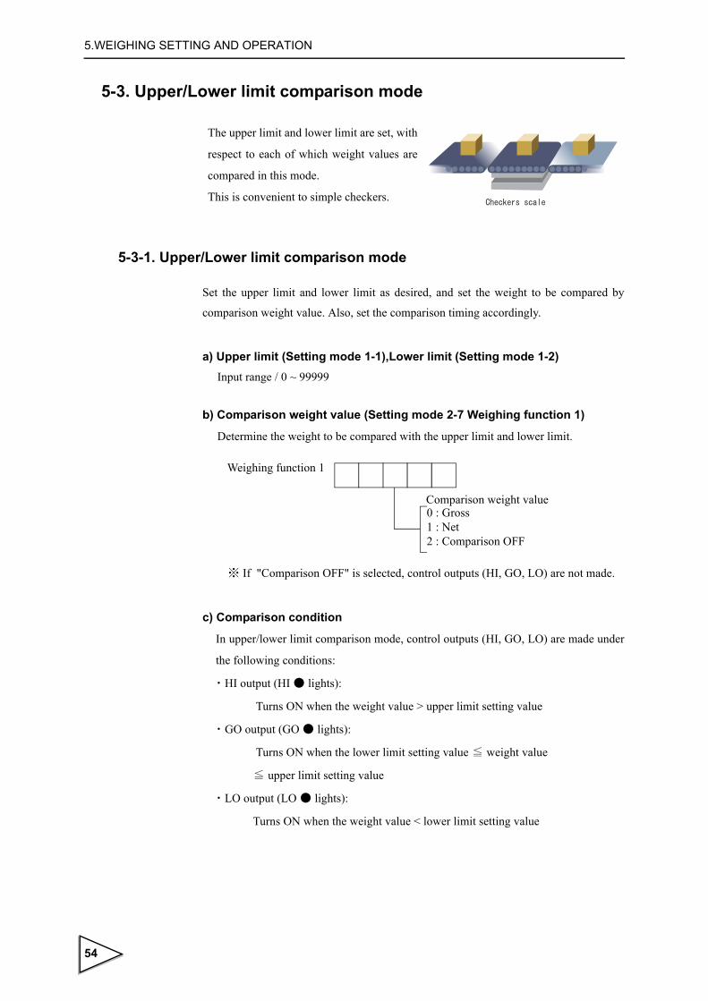
5.WEIGHING SETTING AND OPERATION
5-3. Upper/Lower limit comparison mode
5-3-1. Upper/Lower limit comparison mode
Set the upper limit and lower limit as desired, and set the weight to be compared by
comparison weight value. Also, set the comparison timing accordingly.
a) Upper limit (Setting mode 1-1),Lower limit (Setting mode 1-2) Input range / 0 ~ 99999
b) Comparison weight value (Setting mode 2-7 Weighing function 1)
Determine the weight to be compared with the upper limit and lower limit.
c) Comparison condition
In upper/lower limit comparison mode, control outputs (HI, GO, LO) are made under
the following conditions:
・HI output (HI ● lights):
Turns ON when the weight value > upper limit setting value
・ GO output (GO ● lights):
Turns ON when the lower limit setting value ≦ weight value
≦ upper limit setting value
・LO output (LO ● lights):
Turns ON when the weight value < lower limit setting value
The upper limit and lower limit are set, with
respect to each of which weight values are
compared in this mode.
This is convenient to simple checkers.
Comparison weight value0 : Gross1 : Net2 : Comparison OFF
Weighing function 1
※ If "Comparison OFF" is selected, control outputs (HI, GO, LO) are not made.
54

5.WEIGHING SETTING AND OPERATION
d) Comparison timing (Setting mode 2-7 Weighing function 1)
Determine the timing of comparison with the upper limit and lower limit.
※ If "Compare in a stable condition" is selected, comparison is made only in a stable
condition (while " " is lit).
※ Determine whether near zero is ON or OFF by near zero comparison mode.
Also, "except near zero" indicates a state in which " " is unlit.
e)Time chart in upper/lower limit comparison mode
Comparison timing0 : Compare regularly1 : Compare in a stable condition.2 : Compare regularly except near zero.3 : Compare in a stable condition except near zero.
Weighing function 1
STAB●
NZ○
0
Near zero
Lower Limit
Upper Limit
Weight value
Time
Stable
Near zero
OFF
ON
ON
ON
ON
OFF
HI
GO
LO
OFF
OFF
OFF
OFF
ON
(STAB)
(NZ)
HOLD
* 1
* 3
* 2Hold time t1
☆ Sending auto print data
55

5.WEIGHING SETTING AND OPERATION
* 1 : Determine the stable condition by stable detection mode (weighing function 2 in setting mode 2-8) and motion detection (setting mode 2-3 and 2-4).
*2 : To hold weight values, there is a need to set the auto print mode (weighing function 1 in setting mode 2-7) to 2 (auto print ON, weight value hold) in advance. Determine hold time t1 by setting mode 1-3 (input range: 0.0 - 9.9 sec). Also, to perform auto print, there is a need to set the auto print mode to auto print ON and also the communication mode (RS-232C I/F setting in setting mode 4-1) to 5 - 7 (communication mode 4 - 6). In upper/lower limit comparison mode, auto print data is sent at the time of change from a non-stable to a stable state beyond near zero.
* 3 : Control outputs are described as an example in which the comparison timing is set to compare regularly.
5-4. Over/Under comparison mode
5-4-1. Over/Under comparison mode
Set Target, Over, and Under as desired, and set the weight to be compared by comparison
weight value.
Also, set the comparison timing accordingly.
a) Target value (Setting mode 1-1)
Input range / 0 ~ 99999
b) Over (Setting mode 1-2), Under (Setting mode 1-3)
Input range / 0 ~ 9999
c) Comparison weight value (Setting mode 2-7 Weighing function 1)
Determine the weight to be compared with (target value + over) and (target value -
under)
Over and Under based on the target value
are set, with respect to each of which weight
values are compared in this mode.
This is convenient to simple checkers.
56

5.WEIGHING SETTING AND OPERATION
d) Comparison condition
In over/under comparison mode, control outputs (HI, GO, LO) are made under the
following conditions:
・ HI output (HI ● lights):
Turns ON when the weight value > (target value + over)
・GO output (GO ● lights):
Turns ON when (target value - under) ≦ weight value ≦ (target value + over)
・LO output (LO ● lights):
Turns ON when the weight value < (target value - under)
e) Comparison timing (Setting mode 2-7 Weighing function 1)
Determine the timing of comparison with (target value - under) and (target value +
over).
※ If "Compare in a stable condition" is selected, comparison is made only while
" " is lit (in a stable condition).
※ Determine whether near zero is ON or OFF by near zero comparison mode.
Also, "except near zero" indicates a state in which " " is unlit.
Comparison weight value0 : Gross 1 : Net 2 : Comparison OFF
Weighing function 1
※ If "Comparison OFF" is selected, control outputs (HI, GO, LO) are not made.
Comparison timing0 : Compare regularly 1 : Compare in a stable condition.2 : Compare regularly except near zero.3 : Compare in a stable condition except near zero.
Weighing function 1
STAB●
NZ○
57

5.WEIGHING SETTING AND OPERATION
f) Time chart in Over/Under comparison mode
* 1 : Determine the stable condition by stable detection mode (weighing function 2 in setting mode 2-8) and motion detection (setting mode 2-3 and 2-4).
*2 : To hold weight values, there is a need to set the auto print mode (weighing function 1 in setting mode 2-7) to 2 (auto print ON, weight value hold) in advance. Determine hold time t1 by setting mode 1-4 (input range: 0.0 - 9.9 sec). Also, to perform auto print, there is a need to set the auto print mode to auto print ON and also the communication mode (RS-232C I/F setting in setting mode 4-1) to 5 - 7 (communication mode 4 - 6). In over/under comparison mode, auto print data is sent at the time of change from a non-stable to a stable state beyond near zero.
* 3 : Control outputs are described as an example in which the comparison timing is set
to compare regularly.
0
Near zero
Target value - Under
Target value + Over
Weight value
Time
Stable
Near zero
OFF
ON
ON
ON
ON
OFF
HI
GO
LO
OFF
OFF
OFF
OFF
ON
(STAB)
(NZ)
HOLD
* 1
* 3
* 2Hold time t1
Target value
☆ Sending auto print data
58

5.WEIGHING SETTING AND OPERATION
5-5. Discharging control mode
If the start of weighing cannot be judged, the COMPLETE
Also, the HI, GO, and LO output signals cannot be used.
For use of this mode, affix the attached label to the front panel and rear panel to use as
COMPL (COMPLETE), SP2, and SP1.
5-5-1. Discharging control
Set Final, Compensation, and Set point 1 as desired. Set the weight to be compared by
comparison weight value.
Also, set the comparison timing accordingly.
a) Final (Setting mode 1-1), Set point 1 (Setting mode 1-3)
Input range / 0 ~ 99999
b) Compensation (Setting mode 1-2)
Input range / 0 ~ 9999
c) Comparison weight value (Setting mode 2-7 Weighing function 1)
Determine the weight to be compared with (final - compensation) and (final - Set
point 1).
signal cannot also be output.
A fixed amount is accurately discharged from a tank like a
hopper in this mode.
In this mode, after completion of the previous weighing,
when the weight drops below 25% of the fixed amount,
the state is judged as the next weighing is possible.
Comparison weight value0 : Gross1 : Net2 : Comparison OFF
Weighing function 1
※ If "2 : Comparison OFF" is selected, control outputs (COMPL, SP2, SP1) are not made.
59
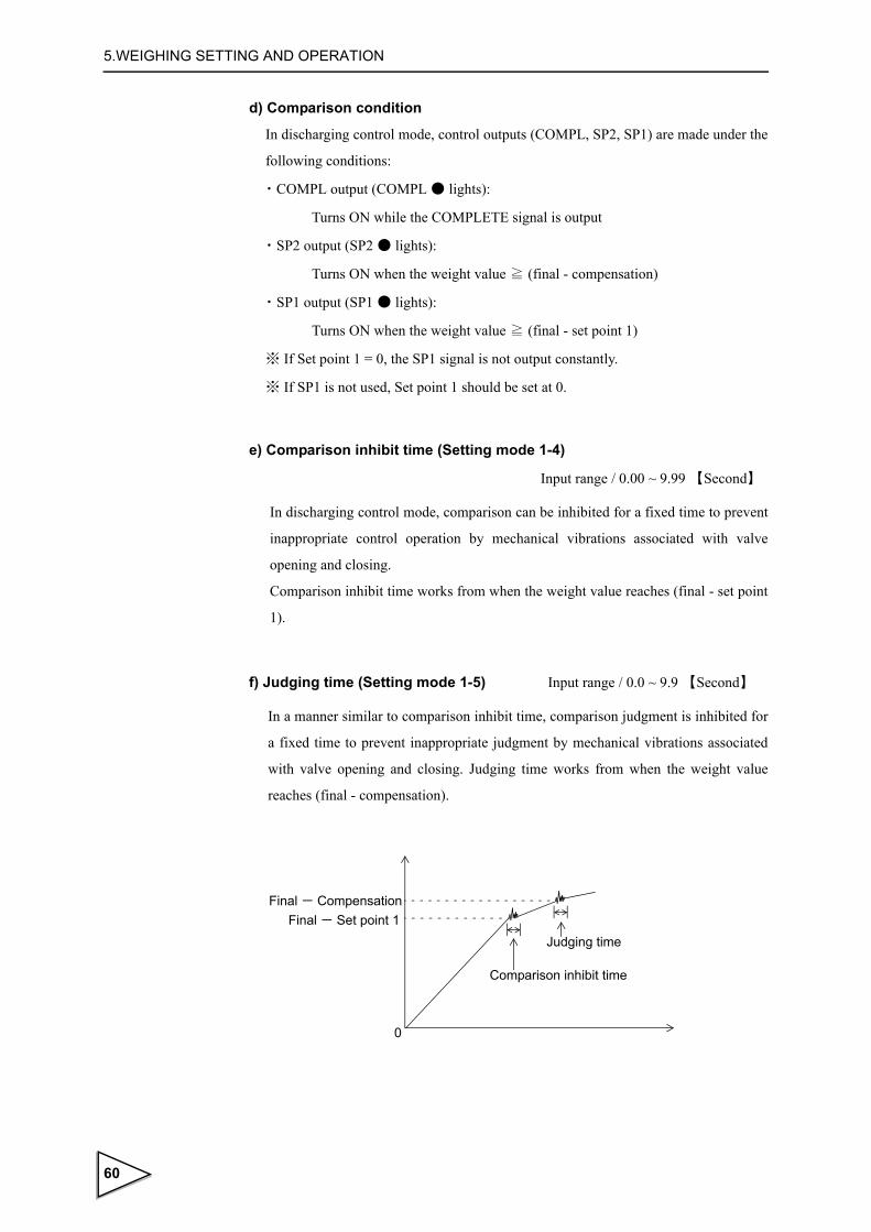
5.WEIGHING SETTING AND OPERATION
d) Comparison condition
In discharging control mode, control outputs (COMPL, SP2, SP1) are made under the
following conditions:
・COMPL output (COMPL ● lights):
Turns ON while the COMPLETE signal is output
・SP2 output (SP2 ● lights):
Turns ON when the weight value ≧ (final - compensation)
・SP1 output (SP1 ● lights):
Turns ON when the weight value ≧ (final - set point 1)
※ If Set point 1 = 0, the SP1 signal is not output constantly.
※ If SP1 is not used, Set point 1 should be set at 0.
e) Comparison inhibit time (Setting mode 1-4)
Input range / 0.00 ~ 9.99 【Second】
In discharging control mode, comparison can be inhibited for a fixed time to prevent
inappropriate control operation by mechanical vibrations associated with valve
opening and closing.
Comparison inhibit time works from when the weight value reaches (final - set point
1).
f) Judging time (Setting mode 1-5) Input range / 0.0 ~ 9.9 【Second】
In a manner similar to comparison inhibit time, comparison judgment is inhibited for
a fixed time to prevent inappropriate judgment by mechanical vibrations associated
with valve opening and closing. Judging time works from when the weight value
reaches (final - compensation).
0
Final - Set point 1Final - Compensation
Comparison inhibit time
Judging time
60
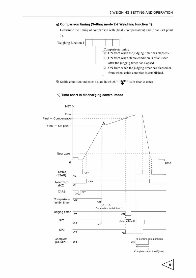
5.WEIGHING SETTING AND OPERATION
g) Comparison timing (Setting mode 2-7 Weighing function 1) Determine the timing of comparison with (final - compensation) and (final - set point
1).
※ Stable condition indicates a state in which " " is lit (stable state).
h) Time chart in discharging control mode
Comparison timing0 : ON from when the judging timer has elapsedv.1 : ON from when stable condition is established
after the judging timer has elapsed.2 : ON from when the judging timer has elapsed or
from when stable condition is established.
Weighing function 1
STAB●
0
Near zero
Final - Set point 1
Final
NET
Time
Stable
Near zero
TARE
Comparison
Judging timer
ON
ON
ON
ON
ON
OFF
SP1
SP2
CompleteON
Complete output timet3(Hold)
Judging time t2
ON
(STAB)
(NZ)
(COMPL)
Comparison inhibit time t1
ON
ON
OFF
OFF
OFF
OFF
OFF
OFF
OFF
OFF
☆ Sending auto print data
Final - Compensation
inhibit timer
61

5.WEIGHING SETTING AND OPERATION
* 1 : Determine the stable condition by stable detection mode (weighing function 2 in setting mode 2-8) and motion detection (setting mode 2-3 and 2-4).
*2 : To hold weight values, there is a need to set the auto print mode (weighing function 1 in setting mode 2-7) to 2 (auto print ON, weight value hold) in advance. In discharging control mode, weight values are held for the complete output time only under the above conditions. Determine complete output time t3 by setting mode 1-6 (input range: 0.0 - 9.9 sec). Also, to perform auto print, there is a need to set the auto print mode to auto print ON and also the communication mode (RS-232C I/F setting in setting mode 4-1) to 5 - 7 (communication mode 4 - 6). Auto print data is sent at the time of start of the COMPLETE signal output.
62

6.SYSTEM MODE
6. SYSTEM MODE
6-1. LOCK(soft)
Lock for protecting from false operation, refer to "16.THE LIST OF INITIAL SETTING VALUE" on P.115 regarding effective setting value for LOCK (soft). Select from ON/OFF.
6-2. PASSWORD
For future extension. normally, it is not used.
6-3. Self-check
This equipment is provided with the self-check function by which the memory is automatically checked to detect problems, and the visual check function by which the display can be checked visually.
While pressing the key, turn ON the power.With this, checking starts immediately.
※ The software version display may vary according to the time of purchase.
※ When the LOCK switch on the rear panel is ON, the NOV RAM is not checked.
※ Visually check the display.
※ Checking stops when there is any problem during memory checks.
※ If checking in progress stops or the display is not correct, it is faulty. Ask our agency
or us for repair.
LOCK20 : OFF1 : ON
LOCK10 : OFF1 : ON
Function key invalid・LOCK
Description Type1 Software version Display 2 Digit2 Check sum Display ←
3 ROM Check sum Check ← is displayed when error occurs.
4 All lighting on the display Display5 Status sequential lighting Visual6 7-segment lighting on the display Visual7 NOV RAM Read/Write Check Auto ← is displayed when error occurs.
8 PASS display and check end Display
63

7.EXTERNAL INPUT/OUTPUT SIGNALS (CONTROL CONNECTOR)
7. EXTERNAL INPUT/OUTPUT SIGNALS (CONTROL CONNECTOR)
The Input/Output circuit and internal circuit are photocoupler-insulated electrically.
7-1. Control connector-pin assignment
※ COM and SG are isolated electrically.
※ The power supply voltage is not output externally.
※ For use in comparison mode 2 (discharging control mode), affix the attached "COMPL/SP2/SP1" label to "HI/GO/LO" on the rear panel.
7-2. Equivalent circuit (Input)
A signal is inputted to the signal input circuit by short-circuiting or opening the input
terminal and the COM terminal. Short-circuiting is effected by means of a contact (such
as a relay or a switch) or a noncontact (such as a transistor or an open-collector TTL).
Input TARE COMOutput HI (COMPL)
Output GO (SP2)
Output LO (SP1)
TXD
RX
DS
GTA
RE
CO
M HI
GO LO
COMP
LS
P2
SP
1for rear panel
Vcc
F741-CInside
approx.
COM
Transistor
+12V
TTL Open Collector*
Push Toggle Switch Relay
ON when IN is HI
ININ
Open OFFShort ON
・Do not apply external voltage to the signal input circuit.
・The external element is required to withstand Ic=10mA.
・Leakage from the external element is required to be 100μA or below.
SwitchIC=6mA
64

7.EXTERNAL INPUT/OUTPUT SIGNALS (CONTROL CONNECTOR)
7-3. Equivalent circuit (Output)
The signal output circuit is open-collecter output of a transistor.
7-4. External input signal
7-4-1. Tare (Tare ON) < Edge input >
Subtract the tare at once by external input ON edge (OFF → ON), it brings the net
weight to zero.
The key operation also results in the same movement (only when the [TARE] key
is set at 1: valid in setting mode 2-9).
The range of 0 < Tare ≦ Capacity.
Spark killer
Load
Spark killer
DC Power
Varistor
Load
AC power
Relay
Vext
Output data Tr
0 OFF
1 ON
F741-C
Inside
Vcc +12V
COM
Vceo=30V(max)Ic =120mA (max)
・Use external power source (up to DC30V) for driving relay (Vext).
・Do not short-circuit the load, such as a coil of relay, that will break the output transistor.
・Connect a surge absorber or a speark killer to the relay circuit as shown in the draft so that to reduce noise trouble and extend the life of relay. Noise trouble can be reduced, and the relay’s life can be extended.
・Transistor status
TARE
OFF
ON
Pulse width 50msec or more
65

7.EXTERNAL INPUT/OUTPUT SIGNALS (CONTROL CONNECTOR)
7-5. External output signal
The meanings of the external output signals differ according to the state of the
comparison mode.
Determine the comparison mode by weighing function 1 (setting mode 2-7).
7-5-1. When comparison mode 0 (Upper/Lower limit comparison mode) is set
● HI,GO,LO
Respective output signals turn ON under the following
・HI : Weight value > Upper LimitSetting value
・GO : Lower Limit Setting value ≦ Weight value
≦ Upper Limit Setting value
・LO :Weight value < Lower LimitSetting value
7-5-2. When comparison mode 1 (Over/Under comparison mode) is set
● Respective output signals turn ON under the following conditions.
・HI : Weight value > (Target value + Over)
・GO : (Target value - Under) ≦ Weight value ≦ (Target value + Over)
・LO : Weight value < (Target value - Under)
7-5-3. When comparison mode 2 (Discharging control mode) is set
※ Use the output signals not as HI, GO, and LO, but as COMPL (COMPLETE), SP2,
and SP1.
● COMPL,SP2,SP1
Respective output signals turn ON under the following conditions.
・COMPL : While the COMPLETE signal is output
・SP2 : Weight value ≧ Final - Compensation
・SP1 : Weight value ≧ Final - Set point 1
・If Set point 1 = 0, the SP1 signal is not output constantly.・Determine the COMPLETE signal output timing by weighing function 1
(setting mode 2-7).・After output of the COMPLETE signal, only when the weight once drops
below 25% of the fixed amount, it is judged that the next weighing can be started. If the start of weighing cannot be judged, the COMPLETE signal cannot also be output.
66

8.INTERFACE
8. INTERFACE
8-1. RS-232C Interface[232]
8-1-1. Communication specifications
1.Specifications
Signal level : Based on the RS-232C
Transmitting distance : Approx. 15m
Transmitting method : Asynchronous, full duplex
Transmitting speed : 1200, 2400, 4800, 9600, 19200 or 38400 bps selectable
Bit configuration : Start 1 bit
Character length 7 or 8 bits selectable
Stop 1 or 2 bits selectable
Parity none, odd or even selectable
Code : ASCII
2.Connector pin assignment
8-1-2. Cable
RS-232C connector
TXD Transmitted DataRXD Received DataSG Signal Ground
Cross type
RXDTXD
SG
1 CD2 RXD3 TXD4 DTR6 DSR7 RTS8 CTS5 GND9 RI
Host computerF741-C (9-pin)
67

8.INTERFACE
The above diagram is for connecting a host computer as a DTE (Data Terminal
Equipment) device. If it is a DCE (Data Circuit-terminating Equipment) device, connect
pin to pin (DTR to DTR, DSR to DSR etc.).
Cables should be prepared after checking connector type and pin assignments of the
connected device.
8-1-3. Setting values for RS-232C
1.Set the RS-232C port of this equipment.
2. The initial set for RS-232C port of connecting personal computer and
sequencer should be the same setting of F741-C.
RXDTXD
SG
8 CD3 RXD2 TXD
20 DTR6 DSR4 RTS5 CTS7 GND1 FG
Host computerF741-C
Cross type (25-pin)
Baud rate0 : 1200bps1 : 2400bps2 : 4800bps3 : 9600bps4 : 19200bps5 : 38400bps
Communication mode
Character length0 : 7bit1 : 8bit
Stop bit0 : 1bit1 : 2bit
Parity bit0 : None1 : Odd2 : Even
0 : Communication mode0/CR1 : Communication mode0/CR+LF2 : Communication mode13 : Communication mode24 : Communication mode3
5 : Communication mode46 : Communication mode57 : Communication mode6
RS-232C I/F (Setting Mode 4-1)
Auto print and [PRINT] key operation are valid.
68

8.INTERFACE
8-1-4. Communication mode
・Communication mode0F741-C communicates with the command from the host computer.
The terminator can be selected “CR” or “CR+LF”.
・Communication mode1
F741-C sends Gross weight continuously.
Command is invalid at this mode.
・Communication mode2
F741-C sends net weight continuously.
Command is invalid at this mode.
・Communication mode3
F741-C sends gross weight and net weight continuously.
Command is invalid at this mode.
・Communication mode4
The gross weight is sent once at auto-print time or when the key is pressed.
Command is invalid at this mode.
・Communication mode5
The net weight is sent once at auto-print time or when the key is pressed.
Command is invalid at this mode.
Transmission on format1 (22byte)
Transmission on format2 (22byte)
Transmission on format3 (24byte)
Transmission on format1 (22byte)
Transmission on format2 (22byte)
69

8.INTERFACE
・Communication mode6
The gross weight and net weight are sent once at auto-print time or when the key
is pressed.
Command is invalid at this mode.
Transmission on format3 (24byte)
For the auto print function, see "8-1-5.Transmission on format" on page 71. For the auto print function, see "8-1-8.About the auto print function" on page 77.
Request
About the timing of continuous sending
The continuous sending interval in the case where any of communication modes 1 to 3 is selected is as shown below according to the status of the communication baud rate setting.
Communication baud rate Continuous sending interval
38400 bps 100 times/sec.
19200 bps 50 times/sec.
9600 bps 25 times/sec.
4800 bps 12 times/sec.
2400 bps 6 times/sec.
1200 bps 3 times/sec.
70

8.INTERFACE
8-1-5. Transmission on format
・Transmission on format1
・Transmission on format2
・Transmission on format3
0 1 2 3 4 5 6 7 8 9 10 11 12 13 14 15 16 17 18 19 20 21
G S ,*1 *2 *3 *4, , , , CR LF
HEADER Gross weight, 5-digit + decimal pointSign
+ or -
±*5 ,
HEADER Net weight, 5-digit + decimal pointSign
+ or -
0 1 2 3 4 5 6 7 8 9 10 11 12 13 14 15 16 17 18 19 20 21
N T ,*1 *2 *3 *4, , , , CR LF±*5 ,
0 1 2 3 4 5 6 7 8 9 10 11 12 13 14 15 16 17 18 19 20 21 22 23
W T *1 *2 *3 *4 ±
HEADER Net weight, 5-digit
Sign (gross weight)+ or -
Gross weight, 5-digit
*5SOH STX ETX BCC
Sign (net weight)+ or -
±
For BCC calculationEach ASCII code of SOH,STX and ETX
SOH : 01 STX : 02 ETX : 03
BCC : Block check characterIt is calculated as the XOR of the transmitted character (Hexadecimal).
*6
*1 O : Overload (LOAD,OFL) S : Stable M : Unstable H : Hold Priority : H > O > (S or M)
*4 N : Near zero OFF Z : Near zero ON
*2 A : Zero tracking OFF T : Zero tracking ON Z : Zero error (ZARM) Priority : Z > (A or T)
*5 Unit 0 : None 5 : N 1 : t 6 : oz 2 : g 7 : kN 3 : kg 4 : lb
*3 Upper/lower limit comparison and over/ under comparison modes
H : Upper limit/Over ONL : Lower limit/Under ONG : Upper limit/Over and
Lower limit/Under OFFN : Upper limit/Over and
Lower limit/Under ONF : Comparison OFF
Priority : N> (H or L),F > G
Discharging control Mode0 : Set point 1,Final,Complete OFF 1 : Set point 1 ON 2 : Final ON C : Complete ON F : Comparison OFF Priority : C> 2 > 1,F> 0
*6 Decimal place 0 : 01 : 0.0 2 : 0.00 3 : 0.000
71

8-1-6. Communication format
・Reading out the gross weight (sign, 5-digt weight value, decimal point)
・Reading out the net weight (sign, 5-digit weight value, decimal point))
・Reading out the tare weight (sign, 5-digit weight value, decimal point)
・Reading out the status 1(7-digit)
Host
F741-C
R CR
R A + 1 0 0 0 0. CR
A
LF
Host
F741-C
R CR
R B + 1 0 0 0 0. CR
B
LF
Host
F741-C
R CR
R C + 1 0 0 0 0. CR
C
LF
0:OFF1:ON
Rear LOCK SW
displayWeight 0:Gross
Weight valueHold
Weight valueZero error
Weight valueStable
In tare subtraction 0:OFF1:ON
1:Net
Host
F741-C
R CR
R D 0 0 0 0 0 00 CR
D
LF
5 : - LOAD4 : + LOAD3 : OFL32 : OFL21 : OFL10 :
7 : Calibration error
6 : Excitation voltage
Weight value error
0:OFF1:ON
0:OFF1:ON
error
0:OFF1:ON
72

・Reading out the status 2 (7-digit)
・Reading out the status 3 (7-digit)
・Write in the set value
※ For setting value No., refer to "8-1-7.Setting value communication format" on P.76.
・Read out the set value
※ For setting value No., refer to "8-1-7.Setting value communication format" on P.76.
Host
F741-C
R CR
R E 0 0 0 0 0 00 CR
E
LF
NZ
HI
GO
LO
COMPL
SP2
SP1
Upper/Lower limit comparison mode・Over/Under comparison mode
Discharging control mode
Host
F741-C
R CR
R F 0 0 0 0 0 00 CR
F
LF
OFL1
OFL2
OFL3
Calibration error0 ~ 9
Excitation voltage
- LOAD
+ LOAD
error
Host
F741-C
W CR
Setting value No. Setting value
LF
※ No return data
Host
F741-C
W
W CR
CR
Setting value No.
Setting value
Setting value No.
LF
73
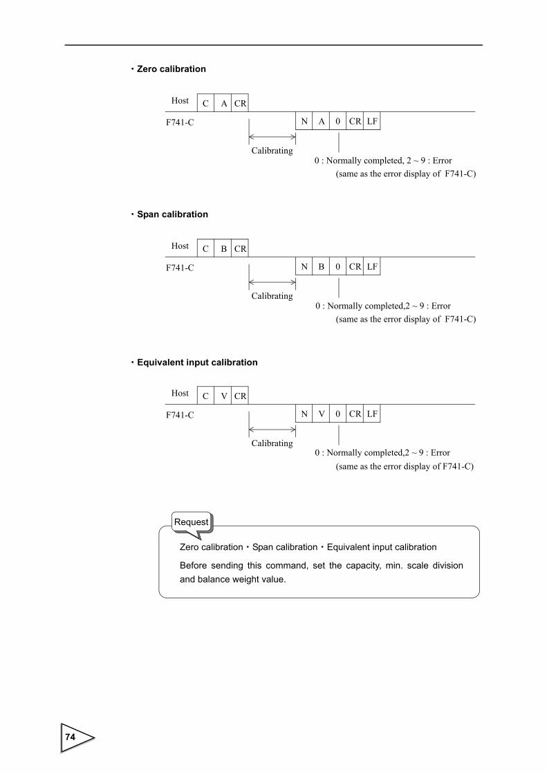
・Zero calibration
・Span calibration
・Equivalent input calibration
Host
F741-C
C A
N 0 CRA
Calibrating0 : Normally completed, 2 ~ 9 : Error
(same as the error display of F741-C)
CR
LF
Host
F741-C
C B
N 0 CRB
Calibrating0 : Normally completed,2 ~ 9 : Error
(same as the error display of F741-C)
CR
LF
Host
F741-C
C V
N 0 CRV
Calibrating0 : Normally completed,2 ~ 9 : Error
(same as the error display of F741-C)
CR
LF
Zero calibration・Span calibration・Equivalent input calibration
Before sending this command, set the capacity, min. scale division and balance weight value.
Request
74

・Gross weight selection
・Net weight selection
・Tare subtraction
・Tare subtraction reset
・Digital zero
・Digital zero reset
Host
F741-C
C C
※ No return data
CR
Host
F741-C
C D
※ No return data
CR
Host
F741-C
C E
※ No return data
CR
Host
F741-C
C F
※ No return data
CR
Host
F741-C
C G
※ No return data
CR
Host
F741-C
C H
※ No return data
CR
75

8-1-7. Setting value communication format
Use the following for reading and writing set values.
Set Point 2 W 1 1 CR LF (When LOCK1 can not write in)
Final (Target value) W 1 2 CR LF (When LOCK1 can not write in)
Over W 1 3 0 CR LF (When LOCK1 can not write in)
Under W 1 4 0 CR LF (When LOCK1 can not write in)
Compensation W 1 5 0 CR LF (When LOCK1 can not write in)
Judging time W 2 0 0 0 0 CR LF (When LOCK2 can not write in)
Comparison inhibit time W 2 1 0 0 CR LF (When LOCK2 can not write in)
Upper limit W 2 2 CR LF (When LOCK1 can not write in)
Lower limit W 2 3 CR LF (When LOCK1 can not write in)
Near zero W 2 4 CR LF (When LOCK1 can not write in)
Tare weight W 2 5 CR LF (When LOCK1 can not write in)
Complete output time W 2 8 0 0 0 CR LF (When LOCK2 can not write in)
(Hold)
Weighing function 1 W 3 1 CR LF (When LOCK2 can not write in)
Weighing function 2 W 3 2 0 CR LF (When LOCK2 can not write in)
Function key invalid W 3 4 CR LF
Digital filter W 3 5 0 0 CR LF (When LOCK2 can not write in)
Motion detection period W 3 6 0 0 0 CR LF (When LOCK2 can not write in)
Motion detection range W 3 7 0 0 0 CR LF (When LOCK2 can not write in)
Zero tracking period W 3 8 0 0 0 CR LF (When LOCK2 can not write in)
Zero tracking range W 3 9 0 CR LF (When LOCK2 can not write in)
Setting value No. 5-digit setting value (max.)
※ Where the setting is 0, do not enter other values than 0.
76
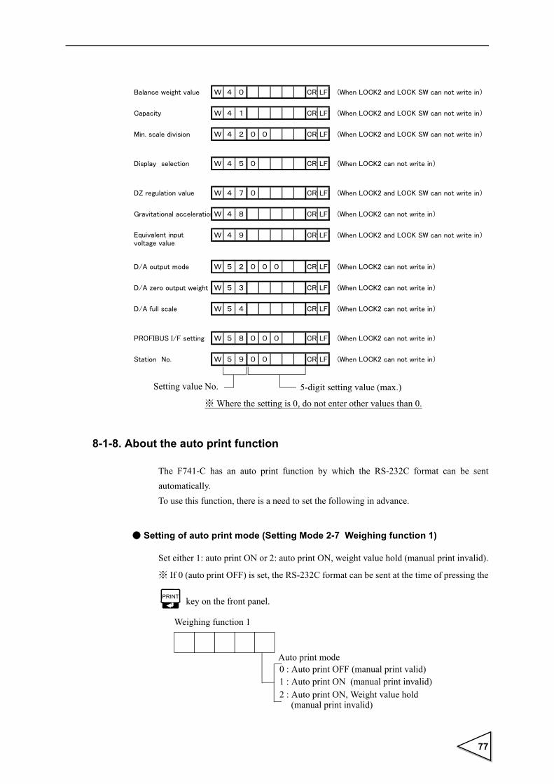
8-1-8. About the auto print function
The F741-C has an auto print function by which the RS-232C format can be sent automatically. To use this function, there is a need to set the following in advance.
● Setting of auto print mode (Setting Mode 2-7 Weighing function 1)
Set either 1: auto print ON or 2: auto print ON, weight value hold (manual print invalid).
※ If 0 (auto print OFF) is set, the RS-232C format can be sent at the time of pressing the
key on the front panel.
Balance weight value W 4 0 CR LF (When LOCK2 and LOCK SW can not write in)
Capacity W 4 1 CR LF (When LOCK2 and LOCK SW can not write in)
Min. scale division W 4 2 0 0 CR LF (When LOCK2 and LOCK SW can not write in)
Display selection W 4 5 0 CR LF (When LOCK2 can not write in)
DZ regulation value W 4 7 0 CR LF (When LOCK2 and LOCK SW can not write in)
Gravitational accelerationW 4 8 CR LF (When LOCK2 can not write in)
W 4 9 CR LF (When LOCK2 and LOCK SW can not write in)
D/A output mode W 5 2 0 0 0 CR LF (When LOCK2 can not write in)
D/A zero output weight W 5 3 CR LF (When LOCK2 can not write in)
D/A full scale W 5 4 CR LF (When LOCK2 can not write in)
PROFIBUS I/F setting W 5 8 0 0 0 CR LF (When LOCK2 can not write in)
Station No. W 5 9 0 0 CR LF (When LOCK2 can not write in)
Equivalent inputvoltage value
Setting value No. 5-digit setting value (max.)
※ Where the setting is 0, do not enter other values than 0.
Weighing function 1
2 : Auto print ON, Weight value hold
0 : Auto print OFF (manual print valid)1 : Auto print ON (manual print invalid)
Auto print mode
(manual print invalid)
77

● Setting of communication mode (Setting mode 4-1 RS-232C I/F setting)
Set any of "5 : Communication mode 4", "6 : Communication mode 5",
"7 : Communication mode 6".
The timing of auto sending of the RS-232C format differs according to the setting state
of the comparison mode.
● Timing of auto sending of the RS-232C format
(1)Comparison mode 0(Upper/Lower limit comparison mode)
It is sent at the time of change from a non-stable to a stable state beyond near zero.
(2)Comparison mode 1(Over/Under comparison mode)
It is sent at the time of change from a non-stable to a stable state beyond near zero.
(3)Comparison mode 2(Discharging control mode)
It is sent at the time of start of the COMPLETE signal output.
※ Determine the comparison mode by setting mode 2-7 (Weighing function 1).
RS-232C I/F setting
0 : Communication mode 0 / CR1 : Communication mode 0 / CR + LF2 : Communication mode 13 : Communication mode 24 : Communication mode 3 5 : Communication mode 46 : Communication mode 57 : Communication mode 6
Communication mode
Auto print and [PRINT] key operation are valid.
Weighing function 1
2 : Discharging control mode1 : Over / Under comparison mode0 : Upper / Lower limit comparison mode
Comparison mode
78
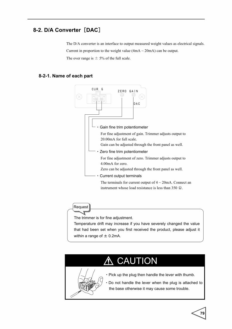
8-2. D/A Converter[DAC]
The D/A converter is an interface to output measured weight values as electrical signals.
Current in proportion to the weight value (4mA ~ 20mA) can be output.
The over range is ± 5% of the full scale.
8-2-1. Name of each part
・ Gain fine trim potentiometer
For fine adjustment of gain. Trimmer adjusts output to 20.00mA for full scale.Gain can be adjusted through the front panel as well.
・ Zero fine trim potentiometer
For fine adjustment of zero. Trimmer adjusts output to 4.00mA for zero.Zero can be adjusted through the front panel as well.
The terminals for current output of 4 ~ 20mA. Connect an instrument whose load resistance is less than 350 Ω.
・ Current output terminals
The trimmer is for fine adjustment. Temperature drift may increase if you have severely changed the value that had been set when you first received the product, please adjust it within a range of ± 0.2mA.
Request
CAUTION・Pick up the plug then handle the lever with thumb.
・Do not handle the lever when the plug is attached to the base otherwise it may cause some trouble.
79

・Taking current output signals
Connect an external equipment (load resistance 350Ω or less) between CUR.(+) ~ G(-)
of F741-C.
8-2-2. Specifications
Weight values are output as converted to analog signals of current. Zero output weight value and full scale weight value can be set.
Current output 4mA ~ 20mA(Load resistance 350Ω or less)
D/A conversion speed 200 times/sec.
Resolution 1/10000
Over range ± 5% of the full scale (3.2mA ~ 20.8mA)
Zero drift Within 0.3μV/ ℃
Gain drift Within 30ppm/ ℃
Non-linearity Within 0.02%/FS
※ Not including the drift of the analog input section
Output connector Cage clamp type terminal board (two-piece type)
Potentiometer A potentiometer to readjust (fine-adjust) ZERO (4mA) and
GAIN (20mA) is placed on the rear panel.
+
-
External equipment
Load resistance:350Ω or less
SIG
GND
← Inside Outside →
CUR.(+)
F741-C
G(-)
CAUTIONDo not apply voltage or current to the current output terminal externally by mistake. Doing so will cause breakage.
80

(The adjustable range is a few percentage.)
(4mA and 20mA are factory-adjusted.)
8-2-3. Method of adjusting the d/a zero and gain
The D/A converter of the F741-C obtains analog output by setting the range of the weight value to output 4mA of current and the weight value to output 20mA of current, respectively. Input each setting value and select D/A output mode in setting mode 4. When tied to the weight value is selected, it outputs the current to indicated value. Therefore, while the indicated value is held, the analog output is also held.
a) D/A output mode (Setting mode 4-2)
b) D/A zero output weight (Setting mode 4-3) Input range / 0 ~ 99999Input the weight value to output 4mA.
c) D/A full scale (Setting mode 4-4) Input range / 0 ~ 99999
Input the range of the weight value to output 20mA.
Current(mA)
20
4
D/A zero output weight setting
Resolution 1/10000
D/A full scale settingWeight value
Output mode0 : Gross 1 : Net
D/A output mode
Test mode0 : Tied to the weight value1 : 4mA fixed output2 : 20mA fixed output
81

ExampleWhen setting is as follows:
D/A output mode : 01
D/A zero output weight : 00500
D/A full scale : 02000
8-2-4. About D/A resolution
The resolution of the D/A converter is 1/10000 with respect to 4 ~ 20mA.
That is, the minimum unit of current is as follows:
(20 ~ 4mA) × 1/10000 = 1.6μA
Also, the minimum unit of weight value is as follows:
(D/A Full Scale setting value) × 1/10000
Current(mA)
20
4
D/A zero output weight setting
Resolution 1/10000
D/A full scale setting
Net500 2000 2500
Net Current (mA)
4805001000150025002520
3.844.008.00
12.0020.0020.16
Zero
Full scale
82

8-3. Profibus interface[PRF]
Introduction
The F741-C PROFIBUS I/F is described in this chapter.
For reading it, basic knowledge of PLC and PROFIBUS is required.
For basic knowledge of PROFIBUS, see specialized references.
8-3-1. Specifications
・The F741-C loaded with the PROFIBUS I/F can be connected as a slave device to a
PROFIBUS fieldbus. (Compatible with PROFIBUS-DP V0.)
・Communication speed: 9.6 kbps - 12 Mbps (automatically following the master)
・Occupied memory: OUT/12 bytes (6 words)
IN/20 bytes (10 words)
※ In allocation, be careful to prevent the address from overlapping with other slaves.
・Station No. : 0 - 125
・Sync mode and freeze mode are supported.
・Special clear mode (Fail safe mode) is not supported.
8-3-2. DimensionsF741-C rear panel with the PROFIBUS I/F option mounted
83

8-3-3. Name of each part
a) Communication connector
This is a connector (9-pin D-SUB connector socket type) for connecting the F741-C with
PROFIBUS. The function of each signal is as follows:
※ Prepare 9-pin D-Sub connector plug type for the connection.
※ Use a PROFIBUS-qualified connector and cable.
For PROFIBUS-qualified products, contact the PROFIBUS Organization.
※ When the F741-C comes at the end, be sure to connect a terminal resistor.
For the method of connecting the terminal resistor, check with specialized references.
b) Status LED
・LINK : Lights while the F741-C is linked with the master.
・RUN : Lights when the F741-C is normal.
a) Communication connector b) Status LED
Pin No. Signal name Function
1 - (Not used)
2 - (Not used)
3 RXD / TXD-P Data reception/send data plus
4 CNTR-P Data reception/send data plus
5 DGND Data ground (0V)
6 VP Communication power (V5)
7 - (Not used)
8 RXD / TXD-N Data reception/send data minus
9 - (Not used)
84
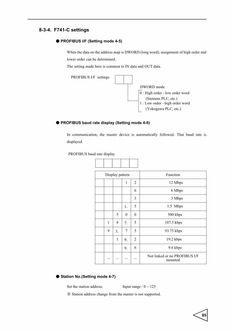
8-3-4. F741-C settings
● PROFIBUS I/F (Setting mode 4-5)
When the data on the address map is DWORD (long word), assignment of high order and
lower order can be determined.
The setting made here is common to IN data and OUT data.
● PROFIBUS baud rate display (Setting mode 4-6)
In communication, the master device is automatically followed. That baud rate is
displayed.
● Station No.(Setting mode 4-7)
Set the station address. Input range / 0 ~ 125
※ Station address change from the master is not supported.
PROFIBUS I/F settings
DWORD mode0 : High order - low order word (Siemens PLC, etc.)1 : Low order - high order word (Yokogawa PLC, etc.)
Display pattern Function
1 2 12 Mbps
6 6 Mbps
3 3 Mbps
1. 5 1.5 Mbps
5 0 0 500 kbps
1 8 7. 5 187.5 kbps
9 3. 7 5 93.75 kbps
1 9. 2 19.2 kbps
9. 6 9.6 kbps
- - - -Not linked or no PROFIBUS I/F
mounted
PROFIBUS baud rate display
85

8-3-5. Address map
This product occupies OUT/12 bytes (6 words) and IN/20 bytes (10 words) memory.
In allocation, be careful to prevent the address from overlapping with other slaves.
The data used for writing and reading is handled with the decimal point ignored, but the
F741-C recognizes the decimal point at the specified digit position.
For example, when "50" is written in Judging Time from PLC to F741-C, the F741-C
handles it as 5.0 [sec].
* In the following explanation, ON corresponds to 1 and OFF corresponds to 0.
Also, an ON edge corresponds to (0 → 1), and an OFF edge corresponds to (1 → 0).
a) OUT data (6 words)
PLC → F741-C
15 14 13 12 11 10 9 8 7 6 5 4 3 2 1 0 mode 0 mode 1Write data (high order) (low order)
15 14 13 12 11 10 9 8 7 6 5 4 3 2 1 0
Write data (low order) (high order)
15 14 13 12 11 10 9 8 7 6 5 4 3 2 1 0
Undefined
15 14 13 12 11 10 9 8 7 6 5 4 3 2 1 0
Undefined
15 14 13 12 11 10 9 8 7 6 5 4 3 2 1 0
Command No.
15 14 13 12 11 10 9 8 7 6 5 4 3 2 1 0
⑨ ⑧ ⑦ ⑥ ⑤ ④ ③ ② ① Command bit
① R/W (R : 1 / W : 0)② Command request③ “Keep alive” confirmation request
④ Digital zero⑤ Digital zero reset⑥ TARE⑦ TARE reset⑧ Display switching; gross weight⑨ Display switching; net weight
※Do not perform more than two operations of ④~⑨ at the same time.
(bit)DWORD mode
4th word
1st word
2nd word
3rd word
(bit)DWORD
5th word
6th word(bit)
(bit)
(bit)
(bit)
86

〈Explanation about OUT data〉
◎ Write data
Use this when writing data by using the command request.
Write data consists of 32-bit binary (2 words), the high order and low order of which
are changed by DWORD mode (PROFIBUS I/F in setting mode 4-5) of the F741-C.
◎ Command No.
For writing data, specify the command No. of the data you want to specify in
advance. The high byte is not used.
For command Nos., see the following list.
Be aware that Command No. response and Reading data are both adjusted to 0 and
the Command response is turned ON for invalid command NO..
Moreover, when LOCK is activating, it is not possible to write it.
(The Command response returns ON. )
※ In communication, setting values are all handled with the decimal point ignored.
◎ R/W(R : 1 / W : 0)
Specify the command "READ/WRITE."
READ : Turn ON for reading various setting values of the F741-C.
WRITE : Turn OFF for writing setting values to the F741-C.
Setting value Command No. Input range
Set point 1 11 0 ~ 99999 LOCK1
Final (Target value) 12 0 ~ 99999 LOCK1
Over 13 0 ~ 9999 LOCK1
Under 14 0 ~ 9999 LOCK1
Compensation 15 0 ~ 9999 LOCK1
Judging time 20 0 ~ 99 LOCK2
Comparison inhibit time 21 0 ~ 999 LOCK2
Upper limit 22 0 ~ 99999 LOCK1
Lower limit 23 0 ~ 99999 LOCK1
Near zero 24 0 ~ 99999 LOCK1
Tare setting 25 0 ~ 99999 LOCK1
Complete output time
(Hold time)28 0 ~ 99 LOCK2
87

◎ Command request
Give an ON edge to execute the read or write command.
◎ "Keep alive" confirmation request
By operating this bit, whether the F741-C is operating normally can be confirmed.
The F741-C side outputs this bit to the "keep alive" confirmation response as its state
is inverted.
◎ Digital zero
Gross weight is zeroed by the ON edge.
◎ Digital zero reset
Digital zero is reset by the ON edge.
◎ TARE
Tare subtraction is executed by the ON edge.
◎ TARE reset
Tare subtraction is reset by the ON edge.
◎ Display switching: Gross
Weight display is switched to gross weight by the ON edge.
◎ Display switching: Net
Weight display is switched to net weight by the ON edge.
88

b) IN data (10 words)
F741-C → PLC
15 14 13 12 11 10 9 8 7 6 5 4 3 2 1 0 (bit)Gross weight
15 14 13 12 11 10 9 8 7 6 5 4 3 2 1 0 (bit)Gross weight
15 14 13 12 11 10 9 8 7 6 5 4 3 2 1 0 (bit)Net weight
15 14 13 12 11 10 9 8 7 6 5 4 3 2 1 0 (bit)Net weight
15 14 13 12 11 10 9 8 7 6 5 4 3 2 1 0 (bit)Read data
15 14 13 12 11 10 9 8 7 6 5 4 3 2 1 0 (bit)Read data
15 14 13 12 11 10 9 8 7 6 5 4 3 2 1 0 (bit)⑭ ⑬ ⑫ ⑪ ⑩ ⑨ ⑧ ⑦ ⑥ ⑤ ④ ③ ② ① Status 1
① Weight value hold② Weight value zero alarm③ Weight value stable④ In tare subtraction⑤ Weight display; gross weight/net weight (net: 1/gross: 0)⑥ Rear LOCK SW⑦ Weight value alarm
⑧ Near zero⑨ Upper limit/over⑩ Go⑪ Lower limit/under⑫ Set point 2⑬ Final Discharging control mode⑭ Complete
15 14 13 12 11 10 9 8 7 6 5 4 3 2 1 0 (bit)⑦ ⑥ ⑤ ④ ③ ② Status 2
① Calibration error number (0~9)② OFL1③ OFL2④ OFL3⑤ +LOAD⑥ -LOAD⑦ Excitation voltage error⑧ Decimal place (0~3)⑨ Unit (0~9)
15 14 13 12 11 10 9 8 7 6 5 4 3 2 1 0 (bit)Command No. response
15 14 13 12 11 10 9 8 7 6 5 4 3 2 1 0 (bit)⑩ ⑨ ⑧ ⑦ ⑥ ⑤ ④ ③ ② ① Command bit response
① R/W-
response② Command response
④ Remote READY (“1” is set after completion of initialization.)
⑤ Digital zero response⑥ Digital zero reset response⑦ Tare subtraction response⑧ Tare subtraction reset response⑨ Display switching; gross weight response⑩ Display switching; net weight response
(low order) (high order)
(low order) (high order)
(high order) (low order)
(low order) (high order)
(high order) (low order)
mode 0 mode 1(high order) (low order)
9th word
10th word
7th word
8th word
5th word
6th word
1st word
2nd word
3rd word
4th word
③“Keep alive” confirmation response(The state of the “keep alive” confirmation bit is set as it is inverted.)
Upper/Lower limit comparison modeOver/Under comparison mode
DWORD mode
DWORD
DWORD
⑧⑨ ①
DWORD
89
〈Explanation about IN data〉
◎ Gross weight (signed 32-bit binary / - 99999 ~ 99999)
Indicates gross weight. In the case of minus data, the highest-order bit becomes 1.
The gross weight indicated here is constantly updated. No request signal, etc., is
required.
The high order and low order are changed by DWORD mode (PROFIBUS I/F in
setting mode 4-5) of the F741-C.
◎ Net weight (signed 32-bit binary / - 99999 ~ 99999)
Indicates net weight. In the case of minus data, the highest-order bit becomes 1.
The net weight indicated here is constantly updated. No request signal, etc., is
required.
The high order and low order are changed by DWORD mode (PROFIBUS I/F in
setting mode 4-5) of the F741-C.
◎ Read data (signed 32-bit binary / - 99999 ~ 99999)
Indicates command No.-specified data. In the case of minus data, the highest-order
bit becomes 1.
The data indicated here is updated each time the ON edge of the command request is
received.
The high order and low order are changed by DWORD mode (PROFIBUS I/F in
setting mode 4-5) of the F741-C.
◎ Weight value hold
Turns ON while the weight value is held.
◎ Weight value zero error
Turns ON as a zero alarm (ZALM) occurs when the total amount of digital zero
exceeds the DZ regulation value by digital zero and zero tracking operation.
◎ Weight value stable
Turns ON while the weight value is stable.
◎ In tare subtraction
Turns ON when tare subtraction is performed.
◎ Weight display; gross weight/net weight
Turns ON while net weight is displayed, and OFF while gross weight is displayed.
90

◎ Rear LOCK SW
Turns ON when the rear LOCK SW is ON.
Turns OFF when the LOCK SW is OFF.
◎ Weight value error
Turns ON when any of ± LOAD, OFL1, OFL2, OFL3, and ZALM occurs.
◎ Near zero
Turns ON when the weight value ≦ near zero setting value.
◎ Upper limit / Over
Turns ON when the weight value > upper limit setting value in upper/lower limit
comparison mode.
Turns ON when the weight value > (Target value + Over) in over/under comparison
mode.
◎ Go
Turns ON when the lower limit setting value ≦ weight value ≦ upper limit setting
value in upper/lower limit comparison mode.
Turns ON when (Target value - Under) ≦ weight value ≦ (Target value + Over) in
over/under comparison mode.
◎ Lower limit / Under
Turns ON when the weight value < lower limit setting value in upper/lower limit
comparison mode.
Turns ON when the weight value < (Target value - Under) in over/under comparison
mode.
◎ Set point 1
Turns ON when the weight value ≧ (Final - Set point 1).
◎ Final
Turns ON when the weight value ≧ (Final - Compensation).
◎ Complete
Turns ON while the COMPLETE signal is output.
◎ Calibration error number (4-bit binary / 0 ~ 9)
Indicates calibration error number. "0" indicates no error (normal).
91

◎ OFL1
Turns ON when the net weight > 99999.
◎ OFL2
Turns ON when the gross weight > (Capacity + 9 scale divisions).
◎ OFL3
Turns ON when the gross weight > 99999.
◎+ LOAD
Turns ON when a signal exceeding the input signal range of the F741-C is inputted.
◎- LOAD
Turns ON when a signal dropping below the input signal range of the F741-C is
inputted.
◎ Excitation voltage error
Turns ON when the excitation voltage exerted on the loadcell is low.
◎ Decimal place (2-bit binary / 0 ~ 3)
Indicates the decimal point position (display selection in setting mode 3-5) of the
F741-C.
◎ Unit (4-bit binary / 0 ~ 9)
Indicates the unit setting (display selection in setting mode 3-5) of the F741-C.
◎ Command No. response
Returns the same value as the OUT data command No. when the command response
turns ON.
The high byte is not used.
◎ R/W response
Returns the same state as R/W of OUT data command bit.
◎ Command response
Turns ON upon completion of execution of the read or write command.
Turns OFF after confirming that the command request is OFF.
92

◎ Keep alive confirmation response
Constantly outputs the "keep alive" confirmation request as it is inverted.
◎ Remote ready
Turns ON when initialization of the F741-C is finished.
Various kinds of processing should be started after confirming that this bit is ON.
◎ Digital zero response
Turns ON after execution upon receiving the command bit "digital zero."
Turns OFF after confirming that the command bit "digital zero" is OFF.
◎ Digital zero reset response
Turns ON after execution upon receiving the command bit "digital zero reset."
Turns OFF after confirming that the command bit "digital zero reset" is OFF.
◎ TARE response
Turns ON after execution upon receiving the command bit "tare subtraction."
Turns OFF after confirming that the command bit "tare subtraction" is OFF.
◎ TARE reset response
Turns ON after execution upon receiving the command bit "tare subtraction reset."
Turns OFF after confirming that the command bit "tare subtraction reset" is OFF.
◎ Display switching: Gross response
Turns ON after execution upon receiving the command bit "display switching; gross
weight."
Turns OFF after confirming that the command bit "display switching; gross weight"
is OFF.
◎ Display switching: Net response
Turns ON after execution upon receiving command bit "display switching; net
weight."
Turns OFF after confirming that the command bit "display switching; net weight" is
OFF.
93

8-3-6. Read, write, and command procedures
a) Write procedure
(1) Turn OFF R/W, and specify WRITE.
(2) Specify the command No. of the setting value to write.
(3) Set data in the write data area.
(4) Execute the ON edge of the command request.
(5) On the F741-C side, take in the write data, and turn ON the command response.
(6) To turn OFF the command request, do it after confirming that the command response
is ON.
(7) When the command request is turned OFF, the command response also turns OFF.
Notice※ To execute the ON edge of the command request, make sure to do it
after confirming that the command request is OFF.
※ Immediately after power-on, the remote READY may not be ON. In
this case, execute processing after waiting until it becomes ON.
Command No.
R/W
R/W response
Command No.
Write data
Remote ready ON
response
Command request
Command response
94

b) Read procedure
(1) Turn ON R/W, and specify READ.
(2) Specify the command No. of the setting value to read.
(3) Execute the ON edge of the command request.
(4) On the F741-C side, set the setting value in the read data area, and turn ON the
command response.
(5) After confirming that the command response is ON, read the data.
(6) When the command request is turned OFF, the command response also turns OFF.
Notice※ To execute the ON edge of the command request, make sure to do it
after confirming that the command request is OFF.
※ Immediately after power-on, the remote READY may not be ON. In
this case, execute processing after waiting until it becomes ON.
R/W response
Command No.
Command request
Command response
R/W
Command No.
Read data
Remote ready ON
response
95

c) Command procedure
(1) Turn OFF all the bits from [ ④ digital zero] to [ ⑨ display switching; net weight] out
of the command bits.
(2) Turn ON the bit of the command to execute.
(3) On the F741-C side, execute the command, and then turn ON the corresponding
command bit response.
(4) To immediately turn OFF the command bit, do it after confirming that the command
bit response is ON.
(5) When the command bit is turned OFF, the corresponding command bit response also
turns OFF.
Notice※ To execute the ON edge of the command request, make sure to do it
after confirming that the command request is OFF.
※ To execute any one of the command bits from [ ④ digital zero] to [ ⑨
display switching; net weight], do not execute two or more simulta-
neously.
※ Immediately after power-on, the remote READY may not be ON. In
this case, execute processing after waiting until it becomes ON.
Command bit
Command bit response
Tare subtraction
Net
(TARE)
(TARE response)
Execution
Example) Execution of the command bit of [ ⑥ tare subtraction]
Remote ready ON
processing
96

9.OVER SCALE & ERROR
9. OVER SCALE & ERROR
9-1. Over scale
The weight error output turns ON.
※ Net weight = Gross weight - Tare weight
9-2. Calibration error
The input of A/D converter overflowed
Net weight > 99999
Gross weight > Capacity + 9 scale division
Gross weight > 99999
Error item Alarm message
The initial tare is beyond the zero adjustment range.
The initial tare is minus.
The input balance weight is beyonde the capacity.
The balance weight is “00000”.
The load cell output dose not reach the span adjustment range.
The load cell output is miunus.
The load cell output is beyond the span adjustment range.
The weight value is not stable and calibration stopped.
97

10.TROUBLE SHOOTING
10. TROUBLE SHOOTING
● Over-scale display
(A/D converter over)
Input signal from the load cell exceeds F741-C input signal range. Check whether the output of the load cell is within span adjutment range; Check there are breakages in the cable which is connected to the F741-C and the load cell; This display may appear when nothing is connected to the loadcell input terminal block on the rear panel.
(A/D converter minus over)
Input signal from the load cell is lower than F741-C input signal range range. Check whether the output of the load cell for falling short of the span adjustment range. Check there are breakages in the cable which is connected to the F741-C and the load cell. This display may appear when nothing is connected to the loadcell input terminal block on the rear panel.
(Net weight > 99999)
The net weight exceeds 99999 (display allowable limit). To put this over scale display back to a normal weight display, lower the input signal from the loadcell until the over scale display goes out.
(Gross weight > 99999)
Gross weight exceeds the Gross Over set value. Decrease the signal coming from the load cell until the normal display returns; or reset the Gross Over value.
(Gross weight > Capacity + 9 scale division)
Gross weight exceeds Capacity + 9 scale division. Decrease the signal coming from the load cell until the normal display returns.
Scale a capacity is primary data for the F741-C. You must re-calibrate if capacity is changed .
Do not change capacity to reset over scale message ( ).
Request
98

10.TROUBLE SHOOTING
● Calibration error display
(Calibration error)Initial dead load is above zero adjustment range.
Remove any excess load from load cell or scale. If " " is still displayed, connect a resistor between +EXC and -SIG load cell connections. This should shift the Zero point. Do Zeo calibration again.
・This table is for a 350Ω load cell.
・The temperature coefficient of the connected resistor directly influences the accuracy
of the indicator. Use a resistance having a temperature coefficient of 50ppm/℃ or more
(recommended value of about 5ppm/ ℃ ).
Resistor StrainIdeal Approx. μ-STRAIN mV/V
875 KΩ 866 KΩ 200 0.1437 KΩ 442 KΩ 400 0.2291 KΩ 294 KΩ 600 0.3219 KΩ 221 KΩ 800 0.4175 KΩ 174 KΩ 1000 0.5146 KΩ 147 KΩ 1200 0.6125 KΩ 124 KΩ 1400 0.7109 KΩ 110 KΩ 1600 0.897 KΩ 97.6 KΩ 1800 0.987.3 KΩ 86.6 KΩ 2000 1.079.4 KΩ 78.7 KΩ 2200 1.172.7 KΩ 73.2 KΩ 2400 1.267.1 KΩ 66.5 KΩ 2600 1.362.3 KΩ 61.9 KΩ 2800 1.458.2 KΩ 57.6 KΩ 3000 1.554.5 KΩ 54.9 KΩ 3200 1.651.3 KΩ 51.1 KΩ 3400 1.748.4 KΩ 48.7 KΩ 3600 1.845.9 KΩ 46.4 KΩ 3800 1.943.6 KΩ 43.2 KΩ 4000 2.041.5 KΩ 41.2 KΩ 4200 2.139.6 KΩ 39.2 KΩ 4400 2.237.9 KΩ 38.3 KΩ 4600 2.336.3 KΩ 36.5 KΩ 4800 2.434.8 KΩ 34.8 KΩ 5000 2.5
Connect the resistorbetween +EXC and -SIG.
+EXC
+SIG
-EXC
-SIG
99
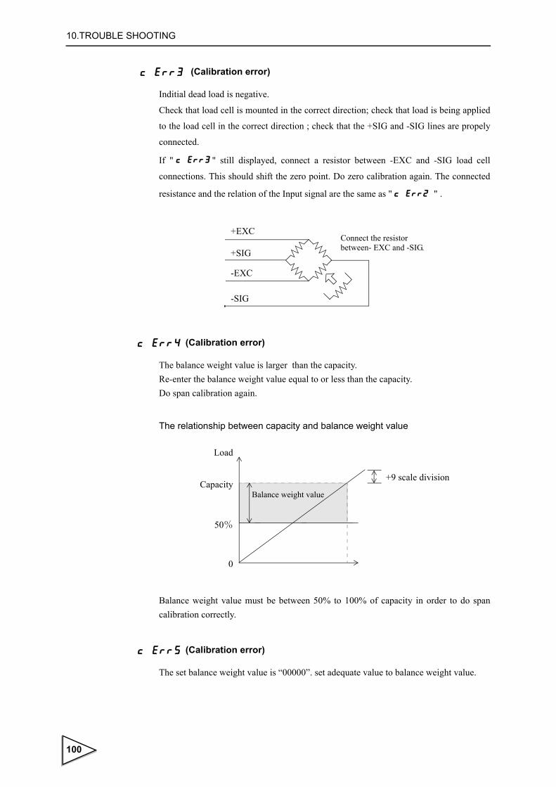
10.TROUBLE SHOOTING
(Calibration error)
Inditial dead load is negative.
Check that load cell is mounted in the correct direction; check that load is being applied
to the load cell in the correct direction ; check that the +SIG and -SIG lines are propely
connected.
If " " still displayed, connect a resistor between -EXC and -SIG load cell
connections. This should shift the zero point. Do zero calibration again. The connected
resistance and the relation of the Input signal are the same as " " .
(Calibration error)
The balance weight value is larger than the capacity. Re-enter the balance weight value equal to or less than the capacity. Do span calibration again.
The relationship between capacity and balance weight value
Balance weight value must be between 50% to 100% of capacity in order to do span calibration correctly.
(Calibration error)
The set balance weight value is “00000”. set adequate value to balance weight value.
+EXC
+SIG
-EXC
-SIG
Connect the resistorbetween- EXC and -SIG.
Balance weight value
Load
Capacity
50%
0
+9 scale division
100

10.TROUBLE SHOOTING
(Calibration error)
The load cell output dose not reach the span adjustment range of the F741-C. Check how load is applied to load cell; check load cell has sufficient outpul (mV/V) to reach span range. Do span calibration again.
(Calibration error)
Load cell output is negative. Check that load cell is mounted in the correct direction; check that load is being applied to the load cell in the correct direction; check that the +SIG and -SIG lines are propely connected. Do span calibration again.
(Calibration error)
Load cell output is beyond span adjustment range of the F741-C. Check how load is applied to load cell; check load cell has sufficient output (mV/V) to reach span range. Do span calibration again.
(Calibration error)
The load is not stable enough for correct calibration.
Adjust the stable period and stable range of motion detection so " " display lights
during calibration. Do calibration again.
STAB●
The span adjustable range of the F741-C is 0.3 ~ 2.0 (mV/V). Since display to the capacity is guaranteed in span calibration, calibration cannot be performed if the load cell output is under 0.3
(mV/V) ( ) or exceeds 2.0(mV/V) ( ) when the capacity is reached.
Capacity
0 0.3 2.0
Load
Load cell output[ mV/V ]
Span adjustable range
101

10.TROUBLE SHOOTING
● Excitation voltage error display
(EXC Error)
The load cell excitation voltage has dropped.
Check the cables connecting the F741-C and load cell for excessive load, and check to
see if the wiring is correct.
● Checksum error display
(Checksum error)
It is displayed if a checksum error occurs in self-checking or at power-on.
● NOV RAM error display
(NOV RAM check error)
It is displayed if a NOV RAM check error occurs in self-checking and at the time of nor- mal use.
* When checksum error or NOV RAM check error is displayed, the F701-C is out of
order.
Request repair from your distributor or us.
● The setting value is not changed.
There is a possibility that writing to the NOV RAM is interrupted, so that the setting
value is not changed.
If any setting value stored in the NOV RAM is changed, the “・” (position shown below)
lights.
While “・” is lit, do not turn off the power of the F741-C.
Setting item numberPresent setting value
While “・” is lit, the setting value is written into the NOV RAM.If the power is turned off during this time, normal writing will not result.
102

11.PRECAUTIONS IN SETTING AND COMMAND EXECUTION
11. PRECAUTIONS IN SETTING AND COMMAND EXECUTION
This F741-C stores all setting values and some states in NOV.RAM (non-volatile RAM).
If setting values, etc., are mechanically written over and over again, its life may become
short: therefore, they are stored by the methods from (1) to (3) shown below.
While the power is on, operation, display, etc., are not affected at all, but if the power is
turned off immediately after setting value(s) and/or state(s) is changed, the condition at
the last power-off may not be able to be stored when the F741-C is started next time.
(1) As for key operations from the front panel, writing of setting values, calibration
operation, digital zero operation, and tare subtraction are stored at any time without
limitation.
(2) Tare subtraction by external input and automatically-performed zero tracking
function are immediately stored at the first time after power-on, while they are stored
upon elapse of 2 minutes after registration of changed values from the second time
onward.
(3) Writing of setting values, calibration command, digital zero command, and tare
subtraction command by RS-232C I/F and PROFIBUS I/F communication are
immediately stored at the first time after power-on, while they are stored upon elapse
of 2 minutes after registration of changed values from the second time onward.
103

12.BLOCK DIAGRAM
12. BLOCK DIAGRAM
A/D
24bi
t
LOW
-PAS
SFI
LTE
RIN
PUT
AMPL
IFIE
R
+EX
C+S-S-E
XC
+SIG
-SIG
F.G
FRAM
E
CP
U
PO
WE
R U
NIT
+9V
-9V
+5V
+12V
VC
CIS
OLA
TIO
N
AC I
N E. FRA
ME
RS-
232C
PR
OFI
BU
SI/F
CP
U16
bit
RE
SE
T
WD
NO
V R
AM
4096
bit
LOC
K SW
1 IN
3 O
UT
LED
BA
SE
10V
EX
CIT
ATIO
N +5V
KE
Y IN
PU
T
+5V
D/A
CO
NVE
RTE
RO
PTIO
N
OPT
ION
DIS
PLA
YLE
D
BU
ZZE
R
:
Indi
cate
s th
e in
sula
tion
by P
hoto
cou
pler
.
CO
NTO
RO
LO
UTP
UT
CO
NTO
RO
LIN
PU
TCO
NVER
SION
VOLT
AG
EV
OLT
AGE
Mon
itorin
gfu
nctio
n
104

13.DIMENSIONS
13. DIMENSIONS
13-1. Standard equipment
137
67
150
10
138
20
681
0
TXDRXD
SG
COMHI
GOLO
TARE
AC
IN
F.G
.
L N
LOC
KO
NO
FF
SE
R.N
o.
MA
DE
INJA
PA
N
LOA
DC
ELL
43
21
56
7
105

13.DIMENSIONS
13-2. Dimensions (When the dac option is equipped)
106

13.DIMENSIONS
13-3. Dimensions (When the prf option is equipped)
107

14.MOUNTING ON A PANEL
14. MOUNTING ON A PANEL
Please follow the procedure for mounting a panel to F741-C.
(1)Make a hole in the mounting panel.
(2)Remove the mounting rails on both sides of the indicator, and insert the indicator into
the panel.
(3)Insert the mounting rails into both sides from the back of the indicator.
(4) Securely fix the mounting hardware on both sides with the attached M4 screws.
Panel cutout size138(W) × 68(H)(mm)
Unit : mm138
68Mounting panel thickness 2.0 ~ 3.2 mm
CAUTIONFor transportation after panel-mounting, consideration should be given so as not to give excessive shocks or vibration.
108

15.SPECIFICATIONS
15. SPECIFICATIONS
15-1. Analog section
Excitation voltage DC 10 V ± 5 %
Output current: within 120mA
Remote sense type
(Up to four 350Ω load cells can be connected in parallel.)
Signal input range - 0.2 ~ 2.2 mV/V
Zero adjustment range 0 ~ 2.0 mV/V
Automatic adjustment by digital operation
Span adjustment range 0.3 ~ 2.0 mV/V
Automatic adjustment by digital operation
Minimum input sensitivity 0.3 μV/count
Accuracy Non-linearity : within 0.01%/FS
Zero drift : within 0.2μV/ ℃ RTI
Gain drift : within 15ppm/ ℃
Analog filter Bessel type low-pass filter (-12dB/oct)
Cutoff frequency 2Hz
A/D converter Conversion rate : 100 times/sec.
(Internal sampling 3200 times/sec)
Conversion resolution: 24 bits (binary)
Effective resolution: 320000 or more
(With respect to -0.2 ~ 2.2mV/V)
Minimum indication Resolution 1/10000
Secondary calibration Equivalent input calibration
Minimum indication resolution for secondary calibration :
1/1000(ordinary temperature)
15-2. Display section
Display Numerical display tube;14mm in character height
Numerical display by 7-segment green LED (6 digits)
109

15.SPECIFICATIONS
Indicated value 6-digit, sign: negative display at the highest digit
Display frequency Select from 3, 6, 13 or 25 times/sec.
(The system speed is 100 times/sec.)
Unit g, kg, t, lb, N, oz, and kN selectable
(kg printed: Others are changed by the attached label.)
Capacity 5 digit
Min. Scale Division Setting allowable in the range of 1 ~ 100.
Decimal point Select from 0, 0.0, 0.00 or 0.000
(Zero blanking display by decimal point position)
Over display A/D converter input over LOAD
Net Over OFL1
Capacity + 9 scale division OFL2
Gross Over OFL3
Center zero A true zero point or the center of each value is displayed.
Status display NZ / HOLD / ZALM / STAB / TARE / NET / CZ /
HI / GO / LO / COMPL / SP2 / SP1
15-3. Setting section
Setting method Settings are made by operating the membrane keys.
Also, settings can be made from a host computer through the
RS-232C interface.
Memory of set values NOV RAM (nonvolatile RAM)
Setting item ・Upper Limit Comparison mode :
Upper Limit / Lower Limit / Hold time / Near Zero / Tare
setting / Tare display
・Over/Under Comparison Mode :
Target value / Over / Under / Hold time / Near Zero / Tare
setting / Tare display
・Discharging control Mode :
Final / Compensation / Set point 1 /Comparison Inhibit
Time / Judging Time /Complete Output Time / Near Zero /
Tare setting / Tare display
110

15.SPECIFICATIONS
Password / Digital Filter / Motion Detection(Period) /
Motion Detection(Range) / Zero Tracking(Period) / Zero
Tracking(Range) / Weighing Function 1 / Weighing Function 2 /
Function key invalid・LOCK / Balance Weight Value / Capacity
/ Min. Scale Division / DZ Regulation Value / Display
Selection / Gravitational Acceleration / Equivalent input
calibration / Zero Calibration / Span Calibration / RS-232C I/F /
D/A Output Mode / D/A zero Output / Weight value / D/A Full
Scale / PROFIBUS I/F / PROFIBUS Baud rate / Station No.
15-4. External input/output
Input signals(1point) ON when shorted with COM terminals by contact
TARE (relay, switch, etc.) or non-voltage-contact (transistor, TTL
open-collector output, etc.)
Output signals(3points) With short-circuit current limiting function by external
HI / GO / LO power source.Transistor open collector output (Emitter =
(Can be changed to COM terminal) Output LO with transistor ON.
COMPL/SP2/SP1)
15-5. Interface
< Standard equipment >
・RS-232C communication interface [232]
Writing, changing, reading, etc., of weight data and various types of status, and
additionally various setting values are carried out by commands from the host
computer.
Signal level: Based on RS-232C
Transmission distance: Approx. 15m
Transmitting method: Asynchronous
Transmitting speed: 1200, 2400, 4800, 9600, 19200 or 38400bps selectable
Bit configuration: Star : 1bit Character length : 7 or 8bit selectable
111
15.SPECIFICATIONS
Stop : 1 or 2bit selectable
Parity :None, Odd or Even selectable
Code: ASCII
Communication mode : Command communication Automatic sending mode (6 patterns)
< Option > (Number of options mountable: 1)
・D/A converter [DAC]
Weight values are output as converted to analog signals of current.
Zero output weight value and full scale weight value can be set.
Current output: 4 ~ 20mA
D/A conversion speed: 100 times/sec.
Resolution: 1/10000
Over range: ± 5% of the full scale
Current : 3.2mA ~ 20.8mA
Zero drift: Within 0.3μV/ ℃
Gain drift: Within 30ppm/ ℃
Non-linearity: Within 0.02%/FS
※Not including the drift of the analog input section
・PROFIBUS interface[PRF]
Connectable as a slave device to a PROFIBUS fieldbus.
Standard : PROFIBUS-DP V0
Communication speed : 9.6 kbps - 12 Mbps supported (automatic follow-up)
Occupied memory: OUT/12 bytes (6 words)
IN/20 bytes (10 words)
Station No.: 0 - 125
※ Sync mode and freeze mode are supported.
※ Special clear mode (Fail safe mode) is not supported.
112

15.SPECIFICATIONS
15-6. General performance
Power supply voltage AC100 ~ 240V (+10%, -15%)
[free power source 50/60Hz]
Power consumption Approx. 12W
Rush current 18A,1.5mSec: 100V AC mean load state
(ordinary temperature, at cold-start time)
42A,1.6mSec: 240V AC mean load state
(ordinary temperature, at cold-start time)
Operating conditions Temperature: Operation -10 ~ +40 ℃
Storage -20 ~ +85 ℃
Humidity: 85%RH or less (non-condensing)
Dimension 144 (W) × 72(H) × 160(D) [mm]
( ※ Projections excluded)
Panel cutout size
Weight Approx. 1.0 [kg]
138W( ) × 68H( ) [mm]+2-0
+1-0
113

15.SPECIFICATIONS
15-7. Attachment
・AC input cord ※ 1(3m) ...................................................................... 1
・Mini screwdriver for terminal block connection ............................... 1
・Unit and status indication label.......................................................... 1
・Jumper line......................................................................................... 2
・Connector for D/A converter (with D/A converter option) ............... 1
・Operation manual............................................................................... 1
※ 1 : The attached power cable is for 100V AC power in Japan.
About the power cable
・The power cable attached to this product as standard equipment can be
used in the AC100V power supply in Japan. (Official ratings voltage
AC125V)
Please use the power cable authorized in the country when you use this
product outside Japan.
・Our company sells following resistance pressure cable AC250V (European
standard product) separately.
Please purchase it from us when you need after confirming its plug shape/
voltage.
CAAC3P-CEE7/7-B2 : CEE7/7 Plug cable (2m)
114

16.THE LIST OF INITIAL SETTING VALUE
16. THE LIST OF INITIAL SETTING VALUE
※ Initial value : Factory-shipped values.
※ LOCK 1 : Changing of setting values is inhibited by the software switch (Setting Value LOCK in setting mode 2-9)
※ LOCK 2 : Changing of setting values is inhibited by the software switch (Setting Value LOCK in setting mode 2-9)
※ LOCK SW : Changing of setting values is inhibited by the LOCK switch on the rear panel.
※ Display : Setting cannot be changed.
※ Page :Reference page number on which the details of each item are
described.
16-1. Setting mode 1
•Upper/Lower Limit Comparison Mode
•Over/Under Comparison Mode
Item Initial value LOCK 1 LOCK 2 LOCK SW Display Page
1 Upper limit 075.00 ◎ P. 54
2 Lower limit 025.00 ◎ P. 54
3 Hold time 3.0 ◎ P. 54
4 Near zero 001.00 ◎ P. 53
5 Tare setting 000.00 ◎ P. 51
6 Tare display 000.00 ◎ P. 52
Item Initial value LOCK 1 LOCK 2 LOCK SW Display Page
1 Target value 100.00 ◎ P. 56
2 Over 00.50 ◎ P. 56
3 Under 00.25 ◎ P. 56
4 Hold time 3.0 ◎ P. 56
5 Near zero 001.00 ◎ P. 53
6 Tare setting 000.00 ◎ P. 50
7 Tare display 000.00 ◎ P. 52
115

16.THE LIST OF INITIAL SETTING VALUE
•Discharging control Mode
16-2. Setting mode 2
Item Initial value LOCK 1 LOCK 2 LOCK SW Display Page
1 Final 100.00 ◎ P. 59
2 Compensation 00.50 ◎ P. 59
3 Set point 1 020.00 ◎ P. 59
4 Comparison inhibit time 0.50 ◎ P. 59
5 Judging time 1.5 ◎ P. 59
6 Complete output time 3.0 ◎ P. 59
7 Near zero 001.00 ◎ P. 54
8 Tare setting 000.00 ◎ P. 51
9 Tare display 000.00 ◎ P. 52
Item Initial value LOCK 1 LOCK 2 LOCK SW Display Page
1 Password 0000 P. 63
2 Digital filter 016 ◎ P. 45
3 Motion detection (Period) 1.5 ◎ P. 45
4 Motion detection (Range) 05 ◎ P. 45
5 Zero tracking (Period) 0.0 ◎ P. 48
6 Zero tracking (Range) 0000 ◎ P. 48
7 Weighing function 1 03000 ◎P. 53 ~ P. 62
P. 77
8 Weighing function 2 0110 ◎ P. 45,P. 51
9 Key invalid・LOCK 11100 P. 52,P. 63
116
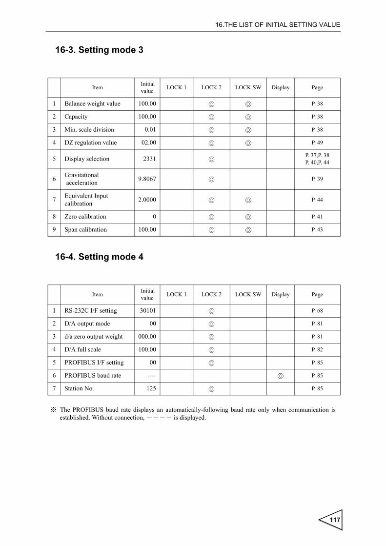
16.THE LIST OF INITIAL SETTING VALUE
16-3. Setting mode 3
16-4. Setting mode 4
Item Initial value LOCK 1 LOCK 2 LOCK SW Display Page
1 Balance weight value 100.00 ◎ ◎ P. 38
2 Capacity 100.00 ◎ ◎ P. 38
3 Min. scale division 0.01 ◎ ◎ P. 38
4 DZ regulation value 02.00 ◎ ◎ P. 49
5 Display selection 2331 ◎P. 37,P. 38P. 40,P. 44
6 Gravitational acceleration 9.8067 ◎ P. 39
7 Equivalent Input calibration 2.0000 ◎ ◎ P. 44
8 Zero calibration 0 ◎ ◎ P. 41
9 Span calibration 100.00 ◎ ◎ P. 43
Item Initial value LOCK 1 LOCK 2 LOCK SW Display Page
1 RS-232C I/F setting 30101 ◎ P. 68
2 D/A output mode 00 ◎ P. 81
3 d/a zero output weight 000.00 ◎ P. 81
4 D/A full scale 100.00 ◎ P. 82
5 PROFIBUS I/F setting 00 ◎ P. 85
6 PROFIBUS baud rate ---- ◎ P. 85
7 Station No. 125 ◎ P. 85
※ The PROFIBUS baud rate displays an automatically-following baud rate only when communication is established. Without connection, ---- is displayed.
117

17.STATEMENT OF CONFORMATION TO EC DIRECTIVES
17.STATEMENT OF CONFORMATION TO EC DIRECTIVES
※ The F741-C is a CE-conforming product. Please follow the following instructions
when you use it.
Unipulse F741-C weighing controller conforms to The EC Directives (based on
Council of the European Communities), and is allowed to affix CE mark on it.
・Lower voltage directives EN61010-1
・EMC directives EN61326-1
The following notice must be observed when you install F741-C unit.
1. Since F741-C is defined as an open type (unit to be fixed or built-in), it must
be
fixed or bolted to frame or solid board securely.
2. The power cable attached to this product as standard equipment can be used in the
AC100V power supply in Japan. (Official ratings voltage AC125V)
Please use the power cable authorized in the country when you use this product
outside Japan.
3. Use shielded cable for connection with components other than power supply,
such as load cell, input/output signals and optional device.
Installation category II Pollution degree 2
EN55011,EN61000-4-2,EN61000-4-3,EN61000-4-4 EN61000-4-5,EN61000-4-6,EN61000-4-8 EN61000-4-11,EN61000-3-2,EN61000-3-3
Notice
Combined use of F741-C and lightning surge protector conforms to EN61000-4-5 of EMC directives. (lightning surge immunity)
118

17.STATEMENT OF CONFORMATION TO EC DIRECTIVES
17-1. Connection of lightning serge protect
To take measures against lightning surge, install a lightning surge protector .
The F741-C main body conforms to EMC directive EN61000-4-5 (lightning surge
immunity) in combination with the lightning surge protect.
● Lightning surge protector[MAINTRAB MNT-1D]
No lightning surge protector [MAINTRAB MNT-1D] is included as a standard.Please
use the power cable authorized in the country when you use this product outside Japan.
Before purchasing it, check the plug shape/voltage, which differs with countries and
regions.
It is optionally available (TSU02) in combination with a 250V AC high-voltage cable in
EU outlet form (See below: Standard product in Europe). For details, contact our sales
department.
F741-Clightning surge protector
*“MAINTRAB MNT-1D” is trademark of Phoenix Contact, Germany
CAAC3P-CEE7/7-B2 : CEE7/7 Plug cable(2m)
119