Operation Manual DILA Electronic control (Version 1.2) · 23 APPENDIX J: BAKING PROGRAM FORM 65 ......
69
English Version 1.2 Art.: 9122961 START P2 P5 P3 P6 P1 P4 START P2 P5 P3 P6 P1 P4
-
Upload
truongnhan -
Category
Documents
-
view
214 -
download
0
Transcript of Operation Manual DILA Electronic control (Version 1.2) · 23 APPENDIX J: BAKING PROGRAM FORM 65 ......
English
Version 1.2
Art.: 9122961
START
P2
P5
P3
P6
P1
P4
l o wh i gh
°C / % r H
O K
START
P2
P5
P3
P6
P1
P4
l o wh i gh
°C / % rH
O K
TZ 05.04.2007 V1 / REL02 Print two sides
Dresdener Strasse 88 D-02625 Bautzen
Telephone: +49 (0) 3591 / 360-0
Fax.: +49 (0) 3591 / 360-140
Hotline for emergencies during non-business hours: +49 (0) 170 / 2236000
E-mail: [email protected]: www.debag.com
Deutsche Backofenbau GmbH +49 / (0)3591/360-0
FOREWORD The information compiled in this manual is given to you and your staff for easier use and operation of your new DiLa-type DEBAG bake-off oven. Please read this manual carefully and make sure the instructions and requirements are respected all the time. This is imperative to ensure smooth operation, permanent availability and a long service life of the bake-off oven. Several passages in this manual refer to optional extras (proofer, exhaust vapour condenser etc.) and are identified accordingly. If your DiLa bake-off oven is not equipped with such optional variants, the relevant information is of no importance for you. If the oven was delivered with special default pre-settings deviating from standard oven configuration according to your requests, it is possible that some of the information contained in this manual is no longer valid. In such case, please refer to the extra information & instruction sheets added to the man-ual. This operation manual has been prepared very carefully. But we cannot rule out the possibility of any errors in texts or pictures. DEBAG Deutsche Backofenbau GmbH cannot accept any judicial responsi-bility or any liability whatsoever for any erroneous statements or their consequences. We would be grateful if you could help us by indicating any mistakes or errors. This manual is subject to change in the interest of optical appearance, technical progress and quality improvement.
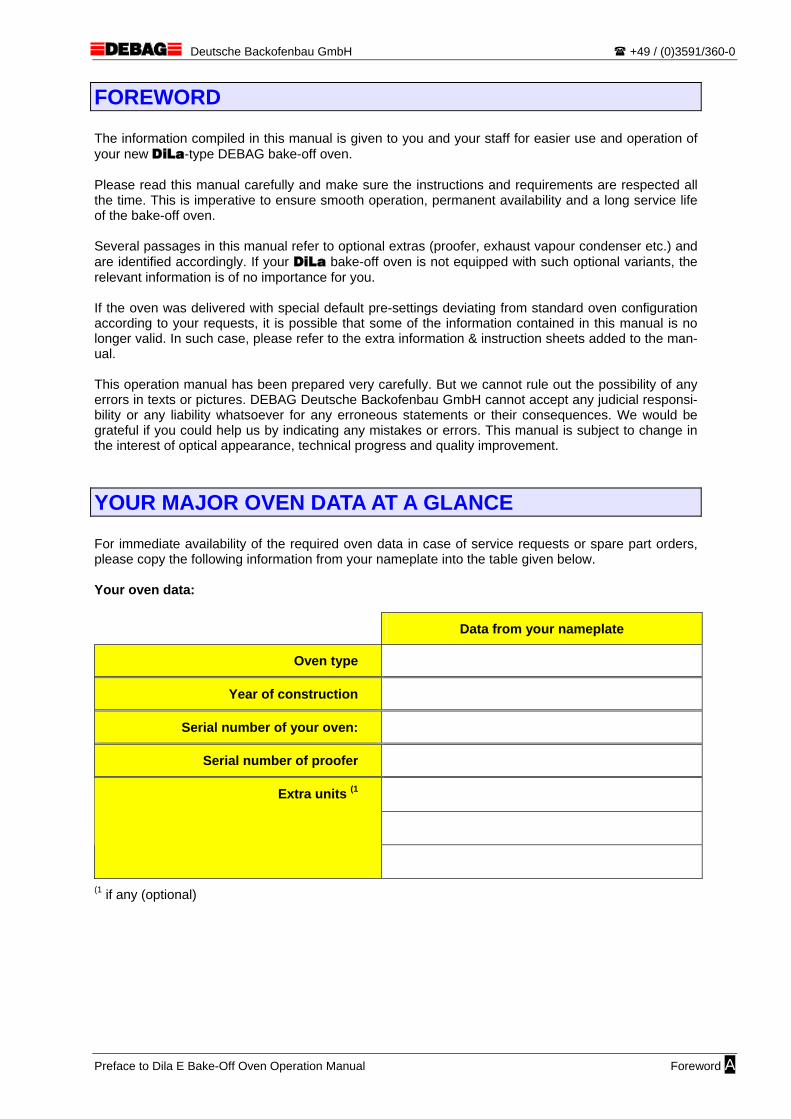
YOUR MAJOR OVEN DATA AT A GLANCE For immediate availability of the required oven data in case of service requests or spare part orders, please copy the following information from your nameplate into the table given below. Your oven data:
Data from your nameplate
Oven type
Year of construction
Serial number of your oven:
Serial number of proofer
Extra units (1
(1 if any (optional)
Preface to Dila E Bake-Off Oven Operation Manual Foreword A
Deutsche Backofenbau GmbH +49 / (0)3591/360-0
1 CONTENTS
page
FOREWORD A
YOUR MAJOR OVEN DATA AT A GLANCE A
1 CONTENTS 1
2 SAFETY INSTRUCTIONS 3 2.1 SYMBOLS 3 2.2 GENERAL INSTRUCTIONS 4 2.3 INTENDED USE 4 2.4 SAFETY AT WORK AND HEALTH PROTECTION 5 2.5 WARRANTY AND LIABILITY 7
3 OVEN CONSTRUCTION AND BAKING PRINCIPLE 8
4 TECHNICAL DATA EXTRACT 9
5 PRECOMMISSIONING INFORMATION 10 5.1 OVEN CONNECTIONS AND OPERATOR CONTROLS 10 5.2 PLACE OF INSTALLATION 11 5.3 SUBSTRUCTURE REQUIREMENTS 11 5.4 HANDLING AND INSTALLATION 12 5.5 ELECTRICAL CONNECTION 12 5.6 WATER CONNECTION 13 5.7 CONDENSATE DISCHARGE 14 5.8 EXHAUST 14 5.9 INITIAL OPERATION 16
6 CONTROL PANEL 17 6.1 PANEL LAYOUT 17 6.2 DESCRIPTION OF PANEL CONTROLS 18
7 NORMAL BAKING OPERATION 22 7.1 BAKING START 22 7.2 PREPARATION OF DOUGHPIECES 22 7.3 SETTING THE BAKING TIME AND BAKING TEMPERATURE” (MANUAL MODE) 23 7.4 BAKING PROGRAM & OVEN LOAD SELECTION (PROGRAM MODE) 24 7.5 LOADING THE OVEN 25 7.6 BAKING 26 7.7 UNLOADING THE OVEN 27 7.8 END OF BAKING 28
8 SPECIAL FUNCTIONS 29 8.1 STANDBY LOW-ENERGY MODE 29 8.2 AUTOMATIC OFF FUNCTION 29
9 CLEANING THE OVEN 30
10 MAINTENANCE OF THE OVEN 32 10.1 HOW TO REPLACE A DEFECTIVE OVEN LAMP 32
11 PROGRAMMING THE BAKING PROGRAMS 33
12 INFORMATION MESSAGES 35
13 TROUBLESHOOTING FOR OVEN AND EXTRA UNITS 37
Page 1 Bake-Off Oven • DiLa E Control • Operation Manual

Deutsche Backofenbau GmbH +49 / (0)3591/360-0
page
14 APPENDIX A: DECLARATION OF CONFORMITY 42
15 APPENDIX B: BAKING TIME COUNT-DOWN DISPLAY 44
16 APPENDIX C: MULTICOLOUR SCROLLING TEXT DISPLAY 46
17 APPENDIX D: PROOFER 48 17.1 CONSTRUCTION OF THE PROOFER 48 17.2 PRECOMMISSIONING INFORMATION 49 17.3 HOW TO VIEW AND ADJUST PROOFING VALUES 50 17.4 PROOFER OPERATING INSTRUCTIONS 51
18 APPENDIX E: WATER TANK 52 18.1 CONSTRUCTION OF BASE CABINET WITH WATER TANK 52 18.2 PRECOMMISSIONING INFORMATION 53 18.3 OPERATING INSTRUCTIONS 54
19 APPENDIX F: DOUBLE OVENS 56 19.1 PRECOMMISSIONING INFORMATION 56 19.2 OPERATING INSTRUCTIONS 57
20 APPENDIX G: OVEN PARAMETERS (FOR EXPERTS ONLY) 58
21 APPENDIX H: AUTOMATIC START FUNCTION 60 21.1 ACTIVITATION OF THE AUTOMATIC START FUNCTION 60 21.2 SETTING THE CURRENT TIME 61 21.3 PROGRAMMING THE START TIMES 62 21.4 SKIP FUNCTION 63
22 APPENDIX I: PROGRAM EXAMPLES 64
23 APPENDIX J: BAKING PROGRAM FORM 65
Bake-Off Oven • DiLa E Control • Operation Manual Page 2
Deutsche Backofenbau GmbH +49 / (0)3591/360-0
2 SAFETY INSTRUCTIONS
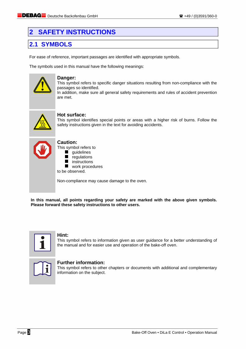
2.1 SYMBOLS For ease of reference, important passages are identified with appropriate symbols. The symbols used in this manual have the following meanings:
Danger: This symbol refers to specific danger situations resulting from non-compliance with the passages so identified. In addition, make sure all general safety requirements and rules of accident prevention are met.
Hot surface: This symbol identifies special points or areas with a higher risk of burns. Follow the safety instructions given in the text for avoiding accidents.
Caution: This symbol refers to
guidelines regulations instructions work procedures
to be observed. Non-compliance may cause damage to the oven.
In this manual, all points regarding your safety are marked with the above given symbols. Please forward these safety instructions to other users.
Hint: This symbol refers to information given as user guidance for a better understanding of the manual and for easier use and operation of the bake-off oven.
Further information: This symbol refers to other chapters or documents with additional and complementary information on the subject.
Page 3 Bake-Off Oven • DiLa E Control • Operation Manual
Deutsche Backofenbau GmbH +49 / (0)3591/360-0
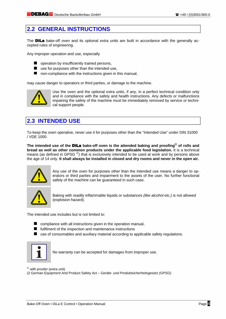
2.2 GENERAL INSTRUCTIONS The DiLa bake-off oven and its optional extra units are built in accordance with the generally ac-cepted rules of engineering. Any improper operation and use, especially
operation by insufficiently trained persons, use for purposes other than the intended use, non-compliance with the instructions given in this manual,
may cause danger to operators or third parties, or damage to the machine.
Use the oven and the optional extra units, if any, in a perfect technical condition only and in compliance with the safety and health instructions. Any defects or malfunctions impairing the safety of the machine must be immediately removed by service or techni-cal support people.
2.3 INTENDED USE To keep the oven operative, never use it for purposes other than the “Intended Use” under DIN 31000 / VDE 1000. The intended use of the DiLa bake-off oven is the attended baking and proofing(1 of rolls and bread as well as other common products under the applicable food legislation. It is a technical means (as defined in GPSG (2) that is exclusively intended to be used at work and by persons above the age of 14 only. It shall always be installed in closed and dry rooms and never in the open air.
Any use of the oven for purposes other than the intended use means a danger to op-erators or third parties and impairment to the assets of the user. No further functional safety of the machine can be guaranteed in such case.
Baking with readily inflammable liquids or substances (like alcohol etc.) is not allowed (explosion hazard).
The intended use includes but is not limited to:
compliance with all instructions given in the operation manual, fulfilment of the inspection and maintenance instructions use of consumables and auxiliary material according to applicable safety regulations.
No warranty can be accepted for damages from improper use.
(1 with proofer (extra unit) (2 German Equipment And Product Safety Act – Geräte- und Produktsicherheitsgesetz (GPSG)
Bake-Off Oven • DiLa E Control • Operation Manual Page 4
Deutsche Backofenbau GmbH +49 / (0)3591/360-0
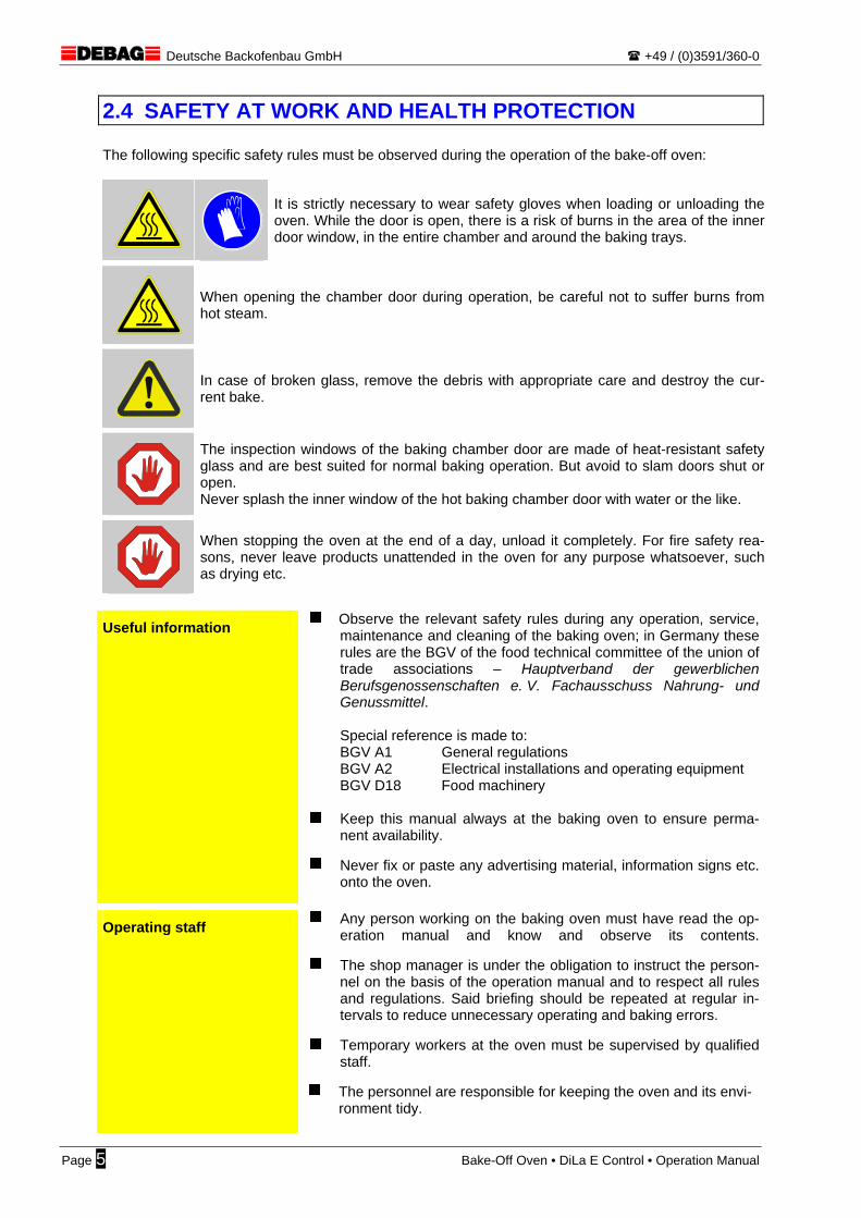
2.4 SAFETY AT WORK AND HEALTH PROTECTION The following specific safety rules must be observed during the operation of the bake-off oven:
It is strictly necessary to wear safety gloves when loading or unloading the oven. While the door is open, there is a risk of burns in the area of the inner door window, in the entire chamber and around the baking trays.
When opening the chamber door during operation, be careful not to suffer burns from hot steam.
In case of broken glass, remove the debris with appropriate care and destroy the cur-rent bake.
The inspection windows of the baking chamber door are made of heat-resistant safety glass and are best suited for normal baking operation. But avoid to slam doors shut or open. Never splash the inner window of the hot baking chamber door with water or the like.
When stopping the oven at the end of a day, unload it completely. For fire safety rea-sons, never leave products unattended in the oven for any purpose whatsoever, such as drying etc.
Useful information Observe the relevant safety rules during any operation, service, maintenance and cleaning of the baking oven; in Germany these rules are the BGV of the food technical committee of the union of trade associations – Hauptverband der gewerblichen Berufsgenossenschaften e. V. Fachausschuss Nahrung- und Genussmittel.
Special reference is made to: BGV A1 General regulations BGV A2 Electrical installations and operating equipment BGV D18 Food machinery
Keep this manual always at the baking oven to ensure perma-
nent availability.
Never fix or paste any advertising material, information signs etc. onto the oven.
Operating staff Any person working on the baking oven must have read the op-eration manual and know and observe its contents.
The shop manager is under the obligation to instruct the person-nel on the basis of the operation manual and to respect all rules and regulations. Said briefing should be repeated at regular in-tervals to reduce unnecessary operating and baking errors.
Temporary workers at the oven must be supervised by qualified
staff.
The personnel are responsible for keeping the oven and its envi-ronment tidy.
Page 5 Bake-Off Oven • DiLa E Control • Operation Manual

Deutsche Backofenbau GmbH +49 / (0)3591/360-0
Safety appliances The safety appliances of the bake-off oven are: the door switch, the overtemperature cut-out in the baking chamber and in the ex-ternal condenser (option), as well as the fan motor thermocon-tacts. The extra proofer is protected by an overtemperature de-tector.
Make sure the function of said appliances is never impaired or manipulated !
Make sure there is always free and direct access to the master
switch of the building or the mains connector (EMERGENCY STOP function).
Control system The control system shall be operated by authorized personnel only.
Humidity & moisture Protect all parts of the electrical equipment from humidity, mois-ture and dust.
Never use water jetters, high-pressure steam cleaners or the like
for cleaning the bake-off oven and its extra units.
Protect the oven from precipitation water (rain, snow) during unloading and handling operations (delivery on site, internal transfers).
Care & maintenance Respect the specified maintenance intervals.
Always disconnect the oven prior to any maintenance work. Pull the power plug.
Make sure maintenance work is always performed by qualified
people in compliance with the safety regulations.
Any conversions, modifications or structural changes of the oven shall require the prior written approval of DEBAG.
In case of repair, never use spare parts other than genuine DE-
BAG parts.
After maintenance and repair, restore all safety conditions that may have been cancelled or reduced for certain operations.
To change defective lamps of the oven lighting, make sure the
oven is cold and disconnected from the power supply.
Cleaning Prior to any cleaning work, make sure the bake-off oven has cooled down and is disconnected from the power supply. Pull the power plug.
Never use water jetters, high-pressure steam cleaners or the like for cleaning the bake-off oven and its extra units.
Bake-Off Oven • DiLa E Control • Operation Manual Page 6
Deutsche Backofenbau GmbH +49 / (0)3591/360-0
2.5 WARRANTY AND LIABILITY Warranty and liability are exclusively governed by our standard terms and conditions. No warranty and liability claims can be accepted in case of personal injury or material damage attributable to any of the following causes including but not limited to:
Improper use of the machine and of its extra equipment or use for purposes other than the in-tended use.
Improper start-up, operation and care of the oven.
Operation of the oven and of any extra unit with defective or non-operative safety appliances (door switches, overtemperature cut-outs, fan motor thermocontacts).
Structural modifications of the oven and of any extra unit, unless with the written consent of DEBAG.
Non-compliance with the requirements, instructions and information given in the operation manual.
Improper repair work.
Use of parts other than genuine DEBAG spare parts.
Improper electrical installation of the oven feeder (overvoltages, undervoltages, interference frequencies, no N-conductor etc.)
Water damage from customer stop valves left open in the water feed line to the bake-off oven and its extra equipment (outside business hours).
Damage to the oven and to any accessory equipment, or poor baking quality, from calcifica-tion.
Unattended drying of products in the baking chamber (whether or not the oven is switched off).
Page 7 Bake-Off Oven • DiLa E Control • Operation Manual

Deutsche Backofenbau GmbH +49 / (0)3591/360-0
3 OVEN CONSTRUCTION AND BAKING PRINCIPLE The DiLa bake-off oven uses an air circulation system. An alternating radial-flow fan housed in the rear panel of the oven conveys the air via the ring heater at a high air velocity evenly to the bake. Schematic drawing of the bake-off oven (DiLa 5):
Burning hazardduring baking operation
Fan impeller(reversing)
Rear wall(removable)
Limiter sensor(on rear wall)
Heatingelement
InsulationDoor rubbermoulding
Door interlock(option)
Door lock
DiLa electroniccontrol
Temperature sensor(in rear wall)
Rubber feet(vertically adjustable)
Externalsteaming(option)
Roundedcorners
Internalspraying(option)
Baking tray supports(removable)
START
P2
P5
P3
P6
P1
P4
lowhigh
°C / %rH
OK
The oven features the fully electronic DiLa E control system. The E-control system has been devel-oped for ease of operation in the manual mode. However, it is possible in case of need to store fre-quently recurring bakes as complete automatic baking program (program mode). All functions of the oven and its extra units are controlled by this electronic system. The DiLa E -control has the following functional features:
manual baking operation mode, setting of baking temperature and baking time
automatic operation according to programmed bake parameters (program mode)
program memory for storage of 6 freely programmable baking programs
pre-wired for a LED count-down display
controls can be coupled in double oven applications
integrated automatic start function with automatic summer/winter time changeover
standby function and automatic stop function for energy cost savings
optional steam generation by a simple water spray system for fan impellers, or powerful exter-nal high-performance steaming system
optional proofer control with automatic air conditioning (temperature/humidity)
optional water tank with level monitoring
For further information on oven construction, also refer to item “5.1 – Oven connections and operator controls” (on page 10) and to the specific dimension drawings and type sheets.
Bake-Off Oven • DiLa E Control • Operation Manual Page 8
Deutsche Backofenbau GmbH +49 / (0)3591/360-0
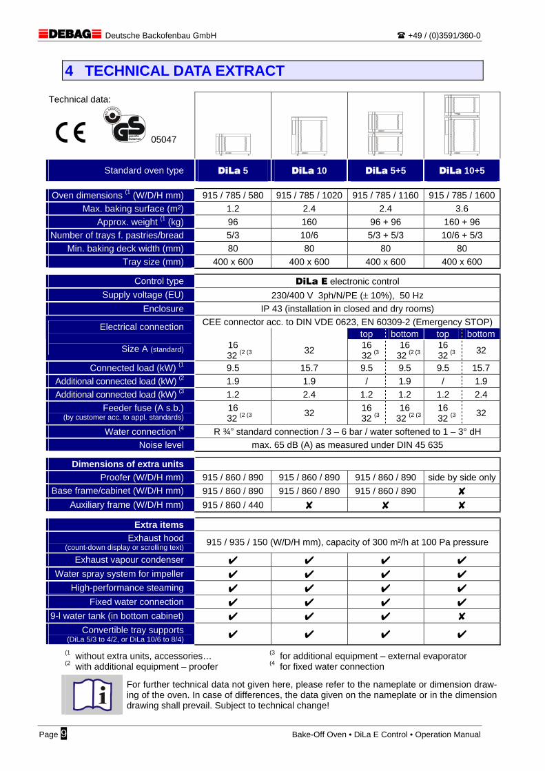
4 TECHNICAL DATA EXTRACT
Technical data:
05047
Standard oven type DiLa 5 DiLa 10 DiLa 5+5 DiLa 10+5
Oven dimensions (1 (W/D/H mm) 915 / 785 / 580 915 / 785 / 1020 915 / 785 / 1160 915 / 785 / 1600Max. baking surface (m²) 1.2 2.4 2.4 3.6
Approx. weight (1 (kg) 96 160 96 + 96 160 + 96 Number of trays f. pastries/bread 5/3 10/6 5/3 + 5/3 10/6 + 5/3
Min. baking deck width (mm) 80 80 80 80 Tray size (mm) 400 x 600 400 x 600 400 x 600 400 x 600
Control type DiLa E electronic control Supply voltage (EU) 230/400 V 3ph/N/PE (± 10%), 50 Hz
Enclosure IP 43 (installation in closed and dry rooms) CEE connector acc. to DIN VDE 0623, EN 60309-2 (Emergency STOP)
top bottom top bottomElectrical connection
Size A (standard) 16
32 (2 (3 32 16 32 (3
16 32 (2 (3
16 32 (3 32
Connected load (kW) (1 9.5 15.7 9.5 9.5 9.5 15.7 Additional connected load (kW) (2 1.9 1.9 / 1.9 / 1.9 Additional connected load (kW) (3 1.2 2.4 1.2 1.2 1.2 2.4
Feeder fuse (A s.b.) (by customer acc. to appl. standards)
16 32 (2 (3 32 16
32 (316
32 (2 (316
32 (3 32
Water connection (4 R ¾” standard connection / 3 – 6 bar / water softened to 1 – 3° dH Noise level max. 65 dB (A) as measured under DIN 45 635
Dimensions of extra units Proofer (W/D/H mm) 915 / 860 / 890 915 / 860 / 890 915 / 860 / 890 side by side only
Base frame/cabinet (W/D/H mm) 915 / 860 / 890 915 / 860 / 890 915 / 860 / 890 Y Auxiliary frame (W/D/H mm) 915 / 860 / 440 Y Y Y
Extra items Exhaust hood
(count-down display or scrolling text) 915 / 935 / 150 (W/D/H mm), capacity of 300 m²/h at 100 Pa pressure
Exhaust vapour condenser U U U U Water spray system for impeller U U U U
High-performance steaming U U U U Fixed water connection U U U U
9-l water tank (in bottom cabinet) U U U Y Convertible tray supports
(DiLa 5/3 to 4/2, or DiLa 10/6 to 8/4) U U U U (1 without extra units, accessories… (2 with additional equipment – proofer
(3 for additional equipment – external evaporator
(4 for fixed water connection
For further technical data not given here, please refer to the nameplate or dimension draw-ing of the oven. In case of differences, the data given on the nameplate or in the dimension drawing shall prevail. Subject to technical change!
Page 9 Bake-Off Oven • DiLa E Control • Operation Manual

Deutsche Backofenbau GmbH +49 / (0)3591/360-0
5 PRECOMMISSIONING INFORMATION
5.1 OVEN CONNECTIONS AND OPERATOR CONTROLS Front view of the DiLa 5 oven.
START
P2
P5
P3
P6
P1
P4
lowhigh
°C / %rH
OK
Rear view of the DiLa 5 oven.
Rear wallpanelling
Baking chamberovertemperature limiter
High-efficiency steamingovertemperature limiter
(option)
Condensation waterdrain hose, 3/4”
(approx. 2 m)
Vapour exhaustwith hood
(150 mm ID)
Vapour exhaust without exhaust hood(80 mm ID)
Control boxwith vents(do not cover!)
Remaining baking time display connection cable
Data interface RS485
Mains feeder cable with CEE plug
(approx. 4 m)
Steaming damper
Steaming damperlifting magnet(option)
Water connection, R3/4”(option)
Suction hose and sensorconnection to water tank(option)
Exhaust hood(option)
with integratedexhaust steam condenser
(option)
Cowl ventilator
Exhaust fanconnection
For ovens with left-handed door stops, the control cubicle is installed on the oven side opposite to that shown in the drawing.
The construction of a DiLa 10 bake-off oven is similar to the above pictures, but the height dimensions are different (dimension (1 ).
Bake-Off Oven • DiLa E Control • Operation Manual Page 10

Deutsche Backofenbau GmbH +49 / (0)3591/360-0
5.2 PLACE OF INSTALLATION The DiLa bake-off oven must be installed in a truly horizontal and stable position using a water level. The place of installation must be in a closed and dry room. Outdoor installation is prohibited.
When setting up the bake-off oven, make sure neither the oven nor its feed and dis-charge lines can cause damage to building structures from excessive heat. Always take care to keep safe distances from or provide appropriate insulations close to inflammable parts or other building equipment. Compliance with applicable fire protection rules & regulations is compulsory. In case of doubt, consult your installer or your property owner.
When using a substructure, make sure it meets the requirements specified in the chap-ter “5.3 – Substructure requirements“ (page below).
5.3 SUBSTRUCTURE REQUIREMENTS
DEBAG offers suitable base frames, base cabinets or proofers as ‘genuine part’ accessories for the DiLa bake-off oven. Please contact our sales department. When using a base frame or a proofer from other manufacturers, make sure the DiLa bake-off oven meets the following installation requirements:
Install the substructure at the given location in a truly horizontal position using a water level and fix it safely. Use appropriate means to protect the substructure from slipping or moving (braked castors or the like).
The substructure must have the proper stability and load carrying capacity according to the Technical Data (weight of the delivered oven type) and in all operating statuses.
Make sure the bake-off oven stands safely with all 4 rubber feet on the substructure and pro-tect it reliably from slipping. The genuine DEBAG substructures contain a centring profile in the rear of the top. Make sure the rear rubber feet of the oven fit the profile section.
The height of the substructure should be chosen such as to allow also shorter people to oper-ate the oven. Where possible, take care not to exceed a working height of 160 cm for the up-permost baking tray (not always feasible).
Substructure dimensions:
715
mm
915 mm
Top view of baseframe
The required load-bearing capacity
must be ensured in an area within approx.
200 mm from the edge!
Operator control side
Bea
ring
area
Substructure design solutions must be submitted to DEBAG prior to use. They may not be used until they are validated in writing by DEBAG. Operate the bake-off oven only if it is in good condition and properly secured on the substructure.
For ovens having a water tank, never use any substructure other than a special base cabinet made by DEBAG. In such case, it is not possible to use substructures from other sources.
Page 11 Bake-Off Oven • DiLa E Control • Operation Manual

Deutsche Backofenbau GmbH +49 / (0)3591/360-0
5.4 HANDLING AND INSTALLATION The bake-off oven is usually shipped on a special wooden pallet. This ensures smooth and safe han-dling with fork or platform lift trucks. Install the bake-off oven on its substructure (base frame, base cabinet, proofer etc.):
Place the oven with its pallet in front of the substructure and align it properly for installation. Remove the transport safety devices (wooden strips, strap retainers etc.). Check the substructure according to 5.3 (on page 11 ) and protect it from slipping. Lift the pallet and the oven up to the substructure level using a scissor lift truck (1-metre lift) or
a fork lift truck. Pull/draw the oven off the wooden pallet over to the base support (at least 2 persons). Fix the oven properly to the substructure.
When lifting or shifting the oven, make sure the lifting equipment is in a stable position and the forks of the lift are properly engaged!
You will find further information in the documents regarding the proofer (Chapter 17.1 – on page 48) or the base cabinet with water tank (Chapter 18.1 – on page 52).
5.5 ELECTRICAL CONNECTION The electrical connection of the DiLa E bake-off oven in its standard version is made via a standard 16A or 32A CEE plug-in connector, depending on the oven type and equipment. The building installa-tions such as feeder, feeder fusing and socket outlet must be executed in compliance with the specifi-cations given in the Technical Oven Data section. Should no plug-in connector be used for the electrical connection, it is imperative to provide an all-pole disconnecting master switch near the oven (EMERGENCY STOP).
Only a duly qualified electrician is authorized to lay, install and fuse the building’s feeder (VDE 0105). Take care to observe the VDE regulations (VDE 0100) as well as any regulations of your local power supply company. Also observe any relevant national standards.
As the connector also serves disconnection purposes (Emergency Stop), the plug must be freely accessible at any time. The same applies to the possible use of a master switch. The operating staff must be familiar with the location of the plug-in connector or master switch.
The sense of rotation of the feeder’s rotating field is of no importance for proper opera-tion of the DiLa bake-off oven.
You are urgently recommended to use a 3-pole disconnecting circuit breaker or (and) a residual current-operated circuit breaker (FI).
You can find binding information on the oven data on the nameplate or in the dimen-sional drawing of the oven, or a summary table in Chapter 4 – “Technical Data” (on page 9). In case of doubt, contact the service department of DEBAG.
Bake-Off Oven • DiLa E Control • Operation Manual Page 12

Deutsche Backofenbau GmbH +49 / (0)3591/360-0
5.6 WATER CONNECTION 5.6.1 Ovens with fixed water connection An R3/4“ cold water connection with a suitable stop valve is to be provided by the customer in close vicinity of the DiLa E bake-off oven (max. 1 m). Connect the oven using the grey, pressure-proof wa-ter connection hose (washing machine hose), which is enclosed in the delivery. Attach the hose to the water connection of the oven (on page 10). The feed water pressure shall be between 3 and 6 bar. A pressure reducer is required for water pres-sures above 6 bar. Always use water softened to 1-3° dH to minimise calcification of the injection lines, the inner oven and the steam generator (option). In areas with higher water hardness, it is imperative to use an ap-propriate decalcification or filter plant.
To avoid water damage, make sure the stop valve of the building is closed during non-business hours.
For hygienic reasons, it is not allowed to connect the oven to water supplies other than the public drinking water network. It is strictly necessary to meet the required water quality to avoid accelerated obsolescence of the oven.
Take care to lay the grey water connection hose so as to avoid sharp bends and con-tact with sharp edges. The distance between the oven and the water connection point should be chosen such that the hose is free from tensile stress. For built-in ovens, make sure the hose is long enough to allow for easy maintenance and service (by pulling the oven to the front).
Never lay the water hose directly along hot oven parts such as the exhaust pipe and exhaust damper.
For appropriate water treatment, you are recommended to use the activated carbon filter system “BRITTA Aqua Quell 33” (new: “Purity 300”). This filter size is absolutely sufficient for normal use of the DiLa oven. In special cases, the exact filter size must be determined from the water demand and the local water quality. To avoid damage to the oven, never attempt any full decarbonisation of the tap water (approx. 1 mm bypass). The BRITTA filter system should be ordered as accessory item from DEBAG together with the new DiLa oven. The installation, adjustment and annual inspection of the filter system will also be performed by DEBAG service technicians. For more information, please contact your local DEBAG consultant or our sales depart-ment.
DEGAB will not accept any warranty or liability for any damage incurred by the oven and its extra units, or any impairment of the baking quality, as a result of calcification.
When using a feed water softener or filter system, read and strictly follow the relevant operating instructions and especially the maintenance instructions.
5.6.2 Ovens with water tank No connection to the public drinking water distribution system is required for ovens having their own water tanks. Water is supplied via a reservoir housed by a base cabinet. Also refer to Chapter “18 – Appendix: Water tank” (on page 52).
Page 13 Bake-Off Oven • DiLa E Control • Operation Manual
Deutsche Backofenbau GmbH +49 / (0)3591/360-0
5.7 CONDENSATE DISCHARGE The water obtained during bakes from the exhaust vapour condenser (option), the external evaporator (option) and the exhaust pipe is collected behind the oven and is to be passed into a suitable heat-resistant collecting bin (e.g. a water bucket etc.) or floor drain (gully hole) (on page 10).
The condensate flow especially during a bake can be very hot (up to 90°C). Therefore, never empty the collecting bin during a bake and never reach into the outgoing conden-sate flow – risk of scalding.
Check the water level of the collecting bin prior to each baking run. Empty the bin at least once every day to meet the hygienic requirements.
For steamed bakes, but also for frequent bakes without steaming, it may be necessary to empty the collecting bin several times a day.
If possible under local conditions, the condensed water can be discharged directly into a heat-resistant drain. Then it is possible to do without the repeated changes of the col-lecting bin. For built-in ovens, make sure the hose is long enough to allow for easy maintenance and service (by pulling the oven to the front). It is imperative to prevent the discharged water from flowing out of building drain back into the collecting bin or oven (observe slopes and backpressures).
For convenient access, especially for built-in ovens, the collecting bin should be inte-grated in the base frame.
In ovens without steaming, slime deposits may form in the drain hoses and the conden-sate bin. Monthly cleaning is recommended.
5.8 EXHAUST
5.8.1 Ovens without steaming Since this model of the DiLa E bake-off oven has no extra steaming function and since most of the moist exit air passing through the exhaust damper (unloading loss) condenses in the small condensa-tion pipe, the residual exit air can normally be discharged without any additional measures into the ambience air of the oven.
In special cases, however, check whether it is necessary to install an additional steam discharge line. Discuss the matter with the property owner.
Bake-Off Oven • DiLa E Control • Operation Manual Page 14

Deutsche Backofenbau GmbH +49 / (0)3591/360-0
5.8.2 Ovens with steaming The moist exhaust vapour from steamed bakes in the DiLa bake-off oven must be passed through a corrosion-proof heat-resistant pipe (ID 80 with exhaust hood ID 150 (on page 10)) into a stack or directly discharged into the atmosphere. The stack must be resistant to condensates and equipped with a steam trap.
Never allow the exhaust vapour from the baking process to enter the room where the oven is located, unless additional measures are taken!
When installing the exhaust pipe, make sure the collecting condensate can run off freely (permanent slope). If this is not the case, a “water pocket” may form and impair the baking quality.
Never attach any external fan or centralized extraction system to the exhaust connec-tion point, because this may impair the baking quality. Where necessary, use draft regu-lation.
When fitting the pipe sections into each other, take care of the direction of condensate backflow to avoid leakage at the joints. Where necessary, seal the pipe joints with a heat-resistant sealant (silicone).
5.8.3 Exhaust vapour condenser Where local conditions do not allow the exhaust vapour to be discharged directly into the atmosphere or into a suitable stack or chimney, an exhaust vapour condenser can be mounted to the oven. This condenser works like an air-cooled heat exchanger and is fully integrated in the exhaust hood. The only discharge from the exhaust vapour condenser is dry air from the baking chamber. Discharge to atmosphere is no longer required. Working mechanism of the condenser:
Humid and hot exhaust air flowingin through baking chamber
Dried and colled air from theexhaust steam condenser Cowl ventilator
Required ventilating space(hatched area)
Cold room air flowing in through steam hood
Min
.30
cm
Bake-off oven
For proper operation of the exhaust vapour condenser it is important to have enough ventilation space (hatched area) above the oven. Never cover or obstruct this region.
The exhaust vapour condenser can be installed at a later stage after clarification of spe-cial structural conditions. Call our service department.
Page 15 Bake-Off Oven • DiLa E Control • Operation Manual
Deutsche Backofenbau GmbH +49 / (0)3591/360-0
5.9 INITIAL OPERATION Install and connect the oven properly according to the previous chapters inclusive of the connections with any optional extra unit. Only then the oven will be ready for operation.
Remove the protective foil from all cover panels prior to the first heating-up of the oven.
Especially during winter time, before starting up the oven in warm and humid rooms, make sure the cold oven shows no further condensation. Never start up the oven until its temperature meets the ambient temperature.
Do not discard the foil, but recycle it.
Prior to its delivery, the oven is thoroughly cleaned and heated by the manufacturer. But for the initial start-up, you are recommended to heat up gain the empty oven under bak-ing program and keep it at this temperature for a period of some 2 hours. This is the time needed for the complete combustion of all cleaning residues. Minor smells and vapours may develop during this phase.
After this initial heating phase, clean the interior of the oven and the inner glass pane of the baking chamber door thoroughly.
Bake-Off Oven • DiLa E Control • Operation Manual Page 16
Deutsche Backofenbau GmbH +49 / (0)3591/360-0
6 CONTROL PANEL
6.1 PANEL LAYOUT
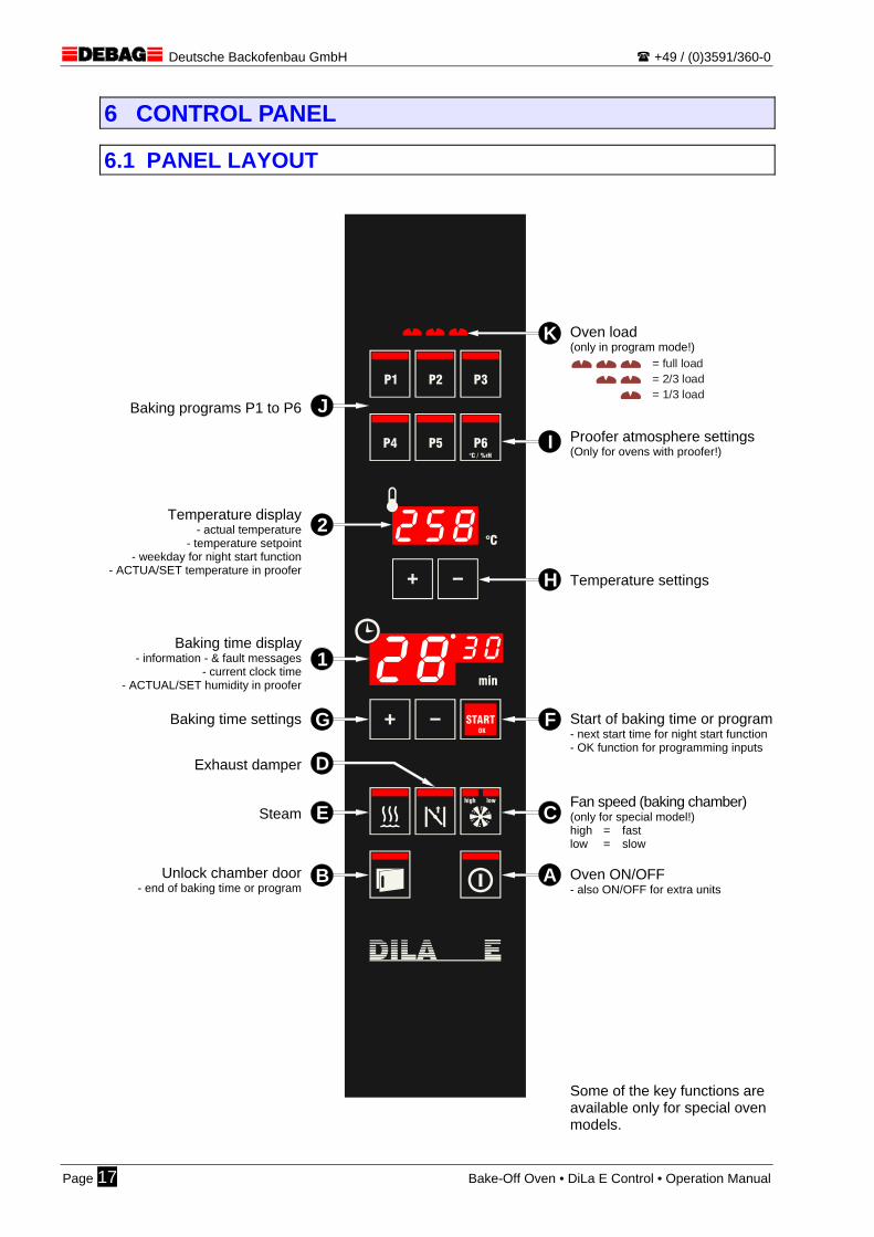
Baking programs P1 to P6
Temperature display - actual temperature
- temperature setpoint - weekday for night start function
- ACTUA/SET temperature in proofer
Baking time display - information - & fault messages
- current clock time - ACTUAL/SET humidity in proofer
Baking time settings
Exhaust damper
Steam
Unlock chamber door - end of baking time or program
START
P2
P5
P3
P6
P1
P4
lowhigh
°C / %rH
OK
B
C
F
H
I
K
A
E
D
G
1
2
J
Oven load (only in program mode!)
= full load= 2/3 load= 1/3 load
Proofer atmosphere settings (Only for ovens with proofer!)
Temperature settings
Start of baking time or program - next start time for night start function - OK function for programming inputs
Fan speed (baking chamber) (only for special model!) high = fast low = slow
Oven ON/OFF - also ON/OFF for extra units Some of the key functions are available only for special oven models.
Page 17 Bake-Off Oven • DiLa E Control • Operation Manual

Deutsche Backofenbau GmbH +49 / (0)3591/360-0
6.2 DESCRIPTION OF PANEL CONTROLS (from the bottom to the top)
A
ON/OFF key Press this key to switch on the oven which will heat up to the set tempera-ture (manual mode) or to the programmed start temperature of the currently active baking program. The key LED lights up. If you push this button while the oven is on and the baking chamber tem-perature is less than 180 °C, the oven will be switched off immediately. In case of higher temperatures in the baking chamber, the fan will continue running until the chamber has cooled down and will then stop automatically (cooling down phase). The cooling down period is indicated by the flashing LED in the key.
To prevent the oven from being inadvertently switched on or off, the key must be pressed for at least 0.5 seconds to respond.
If this key is pressed during a programming operation, the programming function will be cancelled without saving the changes made so far.
If the "Automatic OFF" function is activated, the oven will stop automatically after a certain idle time (on page 29).
A proofer (optional extra) connected with the oven will be switched on or off in parallel with the oven. Also refer to Chapter “17 – Appendix Proofer” (on page 48).
B
OPEN DOOR / END OF BAKING PROGRAM key This key is used to open the chamber door whether the oven is on or off. If the key is pressed at the end of a baking time or of a baking program dur-ing the aeration position (door is slightly ajar but still locked), the baking pro-gram will be stopped and the door released. The key LED flashes rapidly at the end of a baking program. Permanent light means the door is fully open.
When the key is pressed while the oven is on, there may be a small delay until the door actually opens. This time is necessary for slowing down the impeller wheel in the chamber.
The key is locked during steaming.
If the key is actuated during the run of a baking program and the door re-mains open for more than 1 minute, the current program will stop at once.
If the oven is disconnected from the power supply, the only way to open the baking chamber door is to use the emergency unlocking devices underneath the oven.
Chapter “7.1 – Baking Start” (on page 22)“ Chapter “7.7 – Unloading the oven (on page 27)“ Chapter "5.1 – Oven connections and operator controls” (on page 10)“
Bake-Off Oven • DiLa E Control • Operation Manual Page 18

Deutsche Backofenbau GmbH +49 / (0)3591/360-0
lowhigh
C
FAN SPEED key This key is functional only for ovens equipped with this option. When pressed while the oven is ON, this key allows the operative to change between two speed ranges: fast (high) and slow (low). The selected speed range will be used only during the actual baking process. Outside the baking process, the fan always runs at high speed.
The fan speed cannot be changed after the start of any of the baking pro-grams P1 to P6. The oven will always use the speed range defined in the program.
If required, the oven can be adjusted so as to accept speed adjustments also outside a baking process. Please ask our service department.
D
EXHAUST DAMPER key This key is functional only for ovens equipped with this option. When pressed while the oven is ON, this key allows the exhaust damper to be opened or closed.
After a baking program (P1 to P6) is started, the key can also be operated manually, if necessary.
E
STEAM key This key is functional only for ovens equipped with this option. This key is used to give a steam pulse in the baking chamber after the start of a baking run when the baking chamber door is closed. The steam pulse length has been preset by the manufacturer according to the type of steam-ing.
When opening the door of the baking chamber immediately after a steam pulse, be very careful and avoid the escaping hot steam.
For ovens with impeller steam generation (LRB), this key will start the fan in the baking chamber first. So there may be a time lag of about 2 seconds for the steam pulse.
For ovens with a high-performance steam generator (HLB), the key LED will flash when the oven is switched on, until the external evaporator is ready for operation. The oven cannot be started at that point.
After the start of a baking program (P1 to P6), the key can be used for addi-tional manual steam as may be required.
Water amonts per manual or program steam pulse (works setting)
DiLa 5 > impeller steam generation approx. 90 ml (9 ml/sec) DiLa 5 > high-performance steam generator approx. 120 ml (60 ml/sec) DiLa 10 > impeller steam generation approx. 180 ml (18 ml/sec) DiLa 10 > high-performance steam generator approx. 240 ml (120 ml/sec) Hint for experts: The pulse time and thus the pulsed water amount can be adjusted using the oven parameter oP.32 (on page 58).
Page 19 Bake-Off Oven • DiLa E Control • Operation Manual

Deutsche Backofenbau GmbH +49 / (0)3591/360-0
STARTOK
F
Baking time or baking program START / OK function key Once the set baking temperature is reached and the evaporator (option) heated up, the key LED starts flashing to signal that the oven is ready for operation. After the oven is loaded with doughpieces, press this key to start the baking run (time) or the pre-selected baking program. The key shows steady light after the baking time or program has started. In programming operations for baking programs and for changing oven set-tings, this key holds the OK (Save) function.
For so long as the oven is not yet ready for operation (key LED is out, baking chamber or external evaporator still heating up), the baking time or baking program cannot be started. The baking time display 1 shows the message “H2” (or “H8” in case the oven is too hot).
The key is illuminated when the oven has been switched off with the auto-matic start function being active. When this key is pressed, the displays show the next start time 1 (editable) and the next start day 2 .
G
+/– keys for baking time adjustment (manual bakes) When the oven is ON, the keys can be used to view the baking time and, if necessary, adjust it (in 30-sec steps).
When programming baking programs or making oven settings, use the keys to change the value indicated in the baking time display 1 .
1
BAKING TIME display When the oven is powered on, the display shows the set baking time (man-ual mode) or the baking time of the selected baking program (program mode). After the start of a baking run or program, the display indicates the remaining baking time If the oven is powered off with the automatic start function being active, the display will shot the current time or the next start time (when the START key is pressed). Hint messages (H codes) and error messages (E codes) would also appear here.
For oven settings (parameters, automatic start, proofing temp/humidity etc.), the baking time display will indicate the chosen values.
Chapter “Setting the baking time and baking temperature” (on page 23) Chapter “Programming of baking programs (on page 33)" Appendix “Proofer” (on page 48) Appendix “Oven parameters” (on page 58) Appendix “Automatic start” (on page 60)
H
+/– keys for baking temperature adjustment (manual bakes) Press any of the two keys while the oven is ON to view the current tempera-ture setpoint in the temperature display 2 . If pressing any of the keys again within the next 3 seconds during manual operation, you enter the setting mode and can change settings. No change is possible in the program mode.
When programming baking programs or making oven settings, your changes refer to value shown in the temperature display.
Bake-Off Oven • DiLa E Control • Operation Manual Page 20

Deutsche Backofenbau GmbH +49 / (0)3591/360-0
2
TEMPERATURE display While the oven is ON, the display shows the current temperature inside the baking room. Use the +/– keys H to view and change the temperature set-point (see the description there). The display flashes until the oven is ready for operation (indicating too low or too high temperatures in the baking chamber).
When the oven is OFF and the automatic start function active, the display shows the next start day (1=Mo, 2=Tue, 3=Wed, 4=Th, 5=Fr, 6=Sa, 7=Su).
Chapter “Programming of baking programs (on page 33)" Appendix “Proofer” (on page 48) Appendix “Automatic start” (on page 60)
P6°C / %rH
I
BAKING PROGRAM P6 / PROOFING ATMOSPHERE key For ovens without proofer, the P6 key is a normal baking program number key. For ovens with proofer, the P6 key is used to view and vary the current at-mosphere (temperature/humidity) in the proofer. If this key is pressed, the temperature display 2 will show the current proofer temperature and the baking time display 1 will indicate the current humidity in the proofer. Use the associated +/– keys ( G or H ) to view and, if necessary, change set-points.
So there are just 5 baking program numbers available for ovens with proofer.
Appendix “Proofer – How to view and adjust the proofing atmosphere” (on page 50)
P1
J
K
BAKING PROGRAM keys P1 to P6 and OVEN LOAD If none of the baking program keys is illuminated, the oven is in manual mode. Press any of the program keys to enter the program mode. The active pro-gram key is illuminated. The active key can be pressed repeatedly to set the actual oven load (sheet number) and also to exit the program mode.
1. the first touch of an inactive (non-illuminated) baking program key acti-vates the associated baking program at full oven load
2. the second touch of the illuminated baking program key activates the 2/3rd oven load
3. the third touch of the illuminated baking program key activates the 1/3rd oven load
4. the fourth touch of the illuminated baking program key deactivates the key and causes the control system to change back to the manual mode
Holding a program key for some time (3 sec) while the oven is OFF causes the control system to change over into the programming mode and the asso-ciated baking program can be modified or newly programmed.
In the manual mode, the oven load has no function and cannot be adjusted.
Chapter “Baking program and oven load selection (on page 24)" Chapter “Programming of baking programs (on page 33)"
Page 21 Bake-Off Oven • DiLa E Control • Operation Manual
Deutsche Backofenbau GmbH +49 / (0)3591/360-0
7 NORMAL BAKING OPERATION The DiLa E-control system has been developed specifically for manual bakes (manual mode). Man-ual bake implies that all of the processes and operations that are necessary during a baking run are carried out by the oven operator at the right time with the appropriate controls.
Manual bakes require industrial baking knowledge and permanent attention during the baking process. Therefore, some basic training for oven operators is indispensable and crucial for good product quality.
In addition, the DiLa E control offers automated bakes with stored baking programs for frequently recurring baking jobs. The program mode reduces operator inputs to a necessary minimum. All opera-tions during the baking process will be performed at the programmed time automatically by the control system. This guarantees for constant high product qualities.
7.1 BAKING START
To start a bake, first close the door of the baking chamber and then press the ON/OFF button A to turn on the oven. At the same time, the oven lighting goes on and the baking chamber
fan as well as the heat control start operation.
For ovens with a fixed water connection, open the stop valve in the water feed line.
Before starting a bake, make a visual inspection to check the oven for visible damages. Never switch on the oven if its operational condition is not safe. Inform the responsible manager.
Several error & hint messages just appear for 3 seconds in the display when the oven is switched on. The oven will not start until the error display sequence is complete!
Turn on the cold oven at least 15 minutes before starting your bake (at least 30 minutes for ovens with high-performance steam generator). A shorter heat-up period could im-pair the quality of the first bake.
Chapter “Description of panel controls” (on page 18) Chapter “Troubleshooting” (on page 37)"
7.2 PREPARATION OF DOUGHPIECES Prior to the actual baking process and depending on what types of doughpieces you are going to use (prebaked, fresh, frozen), prepare them according to the doughpiece manufacturer’s instructions (by defrosting, proofing etc.) and place them on the baking trays.
For best browned pastry, make sure the doughpieces are not in touch with each other on the tray. Follow the manufacturer’s recommendations as to the number and spacing of the dough pieces. In case of questions, don't hesitate to contact the doughpiece manufacturer or our mas-ter baker.
The normal case for DiLa bake-off ovens with proofer is to proof the doughpieces under automatically controlled temperature and humidity conditions in the proofer.
Bake-Off Oven • DiLa E Control • Operation Manual Page 22

Deutsche Backofenbau GmbH +49 / (0)3591/360-0
The duration of the proofing process and the required atmosphere largely depend on the condition of the doughpieces and are to be defined and permanently checked by the operators.
The DiLa E bake-off oven has no proofing programs and the baking programs have no impact on the proofer. The atmosphere in the proofer cannot be controlled by hand.
To ensure the air conditioning system works properly, take care to open proofer doors just for the minimum time needed for inserting or removing baking trays. Also refer to Chapter “17 – Appendix: Proofer” (on page 48)
7.3 SETTING THE BAKING TIME AND BAKING TEMPERA-TURE” (MANUAL MODE)
Prior to bakes in the manual mode, it is important to check and, if necessary, adjust the baking tem-perature, baking time and fan speed (special item) at the control panel. 1. Set the baking temperature 2. Set the baking time 3. Pre-select the fan speed
(option)
START
lowhigh
OK
H
2
START
lowhigh
OK
1
G
START
lowhigh
OK
C
• Press the temperature keys H
once to view the set baking temperature (setpoint) in the display H .
• Use the +/- keys H to set the new baking temperature.
• After 3 seconds, the display will change back to the actual tem-perature of the baking chamber.
• Use the +/- keys G to set the desired baking time in the time display 1 . The time setting can be varied in 30-second steps.
Option only!
• Press the fan speed key C to set the desired speed range for the baking process.
high = fast / low = slow
Hint: The selected speed range will be used only during the baking process.
The values should be entered several minutes before starting a bake for allowing the oven to adjust itself to the new baking temperature.
Page 23 Bake-Off Oven • DiLa E Control • Operation Manual

Deutsche Backofenbau GmbH +49 / (0)3591/360-0
7.4 BAKING PROGRAM & OVEN LOAD SELECTION (PROGRAM MODE)
When using the program mode, select the desired baking program number and oven load (sheet number) at the oven several minutes before starting the bake.
1. Select the baking program 2. Set the baking load
K
J
K
J
• Press the desired program number P1 to P6
J to activate the baking program stored un-der the chosen number.
• The key will light up with the “full oven” load setting.
• For smaller baking lots, press the active pro-gram key J again to adjust the actual lot size (oven load).
1st touch = full load 2nd touch = 2/3 load 3rd touch = 1/3 load 4th touch = manual mode
Changeovers between baking programs are possible only when the oven has been switched on with no program being started. A vacant program number key (no pro-gram stored) cannot be selected.
Select a new baking program several minutes prior to starting a bake for allowing the oven to adjust itself to the temperature of the new program.
When changing from a program with a high start temperature to a program with a low start temperature, open the door of the baking chamber to shorten the cooling down period.
For ovens with a connected proofer, the P6 program key is reserved for proofer control and cannot be used for a normal baking program.
For ovens with high-performance steam (HLB), the oven will not be ready until the ex-ternal evaporator has heated up (steam key is not flashing).
Bake-Off Oven • DiLa E Control • Operation Manual Page 24
Deutsche Backofenbau GmbH +49 / (0)3591/360-0
7.5 LOADING THE OVEN When the oven has reached the set baking temperature (manual mode) or the start temperature of the selected baking program (program mode), a brief signal will sound with the START key F flashing slowly. Only now, the oven is ready and can be loaded with doughpieces.
The oven must be ready for operation, otherwise it is impossible to activate a program key and start a program. So wait until the oven is ready before inserting doughpieces.
If the oven is too hot, briefly open the door of the baking chamber for better cooling.
For ovens with high-performance steam (HLB), the oven will not be ready until the ex-ternal evaporator has heated up.
Press the OPEN DOOR key B to open the chamber door.
Then insert the baking trays with the prepared doughpieces swiftly into the oven, from the
bottom to the top. In case of reduced oven loads, distribute the trays evenly in the baking chamber.
Close the baking chamber door and press immediately the START key F .
It is absolutely necessary to wear suitable safety gloves when insert-ing the baking trays. While the door is open, there is a risk of burns in the area of the inner door window, in the entire chamber and around the baking trays.
In case of reduced oven loads, distribute the trays evenly in the baking chamber. This is very important for the baking quality, especially for the DiLa 10.
To avoid excessive heat losses, load the oven as swiftly as possible from the bottom to the top and then close the baking chamber door.
To ensure a long service life of the door seals, take care not to hit the rubber profiles with baking trays.
Page 25 Bake-Off Oven • DiLa E Control • Operation Manual

Deutsche Backofenbau GmbH +49 / (0)3591/360-0
7.6 BAKING
7.6.1 Manual baking mode: In the manual mode, all parameter changes and baking operations must be performed manually via the panel controls.
Steam injection is necessary, depending on the type of pastries. Press the steam key to trigger a steam pulse with a defined length. The required number of steam pulses depends on the given product and can be found in the baking instructions.
The exhaust damper (option) must be opened during or at the end of a bake, de-pending on what pastry is baked. The LED in the key shows steady light while the damper is open.
lowhigh
Option only! Where necessary, it is possible to change the fan speed range during a bake.
Where necessary, it is possible to change the baking temperature range during a bake.
When opening the baking chamber door, be careful not to suffer burns from hot steam.
The fan rest function (steady atmosphere) is controlled automatically during steam pulses.
7.6.2 Program mode: After the start of the baking program, all specified parameters are automatically processed in the given order. No further operator actions are required. However, if necessary, the operative can give addi-tional steam pulses or open the exhaust damper.
When opening the baking chamber door, be careful not to suffer burns from hot steam.
In case a baking program is started inadvertently, you can interrupt it by pressing the ON/OFF key A or by opening the door manually with the OPEN DOOR key B . The door must remain open for at least 60 seconds.
It is not possible to change between programs while a baking program is running.
Bake-Off Oven • DiLa E Control • Operation Manual Page 26

Deutsche Backofenbau GmbH +49 / (0)3591/360-0
7.7 UNLOADING THE OVEN At the end of a baking program, the baking chamber door opens automatically into its aeration position (ajar). The OPEN DOOR key B flashes rapidly. In addition, a brief beep sequence will sound every 15 seconds with increasing intensity.
Press the OPEN DOOR key B to terminate the baking program. The chamber door will be unlocked and can be fully opened from its ajar position.
Then the trays with the baked products can be removed (unloaded) from the oven. For cool-
ing down the pastries for some other 5 minutes, insert the trays in appropriate racks. After that, fill the products into the selling containers or the like.
After removing all trays, close immediately the baking chamber door.
If necessary, enter a new baking temperature and baking time (manual mode) or select a
new baking program (program mode) for the next baking job. After a short heat-up time, the oven is back ready for operation after some 3 minutes.
It is absolutely necessary to wear appropriate safety gloves when re-moving the baking trays from the oven. While the door is open, there is a risk of burns in the area of the inner door window, in the entire chamber and around the baking trays.
To avoid excessive heat losses, take care to close again the baking chamber door as quickly as possible also after unloading.
The door can remain closed at the end of the baking time, if so requested by you (oven setting).
Page 27 Bake-Off Oven • DiLa E Control • Operation Manual
Deutsche Backofenbau GmbH +49 / (0)3591/360-0
7.8 END OF BAKING
After the final baking run, the oven must be switched off manually with the ON/OFF key A .
For ovens with a fixed water connection, remember to close the stop valve in the water feed line.
Remove all products from the banking chamber.
When the oven has cooled down, perform the daily cleaning work as specified in the instruc-
tions.
There is a high risk of burns also after the bake-off oven is switched off (tempera-tures above 100 °C in the baking chamber).
When stopping the oven at the end of a day, unload it completely. For fire safety reasons, never leave products unattended in the oven for any purpose whatso-ever, such as drying etc.
In case the oven is switched off with a temperature of more than 180 °C in the baking chamber, the circulating fan will keep running until the temperature falls below this value and will then stop automatically (cooling down phase). The ON/OFF key A flashes.
If the "Automatic OFF" function is activated, the oven will stop automatically after a cer-tain idle time.
In case of ovens with proofer, it is wise to leave the proofer door open over night (ex-cept for a programmed automatic start).
Chapter "8.2 – Automatic OFF function” (on page 29)" Chapter "9 – Cleaning the oven” (on page 30)" Appendix “17.4.1 – Cleaning the proofer“ (on page 51) Appendix “21 – Automatic start function” (on page 60)
Bake-Off Oven • DiLa E Control • Operation Manual Page 28

Deutsche Backofenbau GmbH +49 / (0)3591/360-0
8 SPECIAL FUNCTIONS The DiLa bake-off oven has a series of special functions providing major advantages in terms of op-erator comfort, energy savings and running time management in comparison with similar machines.
8.1 STANDBY LOW-ENERGY MODE If the idle time of the oven exceeds the standby start time setting (default value 30 min) without any button or key being pressed or without any baking program being started, the temperature in the oven will be reduced automatically (default value 130°C). The fan motor in the baking chamber will then start only for re-adjustment of the temperature. Baking time display 1 :
The standby mode can be cancelled and the oven reactivated by pressing the START key F . The oven will be ready for operation within a short time.
The oven cannot enter the standby mode until the end of the first bake; the standby function remains locked after the start-up of the oven. A proofer (optional extra) connected to the oven and the heating of the high-performance steam generator (option) are not covered by the standby function.
Hint for experts: The standby mode can be perfectly adapted to your needs by means of the oven pa-rameters “OP.12” and “OP.13”. If desired, it is even possible to fully deactivate this func-tion.
8.2 AUTOMATIC OFF FUNCTION If the idle time of the oven exceeds the shutdown time setting (default value 120 min) without any but-ton or key being pressed or without any baking program being started, the oven will stop automati-cally.
Hint for experts: The Automatic OFF function can be perfectly adapted to your needs by means of the oven parameter “OP.14”. If desired, it is even possible to fully deactivate this function.
-{}-
Page 29 Bake-Off Oven • DiLa E Control • Operation Manual

Deutsche Backofenbau GmbH +49 / (0)3591/360-0
9 CLEANING THE OVEN The cleaning recommendations given here should be strictly observed and followed to maintain the functional safety and the aesthetically pleasing outer appearance of the DiLa bake-off oven in the long run. Daily cleaning operations are:
Wipe the entire front of the oven including the front membrane of the control panel with a moist (not wet) cloth without scouring agents.
Wipe the rubber profiles of the door with a moist cloth without scouring agents.
Clean the interior of the baking chamber, especially the bottom panel, the tray supports and
the inner pane of the chamber door with a commonly available food-grade baking oven cleaner.
Clean the used baking trays from bake residues and then, if necessary, spray a parting
agent suitable for baking trays.
Empty the condensate collecting bins of steamed ovens. For frequent baking runs, it may be necessary to check the collecting bin from time to time.
The following cleaning work is necessary in weekly or even shorter intervals:
Clean the interior of the baking chamber thoroughly, especially the side panels after remov-ing the baking tray supports (Chapter 9.1.1 – on page 31), using a commonly available food-grade baking oven cleaner.
Remove and clean the tray supports thoroughly using a commonly available food-grade bak-
ing oven cleaner.
Unfold the inner window of the baking chamber door and clean the inner gap (Chapter 9.1.2 – on page 31) with a commonly available glass cleaner.
There is a high risk of burns also after the bake-off oven is switched off (tempera-tures above 100 °C in the baking chamber). So never clean the oven until the bak-ing chamber has cooled down.
Never clean the oven while it is energised. Therefore, pull the mains plug or turn off the master switch prior to starting any work.
Never use any etching, scouring and non-food-grade cleaning agents orsolvents. Never use jetters or similar high-pressure cleaners using excessive amounts of water.
When cleaning the window gap in the baking chamber door, take care not to touch the halogen lamp of the oven lighting system. This may cause early failure of the lamps.
Cleaning instructions for extra units such as proofer, water tank etc. can be found in the relevant section of the Appendix. Chapter "17 – Appendix: Proofer” (on page 48)" Chapter”18 – Appendix: Water tank” (on page 52)
Bake-Off Oven • DiLa E Control • Operation Manual Page 30

Deutsche Backofenbau GmbH +49 / (0)3591/360-0
9.1.1 Removal of the baking tray supports and rear panel
Door rubber moulding
Rounded edgesto facilitate cleaning
Remove the locking screwwith a screw driver
Disengage the rear wall by liftingit out of its mount and remove it
1. 2.
3.4.
START
P2
P5
P3
P6
P1
P4
lowhigh
°C / %rH
OK
Reassemble in reverse order.
Operate the oven only with properly inserted and screw-fixed rear panel and installed tray supports.
Before removing any tray supports or the rear panel, always make sure the bak-ing chamber has cooled down and the oven disconnected from the power supply. Therefore, pull the mains plug or turn off the master switch prior to starting any work.
9.1.2 How to open the inner chamber door window
To release the inner disk,first turn the small locking plate
below the closing block by approx. 90° (depending on model).
Closing block
Door handle
Then fold the inner disk out of the door together with the frame
(pull firmly when held closed by magnet).It is held on the oven side
by a hinge and cannot fall out.
Reassemble in reverse order.
1.
2.
Page 31 Bake-Off Oven • DiLa E Control • Operation Manual
Deutsche Backofenbau GmbH +49 / (0)3591/360-0
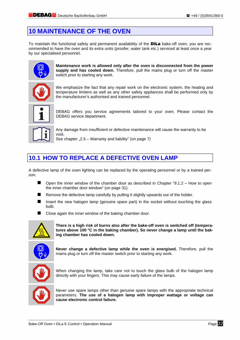
10 MAINTENANCE OF THE OVEN To maintain the functional safety and permanent availability of the DiLa bake-off oven, you are rec-ommended to have the oven and its extra units (proofer, water tank etc.) serviced at least once a year by our specialised personnel.
Maintenance work is allowed only after the oven is disconnected from the power supply and has cooled down. Therefore, pull the mains plug or turn off the master switch prior to starting any work.
We emphasize the fact that any repair work on the electronic system, the heating and temperature limiters as well as any other safety appliances shall be performed only by the manufacturer’s authorised and trained personnel.
DEBAG offers you service agreements tailored to your oven. Please contact the DEBAG service department.
Any damage from insufficient or defective maintenance will cause the warranty to be void. See chapter „2.5 – Warranty and liability” (on page 7)
10.1 HOW TO REPLACE A DEFECTIVE OVEN LAMP A defective lamp of the oven lighting can be replaced by the operating personnel or by a trained per-son.
Open the inner window of the chamber door as described in Chapter "9.1.2 – How to open the inner chamber door window” (on page 31).
Remove the defective lamp carefully by pulling it slightly upwards out of the holder.
Insert the new halogen lamp (genuine spare part) in the socket without touching the glass bulb.
Close again the inner window of the baking chamber door.
There is a high risk of burns also after the bake-off oven is switched off (tempera-tures above 100 °C in the baking chamber). So never change a lamp until the bak-ing chamber has cooled down.
Never change a defective lamp while the oven is energised. Therefore, pull the mains plug or turn off the master switch prior to starting any work.
When changing the lamp, take care not to touch the glass bulb of the halogen lamp directly with your fingers. This may cause early failure of the lamps.
Never use spare lamps other than genuine spare lamps with the appropriate technical parameters. The use of a halogen lamp with improper wattage or voltage can cause electronic control failure.
Bake-Off Oven • DiLa E Control • Operation Manual Page 32
Deutsche Backofenbau GmbH +49 / (0)3591/360-0
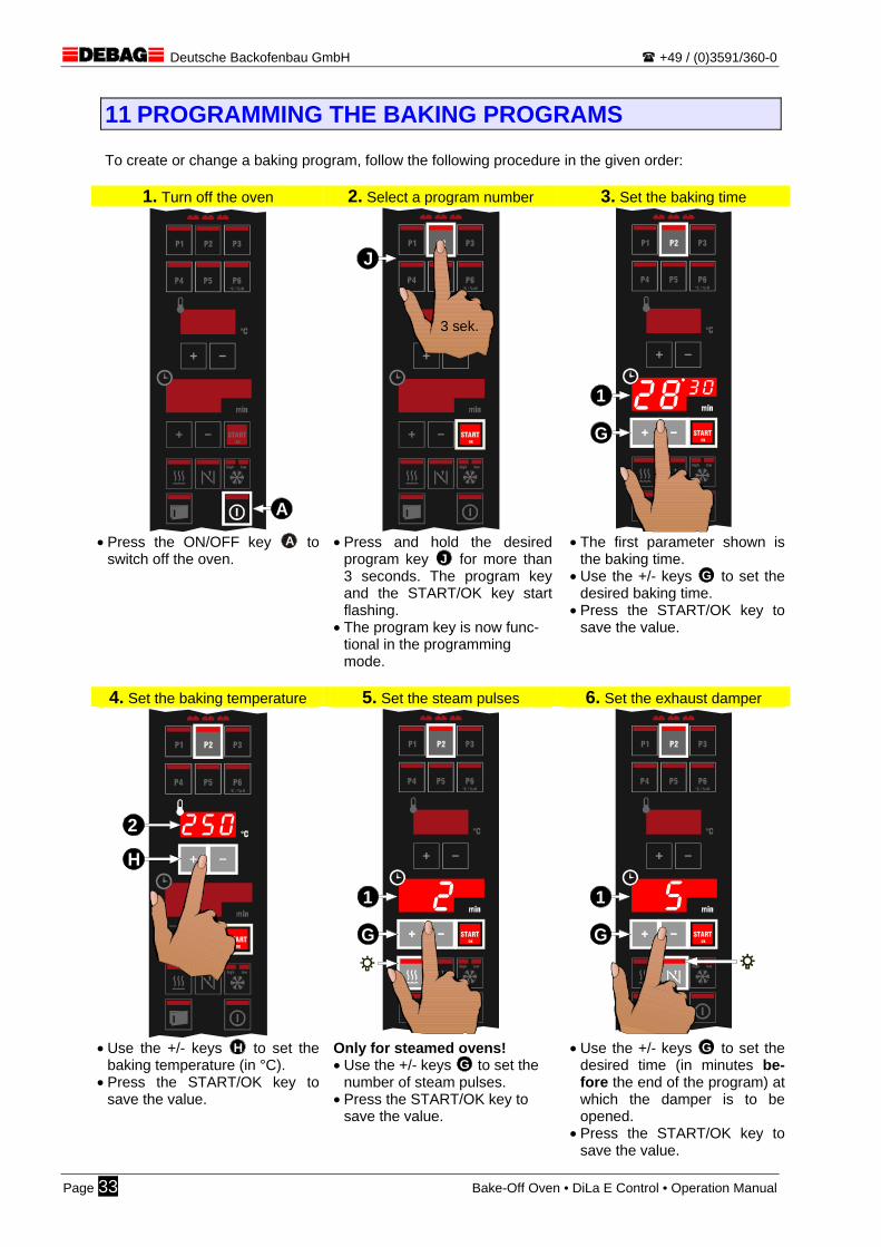
11 PROGRAMMING THE BAKING PROGRAMS To create or change a baking program, follow the following procedure in the given order:
1. Turn off the oven 2. Select a program number 3. Set the baking time
START
P2
P5
P3
P6
P1
P4
lowhigh
°C / %rH
OK
A
START
P2
P5
P3
P6
P1
P4
lowhigh
°C / %rH
OK
3 sek.
J
START
P2
P5
P3
P6
P1
P4
lowhigh
°C / %rH
OK
1
G
• Press the ON/OFF key A to
switch off the oven. • Press and hold the desired
program key J for more than 3 seconds. The program key and the START/OK key start flashing.
• The program key is now func-tional in the programming mode.
• The first parameter shown is the baking time.
• Use the +/- keys G to set the desired baking time.
• Press the START/OK key to save the value.
4. Set the baking temperature 5. Set the steam pulses 6. Set the exhaust damper
START
P2
P5
P3
P6
P1
P4
lowhigh
°C / %rH
OK
H
2
START
P2
P5
P3
P6
P1
P4
lowhigh
°C / %rH
OK
1
G
START
P2
P5
P3
P6
P1
P4
lowhigh
°C / %rH
OK
1
G
• Use the +/- keys H to set the
baking temperature (in °C). • Press the START/OK key to
save the value.
Only for steamed ovens! • Use the +/- keys G to set the
number of steam pulses. • Press the START/OK key to
save the value.
• Use the +/- keys G to set the desired time (in minutes be-fore the end of the program) at which the damper is to be opened.
• Press the START/OK key to save the value.
Page 33 Bake-Off Oven • DiLa E Control • Operation Manual

Deutsche Backofenbau GmbH +49 / (0)3591/360-0
7. Set the fan speed 8. Save End of programming mode
START
P2
P5
P3
P6
P1
P4
lowhigh
°C / %rH
OK
C
START
P2
P5
P3
P6
P1
P4
lowhigh
°C / %rH
OK F
START
P2
P5
P3
P6
P1
P4
lowhigh
°C / %rH
OK
Option only! • Press the fan speed key C to
select the desired speed range. high = fast low = slow
• Use the START/OK key F to save the fan speed range.
• The programming process is over.
For ovens without fan speed ranges, the programming oper-ation already ends after step 6.
• The oven is back in OFF con-dition.
• If desired, you can proceed to the next program number (re-start step 2).
The value range and input order are fixed within the control system. It is not possible to select a single parameter. If the ON/OFF key A is actuated during the programming process, the operation is cancelled without saving. The baking program remains un-changed.
If the baking time is set to “00:00” minutes, the program number is deactivated and can no longer be selected during normal oven operation. In such case, the programming process ends already after step 3.
11.1.1 Automatically determined baking parameters
The following baking parameters are automatically computed by the controller during the programming process and are not visible:
Baking parameters Computation Start temperature (preheat temperature) Baking temperature + 10° Start-to-baking temp. changeover time 1 min after start of baking program
Steam pulse duration High-performance steam: 2.0 sec per pulse Impeller steam: 10.0 sec per pulse
Pulse-to-pulse interval High-performance steam: 10 sec Impeller steam: 12 sec
Hint for experts: The given values are default settings and can be adjusted to your needs in the oven parameters (Appendix 20 – on page 58).
Bake-Off Oven • DiLa E Control • Operation Manual Page 34
Deutsche Backofenbau GmbH +49 / (0)3591/360-0
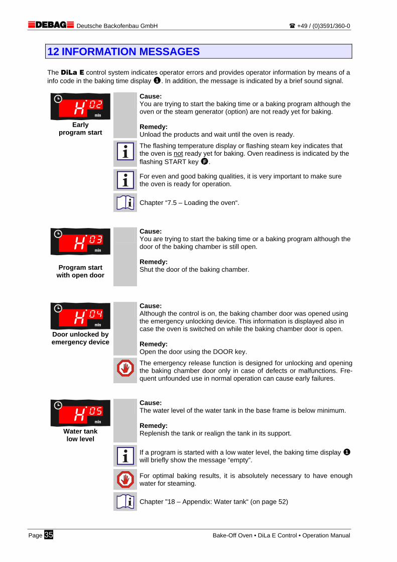
12 INFORMATION MESSAGES The DiLa E control system indicates operator errors and provides operator information by means of a info code in the baking time display 1 . In addition, the message is indicated by a brief sound signal.
Early
program start
Cause: You are trying to start the baking time or a baking program although the oven or the steam generator (option) are not ready yet for baking. Remedy: Unload the products and wait until the oven is ready.
The flashing temperature display or flashing steam key indicates that the oven is not ready yet for baking. Oven readiness is indicated by the flashing START key F .
For even and good baking qualities, it is very important to make sure the oven is ready for operation.
Chapter “7.5 – Loading the oven“.
Program start with open door
Cause: You are trying to start the baking time or a baking program although the door of the baking chamber is still open. Remedy: Shut the door of the baking chamber.
Door unlocked by emergency device
Cause: Although the control is on, the baking chamber door was opened using the emergency unlocking device. This information is displayed also in case the oven is switched on while the baking chamber door is open. Remedy: Open the door using the DOOR key.
The emergency release function is designed for unlocking and opening the baking chamber door only in case of defects or malfunctions. Fre-quent unfounded use in normal operation can cause early failures.
Water tank low level
Cause: The water level of the water tank in the base frame is below minimum. Remedy: Replenish the tank or realign the tank in its support.
If a program is started with a low water level, the baking time display 1 will briefly show the message “empty”.
For optimal baking results, it is absolutely necessary to have enough water for steaming.
Chapter "18 – Appendix: Water tank“ (on page 52)
Page 35 Bake-Off Oven • DiLa E Control • Operation Manual
Deutsche Backofenbau GmbH +49 / (0)3591/360-0
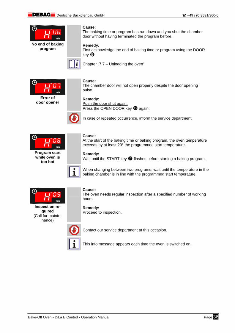
No end of baking
program
Cause: The baking time or program has run down and you shut the chamber door without having terminated the program before. Remedy: First acknowledge the end of baking time or program using the DOOR key B .
Chapter „7.7 – Unloading the oven“
Error of
door opener
Cause: The chamber door will not open properly despite the door opening pulse. Remedy: Push the door shut again. Press the OPEN DOOR key B again.
In case of repeated occurrence, inform the service department.
Program start while oven is
too hot
Cause: At the start of the baking time or baking program, the oven temperature exceeds by at least 20° the programmed start temperature. Remedy: Wait until the START key F flashes before starting a baking program.
When changing between two programs, wait until the temperature in the baking chamber is in line with the programmed start temperature.
Inspection re-
quired (Call for mainte-
nance)
Cause: The oven needs regular inspection after a specified number of working hours. Remedy: Proceed to inspection.
Contact our service department at this occasion.
This info message appears each time the oven is switched on.
Bake-Off Oven • DiLa E Control • Operation Manual Page 36
Deutsche Backofenbau GmbH +49 / (0)3591/360-0
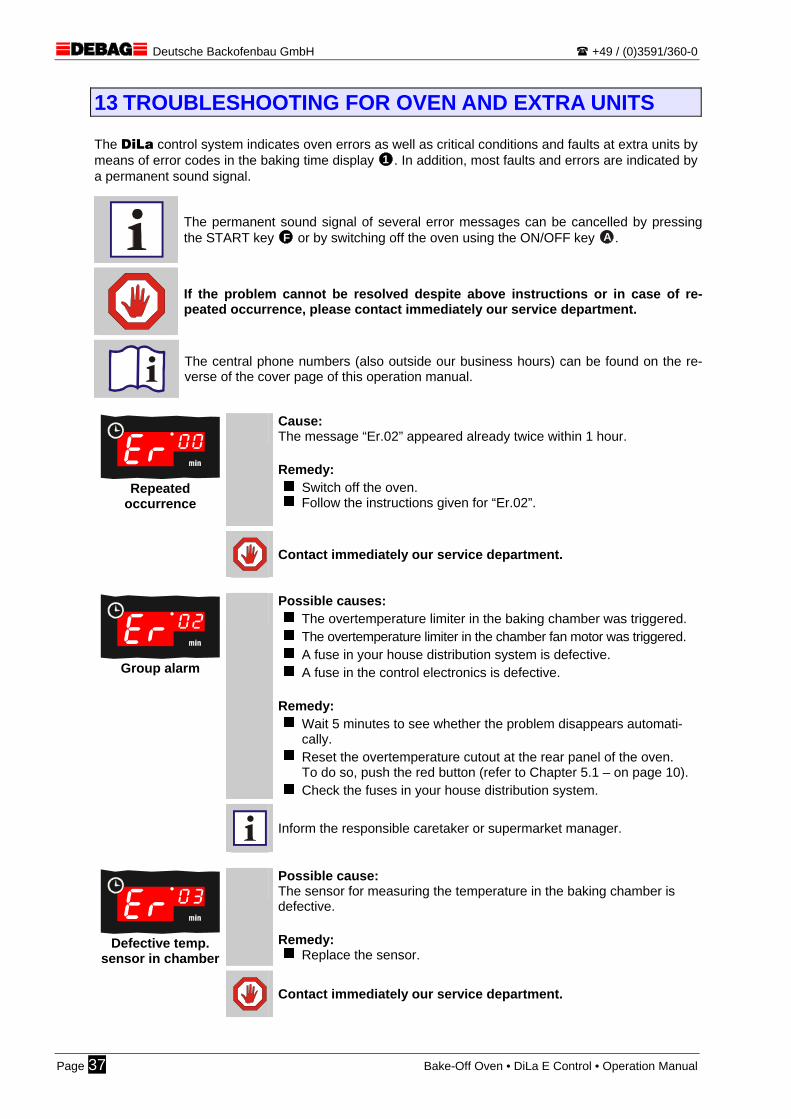
13 TROUBLESHOOTING FOR OVEN AND EXTRA UNITS The DiLa control system indicates oven errors as well as critical conditions and faults at extra units by means of error codes in the baking time display 1 . In addition, most faults and errors are indicated by a permanent sound signal.
The permanent sound signal of several error messages can be cancelled by pressing the START key F or by switching off the oven using the ON/OFF key A .
If the problem cannot be resolved despite above instructions or in case of re-peated occurrence, please contact immediately our service department.
The central phone numbers (also outside our business hours) can be found on the re-verse of the cover page of this operation manual.
Repeated
occurrence
Cause: The message “Er.02” appeared already twice within 1 hour. Remedy:
Switch off the oven. Follow the instructions given for “Er.02”.
Contact immediately our service department.
Group alarm
Possible causes: The overtemperature limiter in the baking chamber was triggered. The overtemperature limiter in the chamber fan motor was triggered. A fuse in your house distribution system is defective. A fuse in the control electronics is defective.
Remedy:
Wait 5 minutes to see whether the problem disappears automati-cally.
Reset the overtemperature cutout at the rear panel of the oven. To do so, push the red button (refer to Chapter 5.1 – on page 10).
Check the fuses in your house distribution system.
Inform the responsible caretaker or supermarket manager.
Defective temp.
sensor in chamber
Possible cause: The sensor for measuring the temperature in the baking chamber is defective. Remedy:
Replace the sensor.
Contact immediately our service department.
Page 37 Bake-Off Oven • DiLa E Control • Operation Manual

Deutsche Backofenbau GmbH +49 / (0)3591/360-0
Defective temp.
sensor in control
Cause: The sensor for measuring the temperature in the control electronics is defective. Remedy:
Replace the control electronics.
Contact immediately our service department. Further oven operation is possible.
Too high temp.
in control
Cause: The control temperature has exceeded its upper limit. Remedy:
Clean the ventilation slots in the rear panel of the oven. Remove any oven covers. Install the oven in a place with sufficient free space around.
Further oven operation is possible. But longer oven operation under these circumstances may cause fail-ures in the control electronics.
Heating power
too low
Cause: The oven heating works permanently and the set temperature is not reached. Remedy:
Switch the oven off and then on again.
In case of repeated occurrence, please contact our service de-partment.
Evaporator won’t heat
Only for ovens with evaporator!
Cause: The heater of the external evaporator hasn’t worked for more than 3 hours. Remedy:
Reset the overtemperature cutout at the rear panel of the oven. To do so, push the red button (refer to Chapter 5.1 – on page 10).
Switch the oven off and then on again.
In case of repeated occurrence, please contact our service de-partment.
Backup battery
is dead
Cause: The backup battery required for the internal clock is almost dead. This message can appear only in ovens with activated automatic start function. Remedy:
Replace the battery.
Contact our service department.
Further oven operation is possible, the automatic start function is deac-tivated. All data other than the current time are independent of the backup bat-tery. So no data losses can occur.
Bake-Off Oven • DiLa E Control • Operation Manual Page 38
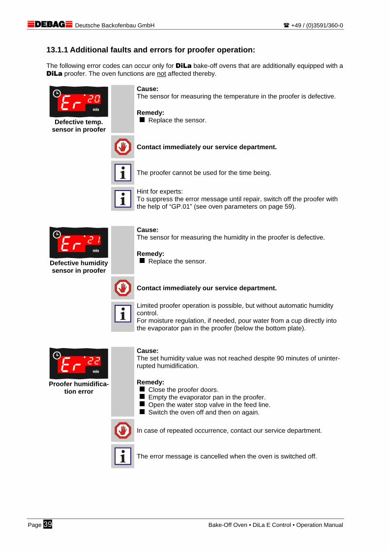
Deutsche Backofenbau GmbH +49 / (0)3591/360-0
13.1.1 Additional faults and errors for proofer operation: The following error codes can occur only for DiLa bake-off ovens that are additionally equipped with a DiLa proofer. The oven functions are not affected thereby.
Defective temp.
sensor in proofer
Cause: The sensor for measuring the temperature in the proofer is defective. Remedy:
Replace the sensor.
Contact immediately our service department.
The proofer cannot be used for the time being.
Hint for experts: To suppress the error message until repair, switch off the proofer with the help of “GP.01” (see oven parameters on page 59).
Defective humidity sensor in proofer
Cause: The sensor for measuring the humidity in the proofer is defective. Remedy:
Replace the sensor.
Contact immediately our service department.
Limited proofer operation is possible, but without automatic humidity control. For moisture regulation, if needed, pour water from a cup directly into the evaporator pan in the proofer (below the bottom plate).
Proofer humidifica-
tion error
Cause: The set humidity value was not reached despite 90 minutes of uninter-rupted humidification. Remedy:
Close the proofer doors. Empty the evaporator pan in the proofer. Open the water stop valve in the feed line. Switch the oven off and then on again.
In case of repeated occurrence, contact our service department.
The error message is cancelled when the oven is switched off.
Page 39 Bake-Off Oven • DiLa E Control • Operation Manual
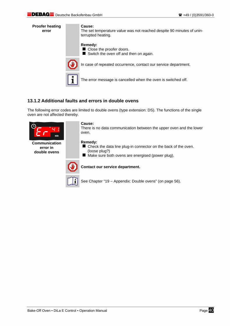
Deutsche Backofenbau GmbH +49 / (0)3591/360-0
Proofer heating error Cause:
The set temperature value was not reached despite 90 minutes of unin-terrupted heating. Remedy:
Close the proofer doors. Switch the oven off and then on again.
In case of repeated occurrence, contact our service department.
The error message is cancelled when the oven is switched off.
13.1.2 Additional faults and errors in double ovens The following error codes are limited to double ovens (type extension: DS). The functions of the single oven are not affected thereby.
Communication
error in double ovens
Cause: There is no data communication between the upper oven and the lower oven. Remedy:
Check the data line plug-in connector on the back of the oven. (loose plug?)
Make sure both ovens are energised (power plug),
Contact our service department.
See Chapter "19 – Appendix: Double ovens” (on page 56).
Bake-Off Oven • DiLa E Control • Operation Manual Page 40
Deutsche Backofenbau GmbH +49 / (0)3591/360-0
Page 41 Bake-Off Oven • DiLa E Control • Operation Manual

Deutsche Backofenbau GmbH +49 / (0)3591/360-0
14 APPENDIX A: DECLARATION OF CONFORMITY
DECLARATION OF CONFORMITY
We, DEBAG Deutsche Backofenbau GmbH declare that our product
DiLa BAKE-OFF OVEN
types:
DiLa 5 / DiLa 10 / DiLa 5+5 / DiLa 10+5 and the proposed optional extras
is in compliance with the following standard:
EN 60204-1
In compliance with the requirements of the Directives
89/336/EEC
98/37/EC
93/68/EEC
this product is marked as follows:
The test results are recorded in the test report Certificate No. NG 05047.
DEBAG Deutsche Backofenbau GmbH
Bautzen, 1 October 2003
for the company: Kellert
Managing Director
i. V. Kiesl
Head of Engineering Dept.
Appendix A: Declaration of Conformity Appendix page 42

Deutsche Backofenbau GmbH +49 / (0)3591/360-0
43 Appendix page Declaration of Conformity
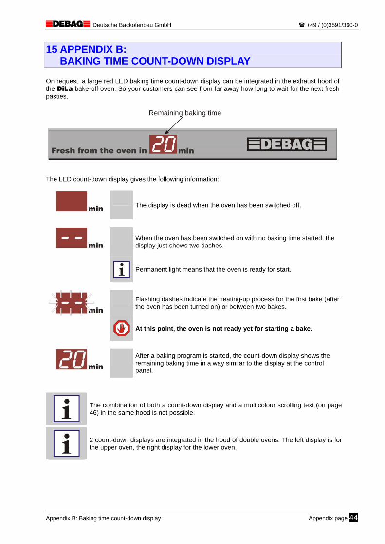
Deutsche Backofenbau GmbH +49 / (0)3591/360-0
15 APPENDIX B: BAKING TIME COUNT-DOWN DISPLAY
On request, a large red LED baking time count-down display can be integrated in the exhaust hood of the DiLa bake-off oven. So your customers can see from far away how long to wait for the next fresh pasties.
Remaining baking time
Fresh from the oven in min
The LED count-down display gives the following information:
The display is dead when the oven has been switched off.
When the oven has been switched on with no baking time started, the display just shows two dashes.
Permanent light means that the oven is ready for start.
Flashing dashes indicate the heating-up process for the first bake (after the oven has been turned on) or between two bakes.
At this point, the oven is not ready yet for starting a bake.
After a baking program is started, the count-down display shows the remaining baking time in a way similar to the display at the control panel.
The combination of both a count-down display and a multicolour scrolling text (on page 46) in the same hood is not possible.
2 count-down displays are integrated in the hood of double ovens. The left display is for the upper oven, the right display for the lower oven.
Appendix B: Baking time count-down display Appendix page 44
Deutsche Backofenbau GmbH +49 / (0)3591/360-0
45 Appendix page

Deutsche Backofenbau GmbH +49 / (0)3591/360-0
16 APPENDIX C: MULTICOLOUR SCROLLING TEXT DISPLAY
On request, a "BETAbrite" multicoloured scrolling text display can be integrated in the exhaust hood of the DiLa bake-off oven. This display gives you the possibility to create and present attractive advertis-ing texts and inform your customers on special offers in a readily visible display.
“BETAbrite” scrolling text Infrared receiver
The following description is meant to give you some brief and in most cases sufficient information on how to enter your own scrolling texts. The quickest and easiest way to enter your text:
PROGRAMRUN
RETURNnächste Zeile
Capital and small letters
SPACELeerzeichen
DELETELöschen
Hold this side in the direction of the oven!
PROGRAM
ON/OFFCAPS LOCK
1
6
A
F
K
P
U
Z
MODE
2
7
B
G
L
Q
V
SPACE
FONT
3
8
C
H
M
R
W
RETURN
SELECTDELETE
FCN
4
9
D
I
N
S
X
RUN
5
0
E
J
O
T
Y
Hold the "BETAbrite" remote control with the IR source pointing to the exhaust hood of the oven and press the "PROGRAM" key. "PROG TEXT A" will appear on the scrolling text screen. Only when "PROG TEXT ?" is shown instead, press "SELECT" and then "A".
Enter your text using the alphabet keys. - To enter a space, press "SPACE". - To cancel a letter, press "DELETE". - To start a new line, press "RETURN". - To change between capital and small letters and back, press "FCN" and "MODE" simultaneously.
Appendix C: Multicolour scrolling text display Appendix page 46
Deutsche Backofenbau GmbH +49 / (0)3591/360-0
To save the entered text, press the "RUN" key twice.
Your scrolling text will then be shown in the display with continuously changing effects and colours.
If you wish specific colour assignments, special effects or graphics, please refer to the enclosed "BETAbrite" Programming Manual.
A comfortable way to program scrolling texts is to connect a PC. To do this, you need the BMS software, which can be ordered (price on request).
To switch off the scrolling text (e.g. over night), press the "FCN" and "PROGRAM" keys simultaneously. Use the same procedure for switching the scrolling text on.
The combination of both a count-down display and a multicolour scrolling text (on page 44) in the exhaust hood is not possible.
47 Appendix page Appendix C: Multicolour scrolling text display
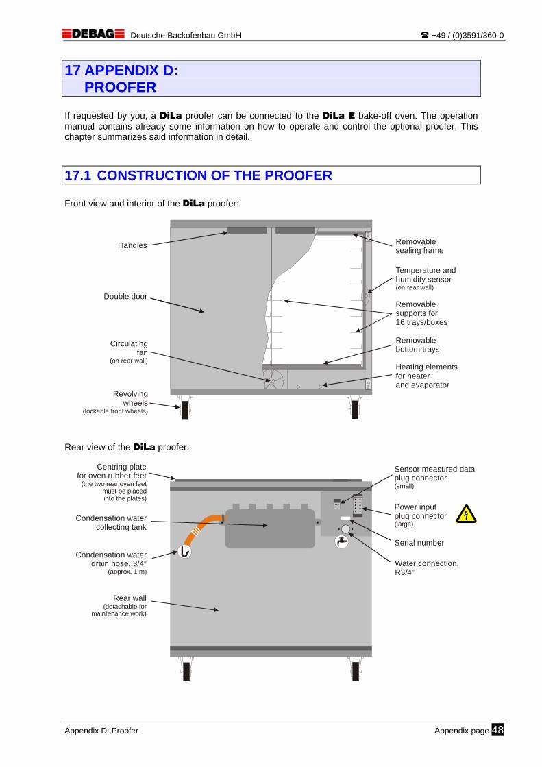
Deutsche Backofenbau GmbH +49 / (0)3591/360-0
17 APPENDIX D: PROOFER
If requested by you, a DiLa proofer can be connected to the DiLa E bake-off oven. The operation manual contains already some information on how to operate and control the optional proofer. This chapter summarizes said information in detail.
17.1 CONSTRUCTION OF THE PROOFER Front view and interior of the DiLa proofer:
Double door
Revolvingwheels
(lockable front wheels)
Circulatingfan
(on rear wall)
Handles Removablesealing frame
Removablesupports for16 trays/boxes
Removablebottom trays
Heating elements for heaterand evaporator
Temperature andhumidity sensor(on rear wall)
Rear view of the DiLa proofer:
Rear wall(detachable for
maintenance work)
Condensation watercollecting tank
Centring platefor oven rubber feet
(the two rear oven feet must be placed into the plates)
Serial number
Water connection,R3/4”
Power inputplug connector(large)
Sensor measured dataplug connector(small)
Condensation waterdrain hose, 3/4”
(approx. 1 m)
Appendix D: Proofer Appendix page 48
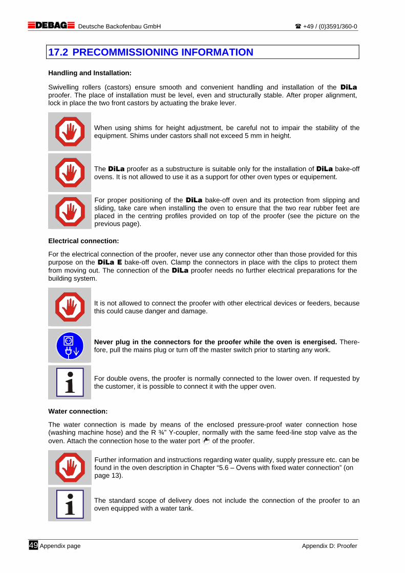
Deutsche Backofenbau GmbH +49 / (0)3591/360-0
17.2 PRECOMMISSIONING INFORMATION Handling and Installation: Swivelling rollers (castors) ensure smooth and convenient handling and installation of the DiLa proofer. The place of installation must be level, even and structurally stable. After proper alignment, lock in place the two front castors by actuating the brake lever.
When using shims for height adjustment, be careful not to impair the stability of the equipment. Shims under castors shall not exceed 5 mm in height.
The DiLa proofer as a substructure is suitable only for the installation of DiLa bake-off ovens. It is not allowed to use it as a support for other oven types or equipement.
For proper positioning of the DiLa bake-off oven and its protection from slipping and sliding, take care when installing the oven to ensure that the two rear rubber feet are placed in the centring profiles provided on top of the proofer (see the picture on the previous page).
Electrical connection: For the electrical connection of the proofer, never use any connector other than those provided for this purpose on the DiLa E bake-off oven. Clamp the connectors in place with the clips to protect them from moving out. The connection of the DiLa proofer needs no further electrical preparations for the building system.
It is not allowed to connect the proofer with other electrical devices or feeders, because this could cause danger and damage.
Never plug in the connectors for the proofer while the oven is energised. There-fore, pull the mains plug or turn off the master switch prior to starting any work.
For double ovens, the proofer is normally connected to the lower oven. If requested by the customer, it is possible to connect it with the upper oven.
Water connection: The water connection is made by means of the enclosed pressure-proof water connection hose (washing machine hose) and the R ¾” Y-coupler, normally with the same feed-line stop valve as the oven. Attach the connection hose to the water port of the proofer.
Further information and instructions regarding water quality, supply pressure etc. can be found in the oven description in Chapter “5.6 – Ovens with fixed water connection” (on page 13).
The standard scope of delivery does not include the connection of the proofer to an oven equipped with a water tank.
49 Appendix page Appendix D: Proofer
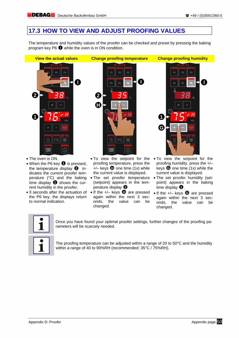
Deutsche Backofenbau GmbH +49 / (0)3591/360-0
17.3 HOW TO VIEW AND ADJUST PROOFING VALUES The temperature and humidity values of the proofer can be checked and preset by pressing the baking program key P6 I while the oven is in ON condition.
View the actual values Change proofing temperature Change proofing humidity
START
P2
P5
P3
P6
P1
P4
lowhigh
°C / %rH
OK
1
2
I
START
P2
P5
P3
P6
P1
P4
lowhigh
°C / %rH
OK
2
H
I
START
P2
P5
P3
P6
P1
P4
lowhigh
°C / %rH
OK
1
G
I
• The oven is ON. • When the P6 key 1 is pressed,
the temperature display 2 in-dicates the current proofer tem-perature (°C) and the baking time display 1 shows the cur-rent humidity in the proofer.
• 3 seconds after the actuation of the P6 key, the displays return to normal indication.
• To view the setpoint for the proofing temperature, press the +/– keys H one time (1x) while the current value is displayed.
• The set proofer temperature (setpoint) appears in the tem-perature display 2
• If the +/– keys H are pressed again within the next 3 sec-onds, the value can be changed.
• To view the setpoint for the proofing humidity, press the +/– keys G one time (1x) while the current value is displayed.
• The set proofer humidity (set-point) appears in the baking time display 1 .
• If the +/– keys G are pressed again within the next 3 sec-onds, the value can be changed.
Once you have found your optimal proofer settings, further changes of the proofing pa-rameters will be scarcely needed.
The proofing temperature can be adjusted within a range of 20 to 50°C and the humidity within a range of 40 to 90%RH (recommended: 35°C / 75%RH).
Appendix D: Proofer Appendix page 50

Deutsche Backofenbau GmbH +49 / (0)3591/360-0
17.4 PROOFER OPERATING INSTRUCTIONS The normal case for DiLa bake-off ovens with proofer is to proof the doughpieces under automatically controlled temperature and humidity conditions in the proofer. The duration of the proofing process and the required atmosphere largely depend on the condition of the doughpieces and are to be defined and permanently checked by the operators.
The DiLa E bake-off oven has no proofing programs and the baking programs have no impact on the proofer. The atmosphere in the proofer cannot be controlled by hand.
To ensure the air conditioning system works properly, take care to open proofer doors just for the minimum time needed for inserting or removing baking trays.
17.4.1 Cleaning: Daily cleaning operations are:
Wipe the whole front of the proofer with a moist cloth without scouring agents.
Clean the proofer tray supports and the bottom panel using a moist cloth.
Wipe the rubber profiles of the door with a moist cloth without scouring agents.
The following cleaning work is necessary in weekly or even shorter intervals:
Remove the bottom panel from the proofer and wipe out the bottom section and the steam-ing pan with a moist cloth.
Even when the equipment has been switched off, there is a risk of burns from contact with certain parts of the proofer (evaporator pan, heating elements) after the bottom panel is removed.
Clean the proofer only when it has cooled down and is disconnected from the power supply. Therefore, pull the mains plug or turn off the master switch prior to start-ing any work.
Also follow the information and instructions given for the proofer in Chapter “9 – Clean-ing the oven” (on page 30).
51 Appendix page Appendix D: Proofer

Deutsche Backofenbau GmbH +49 / (0)3591/360-0
18 APPENDIX E: WATER TANK
If no fixed water connection is available in the place where the DiLa E bake-off oven is installed, it is possible, if requested by you, to supply water via a water reservoir integrated in a special base cabi-net. The operation manual contains already some information on particular items in connection with the additional water tank. This chapter summarizes said information in detail.
For ovens having a water tank, never use any substructure other than a special base cabinet made by DEBAG. In such case, the use of supports from other manufacturers is not recommendable. If alternative solutions are necessary in exceptional cases, the design details must be communicated to DEBAG. They may not be used until they are validated in writing by DEBAG.
Due to the reduced steaming capacity in comparison with a fixed water connection, a DiLa oven with water tank is mainly suited for pre-baked products. We cannot guaran-tee for high-quality bakes with products needing much steam. In case of need, your products must be tested in appropriate trials.
18.1 CONSTRUCTION OF BASE CABINET WITH WATER TANK Front view of the DiLa base cabinet with integrated water tank:
Revolvingwheels
(lockable front wheels)
Space forshelf truck,trays, etc.(as ordered)
Door
Lead-in opening (in rear wall)
Door lock
Tank cap with removablehigh-grade steel strainer
Water tank (9 litre capacity)
Tank support
Quick-acting couplingfor suction line
Condensation waterdrain hose
Wastewatercollecting container(bucket, etc.)
Level sensor(option)
Rear view of the DiLa base cabinet:
Lead-inopening
DiLabake-off oven
Condensation water drain hose for oven(3/4”)
Level monitorplug connector
Hose nozzle forpump water feed line
Condensation water collecting tank
Drain hose (3/4”)
Suction linefrom water tank
(silicone hose)
Centring plates(on bottom cabinet ceiling)
Level sensorcable
Appendix E: Water tank Appendix page 52

Deutsche Backofenbau GmbH +49 / (0)3591/360-0
18.2 PRECOMMISSIONING INFORMATION Handling and Installation: Swivelling rollers (castors) ensure smooth and convenient handling and installation of the DiLa base cabinet. The place of installation must be level, even and structurally stable. After proper alignment, lock in place the two front castors by actuating the brake lever.
When using shims for height adjustment, be careful not to impair the stability of the equipment. Shims under castors shall not exceed 5 mm in height.
For proper positioning of the DiLa bake-off oven and its protection from slipping and sliding, take care when installing oven to ensure that the two rear rubber feet are placed in the centring profiles provided on top of the cabinet.
It is not possible to connect a DiLa proofer to an oven with base cabinet and water tank.
Connection: When commissioning the DiLa bake-off oven, connect the water tank in the base cabinet with the oven via the suction line and connect the level sensor (if any). To do so, slip the thin transparent suction hose (10 mm in diameter) until stop over the small hose nozzle at the rear panel of the oven and fix it with the black plastic hose clip 1 enclosed with the delivery. Compress the engaged clip with pliers or with your fingers until the hose is fixed in place. For the electrical connection of the level sensor, plug the screwed connector 2 into the corresponding jack in the rear panel of the oven and turn until stop to secure it in place.
Water tank connection with the oven
A leaking connection or no connection at all with the suction hose will cause steaming problems and thus poor baking results.
When connecting the suction hose and the level sensor cable, avoid sharp bends or tensile loads and keep a sufficient distance from hot surfaces (exhaust pipe etc.).
53 Appendix page Appendix E: Water tank
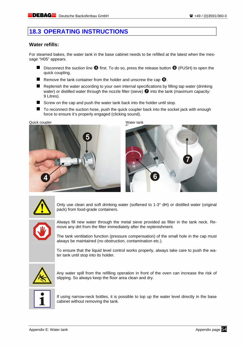
Deutsche Backofenbau GmbH +49 / (0)3591/360-0
18.3 OPERATING INSTRUCTIONS Water refills: For steamed bakes, the water tank in the base cabinet needs to be refilled at the latest when the mes-sage “H05” appears.
Disconnect the suction line 4 first. To do so, press the release button 5 (PUSH) to open the quick coupling.
Remove the tank container from the holder and unscrew the cap 6 .
Replenish the water according to your own internal specifications by filling tap water (drinking water) or distilled water through the nozzle filter (sieve) 7 into the tank (maximum capacity: 9 Litres).
Screw on the cap and push the water tank back into the holder until stop.
To reconnect the suction hose, push the quick coupler back into the socket jack with enough force to ensure it’s properly engaged (clicking sound).
Quick coupler Water tank
Only use clean and soft drinking water (softened to 1-3° dH) or distilled water (original pack) from food-grade containers.
Always fill new water through the metal sieve provided as filter in the tank neck. Re-move any dirt from the filter immediately after the replenishment. The tank ventilation function (pressure compensation) of the small hole in the cap must always be maintained (no obstruction, contamination etc.). To ensure that the liquid level control works properly, always take care to push the wa-ter tank until stop into its holder.
Any water spill from the refilling operation in front of the oven can increase the risk of slipping. So always keep the floor area clean and dry.
If using narrow-neck bottles, it is possible to top up the water level directly in the base cabinet without removing the tank.
Appendix E: Water tank Appendix page 54
Deutsche Backofenbau GmbH +49 / (0)3591/360-0
Cleaning: Daily cleaning operations are:
Wipe the whole front of the base cabinet with a moist cloth without scouring agents.
Clean the water tank with clean drinking water without any additives and check it for leakage every day.
In case of excessive dirt accumulation or water leakage, the water tank must immedi-ately be replaced by a genuine spare tank.
Also follow the information and instructions given in Chapter “9 – Cleaning the oven” (on page 30) for the base cabinet.
Further information:
Remove immediately any leak or entrapped air in the suction hose, because this might cause damage to the steam system.
If the oven is not used for a longer period (holidays, defect etc.), the tank must be com-pletely emptied and dried. The same applies to longer periods with products needing no steam.
The following chapters provide some more information on the base cabinet and water tank:
Chapter “4 – Technical data” (on page 9)
Chapter “5.3 – Substructure requirements“ (on page 11)
Chapter “10 – Maintenance of the oven” (on page 32)
Chapter "12 – Hint messages”(on page 35)"
as well as separate dimension drawings and type sheets.
55 Appendix page Appendix E: Water tank
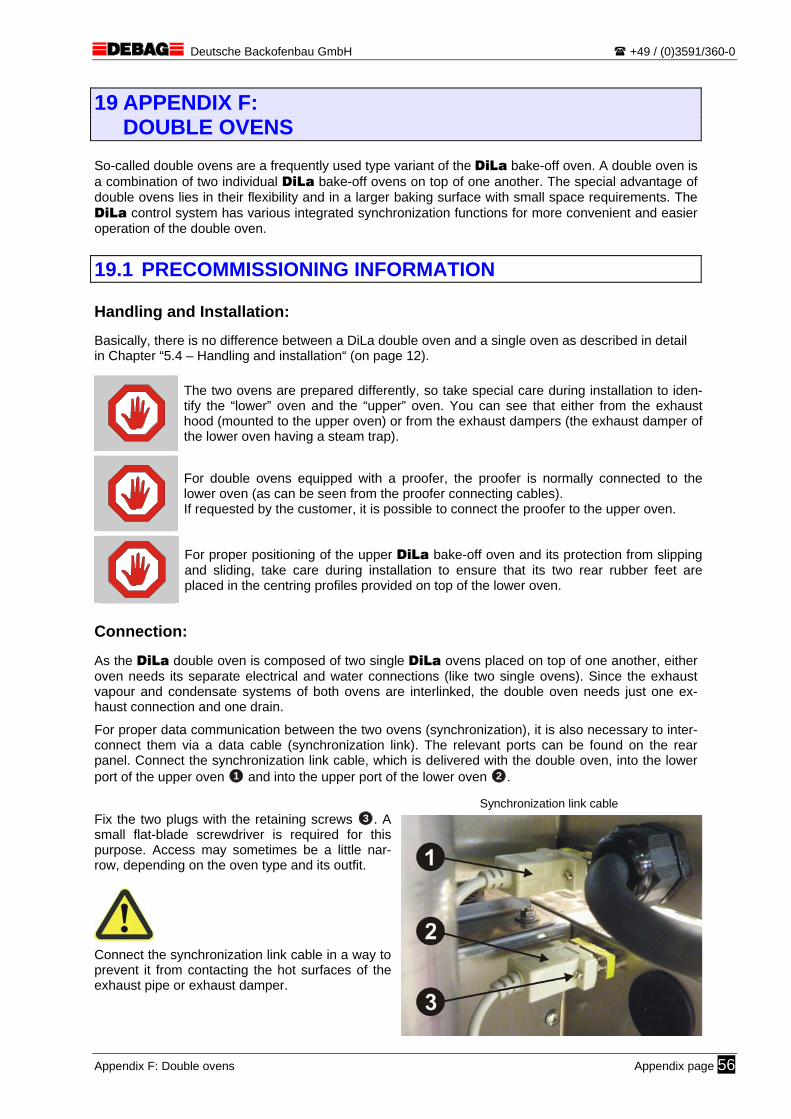
Deutsche Backofenbau GmbH +49 / (0)3591/360-0
19 APPENDIX F: DOUBLE OVENS
So-called double ovens are a frequently used type variant of the DiLa bake-off oven. A double oven is a combination of two individual DiLa bake-off ovens on top of one another. The special advantage of double ovens lies in their flexibility and in a larger baking surface with small space requirements. The DiLa control system has various integrated synchronization functions for more convenient and easier operation of the double oven.
19.1 PRECOMMISSIONING INFORMATION Handling and Installation: Basically, there is no difference between a DiLa double oven and a single oven as described in detail in Chapter “5.4 – Handling and installation“ (on page 12).
The two ovens are prepared differently, so take special care during installation to iden-tify the “lower” oven and the “upper” oven. You can see that either from the exhaust hood (mounted to the upper oven) or from the exhaust dampers (the exhaust damper of the lower oven having a steam trap).
For double ovens equipped with a proofer, the proofer is normally connected to the lower oven (as can be seen from the proofer connecting cables). If requested by the customer, it is possible to connect the proofer to the upper oven.
For proper positioning of the upper DiLa bake-off oven and its protection from slipping and sliding, take care during installation to ensure that its two rear rubber feet are placed in the centring profiles provided on top of the lower oven.
Connection: As the DiLa double oven is composed of two single DiLa ovens placed on top of one another, either oven needs its separate electrical and water connections (like two single ovens). Since the exhaust vapour and condensate systems of both ovens are interlinked, the double oven needs just one ex-haust connection and one drain.
For proper data communication between the two ovens (synchronization), it is also necessary to inter-connect them via a data cable (synchronization link). The relevant ports can be found on the rear panel. Connect the synchronization link cable, which is delivered with the double oven, into the lower port of the upper oven 1 and into the upper port of the lower oven 2 .
Fix the two plugs with the retaining screws 3 . A small flat-blade screwdriver is required for this purpose. Access may sometimes be a little nar-row, depending on the oven type and its outfit.
Connect the synchronization link cable in a way to prevent it from contacting the hot surfaces of the exhaust pipe or exhaust damper.
Synchronization link cable
Appendix F: Double ovens Appendix page 56
Deutsche Backofenbau GmbH +49 / (0)3591/360-0
19.2 OPERATING INSTRUCTIONS The data link between the two ovens gives you additional functions including but not limited to:
The baking time and count-down displays have the same flashing sequences thereby showing very clearly that both ovens belong together.
When setting the current time and date, the changes are automatically adopted by the second oven.
In the basic setting, the optional proofer is turned on automatically as soon as any of the two ovens is switched on (regardless of whether the upper or lower oven). If desired, you can de-activate this function with the oven parameter “OP.38” (on page 58).
Further information:
The data link is functional only when both ovens are connected with the power supply. Whether an oven is switched ON or OFF is of no importance for the data link function.
For cleaning and repair operations, always remember that each oven has its own power feeder and its own water feed line and that it is necessary to pull both power plugs to completely de-energize the double oven.
The following chapters provide some more information on DiLa double ovens:
Chapter “4 – TECHNICAL DATA“ (on page 9)
as well as separate dimension drawings and type sheets.
57 Appendix page Appendix F: Double ovens
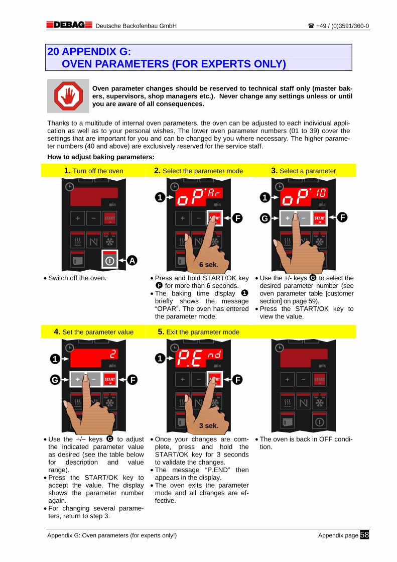
Deutsche Backofenbau GmbH +49 / (0)3591/360-0
20 APPENDIX G: OVEN PARAMETERS (FOR EXPERTS ONLY)
Oven parameter changes should be reserved to technical staff only (master bak-ers, supervisors, shop managers etc.). Never change any settings unless or until you are aware of all consequences.
Thanks to a multitude of internal oven parameters, the oven can be adjusted to each individual appli-cation as well as to your personal wishes. The lower oven parameter numbers (01 to 39) cover the settings that are important for you and can be changed by you where necessary. The higher parame-ter numbers (40 and above) are exclusively reserved for the service staff.
How to adjust baking parameters:
1. Turn off the oven 2. Select the parameter mode 3. Select a parameter
A
6 sek.
F
1
F
1
G
• Switch off the oven.
• Press and hold START/OK key F for more than 6 seconds.
• The baking time display 1 briefly shows the message “OPAR”. The oven has entered the parameter mode.
• Use the +/- keys G to select the desired parameter number (see oven parameter table [customer section] on page 59).
• Press the START/OK key to view the value.
4. Set the parameter value 5. Exit the parameter mode
F
1
GG
3 sek.
F
1
• Use the +/– keys G to adjust
the indicated parameter value as desired (see the table below for description and value range).
• Press the START/OK key to accept the value. The display shows the parameter number again.
• For changing several parame-ters, return to step 3.
• Once your changes are com-plete, press and hold the START/OK key for 3 seconds to validate the changes.
• The message “P.END” then appears in the display.
• The oven exits the parameter mode and all changes are ef-fective.
• The oven is back in OFF condi-tion.
Appendix G: Oven parameters (for experts only!) Appendix page 58
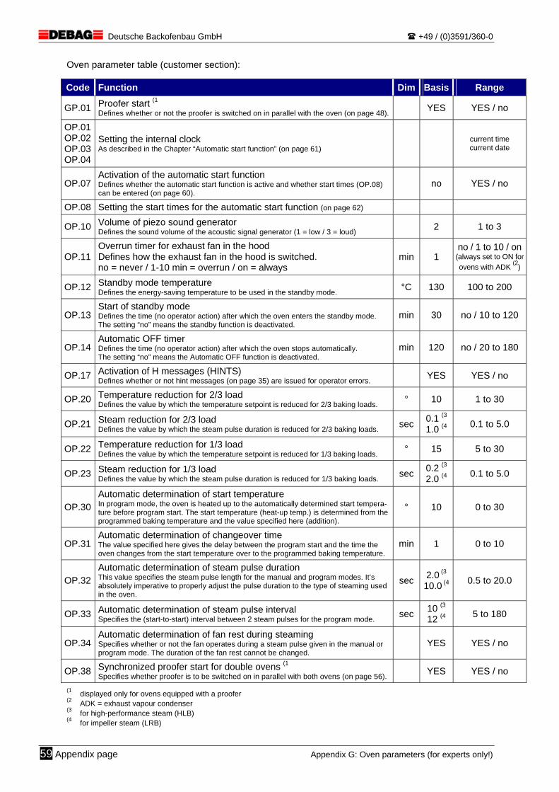
Deutsche Backofenbau GmbH +49 / (0)3591/360-0
Oven parameter table (customer section):
Code Function Dim Basis Range
GP.01 Proofer start (1 Defines whether or not the proofer is switched on in parallel with the oven (on page 48). YES YES / no
OP.01 OP.02 OP.03 OP.04
Setting the internal clock As described in the Chapter “Automatic start function” (on page 61) current time
current date
OP.07 Activation of the automatic start function Defines whether the automatic start function is active and whether start times (OP.08) can be entered (on page 60).
no YES / no
OP.08 Setting the start times for the automatic start function (on page 62)
OP.10 Volume of piezo sound generator Defines the sound volume of the acoustic signal generator (1 = low / 3 = loud) 2 1 to 3
OP.11 Overrun timer for exhaust fan in the hood Defines how the exhaust fan in the hood is switched. no = never / 1-10 min = overrun / on = always
min 1 no / 1 to 10 / on
(always set to ON for ovens with ADK (2)
OP.12 Standby mode temperature Defines the energy-saving temperature to be used in the standby mode. °C 130 100 to 200
OP.13 Start of standby mode Defines the time (no operator action) after which the oven enters the standby mode. The setting “no” means the standby function is deactivated.
min 30 no / 10 to 120
OP.14 Automatic OFF timer Defines the time (no operator action) after which the oven stops automatically. The setting “no” means the Automatic OFF function is deactivated.
min 120 no / 20 to 180
OP.17 Activation of H messages (HINTS) Defines whether or not hint messages (on page 35) are issued for operator errors. YES YES / no
OP.20 Temperature reduction for 2/3 load Defines the value by which the temperature setpoint is reduced for 2/3 baking loads. ° 10 1 to 30
OP.21 Steam reduction for 2/3 load Defines the value by which the steam pulse duration is reduced for 2/3 baking loads. sec 0.1 (3
1.0 (4 0.1 to 5.0
OP.22 Temperature reduction for 1/3 load Defines the value by which the temperature setpoint is reduced for 1/3 baking loads. ° 15 5 to 30
OP.23 Steam reduction for 1/3 load Defines the value by which the steam pulse duration is reduced for 1/3 baking loads. sec 0.2 (3
2.0 (4 0.1 to 5.0
OP.30 Automatic determination of start temperature In program mode, the oven is heated up to the automatically determined start tempera-ture before program start. The start temperature (heat-up temp.) is determined from the programmed baking temperature and the value specified here (addition).
° 10 0 to 30
OP.31 Automatic determination of changeover time The value specified here gives the delay between the program start and the time the oven changes from the start temperature over to the programmed baking temperature.
min 1 0 to 10
OP.32 Automatic determination of steam pulse duration This value specifies the steam pulse length for the manual and program modes. It’s absolutely imperative to properly adjust the pulse duration to the type of steaming used in the oven.
sec 2.0 (3 10.0 (4 0.5 to 20.0
OP.33 Automatic determination of steam pulse interval Specifies the (start-to-start) interval between 2 steam pulses for the program mode. sec 10 (3
12 (4 5 to 180
OP.34 Automatic determination of fan rest during steaming Specifies whether or not the fan operates during a steam pulse given in the manual or program mode. The duration of the fan rest cannot be changed.
YES YES / no
OP.38 Synchronized proofer start for double ovens (1Specifies whether proofer is to be switched on in parallel with both ovens (on page 56). YES YES / no
(1 displayed only for ovens equipped with a proofer (2 ADK = exhaust vapour condenser (3 for high-performance steam (HLB) (4 for impeller steam (LRB)
59 Appendix page Appendix G: Oven parameters (for experts only!)

Deutsche Backofenbau GmbH +49 / (0)3591/360-0
21 APPENDIX H: AUTOMATIC START FUNCTION
The integrated automatic start function makes it possible to start the oven and any connected extra units (e.g. proofer) automatically once a day. At the programmed time, the oven will automatically start (like pressing the ON/OFF button A ) and heat up to the set baking temperature (manual mode) or to the start temperature of the last selected baking program (program mode). A different start time can be selected for every day of the week. The oven is delivered with the automatic start function being deactivated. To be able to use this spe-cial function, you must make the necessary settings with the help of the oven parameters first.
Oven parameter changes should be reserved to technical staff only (master bak-ers, supervisors, shop managers, briefed operators etc.).
When stopping the oven at the end of a day, unload it completely. For fire safety reasons, never leave products unattended in the oven for any purpose whatso-ever, such as drying etc.
The oven will not start automatically in case of trouble situations or if the door of the baking chamber was left open. For safety reasons, the oven will stop automatically if no action is made within 60 minutes after an automatic start.
Refer to chapter “20 – Appendix: Oven parameters” (on page 58) for a detailed description of how to program the oven parameters.
21.1 ACTIVITATION OF THE AUTOMATIC START FUNCTION The automatic start function is activated with the help of oven parameter “OP.07”.
Code Function Dim Basis Range
OP.07 Activation of the automatic start function Defines whether the automatic start function is active and whether start times (OP.08) can be entered.
no YES / no
setting”no”: The automatic start function is not active (default setting).
The oven parameters for setting the current time and the start times are not avail-able.
setting “YES”: The oven will start automatically at the programmed times. When the oven is in its OFF condition, the baking time display shows the current time with the START key being illuminated (LED). If the START key is pressed, the baking time display will show the next programmed start time and the temperature display will indicate the related weekday (also refer to the skip function on page 63). The oven parameters for setting the current time and the start times are available.
If the oven is not used for a longer period, it is wise to deactivate the automatic start function.
Appendix H: Automatic start function Appendix page 60
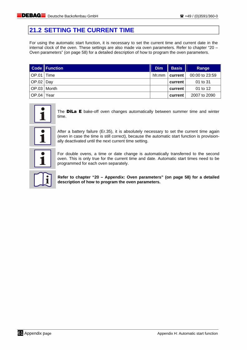
Deutsche Backofenbau GmbH +49 / (0)3591/360-0
21.2 SETTING THE CURRENT TIME For using the automatic start function, it is necessary to set the current time and current date in the internal clock of the oven. These settings are also made via oven parameters. Refer to chapter “20 – Oven parameters” (on page 58) for a detailed description of how to program the oven parameters. Code Function Dim Basis Range
OP.01 Time hh:mm current 00:00 to 23:59 OP.02 Day current 01 to 31 OP.03 Month current 01 to 12 OP.04 Year current 2007 to 2090
The DiLa E bake-off oven changes automatically between summer time and winter time.
After a battery failure (Er.35), it is absolutely necessary to set the current time again (even in case the time is still correct), because the automatic start function is provision-ally deactivated until the next current time setting.
For double ovens, a time or date change is automatically transferred to the second oven. This is only true for the current time and date. Automatic start times need to be programmed for each oven separately.
Refer to chapter “20 – Appendix: Oven parameters” (on page 58) for a detailed description of how to program the oven parameters.
61 Appendix page Appendix H: Automatic start function
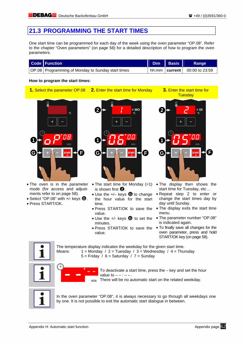
Deutsche Backofenbau GmbH +49 / (0)3591/360-0
21.3 PROGRAMMING THE START TIMES One start time can be programmed for each day of the week using the oven parameter “OP.08”. Refer to the chapter “Oven parameters” (on page 58) for a detailed description of how to program the oven parameters. Code Function Dim Basis Range
OP.08 Programming of Monday to Sunday start times hh:mm current 00:00 to 23:59 How to program the start times:
1. Select the parameter OP.08 2. Enter the start time for Monday 3. Enter the start time for Tuesday
STARTOK
F
1
G
STARTOK
= MO
F
1
2
G
STARTOK
= DI
F
1
2
G
• The oven is in the parameter
mode (for access and adjust-ments refer to on page 58).
• Select “OP.08” with +/- keys G . • Press START/OK.
• The start time for Monday (=1) is shown first 2 .
• Use the +/– keys G to change the hour value for the start time.
• Press START/OK to save the value.
• Use the +/- keys G to set the minutes.
• Press START/OK to save the value.
• The display then shows the start time for Tuesday, etc…
• Repeat step 2 to enter or change the start times day by day until Sunday.
• The display exits the start time menu.
• The parameter number “OP.08” is indicated again.
• To finally save all changes for the oven parameter, press and hold START/OK key (on page 58).
The temperature display indicates the weekday for the given start time. Means: 1 = Monday / 2 = Tuesday / 3 = Wednesday / 4 = Thursday 5 = Friday / 6 = Saturday / 7 = Sunday
To deactivate a start time, press the – key and set the hour value to – – : – – . There will be no automatic start on the related weekday.
In the oven parameter “OP.08”, it is always necessary to go through all weekdays one by one. It is not possible to exit the automatic start dialogue in between.
Appendix H: Automatic start function Appendix page 62
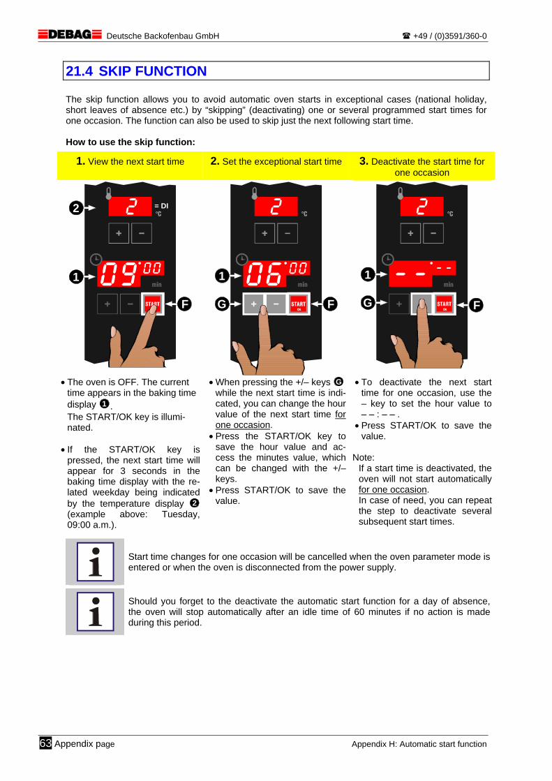
Deutsche Backofenbau GmbH +49 / (0)3591/360-0
21.4 SKIP FUNCTION The skip function allows you to avoid automatic oven starts in exceptional cases (national holiday, short leaves of absence etc.) by “skipping” (deactivating) one or several programmed start times for one occasion. The function can also be used to skip just the next following start time. How to use the skip function:
1. View the next start time 2. Set the exceptional start time 3. Deactivate the start time for one occasion
STARTOK
= DI
F
1
2
STARTOK
F
1
G
STARTOK F
1
G
• The oven is OFF. The current time appears in the baking time display 1 . The START/OK key is illumi-nated.
• If the START/OK key is
pressed, the next start time will appear for 3 seconds in the baking time display with the re-lated weekday being indicated by the temperature display 2 (example above: Tuesday, 09:00 a.m.).
• When pressing the +/– keys G while the next start time is indi-cated, you can change the hour value of the next start time for one occasion.
• Press the START/OK key to save the hour value and ac-cess the minutes value, which can be changed with the +/– keys.
• Press START/OK to save the value.
• To deactivate the next start time for one occasion, use the – key to set the hour value to– – : – – .
• Press START/OK to save the value.
Note:
If a start time is deactivated, the oven will not start automatically for one occasion. In case of need, you can repeat the step to deactivate several subsequent start times.
Start time changes for one occasion will be cancelled when the oven parameter mode is entered or when the oven is disconnected from the power supply.
Should you forget to the deactivate the automatic start function for a day of absence, the oven will stop automatically after an idle time of 60 minutes if no action is made during this period.
63 Appendix page Appendix H: Automatic start function
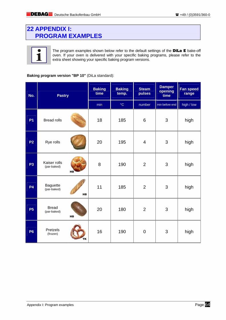
Deutsche Backofenbau GmbH +49 / (0)3591/360-0
22 APPENDIX I: PROGRAM EXAMPLES
The program examples shown below refer to the default settings of the DiLa E bake-off oven. If your oven is delivered with your specific baking programs, please refer to the extra sheet showing your specific baking program versions.
Baking program version "BP 10" (DiLa standard):
Baking time
Baking temp.
Steam pulses
Damper opening
time
Fan speed range No. Pastry
min °C number min before end high / low
P1 Bread rolls
18 185 6 3 high
P2 Rye rolls
20 195 4 3 high
P3 Kaiser rolls (par-baked)
HB
8 190 2 3 high
P4 Baguette (par-baked)
HB
11 185 2 3 high
P5 Bread (par-baked)
HB
20 180 2 3 high
P6 Pretzels (frozen)
TK
16 190 0 3 high
Appendix I: Program examples Page 64

a

Deutsche Backofenbau GmbH +49 / (0)3591/360-0
23 APPENDIX J: BAKING PROGRAM FORM
Master copy! – Please do not fill in the form contained in this manual, but make and use a copy.
Version: ____________________ Drafted by: ______________ Date: ______________
Baking time
Baking temp.
Steam pulses
Damper opening
time
Fan speed range
No. Pastry
min °C number min before end high / low
P1
P2
P3
P4
P5
P6
Appendix J: Baking program form Appendix page 65