Operating Systems YEAR/SEM:III/V YEAR/OPERATING SYSTEMS/Unit 4.p… · Protection: Access -control...
51
Operating Systems YEAR/SEM:III/V Prepared by Mrs.M.Manjula/AP/IT/RGCET Page 1 UNIT-IV File Concept: Access Methods – Directory Structure – File System Mounting – File Sharing – Protection – File System Structure – File System Implementation – Directory Implementation – Allocation Methods – Free-space Management - Kernel I/O Subsystems - Disk Structure – Disk Scheduling – Disk Management – Swap-Space Management. FILE CONCEPT Computers can store information on several different storage media, such as magnetic disks, magnetic tapes, and optical disks. So that the computer system will be convenient to use, the operating system provides a uniform logical view of information storage.The operating system abstracts from the physical properties of its storage devices to define a logical storage unit (the file).Files are mapped, by the operating system, onto physical devices. These storage devices are usually nonvolatile, so the contents are persistent through power failures and system reboots. A file is a named collection of related information that is recorded on secondary storage. From a user's perspective, a file is the smallest allotment of logical secondary storage; that is, data cannot be written to secondary storage unless they are within a file. Commonly, files represent programs (both source and object forms) and data. Data files may be numeric, alphabetic, alphanumeric, or binary. Files may be free form, such as text files, or may be formatted rigidly. In general, a file is a sequence of bits, bytes, lines, or records, the meaning of which is defined by the file's creator and user. The concept of a file is thus extremely general. The information in a file is defined by its creator. Many different types of information may be stored in a file-source programs, object programs, executable programs, numeric data, text, payroll records, graphic images, sound recordings, and so on. A file has a certain defined structure according to its type. A text file is a sequence of characters organized into lines (and possibly pages).A source file is a sequence of subroutines and functions, each of which is further organized as declarations followed by executable statements.An object file is a sequence of bytes organized into blocks understandable by the system's linker.An executable file is a series of code sections that the loader can bring into memory and execute. FILE ATTRIBUTES A file is named, for the convenience of its human users, and is referred to by its name.A name is usually a string of characters, such as examp1e.c. Some systems differentiate between upper- and lowercase characters in names, whereas other systems consider the two cases to be equivalent. When a file is named, it becomes independent of the process, the user, and even the system that created it.For instance, one user might create the file example .c, whereas another user might edit that file by specifying its name. The file's owner might write the file to a floppy disk, send it in an e-mail, or copy it across a network, and it could still be called examp1e.c on the destination system.
Transcript of Operating Systems YEAR/SEM:III/V YEAR/OPERATING SYSTEMS/Unit 4.p… · Protection: Access -control...

Operating Systems YEAR/SEM:III/V
Prepared by Mrs.M.Manjula/AP/IT/RGCET Page 1
UNIT-IV
File Concept: Access Methods – Directory Structure – File System Mounting – File Sharing –
Protection – File System Structure – File System Implementation – Directory Implementation –
Allocation Methods – Free-space Management - Kernel I/O Subsystems - Disk Structure – Disk
Scheduling – Disk Management – Swap-Space Management.
FILE CONCEPT
Computers can store information on several different storage media, such as magnetic disks,
magnetic tapes, and optical disks. So that the computer system will be convenient to use, the operating
system provides a uniform logical view of information storage.The operating system abstracts from the
physical properties of its storage devices to define a logical storage unit (the file).Files are mapped, by the
operating system, onto physical devices. These storage devices are usually nonvolatile, so the contents are
persistent through power failures and system reboots.
A file is a named collection of related information that is recorded on secondary storage. From a
user's perspective, a file is the smallest allotment of logical secondary storage; that is, data cannot be
written to secondary storage unless they are within a file. Commonly, files represent programs (both
source and object forms) and data. Data files may be numeric, alphabetic, alphanumeric, or binary.
Files may be free form, such as text files, or may be formatted rigidly. In general, a file is a
sequence of bits, bytes, lines, or records, the meaning of which is defined by the file's creator and user.
The concept of a file is thus extremely general. The information in a file is defined by its creator. Many
different types of information may be stored in a file-source programs, object programs, executable
programs, numeric data, text, payroll records, graphic images, sound recordings, and so on.
A file has a certain defined structure according to its type. A text file is a sequence of characters
organized into lines (and possibly pages).A source file is a sequence of subroutines and functions, each of
which is further organized as declarations followed by executable statements.An object file is a sequence
of bytes organized into blocks understandable by the system's linker.An executable file is a series of code
sections that the loader can bring into memory and execute.
FILE ATTRIBUTES
A file is named, for the convenience of its human users, and is referred to by its name.A name is
usually a string of characters, such as examp1e.c. Some systems differentiate between upper- and
lowercase characters in names, whereas other systems consider the two cases to be equivalent.
When a file is named, it becomes independent of the process, the user, and even the system that
created it.For instance, one user might create the file example .c, whereas another user might edit that file
by specifying its name.
The file's owner might write the file to a floppy disk, send it in an e-mail, or copy it across a
network, and it could still be called examp1e.c on the destination system.

Operating Systems YEAR/SEM:III/V
Prepared by Mrs.M.Manjula/AP/IT/RGCET Page 2
A file has certain other attributes, which vary from one operating system to another, but typically consist
of these:
Name: The symbolic file name is the only information kept in human readable form.
Identifier: This unique tag, usually a number, identifies the file within the file system; it is the non-
human-readable name for the file.
Type: This information is needed for those systems that support different types.
Location: This information is a pointer to a device and to the location of the file on that device.
Size: The current size of the file (in bytes, words, or blocks), and possibly the maximum allowed size are
included in this attribute.
Protection: Access-control information determines who can do reading, writing, executing, and so on.
Time, date, and user identification: This information may be kept for creation, last modification, and
last use. These data can be useful for protection, security, and usage monitoring.
The information about all files is kept in the directory structure that also resides on secondary
storage. Typically, the directory entry consists of the file's name and its unique identifier. The identifier in
turn locates the other file attributes. It may take more than a kilobyte to record this information for each
file. In a system with many files, the size of the directory itself may be megabytes. Because directories,
like files, must be nonvolatile, they must be stored on the device and brought into memory piecemeal, as
needed.
FILE OPERATION
A file is an abstract data type.To define a file properly, we need to consider the operations that
can be performed on files. The operating system can provide system calls to create, write, read,
reposition, delete, and truncate files.Let us also consider what the operating system must do for each of
the six basic file operations. It should then be easy to see how similar operations, such as renaming a file,
would be implemented.
Creating a file: Two steps are necessary to create a file. First, space in the file system must be found for
the file. Second, an entry for the new file must be made in the directory. The directory entry records the
name of the file and the location in the file system, and possibly other information.
Writing a file: To write a file, we make a system call specifying both the name of the file and the
information to be written to the file. Given the name of the file, the system searches the directory to find
the location of the file. The system must keep a write pointer to the location in the file where the next
write is to take place. The write pointer must be updated whenever a write occurs.
Reading a file: To read from a file, we use a system call that specifies the name of the file and where (in
memory) the next block of the file should be put. Again, the directory is searched for the associated
directory entry, and the system needs to keep a read pointer to the location in the file where the next read
is to take place. Once the read has taken place, the read pointer is updated. A given process is usually only
reading or writing a given file and the current operation location is kept as a per-process current-file-

Operating Systems YEAR/SEM:III/V
Prepared by Mrs.M.Manjula/AP/IT/RGCET Page 3
position pointer. Both the read and write operations use this same pointer, saving space and reducing the
system complexity.
Repositioning within a file: The directory is searched for the appropriate entry, and the current-file-
position is set to a given value. Repositioning within a file does not need to involve any actual I/O. This
file operation is also known as a file seek.
Deleting a file: To delete a file, we search the directory for the named file. Having found the associate
directory entry, we release all file space, so that it can be reused by other files, and erase the directory
entry.
Truncating a file: The user may want to erase the contents of a file but keep its attributes. Rather than
forcing the user to delete the file and then recreate it, this function allows all attributes to remain
unchanged-except for file length-but lets the file be reset to length zero and its file space released.
These six basic operations certainly comprise the minimal set of required file operations.
File pointer: On systems that do not include a file offset as part of the read and write system calls, the
system must track the last read-write location as a current-file-position pointer. This pointer is unique to
each process operating on the file, and therefore must be kept separate from the on-disk file attributes.
File open count: As files are closed, the operating system must reuse its open-file table entries, or it
could run out of space in the table. Because multiple processes may open a file, the system must wait for
the last file to close before removing the open-file table entry. This counter tracks the number of opens
and closes and reaches zero on the last close. The system can then remove the entry.
Disk location of the file: Most file operations require the system to modify data within the file. The
information needed to locate the file on disk is kept in memory to avoid having to read it from disk for
each operation.
Access rights: Each process opens a file in an access mode. This information is stored on the per-process
table so the operating system can allow or deny subsequent I/O requests.
Some operating systems provide facilities to lock sections of an open file for multi-process access, to
share sections of a file among several processes (using shared pages), and to map sections of a file into
memory on virtual- memory systems using memory mapping
FILE TYPES
The following is the types of the files.
A common technique for implementing file types is to include the type as part of the file name.
The name is split into two parts-a name and an extension, usually separated by a period character (Figure
(a)).

Operating Systems YEAR/SEM:III/V
Prepared by Mrs.M.Manjula/AP/IT/RGCET Page 4
Fig (a): Common file types
FILE TYPE USUAL EXTENSION FUNCTION
Executable Exe,com,bin,or none Read to run machine
language program
Object Obj,o Compiled,machine
language,not linked
Source code C,cc,java,pas,asm,a Source code in various
language
Batch Bat,sh Commands to the command
interpreter
Text Txt,doc Texual data,documents
Word processor Wp,tex,rrf,doc Various word processor
format
Library Lib,a,so,dill,mpeg,mov,rm Libraries of the routines for
programmers
Print or view Arc,zip,tar ASCII or binary file in a
format for printing or
viewing
Archive Arc,zip,tar Related files grouped into
A one file sometimes
compressed for archiveing
or storage
Multimedia Mpeg,mov,rm Binary file containing audio
or A/V information

Operating Systems YEAR/SEM:III/V
Prepared by Mrs.M.Manjula/AP/IT/RGCET Page 5
In this way, the user and the operating system can tell from the name alone what the type of a file is. For
example, in MS-DOS, a name can consist of up to eight characters followed by a period and terminated
by an extension of up to three characters. The system uses the extension to indicate the type of the file
and the type of operations that can be done on that file. For instance, only a file with a .corn, .exe, or .bat
extension can be executed. The .corn and .exe files are two forms of binary executable files, whereas a
.bat file is a batch file containing, in ASCII format, commands to the operating system.
FILE STRUCTURE
File types also may be used to indicate the internal structure of the file. Further, certain files must
conform to a required structure that is understood by the operating system.For example, the operating
system may require that an executable file have a specific structure so that it can determine where in
memory to load the file and what the location of the first instruction is.Some operating systems extend
this idea into a set of system-supported file structures, with sets of special operations for manipulating
files with those structures.
For instance, DEC's VMS operating system has a file system that supports three defined file
structures.The above discussion brings us to one of the disadvantages of having the operating system
support multiple file structures:The resulting size of the operating system is cumbersome.If the operating
system defines five different file structures, it needs to contain the code to support these file structures.
In addition, every file may need to be definable as one of the file types supported by the operating
system.Severe problems may result from new applications that require information structured in ways not
supported by the operating system.The Macintosh operating system also supports a minimal number of
file structures.It expects files to contain two parts:
Resource fork: The resource fork contains information of interest to the user. For instance, it holds the
labels of any buttons displayed by the program. A foreign user may want to re-label these buttons in his
own language, and a Macintosh operating system provides tools to allow modification of the data in the
resource fork.
Data fork: the traditional file contents. To accomplish the same task on a UNIX or MS-DOS system, the
programmer would need to change and recompile the source code, unless she created her own user-
changeable data file.
INTERNAL FILE STRUCTURE
Internally, locating an offset within a file can be complicated for the operating system. All disk
I/O is performed in units of one block (physical record), and all blocks are the same size. It is unlikely
that the physical record size will exactly match the length of the desired logical record.
Logical records may even vary in length. Packing a number of logical records into physical
blocks is a common solution to this problem.The logical record size, physical block size, and packing
technique determine how many logical records are in each physical block. The packing can be done either
by the user's application program or by the operating system. In either case, the file may be considered to
be a sequence of blocks.

Operating Systems YEAR/SEM:III/V
Prepared by Mrs.M.Manjula/AP/IT/RGCET Page 6
All the basic I/O functions operate in terms of blocks. The conversion from logical records to
physical blocks is a relatively simple software problem. Because disk space is always allocated in blocks,
some portion of the last block of each file is generally wasted. If each block were 512 bytes, then a file of
1,949 bytes would be allocated four blocks (2,048 bytes); the last 99 bytes would be wasted.
The wasted bytes allocated to keep everything in units of blocks (instead of bytes) are internal
fragmentation. All file systems suffer from internal fragmentation; the larger the block size, the greater
the internal fragmentation.
ACCESS METHOD
Files store information. When it is used, this information must be accessed and read into
computer memory. The information in the file can be accessed in several ways. Some systems provide
only one access method for files. Other systems, such as those of IBM, support many access methods, and
choosing the right one for a particular application is a major design problem.
1. SEQUENTIAL ACCESS
2. DIRECT ACCESS
3. OTHER ACCESS
Sequential Access:
The simplest access method is sequential access. Information in the file is processed in order, one
record after the other. This mode of access is by far the most common; for example, editors and compilers
usually access files in this fashion.
The bulk of the operations on a file is reads and writes. A read operation reads the next portion of
the file and automatically advances a file pointer, which tracks the I/O location.
Similarly, a write appends to the end of the file and advances to the end of the newly written
material (the new end of file). Such a file can be reset to the beginning and, on some systems, a program
may be able to skip forward or backward n records, for some integer n-perhaps only for n = 1.
Sequential access is based on a tape model of a file, and works as well on sequential-access
devices as it does on random-access ones.(fig (A)
Fig (a) Sequential-access file.
Direct Access:
Another method is direct access (or relative access). A file is made up of fixed length logical
records that allow programs to read and write records rapidly in no particular order.
The direct-access method is based on a disk model of a file, since disks allow random access to any file
block. For direct access, the file is viewed as a numbered sequence of blocks or records.

Operating Systems YEAR/SEM:III/V
Prepared by Mrs.M.Manjula/AP/IT/RGCET Page 7
A direct-access file allows arbitrary blocks to be read or written. Thus, we may read block 14, then read
block 53, and then write block 7.
There are no restrictions on the order of reading or writing for a direct-access file. Direct-access
files are of great use for immediate access to large amounts of information. Databases are often of this
type.Thus, the number of available seats for flight 713 is stored in block 713 of the reservation file. To
store information about a larger set, such as people, we might compute a hash function on the people's
names, or search a small in-memory index to determine a block to read and search.
For the direct-access method, the file operations must be modified to include the block number as
a parameter. Thus, we have read n, where n is the block number, rather than read next, and write n rather
than write next. An alternative approach is to retain read next and write next, as with sequential access,
and to add an operation position file to n, where n is the block number.
Then, to effect a read n, we would position to n and then read next.
The block number provided by the user to the operating system is normally a relative block
number.A relative block number: relative block number is an index relative to the beginning of the file.
Thus, the first relative block of the file is 0, the next is 1, and so on, even though the actual absolute disk
address of the block may be 14703 for the first block and 3192 for the second. The use of relative block
numbers allows the operating system to decide where the file should be placed (called the allocation
problem,), and helps to prevent the user from accessing portions of the file system that may not be part of
his file. Some systems start their relative block numbers at 0; others start at 1.
Given a logical record length L, a request for record N is turned into an I/O request for L bytes starting at
location L * (N -1) within the file (assuming first record is N = 1). Since logical records are of a fixed
size, it is also easy to read, write, or delete a record.
Fig:Simulation of sequential access on a direct aces file.
OTHER ACCESS METHODS
Other access methods can be built on top of a direct-access method. These methods generally
involve the construction of an index for the file.

Operating Systems YEAR/SEM:III/V
Prepared by Mrs.M.Manjula/AP/IT/RGCET Page 8
The index, like an index in the back of a book, contains pointers to the various blocks. To find a
record in the file, we first search the index, and then use the pointer to access the file directly and to find
the desired record.
For example, a retail-price file might list the universal product codes (UPCs) for items, with the
associated prices. Each record consists of a 10-digit UPC and a 6-digit price, for a 16-byte record. If our
disk has 1,024 bytes per block, we can store 64 records per block. A file of 120,000 records would occupy
about 2,000 blocks (2 million bytes). By keeping the file sorted by UPC, we can define an index
consisting of the first UPC in each block.
This index would have 2,000 entries of 10 digits each, or 20,000 bytes, and thus could be kept in
memory. To find the price of a particular item, we can (binary) search the index.
From this search, we would know exactly which block contains the desired record and access that block.
This structure allows us to search a large file doing little I/O.
With large files, the index file itself may become too large to be kept in memory. One solution is
to create an index for the index file. The primary index file would contain pointers to secondary index
files, which would point to the actual data items.
For example, IBM's indexed sequential-access method (ISAM) uses a small master index that points to
disk blocks of a secondary index. The secondary index blocks point to the actual file blocks. The file is
kept sorted on a defined key. To find a particular item, we first make a binary search of the master index
which provides the block number of the secondary index.
This block is reading, and again a binary search is used to find the block containing the desired record.
Finally, this block is searched sequentially. In this way, any record can be located from its key by at most
two direct-access reads.
Fig (b): Example of index and relative files
DIRECTORY STRUCTURE
The file systems of computers can be extensive. Some systems store millions of files on terabytes
of disk. To manage all these data, we need to organize them.This organization is usually done in two
parts. First, disks are split into one or more partitions, also known as minidisks in the IBM world or

Operating Systems YEAR/SEM:III/V
Prepared by Mrs.M.Manjula/AP/IT/RGCET Page 9
volumes in the PC and Macintosh arenas. Typically, each disk on a system contains at least one partition,
which is a low-level structure in which files and directories reside.
Partitions can also store multiple operating systems, allowing a system to boot and run more than
one.Second, each partition contains information about files within it. This information is kept in entries in
a device directory or volume table of contents.
Fig (a) : A typical file-sytem organization
It can be organized in many ways.We want to be able to insert entries, to delete entries, to search for a
named entry, and to list all the entries in the directory.
When considering a particular directory structure, we need to keep in mind the operations that are to be
performed on a directory:
Search for a file: We need to be able to search a directory structure to find the entry for a particular file.
Since files have symbolic names and similar names may indicate a relationship between files, we may
want to be able to find all files whose names match a particular pattern.
Create a file: New files need to be created and added to the directory.
Delete a file: When a file is no longer needed, we want to remove it from the directory.
List a directory: We need to be able to list the files in a directory, and the contents of the directory entry
for each file in the list.
Rename a file: Because the name of a file represents its contents to its users, the name must be
changeable when the contents or use of the file changes. Renaming a file may also allow its position
within the directory structure to be changed.
Traverse the file system: We may wish to access every directory, and every file within a directory
structure. For reliability, it is a good idea to save the contents and structure of the entire file system at
regular intervals. This saving often consists of copying all files to magnetic tape. This technique provides
a backup copy in case of system failure or if the file is simply no longer in use. In this case, the file can be
copied to tape, and the disk space of that file released for reuse by another file.
SINGLE-LEVEL DIRCTORY
The simplest directory structure is the single-level directory. All files are A single-level directory
has significant limitations, however, when the number of files increases or when the system has more than
one user. Since all files are in the same directory, they must have unique names. It is not uncommon for a

Operating Systems YEAR/SEM:III/V
Prepared by Mrs.M.Manjula/AP/IT/RGCET Page 10
user to have hundreds of files on one computer system and an equal number of additional files on another
system. In such an environment, keeping track of so many files is a daunting task. data file test, then the
unique-name rule is violated. For example
Fig (a ) Single level directory
Two-Level Directory
A single-level directory often leads to confusion of file names between different users. The standard
solution is to create a separate directory for each user.
In the two-level directory structure each user has her own user file directory (UFD).Each UFD has a
similar structure, but lists only the files of a single user.
When a user job starts or a user logs in, the system's master file directory (MFD) is searched. The MFD is
indexed by user name or account number, and each entry points to the UFD for that user.
Fig (b): Two level directory

Operating Systems YEAR/SEM:III/V
Prepared by Mrs.M.Manjula/AP/IT/RGCET Page 11
Path names can be of two types: absolute path names or relative path names.
An absolute path name begins at the root and follows a path down to the specified file, giving the
directory names on the path.
A relative path name defines a path from the current directory. For example, in the tree-structured file
system of Figure(b), if the current directory is root/spell/mail, then the relative path name prtlfirst refers
to the same file as does the absolute path name root/spell/rnail/prtlfivst.
For example, in the tree-structured file system of Figure 11.8, if the current directory is root/spell/mail,
then the relative path name prtlfirst refers to the same file as does the absolute path name
root/spell/rnail/prtlfivst. (for example, the directory programs may contain source programs; the directory
bin may store all the binaries).
An interesting policy decision in a tree-structured directory structure is how to handle the deletion
of a directory. If a directory is empty, its entry in its containing directory can simply be deleted. However,
suppose the directory to be deleted is not empty, but contains several files or subdirectories: One of two
approaches can be taken. Some systems, such as MS-DOS, will not delete a directory unless it is empty.
Thus, to delete a directory, the user must first delete all the files in that directory. If any subdirectories
exist, this procedure must be applied recursively to them, so that they can be deleted also. This approach
may result in a substantial amount of work.
An alternative approach, such as that taken by the UNIX r m command, is to provide the option
that, when a request is made to delete a directory, all that directory's files and subdirectories are also to be
deleted. With a tree-structured directory system, users can access, in addition to their files, the files of
other users. For example, user B can access files of user A by specifying their path names. User B can
specify either an absolute or a relative path name. Alternatively, user B could change her current directory
to be user A's directory, and access the files by their file names.
In this case, user B could define her search path to be (1) her local directory, (2) the system file
directory, and (3) user A's directory, in that order. As long as the name of a file of user A did not
Conflict with the name of a local file or system file, it could be referred to simply by its name.
Fig( b): Tree-structured directory structure.

Operating Systems YEAR/SEM:III/V
Prepared by Mrs.M.Manjula/AP/IT/RGCET Page 12
Acyclic-Graph Directories
Consider two programmers who are working on a joint project. The files associated with that project can
be stored in a subdirectory, separating them from other projects and files of the two programmers. But
since both programmers are equally responsible for the project, both want the subdirectory to be in their
own directories. The common subdirectory should be shared. A shared directory or file will exist in the
file system in two (or more) places at once.
A tree structure prohibits the sharing of files or directories. An acyclic graph allows directories to
have shared subdirectories and files (Figure (c)). The same file or subdirectory may be in two different
directories. An acyclic graph, that is, a graph with no cycles, is a natural generalization of the tree
structured directory scheme.
A shared file (or directory) is not the same as two copies of the file. With two copies, each
programmer can view the copy rather than the original, but if one programmer changes the file, the
changes will not appear in the other's copy. With a shared file, only one actual file exists, so any changes
made by one person are immediately visible to the other.
Shared files and subdirectories can be implemented in several ways. A common way, exemplified
by many of the UNIX systems, is to create a new directory entry called a link. A link is effectively a
pointer to another file or subdirectory. For example, a link may be implemented as an absolute or relative
path name. When a reference to a file is made, we search the directory. If the directory entry is marked as
a link, then the name of the real file (or directory) is given. We resolve the link by using the path name to
locate the real file. Links are easily identified by their format in the directory entry (or by their having a
special type on systems that support types), and are effectively named indirect pointers.
Another common approach to implementing shared files is simply to duplicate all information
about them in both sharing directories. Thus, both entries are identical and equal. A link is clearly
different from the original directory entry; thus, the two are not equal. A major problem with duplicate
directory entries is maintaining consistency if the file is modified.
An acyclic-graph directory structure is more flexible than is a simple tree structure, but it is also
more complex. Several problems must be considered carefully. A file may now have multiple absolute
path names. Consequently, distinct file names may refer to the same file. If we are trying to traverse the
entire file system-to find a file, to accumulate statistics on all files, or to copy all files to backup storage-
this problem becomes significant, since we do not want to traverse shared structures more than once.
Another problem involves deletion. When can the space allocated to a shared file be de-allocated
and reused? One possibility is to remove the file whenever anyone deletes it, but this action may leave
dangling pointers to the now-nonexistent file. Worse, if the remaining file pointers contain actual disk
addresses, and the space is subsequently reused for other files, these dangling pointers may point into the
middle of other files.

Operating Systems YEAR/SEM:III/V
Prepared by Mrs.M.Manjula/AP/IT/RGCET Page 13
In a system where sharing is implemented by symbolic links, this situation is somewhat easier to
handle. The deletion of a link does not need to affect the original file; only the link is removed. If the file
entry itself is deleted, the space for the file is de-allocated, leaving the links dangling. We can search for
these links and remove them also, but unless a list of the associated links is kept with each file, this search
can be expensive. Alternatively, we can leave the links until an attempt is made to use them.
Another approach to deletion is to preserve the file until all references to it are deleted. To
implement this approach, we must have some mechanism for determining that the last reference to the file
has been deleted. We could keep a list of all references to a file (directory entries or symbolic links).
When a link or a copy of the directory entry is established, a new entry is added to the file-reference list.
When a link or directory entry is deleted, we remove its entry on the list. The file is deleted when its file-
reference list is empty. The trouble with this approach is the variable and potentially large size of the file-
reference list. The entire list-we need to keep only a count of the number of references. A new link or
directory entry increments the reference counts; deleting a link or entry decrements the count. When the
count is 0, the file can be deleted; there are no remaining references to it. The UNIX operating system
uses this approach for nonsymbolic links (or hard links), keeping a reference count in the file information
block.
Fig ( c ) : Acyclic-graph directory structure.
General Graph Directory
One serious problem with using an acyclic-graph structure is ensuring that there are no cycles. If
we start with a two-level directory and allow users to create subdirectories, a tree-structured directory
results. However, when we add links to an existing tree-structured directory, the tree structure is
destroyed, resulting in a simple graph structure (Figure (d)).
The primary advantage of an acyclic graph is the relative simplicity of the algorithms to traverse
the graph and to determine when there are no more references to a file. We want to avoid traversing

Operating Systems YEAR/SEM:III/V
Prepared by Mrs.M.Manjula/AP/IT/RGCET Page 14
shared sections of an acyclic graph twice, mainly for performance reasons. If we have just searched a
major shared subdirectory for a particular file, without finding it, we want to avoid searching that
subdirectory again; the second search would be a waste of time. If cycles are allowed to exist in the
directory, we likewise want to avoid searching any component twice, for reasons of correctness as well as
performance. One solution is arbitrarily to limit the number of directories that will be accessed during a
search.
Fig (d ): General graph directory.
A similar problem exists when we are trying to determine when a file can be deleted. As with
acyclic-graph directory structures, a value zero in the reference count means that there are no more
references to the file or directory, and the file can be deleted. However, when cycles exist, the reference
count may be nonzero, even when it is no longer possible to refer to a directory or file. This anomaly
results from the possibility of self-referencing (or a cycle) in the directory structure. In this case, we
generally need to use a garbage collection scheme to determine when the last reference has been deleted
and the disk space can be reallocated. Garbage collection involves traversing the entire file system,
marking everything that can be accessed. Then, a second pass collects everything that is not marked onto
a list of free space.
Garbage collection is necessary only because of possible cycles in the graph. Thus, an acyclic-
graph structure is much easier to work with. The difficulty is to avoid cycles as new links are added to the
structure. There are algorithms to detect cycles in graphs; however, they are computationally expensive,
especially when the graph is on disk storage. A simpler algorithm in the special case of directories and
links is to bypass links during directory traversal. Cycles are avoided and no extra overhead is incurred.

Operating Systems YEAR/SEM:III/V
Prepared by Mrs.M.Manjula/AP/IT/RGCET Page 15
FILE-SYSTEM MOUNTING
A file system must be mounted before it can be available to processes on the system. More
specifically, the directory structure can be built out of multiple partitions, which must be mounted to
make them available within the file system name space.
The mount procedure is straightforward. The operating system is given the name of the device,
and the location within the file structure at which to attach the file system (or mount point). Typically, a
mount point is an empty directory at which the mounted file system will be attached. For instance, on a
UNIX system, a file system containing user's home directories might be mounted as home; then, to access
the directory structure within that file system, one could precede the directory names with /home, as in
/honze/jane. Mounting that file system under /users would result in the path name /usersljane to reach the
same directory.
Fig:(a) File system. (a1) Existing. (a2) Unmounted partition.
Next, the operating system verifies that the device contains a valid file system. It does so by
asking the device driver to read the device directory and verifying that the directory has the expected
format. Finally, the operating system notes in its directory structure that a file system is mounted at the
specified mount point. (Operating system to traverse its directory structure) .
To illustrate file mounting, consider the file system depicted in Figure (a), where the triangles represent
subtrees of directories that are of interest. In Figure (a1), an existing file system is shown, while in Figure
(a2), an unmounted partition residing on /device/dsk is shown. At this point, only the files on the existing
file system can be accessed. In Figure (b), the effects of the mounting of the partition residing on
/device/dsk over /users are shown. If the partition is unmounted, the file system is restored to the situation
depicted in Figure (a).
To illustrate file mounting, consider the file system depicted in Figure (a), where the triangles represent
subtrees of directories that are of interest. In Figure (a,a1), an existing file system is shown, while in

Operating Systems YEAR/SEM:III/V
Prepared by Mrs.M.Manjula/AP/IT/RGCET Page 16
Figure (a,a2), an unmounted partition residing on /device/dsk is shown. At this point, only the files on the
existing file system can be accessed. In Figure (b), the effects of the mounting of the partition residing on
/device/dsk over /users are shown. If the partition is unmounted, the file system is restored to the situation
depicted in Figure (a).
Fig: (b) Mount point.
FILE SHARING
In the previous sections, we explored the motivation for file sharing and some of the difficulties
involved in allowing users to share files. Such file sharing is very desirable for users who want to
collaborate and to reduce the effort required to achieve a computing goal. Therefore, user-oriented
operating systems must accommodate the need to share files in spite of the inherent difficulties in this
section, we examine more aspects of file sharing. including remote file systems. Finally, there can be
several interpretations of conflicting actions occurring on shared files.
1. Multiple Users
When an operating system accommodates multiple users, the issues of file sharing, file naming,
and file protection become preeminent. Given a directory structure that allows files to be shared by users,
the system must mediate the file sharing. The system either can allow a user to access the files of other
users by default, or it may require that a user specifically grant access to the files.
For example, the owner of a file on a UNIX system may issue all operations on a file, while
members of the file's group may execute one subset of those operations, and all other users may execute
another subset of operations. Exactly which operations can be executed by group members and other
users is definable by the file's owner. More details on permission attributes are included in the next
section.
Most systems implement owner attributes by managing a list of user names and associated user
identifiers (user IDS). In Windows NT parlance, this is a Security ID (SID). These numerical IDS are
unique, one per user.

Operating Systems YEAR/SEM:III/V
Prepared by Mrs.M.Manjula/AP/IT/RGCET Page 17
When a user logs in to the system, the authentication stage determines the appropriate user ID for
the user. That user ID is associated with all of the user's processes and threads. When they need to be user
readable, they are translated back to the user name via the user name list.
Likewise, group functionality can be implemented as a system-wide list of group names and
group identifiers. Every user can be in one or more groups, depending upon operating system design
decisions. The user's group IDS are also included in every associated process and thread.
The owner and group IDS of a given file or directory are stored with the other file attributes.
When a user requests an operation on a file, the user ID can be compared to the owner attribute to
determine if the requesting user is the owner of the file. Likewise, the group IDS can be compared. The
result indicates which permissions are applicable. The system then applies those permissions to the
requested operation, and allows or denies it.
Many systems have multiple local file systems, including partitions of a single disk or multiple
partitions on multiple attached disks. In these cases, the ID checking and permission matching are
straightforward, once the file systems are mounted.
2. Remote File Systems
The advent of networks allowed communication between remote computers. Networking allows
the sharing of resources spread within a campus or even around the world. One obvious resource to share
is data, in the form of files.
Through the evolution of network and file technology, file-sharing methods have changed. In the
first implemented method, users manually transfer files between machines via programs like ftp.
The second major method is a distributed file system (DFS) in which remote directories are
visible from the local machine. In some ways, the third method, the World Wide Web, is a reversion to
the first.
2.1 The Client-Server Model
Remote file systems allow a computer to mount one or more file systems from one or more
remote machines. In this case, the machine containing the files is the server, and the machine wanting
access to the files is the client. The client-server relationship is common with networked machines.
Generally, the server declares that a resource is available to clients and specifies exactly which resource
(in this case, which files) and exactly which clients.
Files are usually specified on a partition or subdirectory level. A server can serve multiple clients,
and a client can use multiple servers, depending on the implementation details of a given client-server
facility. Client identification is more difficult.
Clients can be specified by their network name or other identifier, such as IP address, but these
can be spoofed (or imitated). An unauthorized client can spoof the server into deciding that it is
authorized, and the unauthorized client could be allowed. These problems are difficult enough that, most

Operating Systems YEAR/SEM:III/V
Prepared by Mrs.M.Manjula/AP/IT/RGCET Page 18
commonly, unsecure authentication methods are used. In the case of UNIX and its network file system
(NFS), authentication is via the client networking information, by default.
In this scheme, the user IDS must match on the client and server. If not, the server will be unable
to determine access rights to files. Consider the example of a user who has the ID of 1000 on the client
and 2000 on the server. Once the remote file system is mounted, file operation requests are sent on the
behalf of the user, across the network, to the server, via the DFS protocol. Typically, a file open request is
sent along with the ID of the requesting user. The server then applies the standard access checks to
determine if the user has credentials to access the file in the mode requested. The request is either allowed
or denied. If it is allowed, a file handle is returned to the client application, and the application then may
perform read, write, and other operations on the file. The client closes the file when access is completed.
The operating system may apply semantics similar to those for a local file system mount, or may have
different semantics.
2.2 Distributed Information Systems
To ease the management of client-server services, distributed information systems, also known as
distributed naming services, have been devised to provide a unified access to the information needed for
remote computing.
Domain name system (DNS) provides host-name-to-network-address translations for the entire
Internet (including the World Wide Web). Before DNS was invented and became widespread, files
containing the same information were sent via email or f t p between all networked hosts.
LDAP directory will be used by an organization to store all user and resource information for all
computers within that organization. The result would be secure single sign-on for users, who would enter
their authentication information once for access to all computers within the organization.
It would also ease systems-administration efforts by combining, into one location, information
that is currently scattered in various files on each system or in differing distributed information services.
2.3 Failure Modes
Local file systems can fail for a variety of reasons, including failure of the disk containing the file
system, corruption of the directory structure or other disk management information (collectively called
metadata), disk-controller failure, cable failure, or host adapter failure.
User or systems-administrator failure can also cause files to be lost, or entire directories or
partitions to be deleted. Many of these failures would cause a host to crash and an error condition to be
displayed, and require human intervention to repair. Some failures do not cause loss of data or loss of
availability of data.
Redundant arrays of inexpensive disks (RAID) can prevent the loss of a disk from resulting in the
loss of data .Remote file systems have more failure modes. By nature of the complexity of network

Operating Systems YEAR/SEM:III/V
Prepared by Mrs.M.Manjula/AP/IT/RGCET Page 19
systems and the required interactions between remote machines, many more problems can interfere with
the proper operation of remote file systems.
3. Consistency Semantics
Consistency semantics is an important criterion for evaluating any file system that supports file
sharing. It is a characterization of the system that specifies the semantics of multiple users accessing a
shared file simultaneously. In particular, these semantics should specify when modifications of data by
one user are observable by other users.
The semantics are typically implemented as code with the file system. Consistency semantics are
directly related to the process synchronization algorithms. However, the complex algorithms of that
chapter tend not to be implemented in the case of file I/O because of the great latencies and slow transfer
rates of disks and networks.
For example, performing an atomic transaction to a remote disk could involve several network
communications or several disk reads and writes, or both. Systems that attempt such a full set of
functionalities tend to perform poorly.
A successful implementation of complex sharing semantics can be found in the Andrew File
System. For the following discussion, we assume that a series of file accesses (that is, reads and writes)
attempted by a user to the same file is always enclosed between the open and close operations. The series
of accesses between the open and close operations is a file session. To illustrate the concept, we sketch
several prominent examples of consistency semantics.
4. UNIX Semantics
The UNIX file system uses the following consistency semantics:
Writes to an open file by a user are visible immediately to other users that have this file open at the same
time. One mode of sharing allows users to share the pointer of current location into the file. Thus, the
advancing of the pointer by one user affects all sharing users. Here, a file has a single image that
interleaves all accesses, regardless of their origin.
In the UNIX semantics a file is associated with a single physical image that is accessed as an
exclusive resource. Contention for this single image results in user processes being delayed.
5. Session Semantics
The Andrew file system (AFS) (Chapter 16) uses the following consistency semantics:
Writes to an open file by a user are not visible immediately to other users that have the same file open
simultaneously. Once a file is closed, the changes made to it are visible only in sessions starting later.
Already open instances of the file do not reflect these changes. According to these semantics, a file may
be associated temporarily with several (possibly different) images at the same time. Consequently,
multiple users are allowed to perform both read and write accesses concurrently on their image of the file,
without delay. Almost no constraints are enforced on scheduling accesses.

Operating Systems YEAR/SEM:III/V
Prepared by Mrs.M.Manjula/AP/IT/RGCET Page 20
6. Immutable-Shared-Files Semantics
A unique approach is that of immutable shared files. Once a file is declared as shared by its
creator, it cannot be modified. An immutable file has two key properties: Its name may not be
reused and its contents may not be altered. Thus, the name of an immutable file signifies that the contents
of the file are fixed, rather than the file being a container for variable information. The implementation of
these semantics in a distributed system is simple, because the sharing is disciplined (read-only).
PROTECTION
When information is kept in a computer system, we want to keep it safe from physical damage
(reliability) and improper access (protection). Reliability is generally provided by duplicate copies of
files. Many computers have systems programs that automatically (or through computer-operator
intervention) copy disk files to tape at regular intervals (once per day or week or month) to maintain a
copy should a file system be accidentally destroyed. File systems can be damaged by hardware problems
(such as errors in reading or writing), power surges or failures, head crashes, dirt, temperature extremes,
and vandalism. Files may be deleted accidentally. Bugs in the file-system software can also cause file
contents to be lost.
Types of Access
The need to protect files is a direct result of the ability to access files. Systems that do not permit access
to the files of other users do not need protection. Thus, we could provide complete protection by
prohibiting access. Alternatively, we could provide free access with no protection. Both approaches are
too extreme for general use. What is needed is controlled access.
Protection mechanisms provide controlled access by limiting the types of file access that can be made.
Access is permitted or denied depending on several factors, one of which is the type of access requested.
Several different types of operations may be controlled:
Read: Read from the file.
Write: Write or rewrite the file.
Execute: Load the file into memory and execute it.
Append: Write new information at the end of the file.
Delete: Delete the file and free its space for possible reuse.
List: List the name and attributes of the file.
Other operations, such as renaming, copying, or editing the file, may also be controlled. For many
systems, however, these higher-level functions maybe implemented by a system program that makes
lower-level system calls.
1. Access Control
The most common approach to the protection problem is to make access dependent on the
identity of the user. Various users may need different types of access to a file or directory.

Operating Systems YEAR/SEM:III/V
Prepared by Mrs.M.Manjula/AP/IT/RGCET Page 21
If that user is listed for the requested access, the access is allowed. Otherwise, a protection
violation occurs, and the user job is denied access to the file. This approach has the advantage of enabling
complex access methodologies. The main problem with access lists is their length. If we want to allow
everyone to read a file, we must list all users with read access. This technique has two undesirable
consequences:
Constructing such a list may be a tedious and unrewarding task, especially if we do not know in
advance the list of users in the system. The directory entry, previously of fixed size, now needs to be of
variable size, resulting in more complicated space management. These problems can be resolved by use
of a condensed version of the access list.
To condense the length of the access control list, many systems recognize three classifications of users in
connection with each file:
Owner: The user who created the file is the owner.
Group: A set of users who are sharing the file and need similar access is a group, or work group.
Universe: All other users in the system constitute the universe.
The most common recent approach is to combine access control lists with the more general (and easier to
implement) owner, group, and universe access control scheme that was described above. For example,
Solaris 2.6 and beyond uses the three categories of access by default, but allows access control lists to be
added to specific files and directories when more fine-grained access control is desired.
Other Protection Approaches
Another approach to the protection problem is to associate a password with each file. Just as
access to the computer system is often controlled by a password, access to each file can be controlled by a
password. If the passwords are chosen randomly and changed often, this scheme may be effective in
limiting access to a file to only those users who know the password. This scheme, however, has several
disadvantages.
First, the number of passwords that a user needs to remember may become large, making the
scheme impractical.
Secondly, if only one password is used for all the files, then, once it is discovered, all files are
accessible. Some systems (for example, TOPS-20) allow a user to associate a password with a
subdirectory, rather than with an individual file, to deal with this problem. The IBM VM/CMS
operating system allows three passwords for a minidisk-one each for read, write, and multi-write
access.
Thirdly, commonly, only one password is associated with all of the user's files. Thus, protection
is on an all-or-nothing basis. To provide protection on a more detailed level, we must use multiple
passwords.

Operating Systems YEAR/SEM:III/V
Prepared by Mrs.M.Manjula/AP/IT/RGCET Page 22
Limited file protection is also currently available on single user systems, such as MS-DOS and Macintosh
operating system. The directory operations that must be protected are somewhat different from the file
operations. We want to control the creation and deletion of files in a directory. In addition, we probably
want to control whether a user can determine the existence of a file in a directory.
FILE-SYSTEM STRUCTURE
Concept
The file system provides the mechanism for on-line storage and access to file contents, including
data and programs. The file system resides permanently on secondary storage, which is designed to hold
a large amount of data permanently. We explore ways to structure file use, to allocate disk space, to
recover freed space, to track the locations of data, and to interface other parts of the operating system to
secondary storage.
Disks provide the bulk of secondary storage on which a file system is maintained. They have two
characteristics that make them a convenient medium for storing multiple files:
They can be rewritten in place; it is possible to read a block from the disk, to modify the block,
and to write it back into the same place.
They can access directly any given block of information on the disk. Thus, it is simple to access
any file either sequentially or randomly, and switching from one file to another requires only moving the
read-write heads and waiting for the disk to rotate.
Rather than transferring a byte at a time, to improve I/O efficiency, I/O transfers between memory and
disk are performed in units of blocks. Each block is one or more sectors. Depending on the disk drive,
sectors vary from 32 bytes to 4,096 bytes; usually, they are 512 bytes.
To provide an efficient and convenient access to the disk, the operating system imposes one or
more file systems to allow the data to be stored, located, and retrieved easily.
A file system poses two quite different design problems.
The first problem is defining how the file system should look to the user. This task involves
defining a file and its attributes, the operations allowed on a file, and the directory structure for
organizing files.
The second problem is creating algorithms and data structures to map the logical file system onto
the physical secondary-storage devices.
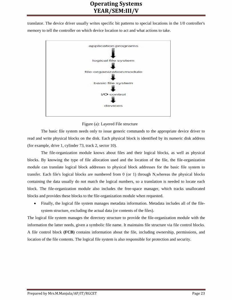
The file system itself is generally composed of many different levels. The structure shown in Figure
(a) is an example of a layered design. Each level in the design uses the features of lower levels to create
new features for use by higher levels.
The lowest level, the I/O control, consists of device drivers and interrupts handlers to transfer
information between the main memory and the disk system. A device driver can be thought of as a
Operating Systems YEAR/SEM:III/V
Prepared by Mrs.M.Manjula/AP/IT/RGCET Page 23
translator. The device driver usually writes specific bit patterns to special locations in the 1/0 controller's
memory to tell the controller on which device location to act and what actions to take.
Figure (a): Layered File structure
The basic file system needs only to issue generic commands to the appropriate device driver to
read and write physical blocks on the disk. Each physical block is identified by its numeric disk address
(for example, drive 1, cylinder 73, track 2, sector 10).
The file-organization module knows about files and their logical blocks, as well as physical
blocks. By knowing the type of file allocation used and the location of the file, the file-organization
module can translate logical block addresses to physical block addresses for the basic file system to
transfer. Each file's logical blocks are numbered from 0 (or 1) through N,whereas the physical blocks
containing the data usually do not match the logical numbers, so a translation is needed to locate each
block. The file-organization module also includes the free-space manager, which tracks unallocated
blocks and provides these blocks to the file-organization module when requested.
Finally, the logical file system manages metadata information. Metadata includes all of the file-
system structure, excluding the actual data (or contents of the files).
The logical file system manages the directory structure to provide the file-organization module with the
information the latter needs, given a symbolic file name. It maintains file structure via file control blocks.
A file control block (FCB) contains information about the file, including ownership, permissions, and
location of the file contents. The logical file system is also responsible for protection and security.

Operating Systems YEAR/SEM:III/V
Prepared by Mrs.M.Manjula/AP/IT/RGCET Page 24
FILE-SYSTEM IMPLEMENTATION
Operating systems implement open and close systems calls for processes to request access to file contents.
Overview
Several on-disk and in-memory structures are used to implement a file system. These vary
depending on the operating system and the file system, but some general principles apply.
On-disk, the file system may contain information about how to boot an operating system stored
there, the total number of blocks, the number and location of free blocks, the directory structure, and
individual files.
A boot control block can contain information needed by the system to boot an operating from
that partition. If the disk does not contain an operating system, this block can be empty. It is typically the
first block of a partition.
In UFS, this is called the boot block; in NTFS, it is the partition boot sector. A partition control block
contains partition details, such as the number of blocks in the partition, size of the blocks, free-block
count and free-block pointers, and free FCB count and FCB pointers. In UFS this is called a superblock;
in NTFS, it is the Master File Table. A directory structure is used to organize the files
An FCB contains many of the file's details, including file permissions, ownership, size, and
location of the data blocks. In UFS this is called the inode. In NTFS, this information is actually stored
within the Master File Table, which uses a relational database structure, with a row per file.
The in-memory information is used for both file-system management and performance
improvement via caching.
The structures can include:
An in-memory partition table containing information about each mounted partition. An in-
memory directory structure that holds the directory information of recently accessed directories. (For
directories at which partitions are mounted, it can contain a pointer to the partition table.)
The system-wide open-file table contains a copy of the FCB of each open file, as well as other
information.
The per-process open-file table contains a pointer to the appropriate entry in the system-wide
open-file table, as well as other information.
To create a new file, an application program calls the logical file system. The logical file system
knows the format of the directory structures. To create a new file, it allocates a new FCB, reads the
appropriate directory into memory, updates it with the new file name and FCB, and writes it back to the
disk. A typical FCB is shown in Figure (b).

Operating Systems YEAR/SEM:III/V
Prepared by Mrs.M.Manjula/AP/IT/RGCET Page 25
Figure (b): Typical File control Block
When a process closes the file, the per-process table entry is removed, and the system-wide
entry's open count is decremented. When all users that have opened the file close it, the updated file
information is copied back to the disk-based directory structure and the system-wide open-file table entry
is removed.
In reality, the open system call first searches the system-wide open-file table to see if the file is
already in use by another process. If it is, a per-process open-file table entry is created pointing to the
existing system-wide open-file table. This algorithm can save substantial overhead when opening files
that are already open. The operating structures of a file-system implementation are summarized in Figure
(c).
Partitions and Mounting
A disk can be sliced into multiple partitions, or a partition can span multiple disks. The former is
discussed here. Each partition can either be "raw," containing no file system, or "cooked," containing a
file system. Raw disk is used where no file system is appropriate. Boot information can be stored in a
separate partition. Again, it has its own format, because at boot time the system does not have file-system
device drivers loaded and therefore cannot interpret the file-system format. Rather, it is usually a
sequential series of blocks, loaded as an image into memory. Execution of the image starts at a predefined
location, such as the first byte. This boot image can contain more than the instructions for how to boot a
specific operating system.
Dual-booted
Multiple operating systems can be installed on such a system. A boot loader that understands
multiple file systems and multiple operating systems can occupy the boot space. Once loaded, it can boot
one of the operating systems available on the disk. The disk can have multiple partitions, each containing
a different type of file system and a different operating system.

Operating Systems YEAR/SEM:III/V
Prepared by Mrs.M.Manjula/AP/IT/RGCET Page 26
Root partition
It contains the operating-system kernel and potentially other system files, is mounted at boot time. Other
partitions can be automatically mounted at boot or manually mounted later, depending on the operating
system. The operating system notes in its in-memory mount table structure that a file system is mounted,
and the type of the file system. The details of this function depend on the operating system.
Figure (c): In-memory file system structure (a) File open (b) File read
Virtual File Systems
While the previous section makes it clear that modern operating systems must support
concurrently multiple types of file systems.
Data structures and procedures are used to isolate the basic system call functionality from the
implementation details. Thus, the file-system implementation consists of three major layers; it is depicted
schematically in Figure (d).
The first layer is the file-system interface, based on the open, read, write, and close calls, and file
descriptors.
The second layer is called the Virtual File System (VFS) layer; it serves two important
functions:

Operating Systems YEAR/SEM:III/V
Prepared by Mrs.M.Manjula/AP/IT/RGCET Page 27
Figure (d): Schematic view of virtual file system
1. It separates file-system-generic operations from their implementation by defining a clean VFS
interface. Several implementations for the VFS interface may coexist on the same machine, allowing
transparent access to different types of file systems mounted locally.
The VFS is based on a file-representation structure, called a v-node, that contains a numerical designator
for a network-wide unique file. (UNIX inodes are unique within only a single file system.) This network-
wide uniqueness is required for support of network file systems. The kernel maintains one v-node
structure for each active node (file or directory). Thus, the VFS distinguishes local files from remote ones,
and local files are further distinguished according to their file-system types.
DIRECTORY IMPLEMENTATION
The selection of directory-allocation and directory-management algorithms has a large effect on
the efficiency, performance, and reliability of the file system. Two algorithms are linear and hash table
algorithm.
Linear List
The simplest method of implementing a directory is to use a linear list of file names with pointers
to the data blocks. A linear list of directory entries requires a linear search to find a particular entry. This
method is simple to program but time-consuming to execute. To create a new file, we must first search the
directory to be sure that no existing file has the same name. Then, we add a new entry at the end of the
directory. To delete a file, we search the directory for the named file, then release the space allocated to it.
To reuse the directory Entry: mark the entry as unused (by assigning it a special name, such as an
all-blank name, or with a used-unused bit in each entry)
Attach it to a list of free directory entries.

Operating Systems YEAR/SEM:III/V
Prepared by Mrs.M.Manjula/AP/IT/RGCET Page 28
Copy the last entry in the directory into the freed location, and to decrease the length of the
directory. A linked list can also be used to decrease the time to delete a file.
Disadvantage:
Through linear search it takes time to search a file.
Directory information is used frequently, and users would notice a slow implementation of access
to it.Many operating systems implement a software cache to store the most recently used directory
information. A cache hit avoids constantly rereading the information from disk.
A sorted list allows a binary search and decreases the average search time.
Hash Table
Another data structure that has been used for a file directory is a hash table. In this method, a
linear list stores the directory entries, but a hash data structure is also used. The hash table takes a value
computed from the file name and returns a pointer to the file name in the linear list. Therefore, it can
greatly decrease the directory search time. Insertion and deletion are also fairly straightforward, although
some provision must be made for collisions-situations where two file names hash to the same location.
The major difficulties with a hash table are its generally fixed size and the dependence of the hash
function on that size.
For example, assume that we make a linear-probing hash table that holds 64 entries. The hash
function converts file names into integers from 0 to 63, for instance, by using the remainder of a division
by 64. If we later try to create a 65th file, we must enlarge the directory hash table-say, to 128 entries. As
a result, we need a new hash function that must map file names to the range 0 to 127, and we must
reorganize the existing directory entries to reflect their new hash-function values. Alternately, a chained-
overflow hash table can be used.
ALLOCATION METHODS
The direct-access nature of disks allows us flexibility in the implementation of files. In almost
every case, many files will be stored on the same disk. The main problem is how to allocate space to these
files so that disk space is utilized effectively and files can be accessed quickly. Three major methods of
allocating disk space are in wide use: contiguous, linked, and indexed. Each method has advantages and
disadvantages.
Contiguous Allocation
The contiguous-allocation method requires each file to occupy a set of contiguous blocks on the
disk. Disk addresses define a linear ordering on the disk. With this ordering, assuming that only one job is
accessing the disk, accessing block b + 1 after block b normally requires no head movement. The IBM
VM/CMS operating system uses contiguous allocation because it provides such good performance.

Operating Systems YEAR/SEM:III/V
Prepared by Mrs.M.Manjula/AP/IT/RGCET Page 29
Contiguous allocation of a file is defined by the disk address and length (in block units) of the
first block. If the file is n blocks long and starts at location b, then it occupies blocks b, b + 1, b + 2, ..., b
+ n - 1. The directory entry for each file indicates the address of the starting block and the length of the
area allocated for this file (Figure a).
Accessing a file that has been allocated contiguously is easy. For sequential access, the file
system remembers the disk address of the last block referenced and, when necessary, reads the next block.
For direct access to block i of a file that starts at block b, we can immediately access block b + i. Thus,
both sequential and direct access can be supported by contiguous allocation.
Figure: (a) Contiguous allocation of disk space.
Contiguous allocation has some problems, however. One difficulty is finding space for a new file.
The contiguous disk-space-allocation problem can be seen to be a particular application of the general
dynamic storage-allocation problem. i.e . which is how to satisfy a request of size n from a list of free
holes.
First fit and best fit are the most common strategies used to select a free hole from the set of
available holes. Simulations have shown that both first fit and best fit are more efficient than worst fit in
terms of both time and storage utilization. These algorithms suffer from the problem of external
fragmentation. As files are allocated and deleted, the free disk space is broken into little pieces. External
fragmentation exists whenever free space is broken into chunks. It becomes a problem when the largest
contiguous chunk is insufficient for a request; storage is fragmented into a number of holes, no one of
which is large enough to store the data. The external fragmentation can be effectively compacts all free
space into one contiguous space, solving the fragmentation problem.

Operating Systems YEAR/SEM:III/V
Prepared by Mrs.M.Manjula/AP/IT/RGCET Page 30
Another problem with contiguous allocation is determining how much space is needed for a file.
When the file is created, the total amount of space it will need must be found and allocated. in general,
however, the size of an output file may be difficult to estimate. If we allocate too little space to a file, we
may find that the file cannot be extended. Especially with a best-fit allocation strategy, the space on both
sides of the file may be in use. Hence, we cannot make the file larger in place.
Two possibilities then exist. First, the user program can be terminated, with an appropriate error message.
The user must then allocate more space and run the program again. These repeated runs may be costly. To
prevent them, the user will normally overestimate the amount of space needed, resulting in considerable
wasted space.
The other possibility is to find a larger hole, copy the contents of the file to the new space, and
release the previous space. This series of actions may be repeated as long as space exists, although it can
be time-consuming.
Even if the total amount of space needed for a file is known in advance, pre-allocation may be
inefficient. A file that grows slowly over a long period (months or years) must be allocated enough space
for its final size, even though much of that space may be unused for a long time. The file, therefore, has a
large amount of internal fragmentation.
To minimize these drawbacks, some operating systems use a modified contiguous-allocation
scheme, in which a contiguous chunk of space is allocated initially, and then, when that amount is not
large enough, another chunk of contiguous space, an extent, is added to the initial allocation. The location
of a file's blocks is then recorded as a location and a block count, plus a link to the first block of the next
extent.
Linked Allocation
Linked allocation solves all problems of contiguous allocation. With linked allocation, each file is
a linked list of disk blocks; the disk blocks may be scattered anywhere on the disk. The directory contains
a pointer to the first and last blocks of the file. For example, a file of five blocks might start at block 9,
continue at block 16, then block 1, block 10, and finally block 25 (Figure (b)).Each block contains a
pointer to the next block. These pointers are not made available to the user. Thus, if each block is 512
bytes, and a disk address (the pointer) requires 4 bytes, then the user sees blocks of 508 bytes.
To create a new file, we simply create a new entry in the directory. With linked allocation, each directory
entry has a pointer to the first disk block of the file. This pointer is initialized to nil (the end-of-list pointer
value) to signify an empty file. The size field is also set to 0. A write to the file causes a free block to be
found via the free-space-management system, and this new block is then written to, and is linked to the
end of the file. To read a file, we simply read blocks by following the pointers from block to block. There
is no external fragmentation with linked allocation, and any free block on the free-space list can be used
to satisfy a request. A file can continue to grow as long as free blocks are available. Linked allocation
does have disadvantages, however. The major problem is that it can be used effectively only for
sequential-access files. To find the ith
block of a file, we must start at the beginning of that file, and follow

Operating Systems YEAR/SEM:III/V
Prepared by Mrs.M.Manjula/AP/IT/RGCET Page 31
the pointers until we get to the ith
block. Each access to a pointer requires a disk read, and sometimes a
disk seek. Consequently, it is inefficient to support a direct-access capability for linked allocation files.
Figure (b): Linked allocation of disk space.
Figure (c): File-allocation table.
Another disadvantage to linked allocation is the space required for the pointers. If a pointer
requires 4 bytes out of a 512-byte block, then 0.78 percent of the disk is being used for pointers, rather
than for information. The usual solution to this problem is to collect blocks into multiples, called clusters,
and to allocate the clusters rather than blocks. For instance, the file system may define a cluster as 4
blocks, and operate on the disk in only cluster units. Pointers then use a much smaller percentage of the
Operating Systems YEAR/SEM:III/V
Prepared by Mrs.M.Manjula/AP/IT/RGCET Page 32
file's disk space. This method improves disk throughput and decreases the space needed for block
allocation and free-list management. The cost of this approach is an increase in internal fragmentation,
because more space is wasted if a cluster is partially full than when a block is partially full. Clusters can
be used to improve the disk-access time for many other algorithms, so they are used in most operating
systems.
Yet another problem of linked allocation is reliability. Since the files are linked together by
pointers scattered all over the disk, consider what would happen if a pointer were lost or damaged. A bug
in the operating-system software or a disk hardware failure might result in picking up the wrong pointer.
This error could result in linking into the free-space list or into another file. Partial solutions are to use
doubly linked lists or to store the file name and relative block number in each block; however, these
schemes require even more overhead for each file.
An important variation on the linked allocation method is the use of a file allocation table (FAT).
This simple but efficient method of disk-space allocation is used by the MS-DOS and OS/2 operating
systems. A section of disk at the beginning of each partition is set aside to contain the table. The table has
one entry for each disk block, and is indexed by block number. The FAT is used much as is a linked list.
The directory entry contains the block number of the first block of the file. The table entry indexed by that
block number then contains the block number of the next block in the file. This chain continues until the
last block, which has a special end-of-file value as the table entry. Unused blocks are indicated by a 0
table value. Allocating a new block to a file is a simple matter of finding the first 0-valued table entry, and
replacing the previous end-of-file value with the address of the new block. The 0 is then replaced with the
end-of-file value. An illustrative example is the FAT structure of Figure (c) for a file consisting of disk
blocks 217,618, and 339. The FAT allocation scheme can result in a significant number of disk head
seeks, unless the FAT is cached. A benefit is that random access time is improved, because the disk head
can find the location of any block by reading the information in the FAT.
Indexed Allocation
Linked allocation solves the external-fragmentation and size-declaration problems of contiguous
allocation. However, in the absence of a FAT, linked allocation cannot support efficient direct access,
since the pointers to the blocks are scattered with the blocks themselves all over the disk and need to be
retrieved in order, Indexed allocation solves this problem by bringing all the pointers together into one
location: the index block.
Each file has its own index block, which is an array of disk-block addresses.The ith entry in the
index block points to the ith block of the file. The directory contains the address of the index block
(Figure (d)). To read the ith block, we use the pointer in the ith index-block entry to find and read the
desired block.
When the file is created, all pointers in the index block are set to nil. When the ith block is first
written, a block is obtained from the free-space manager, and its address is put in the ith index-block
entry. Indexed allocation supports direct access, without suffering from external fragmentation, because

Operating Systems YEAR/SEM:III/V
Prepared by Mrs.M.Manjula/AP/IT/RGCET Page 33
any free block on the disk may satisfy a request for more space. Indexed allocation does suffer from
wasted space. The pointer overhead of the index block is generally greater than the pointer overhead of
linked allocation.
This point raises the question of how large the index block should be. Every file must have an
index block, so we want the index block to be as small as possible. If the index block is too small,
however, it will not be able to hold enough pointers for a large file, and a mechanism will have to be
available to deal with this issue:
Linked scheme: An index block is normally one disk block. Thus, it can be read and written directly by
itself. To allow for large files, we may link together several index blocks. For example, an index block
might contain a small header giving the name of the file, and a set of the first 100 disk-block addresses.
The next address (the last word in the index block) is nil (for a small file) or is a pointer to another index
block (for a large file).
Figure(d): Indexed allocation of disk space
Multilevel index: A variant of the linked representation is to use a firstlevel index block to point to a set
of second-level index blocks, which in turn point to the file blocks. To access a block, the operating
system uses the first-level index to find a second-level index block, and that block to find the desired data
block. This approach could be continued to a third or fourth level, depending on the desired maximum file
size.

Operating Systems YEAR/SEM:III/V
Prepared by Mrs.M.Manjula/AP/IT/RGCET Page 34
Combined scheme: Another alternative, used in the UFS, is to keep the first, say, 15 pointers of the
index block in the file's inode. The first 12 of these pointers point to direct blocks; that is, they contain
addresses of blocks that contain data of the file. Thus, the data for small (no more than 12 blocks) files do
not need a separate index block. The next 3 pointers point to indirect blocks. The first indirect block
pointer is the address of a single indirect block. The single indirect block is an index block, containing not
data, but rather the addresses of blocks that do contain data. Then there is a double indirect block pointer,
which contains the address of a block that contains the addresses of blocks that contain pointers to the
actual data blocks. The last pointer would contain the address of a triple indirect block. Under this
method, the number of blocks that can be allocated to a file exceeds the amount of space address
allocated.
Figure (e): The UNIX inode.
FREE-SPACE MANAGEMENT
Since disk space is limited, we need to reuse the space from deleted files for new files, if possible.
To keep track of free disk space, the system maintains a free-space list. The free-space list records all
free disk blocks-those not allocated to some file or directory. To create a file, we search the free-space list
for the required amount of space, and allocate that space to the new file. This space is then removed from
the free-space list. When a file is deleted, its disk space is added to the free-space list. The free-space list,
despite its name, might not be implemented as a list, as we shall discuss.
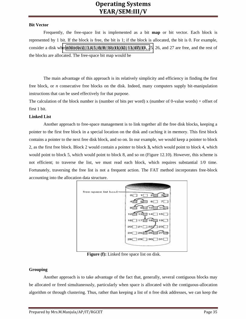
Operating Systems YEAR/SEM:III/V
Prepared by Mrs.M.Manjula/AP/IT/RGCET Page 35
Bit Vector
Frequently, the free-space list is implemented as a bit map or bit vector. Each block is
represented by 1 bit. If the block is free, the bit is 1; if the block is allocated, the bit is 0. For example,
consider a disk where blocks 2, 3,4,5, 8, 9, 10, 11, 12, 13, 17, 18, 25, 26, and 27 are free, and the rest of
the blocks are allocated. The free-space bit map would be
The main advantage of this approach is its relatively simplicity and efficiency in finding the first
free block, or n consecutive free blocks on the disk. Indeed, many computers supply bit-manipulation
instructions that can be used effectively for that purpose.
The calculation of the block number is (number of bits per word) x (number of 0-value words) + offset of
first 1 bit.
Linked List
Another approach to free-space management is to link together all the free disk blocks, keeping a
pointer to the first free block in a special location on the disk and caching it in memory. This first block
contains a pointer to the next free disk block, and so on. In our example, we would keep a pointer to block
2, as the first free block. Block 2 would contain a pointer to block 3, which would point to block 4, which
would point to block 5, which would point to block 8, and so on (Figure 12.10). However, this scheme is
not efficient; to traverse the list, we must read each block, which requires substantial 1/0 time.
Fortunately, traversing the free list is not a frequent action. The FAT method incorporates free-block
accounting into the allocation data structure.
Figure (f): Linked free space list on disk.
Grouping
Another approach is to take advantage of the fact that, generally, several contiguous blocks may
be allocated or freed simultaneously, particularly when space is allocated with the contiguous-allocation
algorithm or through clustering. Thus, rather than keeping a list of n free disk addresses, we can keep the

Operating Systems YEAR/SEM:III/V
Prepared by Mrs.M.Manjula/AP/IT/RGCET Page 36
address of the first free block and the number n of free contiguous blocks that follow the first block. Each
entry in the free-space list then consists of a disk address and a count.
KERNEL I/O SUBSYSTEM
Kernels provide many services related to I/O. Several services-scheduling, buffering, caching,
spooling, device reservation, and error handling-are provided by the kernel's I/O subsystem and build on
the hardware and device driver infrastructure.
I/0 Scheduling
To schedule a set of I/O requests means to determine a good order in which to execute them. The
order in which applications issue system calls rarely is the best choice. Scheduling can improve overall
system performance, can share device access fairly among processes, and can reduce the average waiting
time for 1/0 to complete. Here is a simple example to illustrate Application 1 requests a block near the
end of the disk, application 2 requests one near the beginning, and application 3 requests one in the
middle of the disk. The operating system can reduce the distance that the disk arm travels by serving the
applications in order 2, 3, 1. Rearranging the order of service in this way is the essence of I/O scheduling.
When an application issues a blocking I/O system call, the request is placed on the queue for that device.
The I/O scheduler rearranges the order of the queue to improve the overall system efficiency and the
average response time experienced by applications.
Buffering
A buffer is a memory area that stores data while they are transferred between two devices or
between a device and an application. Buffering is done for three reasons. One reason is to cope with a
speed mismatch between the producer and consumer of a data stream. Suppose, for example, that a file is
being received via modem for storage on the hard disk. The modem is about a thousand times slower than
the hard disk. So a buffer is created in main memory to accumulate the bytes received from the modem.
When an entire buffer of data has arrived, the buffer can be written to disk in a single operation. Since the
disk write is not instantaneous and the modem still needs a place to store additional incoming data, two
buffers are used. After the modem fills the first buffer, the disk write is requested. The modem then starts
to fill the second buffer while the first buffer is written to disk. By the time the modem has filled the
second buffer, the disk write from the first one should have completed, so the modem can switch back to
the first buffer while the disk writes the second one. This double buffering decouples the producer of
data from the consumer, thus relaxing timing requirements between them. The need for this decoupling is
illustrated in Figure (a).
A second use of buffering is to adapt between devices that have different data-transfer sizes. Such
disparities are especially common in computer networking, where buffers are used widely for
fragmentation and reassembly of messages. At the sending side, a large message is fragmented into small
network packets. The packets are sent over the network, and the receiving side places them in a
reassembly buffer to form an image of the source data.

Operating Systems YEAR/SEM:III/V
Prepared by Mrs.M.Manjula/AP/IT/RGCET Page 37
A third use of buffering is to support copy semantics for application I/O. An example will clarify the
meaning of "copy semantics." Suppose that an application has a buffer of data that it wishes to write to
disk. It calls the write () system call, providing a pointer to the buffer and an integer specifying the
number of bytes to write. A simple way that the operating system can guarantee copy semantics is for the
write () system call to copy the application data into a kernel buffer before returning control to the
application. The disk write is performed from the kernel buffer, so that subsequent changes to the
application buffer have no effect. Copying of data between kernel buffers and application data space is
common in operating systems, despite the overhead that this operation introduces, because of the clean
semantics.
Caching
A cache is a region of fast memory that holds copies of data. Access to the cached copy is more
efficient than access to the original. For instance, the instructions of the currently running process are
stored on disk, cached in physical memory, and copied again in the CPU's secondary and primary caches.
The difference between a buffer and a cache is that a buffer may hold the only existing copy of a data
item, whereas a cache, by definition, just holds a copy on faster storage of an item that resides elsewhere.
Caching and buffering are distinct functions, but sometimes a region of memory can be used for both
purposes. For instance, to preserve copy semantics and to enable efficient scheduling of disk I/O, the
operating system uses buffers in main memory to hold disk data. These buffers are also used as a cache,
to improve the I/O efficiency for files that are shared by applications or that are being written and reread
rapidly. When the kernel receives a file I/O request, the kernel first accesses the buffer cache to see
whether that region of the file is already available in main memory. If so, a physical disk I/O can be
avoided or deferred.
Spooling and Device Reservation
A spool is a buffer that holds output for a device, such as a printer, that cannot accept interleaved
data streams. Although a printer can serve only one job at a time, several applications may wish to print
their output concurrently, without having their output mixed together. The operating system solves this
problem by intercepting all output to the printer. Each application's output is spooled to a separate disk
file. When an application finishes printing, the spooling system queues the corresponding spool file for
output to the printer. The spooling system copies the queued spool files to the printer one at a time. In
some operating systems, spooling is managed by a system daemon process. In other operating systems, it
is handled by an in-kernel thread. In either case, the operating system provides a control interface that
enables users and system administrators to display the queue, to remove unwanted jobs before those jobs
print, to suspend printing while the printer is serviced, and so on.
Error Handling
An operating system that uses protected memory can guard against many kinds of hardware and
application errors, so that a complete system failure is not the usual result. Devices and 1/0 transfers can
fail in many ways, either for transient reasons, such as a network becoming overloaded, or for

Operating Systems YEAR/SEM:III/V
Prepared by Mrs.M.Manjula/AP/IT/RGCET Page 38
"permanent" reasons, such as a disk controller becoming defective. Operating systems can often
compensate effectively for transient failures. For instance, a disk read() failure results in a read() retry,
and a network send () error results in a resend (), if the protocol so specifies. As a general rule, an I/O
system call will return 1 bit of information about the status of the call, signifying either success or failure.
In the UNIX operating system, an additional integer variable named errno is used to return an error code-
one of about 100 values-indicating the general nature of the failure.
For instance, a failure of a SCSI device is reported by the SCSI protocol in terms of a sense key
that identifies the general nature of the failure, such as a hardware error or an illegal request; an
additional sense code that states the category of failure, such as a bad command parameter or a self-test
failure; and an additional sense-code qualifier that gives even more detail, such as which command
parameter was in error, or which hardware subsystem failed its self-test.
Kernel Data Structures
The kernel needs to keep state information about the use of I/O components. It does so through a
variety of in-kernel data structures, such as the open-file table structure. UNIX provides file-system
access to a variety of entities, such as user files, raw devices, and the address spaces of processes.
Although each of these entities supports a read () operation, the semantics differ. To read a raw disk, the
kernel needs to ensure that the request size is a multiple of the disk sector size, and is aligned on a sector
boundary. To read a process image, it is merely necessary to copy data from memory. UNIX encapsulates
these differences within a uniform structure by using an object-oriented technique. The open-file record,
shown in Figure (b), contains a dispatch table that holds pointers to the appropriate routines, depending
on the type of file.
Some operating systems use object-oriented methods even more extensively. For instance,
Windows NT uses a message-passing implementation for I/O. An 1/0 request is converted into a message
that is sent through the kernel to the I/O manager and then to the device driver, each of which may change
the message contents. For output, the message contains the data to be written. For input, the message
contains a buffer to receive the data.
Disk Structure
Disks provide the bulk of secondary storage for modern computer systems. Magnetic tape was
used as an early secondary-storage medium, but the access time is much slower than for disks. Thus, tapes
are currently used mainly for backup, for storage of infrequently used information, as a medium for
transferring information from one system to another, and for storing quantities of data so large that they
are impractical as disk systems. Modern disk drives are addressed as large one-dimensional arrays of
logical blocks, where the logical block is the smallest unit of transfer. The size of a logical block is
usually 512 bytes, although some disks can be low-level formatted to choose a different logical block
size, such as 1,024 bytes.
The one-dimensional array of logical blocks is mapped onto the sectors of the disk sequentially.
Sector 0 is the first sector of the first track on the outermost cylinder. The mapping proceeds in order

Operating Systems YEAR/SEM:III/V
Prepared by Mrs.M.Manjula/AP/IT/RGCET Page 39
through that track, then through the rest of the tracks in that cylinder, and then through the rest of the
cylinders from outermost to innermost. By using this mapping, we can theory-convert a logical block
number into an old-style disk address that consists of a cylinder number, a track number within that
cylinder, and a sector number within that track.
In practice, it is difficult to perform this translation, for two reasons.
First, most disks have some defective sectors, but the mapping hides this by substituting spare
sectors from elsewhere on the disk.
Second, the number of sectors per track is not a constant on some drives.
Constant linear velocity (CLV), the density of bits per track is uniform. The farther a track is from the
center of the disk, the greater its length, so the more sectors it can hold. As we move from outer zones to
inner zones, the number of sectors per track decreases. This method is used in CD-ROM and DVD-ROM
drives.
Constant angular velocity (CAV):
Alternatively, the disk rotation speed can stay constant, and the density of bits decreases from inner tracks
to outer tracks to keep the data rate constant. This method is used in hard disks and is known as constant
angular velocity (CAV).
DISK SCHEDULING
One of the responsibilities of the operating system is to use the hardware efficiently. For the disk
drives, meeting this responsibility entails having a fast access time and disk bandwidth. The access time
has two major components.
The seek time is the time for the disk arm to move the heads to the cylinder containing the
desired sector.The rotational latency is the additional time waiting for the disk to rotate the desired
sector to the disk head.The disk bandwidth is the total number of bytes transferred, divided by the total
time between the first request for service and the completion of the last transfer. We can improve both the
access time and the bandwidth by scheduling the servicing of disk I/O requests in a good order.
Whenever a process needs 1/0 to or from the disk, it issues a system call to the operating system.
The request specifies several pieces of information:
Whether this operation is input or output
What the disk address for the transfer is
What the memory address for the transfer is
What the number of bytes to be transferred is
FCFS Scheduling
The simplest form of disk scheduling is, of course, the first-come, first-served (FCFS)
algorithm. This algorithm is intrinsically fair, but it generally does not provide the fastest service.
Consider, for example, a disk queue with requests for 1/0 to blocks on cylinders

Operating Systems YEAR/SEM:III/V
Prepared by Mrs.M.Manjula/AP/IT/RGCET Page 40
in that order. If the disk head is initially at cylinder 53, it will first move from 53 to 98, then to 183, 37,
122, 14, 124, 65, and finally to 67, for a total head movement of 640 cylinders. This schedule is
diagrammed in Figure (a). The wild swing from 122 to 14 and then back to 124 illustrates the problem
with this schedule. If the requests for cylinders 37 and 14 could be serviced together, before or after the
requests at 122 and 124, the total head movement could be decreased substantially, and performance
could be thereby improved.
Figure (a):FCFS disk scheduling.
SSTF Scheduling
It seems reasonable to service all the requests close to the current head position, before moving
the head far away to service other requests. This assumption is the basis for the shortest-seek-time-first
(SSTF) algorithm. The SSTF algorithm selects the request with the minimum seek time from the current
head position. Since seek time increases with the number of cylinders traversed by the head, SSTF
chooses the pending request closest to the current head position.

Operating Systems YEAR/SEM:III/V
Prepared by Mrs.M.Manjula/AP/IT/RGCET Page 41
For our example request queue, the closest request to the initial head position (53) is at cylinder 65. Once
we are at cylinder 65, the next closest request is at cylinder 67. From there, the request at cylinder 37 is
closer than 98, so 37 is served next. Continuing, we service the request at cylinder 14, then 98, 122, 124,
and finally 183 (Figure 14.2). This scheduling method results in a total head movement of only 236
cylinders-little more than one-third of the distance needed for FCFS scheduling of this request queue.
This algorithm gives a substantial improvement in performance.
SSTF scheduling is essentially a form of shortest-job-first (SJF) scheduling, and, like SJF
scheduling, it may cause starvation of some requests. Remember that requests may arrive at any time.
Suppose that we have two requests in the queue, for cylinders 14 and 186, and while servicing the request
from 14, a new request near 14 arrives. This new request will be serviced next, making the request at 186
wait. While this request is being serviced, another request close to 14 could arrive. In theory, a continual
stream of requests near one another could arrive, causing the request for cylinder 186 to wait indefinitely.
This scenario becomes increasingly likely if the pending-request queue grows long. Although the SSTF
algorithm is a substantial improvement over the FCFS algorithm, it is not optimal.
Figure (b):SSTF disk scheduling.
SCAN Scheduling
In the SCAN algorithm, the disk arm starts at one end of the disk, and moves toward the other
end, servicing requests as it reaches each cylinder, until it gets to the other end of the disk. At the other
end, the direction of head movement is reversed, and servicing continues. The head continuously scans
back and forth across the disk. We again use our example. Before applying SCAN to schedule the
requests on cylinders 98, 183, 37, 122, 14, 124, 65, and 67, we need to know the direction of head
movement, in addition to the head's current position (53). If the disk arm is moving toward 0, the head
will service 37 and then 14. At cylinder 0, the arm will reverse and will move toward the other end of the
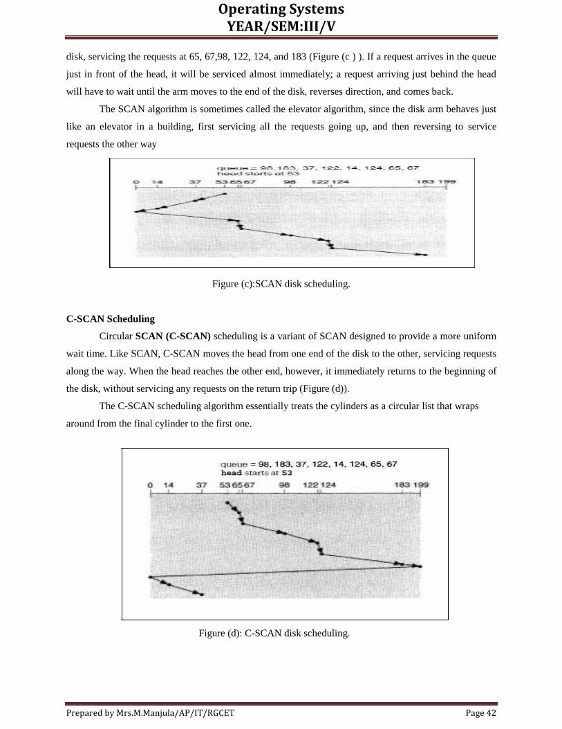
Operating Systems YEAR/SEM:III/V
Prepared by Mrs.M.Manjula/AP/IT/RGCET Page 42
disk, servicing the requests at 65, 67,98, 122, 124, and 183 (Figure (c ) ). If a request arrives in the queue
just in front of the head, it will be serviced almost immediately; a request arriving just behind the head
will have to wait until the arm moves to the end of the disk, reverses direction, and comes back.
The SCAN algorithm is sometimes called the elevator algorithm, since the disk arm behaves just
like an elevator in a building, first servicing all the requests going up, and then reversing to service
requests the other way
Figure (c):SCAN disk scheduling.
C-SCAN Scheduling
Circular SCAN (C-SCAN) scheduling is a variant of SCAN designed to provide a more uniform
wait time. Like SCAN, C-SCAN moves the head from one end of the disk to the other, servicing requests
along the way. When the head reaches the other end, however, it immediately returns to the beginning of
the disk, without servicing any requests on the return trip (Figure (d)).
The C-SCAN scheduling algorithm essentially treats the cylinders as a circular list that wraps
around from the final cylinder to the first one.
Figure (d): C-SCAN disk scheduling.

Operating Systems YEAR/SEM:III/V
Prepared by Mrs.M.Manjula/AP/IT/RGCET Page 43
LOOK Scheduling
As we described them, both SCAN and C-SCAN move the disk arm across the full width of the
disk. In practice, neither algorithm is implemented this way. More commonly, the arm goes only as far as
the final request in each direction. Then, it reverses direction immediately, without going all the way to
the end of the disk. These versions of SCAN and C-SCAN are called LOOK and C-LOOK scheduling,
because they look for a request before continuing to move in a given direction (Figure (e)).
Fig:C-LOOK disk scheduling.
DISK MANAGEMENT
The operating system is responsible for several other aspects of disk management, too. Here we
discuss disk initialization, booting from disk, and bad-block recovery.
Disk Formatting
A new magnetic disk is a blank slate: It is just platters of a magnetic recording material. Before a
disk can store data, it must be divided into sectors that the disk controller can read and write. This process
is called low-level formatting (or physical formatting).
Low-level formatting fills the disk with a special data structure for each sector. The data structure for a
sector typically consists of a header, a data area (usually 512 bytes in size), and a trailer. The header and
trailer contain information used by the disk controller, such as a sector number and an error-correcting
code (ECC). When the controller writes a sector of data during normal I/O, the ECC is updated with a
value calculated from all the bytes in the data area. When the sector is read, the ECC is recalculated and is
compared with the stored value. If the stored and calculated numbers are different, this mismatch
indicates that the data area of the sector has become corrupted and that the disk sector may be bad The
ECC is an error-correcting code because it contains enough information that, if only a few bits of data

Operating Systems YEAR/SEM:III/V
Prepared by Mrs.M.Manjula/AP/IT/RGCET Page 44
have been corrupted, the controller can identify which bits have changed and can calculate what their
correct values should be. The controller automatically does the ECC processing whenever a sector is read
or written. Most hard disks are low-level formatted at the factory as a part of the manufacturing process.
This formatting enables the manufacturer to test the disk and to initialize the mapping from logical block
numbers to defect-free sectors on the disk. For many hard disks, when the disk controller is instructed to
low-level format the disk, it can also be told how many bytes of data space to leave between the header
and trailer of all sectors. It is usually possible to choose among a few sizes, such as 256, 512, and 1,024
bytes (mostly 512 bytes).
To use a disk to hold files, the operating system still needs to record its own data structures on the disk. It
does so in two steps.
The first step is to partition the disk into one or more groups of cylinders. The operating system
can treat each partition as though it were a separate disk. For instance, one partition can hold a
copy of the operating system's executable code, while another holds user files.
The second step is logical formatting (or creation of a file system): In this step, the operating
system stores the initial file-system data structures onto the disk. These data structures may
include maps of free and allocated space (a FAT or inodes) and an initial empty directory.
Some operating systems give special programs the ability to use a disk partition as a large sequential array
of logical blocks, without any file-system data structures. This array is sometimes called the raw disk, and
I/O to this array is termed raw I/O. Raw 1/0 bypasses all the file-system services, such as the buffer cache,
file locking, pre-fetching, space allocation, file names, and directories. We can make certain applications
more efficient by implementing their own special-purpose storage services on a raw partition, but most
applications perform better when they use the regular file-system services.
Boot Block
For a computer to start running-for instance, when it is powered up or rebooted-it needs to have
an initial program to run. This initial bootstrap program tends to be simple. It initializes all aspects of the
system, from CPU registers to device controllers and the contents of main memory, and then starts the
operating system. To do its job, the bootstrap program finds the operating system kernel on disk, loads
that kernel into memory, and jumps to an initial address to begin the operating-system execution.
For most computers, the bootstrap is stored in read-only memory (ROM). This location is
convenient, because ROM needs no initialization and is at a fixed location that the processor can start
executing when powered up or reset. And, since ROM is read only, it cannot be infected by a computer
virus. The problem is that changing this bootstrap code requires changing the ROM hardware chips. For
this reason, most systems store a tiny bootstrap loader program in the boot ROM, whose only job is to
bring in a full bootstrap program from disk.The full bootstrap program can be changed easily: A new
version is simply written onto the disk. The full bootstrap program is stored in a partition called the boot
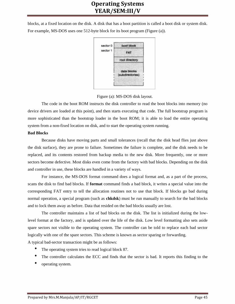
Operating Systems YEAR/SEM:III/V
Prepared by Mrs.M.Manjula/AP/IT/RGCET Page 45
blocks, at a fixed location on the disk. A disk that has a boot partition is called a boot disk or system disk.
For example, MS-DOS uses one 512-byte block for its boot program (Figure (a)).
Figure (a): MS-DOS disk layout.
The code in the boot ROM instructs the disk controller to read the boot blocks into memory (no
device drivers are loaded at this point), and then starts executing that code. The full bootstrap program is
more sophisticated than the bootstrap loader in the boot ROM; it is able to load the entire operating
system from a non-fixed location on disk, and to start the operating system running.
Bad Blocks
Because disks have moving parts and small tolerances (recall that the disk head flies just above
the disk surface), they are prone to failure. Sometimes the failure is complete, and the disk needs to be
replaced, and its contents restored from backup media to the new disk. More frequently, one or more
sectors become defective. Most disks even come from the factory with bad blocks. Depending on the disk
and controller in use, these blocks are handled in a variety of ways.
For instance, the MS-DOS format command does a logical format and, as a part of the process,
scans the disk to find bad blocks. If format command finds a bad block, it writes a special value into the
corresponding FAT entry to tell the allocation routines not to use that block. If blocks go bad during
normal operation, a special program (such as chkdsk) must be run manually to search for the bad blocks
and to lock them away as before. Data that resided on the bad blocks usually are lost.
The controller maintains a list of bad blocks on the disk. The list is initialized during the low-
level format at the factory, and is updated over the life of the disk. Low level formatting also sets aside
spare sectors not visible to the operating system. The controller can be told to replace each bad sector
logically with one of the spare sectors. This scheme is known as sector sparing or forwarding.
A typical bad-sector transaction might be as follows:
The operating system tries to read logical block 87.
The controller calculates the ECC and finds that the sector is bad. It reports this finding to the
operating system.

Operating Systems YEAR/SEM:III/V
Prepared by Mrs.M.Manjula/AP/IT/RGCET Page 46
The next time that the system is rebooted, a special command is run to tell the SCSI controller to
replace the bad sector with a spare.
After that, whenever the system requests logical block 87, the request is translated into the
replacement sector's address by the controller.
When a bad block is remapped, the controller uses a spare sector from the same cylinder, if
possible.
As an alternative to sector sparing, some controllers can be instructed to replace a bad block by
sector slipping. Here is an example: Suppose that logical block 17 becomes defective, and the first
available spare follows sector 202. Then, sector slipping would remap all the sectors from 17 to 202,
moving them all down one spot. That is, sector 202 would be copied into the spare, then sector 201 into
202, and then 200 into 201, and so on, until sector 18 is copied into sector.
SWAP-SPACE MANAGEMENT
Swap-space management is another low-level task of the operating system. Virtual memory
uses disk space as an extension of main memory. Since disk access is much slower than memory access,
using swap space significantly decreases system performance. The main goal for the design and
implementation of swap space is to provide the best throughput for the virtual-memory system.
Swap-Space Use
Swap space is used in various ways by different operating systems, depending on the
implemented memory-management algorithms. For instance, systems that implement swapping may use
swap space to hold the entire process image, including the code and data segments. The amount of swap
space needed on a system can therefore vary depending on the amount of physical memory, the amount of
virtual memory it is backing, and the way in which the virtual memory is used.
Some operating systems, such as UNIX, allow the use of multiple swap spaces. These swap
spaces are usually put on separate disks, so the load placed on the 1/0 system by paging and swapping can
be spread over the system's I/O devices. Note that it is safer to overestimate than to underestimate swap
space, because if a system runs out of swap space it may be forced to abort processes or may crash
entirely. Overestimation wastes disk space that could otherwise be used for files, but does no other harm.
Swap-Space Location
A swap space can reside in two places: Swap space can be carved out of the normal file system,
or it can be in a separate disk partition. If the swap space is simply a large file within the file system,
normal file-system routines can be used to create it, name it, and allocate its space. This approach, though
easy to implement, is also inefficient. Navigating the directory structure and the disk-allocation data
structures takes time and (potentially) extra disk accesses.

Operating Systems YEAR/SEM:III/V
Prepared by Mrs.M.Manjula/AP/IT/RGCET Page 47
External fragmentation can greatly increase swapping times by forcing multiple seeks during
reading or writing of a process image. We can improve performance by caching the block location
information in physical memory, and by using special tools to allocate physically contiguous blocks for
the swap file, but the cost of traversing the file-system data structures still remains.
Alternatively, swap space can be created in a separate disk partition. No file system or directory structure
is placed on this space. Rather, a separate swap-space storage manager is used to allocate and de-allocate
the blocks. This manager uses algorithms optimized for speed, rather than for storage efficiency.
Internal fragmentation may increase, but this tradeoff is acceptable because data in the swap space
generally live for much shorter amounts of time than do files in the file system, and the swap area may be
accessed much more frequently. This approach creates a fixed amount of swap space during disk
partitioning. Some operating systems are flexible and can swap both in raw partitions and in file-system
space. Solaris 2 is an example.
Swap-Space Management: An Example
UNIX started with an implementation of swapping that copied entire processes between
contiguous disk regions and memory. UNIX evolved to a combination of swapping and paging, as paging
hardware became available.
In BSD, swap space is allocated to a process when the process is started. Enough space is set
aside to hold the program, known as the text pages or the text segment, and the data segment of the
process. Pre-allocating all the needed space in this way generally prevents a process from running out of
swap space while it executes. One optimization (for instance, when two users run the same editor) is that
processes with identical text pages share these pages, both in physical memory and in swap space.
Two per-process swap maps are used by the kernel to track swap-space use. The text segment is a fixed
size, so its swap space is allocated in 512 KB chunks, except for the final chunk, which holds the
remainder of the pages, in 1 KB increments (Figure (b)).
Figure (b): 4.3 BSD text-segment swap map.
The data-segment swap map is more complicated, because the data segment can grow over time. The map
is of fixed size, but contains swap addresses for blocks of varying size. Given index i, a block pointed to

Operating Systems YEAR/SEM:III/V
Prepared by Mrs.M.Manjula/AP/IT/RGCET Page 48
by swap-map entry i is of size 2' x 16 KB, to a maximum of 2 MB. This data structure is shown in Figure
(c) ).
When a process tries to grow its data segment beyond the final allocated block in its swap area,
the operating system allocates another block, twice as large as the previous one. This scheme results in
small processes using only small blocks. It also minimizes fragmentation. The blocks of large processes
can be found quickly, and the swap map remains small.
Figure (c): 4.3 BSD data-segment swap map

Operating Systems YEAR/SEM:III/V
Prepared by Mrs.M.Manjula/AP/IT/RGCET Page 49

Operating Systems YEAR/SEM:III/V
Prepared by Mrs.M.Manjula/AP/IT/RGCET Page 50

Operating Systems YEAR/SEM:III/V
Prepared by Mrs.M.Manjula/AP/IT/RGCET Page 51