
OPERATING MANUAL - Sonel2 MRU-30 OPERATING MANUAL version 1.03 The MRU-30 meter is a modern, high...
56
Transcript of OPERATING MANUAL - Sonel2 MRU-30 OPERATING MANUAL version 1.03 The MRU-30 meter is a modern, high...


OPERATING MANUAL
EARTH RESISTANCE METER
MRU-30
SONEL S. A.
Wokulskiego 11 Str.,
58-100 Świdnica, Poland
Version 1.03 April 2017
MRU-30 OPERATING MANUAL version 1.03 2
The MRU-30 meter is a modern, high quality, easy to use and safe measuring device. Please ac-quaint yourself with the present manual in order to avoid measuring errors and prevent possible prob-lems related to operation of the meter.

MRU-30 OPERATING MANUAL version 1.03 3
TABLE OF CONTENTS
1 SAFETY ................................................................................................................... 5
2 TURNING THE METER ON AND ACTIVATING SCREEN BACKLIT. ....... 6
3 METER CONFIGURATION ................................................................................. 6
4 MEASUREMENTS ................................................................................................. 9
4.1 MEASUREMENT OF AC+DC INTERFERING (NOISE) VOLTAGES ................................. 9 4.2 MEASUREMENT OF EARTH CONNECTION AND EQUIPOTENTIAL BONDING (2P) ........ 10 4.3 MEASUREMENT 3P ................................................................................................ 11 4.4 MEASUREMENT 4P ................................................................................................ 14 4.5 MEASUREMENT 3P + CLAMP ................................................................................. 18 4.6 TWO-CLAMP MEASUREMENT ................................................................................. 21 4.7 CALIBRATION OF THE MEASUREMENT CLAMP C-3 ................................................. 23 4.8 MEASUREMENT OF EARTH CONNECTION AND EQUIPOTENTIAL BONDING (200MA) 25 4.9 CALIBRATION OF THE TEST LEADS FOR RCONT MEASUREMENT .............................. 27 4.10 EARTH RESISTIVITY MEASUREMENT ................................................................... 28
5 MEMORY OF MEASUREMENT RESULTS.................................................... 32
5.1 STORING THE MEASUREMENT RESULTS IN THE MEMORY ....................................... 32 5.2 VIEWING MEMORY DATA ....................................................................................... 34 5.3 DELETING MEMORY DATA ..................................................................................... 34
5.3.1 Deleting cell data ........................................................................................... 34 5.3.2 Deleting bank data ......................................................................................... 36 5.3.3 Deleting the whole memory ........................................................................... 37
6 DATA TRANSMISSION ...................................................................................... 39
6.1 COMPUTER CONNECTION ACCESSORIES................................................................. 39 6.2 DATA TRANSMISSION THROUGH USB PORT ........................................................... 39
7 FIRMWARE UPDATE ......................................................................................... 40
8 POWER SUPPLY OF THE METER .................................................................. 40
8.1 MONITORING THE POWER SUPPLY VOLTAGE .......................................................... 40 8.2 CHARGING THE RECHARGEABLE BATTERY PACK ................................................... 41 8.3 GENERAL PRINCIPLES OF USING NI-MH BATTERIES ............................................... 42
9 CLEANING AND MAINTENANCE ................................................................... 43
10 STORAGE ............................................................................................................. 43
11 DISMANTLING AND DISPOSAL ...................................................................... 43

MRU-30 OPERATING MANUAL version 1.03 4
12 TECHNICAL SPECIFICATIONS ....................................................................... 44
12.1 BASIC DATA ........................................................................................................ 44 12.2 ADDITIONAL DATA.............................................................................................. 47
12.2.1 Influence of the serial interference voltage UZ on earth resistance
measurements for functions 3P, 4P, 3P + clamp, ρ .................................... 47 12.2.2 Influence of the auxiliary electrodes on earth resistance measurements for
functions 3P, 4P, 3P + clamp, ρ ................................................................. 47 12.2.3 Influence of the interference current IZ on the result of the earth resistance
measurement 3P+clamp.............................................................................. 47 12.2.4 Influence of interference current on the result of the earth resistance
measurement using double clamps .............................................................. 48 12.2.5 Influence of the relation of the resistance measured with clamp for the
multiple earthing branch to the resultant resistance (3P + clamp) ............ 48 12.2.6 Additional uncertainties in accordance with IEC 61557-5 (3p, 4p) ........... 48
13 ACCESSORIES ..................................................................................................... 49
13.1 STANDARD ACCESSORIES ................................................................................... 49 13.2 ADDITIONAL ACCESSORIES ................................................................................. 49
14 MANUFACTURER ............................................................................................... 50
15 TESTING AND CALIBRATION LABORATORY ........................................... 51

MRU-30 OPERATING MANUAL version 1.03 5
1 Safety
The MRU-30 meter has been designed to carry out measurements which results determine the safety conditions of the installation. Therefore, in order to provide conditions for correct operation and the correctness of the obtained results, the following recommendations must be observed:
Before you proceed to operate the meter, acquaint yourself thoroughly with the present manual and observe the safety regulations and specifications determined by the producer.
The MRU-30 meter has been designed for the purpose of measurements of earth connection and equipotential bonding, and also ground resistivity, Any application that differs from those specified in the present manual may result in a damage to the device and constitute a source of danger for the user.
The device must be operated solely by appropriately qualified personnel with relevant certificates to carry out measurements of electric installation. Operation of the meter realized by unauthor-ized personnel may result in damage to the device and constitute a source of danger for the user.
Using this manual does not exclude the need to comply with occupational health and safety regu-lations and with other relevant fire regulations required during the performance of a particular type of work. Before starting the work with the device in special environments, e.g. potentially fire-risk/explosive environment, it is necessary to consult it with the person responsible for health and safety.
It is unacceptable to operate the following:
A damaged meter which is completely or partially out of order,
A meter with damaged test leads insulation,
A meter stored for an excessive period of time in disadvantageous conditions (e.g. excessive
humidity). If the meter has been transferred from a cool to a warm environment of a
high level of relative humidity, do not start doing measurements until the meter has
been warmed up to the ambient temperature (approximately 30 minutes).
Before measurements may commence, make sure the test leads are connected to the appropri-ate measurement sockets.
The meter can’t be powered from other sources than those mentioned in this manual.
The meter’s inputs are electronically protected from power surge, as a result for example, of ac-cidental connection to the power supply source:
- for all input combinations – up to 276 V for 30 seconds.
Manufacturer’s calibration doesn’t include the resistance of test leads. Displayed result is sum of the measured object and the test leads resistance.
The device complies with the following standards: EN 61010-1 and EN 61557-1, -4, -5.
Note: Manufacturer reserves the right to apply changes in the appearance, accessories and technical parameters of the meter. Due to continuous development of the meter’s software, the actual ap-pearance of the display, in case of some of the functions, may slightly differ from the display pre-sented in this operating manual.
Note:
An attempt to install drivers in 64-bit Windows 8 may result in displaying ‘Installation
failed’ message.
Cause: Windows 8 by default blocks drivers without a digital signature.
Solution: Disable the driver signature enforcement in Windows.
MRU-30 OPERATING MANUAL version 1.03 6
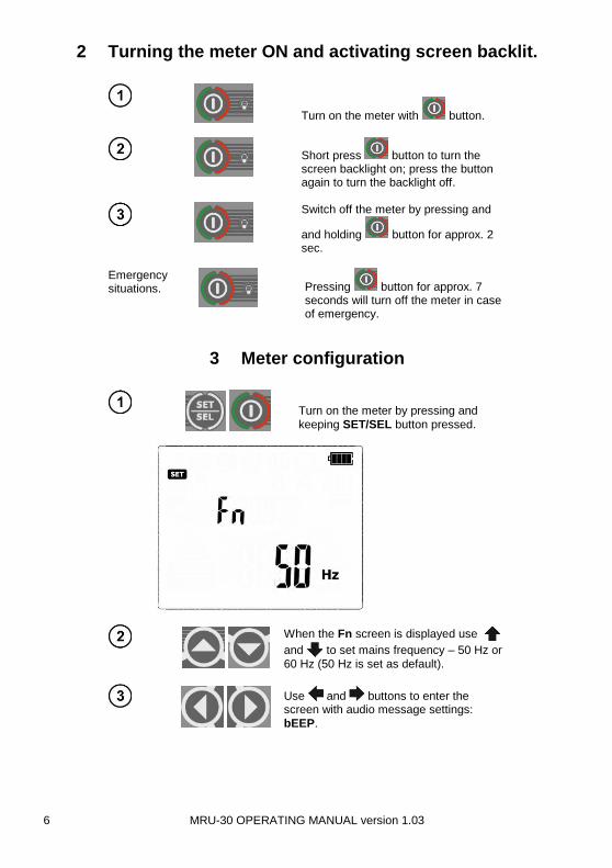
2 Turning the meter ON and activating screen backlit.
Turn on the meter with button.
Short press button to turn the screen backlight on; press the button again to turn the backlight off.
Switch off the meter by pressing and
and holding button for approx. 2 sec.
Emergency situations.
Pressing button for approx. 7 seconds will turn off the meter in case of emergency.
3 Meter configuration
Turn on the meter by pressing and
keeping SET/SEL button pressed.
When the Fn screen is displayed use
and to set mains frequency – 50 Hz or
60 Hz (50 Hz is set as default).
Use and buttons to enter the screen with audio message settings:
bEEP.
MRU-30 OPERATING MANUAL version 1.03 7
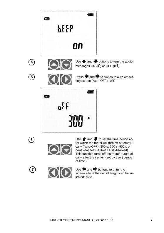
Use and buttons to turn the audio
messages ON ( ) or OFF ( ).
Press and to switch to auto off set-
ting screen (Auto-OFF): oFF
Use and to set the time period af-
ter which the meter will turn off automati-cally (Auto-OFF): 300 s, 600 s, 900 s or none (dashes - Auto-OFF is disabled). This function turns off the meter automati-cally after the certain (set by user) period of time.
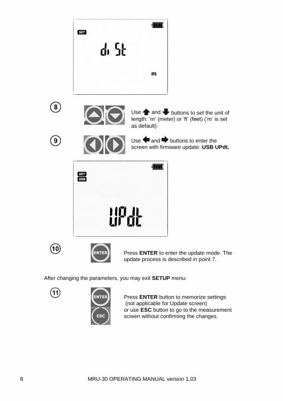
Use and buttons to enter the screen where the unit of length can be se-
lected: diSt.
MRU-30 OPERATING MANUAL version 1.03 8
Use and buttons to set the unit of length: ‘m’ (meter) or ‘ft’ (feet) (‘m’ is set
as default).
Use and buttons to enter the
screen with firmware update: USB UPdt.
Press ENTER to enter the update mode. The update process is described in point 7.
After changing the parameters, you may exit SETUP menu:
Press ENTER button to memorize settings (not applicable for Update screen)
or use ESC button to go to the measurement screen without confirming the changes.

MRU-30 OPERATING MANUAL version 1.03 9
4 Measurements
Note: During measurements the status bar is displayed.
4.1 Measurement of AC+DC interfering (noise) voltages
Note:
This measurement is active only when the meter is set for the following measure-
ments, before starting them with the START button: 2P, 3P, 3P+C, Rcont, ρ.
In 2P, 3P, 4P, 3P+C, Rcont and ρ modes, before starting the measurement with the
START button, MRU-30 is monitoring the voltage present on the measurement
points (between E and other sockets). The value of the interfering voltage is dis-played on screen.
Additional information displayed by the meter
UN >100V, >100V and a continuous sonic
signal , ‘NOISE!’
and
The voltage on the measurement points exceeds 100 V, the measurement is blocked.
UN xxV, >40V and a continuous sonic sig-
nal , ‘NOISE!’ and
Where xx is the value of interfering voltage. The voltage on the measurement points exceeds 40 V, the measure-ment is blocked.
UN xxV, >24V,
‘NOISE!’ and
Where xx is the value of interfering voltage. The voltage on the measurement points exceeds 24 V, but it’s below 40 V,the measurement is blocked.
‘NOISE!’ The value of the interfering signal is below 24 V, but it has too high value, so the result may be distorted by additional uncertainty.

MRU-30 OPERATING MANUAL version 1.03 10
4.2 Measurement of earth connection and equipotential bonding
(2P)
Use << or >> button to start the meas-
urement 2P (LED is on). The meter is in the mode of noise voltage measure-ment between measurement points.
Press SET/SEL button to select measure-
ment voltage.
Use and button to set the meas-
urement voltage value of 25 V or 50 V.
or
Press ENTER to confirm settings or
press ESC to exit without saving the changes.
The meter is ready for measurement.
Press START to commence measure-ment.
Connect test leads according to the drawing.
MRU-30 OPERATING MANUAL version 1.03 11
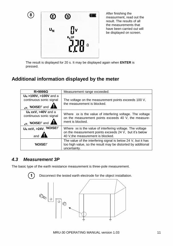
After finishing the measurment, read out the result. The results of all the measurements that have been carried out will be displayed on screen.
The result is displayed for 20 s. It may be displayed again when ENTER is pressed.
Additional information displayed by the meter
R>9999Ω Measurement range exceeded.
UN >100V, >100V and a continuous sonic signal
, ‘NOISE!’ and
The voltage on the measurement points exceeds 100 V, the measurement is blocked.
UN xxV, >40V and a continuous sonic signal
, ‘NOISE!’ and
Where xx is the value of interfering voltage. The voltage on the measurement points exceeds 40 V, the measure-ment is blocked.
UN xxV, >24V, ‘NOISE!’
and
Where xx is the value of interfering voltage. The voltage on the measurement points exceeds 24 V, but it’s below 40 V,the measurement is blocked.
‘NOISE!’ The value of the interfering signal is below 24 V, but it has too high value, so the result may be distorted by additional uncertainty.
4.3 Measurement 3P
The basic type of the earth resistance measurement is three-pole measurement.
Disconnect the tested earth electrode for the object installation.
MRU-30 OPERATING MANUAL version 1.03 12
Use << or >> button to start the meas-
urement of 3P (LED is on). The me-ter is in the mode of noise voltage meas-urement between measurement points.
Press SET/SEL button to select measure-ment voltage.
Use and button to set the meas-
urement voltage value of 25 V or 50 V.
or
Press ENTER to confirm settings or
press ESC to exit without saving the changes.
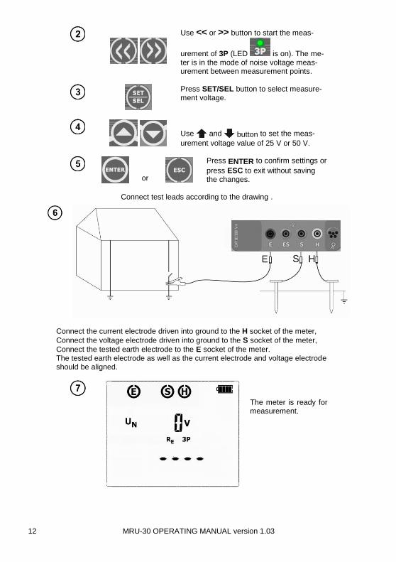
Connect the current electrode driven into ground to the H socket of the meter,
Connect the voltage electrode driven into ground to the S socket of the meter,
Connect the tested earth electrode to the E socket of the meter. The tested earth electrode as well as the current electrode and voltage electrode should be aligned.
The meter is ready for measurement.
Connect test leads according to the drawing .

MRU-30 OPERATING MANUAL version 1.03 13
Press START to commence measure-ment.
Read out the result. The results of all the measurements that have been carried out will be displayed on screen.
Use and button to toggle between the
measurement result components:
RH – resistance of current electrode
RS - resistance of voltage electrode
ER – additional uncertainty caused by the re-sistance of the electrodes
UN – interfering (noise) voltage
The result is displayed for 20s. It may be displayed again when ENTER is pressed.
S
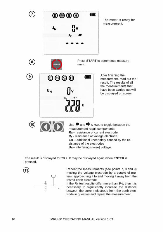
Repeat the measurements (see points 7, 8 and 9) moving the voltage electrode by a couple of me-ters: approaching it to and moving it away from the tested earth electrode. If the RE test results differ more than 3%, then it is necessary to significantly increase the distance between the current electrode from the earth elec-trode in question and repeat the measurement.
Note:
Earth resistance measurement may be carried out if the interference voltage
does not exceed 24 V. The interference voltage is measured up to 100 V, but
over 40 V it is signalled as hazardous.
Do not connect the meter to a voltage exceeding 100 V
- Pay particular attention to the quality of the connection of the tested object with the test leads – the contact area must be cleaned of paint, rust, etc. - If the resistance of the measurement probes is too high, then the measurement of the RE earth electrode will be distorted by additional uncertainty. A particularly high measurement uncertainty is generated if we measure a low value of the earth resistance with probes of a loose contact with the soil (such a situation occurs often if the earth electrode is properly made and the upper layer of the ground is dry and characterized by a low conductivity). Then the relation between the probe re-
MRU-30 OPERATING MANUAL version 1.03 14
sistance and the resistance of the measured earthing is very high, and so is the case of the meas-urement uncertainty which depends on it. What may be done then is to perform, in accordance with the formulae specified in point 12.2, calculations, which will permit to evaluate the influence of the measurement conditions. It is also possible to improve the contact of the probe with the ground, for example by means of moistening of the place when the probe is driven, its driving into the ground in another place or using a 80-centimetre probe. Check also the test leads and make sure the insulation is not damaged and the contacts: test lead – banana plug – probe are not corroded or loosened. In most cases the achieved resolution of the measurement is sufficient, but it is necessary to be con-scious of the uncertainty the measurement is burdened with.
Additional information displayed by the meter
RE>9999Ω Measurement range exceeded.
UN >100V, >100V and a continuous sonic signal ,
‘NOISE!’ or
The voltage on the measurement points exceeds 100 V, the measurement is blocked.
UN xxV, >40V and a continuous sonic
signal , ‘NOISE!’
and
Where xx is the value of interfering voltage. The voltage on the measurement points exceeds 40 V, the measure-ment is blocked.
UN xxV, >24V,
‘NOISE!’ and
Where xx is the value of interfering voltage. The voltage on the measurement points exceeds 24 V, but it’s below 40 V,the measurement is blocked.
‘NOISE!’ The value of the interfering signal is below 24 V, but it has too high value, so the result may be distorted by additional uncertainty.
and ER along with % value
The uncertainty caused by resistance of the electrodes > 30%. (Uncertainties calculated on the basis of the meas-ured values.)
and RH or RS along with Ω value
The resistance of H and S electrodes, or one of them ex-ceeds 19,9 kΩ, the proper measurement is not possible.
Flashing symbols:
, ,
Flashing symbols E or H or S, or both of them, or all three at the same time – one or two or three test leads are dis-connected from the measurement sockets.
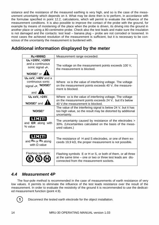
4.4 Measurement 4P
The four-pole method is recommended in the case of measurements of earth resistance of very low values. It permits to eliminate the influence of the test leads resistance over the result of the measurement. In order to evaluate the resistivity of the ground it is recommended to use the dedicat-ed measurement function (point 4.9).
Disconnect the tested earth electrode for the object installation.

MRU-30 OPERATING MANUAL version 1.03 15
Use << or >> button to start the meas-
urement of 4P (LED is on). The me-ter is in the mode of noise voltage meas-urement between measurement points).
Press SET/SEL button to select measure-ment voltage.
Use and button to set the meas-
urement voltage value of 25 V or 50 V
or
Press ENTER to confirm settings or
press ESC to exit without saving the changes.
Connect the current electrode driven into ground to the H socket of the meter.
Connect the voltage electrode driven into ground to the S socket of the meter.
Connect the tested earth electrode to the E socket of the meter.
Connect the ES socket to the earth electrode In question below the E cable. The tested earth electrode as well as the current electrode and voltage elec-trode should be aligned.
Connect test leads according to the drawing.
MRU-30 OPERATING MANUAL version 1.03 16
The meter is ready for measurement.
Press START to commence measure-ment.
After finishing the measurment, read out the result. The results of all the measurements that have been carried out will be displayed on screen.
Use and button to toggle between the
measurement result components:
RH – resistance of current electrode
RS - resistance of voltage electrode
ER – additional uncertainty caused by the re-sistance of the electrodes
UN – interfering (noise) voltage.
The result is displayed for 20 s. It may be displayed again when ENTER is pressed.
S
Repeat the measurements (see points 7, 8 and 9) moving the voltage electrode by a couple of me-ters: approaching it to and moving it away from the tested earth electrode. If the RE test results differ more than 3%, then it is necessary to significantly increase the distance between the current electrode from the earth elec-trode in question and repeat the measurement.

MRU-30 OPERATING MANUAL version 1.03 17
Note:
Earth resistance measurement may be carried out if the interference voltage
does not exceed 24 V. The interference voltage is measured up to 100 V, but
over 40 V it is signalled as hazardous.
Do not connect the meter to a voltage exceeding 100 V.
- Pay particular attention to the quality of the connection of the tested object with the test leads – the contact area must be cleaned of paint, rust, etc. - If the resistance of the measurement probes is too high, then the measurement of the RE earth electrode will be distorted by additional uncertainty. A particularly high measurement uncertainty is generated if we measure a low value of the earth resistance with probes of a loose contact with the soil (such a situation occurs often if the earth electrode is properly made and the upper layer of the ground is dry and characterized by a low conductivity). Then the relation between the probe re-sistance and the resistance of the measured earthing is very high, and so is the case of the meas-urement uncertainty which depends on it. What may be done then is to perform, in accordance with the formulae specified in point 12.2, calculations, which will permit to evaluate the influence of the measurement conditions. It is also possible to improve the contact of the probe with the ground, for example by means of moistening of the place when the probe is driven, its driving into the ground in another place or using a 80-centimetre probe. Check also the test leads and make sure the insulation is not damaged and the contacts: test lead – banana plug – probe are not corroded or loosened. In most cases the achieved resolution of the measurement is sufficient, but it is necessary to be con-scious of the uncertainty the measurement is burdened with.
Additional information displayed by the meter
RE>9999Ω Measurement range exceeded.
UN >100V, >100V and a continuous sonic signal ,
‘NOISE!’ and
The voltage on the measurement points exceeds 100 V, the measurement is blocked.
UN xxV, >40V and a continuous sonic
signal , ‘NOISE!’
and
Where xx is the value of interfering voltage. The voltage on the measurement points exceeds 40 V, the measure-ment is blocked.
UN xxV, >24V,
‘NOISE!’ and
Where xx is the value of interfering voltage. The voltage on the measurement points exceeds 24 V, but it’s below 40V, the measurement is blocked.
‘NOISE!’ The value of the interfering signal is below 24 V, but it has too high value, so the result may be distorted by additional uncertainty.
and ER along with % value
The uncertainty caused by resistance of the electrodes > 30%. (Uncertainties calculated on the basis of the meas-ured values.)
and RH or RS along with Ω value
The resistance of H and S electrodes, or one of them ex-ceeds 19,9 kΩ, the proper measurement is not possible.

MRU-30 OPERATING MANUAL version 1.03 18
Flashing symbols:
, , ,
Flashing symbols E or H or S, or both of them, or all three at the same time, one or two or three test leads are dis-connected from the measurement sockets.
4.5 Measurement 3P + clamp
Use << or >> button to start the meas-
urement of 3P+ (LED is on). The meter is in the mode of noise voltage measurement between measurement points and also it measures the current flowing through the clamp.
Press SET/SEL button to select measure-ment voltage.
Use and button to set the meas-
urement voltage value of 25 V or 50 V.
or
Press ENTER to confirm settings or
press ESC to exit without saving the changes.
Connect the current electrode driven into ground to the H socket of the meter,
Connect the voltage electrode driven into ground to the S socket of the meter,
Connect the tested earth electrode to the E socket of the meter, The tested earth electrode as well as the current electrode and voltage electrode should be aligned.
Attach the clamp around the tested earth electrode below the E cable connec-tion.
Connect test leads according to the drawing.
MRU-30 OPERATING MANUAL version 1.03 19
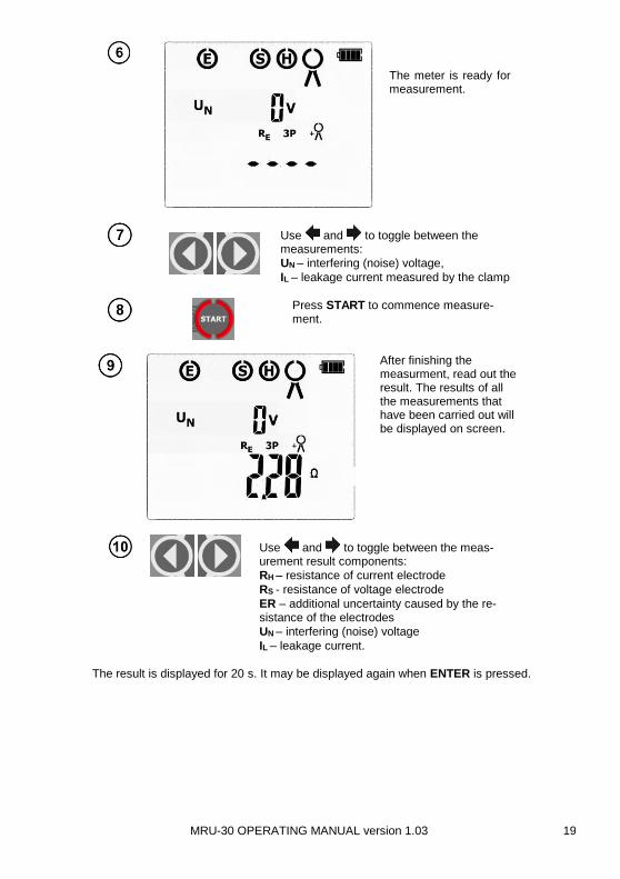
The meter is ready for measurement.
Use and to toggle between the measurements:
UN – interfering (noise) voltage,
IL – leakage current measured by the clamp
Press START to commence measure-ment.
After finishing the measurment, read out the result. The results of all the measurements that have been carried out will be displayed on screen.
Use and to toggle between the meas-urement result components:
RH – resistance of current electrode
RS - resistance of voltage electrode
ER – additional uncertainty caused by the re-sistance of the electrodes
UN – interfering (noise) voltage
IL – leakage current.
The result is displayed for 20 s. It may be displayed again when ENTER is pressed.

MRU-30 OPERATING MANUAL version 1.03 20
S
Repeat the measurements (see points 6, 8 and 9) moving the voltage electrode by a couple of me-ters: approaching it to and moving it away from the tested earth electrode. If the RE test results differ more than 3%, then it is necessary to significantly increase the distance between the current electrode from the earth elec-trode in question and repeat the measurement.
Note:
Earth resistance measurement may be carried out if the interference voltage
does not exceed 24 V. The interference voltage is measured up to 100 V, but
over 40 V it is signalled as hazardous.
Do not connect the meter to a voltage exceeding 100 V.
- The clamps are not the part of the meter’s standard accessories, they are to be purchased sepa-rately. - The clamp must be calibrated before it is used for the first time. It may be periodically calibrated in order to avoid the influence of the ageing elements upon the resolution of measurements. The clamp calibration option is described in point 4.7. - Pay particular attention to the quality of the connection of the tested object with the test leads – the contact area must be cleaned of paint, rust, etc. - If the resistance of the measurement probes is too high, then the measurement of the RE earth elec-trode will be distorted by additional uncertainty. A particularly high measurement uncertainty is gen-erated if we measure a low value of the earth resistance with probes of a loose contact with the soil (such a situation occurs often if the earth electrode is properly made and the upper layer of the ground is dry and characterized by a low conductivity). Then the relation between the probe re-sistance and the resistance of the measured earthing is very high, and so is the case of the meas-urement uncertainty which depends on it. What may be done then is to perform, in accordance with the formulae specified in point 12.2, calculations, which will permit to evaluate the influence of the measurement conditions. It is also possible to improve the contact of the probe with the ground, for example by means of moistening of the place when the probe is driven, its driving into the ground in another place or using a 80-centimetre probe. Check also the test leads and make sure the insulation is not damaged and the contacts: test lead – banana plug – probe are not corroded or loosened. In most cases the achieved resolution of the measurement is sufficient, but it is necessary to be con-scious of the uncertainty the measurement is burdened with.
Additional information displayed by the meter
RE>9999Ω Measurement range exceeded.
UN >100V, >100V and a continuous sonic signal ,
‘NOISE!’ and
The voltage on the measurement points exceeds 100 V, the measurement is blocked.
UN xxV, >40V and a continuous sonic
signal , ‘NOISE!’
and
Where xx is the value of interfering voltage. The voltage on the measurement points exceeds 40 V, the measure-ment is blocked.

MRU-30 OPERATING MANUAL version 1.03 21
UN xxV, >24V,
‘NOISE!’ and
Where xx is the value of interfering voltage. The voltage on the measurement points exceeds 24 V, but it’s below 40 V, the measurement is blocked.
‘NOISE!’ The value of the interfering signal is below 24 V, but it has too high value, so the result may be distorted by additional uncertainty.
and ER along with % value
The uncertainty caused by resistance of the electrodes > 30%. (Uncertainties calculated on the basis of the meas-ured values.)
and RH or RS along with Ω value
The resistance of H and S electrodes, or one of them ex-ceeds 19,9 kΩ, the proper measurement is not possible.
Flashing symbols:
, ,
Flashing symbols E or H or S, or both of them, or all three at the same time – one or two or three test leads are dis-connected from the measurement sockets.
Flashing clamp
symbol
Current clamp disconnected or the current value meas-ured by the clamp is too low.
IL xxA , I>1A, Interfering current exceeds 3A – the measurement is not possible.
4.6 Two-clamp measurement
Two-clamp measurement is applied where there is no possibility of using earth electrodes (rods).
NOTE! The two-clamp method may be used solely in the case of multiple earthing
systems.
Use << or >> button to start the meas-
urement of (LED is on). The me-ter is in the mode of noise voltage meas-urement between measurement points and also it measures the current flowing through the receiving clamp.
Connect test leads according to the drawing.

MRU-30 OPERATING MANUAL version 1.03 22
Connect the transmission clamp to sockets H and E, while the measurements
clamp should be connected to the clamp socket . Attach the transmission clamp and the measurement clamp around the tested earth electrode at least 30cm from each other.
The meter is ready for measurement.
Press START to commence measure-ment.
Upon completing the measurement read out the result and the value of the leakage current.
The result is displayed for 20 s. It may be displayed again when ENTER is pressed.
MRU-30 OPERATING MANUAL version 1.03 23
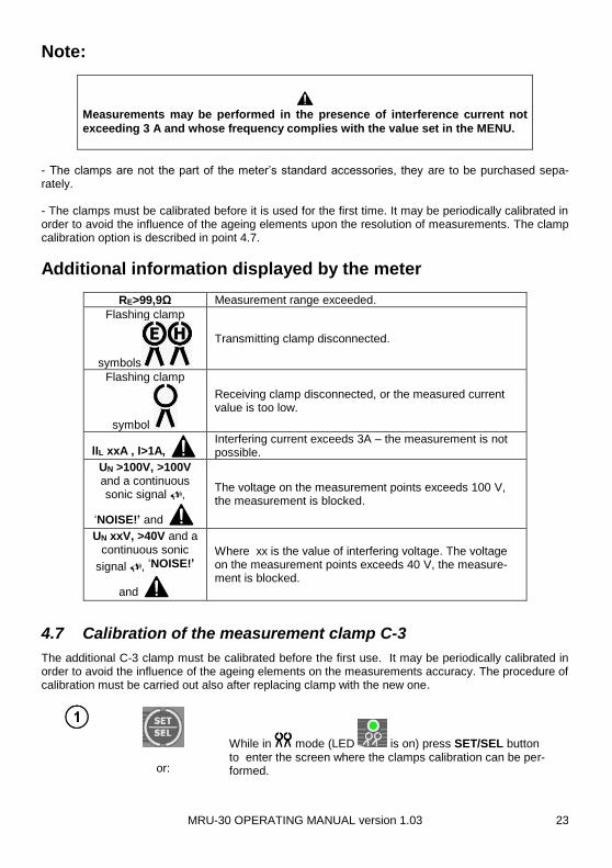
Note:
Measurements may be performed in the presence of interference current not
exceeding 3 A and whose frequency complies with the value set in the MENU.
- The clamps are not the part of the meter’s standard accessories, they are to be purchased sepa-rately. - The clamps must be calibrated before it is used for the first time. It may be periodically calibrated in order to avoid the influence of the ageing elements upon the resolution of measurements. The clamp calibration option is described in point 4.7.
Additional information displayed by the meter
RE>99,9Ω Measurement range exceeded.
Flashing clamp
symbols
Transmitting clamp disconnected.
Flashing clamp
symbol
Receiving clamp disconnected, or the measured current value is too low.
lIL xxA , I>1A, Interfering current exceeds 3A – the measurement is not possible.
UN >100V, >100V and a continuous sonic signal ,
‘NOISE!’ and
The voltage on the measurement points exceeds 100 V, the measurement is blocked.
UN xxV, >40V and a continuous sonic
signal , ‘NOISE!’
and
Where xx is the value of interfering voltage. The voltage on the measurement points exceeds 40 V, the measure-ment is blocked.
4.7 Calibration of the measurement clamp C-3
The additional C-3 clamp must be calibrated before the first use. It may be periodically calibrated in order to avoid the influence of the ageing elements on the measurements accuracy. The procedure of calibration must be carried out also after replacing clamp with the new one.
or:
While in mode (LED is on) press SET/SEL button to enter the screen where the clamps calibration can be per-formed.
MRU-30 OPERATING MANUAL version 1.03 24
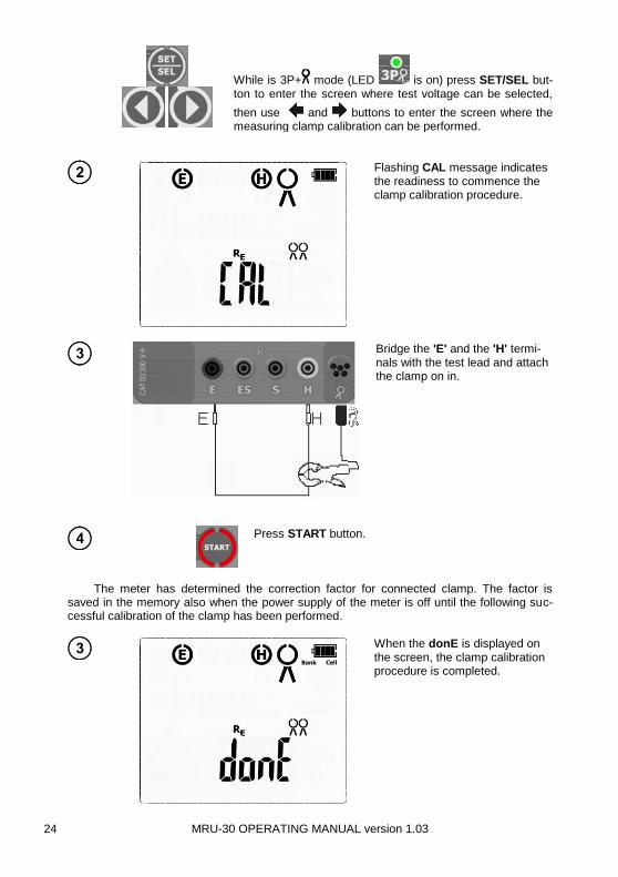
While is 3P+ mode (LED is on) press SET/SEL but-ton to enter the screen where test voltage can be selected,
then use and buttons to enter the screen where the measuring clamp calibration can be performed.
Flashing CAL message indicates the readiness to commence the clamp calibration procedure.
Bridge the 'E' and the 'H' termi-nals with the test lead and attach the clamp on in.
Press START button.
The meter has determined the correction factor for connected clamp. The factor is
saved in the memory also when the power supply of the meter is off until the following suc-cessful calibration of the clamp has been performed.
When the donE is displayed on the screen, the clamp calibration procedure is completed.
MRU-30 OPERATING MANUAL version 1.03 25
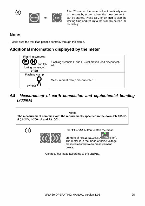
or
After 20 second the meter will automatically return to the standby screen where the measurement
can be started. Press ESC or ENTER to skip the waiting time and return to the standby screen im-mediately.
Note: - Make sure the test lead passes centrally through the clamp.
Additional information displayed by the meter
Flashing symbols:
and fol-lowing message:
oPEn
Flashing symbols E and H – calibration lead disconnect-ed.
Flashing clamp
symbol
Measurement clamp disconnected.
4.8 Measurement of earth connection and equipotential bonding
(200mA)
Note:
The measurement complies with the requirements specified in the norm EN 61557-
4 (U<24V, I>200mA and R≤10Ω).
Use << or >> button to start the meas-
urement of RCONT 200mA (LED is on). The meter is in the mode of noise voltage measurement between measurement points.
Connect test leads according to the drawing.

MRU-30 OPERATING MANUAL version 1.03 26
The meter is ready for measurement.
Press START to commence measurement.
Upon completing the measurement read out the result and the value of the interfering voltage.
The result is displayed for 20 s. It may be displayed again when ENTER is pressed.
Additional information displayed by the meter
R>1999Ω Measurement range exceeded.
UN >100V, >100V and a continuous sonic signal
, ‘NOISE!’ and
The voltage on the measurement points exceeds 100 V, the measurement is blocked.
MRU-30 OPERATING MANUAL version 1.03 27
UN xxV, >40V and a continuous sonic signal
, ‘NOISE!’ and
Where xx is the value of interfering voltage. The voltage on the measurement points exceeds 40 V, the measure-ment is blocked.
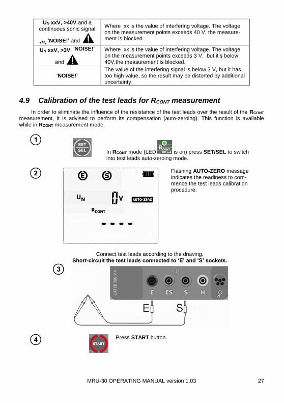
UN xxV, >3V, ‘NOISE!’
and
Where xx is the value of interfering voltage. The voltage on the measurement points exceeds 3 V, but it’s below 40V,the measurement is blocked.
‘NOISE!’ The value of the interfering signal is below 3 V, but it has too high value, so the result may be distorted by additional uncertainty.
4.9 Calibration of the test leads for RCONT measurement
In order to eliminate the influence of the resistance of the test leads over the result of the RCONT measurement, it is advised to perform its compensation (auto-zeroing). This function is available
while in RCONT measurement mode.
In RCONT mode (LED is on) press SET/SEL to switch into test leads auto-zeroing mode.
Flashing AUTO-ZERO message indicates the readiness to com-mence the test leads calibration procedure.
Press START button.
Connect test leads according to the drawing.
Short-circuit the test leads connected to ‘E’ and ‘S’ sockets.

MRU-30 OPERATING MANUAL version 1.03 28
When AUTO-ZERO is displayed on the screen, the test leads cali-bration procedure is completed. The result is compensated value, and the correction is available for
RCONT. The compensation is also active after switching the meter off and on (it is indicated by the
AUTO-ZERO being displayed on screen).
In order to delete compensation (restore default calibration) proceed with the above steps with open (not shorted) test leads. In the place where the result is
expected oFF message will appear (test leads compensation is now deactivated
). When the procedure is completed AUTO-ZERO message will disappear from the screen.
or
After 20 seconds the meter will automatically re-turn to the standby screen where the measure-
ment can be started. Press ESC or ENTER to skip the waiting time and return to the standby screen immediately.
4.10 Earth resistivity measurement
For the purpose of earth resistivity measurements – which are used as a preliminary measure for the project of earthing systems or in geology - there is a separate function: earth resistivity measure-
ments . The function is metrologically identical as the four-pole earth resistance measurement, but it includes an additional procedure of storing of the distance between the electrodes. The result of the measurement is the resistance value which is calculated automatically in accordance with the follow-
ing formula: ρ = 2LRE, which is used in the Wenner’s measurement method. The method in question assumes equal distances between electrodes.
Use << or >> buttons to switch into earth
resistivity measurement mode (LED is on). The meter is in the mode of noise voltage measurement between measure-ment points and also it measures the cur-rent flowing through the receiving clamp.
Press SET/SEL button to switch into mode of selecting the distance between the elec-trodes.
Use and to set the distance be-
tween the electrodes. From 1 to 50 m, with
1 m step, or from 1 to 150 ft, with 1 ft step.
MRU-30 OPERATING MANUAL version 1.03 29
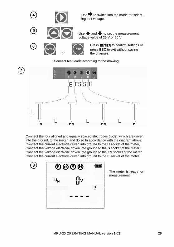
Use to switch into the mode for select-ing test voltage.
Use and to set the measurement
voltage value of 25 V or 50 V
or
Press ENTER to confirm settings or
press ESC to exit without saving the changes.
Connect test leads according to the drawing.
Connect the four aligned and equally spaced electrodes (rods), which are driven into the ground, to the meter, and do so In accordance with the diagram above:
Connect the current electrode driven into ground to the H socket of the meter,
Connect the voltage electrode driven into ground to the S socket of the meter,
Connect the voltage electrode driven into ground to the ES socket of the meter,
Connect the current electrode driven into ground to the E socket of the meter.
The meter is ready for measurement.

MRU-30 OPERATING MANUAL version 1.03 30
Press START to commence measurement.
After finishing the measurment, read out the result. The results of all the measurements that have been carried out will be displayed on screen.
Use and to toggle between the meas-urement result components:
RH – resistance of current electrode
RS - resistance of voltage electrode
ER – additional uncertainty caused by the re-sistance of the electrodes
UN – interfering (noise) voltage .
The result is displayed for 20 s. It may be displayed again when ENTER is pressed.
Note:
Earth resistivity measurement may be performed if the interference voltage
does not exceed 24V. The interference voltage is measured up to 100 V, but
over 40V is it signalled as hazardous.
Do not connect the meter to a voltage exceeding 100 V
- Calculations are based upon the assumption that the distances between the specific measurement electrodes are equal (the Wenner’s method). If this is not the case the earthing resistance measure-ment must be carried out by means of the four-pole method and calculations must be performed indi-vidually. - Pay particular attention to the quality of the connection of the tested object with the test leads – the contact area must be cleaned of paint, rust, etc. - If the resistance of the measurement probes is too high, then the measurement of the RE earth elec-trode will be distorted by additional uncertainty. A particularly high measurement uncertainty is gen-erated if we measure a low value of the earth resistance with probes of a loose contact with the soil (such a situation occurs often if the earth electrode is properly made and the upper layer of the ground is dry and characterized by a low conductivity). Then the relation between the probe re-

MRU-30 OPERATING MANUAL version 1.03 31
sistance and the resistance of the measured earthing is very high, and so is the case of the meas-urement uncertainty which depends on it. What may be done then is to perform, in accordance with the formulae specified in point 12.2, calculations, which will permit to evaluate the influence of the measurement conditions. It is also possible to improve the contact of the probe with the ground, for example by means of moistening of the place when the probe is driven, its driving into the ground in another place or using a 80 cm probe (rod). Check also the test leads and make sure the insulation is not damaged and the contacts: test lead – banana plug – probe are not corroded or loosened. In most cases the achieved resolution of the measurement is sufficient, but it is necessary to be con-scious of the uncertainty the measurement is burdened with.
Additional information displayed by the meter
>xxxkΩm or
>xxxkΩft
Measurement range exceeded, where xxx is maximum value that can be measured for the selected settings.
UN >100V, >100V and a continuous sonic signal ,
‘NOISE!’ and
The voltage on the measurement points exceeds 100 V, the measurement is blocked.
UN xxV, >40V and a continuous sonic
signal , ‘NOISE!’
and
Where xx is the value of interfering voltage. The voltage on the measurement points exceeds 40 V, the measure-ment is blocked.
UN xxV, >24V,
‘NOISE!’ and
Where xx is the value of interfering voltage. The voltage on the measurement points exceeds 24 V, but it’s below 40 V, the measurement is blocked.
‘NOISE!’ The value of the interfering signal is below 24 V, but it has too high value, so the result may be distorted by additional uncertainty.
and ER along with % value
The uncertainty caused by resistance of the electrodes > 30%. (Uncertainties calculated on the basis of the meas-ured values.)
and RH or RS along with Ω value
The resistance of H and S electrodes, or one of them ex-ceeds 19,9 kΩ, the proper measurement is not possible.
Flashing symbols:
, , ,
Flashing symbols E or ES or H or S, or two of them, or three, or all of them at the same time – one or two or three or four test leads are disconnected from the measure-ment sockets.
MRU-30 OPERATING MANUAL version 1.03 32
5 Memory of measurement results
The MRU-30 meter has memory divided into 10 banks of 99 cells each. Thanks to dynamic memory allocation, each of the memory cells can contain different quantity of single measurement results, depending on the needs. Optimal use of the memory can be ensured in this way. Each measurement result can be stored in a memory cell marked with a selected number and in a selected memory bank. Thanks to this, the user of the meter can, at his/her option, assign memory cell num-bers to individual measurement points and the memory bank numbers to individual facilities. The user may also perform measurements in any chosen sequence and repeat them without losing other data.
Memory of measurement results is not deleted when the meter is switched off. Thanks to this, the data can be later read or sent to a computer. The number of a current memory cell or memory bank is not changed either.
Note: Results of single measurement can be stored in one memory cell. - After entering the measurement result, the ID number of the cell is automatically increased. - It is recommended to delete the memory after reading the data or before performing a new series of measurements that may be stored into the same memory cells as the previous ones.
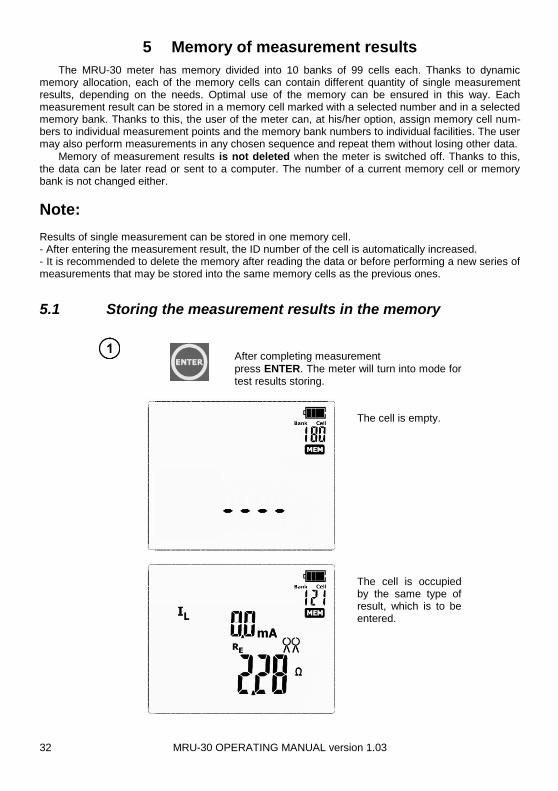
5.1 Storing the measurement results in the memory
After completing measurement
press ENTER. The meter will turn into mode for test results storing.
The cell is empty.
The cell is occupied by the same type of result, which is to be entered.

MRU-30 OPERATING MANUAL version 1.03 33
Use and buttons to preview the results stored in the selected cell. If any.
To change the cell number or bank number:
When the cell number is flashing, use and
buttons to set the desired number of the
cell.
Press SET/SEL button – bank number is flash-ing.
Use and buttons to set the desired
number of the bank.
After selecting the desired bank and cell, press
ENTER button, to save the result in the memory. Re-cording is indicated by a triple beep sound.
Press ESC to return to the measurement screen without saving.
If you try to store data in an occupied memory cell, the following
warning message will appear: OVEr ?:
or
Press ENTER, to overwrite the re-
sult or ESC, to cancel and select other cell or bank.
Note: - After the measurement, its result is shown on the display for 20 s or until:
the measurement function is changed,
Auto-OFF function is activated,
the meter detects interference voltage> 40 V,
one of the following operations is performed:

MRU-30 OPERATING MANUAL version 1.03 34
o ESC button is pressed to exit to the voltmeter, o next measurement is performed, o an entry into the memory is introduced.
- After exiting to the voltmeter by pressing ESC, or after 20 s have gone by or after the test results
have been stored into the memory, the last result may be recalled by pressing ENTER.
- Complete set of results (main result and supplementary results) for a given measuring func-
tion and preset measurement settings are stored in the memory.
5.2 Viewing memory data
Use << or >> to browse the memory: MEM
(LED is on).
Use and buttons to preview the test results components stored in the selected
cell, if any exist.
To change the cell number or bank number:
When the cell number is flashing, use and
buttons to set the desired number of the
cell.
Press SET/SEL button – bank number is flashing.
Use and buttons to set the desired
number of the bank.
- Viewing test results components is disabled for RCONT and 2P measurements.
5.3 Deleting memory data
You can delete the entire memory or its individual cells or banks.
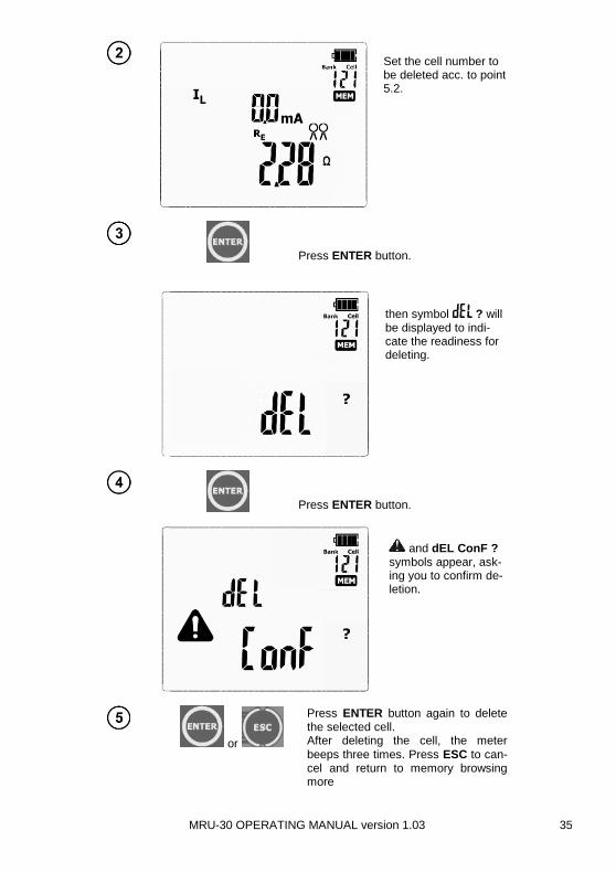
5.3.1 Deleting cell data
Use << or >> to browse the memory:
MEM (LED is on).
MRU-30 OPERATING MANUAL version 1.03 35
Set the cell number to be deleted acc. to point 5.2.
Press ENTER button.
then symbol ? will be displayed to indi-cate the readiness for deleting.
Press ENTER button.
and dEL ConF ? symbols appear, ask-ing you to confirm de-letion.
or
Press ENTER button again to delete the selected cell. After deleting the cell, the meter
beeps three times. Press ESC to can-cel and return to memory browsing more
MRU-30 OPERATING MANUAL version 1.03 36
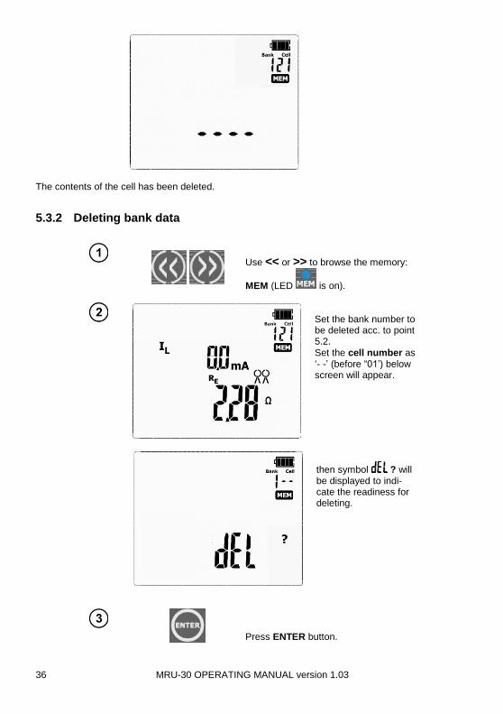
The contents of the cell has been deleted.
5.3.2 Deleting bank data
Use << or >> to browse the memory:
MEM (LED is on).
Set the bank number to be deleted acc. to point 5.2.
Set the cell number as ‘- -’ (before “01’) below screen will appear.
then symbol ? will be displayed to indi-cate the readiness for deleting.
Press ENTER button.
MRU-30 OPERATING MANUAL version 1.03 37
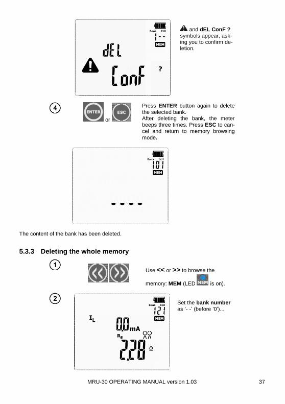
and dEL ConF ? symbols appear, ask-ing you to confirm de-letion.
or
Press ENTER button again to delete the selected bank. After deleting the bank, the meter
beeps three times. Press ESC to can-cel and return to memory browsing
mode.
The content of the bank has been deleted.
5.3.3 Deleting the whole memory
Use << or >> to browse the
memory: MEM (LED is on).
Set the bank number as ‘- -’ (before ‘0’)...
MRU-30 OPERATING MANUAL version 1.03 38
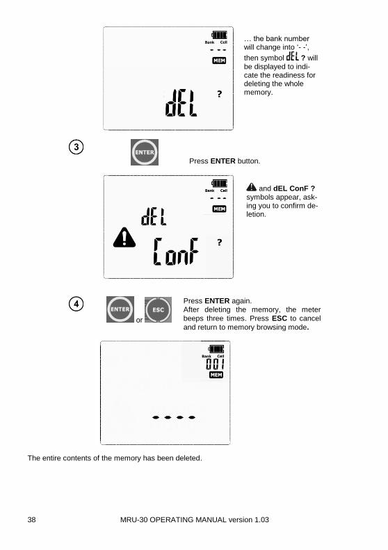
… the bank number will change into ‘- -’,
then symbol ? will be displayed to indi-cate the readiness for deleting the whole memory.
Press ENTER button.
and dEL ConF ? symbols appear, ask-ing you to confirm de-letion.
or
Press ENTER again. After deleting the memory, the meter
beeps three times. Press ESC to cancel
and return to memory browsing mode.
The entire contents of the memory has been deleted.
MRU-30 OPERATING MANUAL version 1.03 39
6 Data transmission
6.1 Computer connection accessories
What is necessary in order to operate the meter with a computer is additional accessories, name-ly a USB cable and appropriate software. If the required accessories have not been purchased along with the meter, then they are available from the manufacturer or an authorized distributor. The accessories may be used with other devices manufactured by SONEL S.A. which are equipped with the USB interface, or other (depending on the device). Detailed information regarding software is available from the manufacturer or an authorized dis-tributor.
6.2 Data transmission through USB port
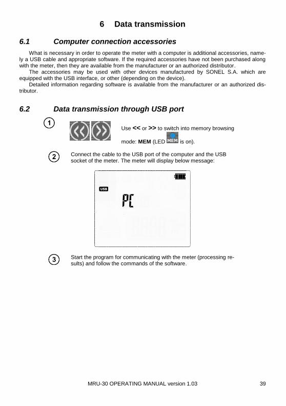
Use << or >> to switch into memory browsing
mode: MEM (LED is on).
Connect the cable to the USB port of the computer and the USB socket of the meter. The meter will display below message:
Start the program for communicating with the meter (processing re-sults) and follow the commands of the software.
MRU-30 OPERATING MANUAL version 1.03 40
7 Firmware update
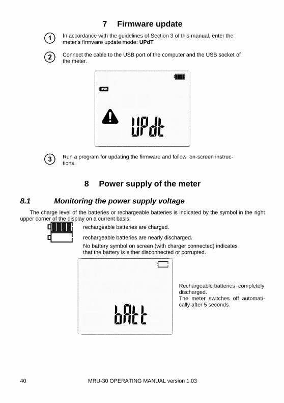
In accordance with the guidelines of Section 3 of this manual, enter the
meter’s firmware update mode: UPdT
Connect the cable to the USB port of the computer and the USB socket of the meter.
Run a program for updating the firmware and follow on-screen instruc-tions.
8 Power supply of the meter
8.1 Monitoring the power supply voltage
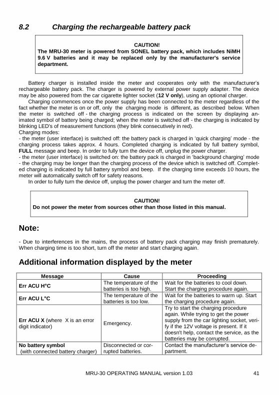
The charge level of the batteries or rechargeable batteries is indicated by the symbol in the right upper corner of the display on a current basis:
rechargeable batteries are charged.
rechargeable batteries are nearly discharged.
No battery symbol on screen (with charger connected) indicates that the battery is either disconnected or corrupted.
Rechargeable batteries completely discharged. The meter switches off automati-cally after 5 seconds.
MRU-30 OPERATING MANUAL version 1.03 41
8.2 Charging the rechargeable battery pack
CAUTION!
The MRU-30 meter is powered from SONEL battery pack, which includes NiMH
9.6 V batteries and it may be replaced only by the manufacturer's service
department.
Battery charger is installed inside the meter and cooperates only with the manufacturer’s
rechargeable battery pack. The charger is powered by external power supply adapter. The device
may be also powered from the car cigarette lighter socket (12 V only), using an optional charger. Charging commences once the power supply has been connected to the meter regardless of the fact whether the meter is on or off, only the charging mode is different, as described below. When the meter is switched off - the charging process is indicated on the screen by displaying an-imated symbol of battery being charged; when the meter is switched off - the charging is indicated by blinking LED's of measurement functions (they blink consecutively in red). Charging modes: - the meter (user interface) is switched off: the battery pack is charged in ‘quick charging’ mode - the charging process takes approx. 4 hours. Completed charging is indicated by full battery symbol,
FULL message and beep. In order to fully turn the device off, unplug the power charger. - the meter (user interface) is switched on: the battery pack is charged in ‘background charging’ mode - the charging may be longer than the charging process of the device which is switched off. Complet-ed charging is indicated by full battery symbol and beep. If the charging time exceeds 10 hours, the meter will automatically switch off for safety reasons. In order to fully turn the device off, unplug the power charger and turn the meter off.
CAUTION!
Do not power the meter from sources other than those listed in this manual.
Note: - Due to interferences in the mains, the process of battery pack charging may finish prematurely. When charging time is too short, turn off the meter and start charging again.
Additional information displayed by the meter
Message Cause Proceeding
Err ACU H°C The temperature of the batteries is too high.
Wait for the batteries to cool down. Start the charging procedure again.
Err ACU L°C The temperature of the batteries is too low.
Wait for the batteries to warm up. Start the charging procedure again.
Err ACU X (where X is an error digit indicator)
Emergency.
Try to start the charging procedure again. While trying to get the power supply from the car lighting socket, veri-fy if the 12V voltage is present. If it doesn't help, contact the service, as the batteries may be corrupted.
No battery symbol (with connected battery charger)
Disconnected or cor-rupted batteries.
Contact the manufacturer’s service de-partment.

MRU-30 OPERATING MANUAL version 1.03 42
8.3 General principles of using Ni-MH batteries
- Store the accumulators in a dry, cool and well ventilated place and protect them from direct sunlight.
The temperature of the environment in the case of prolonged storage should not exceed 30C. If the accumulators are stored for a long time in a high temperature, then the occurring chemical processes may reduce their lifetime. - Ni-MH batteries normally withstand 500-1000 charging cycles. The accumulators reach their maxi-mum capacity after being formatted (2-3 charge and discharge cycles). The most important factor which influences the lifetime of the battery is the depth of discharge. The deeper the discharge of the battery, the shorter its lifetime. - The memory effect is limited in the case of Ni-MH batteries. These batteries may be charged at any point with no serious consequences. However, it is recommended to discharge them completely eve-ry few cycles. - During storage of Ni-MH batteries they are discharged at the rate of approximately 20% per month. Keeping them at high temperatures may accelerate this process even 100%. In order to prevent ex-cessive discharge of batteries, after which it would be necessary to format them, it is recommended to charge the batteries from time to time (even if not in use). - Modern fast chargers detect both too low and too high a temperature of batteries and react to the situation adequately. Too low a temperature should prevent the start of the process of charging, which might damage the battery irreparably. An increase of the temperature of the battery is a signal to stop charging and is a typical phenomenon. However charging at a high temperature of the envi-ronment apart from reducing the lifetime causes an accelerated increase of the temperature of the battery, which will be not charged to its full capacity. - Remember that in the case of quick charging batteries are charged to approximately 80% of their capacity; better results may be obtained if the process of charging is continued: the charger goes then to the phase of charging with a low current and after next couple of hours the batteries are charged to their full capacity. - Do not charge or use batteries in extreme temperatures. Extreme temperatures reduce the lifetime of batteries. Avoid placing devices powered from batteries in very hot environments. The nominal working temperature must be absolutely observed.

MRU-30 OPERATING MANUAL version 1.03 43
9 Cleaning and maintenance
NOTE!
Apply solely the maintenance methods specified by the manufacturer within the present
manual.
The casing of the meter may be cleaned with a soft, damp cloth using all-purpose detergents. Do not use any solvents or cleaning agents which might scratch the casing (powders, pastes, etc.). Clean the probe with water and dry it. Before the probe is stored for a prolonged period of time it is recommended to grease it with any machine lubricant. The reels and test leads should be cleaned with water and detergents, and then dried. The electronic system of the meter does not require maintenance.
10 Storage
In the case of storage of the device, the following recommendations must be observed:
Disconnect all the test leads from the meter,
Clean the meter and all its accessories thoroughly,
Wind the long test leads onto the reels,
In order to prevent a total discharge of the accumulators in the case of a prolonged storage, charge them from time to time.
11 Dismantling and disposal
Worn-out electric and electronic equipment should be gathered selectively, i.e. it must not be placed with waste of another kind.
Worn-out electronic equipment should be sent to a collection point in accordance with the law of worn-out electric and electronic equipment.
Before the equipment is sent to a collection point, do not dismantle any elements. Observe the local regulations concerning disposal of packages, worn-out batteries and accumulators.
MRU-30 OPERATING MANUAL version 1.03 44
12 Technical specifications
The specified accuracy applies to meter terminals.
The abbreviation ‘m.v.’ in the basic uncertainty definition means the measured value.
12.1 Basic data
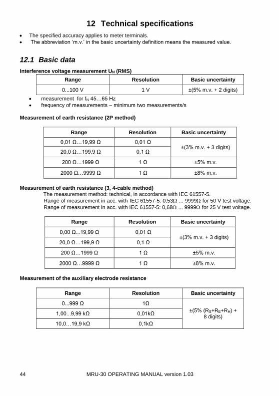
Interference voltage measurement UN (RMS)
Range Resolution Basic uncertainty
0...100 V 1 V ±(5% m.v. + 2 digits)
measurement for fN 45…65 Hz
frequency of measurements – minimum two measurements/s
Measurement of earth resistance (2P method)
Range Resolution Basic uncertainty
0,01 Ω…19,99 Ω 0,01 Ω ±(3% m.v. + 3 digits)
20,0 Ω…199,9 Ω 0,1 Ω
200 Ω…1999 Ω 1 Ω ±5% m.v.
2000 Ω…9999 Ω 1 Ω ±8% m.v.
Measurement of earth resistance (3, 4-cable method) The measurement method: technical, in accordance with IEC 61557-5.
Range of measurement in acc. with IEC 61557-5: 0,53 ... 9999 for 50 V test voltage.
Range of measurement in acc. with IEC 61557-5: 0,68 ... 9999 for 25 V test voltage.
Range Resolution Basic uncertainty
0,00 Ω...19,99 Ω 0,01 Ω ±(3% m.v. + 3 digits)
20,0 Ω…199,9 Ω 0,1 Ω
200 Ω…1999 Ω 1 Ω ±5% m.v.
2000 Ω…9999 Ω 1 Ω ±8% m.v.
Measurement of the auxiliary electrode resistance
Range Resolution Basic uncertainty
0...999 Ω 1Ω
±(5% (RS+RE+RH) + 8 digits)
1,00...9,99 kΩ 0,01kΩ
10,0…19,9 kΩ 0,1kΩ
MRU-30 OPERATING MANUAL version 1.03 45
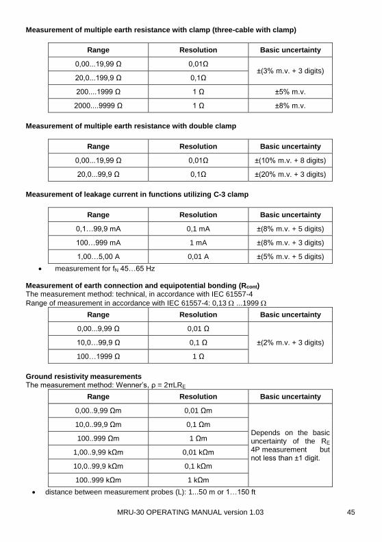
Measurement of multiple earth resistance with clamp (three-cable with clamp)
Range Resolution Basic uncertainty
0,00...19,99 Ω 0,01Ω ±(3% m.v. + 3 digits)
20,0...199,9 Ω 0,1Ω
200....1999 Ω 1 Ω ±5% m.v.
2000....9999 Ω 1 Ω ±8% m.v.
Measurement of multiple earth resistance with double clamp
Range Resolution Basic uncertainty
0,00...19,99 Ω 0,01Ω ±(10% m.v. + 8 digits)
20,0...99,9 Ω 0,1Ω ±(20% m.v. + 3 digits)
Measurement of leakage current in functions utilizing C-3 clamp
Range Resolution Basic uncertainty
0,1…99,9 mA 0,1 mA ±(8% m.v. + 5 digits)
100…999 mA 1 mA ±(8% m.v. + 3 digits)
1,00…5,00 A 0,01 A ±(5% m.v. + 5 digits)
measurement for fN 45…65 Hz
Measurement of earth connection and equipotential bonding (Rcont) The measurement method: technical, in accordance with IEC 61557-4
Range of measurement in accordance with IEC 61557-4: 0,13 ...1999
Range Resolution Basic uncertainty
0,00...9,99 Ω 0,01 Ω
±(2% m.v. + 3 digits) 10,0…99,9 Ω 0,1 Ω
100…1999 Ω 1 Ω
Ground resistivity measurements The measurement method: Wenner’s, ρ = 2πLRE
Range Resolution Basic uncertainty
0,00..9,99 Ωm 0,01 Ωm
Depends on the basic uncertainty of the RE 4P measurement but not less than ±1 digit.
10,0..99,9 Ωm 0,1 Ωm
100..999 Ωm 1 Ωm
1,00..9,99 kΩm 0,01 kΩm
10,0..99,9 kΩm 0,1 kΩm
100..999 kΩm 1 kΩm
distance between measurement probes (L): 1...50 m or 1…150 ft
MRU-30 OPERATING MANUAL version 1.03 46
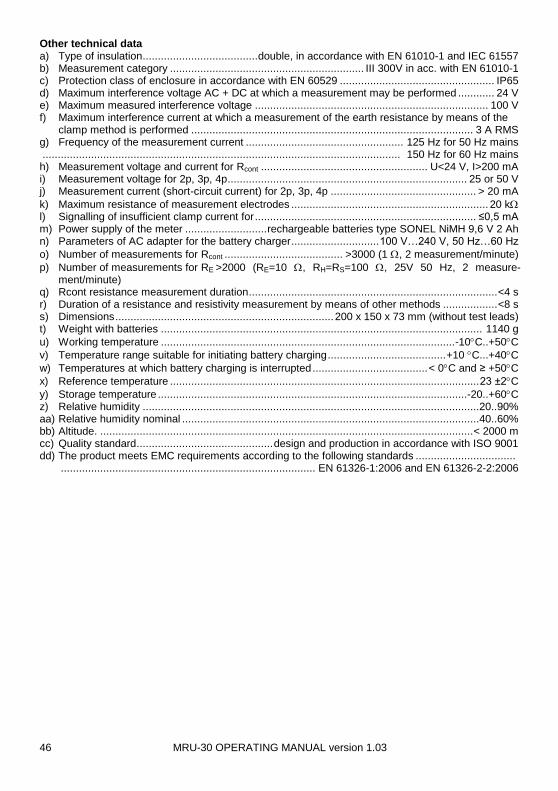
Other technical data a) Type of insulation ...................................... double, in accordance with EN 61010-1 and IEC 61557 b) Measurement category ................................................................ III 300V in acc. with EN 61010-1 c) Protection class of enclosure in accordance with EN 60529 ................................................... IP65 d) Maximum interference voltage AC + DC at which a measurement may be performed ............ 24 V e) Maximum measured interference voltage ............................................................................. 100 V f) Maximum interference current at which a measurement of the earth resistance by means of the
clamp method is performed ............................................................................................. 3 A RMS g) Frequency of the measurement current .................................................... 125 Hz for 50 Hz mains ...................................................................................................................... 150 Hz for 60 Hz mains h) Measurement voltage and current for Rcont ....................................................... U<24 V, I>200 mA i) Measurement voltage for 2p, 3p, 4p ............................................................................... 25 or 50 V j) Measurement current (short-circuit current) for 2p, 3p, 4p ................................................ > 20 mA
k) Maximum resistance of measurement electrodes ................................................................. 20 k l) Signalling of insufficient clamp current for ......................................................................... ≤0,5 mA m) Power supply of the meter ........................... rechargeable batteries type SONEL NiMH 9,6 V 2 Ah n) Parameters of AC adapter for the battery charger ............................. 100 V…240 V, 50 Hz…60 Hz
o) Number of measurements for Rcont ....................................... >3000 (1 , 2 measurement/minute)
p) Number of measurements for RE >2000 (RE=10 , RH=RS=100 , 25V 50 Hz, 2 measure-ment/minute)
q) Rcont resistance measurement duration .................................................................................. <4 s r) Duration of a resistance and resistivity measurement by means of other methods .................. <8 s s) Dimensions ........................................................................ 200 x 150 x 73 mm (without test leads) t) Weight with batteries .......................................................................................................... 1140 g
u) Working temperature ................................................................................................. -10C..+50C
v) Temperature range suitable for initiating battery charging ....................................... +10 C...+40C
w) Temperatures at which battery charging is interrupted ...................................... < 0C and ≥ +50C
x) Reference temperature ...................................................................................................... 23 ±2C
y) Storage temperature ......................................................................................................-20..+60C z) Relative humidity ...............................................................................................................20..90% aa) Relative humidity nominal ..................................................................................................40..60% bb) Altitude. ........................................................................................................................... < 2000 m cc) Quality standard ............................................. design and production in accordance with ISO 9001 dd) The product meets EMC requirements according to the following standards .................................
.................................................................................... EN 61326-1:2006 and EN 61326-2-2:2006

MRU-30 OPERATING MANUAL version 1.03 47
12.2 Additional data
Data regarding additional uncertainties are useful mainly in the case the meter is used under non-standard conditions as well as for measurement laboratories for the purpose of calibration.
12.2.1 Influence of the serial interference voltage UZ on earth resistance
measurements for functions 3P, 4P, 3P + clamp, ρ
RE UN Additional uncertainty []
0,00…10,00 25V (0,001RE+0,01)Uz+0,007Uz2
50V (0,001RE+0,01)Uz+0,004Uz2
10,01..2000 Ω 25V, 50V (0,001RE+0,01)Uz+0,001Uz2
2001..9999 Ω 25V, 50V (0,003RE + 0,4)Uz
12.2.2 Influence of the auxiliary electrodes on earth resistance measure-
ments for functions 3P, 4P, 3P + clamp, ρ
RH,RS Additional uncertainty [%]
RH≤5 kΩ and RS≤5 kΩ
)105,1004,0
150100000
(28
H
E
H
S
S RR
R
R
R
RH>5 kΩ or RS>5 kΩ
or RH and RS >5 kΩ )105,1
004,05,7(
28
H
E
H RR
R
RE[Ω], RS[Ω] and RH[Ω] are values which are displayed by the device.
12.2.3 Influence of the interference current IZ on the result of the earth re-
sistance measurement 3P+clamp
The MRU-30 meter may perform a measurement, if the value of the interference current does not exceed 3 A rms and the frequency complies with the value set in the MENU.
RE Additional uncertainty [Ω]
0,00..50,00 Ω )03,0( 2ZE IR
50,01..2000 Ω )0009,0( 2ZEE IRR
2001..9999 Ω ))15(109( 27 ZZE IIR
If the interference current exceeds 3 A the possibility of measurement is blocked.

MRU-30 OPERATING MANUAL version 1.03 48
12.2.4 Influence of interference current on the result of the earth resistance
measurement using double clamps
The MRU-30 meter may perform a measurement, if the value of the interference current does not exceed 3 A rms and the frequency complies with the value set in the MENU.
RE Additional uncertainty []
0,00...10,00 0,03RE2IZ
10,01...99,99 0,0004RE2IZ(IZ+10)
If the interference current exceeds 3 A the possibility of measurement is blocked.
12.2.5 Influence of the relation of the resistance measured with clamp for
the multiple earthing branch to the resultant resistance (3P + clamp)
RC Additional uncertainty [Ω]
≤ 50Ω )003,0(
2W
C
R
R
> 50Ω
)5,0(W
C
R
R
RC[Ω] is the value of the resistance measured with clamps for the branch displayed by the device, and RW[Ω] is the value of the resultant multiple earth resistance.
12.2.6 Additional uncertainties in accordance with IEC 61557-5 (3p, 4p)
Influencing factor Symbol Additional uncertainty
Location E1 0%
Power supply voltage E2 0% ( not displayed)
Temperature E3 ±0,2digits/°C for R<1 kΩ
±0,07%/°C ±0,digits/°C for R≥1 kΩ
Serial interference voltage E4 In accordance with formulas in
10.2.1 (UN=3V 50/60Hz)
Resistance of electrodes and auxiliary earth electrodes
E5 In accordance with formula in
10.2.3
MRU-30 OPERATING MANUAL version 1.03 49
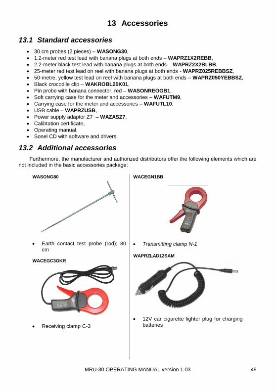
13 Accessories
13.1 Standard accessories
30 cm probes (2 pieces) – WASONG30,
1.2-meter red test lead with banana plugs at both ends – WAPRZ1X2REBB,
2.2-meter black test lead with banana plugs at both ends – WAPRZ2X2BLBB,
25-meter red test lead on reel with banana plugs at both ends - WAPRZ025REBBSZ,
50-metre, yellow test lead on reel with banana plugs at both ends – WAPRZ050YEBBSZ,
Black crocodile clip – WAKROBL20K01,
Pin probe with banana connector, red – WASONREOGB1,
Soft carrying case for the meter and accessories – WAFUTM9,
Carrying case for the meter and accessories – WAFUTL10,
USB cable – WAPRZUSB,
Power supply adaptor Z7 – WAZASZ7,
Calibtation certificate,
Operating manual,
Sonel CD with software and drivers.
13.2 Additional accessories
Furthermore, the manufacturer and authorized distributors offer the following elements which are not included in the basic accessories package:
WASONG80
Earth contact test probe (rod); 80 cm
WACEGC3OKR
Receiving clamp C-3
WACEGN1BB
Transmitting clamp N-1 WAPRZLAD12SAM
12V car cigarette lighter plug for charging batteries

MRU-30 OPERATING MANUAL version 1.03 50
WAFUTL3
80cm test probe (rod) carrying case
LSWPLMRU30
Cramp – WAZACIMA1,
14 Manufacturer
The manufacturer of the device, which also provides warrantee and post-warrantee service is the following company:
SONEL S. A.
Wokulskiego 11 str. 58-100 Świdnica Poland tel. +48 74 858 38 60 fax +48 74 858 38 09 E-mail: [email protected]
Web page: www.sonel.pl
Attention:
Service repairs must be carried out solely by the manufacturer.
MRU-30 OPERATING MANUAL version 1.03 51
15 Testing and Calibration Laboratory
Research and Calibration Laboratory of SONEL SA offers calibration of the following instruments
used for electrical/non-electrical measurements: - meters for electrical protective measurements: insulation resistance, impedance and resistance
of short-circuit loops, earthing resistances and earth resistivity, RCD parameters and multi-functional meters that perform the above functions,
- electrical safety meters, - multimeters, - power quality analysers, - meters for measuring low resistance values, - infra-red cameras, - pyrometers, - luxmeters.
In addition, the Laboratory performs voltage, current and resistance calibration.
A calibration certificate is a document confirming compliance of parameters declared by the manufacturer of tested device with national standards, specifying the measurement uncertainty.
Pursuant to standard EN ISO 10012:2003 "Measurement management systems — Require-ments for measurement processes and measuring equipment", SONEL S.A. recommends for its in-
struments to be periodically tested, observing the interval of 13 months.
For new devices with calibration certificates, the next metrological inspection (calibration) is rec-
ommended within 13 months from the date of purchase, but not later than 19 months from the date of manufacture.
Note:
In case of instruments used for tests related to the protection against electric shock,
the person performing measurements should have complete confidence in the effi-
ciency of operated apparatus. Measurements carried out with malfunctioning meter
may cause wrong assessment of tested equipment in terms of its protection features

MRU-30 OPERATING MANUAL version 1.03 52
NOTES


