OPERATING MANUAL KILNMASTER CONTROLLERS · PDF fileOPERATING MANUAL KILNMASTER ®...
56
KILNMASTER ® AUTOMATIC KILNS OPERATING MANUAL KILNMASTER ® CONTROLLERS EDITION 4 MAY 2002
Transcript of OPERATING MANUAL KILNMASTER CONTROLLERS · PDF fileOPERATING MANUAL KILNMASTER ®...
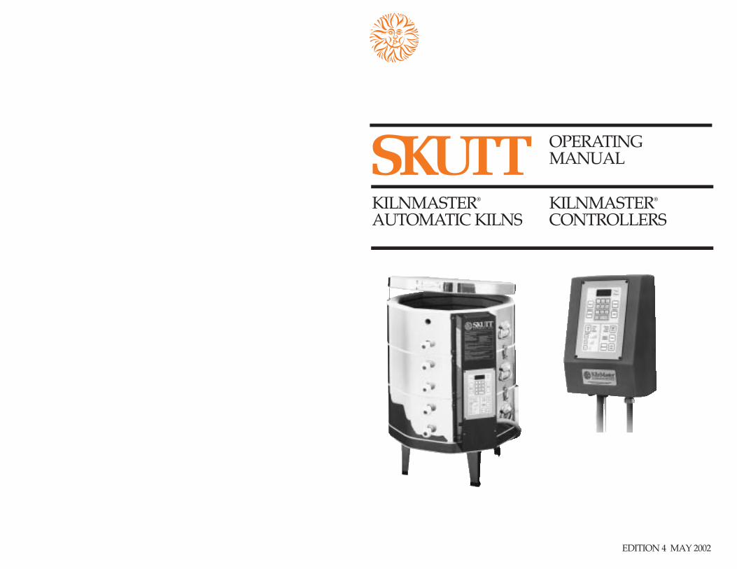
KILNMASTER®
AUTOMATIC KILNS
OPERATING MANUAL
KILNMASTER®
CONTROLLERS
EDITION 4 MAY 2002

KilnMaster® and EnviroVent® are registered trademarks ofSkutt Ceramic Products, 6441 S.E. Johnson Creek Blvd.,Portland, Oregon 97206-9594 Phone (503) 774-6000 FAX (503) 774-7833 © Copyright 1998. Skutt CeramicProducts. Printed in U.S.A.
Table of ContentsQuick Start........................................................ 1
The Cone Fire Mode................................... 1The Ramp/Hold Mode............................. 2
Introduction...................................................... 3Features of the KilnMaster ....................... 4Skutt kiln/controller features.................. 5
Wall Mounted KilnMaster........................... 5Controller set up.......................................... 6 Thermocouple.............................................. 7Kiln settings .................................................. 7KilnMaster repairs ...................................... 7
Automatic Kiln set up................................... 8Locating your new kiln ............................. 8Unpacking and checking the kiln .......... 8Electrical requirements............................ 10Preparation before firing......................... 11First test firing ............................................ 11
General Ceramic Information................... 12Precautions.................................................. 13Loading: key to consistent results........ 13Greenware for bisque firing................... 13Glaze firing.................................................. 14Porcelain and stoneware firings ........... 14Overglaze firings....................................... 14Glass fusing & sagging firings .............. 14
General Firing Information ....................... 15Pre-firing checklist .................................... 15Cold weather operation.......................... 15Type of firing.............................................. 16Venting......................................................... 16
Underglaze firing................................... 16Ceramic glaze firing.............................. 16“Greenglaze” one-fire ceramics......... 16Overglaze fires........................................ 16Firing porcelain ...................................... 17Firing stoneware .................................... 17Firing glass............................................... 18
Quick cone reference chart..................... 18The KilnMaster Controller......................... 18
During the firing ....................................... 18After each firing......................................... 18Cone Fire Mode......................................... 19
Profiles....................................................... 19Programming.......................................... 21Programming step by step ................. 22
Ramp/Hold Mode................................... 23Programming.......................................... 24Programming step by step...................24Programming examples...................... 26
Key Functions of the Controller............... 28Temperature Scale Selection.................. 28Delay Start................................................... 28 Alarm............................................................ 28Review.......................................................... 29Cone Table .................................................. 29View.............................................................. 29Powering the Kiln..................................... 30Stop Firing................................................... 30Start Firing................................................... 30
Questions and Troubleshooting .............. 31
Kiln Problems................................................ 31Ware imperfections...................................... 32Repairs............................................................. 34
Wall and slab brick repair .......................34Replacing elements................................... 35Replacing thermocouple......................... 35
Glossary........................................................... 35Appendix 1 Specifications ......................... 37Appendix 2 Cone Chart, Heat Work ..... 37Appendix 3 Display Messages................. 39Appendix 4 Error Messages...................... 40Appendix 5 KM Wiring Diagrams......... 41Appendix 6 KM-1 UL Listing................... 45Appendix 7 PK Production Kilns............ 45Production Kiln Wiring Diagrams.......... 48Index................................................................. 50Ramp/Hold profile masters ..................... 52
About thermocouples.
Skutt KilnMaster kilns are equippedwith MI (mineral insulated) thermocou-ples, which feature long life, virtually noflaking, and ease of installation. Because ofthese improvements, an additional ther-mocouple is not included with your kiln.
Thermocouple wear is progressive, so itmay not be obvious.
Signs that a thermocouple may needreplacing include:
1. A crack in the sheath of the thermo-couple.
2. A FAIL message on the display.3. Erratic temperature swings and/or a
minus sign on the display.4. A change in firing results as evidenced
by overfiring or underfiring.Thermocouple elements are available
from your Skutt distributor or from SkuttCeramic Products if a distributor is notconveniently located near you.
Wall MountedController Thermocouple
Kiln Thermocouple

Quick Start—All you need to startfiring now!If you:• are an experienced electric kiln operator, • know how to set up a new kiln and kiln
wash shelves, • know about doing the first test firing,
and• know how to load your ware—you can use the following Quick StartFiring Instructions.
If this is your first new kiln, please take thetime to read the set up and general ceram-ic information sections of this manual, foryour safety and to ensure proper opera-tion and long life of your quality Skuttkiln.
For those of you who have fired kilnsbefore, this section offers a brief set ofinstructions for programming the con-troller in both Cone Fire and Ramp/HoldModes. Be sure that your kiln is set upproperly and your shelves are kilnwashed.
Please refer to the section on TheKilnMaster Controller for all the features,programming examples and detailedinstructions on using the controller.
QUICK START:THE CONE FIRE MODE
The Cone Fire mode replicates your previ-ous firing experience using cones in a kilnsitter. Use the Hold function to adjustyour final results in the event the shelfcones are slightly underfired. Be carefulnot to add too much time (5-15 minutes isa good start). Please read Appendix 2relating to Cones and Heat Work for moredetails.1. From idle mode, press Enter, then
Cone Fire.2. Enter the Cone number. (Important:
be sure to know the maturing tempera-ture of your clay. For example, a Cone05 is cooler than a Cone 5.) Press Enter.
3. Press one of the firing speeds, eitherSlow, Medium, or Fast. Press Enter.
4. Enter a hold time in hours and minutesor zero for no hold time. Press Enter.
5. The display will flash two times, andthen show the internal kiln temperatureindicating that the kiln is ready to fire.
6. Press Start.
Activate the power source by pluggingin the kiln or controller. “PF” will appearin the display window indicating that thepower has been turned off for more thantwo minutes.
Press Enter to clear the message.The touch pad should now be in IDLE
mode and will now respond to key press-es. The display will flash the internal tem-perature of the kiln, alternately with“IDLE.” The controller is ready to pro-gram when the temperature appears inthe display window. All programmingbegins when the flashing internal kilntemperature is on the display.
To change from the default setting of ˚Fto ̊C, press the degrees F/C key, thenEnter. A decimal will appear in the lowerright corner of the display window whenin the centigrade mode.
You’ll notice different default displays.The Alarm default is 9999. The Delaydefault is 00.00. Numbers to left of thedecimal are hours, to the right are min-utes. Hold default is 00.00, again in hoursand minutes.
1

7
8
5
6
4
1
2
3
HoldTemperatureRateSegment
QUICK START:THE RAMP/HOLD MODE
Important: To effectively use Ramp/Hold mode, it is imperative to under-stand heat work theory. If you know thetheory well, and if you have had experi-ence with other programmable kilns orcontrollers, then the Quick Start instruc-tions at right will be useful.
If not please read the completeRamp/Hold instructions beginning onpage 23, and Appendix 2 for details.
6. Enter the amount of hold time inhours and minutes, or zero for no holdtime. Press Enter.
7. Repeat instructions 4-6 for each seg-ment that will be programmed.
8. Enter the ALAr alarm temperature, orleave at the default setting of 9999 bypressing Enter.
9. The display will return to idle mode.10. Press Start.
2
The Ramp/Hold mode can be used for allfiring applications from glass to high fireporcelain and stoneware. This optionallows you to create your own profileswith up to eight ramp and hold segments.Each segment has three components: heat-ing rate, temperature and hold. If you areprogramming to approximate cone num-bers, be sure to review the Appendix 2 forinformation on heat work.
Before you begin input, create a chartwith all of the segments you plan toinclude in your program. You may havefewer than eight segments, but no more.Select either ˚F/˚C before you begin.
One can store up to six programs in per-manent memory by assigning a USErnumber (program number) beforeinputting the required data. The next timethat program is desired, simply select theappropriate USEr number. When all USErnumbers are programmed, it will be nec-essary to write over an existing number,which will erase it from memory.
1. From idle mode, press Ramp/Hold.2. Enter the USEr Number of the pro-
gram you wish to fire. If none has beenentered, select 1. Press Enter.
3. Enter the number of segments inyour program. Press Enter.
4. Enter the first heating rate in degreesper hour. Press Enter.
5. Enter the first temperature to reach.Press Enter.

The Skutt family ofautomatic kilns.INTRODUCTION
Congratulations! You’ve made a greatchoice from the proven Skutt kiln line. First, read this entire manual before youdo anything else. At Skutt CeramicProducts, we created and refined themulti-sided electric kiln. And althoughthere are many imitators, frankly we stillbelieve that no kiln is designed with moreunderstanding or manufactured withmore care. Even so, for complete safetyand consistent results, you must under-stand the principles behind ceramic firingand how your kiln works.
Whether you have owned an electrickiln before or not, please take the time toread this manual from cover to cover. Wethink even the most experienced veteranwill learn a few new tips.
This manual covers Skutt AutomaticKilns with built-in KilnMaster Controllersand wall-mounted KilnMaster Controllersfor conventional kilns. Because both unitshave the same electronic functions, whenwe say “KilnMaster” or “controller” weare referring to the touch pad on either thekiln or the wall-mounted version.
3

failure. This feature also permits you tostore up to six Ramp/Hold programs inmemory, and to use them later by enter-ing their program number.Delay firing start. You can delay the startof a firing for up to 99 hours and 99 min-utes.Controlled cooling rate. Now you canprogram your own rate of cooling toachieve your specific results.Program Review Option. The programyou have entered can be reviewed beforeand during a firing. Pressing the Viewbutton displays the segment that is cur-rently being executed during Ramp/Holdmode firings.Cone table. This function shows you theequivalent temperature in degreesFahrenheit or Centigrade that correspondsto a cone number, which is handy whenprogramming Ramp/Hold firings.Fahrenheit or Centigrade operation.Select either temperature scale at the touchof a button. Permanent memory allowsthe temperature scale and values to becontinuously displayed until repro-grammed.Programmable High TemperatureAlarm. The program lets you set an alarmthat will alert you when a specified tem-
perature has been reached. This allowsyou to check firing progress and to be pre-sent as shut-off or ramp-down occurs.Safety Features. Power failure detection.Firing will continue after power interrup-tions which cause less than a 250 ̊F dropin internal temperature. Firing will alsocontinue in Cone Fire mode if the inter-ruption causes less than a 100 ̊F drop dur-ing the final 100 ̊of a firing.Thermocouple failure detection. The con-troller can detect a failed thermocoupleand will turn the kiln off automatically.Controller-operation failure detection. Ifa fault is detected in the controller the kilnwill turn off automatically.Designed and Manufactured in theUnited States. Licensed under Orton’sPatent #4461616. In Cone Fire mode, thecontroller uses Orton’s patented methodto adjust final temperature to emulatecone “heat work”. This is fully describedin Appendix 2, Cone Chart and HeatWork. UL and CSA Listed. The KilnMasterController is UL and CSA listed when fac-tory installed in Skutt automatic kilns andwhen the wall-mounted KM-1 KilnMasterController is used with the UL-listed Skuttkiln models listed in Appendix 6.
Features and benefitsof the Skutt KilnMastercontroller.Easy to use. The display guides youthrough operating steps by a series ofmessages that ask for information. Theinternal temperature is displayed duringthe entire firing and during the cooling.Program by cone number. Simply select acone number from the table and enter thespeed you want for firing. The lower lefthalf of the touchpad controls the ConeFire functions; the right side controlsRamp/Hold functions. Review is appro-priate for either mode.Firing speed options. When firing fromthe Cone Fire mode, you can select fromthree preprogrammed ramp speeds: fast,medium or slow. Multiple Ramp/Hold segments. Whenfiring in the Ramp/Hold mode you canprogram up to eight different segmentsthat include rate, temperature and holdtime.Permanent program memory. Permanentmemory allows the controller to maintainvalues in the memory in case of power
4

What you’ll find in a quality Skutt kiln—and why.KilnMaster Controller. At the heart ofyour new kiln, or wall mounted KM-1, isthe KilnMaster controller. This unit allowsyou much greater control over your kilnthan ever before. It is essentially two con-trollers in one. You can fire by cone num-bers or specify your own firing profilewith multiple ramps & holds.Brick. Skutt kilns are constructed of thefinest insulating firebrick available today,offering strength, cleanliness and long life.All bricks are precision cut and grooved toassure tight fit, perfect element supportand ease of replacement. Because of theirporous composition, insulating fire brickare fragile. Always handle your kiln andits brick with care. The brick in your kilnmay begin to show some fine cracks afterthe first few firings, especially after Cone10 high firings. This is normal and doesnot harm the structural integrity of thekiln or impair its functioning.
5
Elements. The highest quality iron-alu-minum-chromium (Kanthal-type A-1) ele-ment wire is used in all Skutt kilns.
Element life will vary depending onwhether the kiln is used primarily for lowfiring of bisque or greenware, or high fir-ing of stoneware and porcelain. Elementswill last for many firings if treated carefully.
Remember these points.1. Keep the element grooves free of debris:bits of bisque, glaze, cones, metal or highfire kiln wash will immediately fuse to anelement and proceed to eat through it.Kanthal elements become brittle afterrepeated firings, so be extremely carefulnot to scrape against them.2. Do not attempt to fire beyond the ratingon your kiln.Stainless steel jackets. Only the finestgrade stainless steel is used in Skutt kilnjackets, selected for its expansion qualitiesso that the bricks are never undulystressed, yet are fully supported during allstages of heating and cooling. Stainlesssteel may discolor with repeated heating.Stainless steel cleaner is available.Lid brace. The lid brace holds the lidsecurely open for loading and unloadingthe kiln. As you open the lid, allow the lidbrace to follow over the anchor pad andscrew that is attached to the side of thekiln. Simply allow the notched end of thebrace to engage the anchor pad and screw,allowing the lid to rest in a full uprightposition. Periodically test the thumbscrewfor tightness. If loose, tighten.Modular design. Larger Skutt kilns usestackable ring segments which makesthem easier to move and allows betteraccess to elements and firebricks.
The Wall-mountedKilnMaster Controller. The wall-mounted KilnMaster functionsin the same manner as the kiln-mountedversion with the exception that it can bemoved from one kiln to another. Whilethe wall-mounted version cannot firemore than one kiln at a time, it can controlvirtually any kiln in a studio which hasthe proper cord plug and receptacle con-figuration.

The Wall-MountedKilnMaster ControllerThe wall-mounted KM-1 KilnMaster givesautomatic kiln control to most modernSkutt 208/240V kilns and any other brandkiln which uses NEMA 6-50 (single phase)or NEMA 15-50 (3 phase) plugs andreceptacles. It can control virtually anykiln in a studio which has the proper cordplug and receptacle configuration.
Once installed, the KilnMaster controlleruses the same operating instructions asother Skutt Automatic kilns.
6
Locating the controller. Pick a locationthat will put the controller at least two feetfrom the kiln to prevent overheating thecontroller.
Mounting the controller on the wall.Mark the hole positions on the wall wherethe controller will be installed using thepaper template supplied with the con-troller. To mount the controller on stud or post:1. Use the holes marked “A” on the tem-
plate and screw a #12 x 2” wood screwinto the wall leaving a 1/8” gap.
2. Repeat for the second screw.
To mount the controller in sheet rock:1. Using holes marked “A” and “B” on the
template, drill the necessary holes toproperly mount the 1/4” x 2” mollybolts into the sheet rock.
2. Tighten the first bolt until there is a 1/8”gap.
3. Repeat for the other three molly bolts.
Before hanging the controller on the wall,loop the cord attached to the quick refer-ence card over a screw so that it hangsbelow the controller when mounted.
CONNECTING TO THE KILN.
Single Phase. (Switching capacity 48Amps on 208-240V) To operate the wall-mounted controller, simply engage thekiln plug in the receptacle located on theback of the controller. Then plug the con-troller into the existing wall receptacle.Three-phase. (Switching capacity 40Amps on 208-240V) To connect yourthree-phase kiln, plug the power cordfrom the kiln into the receptacle mountedon the back of the controller as shownbelow. Plug the pilot cord (the smallercord) into the small receptacle mountedon the underside of the controller. The

controller is plugged into a wall receptaclewhich provides three phase voltage.You will no longer need to use the three-phase contactor box. However, an electri-cian may need to wire a receptacle for thecontroller if a three-phase contactor boxwas used previously. You may need tomake other changes to the supply for kilnsnot made by Skutt. Other manufacturersmay not use pilot cords. Please discussthis with your distributor.Thermocouple mounting. Skutt kilnshave a hole stamped in the stainless bandwhere the thermocouple flange should bemounted This hole is located to the rightof the red switch boxes. You can see thefirebrick through this hole. The thermo-couple flange is a metal tube approximate-ly 5/8” in diameter and 1 1/2” longattached to a metal washer.1. Remove the thumbscrew from the
flange.2. Align the thermocouple flange so that it
is exactly over the hole in the stainlessband. Position the flange so the thumb-screw is on the top. Attach the flange tothe kiln using the two Phillips self-tap-ping screws provided. Note: To start thescrews, lightly hit each screw with ahammer until the point has pierced thestainless steel band.
3. Insert a 1/4” twist drill or carpenter’s bitthrough the flange holder. Slowly drillthrough the kiln wall brick into the kilnchamber as shown at right.
4. Insert the thermocouple into the kiln sothat 1-1/4” to 1-1/2” of the tip pro-trudes into the kiln chamber. Tightenthe thumbscrew.
5. Uncoil the yellow thermocouple wirethat is hanging from the bottom of thecontroller enclosure. Next, take thereceptacle on the end of the wire andengage it with the two prongs on thethermocouple which you mounted onthe flange in Step 4. There is only oneway the plug will engage the receptacle.
6. The controller is now ready for use.
If you are installing the thermocouple on akiln that is not marked for a thermocou-ple, please follow these instructions.1. Mark a 1/2 to 5/8” diameter hole on
the stainless jacket in the center of thebrick next to the Kiln-Sitter brick (onebrick to the right of the master switch-box). Be sure placement is accurate sothat you do not drill through an ele-ment. Do not drill yet.
2. Align the flange holder accurately overthe mark, positioning the thumbscrewhole on top. Mark the position of thesmall holes on the jacket. Push hard ortap out with a nail and hammer thesmall screw holes. Drill two 3/32” holesfor the smaller sheet metal screws. Drillthrough the metal only. Install the flangewith the sheet metal screws provided.
3. Follow steps 2-6 above.
KILN SETTINGS
The kiln switches, Kiln-Sitter and limittimer (if so equipped) need to be properlyset and adjusted for correct operation withthe controller. Please follow the instruc-tions for the option(s) that apply to yourkiln.Kiln-Sitter. The Dawson Kiln-Sitter is nolonger a control device when used withthe KilnMaster controller, but it can beused as a backup safety device. 1. Place a Junior cone one or two numbers
hotter than the cone equivalent you pro-gram into the KilnMaster to keep theKiln-Sitter from shutting off the kilnearly. For example, if you program aCone 5 (2156˚) firing in the KilnMaster,place a Cone 6 or 7 Junior cone in theKiln-Sitter. Use your firing experience orread the relevant sections of this manualfor more information.
2. Push the plunger in. Repeat this proce-dure using new cones each firing.
Limit timer. If your Dawson Kiln-Sitter isequipped with a limit timer, set the timer
for 20 hours (the maximum). Because theKM-1 controller turns the power to yourkiln on and off to control the temperature,the timer will only run intermittently andwill be useless. If you fail to set a maxi-mum time each firing, the timer may shutoff the kiln early. You may want to dis-connect the wires that operate the limittimer to eliminate the bother of resettingthe timer each firing.Switches. The switches on your kiln willno longer be used to control the tempera-ture rise inside your kiln. The KM-1 con-troller now controls the heating rate. Set all switches in your kiln to High.(Exception: do not set the center section ofthe 818-WR above 4. )If you have questions, please call SkuttCeramics at (503) 774-6000. Programming. Refer to the Quick Startsections on Cone Fire and Ramp/Hold forinstructions on programming.
WALL MOUNT CONTROLLER
The KilnMaster contains many compo-nents which cannot be replaced in thefield. Your Skutt distributor may be ableto replace cords, connectors and relays.
The thermocouple can be easily replacedwhen needed:1. Loosen the thumbscrew on the thermo-
couple flange and gently pull the ther-mocouple assembly out of the kiln.
2. Discard the old thermocouple and plug
7
Automatic kiln set up.PLANNING THE LOCATIONOF YOUR NEW KM-SERIES KILN.
Location. For safety and convenience fol-low these basic rules.1. Locate your kiln near your present elec-
trical outlet or where a new circuit canbe installed with least cost. Position thekiln to the left of your electrical outlet sothe cord will have an easy run and willnot place a strain on the plug or outlet.
2. Install it in a well ventilated, shelteredarea such as a carport, garage, utility orhobby room. It should be convenient toyour clay working area, and out of theway of other traffic.
3. Allow at least 18” of space betweenyour kiln and adjacent walls.
4. Keep curtains, aprons, plastic or otherflammable materials away from yourkiln.
5. Never fire your kiln within a four sidedcabinet or closet. The fourth side mustalways be open to room air to preventthe kiln from overheating surroundingsurfaces. It is best to leave at least twosides open for easy access to controlsand peep holes. Fully automatic kilnsshould not be located in a room thatexceeds 105˚F (41˚C) or is less than 32 ̊F(0 ̊C) as damage to the electronic com-ponents may result.
8
6. Always locate the kiln on a non com-bustible floor such as cement or ceramictile.
7. When installing a kiln in a room with afire control sprinkler system, pleasecheck the sprinkler head rating to insurethat heat emitted from the kiln will notactivate the sprinkler system.
UNPACKING AND CHECKINGTHE KILN
Checking your kiln for damage. Yourkiln has usually traveled a long way byrail car or truck to get to you. Even thoughit was carefully packed at the Skutt facto-ry, it could have been mishandled in ship-ping. If you find any problems as youunpack, do this. 1. Call your freight agent and ask for an
inspection.2. Save all the packing materials.3. Contact the dealer where you bought
your kiln.4. Don’t assemble or fire your kiln until
your damage claim has been inspected.Fortunately, few Skutt owners will experi-ence any problems.For information on setting up Skutt PKProduction Kilns, see Appendix 7 beginningon page 45.
Unpacking the kiln.1. The bottom tray of each carton is
attached to a wooden pallet. The kilnrests on foam packing material which ison the bottom tray. The bottom portionof the carton is stapled to the tray. Afterremoving the staples from the tray, thecarton can lift straight up exposing theassembled kiln. There is foam packingmaterial that will fall loose from the kilnwhen the carton is lifted. Remove theplastic sheet and paper shields.
2. Open the lid, remove the plastic coverand carefully remove the kiln stand and“goodie bag” from the inside of the kiln.Close the lid.
3. For larger, heavier kilns you maychoose to remove the lid from the topsection. This will reduce the overallweight. To do this remove one cotterpin from the lid rod and slide the lidrod out of the lid hinge assembly. Alsoremove the thumbscrew and lid brace.Place lid on a clean, flat surface.
4. Remove the black plastic feet from the“goodie bag” and put them on thestand legs. Set the stand in the locationyou have designated for the kiln. Seethe section on locating your kiln if youare not sure about the safety require-ments for the kiln site.
a new MI cable thermocouple into thereceptacle mounted on the cord fromthe Wall Mounted Controller.
If a problem persists, call the factory tomake arrangements for return of parts.When the controller is received we willevaluate the problem and call you with acost estimate.
Send to Skutt Ceramic Products, 6441S.E. Johnson Creek Blvd., Portland,Oregon 97206-9594. Our telephone num-ber is (503) 774-6000, Fax (503) 774-7833.
See page 35 for details on replacing thethermocouple elements on KM kilns,which have a slightly different mount.

9
5. There are section handles on the kiln.With a partner, lift the kiln, using thelower section handles, off the kiln floorand rest on a clean, flat surface.
6. You may separate the kiln into sectionsif it is too heavy to move.
a. The electronic control panel of your kilnhas a hinged box for easy removal.Remove the screws on the left side ofthe box that secure the box to the kiln.
b. Swing the panel to the side.c. Slide the connectors off of the terminals
noting the placement of the wires. Slidethe thermocouple connectors off the ter-minal strip, also.
d.Lift the box up to remove it.
7. Position the kiln floor on top of thestand making certain that the weight isevenly distributed.
8. Level the kiln. Make sure the stand andkiln floor are level and do not teeter.Leveling problems may put unneces-sary stress on the kiln during firing. Tolevel the stand, place firm shims underthe legs (never above them touching thekiln). Center the kiln’s bottom slab onthe stand and double-check teetering.
9. Again, with a partner, pick the kiln upand rest it on top of the kiln floor.
10. Replace the kiln control box on the kilnif removed in step 6 above.
a. Stack the sections on the kiln floor.b. Return the kiln control box to the side of
the kiln.c. Slide the connectors back into place.
Plug thermocouple in.d. Close the box and secure it with screws.If the lid was removed in step 3 above,place the lid on top of the kiln, replace thelid rod and cotter pin and the lid braceand tighten the thumbscrew.11. Place peep plugs in all but the top
peep hole. Always leave the top peephole open to allow vapors to exhaustfrom the the kiln unless you are using afan-driven ventilation system such asthe Skutt EnviroVent®. The EnviroVentallows you to fire with all peep holeplugs installed.
6a
6b
6c

Electrical requirements for Skutt Automatic Kilns and KilnMaster Controller
Model Volts Amps Watts Copper Wire Fuse or NEMA ReceptacleSize* Breaker Size Configuration
KM-614-3 115 20 2300 10 30 (Canada) 5-30KM-614-3 115 20 2300 10 30 5-20KM-714 208-240 20 3600 10 30 14-30KM-818 240 27.8 6400 8 40 6-50KM-818 208 26.7 5550 8 40 6-50KM-818-30A-3 240 21.7 5200 10 30 6-30KM-818-30A-3 208 24.0 4990 10 30 6-30KM-1018 240 38.4 9460 6 50 6-50KM-1018 208 40 8320 6 50 6-50KM-1027 240 48 11520 6 60 6-50KM-1027 208 48 9980 6 60 6-50KM-1027 3ph 240 29.3 11520 8 40 15-50**KM-1027 3ph 208 31.7 11000 8 40 15-50**KM-1227 240 48 11520 6 60 6-50KM-1227 208 48 9980 6 60 6-50KM-1227 3ph 240 29.3 11520 8 40 15-50**KM-1227 3ph 208 31.7 11000 8 40 15-50**KM-1 208-240 Switching Capacity 48 6-50KM-1 3ph 208-240 Switching Capacity 40 15-50
*For each additional 50 feet use heavier wire, numerically two numbers lower—for example,instead of #10, use #8. If you anticipate installing any larger kiln in the future, use the heavier wire. **See special instructions and wiring diagram.
ELECTRICAL REQUIREMENTS
Most important to proper operation ofyour new kiln is to make sure it hasenough of the correct power to operate it.If this is done, your kiln will give youyears of satisfying service; if not, your firstfiring could be disappointing or even dis-astrous for your kiln.The chart at rightshows the recommended electrical specifi-cations for each kiln model. If you areuncertain about your existing outlets, havethem checked by an electrician. If you areinstalling a new receptacle, have the elec-trician follow this guide.
10
ADDITIONAL POWER NOTES
Three-phase operation. Only specialorder Models KM-1027 and KM-1227 willoperate on a three-phase supply.However, any Skutt kiln can be properlypowered via unbalanced connection totwo of the three hot wires of a three-phasesupply. Of course, the green safety groundconnection provided in all Skutt powercords is also used.Three-phase installation. Three-phaseModels KM-1027 and KM-1227 can beplugged directly into a three-phase (15-50R) wall receptacle.208 versus 240 supplies. As you can seefrom the chart, most Skutt models areavailable in either 208 or 240 volt versions.
The exception is Model KM-714 which isuniversal, and will fire with 240V or 208Vpower.
The “120/208V” supply is increasinglyencountered in schools and newly-builtcommunities, because it’s more efficientfor heavy 120V loads.
The 208V versions should never be firedon a 240V supply without first installing afull set of 240V elements. Otherwise, allcomponents will be seriously overtaxed.Conversely, a kiln designed for 240V sup-ply which is powered on a 208V supplywill be severely underpowered.
5-15 5-20 6-30 14-30 6-50 15-50
Important! Connecting and testingModel KM-714. The wall outlets forModel KM-714 must be powered by 3-wire 120/240-208V solid neutral supply—as for an electric range. Only No. 10 wireis required (or No. 8 for runs over 50 feet).30 Amp fuses or circuit breakers only—nolarger or smaller—are recommended. TheU-shaped fourth blade of the 4W30 Ampgrounding plug is for the pure green wiregrounding of the kiln case. The bladeopposite this U-shaped one takes thewhite solid neutral wire. See the diagrambelow and refer to the wiring diagram inAppendix 5 for the 714 plug diagram.
NEMA RECEPTACLE GUIDE.

11
PREPARATION BEFORE FIRING
Remove any brick chips or other foreignmatter from around the elements. Bits ofbisque and glaze will eat through ele-ments and our warranty cannot coversuch accidents. We recommend that youvacuum the inside of the kiln to removeany dust that accumulates during ship-ment.
Wipe all new shelves clean, and brushcoat one side of each with high fire kilnwash. Apply a thin coating of kiln wash inone direction, allow to dry and applyanother thin coating in the opposite direc-tion leaving a 1/2” margin from the out-side edge of the shelf. A new coat is sel-dom needed—just spot-patch and sandoff the surface evenly with coarse sandpa-per wrapped around a wooden block. Afresh coat may be needed before a porce-lain firing if glaze has dripped onto theshelf.
Kiln wash the floor of the kiln, beingcareful to leave a one inch marginunpainted all the way around interioredge. Never kiln wash the walls or lid ofyour kiln!
THE IMPORTANT FIRST TEST FIRING
Now you’re ready to fire. Be sure toreview the preceding sections, doublechecking for safety and correct electricalconnections.
It is important to the life of your kiln thatyour first firing be done properly. Beforeyou start, read this entire manual careful-ly, including the preceding sections andloading and firing instructions.
New elements and foreign matter likedust give off vapors that tend to discolorglazes. Therefore, your first firing shouldbe a Cone 04 empty test fire with only yourdry shelves in the kiln, posted as thoughware were on them. The first time the ele-ments are fired they will give off somesmoke. This is normal and expected. Thisis a good time to use Self-SupportingCones on the shelves to test the heat accu-racy from top to bottom.
A Cone 04 (1944˚) is recommended forproper pre-oxidation of a new element.The steps to accomplish this firing are thefollowing:1. Clear the PF message by pressing
Enter.2. Press Cone Fire mode.3. Press 0 4 then Enter.4. Press Medium speed then Enter.5. Press Enter or an amount of time in
hours and minutes for Hold.6. Press Start to begin the firing.The firing
will take approximately 7 1/2 hours.
Even though you have gone through asimple program for a test firing, pleasecontinue to read the detailed instructionsin the Cone Fire and Ramp/Hold sectionsof this manual.
Periodically view your Self-SupportingCone by removing a peephole plug. Itshould bend to the top of the base (5o’clock position) and the kiln should turnoff about the same time. Watch your kilnthroughout the firing. Don’t rush throughthe first firing. Make notes of things thatyou want to remember and make visualobservations of the kiln while it is firing.
Likely, everything will work as itshould, and you’re ready to go on to pro-duction firings. If things go wrong, re-readthis manual and contact your Skutt dealer.
You will notice a clicking sound whileyour kiln is firing. This is normal. The ele-ments are cycling on and off to stay withinthe temperature parameters you have pro-grammed.
After the first couple of firings, hairlinecracks may appear in the floor of a kiln.This is caused by the expansion and con-traction of the bottom slab caused by heat-ing and cooling, and is considered normal.It will not affect the firing of your kiln northe life of the kiln floor.

12
General CeramicInformationPYROMETRIC CONES
Ceramic firing to the accuracy we knowtoday would be impossible without pyro-metric cones. These long tetrahedrons ofcontrolled composition measure the com-bined effects of time and temperatureaccomplished during a firing. Please referto Appendix 2 which further describes thetheory of heat work. The KilnMasterController uses the patented Ortonprocess of time and temperature when inthe Cone Fire mode. Even though you areoperating a fully automatic kiln, you stillneed to verify the temperature on the shelfusing Self-Supporting Cones.
Senior Cones are designed to be placedstanding in angled holders or Commercialcone plaques or Self Supporting OrtonCones. We recommend using the Self-Supporting Cones that have a precise 8˚angle built into the base allowing the coneto bend properly. When the cones softenand bend to the top of the base (90 ̊is per-fect), the correct firing time and tempera-ture have been reached. It is important
that the cone is standing at the properangle (as precut at the base) for it to bendat its standard temperature.
Obviously, if you wish to monitor firingprogress, Cones must be visible through apeephole.
The traditional and still the most accu-rate method of monitoring a firing is touse three Self-Supporting Cones: the onecalled the guide cone should be one num-ber cooler than your desired firing; the fir-ing cone should be the desired heat, andthe guard cone should be one numberhotter as shown below in a typical exam-ple.
As your firing nears maturity, the guidecone will bend or “drop”. This alerts youto watch the firing cone. If the guard coneis not straight, the best heat work has beenexceeded.
If you discover that your automatic kilnis underfiring ware, check the load in yourkiln to ensure that it is evenly distributedfrom top to bottom. It is easy to program a5 to 10 minute hold at the end of yourCone Fire. The hold can be prepro-grammed or added at the end of a firingschedule. See Cone Fire mode for detailedinstructions.
Cones are sensitive to moisture whenstored and to drafts when firing. Keepthem dry or invisible cracks may develop,causing early bending. If you have a coneproblem, try fresh ones from anothersource. Place cones at least 3” back frompeepholes to avoid a false response to coolair.
At high temperatures cones can be hardto see. Viewing through dark glasses canhelp. Try to keep ware back from cones asfar as possible to avoid a cone melting intothe ware.

13
First, never load damp ware into yourkiln! Make sure it’s all bone dry first.Keep a piece of old greenware on yourdrying shelves. New ware should feel nocooler on your cheek or forearm than anold piece. If it does, water is still evaporat-ing from it.Plan your load carefully. Set out all your
pieces before you start loading, and pre-arrange them as you would to load them.Always load slowly—dropped ware onshelves may damage the inside of yourkiln.
Balance out your load by density. If halfyour load consists of small, heavy pieces,and half of large thin-walled pieces, don’tgroup the small heavy pieces in one sec-tion, but mix them so there is a balance ofeach type throughout the kiln. See thephotos at right. Don’t set pieces of waredirectly on the floor of the kiln. The firstshelf should be 1” off the floor of the kiln.For best results ware should not be placedwithin 1” of the elements. If possible, placeware so that an element groove is underthe shelf.
Don’t place ware too close to the ther-mocouple. We recommend keeping wareand shelves at least 2” away.
Large flat pieces like plates that demandthe full width of the kiln should have theirrims positioned between two elements.We recommend placing a Self-SupportingCone in every firing. Although you nor-mally won’t watch it go down, its condi-tion when you unload the kiln will proveyour firing was correct—or alert you topossible problems if the ware displaysfaults.
GREENWARE FOR BISQUE FIRING
Greenware is easier to handle and loadthan other ware. Greenware should beplaced in the kiln in its natural position,but any large flat piece—such as a wallplaque—can go on its flat side to preventwarping. Canisters and boxes should bebisque fired with lids in place for assur-ance of good fit. For more efficient pro-duction, you may wish to experimentwith nesting bisque, as shown below. Justremember, never strain the rims.
PRECAUTIONS
The controller is a temperature controldevice. It is not a safety device.
The maximum operating temperature is105 ̊F (41˚C). This temperature refers tothe room temperature and does not per-tain to internal temperature of the kiln.
The minimum operating temperature is40 ̊F (4 ̊C). See page 15 for cold kiln roomrecommendations.
The controller contains static-sensitiveparts that may be damaged by static elec-tricity. Use caution to avoid creating staticthat may damage the equipment. In areaswhere static electricity is common, or dur-ing dry times of the year throughout thecountry, touch the kiln lid handle beforetouching the controller to discharge thestatic.
Never leave the kiln unattended at theend of the firing.
LOADING: THE KEY TO CONSISTENT RESULTS
If this is the first firing of the kiln, or if youhave just replaced the elements, please firethe kiln empty to Cone 04.
Careful loading will always be repaidwith satisfaction. Rushed, careless loadingcan bring disaster to pieces you’veworked on for hours.

14
GLAZE FIRING
Glaze firings require that you have kilnwashed the bottom of the kiln and oneside of each shelf. Glaze will stick perma-nently if you fail to keep a good coating ofkiln wash on these surfaces.
Don’t let any of your pieces touch oneanother or the side of your kiln.Stilts are devices used in glaze firing toelevate the fired pieces from the shelves.
There are many styles. Use those thatprovide the widest bearing capacity forstability. If a piece wobbles on its stilts, itmay tumble during firing. Make sure youhave a good solid base.
“Dry-footing” a glazed piece will elimi-nate the need to stilt your ware. To dry-foot, avoid glazing the base of your piece.Or you can apply wax resist to the basewhich will cause the glaze to puddle up,making it easy to remove with a dampsponge. Any part of the ware that willtouch the shelf cannot have glaze on it.
Leave all possible breathing roombetween pieces for best firing uniformity.Ware should be at least 3/4” apart on theshelf or bubbles and fumes may contami-nate adjoining pieces.
PORCELAIN AND STONEWAREFIRINGS
These materials differ only in purity ofclays, although they appear different incolor and texture. By definition, both mustbe fired hot enough to render the bodieswaterproof (or vitreous) at which temper-atures they tend to wilt.
Because the bodies become soft, theymust be bisque and glaze fired resting flaton a freshly kiln washed surface, or onesprinkled with silica flour (flint). Flintmust be kept out of the element grooves.Remember to vacuum the grooves period-ically.
Be sure to check clearance at the top ofyour porcelain load with a ruler so thatpieces do not touch the lid and stick to it.
To avoid distortion, pieces must eitherbe carefully designed or the overhangsspecially supported. Figurine arms aregenerally supported by hollow greenwarepillars, made of the same clay material.These will shrink along with the piece,which in high firings can be as much as 12percent.
Simpler shapes such as wide plate rimsare generally supported by reusable rings(setters) made of even higher firing mater-ial specifically shaped for that one article.
Both porcelain and stoneware glaze fir-ings are dry-footed to prevent fusion tothe shelves.
OVERGLAZE FIRINGS
Stilting may be helpful because it allowsheat to penetrate between the ware andthe slower-heating shelves. Large double-pointed stilts can be used to hold platesapart when fired on edge.
GLASS FUSING ANDSAGGING FIRINGS
When firing with more than two shelves,the lower one is usually posted well offthe kiln floor and the upper one is placedat least 3” above the first mold. The centerof the load should fall a bit above the cen-ter of the kiln.

General FiringInformationWhen firing a new kiln or one that hasundergone repairs or disturbance, placeand watch a Self-Supporting Cone at threelevels within the kiln chamber.
If you are ever in doubt about a firing,simply press STOP or unplug it. Neverchance ruining an entire load of ware ifsomething has toppled off its stilts, if youhear odd noises, or if the kiln has beenjarred. You won’t harm your ware byshutting the kiln off before maturity.Simply set fresh Self-Supporting Cones onthe shelves and begin again. (If you’re fir-ing with a KM-1 wall-mounted controller,replace the Junior Cone in the Kiln-Sittereach firing.)
Because you will keep the top peepholeunplugged during the entire firing, neverunplug any of the lower peepholes formore than a few seconds. This causes astrong convection “jet-draft” which caneasily fracture ware and chill the cones inthe kiln, particularly visible cones placedbehind that particular peephole.
To determine the adjusted end firingtemperature in Cone Fire Mode, pressEnter to get a blinking temperature, thenpress Review. (In Ramp/Hold Mode, thisprocedure will flash back the program justfired.)
PRE-FIRING CHECKLIST
Load kiln.❏ Set Self-Supporting Cones while load-
ing. See loading instructions for moredetailed information.
Kiln ventilation.❏ The lid needs to be propped 2 1/2”
until the internal temperature of thekiln reaches approximately 1000˚F, atwhich time it is lowered.
❏ If you are using a positive kiln ventila-tion system such as the SkuttEnviroVent, the lid does not need to bepropped and peep hole plugs remain inplace throughout the firing. Refer to theEnviroVent instruction manual forcomplete details.
❏ Suggestion: You may wish to place afinal kiln shelf on posts above your loadto deflect any cool air coming in fromthe top of the kiln
❏ Before firing, plug peepholes except thetop one, which is always left open. Thiswill allow fumes to escape. (Not neces-sary when using the EnviroVent.)
Firing speed.❏ Keep in mind the heating rate for each
of the speeds: slow, medium and fast.Consider that the best firing time isfrom 6-8 hours for a Cone 04-06 bisqueor glaze firing.
❏ Using this information, program thekiln for the firing cycle that best suitsthe ware you are firing. See TheKilnMaster Controller section for detailedinformation regarding programming.
Wall mounted controllers.❏ Kilns with a limit timer need to be set
for 20 hours when operating with theKilnMaster controller.
❏ Use a Junior cone one to two cones hot-ter in the Kiln-Sitter as a backup for thecontroller. See the section on the WallMounted KilnMaster Controller formore specific information.
Caution:While the KilnMaster has an excellentoperating record, we recommend thatyou do not leave the kiln unattendedduring firing.
COLD WEATHER OPERATION
While it is possible to operate aKilnMaster-controlled kiln in cold weath-er, the relays which must open and closefreely can tend to stick at low tempera-tures.
We recommend that your work space beheated to at least 40 ̊F for properKilnMaster operation.
If the temperature in your kiln area isnear or below freezing (32 ̊F), use a spaceheater or hair dryer to gently prewarm thecontroller box and thermocouple to 40˚before starting the firing program.
15

16
TYPE OF FIRING
This section gives you some useful tips forvarious types of firings. Please keep thisinformation in mind as you program theKilnMaster.Venting.The use of a positive flow downdraft kilnventilation system such as Skutt’sEnviroVent pictured at right keeps the liddown and all peep hole plugs in placethroughout the firing. This will providemany benefits, such as:• a healthy work environment by remov-
ing fumes from work area • more even heat distribution from top to
bottom of kiln• less color migration between glazes• eliminates the necessity to lower the
kiln lid during firing• improves the end firing results of red
glaze.The most convenient feature is not havingto lower the kiln lid during firing.
Underglaze firing.Greater detail can be preserved in conven-tional and one-stroke underglaze decora-tion if it is first set by an 019 firing beforeglazing and then glaze firing. If the deco-ration was applied directly to greenware,the underglaze fire acts as the bisque, andtherefore should be a full Cone 04 firing.
Ceramic glaze firing.Warning: Use only lead-free or lead-safeglazes on any surface which may come in con-tact with food or drink.
If your ware has been fired to Cone 03 or04 and is properly glazed, dried, andloaded, an 06 or 05 low glaze fire or 6 to 10high fire will normally produce a flawlesssurface. If not, consult the ware imperfec-tions section of this manual.
Crystalline glazes often require specialfiring to develop fully—including a soak-ing period at slightly reduced heat aftermaturity is reached. Experimentation isgenerally needed to discover the correctamount of soak time and correct soaktemperature for your glaze formulation.Once your firing schedule is perfected,store it in permanent memory inRamp/Hold mode.
“Greenglaze” one-fire ceramicsWith the talc clay bodies and preparedglazes available to the ceramist today,some prefer to “one-fire” their ceramics. Insome instances you can satisfactorily glazea piece of greenware and complete it in asingle firing, maturing the clay body andthe glaze at the same time. However,because there may always be residualmoisture in the clay body, persistent cra-tering and pin holing may occur, as wellas off-color spots from impurities burningout of the clay. Fire to at least Cone05, or preferably to Cone 04.
Overglaze fires.China paints. If fired too hot, fine detailwill be blurred. If fired too cool, chinapigments will not be absorbed into theglaze and will quickly wear off. Fire untilthe paints acquire a sheen similar to thesurrounding glaze. With practice, this can
be judged through the peephole. By set-ting a group of guide cones, you can notewhich cone is down when the sheenmatches, so you can program exactly tothis cone the next firing.
This temperature will vary over severalcones if widely different colors are used.High quality will be achieved only byapplying and firing the higher tempera-ture colors first, followed by lower tem-perature ones. The required temperaturealso varies with the softening temperatureof the parent surface.
For ceramic and porcelain articles otherthan tableware, a single Cone 019 firingwill often be a good compromise.
Metallics (gold, platinum, copper, andother). These will fire dull if applied toosparingly, or if underfired. Overfiring,particularly of larger areas, results in retic-ulation or “crocking”—shrinkage of themetal, leaving a network of glaze linesexposed. Greater overfiring results first inspotty, then total disappearance of metalthrough vaporization. On ceramics andporcelain start with Cone 019. Metallicsand green glaze are usually incompatible.

17
Lusters. Luster may flake off if appliedthickly and will “frost” if overfired. Tostart over, fire to 06-05. Keep ware wellaway from kiln elements. Fire to 019 fordurability, drop to 020 if frost is encoun-tered. Lusters are extremely sensitive tocontamination by kiln vapors, particularlythose from greens, and lid ventilatingmust sometimes be continued at 1/2” or1” throughout the firing.
Overglaze. Breakage of ware during over-glaze firings can usually be traced toroughly-handled, unevenly-dried orunevenly-sponged greenware. In general,there is less trouble with art porcelain thanwith ceramic pieces, and least with highquality, pre-glazed, dry-footed importedchina blanks.
Firing schedules for overglazes can usu-ally be accelerated because the ware isentirely free of moisture. A fast firing ratewill be appropriate for this type of ware.The lid remains propped until the odorfrom the burning medium is no longerdetected. Under-ventilation is the biggestcause of problems. Of course, if you arefiring with an EnviroVent, this will not bea concern.
Firing porcelain.Art porcelain should be bisque fired toCone 5 or 6 (not 05-06) in your Skutt kilnunless glaze is to be applied, in which casea soft 05 or 06 non-vitrifying fire is appro-priate. Ware should be loaded and sup-
ported as noted in the loading instruc-tions. Begin lace fires with the lid postedopen 2 1/2”. Optimum quality can beachieved several ways:1. By not loading the kiln very heavily
with ware or extra shelves.2. By bisque firing twice; one to the firing
temperature of the clay, and another toone cone equivalent cooler. Wet-sand-ing with a fine grit silicon carbide paperbetween firings will maximize smooth-ness in the finished piece.
3. “Soaking” for 30-45 minutes slightlylower than the maturing temperaturewill add sheen to the porcelain. Theprocess for soaking is discussed in thesection about glaze firing.
Porcelain glaze is usually fired to maturityof the clay and dry-footing is still essential.
Overglaze decoration is fired exactly aswith ceramics, but usually 2 to 4 coneshotter (017-015) to produce penetration,gloss and durability on the higher-soften-ing glaze. Overglazes are also frequentlyapplied directly to porcelain bisque that isto remain unglazed. Fire to the abovecones.
Firing stoneware.Most Skutt kilns (except a few 208V mod-els and KM-614-3) can attain Cone 8 orCone 10. Because stoneware shapes aredesigned for self-support during firing,the glaze can be matured at the same timeas the body, particularly because the pin-holes, sunbursts and scumming whichtend to accompany one-firing are oftenhighly prized in stoneware. Pieces are dry-footed, of course, and loaded as previous-ly described.
The procedure for stoneware differsfrom that for one-fire ceramics in that theplain or decorated greenware is usuallyfirst given a low bisque firing to Cone 016-04 before glazing. Due to the ware’s thick-ness, the firing rate must be much slowerand more prolonged than in other types ofware.
While the typical overglaze decorationsare rarely considered suitable onstoneware, Cone 06-04 reds, oranges andcrackles are sometimes added after firingto provide effects unobtainable at thehigher temperatures. Warm (130˚F/54˚C)the vitrified ware to facilitate applicationof glaze.

18
Firing glass.Sagging of sheet glass and bottles is car-ried out in terra cotta molds dusted withwhiting (calcium carbonate) or one of sev-eral similar tradename separators. Use theRamp/Hold Mode for glass sagging. Thiswill allow you to program your own spe-cific rate of climb and hold temperatures.Glass decoration can often be carried outwith conventional china paints, metallics,and lusters when the glass is being fired tosagging temperatures. Freestanding tum-blers and other vessels can rarely be takenabove Cone 022 without wilting, so atsuch low temperatures the special glassstains, golds and lusters produce moredependable results.
The KilnMasterControllerDURING THE FIRING.
What you’ll see is the internal temperatureof the kiln displayed in the window of thecontroller as the temperature increases.The options available during the firing are:• Review program at any time.• View Current Segment of Ramp/Hold
Program.• Press Stop to interrupt a firing for any
reason.Please refer to the Key Functions sectionof the manual for detailed explanations ofthe functions.
AFTER EACH FIRING.
1. When the firing is completed, the dis-play will alternately indicate “CPLt” forcomplete and show the firing time inhours and minutes. Press Enter to dis-play the current internal temperature.In Cone Fire Mode, the KilnMaster willadjust the shutoff temperature to corre-spond to the actual heating rate the kilncan achieve. This may or may not be theprogrammed value. To see the adjustedvalue, press Review immediately afteractivating the touch pad.
2. Allow the kiln to cool naturally. Neverunplug other peepholes or post the liduntil the ware is cool enough for bare-handed unloading, about 130˚F.
3. When unloading, be sure to examinethe Self-Supporting Cones on the shelfto determine if the kiln is firing correct-ly.
Quick Reference Chart
STONEWARE
PORCELAIN
PORCELAINGLAZES
CERAMICBISQUE
ANDGLAZE
CHINAGOLDLUSTERSGLASS
RE
D H
EA
TO
RA
NG
E H
EA
TY
EL
LO
W H
EA
T
Tem
pera
ture
016
017
018
019
020
021
022
06
05
04
03
02
01
1
2
3
4
5
6
7
8
9
10

19
Hold
0
0
0
0
0
Temperature
250 ̊F
1000 ̊F
1300 ̊F
1685 ̊F
1938 ̊F
Rate
80˚/hr
250˚/hr
150˚/hr
180˚/hr
80˚/hr
Segment
1
2
3
4
5
200018001600140012001000
800600400200
00 2 4 6 8 10 12
Tem
pera
ture
(˚F)
Hours
250˚
1000˚1300˚
1685˚1938˚
Cone 04, Slow Speed
Cone Fire Mode
DescriptionThe Cone Fire mode is extremely easy touse but gives you access to manyadvanced features. You only have to enterthree pieces of information—cone num-ber, speed, and hold time. Cone valuesrange from Cone 022 through Cone 10.Entering a cone number causes the con-troller to look up the final temperature ina 108˚F/hr Cone Table. You have threespeeds to choose from, slow, medium, orfast. The speed chooses a ramp profile asdescribed below. Also, the Cone Firemode allows you to specify a hold time atthe final cone temperature. It is also possi-ble to program a preheat or “soaking”period to insure all the moisture is elimi-nated from the ware prior to running thefull program.
The Cone Fire mode uses a methodpatented by The Edward Orton Jr.Ceramics Foundation that measures therate of firing during the last hour of the fir-ing and adjusts the final temperature tothe correct cone temperature based on theobserved firing rate. This will insure con-sistent results as the kiln elements becomeweaker with normal wear from repeatedfiring.
PROFILES
Cone Fire–SlowSlow is for hand thrown pottery, porce-lain, and stoneware. The firing will take 12hours* to complete. If you were to pro-gram the segments for this firing, theywould look like the chart at right; howev-er, they are automatic.
The graph at right illustrates the seg-ments of a cone 04 firing in Cone Firemode, slow speed. The firing will takeapproximately 12 hours to complete. Theheating rates are the same for all cones.The temperature in segment 4 is 250 ̊lessthan the final temperature for the cone.
*Firing times are approximate, based on abeginning temperature of 70˚F/21˚C firing toCone 04.

Hold
0
0
0
0
0
Temperature
250 ̊F
1000 ̊F
1150 ̊F
1694 ̊F
1946 ̊F
Rate
200˚/hr
400˚/hr
180˚/hr
300˚/hr
120˚/hr
Segment
1
2
3
4
5
Cone Fire–MediumMedium is the speed you will probablyuse for your firings of cast earthenwareand low-fire glazed pieces. It will takeapproximately 7.5 hours* to fire. The actu-al time is dependent on the selected conevalue. Use this speed when the kiln ispacked tighter or your greenware hasthicker sides or a higher moisture content.If you were to program the segments forthis firing, they would look like the chartat right.
The graph at right illustrates the seg-ments of a cone 04 firing in Cone Firemode, medium speed. The firing will takeapproximately 7.5 hours to complete. Theheating rates are the same for all cones.The temperature in segment 4 is 250 ̊lessthan the final temperature for the cone.
200018001600140012001000
800600400200
00 2 4 6 8 10 12
Tem
pera
ture
(˚F)
Hours
250˚
1000˚1150˚
1694˚1946˚
Cone 04, Medium Speed
*Firing times are approximate, based on abeginning temperature of 70˚F/21˚C firing toCone 04.
20

21
Cone Fire–FastFast is a speed that will take approximate-ly 4 hours* firing depending on the coneselected. Fast speed is probably not thebest choice to use during a bisque firing asit does not allow enough time for thephysical water to burn off and the struc-tural changes to occur. If you were to pro-gram the segments for this firing, theywould look like the chart at right:
The graph at right illustrates the seg-ments of a cone 04 firing in Cone Firemode, fast speed. The firing will takeapproximately 4 hours to complete.
If Review is pressed near the end of thefiring (within one hour of completion) anadjusted cone temperature of 1937 ̊forCone 04 will be displayed. For moreexplanation, see Appendix 2, Cone Chartand Heat Work. This section explains whythe end temperature may be higher orlower than the cone table indicated.
*Firing times are approximate, based on abeginning temperature of 70˚F/21˚C firing toCone 04.
Hold
0
0
Temperature
1704 ̊F
1957 ̊F
Rate
570˚/hr
200˚/hr
Segment
1
2
200018001600140012001000800600400200
00 2 4 6 8 10 12
Tem
pera
ture
(˚F)
Hours
1704˚1957˚
Cone 04, Fast Speed
PROGRAMMING IN THECONE FIRE MODE.
Messages and prompts in the Cone FireMode.A word about the funny digital characters:they may seem unreadable now, butyou’ll get used to them.PF Power Failure, may indicate that thecontroller was just plugged in. Press Enterto clear the PF message and display inter-nal kiln temperature.HOLd Hold time desired at end of firingis entered in hours and minutes up to amaximum of 99 hrs. 99 mins. To enter,numbers on the right of the decimal areminutes, to the left are hours. The defaultsetting is 00 hrs. 00 mins.ConE Requests firing cone number. Besure to enter the correct number keepingin mind that cooler firing temperatureshave a “0” in front of the number.SPd Requests the speed of firing, eitherslow, medium or fast.IdLE When idle is flashing alternatelywith the internal temperature of the kiln,the kiln is in IDLE MODE and ready topregram.(Continued overleaf)

CPLt Indicates that the firing cycle iscomplete. Elapsed firing time in hours andminutes is displayed.-ON- Briefly displayed indicating that thekiln has started.deLA Indicates the amount of time inhours and minutes to delay the start of fir-ing. A maximum of 99 hrs. 99 mins. isallowed. Digits to the right of the decimalare minutes, to the left are hours.ALAr Signals the operator that the kilnhas reached a pre-programmed tempera-ture. The default setting is 9999˚F for noalarm.PrHt Requests a preheating time beentered.
Step Press Action Display1 Cone Fire Enters Cone Fire Mode ConE2 0 6 Enters Cone number desired* 063 Enter Stores new Cone number SPd4 Med Enters speed desired MED5 Enter Stores new speed HOLd6 5 Enters new hold time .057 Enter Stores new hold time (Kiln Temp.)8 Review Reviews program segments to ensure accuracy* (All segments)9 Set options if desired:
Delay Enter delay of start of firing (eg: 1/2 hr. = 00.30) 00.30Alarm Enter temperature at which alarm sounds (1500) 1500˚FReview Reviews all programmed instructions ConE, SPd,
HOLd, deLA,ALAr (followedby their values)
10 Start Begins firing sequence (or Delay countdown) -ON-
A SAMPLE CONE O6 FIRING,MEDIUM SPEED
At right is a sample of keystrokes for aCone 06 firing with medium speed and nohold.
Helpful hint: If you make a mistakewhen entering a cone number, don’t bediscouraged. Simply clear the display bypressing all zeroes. Press Enter. This willtake you back to ConE. The display willflash the last value that was input correct-ly. Enter the correct value and Press Enter.If a number was incorrectly entered forHOLd, deLA or ALAr, clear the displayby entering all zeros. Enter the correctdigit(s) for the step being programmed.Press Enter. If you have already pressedEnter, you must go back through the pro-gram by pressing Enter until you reachthe point where the mistake was made.
*Caution: Be sure you have entered the correctCone number. 06 is much different from 6! Ifyou are not certain of the difference, check theCone and temperature with the Cone Chart inAppendix 3.
Programming a PREHEATING CYCLEYou can now program a preheating or soaking cycle which will run prior to your ConeFire program. The program will go from room temperature at a rate of 80˚/hr. to 180˚and hold at that temperature for the amount of time you enter up to 99 hrs 99 min.
Preheat Instructions
Press “F/C”, “7”, “5”“PrHt” alternates with the currently selected option, “on” or “off”.Use the number “1” key to toggle between these two choices.Press “ENTER” when the option you want is displayed.
If preheat is on then after pressing the conefire button “prHt” will bedisplayed and you enter the time you want to hold. Press “ENTER”and proceed with conefire programming.

23
Ramp/Hold ModeAn important noteTo effectively use Ramp/Hold firing pro-grams, it is imperative to understand heatwork theory. See Appendix 2 for furtherdetails.
DescriptionThe Ramp/Hold mode allows you to cre-ate your own firing profile. The profile canconsist of 1 to 8 segments. Each segmentconsists of three parameters: the rate oftemperature rising or cooling in ˚F or ˚Cper hour; the temperature to fire to duringthat segment in ˚F or ˚C; and hold time atthe designated temperature for that seg-ment. The user can program an alarm tosound when a given temperature isreached.
RateRate can vary from 13 ̊to 9999˚F/hr. Forcomparison, in the Cone Fire mode Slowrate, the initial rate is 80˚F/hr and inMedium the initial rate is 200˚F/hr. InRamp/Hold mode, you decide how fastyou want the kiln to rise in temperature.Segment 1 will always have a heating rate.
Note: If you should program anunachievable heating rate such as9999˚F/hour, the kiln cannot heat that fast
and will turn On and stay On, effectivelyduplicating a High setting on a switch.The actual rate of heating will be the maxi-mum that particular kiln can achieve onHigh. Generally, the maximum heatingrate in a fully loaded kiln is about 100 ̊Fper hour as it approaches the top cone rat-ing for the kiln.
TemperatureTemperature is the heat you want to reachbefore holding or proceeding to the nextrate. The maximum temperature is 2400˚F(1300˚C). If a Hold temperature is lessthan the previous temperature entered,the controller will ensure that the kiln willnot cool faster than the programmed rate.Read Appendix 3 on heat work beforeyou use rate and temperature to emulate acone firing.
HoldHold is the amount of time in hours andminutes you want to sustain at a giventemperature before it continues to the nextsegment. Hold can be from zero to 99hours 99 minutes. For example, a hold of15 minutes will appear in the display as00.15. Digits to the right of the decimal areminutes; digits to the left are hours.
Recording your USEr programs Before you begin input, copy this page orcreate a chart to include all of the seg-ments you plan to program. You mayhave 1 to 8 segments. Each segment mayhave three components as shown in theblank chart above.
Calibration for critical workFor those who are doing critical workwhich needs exact temperatures, periodi-cally check the accuracy of the thermocou-ple by placing witness cones on theshelves. Observe the deformation of theSelf-Supporting Cones at the end of thefiring. If the shelf cone bends to maturity
7
8
5
6
4
1
2
3
HoldTemperatureRateSegment
before the kiln turns off, press Stop andmake a note of the internal temperature.
Adjust the programmed cone or end fir-ing temperature using the knowledgegained from the cones from the previousfiring. Make a note of any adjustmentsyou have made so that your future firingswill be more accurate.
Inspect the thermocouple element regu-larly and replace it as described on page 7(wall-mounted controller) or 35 (KM kilns)if it shows signs of flaking or thinning.

A Sample 2-Segment Cone 04 Firing.This Cone 04 firing at fast speed in Cone
Fire mode contains 2 segments. The key-strokes needed to duplicate this 04 firingin Ramp/Hold mode are shown at right.
For comparison, this Ramp/Hold pro-gram emulates the Cone Fire–Fast speedCone 04 segments shown earlier in themanual. The difference is that you areentering each piece of data.
Use the two-segment firing chart at rightas your programming reference.
Hold
0
0
Temperature
1694 ̊F
1944 ̊F
Rate
570˚/hr
200˚/hr
Segment
1
2
24
PROGRAMMING INRAMP/HOLD MODE.
Messages and prompts in theRamp/Hold Mode.Some of the characters may appear funnyto you now, but soon you won’t evennotice.PF Power Failure, also displays when thecontroller has just been just plugged in.Press Enter to clear the message and dis-play the internal kiln temperature.SEGS (May look like 5E65.) Asks for thenumber of segments in the USEr profile.rA 1-8 Rate for each segment 1-8.˚F 1-8 Temperature for each segment 1through 8. Cone Table can be used to lookup cone equivalent values while program-ming. Please keep in mind theTime/Temperature equation regardingheat work discussed in Appendix 2HLd 1-8 Hold for each segment, 1-8.USEr Refers to the program you wish torun or retrieve. As many as six programsmay be stored in permanent memory.CPLt Indicates that the firing is complet-ed for the number of segments requested.Firing time in hours and minutes is dis-played.-ON- Indicates that the kiln has started.deLA Indicates the amount of time todelay the start of firing. Digits to the rightof the decimal are minutes, to the left arehours.
ALAr Signals the operator that the kilnhas reached a pre-programmed tempera-ture. The default setting is 9999˚F for noalarm.IdLE When IdLE is flashing alternatelywith the internal temperature of the kiln,the kiln is in IDLE MODE and ready toprogram.
Storing and retrieving programs.USEr is the first prompt you encounterwhen entering a Ramp/Hold program. Anumber between 1 and 6 alternately flash-es along with the USEr prompt, whichrepresents the last program which wasfired.
Keep a log near the kiln that tells whichUSEr numbers are in use and records thedetails of each ramp and hold segment.If you want to modify or overwrite anexisting program, select that number.
If several people in your studio fire thekiln, it is always a good idea to review astored program and check to be sure thatno one has modified it since you lastused it.
After you have entered all the parame-ters of your firing profile, you may reviewit by pressing Review. The program willremain in the KilnMaster memory untilchanged. You can either leave the USErprogram for later use, or begin firing bypressing Start. The examples at right givespecific instructions on programming andretrieving USEr programs..
Helpful hint: When programming a seg-ment, if you make a mistake entering anumber, don’t be discouraged. Simplyclear the display by pressing all zeros,then enter the correct digits for the stepyou are programming. If you havealready pressed Enter, you must go backthrough the program by pressing Enteruntil you reach the point where the mis-take was made.

25
To skip the balance of a segment:1. Press View, then Enter in quick succes-
sion.2. The display will show SStP (Skip Step).3. Press Enter again. 4. The display will show the new segment
number.This feature is not available in Cone Fire
Mode.
Step Press Action Display1 Enter Clears PF message and displays kiln temperature Kiln Temp.2 Ramp/Hold Enters Ramp/Hold Mode USEr / No.3 1 Selects USEr profile number 1 14 Enter Opens the USEr profile to receive data SEGs / No.5 2 Enters number of segments in profile 26 Enter Stores the number of segments entered rA1 / No.7 5 7 0 Enters the heating rate per hour of segment 1 5708 Enter Stores the segment 1 heating rate ˚F 1 / No.9 1 6 9 4 Enters the ˚F temperature to reach in this segment 169410 Enter Stores the target temperature for segment 1 HLd1 / No.11 0 Enters no hold time 00.0012 Enter Stores the hold time for segment 1 rA2 / No.13 1 0 8 Enters the heating rate per hour of segment 2 10814 Enter Stores the segment 2 heating rate ˚F 2 / No.15 1 9 4 4 Enters the ˚F temperature to reach in this segment 194416 Enter Stores the target temperature for segment 2 HLd2 / No.17 0 Enters no hold time 00.0018 Enter Stores the hold time for segment 2 HLd2 / No.19 9999 Enters temperature to sound alarm (no alarm) 999920 Enter Stores the alarm temperature - - - - / Temp.
The display will flash “- - - -” twice after programming is complete.Then it will begin flashing the internal temperature.
21 Set options if desired:Delay Enter delay of start of firing (eg. 1/2 hr. = 00.30) 00.30Alarm Enter temperature at which alarm sounds (1500) 1500˚FReview Reviews all programmed instructions SEGS, rA1,̊ F 1,
HLd1, rA 2,̊ F 2, HLd2, deLA,ALAr
22 Start Begins firing sequence (or Delay countdown) -ON- / Temp.)
Quickly accessing a stored program.If you know that a program you wish touse has not been modified since you lastfired with it, you do not have to review allthe programming steps.
Step Press Action Display1 Ramp/Hold Enters Ramp/Hold Mode USEr / No.2 1 to 6 Selects one of your 6 USEr profiles 1 to 63 Enter Opens the USEr profile to receive data SEGs / No.4 Stop Closes and stores the USEr program selected - - - -
Note: Stop only has an effect at this point in the program.If you start programming, you must press Enterto all prompts and go through the programming cycle.
5 Review Reviews that all of the information is input SEGS, rA1,̊ F 1,(Optional) correctly and the proper program is selected HLd1, rA 2,̊ F 2,
HLd2, deLA,ALAr
6 Start Begins firing sequence (or Delay countdown) -ON- (then KilnTemp.)
The instructions below show the detailson quickly accessing a stored program.This is especially useful for productionstudios which need both repeatability andproductivity.
The Skip Step advanced feature.Advanced KilnMaster users asked us forthe ability to skip the rest of a step inRamp/Hold mode. This is useful if youknow from experience or by viewingcones through a peep hole that the heatwork is complete for that segment. Youcan skip the balance of that segment andgo on to the next one.

26
Hold
6.00
2.00
0
0
Temperature
150 ̊F
1100 ̊F
2100 ̊F
2345 ̊F
Rate
50˚/hr
150˚/hr
570˚/hr
108˚/hr
Segment
1
2
3
4
Hold
0
0
0
.30
0
Temperature
1100 ̊F
1915 ̊F
2165 ̊F
1950 ̊F
1100 ̊F
Rate
300˚/hr
500˚/hr
108˚/hr
9999˚/hr*
150˚/hr
Segment
1
2
3
4
5
Hold
0
.30
Temperature
1314 ̊F
1100 ̊F
Rate
9999˚/hr*
9999˚/hr*
Segment
1
2
SAMPLE RAMP/HOLD PROGRAMS
You may find the following examples ofRamp/Hold programs helpful. If nothingelse, they will serve as a guide for devel-oping your own programs. Label yournew program and keep it handy for quickreference on a 3x5 file card or a photocopyof the blank Ramp/Hold table on page 23.
CandlingThis Cone 10 firing demonstrates a slowfiring with holds at the lower tempera-tures. This profile would be gentle andsafe for pottery firing of ware which hadnot dried sufficiently before firing. Withmodification to the final firing tempera-tures, this procedure may be used withother types of clay.
Controlled CoolingNormal firing to cone 5, rapid* cooling to1950 ̊with a 30 minute hold. Slow cooledto 1100 ,̊ then normal cooling to roomtemperature. This is a useful profile whenglaze firing to ensure gentle cooling andavoid cracking or crazing.
Quick FireA fast fire to Cone 018, rapid* cooling to1100 ̊with a 30 minute hold, then normalcooling to room temperature. A simpleapproach to firing overglazes and chinapaints.
*9999 is the default for the maximum heating or cooling rate. The actual rate will vary with thekiln model, density of the load, air circulation, and the room temperature.

27
Hold
0
0
Temperature
2000 ̊F
2185 ̊F
Rate
500˚/hr
100˚/hr
Segment
1
2
Porcelain FireThis 2 segment Porcelain firing is recom-mended by Seeley’s to fire the porcelainthey manufacture. Upon completion aCone 5 witness cone should be touchingthe shelf, Cone 6 should have a 10 ̊bendand a Cone 7 witness cone should have nobend at all.
Hold
0
0
0
0
3.00
Temperature
800 ̊F
1250 ̊F
2100 ̊F
2330 ̊F
2050 ̊F
Rate
200˚/hr
150˚/hr
300˚/hr
108˚/hr
9999˚/hr*
Segment
1
2
3
4
5
Crystalline GlazeThis example is fired to Cone 10, takingapproximately 11.5 hours to fire, with arapid drop in temperature to 2050 ̊and ahold of 3 hours. To assist with rapid cool-ing from peak temperature to hold tem-perature, one may pull peep plugs.Replace peep plugs when hold tempera-ture is reached.
Hold
.15
2.00
2.00
0
Temperature
1480 ̊F
1000 ̊F
970 ̊F
750 ̊F
Rate
600˚/hr
9999˚/hr
90˚/hr*
120˚/hr
Segment
1
2
3
4
Glass FusingGlass firing is specialized and will requiresome experimentation to arrive at the per-fect program for your kiln and glass prod-ucts. However, this will give you a placeto start experimenting.
*9999 is the default for the maximum heating or cooling rate. The actual rate will vary with thekiln model, density of the load, air circulation, and the room temperature.
28
Key Functions of the ControllerTemperature Scale Selection.You can select either the Fahrenheit or Centigrade temperature scale. You must select ascale before pressing Start. Do not change the scale during a firing. The scale remains inpermanent memory. To change to Centigrade or back to Fahrenheit, follow these steps:
Step Press Action Display1 ˚F or ˚C Selects Fahrenheit or Centigrade scale CHG˚2 Enter Stores the new selection (Flashes Temp.)
(Decimal point in lower right corner of display indicates ˚C)
Delay StartDelay start allows the operator to program the kiln now for a start at a later time that ismore convenient. The option provides for a delay programmed in hours and minutes upto 99 hours and 99 minutes. This option is best utilized when a Skutt EnviroVent kilnventilation system is installed on the kiln. With an EnviroVent, the system is completelyautomatic. No one will have to be close by to close the lid at the appropriate time.
The delay time is held in memory from one firing to another. To clear the option with-out clearing the entire program, enter 0 for delay time.
Setting a Delay can begin when the internal kiln temperature is flashing.
Step Press Action Display1 Delay Enters delay start mode deLA2 0 - 9 9 9 9 Selects time (hrs.min) to delay start of firing 0-99.993 Enter Stores delay time until reprogrammed. (Flashes Temp.)
Screen begins flashing internal kiln temperature.
AlarmThe Alarm tells you when the kiln has reached the temperature you selected. The alarmsounds until you turn it Off by pressing Enter. When the alarm sounds it does not inter-rupt firing. Pressing Enter to stop the alarm does not interfere with the program.
The alarm temperature can be reset during firing without disturbing the firing pro-gram. Do not press Stop during the firing to reprogram the alarm.
When not in use, the alarm should have a value of 9999 entered so it will not sound. One example of alarm use would be to set it for 1000˚F/538˚C to alert you that it is time
to lower the lid. The following steps describe how to set the alarm temperature.
Step Press Action Display1 Alarm Enters alarm mode ALAr2 0 - 9 9 9 9 Selects temperature at which alarm is to sound 0-99993 Enter Stores the new alarm temperature. (Flashes Temp.)
Screen begins flashing internal kiln temperature.
A sample heating alarm is illustrated below using a two segment Ramp/Hold program.The Alarm is programmed after the Ramp/Hold.
Hold
0
0
Temperature
1566 ̊F
1816 ̊F
Rate
570˚/hr
108˚/hr
Segment
1
2
The Alarm is set for 1500˚F. The alarm will sound at 1500 ̊while the kiln is heating to1816 .̊ When the alarm sounds, press Enter to stop it. The kiln will continue to fire theprogram until it is complete.

29
ReviewThe Review mode can be entered from the “flashing internal kiln temperature”. Caution:Pressing Review during firing momentarily stops operation of the kiln, allowing temper-ature to drop. This drop in temperature will increase firing time and may also cause aslight overfire if this procedure is repeated frequently during firing.
After displaying the current program, the screen will return to its prior state. Theadjusted temperature is displayed during the last hour of Cone Fire Mode. See Appendix2 for more information on heat work.
The values shown during Review are as entered in the original profile. This is a goodtime to recheck the temperature value of the cone you entered during Cone Fire mode.If the kiln has been started with a 3 hour delay time set and one hour later you enterReview mode, the delay value will still be displayed as 3, not the remaining 2 hours.When Review mode is finished for this example, the display will be showing a timevalue indicating the time remaining in the delay start segment of the firing profile.The Review display is quite rapid, so you may need to go through several sequences tosee all the segments. The following are the steps to review the program:
Step Press Action Display1 Review Displays all programmed functions and values (See below)
Review Display for Cone Fire ModeConE Cone valueSPd Firing speed: Slow, Med, FastHOld Time in hrs. min. to holddeLA Delay start in hoursALAr Temp. when alarm will sound
Review Display for Ramp/Hold ModeUSEr Stored program numberSEGS Number of segmentsrA 1-8 Rate of temp change ea. segment ˚F 1-8 Temp. to reach each segment*HLd 1-8 Hrs. min hold each segmentdeLA Hrs. min delay before firingALAr Temp. when alarm will sound
*If Centigrade scale is elected, display will show ˚C.
Cone Table FeatureThis function allows you to look up the final temperature the controller will reach for agiven cone value. The built-in cone table uses a heating rate for self-supporting cones of108˚F/hour. It is vitally important that you know the temperature you intend to reachand the temperature tolerance of the clay you are working with. If the wrong cone num-ber is entered, a possible overfire may occur. Cooler cones begin with a 0 in front of thenumber. The larger the number with a 0 in front, the cooler the firing temperature. Highfire cones begin at 1 and go up. The larger the number, the hotter the firing. See the Conetable in Appendix 2.
This function can be entered when the internal temperature of the kiln is flashing orwhen Ramp/Hold mode is asking for temperature in degrees for any of the six seg-ments. The steps are as follows:
Step Press Action Display1 Cone Table Enters cone table mode ConE2 0 2 2 - 1 0 Selects desired Cone (eg: 06) 063 Enter Sends temperature to Ramp/Hold program. 1819
ViewThe View function is used during Ramp/Hold firing to display the current segment ofprogram currently in operation. If this function key is engaged during a Cone Fire, thedata displayed will not resemble your programmed input. Unlike Review, only the cur-rent segment will be displayed.
Step Press Action Display1 View During Ramp, displays heating rate and segment. rA, 1-8
During Hold, displays Hold and segment. HLd, 1-8

Stop FiringPressing the Stop key will turn the controller’s output off and cause the display to flashthe internal temperature of the kiln. You can stop any time during operation. During afiring operation, the only function of Stop is to terminate a program. As explained onpage 25, it is can also be used to quickly enter a stored USEr profile during programming.
Powering the KilnWhen the kiln is plugged in, the display reads PF. Press Enter and wait for the internaltemperature to flash before proceeding. The internal temperature will flash constantlyeven when the kiln is not in use. The controller is not activated until Enter is pressed anda choice of Cone Fire Mode or Ramp/Hold Mode is selected.
At the end of a firing, the display will read CPLt until you press Enter, at which time itwill flash only the internal kiln temperature. In areas where there are frequent powerfluctuations or electrical storms, it is wise to unplug the kiln, or turn its breaker off, whenit is not operating.
30
Start FiringFrom the flashing temperature, press Start to begin a firing. The controller will displayOn while it does a self-check. The amount of time in a delay start is then displayed and iscounted down until zero delay is remaining, at which time the firing starts. During firing,the kiln temperature is displayed.

Questionsand TroubleshootingHow can I correct a value that’s beenincorrectly typed before pressing Enter?Clear the display by pressing all zeros,then enter the correct digits for the stepyou are programming. A cone numberincorrectly entered is not corrected thisway. After pressing 0000 and Enter, thescreen will again ask for a cone number.Enter the correct cone number and contin-ue entering other data. Press Cone Fire.Enter the correct cone value and pressEnter for all other questions. Press Startwhen you are satisfied that all values arecorrect. See pages 19-22 for detailedinstructions.
How can I change only one value for acomplicated Ramp/Hold firing profilewithout reentering the whole program?Use the method for entering a new pro-gram, but press Enter for every value thatwill remain the same. Make a change inthe value that is incorrect, then continue.See pages 23-25 for detailed instructions.
How can I change the firing profile dur-ing the firing process?Press the Stop key. This will stop the fir-ing. Use either the Cone Fire mode orRamp/Hold mode to input the new firingprofile for the remaining portion of the fir-ing. Press Start to resume the firing. The
controller will automatically determinewhere to enter the program (based on thecurrent internal temperature) to proceedwith the firing. See pages 19-22 fordetailed instructions.
How can I fire my kiln with prepro-grammed instructions for a certain conenumber?Set the kiln in Cone Fire mode where theonly entries are cone number, firing speedand hold time.
How will I know what the temperatureof a given Cone will fire to?Proper heat work is a factor of both timeand temperature. Using visual cones is themost accurate way to ensure proper firing.The built-in Cone Table gives firing tem-peratures based on optimum firing condi-tions. According to Orton’s information, aCone 04 with a heating rate of 80 ̊F willproduce a final temperature of 1935 ̊Fwhen fired in Slow Mode. A heating rateof 200 ̊F will produce a final temperatureof 1954 ̊F firing in Fast Mode. As men-tioned earlier, firing at a slower rate usual-ly results in ware with fewer problems.
KILN PROBLEMS
The kiln shuts off too early.The kiln can be restarted if the cones onthe shelf indicate an under-fired load.(This should be used only if you were pre-sent when the kiln fired off.) The cones areno longer accurate if they have cooled
much from the time of shut off. To restartfollow these steps.1. Press Cone Fire or Ramp/Hold to
view the firing just completed.2. Press Enter to accept any of the seg-
ments that are correct until the pointwhere the cone number or final firingtemperature is requested.
3. Program in a hotter cone or higher fir-ing temperature. You could also add afew minutes of hold time at the final fir-ing temperature.
4. Press Start after the reprogramming iscomplete. The kiln will begin firingbased on current temperature and willfire to completion using the newly pro-grammed data.
Helpful hint: If the firing is just slightlyunderfired, program 5 minutes of holdtime at the final firing temperature. Thiswill allow the sections of the kiln that aresomewhat cooler to catch up to the hottersections.
The kiln says CPLt but the kiln won’tcool off.Check to see if elements are still glowinginside the kiln. This may indicate that arelay has stuck and needs to be replaced.Unplug the kiln and contact your distribu-tor for further information.
At night I see a blue flash coming out ofthe control box when it clicks. Is it seri-ous?
The flash occurs when the contacts opencausing a small arc. This is a normaloccurrence and should not be a concern.
I pressed a cone number but the newcone number is not displayed.After entering new values for any step inprogramming, it is necessary to pressEnter.
I programmed a Ramp/Hold profile andwhen I pressed Start, the alarm sound-ed.Review the program to insure that all seg-ments of the profile have a value entered.Also, check the alarm to see if a value hasbeen entered that is lower than the roomtemperature. The default setting for thealarm is 9999.
The kiln is plugged in, but there is noth-ing on the display. First check your circuit breaker to ensure ithas not tripped. If the circuit breaker isokay, check the fuse. The fuse is locatedon the bottom of the KM-1 Controller andon the lower left side of the kiln mountedcontroller. Turn the knob a quarter turncounter-clockwise to remove the fuse.Check the fuse wire, and if broken, replacethe fuse. If the fuse is smokey, replace it.After the fuse is replaced, if the new fuseblows, check for other possible causes. Ablown fuse may be caused by a short inthe circuit or a power surge.(More overleaf.)
31

Some segments of the display are dim-mer than others.When a few segments of the LED displaybecome dimmer than the others, the prob-lem may be the result of age, indicatingthe circuit board may soon fail. Anotherpossible cause is exposure of the controllerto high heat. This situation needs atten-tion. Do not use the kiln when this prob-lem is present. Contact your distributor.
The thermocouple is flaking.Flaking is normal with Type K thermo-couples, especially when high fired. Use asoft bristle toothbrush to remove the flakesand vacuum them from the kiln so theydo not attach to your ware. Remove thethermocouple element periodically andcheck it for thinning.
The end firing temperature is differentnow than when I first got my kiln andthe results do not seem quite right. Whatshould I do?After about 50 Cone 6 firings, or 150 Cone04 firings, it is necessary to replace thethermocouple element. When the temper-ature seems to drift, it is an indication thatthe thermocouple is become thinner andwearing out. Another possibility is a conecorrelation difference. Fine tuning of firingtemperatures is available. Call the Skuttfactory for instructions.
WARE IMPERFECTIONS
Common glaze faultsCrawled glaze. In “crawling”, blank orbald spots appear in the glaze surface afterfiring. Crawling may be caused by havinga dusty or dirty bisque surface, or apply-ing the glaze heavily. Skin oils from exces-sive handling of greenware may clog claypores, causing the glaze to be repelled.Hard spots in the clay surface created byexcessive sponging or polishing of thegreenware is also a cause. To salvage sucha piece, apply additional glaze to the barespot and refire, or cover the entire piecewith a textured glaze and refire.
Cratered or bubbled glaze. In this glazeerror, the craters develop as a result ofbody gases erupting through the glazeand “freezing” as the kiln cools. This con-dition is caused by underfiring. To salvagesuch a piece, grind down the high spots,apply a thin coating of glaze and refire toa higher temperature.
Pinholes. Pinholes are tiny indentations inthe glaze surface which are generally nolarger than the point of a pin. This faultmay occur in almost any type of glaze,and is caused by underfiring. To salvagea piece, refire at a higher temperature.
Sagging glaze on a vertical surface.Sagging or running glaze is generallycaused by too heavy an application ofglaze. It is a warning sign that too muchglaze is being applied. Take extra carewith similar pieces.
32
Crawling glaze.
Pinholes, crazing.
Excess glaze.
Craters.

33
Excessive application of glaze. The exam-ple shown demonstrates the type of sur-face which can result from too heavy anapplication of glaze. This error is difficultto salvage, so remember to apply lessglaze in the future. In general glaze shouldbe the thickness of a postcard whenapplied. Allowing the glaze to dry thor-oughly between coats will assist in identi-fying the amount of glaze that has beenapplied.
Discolored overglazes. Underfiring occa-sionally leaves small pin holes or pores inthe glaze that can’t be seen without a mag-nifying glass. If there is poor ventilation inthe kiln, china paint oils may seep intothese pores and burn to charcoal, seriouslyaffecting the color of the finished piece.
You can sometimes repair the damage bysoaking the piece for several hours at alow red heat about 1200˚F/650˚C, coolingand inspecting to be certain that all thecarbon has been oxidized, and then givingthe piece a true glaze firing.Cracks in the body. When a crack occursin the body, examine the glaze at the edgeof the crack. If the glaze is inside the crackor rounded over the corners, the breakoccurred early in the glaze firing, and wasprobably present in the clay body beforethe piece was glaze fired. In someinstances a sound appearing piece of warewill crack during a glaze or overglaze fir-ing. This can be caused by an excess ofwater used in the original clean-up of thegreenware. Too much moisture applied toan area of greenware causes that area toexpand while the dry or slightly dampareas have already gone through normalshrinkage. Even if a piece of dry, cleanedgreenware shows no visible cracks, it ispossible an internal stress is there. Thiscrack can open up during later firings. Ifthe glaze at the edge of the crack is sharp,the break developed after the glaze wasfired. This type of crack is usually due toopening the kiln door or peepholes whilethe ware is still hot.Crazing. Crazing is characterized by a net-work of fine cracks in the glaze surface. Itmay be caused by underfiring bisque, clayor glaze, incompatible clay and glaze, orby opening the kiln door before the wareis completely cooled. Crazing might beeliminated by refiring the piece to a tem-perature one cone higher than the originalfiring.
Delayed or aftercrazing. Crazing mayalso occur days or months after the piecehas been fired. Although the finish maylook perfect when it is first removed fromthe kiln, crazing may occur. While under-firing may not be the direct cause ofimmediate crazing, it is the major cause ofdelayed crazing. To correct it, refire thepiece to the cone recommended by themanufacturer of the glaze. Allow the kilnto cool naturally.Shiny matte surface. A matte glaze whichbecomes glossy in the glaze firing is gener-ally caused by overfiring. It is extremelydifficult to correct. Remember to fire to alower temperature in the future.Textured glazes, smoothed. A texturedglaze is formulated to develop an irregu-lar surface when fired. If it fails to do so, itis generally due to too light an applicationof glaze. It is extremely difficult to correctthis condition. Reglazing and refiringrarely will help.
Cloudy or discolored glazes. This condi-tion is characterized by a muddy or dis-colored appearance in the fired glaze. Itmay be caused by using dirty or contami-nated brushes, by not leaving enoughspace between the glazed pieces duringfiring so chemical fumes jump from oneglaze to another, or by placing the piecetoo close to the kiln elements. It isextremely difficult to correct.Grainy glaze. Uneven or irregular color inthe glaze surface is generally caused bytoo thin an application of glaze. To correct,apply a coat of glaze, then refire.Gray or discolored red glazes. Gray washout, or black areas in the red glaze may becaused by too thin an application of glaze,the red glaze being fired with colorswhich it is incompatible, (generally yel-lows and greens) or firing too hot. Thismay also be the result of too little oxygenpresent during the firing. Cone 07 to 06 isusually the best range for red glazes. Tosalvage, apply a heavy coat of glaze andrefire. Use of the Skutt EnviroVent isanother way to eliminate these problems.Underglaze peeling. Underglaze maypull away from the clay body. This maybe caused by too heavy an application, ornot firing the underglaze before applyingglaze. It is extremely difficult to correctthis error.This section on glaze faults prepared in collabo-ration with Martin L. LaVor who assisted withinformation and illustrations.
Pinholes, crazing.
Excess glaze.
34
RepairsKILN REPAIRS
Happily, your Skutt kiln will give you fewoccasions to refer to this section. The care-ful repair person can keep a Skutt kilnoperating with no difficulty. But if you arenot mechanically inclined, it is best to callan authorized Skutt service person, orcompetent small appliance repair personor electrician. Take this owner’s manualalong with you. To transport your kiln,handle sections by their outer edges, andplace them on a flat surface, cushioned byfolded blankets.Wall repairs. The premium brick used in Skutt wallswill withstand thousands of firings with-out crumbling. Broken element groovesare usually the result of carelessness inhandling the kiln sections or in loadingshelves.
It’s almost impossible to cement a bro-ken groove lip back into place withoutcontaminating the heating element. If theelement starts to sag out of position, hangit on 1 1/2” element pins inclined towardthe back of the groove.
Caution: Elements become very brittleafter a few firings, so if straightening isnecessary, heat the element electrically tovisible redness, unplug the kiln from thewall and immediately push the element
back into position with a metal imple-ment, reheating whenever stiffening isdetected. Place your hanging pins in astraight row and the element will servethe rest of its normal life.
Replacement of wall bricks is simple inSkutt kilns.1. Order needed bricks from the parts list
available from your Skutt dealer.Replacement of terminal bricksinvolves cutting and renewing elementconnectors and should normally bepostponed until it’s necessary toreplace that element.
2. If repairing a top ring, disconnect thelid and remove all fittings from thejacket.
3. Remove the screws that hold the con-trol panel to the kiln. Swing the panelopen. Slide the connectors off the ter-minal strip (they are pre-numbered foreasy identification). Unplug the ther-mocouple tabs which are marked posi-tive and negative. Lift the box straightup to remove it. Place on a clean flatsurface.
4. Place the ring, damaged side up, on aperfectly flat surface such as the kilnlid.
5. Pull out the straight element pins at theends of the damaged brick.
6. Gently lift elements from troughs witha pick or long-nose pliers and gentlylift them out into firing chamber justfar enough to allow damaged brick tobe slipped out. Remember that the ele-ments are brittle.
7. Loosen the worm-type jacket fastenersequally, 1/2” to 3/4”.
8. Make sure element troughs in the brickare proper side up. Insert the newbrick. This is easiest if a helper holdsthe adjoining bricks away.
9. Hold the worm-type jacket fastenerhousings with pliers and tighten themevenly until they meet resistance. Slipelements into new grooves and pindown.
10. Use sandpaper over a wood block tosand the edges of new brick downflush with its neighbors. Vacuum thor-oughly when sanding is completed.
11. Replace hinges and hardware, andposition the kiln so you can finishtightening the jacket just before the kilnshuts off on your next Cone 06 or hot-ter firing.
Floor repairs.Glaze drips on a properly kiln washedfloor can easily be removed without dam-age to the surface below. Remember toremove all glaze drips before taking thekiln to porcelain/stoneware temperatures,where the glaze will over-fire and soakthrough the kiln wash.
The floor can be patched level againeven if several square inches have beendamaged to a depth of 5/8”. Using asharp knife or X-Acto tool, simply under-cut or dovetail the edges of the area toretain a patch made by mixing dry high
fire kiln wash with just enough water toform a very stiff putty. Compress theputty into place, and scrape flush with therest of the floor. Allow to dry well beforefiring.
Don’t forget that your kiln floor has twolives. Just turn it over to use the secondside. The underside isn’t pretty but it canbe lightly sanded to remove any discol-oration, kiln washed and put back into useto save you money.
Lid repairs.Because your Skutt lid is so stronglycemented and well reinforced by its stain-less steel band, you’ll have to work hardto get it to develop a crack which will siftparticles on your ware. Use only the con-toured venting prop to “post” your lid tosave the dustproof coating.
If a tall glazed piece expands enough tofuse to the lid, do not attempt to fill theresulting hole, but simply smooth its inte-rior with sandpaper and blow clean. Acoating of refractory cement will preventthe brick from crumbling and falling onyour ware. Your lid has a flip side if everneeded. Just remove the screws holdingthe hinge leaves, turn the lid over, andreattach the leaves to new 3/32” holesdrilled in the lid’s band.

35
Replacing elements.While Skutt kiln elements are not difficultto replace, they require electrical connectortools. We recommend you ask your Skuttdealer about the procedure.
Replacing the thermocouple element on KM Automatic Kilns.(See page 5 for instructions on the Wallmounted KilnMaster.)1. Remove the screws that secure the red
control box to the kiln. 2. Swing the box open.3. The thermocouple has a yellow, insu-
lated lead wire attached to the terminalstrip with slide on connectors andmarked with positive (+) and negative(-). Note: The negative (-) wire is red,not black!. Slide the connectors off theterminal strip.
4. Remove the two screws that hold thethermocouple terminal block onto theheat shield.
5. Gently pull the thermocouple assem-bly out of the brick.
6. Loosen the two screws which hold thethermocouple element in place asshown in the picture at right andremove it from the thermocoupleblock.
7. Insert the new thermocouple elementin place and tighten the screws. Aporcelain sleeve is included with thethermocouple element. On early KMkilns, it may be necessary to insert thesleeve into the brick to accommodatethe new size thermocouple.
8. Reattach the terminal block onto theheat shield with the two screws.
9. Reconnect the thermocouple lead wireto the terminal strip, matching the posi-tive and negative markings.
10. Close the box.11. Replace the screws.
GlossaryBelow is a glossary of some useful ceramicterms.Aftercrazing. Glaze crazing after firing—days, weeks or months later.Bisque. Ware which has passed throughits first firing without benefit of glaze.Candling. The practice of slow firing andholding the kiln temperature around 150˚for a period of time to thoroughly dryware.Ceramic. In general, any man-made solidproduct resulting from the fusion of min-eral substances. Also used to identify atype of high-talc body which fuses atmoderate temperatures—Cone 05-03.Clean-up. The process of cleaning, scrap-ing, sanding and sponging greenware tomake it ready for firing and decoration.Cone plaque. A stand or rest for holdingshelf cones during firing.Controller. Electronic device that can beprogrammed for specific firing results.Can be an independent device that is wall-mounted, or built into the kiln.Crackle glaze. A type of glaze whichwhen fired is intentionally “crazed”.Stains or other colorants are often rubbedinto the cracks to heighten the effect.Crazing. Small hairline cracks in glazedsurfaces that appear after firing. Usuallycaused by underfiring the body.
Dipping. Application of glaze to bisque orgreenware by simply immersing it in acontainer of the glaze.Dry footing. Leaving the base of a piece ofware free of glaze, or removing appliedglaze from the underside of the foot bywiping. Avoids the need to stilt.Element. A coil of resistance wire throughwhich current passes, creating the neces-sary heat for firing.Element groove. The recess in the kilnbrick into which the element is placed.Firing. The act of maturing clays andglazes by the application of heat.Firebrick. The insulating blocks whichform the chamber of your kiln.Foot. The supporting rim at the base of apiece of ware.Glaze. A special finely ground glass sus-pended in water with the aid of gum oremulsifiers. Glaze may be clear or colored;glossy, eggshell or matte; applied tobisque or greenware by brushing, spray-ing, pouring or dipping.Greenware. Unfired, fragile clay forms,wet or dried.Impurities. Minute quantities of foreignmatter in clays which often cause spots inglaze.Incising. Cutting through moist green-ware in a desired pattern.
KILNMASTER CONTROLLERCIRCUITRY.
The KilnMaster controller components aresolid state and cannot be repaired in thefield. If repairs are necessary, call the facto-ry to make arrangements for return ofparts. When the switchbox is received wewill evaluate the problem and call youwith a cost estimate.

36
Kiln-Sitter. A Dawson trade name fortheir device which uses pyrometric conesto automatically and accurately shut offthe kiln.Kiln wash. A high heat-fusing powder towhich you add water and brush onto kilnshelves and kiln floor. It allows removal ofaccidental glaze drips. Limit timer. A device which operates bytime alone, back-stopping the KilnSitter incase it is defeated.Lusters. Iridescent overglazes, appliedthinly.Mature. A completely fired piece of wareor glaze.Multitester. A combination ohm/voltmeter.Nesting. Placing one piece of greenwarewithin another for bisque firing.Ohm meter. An instrument for measuringresistance in elements.One-fire. The practice of applying glaze togreenware and firing one time.Overglaze. Decorative liquids appliedover the glazed surface, such as chinapaints, lusters, gold and other metallics.Fired at lower temperatures.Peephole. An opening in the kiln wallwhich allows visual inspection of thechamber during firing.Peephole plug. A piece of refectory usedto plug the peephole.
Pinholes. Small holes in the glazed sur-face of ware.Porcelain. A clay body which when firedto approximately Cone 6 becomes vitre-ous and translucent.Posts. Ceramic shapes that support kilnshelves during firing. Three posts per shelfare recommended.Pouring. The act of filling a mold withslip.Pyrometer. A high temperature thermo-couple device. Most useful in glass firing.Pyrometric cone. Slender, unfired claypyramids which soften and bend whenthe kiln load has matured to the desireddegree. Two sizes are available. JuniorCones are for use in the KilnSitter andSelf-Supporting Cones are for visual useon shelves.Refractory. Any high temperature claymaterial.Sgraffito. The decorative technique ofremoving some areas of underglaze fromware with a sgraffito tool, thus allowingthe color of the body to show through.Shelf. A slab on which ware is placed inthe kiln. Allows utilization of the full kilnheight separated by posts.Slip. Liquid clay slurry which is pouredinto molds.Soaking. Holding a kiln at a given tem-perature.Stilts. Various single-and multi-pointedsupports used to hold ware up off theshelves during the glaze fire, thus prevent-ing adhesion.
Stoneware. A high fired ceramic bodywhich is vitreous, not translucent, andusually made of native clays.Talc. A white powder used in ceramicclay bodies.Terminal brick. The kiln brick throughwhich the twisted element ends pass intothe switch box.Terra cotta. A natural, low firing red clay.Thermocouple. A pair of wires which areinserted into the firing chamber to serve asthe temperature-sensing element of thepyrometer or controller.Underglaze. Liquid coloring which isapplied directly to bisque or greenware.Venting. The practice of propping up thekiln lid (posting) to allow the escape ofvapors during initial stages of firing.Vitreous. Fully fused, waterproof warewhich need not be glazed to hold water.For sanitation reasons food surfaces needto be glazed.Volt meter. An instrument for measuringvoltage at the kiln.Warpage. The loss of ware shape duringfiring, usually caused by overfiring orimproper placement in the kiln.Ware. Any shaped piece of pottery,stoneware, earthenware or porcelain, inany state of completion.

37
APPENDIX 1
KilnMasterControllerSpecifications andCapabilitiesThe kiln-mounted controller on SkuttKM-series automatic kilns and Wall-mount KilnMaster controller have thesame specifications.
Thermocouple: Type KElectronic cold junction compensationPower supply: 24 volt center tap trans-
formerOutput: Drives up to 450 mA at 12
voltsFuse: 1/2 Amp, 250 VoltControl Panel: Sealed Touch Pad,
washable
Control capabilities:Delay Firing Start: up to 99 hours and
99 minutesCone Fire Mode: Entry by cone num-
ber, 3 firing speeds, Cone 022 toCone 10.
Ramp/Hold Mode: Entry by tempera-ture, create programs from 1 to 8segments. Each segment can specifya rate of heating or cooling to a spec-ified temperature with an optionalhold, to maximum temperature of2,400˚ F. Stores up to six completeprograms.
Electronic Cone Table: Converts conenumbers to temperature.
Program Review: Review programand current segment during firing.
Temperature Alarm: Adjustable todesired temperature.
Safety features: Power FailureDetection, Thermocouple FailureDetection, Microprocessor FaultDetection.
Designed and manufactured in theUSA.
APPENDIX 2
Cone Chart and Heat WorkCone deformationEach cone has a number which corre-sponds to a heating rate/temperaturecombination producing a cone defor-mation. At the beginning of the firingthe cone is standing at an 8˚ angle. Aperfectly fired cone will be bent to a90˚ angle. More than a 90˚ angle isoverfired, less than 90˚ is underfired.How a cone works.• The maturing temperature or bend-ing point of a cone is determined bydifferent chemical compounds whichare formulated to relate to heat workin clays and glazes.• Time and temperature are key fac-tors in the way a cone operates. Hereare some points to consider:
1. Firing clay takes varying amounts oftime to be “done”. Thick walledpieces take more time to cure to thecenter than thin walled-cast pieces,just like a 20 lbs turkey takes longerto cook than a 10 lbs one.
2. Cones continue to drop after the fir-ing is complete. A cone held at atemperature for a long time will con-tinue to bend even if the pro-grammed temperature is lower thanthe cone number. For example, if theend firing temperature is slightlyshort of maturity and put on holdfor a long time, the cone will eventu-ally bend to full maturity.
3. Cone deformation depends on heat-ing rate and the final temperature.The chart on the next page helpsdefine this principle. It illustrates thedifferent temperatures a cone willbend depending on the heating rateper hour. For example, heating at18˚/hr, the cone will deform at1890˚; heating at 108˚/hr, the conewill deform at 1944˚, at 175˚/hr, thecone will deform at 1954˚.

38
Orton Pyrometric ConesSelf -Supporting Regular
ConeNumber
109876543210102030405
05 1/2
06070809010011012013014015016017018019020021022
FinalTemperatureat 108˚ F/hr
2345˚ F23002280226222322167212421062088207920462016198719451888185918281789172816881657160715821539148514561422136013191252115911121087
Final temperature for cone maturity dependson rate of temperature increase during final300 to 400˚ of firing. Courtesy Edward OrtonJr. Ceramic Foundation.
1940
1950
1960
1930
1920
1910
1900
1890
1880
50˚F/hr 100˚F/hr 150˚F/hr 200˚F/hr
Shut
-off
Tem
pera
ture
(˚F)
Heating Rate Increase
Cone 04, 90˚ drop, Relationship of heating rate and shut-off temperature.
1890˚F
1938˚F
1946˚F
1957˚F
How the KilnMaster can emulate cones.As you have just seen, a cone dropsaccording to a complex set of factors.The KilnMaster has been designed totake these factors into account when itshuts off the kiln. Most important tothe KilnMaster is the heating rate if acone correlation is to be accurate.Here’s how the KilnMaster does it.
Cone Fire mode• By selecting Slow, Medium or Fast,
the controller goes into a set routinefor finishing the firing to insure agood cone correlation.
• The controller has a preset finalheating rate that allows theKilnMaster to adjust the final tem-perature value up or down from the108˚/hour standard heating rate thatis used on Orton’s Cone chart.
• If the kiln cannot produce the rate,the KilnMaster still measures theactual rate and adjusts the final tem-perature accordingly.
Ramp/Hold modeIn Cone Fire mode, the KilnMasterdoes all the calculating and thinkingthat goes into emulating a cone. InRamp/Hold, you the operator mustparticipate to get accurate cone firingresults.• If you are trying to fire to a cone
temperature in this mode, you mustuse a rate/temperature combinationin the last hour of firing that the kilncan reasonably accomplish and thatis predictable. Yes, you can program200˚ or 300˚/hr, but a heating rate of108˚/hour is about the maximumfinal heating rate you can achievewith an electric kiln when high fir-ing.
• If you program a target heating ratethat the kiln can’t achieve, overfiringwill probably result. That finalRamp/Hold segment will run untilthe desired temperature is reached.However, the slower actual rate willcause more heat work to be donethan you desired.
• We recommend using Cone Firemode to emulate a cone because thecontroller will automatically com-pensate for the firing rate of yourkiln. When you need to achieve atemperature between cones, we rec-ommend making the last hour of thefiring your final segment and usinga rate less than 108˚/hour. Use the108˚F data from the Orton ConeChart shown here instead of anyother charts you may be using.

39
APPENDIX 3
Controller Display Messages
ALArA temperature between 0˚ and 9999˚that can be programmed to alert theoperator to take action.CHG˚Changing from Fahrenheit toCentigrade or the reverse. When oper-ating in Centigrade a decimal willappear in the lower right corner of thedisplay screen.ConEThe kiln is in Cone Fire mode andneeds the operator to input an appro-priate Cone value from 022 to 10.CPLtThe controller has completed a firingprofile. The firing time in hours andminutes is displayed. The user needsto press Enter. The controller will dis-play the current internal temperatureof the kiln.deLAIndicates time in hours and minutesbefore start of firing.ErrA software error has occurred. Pressany key to display the elapsed firingtime and the temperature when theerror occurred. Refer to the table ofErrors in Appendix 4.
F1, F2, F3, F4, F5, F6, F7 or F8The controller is in Ramp/Hold mode.The user needs to enter an end tem-perature in ˚F or ˚C for each segmentof the firing profile.FAILThe thermocouple and controller arenot properly connected. Fix the con-nection, then press Enter to displaythe kiln’s current temperature. PressStart after the connection is fixed. Thethermocouple could be damaged.Check the connections, if still no luckyou may need a new thermocouple.HOLd Indicates a holding time in hours andminutes at the end of a Cone Fire pro-gram.HLd1, HLd2, HLd3, HLd4, HLd5,HLd6, HLd7 or HLd8The controller is in Ramp/Hold pro-gramming mode. The user needs toenter a period of time in hours andminutes that the controller shouldmaintain for each segment of the firingprofile.
IdLEIndicates controller is in IDLE MODEand is ready for programming.-ON-Briefly displayed at the beginning offiring to indicate that the kiln hasstarted.PFDisplays at the time the kiln is initiallypowered up. Press Enter to clear the
message and internal kiln temperaturewill flash. PF also signals when thecontroller has experienced a powerfailure of more than 2 minutes.
PrHtThe controller is in Cone FireProgramming Mode and is asking fora Preheat soak time to be entered inhours and minutes.rA1, rA2, rA3, rA4, rA5, rA6, rA7or rA8The controller is in Ramp/Hold pro-gramming mode. The user needs toinput an appropriate temperature in˚F/hr or ˚C/hr for each segment in theprofile.SEGS(Looks like SE65) The controller is inRamp/Hold mode. The user needs toenter the number of segments in theprofile being programmed.SPdThe controller is in Cone Fire mode.The user needs to enter the appropri-ate speed; slow, medium or fast forthis firing.STOPDesignates the intentional terminationof a program while in operation.USErA prompt at the beginning of aRamp/Hold program which allowsthe user to choose a stored program.SStPShort for Skip Step. Can be selectedduring a Ramp/Hold program when
one feels that adequate heat work hasbeen done in the current segment.Immediately advances the program tothe next segment.flashing temperatureThe kiln is off and the display is show-ing the kiln’s current temperature. alternating display of time and temperatureThe kiln is in a Ramp/Hold firing pro-file and is in the soak stage. The dis-play is indicating the kiln’s internaltemperature and the remaining Holdtime for that segment.decreasing timeThe kiln is in a Delay start segment ofa Cone Fire or Ramp/Hold mode. Thedisplay is showing the remaining timebefore the kiln starts to heat.steady temperature the kiln is in the ramping stage ofeither a Cone Fire or Ramp/Hold fireprofile. The display is showing the kiln’s current internal temperature.decimal point between 10’s and 100’sHours.minutes being displayed.right hand decimal point onKiln is operating in ˚C mode. Tochange back to ˚F, press Temper-ature selector then Enter.

Error and description
1 Ramping up and rate is less than 12 ̊perhour. Rise is checked every 7.5 minutes.Rate must persist for 22.5 minutes beforedisplay.
2 Program in hold, temperature 50 ̊or more above hold temperature. Errormust persist for more than 18 secondsbefore error is triggered.
3 Program in hold, temperature 50 ̊or more below hold temperature. Errormust persist for more than 18 secondsbefore error is triggered.
4 Program ramping down and tempera-ture more than 50 ̊above last hold tem-perature. Error must persist for more than 18 seconds before error is triggered.
5 Program ramping down and tempera-ture more than 50 ̊below local set point.Must persist for 18 seconds to trigger.
6 Negative reading detected at thermo-couple, indicating it is wired improperly.
7 Ramping up and temperature 50 ̊abovelocal set point.
8 Controller in positive ramp, kiln temper-ature is ramping down. Negative ratemust persist for 22.5 minutes to triggererror.
FAIL System cannot sense thermocouple. 40
APPENDIX 4
Error MessagesThe following errors may appear in thewindow of your controller. Along withthe error number, the display indicateselapsed time in hours and minutes andalso the temperature the kiln reachedwhen the error occurred. Please call yourdistributor or Skutt Ceramic Products at(503) 774-6000.
In addition to the error messages in thechart at right, all of which indicate a prob-lem which needs to be corrected, their isan informational error message: ErrP.When it flashes, a brief, non-critical poweroutage has occurred. The controller wasable to resume firing and the load of wareis not in danger. It continues to alternatelydisplay with the internal temperature untilyou press Enter.
Possible cause
Kiln-sitter has tripped. Limit timer hasexpired. Elements are weak. Load isheavy. Relay failed. Low voltage.
Excessive heating rate going into thehold. One or more relays are stuck inthe closed position.
Kiln cannot maintain temperature toreach hold. Lid opened during firing.Elements may be weak.
Relays may be stuck closed (failedclosed).
Normally kiln will have plenty ofpower to maintain a cooling rate. Waslid opened? Elements failing?
Thermocouple wires have beenswitched. Somewhere lead wires havebeen crossed.
Possible relay failure in the closed posi-tion.
On Wall-Mount KM-1, The Kiln-Sittermay have tripped or timer depletedand turned Kiln-Sitter off.
Thermocouple broken or disconnected.
Correction
Place one cone hotter in Kiln-Sitter.Add time to limit timer. Check ele-ments. Reduce size of load. Checkrelays. Check voltage.
Reprogram lower heating rate. TurnOff and unplug. Check resistance atplug with ohmmeter.
Do not open lid during firing. Checkelements with ohmmeter.
Turn Off and unplug. Check circuit atplug with ohmmeter.
Do not open lid until the kiln hasreached at least 500 ̊F. Check ele-ments.
Check and fix any backward connec-tions.
Turn Off and unplug. Check relay.
Use hotter cone in Kiln-Sitter. Addmore time to limit timer.
Secure or replace thermocouple.
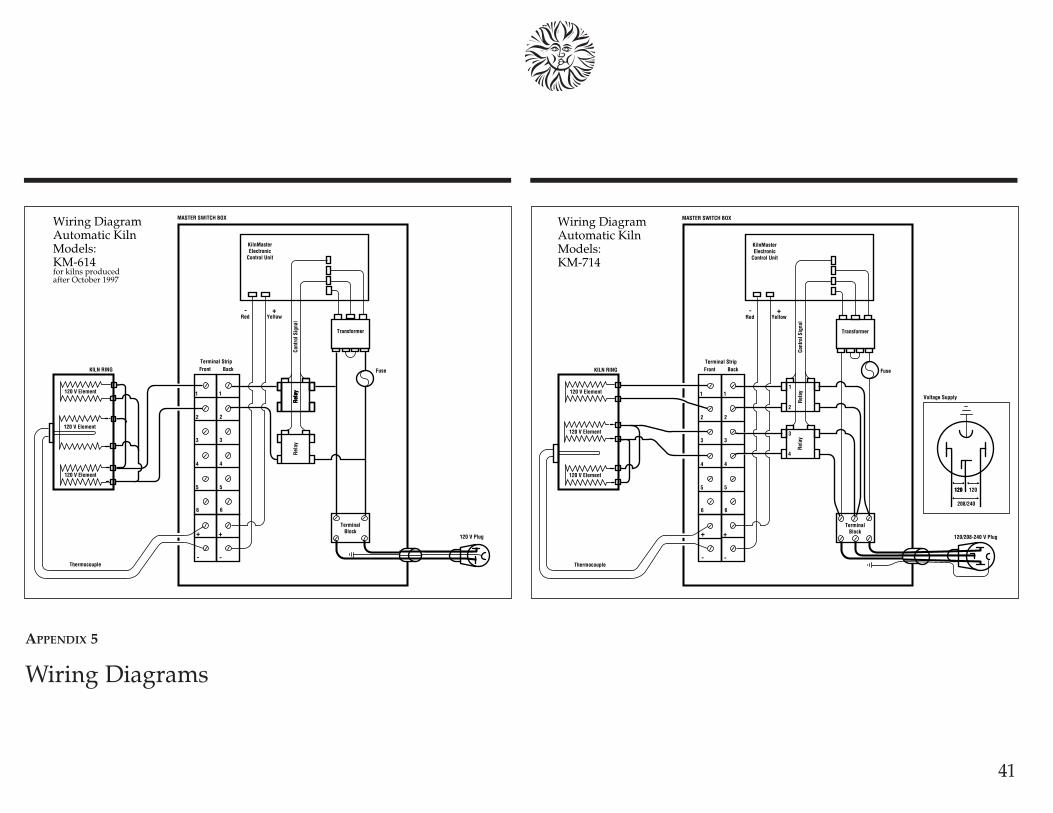
41
120 V Plug
MASTER SWITCH BOX
Transformer
Rel
ayR
elay
Rel
ayR
elay
1
2
3
4
5
6
KilnMasterElectronic
Control Unit
TerminalBlock
120 V Element
120 V Element
120 V Element
KILN RING
Terminal StripFront Back
Cont
rol S
igna
l
1
2
3
4
5
6
Fuse
Wiring DiagramAutomatic KilnModels:KM-614for kilns producedafter October 1997
+
-
+
-Thermocouple
+-Red Yellow
3
4
Rel
ay
120/208-240 V Plug
MASTER SWITCH BOX
Transformer
1
2
Rel
ay1
2
3
4
5
6
KilnMasterElectronic
Control Unit
TerminalBlock
120 V Element
120 V Element
120 V Element
KILN RING
Terminal StripFront Back
Cont
rol S
igna
l
1
2
3
4
5
6
Fuse
Wiring DiagramAutomatic KilnModels:KM-714
+
-
+
-Thermocouple
+-Red Yellow
Voltage Supply
120120 120
208/240
APPENDIX 5
Wiring Diagrams

42
3
4
Rel
ay
208/240 V Plug
MASTER SWITCH BOX
Transformer
1
2
Rel
ay1
2
3
4
5
6
KilnMasterElectronic
Control Unit
TerminalBlock
208-240 V Element
208-240 V Element
208-240 V Element
208-240 V Element
TOP RING
BOTTOM RING
Terminal StripFront Back
Cont
rol S
igna
l
1
2
3
4
5
6
Fuse
Wiring DiagramAutomatic KilnModels:KM-818KM-818-30A
+
-
+
-Thermocouple
+-Red Yellow
3
4
Rel
ay
208/240 V Plug
MASTER SWITCH BOX
Transformer
1
2
Rel
ay1
2
3
4
5
6
KilnMasterElectronic
Control Unit
TerminalBlock
208-240 V Element
208-240 V Element
208-240 V Element
208-240 V Element
TOP RING
BOTTOM RING
Terminal StripFront Back
Cont
rol S
igna
l
1
2
3
4
5
6
Fuse
Wiring DiagramAutomatic KilnModels:KM-1018
+
-
+
-Thermocouple
+-Red Yellow

43
3
4
Rel
ay
208/240 V Plug
MASTER SWITCH BOX
Transformer
5
6
Rel
ay
1
2
Rel
ay1
2
3
4
5
6
KilnMasterElectronic
Control Unit
TerminalBlock
208-240 V Element
208-240 V Element
208-240 V Element
208-240 V Element
208-240 V Element
208-240 V Element
TOP RING
MIDDLE RING
BOTTOM RING
Terminal StripFront Back
Cont
rol S
igna
l
1
2
3
4
5
6
Fuse
Wiring DiagramAutomatic KilnModels:KM-1027KM-1227
+
-
+
-Thermocouple
+-Red Yellow
3
4
Rel
ay
MASTER SWITCH BOX
Transformer
5
6
Rel
ay
1
2
Rel
ay1
2
3
4
5
6
KilnMasterElectronic
Control Unit
TerminalBlock
208-240 V Element
208-240 V Element
208-240 V Element
208-240 V Element
208-240 V Element
208-240 V Element
TOP RING
MIDDLE RING
BOTTOM RING
Terminal StripFront Back
Cont
rol S
igna
l
1
2
3
4
5
6
Fuse
Wiring DiagramAutomatic KilnModels:KM-1027, 3 PhaseKM-1227, 3 Phase
+
-
+
-Thermocouple
+-Red Yellow
208/240 V 3φ Plug

44
208/240 V Plug
KilnMaster Wall Enclosure
Transformer
Pilot Relay
ElectronicControl Unit
50 Amp Contactor
Cont
rol S
igna
l
Fuse
Wiring DiagramKilnMasterControllerKM-1 Single Phase
Thermocouple
+-Red Yellow
Inserted infiring chamber.
208/240 V Receptacle
KilnMaster Wall Enclosure
Transformer
Pilot Relay
ElectronicControl Unit
40 Amp 3φ Contactor
Cont
rol S
igna
l
Fuse
Wiring DiagramKilnMasterControllerKM-1 Three Phase
Thermocouple
+-Red Yellow
Inserted infiring chamber.
208/240 V 3φ Plug
208/240 V 3φ Receptacle
3φ PilotSocket

45
APPENDIX 7
Set-up and specifications for Skutt PK production kilnsSkutt PK production kilns are heavy duty,high capacity units designed to meet theneeds of the high fire production potter,tile maker and light industrial user. Thesekilns are equipped with upgraded compo-nents and wiring that will allow them tohigh fire extremely dense loads in a rela-tively short time.The KM-1227PK is a twelve sided kilnsimilar in capacity to our KM-1227—27” deep and 9.92 cu. ft. The KM-1231PK is 31” deep and offers11.57 cu. ft. of capacity.Both PK kilns are available in single andthree phase, 240V or 208V.
FIRING
Skutt PK kilns feature our KilnMaster con-troller, so operation is identical to otherKM kilns. Even though the earlier sectionsof this manual do not refer specifically tothe PK kiln line, you may follow all theinstructions on programming and firingroutines.
KILN IMPROVEMENTS
If you are an intensive kiln user, youmight find a PK kiln to be the appropriatechoice for your next kiln purchase. Hereare some the differences from our stan-dard KM kiln line:First, PK kilns are designed to fire full,Cone 10 loads without stalling on the highend. To do so, they are equipped withindustrial gauge wiring and three types ofelements for better firing balance. Becauseof their high rating, electrical codes requirethat they be direct wired by an electrician;therefore no plug is included.Mercury displacement relays are used forlonger life and quieter operation.The hinged control box is larger, and com-pression connectors are used on the feederwires for easier element replacement.Finally, Model KM-1231PK comes with anadditional stand for bottom slab supportunder heavy loads. This extra stand is notincluded when the kiln is ordered with aSkutt EnviroVent, which provides all thesupport needed.
APPENDIX 6
Wall-Mounted KilnMasterUL Listing
The KM-1 wall-mounted KilnMaster controller is a UL-listed accessory whenused with the following Skutt UL-listed kiln models.
1227-3, 280 240 or 208 volt1227-3 240 or 208 volt 3 phase1027-3 240 or 208 volt1027-3 240 or 208 volt 3 phase1027, 231, 235 240 or 208 volt1027 240 or 208 volt 3 phase1018-3 240 or 208 volt1018, 231-18 240 or 208 volt818-3 240 or 208 volt818, 185 240 or 208 volt818P-3 240 or 208 volt818P, 181, 183 240 or 208 volt714, 145 208-240 volt

46
UNPACKING AND MOVING PK KILNS
Follow the general instructions on kiln set-up found on pages 8 and 9 of this manual.You will probably want to separate thekiln into sections when you set it up ormove it to a different location. Theseinstructions are slightly different than forstandard KM kilns.
Caution: Before disassembling any PKkiln, be sure to turn off power to the kilnby throwing the circuit breaker or remov-ing the fuse on its circuit. Do not restorepower to the kiln until it is fully reassem-ble.
Note: The mercury relays in the switchbox must be operated only with theswitch box in a normal, vertical orienta-tion.
To disassemble the kiln1 Remove the screws from the left side of the
control box and swing the control box open.
2 Remove the screws holding the feeder wiresto the two pole blocks on the heat baffle.There are three sets with two feeder wiresgoing into each set.
3 Remove the thermocouple wires from thethermocouple terminal strip on the baffle.They are attached with slide on connectorsand should be pulled straight off. Pulling atan angle can damage the connector.
4 Lift the box up and set it aside.
5 Unfasten draw pull catches and lift sectionsapart using the handles.
To reassemble PK kilns:1 Stack the sections in original sequence and
secure the draw pull catches..
2 Place the control box on its hinges.
3 Reattach the feeder wires to their correspond-ing block. Make sure the connection is verytight to avoid electrical problems.
4 Reattach the thermocouple wires making surethat the red wire (-) is secured to the red taband the yellow wire is connected to the silvertab (+). On single zone kilns there will onlybe one set of thermocouples and they shouldbe attached to the center group of tabs.
5 Reattach the screws which secure the controlbox to the kiln jacket.

47
CONNECTING PK KILNS
As mentioned earlier, PK kilns must bedirect wired or “hard wired” into yourstudio electric system by a qualified elec-trician. Flat and Phillips screwdrivers arethe only tools required. At the time of connection, your electricianshould also check your electric wiringwhich supplies the kiln, to be sure that thecopper wire size and breaker size are ade-quate for your PK kiln electrical require-ments as shown in the table at right.
Electrical requirements for Skutt PK Production KilnsModel Volts Amps Watts Max. Cone Copper Wire Fuse or
Size* Breaker Size
KM-1231PK 240 72 17300 10 2 90KM-1231PK 208 80 16640 10 2 100KM-1231PK-3ph 240 44.5 17300 10 6 60KM-1231PK-3ph 208 51.5 17300 10 6 60KM-1227PK 240 60 14300 10 4 80KM-1227PK 208 69 14300 10 2 90KM-1227PK-3ph 240 40 14300 10 6 50KM-1227PK-3ph 208 46.7 14300 10 6 60
*An electrician will need to make the electrical connection. The kilns are “hard wired” toallow for greater amperage. For each additional 50 feet use heavier wire, numerically two numberslower—for example, instead of #6, use #4. If you anticipate installing any larger kiln in the future,use the heavier wire.
PK KILN ELEMENTS
To achieve optimum heat distribution,there are three types of elements in theproduction kilns : Top/Bottom,Intermediate, and Center. The tablesbelow show the proper placement andtype when replacing elements.
KM-1227PKSection Element Position
Upper Top/Bottom 1Intermediate 2
Master Center 3Center 4
Lower Intermediate 5Top/Bottom 6
KM-1231PKSection Element Position
Upper Top/Bottom 1Intermediate 2
Master Center 3Center 4Center 5
Lower Intermediate 6Top/Bottom 7

48
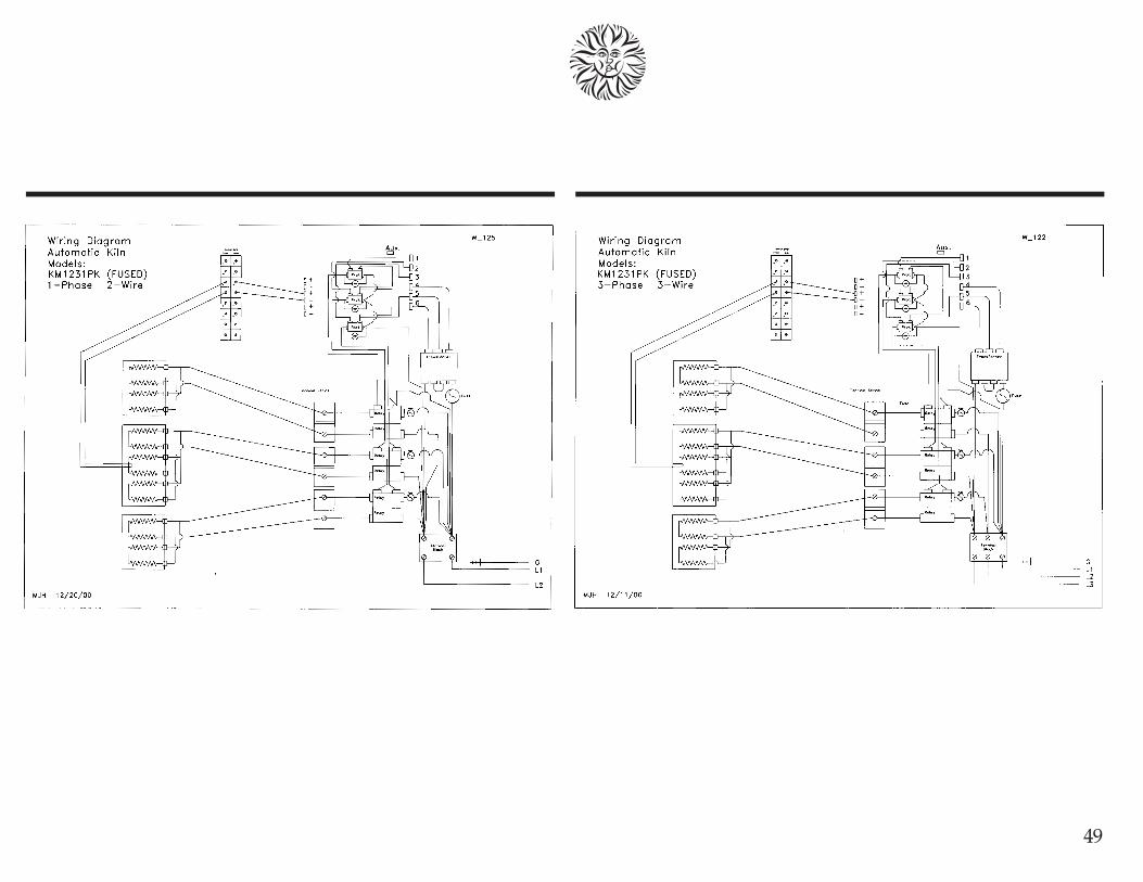
49

IndexAftercrazing .................................................... 35Alarm............................................... 2, 22, 24, 28
ALAr......................................... 22, 24, 28, 39Bisque ..............................................................35Brick repairs.................................................... 34Candling ................................................... 26, 35Ceramic ........................................................... 35Clean-up ......................................................... 35Clear display .................................................. 31Clicking .......................................................... 11Complete
CPLt ............................................... 22, 24, 39Cone
ConE .............................................. 21, 38, 39deformation .............................................. 37heat work .................................................. 38value .......................................................... 29
Cone Fire .............................................. 1, 19, 31description .................................................. 1profiles ...................................... 1, 19, 20, 21programming ..................................... 21, 22
Cone plaque ................................................... 35Cone Table ........................................... 4, 29, 38Cones .............................................................. 12
self-supporting ......................................... 12senior ......................................................... 12
Controlled cooling ........................................ 26Controller ......................................................... 4
connecting3 phase ............................................... 6, 10single phase ............................................. 6
kiln settings ................................................. 7Kiln-Sitter ................................................. 7switches .................................................... 7timer ......................................................... 7
locating ......................................................... 6mounting...................................................... 6
Crackle glaze .................................................. 35Cracks in the body......................................... 33Crazing ..................................................... 33, 35
delayed or aftercrazing ........................... 33Crystalline glaze ........................................... 27Delay ................................................... 22, 25, 28
deLA ........................................ 21, 22, 24, 39Dipping .......................................................... 35Display dim ................................................... 32Dry footing ............................................... 14, 35Electrical
chart of specifications......................... 10, 473 phase.................................................... 6, 10voltage ....................................................... 10
Element groove......................................................... 35replacing .................................................... 35
EnviroVent ..................................................... 16Error
Err ............................................................... 39messages ................................................... 40
FAIL ................................................................ 39Firebrick ......................................................... 35Firing ........................................................ 16, 35
after the firing............................................ 16china paint ................................................ 16during the firing ...................................... 18glass ............................................... 14, 18, 27glaze ............................................... 14, 16, 27greenglaze ................................................. 16lusters ........................................................ 17metallics .................................................... 16overglaze ............................................. 14, 16oxidation ................................................... 11porcelain ............................................. 14, 17stoneware ............................................ 14, 17underglaze ................................................ 16
Floor repairs .................................................. 34Foot ................................................................. 35
Fuse, electrical ......................................... 32, 37Glass slumping .............................................. 27Glaze ................................................... 14, 18, 35
cloudy ........................................................ 33cratered or bubbled ................................. 32crawled ...................................................... 32excessive .................................................... 33grainy ......................................................... 33red
discolored .............................................. 33grayed .................................................... 33
sagging ...................................................... 32textured ..................................................... 33
Greenware ............................................... 13, 35Heat work ...................................................... 37Hold ................................................................. 24
HLD ........................................................... 39HLd 1-8 ............................................... 25, 39HOLd ................................................... 22, 39
Impurities ....................................................... 35Incising ........................................................... 35Kiln-Sitter ....................................................... 36Kiln wash ................................................. 11, 36KilnMaster controller ............................... 4, 35
features ........................................ 1, 4, 19, 37wall mount
repairs ...................................................... 7Lid repairs...................................................... 34Limit timer ..................................................... 36Loading .................................................... 13, 15
glass fusing ............................................... 14glaze ........................................................... 14greenware ................................................. 13overglaze ................................................... 13porcelain .................................................... 13
Locating kiln .....................................................8Lusters ...................................................... 17, 36Mature ............................................................ 36Multitester ...................................................... 36Nesting ........................................................... 36
50

Ohm meter ..................................................... 36One-fire .......................................................... 36Overglaze ................................................. 16, 36
discolored .................................................. 33PK Production Kilns...................................... 45Peephole ................................................... 15, 36Peephole plug .......................................... 15, 36Pinholes .................................................... 32, 36Porcelain ............................................ 17, 27, 36Posts, ............................................................... 36Pouring, ........................................................... 36Power failure, PF .............................. 22, 25, 39Pyrometer ....................................................... 36Pyrometric Cone ............................... 12, 36, 38Ramp/Hold ............................. 1, 26, 31, 37, 38
description ................................................ 24hold ...................................................... 24, 39programming ..................................... 25, 26rate ............................................................. 24temperature .............................................. 24
RaterA ............................................................... 39rA 1-6 ......................................................... 25
Refractory ....................................................... 36Repairs ............................................................ 34
Wall repairs .............................................. 34Floor repairs ............................................. 34Lid repairs ................................................. 34KilnMaster repairs ..................................... 7
Replacing elements ....................................... 35Replacing thermocouple ...................... 7, 8, 35Review ............................................................ 29Segment .................................................... 24. 29
chart ..................................................... 24, 29SEGS .................................................... 23, 39
Sgraffito .......................................................... 36Shelf .......................................................... 10, 36Shiny matte surface ...................................... 33Shut off
early ........................................................... 31
Slip .................................................................. 36Soaking ........................................................... 36Specifications
fuse ............................................................. 37Speed
SPd ....................................................... 22, 39Stilts .......................................................... 14, 36Start firing ....................................................... 30Stoneware ................................................ 17, 36Stop firing ...................................................... 30Talc .................................................................. 36Temperature
flashing ............................................ 1, 30, 39scale selector ............................................. 28steady ......................................................... 39
Terminal brick ............................................... 36Terra cotta ...................................................... 36Thermocouple .....................................7, 36, 37
flaking ........................................................ 32mounting ..................................................... 7replacement .......................................... 7, 35
Three-phaseoperation ............................................... 6, 10
Timedecreasing ................................................. 39
Troubleshooting ............................................. 31fuses ........................................................... 32
Underglaze ........................................ 16, 33, 36Unpacking kiln .......................................... 8, 46User profile ................................................ 2, 23
USEr ................................................. 2, 24, 39Venting ..................................................... 15, 36
EnviroVent .......................................... 15, 16lid ......................................................... 15, 16
View ................................................................ 29Vitreous .......................................................... 36Volt meter ...................................................... 36Ware .......................................................... 32, 36Warpage ......................................................... 36Wiring diagrams ...................................... 41, 48
51

52
7
8
5
6
4
1
2
3
HoldTemperatureRateSegment
Photocopy Masters for yourRamp/Hold User Profiles
7
8
5
6
4
1
2
3
HoldTemperatureRateSegment
7
8
5
6
4
1
2
3
HoldTemperatureRateSegment
7
8
5
6
4
1
2
3
HoldTemperatureRateSegment


Skutt Ceramic Products6441 S.E. Johnson Creek Blvd.Portland, Oregon 97206-9594Telephone (503) 774-6000 Fax (503) 774-7833