CompactLogix Controllers Specificationsanduong.vn/uploadfile/products/files/1381908012.pdf ·...
68
Technical Data CompactLogix Controllers Specifications CompactLogix 5370 Controller Catalog Numbers 1769-L16ER-BB1B, 1769-L18ER-BB1B, 1769-L18ERM-BB1B, 1769-L24ER-QB1B, 1769-L24ER-QBFC1B, 1769-L27ERM-QBFC1B,1769-L30ER, 1769-L30ER-NSE, 1769-L30ERM, 1769-L33ER, 1769-L33ERM, 1769-L36ERM 1769 Packaged Controller Catalog Numbers 1769-L23-QBFC1B, 1769-L23E-QB1B, 1769-L23E-QBFC1B 1769 Modular Controller Catalog Numbers 1769-L31, 1769-L32C, 1769-L35CR, 1769-L32E, 1769-L35E 1768 Controller Catalog Numbers 1768-L43, 1768-L43S, 1768-L45, 1768-L45S Memory Card Catalog Numbers 1784-CF128, 1784-SD1, 1784-SD2 Topic Page CompactLogix 5370 Controllers 4 1769 Packaged CompactLogix Controllers with Embedded I/O 34 1769 Modular CompactLogix Controllers 45 1768 CompactLogix Controllers 49 Controller Memory Use 56 Controller Compatibility 57 Controller Connections 60 Determine Total Connection Use 62 CompactLogix Controller Accessories 63
Transcript of CompactLogix Controllers Specificationsanduong.vn/uploadfile/products/files/1381908012.pdf ·...

Technical Data
CompactLogix Controllers SpecificationsCompactLogix 5370 Controller Catalog Numbers 1769-L16ER-BB1B, 1769-L18ER-BB1B, 1769-L18ERM-BB1B, 1769-L24ER-QB1B, 1769-L24ER-QBFC1B, 1769-L27ERM-QBFC1B,1769-L30ER, 1769-L30ER-NSE, 1769-L30ERM, 1769-L33ER, 1769-L33ERM, 1769-L36ERM
1769 Packaged Controller Catalog Numbers1769-L23-QBFC1B, 1769-L23E-QB1B, 1769-L23E-QBFC1B
1769 Modular Controller Catalog Numbers 1769-L31, 1769-L32C, 1769-L35CR, 1769-L32E, 1769-L35E
1768 Controller Catalog Numbers 1768-L43, 1768-L43S, 1768-L45, 1768-L45S
Memory Card Catalog Numbers1784-CF128, 1784-SD1, 1784-SD2
Topic Page
CompactLogix 5370 Controllers 4
1769 Packaged CompactLogix Controllers with Embedded I/O 34
1769 Modular CompactLogix Controllers 45
1768 CompactLogix Controllers 49
Controller Memory Use 56
Controller Compatibility 57
Controller Connections 60
Determine Total Connection Use 62
CompactLogix Controller Accessories 63
CompactLogix Controllers Specifications
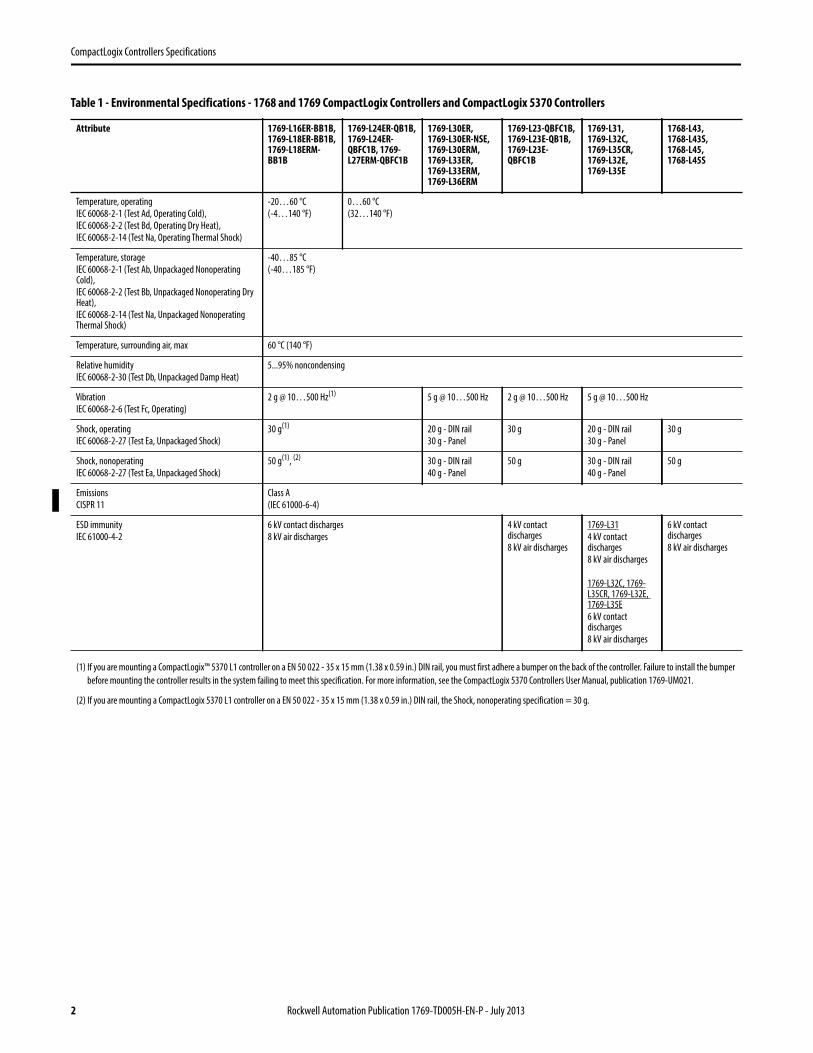
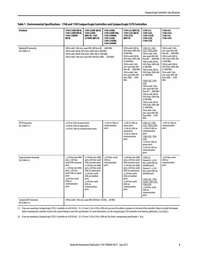
Table 1 - Environmental Specifications - 1768 and 1769 CompactLogix Controllers and CompactLogix 5370 Controllers
Attribute 1769-L16ER-BB1B, 1769-L18ER-BB1B, 1769-L18ERM-BB1B
1769-L24ER-QB1B, 1769-L24ER-QBFC1B, 1769-L27ERM-QBFC1B
1769-L30ER, 1769-L30ER-NSE, 1769-L30ERM, 1769-L33ER, 1769-L33ERM, 1769-L36ERM
1769-L23-QBFC1B, 1769-L23E-QB1B, 1769-L23E-QBFC1B
1769-L31, 1769-L32C, 1769-L35CR, 1769-L32E, 1769-L35E
1768-L43, 1768-L43S, 1768-L45, 1768-L45S
Temperature, operating
IEC 60068-2-1 (Test Ad, Operating Cold),
IEC 60068-2-2 (Test Bd, Operating Dry Heat),
IEC 60068-2-14 (Test Na, Operating Thermal Shock)
-20…60 °C
(-4…140 °F)
0…60 °C
(32…140 °F)
Temperature, storage
IEC 60068-2-1 (Test Ab, Unpackaged Nonoperating Cold),
IEC 60068-2-2 (Test Bb, Unpackaged Nonoperating Dry Heat),
IEC 60068-2-14 (Test Na, Unpackaged Nonoperating Thermal Shock)
-40…85 °C
(-40…185 °F)
Temperature, surrounding air, max 60 °C (140 °F)
Relative humidity
IEC 60068-2-30 (Test Db, Unpackaged Damp Heat)
5...95% noncondensing
Vibration
IEC 60068-2-6 (Test Fc, Operating)
2 g @ 10…500 Hz(1) 5 g @ 10…500 Hz 2 g @ 10…500 Hz 5 g @ 10…500 Hz
Shock, operating
IEC 60068-2-27 (Test Ea, Unpackaged Shock)
30 g(1) 20 g - DIN rail
30 g - Panel
30 g 20 g - DIN rail
30 g - Panel
30 g
Shock, nonoperating
IEC 60068-2-27 (Test Ea, Unpackaged Shock)
50 g(1), (2) 30 g - DIN rail
40 g - Panel
50 g 30 g - DIN rail
40 g - Panel
50 g
Emissions
CISPR 11
Class A
(IEC 61000-6-4)
ESD immunity
IEC 61000-4-2
6 kV contact discharges
8 kV air discharges
4 kV contact discharges
8 kV air discharges
1769-L31
4 kV contact discharges
8 kV air discharges
1769-L32C, 1769-L35CR, 1769-L32E, 1769-L35E
6 kV contact discharges
8 kV air discharges
6 kV contact discharges
8 kV air discharges
(1) If you are mounting a CompactLogix™ 5370 L1 controller on a EN 50 022 - 35 x 15 mm (1.38 x 0.59 in.) DIN rail, you must first adhere a bumper on the back of the controller. Failure to install the bumper
before mounting the controller results in the system failing to meet this specification. For more information, see the CompactLogix 5370 Controllers User Manual, publication 1769-UM021.
(2) If you are mounting a CompactLogix 5370 L1 controller on a EN 50 022 - 35 x 15 mm (1.38 x 0.59 in.) DIN rail, the Shock, nonoperating specification = 30 g.
2 Rockwell Automation Publication 1769-TD005H-EN-P - July 2013
CompactLogix Controllers Specifications
Radiated RF immunity
IEC 61000-4-3
10V/m with 1 kHz sine-wave 80% AM from 80…2000 MHz
10V/m with 200 Hz 50% Pulse 100% AM @ 900 MHz
10V/m with 200 Hz 50% Pulse 100% AM @ 1890 MHz
10V/m with 1 kHz sine-wave 80% AM from 2000…2700 MHz
10V/m with 200 Hz 50% Pulse 100% AM at 900 MHz
10V/m with 200 Hz 50% Pulse 100% AM at 1890 MHz
10V/m with 1 kHz sine-wave 80% AM from 80…2000 MHz
10V/m with 1 kHz sine-wave 80% AM from 2000…2700 MHz
1769-L31, 1769-L32C, 1769-L35CR
10V/m with 1 kHz sine-wave 80% AM from 80…2000 MHz
10V/m with 200 Hz 50% Pulse 100% AM @ 900 MHz
10V/m with 200 Hz 50% Pulse 100% AM @ 1890 MHz
1769-L32E, 1769-L35E
10V/m with 1 kHz sine-wave 80% AM from 80…2000 MHz
10V/m with 200 Hz 50% Pulse 100% AM @ 900 MHz
10V/m with 200 Hz 50% Pulse 100% AM @ 1890 MHz
3V/m with 1 kHz sine-wave 80% AM from 2000…2700 MHz
10V/m with 1 kHz sine-wave 80% AM from 80…2000 MHz
10V/m with 200 Hz 50% Pulse 100% AM @ 900 MHz
10V/m with 200 Hz 50% Pulse 100% AM @ 1890 MHz
3V/m with 1 kHz sine-wave 80% AM from 2000…2700 MHz
EFT/B immunity
IEC 61000-4-4
±3 kV at 5 kHz on power ports
±3 kV at 5 kHz on signal ports
±3 kV at 5 kHz on communication ports
±3 kV at 5 kHz on communication ports
±2 kV at 5 kHz on power ports
±2 kV at 5 kHz on signal ports
±2 kV at 5 kHz on communication ports
1769-L31, 1769-L32C, 1769-L35CR
±2 kV at 5 kHz on communication ports
1769-L32E, 1769-L35E
±3 kV at 5 kHz on power ports
±3 kV at 5 kHz on communication ports
±4 kV at 5 kHz on communication ports
Surge transient immunity
IEC 61000-4-5
+ 1 kV line-line (DM) and + 2 kV line-earth (CM) on power ports
+ 1 kV line-line (DM) and + 2 kV line-earth (CM) on signal ports
+2 kV line-earth (CM) on communication ports
±1 kV line-line (DM) and +2 kV line-earth (CM) on power ports
±1 kV line-line (DM) and +2 kV line-earth (CM) on signal ports
+2 kV line-earth (CM) on shielded ports
±2 kV line-earth (CM) on communication ports
±2 kV line-earth (CM) on communication ports
±1 kV line-line (DM) and +2 kV line-earth (CM) on power ports
±1 kV line-line (DM) and +2 kV line-earth (CM) on signal ports
+2 kV line-earth (CM) on shielded ports
±2 kV line-earth (CM) on communication ports
1769-L31
Channel 0: ±2 kV line-earth (CM) on shielded ports
Channel 1: ±1 kV line-earth (CM) on shielded ports
1769-L32C, 1769-L35CR, 1769-L32E, 1769-L35E
±2 kV line-earth (CM) on communication ports
±2 kV line-earth (CM) on communication ports
Conducted RF immunity
IEC 61000-4-6
10Vrms with 1 kHz sine-wave 80% AM from 150 kHz…80 MHz
(1) If you are mounting a CompactLogix 5370 L1 controller on a EN 50 022 - 35 x 15 mm (1.38 x 0.59 in.) DIN rail, you must first adhere a bumper on the back of the controller. Failure to install the bumper
before mounting the controller results in the system failing to meet this specification. For more information, see the CompactLogix 5370 Controllers User Manual, publication 1769-UM021.
(2) If you are mounting a CompactLogix 5370 L1 controller on a EN 50 022 - 35 x 15 mm (1.38 x 0.59 in.) DIN rail, the Shock, nonoperating specification = 30 g.
Table 1 - Environmental Specifications - 1768 and 1769 CompactLogix Controllers and CompactLogix 5370 Controllers
Attribute 1769-L16ER-BB1B, 1769-L18ER-BB1B, 1769-L18ERM-BB1B
1769-L24ER-QB1B, 1769-L24ER-QBFC1B, 1769-L27ERM-QBFC1B
1769-L30ER, 1769-L30ER-NSE, 1769-L30ERM, 1769-L33ER, 1769-L33ERM, 1769-L36ERM
1769-L23-QBFC1B, 1769-L23E-QB1B, 1769-L23E-QBFC1B
1769-L31, 1769-L32C, 1769-L35CR, 1769-L32E, 1769-L35E
1768-L43, 1768-L43S, 1768-L45, 1768-L45S
Rockwell Automation Publication 1769-TD005H-EN-P - July 2013 3
CompactLogix Controllers Specifications
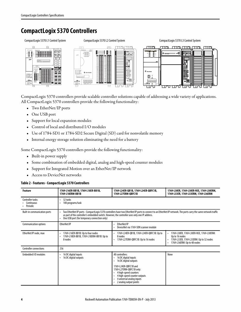
CompactLogix 5370 Controllers
CompactLogix 5370 controllers provide scalable controller solutions capable of addressing a wide variety of applications. All CompactLogix 5370 controllers provide the following functionality:
• Two EtherNet/IP ports• One USB port• Support for local expansion modules• Control of local and distributed I/O modules• Use of 1784-SD1 or 1784-SD2 Secure Digital (SD) card for nonvolatile memory• Internal energy storage solution eliminating the need for a battery
Some CompactLogix 5370 controllers provide the following functionality:• Built-in power supply• Some combination of embedded digital, analog and high-speed counter modules• Support for Integrated Motion over an EtherNet/IP network• Access to DeviceNet networks
Table 2 - Features - CompactLogix 5370 Controllers
Feature 1769-L16ER-BB1B, 1769-L18ER-BB1B, 1769-L18ERM-BB1B
1769-L24ER-QB1B, 1769-L24ER-QBFC1B, 1769-L27ERM-QBFC1B
1769-L30ER, 1769-L30ER-NSE, 1769-L30ERM, 1769-L33ER, 1769-L33ERM, 1769-L36ERM
Controller tasks:• Continuous• Periodic
• 32 tasks• 100 programs/task
Built-in communication ports • Two EtherNet/IP ports - CompactLogix 5370 controllers have two EtherNet/IP ports to connect to an EtherNet/IP network. The ports carry the same network traffic as part of the controller’s embedded switch. However, the controller uses only one IP address.
• One USB port (for temporary connection only)
Communication options EtherNet/IP • EtherNet/IP• DeviceNet via 1769-SDN scanner module
EtherNet/IP node, max • 1769-L16ER-BB1B: Up to four nodes• 1769-L18ER-BB1B, 1769-L18ERM-BB1B: Up to
8 nodes
• 1769-L24ER-QB1B, 1769-L24ER-QBFC1B: Up to 8 nodes
• 1769-L27ERM-QBFC1B: Up to 16 nodes
• 1769-L30ER, 1769-L30ER-NSE, 1769-L30ERM: Up to 16 nodes
• 1769-L33ER, 1769-L33ERM: Up to 32 nodes• 1769-L36ERM: Up to 48 nodes
Controller connections 256
Embedded I/O modules • 16 DC digital inputs• 16 DC digital outputs
All controllers:• 16 DC digital inputs• 16 DC digital outputs
1769-L24ER-QBFC1B and 1769-L27ERM-QBFC1B only:• 4 high-speed counters• 4 high-speed counter outputs• 4 universal analog inputs• 2 analog output points
None
2 (Rear)
00:00:BC:2E:69:F61 (Front)
0 1 2 3 4 5 6 7
8 9 10 11 12 13 14 15
0 1 2 3 4 5 6 7
8 9 10
A0 B0 Z0
A1 B1 Z1
0 2 FUSE
1 3 OK11 12 13 14 15
HIG
H S
PEED
COU
NTE
R
INO
UT
DC
INPU
T
24VD
CSI
NK\
SOU
RCE
24VD
CSO
URC
E
OU
TPU
TD
C
+24VDC COM FG
0 1 2 3 4 5 6 7
8 9 10 11 12 13 14 15
0 1 2 3 4 5 6 7
8 9 10
A0 B0 Z0
A1 B1 Z1
0 2 FUSE
1 3 OK11 12 13 14 15
HIG
H S
PEED
COU
NTE
R
INO
UT
DC
INPU
T
24VD
CSI
NK\
SOU
RCE
24VD
CSO
URC
E
OU
TPU
TD
C
+24VDC COM FG
00
01
02
03
04
05
06
07
NC
+V
00
01
02
03
04
05
06
07
COM0
COM0
08
09
10
11
12
13
14
15
NC
+V
08
09
10
11
12
13
14
15
COM1
COM1
A0+
B0+
Z0+
A1+
B1+
Z1+
+V
OUT1
OUT0
COM COM
A0-
B0-
Z0-
A1-
B1-
Z1-
+V
0UT3
Vin0+
Vin2+
VOUT0+I
OUT0+
VOUT1+
Iin3+
Vin1+Iin1+
Iin1+
Vin3+
CJC-
CJC+
V/Iin1-
V/Iin3-
V/Iin0-
V/Iin2-
Iin0+
Iin2+
OUT2
COMCOM
DC IN HSC
DC OUT ANALOG
00:00:BC:2E:69:F6
L27ERM
QBFC1B
CompactLogix 5370 L1 Control System CompactLogix 5370 L3 Control SystemCompactLogix 5370 L2 Control System
4 Rockwell Automation Publication 1769-TD005H-EN-P - July 2013
CompactLogix Controllers Specifications
Sockets, max 32
Integrated Motion over an EtherNet/IP network
1769-L18ERM-BB1B - 1 or 2 axes 1769-L27ERM-QBFC1B - As many as 4 axes • 1769-L30ERM - As many as 4 axes• 1769-L33ERM - As many as 8 axes• 1769-L36ERM - As many as 16 axes
Programming languages • Relay ladder• Structured text• Function block• SFC
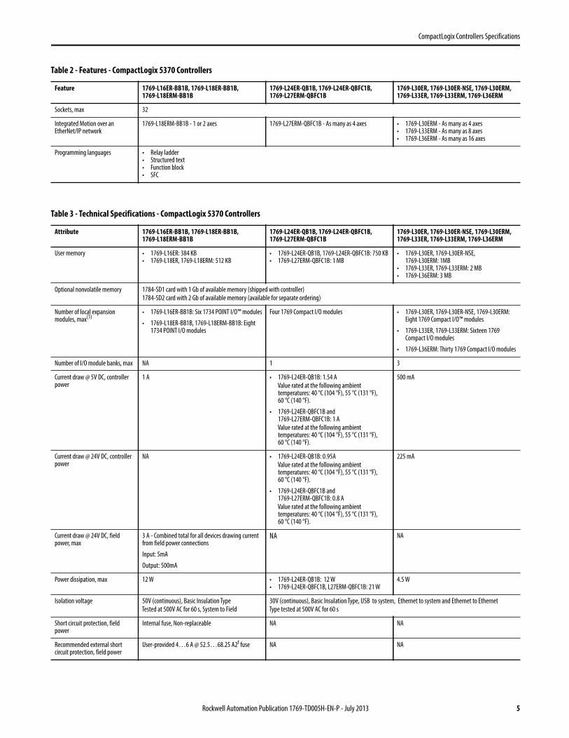
Table 3 - Technical Specifications - CompactLogix 5370 Controllers
Attribute 1769-L16ER-BB1B, 1769-L18ER-BB1B, 1769-L18ERM-BB1B
1769-L24ER-QB1B, 1769-L24ER-QBFC1B, 1769-L27ERM-QBFC1B
1769-L30ER, 1769-L30ER-NSE, 1769-L30ERM, 1769-L33ER, 1769-L33ERM, 1769-L36ERM
User memory • 1769-L16ER: 384 KB• 1769-L18ER, 1769-L18ERM: 512 KB
• 1769-L24ER-QB1B, 1769-L24ER-QBFC1B: 750 KB• 1769-L27ERM-QBFC1B: 1 MB
• 1769-L30ER, 1769-L30ER-NSE, 1769-L30ERM: 1MB
• 1769-L33ER, 1769-L33ERM: 2 MB• 1769-L36ERM: 3 MB
Optional nonvolatile memory 1784-SD1 card with 1 Gb of available memory (shipped with controller)
1784-SD2 card with 2 Gb of available memory (available for separate ordering)
Number of local expansion modules, max(1)
• 1769-L16ER-BB1B: Six 1734 POINT I/O™ modules
• 1769-L18ER-BB1B, 1769-L18ERM-BB1B: Eight 1734 POINT I/O modules
Four 1769 Compact I/O modules • 1769-L30ER, 1769-L30ER-NSE, 1769-L30ERM: Eight 1769 Compact I/O™ modules
• 1769-L33ER, 1769-L33ERM: Sixteen 1769 Compact I/O modules
• 1769-L36ERM: Thirty 1769 Compact I/O modules
Number of I/O module banks, max NA 1 3
Current draw @ 5V DC, controller power
1 A • 1769-L24ER-QB1B: 1.54 A
Value rated at the following ambient temperatures: 40 °C (104 °F), 55 °C (131 °F), 60 °C (140 °F).
• 1769-L24ER-QBFC1B and 1769-L27ERM-QBFC1B: 1 A
Value rated at the following ambient temperatures: 40 °C (104 °F), 55 °C (131 °F), 60 °C (140 °F).
500 mA
Current draw @ 24V DC, controller power
NA • 1769-L24ER-QB1B: 0.95A
Value rated at the following ambient temperatures: 40 °C (104 °F), 55 °C (131 °F), 60 °C (140 °F).
• 1769-L24ER-QBFC1B and 1769-L27ERM-QBFC1B: 0.8 A
Value rated at the following ambient temperatures: 40 °C (104 °F), 55 °C (131 °F), 60 °C (140 °F).
225 mA
Current draw @ 24V DC, field power, max
3 A - Combined total for all devices drawing current from field power connections
Input: 5mA
Output: 500mA
NA NA
Power dissipation, max 12 W • 1769-L24ER-QB1B: 12 W• 1769-L24ER-QBFC1B, L27ERM-QBFC1B: 21 W
4.5 W
Isolation voltage 50V (continuous), Basic Insulation Type
Tested at 500V AC for 60 s, System to Field
30V (continuous), Basic Insulation Type, USB to system, Ethernet to system and Ethernet to Ethernet
Type tested at 500V AC for 60 s
Short circuit protection, field power
Internal fuse, Non-replaceable NA NA
Recommended external short circuit protection, field power
User-provided 4…6 A @ 52.5…68.25 A2t fuse NA NA
Table 2 - Features - CompactLogix 5370 Controllers
Feature 1769-L16ER-BB1B, 1769-L18ER-BB1B, 1769-L18ERM-BB1B
1769-L24ER-QB1B, 1769-L24ER-QBFC1B, 1769-L27ERM-QBFC1B
1769-L30ER, 1769-L30ER-NSE, 1769-L30ERM, 1769-L33ER, 1769-L33ERM, 1769-L36ERM
Rockwell Automation Publication 1769-TD005H-EN-P - July 2013 5
CompactLogix Controllers Specifications
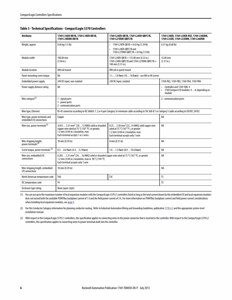
Weight, approx 0.66 kg (1.5 lb) • 1769-L24ER-QB1B = 0.63 kg (1.39 lb)
• 1769-L24ER-QBFC1B and 1769-L27ERM-QBFC1B = 0.9 kg (1.9 lb)
0.31 kg (0.68 lb)
Module width 100.00 mm
(3.94 in.)
1769-L24ER-QB1B = 115.00 mm (4.53 in.)
1769-L24ER-QBFC1B and 1769-L27ERM-QBFC1B = 140 mm (5.51 in.)
55.00 mm
(2.17 in.)
Module location DIN rail mount DIN rail or panel mount
Panel-mounting screw torque NA 1.1…1.8 Nm (10…16 lbin) - use M4 or #8 screws
Embedded power supply 24V DC input, non-isolated 24V DC Input, isolated 1769-PA2, 1769-PB2, 1769-PA4, 1769-PB4
Power supply distance rating NA • Controller and 1769-SDN: 4• 1769 Compact I/O modules: 4…8, depending on
module
Wire category(2) 1 - signal ports
1 - power ports
2 - communication ports
2 - communication ports
Wire type, Ethernet RJ-45 connector according to IEC 60603-7, 2 or 4 pair Category 5e minimum cable according to TIA 568-B.1 or Category 5 cable according to ISO/IEC 24702
Wire type, power terminals and embedded I/O connections
Copper NA
Wire size, power terminals(3) 0.051…3.31 mm2 (30…12 AWG) solid or stranded copper wire rated at 75 °C (167 °F), or greater,1.2 mm (3/64 in.) insulation, max
Each terminal accepts 1 or 2 wires
0.25…2.50 mm2 (22...14 AWG) solid copper wire rated at 75 °C (167 °F ), or greater
1.2 mm (3/64 in.) insulation, max
Each terminal accepts only 1 wire
NA
Wire stripping length, power terminals(3)
10 mm (0.39 in) 8 mm (0.31 in) NA
Screw torque, power terminals (3) 0.5…0.6 Nm (4.4…5.3 lbin) 1.0…1.2 Nm (8.9…10.6 lbin) NA
Wire size, embedded I/O connections
0.205…1.31 mm2 (24…16 AWG) solid or stranded copper wire rated at 75 °C (167 °F), or greater
1.2 mm (3/64 in.) insulation, max or 90 °C (194 °F)
Each terminal accepts only 1 wire
NA
Wire stripping length, embeddedI/O connections
10 mm (0.39 in) NA
North American temperature code T4A T3C T5
IEC temperature code T4 T5
Enclosure type rating None (open-style)
(1) You can use up to the maximum number of local expansion modules with the CompactLogix 5370 L1 controllers listed as long as the total current drawn by the embedded I/O and local expansion modules
does not exceed both the available POINTBus backplane current of 1 A and the field power current of 3 A. For more information on POINTBus backplane current and field power current considerations
when installing local expansion modules, see page 9.
(2) Use this Conductor Category information for planning conductor routing. Refer to Industrial Automation Wiring and Grounding Guidelines, publication 1770-4.1 and the appropriate system-level
installation manual.
(3) With respect to the CompactLogix 5370 L1 controllers, this specification applies to connecting wires to the power connector that is inserted in the controller. With respect to the CompactLogix 5370 L2
controllers, this specification applies to connecting wires to power terminals built into the controller.
Table 3 - Technical Specifications - CompactLogix 5370 Controllers
Attribute 1769-L16ER-BB1B, 1769-L18ER-BB1B, 1769-L18ERM-BB1B
1769-L24ER-QB1B, 1769-L24ER-QBFC1B, 1769-L27ERM-QBFC1B
1769-L30ER, 1769-L30ER-NSE, 1769-L30ERM, 1769-L33ER, 1769-L33ERM, 1769-L36ERM
6 Rockwell Automation Publication 1769-TD005H-EN-P - July 2013
CompactLogix Controllers Specifications
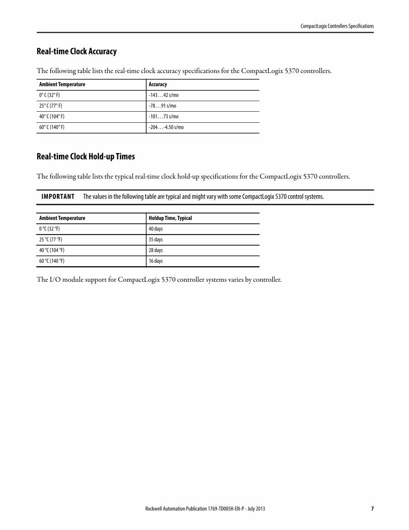
Real-time Clock Accuracy
The following table lists the real-time clock accuracy specifications for the CompactLogix 5370 controllers.
Real-time Clock Hold-up Times
The following table lists the typical real-time clock hold-up specifications for the CompactLogix 5370 controllers.
The I/O module support for CompactLogix 5370 controller systems varies by controller.
Ambient Temperature Accuracy
0° C (32° F) -143…42 s/mo
25° C (77° F) -78…91 s/mo
40° C (104° F) -101…73 s/mo
60° C (140° F) -204…-4.50 s/mo
IMPORTANT The values in the following table are typical and might vary with some CompactLogix 5370 control systems.
Ambient Temperature Holdup Time, Typical
0 °C (32 °F) 40 days
25 °C (77 °F) 35 days
40 °C (104 °F) 28 days
60 °C (140 °F) 16 days
Rockwell Automation Publication 1769-TD005H-EN-P - July 2013 7
CompactLogix Controllers Specifications
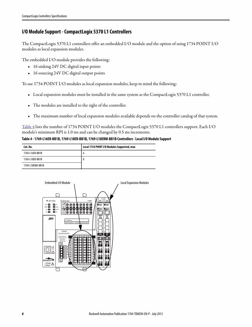
I/O Module Support - CompactLogix 5370 L1 Controllers
The CompactLogix 5370 L1 controllers offer an embedded I/O module and the option of using 1734 POINT I/O modules as local expansion modules.
The embedded I/O module provides the following:• 16 sinking 24V DC digital input points• 16 sourcing 24V DC digital output points
To use 1734 POINT I/O modules as local expansion modules, keep in mind the following:
• Local expansion modules must be installed in the same system as the CompactLogix 5370 L1 controller.
• The modules are installed to the right of the controller.
• The maximum number of local expansion modules available depends on the controller catalog of that system.
Table 4 lists the number of 1734 POINT I/O modules the CompactLogix 5370 L1 controllers support. Each I/O module’s minimum RPI is 1.0 ms and can be changed by 0.5 ms increments.Table 4 - 1769-L16ER-BB1B, 1769-L18ER-BB1B, 1769-L18ERM-BB1B Controllers - Local I/O Module Support
Cat. No. Local 1734 POINT I/O Modules Supported, max
1769-L16ER-BB1B 6
1769-L18ER-BB1B 8
1769-L18ERM-BB1B
Local Expansion ModulesEmbedded I/O Module
8 Rockwell Automation Publication 1769-TD005H-EN-P - July 2013
CompactLogix Controllers Specifications
You can use up to the maximum number of 1734 POINT I/O modules with the CompactLogix 5370 L1 controllers listed in Table 4, as long as the total current drawn by the embedded I/O and local expansion modules does not exceed both the available POINTBus backplane current of 1 A and the field power current of 3 A.
Depending on your application’s configuration, you can use one of the following devices to make additional POINTBus backplane current and/or field power current available:
• 1734-EP24DC POINT I/O Expansion Power Supply - An expansion power supply is installed between embedded I/O modules and local expansion modules or between local expansion modules.
The expansion power supply breaks the available POINTBus backplane current between the modules to its left and right. With the expansion power supply installed, the modules to its left can draw up to 1 A of POINTBus backplane current and the modules to its right can draw as much current as that provided by the expansion power supply.
Additionally, the expansion power supply breaks the available field power current between the modules to its left and right With the expansion power supply installed, the modules to its left can draw up to 3 A of field power current and the modules to its right can draw as much field power current as allowed by the expansion power supply.
For more information on the 1734-EP24DC expansion power supply, see the POINT I/O 24V DC Expansion Power Supply Installation Instructions, publication 1734-IN058.
• 1734-FPD POINT I/O Field Power Distributor Module - A field power distributor module can also be installed between embedded I/O modules and local expansion modules or between local expansion modules.
The field power distributor module breaks the available field power current between the modules to its left and right. With the field power distributor module installed, the modules to its left can draw up 3 A of field power current, and the modules to its right can draw as much field power current as allowed by the field power distributor.
For more information on the 1734-FPD POINT I/O Field Power Distributor module, see the POINT I/O Field Power Distributor Module Installation Instructions, publication 1734-IN059.
IMPORTANT Remember, the field power distributor module changes only the level of field power current available in the system. It
does not affect the level of POINTBus backplane current available.
Rockwell Automation Publication 1769-TD005H-EN-P - July 2013 9
CompactLogix Controllers Specifications
CompactLogix 5370 L1 Controllers’ Local I/O Performance
The requested packet interval (RPI) defines the frequency at which the controller sends data to and receives data from I/O modules. You set an RPI rate for each I/O module in your system.
CompactLogix 5370 L1 controllers always attempt to scan an I/O module at the configured RPI rate. For individual I/O modules, a Module RPI Overlap minor fault occurs if there are enough I/O modules with RPI rates set too fast that they cannot all be serviced in the allotted interval.
The specific configuration parameters for a system determine the impact on actual RPI rates. These configuration factors can impact the effective scan frequency for any individual module:
• Rates at which other 1734 POINT I/O modules’ RPI rates are set• Number of other 1734 POINT I/O modules in the system• Types of other 1734 POINT I/O modules in the system• Application user task priorities
In general, follow these guidelines when setting the RPI rates in a CompactLogix 5370 L1 control system:• For digital modules:
– 1…2 modules can be scanned in 2 ms.– 3…4 modules can be scanned in 4 ms.– 5…8 modules can be scanned in 8 ms.
• For specialty and analog modules (except 1734-485ASC modules):– 1 module can be scanned at 20 ms.– For each additional module add 20 ms.For example, if a CompactLogix 5370 L1 control system uses two analog modules, the module can be scanned in 40 ms.
• For 1734-485ASC modules, the sum total data size for all ASC modules determines the RPI rates:– For total data size less than 20 bytes, each module can be scanned in 20 ms. – For data size greater than 20 bytes, use the size value as the RPI.For example, if the total data size is 40 bytes, each ASC module can be scanned in 40 ms.
You are not required to set individual 1734 POINT I/O modules’ RPI values to the values listed above. For example, if your application scans one or two modules, you do not have to use RPI rates of 2 ms. Remember, though, that higher RPI rates result in scanning the data less frequently.
The RPI shows how quickly modules can be scanned, not how quickly an application can use the data. The RPI is asynchronous to the program scan. Other factors, such as program execution duration, affect I/O throughput.
IMPORTANT When considering digital I/O modules, remember that they can be the embedded I/O module on the controller or
1734 POINT I/O modules used as local expansion modules. Therefore, the consideration for using two modules can be the
embedded I/O module and a 1734 POINT I/O module or two 1734 POINT I/O modules.
10 Rockwell Automation Publication 1769-TD005H-EN-P - July 2013
CompactLogix Controllers Specifications
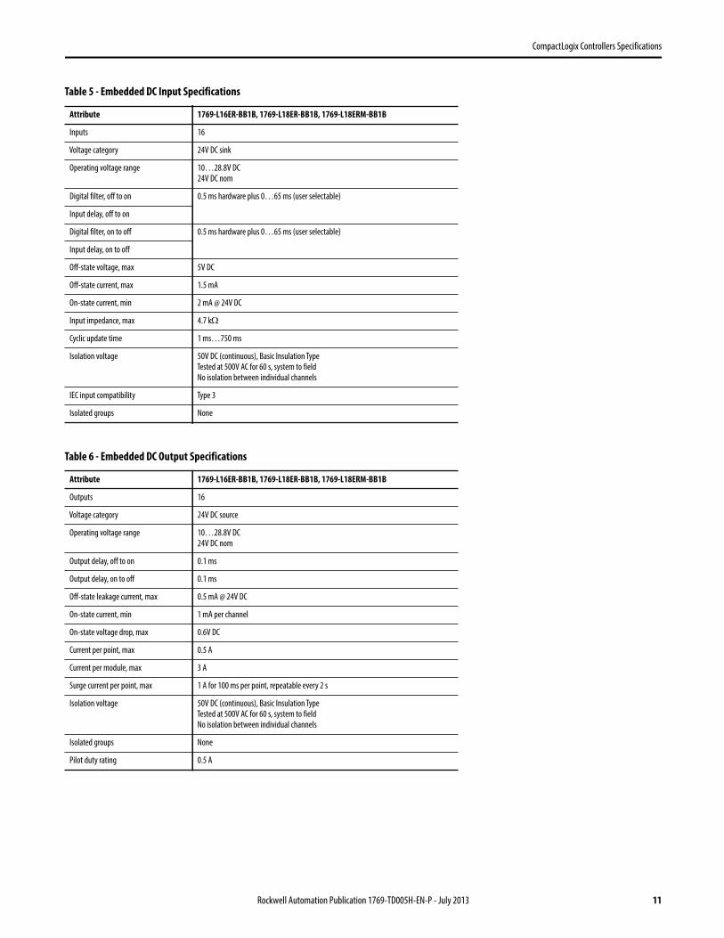
Table 5 - Embedded DC Input Specifications
Attribute 1769-L16ER-BB1B, 1769-L18ER-BB1B, 1769-L18ERM-BB1B
Inputs 16
Voltage category 24V DC sink
Operating voltage range 10…28.8V DC
24V DC nom
Digital filter, off to on 0.5 ms hardware plus 0…65 ms (user selectable)
Input delay, off to on
Digital filter, on to off 0.5 ms hardware plus 0…65 ms (user selectable)
Input delay, on to off
Off-state voltage, max 5V DC
Off-state current, max 1.5 mA
On-state current, min 2 mA @ 24V DC
Input impedance, max 4.7 k
Cyclic update time 1 ms…750 ms
Isolation voltage 50V DC (continuous), Basic Insulation Type
Tested at 500V AC for 60 s, system to field
No isolation between individual channels
IEC input compatibility Type 3
Isolated groups None
Table 6 - Embedded DC Output Specifications
Attribute 1769-L16ER-BB1B, 1769-L18ER-BB1B, 1769-L18ERM-BB1B
Outputs 16
Voltage category 24V DC source
Operating voltage range 10…28.8V DC
24V DC nom
Output delay, off to on 0.1 ms
Output delay, on to off 0.1 ms
Off-state leakage current, max 0.5 mA @ 24V DC
On-state current, min 1 mA per channel
On-state voltage drop, max 0.6V DC
Current per point, max 0.5 A
Current per module, max 3 A
Surge current per point, max 1 A for 100 ms per point, repeatable every 2 s
Isolation voltage 50V DC (continuous), Basic Insulation Type
Tested at 500V AC for 60 s, system to field
No isolation between individual channels
Isolated groups None
Pilot duty rating 0.5 A
Rockwell Automation Publication 1769-TD005H-EN-P - July 2013 11
CompactLogix Controllers Specifications
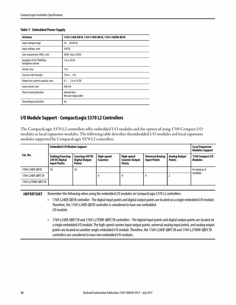
I/O Module Support - CompactLogix 5370 L2 Controllers
The CompactLogix 5370 L2 controllers offer embedded I/O modules and the option of using 1769 Compact I/O modules as local expansion modules. The following table describes theembedded I/O modules and local expansion modules supported by CompactLogix 5370 L2 controllers.
Table 7 - Embedded Power Supply
Attribute 1769-L16ER-BB1B, 1769-L18ER-BB1B, 1769-L18ERM-BB1B
Input voltage range 10…28.8V DC
Input voltage, nom 24V DC
Line requirement (VDC), min 50VA, Class 2/SELV
Available 5V DC POINTBus backplane current
1 A @ 5V DC
Inrush, max 15 A
Line loss ride through 10 ms…10 s
Output bus current capacity, max 0.1 …3 A @ 5V DC
Load current, min 300 mA
Short circuit protection Internal fuse
Not user replaceable
Overvoltage protection Yes
Cat. No.
Embedded I/O Module Support Local Expansion Modules Support
Sinking/Sourcing 24V DC Digital Input Points
Sourcing 24V DC Digital Output Points
High-speed Counters
High-speed Counter Output Points
Universal Analog Input Points
Analog Output Points
1769 Compact I/O Modules
1769-L24ER-QB1B 16 16 - - - - As many as 4 modules
1769-L24ER-QBFC1B 4 4 4 2
1769-L27ERM-QBFC1B
IMPORTANT Remember the following when using the embedded I/O modules on CompactLogix 5370 L2 controllers:
• 1769-L24ER-QB1B controller - The digital input points and digital output points are located on a single embedded I/O module.
Therefore, the 1769-L24ER-QB1B controller is considered to have one embedded
I/O module.
• 1769-L24ER-QBFC1B and 1769-L27ERM-QBFC1B controllers - The digital input points and digital output points are located on
a single embedded I/O module. The high-speed counter input output points, universal analog input points, and analog output
points are located on another single embedded I/O module. Therefore, the 1769-L24ER-QBFC1B and 1769-L27ERM-QBFC1B
controllers are considered to have two embedded I/O modules.
12 Rockwell Automation Publication 1769-TD005H-EN-P - July 2013
CompactLogix Controllers Specifications
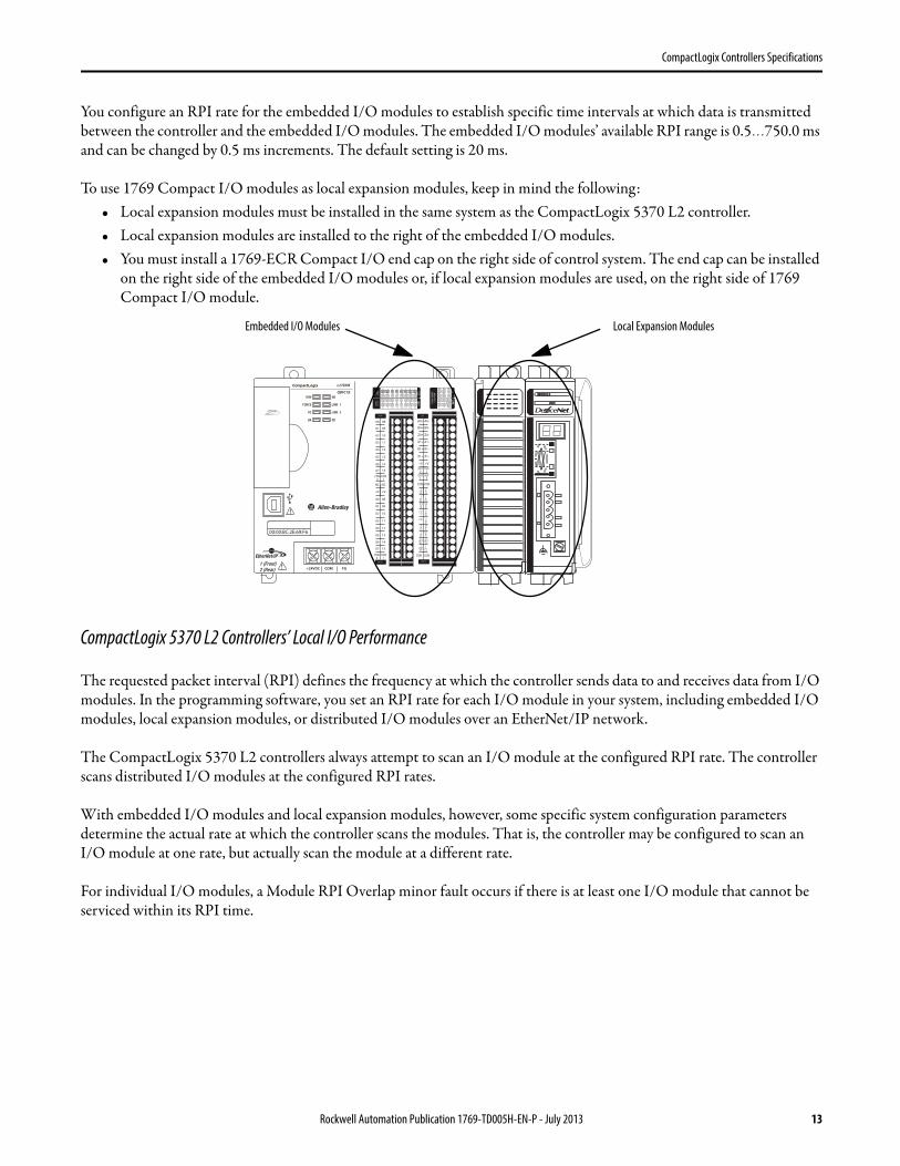
You configure an RPI rate for the embedded I/O modules to establish specific time intervals at which data is transmitted between the controller and the embedded I/O modules. The embedded I/O modules’ available RPI range is 0.5…750.0 ms and can be changed by 0.5 ms increments. The default setting is 20 ms.
To use 1769 Compact I/O modules as local expansion modules, keep in mind the following:• Local expansion modules must be installed in the same system as the CompactLogix 5370 L2 controller.• Local expansion modules are installed to the right of the embedded I/O modules.• You must install a 1769-ECR Compact I/O end cap on the right side of control system. The end cap can be installed
on the right side of the embedded I/O modules or, if local expansion modules are used, on the right side of 1769 Compact I/O module.
CompactLogix 5370 L2 Controllers’ Local I/O Performance
The requested packet interval (RPI) defines the frequency at which the controller sends data to and receives data from I/O modules. In the programming software, you set an RPI rate for each I/O module in your system, including embedded I/O modules, local expansion modules, or distributed I/O modules over an EtherNet/IP network.
The CompactLogix 5370 L2 controllers always attempt to scan an I/O module at the configured RPI rate. The controller scans distributed I/O modules at the configured RPI rates.
With embedded I/O modules and local expansion modules, however, some specific system configuration parameters determine the actual rate at which the controller scans the modules. That is, the controller may be configured to scan anI/O module at one rate, but actually scan the module at a different rate.
For individual I/O modules, a Module RPI Overlap minor fault occurs if there is at least one I/O module that cannot be serviced within its RPI time.
0 1 2 3 4 5 6 7
8 9 10 11 12 13 14 15
0 1 2 3 4 5 6 7
8 9 10
A0 B0 Z0
A1 B1 Z1
0 2 FUSE
1 3 OK11 12 13 14 15
HIG
H S
PEED
COU
NTE
R
INO
UT
DC
INPU
T
24VD
CSI
NK\
SOU
RCE
24VD
CSO
URC
E
OU
TPU
TD
C
+24VDC COM FG
0 1 2 3 4 5 6 7
8 9 10 11 12 13 14 15
0 1 2 3 4 5 6 7
8 9 10
A0 B0 Z0
A1 B1 Z1
0 2 FUSE
1 3 OK11 12 13 14 15
HIG
H S
PEED
COU
NTE
R
INO
UT
DC
INPU
T
24VD
CSI
NK\
SOU
RCE
24VD
CSO
URC
E
OU
TPU
TD
C
+24VDC COM FG
00
01
02
03
04
05
06
07
NC
+V
00
01
02
03
04
05
06
07
COM0
COM0
08
09
10
11
12
13
14
15
NC
+V
08
09
10
11
12
13
14
15
COM1
COM1
A0+
B0+
Z0+
A1+
B1+
Z1+
+V
OUT1
OUT0
COM COM
A0-
B0-
Z0-
A1-
B1-
Z1-
+V
0UT3
Vin0+
Vin2+
VOUT0+I
OUT0+
VOUT1+
Iin3+
Vin1+Iin1+
Iin1+
Vin3+
CJC-
CJC+
V/Iin1-
V/Iin3-
V/Iin0-
V/Iin2-
Iin0+
Iin2+
OUT2
COMCOM
DC IN HSC
DC OUT ANALOG
00:00:BC:2E:69:F6
L27ERM
QBFC1B
Local Expansion ModulesEmbedded I/O Modules
Rockwell Automation Publication 1769-TD005H-EN-P - July 2013 13
CompactLogix Controllers Specifications
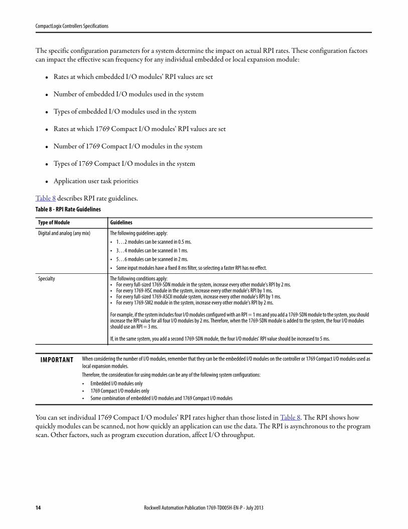
The specific configuration parameters for a system determine the impact on actual RPI rates. These configuration factors can impact the effective scan frequency for any individual embedded or local expansion module:
• Rates at which embedded I/O modules’ RPI values are set
• Number of embedded I/O modules used in the system
• Types of embedded I/O modules used in the system
• Rates at which 1769 Compact I/O modules’ RPI values are set
• Number of 1769 Compact I/O modules in the system
• Types of 1769 Compact I/O modules in the system
• Application user task priorities
Table 8 describes RPI rate guidelines.
You can set individual 1769 Compact I/O modules’ RPI rates higher than those listed in Table 8. The RPI shows how quickly modules can be scanned, not how quickly an application can use the data. The RPI is asynchronous to the program scan. Other factors, such as program execution duration, affect I/O throughput.
Table 8 - RPI Rate Guidelines
Type of Module Guidelines
Digital and analog (any mix) The following guidelines apply:
• 1…2 modules can be scanned in 0.5 ms.
• 3…4 modules can be scanned in 1 ms.
• 5…6 modules can be scanned in 2 ms.
• Some input modules have a fixed 8 ms filter, so selecting a faster RPI has no effect.
Specialty The following conditions apply:• For every full-sized 1769-SDN module in the system, increase every other module's RPI by 2 ms.• For every 1769-HSC module in the system, increase every other module's RPI by 1 ms.• For every full-sized 1769-ASCII module system, increase every other module's RPI by 1 ms.• For every 1769-SM2 module in the system, increase every other module's RPI by 2 ms.
For example, if the system includes four I/O modules configured with an RPI = 1 ms and you add a 1769-SDN module to the system, you should increase the RPI value for all four I/O modules by 2 ms. Therefore, when the 1769-SDN module is added to the system, the four I/O modules should use an RPI = 3 ms.
If, in the same system, you add a second 1769-SDN module, the four I/O modules’ RPI value should be increased to 5 ms.
IMPORTANT When considering the number of I/O modules, remember that they can be the embedded I/O modules on the controller or 1769 Compact I/O modules used as
local expansion modules.
Therefore, the consideration for using modules can be any of the following system configurations:
• Embedded I/O modules only
• 1769 Compact I/O modules only
• Some combination of embedded I/O modules and 1769 Compact I/O modules
14 Rockwell Automation Publication 1769-TD005H-EN-P - July 2013
CompactLogix Controllers Specifications
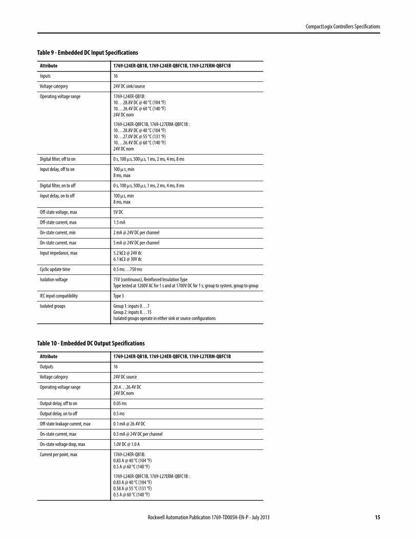
Table 9 - Embedded DC Input Specifications
Attribute 1769-L24ER-QB1B, 1769-L24ER-QBFC1B, 1769-L27ERM-QBFC1B
Inputs 16
Voltage category 24V DC sink/source
Operating voltage range 1769-L24ER-QB1B:
10…28.8V DC @ 40 °C (104 °F)
10…26.4V DC @ 60 °C (140 °F)
24V DC nom
1769-L24ER-QBFC1B, 1769-L27ERM-QBFC1B :
10…28.8V DC @ 40 °C (104 °F)
10…27.0V DC @ 55 °C (131 °F)
10…26.4V DC @ 60 °C (140 °F)
24V DC nom
Digital filter, off to on 0 s, 100 s, 500 s, 1 ms, 2 ms, 4 ms, 8 ms
Input delay, off to on 100 s, min
8 ms, max
Digital filter, on to off 0 s, 100 s, 500 s, 1 ms, 2 ms, 4 ms, 8 ms
Input delay, on to off 100 s, min
8 ms, max
Off-state voltage, max 5V DC
Off-state current, max 1.5 mA
On-state current, min 2 mA @ 24V DC per channel
On-state current, max 5 mA @ 24V DC per channel
Input impedance, max 5.2 k @ 24V dc
6.1 k @ 30V dc
Cyclic update time 0.5 ms…750 ms
Isolation voltage 75V (continuous), Reinforced Insulation Type
Type tested at 1200V AC for 1 s and at 1700V DC for 1 s; group to system, group to group
IEC input compatibility Type 3
Isolated groups Group 1: inputs 0…7
Group 2: inputs 8…15
Isolated groups operate in either sink or source configurations
Table 10 - Embedded DC Output Specifications
Attribute 1769-L24ER-QB1B, 1769-L24ER-QBFC1B, 1769-L27ERM-QBFC1B
Outputs 16
Voltage category 24V DC source
Operating voltage range 20.4…26.4V DC
24V DC nom
Output delay, off to on 0.05 ms
Output delay, on to off 0.5 ms
Off-state leakage current, max 0.1 mA @ 26.4V DC
On-state current, max 0.5 mA @ 24V DC per channel
On-state voltage drop, max 1.0V DC @ 1.0 A
Current per point, max 1769-L24ER-QB1B:
0.83 A @ 40 °C (104 °F)
0.5 A @ 60 °C (140 °F)
1769-L24ER-QBFC1B, 1769-L27ERM-QBFC1B :
0.83 A @ 40 °C (104 °F)
0.58 A @ 55 °C (131 °F)
0.5 A @ 60 °C (140 °F)
Rockwell Automation Publication 1769-TD005H-EN-P - July 2013 15
CompactLogix Controllers Specifications
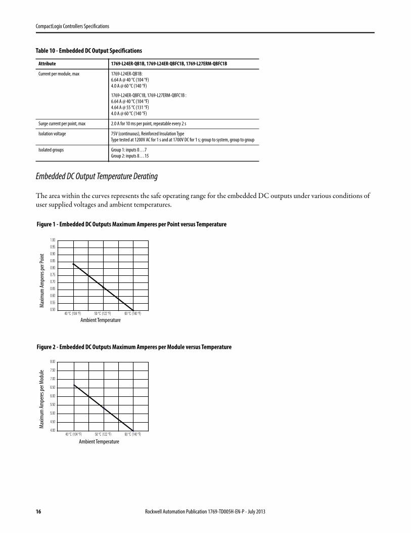
Embedded DC Output Temperature Derating
The area within the curves represents the safe operating range for the embedded DC outputs under various conditions of user supplied voltages and ambient temperatures.
Current per module, max 1769-L24ER-QB1B:
6.64 A @ 40 °C (104 °F)
4.0 A @ 60 °C (140 °F)
1769-L24ER-QBFC1B, 1769-L27ERM-QBFC1B :
6.64 A @ 40 °C (104 °F)
4.64 A @ 55 °C (131 °F)
4.0 A @ 60 °C (140 °F)
Surge current per point, max 2.0 A for 10 ms per point, repeatable every 2 s
Isolation voltage 75V (continuous), Reinforced Insulation Type
Type tested at 1200V AC for 1 s and at 1700V DC for 1 s; group to system, group to group
Isolated groups Group 1: inputs 0…7
Group 2: inputs 8…15
Table 10 - Embedded DC Output Specifications
Attribute 1769-L24ER-QB1B, 1769-L24ER-QBFC1B, 1769-L27ERM-QBFC1B
0.50
0.55
0.60
0.65
0.70
0.75
0.80
0.85
0.90
0.95
1.00
40 °C (104 °F) 50 °C (122 °F) 60 °C (140 °F)
4.00
4.50
5.00
5.50
6.00
6.50
7.00
7.50
8.00
40 °C (104 °F) 50 °C (122 °F) 60 °C (140 °F)
Figure 2 - Embedded DC Outputs Maximum Amperes per Module versus Temperature
Figure 1 - Embedded DC Outputs Maximum Amperes per Point versus Temperature
Ambient Temperature
Ambient Temperature
Max
imum
Am
pere
s per
Poi
ntM
axim
um A
mpe
res p
er M
odul
e
16 Rockwell Automation Publication 1769-TD005H-EN-P - July 2013
CompactLogix Controllers Specifications
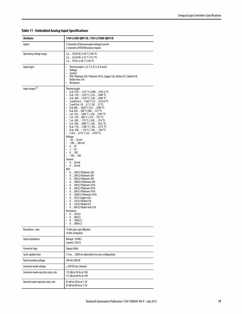
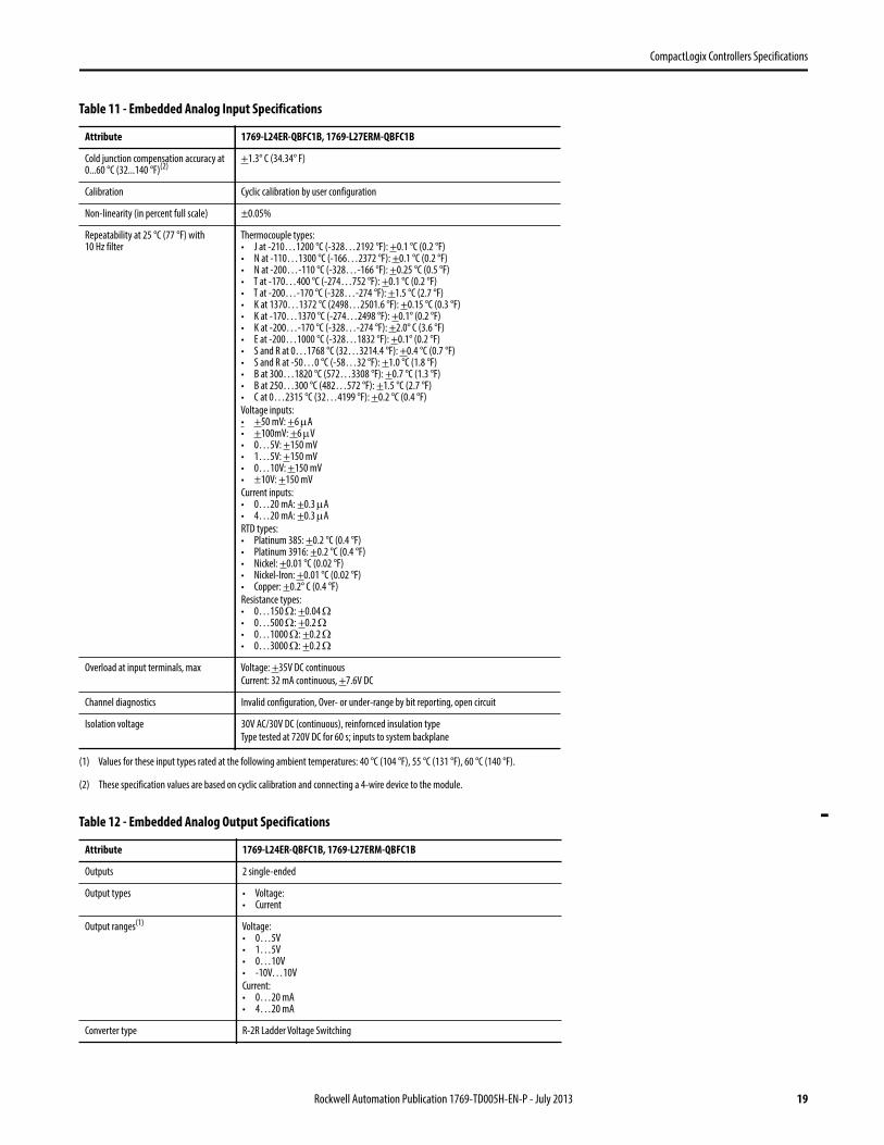
Table 11 - Embedded Analog Input Specifications
Attribute 1769-L24ER-QBFC1B, 1769-L27ERM-QBFC1B
Inputs 4 channels of thermocouple/voltage/current
2 channels of RTD/Resistance inputs
Operating voltage range 2.6…30.0V DC @ 40 °C (104 °F)
2.6…26.4V DC @ 55 °C (131 °F)
2.6…5V DC @ 60 °C (140 °F)
Input types • Thermocouple: J, K, T, E, R, S, B, N and C• Voltage• Current• RTD: Platinum 385, Platinum 3916, Copper 426, Nickel 672, Nickel 618,
Nickel-Iron 518• Resistance
Input ranges(1) Thermocouple:• K at 1370…1372 °C (2498…2501.6 °F)• K at -170…1370 °C (-274…2498 °F)• K at -200…1370 °C (-328…2498 °F)• S and R at 0…1768 °C (32…3214.4 °F)• S and R at -50…0 °C (-58…32 °F)• B at 300…1820 °C (572…3308 °F)• B at 250…300 °C (482…572 °F)• J at -210…1200 °C (-328…2192 °F)• T at -170…400 °C (-274…752 °F)• T at -200…-170 °C (-328…-274 °F)• E at -200…1000 °C (-328…1832 °F)• N at -110…1300 °C (-166…2372 °F)• N at -200…-110 °C (-328…-166 °F)• C at 0…2315 °C (32…4199 °F)
Voltage:• -50…50 mV• -100…100 mV• 0…5V• 1…5V• 0…10V• -10V…10V
Current:• 0…20 mA• 4…20 mA
RTD:• 0…100 Platinum 385• 0…200 Platinum 385• 0…500 Platinum 385• 0…1000 Platinum 385• 0…100 Platinum 3916• 0…200 Platinum 3916• 0…500 Platinum 3916• 0…1000 Platinum 3916• 0…10 Copper 426• 0…120 Nickel 618• 0…120 Nickel 672• 0…604 Nickel-Iron 518
Resistance:• 0…150 • 0…500 • 0…1000 • 0…3000
Resolution , max 15 bits plus sign (Bipolar)
16 bits (Unipolar)
Input impedance Voltage: 10 MCurrent: 250
Converter type Sigma-Delta
Cyclic update time 11 ms…5000 ms dependent on user configuration
Rated working voltage 30V AC/30V DC
Common mode voltage +10V DC per channel
Common mode rejection ratio, min 115 dB at 50 Hz at 10V
115 dB at 60 Hz at 10V
Normal mode rejection ratio, min 85 dB at 50 Hz at 1.5V
85 dB at 60 Hz at 1.5V
Rockwell Automation Publication 1769-TD005H-EN-P - July 2013 17
CompactLogix Controllers Specifications
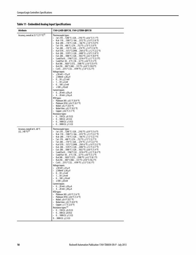
Accuracy, overall at 25 °C (77 °F)(2) Thermocouple types:• J at -210…1200 °C (-328…2192 °F): +0.6 °C (1.1 °F)• N at -110…1300 °C (-166…2372 °F): +1.0 °C (1.8 °F)• N at -200…-110 °C (-328…-166 °F): +1.0 °C (1.8 °F)• T at -170…400 °C (-274…752 °F): +1.0 °C (1.8 °F)• T at -200…-170 °C (-328…-274 °F): +1.0 °C (1.8 °F)• K at 1370…1372 °C (2498…2501.6 °F): +1.2 °C (2.2 °F)• K at -200…1370° C (-328…2498° F): +1.0° C (1.8° F)• E at -200…1000 °C (-328…1832 °F): +0.5 °C (0.9 °F)• S and R at 0…1768 °C (32…3214.4 °F): +1.7 °C (3.1°F)• S and R at -50…0 °C (-58…32 °F): +4.0 °C (7.2 °F)• B at 300…1820 °C (572…3308 °F): +3.0 °C (5.4 °F)• B at 250…300 °C (482…572 °F): +6.0 °C (10.8 °F)• C at 0…2315 °C (32…4199 °F): +1.8 °C (3.2 °F)
Voltage inputs:• +50 mV: +15 V• +100mV: +20 V• 0…5V: +2.5 mV• 1…5V: +2 mV• 0…10V: +5 mV• ±10V: +10 mV
Current inputs:• 0…20 mA: +20 A• 4…20 mA: +16 A
RTD types:• Platinum 385: +0.5 °C (0.9 °F)• Platinum 3916: +0.4 °C (0.7 °F)• Nickel: +0.2 °C (0.4 °F)• Nickel-Iron: +0.3 °C (0.5 °F)• Copper: +0.6 °C (1.1 °F)
Resistance types:• 0…150 : +0.15 • 0…500 : +0.5 • 0…1000 : +1.0 • 0…3000 : +1.5
Accuracy, overall at 0...60 °C(32...140 °F)(2)
Thermocouple types:• J at -210…1200 °C (-328…2192 °F): +0.9 °C (1.6 °F)• N at -110…1300 °C (-166…2372 °F): +1.5 °C (2.7 °F)• N at -200…-110 °C (-328…-166 °F): +1.5 °C (2.7 °F)• T at -170…400 °C (-274…752 °F): +1.5° C (2.7° F)• T at -200…-170 °C (-328…-274 °F): +1.5° C (2.7° F)• K at 1370…1372 °C (2498…2501.6 °F): +1.8 °C (3.2 °F)• K at -200…1370 °C (-328…2498 °F): +1.5 °C (2.7 °F)• E at -200…1000 °C (-328…1832 °F): +0.8 °C (1.4 °F)• S and R at 0…1768 °C (32…3214.4 °F): +3.5 °C (6.3 °F)• S and R at -50…0 °C (-58…32 °F): +4.0 °C (7.2 °F)• B at 300…1820 °C (572…3308 °F): +4.5 °C (8.1 °F)• B at 250…300 °C (482…572 °F): +9.0 °C (16.2 °F)• C at 0…2315 °C (32…4199 °F): +3.5 °C (6.3 °F)
Voltage inputs:• +50 mV: +25 V• +100mV: +30 V• 0…5V: +5 mV• 1…5V: +4 mV• 0…10V: +10 mV• ±10V: +20 mV
Current inputs:• 0…20 mA: +50 A• 4…20 mA: +40 A
RTD types:• Platinum 385: +0.9 °C (1.6 °F)• Platinum 3916: +0.8 °C (1.4 °F)• Nickel: +0.4 °C (0.7 °F)• Nickel-Iron: +0.5 °C (0.9 °F)• Copper: +1.1 °C (2.0 °F)
Resistance types:(2)
• 0…150 : +0.25 • 0…500 : +0.8 • 0…1000 : +1.5 0…3000 : +2.5
Table 11 - Embedded Analog Input Specifications
Attribute 1769-L24ER-QBFC1B, 1769-L27ERM-QBFC1B
18 Rockwell Automation Publication 1769-TD005H-EN-P - July 2013
CompactLogix Controllers Specifications
Cold junction compensation accuracy at 0...60 °C (32...140 °F)(2)
+1.3° C (34.34° F)
Calibration Cyclic calibration by user configuration
Non-linearity (in percent full scale) ±0.05%
Repeatability at 25 °C (77 °F) with 10 Hz filter
Thermocouple types:• J at -210…1200 °C (-328…2192 °F): +0.1 °C (0.2 °F)• N at -110…1300 °C (-166…2372 °F): +0.1 °C (0.2 °F)• N at -200…-110 °C (-328…-166 °F): +0.25 °C (0.5 °F)• T at -170…400 °C (-274…752 °F): +0.1 °C (0.2 °F)• T at -200…-170 °C (-328…-274 °F): +1.5 °C (2.7 °F)• K at 1370…1372 °C (2498…2501.6 °F): +0.15 °C (0.3 °F)• K at -170…1370 °C (-274…2498 °F): +0.1° (0.2 °F)• K at -200…-170 °C (-328…-274 °F): +2.0° C (3.6 °F)• E at -200…1000 °C (-328…1832 °F): +0.1° (0.2 °F)• S and R at 0…1768 °C (32…3214.4 °F): +0.4 °C (0.7 °F)• S and R at -50…0 °C (-58…32 °F): +1.0 °C (1.8 °F)• B at 300…1820 °C (572…3308 °F): +0.7 °C (1.3 °F)• B at 250…300 °C (482…572 °F): +1.5 °C (2.7 °F)• C at 0…2315 °C (32…4199 °F): +0.2 °C (0.4 °F)
Voltage inputs:• +50 mV: +6 A• +100mV: +6 V• 0…5V: +150 mV• 1…5V: +150 mV• 0…10V: +150 mV• ±10V: +150 mV
Current inputs:• 0…20 mA: +0.3 A• 4…20 mA: +0.3 A
RTD types:• Platinum 385: +0.2 °C (0.4 °F)• Platinum 3916: +0.2 °C (0.4 °F)• Nickel: +0.01 °C (0.02 °F)• Nickel-Iron: +0.01 °C (0.02 °F)• Copper: +0.2° C (0.4 °F)
Resistance types:• 0…150 : +0.04 • 0…500 : +0.2 • 0…1000 : +0.2 • 0…3000 : +0.2
Overload at input terminals, max Voltage: +35V DC continuous
Current: 32 mA continuous, +7.6V DC
Channel diagnostics Invalid configuration, Over- or under-range by bit reporting, open circuit
Isolation voltage 30V AC/30V DC (continuous), reinfornced insulation type
Type tested at 720V DC for 60 s; inputs to system backplane
(1) Values for these input types rated at the following ambient temperatures: 40 °C (104 °F), 55 °C (131 °F), 60 °C (140 °F).
(2) These specification values are based on cyclic calibration and connecting a 4-wire device to the module.
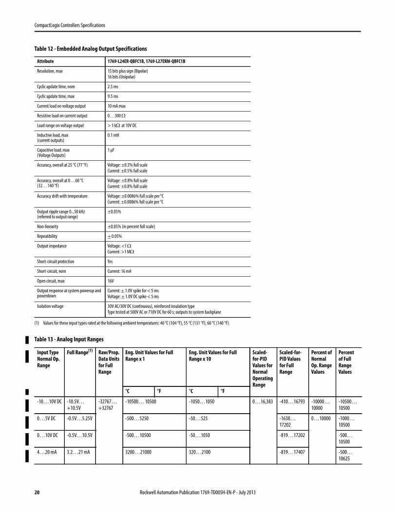
Table 12 - Embedded Analog Output Specifications
Attribute 1769-L24ER-QBFC1B, 1769-L27ERM-QBFC1B
Outputs 2 single-ended
Output types • Voltage:• Current
Output ranges(1) Voltage:• 0…5V• 1…5V• 0…10V• -10V…10V
Current:• 0…20 mA• 4…20 mA
Converter type R-2R Ladder Voltage Switching
Table 11 - Embedded Analog Input Specifications
Attribute 1769-L24ER-QBFC1B, 1769-L27ERM-QBFC1B
Rockwell Automation Publication 1769-TD005H-EN-P - July 2013 19
CompactLogix Controllers Specifications
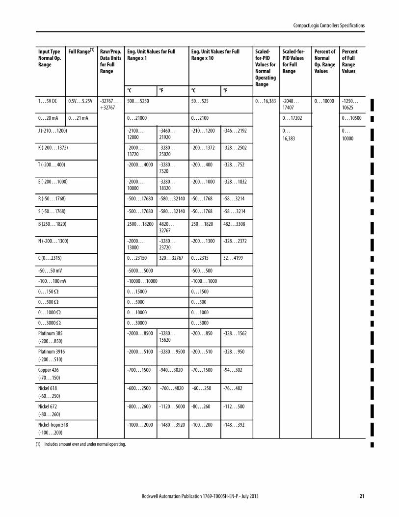
Table 13 - Analog Input Ranges
Resolution, max 15 bits plus sign (Bipolar)
16 bits (Unipolar)
Cyclic update time, nom 2.5 ms
Cyclic update time, max 9.5 ms
Current load on voltage output 10 mA max
Resistive load on current output 0…300
Load range on voltage output > 1 kat 10V DC
Inductive load, max(current outputs)
0.1 mH
Capacitive load, max(Voltage Outputs)
1 µF
Accuracy, overall at 25 °C (77 °F) Voltage: ±0.5% full scale
Current: ±0.5% full scale
Accuracy, overall at 0…60 °C(32…140 °F)
Voltage: ±0.8% full scale
Current: ±0.8% full scale
Accuracy drift with temperature Voltage: ±0.0086% full scale per °C
Current: ±0.0086% full scale per °C
Output ripple range 0...50 kHz(referred to output range)
±0.05%
Non-linearity ±0.05% (in percent full scale)
Repeatibility + 0.05%
Output impedance Voltage: <1 Current: >1 M
Short-circuit protection Yes
Short-circuit, nom Current: 16 mA
Open circuit, max 16V
Output response at system powerup and powerdown
Current: + 1.0V spike for < 5 ms
Voltage: + 1.0V DC spike < 5 ms
Isolation voltage 30V AC/30V DC (continuous), reinforced insulation type
Type tested at 500V AC or 710V DC for 60 s; outputs to system backplane
(1) Values for these input types rated at the following ambient temperatures: 40 °C (104 °F), 55 °C (131 °F), 60 °C (140 °F).
Input Type Normal Op. Range
Full Range(1) Raw/Prop. Data Units for Full Range
Eng. Unit Values for Full Range x 1
Eng. Unit Values for Full Range x 10
Scaled-for-PID Values for Normal Operating Range
Scaled-for-PID Values for Full Range
Percent of Normal Op. Range Values
Percent of Full Range Values
°C °F °C °F
-10…10V DC -10.5V…+10.5V
-32767…+32767
-10500… 10500 -1050…1050 0…16,383 -410…16793 -10000…10000
-10500…10500
0…5V DC -0.5V…5.25V -500…5250 -50…525 -1638…17202
0…10000 -1000…10500
0…10V DC -0.5V…10.5V -500…10500 -50…1050 -819…17202 -500…10500
4…20 mA 3.2…21 mA 3200…21000 320…2100 -819…17407 -500…10625
Table 12 - Embedded Analog Output Specifications
Attribute 1769-L24ER-QBFC1B, 1769-L27ERM-QBFC1B
20 Rockwell Automation Publication 1769-TD005H-EN-P - July 2013
CompactLogix Controllers Specifications
1…5V DC 0.5V…5.25V -32767…+32767
500…5250 50…525 0…16,383 -2048…17407
0…10000 -1250…10625
0…20 mA 0…21 mA 0…21000 0…2100 0…17202 0…10500
J (-210…1200) -2100…12000
-3460…21920
-210…1200 -346…2192 0…
16,383
0…
10000
K (-200…1372) -2000… 13720
-3280…25020
-200…1372 -328…2502
T (-200…400) -2000…4000 -3280…7520
-200…400 -328…752
E (-200…1000) -2000…10000
-3280…18320
-200…1000 -328…1832
R (-50…1768) -500…17680 -580…32140 -50…1768 -58…3214
S (-50…1768) -500…17680 -580…32140 -50…1768 -58 …3214
B (250…1820) 2500…18200 4820…32767
250…1820 482…3308
N (-200…1300) -2000…13000
-3280…23720
-200…1300 -328…2372
C (0…2315) 0…23150 320…32767 0…2315 32…4199
-50…50 mV -5000…5000 -500…500
-100…100 mV -10000…10000 -1000…1000
0…150 0…15000 0…1500
0…500 0…5000 0…500
0…1000 0…10000 0…1000
0…3000 0…30000 0…3000
Platinum 385
(-200…850)
-2000…8500 -3280…15620
-200…850 -328…1562
Platinum 3916
(-200…510)
-2000…5100 -3280…9500 -200…510 -328…950
Copper 426
(-70…150)
-700…1500 -940…3020 -70…1500 -94…302
Nickel 618
(-60…250)
-600…2500 -760…4820 -60…250 -76…482
Nickel 672
(-80…260)
-800…2600 -1120…5000 -80…260 -112…500
Nickel-Iropn 518
(-100…200)
-1000…2000 -1480…3920 -100…200 -148…392
(1) Includes amount over and under normal operating.
Input Type Normal Op. Range
Full Range(1) Raw/Prop. Data Units for Full Range
Eng. Unit Values for Full Range x 1
Eng. Unit Values for Full Range x 10
Scaled-for-PID Values for Normal Operating Range
Scaled-for-PID Values for Full Range
Percent of Normal Op. Range Values
Percent of Full Range Values
°C °F °C °F
Rockwell Automation Publication 1769-TD005H-EN-P - July 2013 21
CompactLogix Controllers Specifications
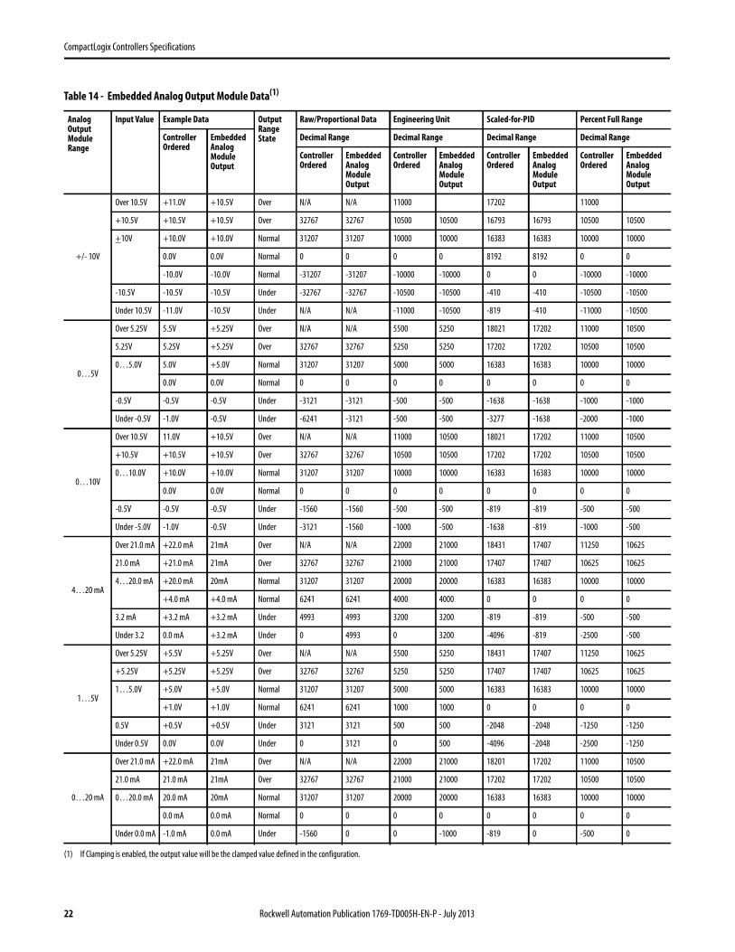
Table 14 - Embedded Analog Output Module Data(1)
(1) If Clamping is enabled, the output value will be the clamped value defined in the configuration.
Analog Output Module Range
Input Value Example Data Output Range State
Raw/Proportional Data Engineering Unit Scaled-for-PID Percent Full Range
Controller Ordered
Embedded Analog Module Output
Decimal Range Decimal Range Decimal Range Decimal Range
Controller Ordered
Embedded Analog Module Output
Controller Ordered
Embedded Analog Module Output
Controller Ordered
Embedded Analog Module Output
Controller Ordered
Embedded Analog Module Output
+/- 10V
Over 10.5V +11.0V +10.5V Over N/A N/A 11000 17202 11000
+10.5V +10.5V +10.5V Over 32767 32767 10500 10500 16793 16793 10500 10500
+10V +10.0V +10.0V Normal 31207 31207 10000 10000 16383 16383 10000 10000
0.0V 0.0V Normal 0 0 0 0 8192 8192 0 0
-10.0V -10.0V Normal -31207 -31207 -10000 -10000 0 0 -10000 -10000
-10.5V -10.5V -10.5V Under -32767 -32767 -10500 -10500 -410 -410 -10500 -10500
Under 10.5V -11.0V -10.5V Under N/A N/A -11000 -10500 -819 -410 -11000 -10500
0…5V
Over 5.25V 5.5V +5.25V Over N/A N/A 5500 5250 18021 17202 11000 10500
5.25V 5.25V +5.25V Over 32767 32767 5250 5250 17202 17202 10500 10500
0…5.0V 5.0V +5.0V Normal 31207 31207 5000 5000 16383 16383 10000 10000
0.0V 0.0V Normal 0 0 0 0 0 0 0 0
-0.5V -0.5V -0.5V Under -3121 -3121 -500 -500 -1638 -1638 -1000 -1000
Under -0.5V -1.0V -0.5V Under -6241 -3121 -500 -500 -3277 -1638 -2000 -1000
0…10V
Over 10.5V 11.0V +10.5V Over N/A N/A 11000 10500 18021 17202 11000 10500
+10.5V +10.5V +10.5V Over 32767 32767 10500 10500 17202 17202 10500 10500
0…10.0V +10.0V +10.0V Normal 31207 31207 10000 10000 16383 16383 10000 10000
0.0V 0.0V Normal 0 0 0 0 0 0 0 0
-0.5V -0.5V -0.5V Under -1560 -1560 -500 -500 -819 -819 -500 -500
Under -5.0V -1.0V -0.5V Under -3121 -1560 -1000 -500 -1638 -819 -1000 -500
4…20 mA
Over 21.0 mA +22.0 mA 21mA Over N/A N/A 22000 21000 18431 17407 11250 10625
21.0 mA +21.0 mA 21mA Over 32767 32767 21000 21000 17407 17407 10625 10625
4…20.0 mA +20.0 mA 20mA Normal 31207 31207 20000 20000 16383 16383 10000 10000
+4.0 mA +4.0 mA Normal 6241 6241 4000 4000 0 0 0 0
3.2 mA +3.2 mA +3.2 mA Under 4993 4993 3200 3200 -819 -819 -500 -500
Under 3.2 0.0 mA +3.2 mA Under 0 4993 0 3200 -4096 -819 -2500 -500
1…5V
Over 5.25V +5.5V +5.25V Over N/A N/A 5500 5250 18431 17407 11250 10625
+5.25V +5.25V +5.25V Over 32767 32767 5250 5250 17407 17407 10625 10625
1…5.0V +5.0V +5.0V Normal 31207 31207 5000 5000 16383 16383 10000 10000
+1.0V +1.0V Normal 6241 6241 1000 1000 0 0 0 0
0.5V +0.5V +0.5V Under 3121 3121 500 500 -2048 -2048 -1250 -1250
Under 0.5V 0.0V 0.0V Under 0 3121 0 500 -4096 -2048 -2500 -1250
0…20 mA
Over 21.0 mA +22.0 mA 21mA Over N/A N/A 22000 21000 18201 17202 11000 10500
21.0 mA 21.0 mA 21mA Over 32767 32767 21000 21000 17202 17202 10500 10500
0…20.0 mA 20.0 mA 20mA Normal 31207 31207 20000 20000 16383 16383 10000 10000
0.0 mA 0.0 mA Normal 0 0 0 0 0 0 0 0
Under 0.0 mA -1.0 mA 0.0 mA Under -1560 0 0 -1000 -819 0 -500 0
22 Rockwell Automation Publication 1769-TD005H-EN-P - July 2013
CompactLogix Controllers Specifications
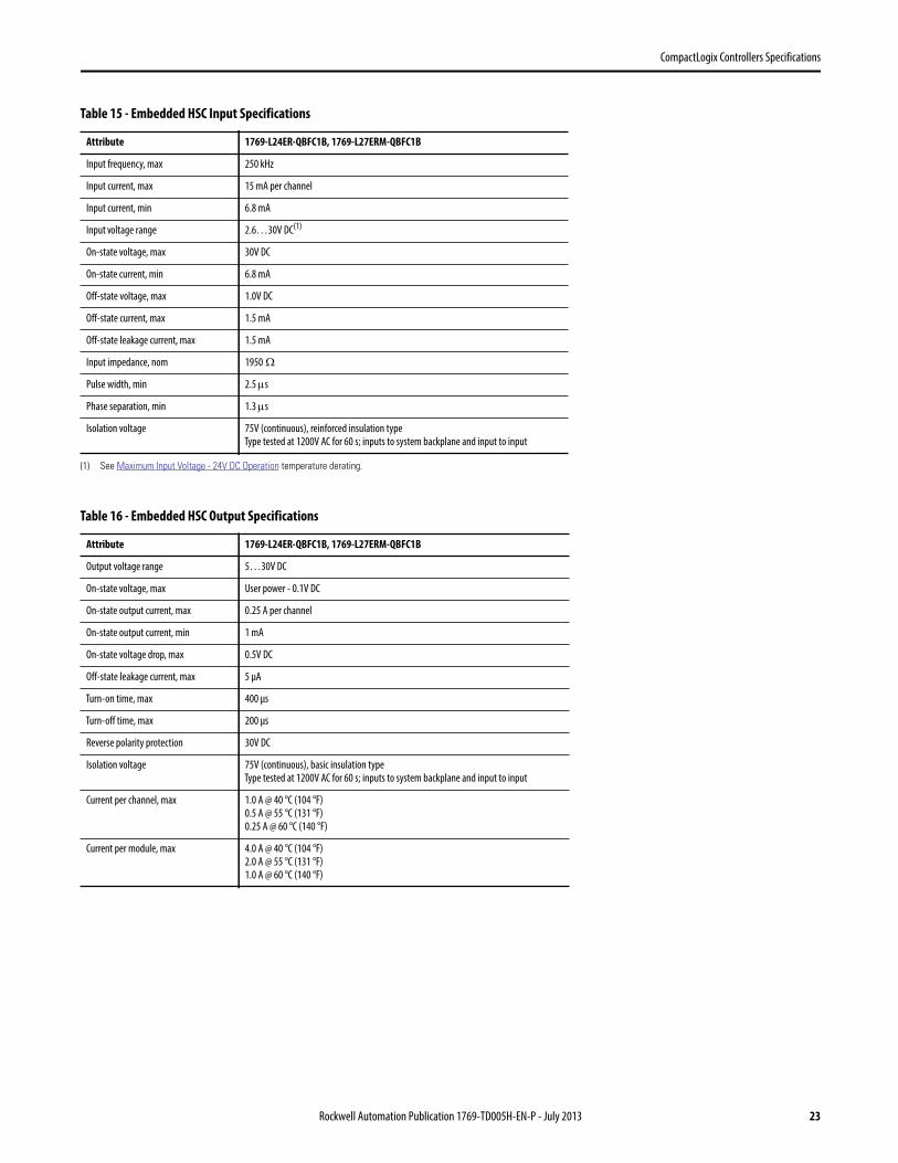
Table 15 - Embedded HSC Input Specifications
Attribute 1769-L24ER-QBFC1B, 1769-L27ERM-QBFC1B
Input frequency, max 250 kHz
Input current, max 15 mA per channel
Input current, min 6.8 mA
Input voltage range 2.6…30V DC(1)
(1) See Maximum Input Voltage - 24V DC Operation temperature derating.
On-state voltage, max 30V DC
On-state current, min 6.8 mA
Off-state voltage, max 1.0V DC
Off-state current, max 1.5 mA
Off-state leakage current, max 1.5 mA
Input impedance, nom 1950
Pulse width, min 2.5 s
Phase separation, min 1.3 s
Isolation voltage 75V (continuous), reinforced insulation type
Type tested at 1200V AC for 60 s; inputs to system backplane and input to input
Table 16 - Embedded HSC Output Specifications
Attribute 1769-L24ER-QBFC1B, 1769-L27ERM-QBFC1B
Output voltage range 5…30V DC
On-state voltage, max User power - 0.1V DC
On-state output current, max 0.25 A per channel
On-state output current, min 1 mA
On-state voltage drop, max 0.5V DC
Off-state leakage current, max 5 µA
Turn-on time, max 400 µs
Turn-off time, max 200 µs
Reverse polarity protection 30V DC
Isolation voltage 75V (continuous), basic insulation type
Type tested at 1200V AC for 60 s; inputs to system backplane and input to input
Current per channel, max 1.0 A @ 40 °C (104 °F)
0.5 A @ 55 °C (131 °F)
0.25 A @ 60 °C (140 °F)
Current per module, max 4.0 A @ 40 °C (104 °F)
2.0 A @ 55 °C (131 °F)
1.0 A @ 60 °C (140 °F)
Rockwell Automation Publication 1769-TD005H-EN-P - July 2013 23

CompactLogix Controllers Specifications
Embedded HSC Temperature Derating
Figure 3 - Maximum Input Voltage - 24V DC Operation
Figure 4 - Maximum Output Voltage - 24V DC Operation
Temperature Derated Voltage(1)
(1) Input voltage derating between 55 °C and 60 °C (131 °F and 140 °F) is achieved by using a dropping resistor.For 24V DC input voltage, use a 2.4 k, 1/2 W resistor.For input voltages other than 24V DC, use a 1/2 W resistor with value: 125 x (Vin - 5V).
40 °C (104 °F) 30V DC
55 °C (131 °F) 26.4V DC
60 °C (140 °F) 5V DC
Temperature Derated Voltage
40 °C (104 °F) 30V DC
55…60 °C (131...140 °F) 26.4V DC
05
101520253035
0 (32) 10 (50) 20 (68) 30 (86) 40 (104) 50 (122) 60 (140) 70 (158)
Voltage Derating Based on Temperature
Ambient Temperature °C (°F)
Volts
(DC) 26.4V DC @ 55 °C (131 °F)
26
27
28
29
30
31
0 (32) 10 (50) 20 (68) 30 (86) 40 (104) 50 (122) 60 (140) 70 (158)
Voltage Derating Based on Temperature
Volts
(DC)
Ambient Temperature °C (°F)
26.4V DC @ 55 °C (131 °F)
24 Rockwell Automation Publication 1769-TD005H-EN-P - July 2013
CompactLogix Controllers Specifications
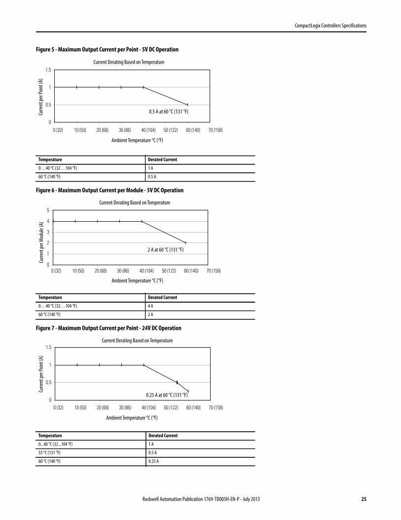
Figure 5 - Maximum Output Current per Point - 5V DC Operation
Figure 6 - Maximum Output Current per Module - 5V DC Operation
Figure 7 - Maximum Output Current per Point - 24V DC Operation
Temperature Derated Current
0…40 °C (32…104 °F) 1 A
60 °C (140 °F) 0.5 A
Temperature Derated Current
0…40 °C (32…104 °F) 4 A
60 °C (140 °F) 2 A
Temperature Derated Current
0...40 °C (32...104 °F) 1 A
55 °C (131 °F) 0.5 A
60 °C (140 °F) 0.25 A
0
0.5
1
1.5
0 (32) 10 (50) 20 (68) 30 (86) 40 (104) 50 (122) 60 (140) 70 (158)
Current Derating Based on Temperature
Ambient Temperature °C (°F)
Curr
ent p
er P
oint
(A)
0.5 A at 60 °C (131 °F)
0
1
2
3
4
5
0 (32) 10 (50) 20 (68) 30 (86) 40 (104) 50 (122) 60 (140) 70 (158)
Current Derating Based on Temperature
Ambient Temperature °C (°F)
Curr
ent p
er M
odul
e (A
)
2 A at 60 °C (131 °F)
0
0.5
1
1.5
0 (32) 10 (50) 20 (68) 30 (86) 40 (104) 50 (122) 60 (140) 70 (158)
Current Derating Based on Temperature
Ambient Temperature °C (°F)
Curr
ent p
er P
oint
(A)
0.25 A at 60 °C (131 °F)
Rockwell Automation Publication 1769-TD005H-EN-P - July 2013 25
CompactLogix Controllers Specifications
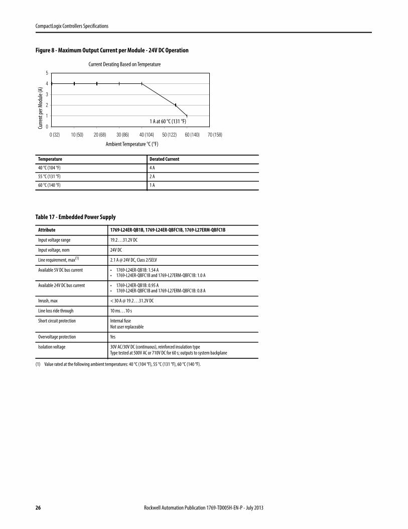
Figure 8 - Maximum Output Current per Module - 24V DC Operation
Temperature Derated Current
40 °C (104 °F) 4 A
55 °C (131 °F) 2 A
60 °C (140 °F) 1 A
Table 17 - Embedded Power Supply
Attribute 1769-L24ER-QB1B, 1769-L24ER-QBFC1B, 1769-L27ERM-QBFC1B
Input voltage range 19.2…31.2V DC
Input voltage, nom 24V DC
Line requirement, max(1)
(1) Value rated at the following ambient temperatures: 40 °C (104 °F), 55 °C (131 °F), 60 °C (140 °F).
2.1 A @ 24V DC, Class 2/SELV
Available 5V DC bus current • 1769-L24ER-QB1B: 1.54 A• 1769-L24ER-QBFC1B and 1769-L27ERM-QBFC1B: 1.0 A
Available 24V DC bus current • 1769-L24ER-QB1B: 0.95 A• 1769-L24ER-QBFC1B and 1769-L27ERM-QBFC1B: 0.8 A
Inrush, max < 30 A @ 19.2…31.2V DC
Line loss ride through 10 ms…10 s
Short circuit protection Internal fuse
Not user replaceable
Overvoltage protection Yes
Isolation voltage 30V AC/30V DC (continuous), reinforced insulation type
Type tested at 500V AC or 710V DC for 60 s; outputs to system backplane
0
1
2
3
4
5
0 (32) 10 (50) 20 (68) 30 (86) 40 (104) 50 (122) 60 (140) 70 (158)
Current Derating Based on Temperature
Ambient Temperature °C (°F)
Curr
ent p
er M
odul
e (A
)
1 A at 60 °C (131 °F)
26 Rockwell Automation Publication 1769-TD005H-EN-P - July 2013
CompactLogix Controllers Specifications
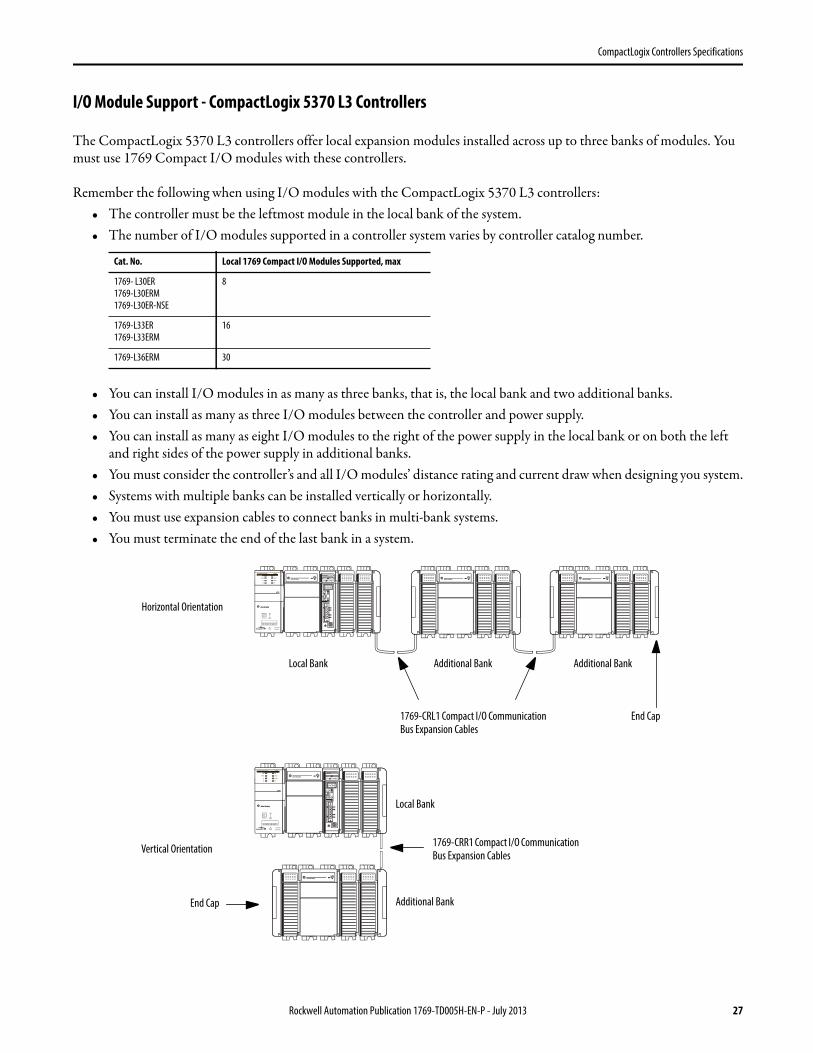
I/O Module Support - CompactLogix 5370 L3 Controllers
The CompactLogix 5370 L3 controllers offer local expansion modules installed across up to three banks of modules. You must use 1769 Compact I/O modules with these controllers.
Remember the following when using I/O modules with the CompactLogix 5370 L3 controllers:• The controller must be the leftmost module in the local bank of the system.• The number of I/O modules supported in a controller system varies by controller catalog number.
• You can install I/O modules in as many as three banks, that is, the local bank and two additional banks.• You can install as many as three I/O modules between the controller and power supply.• You can install as many as eight I/O modules to the right of the power supply in the local bank or on both the left
and right sides of the power supply in additional banks.• You must consider the controller’s and all I/O modules’ distance rating and current draw when designing you system.• Systems with multiple banks can be installed vertically or horizontally.• You must use expansion cables to connect banks in multi-bank systems.• You must terminate the end of the last bank in a system.
Cat. No. Local 1769 Compact I/O Modules Supported, max
1769- L30ER
1769-L30ERM
1769-L30ER-NSE
8
1769-L33ER
1769-L33ERM
16
1769-L36ERM 30
1 (Front)2 (Rear)
00:00:BC:2E:69:F6
1 (Front)2 (Rear)
00:00:BC:2E:69:F6
Horizontal Orientation
Vertical Orientation
Local Bank Additional Bank
Additional Bank
Additional Bank
Local Bank
1769-CRL1 Compact I/O Communication Bus Expansion Cables
1769-CRR1 Compact I/O Communication Bus Expansion Cables
End Cap
End Cap
Rockwell Automation Publication 1769-TD005H-EN-P - July 2013 27
CompactLogix Controllers Specifications
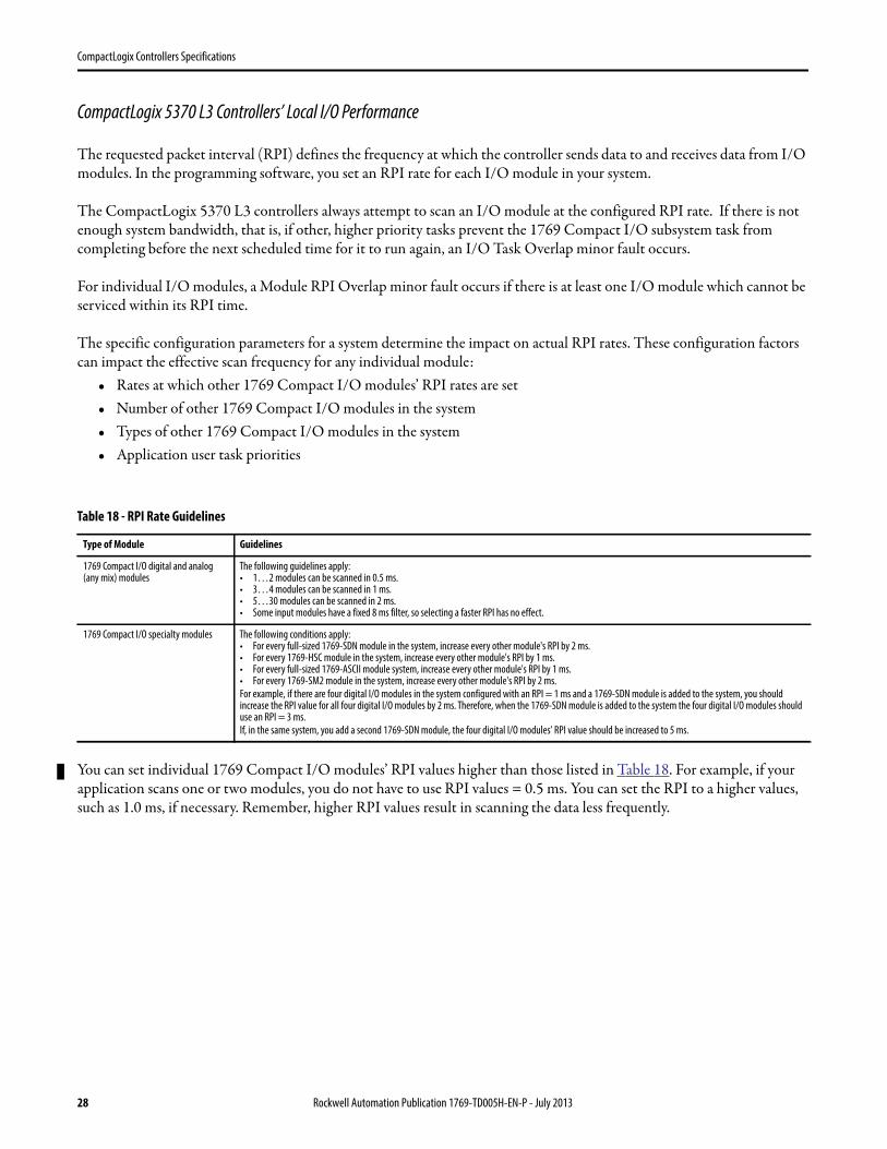
CompactLogix 5370 L3 Controllers’ Local I/O Performance
The requested packet interval (RPI) defines the frequency at which the controller sends data to and receives data from I/O modules. In the programming software, you set an RPI rate for each I/O module in your system.
The CompactLogix 5370 L3 controllers always attempt to scan an I/O module at the configured RPI rate. If there is not enough system bandwidth, that is, if other, higher priority tasks prevent the 1769 Compact I/O subsystem task from completing before the next scheduled time for it to run again, an I/O Task Overlap minor fault occurs.
For individual I/O modules, a Module RPI Overlap minor fault occurs if there is at least one I/O module which cannot be serviced within its RPI time.
The specific configuration parameters for a system determine the impact on actual RPI rates. These configuration factors can impact the effective scan frequency for any individual module:
• Rates at which other 1769 Compact I/O modules’ RPI rates are set• Number of other 1769 Compact I/O modules in the system• Types of other 1769 Compact I/O modules in the system• Application user task priorities
You can set individual 1769 Compact I/O modules’ RPI values higher than those listed in Table 18. For example, if your application scans one or two modules, you do not have to use RPI values = 0.5 ms. You can set the RPI to a higher values, such as 1.0 ms, if necessary. Remember, higher RPI values result in scanning the data less frequently.
Table 18 - RPI Rate Guidelines
Type of Module Guidelines
1769 Compact I/O digital and analog (any mix) modules
The following guidelines apply:• 1…2 modules can be scanned in 0.5 ms.• 3…4 modules can be scanned in 1 ms.• 5…30 modules can be scanned in 2 ms.• Some input modules have a fixed 8 ms filter, so selecting a faster RPI has no effect.
1769 Compact I/O specialty modules The following conditions apply:• For every full-sized 1769-SDN module in the system, increase every other module's RPI by 2 ms.• For every 1769-HSC module in the system, increase every other module's RPI by 1 ms.• For every full-sized 1769-ASCII module system, increase every other module's RPI by 1 ms.• For every 1769-SM2 module in the system, increase every other module's RPI by 2 ms.
For example, if there are four digital I/O modules in the system configured with an RPI = 1 ms and a 1769-SDN module is added to the system, you should increase the RPI value for all four digital I/O modules by 2 ms. Therefore, when the 1769-SDN module is added to the system the four digital I/O modules should use an RPI = 3 ms.
If, in the same system, you add a second 1769-SDN module, the four digital I/O modules’ RPI value should be increased to 5 ms.
28 Rockwell Automation Publication 1769-TD005H-EN-P - July 2013
CompactLogix Controllers Specifications
The RPI is asynchronous to the program scan. Other factors, such as program execution duration, affect I/O throughput.
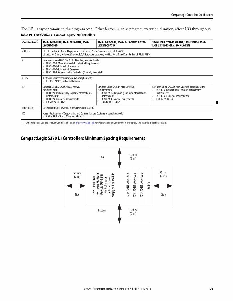
CompactLogix 5370 L1 Controllers Minimum Spacing Requirements
Table 19 - Certifications - CompactLogix 5370 Controllers
Certification(1)
(1) When marked. See the Product Certification link at http://www.ab.com for Declarations of Conformity, Certificates, and other certification details.
1769-L16ER-BB1B, 1769-L18ER-BB1B, 1769-L18ERM-BB1B
1769-L24ER-QB1B, 1769-L24ER-QBFC1B, 1769-L27ERM-QBFC1B
1769-L30ER, 1769-L30ER-NSE, 1769-L30ERM, 1769-L33ER, 1769-L33ERM, 1769-L36ERM
c-UL-us UL Listed Industrial Control Equipment, certified for US and Canada. See UL File E65584.
UL Listed for Class I, Division 2 Group A,B,C,D Hazardous Locations, certified for U.S. and Canada. See UL File E194810.
CE European Union 2004/108/EC EMC Directive, compliant with:• EN 61326-1; Meas./Control/Lab., Industrial Requirements• EN 61000-6-2; Industrial Immunity• EN 61000-6-4; Industrial Emissions• EN 61131-2; Programmable Controllers (Clause 8, Zone A & B)
C-Tick Australian Radiocommunications Act, compliant with:• AS/NZS CISPR 11; Industrial Emissions
Ex European Union 94/9/EC ATEX Directive, compliant with:• EN 60079-15; Potentially Explosive Atmospheres,
Protection "n"• EN 60079-0; General Requirements• II 3 G Ex nA IIC T4 Gc
European Union 94/9/EC ATEX Directive, compliant with:• EN 60079-15; Potentially Explosive Atmospheres,
Protection "n"• EN 60079-0; General Requirements• II 3 G Ex nA IIC T4 Gc
European Union 94/9/EC ATEX Directive, compliant with:• EN 60079-15; Potentially Explosive Atmospheres,
Protection "n"• EN 60079-0; General Requirements• II 3 G Ex nA IIC T5 X
EtherNet/IP ODVA conformance tested to EtherNet/IP specifications.
KC Korean Registration of Broadcasting and Communications Equipment, compliant with:• Article 58-2 of Radio Waves Act, Clause 3
Bottom
Top
1769
-L16
ER-B
B1B,
17
69-L
18ER
-BB1
BB, o
r17
69-L
18ER
M-B
B1B
Cont
rolle
r with
Em
bedd
ed P
ower
Su
pply
and
I/O
Mod
ule
End
Cap
50 mm(2 in.)
50 mm(2 in.)
50 mm(2 in.)
50 mm(2 in.)
Side Side1734
POI
NT
I/O
Mod
ule
1734
POI
NT
I/O
Mod
ule
1734
POI
NT
I/O
Mod
ule
Rockwell Automation Publication 1769-TD005H-EN-P - July 2013 29
CompactLogix Controllers Specifications
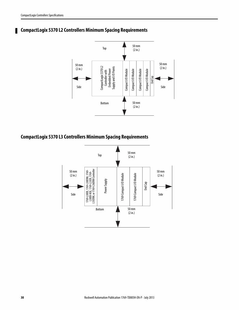
CompactLogix 5370 L2 Controllers Minimum Spacing Requirements
CompactLogix 5370 L3 Controllers Minimum Spacing Requirements
Bottom
Top
Com
pact
Logi
x 53
70 L
2 Co
ntro
ller w
ith
Embe
dded
Pow
er
Supp
ly a
nd I/
O Po
ints
End
Cap
50 mm(2 in.)
50 mm(2 in.)
50 mm(2 in.)
50 mm(2 in.)
Side Side
Com
pact
I/O
Mod
ule
Com
pact
I/O
Mod
ule
Com
pact
I/O
Mod
ule
Com
pact
I/O
Mod
ule
1769
-L30
ER, 1
769-
L30E
RM, 1
769-
L30E
R-N
SE, 1
769-
L33E
R, 1
769-
L33E
RM, o
r 176
9-L3
6ERM
Con
trol
ler
Pow
er S
uppl
y
1769
Com
pact
I/O
Mod
ule
Top50 mm(2 in.)
Bottom
50 mm(2 in.)
50 mm(2 in.)
50 mm(2 in.)
Side Side
End
Cap
1769
Com
pact
I/O
Mod
ule
30 Rockwell Automation Publication 1769-TD005H-EN-P - July 2013
CompactLogix Controllers Specifications
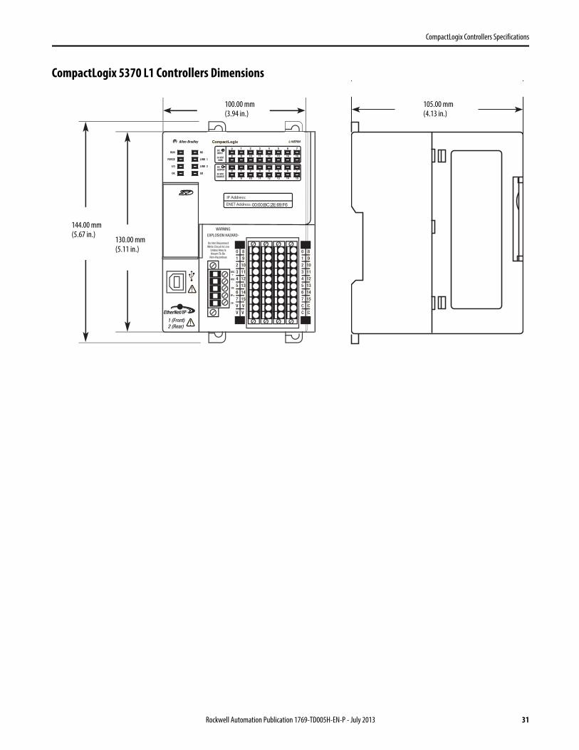
CompactLogix 5370 L1 Controllers Dimensions
00:00:BC:2E:69:F6
144.00 mm(5.67 in.)
130.00 mm(5.11 in.)
100.00 mm(3.94 in.)
105.00 mm(4.13 in.)
Rockwell Automation Publication 1769-TD005H-EN-P - July 2013 31
CompactLogix Controllers Specifications
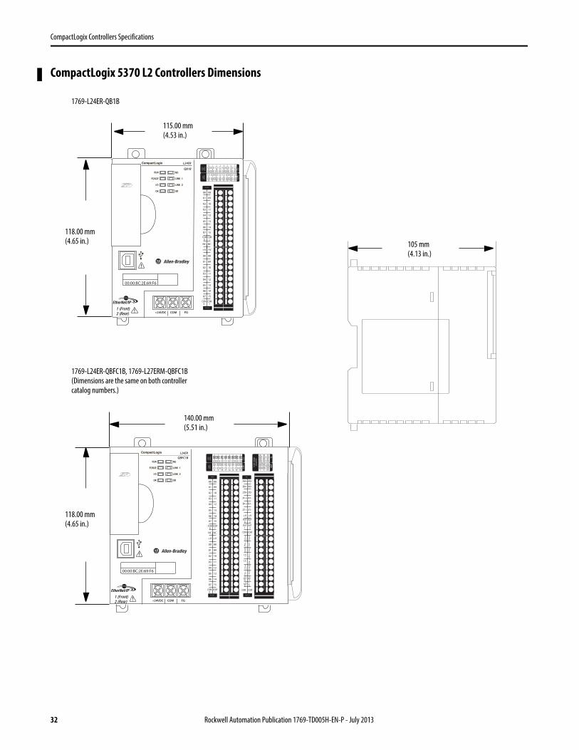
CompactLogix 5370 L2 Controllers Dimensions
0 1 2 3 4 5 6 7
8 9 10 11 12 13 14 15
0 1 2 3 4 5 6 7
8 9 10
A0 B0 Z0
A1 B1 Z1
0 2 FUSE
1 3 OK11 12 13 14 15
HIG
H S
PEED
COU
NTE
R
INO
UT
DC
INPU
T
24VD
CSI
NK\
SOU
RCE
24VD
CSO
URC
E
OU
TPU
TD
C
+24VDC COM FG
00
01
02
03
04
05
06
07
NC
+V
00
01
02
03
04
05
06
07
COM0
COM0
08
09
10
11
12
13
14
15
NC
+V
08
09
10
11
12
13
14
15
COM1
COM1
A0+
B0+
Z0+
A1+
B1+
Z1+
+V
OUT1
OUT0
COM COM
A0-
B0-
Z0-
A1-
B1-
Z1-
+V
0UT3
Vin0+
Vin2+
VOUT0+I
OUT0+
VOUT1+
Iin3+
Vin1+Iin1+
Iin1+
Vin3+
CJC-
CJC+
V/Iin1-
V/Iin3-
V/Iin0-
V/Iin2-
Iin0+
Iin2+
OUT2
COMCOM
DC IN HSC
DC OUT ANALOG
00:00:BC:2E:69:F6
QBFC1B
00:00:BC:2E:69:F6
L24ER0 1 2 3 4 5 6 7
8 9 10 11 12 13 14 15
0 1 2 3 4 5 6 7
8 9 10 11 12 13 14 15
DC
INPU
T
24VD
CSI
NK\
SOU
RCE
24VD
CSO
URC
E
OU
TPU
TD
C
+24VDC COM FG
00
01
02
03
04
05
06
07
NC
+V
00
01
02
03
04
05
06
07
COM0
COM0
08
09
10
11
12
13
14
15
NC
+V
08
09
10
11
12
13
14
15
COM1
COM1
DC IN
DC OUT
QB1B
118.00 mm(4.65 in.)
115.00 mm(4.53 in.)
105 mm(4.13 in.)
1769-L24ER-QB1B
1769-L24ER-QBFC1B, 1769-L27ERM-QBFC1B(Dimensions are the same on both controller catalog numbers.)
118.00 mm(4.65 in.)
140.00 mm(5.51 in.)
32 Rockwell Automation Publication 1769-TD005H-EN-P - July 2013
CompactLogix Controllers Specifications
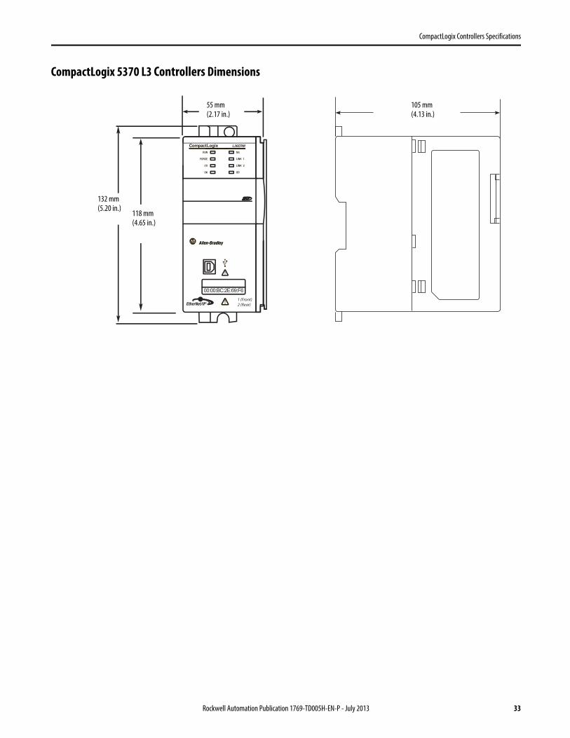
CompactLogix 5370 L3 Controllers Dimensions
1 (Front)2 (Rear)
00:00:BC:2E:69:F6
132 mm(5.20 in.)
118 mm(4.65 in.)
55 mm(2.17 in.)
105 mm(4.13 in.)
Rockwell Automation Publication 1769-TD005H-EN-P - July 2013 33
CompactLogix Controllers Specifications
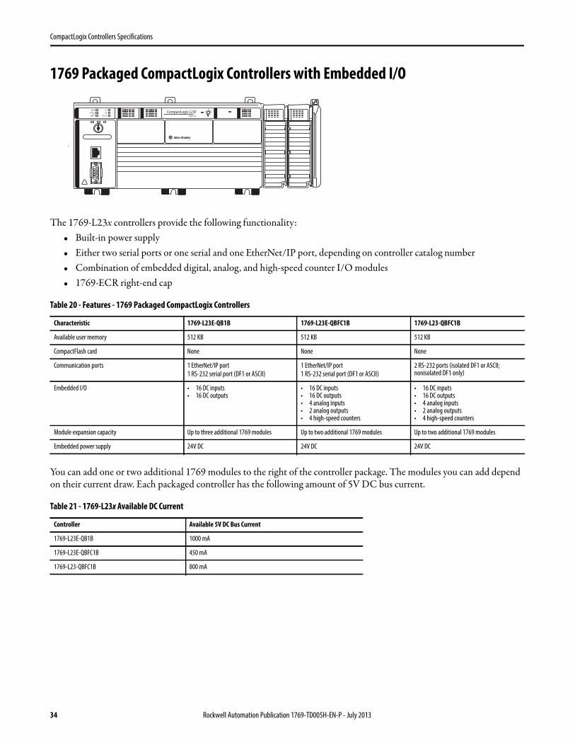
1769 Packaged CompactLogix Controllers with Embedded I/O
The 1769-L23x controllers provide the following functionality:• Built-in power supply• Either two serial ports or one serial and one EtherNet/IP port, depending on controller catalog number• Combination of embedded digital, analog, and high-speed counter I/O modules• 1769-ECR right-end cap
You can add one or two additional 1769 modules to the right of the controller package. The modules you can add depend on their current draw. Each packaged controller has the following amount of 5V DC bus current.
Table 20 - Features - 1769 Packaged CompactLogix Controllers
Characteristic 1769-L23E-QB1B 1769-L23E-QBFC1B 1769-L23-QBFC1B
Available user memory 512 KB 512 KB 512 KB
CompactFlash card None None None
Communication ports 1 EtherNet/IP port
1 RS-232 serial port (DF1 or ASCII)
1 EtherNet/IP port
1 RS-232 serial port (DF1 or ASCII)
2 RS-232 ports (isolated DF1 or ASCII; nonisolated DF1 only)
Embedded I/O • 16 DC inputs• 16 DC outputs
• 16 DC inputs• 16 DC outputs• 4 analog inputs• 2 analog outputs• 4 high-speed counters
• 16 DC inputs• 16 DC outputs• 4 analog inputs• 2 analog outputs• 4 high-speed counters
Module expansion capacity Up to three additional 1769 modules Up to two additional 1769 modules Up to two additional 1769 modules
Embedded power supply 24V DC 24V DC 24V DC
Table 21 - 1769-L23x Available DC Current
Controller Available 5V DC Bus Current
1769-L23E-QB1B 1000 mA
1769-L23E-QBFC1B 450 mA
1769-L23-QBFC1B 800 mA
34 Rockwell Automation Publication 1769-TD005H-EN-P - July 2013
CompactLogix Controllers Specifications
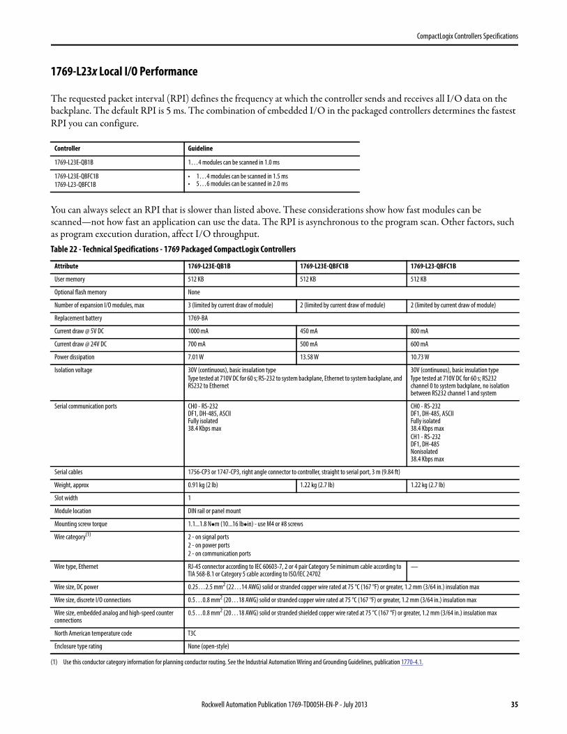
1769-L23x Local I/O Performance
The requested packet interval (RPI) defines the frequency at which the controller sends and receives all I/O data on the backplane. The default RPI is 5 ms. The combination of embedded I/O in the packaged controllers determines the fastest RPI you can configure.
You can always select an RPI that is slower than listed above. These considerations show how fast modules can be scanned—not how fast an application can use the data. The RPI is asynchronous to the program scan. Other factors, such as program execution duration, affect I/O throughput.
Controller Guideline
1769-L23E-QB1B 1…4 modules can be scanned in 1.0 ms
1769-L23E-QBFC1B
1769-L23-QBFC1B
• 1…4 modules can be scanned in 1.5 ms• 5…6 modules can be scanned in 2.0 ms
Table 22 - Technical Specifications - 1769 Packaged CompactLogix Controllers
Attribute 1769-L23E-QB1B 1769-L23E-QBFC1B 1769-L23-QBFC1B
User memory 512 KB 512 KB 512 KB
Optional flash memory None
Number of expansion I/O modules, max 3 (limited by current draw of module) 2 (limited by current draw of module) 2 (limited by current draw of module)
Replacement battery 1769-BA
Current draw @ 5V DC 1000 mA 450 mA 800 mA
Current draw @ 24V DC 700 mA 500 mA 600 mA
Power dissipation 7.01 W 13.58 W 10.73 W
Isolation voltage 30V (continuous), basic insulation type
Type tested at 710V DC for 60 s; RS-232 to system backplane, Ethernet to system backplane, and RS232 to Ethernet
30V (continuous), basic insulation type
Type tested at 710V DC for 60 s; RS232 channel 0 to system backplane, no isolation between RS232 channel 1 and system
Serial communication ports CH0 - RS-232DF1, DH-485, ASCIIFully isolated38.4 Kbps max
CH0 - RS-232DF1, DH-485, ASCIIFully isolated38.4 Kbps max
CH1 - RS-232DF1, DH-485Nonisolated38.4 Kbps max
Serial cables 1756-CP3 or 1747-CP3, right angle connector to controller, straight to serial port, 3 m (9.84 ft)
Weight, approx 0.91 kg (2 lb) 1.22 kg (2.7 lb) 1.22 kg (2.7 lb)
Slot width 1
Module location DIN rail or panel mount
Mounting screw torque 1.1...1.8 Nm (10...16 lbin) - use M4 or #8 screws
Wire category(1)
(1) Use this conductor category information for planning conductor routing. See the Industrial Automation Wiring and Grounding Guidelines, publication 1770-4.1.
2 - on signal ports
2 - on power ports
2 - on communication ports
Wire type, Ethernet RJ-45 connector according to IEC 60603-7, 2 or 4 pair Category 5e minimum cable according to TIA 568-B.1 or Category 5 cable according to ISO/IEC 24702
—
Wire size, DC power 0.25…2.5 mm2 (22…14 AWG) solid or stranded copper wire rated at 75 °C (167 °F) or greater, 1.2 mm (3/64 in.) insulation max
Wire size, discrete I/O connections 0.5…0.8 mm2 (20…18 AWG) solid or stranded copper wire rated at 75 °C (167 °F) or greater, 1.2 mm (3/64 in.) insulation max
Wire size, embedded analog and high-speed counter connections
0.5…0.8 mm2 (20…18 AWG) solid or stranded shielded copper wire rated at 75 °C (167 °F) or greater, 1.2 mm (3/64 in.) insulation max
North American temperature code T3C
Enclosure type rating None (open-style)
Rockwell Automation Publication 1769-TD005H-EN-P - July 2013 35
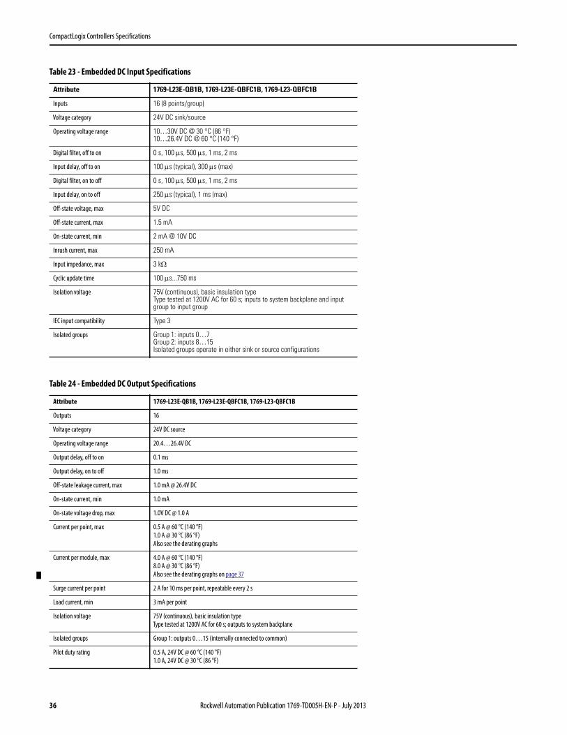
CompactLogix Controllers Specifications
Table 23 - Embedded DC Input Specifications
Attribute 1769-L23E-QB1B, 1769-L23E-QBFC1B, 1769-L23-QBFC1B
Inputs 16 (8 points/group)
Voltage category 24V DC sink/source
Operating voltage range 10…30V DC @ 30 °C (86 °F)10…26.4V DC @ 60 °C (140 °F)
Digital filter, off to on 0 s, 100 s, 500 s, 1 ms, 2 ms
Input delay, off to on 100 s (typical), 300 s (max)
Digital filter, on to off 0 s, 100 s, 500 s, 1 ms, 2 ms
Input delay, on to off 250 s (typical), 1 ms (max)
Off-state voltage, max 5V DC
Off-state current, max 1.5 mA
On-state current, min 2 mA @ 10V DC
Inrush current, max 250 mA
Input impedance, max 3 k
Cyclic update time 100 s...750 ms
Isolation voltage 75V (continuous), basic insulation typeType tested at 1200V AC for 60 s; inputs to system backplane and inputgroup to input group
IEC input compatibility Type 3
Isolated groups Group 1: inputs 0…7Group 2: inputs 8…15Isolated groups operate in either sink or source configurations
Table 24 - Embedded DC Output Specifications
Attribute 1769-L23E-QB1B, 1769-L23E-QBFC1B, 1769-L23-QBFC1B
Outputs 16
Voltage category 24V DC source
Operating voltage range 20.4…26.4V DC
Output delay, off to on 0.1 ms
Output delay, on to off 1.0 ms
Off-state leakage current, max 1.0 mA @ 26.4V DC
On-state current, min 1.0 mA
On-state voltage drop, max 1.0V DC @ 1.0 A
Current per point, max 0.5 A @ 60 °C (140 °F)
1.0 A @ 30 °C (86 °F)
Also see the derating graphs
Current per module, max 4.0 A @ 60 °C (140 °F)
8.0 A @ 30 °C (86 °F)
Also see the derating graphs on page 37
Surge current per point 2 A for 10 ms per point, repeatable every 2 s
Load current, min 3 mA per point
Isolation voltage 75V (continuous), basic insulation type
Type tested at 1200V AC for 60 s; outputs to system backplane
Isolated groups Group 1: outputs 0…15 (internally connected to common)
Pilot duty rating 0.5 A, 24V DC @ 60 °C (140 °F)
1.0 A, 24V DC @ 30 °C (86 °F)
36 Rockwell Automation Publication 1769-TD005H-EN-P - July 2013
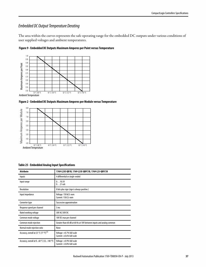
CompactLogix Controllers Specifications
Embedded DC Output Temperature Derating
The area within the curves represents the safe operating range for the embedded DC outputs under various conditions of user supplied voltages and ambient temperatures.
Table 25 - Embedded Analog Input Specifications
Attribute 1769-L23E-QB1B, 1769-L23E-QBFC1B, 1769-L23-QBFC1B
Inputs 4 differential or single-ended
Input range 0…10.5V0…21 mA
Resolution 8 bits plus sign (sign is always positive.)
Input impedance Voltage: 150 knom
Current: 150 nom
Converter type Successive approximation
Response speed per channel 5 ms
Rated working voltage 30V AC/30V DC
Common mode voltage 10V DC max per channel
Common mode rejection Greater than 60 dB at 60 Hz at 10V between inputs and analog common
Normal mode rejection ratio None
Accuracy, overall at 25 °C (77 °F)(1) Voltage: ±0.7% full scale
Current: ±0.6% full scale
Accuracy, overall at 0...60 °C (32...140 °F) Voltage: ±0.9% full scale
Current: ±0.8% full scale
4.00
4.50
5.00
5.50
6.00
6.50
7.00
7.50
8.00
30 °C (86 °F) 40 °C (104 °F) 50 °C (122 °F) 60 °C (140 °F)
0.50
0.55
0.60
0.65
0.70
0.75
0.80
0.85
0.90
0.95
1.00
30 °C (86 °F) 40 °C (104 °F) 50 °C (122 °F) 60 °C (140 °F)
Figure 2 - Embedded DC Outputs Maximum Amperes per Module versus Temperature
Figure 9 - Embedded DC Outputs Maximum Amperes per Point versus Temperature
Ambient Temperature
Ambient Temperature
Max
imum
Am
pere
s per
Poi
ntM
axim
umAm
pere
spe
rMod
ule
Rockwell Automation Publication 1769-TD005H-EN-P - July 2013 37
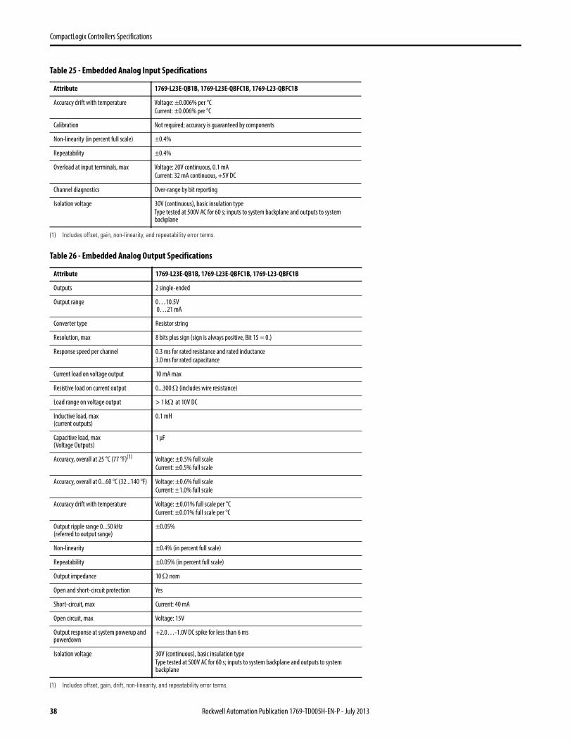
CompactLogix Controllers Specifications
Accuracy drift with temperature Voltage: ±0.006% per °C
Current: ±0.006% per °C
Calibration Not required; accuracy is guaranteed by components
Non-linearity (in percent full scale) ±0.4%
Repeatability ±0.4%
Overload at input terminals, max Voltage: 20V continuous, 0.1 mA
Current: 32 mA continuous, +5V DC
Channel diagnostics Over-range by bit reporting
Isolation voltage 30V (continuous), basic insulation type
Type tested at 500V AC for 60 s; inputs to system backplane and outputs to system backplane
(1) Includes offset, gain, non-linearity, and repeatability error terms.
Table 26 - Embedded Analog Output Specifications
Attribute 1769-L23E-QB1B, 1769-L23E-QBFC1B, 1769-L23-QBFC1B
Outputs 2 single-ended
Output range 0…10.5V 0…21 mA
Converter type Resistor string
Resolution, max 8 bits plus sign (sign is always positive, Bit 15 = 0.)
Response speed per channel 0.3 ms for rated resistance and rated inductance
3.0 ms for rated capacitance
Current load on voltage output 10 mA max
Resistive load on current output 0...300 (includes wire resistance)
Load range on voltage output > 1 kat 10V DC
Inductive load, max(current outputs)
0.1 mH
Capacitive load, max(Voltage Outputs)
1 µF
Accuracy, overall at 25 °C (77 °F)(1) Voltage: ±0.5% full scale
Current: ±0.5% full scale
Accuracy, overall at 0...60 °C (32...140 °F) Voltage: ±0.6% full scale
Current: ±1.0% full scale
Accuracy drift with temperature Voltage: ±0.01% full scale per °C
Current: ±0.01% full scale per °C
Output ripple range 0...50 kHz(referred to output range)
±0.05%
Non-linearity ±0.4% (in percent full scale)
Repeatability ±0.05% (in percent full scale)
Output impedance 10 nom
Open and short-circuit protection Yes
Short-circuit, max Current: 40 mA
Open circuit, max Voltage: 15V
Output response at system powerup and powerdown
+2.0…-1.0V DC spike for less than 6 ms
Isolation voltage 30V (continuous), basic insulation type
Type tested at 500V AC for 60 s; inputs to system backplane and outputs to system backplane
(1) Includes offset, gain, drift, non-linearity, and repeatability error terms.
Table 25 - Embedded Analog Input Specifications
Attribute 1769-L23E-QB1B, 1769-L23E-QBFC1B, 1769-L23-QBFC1B
38 Rockwell Automation Publication 1769-TD005H-EN-P - July 2013
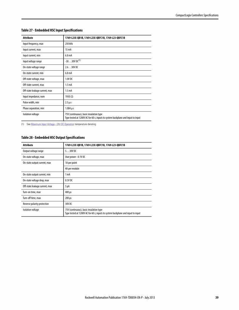
CompactLogix Controllers Specifications
Table 27 - Embedded HSC Input Specifications
Attribute 1769-L23E-QB1B, 1769-L23E-QBFC1B, 1769-L23-QBFC1B
Input frequency, max 250 kHz
Input current, max 15 mA
Input current, min 6.8 mA
Input voltage range -30…30V DC(1)
(1) See Maximum Input Voltage - 24V DC Operation temperature derating.
On-state voltage range 2.6…30V DC
On-state current, min 6.8 mA
Off-state voltage, max 1.0V DC
Off-state current, max 1.5 mA
Off-state leakage current, max 1.5 mA
Input impedance, nom 1950
Pulse width, min 2.5 s
Phase separation, min 1.084 s
Isolation voltage 75V (continuous), basic insulation type
Type tested at 1200V AC for 60 s; inputs to system backplane and input to input
Table 28 - Embedded HSC Output Specifications
Attribute 1769-L23E-QB1B, 1769-L23E-QBFC1B, 1769-L23-QBFC1B
Output voltage range 5…30V DC
On-state voltage, max User power - 0.1V DC
On-state output current, max 1A per point
4A per module
On-state output current, min 1 mA
On-state voltage drop, max 0.5V DC
Off-state leakage current, max 5 µA
Turn-on time, max 400 µs
Turn-off time, max 200 µs
Reverse polarity protection 30V DC
Isolation voltage 75V (continuous), basic insulation type
Type tested at 1200V AC for 60 s; inputs to system backplane and input to input
Rockwell Automation Publication 1769-TD005H-EN-P - July 2013 39
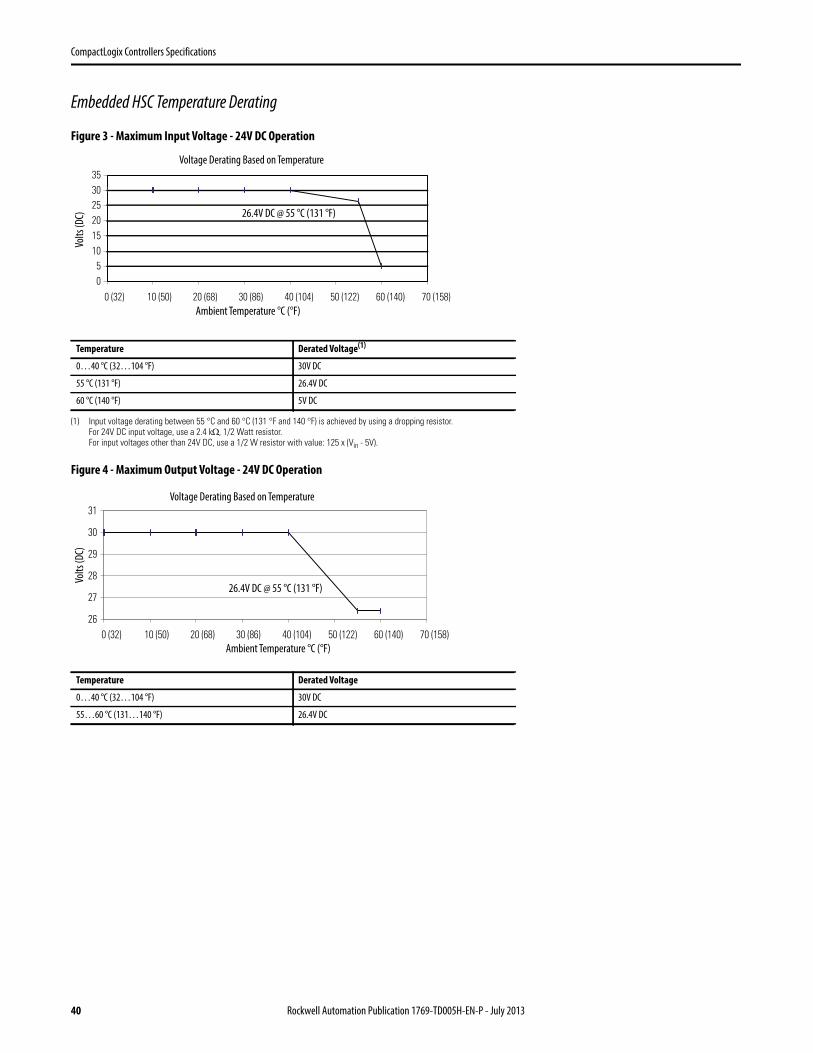
CompactLogix Controllers Specifications
Embedded HSC Temperature Derating
Figure 3 - Maximum Input Voltage - 24V DC Operation
Figure 4 - Maximum Output Voltage - 24V DC Operation
Temperature Derated Voltage(1)
(1) Input voltage derating between 55 °C and 60 °C (131 °F and 140 °F) is achieved by using a dropping resistor.For 24V DC input voltage, use a 2.4 k, 1/2 Watt resistor.For input voltages other than 24V DC, use a 1/2 W resistor with value: 125 x (Vin - 5V).
0…40 °C (32…104 °F) 30V DC
55 °C (131 °F) 26.4V DC
60 °C (140 °F) 5V DC
Temperature Derated Voltage
0…40 °C (32…104 °F) 30V DC
55…60 °C (131…140 °F) 26.4V DC
05
101520253035
0 (32) 10 (50) 20 (68) 30 (86) 40 (104) 50 (122) 60 (140) 70 (158)
Voltage Derating Based on Temperature
Ambient Temperature °C (°F)
Volts
(DC) 26.4V DC @ 55 °C (131 °F)
26
27
28
29
30
31
0 (32) 10 (50) 20 (68) 30 (86) 40 (104) 50 (122) 60 (140) 70 (158)
Voltage Derating Based on Temperature
Volts
(DC)
Ambient Temperature °C (°F)
26.4V DC @ 55 °C (131 °F)
40 Rockwell Automation Publication 1769-TD005H-EN-P - July 2013

CompactLogix Controllers Specifications
Figure 5 - Maximum Output Current per Point - 5V DC Operation
Figure 6 - Maximum Output Current per Module - 5V DC Operation
Figure 7 - Maximum Output Current per Point - 24V DC Operation
Temperature Derated Current
0…40 °C (32…104 °F) 1 A
60 °C (140 °F) 0.5 A
Temperature Derated Current
0…40 °C (32…104 °F) 4 A
60 °C (140 °F) 2 A
Temperature Derated Current
0...40 °C (32...104 °F) 1 A
55 °C (131 °F) 0.5 A
60 °C (140 °F) 0.25 A
0
0.5
1
1.5
0 (32) 10 (50) 20 (68) 30 (86) 40 (104) 50 (122) 60 (140) 70 (158)
Current Derating Based on Temperature
Ambient Temperature °C (°F)
Curr
ent p
er P
oint
(A)
0.5 A at 60 °C (131 °F)
0
1
2
3
4
5
0 (32) 10 (50) 20 (68) 30 (86) 40 (104) 50 (122) 60 (140) 70 (158)
Current Derating Based on Temperature
Ambient Temperature °C (°F)
Curr
ent p
er M
odul
e (A
)
2 A at 60 °C (131 °F)
0
0.5
1
1.5
0 (32) 10 (50) 20 (68) 30 (86) 40 (104) 50 (122) 60 (140) 70 (158)
Current Derating Based on Temperature
Ambient Temperature °C (°F)
Curr
ent p
er P
oint
(A)
0.25 A at 60 °C (131 °F)
Rockwell Automation Publication 1769-TD005H-EN-P - July 2013 41
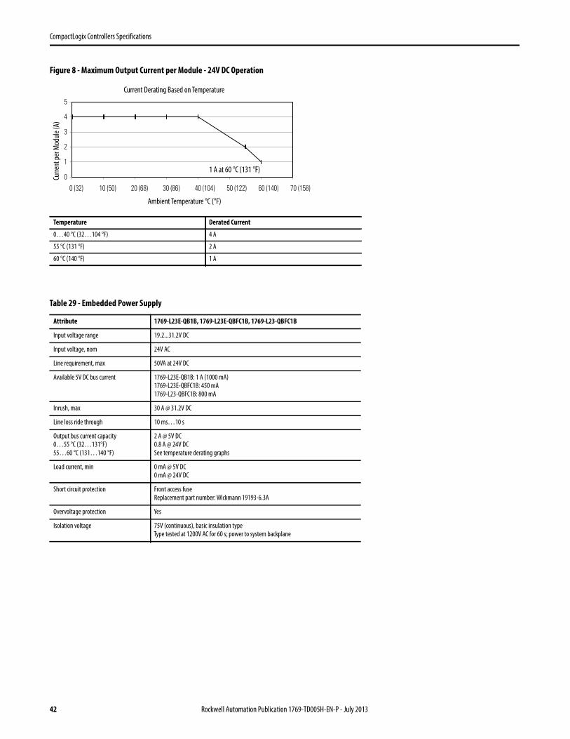
CompactLogix Controllers Specifications
Figure 8 - Maximum Output Current per Module - 24V DC Operation
Temperature Derated Current
0…40 °C (32…104 °F) 4 A
55 °C (131 °F) 2 A
60 °C (140 °F) 1 A
Table 29 - Embedded Power Supply
Attribute 1769-L23E-QB1B, 1769-L23E-QBFC1B, 1769-L23-QBFC1B
Input voltage range 19.2...31.2V DC
Input voltage, nom 24V AC
Line requirement, max 50VA at 24V DC
Available 5V DC bus current 1769-L23E-QB1B: 1 A (1000 mA)
1769-L23E-QBFC1B: 450 mA
1769-L23-QBFC1B: 800 mA
Inrush, max 30 A @ 31.2V DC
Line loss ride through 10 ms…10 s
Output bus current capacity
0…55 °C (32…131°F)
55…60 °C (131…140 °F)
2 A @ 5V DC
0.8 A @ 24V DC
See temperature derating graphs
Load current, min 0 mA @ 5V DC
0 mA @ 24V DC
Short circuit protection Front access fuse
Replacement part number: Wickmann 19193-6.3A
Overvoltage protection Yes
Isolation voltage 75V (continuous), basic insulation type
Type tested at 1200V AC for 60 s; power to system backplane
0
1
2
3
4
5
0 (32) 10 (50) 20 (68) 30 (86) 40 (104) 50 (122) 60 (140) 70 (158)
Current Derating Based on Temperature
Ambient Temperature °C (°F)
Curr
ent p
er M
odul
e (A
)
1 A at 60 °C (131 °F)
42 Rockwell Automation Publication 1769-TD005H-EN-P - July 2013
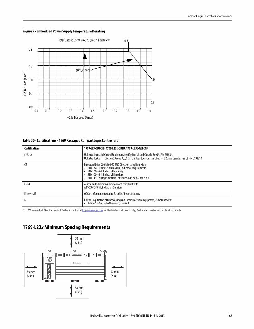
CompactLogix Controllers Specifications
Figure 9 - Embedded Power Supply Temperature Derating
1769-L23x Minimum Spacing Requirements
Table 30 - Certifications - 1769 Packaged CompactLogix Controllers
Certification(1)
(1) When marked. See the Product Certification link at http://www.ab.com for Declarations of Conformity, Certificates, and other certification details.
1769-L23-QBFC1B, 1769-L23E-QB1B, 1769-L23E-QBFC1B
c-UL-us UL Listed Industrial Control Equipment, certified for US and Canada. See UL File E65584.
UL Listed for Class I, Division 2 Group A,B,C,D Hazardous Locations, certified for U.S. and Canada. See UL File E194810.
CE European Union 2004/108/EC EMC Directive, compliant with:• EN 61326-1; Meas./Control/Lab., Industrial Requirements• EN 61000-6-2; Industrial Immunity• EN 61000-6-4; Industrial Emissions• EN 61131-2; Programmable Controllers (Clause 8, Zone A & B)
C-Tick Australian Radiocommunications Act, compliant with:AS/NZS CISPR 11; Industrial Emissions
EtherNet/IP ODVA conformance tested to EtherNet/IP specifications
KC Korean Registration of Broadcasting and Communications Equipment, compliant with:• Article 58-2 of Radio Waves Act, Clause 3
+24V Bus Load (Amps)
+5V
Bus
Loa
d (A
mps
)
0.0 0.1 0.2 0.3 0.4 0.5 0.6 0.7 0.8 0.9 1.0
2.0
1.5
1.0
0.5
0.0
0.8
1.0
0.2
60 °C (140 °F)
Total Output: 29 W @ 60 °C (140 °F) or Below
50 mm(2 in.)
50 mm(2 in.)
50 mm(2 in.)
50 mm(2 in.)
Rockwell Automation Publication 1769-TD005H-EN-P - July 2013 43
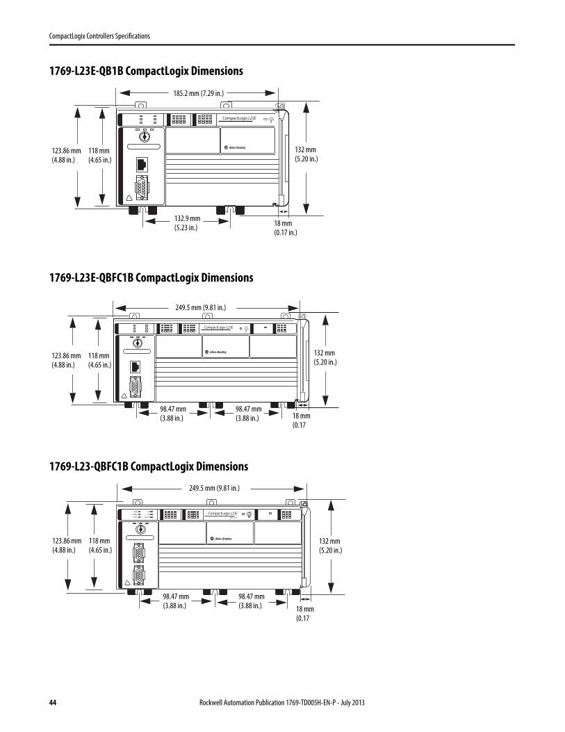
CompactLogix Controllers Specifications
1769-L23E-QB1B CompactLogix Dimensions
1769-L23E-QBFC1B CompactLogix Dimensions
1769-L23-QBFC1B CompactLogix Dimensions
185.2 mm (7.29 in.)
132.9 mm (5.23 in.)
18 mm (0.17 in.)
132 mm (5.20 in.)
118 mm (4.65 in.)
123.86 mm (4.88 in.)
249.5 mm (9.81 in.)
98.47 mm (3.88 in.) 18 mm
(0.17
132 mm (5.20 in.)
118 mm (4.65 in.)
123.86 mm (4.88 in.)
98.47 mm (3.88 in.)
249.5 mm (9.81 in.)
98.47 mm (3.88 in.) 18 mm
(0.17
132 mm (5.20 in.)
118 mm (4.65 in.)
123.86 mm (4.88 in.)
98.47 mm (3.88 in.)
44 Rockwell Automation Publication 1769-TD005H-EN-P - July 2013
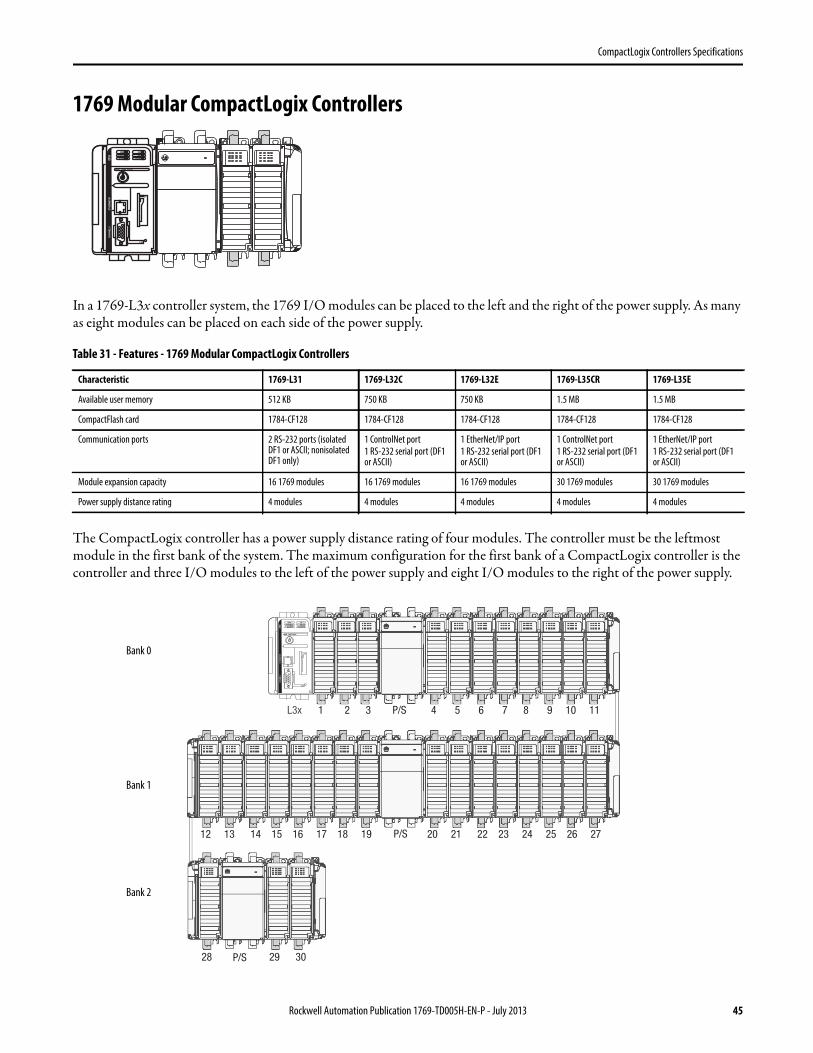
CompactLogix Controllers Specifications
1769 Modular CompactLogix Controllers
In a 1769-L3x controller system, the 1769 I/O modules can be placed to the left and the right of the power supply. As many as eight modules can be placed on each side of the power supply.
The CompactLogix controller has a power supply distance rating of four modules. The controller must be the leftmost module in the first bank of the system. The maximum configuration for the first bank of a CompactLogix controller is the controller and three I/O modules to the left of the power supply and eight I/O modules to the right of the power supply.
Table 31 - Features - 1769 Modular CompactLogix Controllers
Characteristic 1769-L31 1769-L32C 1769-L32E 1769-L35CR 1769-L35E
Available user memory 512 KB 750 KB 750 KB 1.5 MB 1.5 MB
CompactFlash card 1784-CF128 1784-CF128 1784-CF128 1784-CF128 1784-CF128
Communication ports 2 RS-232 ports (isolated DF1 or ASCII; nonisolated DF1 only)
1 ControlNet port
1 RS-232 serial port (DF1 or ASCII)
1 EtherNet/IP port
1 RS-232 serial port (DF1 or ASCII)
1 ControlNet port
1 RS-232 serial port (DF1 or ASCII)
1 EtherNet/IP port
1 RS-232 serial port (DF1 or ASCII)
Module expansion capacity 16 1769 modules 16 1769 modules 16 1769 modules 30 1769 modules 30 1769 modules
Power supply distance rating 4 modules 4 modules 4 modules 4 modules 4 modules
Bank 0
Bank 1
Bank 2
Rockwell Automation Publication 1769-TD005H-EN-P - July 2013 45
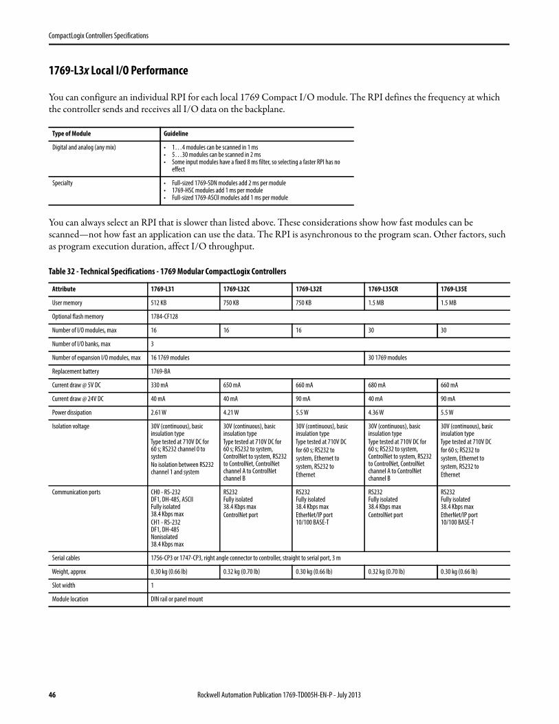
CompactLogix Controllers Specifications
1769-L3x Local I/O Performance
You can configure an individual RPI for each local 1769 Compact I/O module. The RPI defines the frequency at which the controller sends and receives all I/O data on the backplane.
You can always select an RPI that is slower than listed above. These considerations show how fast modules can be scanned—not how fast an application can use the data. The RPI is asynchronous to the program scan. Other factors, such as program execution duration, affect I/O throughput.
Type of Module Guideline
Digital and analog (any mix) • 1…4 modules can be scanned in 1 ms• 5…30 modules can be scanned in 2 ms• Some input modules have a fixed 8 ms filter, so selecting a faster RPI has no
effect
Specialty • Full-sized 1769-SDN modules add 2 ms per module• 1769-HSC modules add 1 ms per module• Full-sized 1769-ASCII modules add 1 ms per module
Table 32 - Technical Specifications - 1769 Modular CompactLogix Controllers
Attribute 1769-L31 1769-L32C 1769-L32E 1769-L35CR 1769-L35E
User memory 512 KB 750 KB 750 KB 1.5 MB 1.5 MB
Optional flash memory 1784-CF128
Number of I/O modules, max 16 16 16 30 30
Number of I/O banks, max 3
Number of expansion I/O modules, max 16 1769 modules 30 1769 modules
Replacement battery 1769-BA
Current draw @ 5V DC 330 mA 650 mA 660 mA 680 mA 660 mA
Current draw @ 24V DC 40 mA 40 mA 90 mA 40 mA 90 mA
Power dissipation 2.61 W 4.21 W 5.5 W 4.36 W 5.5 W
Isolation voltage 30V (continuous), basic insulation type
Type tested at 710V DC for 60 s; RS232 channel 0 to system
No isolation between RS232 channel 1 and system
30V (continuous), basic insulation type
Type tested at 710V DC for 60 s; RS232 to system, ControlNet to system, RS232 to ControlNet, ControlNet channel A to ControlNet channel B
30V (continuous), basic insulation type
Type tested at 710V DC
for 60 s; RS232 to
system, Ethernet to
system, RS232 to
Ethernet
30V (continuous), basic insulation type
Type tested at 710V DC for 60 s; RS232 to system, ControlNet to system, RS232 to ControlNet, ControlNet channel A to ControlNet channel B
30V (continuous), basic insulation type
Type tested at 710V DC
for 60 s; RS232 to
system, Ethernet to
system, RS232 to
Ethernet
Communication ports CH0 - RS-232DF1, DH-485, ASCIIFully isolated38.4 Kbps max
CH1 - RS-232DF1, DH-485Nonisolated38.4 Kbps max
RS232Fully isolated38.4 Kbps max
ControlNet port
RS232Fully isolated38.4 Kbps max
EtherNet/IP port10/100 BASE-T
RS232Fully isolated38.4 Kbps max
ControlNet port
RS232Fully isolated38.4 Kbps max
EtherNet/IP port10/100 BASE-T
Serial cables 1756-CP3 or 1747-CP3, right angle connector to controller, straight to serial port, 3 m
Weight, approx 0.30 kg (0.66 lb) 0.32 kg (0.70 lb) 0.30 kg (0.66 lb) 0.32 kg (0.70 lb) 0.30 kg (0.66 lb)
Slot width 1
Module location DIN rail or panel mount
46 Rockwell Automation Publication 1769-TD005H-EN-P - July 2013
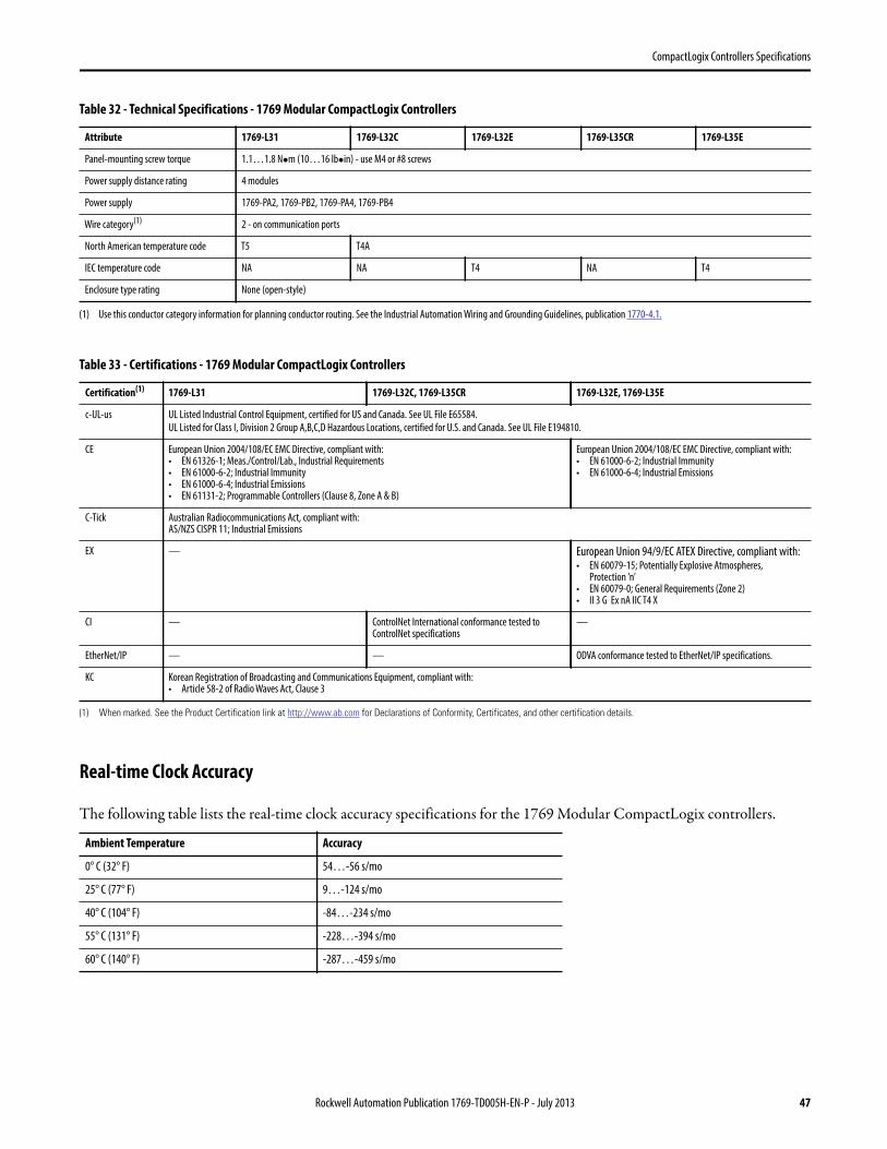
CompactLogix Controllers Specifications
Real-time Clock Accuracy
The following table lists the real-time clock accuracy specifications for the 1769 Modular CompactLogix controllers.
Panel-mounting screw torque 1.1…1.8 Nm (10…16 lbin) - use M4 or #8 screws
Power supply distance rating 4 modules
Power supply 1769-PA2, 1769-PB2, 1769-PA4, 1769-PB4
Wire category(1) 2 - on communication ports
North American temperature code T5 T4A
IEC temperature code NA NA T4 NA T4
Enclosure type rating None (open-style)
(1) Use this conductor category information for planning conductor routing. See the Industrial Automation Wiring and Grounding Guidelines, publication 1770-4.1.
Table 33 - Certifications - 1769 Modular CompactLogix Controllers
Certification(1)
(1) When marked. See the Product Certification link at http://www.ab.com for Declarations of Conformity, Certificates, and other certification details.
1769-L31 1769-L32C, 1769-L35CR 1769-L32E, 1769-L35E
c-UL-us UL Listed Industrial Control Equipment, certified for US and Canada. See UL File E65584.
UL Listed for Class I, Division 2 Group A,B,C,D Hazardous Locations, certified for U.S. and Canada. See UL File E194810.
CE European Union 2004/108/EC EMC Directive, compliant with:• EN 61326-1; Meas./Control/Lab., Industrial Requirements• EN 61000-6-2; Industrial Immunity• EN 61000-6-4; Industrial Emissions• EN 61131-2; Programmable Controllers (Clause 8, Zone A & B)
European Union 2004/108/EC EMC Directive, compliant with:• EN 61000-6-2; Industrial Immunity• EN 61000-6-4; Industrial Emissions
C-Tick Australian Radiocommunications Act, compliant with:AS/NZS CISPR 11; Industrial Emissions
EX — European Union 94/9/EC ATEX Directive, compliant with:• EN 60079-15; Potentially Explosive Atmospheres,
Protection ’n’• EN 60079-0; General Requirements (Zone 2)• II 3 G Ex nA IIC T4 X
CI — ControlNet International conformance tested to ControlNet specifications
—
EtherNet/IP — — ODVA conformance tested to EtherNet/IP specifications.
KC Korean Registration of Broadcasting and Communications Equipment, compliant with:• Article 58-2 of Radio Waves Act, Clause 3
Ambient Temperature Accuracy
0° C (32° F) 54…-56 s/mo
25° C (77° F) 9…-124 s/mo
40° C (104° F) -84…-234 s/mo
55° C (131° F) -228…-394 s/mo
60° C (140° F) -287…-459 s/mo
Table 32 - Technical Specifications - 1769 Modular CompactLogix Controllers
Attribute 1769-L31 1769-L32C 1769-L32E 1769-L35CR 1769-L35E
Rockwell Automation Publication 1769-TD005H-EN-P - July 2013 47
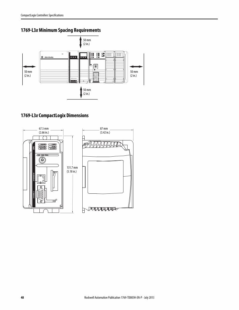
CompactLogix Controllers Specifications
1769-L3x Minimum Spacing Requirements
1769-L3x CompactLogix Dimensions
50 mm(2 in.)
50 mm(2 in.)
50 mm(2 in.)
50 mm(2 in.)
67.5 mm(2.66 in.)
87 mm(3.42 in.)
131.7 mm(5.18 in.)
48 Rockwell Automation Publication 1769-TD005H-EN-P - July 2013
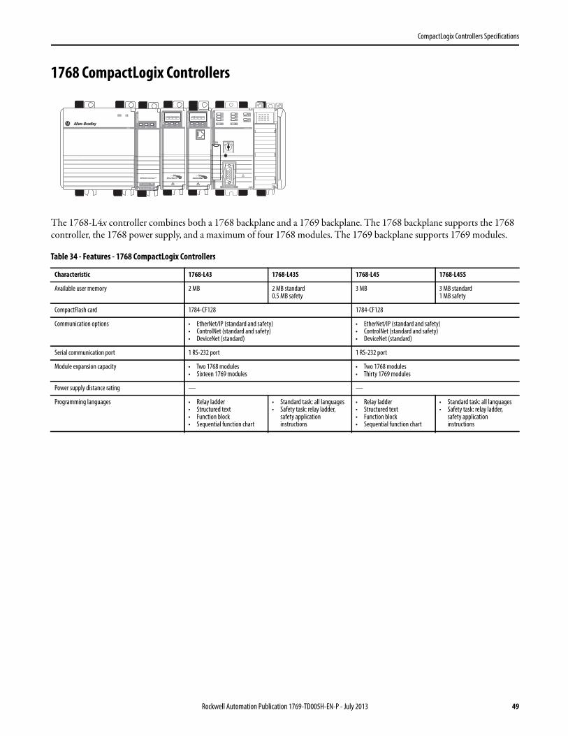
CompactLogix Controllers Specifications
1768 CompactLogix Controllers
The 1768-L4x controller combines both a 1768 backplane and a 1769 backplane. The 1768 backplane supports the 1768 controller, the 1768 power supply, and a maximum of four 1768 modules. The 1769 backplane supports 1769 modules.
Table 34 - Features - 1768 CompactLogix Controllers
Characteristic 1768-L43 1768-L43S 1768-L45 1768-L45S
Available user memory 2 MB 2 MB standard0.5 MB safety
3 MB 3 MB standard1 MB safety
CompactFlash card 1784-CF128 1784-CF128
Communication options • EtherNet/IP (standard and safety)• ControlNet (standard and safety)• DeviceNet (standard)
• EtherNet/IP (standard and safety)• ControlNet (standard and safety)• DeviceNet (standard)
Serial communication port 1 RS-232 port 1 RS-232 port
Module expansion capacity • Two 1768 modules• Sixteen 1769 modules
• Two 1768 modules• Thirty 1769 modules
Power supply distance rating — —
Programming languages • Relay ladder• Structured text• Function block• Sequential function chart
• Standard task: all languages• Safety task: relay ladder,
safety application instructions
• Relay ladder• Structured text• Function block• Sequential function chart
• Standard task: all languages• Safety task: relay ladder,
safety application instructions
Rockwell Automation Publication 1769-TD005H-EN-P - July 2013 49
CompactLogix Controllers Specifications
Compact GuardLogix Safety System
The Compact GuardLogix controller is a 1768-L4xS CompactLogix controller that provides safety control to achieve SIL 3/PLe according to ISO 13849. A major benefit of this system is that it’s still a single project, safety and standard together.
During development, safety and standard have the same rules. The following are allowed:• Multiple programmers• Online editing• Forcing
Once the project is tested and ready for final validation, you apply the safety application signature and safety-lock the application to set the safety task to a SIL 3 integrity level, which is then enforced by the GuardLogix controller. When safety memory is locked and protected, the safety logic can't be modified and all safety functions operate with SIL 3 integrity. On the standard side of the GuardLogix controller, all functions operate like a regular Logix controller. Thus online editing, forcing, and other activities are all allowed.
With this level of integration, safety memory can be read by standard logic and external devices, like HMIs or other controllers, eliminating the need to condition safety memory for use elsewhere. The result is easy system-wide integration
and the ability to display safety status on displays or marquees. Use Guard I/O™ modules for field device connectivity. For safety interlocking between GuardLogix controllers use Ethernet or ControlNet networks. Multiple GuardLogix controllers can share safety data for zone to zone interlocking, or a single GuardLogix controller can use remote distributed safety I/O between different cells/areas.
Application Description
SIL 1, 2, 3 The Compact GuardLogix controller system is type-approved and certified for use in safety applications up to and including SIL 3 according to IEC 61508, and applications up to and including PLe/Cat.4 according to ISO 13849-1. For more information, see the following:
• GuardLogix Controllers Systems Safety Reference Manual, publication 1756-RM093
• Compact GuardLogix Controllers User Manual, publication 1768-UM002
• GuardLogix Safety Application Instruction Set Reference Manual, publication 1756-RM095
50 Rockwell Automation Publication 1769-TD005H-EN-P - July 2013
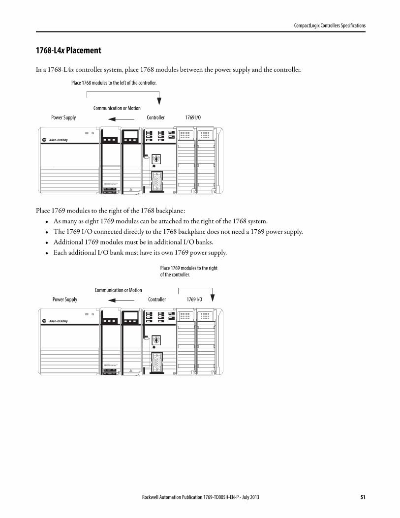
CompactLogix Controllers Specifications
1768-L4x Placement
In a 1768-L4x controller system, place 1768 modules between the power supply and the controller.
Place 1769 modules to the right of the 1768 backplane:• As many as eight 1769 modules can be attached to the right of the 1768 system.• The 1769 I/O connected directly to the 1768 backplane does not need a 1769 power supply.• Additional 1769 modules must be in additional I/O banks.• Each additional I/O bank must have its own 1769 power supply.
Place 1768 modules to the left of the controller.
Communication or Motion
Power Supply Controller 1769 I/O
Communication or Motion
Power Supply Controller 1769 I/O
Place 1769 modules to the right of the controller.
Rockwell Automation Publication 1769-TD005H-EN-P - July 2013 51
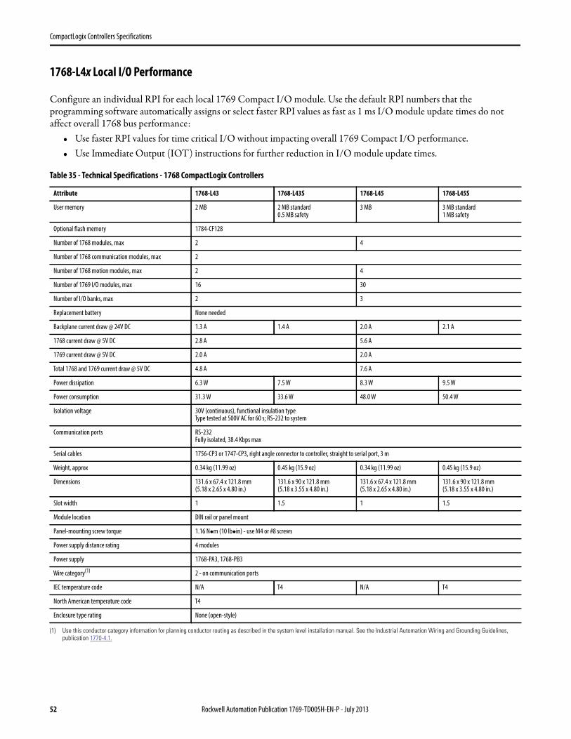
CompactLogix Controllers Specifications
1768-L4x Local I/O Performance
Configure an individual RPI for each local 1769 Compact I/O module. Use the default RPI numbers that the programming software automatically assigns or select faster RPI values as fast as 1 ms I/O module update times do not affect overall 1768 bus performance:
• Use faster RPI values for time critical I/O without impacting overall 1769 Compact I/O performance.• Use Immediate Output (IOT) instructions for further reduction in I/O module update times.
Table 35 - Technical Specifications - 1768 CompactLogix Controllers
Attribute 1768-L43 1768-L43S 1768-L45 1768-L45S
User memory 2 MB 2 MB standard0.5 MB safety
3 MB 3 MB standard1 MB safety
Optional flash memory 1784-CF128
Number of 1768 modules, max 2 4
Number of 1768 communication modules, max 2
Number of 1768 motion modules, max 2 4
Number of 1769 I/O modules, max 16 30
Number of I/O banks, max 2 3
Replacement battery None needed
Backplane current draw @ 24V DC 1.3 A 1.4 A 2.0 A 2.1 A
1768 current draw @ 5V DC 2.8 A 5.6 A
1769 current draw @ 5V DC 2.0 A 2.0 A
Total 1768 and 1769 current draw @ 5V DC 4.8 A 7.6 A
Power dissipation 6.3 W 7.5 W 8.3 W 9.5 W
Power consumption 31.3 W 33.6 W 48.0 W 50.4 W
Isolation voltage 30V (continuous), functional insulation typeType tested at 500V AC for 60 s; RS-232 to system
Communication ports RS-232Fully isolated, 38.4 Kbps max
Serial cables 1756-CP3 or 1747-CP3, right angle connector to controller, straight to serial port, 3 m
Weight, approx 0.34 kg (11.99 oz) 0.45 kg (15.9 oz) 0.34 kg (11.99 oz) 0.45 kg (15.9 oz)
Dimensions 131.6 x 67.4 x 121.8 mm(5.18 x 2.65 x 4.80 in.)
131.6 x 90 x 121.8 mm(5.18 x 3.55 x 4.80 in.)
131.6 x 67.4 x 121.8 mm(5.18 x 2.65 x 4.80 in.)
131.6 x 90 x 121.8 mm(5.18 x 3.55 x 4.80 in.)
Slot width 1 1.5 1 1.5
Module location DIN rail or panel mount
Panel-mounting screw torque 1.16 Nm (10 lbin) - use M4 or #8 screws
Power supply distance rating 4 modules
Power supply 1768-PA3, 1768-PB3
Wire category(1)
(1) Use this conductor category information for planning conductor routing as described in the system level installation manual. See the Industrial Automation Wiring and Grounding Guidelines,publication 1770-4.1.
2 - on communication ports
IEC temperature code N/A T4 N/A T4
North American temperature code T4
Enclosure type rating None (open-style)
52 Rockwell Automation Publication 1769-TD005H-EN-P - July 2013
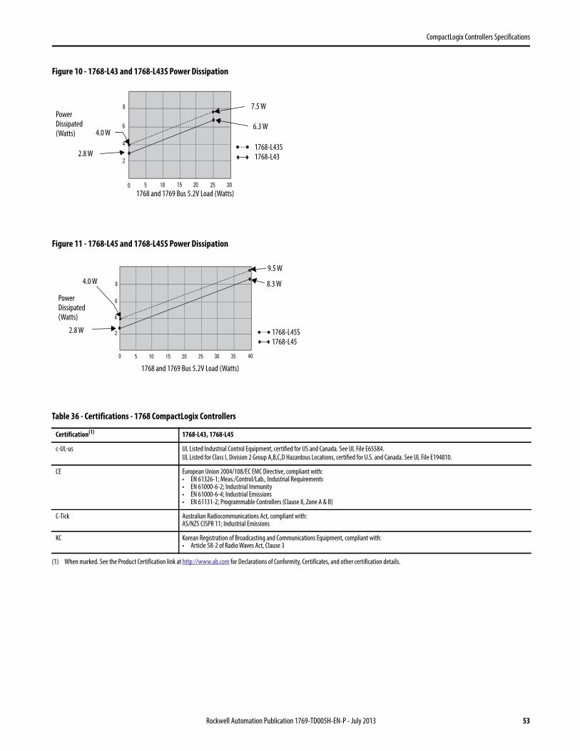
CompactLogix Controllers Specifications
Figure 10 - 1768-L43 and 1768-L43S Power Dissipation
Figure 11 - 1768-L45 and 1768-L45S Power Dissipation
Table 36 - Certifications - 1768 CompactLogix Controllers
Certification(1)
(1) When marked. See the Product Certification link at http://www.ab.com for Declarations of Conformity, Certificates, and other certification details.
1768-L43, 1768-L45
c-UL-us UL Listed Industrial Control Equipment, certified for US and Canada. See UL File E65584.
UL Listed for Class I, Division 2 Group A,B,C,D Hazardous Locations, certified for U.S. and Canada. See UL File E194810.
CE European Union 2004/108/EC EMC Directive, compliant with:• EN 61326-1; Meas./Control/Lab., Industrial Requirements• EN 61000-6-2; Industrial Immunity• EN 61000-6-4; Industrial Emissions• EN 61131-2; Programmable Controllers (Clause 8, Zone A & B)
C-Tick Australian Radiocommunications Act, compliant with:AS/NZS CISPR 11; Industrial Emissions
KC Korean Registration of Broadcasting and Communications Equipment, compliant with:• Article 58-2 of Radio Waves Act, Clause 3
0 5 10 15 20 25
6
8
30
4
�
�
��2
6.3 W
2.8 W
Power Dissipated (Watts)
1768 and 1769 Bus 5.2V Load (Watts)
7.5 W
4.0 W
1768-L43S
1768-L43
0 5 10 15 20 25
6
8
30
4
35
2
40
�
�
��2.8 W
8.3 W
Power Dissipated (Watts)
1768 and 1769 Bus 5.2V Load (Watts)
9.5 W
4.0 W
1768-L45S
1768-L45
Rockwell Automation Publication 1769-TD005H-EN-P - July 2013 53
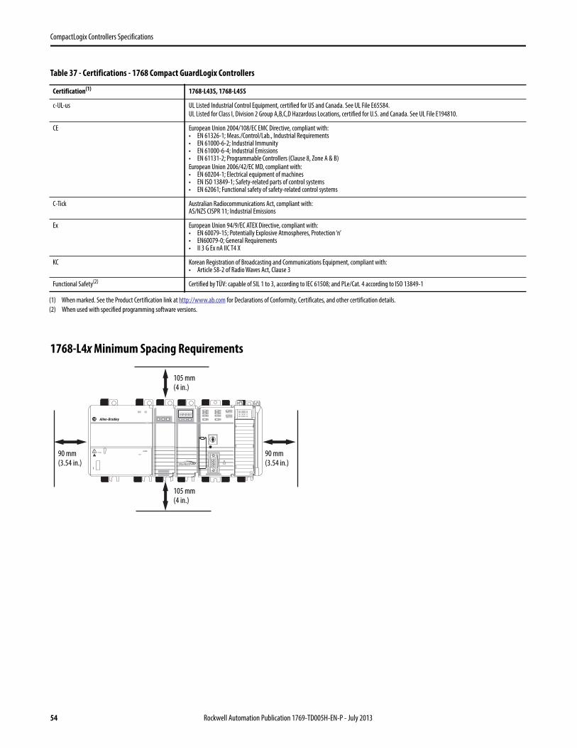
CompactLogix Controllers Specifications
1768-L4x Minimum Spacing Requirements
Table 37 - Certifications - 1768 Compact GuardLogix Controllers
Certification(1)
(1) When marked. See the Product Certification link at http://www.ab.com for Declarations of Conformity, Certificates, and other certification details.
1768-L43S, 1768-L45S
c-UL-us UL Listed Industrial Control Equipment, certified for US and Canada. See UL File E65584.
UL Listed for Class I, Division 2 Group A,B,C,D Hazardous Locations, certified for U.S. and Canada. See UL File E194810.
CE European Union 2004/108/EC EMC Directive, compliant with:• EN 61326-1; Meas./Control/Lab., Industrial Requirements• EN 61000-6-2; Industrial Immunity• EN 61000-6-4; Industrial Emissions• EN 61131-2; Programmable Controllers (Clause 8, Zone A & B)
European Union 2006/42/EC MD, compliant with:• EN 60204-1; Electrical equipment of machines• EN ISO 13849-1; Safety-related parts of control systems• EN 62061; Functional safety of safety-related control systems
C-Tick Australian Radiocommunications Act, compliant with:AS/NZS CISPR 11; Industrial Emissions
Ex European Union 94/9/EC ATEX Directive, compliant with: • EN 60079-15; Potentially Explosive Atmospheres, Protection ‘n’• EN60079-0; General Requirements• II 3 G Ex nA IIC T4 X
KC Korean Registration of Broadcasting and Communications Equipment, compliant with:• Article 58-2 of Radio Waves Act, Clause 3
Functional Safety(2)
(2) When used with specified programming software versions.
Certified by TÜV: capable of SIL 1 to 3, according to IEC 61508; and PLe/Cat. 4 according to ISO 13849-1
105 mm(4 in.)
90 mm(3.54 in.)
90 mm(3.54 in.)
105 mm(4 in.)
54 Rockwell Automation Publication 1769-TD005H-EN-P - July 2013
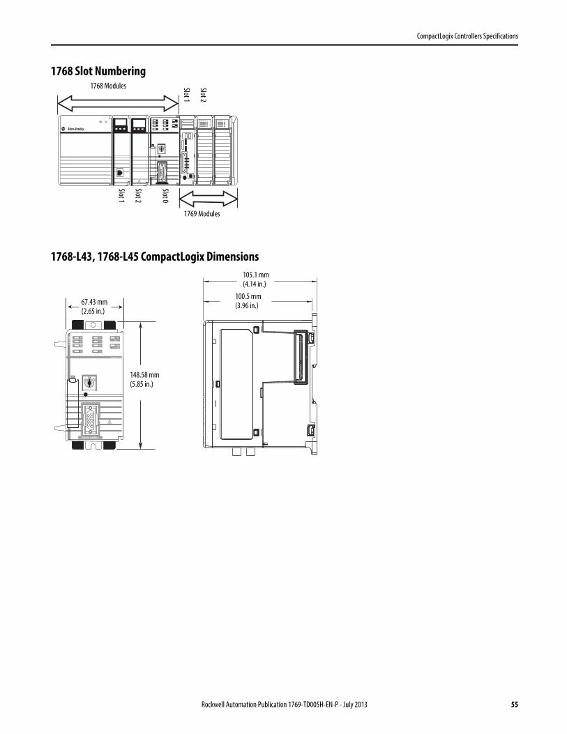
CompactLogix Controllers Specifications
1768 Slot Numbering
1768-L43, 1768-L45 CompactLogix Dimensions
1768 Modules
1769 Modules
Slot 1
Slot 2
Slot 1
Slot 2
Slot 0
67.43 mm(2.65 in.)
105.1 mm(4.14 in.)
100.5 mm(3.96 in.)
148.58 mm(5.85 in.)
Rockwell Automation Publication 1769-TD005H-EN-P - July 2013 55
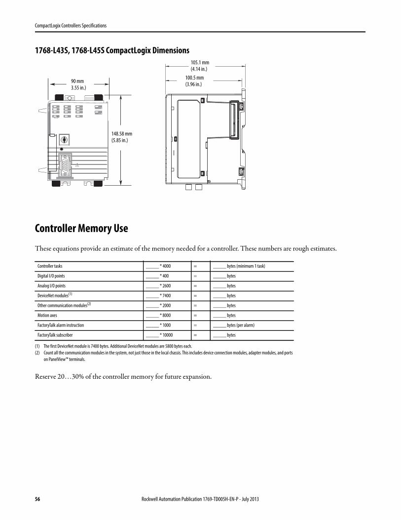
CompactLogix Controllers Specifications
1768-L43S, 1768-L45S CompactLogix Dimensions
Controller Memory Use
These equations provide an estimate of the memory needed for a controller. These numbers are rough estimates.
Reserve 20…30% of the controller memory for future expansion.
Controller tasks _____ * 4000 = _____ bytes (minimum 1 task)
Digital I/O points _____ * 400 = _____ bytes
Analog I/O points _____ * 2600 = _____ bytes
DeviceNet modules(1)
(1) The first DeviceNet module is 7400 bytes. Additional DeviceNet modules are 5800 bytes each.
_____ * 7400 = _____ bytes
Other communication modules(2)
(2) Count all the communication modules in the system, not just those in the local chassis. This includes device connection modules, adapter modules, and ports
on PanelView™ terminals.
_____ * 2000 = _____ bytes
Motion axes _____ * 8000 = _____ bytes
FactoryTalk alarm instruction _____ * 1000 = _____ bytes (per alarm)
FactoryTalk subscriber _____ * 10000 = _____ bytes
90 mm3.55 in.)
105.1 mm(4.14 in.)
100.5 mm(3.96 in.)
148.58 mm(5.85 in.)
56 Rockwell Automation Publication 1769-TD005H-EN-P - July 2013
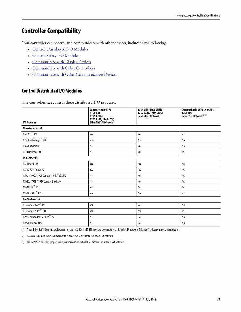
CompactLogix Controllers Specifications
Controller Compatibility
Your controller can control and communicate with other devices, including the following:• Control Distributed I/O Modules• Control Safety I/O Modules• Communicate with Display Devices• Communicate with Other Controllers• Communicate with Other Communication Devices
Control Distributed I/O Modules
The controller can control these distributed I/O modules.
I/O Modules
CompactLogix 53701768-ENBT1769-L23Ex1769-L32E, 1769-L35EEtherNet/IP Network(1)
(1) A non-EtherNet/IP CompactLogix controller requires a 1761-NET-ENI interface to connect to an EtherNet/IP network. This interface is only a messaging bridge.
1768-CNB, 1768-CNBR1769-L32C, 1769-L35CRControlNet Network
CompactLogix 5370 L2 and L31769-SDN DeviceNet Network(2) (3)
(2) To control I/O, use a 1769-SDN scanner to connect the controller to the DeviceNet network.
(3) The 1769-SDN does not support safety communication to Guard I/O modules on a DeviceNet network.
Chassis-based I/O
1746 SLC I/O Yes No No
1756 ControlLogix I/O Yes Yes Yes
1769 Compact I/O No No Yes
1771 Universal I/O No No No
In-Cabinet I/O
1734 POINT I/O Yes Yes Yes
1734D POINTBlock I/O Yes Yes Yes
1790, 1790D, 1790P CompactBlock LDX I/O No No Yes
1791D, 1791P, 1791R CompactBlock I/O No No Yes
1794 FLEX I/O Yes Yes Yes
1797 FLEX Ex I/O Yes Yes No
On-Machine I/O
1732 ArmorBlock I/O Yes No Yes
1738 ArmorPOINT I/O Yes Yes No
1792D ArmorBlock MaXum I/O No No Yes
1799 Embedded I/O No No Yes
Rockwell Automation Publication 1769-TD005H-EN-P - July 2013 57
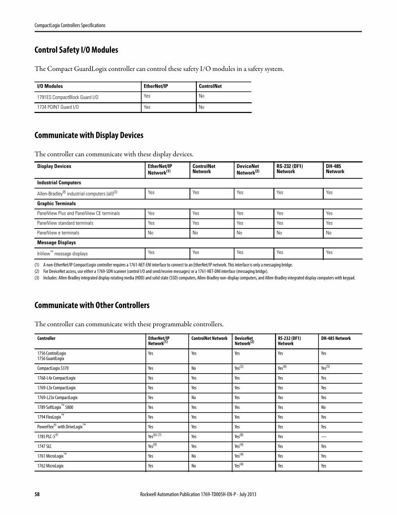
CompactLogix Controllers Specifications
Control Safety I/O Modules
The Compact GuardLogix controller can control these safety I/O modules in a safety system.
Communicate with Display Devices
The controller can communicate with these display devices.
Communicate with Other Controllers
The controller can communicate with these programmable controllers.
I/O Modules EtherNet/IP ControlNet
1791ES CompactBlock Guard I/O Yes No
1734 POINT Guard I/O Yes No
Display Devices EtherNet/IPNetwork(1)
(1) A non-EtherNet/IP CompactLogix controller requires a 1761-NET-ENI interface to connect to an EtherNet/IP network. This interface is only a messaging bridge.
ControlNetNetwork
DeviceNetNetwork(2)
(2) For DeviceNet access, use either a 1769-SDN scanner (control I/O and send/receive messages) or a 1761-NET-DNI interface (messaging bridge).
RS-232 (DF1)Network
DH-485Network
Industrial Computers
Allen-Bradley® industrial computers (all)(3)
(3) Includes: Allen-Bradley integrated display rotating media (HDD) and solid state (SSD) computers, Allen-Bradley non-display computers, and Allen-Bradley integrated display computers with keypad.
Yes Yes Yes Yes Yes
Graphic Terminals
PanelView Plus and PanelView CE terminals Yes Yes Yes Yes Yes
PanelView standard terminals Yes Yes Yes Yes Yes
PanelView e terminals No No No No No
Message Displays
InView message displays Yes Yes Yes Yes Yes
Controller EtherNet/IP Network(1)
ControlNet Network DeviceNet Network(2)
RS-232 (DF1) Network
DH-485 Network
1756 ControlLogix1756 GuardLogix
Yes Yes Yes Yes Yes
CompactLogix 5370 Yes No Yes(3) Yes(4) Yes(5)
1768-L4x CompactLogix Yes Yes Yes Yes Yes
1769-L3x CompactLogix Yes Yes Yes Yes Yes
1769-L23x CompactLogix Yes No Yes Yes Yes
1789 SoftLogix 5800 Yes Yes Yes Yes No
1794 FlexLogix Yes Yes Yes Yes Yes
PowerFlex with DriveLogix Yes Yes Yes Yes Yes
1785 PLC-5 Yes(6) (7) Yes Yes(8) Yes —
1747 SLC Yes(9) Yes Yes(4) Yes Yes
1761 MicroLogix Yes No Yes(4) Yes Yes
1762 MicroLogix Yes No Yes(4) Yes Yes
58 Rockwell Automation Publication 1769-TD005H-EN-P - July 2013
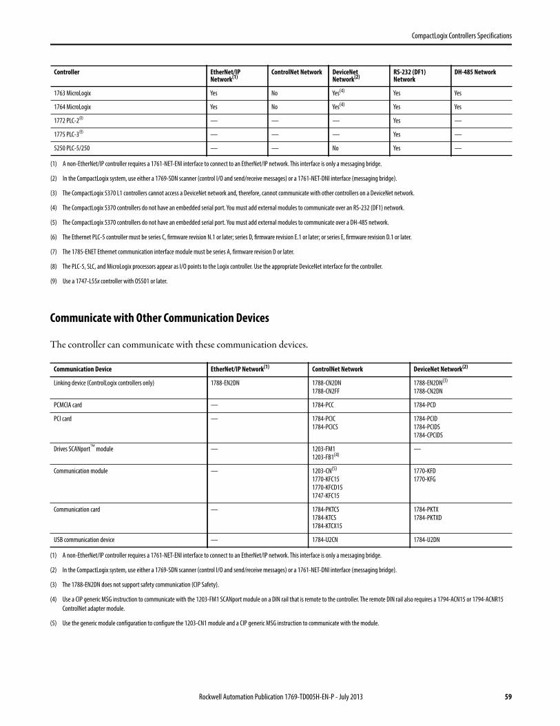
CompactLogix Controllers Specifications
Communicate with Other Communication Devices
The controller can communicate with these communication devices.
1763 MicroLogix Yes No Yes(4) Yes Yes
1764 MicroLogix Yes No Yes(4) Yes Yes
1772 PLC-2 — — — Yes —
1775 PLC-3 — — — Yes —
5250 PLC-5/250 — — No Yes —
(1) A non-EtherNet/IP controller requires a 1761-NET-ENI interface to connect to an EtherNet/IP network. This interface is only a messaging bridge.
(2) In the CompactLogix system, use either a 1769-SDN scanner (control I/O and send/receive messages) or a 1761-NET-DNI interface (messaging bridge).
(3) The CompactLogix 5370 L1 controllers cannot access a DeviceNet network and, therefore, cannot communicate with other controllers on a DeviceNet network.
(4) The CompactLogix 5370 controllers do not have an embedded serial port. You must add external modules to communicate over an RS-232 (DF1) network.
(5) The CompactLogix 5370 controllers do not have an embedded serial port. You must add external modules to communicate over a DH-485 network.
(6) The Ethernet PLC-5 controller must be series C, firmware revision N.1 or later; series D, firmware revision E.1 or later; or series E, firmware revision D.1 or later.
(7) The 1785-ENET Ethernet communication interface module must be series A, firmware revision D or later.
(8) The PLC-5, SLC, and MicroLogix processors appear as I/O points to the Logix controller. Use the appropriate DeviceNet interface for the controller.
(9) Use a 1747-L55x controller with OS501 or later.
Communication Device EtherNet/IP Network(1)
(1) A non-EtherNet/IP controller requires a 1761-NET-ENI interface to connect to an EtherNet/IP network. This interface is only a messaging bridge.
ControlNet Network DeviceNet Network(2)
(2) In the CompactLogix system, use either a 1769-SDN scanner (control I/O and send/receive messages) or a 1761-NET-DNI interface (messaging bridge).
Linking device (ControlLogix controllers only) 1788-EN2DN 1788-CN2DN
1788-CN2FF
1788-EN2DN(3)
1788-CN2DN
(3) The 1788-EN2DN does not support safety communication (CIP Safety).
PCMCIA card — 1784-PCC 1784-PCD
PCI card — 1784-PCIC
1784-PCICS
1784-PCID
1784-PCIDS
1784-CPCIDS
Drives SCANport module — 1203-FM1
1203-FB1(4)
(4) Use a CIP generic MSG instruction to communicate with the 1203-FM1 SCANport module on a DIN rail that is remote to the controller. The remote DIN rail also requires a 1794-ACN15 or 1794-ACNR15
ControlNet adapter module.
—
Communication module — 1203-CN(5)
1770-KFC15
1770-KFCD15
1747-KFC15
(5) Use the generic module configuration to configure the 1203-CN1 module and a CIP generic MSG instruction to communicate with the module.
1770-KFD
1770-KFG
Communication card — 1784-PKTCS
1784-KTCS
1784-KTCX15
1784-PKTX
1784-PKTXD
USB communication device — 1784-U2CN 1784-U2DN
Controller EtherNet/IP Network(1)
ControlNet Network DeviceNet Network(2)
RS-232 (DF1) Network
DH-485 Network
Rockwell Automation Publication 1769-TD005H-EN-P - July 2013 59
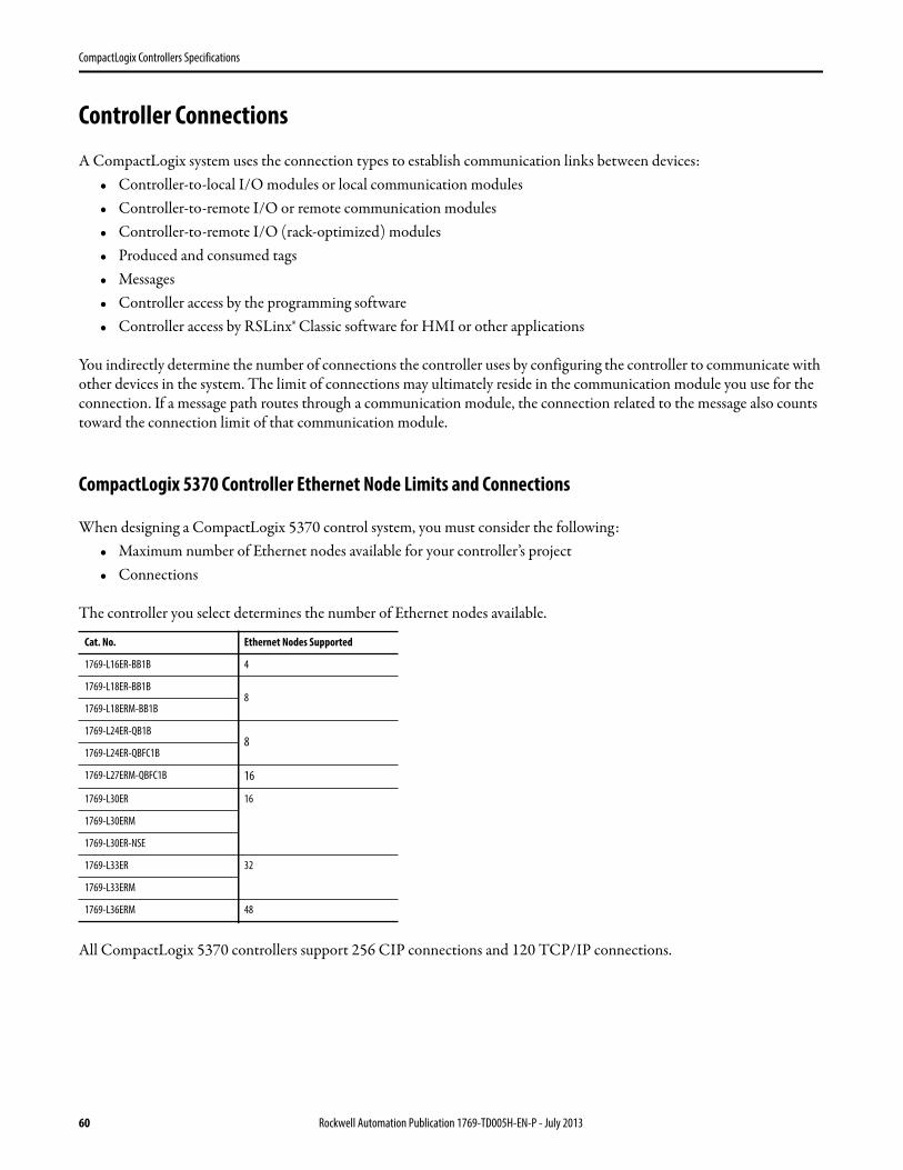
CompactLogix Controllers Specifications
Controller Connections
A CompactLogix system uses the connection types to establish communication links between devices:• Controller-to-local I/O modules or local communication modules• Controller-to-remote I/O or remote communication modules• Controller-to-remote I/O (rack-optimized) modules• Produced and consumed tags• Messages• Controller access by the programming software• Controller access by RSLinx® Classic software for HMI or other applications
You indirectly determine the number of connections the controller uses by configuring the controller to communicate with other devices in the system. The limit of connections may ultimately reside in the communication module you use for the connection. If a message path routes through a communication module, the connection related to the message also counts toward the connection limit of that communication module.
CompactLogix 5370 Controller Ethernet Node Limits and Connections
When designing a CompactLogix 5370 control system, you must consider the following:• Maximum number of Ethernet nodes available for your controller’s project• Connections
The controller you select determines the number of Ethernet nodes available.
All CompactLogix 5370 controllers support 256 CIP connections and 120 TCP/IP connections.
Cat. No. Ethernet Nodes Supported
1769-L16ER-BB1B 4
1769-L18ER-BB1B8
1769-L18ERM-BB1B
1769-L24ER-QB1B8
1769-L24ER-QBFC1B
1769-L27ERM-QBFC1B 16
1769-L30ER 16
1769-L30ERM
1769-L30ER-NSE
1769-L33ER 32
1769-L33ERM
1769-L36ERM 48
60 Rockwell Automation Publication 1769-TD005H-EN-P - July 2013
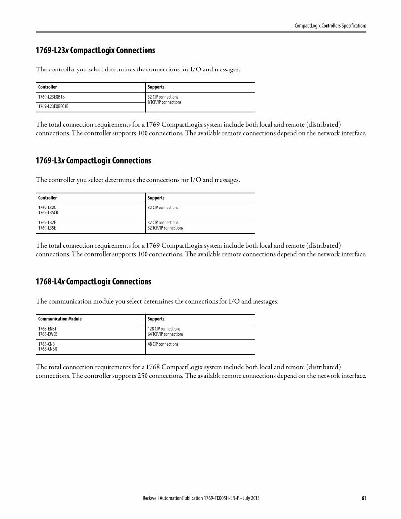
CompactLogix Controllers Specifications
1769-L23x CompactLogix Connections
The controller you select determines the connections for I/O and messages.
The total connection requirements for a 1769 CompactLogix system include both local and remote (distributed) connections. The controller supports 100 connections. The available remote connections depend on the network interface.
1769-L3x CompactLogix Connections
The controller you select determines the connections for I/O and messages.
The total connection requirements for a 1769 CompactLogix system include both local and remote (distributed) connections. The controller supports 100 connections. The available remote connections depend on the network interface.
1768-L4x CompactLogix Connections
The communication module you select determines the connections for I/O and messages.
The total connection requirements for a 1768 CompactLogix system include both local and remote (distributed) connections. The controller supports 250 connections. The available remote connections depend on the network interface.
Controller Supports
1769-L23EQB1B 32 CIP connections8 TCP/IP connections
1769-L23EQBFC1B
Controller Supports
1769-L32C1769-L35CR
32 CIP connections
1769-L32E1769-L35E
32 CIP connections32 TCP/IP connections
Communication Module Supports
1768-ENBT1768-EWEB
128 CIP connections64 TCP/IP connections
1768-CNB1768-CNBR
48 CIP connections
Rockwell Automation Publication 1769-TD005H-EN-P - July 2013 61
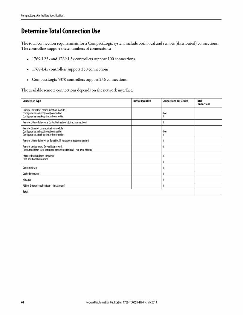
CompactLogix Controllers Specifications
Determine Total Connection Use
The total connection requirements for a CompactLogix system include both local and remote (distributed) connections. The controllers support these numbers of connections:
• 1769-L23x and 1769-L3x controllers support 100 connections.
• 1768-L4x controllers support 250 connections.
• CompactLogix 5370 controllers support 256 connections.
The available remote connections depends on the network interface.
Connection Type Device Quantity Connections per Device TotalConnections
Remote ControlNet communication moduleConfigured as a direct (none) connectionConfigured as a rack-optimized connection
0 or1
Remote I/O module over a ControlNet network (direct connection) 1
Remote Ethernet communication moduleConfigured as a direct (none) connectionConfigured as a rack-optimized connection
0 or1
Remote I/O module over an EtherNet/IP network (direct connection) 1
Remote device over a DeviceNet network(accounted for in rack-optimized connection for local 1756-DNB module)
0
Produced tag and first consumerEach additional consumer
2
1
Consumed tag 1
Cached message 1
Message 1
RSLinx Enterprise subscriber (16 maximum) 1
Total
62 Rockwell Automation Publication 1769-TD005H-EN-P - July 2013
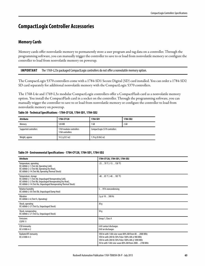
CompactLogix Controllers Specifications
CompactLogix Controller Accessories
Memory Cards
Memory cards offer nonvolatile memory to permanently store a user program and tag data on a controller. Through the programming software, you can manually trigger the controller to save to or load from nonvolatile memory or configure the controller to load from nonvolatile memory on powerup.
The CompactLogix 5370 controllers come with a 1784-SD1 Secure Digital (SD) card installed. You can order a 1784-SD2 SD card separately for additional nonvolatile memory with the CompactLogix 5370 controllers.
The 1768-L4x and 1769-L3x modular CompactLogix controllers offer a CompactFlash card as a nonvolatile memory option. You install the CompactFlash card in a socket on the controller. Through the programming software, you can manually trigger the controller to save to or load from nonvolatile memory or configure the controller to load from nonvolatile memory on powerup.
IMPORTANT The 1769-L23x packaged CompactLogix controllers do not offer a nonvolatile memory option.
Table 38 - Technical Specifications - 1784-CF128, 1784-SD1, 1784-SD2
Attribute 1784-CF128 1784-SD1 1784-SD2
Memory 128 MB 1 GB 2 GB
Supported controllers 1769 modular controllers
1768 controllers
CompactLogix 5370 controllers
Weight, approx 14.2 g (0.5 oz) 1.76 g (0.062 oz)
Table 39 - Environmental Specifications - 1784-CF128, 1784-SD1, 1784-SD2
Attribute 1784-CF128, 1784-SD1, 1784-SD2
Temperature, operatingIEC 60068-2-1 (Test Ad, Operating Cold),IEC 60068-2-2 (Test Bd, Operating Dry Heat),IEC 60068-2-14 (Test Nb, Operating Thermal Shock)
-25…70 °C (-13…158 °F)
Temperature, storageIEC 60068-2-1 (Test Ab, Unpackaged Nonoperating Cold),IEC 60068-2-2 (Test Bb, Unpackaged Nonoperating Dry Heat),IEC 60068-2-14 (Test Na, Unpackaged Nonoperating Thermal Shock)
-40…85 °C (-40…185 °F)
Relative humidityIEC 60068-2-30 (Test Db, Unpackaged Damp Heat)
5…95% noncondensing
VibrationIEC 60068-2-6 (Test Fc, Operating)
2 g @ 10…500 Hz
Shock, operatingIEC 60068-2-27 (Test Ea, Unpackaged Shock)
30 g
Shock, nonoperatingIEC 60068-2-27 (Test Ea, Unpackaged Shock)
50 g
Emissions
CISPR 11
Group 1, Class A
ESD immunity
IEC 61000-4-2
6 kV contact discharges
8 kV air discharges
Radiated RF immunity
IEC 61000-4-3
10V/m with 1 kHz sine-wave 80% AM from 80…2000 MHz
10V/m with 200 Hz 50% Pulse 100% AM @ 900 MHz
10V/m with 200 Hz 50% Pulse 100% AM @ 1890 MHz
3V/m with 1 kHz sine-wave 80% AM from 2000…2700 MHz
Rockwell Automation Publication 1769-TD005H-EN-P - July 2013 63
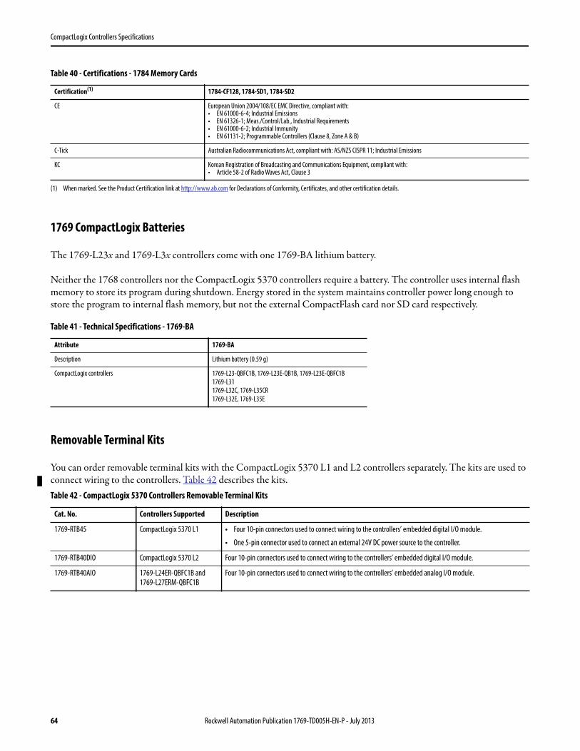
CompactLogix Controllers Specifications
1769 CompactLogix Batteries
The 1769-L23x and 1769-L3x controllers come with one 1769-BA lithium battery.
Neither the 1768 controllers nor the CompactLogix 5370 controllers require a battery. The controller uses internal flash memory to store its program during shutdown. Energy stored in the system maintains controller power long enough to store the program to internal flash memory, but not the external CompactFlash card nor SD card respectively.
Removable Terminal Kits
You can order removable terminal kits with the CompactLogix 5370 L1 and L2 controllers separately. The kits are used to connect wiring to the controllers. Table 42 describes the kits.
Table 40 - Certifications - 1784 Memory Cards
Certification(1)
(1) When marked. See the Product Certification link at http://www.ab.com for Declarations of Conformity, Certificates, and other certification details.
1784-CF128, 1784-SD1, 1784-SD2
CE European Union 2004/108/EC EMC Directive, compliant with:• EN 61000-6-4; Industrial Emissions• EN 61326-1; Meas./Control/Lab., Industrial Requirements• EN 61000-6-2; Industrial Immunity• EN 61131-2; Programmable Controllers (Clause 8, Zone A & B)
C-Tick Australian Radiocommunications Act, compliant with: AS/NZS CISPR 11; Industrial Emissions
KC Korean Registration of Broadcasting and Communications Equipment, compliant with:• Article 58-2 of Radio Waves Act, Clause 3
Table 41 - Technical Specifications - 1769-BA
Attribute 1769-BA
Description Lithium battery (0.59 g)
CompactLogix controllers 1769-L23-QBFC1B, 1769-L23E-QB1B, 1769-L23E-QBFC1B
1769-L31
1769-L32C, 1769-L35CR
1769-L32E, 1769-L35E
Table 42 - CompactLogix 5370 Controllers Removable Terminal Kits
Cat. No. Controllers Supported Description
1769-RTB45 CompactLogix 5370 L1 • Four 10-pin connectors used to connect wiring to the controllers’ embedded digital I/O module.
• One 5-pin connector used to connect an external 24V DC power source to the controller.
1769-RTB40DIO CompactLogix 5370 L2 Four 10-pin connectors used to connect wiring to the controllers’ embedded digital I/O module.
1769-RTB40AIO 1769-L24ER-QBFC1B and 1769-L27ERM-QBFC1B
Four 10-pin connectors used to connect wiring to the controllers’ embedded analog I/O module.
64 Rockwell Automation Publication 1769-TD005H-EN-P - July 2013
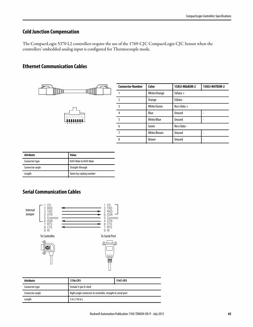
CompactLogix Controllers Specifications
Cold Junction Compensation
The CompactLogix 5370 L2 controllers require the use of the 1769-CJC CompactLogix CJC Sensor when the controllers’ embedded analog input is configured for Thermocouple mode.
Ethernet Communication Cables
Serial Communication Cables
Attribute Value
Connector type RJ45 Male to RJ45 Male
Connector angle Straight-through
Length Varies by catalog number
Attribute 1756-CP3 1747-CP3
Connector type Female 9-pin D-shell
Connector angle Right angle connector to controller, straight to serial port
Length 3 m (118 in.)
Connector Number Color 1585J-M8xBJM-2 1585J-M4TBJM-2
1 White/Orange TxData +
2 Orange TxData -
3 White/Green Recv Data +
4 Blue Unused -
5 White/Blue Unused -
6 Green Recv Data -
7 White/Brown Unused -
8 Brown Unused -
1 CD2 RXD3 TXD4 DTR5 Common6 DSR7 RTS8 CTS9 RI
1 CD3 TXD2 RXD6 DSR5 Common4 DTR8 CTS7 RTS9 RI
Internal Jumper
To Controller To Serial Port
Rockwell Automation Publication 1769-TD005H-EN-P - July 2013 65
CompactLogix Controllers Specifications
66 Rockwell Automation Publication 1769-TD005H-EN-P - July 2013

CompactLogix Controllers Specifications
Rockwell Automation Publication 1769-TD005H-EN-P - July 2013 67
Allen-Bradley, ArmorBlock, ArmorBlock MaXum, Compact I/O, CompactBlock, CompactLogix, ControlLogix, DriveLogix, FLEX, FLEX Ex, FlexLogix, Guard I/O, GuardLogix, InView, MicroLogix, PanelView, PLC-2, PLC-3, PLC-5, POINT I/O, POINTBlock, PowerFlex, Rockwell Software, Rockwell Automation, RSLinx, SCANport, SLC, SoftLogix, and LISTEN. THINK. SOLVE. are trademarks of Rockwell Automation, Inc.
Trademarks not belonging to Rockwell Automation are property of their respective companies.
Publication 1769-TD005H-EN-P - July 2013 Supersedes Publication 1769-TD005G-EN-P - December 2012 Copyright © 2013 Rockwell Automation, Inc. All rights reserved. Printed in the U.S.A.
Important User Information
Solid-state equipment has operational characteristics differing from those of electromechanical equipment. Safety Guidelines for the Application, Installation and Maintenance of Solid State Controls (publication SGI-1.1 available from your local Rockwell Automation sales office or online at http://www.rockwellautomation.com/literature/) describes some important differences between solid-state equipment and hard-wired electromechanical devices. Because of this difference, and also because of the wide variety of uses for solid-state equipment, all persons responsible for applying this equipment must satisfy themselves that each intended application of this equipment is acceptable.
In no event will Rockwell Automation, Inc. be responsible or liable for indirect or consequential damages resulting from the use or application of this equipment.
The examples and diagrams in this publication are included solely for illustrative purposes. Because of the many variables and requirements associated with any particular installation, Rockwell Automation, Inc. cannot assume responsibility or liability for actual use based on the examples and diagrams.
No patent liability is assumed by Rockwell Automation, Inc. with respect to use of information, circuits, equipment, or software described in this manual.
Reproduction of the contents of this manual, in whole or in part, without written permission of Rockwell Automation, Inc., is prohibited.
Documentation Feedback
Your comments will help us serve your documentation needs better. If you have any suggestions on how to improve this document, complete this form, publication RA-DU002, available at http://www.rockwellautomation.com/literature/.
Rockwell Otomasyon Ticaret A.Ş., Kar Plaza İş Merkezi E Blok Kat:6 34752 İçerenköy, İstanbul, Tel: +90 (216) 5698400