Operating instructions and spare parts list OptiStar CG07 ... · V 03/09 4 • General safety...
47
En Operating instructions and spare parts list OptiStar CG07-P Gun control unit Translation of the original operating instructions
Transcript of Operating instructions and spare parts list OptiStar CG07 ... · V 03/09 4 • General safety...

En
Operating instructions and spare parts list
OptiStar CG07-P Gun control unit
Translation of the original operating instructions

V 03/09
Documentation OptiStar CG07-P Gun control unit
© Copyright 2006 ITW Gema GmbH
All rights reserved.
This publication is protected by copyright. Unauthorized copying is pro-hibited by law. No part of this publication may be reproduced, photocop-ied, translated, stored on a retrieval system or transmitted in any form or by any means for any purpose, neither as a whole nor partially, without the express written consent of ITW Gema GmbH.
OptiFlex, OptiTronic, OptiGun, EasyTronic, EasySelect, OptiFlow and SuperCorona are registered trademarks of ITW Gema GmbH.
OptiStar, OptiSpray, OptiMatic, OptiMove, OptiMaster, OptiPlus, Multi-Tronic and Gematic are trademarks of ITW Gema GmbH.
All other product names are trademarks or registered trademarks of their respective holders.
Reference is made in this manual to different trademarks or registered trademarks. Such references do not mean that the manufacturers con-cerned approve of or are bound in any form by this manual. We have en-deavored to retain the preferred spelling of the trademarks, and regis-tered trademarks of the copyright holders.
To the best of our knowledge and belief, the information contained in this publication was correct and valid on the date of issue. ITW Gema GmbH makes no representations or warranties with respect to the contents or use of this publication, and reserves the right to revise this publication and make changes to its content without prior notice.
Printed in Switzerland
ITW Gema GmbH Mövenstrasse 17 9015 St. Gallen Switzerland
Phone: +41-71-313 83 00 Fax.: +41-71-313 83 83
E-Mail: [email protected] Homepage: www.itwgema.ch

V 03/09
OptiStar CG07-P Gun control unit Table of contents • 1
Table of contents
General safety regulations 3 Safety symbols (pictograms)...................................................................................3 Conformity of use....................................................................................................3 Product specific security measures ........................................................................4
About this manual 5 General information ................................................................................................5 Software version .....................................................................................................5
Function description 7 Field of application ..................................................................................................7 OptiStar CG07-P Gun control unit ..........................................................................7
Typical characteristics................................................................................7 Basic functions...........................................................................................8 Additional functions....................................................................................8 Functions - overview ..................................................................................8
Operating modes ....................................................................................................9 Predefined operating mode (Preset mode)................................................9 Adjustable operating mode (Program mode).............................................9
Technical data 11 OptiStar CG07-P Gun control unit ........................................................................11
General information .................................................................................11 Connectable guns ....................................................................................11 Electrical data ..........................................................................................12 Pneumatic data ........................................................................................12 Dimensions ..............................................................................................12 Air flow rates ............................................................................................12
Operating and display elements 13 Display and LEDs .................................................................................................13 Input keys and switches........................................................................................14
Start-up and operation 15 OptiStar CG07-P - connections ............................................................................15
Connecting guide .....................................................................................16 OptiStar CG07-P pin assignment.............................................................17
Initial start-up.........................................................................................................18 Setting the device type.............................................................................18 Preparing the powder hopper/container ..................................................18 Switch on the booth .................................................................................18
Daily start-up.........................................................................................................19 Select operating mode .............................................................................19 Setting powder output and powder cloud ................................................20 Level 2 display .........................................................................................20

V 03/09
2 • Table of contents OptiStar CG07-P Gun control unit
Setting the electrode rinsing air ............................................................... 21 Setting the fluidizing ................................................................................ 21 Powder coating........................................................................................ 22 Remote control by OptiSelect GM02 Manual gun................................... 22 Shut-down ............................................................................................... 22
Saving programs .................................................................................................. 22 Technical explanations concerning high voltage and spray current..................... 23
Characteristic curves of Preset mode ..................................................... 23 Characteristic curve of Program mode.................................................... 23
Technical explanations about automatic transport air/spraying air setting .......... 24 Transport air ............................................................................................ 24 Setting the spraying air............................................................................ 24
Additional functions 25 System parameter P0........................................................................................... 25
Entering the system parameters ............................................................. 25 Exiting the system parameter mode........................................................ 25
Trigger counter and software request .................................................................. 26 Keyboard lock....................................................................................................... 26 Powder output/powder hose correction................................................................ 26
Carrying out a powder output correction ................................................. 26 Procedure (powder output correction)..................................................... 27 Procedure (powder hose correction) ....................................................... 27
RAM reset............................................................................................................. 28 Cleaning mode ..................................................................................................... 29
Cleaning programs .................................................................................. 29
Schematic diagrams 31 OptiStar CG07-P - pneumatic diagram ................................................................ 31 OptiStar CG07-P - wiring diagram........................................................................ 32
Troubleshooting 33 Repairing the electrical part of the control unit ..................................................... 33
Replacing the fuse(s)............................................................................... 33 Replacing the power supply board .......................................................... 33 Replace the front plate ............................................................................ 34
Repairing the pneumatic part ............................................................................... 35 Replacing the pneumatic part.................................................................. 35 Removing the pneumatic hoses .............................................................. 35 Fitting the pneumatic hoses..................................................................... 35
Error diagnosis of the software............................................................................. 35 General information ................................................................................. 35 Error codes .............................................................................................. 36 Help codes list ......................................................................................... 37 Appearance of errors............................................................................... 37
Spare parts list 39 Ordering spare parts............................................................................................. 39 OptiStar CG07-P Gun control unit - general......................................................... 40 OptiStar CG07-P - inside rear wall ....................................................................... 41 OptiStar CG07-P - outside rear wall ..................................................................... 42 OptiStar CG07-P - enclosure and power pack ..................................................... 43 OptiStar CG07-P - front plate ............................................................................... 44 Diffuser ................................................................................................................. 45

V 03/09
OptiStar CG07-P Gun control unit General safety regulations • 3
General safety regulations
This chapter sets out the fundamental safety regulations that must be fol-lowed by the user and third parties using the OptiStar CG07-P Gun contr-ol unit.
These safety regulations must be read and understood before the OptiStar CG07-P Gun control unit is used.
Safety symbols (pictograms) The following warnings with their meanings can be found in the ITW Gema operating instructions. The general safety precautions must also be followed as well as the regulations in the operating instructions.
DANGER! Danger due to live electricity or moving parts. Possible consequences: Death or serious injury
WARNING! Improper use of the equipment could damage the machine or cause it to malfunction. Possible consequences: minor injuries or damage to equip-ment
INFORMATION! Useful tips and other information
Conformity of use 1. The OptiStar CG07-P Gun control unit is built to the latest speci-
fication and conforms to the recognized technical safety regula-tions. It is designed for the normal application of powder coating.
2. Any other use is considered as non-conform. The manufacturer is not responsible for damage resulting from improper use of this equipment; the end-user alone is responsible. If the OptiStar CG07-P Gun control unit is to be used for other purposes or other substances outside of our guidelines, then ITW Gema GmbH should be consulted.
3. Observance of the operating, service and maintenance instruc-tions specified by the manufacturer is also part of conformity of

V 03/09
4 • General safety regulations OptiStar CG07-P Gun control unit
use. The OptiStar CG07-P Gun control unit should only be used, maintained and started up by trained personnel, who are in-formed about and are familiar with the possible hazards involved.
4. Start-up (i.e. the execution of a particular operation) is forbidden until it has been established that the OptiStar CG07-P Gun contr-ol unit has been set up and wired according to the guidelines for machinery (98/37 EG). EN 60204-1 (machine safety) must also be observed.
5. Unauthorized modifications to OptiStar CG07-P Gun control unit exempts the manufacturer from any liability from resulting dam-age.
6. The relevant accident prevention regulations, as well as other generally recognized safety regulations, occupational health and structural regulations are to be observed.
7. Furthermore the country-specific safety regulations must be ob-served.
Explosion protection Protection type Temperature class
II (2) 3 D IP54 T6 (zone 21) T4 (zone 22)
Product specific security measures - The installation work, to be done by the customer, must be
carried out according to local regulations
- Before starting up the plant a check must be made that no foreign objects are in the booth or in the ducting (input and exhaust air)
- It must be observed, that all components are grounded ac-cording to the local regulations, before start-up
Note: For further security information, see the more detailed ITW Gema safety regulations!

V 03/09
OptiStar CG07-P Gun control unit About this manual • 5
About this manual
General information This operating manual contains all the important information which you require for the working with the OptiStar CG07-P Gun control unit. It will safely guide you through the start-up process and give you references and tips for the optimal use of your new powder coating system.
Information about the function mode of the individual system components - booth, powder gun control unit, manual gun or dense phase pump - should be referenced to their corresponding documents.
Software version This document describes the operation of the OptiStar CG07-P Gun con-trol unit, with software version starting from 1.10!


V 03/09
OptiStar CG07-P Gun control unit Function description • 7
Function description
Field of application The OptiStar CG07-P Gun control unit is designed exclusively for control-ling the OptiSpray DPP01 Dense phase pump (see also in chapter "Technical data").
Any other use is considered as non-conform. The manufacturer is not re-sponsible for any damage resulting from this - the risk for this is assumed by the user alone!
For a better understanding of the interrelationships in powder coating, it is recommended to read completely the operating instructions of the other components, so as to be familiar with their functions too!
OptiStar CG07-P Gun control unit
Typical characteristics - The OptiStar CG07-P Gun control unit is used for the elec-
trostatic powder coating with an OptiFlex manual equipment in addition to an OptiSpray DPP01Dense phase pump
- The OptiStar CG07-P Gun control unit allows the configura-tion of process parameters (air and high voltage settings), system parameters, process data, status information and correction values. All air volumes can be controlled centrally by the unit
- The handling is simple and self-explanatory. The coating personnel can save individual settings, based off personnel experience, in 20 program places
- All settings for efficient powder coating are simple to operate and repeatable. The control unit electronics permit the exact amount of powder delivery and the adjusted values can be read on the digital displays
- The OptiStar CG07-P Gun control unit can be connected to mains voltages between 100-240 VAC, 50-60 Hz (single phase alternating current)

V 03/09
8 • Function description OptiStar CG07-P Gun control unit
Basic functions - Intuitive operation
- Setting and display of the values on two levels
- Saving/recalling of process parameters in the form of pro-grams
- Remote control feature on the manual powder gun (OptiSe-lect GM02 only)
Additional functions - Spray current regulation with high voltage limitation
- Control of the air volumes for the operation of the OptiSpray DPP01 Dense phase pump and the electrode rinsing air
- Status indications and error diagnosis
Functions - overview
Setting possibilities - Setting possibilities for powder output volume, total air, spray
current, high voltage and electrode rinsing air
- Correction values for powder offset, powder hose correction value, daily correction and transport air offset
Request values - Request values for software version and trigger hours
counter
Features - Keyboard lock, predefined mode (Preset Mode), 20 pro-
grams, error display and remote control on the manual pow-der gun (OptiSelect GM02)

V 03/09
OptiStar CG07-P Gun control unit Function description • 9
Operating modes The OptiStar CG07-P Gun control unit can be operated with two operat-ing modes. According to the selected application mode, spray voltage and spray current are automatically adjusted and limited.
Predefined operating mode (Preset mode) The OptiStar CG07-P Gun control unit provides three predefined applica-tion modes (flat parts, complicated parts and recoat parts already painted).
In this operating mode, current (µA) and high voltage (kV) are preset, powder and air volume can be set and saved for each application mode separately.
The remaining preset values are not changed by transition to the prede-fined operating mode and can be configured and saved furthermore.
Adjustable operating mode (Program mode) In this operating mode, 20 individually definable programs (P01-P20) are available. These programs are automatically saved and can be recalled again as the application requires.
The values for current, high voltage, powder output, total air and elec-trode rinsing air can be set as needed.
Note: The specified settings in the 20 programs and 3 application modes are saved automatically, without confirmation, after a two second delay and the display changes from preset values to actual values!


V 03/09
OptiStar CG07-P Gun control unit Technical data • 11
Technical data
OptiStar CG07-P Gun control unit
General information The CG07-P Gun control unit controls the OptiSpray DPP01 Dense phase pump, which supplies the powder to the gun.
Connectable guns OptiStar CG07-P connectable
OptiSelect GM02 yes, with diffuser
OptiGun GA02 yes,
with diffuser and trigger adaptor
PG1 no PG2-A no TriboJet no
Attention: The OptiStar CG07-P Gun control unit can only be used with the specified gun types!

V 03/09
12 • Technical data OptiStar CG07-P Gun control unit
Electrical data OptiStar CG07-P Nominal input voltage 100-240 VAC Frequency 50-60 Hz Input power 40 VA Nominal output voltage (to the gun) max. 12 V Nominal output current (to the gun) max. 1 A Protection type IP54
Temperature range 0 °C - +40 °C (+32 °F - +104 °F)
Max. operating temperature 85 °C (+185 °F)
Approvals II (2) 3 D PTB05 ATEX 5009
FM Approvals
Pneumatic data OptiStar CG07-P Compressed air connection Elbow connection, 8 mm Input pressure (dynamic) 6.0 bar / 87 psi Max. water vapor content of compressed air 1.3 g/m³ Max. oil vapor content of compressed air 0.1 mg/m³
Dimensions OptiStar CG07-P Width 248 mm Depth 250 mm Height 174 mm Weight approx. 5.2 kg
Air flow rates The input pressure of the OptiStar CG07-P Gun control unit has to be set dynamically (setting during powder coating) to 6.0 bar!
OptiStar CG07-P Electrode rinsing air flow rate 0-3 Nm³/h Transport air flow rate 0-5 Nm³/h Spraying air flow rate 0-5 Nm³/h Fluidizing air flow rate (OptiFlex FP) 0-5 Nm³/h

V 03/09
OptiStar CG07-P Gun control unit Operating and display elements • 13
Operating and display elements
Display and LEDs
OptiStar CG07-P Gun control unit - display and LEDs
Designation Function
A1-A4 Display of actual values, preset values and system pa-rameters
A5 Display of program numbers, error diagnosis codes and status information
A1 (level 2) Transport air (display in Nm³/h) A2 (level 2) Spraying air (display in Nm³/h) L1 Powder output (display in %) L2 Total air volume (display in Nm³/h) L3 Spraying current (display in µA) L5 High voltage (display in kV) L6 Electrode rinsing air (display in Nm³/h)
A3 A4
L1 L2
L13
L14
L15
L3 L5 L6 A1 A2
A5
L7

V 03/09
14 • Operating and display elements OptiStar CG07-P Gun control unit
Designation Function L7 Activation of fluidization L13 Application mode for flat parts is activated L14 Application mode for complicated parts is activated
L15 Application mode for recoating parts already coated is acti-vated
Input keys and switches
OptiStar CG07-P Gun control unit - input keys and switches
Designation Function T1-T8 Input keys for preset values and system parameters T9 (Select) Switch between display levels T10-T11 Program change T12 (P) Program selection for user-defined programs (max. 20) T13 Application mode for flat parts (fix values)
T14 Application mode for complicated parts with depressions (fixed values)
T15 Application mode for overcoating parts already coated (fixed values)
T16 Switching on and off the fluidization Switch to system parameter mode (press for at least 5 secs)
S1/S2 Power switch ON/OFF
T1 T2 T3 T4
T5 T6 T7 T8
T9
T10 T11T12
T14
T13 T15
T16 S1 S2

V 03/09
OptiStar CG07-P Gun control unit Start-up and operation • 15
Start-up and operation
OptiStar CG07-P - connections
OptiStar CG07-P Gun control unit - connections on the rear side
Connection Description 1.1 Main air IN Compressed air connection 2.1 Power IN Mains cable connection (100-240 VAC) 2.2 Gun Gun cable connection 2.5 Ext. DPP01 Dense phase pump connection
1.5 Fluidizing air connection
1.4 Electrode rinsing air connection
1.3 Spraying air connection
1.2 Transport air connection
Grounding connection

V 03/09
16 • Start-up and operation OptiStar CG07-P Gun control unit
Connecting guide 1. Connect the compressed air supply from the compressed air cir-
cuit to the Main air IN connection (elbow connection, 8 mm) on the rear side of the control unit
Note: The compressed air must be free from oil and water!
2. Connect the grounding cable to the control unit with the grounding screw, and the 5 m long grounding cable with the clamping clip to the booth or the conveyor. Check ground connections with Ohm meter and ensure 1 MOhm or less
3. Connect the black hose for fluidizing air (electrically conduc-tive) to the output 1.5 on the rear side of the control unit
4. Connect the gun cable plug to the socket 2.2 on the rear side of the control unit
5. Connect the rinsing air hose to the electrode rinsing air output 1.4 and to the powder gun
6. Connect the gun to the outgoing powder hose of the OptiS-pray DPP01 Dense phase pump
7. Connect the spraying air hose to the output 1.3 on the rear side of the control unit and to the diffuser on the powder gun
8. Connect the transport air hose to the output 1.2 on the rear side of the control unit and to the OptiSpray DPP01 Dense phase pump
9. Connect the mains cable to the 2.1 Power IN plug and fasten it

V 03/09
OptiStar CG07-P Gun control unit Start-up and operation • 17
Connection with manual gun
OptiStar CG07-P pin assignment
Power IN connection 1 Neutral conductor (power supply) 2 Phase (100-240 VAC) 3 empty
PE Ground PE
Gun connection 1 Ground 2 Remote control 1 (GM02) 3 Ground 4 Trigger 5 Remote control 2 (GM02) 6 Oscillator
PE Ground PE
2
PE 3
1
3
1 2 4
5 PE
6
Filter regulating valve
Manual gun
Fluidizing air

V 03/09
18 • Start-up and operation OptiStar CG07-P Gun control unit
Dense phase pump connection A-J Control signal valve 1-9 K IDENT / Recognition L REQUEST / Request M GND / Ground
Enclosure Shield
Initial start-up
Setting the device type Adjust the corresponding device type (fluidizing) by pressing the T16 key (see chapter "System parameter P0" for more details).
Note: If the control unit is supplied as a component of a complete Opti-Flex unit, the corresponding system parameter is set correctly by the factory! System parameter P0=0
Fluidizing air behavior Device type Fluidizing air function Fluidizing device (OptiFlex F)
Fluidizing air is controlled by two different methods: Turning on the fluidization key T16 will feed air to the hopper until key is turned off Triggering the gun is turning on the fluidization too, fluidization can be turned off with key T16
Note: After changing the device type from P0=3 to P0=0 (fluidizing de-vice), a RAM reset must be done!
Preparing the powder hopper/container Prepare the powder hopper (reference the corresponding operating manual).
Switch on the booth Switch on the powder coating booth according to its operating manual.

V 03/09
OptiStar CG07-P Gun control unit Start-up and operation • 19
Daily start-up The daily start-up of the OptiStar CG07-P Gun control unit takes place by the following steps:
Select operating mode Select the predefined application mode (Preset mode) or the adjust-able application mode (Program mode).
1. Turn on the gun control unit with the ON key
2. Select the corresponding application mode with the key T12 (for Program mode) or the application keys T13/T14/T15 (for Preset mode)
Starting the predefined operating mode (Preset mode) Select the Preset mode with the keys T13/T14/T15. The LED of the cor-responding application key illuminates. No program number will be shown on the display A5. The values for powder output and total air vol-ume, indicated before the changeover, are maintained.
Application mode for flat parts This application mode is suitable for the coating of simple, flat work-pieces without larger cavities.
Application mode for complicated parts This application mode is suitable for the coating of three-dimensional workpieces with complicated shapes (e.g. profiles).
Application mode for recoating parts already coated This application mode is suitable for the overcoating of workpieces which are already coated.
The three application modes have predefined values for high voltage and spray current:
Presetting Desired µA Desired kV Flat parts 100 100 Complicated parts 22 100 Overcoating 10 100

V 03/09
20 • Start-up and operation OptiStar CG07-P Gun control unit
Exiting the Preset mode Exit the Preset mode with the keys T10, T11 or T12. The preset values of the Program mode used before the Preset mode are displayed by the control unit memory.
Starting the adjustable operating mode (Program mode) Select this application mode with the program key T12. Here, 20 indi-vidually adjustable programs can be defined and saved. The programs 1-20 are loaded with preset values by factory. Factory preset values are 60% powder output at 4.0 Nm³/h total air and 20 µA spray current at 80 kV high voltage.
Setting powder output and powder cloud The powder output depends on the selected powder output and the ad-justed total air volume.
Setting the total air volume Adjust the total air volume with the keys T3/T4 (see therefore the OptiS-pray DPP01 Dense phase pump operating manual). The factory default value is set on 4.0 Nm³/h.
Setting the powder output Adjust the powder output volume according to the desired coating thick-ness. The selection takes place with the keys T1/T2 on the control unit or with the +/- keys on the rear side of the powder gun (OptiSelect gun type). The factory default setting is 60%.
Check the powder fluidization (see therefore chapter "Setting the fluidiz-ing").
Note: The transport air and the spraying air setting takes place auto-matically by the device, based on the adjusted powder output volume, the total air volume and the correction factor settings!
Level 2 display
Level 2 display
The level 2 display is show by pressing the Select key. In the lower two display areas, the values for fluidizing air and electrode rinsing air

V 03/09
OptiStar CG07-P Gun control unit Start-up and operation • 21
can be adjusted. In the upper two display areas, the calculated values for transport air and spraying air are displayed.
For details, see chapter "Technical explanations about automatic trans-port air/spraying air setting". If no key is pressed for 6 seconds, the dis-play switches back to level 1.
Setting the electrode rinsing air Adjust the correct electrode rinsing air according to the applied nozzles (deflector plate, flat jet nozzle)
1. Press the key T9 (SELECT) The second display level will be shown
2. Press the keys T7/T8 Here, the corresponding air volume value is entered
3. If this display level is not operated for 6 seconds, the first display level will be switched over independently
Setting the fluidizing The powder fluidizing depends on the powder type, the air humidity and the ambient temperature.
Procedure:
1. Adjust the air mover by turning the ball valve fully open and adjusting the throttle valve as required
2. Open the powder hopper cover
3. Switch on the fluidizing air with the key T16
4. Press key T9 (SELECT) The second display level will be switched over
5. Adjust the fluidizing air with the keys T5/T6
- If the adjustment keys (+ or -) are not operated for 6 seconds, the display will switch to the first display level
- The powder should "boil" lightly and regularly, if nec-essary, mix the powder with a stick
6. Close the cover
7. The fluidization can be switched off with the key T16, if re-quired. By pressing the gun trigger, the fluidization switches on automatically

V 03/09
22 • Start-up and operation OptiStar CG07-P Gun control unit
Powder coating
Attention: Make sure first, that all electrically conductive parts within 5 m of the coating booth are grounded!
1. Point the gun into the coating booth, but do not direct it to the object to be coated
2. Select the operating mode: Select the operating mode with program key T12 or the application keys T13/T14/T15. The LED of the corre-sponding application key illuminates
3. Press the powder gun trigger
4. Coat the objects
Remote control by OptiSelect GM02 Manual gun Various functions can be remotely controlled with the + and - keys on the rear side of the powder gun (OptiSelect GM02 type):
- Modify the powder output (press the + or - key on the gun). The powder output will be increased or decreased accord-ingly
- Change the application modes (Preset mode/Program mode) by pressing the + and - keys on the gun at the same time. The change takes place counterclockwise. Check by observ-ing the key LEDs on the control unit
Note: By pressing one of the keys, the preset values will be shown for 3 seconds!
Shut-down The shut-down of the OptiStar CG07-P Gun control unit takes place in following steps:
1. Loose the gun trigger
2. Switch off the control unit with the key S2
3. Switch off the Airmover
Saving programs
Note: The values in the programs 1-20 and the 3 preset application modes are saved automatically, without confirmation!

V 03/09
OptiStar CG07-P Gun control unit Start-up and operation • 23
Technical explanations concerning high voltage and spray current
Characteristic curves of Preset mode The preset values for high voltage and spray current in the predefined operation mode (Preset mode) are to be taken as reference points. The modification of these values has effects on the characteristic curve of the gun (see diagram). The operator can optimize the application within the possible three ranges.
Characteristic curve of Program mode In the user-defined operating mode (Program mode), the values for high voltage and spray current are adjustable. The operator can optimize the values for his application by utilizing the ranges below (see diagram).
Spray current (µA)
Hig
h vo
ltage
(kV)
Characteristic curve of Program mode
Spray current (µA)
Hig
h vo
ltage
(kV)
Characteristic curves of Preset mode
Preset values: Flat parts: 100kV/100uA Complicated parts: 100kV/22uA Overcoating: 100kV/10uA

V 03/09
24 • Start-up and operation OptiStar CG07-P Gun control unit
Technical explanations about automatic transport air/spraying air setting
Transport air The transport air will be used for conveying the powder from the dense phase pump to the powder gun. The transport air quantity will be set automatically by the device, based on the adjusted powder quantity and an adjustable correction factor (transport air offset C3).
The transport air calculation depends furthermore on the correction factors C1 and C2, which are also considered.
Characteristic curve of the transport air
Setting the spraying air The spraying air (ZL) will be defined in accordance to the calculated transport air (TL) and the adjusted total air volume (GL).
Formula:
GL = ZL + TL
Air streams in the diffuser
Tran
spor
t air
[Nm
3 /h]
GL
TL
ZL
Transport air (TL) calculation
Powder quantity [%]

V 03/09
OptiStar CG07-P Gun control unit Additional functions • 25
Additional functions
System parameter P0 The OptiStar CG07-P Gun control unit is configured with the system pa-rameter P0. The configuration will be saved in the control unit memory.
The system parameters are shown on the display A5 with additional al-phanumeric abbreviated designations (for function and condition).
Entering the system parameters 1. To enter the system parameter mode, press the key T16
longer than 5 seconds
2. The system parameter number is shown in the display A1 with a P placed in front
3. Adjust the corresponding system parameter value (device type) with the keys T5/T6. The value of the adjusted system parameter appears on dis-play A3
4. The system parameter P0 must be set to F (fluidizing device)
Name Description Values Display
P0 Device type
0 - Fluidizing device (type F) 1 - Box device (vibrator) (type B) 2 - Agitator device (type S) 3 - Automatic device 4 - Manual device with fluidization
F B S A S Fd
Default values are marked by bold print
Note: After modifying the system parameter P0, a RAM reset must be done, so that the default values are corrected!
Exiting the system parameter mode Exit the system parameter mode with the key T16, and the actual values display will appear. The modified values will be saved in the equipment memory.

V 03/09
26 • Additional functions OptiStar CG07-P Gun control unit
Trigger counter and software request The status information can be indicated on display A5 by pressing a combination of two different keys as shown. First press and hold key T12, then press either key T10 or T11 depending on requested information.
Status information Key combination Trigger ten-hours counter (total time in ten hours of gun trigger time). Trigger counter can not be reset! T12 with T10
Software version T12 with T11
The status display is shown as long as a key is held.
Keyboard lock The OptiStar CG07-P Gun control unit contains a keyboard lock, which prevents changing individual values for each parameter (kV, µA etc.) within an application mode (Preset or Program). The following is not af-fected by the keyboard lock and will still operate under normal conditions:
- Program selection
- Display of preset values of the current program
- Displaying the actual values
- Error acknowledgement
- The keyboard lock is activated and deactivated by pressing and holding key T9 (SELECT) and then key T11, the LED L11 (REMOTE) flashes. The keyboard lock status remains stored, when switching the equipment off and on. If a mem-ory reset takes place, the keyboard lock will be deactivated
Powder output/powder hose correction The OptiStar CG07-P Gun control unit can be adapted with the correction values optimally to local conditions (e.g. the adaption of different powder outputs in the plant).
Carrying out a powder output correction Powder output corrections are made at the first start-up, after a service work, after the solution of application problems, or by using different hose diameters!
It is recommended to create a table with input fields for each gun (see chapter "Example table for powder output/powder hose correction"), so that, if a possible system reset takes place, an access to these data can take place.

V 03/09
OptiStar CG07-P Gun control unit Additional functions • 27
The guide values can be extract from the following table:
Corr.-value Description Range Default value
C0 Powder offset (ms) 0-50 20
C1 Powder hose correction value (%) 40-100 100
C2 Daily correction value (%) 50-150 100
C3 Transport air offset (Nm³/h) 0-2.0 0.5
Procedure (powder output correction) 1. Set the total air to 4.0 (Nm³/h) on the A2 display. Set the
powder output to 00 (%) on the A1 display
2. To enter the system parameter mode, press the key T16 longer than 5 seconds. The correction factor number is shown in the display A2 with a C placed in front
3. Set the correction value for minimum powder output C0 to 20 (ms) on the A4 display with the keys T7/T8
4. Set the correction value for maximum powder output C1 to 100 (%) on the A4 display
For the next steps a measuring bag is necessary, for weighing the pow-der output. If possible, one bag should be used for each gun. Do not for-get to note the dead weight of each individual measuring bag.
5. Put the measuring bag over the gun nozzle and fasten it. Switch on the gun for 60 seconds
6. After this time has elapsed, switch off the gun, remove the measuring bag and weigh it. The powder output should be between 10-15 gr.
7. If no powder is expelled from the gun, return to the system parameter mode and increase the minimum powder output value C0 (range 0-50 ms)
8. Repeat steps 5 and 6, until the powder output amounts to 10-15 g. Annotate the adjusted minimum powder output value C0 in the table
Exit the system parameter mode by pressing the key T16.
Procedure (powder hose correction) The powder hose correction is only needed if several guns must have the same powder output amount.
1. Set the powder output value to 80 (%) on the A1 display
2. Put the measuring bag over the gun nozzle and fasten it. Switch on the gun for 60 seconds
3. Switch off the gun after 60 seconds, remove the measuring bag and weigh it
4. Annotate the powder output in g/min in the table

V 03/09
28 • Additional functions OptiStar CG07-P Gun control unit
Calculate the powder output correction according to following formula:
smallest powder output
C1 (%) = measured powder output
x 100
5. Annotate the calculated values (C1) for each individual gun in the table and enter the values to the control unit (therefore, repeat the steps 2 and 3)
Note: The daily correction value (C2) can be used to allow high powder volumes!
Note: The hose length correction factor (C1) is chosen in such a way, that no powder is visible if the powder output quantity is 0%, by increas-ing the value, the powder becomes visible. This performance de-pends on the hose length and the hose diameter!
Note: The transport air offset (C3) can be used to correct the powder out-put if it is spitting or inconsistent!
RAM reset The RAM reset enables a restore of factory settings of the OptiStar CG07-P Gun control unit. All user-defined values in Program and Preset mode will be set to factory default. The adjusted device type in system parameter P0 remains stored thereby, and an active keyboard lock will be deactivated.
Execute the RAM reset by pressing the key T16 and the ON switch for 5 seconds.
Note: By resetting the RAM, all user-made settings will be set to factory default!
Note: After modifying the system parameter P0, a RAM reset must be done!

V 03/09
OptiStar CG07-P Gun control unit Additional functions • 29
Cleaning mode The cleaning mode enables the cleaning of the dense phase pump and the powder hose. Three different rinsing programs are available to pre-pare the dense phase pump for a color change.
Activate the cleaning mode by pressing the program key T12 for 5 secs. The activated cleaning mode is indicated by a circulating luminous seg-ment in the display A5. The individual cleaning programs are selected with the keys T13, T14 and T15, thereby, the LED of the corresponding program blinks. The cleaning program will be started by activating the gun trigger (OptiStar CG07-P) or by activation of the powder gun (OptiS-tar CG06-CP).
Cleaning programs
Powder chamber emptying In this cleaning program (key T13), some air is blown through the filter elements in the powder chambers. The cleaning process can be addi-tionally supported by blowing compressed air into the suction hose.
Note: The dense phase pump may be cleaned with a pressure of max. 4 bar!
Cleaning the hose to the gun In this cleaning program (key T14), the powder hose to the gun will be cleaned with 8 long and 18 short air blasts for each powder chamber. During this time, the pinch valves on the suction side remain closed.
Cleaning the hose on the suction side In this cleaning program (key T15), the powder hose on the inlet of the dense phase pump will be cleaned with 8 long and 18 short air blasts for each powder chamber. During this time, the pinch valves on the output to the gun remain closed.
Attention: Large dust formation possible! The powder hose and the powder gun must be pointed into the booth during the cleaning procedure!
The cleaning mode is terminated by pressing the program key T12.


V 03/09
OptiStar CG07-P Gun control unit Schematic diagrams • 31
Schematic diagrams
OptiStar CG07-P - pneumatic diagram
OptiStar CG07-P - pneumatic diagram
CG07-P Gun control unit
Air supply
6.0 bar, dynamically, from the pressure regulator
Transport air Spraying air Electrode rinsing air
Fluidizing air

V 03/09
32 • Schematic diagrams OptiStar CG07-P Gun control unit
OptiStar CG07-P - wiring diagram
OptiStar CG07-P - wiring diagram, part 1
OptiStar CG07-P - wiring diagram, part 2
KEYBOARD

V 03/09
OptiStar CG07-P Gun control unit Troubleshooting • 33
Troubleshooting
Repairing the electrical part of the control unit
Attention, danger! Before starting the work on the control unit, disconnect the mains plug!
Replacing the fuse(s) 1. Loosen the screws on the front side of the enclosure
2. Hold the front plate with one hand, remove the fuse(s) from the fuse holder and replace with a new one
Fuse(s)
3. Reattach the front plate
4. Reconnect the mains cable
Replacing the power supply board 1. Loosen the screws on the front side of the enclosure
2. Disconnect the plugs on the defective board
3. Squeeze the standoffs with a pointed pliers and remove the power supply board. Replace the defective standoffs
4. Place the new board on the standoffs, press them into the board and snap into mounting bracket within enclosure. Reconnect the plugs
5. Reassemble the control unit in reverse order as described and install it

V 03/09
34 • Troubleshooting OptiStar CG07-P Gun control unit
6. Reconnect the mains cable
Replace the front plate 1. Loosen the screws on the front side of the enclosure
2. Disconnect all plugs from the front plate
3. Replace the front plate
4. Reassemble the front plate and the control unit in reverse order as described and install it
Attention: The motor plugs are to be put in according to the annotation!
5. Reconnect the mains cable
Note: If there are any problems or uncertainties, please contact a ITW Gema service center!
OptiStar CG07-P - configuration
Conveying air
Spraying air
Rinsing air
Fluidizing air
Power input
Gun
Empty Power pack input (AC)
Power pack output (DC)
DPP Module
not occupied
Valve
not occupied
not occupied

V 03/09
OptiStar CG07-P Gun control unit Troubleshooting • 35
Repairing the pneumatic part
Replacing the pneumatic part 1. Remove every electric and pneumatic connection on the
rear side of the control unit (disconnect mains cable and remove compressed air supply)
2. Loosen the screws on the rear side of the enclosure
3. Remove the pneumatic hoses from the part to be replaced (see chapter "Removing the pneumatic hoses")
4. Dismantle the defective part and replace it
5. Reconnect the pneumatic hoses (see chapter "Fitting the pneumatic hoses")
6. Reassemble the control unit in reverse order as described and install it
Removing the pneumatic hoses Before replacing a pneumatic part, all corresponding pneumatic hoses should always be disconnected first. This happens by pressing the ring on the quick release coupling of the hose. The hose can be pulled out easily.
Fitting the pneumatic hoses In order to reconnect the pneumatic hoses, proceed as follows:
- Insert the hose in the quick release coupling up to the end stop. The hose is held firmly again
Note: If there are any problems or uncertainties, please contact a ITW Gema service center!
Error diagnosis of the software
General information The correct function of the OptiStar CG07-P Gun control unit is con-stantly monitored. If the equipment software determines a fault, an error message is indicated with an error code. Following is monitored:
- High voltage technology
- Pneumatic system
- Power supply

V 03/09
36 • Troubleshooting OptiStar CG07-P Gun control unit
Error codes The error diagnosis codes (error codes/help codes) are shown in the display A5. The error codes are stored in an error list in the order of their appearance. Each error in the list must be individually acknowl-edged with the keys T10 or T11.
The error codes are shown with the format Hnn, whereby nn is the nu-meric code, if necessary with a leading zero.
The errors are displayed in the order of their appearance. The keys T10 and T11 cannot be used for other functions, as long as an error code is shown on A5.
Here is the complete listing of all error codes possible for the OptiStar CG07-P Gun control unit:
Code Description Criteria Remedy
Pneumatics:
H06 Trigger valve
Solenoid coil current lower than preset limiting value Valve defective, main board or cable defective
Main solenoid valve error, con-nection cable from main sole-noid valve to basic electronics is missing, check main solenoid valve
High voltage:
H11 Gun error No oscillation Cable broken, oscillator or gun defective
Replace gun cable, cascade etc.
Power supply:
H20 Overvoltage +15 V supply Power pack defective or over-loaded
Replace the power pack, if error is permanent
H21 Undervoltage +15 V supply Power pack defective or over-loaded
Replace the power pack, if error is permanent
H22 Undervoltage -15 V supply Power pack defective or over-loaded
Replace the power pack, if error is permanent
H23 Undervoltage +5 V supply Power pack defective or over-loaded
Replace the power pack, if error is permanent
EEPROM (equipment memory):
H24 EEPROM content invalid EEPROM error Load factory settings, initialize EEPROM (see therefore chapter "RAM reset")
H25 Timeout during EEPROM writing EEPROM error Load factory settings, initialize EEPROM (see therefore chapter "RAM reset")
H26 Values not correctly stored in EEPROM during switching off EEPROM error
Load factory settings, initialize EEPROM (see therefore chapter "RAM reset")
Throttle motors:
H60 Conveying air reference position not found
Throttle motor or needle blocked, limit switch defective, throttle motor error
Calibrate again, replace throttle valve
H61 Supplementary air reference po-sition not found
Throttle motor or needle blocked, limit switch defective, throttle motor error
(see above)
H62 Electrode rinsing air reference position not found
Throttle motor or needle blocked, limit switch defective, throttle motor error
(see above)

V 03/09
OptiStar CG07-P Gun control unit Troubleshooting • 37
Code Description Criteria Remedy
H63 Shaping air / fluidizing air refer-ence position not found
Throttle motor or needle blocked, limit switch defective, throttle motor error
(see above)
H64 Conveying air throttle does not move
Short circuit in limiting switch, throttle motor defective (see above)
H65 Supplementary air throttle does not move
Short circuit in limiting switch, throttle motor defective (see above)
H66 Electrode rinsing air throttle does not move
Short circuit in limiting switch, throttle motor defective (see above)
H67 Shaping air throttle does not move
Short circuit in limiting switch, throttle motor defective (see above)
H68 Conveying air position lost Lost steps, limit switch defective, throttle motor defective (see above)
H69 Supplementary air position lost Lost steps, limit switch defective, throttle motor defective (see above)
H70 Electrode rinsing air position lost Lost steps, limit switch defective, throttle motor defective (see above)
H71 Shaping air position lost Lost steps, limit switch defective, throttle motor defective (see above)
Dense phase pump:
H80 Dense phase pump recognition Dense phase pump not con-nected Connect the dense phase pump
H81 Dense phase pump feedback Dense phase pump not con-nected Fault elimination
H82 Total air volume (GL) minus transport air (TL) is lower than 0
Total air volume (GL) is lower than the resulting transport air (TL) from PA and C2
Redefine the total air volume (GL)
Help codes list The last appeared four errors are stored in a list by the software. If an er-ror appears, which is already in the list, it will not be listed again. If the list is full, no more new entries are added.
Appearance of errors It is possible that an error appears just shortly, but after the acknowl-edgement it will disappear. In this case, switch off the OptiStar control unit and switch it on again (reset by restarting).


V 03/09
OptiStar CG07-P Gun control unit Spare parts list • 39
Spare parts list
Ordering spare parts When ordering spare parts for powder coating equipment, please indicate the following specifications:
- Type and serial number of your powder coating equipment
- Order number, quantity and description of each spare part
Example:
- Type OptiStar CG07-P Gun control unit Serial number 1234 5678
- Order no. 203 386, 1 piece, Clamp - Ø 18/15 mm
When ordering cable or hose material, the required length must also be given. The spare part numbers of this yard/meter ware is always marked with an *.
The wear parts are always marked with a #.
All dimensions of plastic hoses are specified with the external and inter-nal diameter:
Example:
Ø 8/6 mm, 8 mm outside diameter (o/d) / 6 mm inside diameter (i/d)
WARNING! Only original ITW-Gema spare parts should be used, because the hazardous location approval will be preserved that way! The use of spare parts from other manufacturers will invalidate the ITW Gema guarantee conditions!
V 03/09
40 • Spare parts list OptiStar CG07-P Gun control unit
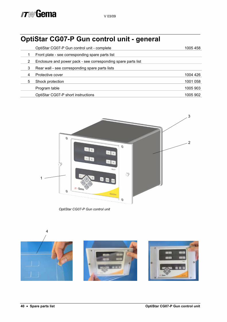
OptiStar CG07-P Gun control unit - general OptiStar CG07-P Gun control unit - complete 1005 458
1 Front plate - see corresponding spare parts list
2 Enclosure and power pack - see corresponding spare parts list
3 Rear wall - see corresponding spare parts lists
4 Protective cover 1004 426
5 Shock protection 1001 058
Program table 1005 903
OptiStar CG07-P short instructions 1005 902
OptiStar CG07-P Gun control unit
3
2
1
4

V 03/09
OptiStar CG07-P Gun control unit Spare parts list • 41
OptiStar CG07-P - inside rear wall 1 Throttle motor - complete 1000 064
4 Elbow joint - 1/8"a, Ø 6 mm 254 061
5 Fluidizing pad - 1/8"a 237 264
6 T-piece - 1/4"i-1/4"a-1/4"i 262 064
7 Solenoid valve - 1/4" (3/8"), NW11,5 - 24V 262 455
9 Elbow joint - 1/4", Ø 6 mm, 2x2 1001 933
11 Plastic tube - Ø 6/4 mm 103 144*
12 Plug - Ø 6 mm 251 925
13 Valve cable - CG07-P 1001 410
14 DPP01 interface 1004 144
15 Elbow joint - 1/4"a, Ø 6 mm 265 691
* Please indicate length
OptiStar CG07-P - inside rear wall
5
4
1
14
9
13
12
11
7
6
15
11

V 03/09
42 • Spare parts list OptiStar CG07-P Gun control unit
OptiStar CG07-P - outside rear wall 1 Rectus quick release connection - complete 1001 517
2 Hose connection - complete, Ø 6/4 mm 1001 520
3 Milled nut - M6 200 433
4 Shake proof washer - A-type, M6 200 450
5 Hexagon nut - M6 200 417
6 Washer - Ø 6.4/12.5x1.6 mm 200 476
7 Mains connection CG07-P 1001 176
8 Cap screw - M3x8 mm 202 363
9 Gun connection CG07-P 1001 179
10 Elbow joint - 1/4"i, Ø 8 mm 254 002
OptiStar CG07-P - outside rear wall
2
2
3
4
5
6 10
8 9 7
1

V 03/09
OptiStar CG07-P Gun control unit Spare parts list • 43
OptiStar CG07-P - enclosure and power pack 1 Enclosure - CG07-P Gun control unit 1001 435
2 Power pack - 15 VDC 374 059
3 Power pack power supply 1000 388
4 Mainboard power supply 1001 178
5 Spacer - Ø 4, Ø 4.8/4.8 mm, PA 263 508
6 Fuse - 4 AF 262 897
OptiStar CG07-P - enclosure and power pack
5
2
4
3
1
6

V 03/09
44 • Spare parts list OptiStar CG07-P Gun control unit
OptiStar CG07-P - front plate Front plate - complete 1005 445
1 Front plate with foil keyboard 1000 394
3 OptiStar mainboard - complete, with display 1004 867
4 Locknut - M3 262 498
5 Washer - Ø 3.2/7x0.5 mm 201 944
6 Spacer sleeve - Ø 3.2/6x6 mm 1001 925
7 Spacer sleeve - Ø 3.2/6x15 mm 1001 926
8 Compression spring - 0.5x6.3x13.5 mm 230 251
9 Special screw 1000 400
EPROM (not shown) 1004 868
OptiStar CG07-P - front plate
1
3
4
5
6
7
8
9

V 03/09
OptiStar CG07-P Gun control unit Spare parts list • 45
Diffuser Diffuser - complete 1005 263
1 Adaptor piece 1005 260
2 Fluidizing tube 1005 262
3 O-ring - Ø 19x1.5 mm 1005 749
4 Connector 1005 261
5 O-ring - Ø 12x1.5 mm 1000 822
6 Elbow joint - 1/8"a, Ø 6 mm 254 061
OptiSpray F Manual coating equipment - diffuser
1
3
2
4
5
6