Hitch & Drawbar Parts - Tractor Parts-Combine Parts-Farm Equipment

Operating Instructions and Parts Manual Tenoning Jig Model: JTG-10Q
WMH TOOL GROUP 2420 Vantage Drive Elgin, Illinois 60123 Part No. M-708295 Ph.: 800-274-6848 Revision A 10/04 www.wmhtoolgroup.com Copyright © WMH Tool Group
This Manual is Bookmarked

2
This manual has been prepared for the owner and operators of a JTG-10Q Tenoning Jig. Its purpose, aside from machine operation, is to promote safety through the use of accepted correct operating and maintenance procedures. Completely read the safety and maintenance instructions before operating or servicing the machine. To obtain maximum life and efficiency from your JET/Powermatic Tenoning Jig, and to aid in using the machine safely, read this manual thoroughly and follow instructions carefully.
Warranty WMH Tool Group warrants every product it sells. If one of our tools needs service or repair, one of our Authorized Repair Stations located throughout the United States can give you quick service.
In most cases, any one of these WMH Tool Group Repair Stations can authorize warranty repair, assist you in obtaining parts, or perform routine maintenance and major repair on your JET, Performax, Wilton, or Powermatic tools.
For the name of an Authorized Repair Station in your area, please call 1-800-274-6848, or visit www.wmhtoolgroup.com
More Information WMH Tool Group is consistently adding new products to the line. For complete, up-to-date product information, check with your local WMH Tool Group distributor, or visit www.wmhtoolgroup.com
WMH Tool Group Warranty WMH Tool Group (including JET, Wilton and Powermatic brands) makes every effort to assure that its products meet high quality and durability standards and warrants to the original retail consumer/purchaser of our products that each product be free from defects in materials and workmanship as follow: 1 YEAR LIMITED WARRANTY ON ALL PRODUCTS UNLESS SPECIFIED OTHERWISE. This Warranty does not apply to defects due directly or indirectly to misuse, abuse, negligence or accidents, normal wear-and-tear, repair or alterations outside our facilities, or to a lack of maintenance.
WMH TOOL GROUP LIMITS ALL IMPLIED WARRANTIES TO THE PERIOD SPECIFIED ABOVE, FROM THE DATE THE PRODUCT WAS PURCHASED AT RETAIL. EXCEPT AS STATED HEREIN, ANY IMPLIED WARRANTIES OR MERCHANTIBILITY AND FITNESS ARE EXCLUDED. SOME STATES DO NOT ALLOW LIMITATIONS ON HOW LONG THE IMPLIED WARRANTY LASTS, SO THE ABOVE LIMITATION MAY NOT APPLY TO YOU. WMH TOOL GROUP SHALL IN NO EVENT BE LIABLE FOR DEATH, INJURIES TO PERSONS OR PROPERTY, OR FOR INCIDENTAL, CONTINGENT, SPECIAL, OR CONSEQUENTIAL DAMAGES ARISING FROM THE USE OF OUR PRODUCTS. SOME STATES DO NOT ALLOW THE EXCLUSION OR LIMITATION OF INCIDENTAL OR CONSEQUENTIAL DAMAGES, SO THE ABOVE LIMITATION OR EXCLUSION MAY NOT APPLY TO YOU.
To take advantage of this warranty, the product or part must be returned for examination, postage prepaid, to an Authorized Repair Station designated by our office. Proof of purchase date and an explanation of the complaint must accompany the merchandise. If our inspection discloses a defect, we will either repair or replace the product, or refund the purchase price if we cannot readily and quickly provide a repair or replacement, if you are willing to accept a refund. We will return repaired product or replacement at WMH Tool Group’s expense, but if it is determined there is no defect, or that the defect resulted from causes not within the scope of WMH Tool Group’s warranty, then the user must bear the cost of storing and returning the product. This warranty gives you specific legal rights; you may also have other rights, which vary from state to state.
WMH Tool Group sells through distributors only. WMH Tool Group reserve the right to effect at any time, without prior notice, those alterations to parts, fittings, and accessory equipment, which they may deem necessary for any reason whatsoever.
3
Table of Contents Warranty........................................................................................................................................................2 Warnings .......................................................................................................................................................4 Shipping Contents.........................................................................................................................................6
Box Contents .............................................................................................................................................6 Required Tools ..........................................................................................................................................6
Assembly.......................................................................................................................................................7 Alignment ......................................................................................................................................................7 Operation.......................................................................................................................................................9 Angle Tenons ..............................................................................................................................................10 Parts ............................................................................................................................................................10
Replacement Parts ..................................................................................................................................10 Parts List..................................................................................................................................................11 Exploded View.........................................................................................................................................12
The specifications in this manual are given as general information and are not binding. WMH Tool Group reserves the right to effect, at any time and without prior notice, changes or alterations to parts, fittings, and accessory equipment deemed necessary for any reason whatsoever.
4
Warnings
1. Read and understand the entire owners manual before attempting assembly or operation.
2. Read and understand the warnings in this manual. Failure to comply with all of these warnings may cause serious injury.
3. The table saw and tenoning jig is designed and intended for use by properly trained and experienced personnel only. If you are not familiar with the proper and safe operation of a table saw or tenoning jig, do not use until proper training and knowledge have been obtained.
4. Do not use the tenoning jig for other than its intended use. If used for other purposes, WMH Tool Group disclaims any real or implied warranty and holds itself harmless from any injury that may result from that use.
5. Always wear approved safety glasses/face shields while using this tenoning jig. Everyday eyeglasses only have impact resistant lenses; they are not safety glasses.
6. Before operating the tenoning jig, remove tie, rings, watches and other jewelry, and roll sleeves up past the elbows. Remove all loose clothing and confine long hair. Non-slip footwear or anti-skid floor strips are recommended. Do not wear gloves.
7. Wear ear protectors (plugs or muffs) during extended periods of machine operation.
8. Some dust created by power sanding, sawing, grinding, drilling and other construction activities contain chemicals known to cause cancer, birth defects or other reproductive harm. Some examples of these chemicals are:
• Lead from lead based paint. • Crystalline silica from bricks, cement and other masonry products. • Arsenic and chromium from chemically treated lumber. 9. Your risk of exposure varies, depending on how often you do this type of work. To reduce your
exposure to these chemicals, work in a well-ventilated area and work with approved safety equipment, such as face or dust masks that are specifically designed to filter out microscopic particles.
10. Do not operate this jig while tired or under the influence of drugs, alcohol or any medication.
11. Make certain the table saw or shaper switch is in the OFF position before attaching the tenoning jig.
12. Make certain the machine is properly grounded.
13. Make all machine adjustments or maintenance with the machine unplugged from the power source.
14. Remove adjusting keys and wrenches. Form a habit of checking to see that keys and adjusting wrenches are removed from the machine before turning it on.
15. Keep safety guards in place at all times when the machine is in use. If removed for maintenance purposes, use extreme caution and replace the guards immediately.
16. Make sure the table saw or shaper is firmly secured to the floor or bench before use.
17. Check damaged parts. Before further use of the machine, a guard or other part that is damaged should be carefully checked to determine that it will operate properly and perform its intended function. Check for alignment of moving parts, binding of moving parts, breakage of parts, mounting and any other conditions that may affect its operation. A guard or other part that is damaged should be properly repaired or replaced.
18. Provide for adequate space surrounding work area and non-glare, overhead lighting.
19. Keep the floor around the machine clean and free of scrap material, oil and grease.
20. Keep visitors a safe distance from the work area. Keep children away.

5
blah blah blah
21. Make your workshop child proof with padlocks, master switches or by removing starter keys.
22. Give your work undivided attention. Looking around, carrying on a conversation and “horse-play” are careless acts that can result in serious injury.
23. Maintain a balanced stance at all times so that you do not fall or lean against saw blades, shaper cutters or other moving parts. Do not overreach or use excessive force to perform any machine operation.
24. Use the right tool at the correct speed and feed rate. Do not force a tool or attachment to do a job for which it was not designed. The right tool will do the job better and safer.
25. Use recommended accessories; improper accessories may be hazardous.
26. Maintain tools with care. Keep saw blades or shaper cutters sharp and clean for the best and safest performance. Follow instructions for lubricating and changing accessories.
27. Make sure the work piece is securely attached or clamped to the jig. Never use your hand to hold the work piece.
28. Turn off the machine before cleaning. Use a brush or compressed air to remove chips or debris — do not use your hands.
29. Do not stand on the machine. Serious injury could occur if the machine tips over.
30. Never leave the machine running unattended. Turn the power off and do not leave the machine until it comes to a complete stop.
31. Remove loose items and unnecessary work pieces from the area before starting the machine.
Familiarize yourself with the following safety notices used in this manual:
This means that if precautions are not heeded, it may result in minor injury and/or possible machine damage.
This means that if precautions are not heeded, it may result in serious injury or possibly even death.
- - SAVE THESE INSTRUCTIONS - -

6
Shipping Contents Open shipping carton and check that all parts are intact. Report any damage immediately to your distributor. Read the instruction manual thoroughly for assembly, alignment, maintenance and safety instructions.
Model Number.................................................................................................................................. JTG-10Q Stock Number ..................................................................................................................................... 708295
Box Contents A 1 ea Fence assembly B 1 ea Handwheel Assembly C 1 ea Clamp bracket D 2 ea Handles E 2 ea Socket Head Cap Screws (M10x25) F 1 ea Lock washers (M10)
Note: Exposed metal parts have been given a protective coating at the factory. This should be removed with a solvent, such as mineral spirits. Do not use an abrasive pad.
Required Tools G 1 set hex wrenches (3, 4, 8mm) provided

7
Assembly Refer to Figure 1.
1. Insert the handwheel assembly (F) into the clamp bracket (B) and secure with the lock handle (A) on the clamp bracket.
2. Attach the clamp bracket (B) to the back of the fence (G) using two M10 x 25 socket head cap screws (D) and M10 lock washers (E).
3. Attach the handles (C) to the clamp bracket (B).
Note: There are two slots on the underside of the tenoning jig. For the JTSA-10XL, 66 and 64A JET & Powermatic left tilt saws, mount the slide (H) into the left slot (farthest from the fence). A 4 mm hex wrench (provided) is required.
Alignment
Disconnect saw from power source before making adjustments to the tenoning jig.
To align the tenoning jig:
1. Place the jig guide into the saw's left miter gauge slot.
2. Using a square (A, Fig. 2), check to see if the fence is 90 degrees to the saw table. To make an adjustment to the fence, loosen the lock handle (B), adjust the fence to the 90-degree position and tighten lock handle.
3. When the fence is 90 degrees to the table, tighten setscrew (C) until it bottoms. See Figure 2. Setscrew (C) acts as a positive stop and allows you to quickly position the fence back to the 90-degree position after it has been tilted.
Figure 1
Figure 2

8
4. Using a square (A, Fig. 3), check to see if the position of the backstop (D) is 90 degrees to the saw table. If not, loosen the lock handle (E), adjust the backstop to the 90-degree position, and tighten the lock handle.
5. When the backstop is 90 degrees to the table, adjust the setscrew (F) until it touches the backstop. Tighten the jam nut. Setscrew (F) acts as a positive stop and allows you to quickly position the backstop back to the 90-degree position after it has been tilted.
6. Loosen locking handle (G, Fig. 4). Loosen thumbscrew (H) and move bracket (J) to the back edge of the guide rod (K). The guide bushing should move out with the bracket. If the guide bushing does not move lubricate with a light oil. Tighten locking handle (G), and thumb screw (H).
7. To bring the fence into parallel with the saw blade, loosen both locking handles (G, L). See Figure 4. Reposition the jig so that the fence lies flat against the saw blade and tighten both locking handles.
8. The miter bar slots in the base are milled to be parallel to the fence. If an adjustment is necessary, loosen the two hex socket head screws (A) holding the guide rod to the base, as shown in Figure 5. Place the jig back into the miter slot. Loosen locking handle (L Figure 4) and make the needed adjustment. When adjustment is finished, tighten the handle and remove the jig, and fully tighten the screws under the guide rod. Place the jig back on the saw with the miter bar in the miter slot.
9. Loosen both locking handles (G & L, Fig. 4), and back off jig so that the fence is approximately 1/8" away from the saw blade and tighten both locking handles (G & L).
Figure 3
Figure 4
Figure 5

9
10. To prevent the fence from being pushed, or moved, into the blade, loosen the nut (N) on the setscrew and turn the setscrew clockwise until it bottoms out (Figure 6). Tighten down the nut.
11. For a final adjustment, loosen screw (P) holding the pointer and adjust pointer to the 1/8" position. See Figure 7. Tighten screw.
Operation Use of the tenoning jig
requires removal of the table saw's blade guard. After the jig operation is complete, disconnect saw from power source and re-install the blade guard immediately.
1. Use the handwheel (A) to tighten your workpiece against the fence. See Figure 8.
2. Use the two large handles (B) to securely move the workpiece through the saw blade.
3. NOTE: Never pass the jig back over the moving saw blade. Wait until the power is off and the blade comes to a complete stop.
4. For rapid or large adjustments moving the fence toward or away from the saw blade, loosen both locking levers (C, D). Move the fence into position and tighten both locking levers (C, D).
5. For fine adjustments moving the fence toward or away from the saw blade, loosen both lock levers (C & D). Move the fence away from the saw blade and tighten lock lever (D) only. Move the fence into position with knob (E) and then tighten lock lever (C).
Figure 6
Figure 7
Figure 8

10
6. If it is necessary to cut a tenon on the side of the workpiece that is against the fence, a wood spacer must be secured between the workpiece and the fence, as shown in Figure 9. This will keep the saw blade from hitting the fence.
Note: There are four holes in the fence for mounting a wood block spacer.
Angle Tenons
For angle tenons, loosen lock lever (F), shown in Figure 10, and adjust the backstop (G) to the desired angle. Re-tighten lock lever (F).
Figure 11 shows an angle tenon procedure with the fence tilted. Loosen lock lever (H) to tilt the fence.
This type of cut requires a spacer (J) between the workpiece and the fence in order to prevent the saw blade coming into contact with the fence.
Figure 9
Figure 10
Figure 11
Parts Replacement Parts Replacement parts are listed on the following pages. To order parts or reach our service department, call 800-274-6848 between 7:00 a.m. and 6:00 p.m. (CST), Monday through Friday. Having the Model Number and Serial Number of your machine available when you call will allow us to serve you quickly and accurately.
11
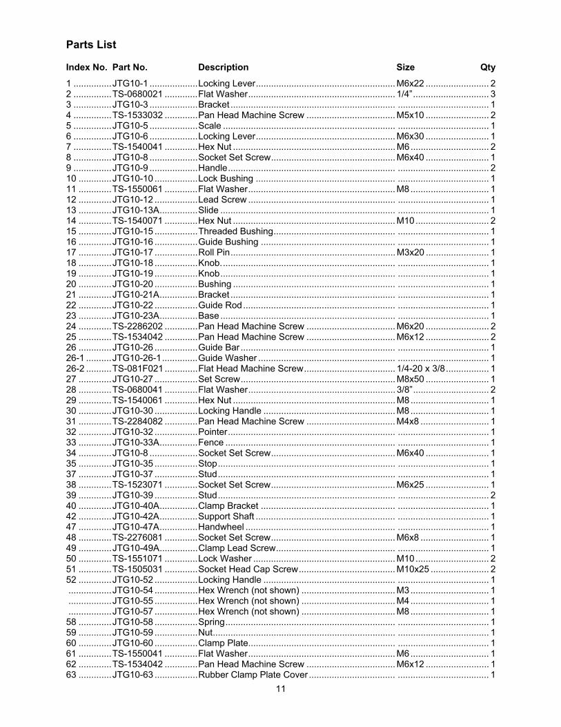
Parts List
Index No. Part No. Description Size Qty 1 ...............JTG10-1 ...................Locking Lever....................................................... M6x22 ......................... 2 2 ...............TS-0680021 .............Flat Washer.......................................................... 1/4”.............................. 3 3 ...............JTG10-3 ...................Bracket ................................................................. .................................... 1 4 ...............TS-1533032 .............Pan Head Machine Screw ................................... M5x10 ......................... 2 5 ...............JTG10-5 ...................Scale .................................................................... .................................... 1 6 ...............JTG10-6 ...................Locking Lever....................................................... M6x30 ......................... 1 7 ...............TS-1540041 .............Hex Nut ................................................................ M6............................... 2 8 ...............JTG10-8 ...................Socket Set Screw................................................. M6x40 ......................... 1 9 ...............JTG10-9 ...................Handle.................................................................. .................................... 2 10 .............JTG10-10 .................Lock Bushing ....................................................... .................................... 1 11 .............TS-1550061 .............Flat Washer.......................................................... M8............................... 1 12 .............JTG10-12 .................Lead Screw .......................................................... .................................... 1 13 .............JTG10-13A...............Slide ..................................................................... .................................... 1 14 .............TS-1540071 .............Hex Nut ................................................................ M10............................. 2 15 .............JTG10-15 .................Threaded Bushing................................................ .................................... 1 16 .............JTG10-16 .................Guide Bushing ..................................................... .................................... 1 17 .............JTG10-17 .................Roll Pin................................................................. M3x20 ......................... 1 18 .............JTG10-18 .................Knob..................................................................... .................................... 1 19 .............JTG10-19 .................Knob..................................................................... .................................... 1 20 .............JTG10-20 .................Bushing ................................................................ .................................... 1 21 .............JTG10-21A...............Bracket ................................................................. .................................... 1 22 .............JTG10-22 .................Guide Rod............................................................ .................................... 1 23 .............JTG10-23A...............Base ..................................................................... .................................... 1 24 .............TS-2286202 .............Pan Head Machine Screw ................................... M6x20 ......................... 2 25 .............TS-1534042 .............Pan Head Machine Screw ................................... M6x12 ......................... 2 26 .............JTG10-26 .................Guide Bar ............................................................. .................................... 1 26-1 ..........JTG10-26-1..............Guide Washer ...................................................... .................................... 1 26-2 ..........TS-081F021 .............Flat Head Machine Screw.................................... 1/4-20 x 3/8................. 1 27 .............JTG10-27 .................Set Screw............................................................. M8x50 ......................... 1 28 .............TS-0680041 .............Flat Washer.......................................................... 3/8”.............................. 2 29 .............TS-1540061 .............Hex Nut ................................................................ M8............................... 1 30 .............JTG10-30 .................Locking Handle .................................................... M8............................... 1 31 .............TS-2284082 .............Pan Head Machine Screw ................................... M4x8 ........................... 1 32 .............JTG10-32 .................Pointer.................................................................. .................................... 1 33 .............JTG10-33A...............Fence ................................................................... .................................... 1 34 .............JTG10-8 ...................Socket Set Screw................................................. M6x40 ......................... 1 35 .............JTG10-35 .................Stop...................................................................... .................................... 1 37 .............JTG10-37 .................Stud...................................................................... .................................... 1 38 .............TS-1523071 .............Socket Set Screw................................................. M6x25 ......................... 1 39 .............JTG10-39 .................Stud...................................................................... .................................... 2 40 .............JTG10-40A...............Clamp Bracket ..................................................... .................................... 1 42 .............JTG10-42A...............Support Shaft ....................................................... .................................... 1 47 .............JTG10-47A...............Handwheel ........................................................... .................................... 1 48 .............TS-2276081 .............Socket Set Screw................................................. M6x8 ........................... 1 49 .............JTG10-49A...............Clamp Lead Screw............................................... .................................... 1 50 .............TS-1551071 .............Lock Washer ........................................................ M10............................. 2 51 .............TS-1505031 .............Socket Head Cap Screw...................................... M10x25 ....................... 2 52 .............JTG10-52 .................Locking Handle .................................................... .................................... 1 .................JTG10-54 .................Hex Wrench (not shown) ..................................... M3............................... 1 .................JTG10-55 .................Hex Wrench (not shown) ..................................... M4............................... 1 .................JTG10-57 .................Hex Wrench (not shown) ..................................... M8............................... 1 58 .............JTG10-58 .................Spring................................................................... .................................... 1 59 .............JTG10-59 .................Nut........................................................................ .................................... 1 60 .............JTG10-60 .................Clamp Plate.......................................................... .................................... 1 61 .............TS-1550041 .............Flat Washer.......................................................... M6............................... 1 62 .............TS-1534042 .............Pan Head Machine Screw ................................... M6x12 ......................... 1 63 .............JTG10-63 .................Rubber Clamp Plate Cover .................................. .................................... 1

12
Exploded View