Operating Instructions - agroparts
47
LEMKEN GmbH & Co. KG Weseler Straße 5, D-46519 Alpen / Postfach 11 60, D-46515 Alpen Telefon (0 28 02) 81-0, Telefax (0 28 02) 81-220 E-Mail: [email protected], Internet: http://www.lemken.com Art.-Nr.: 175 3806 GB-1/09.04 SAFETY IS OUR CONCERN! Operating Instructions Cultivators Combi-Liner
Transcript of Operating Instructions - agroparts

Operating Instructions
Cultivators
Combi-Liner
LEMKEN GmbH & Co. KGWeseler Straße 5, D-46519 Alpen / Postfach 11 60, D-46515 Alpen
Telefon (0 28 02) 81-0, Telefax (0 28 02) 81-220E-Mail: [email protected], Internet: http://www.lemken.com
Art.-Nr.: 175 3806GB-1/09.04
SAFETY IS OUR CONCERN!

Dear customer!
We would like to thank you for the confidence in buying this implement.
The advantages of this implement will be shown, only, when operated andused with due care and attention.
When handing over this implement your dealer has already instructed youwith regard to operation, adjustment and maintenance. But this short intro-duction requires an additional detailed study of the instruction book.
Therefore read this instruction book carefully before the first use. Please payattention to the safety instructions mentioned in this instruction book.
Any changes and modifications carried out not being mentioned expressly inthis instruction book, may only be carried out with a written agreement of themanufacturer.
Ordering spare-parts
When ordering spare-parts please state type and serial No. of the implement.This information will be found on the identification plate.
Put down this data on the following table so that it is always available.
Only use genuine Lemken spare-parts. Spurious parts negatively influencethe function of the implement, show a shorter lifetime and increase in nearlyall cases additional maintenance.
We trust that you will understand that LEMKEN is unable to guarantee pooroperation and damage caused by using spurious parts!
Type of implement: ________________Fabrication No.: ___________________
1

2

DEFINED USE
• Please familiarise yourself with the LEMKEN Combi-Linerand its operations before putting the implement to work.Therefore use this instruction book with the „General Health-and Safety precautions“!
• The LEMKEN Combi-Liner have been designed purely for the agriculturaluse!
• Any use beyond the one stipulated above is no longer considered as defi-ned use!
• Under „defined use“ the manufacturer’s prescribed operation-, mainte-nance- and repair conditions are to be adhered to!
• The LEMKEN Combi-Liner may only be operated, maintained and re-paired by such persons who have been made acquainted with it and whohave been advised about the dangers!
• The applicable accident prevention advice as well as the generally accep-ted safety technical, working, medical and road traffic rules should be ad-hered to!
CONTENTS
DEFINED USE ........................................................................................ 3
CONTENTS ............................................................................................ 3
1 SAFETY INSTRUCTIONS ...............................................................7
2 WARNING STICKERS ..................................................................122.1 General Instructions ............................................................122.2 Understanding the stickers.................................................122.3 Position of the warning stickers.........................................14
3 PREPARATION OF TRACTOR ....................................................15
3

3.1 Tyres..................................................................................... 153.2 Check chains or sway blocks ............................................ 153.3 Lower link connection ........................................................ 153.4 Tractor hydraulics ............................................................... 153.5 Required power sources and sockets............................... 163.6 Required spool valves at the tractor ................................. 16
4 ATTACHING AND DETACHING .................................................. 174.1 Attaching.............................................................................. 174.2 Detaching............................................................................. 17
5 ADJUSTMENTS ............................................................................ 185.1 Working depth ..................................................................... 185.2 Pole....................................................................................... 195.3 Chassis................................................................................. 205.4 Tyres..................................................................................... 205.5 Depth control wheels .......................................................... 21
6 HYDRAULIC THREE POINT LINKAGE ....................................... 226.1 Attaching a seed drill .......................................................... 226.2 Lowering limiter................................................................... 236.3 Stop ...................................................................................... 236.4 Detaching a seed drill ......................................................... 23
7 TRACK MARKERS ....................................................................... 24
8 ADJUSTMENTS - RUBIN 9 Ü COMBI-LINER ............................. 268.1 Rebound harrow.................................................................. 268.2 Guide boards ....................................................................... 268.3 Side shields ......................................................................... 278.4 Side draw ............................................................................. 278.5 Depth adjustment for left hollow disc ............................... 288.6 Folding-in and -out the outer hollow discs....................... 29
4

8.6.1 Folding-in the outer hollow discs .................................298.6.2 Folding-out the outer hollow discs ...............................30
9 ADJUSTMENTS - THORIT 8 COMBI-LINER AND SMARAGD 9 COMBI-LINER ......319.1 Working depth of the tines..................................................319.2 Tine position.........................................................................319.3 Shares ...................................................................................329.4 Working depth adjustment of the hollow discs ................339.5 Outer discs ...........................................................................339.6 Shearbolt device .................................................................349.7 Automatic overload safety device......................................35
10 MAINTENANCE .............................................................................3610.1 Greasing table - Rubin.........................................................3710.2 Greasing table - Smaragd und Thorit.................................3710.3 Greasing table - Combi-Liner..............................................3710.4 Bolts ......................................................................................3810.5 Wearing parts .......................................................................3810.6 Hydraulic hoses ...................................................................38
11 DRIVING ON PUBLIC ROADS .....................................................3911.1 General Instructions ............................................................3911.2 Allowed transport speed .....................................................3911.3 Allowed axle load.................................................................39
12 TECHNICAL DATA .......................................................................40
13 NOISE, AIRBORNE SOUND .........................................................41
14 DISPOSAL .....................................................................................41
15 NOTES ...........................................................................................41
INDEX ................................................................................................... 43
5

EC CERTIFICATE OF CONFORMITY................................................. 45
6

1 SAFETY INSTRUCTIONSGeneral Safety Instructions
• Before using the machine, always check both it and the trac-tor for roadworthiness and operational safety!
• As well as the notes in these instructions the operator is ad-vised to comply with the generally applicable safety at workregulations and those relating to use of the public highway!
• The implement may only be operated, maintained and repaired by suchpersons who have been made acquainted with it and who have been ad-vised about the dangers!
• When driving on public roads with a raised machine the lifting control levershould be locked against unintentional lowering!
• The fitted warning and advisory plates give important information for safeoperation; adhering to these increases your own security!
• When using public roads adhere to applicable traffic rules!
• The operator should familiarise him-/herself with all controls and theirfunctions before starting work. During work could be too late!
• The clothing of the operator should fit tight. Avoid wearing any loose clot-hing!
• To avoid danger of fire keep the implement clean!
• Before beginning to drive check surroundings area (children)!
• Sitting or standing on the implement during operation or during transportis not permissible.
• Attach implements as advised and only to the stipulated positions!
• Special care should be taken when the implement is coupled to or uncou-pled from the tractor.
• When coupling or uncoupling the implement bring the supporting standsinto the corresponding position (standing safety)!
• Fit weights only to the fixing points provided for that purposes!
7
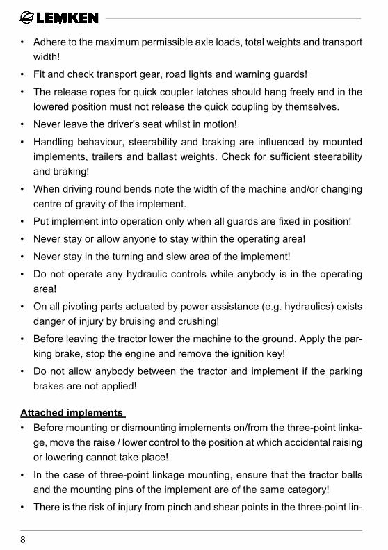
• Adhere to the maximum permissible axle loads, total weights and transportwidth!
• Fit and check transport gear, road lights and warning guards!
• The release ropes for quick coupler latches should hang freely and in thelowered position must not release the quick coupling by themselves.
• Never leave the driver's seat whilst in motion!
• Handling behaviour, steerability and braking are influenced by mountedimplements, trailers and ballast weights. Check for sufficient steerabilityand braking!
• When driving round bends note the width of the machine and/or changingcentre of gravity of the implement.
• Put implement into operation only when all guards are fixed in position!
• Never stay or allow anyone to stay within the operating area!
• Never stay in the turning and slew area of the implement!
• Do not operate any hydraulic controls while anybody is in the operatingarea!
• On all pivoting parts actuated by power assistance (e.g. hydraulics) existsdanger of injury by bruising and crushing!
• Before leaving the tractor lower the machine to the ground. Apply the par-king brake, stop the engine and remove the ignition key!
• Do not allow anybody between the tractor and implement if the parkingbrakes are not applied!
Attached implements • Before mounting or dismounting implements on/from the three-point linka-
ge, move the raise / lower control to the position at which accidental raisingor lowering cannot take place!
• In the case of three-point linkage mounting, ensure that the tractor ballsand the mounting pins of the implement are of the same category!
• There is the risk of injury from pinch and shear points in the three-point lin-
8

kage area!
• When operating the external lift controls for the three-point linkage, do notstand between the tractor and implement!
• Always ensure sufficient lateral limitation for the three-point linkage of thetractor in the transport position of the implement!
• When driving on roads with the implement raised, the raise/lower controlmust be locked to prevent lowering!
Mounted implements• Mount implements as advised and only to the advised devices!
• When mounting or detaching the implement bring the supporting devicesinto the corresponding position (standing safety)!
• Fit and check transport devices like traffic lights, warning guards and pro-tection devices!
• On all pivoting parts actuated by various power sources (e.g. hydraulics)exists danger of injury by bruising and crushing!
• Before mounting or detaching the implement the lifting control lever shouldbe locked against unintentional lowering or lifting!
• Special care should be taken when the implement is mounted or detachedfrom the tractor.
Trailed implements• Secure implement and tractor against unintended rolling!
• Never exceed the maximum permissible load of the drawbar or hitch!
• When fitting the implement to a drawbar or hitch, ensure sufficient move-ment at the hitch-point.
Hydraulic equipment• The hydraulic pipes are under pressure!
• When connecting hydraulic rams, the pipes must be connected as direc-
9

ted!
• Always release hydraulic pressure from both tractor and implement beforecoupling!
• When connecting hydraulic pipes to the tractor ensure that incorrect use isavoided. If the connections are reversed, the opposite function is carriedout (e.g. raising/lowering) and there is a risk of accidents!
• Regularly check the hydraulic pipes and replace them in the event of da-mage or signs of ageing. The replacement pipes must comply with thetechnical specification as laid down by Lemken!
• When searching for leaks appropriate equipment should be used becauseof the danger of injury!
• Hydraulic oil escaping at high pressure can penetrate the skin and causeserious injury! When injured see a doctor immediately! Danger of infection!
• Before working on any hydraulic equipment - lower all implements/attach-ments, release hydraulic pressure where possible and switch off the trac-tor engine!
Tyres• When working on the tyres make sure that the implement has been placed
on the ground safely and that it is secured by chocks against unintentionalrolling!
• Fitting tyres requires knowledge and special tools!
• Repairwork on tyres may only be conducted by trained staff and with sui-table tools!
• Check air pressure regularly and adhere to the advised air pressure!
Maintenance • Repair-, maintenance- and cleaning operations as well as adjustments
and remedy of function faults should principally be conducted with enginestopped and brakes applied. Remove ignition key!
10

• Check and tighten nuts and bolts regularly!
• When conducting maintenance work on a lifted implement always placesuitable supports underneath!
• For replacing any tools with cutting edges always use suitable tools andgloves!
• Dispose of old oils, grease and filters as prescribed by law.
• Before working on the electric gear disconnect battery cables!
• When conducting electrical welding operations on the tractor or on themounted implement remove cable from the generator and the battery!
• Any spare parts fitted must meet with the implement manufacturer's fixedtechnical standards! This is for example ensured by using genuine spareparts!
11

2 WARNING STICKERS
2.1 General Instructions
The LEMKEN Combi-Liner is equipped with all features to ensure safe ope-ration. Where potential danger areas of the implement can not be fully safe-guarded, warning stickers are fitted which draw attention to these. Damaged,lost or unreadable warning stickers must be replaced immediately. The statednumbers are used as order numbers.
2.2 Understanding the stickers
Familiarise with the meaning of the stickers. The following descriptions informabout them in detail.
WARNING! Read and adhere to this Instruction book andthese "General Health- and Safety precauti-ons", before putting the implement to work!
WARNING! Before maintenance and repair work, stoptractor engine and remove ignition key!
12

WARNING! Pinch point!
WARNING! Keep well clear of the foldingarea of the implement!
WARNING! Keep well clear of the workingand swinging area of the imple-ment!
13

2.3 Position of the warning stickers
14
3 PREPARATION OF TRACTOR
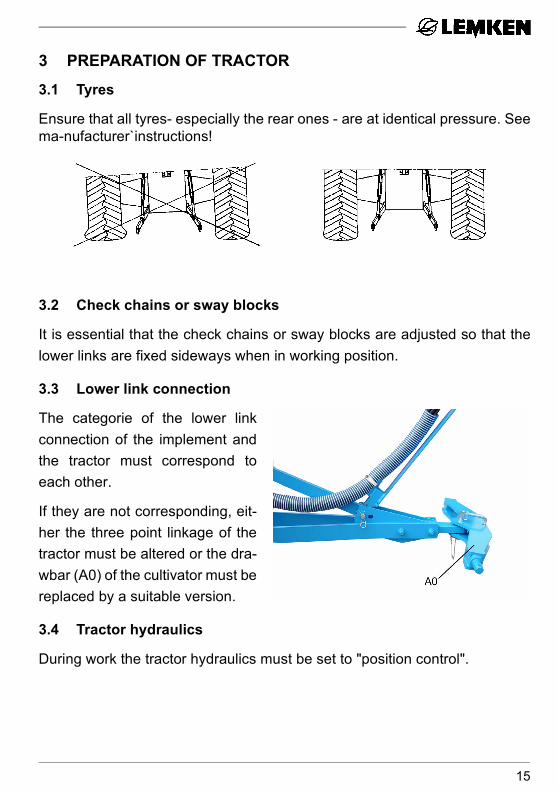
3.1 Tyres
Ensure that all tyres- especially the rear ones - are at identical pressure. Seema-nufacturer`instructions!
3.2 Check chains or sway blocks
It is essential that the check chains or sway blocks are adjusted so that thelower links are fixed sideways when in working position.
3.3 Lower link connection
The categorie of the lower linkconnection of the implement andthe tractor must correspond toeach other.
If they are not corresponding, eit-her the three point linkage of thetractor must be altered or the dra-wbar (A0) of the cultivator must bereplaced by a suitable version.
3.4 Tractor hydraulics
During work the tractor hydraulics must be set to "position control".
15

3.5 Required power sources and sockets
For the electric use of the Combi-Liner the following power sources must beavailable with the tractor.
The range of tolerances for the power supply is between 10 V and 15 V.
Excess voltage and undervoltage lead to a breakdown and can destroy elec-tric components.
Furthermore it must be ensured that there is a power covering of the powersupply of at least 25 A.
3.6 Required spool valves at the tractor
The Combi-Liner will be delivered with separate hydraulic hoses for each useas standard. For the operation of the listed devices, the following spool valvesare required with the tractor.
In combination with a seed drill with own hydraulic uses additional tractorspool valves are required. See operating instructions of the correspondingseed drill.
Function Voltage Direct connection to the battery
Socket
Lighting equipment 12 - according toDIN-ISO 1724
Electronic seed drill con-trol Solitronic or LH 5000 12 x -
Electronic seed drill con-trol Easytronic or LH 1600 12 - according to
DIN 9680
Function single acting spool valve
double acting spool valve
Tractor/Implement Colour Code
Chassis - x green P2T2
Track marker (option) x - black P4
Hydraulic three point linkage - x blue P3
T3
16

4 ATTACHING AND DETACHING
4.1 Attaching
- For attaching the Combi-Linerthe hydraulics of the tractormust be set to position control!
- Connect the tractor lower linksto the drawbar (A0) and secu-re! See also section „Pole“ ofthis operating manual.
- Connect hydraulic hoses!
- Connect electric cables.
WARNING! If an implement will be fitted or mounted to the Combi-Lineralso the instructions of the corresponding operators manualmust be adhered to!
4.2 Detaching
The cultivator must always be parked on level and firm ground!
- Set tractor hydraulics to position control before detaching the implement!
- Secure implement against rolling away!
- Disconnect electric cables!
- Lower the implement and disconnect the lower links from the drawbar(A0)!
- Stop engine and move the operation levers of the spool valve several ti-mes to and fro, in order to release the hydraulic hoses!
- Disconnect hydraulic hoses and fit protection cap!
T
• Read and adhere to the General Safety Instructions as wellas to the Instructions „Trailed implement“, „Mounted imple-ment“ and „Attached implement“!
17

5 ADJUSTMENTS
5.1 Working depth
The working depth of the Combi-Liner can be adjusted in front bymeans of the tractor hydraulicsand at the rear by means of theadjusting clamps (S1) of the hy-draulic rams (F2). Before the adjustment, the imple-ment must be lifted a few centime-ters via the hydraulic rams (F2).
The working depth can be adju-sted in 10 mm or 5 mm steps. Forthe adjustment in 5 mm steps thecorresponding adjusting clampmust be reversed.
Displace adjusting clamp (S1) tothe front = deeper working depth.Displace the adjusting clamp (S1)to the rear = shallower workingdepth.
The adjusting clamps must al-ways be displaced by the sameamount.
For work the implement must belowered until the adjusting clamps(S1) are touching the stops (V1).
18

5.2 Pole
The pole (AD) can be adjusted to a length of 180 cm and 210 cm.
The length of 180 cm can be chosen for tractors up to 350 cm width.
The length of 210 cm must be chosen when the tractor is wider than 350 cmor depth control wheels (J0) are fitted in front.
For changing the length the pole front part (AV9) in „long position“ must befitted to the front and outer side of the pole rear part (AH9) or in „short positi-on“ to the rear and inner side of the pole rear part (AH9).
With tractors up to 350 cm width => set pole to „short position“
With tractors from 350 cm width on => set pole to „long position“
In combination with depth control wheels => set pole to „long position“
After changing the length all bolts (AS) must be tightened again. The threadof the bolts must be provided with Loctite before screwing on the nuts.
19

5.3 Chassis
The chassis (F4) with the wheels(W0) in staggered position is usedas roller in working position and intransport position as transport de-vice.
At the rear of the chassis a hy-draulic three point linkage (N6)(catergory II) is provided for atta-ching an implement, e.g. a seeddrill.
5.4 Tyres
The chassis of the Combi-Liner is available with the tyres 185/65-15 and thedepth control wheels with the tyres 195R (650x198 mm) or 10.0/80-12(710x264 mm). Ply rate and profile description are printed in the tyre. Dama-ged or worn tyres must be re-placed immediately. The following minimum andmaximum air pressures must be adhered:
• Read and adhere to the General Safety Instructions as wellas to the Instructi-ons "Tyres"!
In connection with the tyres 12.5/80-18 it is not possible to fit aseed drill at the Combi-Liner!
Description Part No. Profile Ply-rating (PR)
min. allowed air pressure
(bar)
max. allowed air pressure
(bar)
185/65-15 550 8890(right) AS 4 1.5 2.5
185/65-15 550 8891(left) AS 4 1.5 2.5
195 R 15 549 8858 AW 4 1.5 2.310.0/80-12 549 8849 AW 8 2.0 4.0
20

5.5 Depth control wheels
As accessory depth controlwheels (J0) are available.
They prevent that the outer toolswork too deep.
They should not be loaded withtoo much weight of the cultivator.
The depth will be adjusted by me-ans of the pin adjuster (V2) andthe eccentric lever (J1).
Before dismounting the pin (J2), itmust be unloaded by means of theeccentric lever (J1). Therefore theeccentric lever will be fitted to oneof the holes (J3) of the wheel stalk(J4) directly above the bracket(J5), secured and pressed down.
WARNING! The weel stalk (J4)must always beheld by the eccentric lever (J1) or the pin (J2)! Never dismounteccentric lever and pin at the same time!
After each depth adjustment the pin (J2) must be secured again.
• Read and adhere to the General Safety Instructions as well
as to the Instructions „Hydraulic assembly“, „Tyres“ and„Maintenance“!
21

6 HYDRAULIC THREE POINT LINKAGE
6.1 Attaching a seed drill
A seed drill can be fitted to the hy-draulic three point linkage (N6),which is showing a headstock ofcategory II according to ISO 730.
A seed drill will be connected tothe hydraulic three point linkagevia its headstock and secured.See operators manual of the seeddrill concerned.
For attaching the LEMKEN seeddrill Saphir 7 AutoLoad couplingparts (KT) must be fitted to the fra-me (AR) instead of catchinghooks (KH). Then the top link ofthe hydraulic three point linkagewill be exchanged for a top cat-ching hook (FH). See operatorsmanual of the LEMKEN seed drillSaphir 7 AutoLoad.
After attaching both the top andthe lower fitting points must be se-cured.
22

6.2 Lowering limiter
The working depth of the attachedimplement respectively the lowe-ring depth of the links (U1) will beadjusted via the pin adjustment(U2) by means of the pin (U3).Fit pin (U3) in a higher position -> less lowering depthFit pin (U3) in a deeper position -> deeper lowering depth
The required lowering depth depends on the attached implement. See ope-rators manual of the corresponding attached implement.
6.3 Stop
The maximum lifting height is limited by the stops (U4). The stops must beadjusted so that the left and right links (U1) are parallel to each other. In com-bination with a hydraulic three point linkage connected single acting, thestops must be turned out until it is possible to lower the hydraulic three pointlinkage with attached implement without standstill or dead point position.
6.4 Detaching a seed drill
Prepare seed drill so that the drill can be parked safely. - Lower the seed drill and disconnect all supply hoses and cables! See ope-
rators manual of the corresponding seed drill!- Disconnect frame (AR) with top connection point respectively top catching
hook (FH) and lower catching hook (KH) respectively coulpling parts (KT)from the seed drill.
- Lower three point linkage and drive away carefully with the Combi-Linerfrom the seed drill.
• Read and adhere to the General Safety Instructions!• Read and adhere also the instructions book of the seed drill
manufacturer!
23

7 TRACK MARKERSBefore operating the track mark-ers (SP1), they must be unlockedand adjusted.
Therefore the pins (SP3) must beremoved and fit between the hy-draulic ram (SP5) and track mar-ker arm (SP7) and secured.
Via the hydraulic rams (SP5) thetrack markers will alternatetly belifted and lowered into working po-sition.
The track markers must be adju-sted to the centre of the tractortrack according to the following ta-ble.
After loosening the clamp screws(SP6) the length of the track mar-ker arm (SP7) and the angle of thetrack marker discs (SP8) can beadjusted.
After the adjustment the corre-sponding clamp screws (SP6) willbe tightened again carefully.
For transport, the track markerarms (SP7) must be swung-in and secured by means of the hydraulic rams(SP4). The hydraulic ram is positioned then between pin (SP3) and track mar-ker arm (SP7).
Track marker (SP1) in working position. The pin (SP3) is positioned between hydraulic ram - (SP5) and track marker arm (SP7).
24

The track markers are protectedagainst overload by means of ashear bolts (SP0).
• Read and adhere to the General Safety Instructions as wellas to the Instructions „Hydraulic assembly“!
Working width Distance from the centre of the seed drill to the track marking
Distance from the outer see-ding coulter to the row gap
300 cm 300 cm 150 cm + 1/2 row distance400 cm 400 cm 200 cm + 1/2 row distance
25

8 ADJUSTMENTS - RUBIN 9 Ü COMBI-LINER
8.1 Rebound harrow
The rebound harrow (P0) can beadjusted either in a distance to thehollow discs as well as in height.The deeper and the closer theharrow is positioned to the hollowdiscs, the better the levelling eff-fect.
By means of the pin adjuster (V2)the rebound harrow (P0) can beadjusted individually and that in height and distance to the hollow discs bymeans of the pin (P2).
With the pins (P3) and (P4) the rebound harrow will be fixed in its position.The row of holes (P5) must be set always approximately vertically to theground.
8.2 Guide boards
The guide boards (L1) which areadjustable in an angle as well asin height, are used for filling thegroove made by the left hollowdisc with soil of the rear row. Bymeans of the clamp screw (L2) theguide boards can be set indivi-dually. They should be positioneda little deeper than the harrow ti-nes (P1).
26

8.3 Side shields
The side shields (R0) prevent thatthe outer right hand rear hollowdisc and the left hand front hollowdisc leave a groove or that damswill be formed. They are fitted late-ral moveable with each carrier(R1) to the frame (R2) by meansof clamp screws (R3). By meansof the clamp device (V4), they firstcan be set to front and rear andsecond adjusted in depth and angle. The basic adjustment by the factory is:
1. 5° oblique positioned and2. fitted in the middle position to the carrier (R1).
During work the left side shield shall be set approximately 23 cm and the rightside shield approximately 14 cm above the ground surface.
8.4 Side draw
The front and rear oblique positioned hollow discs create opposite sideforces, which are compensated. If there is still lateral draw noticable, it can beeliminated as follows:
Side draw to the right => Lift tractor hydraulic a little
Side draw to the left => Lower tractor hydraulic a little
27

8.5 Depth adjustment for left hollow disc
The working depth of the left hol-low disc can be adjusted a little bitshallower than the other hollowdiscs by means of the off-centreadjuster (TX).
Therewith it will be prevented thatthe left rear hollow disc works toodeeply and leaves a groove be-hind, which cannot be levelled bythe guide boards (L1).
For the adjustment the screw (SX) must be loosened, the off-centre adjuster(TX) adjusted as required and finally tighten the screw (SX) carefully.
28

8.6 Folding-in and -out the outer hollow discs
8.6.1 Folding-in the outer hollow discs
For transport the outer hollow discs (K3) must be folded-in as follows:
- Unlock and dismount lockingpin (K4).
- Pull up lever (K5) and swing itdownwards.
- Move up lever (K5) until theslotted hole (K6) is visible abo-ve the holder (K7) and the ex-pansion pin (K8) is locked intothe recess (K9).
- Now the corresponding outerhollow disc can be folded-inmanually.
- After that the locking pin mustbe fit into the free hole (K10)and secured to prevent an un-intentional folding-out of theouter hollow discs.
29
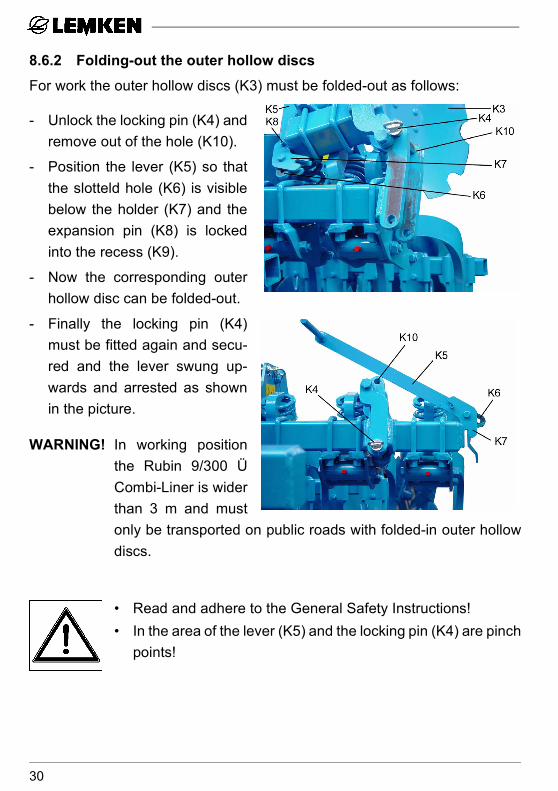
8.6.2 Folding-out the outer hollow discs
For work the outer hollow discs (K3) must be folded-out as follows:
- Unlock the locking pin (K4) andremove out of the hole (K10).
- Position the lever (K5) so thatthe slotteld hole (K6) is visiblebelow the holder (K7) and theexpansion pin (K8) is lockedinto the recess (K9).
- Now the corresponding outerhollow disc can be folded-out.
- Finally the locking pin (K4)must be fitted again and secu-red and the lever swung up-wards and arrested as shownin the picture.
WARNING! In working positionthe Rubin 9/300 ÜCombi-Liner is widerthan 3 m and mustonly be transported on public roads with folded-in outer hollowdiscs.
• Read and adhere to the General Safety Instructions!• In the area of the lever (K5) and the locking pin (K4) are pinch
points!
30

9 ADJUSTMENTS - THORIT 8 COMBI-LINER AND SMARAGD 9 COMBI-LINER
9.1 Working depth of the tines
See section „Working depth“.
9.2 Tine position
The tine position respectively theshares of the implement can be al-tered. A flat share position redu-ces the traction requirement; asteep share position ensures agood penetration, even in hardand dry soil conditions.
The tine (H0) position and thus theposition of the point (H2) will be al-tered by repositioning the shearbolt (H1).
Hole A = flat position (especially for heavy sticky soils = easier to pull)Hole B = steep position (especially for dry and hard conditions = improvedpenetration)
31

9.3 Shares
The Thorit 8 Combi-Liner is available with points S8P (80 mm wide) or S12 P(120 mm wide). These points will be bolted to the sahre foot 10-S.
Also for the Smaragd 9 Combi-Liner as well as for the Thorit 8 Combi-Lineralso change wing shares are available with points and wing shares, which willbe bolted to the foot 10-S/FL. This foot is provided with additonal holders forthe wing shares.
If it is required to work deep, it will be recommended to use share points S8Pwith foot 10-S; if it is required to work over the complete width and shallow,use change wing shares. (With the Smaragd 9 Combi-Liner they are as stan-dard).
32

9.4 Working depth adjustment of the hollow discs
The working depth of the hollow di-scs can be adjusted roughly via thepin adjustment (V6) and fine via thepin adjustment (V4).The hollow discs (K3) should beadjusted so deep that they level theridges and grooves left by the reartines. When working too deep, newridges and grooves will be built,and when working too shallow, thegrooves and ridges left by the tineswill be levelled insufficiently.
9.5 Outer discs
The outer discs (R0) will be bolted to the ends of the hollow disc carriers viaits frame tube. They should not work so deep as the inner hollow discs (K3); their purpose isonly to move the soil which has been thrown beyond the working width, intothe grooves left by the outer tines. After having loosened the clamping bolts(R1) the outer discs can be moved laterally so that they always move backthe soil which has been thrown to the outside.Working depth adjustment can be made by means of the pin adjuster (V4).For transport on public roads, theouter discs must be folded-in. Forfolding-in each pin (R8) must beunlocked and removed, the outerdisc folded-in and secured in fol-ded-in position by means of thepins (R8). Finally the pin (R8)must also be secured. On the field- before use - the outer discs mustbe folded-out and secured again.
33

9.6 Shearbolt device
Each tine (H0) and disc carrier is fitted with a shearbolt (H1) which will protectcultivator, tines, the share points (H2) and discs against overload.
Replace sheared bolt (H1) as follows:
a) Raise cultivator a few cm.
b) Remove all remains of the shearbolt.
c) Swing tine and/or disc carrier back into position.
d) Fit new shearbolt into hole concerned and tighten carefully.
Only shearbolts according to the schedule below should be used. Otherwisethere is a serious risk of damage to frame, tine or disc carrier or a prematurefailure may be experienced.
Combi-Liner Tines Disc carrier with shearbolt device
Thorit 8 and Smaragd 9
301 7342 M12 x 65 B = 15/8.8
301 3240 M10 x 45 B = 10/8.8
Thorit 8 Ü and Smaragd 9 Ü
301 3391M12 x 60 B = 15/10.9
301 3240M10 x 45 B = 10/8.8
34

9.7 Automatic overload safety device
The tines (H0) of the cultivator isequipped with an automatic over-load safety device which is espe-cially designed for stony soilconditions.
The tines trip back and upwardswhen touching an obstacle andautomatically return to the wor-king position once the obstaclehas been passed.
The cultivator is additionally pro-tected by means of shearbolts (H1).
As option also the pairs of hollow discs (K3) and the outer discs (R0) areavailable with automatic overload safety device.
• Read and adhere to the General Safety Instructions!• Coil springs are under load!• The tines trip to the rear and upwards!
35
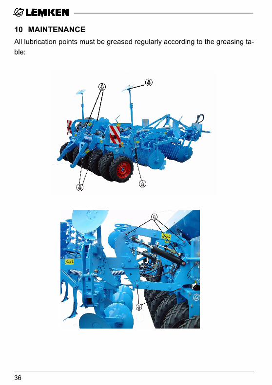
10 MAINTENANCEAll lubrication points must be greased regularly according to the greasing ta-ble:
36

10.1 Greasing table - Rubin
10.2 Greasing table - Smaragd und Thorit
10.3 Greasing table - Combi-Liner
every 50 hours of
use
every 100 hours of
use
before the winter break
after the winter break
Pivot bearings of the over-load safety device x x x
Grease all areas of the hol-low discs, outer discs and guide boards
x
every 50 hours of
use
every 100 hours of
use
before the winter break
after the winter break
Overload safety device (each 2x) x x x
Hollow discs (each 1x) x x x
Grease pins x x
Grease all areas of the hol-low discs, outer discs and guide boards x
every 50 hours of
use
every 100 hours of
use
before the winter break
after the winter break
Hydr. three point linkage (6x) x x x
Chassis (10x) x x x
Bearing of the track marker discs (2x) x x x
Grease pins x x
Grease piston rod with non-acid grease x
37

10.4 Bolts
All nuts and bolts must be tightened after the first few hours of use, at leastwithin the first 8 hours and checked, and tightened if necessary. At least every50 hours all bolts must be checked and tightened if necessary and securedwith Loctite.
10.5 Wearing parts
Worn shares, hollow discs, outer discs a.s.o. must be replaced in time, so thatthe carrying parts will not be damaged or worn.
10.6 Hydraulic hoses
Regularly check the hydraulic hoses with regard to damage and leaks. Repla-ce any that are defective. All hydraulic hoses must be exchanged after 6years. Use genuine replacement parts, only.
IMPORTANT: Do not clean this implement with a Pressure Washer duringthe first 6 weeks. After this time a minimum nozzle distance of60 cm must be observed with a maximum 100 bar pressureand 50° C temperature.
• Read and adhere to the General Safety Instructions as well asto the Instructions 'Maintenance'!
38

11 DRIVING ON PUBLIC ROADS
11.1 General Instructions
The prescribed lighting equipment and warning boards are standard with theCombi-Liner.
With shallow working depth adjustment the Rubin 9 KÜ is wider than 3 m.Therefore when driving on public roads the maximum working depth must beadjusted and fixed.
11.2 Allowed transport speed
The maximum allowed transport speed amounts to 30 km/h.
11.3 Allowed axle load
The maximum allowed axle load amounts to 3000 kg.
39

12 TECHNICAL DATA
Rubin 9 Ü Combi-LinerWorking width 3 m 4 mmaximum allowed axle load 3000 kg 3000 kgmaximum support load 2000 kg 2000 kgtransport width (cm) 300 cm 400 cmworking width (cm) 300 cm 400 cmup to KW (PS) 110 (150) 132 (180)weight (kg) 2620 kg 2980 kg
Smaragd 9 Combi-LinerWorking width 3 m 4 mmaximum allowed axle load 3000 kg 3000 kgmaximum support load 2000 kg 2000 kgtransport width (cm) 300 cm 400 cmworking width (cm) 300 cm 400 cmup to KW (PS) 110 (150) 132 (180)weight (kg) 1690 kg 1990 kg
Thorit 8 Combi-LinerWorking width 3 m 4 mmaximum allowed axle load 3000 kg 3000 kgmaximum support load 2000 kg 2000 kgtransport width (cm) 300 cm 400 cmworking width (cm) 300 cm 400 cmup to KW (PS) 110 (150) 132 (180)weight (kg) 1930 kg 2212 kg
40

13 NOISE, AIRBORNE SOUNDThe noise level of the implement does not exceed 70 dB (A) during work.
14 DISPOSALAfter useful life of the implement, it must be disposed of environment-friendlyby a specialist.
15 NOTESAs the version of equipment is depending from the order, the equipment ofyour implement and its description concerned may deviate in some cases. Toensure a continuously updating of the technical features, we reserve the rightto modify the design, equipment and technique.
41

42

INDEX
Aadjustments . . . . . . . . . . . . . . . . . . . . . . . . . . . . . . . . . . . . . . . . . . . . . . . . 18adjustments - Rubin 9 Ü Combi-Liner . . . . . . . . . . . . . . . . . . . . . . . . . . . . 26adjustments - Smaragd 9 Combi-Liner . . . . . . . . . . . . . . . . . . . . . . . . . . . 31adjustments - Thorit 8 Combi-Liner . . . . . . . . . . . . . . . . . . . . . . . . . . . . . . 31attaching . . . . . . . . . . . . . . . . . . . . . . . . . . . . . . . . . . . . . . . . . . . . . . . . . . 17attaching a seed drill . . . . . . . . . . . . . . . . . . . . . . . . . . . . . . . . . . . . . . . . . 22
Bbrake . . . . . . . . . . . . . . . . . . . . . . . . . . . . . . . . . . . . . . . . . . . . . . . . . . . . . . 3
Cchassis . . . . . . . . . . . . . . . . . . . . . . . . . . . . . . . . . . . . . . . . . . . . . . . . . . . 20
Ddepth control wheels . . . . . . . . . . . . . . . . . . . . . . . . . . . . . . . . . . . . . . . . . 21detaching . . . . . . . . . . . . . . . . . . . . . . . . . . . . . . . . . . . . . . . . . . . . . . . . . . 17detaching a seed drill . . . . . . . . . . . . . . . . . . . . . . . . . . . . . . . . . . . . . . . . 23driving on public roads . . . . . . . . . . . . . . . . . . . . . . . . . . . . . . . . . . . . . . . 39
Ggreasing table - Combi-Liner . . . . . . . . . . . . . . . . . . . . . . . . . . . . . . . . . . . 37greasing table - Rubin . . . . . . . . . . . . . . . . . . . . . . . . . . . . . . . . . . . . . . . . 37greasing table - Smaragd und Thorit . . . . . . . . . . . . . . . . . . . . . . . . . . . . . 37greasing tables . . . . . . . . . . . . . . . . . . . . . . . . . . . . . . . . . . . . . . . . . . . . . 37guide boards . . . . . . . . . . . . . . . . . . . . . . . . . . . . . . . . . . . . . . . . . . . . . . . 26
Hhollow discs . . . . . . . . . . . . . . . . . . . . . . . . . . . . . . . . . . . . . . . . . . . . . . . . 33hydraulic three point linkage . . . . . . . . . . . . . . . . . . . . . . . . . . . . . . . . . . . 22hydraulics . . . . . . . . . . . . . . . . . . . . . . . . . . . . . . . . . . . . . . . . . . . . . . . . . 15
KKW (PS) . . . . . . . . . . . . . . . . . . . . . . . . . . . . . . . . . . . . . . . . . . . . . . . . . . 40
Llower link connection . . . . . . . . . . . . . . . . . . . . . . . . . . . . . . . . . . . . . . . . . 15lowering limiter . . . . . . . . . . . . . . . . . . . . . . . . . . . . . . . . . . . . . . . . . . . . . 23
43

Mmaintenance . . . . . . . . . . . . . . . . . . . . . . . . . . . . . . . . . . . . . . . . . . . . . . . 36
Ooff-centre adjuster . . . . . . . . . . . . . . . . . . . . . . . . . . . . . . . . . . . . . . . . . . . 28outer discs . . . . . . . . . . . . . . . . . . . . . . . . . . . . . . . . . . . . . . . . . . . . . . . . . 33overload safety device . . . . . . . . . . . . . . . . . . . . . . . . . . . . . . . . . . . . . . . . 35
Ppole . . . . . . . . . . . . . . . . . . . . . . . . . . . . . . . . . . . . . . . . . . . . . . . . . . . . . . 19power sources . . . . . . . . . . . . . . . . . . . . . . . . . . . . . . . . . . . . . . . . . . . . . . 16preparation of tractor . . . . . . . . . . . . . . . . . . . . . . . . . . . . . . . . . . . . . . . . . 15
Rrebound harrow . . . . . . . . . . . . . . . . . . . . . . . . . . . . . . . . . . . . . . . . . . . . . 26
Ssafety instructions . . . . . . . . . . . . . . . . . . . . . . . . . . . . . . . . . . . . . . . . . . . . 7shares . . . . . . . . . . . . . . . . . . . . . . . . . . . . . . . . . . . . . . . . . . . . . . . . . . . . 32shearbolt . . . . . . . . . . . . . . . . . . . . . . . . . . . . . . . . . . . . . . . . . . . . . . . . . . 34shearbolt device . . . . . . . . . . . . . . . . . . . . . . . . . . . . . . . . . . . . . . . . . . . . 34side draw . . . . . . . . . . . . . . . . . . . . . . . . . . . . . . . . . . . . . . . . . . . . . . . . . . 27side shield . . . . . . . . . . . . . . . . . . . . . . . . . . . . . . . . . . . . . . . . . . . . . . . . . 27sockets . . . . . . . . . . . . . . . . . . . . . . . . . . . . . . . . . . . . . . . . . . . . . . . . . . . 16spool valves . . . . . . . . . . . . . . . . . . . . . . . . . . . . . . . . . . . . . . . . . . . . . . . . 16stop . . . . . . . . . . . . . . . . . . . . . . . . . . . . . . . . . . . . . . . . . . . . . . . . . . . . . . 23
Ttechnical data . . . . . . . . . . . . . . . . . . . . . . . . . . . . . . . . . . . . . . . . . . . . . . 40tine position . . . . . . . . . . . . . . . . . . . . . . . . . . . . . . . . . . . . . . . . . . . . . . . . 31track marker . . . . . . . . . . . . . . . . . . . . . . . . . . . . . . . . . . . . . . . . . . . . . . . . 24transport width . . . . . . . . . . . . . . . . . . . . . . . . . . . . . . . . . . . . . . . . . . . . . . 40tyres . . . . . . . . . . . . . . . . . . . . . . . . . . . . . . . . . . . . . . . . . . . . . . . . . . . . . . 20
Wwarning stickers . . . . . . . . . . . . . . . . . . . . . . . . . . . . . . . . . . . . . . . . . . . . . 12working depth . . . . . . . . . . . . . . . . . . . . . . . . . . . . . . . . . . . . . . . . . . . . . . 18
44
45
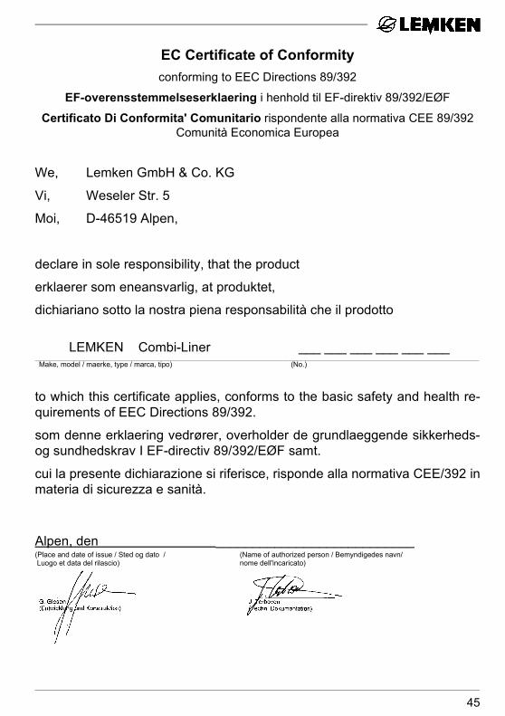
EC Certificate of Conformityconforming to EEC Directions 89/392
EF-overensstemmelseserklaering i henhold til EF-direktiv 89/392/EØF
Certificato Di Conformita' Comunitario rispondente alla normativa CEE 89/392 Comunità Economica Europea
We, Lemken GmbH & Co. KG
Vi, Weseler Str. 5
Moi, D-46519 Alpen,
declare in sole responsibility, that the product
erklaerer som eneansvarlig, at produktet,
dichiariano sotto la nostra piena responsabilità che il prodotto
LEMKEN Combi-Liner ___ ___ ___ ___ ___ _______________________________________________________________________________________________________________________________________________________________________________________________________________________________________________________________________________________________________________________________________________
Make, model / maerke, type / marca, tipo) (No.)
to which this certificate applies, conforms to the basic safety and health re-quirements of EEC Directions 89/392.
som denne erklaering vedrører, overholder de grundlaeggende sikkerheds-og sundhedskrav I EF-directiv 89/392/EØF samt.
cui la presente dichiarazione si riferisce, risponde alla normativa CEE/392 inmateria di sicurezza e sanità.
Alpen, den ___________________________(Place and date of issue / Sted og dato / (Name of authorized person / Bemyndigedes navn/ Luogo et data del rilascio) nome dell'incaricato)