Operable Unit 3-14 Tank Farm Soil and Groundwater Remedial ... · associated with the production of...
32
DOUID- 10676 Revision I June 2004 U.S. Department of Energy Idaho Operations Office Operable Unit 3-14 Tank Farm Soil and Groundwater Remedial In vestigation/ Feasibility Study Work Plan
Transcript of Operable Unit 3-14 Tank Farm Soil and Groundwater Remedial ... · associated with the production of...

DOUID- 10676 Revision I June 2004
U.S. Department of Energy Idaho Operations Office
Operable Unit 3-14 Tank Farm Soil and Groundwater Remedial In ves tiga tion/ Feasibility Study Work Plan

DOE/ID-10676 Revision 1
Project No. 23512
Operable Unit 3-14 Tank Farm Soil and G ro u n d w ate r Remed ia I I n ves t i gat io n/
Feasibility Study Work Plan
June 2004
Prepared for the U.S. Department of Energy
Idaho Operations Office

ABSTRACT
This revised Work Plan for Waste Area Group 3, Operable Unit 3-14 is the planning document for the remedial investigation, baseline risk assessment, and feasibility study that will lead to a final action for contaminated soil in the tank farm and Snake River Plain Aquifer within the Idaho Nuclear Technology and Engineering Center (INTEC) fence line. The U.S. Department of Energy Idaho Operations Office; the U.S. Environmental Protection Agency, Region 10; and the Idaho Department of Environmental Quality created Operable Unit 3- 14 because of uncertainties in the Operable Unit 3-13 comprehensive remedial investigation and feasibility study for INTEC. These unresolved issues led to selection of an interim action for the tank farm soil and the aquifer at INTEC under the Comprehensive Environmental Response, Compensation and Liability Act. The decision on a final remedy for these sites was deferred to Operable Unit 3-14. The former INTEC injection well and three No Action sites have been included in an Explanation of Significant Differences to the Operable Unit 3-13 Record of Decision, so these sites have been removed from this revision of the Work Plan. This revised Work Plan supersedes the previous Operable Unit 3-14 Work Plan and scope of work. As a result of an Agreement to Resolve Dispute, the Department of Energy committed to revising the data quality objectives for Operable Unit 3-14 as a modification to the Work Plan, and the revised objectives are presented in this Work Plan.
The revised Work Plan describes historical site information, the data collection tasks, and the proposed methodology for data use and interpretation associated with the production of a remedial investigation and feasibility report that supports selection of remedial alternatives for contamination in tank farm soil and the Snake River Plain Aquifer. Site data will be collected to support the selection of the final remedy for these sites using two investigation phases.
Phase 1 will involve evaluating extensive historical data on the tank farm and collecting gamma-radiation data from new and existing probeholes in tank farm soil. The scope of the Phase 2 activities will involve, at a minimum, more detailed characterization of radioactive areas within the tank farm soil. Treatability studies may be conducted using nonradioactive andor radioactive soil from the tank farm. The feasibility study will evaluate remedial alternatives to clean up the tank farm soil to mitigate risks and protect the Snake River Plain Aquifer. A strategy to accelerate a Record of Decision for tank farm soils and groundwater is presented.
iii


CONTENTS ... ABSTRACT ................................................................................................................................................ 111
ACRONYMS .............................................................................................................................................. xv
1 . INTRODUCTION ...........................................................................................................................
1.1
1.2
1.3
1.4
1.5
Comprehensive Environmental Response. Compensation and Liability Act Regulatory Background ......................................................................................................................... 1-2
1 . 1 . 1 Operable Unit 3- 13 ............................................................................................... . l -2 1.1.2 Operable Unit 3-13 Perched Water Final Action ................................................... 1-3 1.1.3 Operable Unit 3-13 Interim Action for the Snake River Plain Aquifer ................. 1-4 1.1.4 Operable Unit 3-13 Tank Farm Soils Interim Action ............................................ 1-4 1.1.5 Agreement to Resolve Dispute .............................................................................. 1-5
Regulatory Background of the Tanks ................................................................................. 1-6
Operable Unit 3-14 Objectives ........................................................................................... 1-8
Major Changes from the Previous Work Plan .................................................................. 1-10
OU 3-14 Scope .................................................................................................................. 1-10
1.5.1 Tank Farm Soil .................................................................................................... 1-10 1.5.2 Snake River Plain Aquifer ................................................................................... 1-11
2 . BACKGROUND AND OPERATIONAL HISTORY .................................................................... 2.3
Physical Setting ................................................................................................................... 2-3
2.1.2 INEEL Hydrogeology ............................................................................................ 2.6 2.1 . 1 INEEL Geology ..................................................................................................... 2.4
Tank Farm Historical Summary .......................................................................................... 2-9
2.2.1 Liquid Waste Calcination .................................................................................... 2-14 2.2.2
Current Mission of INTEC and the Tank Farm ................................................................ 2-16
2.3.1 Closure of the Tank Farm System ....................................................................... 2-16 2.3.2 Tank Farm Soil Remedial Investigation .............................................................. 2-18
Process Equipment Waste .................................................................................... 2-16
Physical Description of Tanks .......................................................................................... 2-18
300,OO 0-gal Tank Design ..................................................................................... 2-18
30,OO 0-gal Tanks ................................................................................................. 2-31 Tank Farm Piping and Secondary Containment .................................................. 2-33
2.4.1 2.4.2 2.4.3 2.4.4 2.4.5 Valve Boxes ......................................................................................................... 2-40
Past Tank Composition and Usage ...................................................................... 2-23
V

2.5 Sources of Tank Farm Waste ............................................................................................ 2-41
2.5.1 Fuel Reprocessing ................................................................................................ 2-41 2.5.2 Waste from Other Sources ................................................................................... 2-43
3 . EVALUATION OF OU 3- 14 CONTRIBUTING SOURCES ......................................................... 3. 1
3.1
3.2
3.3
3.4
3.5
OU 3-14 Soil Contamination Sites ..................................................................................... 3-1
3.1.1 Site CPP-3 1 ............................................................................................................ 3-3 3.1.2 Site CPP-28 .......................................................................................................... 3-22 3.1.3 Site CPP-79 .......................................................................................................... 3-31 3.1.4 Site CPP-15 .......................................................................................................... 3-41 3.1.5 Sites CPP-27 and CPP-33 .................................................................................... 3-47 3.1.6 Site CPP-26 .......................................................................................................... 3-59 3.1.7 Site CPP-32 .......................................................................................................... 3-64 3.1.8 Site CPP-16 .......................................................................................................... 3-69 3.1.9 Site CPP-20 .......................................................................................................... 3-72 3.1.10 Site CPP-25 .......................................................................................................... 3-77 3.1.1 1 Site CPP-58 .......................................................................................................... 3-78 3.1.12 Site CPP-24 .......................................................................................................... 3-84 3.1.13 Site CPP-30 .......................................................................................................... 3-84 3.1.14 Site CPP-96 .......................................................................................................... 3-84 3.1.15 Suspect Piping ..................................................................................................... 3-94 3.1.16 Summary of Operable Unit 3-14 Site Contamination .......................................... 3-95
Other Contributing Sources .............................................................................................. 3-99
3.2.1 Tank Residuals ..................................................................................................... 3-99 3.2.2 Sand Pad Contamination ...................................................................................... 3-99 3.2.3 Residual Contaminant Inventory in RCRA Piping ............................................ 3-1 00 3.2.4 Other INTEC Facilities ...................................................................................... 3-100 3.2.5 OU 3-13 Sources ................................................................................................ 3-100
OU 3- 13 Risk Assessment Summary .............................................................................. 3-1 00
3.3.1 3.3.2
Summary of the OU 3- 13 Tank Farm Surface Soil Pathway ............................. 3- 10 1 Summary of the OU 3-13 Groundwater Pathway Modeling and Risk Assessment ................................................................................................ 3-103
Contaminant Data Review Summary .............................................................................. 3.107
3.4.1 3.4.2 3.4.3
OU 3-13 Risk Assessment Uncertainties ........................................................... 3-107 Tank Farm Soil Contaminants of Potential Concern ......................................... 3-109 OU 3-14 BRA COPC Screening ........................................................................ 3-1 12
Conceptual Site Model for Risk Assessment .................................................................. 3-1 14
3.5.1 3.5.2 3.5.3
Contaminant Sources and Pathways .................................................................. 3-1 14
Groundwater Exposure Routes and Receptors .................................................. 3-1 16 Surface Soil Exposure Routes and Receptors .................................................... 3-1 16
vi

4 . CONTAMINANT FATE AND TRANSPORT MODELING ......................................................... 4. I
4.1 OU 3-14 Conceptual Model ................................................................................................ 4-1
4.1.1 Physical Setting ..................................................................................................... 4-1 4.1.2
4.1.4 4.1.5
Subsurface Geology of INTEC .............................................................................. 4-2 4.1.3 Hydrogeological Setting ........................................................................................ 4-3
Liquid Waste/Soil Interactions ............................................................................ 4-13 Perched Water and Contaminant Movement through the Vadose Zone in the Tank Farm Area ................................................................................................... 4-15
Subsurface/Groundwater Transport Modeling ................................................................. 4-19 4.2
4.3 Modeling of Other Sources ............................................................................................... 4-22
WORK PLAN RATIONALE .......................................................................................................... 5-1 5 .
5 . I
5.2
5.3
5.4
OU 3-1 3 and OU 3-14 Remedial Investigatiofleasibility Study Assumptions ................ 5-1
5.1.1 Baseline Risk Assessment Assumptions ................................................................ 5-2 5.1.2 Assumptions Used to Scope the Feasibility Study Remedy Evaluation ................ 5-3 5.1.3 Long-Term Land Use Assumptions ....................................................................... 5-4 5.1.4 Assumptions for Development of Preliminary Remedial Action Objectives ........ 5-6 5.1.5 Investigation-Derived Waste Management ............................................................ 5-6 5.1.6 HWMA/RCRA Tank Farm Closure/CERCLA Transition .................................... 5-7 5.1.7 Operational Interfaces ............................................................................................ 5-7
OU 3-14 Data Quality Objectives ....................................................................................... 5-8
5.2.1 Problem Statement ................................................................................................. 5-9 5.2.2 Decision Statements ............................................................................................. 5-13 5.2.3 Identify Decision Inputs ....................................................................................... 5-17 5.2.4 Define Study Boundaries ..................................................................................... 5-25 5.2.5 Define Decision Rules ......................................................................................... 5-28 5.2.6 Specify Tolerable Limits on Decision Errors ...................................................... 5-31 5.2.7 Optimize the Design ............................................................................................ 5-32
Phase 1 Investigation ........................................................................................................ 5-35
5.3.1 5.3.2 5.3.3 5.3.4
Installing and Gamma Logging Boreholes .......................................................... 5-36 Soil Moisture Monitoring .................................................................................... 5-37
Completion of Historical Data Review and Source Term Development ............. 5-37 Contaminant Transport Studies ........................................................................... 5-37
Phase 2 Field Investigation ............................................................................................... 5-38
5.4.1 5.4.2 5.4.3
Collecting Samples to Determine Composition ................................................... 5-38
Collecting Samples for Kd Studies ....................................................................... 5-39 Collecting Samples for Treatability Studies ........................................................ 5-39
vii

6 . REMEDIAL INVESTIGATION/FEASIBILITY STUDY TASKS ................................................ 6- 1
6.1
6.2
6.3
6.4
6.5
6.6
6.7
6.8
6.9
Project Plan and Scope ....................................................................................................... 6-1
6.1.1 Field Sampling Plans and Quality Assurance Project Plan ................................... 6-1 6.1.2 Health and Safety Plan ........................................................................................... 6-2 6.1.3 Waste Management Plan ....................................................................................... 6-2 6.1.4 Data Management Plan .......................................................................................... 6-2
Quality Assurance and Quality Control .............................................................................. 6-2
Data Management and Evaluation ...................................................................................... 6-3
6.3.1 Laboratory Analytical Data ................................................................................... 6-3 6.3.2 Field Data ............................................................................................................... 6-3 6.3.3 Data Evaluation ..................................................................................................... 6-4
Risk Evaluation and Methodology ..................................................................................... 6-4
Additional OU 3-14 Investigations ..................................................................................... 6-6
6.5.1 Contaminant Transport Study ................................................................................ 6-6 6.5.2 Treatability Study ................................................................................................ 6-11
Remedial Alternatives Development and Screening ........................................................ 6-14
6.6.1 Establish Remedial Action Objectives and General Response Actions .............. 6-14 6.6.2 Preliminary Remedial Process Options ............................................................... 6-15 6.6.3 Screening of Process Options .............................................................................. 6-16 6.6.4 Development of Alternatives ............................................................................... 6-16 6.6.5 Screening of Alternatives ..................................................................................... 6-16
Detailed Analysis of Alternatives ..................................................................................... 6-17
6.7.1 Overall Protection of Human Health and the Environment ................................. 6-18 6.7.2 Compliance with A R A R s .................................................................................... 6-18 6.7.3 6.7.4 6.7.5 Short-Term Effectiveness .................................................................................... 6-19 6.7.6 Implementability .................................................................................................. 6-19
6.7.8 State of Idaho Acceptance ................................................................................... 6-19 6.7.9 Community Acceptance ....................................................................................... 6-19
Long-Term Effectiveness and Permanence ......................................................... 6-18 Reduction of Toxicity, Mobility, and Volume ..................................................... 6-18
6.7.7 Costs .................................................................................................................... 6-19
Remedial InvestigatiodFeasibility Study Report ............................................................. 6-19
Proposed Plan and Record of Decision ............................................................................. 6-20
viii

6.10 Identification of Potentially Applicable or Relevant and Appropriate Requirements (ARARs) ........................................................................................................................... 6.20
6.10.1 6.10.2 To-Be-Considered Guidance ............................................................................... 6-24
Preliminary A R A R s Identification for OU 3-14 Tank Farm Soils ...................... 6-21
7 . SCHEDULE ..................................................................................................................................... 7-1
7.1 OU 3-14 RYFS Activities ................................................................................................... 7-1
7.2 Accelerated OU 3- 14 Schedule ........................................................................................... 7-6
8 . PROJECT MANAGEMENT PLAN ............................................................................................... 8. 1
8.1 Key Positions and Responsibilities ..................................................................................... 8-1
8.1.1 8.1.2 INTEC Clean/Close Director ................................................................................. 8-2 8.1.3 SP-6 Manager ........................................................................................................ 8-2 8.1.4 8.1.5 OU 3-14 RI/FS Task Lead ..................................................................................... 8-4
DOE Idaho OU 3-14 Remediation Project Manager ............................................. 8-2
SP-6 Project Engineer ............................................................................................ 8-3
8.2 Planning .............................................................................................................................. 8-4
8.2.1 8.2.2 Project Baselines .................................................................................................... 8-4
Planning and Budgeting Overview ........................................................................ 8-4
8.3 Change Control ................................................................................................................... 8-5
8.4 Communications ................................................................................................................. 8.5
8.4.1 Routine Reports ..................................................................................................... 8-5 8.4.2 Event Reports ......................................................................................................... 8-5
9 . REFERENCES ................................................................................................................................ 9-1
Appendix A-Tank Farm Soil and Groundwater Field Sampling Plan for the Operable Unit 3-14 Remedial Investigation/ Feasibility Study ...................................................... A-1
Appendix B-Tank Farm Soil and Groundwater Health and Safety Plan for the Operable Unit 3-14 Remedial Investigation/ Feasibility Study ...................................................................... B- 1
Appendix C-Waste Management Plan for the Operable Unit 3-14 Tank Farm Soil and Groundwater Remedial InvestigatiodFeasibility Study ................................................................. C-1
Appendix D-Release Site Field Investigation Summaries ...................................................................... D. 1
Appendix E-Evaluation of the Feasibility of an Early Decision and Permanent Remedy for Tank Farm Soil ............................................................................................................................... E-1
ix

1.1 .
1.2 .
Location of the INEEL, INTEC. and the tank farm soil sites ........................................................ 1-3
Map of OU 3.14. including the tank farm area. contaminated soil sites. and key structures ........ 1-7
2- 1 . Aerial view of the INEEL. showing the bordering mountain ranges ............................................. 2-2
2.2 . Typical vertical cross-section structure of a basalt flow in the ESRP ........................................... 2-5
2.3 . Conceptual view of the tank farm looking northeast ..................................................................... 2-8
2.4 . Surface membrane liner ................................................................................................................. 2-9
2.5 .
2.6 .
2.7 .
Schematic showing the PEW system looking east. including the main transfer lines ................. 2-10
Upgrade of piping north of CPP-604 ........................................................................................... 2-11
March 2004 tank farm waste tank volumes ................................................................................. 2-13
2.8 . Monolithic octagonal vault for WM-180 ..................................................................................... 2-17
2.9 . Pillar and panel octagonal vault for WM-182 .............................................................................. 2-18
2- 10 . Vault and dome of WM.185, with the concrete beams and concrete risers on top ..................... 2-19
2- 1 1 . Monolithic square vault for WM- 190 (forefront) and WM-189 .................................................. 2-20
2- 12 . Schematic of tank vault sumps for WM- 180 and WM- 18 1 ......................................................... 2-22
2.13 . Schematic of tank vault sumps for tanks WM-182 through WM-186 ......................................... 2-23
2.14 . Schematic of tank vault sumps for tanks WM-187 through WM-190 ......................................... 2-24
2.15 . Schematic of tank vault sump lines to the centralized tank farm PEW line ................................ 2-25
2.16 . Schematic of tank vault with sand pad to cushion the tank bottom. for tanks WM-182 through WM- 190 ......................................................................................................................... 2-26
2.17 . Design of encasement with split clay tile .................................................................................... 2-32
2.18 . Locations of the waste transfer lines using split clay pipe and split steel encasement ................ 2-33
2- 19 . Split steel encasement design ...................................................................................................... 2-35
2.20 . Stainless-steel-lined concrete trough encasement design ............................................................ 2-36
2.21 . Piling and support cap design for the stainless-steel-lined concrete trough encasement design ....................................................................................................................... 2-36
2.22 . Stainless-steel pipe-within-a-pipe encasement design ................................................................. 2-37
X

2.23 . The process flow of historical fuel operations at INTEC ............................................................ 2-42
2.24 . Facilities that were sources of liquid waste stored at the tank farm ............................................ 2-43
3.1 .
3.2 .
Known tank farm soil contamination sites ..................................................................................... 3-2
Locations of the A-40 and A-50 series wells installed in 1973 and 1975. respectively ................ 3-9
3.3 . CPP-3 1 release site boundary and locations of monitoring wells and soil probes in and around the release site .................................................................................................................. 3-10
3.4 . Plan view of the piping configuration at the CPP-31 release site ................................................ 3-11
3.5 . Extent of lateral contamination at the CPP-3 1 release site .......................................................... 3-15
3.6 . Fence diagram showing vertical and lateral extent of soil contamination (measurements in R/hr) at CPP-3 1 ............................................................................................................................ 3-16
3.7 . East.to.west, A.to.A’, fence diagram through the CPP-3 1 zone of contamination ..................... 3-17
3.8 . West.to.east, B.to.B’, fence diagram through the CPP-3 1 zone of contamination ..................... 3-18
3.9 . North.to.south, C.to.C’, fence diagram through the body of contaminated soil at CPP- 31 ....... 3-19
3.10 . North.to.south, D.to.D’. fence diagram through the body of contaminated soil at CPP-31 ....... 3-20
3-1 1 . North.to.south, E.to.E’, fence diagram through the body of contaminated soil at CPP-31 ........ 3-21
3- 12 . CPP-28 trenching investigation location map .............................................................................. 3-23
3- 13 . Test pipes being driven into the ground during the contaminant release investigation in 1974 at CPP.28 ............................................................................................................................ 3-25
3.14 . Drill hole found in waste-transfer line 3”PWA-1005 at CPP-28 ................................................. 3-27
3.15 . CPP-28 fence diagram location map ............................................................................................ 3-28
3.16 .
3.17 . North-south fence diagram through the contaminated soil zone at CPP-28 ................................ 3-30
3-1 8 .
East-west fence diagram through the contaminated soil zone at CPP-28 .................................... 3-29
CPP-79-Shallow piping configuration ......................................................................................... 3-32
3.19 . West-to-east fence diagram through A.61, CPP.79.1, and A-62 showing soil sample analytical results .......................................................................................................................... 3-35
3.20 . Map of the tank farm showing locations of boreholes drilled near CPP-79 ................................ 3-37
3-2 1 . Cross section through CPP-79 release site showing planned excavation depths ......................... 3-38
3.22 . Site CPP-15 location map ............................................................................................................ 3-42
xi

3.23 . Cross section showing the general shape of the 1983 excavation to remove solvent tank .......... 3-43
3.24 . CPP-15 sample location map for soil samples collected in 1995 ................................................ 3-44
3.25 . CPP-27/33 release sites showing location of 12.in . pressure relief line and associated piping, extents of excavation. and borehole/well locations ......................................................... 3-48
3.26 . Schematic diagram showing piping layout in release area CPP-27/33 ........................................ 3-49
3.27 . Photo showing the amount of soil removed from the CPP-27/33 release area during 1983 excavation .................................................................................................................................... 3-51
3.28 . Photo showing the amount of soil removed from the CPP-27/33 release area during 1983 excavation .................................................................................................................................... 3-52
3.29 . Extent of 1983 excavation within the CPP-27/33 release sites .................................................... 3-53
3.30 . Map of site CPP-27 showing the locations of previously drilled boreholes ................................ 3-54
3-3 1 . Isometric view of piping associated with the CPP-26 steam release ........................................... 3-60
3.32 . Location of the existing boreholes at site CPP-26 ....................................................................... 3-62
3.33 . Location of the excavated area within site CPP-26 ..................................................................... 3-63
3.34 . CPP-32 east and west release sites ............................................................................................... 3-66
3.35 . Site CPP-16 location map ............................................................................................................ 3-70
3.36 . Excavation in 1982 north of building CPP-604 looking west showing the soil that was removed ................................................................................................................................ 3-73
3.37 . Closeup view of 1982 excavation north of building CPP-604 showing the soil that was removed ................................................................................................................................ 3-74
3.38 . Northeastern view of 1982 excavation north of building CPP-604 showing extent of excavation through the CPP-20 and CPP-25 release sites ........................................................... 3-75
3.39 . Eastern view of 1982 excavation north of building CPP-604 showing extent of excavation through the CPP-20 and CPP-25 release sites ............................................................................. 3-76
3.40 . Map showing location of release site CPP.58, piping. and leak locations .................................. 3-79
3.41 . Tank farm map showing surface gamma survey results .............................................................. 3-85
3.42 . Tank farm map showing wells. cathodic-protection boreholes/anode estimated locations. and probe/soil-boring locations .................................................................................................... 3-87
3.43 . Potentially abandoned shoring devices remaining from upgrades to the tank farm .................... 3-92
3.44 . Decision logic for tank farm soil COPC identification .............................................................. 3-1 10
xii

3.45 .
3.46 .
4.1 .
4.2 .
4.3 .
4.4 .
4.5 .
4.6 .
4.7 .
4.8 .
4.9 .
5.1 .
7.1 .
7.2 .
8.1 .
Conceptual site model for OU 3-14 ........................................................................................... 3-1 1 1
INTEC conceptual model features ............................................................................................. 3-1 15
INTEC well location map .............................................................................................................. 4-4
Approximate past extent of shallow perched water identified in the WAG 3 RYFS ..................... 4-5
North-south fence diagram of INTEC ........................................................................................... 4-6
Contour map of the top surface of the upper basalt flow ............................................................... 4-8
Fence diagram location map .......................................................................................................... 4-9
East-west fence diagram of INTEC ............................................................................................. 4-10
Southwest-to-northeast fence diagram through the tank farm area ............................................. 4-11
Conceptual model of pathways of water and contaminant migration at the alluviumhasalt interface ....................................................................................................................................... 4-17
Modeling approach to support OU 3-14 RI/FS/BRA and other INTEC sources ......................... 4-21
Decision logic for investigating known soil release sites ............................................................ 5-34
Schedule of major project and critical path activities for the OU 3-14 ......................................... 7-2
OU 3-14 RYFS Work Plan logic .................................................................................................... 7-5
OU 3-14 tank farm RYFS organizational structure ........................................................................ 8-2
xiii
TABLES
2- 1 . Estimated chemical properties and concentrations in 300.00 0.gal tanks .................................... 2-27
2.2 . Estimated radionuclide concentrations (Ci/L) in 300,00 0.gal tanks ............................................ 2-28
2.3 . Types of fuel dissolution performed at INTEC ........................................................................... 2-30
3.1 . Known release sites contained in CPP-96 ..................................................................................... 3-4
3.2 . Direct radiation measurements in 1975 from boreholes or observation wells installed at Site CPP-31 after the release ....................................................................................................... 3-13
3.3 . Summary of the subsurface radiation profile performed on selected probes at site CPP-3 1 on August 18. 1992 ...................................................................................................................... 3-22
3.4 . 1974 test hole radiation readings for CPP-28 (R/hr) ................................................................... 3-26
3.5 . Borehole sample result comparison table .................................................................................... 3-36
3.6 . Analytical results for soil samples collected during the 1995 construction activities at CPP- 15 ......................................................................................................................................... 3-45
3.7 . Radionuclide sample analytical results for borehole CPP-33-1 ................................................... 3-55
3.8 . Analytical results for the soil samples collected at CPP-27- 1. 27.2. and 27-3 ............................ 3-57
3.9 . Analytical results for the soil samples collected at CPP-26 ......................................................... 3-65
3.10 . Analytical results for soil samples collected at site CPP-32E ..................................................... 3-67
3-1 1 . Gamma scan results for a soil sample collected from the CPP-16 release site ............................ 3-72
3- 12 . Analytical results summary table for contaminated soil excavated during HLWTFU project .......................................................................................................................................... 3-77
3.13 . Summary of excavation activity details for the individual tank farm release sites ...................... 3-88
3.14 . Comparison of the bounding estimate of contaminated backfill volume and tank farm volume ......................................................................................................................................... 3-94
3.15 . Estimated curies remaining at CPP-96 release sites .................................................................... 3-96
3.16 . OU 3-13 human health baseline risk assessment summary for tank farm soils and groundwater ............................................................................................................................... 3- 10 1
3.17 . Summary of OU 3-13 tank farm surface soil release sites, OU 3-13 COCs. and PRGs ............ 3-102
3-1 8 . Summary of the identified groundwater COPCs for OU 3-13 ................................................... 3-104
3- 19 . Summary of the OU 3- 13 maximum and peak simulated contaminant concentrations for the entire aquifer domain ........................................................................................................... 3-105
xiv

3.20 .
3.21 .
5.1 .
5.2 .
5.3 .
5.4 .
5.5 .
5.6 .
6.1 .
6.2 .
7.1 .
OU 3- 13 groundwater ingestion cancer risk and noncancer hazard quotients in the year 2095 and for the peak concentration if it occurs beyond the year 2095 ............................. 3-106
Preliminary summary of COPCs and analytical methods required to meet data needs for OU 3-14 tank farm soil release sites .......................................................................................... 3-1 13
Summary of DQO Steps 1 through 7 outputs .............................................................................. 5-10
Summary of DQO Step 2 information ......................................................................................... 5-14
Summary of decision inputs required to resolve the PSQs .......................................................... 5-17
Spatial scale of decision-making ................................................................................................. 5-26
Summary of parameters of interest. action levels. and decision rules ......................................... 5-29
Historical data review and source term development tasks to be completed during the Phase 1 remedial investigation .................................................................................................... 5-38
Preliminary list of U s for tank farm soil and groundwater .................................................. 6-22
Preliminary list of TBC environmental criteria for OU 3-14 ....................................................... 6-23
Schedule for the major OU 3-14 RWS documents ....................................................................... 7-6
xv

xvi

A P S
ARAR
ARD
bgs
BRA
CERCLA
COC
COPC
CPP
CSM
CSSF
CTS
DD&D
DOE
DOE Idaho
DQOs
EPA
ESD
ESRF'
FAST
FFNCO
FDP
FS
FSP
FY
ACRONYMS
Atmospheric Protection System
applicable or relevant and appropriate requirement
agreement to resolve dispute
below ground surface
baseline risk assessment
Comprehensive Environmental Response, Compensation and Liability Act
contaminant of concern
contaminant of potential concern
Chemical Processing Plant
conceptual site model
Calcined Solids Storage Facility
contaminant transport study
deactivation, decontamination, and decommissioning
Department of Energy
Department of Energy Idaho Operations Office
data quality objectives
U.S. Environmental Protection Agency
explanation of significant differences
Eastern Snake River Plain
Fluorinel Dissolution Process and Fuel Storage (facility CPP-666)
Federal Facility Agreement and Consent Order
fluorine1 dissolution process
feasibility study
field sampling plan
fiscal year
xvii
GRA
HASP
HI
HLW
HLW&FD FEIS
HLWTFU
HWMA
ICDF
ICP
ICPP
ICRP-2
IDEQ
IDW
IEDMS
INEEL
INTEC
Kd
MCL
MCP
MRDS
NCP
NEPA
NGLW
NOV
NPAT
NPL
general response action
health and safety plan
hazard index
high-level waste
Idaho High-Level Waste and Facilities Disposition Final Environmental Impact Statement
High Level Waste Tank Farm Upgrade
Hazardous Waste Management Act
INEEL CERCLA Disposal Facility
Idaho Completion Project
Idaho Chemical Processing Plant
International Commission on Radiological Protection-2
Idaho Department of Environmental Quality
investigation-derived waste
Integrated Environmental Data Management System
Idaho National Engineering and Environmental Laboratory
Idaho Nuclear Technology and Engineering Center
soil/water partition coefficient
maximum contaminant level
management control procedure
monitoring report/decision summary
National Oil and Hazardous Substances Pollution Contingency Plan
National Environmental Policy Act
newly generated liquid waste
notice of violation
neutron probe access tube
National Priorities List
xviii

NRTS
NWCF
ou PCB
PEW
PRG
PSQ
QAPP
RAL
RAO
RBC
RCRA
RfD
RI
RVBRA
RVFS
ROD
RWMC
SAP
SBW
SF
SNF
SP
SRPA
svoc TBC
National Reactor Testing Station
New Waste Calcine Facility (CPP-659)
operable unit
polychlorinated biphenyl
process equipment waste
preliminary remediation goal
principal study question
quality assurance project plan
Radiological Analysis Laboratory
remedial action objective
risk-based concentration
Resource Conservation and Recovery Act
reference dose
remedial investigation
remedial investigationhaselhe risk assessment
remedial investigatiodfeasibility study
Record of Decision
Radioactive Waste Management Complex
Sampling and Analysis Plan
sodium-bearing waste
slope factor
spent nuclear fuel
subproject
Snake River Plain Aquifer
semivolatile organic compound
to be considered
xix

TBP
TFIA
TLD
TRU
UCL
USGS
USSR
voc WAG
WCF
tributyl phosphate
Tank Farm Interim Action
thermoluminescent dosimetry
transuranic
upper confidence level
United States Geological Survey
Union of Soviet Socialist Republics
volatile organic compound
waste area group
Waste Calcining Facility
xx

Operable Unit 3 4 4 Tank Farm Soil and Groundwater Remedial I nvestigat ion/Feasi bi lity Study Work Plan
1. INTRODUCTION
After World War 11, the United States became embroiled in the Cold War with the former Union of Soviet Socialist Republics (USSR). After the USSR detonated a nuclear device in 1949 and the Korean War began in 1950, the U.S. Atomic Energy Commission’s main priority became focused more on defense than on peaceful uses of the atom. During the 1950s, the United States began dissolving spent nuclear fuel (SNF) removed from reactors to recover the unused uranium-235 (U-235) for use in the development of nuclear submarines and in the nuclear weapons program. Powerful acids were used to dissolve both the metal cladding around the uranium fuel and the fuel itself. A chemical solvent that would form a compound only with the uranium was added to separate the uranium from the dissolved solution. The uranium was then extracted and refined.
In 195 1 , an SNF reprocessing plant called the Chemical Processing Plant (CPP) was built in Idaho on a government reservation known as the National Reactor Testing Station (NRTS). (Today, the CPP is known as the Idaho Nuclear Technology and Engineering Center [INTEC], and the NRTS is known as the Idaho National Engineering and Environmental Laboratory [INEEL] .) Although the CPP’ s primary missions were research and recycling nuclear fuel for the Navy, the U-235 reprocessed at the CPP was also used to produce radioactive lanthanum- 140, which was needed for experiments associated with development of thermonuclear weapons. The CPP reprocessed more than 100 types of fuel, each in a different campaign. The fuel came from Navy ships, reactors on the NRTS, commercial reactors, and university and test reactors located throughout the world (Stacy 2000).
The CPP was a heavy industrial plant that generated large amounts of radioactive waste. The Atomic Energy Commission’s general waste management philosophy during the Cold War was to retain the waste that had high levels of radioactivity and to dilute and disperse the waste that had low levels of radioactivity to the air, water, or soil. At the CPP, highly radioactive liquid wastes were stored in an underground tank farm, concentrated, and/or solidified, thus reducing the cost of managing the waste. The tanks were made of stainless steel to store and manage liquid waste from the CPP. The wastes were stored in acidic form, which largely prevented precipitation of solids and kept the fission products dissolved. This process is different from the approach used at the Hanford Site, where the wastes were neutralized and stored in carbon-steel tanks, which caused tank corrosion and the formation of sludge.
With the dissolution of the USSR, the Cold War came to an end, the U.S. government decided (in 1992) to discontinue reprocessing SNF at the CPP, and the priority shifted to cleanup of the legacy wastes from the Cold War. Subsequently, the facility was renamed INTEC to reflect its changed mission. Although the tank farm tanks at INTEC have not leaked, piping to the tanks has leaked and contaminated soil and potentially groundwater.
This Remedial InvestigationFeasibility Study (RI/FS) Work Plan lays out the strategy for investigating the extent of contamination from the tank farm, evaluating the resultant risks, and determining ways to clean it up and accelerate remedy selection. This Work Plan also includes the Field Sampling Plan (FSP, Appendix A); the Health and Safety Plan (HASP, Appendix B); the Waste Management Plan (Appendix C); summaries of release site field investigations (Appendix D); and an Evaluation of the Feasibility of an Early Decision and Permanent Remedy for Tank Farm Soil (Appendix E).
1-1

1 .I Comprehensive Environmental Response, Compensation and Liability Act Regulatory Background
On July 14, 1989, the INEEL was proposed for listing on the U.S. Environmental Protection Agency (EPA) National Priorities List (NPL) (54 FR 48 184) using Hazard Ranking System procedures found in the National Oil and Hazardous Substances Pollution Contingency Plan (NCP) (40 CFR 300). The INEEL was subsequently placed on the NPL and became subject to the provisions of the Comprehensive Environmental Response, Compensation and Liability Act (CERCLA) (42 USC 9 960 1 et seq.) on November 15, 1989. Contaminated sites at INTEC contributed to listing the INEEL on the NPL. The successor to the Atomic Energy Commission, the U.S. Department of Energy-Idaho Operations Office (DOE Idaho), EPA Region 10, and the Idaho Department of Environmental Quality (IDEQ) (i.e., collectively known as the Agencies) signed a Federal Facility Agreement and Consent Order (FFA/CO) and Action Plan (DOE-ID 1991) for CERCLA cleanups and Resource Conservation and Recovery Act (RCRA) corrective actions on the INEEL. The FFNCO divided the INEEL into 10 waste area groups (WAGS). INTEC was designated as WAG 3. WAG 3 was originally divided into 13 operable units (OUs). The locations of the INEEL, INTEC, WAG 3, and the tank farm soil sites are shown on Figure 1-1.
The goals of the FFNCO are to ensure that (1) potential or actual INEEL releases of contaminants to the environment are thoroughly investigated in accordance with the NCP and (2) appropriate response actions are taken to protect human health and the environment. The FFNCO established the procedural framework and schedule for developing, prioritizing, implementing, and monitoring response actions at the INEEL in accordance with CERCLA and RCRA (42 USC 8 9601 et seq.) legislation and the Idaho Hazardous Waste Management Act (HWMA) (IC 8 39-4401).
The Secretary of Energy’s policy statement (DOE 1994) on the National Environmental Policy Act (NEPA) (42 USC 8 4321 et seq.) stipulates that the U.S. Department of Energy (DOE) will rely on the CERCLA process for review of actions to be taken under CERCLA and to address the environmental aspects of CERCLA projects. The policy statement also requires that DOE address NEPA aspects and public involvement procedures by incorporating NEPA requirements, to the extent practical, in documents and public involvement activities generated under CERCLA.
1.1.1 Operable Unit 3-1 3
The FFNCO designated the comprehensive RYFS for INTEC (WAG 3) as OU 3-13. All known release sites within INTEC in 1997 were evaluated in the OU 3-13 comprehensive R W S (DOE-ID 1997a, 1997b). Ninety-five release sites were evaluated in the remedial investigation (DOE-ID I997a), 40 of which exceeded the soil remedial action objectives (RAOs) and were further evaluated for remedial alternatives in the feasibility study (FS) (DOE-ID 1997b). However, data gaps and uncertainties associated with contaminant source estimates, the extent of contamination, potential releases from the tank farm soil, and site risk prevented the Agencies from reaching a final remedial decision on the former INTEC injection well, groundwater inside the INTEC security fence, and the tank farm soils. As a result, the Agencies created OU 3-14 to address the final action, while interim actions are being implemented for tank farm soil and groundwater under the OU 3-13 Record of Decision (ROD), which was signed in October 1999 (DOE-ID 1999a). The interim actions are designed to control the principal threat wastes at the tank farm site, control exposure to contaminants in tank farm soil, and minimize moisture that may infiltrate through tank farm soil and transport contaminants to the Snake River Plan Aquifer (SRPA). The interim actions will be in place until the final remedy for these sites is selected and implemented as part of the OU 3-14 R W S process.
1-2

I Idaho Nuclear Technology and Engineering Center,
WAG 3
03 GA51006 01 Soil Site CPP-96
Figure 1-1. Location of the INEEL, INTEC, and the tank farm soil sites.
1.1.2 Operable Unit 3-13 Perched Water Final Action
Perched water has been observed beneath the tank farm and is a pathway for contaminants to migrate to the SRPA (DOE-ID 1999a). The OU 3-13 perched water (Group 4) remediation goals are to ( 1 ) reduce recharge to the perched zones and (2) minimize the migration of contaminants to the SRPA so that SRPA groundwater outside of the current INTEC security fence meets applicable State of Idaho groundwater standards by 2095. The selected OU 3- I3 perched water remedy is institutional controls with aquifer recharge controls and includes the following items:
Implementing institutional controls that include limiting access to prevent perched water use and to prevent future unauthorized drilling into or through the perched zone.
1-3

0 Controlling surface water recharge to perched water. The former INTEC percolation ponds were removed from service and replaced with percolation ponds outside the INTEC perched water area on August 26, 2002. Additional infiltration controls may include minimizing lawn irrigation at INTEC and, if necessary, lining the adjacent reach of the Big Lost River. Controls may also include closing and relocating the existing sewage treatment plant lagoons and infiltration galleries, upgrading INTEC drainage controls, repairing leaking fire water lines, and eliminating steam condensate discharges (DOE-ID 1999a).
Measuring moisture content and contaminant of concern (COC) concentrations in the perched water to determine if water contents and contaminant fluxes are decreasing as predicted and to verify the OU 3-1 3 vadose zone model.
1.1.3 Operable Unit 3-13 Interim Action for the Snake River Plain Aquifer
The human health threat posed by the contaminated SRPA is exposure to radionuclides via ingestion by a hypothetical future resident. The Agencies selected an interim action for the SRPA. While the remedy selection for contaminated SRPA groundwater outside the INTEC security fence is final, the final remedy for the contaminated portion of the SRPA inside the fence was deferred to OU 3-14. As a result of dividing the SRPA groundwater contaminant plume associated with INTEC operations into two zones, the remedial action is classified as an interim action (DOE-ID 1999a). The OU 3-13 remediation goals for the SRPA outside of the current INTEC security fence are to (1) prevent current on-Site workers and nonworkers from ingesting contaminated drinking water above the applicable State of Idaho groundwater standards or risk-based groundwater concentration during the institutional control period and (2) achieve the applicable State of Idaho groundwater standards or risk-based groundwater concentrations in the SRPA plume south of the INTEC security fence by the year 2095. The selected OU 3-13 SRPA interim action, for contaminated portions of the SRPA both inside and outside the INTEC security fence, is institutional controls with monitoring and contingent remediation. This interim action consists of three components:
Existing and additional institutional controls over the area of the SRPA that exceeds the maximum contaminant levels (MCLs) for H-3,I-129, and Sr-90 to prevent current and future groundwater use until drinking water standards are met.
0 Groundwater monitoring to determine if specific SRPA groundwater contaminant concentrations exceed their action levels. If action levels are exceeded, determine if the impacted portion of the SRPA is capable of producing more than 0.5 gpm, which is considered the minimum drinking water yield necessary for the aquifer to serve as a drinking water supply. If both of these conditions are met, conduct treatability studies.
0 Implementing contingent pump and treat remediation if treatability studies indicate sufficient quantities of COCs and contaminated groundwater can be extracted selectively and treated cost-effectively to meet the MCLs outside the INTEC security fence by 2095 (DOE-ID 1999a).
1.1.4 Operable Unit 3-13 Tank Farm Soils Interim Action
The principal threats posed by tank farm soils are direct radiation exposure to workers or the public and the potential leaching and transport of contaminants to perched water or the SRPA. The following items are remediation goals for the Tank Farm (soils) Interim Action (TFIA, Group 1) (DOE-ID 1999a):
0 Restrict access to soils to control exposure to workers and prevent exposure to the public
1 -4

Reduce precipitation infiltration by 80% of the average annual precipitation at the site by grading and surface-sealing the tank farm soils
Prevent surface water run-on from a one-in-25-year, 24-hour storm event
Improve exterior building drainage to direct water away from the contaminated areas.
The interim action specified for tank farm soil consists of institutional controls with surface water control to reduce surface water infiltration into tank farm soil until OU 3-14 remedial action begins.
1.1.5 Agreement to Resolve Dispute
On December 4,2002, the EPA issued a Notice of Violation (NOV) for a dispute raised under the FFNCO for WAG 3 (EPA 2002a). The NOV alleged that violations were caused by the failure of DOE Idaho to complete work as required under the Remedial DesigdRemedial Action Work Plan for Group I , Tank Farm Interim Action (DOE-ID 2000a). On February 21,2003, the Agencies agreed to resolve the dispute.
In the Agreement to Resolve Dispute (ARD) (DOE 2003), DOE Idaho agreed to meet the intent of the Tank Farm Interim Action by completing two phases. Phase 1 of the interim action was completed before September 30,2003, and included the following:
Grading and lining with concrete all existing storm water collection ditches around the tank farm and out to the discharge point.
Replacing existing culverts around the tank farm and out to the discharge point with larger culverts to accommodate the expected increase in storm water flow.
Constructing a lift station at the intersection of Beech Street and Olive Avenue to pump storm water to a location where the water will drain freely to the discharge point.
Constructing concrete headwalls and end walls as necessary throughout the lined drainage system.
Constructing a lined evaporation pond to collect storm water run-off from the tank farm and other INTEC areas. All drainage ditches within the scope of this project were routed to this basin.
Constructing two concrete-lined ditches within the tank farm to collect and direct precipitation run-off to the surrounding storm water collection system.
Constructing a new fence around the evaporation pond.
Phase 2 of the TFIA requires DOE Idaho to place an infiltration barrier (concrete, asphalt, high-density polyethylene, polyurea, or temporary enclosures that achieve the OU 3-1 3 G O s ) over the affected areas of the three principal soil contamination sites (CPP-28, -3 1, and -79) by September 30, 2004. The purpose of Phase 2 is to meet the intent of the interim action, which is to reduce precipitation infiltration.
In the ARD, DOE Idaho also agreed to revise the data quality objectives (DQOs) as a modification to the existing Operable Unit 3-14 Tank Farm Soil and Groundwater Phase 1 Remedial Znvestigation/Feasibility Study Work Plan (DOE-ID 2000b). This revised RI/FS Work Plan supersedes the December 2000 Work Plan and the 1999 Scope of Work document (DOE-ID 1999b). In the ARD, the
1-5

Agencies agreed to a planned date of December 31,2006, for completion of an early OU 3-14 ROD. An evaluation of the feasibility of accelerating the ROD for tank farm soils and expediting a phased implementation of the permanent remedy is presented in Appendix E. The Agencies agreed to refine the planned date for the OU 3-14 ROD after the revised DQOs are established (Section 3.3.1 of the ARD [DOE 20031).
DOE Idaho also agreed in the ARD to separate the non-tank farm soil components from the OU 3-14 RWS (the former INTEC injection well [CPP-231 and three No Action sites) and prepare a draft Explanation of Significant Differences (ESD) to the OU 3-13 ROD to address these components. The ESD, which was signed by the Agencies in January 2004 (DOE-ID 2004a), transferred the injection well and three No Action sites back to OU 3-13.
The ARD also states, “The Agencies agree to work collaboratively to expedite a phased implementation of the tank farm soil permanent remedy. The sequencing of tank closures and the schedule for tank farm soil remediation will be integrated to occur in stages” (DOE 2003). Information from RCRA tank closures, INTEC waste operations, and deactivation, decontamination, and decommissioning (DD&D) of tank farm infrastructure are included in this revised R W S Work Plan in order to integrate the OU 3-14 remedy selection and implementation with these other tank farm activities.
1.2 Regulatory Background of the Tanks
The hazardous components stored at the tank farm are regulated through the IDEQ. The tank farm is currently operating under RCRA/HWMA (IC 0 39-4401 et seq.) interim status (LMITCO 1999a) as a hazardous waste management unit and is undergoing closure. As such, the requirements of 40 CFR 265, “Interim Status Standards for Owners and Operators of Hazardous Waste Treatment, Storage, and Disposal Facilities,” apply to tank closure. These regulations apply to 11 underground tanks with a capacity of approximately 300,000 gal each, four tanks with a capacity of approximately 30,000 gal each, the tank contents, and ancillary equipment and piping.
Under the terms of a Consent Order to the Notice of Noncompliance with the State of Idaho and EPA (DOE-ID 1992), DOE Idaho was required to permanently cease use of the tanks or bring the tanks into compliance with secondary containment requirements. The DOE Idaho decided to close the eleven 300,000-gal and four 30,000-gal underground tanks within the tank farm in part due to the impracticality of lifting the large tanks to install a liner underneath them. The second modification to the Consent Order (DOE 1998a) required DOE to cease use of the tanks in the pillar and panel vaults (tanks WM-182, -183, -184, -185, and -186 as shown on Figure 1-2) by June 30, 2003, and the remaining tanks by December 3 1,2012. Ceasing use of the tanks, as defined in the Consent Order, meant that DOE would empty the tanks down to their heels (Le., the liquid level remaining in each tank was lowered to the greatest extent possible by the use of existing transfer equipment [DOE-ID 1998a1).
Closure of the tanks will occur in phases, according to the Idaho Hazardous Waste Management Act/Resource Conservation and Recovery Act Closure Plan for Idaho Nuclear Technology and Engineering Center Tanks WM-182 and WM-183 (DOE-ID 2001a). DOE Idaho anticipates that the tank farm will continue to operate until 2012, while various parts of the facility are being closed. Final closure of any component of the tank farm will not be complete until all of the tanks have been closed. The final closure plan will address closure and any required post-closure care of the tank farm. A decision to close the unit as a landfill or as a RCRA/HWMA clean closure will be determined during final closure (DOE-ID 2001 b), currently scheduled for December 3 1, 201 2.
1-6

. .
* . ' . ,
w
"rl E W f \
Y
P s
' t"! B L
II
d ry 0 \\ /--
I - ' /ill i I It- I I //
.;i 3
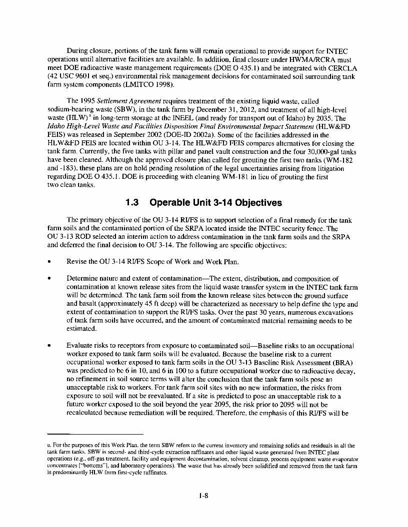
During closure, portions of the tank farm will remain operational to provide support for INTEC operations until alternative facilities are available. In addition, final closure under HWMARCRA must meet DOE radioactive waste management requirements (DOE 0 435.1) and be integrated with CERCLA (42 USC 9601 et seq.) environmental risk management decisions for contaminated soil surrounding tank farm system components (LMITCO 1998).
The 1995 Settlement Agreement requires treatment of the existing liquid waste, called sodium-bearing waste (SBW), in the tank farm by December 31, 2012, and treatment of all high-level waste (HLW) a in long-term storage at the INEEL (and ready for transport out of Idaho) by 2035. The Idaho High-Level Waste and Facilities Disposition Final Environmental Impact Statement (HLW&FD FEIS) was released in September 2002 (DOE-ID 2002a). Some of the facilities addressed in the HLW&FD FEIS are located within OU 3-14. The HLW&FD FEIS compares alternatives for closing the tank farm. Currently, the five tanks with pillar and panel vault construction and the four 30,000-gal tanks have been cleaned. Although the approved closure plan called for grouting the first two tanks (WM-182 and -183), these plans are on hold pending resolution of the legal uncertainties arising from litigation regarding DOE 0 435.1. DOE is proceeding with cleaning WM-181 in lieu of grouting the first two clean tanks.
1.3 Operable Unit 3-14 Objectives
The primary objective of the OU 3-14 R W S is to support selection of a final remedy for the tank farm soils and the contaminated portion of the SRPA located inside the INTEC security fence. The OU 3-1 3 ROD selected an interim action to address contamination in the tank farm soils and the SRPA and deferred the final decision to OU 3-14. The following are specific objectives:
0 Revise the OU 3-14 R W S Scope of Work and Work Plan.
0 Determine nature and extent of contamination-The extent, distribution, and composition of contamination at known release sites from the liquid waste transfer system in the INTEC tank farm will be determined. The tank farm soil from the known release sites between the ground surface and basalt (approximately 45 ft deep) will be characterized as necessary to help define the type and extent of contamination to support the R W S tasks. Over the past 30 years, numerous excavations of tank farm soils have occurred, and the amount of contaminated material remaining needs to be estimated.
0 Evaluate risks to receptors from exposure to contaminated soil-Baseline risks to an occupational worker exposed to tank farm soils will be evaluated. Because the baseline risk to a current occupational worker exposed to tank farm soils in the OU 3-13 Baseline Risk Assessment (BRA) was predicted to be 6 in 10, and 6 in 100 to a future occupational worker due to radioactive decay, no refinement in soil source terms will alter the conclusion that the tank farm soils pose an unacceptable risk to workers. For tank farm soil sites with no new information, the risks from exposure to soil will not be reevaluated. If a site is predicted to pose an unacceptable risk to a future worker exposed to the soil beyond the year 2095, the risk prior to 2095 will not be recalculated because remediation will be required. Therefore, the emphasis of this R W S will be
a. For the purposes of this Work Plan, the term SBW refers to the current inventory and remaining solids and residuals in all the tank farm tanks. SBW is second- and third-cycle extraction raffinates and other liquid waste generated from INTEC plant operations (e.g., off-gas treatment, facility and equipment decontamination, solvent cleanup, process equipment waste evaporator concentrates [“bottoms”], and laboratory operations). The waste that has already been solidified and removed from the tank farm is predominantly HLW from first-cycle raffinates.
1-8

to refine the risk from tank farm soils to groundwater and provide data to support the selection of remedies for tank farm soils.
Update the INTEC fate and transport model to determine if applicable or relevant and appropriate requirements ( A R A R s ) will be met in the Snake River Plain Aquifer-The primary human health threat posed by contaminated SRPA groundwater was determined in the OU 3-13 R W S to be exposure to radionuclides via ingestion by future groundwater users. The baseline risk from the tank farm soils to groundwater must be re-evaluated in OU 3-14 to reduce the uncertainty of release estimates to the SRPA from the tank farm soils. New information on contaminant sources and from additional perched water and groundwater investigations conducted since the OU 3-13 RYFS will be incorporated into the updated INTEC unsaturated zone and aquifer flow and transport models. One of the major objectives of the RI/FS is to resolve data gaps to improve the INTEC groundwater model, which will be used to support a final decision for groundwater. This includes better estimating the contaminant source terms in the tank farm soil and more reliably predicting the transport of contaminants from the tank farm to the underlying SRPA through the unsaturated zone. All OU 3-13 and 3-14 sources will be included in the INTEC model to predict concentrations over time in the SRPA to support a final remedy decision for groundwater. Because the tank farm contributed 95% of the source term to groundwater in the OU 3-13 BRA, existing data for all areas outside the OU 3-14 boundary are assumed to be adequate for the groundwater model.
Select a final remedy for the SRPA-An objective of the RYFS is to determine whether the interim action selected in OU 3-13 for the SRPA is sufficiently protective to become the final action. The effects of potential remedial actions for the tank farm soil on groundwater will be evaluated using the updated model to select a final remedy for groundwater inside the INTEC security fence. The final action on tank farm soil is assumed to be designed to be protective of groundwater and the OU 3-13 final action for perched water selected in the OU 3-13 ROD is assumed to sufficiently reduce the sources of water to protect the underlying SRPA from transport of contaminants that would result in unacceptable levels of contamination. Another assumption is that no additional SRPA data will be necessary-beyond the data being collected under Groups 4 and 5-to select a final remedy for the SRPA. The final action for groundwater in OU 3-14 will supersede the interim action selected in OU 3-13. The selected OU 3-13 Group 4 remedy for perched water is the final remedy for the unsaturated zone below the surface alluvium. OU 3-14 will not consider any further remedial action alternatives for the unsaturated zone below the alluvium. If the modeling indicates that the perched water remedy is not protective, modifications to the remedy will be addressed under the OU 3-13 ROD.
Support remedy selection for the tank farm soil-Because the total risk level from exposure to tank farm soil is unacceptable, remedial action alternatives will be evaluated in the FS.
Coordinate the OU 3-14 tank farm soil remedy with the Idaho HLW&FD FEIS and RCRA tank closures-In the OU 3-13 ROD (DOE-ID 1999a), the final remedy for the tank farm soils release sites was deferred to OU 3-14, pending further characterization and coordination of any proposed remedial actions with the HLW&FD FEIS (DOE-ID 2002a). Information from other tank farm sources (e.g., tanks, piping, sand pads) will be included in remedy selection in the FS so that the final remedy for tank farm soils will be compatible with anticipated RCRA closure of the tanks.
Interface with other tank farm activities, such as RCRA tank closures, DD&D, TFIA, and perched water and SRPA investigations-Many activities will be ongoing concurrently in the vicinity of the tank farm over the next decade and have the potential to interfere with each other. OU 3-14 will be
1-9

cognizant of these other activities so that they can be coordinated and interferences can be minimized.
1.4 Major Changes from the Previous Work Plan On the basis of new information and an extensive review of historical data, the Agencies decided
to revise the DQOs and modify the OU 3-14 RVFS Work Plan (DOE-ID 2000b). This revised OU 3-14 RI/FS Work Plan supersedes the OU 3-14 RI/FS Scope of Work (DOE-ID 1999b) and the OU 3-14 RVFS Work Plan (DOE-ID 2000b). This 2004 RVFS Work Plan is to be followed for discrepancies between this 2004 RVFS Work Plan and the previous two documents. A summary of the major changes in scope from the previous Work Plan is as follows:
Revised DQOs and developed a plan to resolve data naps that prevented a final decision in the OU 3-13 ROD-Critical data gaps have been identified. Filling of these gaps will lead to a focused RVFS and a technically defensible decision. An extensive review of historical data since the OU 3-13 ROD (DOE-ID 1999a) and new information have provided a better understanding of the tank farm sources and an opportunity to revise the RVFS Work Plan (DOE-ID 2000b). DOE Idaho has developed DQOs in collaboration with the EPA and IDEQ following EPA guidance (EPA 2000a). This revision to the OU 3-14 R E S Work Plan establishes the revised DQOs, the data collection and analysis strategy for satisfying the DQOs, and the schedule for the RI/FS investigation and ROD.
Injection well scope and three No Action sites not included-This revised Work Plan does not include the injection well scope from OU 3-14 because the ESD incorporated the injection well and the three No Action sites back into OU 3-13.
Phase 2 included in the Work Plan-The Phase 2 investigation, which includes sampling tank farm soil. has been added to the Work Plan.
1.5 OU 3-1 4 Scope All tank farm soil release sites and interstitial soils were consolidated into a new site, CPP-96, in
the OU 3-13 ROD (DOE-ID 1999a) to facilitate selection of remediation alternatives for the entire tank farm. CPP-96 incorporates tank farm soil sites CPP-15, -20, -25, -26, -27, -28, -31, -32, -33, -58, and -79; the new site also incorporates three other tank farm soil sites: CPP-16, -24, and -30, which were determined to be No Action sites through a screening process. The locations of the known release sites are shown on Figure 1-2.
OU 3-14 RVFS activities will include investigating the OU 3-14 site to support the final remedies for the tank farm and the SRPA.
1.5.1 Tank Farm Soil
The following are the main OU 3-14 RYFS tasks identified for the tank farm soil:
Thoroughly evaluate process knowledge, facility documentation, and previous sampling of secondary sources in the environment to develop an estimate of the quantities of contaminants released to the environment through spills, leaks, and the disposal of waste liquids.
Define the distribution, quantity, and concentration of contaminants in tank farm soil to better bound and estimate the total contaminant mass source term for the contaminant transport simulations and for model calibration. This will reduce the uncertainty of estimates of releases to the environment and refine estimated soil volumes and waste types requiring remediation.
1-10

0 Characterize tank farm soil to define waste types that may be generated for treatment, storage, or disposal during future remediation activities.
Conduct a BRA to determine the risks associated with the tank farm soils. 0
0
0
Determine remediation goals for soils at the tank farm.
Provide data to evaluate remedial alternatives for residual contamination waste types, if required, and mitigation of high-radiation fields during excavation, treatment, storage, and disposal.
Develop a list of alternatives for remediating tank farm soil, and evaluate alternatives using the nine CERCLA criteria established for remediation selection.
OU 3-14 RYFS activities are envisioned to include two phases of investigation. Phase 1 will involve the following:
0
0
Complete further evaluations of historical information
Install probe holes and collect down-hole gamma-radiation and initial characterization data from new and existing probeholes.
Phase 2 activities will involve, at a minimum, more detailed soil sampling and chemical analyses to verify release composition and to characterize any new release sites discovered during Phase 1. Excess soil will be archived for use in potential Kd and/or treatability studies.
Treatability studies may be conducted following Phase 2 using radioactive and/or nonradioactive soil from the tank farm. The FS will evaluate remedial alternatives on the basis of new and existing data.
1.5.2 Snake River Plain Aquifer
Data will be collected to meet the DQOs and improve the vadose zone and groundwater model in support of a more accurate prediction of future concentrations in the SRPA and assessment of the ability to meet threshold criteria. Data directly from perched water and the SRPA will be provided by ongoing investigations in Groups 4 and 5. Remediation of the tank farm contaminant source will be assumed to mitigate any unacceptable future risk to the SRPA, but an evaluation of alternative remedial actions on the SRPA may be necessary.
The following are the main OU 3-14 RYFS tasks identified for the SRPA:
0 Establish soil/water partition coefficients (Kds) for critical COCs at the tank farm (e.g., plutonium). These will be used in the INTEC groundwater model to determine if A R A R s will be met and understand long-term contaminant reduction needs when evaluating remedial alternatives.
0 Determine the rate and extent of contaminant transport from OU 3-13 and 3-14 soils to the SRPA. Use existing data for OU 3- 13 sites, moisture migration, and contaminant flux through tank farm soil to refine and calibrate the vadose zone and aquifer model, which will reduce the uncertainty in estimates of future groundwater concentration and determine if A R A R s will be met.
Determine remediation goals for the SRPA inside the INTEC fence.
0 Develop a list of alternatives for remediating the SRPA and evaluate alternatives using the nine CERCLA criteria established for remediation selection.
1-1 1

1-12