OpenRAN RU Product
32
Date September 23, 2021 Document version 1.0 OpenRAN RU Product Test Plan Version 1.0 OpenRAN RU Subgroup – Confidentiality Level RED
Transcript of OpenRAN RU Product

Document title in here | And here with subtitle
1 Copyright © 2021 Telecom Infra Project, Inc.
Date September 23, 2021 September 8, 2021
Document version 1.0
OpenRAN RU Product Test Plan Version 1.0
OpenRAN RU Subgroup – Confidentiality Level RED

©2021 Telecom Infra Project, Inc. 2
OpenRAN RU Product Test Plan v1.0
TIP CONFIDENTIAL This document contains TIP Confidential Information as defined in Article 1 of the TIP Bylaws. Subject to Sections 17.1 and 17.2 of the TIP Bylaws, use and disclosure of the document and its contents are strictly prohibited. Copyright © 2021 Telecom Infra Project, Inc. All rights reserved. The Telecom Infra Project logo is a trademark of Telecom Infra Project, Inc. (the “Project”) in the United States or other countries and is registered in one or more countries. Removal of any of the notices or disclaimers contained in this document is strictly prohibited. The publication of this document is for informational purposes only. THIS DOCUMENT IS PROVIDED “AS IS,” AND WITHOUT ANY WARRANTY OF ANY KIND, INCLUDING WITHOUT LIMITATION, ANY EXPRESS OR IMPLIED WARRANTY OF NONINFRINGEMENT, MERCHANTABILITY, OR FITNESS FOR A PARTICULAR PURPOSE. UNDER NO CIRCUMSTANCES WILL THE PROJECT BE LIABLE TO ANY PARTY UNDER ANY CONTRACT, STRICT LIABILITY, NEGLIGENCE OR OTHER LEGAL OR EQUITABLE THEORY, FOR ANY INCIDENTAL INDIRECT, SPECIAL, EXEMPLARY, PUNITIVE, OR CONSEQUENTIAL DAMAGES OR FOR ANY COMMERCIAL OR ECONOMIC LOSSES, WITHOUT LIMITATION, INCLUDING AS A RESULT OF PRODUCT LIABILITY CLAIMS, LOST PROFITS, SAVINGS OR REVENUES OF ANY KIND IN CONNECTION WITH THE SUBJECT MATTER OR USE OF THIS DOCUMENT.

©2021 Telecom Infra Project, Inc. 3
OpenRAN RU Product Test Plan v1.0
Contributors:
Change Tracking
Date Revision Author(s) Comment
Jul 7, 2021
V0.9
Aug 31, 2021
V1.0 Updated priority for test cases based on comments received

©2021 Telecom Infra Project, Inc. 4
OpenRAN RU Product Test Plan v1.0
Table of Contents 1 Purpose and Scope 6 2 Test Environment and Configuration 7
2.1 RF performance Test Setup 7 2.2 RF Channel Configuration 7
2.2.1 Single Band RU Channel Configuration 7 2.2.2 Multi-band RU Channel Configuration 8
2.3 Test Equipment 8 3 Summary of Test Cases 10 4 RF Performance Test Cases 12
4.1 Transmitter Characteristics 12 4.1.1 High-level Test Procedure for Transmitter RF Characterization 12 4.1.2 Transmitter RF Test Cases 12
4.2 Receiver RF Characteristics 17 4.2.1 High-level Test Procedure for Receiver RF Characterization 17 4.2.2 Receiver RF Test Cases 18
4.3 Multi-band RF Coexistence 19 5 Digital Board Test Cases 20
5.1 Multi Carrier Configuration 20 5.1.1 Maximum Number of LTE Carriers 20 5.1.2 Maximum Number of NR Carriers 20 5.1.3 Maximum Number of LTE and NR Carriers 21
5.2 O-RAN Fronthaul 21 5.2.1 IQ Data Compression 23
5.3 Configuration and Performance Management 23 5.3.1 Configuration Management 23 5.3.2 Performance Management 25
6 Hardware 26 6.1 Interfaces 26
6.1.1 Fronthaul Optical Interface 26 6.2 Power Supply 26
6.2.1 DC Power Supply 26 6.2.2 Power Consumption 27
6.3 Reliability 27

©2021 Telecom Infra Project, Inc. 5
OpenRAN RU Product Test Plan v1.0
6.3.1 Long term Stability 27 6.3.2 Power Outage Recovery 28 6.3.3 Fronthaul Outage Recovery 28
6.4 Fault Management 29 6.4.1 VSWR Alarm 29 6.4.2 Alarm Indicators – LED Status 29
7 References 30 8 Glossary 31

©2021 Telecom Infra Project, Inc. 6
OpenRAN RU Product Test Plan v1.0
1 Purpose and Scope This document is a test plan based on the TIP OpenRAN RU Requirements Document [1]. The TIP OpenRAN RU subgroup defines architecture and requirements of single band and multi-band radio unit (RU). This test plan defines a set of test categories to validate the RU products against the TIP requirements. Each of these test categories are expanded into multiple test cases. The results of these test cases will be captured in a test report. This test plan enables TIP’s Supplier Validated Product and TIP Validated Product badges for RU products. Furthermore, in conjunction with End to End (E2E) system test plan from TIP OpenRAN Macro Outdoor subgroup, it would enable TIP Validated Solution for eligible RU products validated in E2E test setup.
This document is structured as follows:
• Chapter 2 describes reference test environment and configuration to validate RU • Chapter 3 provides a high level summary of test cases along with their priorities • Chapter 4 presents RF performance test case to characterize RF transmit and
receive chains of RU • Chapter 5 presents test cases for common digital ports - multi-carrier, multi-RAT
support, O-RAN fronthaul etc. • Chapter 6 lists test cases related to hardware aspect – interfaces, power, reliability,
alarms

©2021 Telecom Infra Project, Inc. 7
OpenRAN RU Product Test Plan v1.0
2 Test Environment and Configuration This chapter provides reference test environment and configuration to validate RF performance and other test scenarios for RU products, including channel configuration.
2.1 RF performance Test Setup The figures below show he test setup used to execute the RF performance test cases for transmit RF characteristics, and receiver RF characteristics in this test plan, respectively.
Figure 2-1: Tx RF Performance Test Setup
Figure 2-2: Rx Performance Test Setup
2.2 RF Channel Configuration
2.2.1 Single Band RU Channel Configuration In the case of single band RU, the channel plan for validating RU RF performance follows the same methodology of 3GPP specification. Specifically, for a particular channel bandwidth, three carrier frequencies at the bottom, middle and the top of the band would be configured for evaluating RF performance. As an illustrative example, the channel plan for a single band RU of Band 3 is specified in Table 2-1, which iterates over all combination
Host PC LAN Switch
DU Emulator / DU
DUT(RU) Vector Signal Generator
eCPRI
GNSS
Host PC LAN Switch
DU Emulator / DU
DUT(RU) Spectrum Analyzer/VSA
eCPRI
GNSS

©2021 Telecom Infra Project, Inc. 8
OpenRAN RU Product Test Plan v1.0
of the supported channel bandwidths of 5MHz, 10MHz, 15MHz and 20MHz and center frequencies at the bottom, middle and top for each bandwidth.
Table 2-1: Channel Configuration for Single Band RU of Band 3
CH. BW
Downlink (MHz) Uplink (MHz)
Bottom Middle Top Bottom Middle Top
5 1807.5 1842.5 1877.5 1712.5 1747.5 1782.5
10 1810 1842.5 1875 1715 1747.5 1780
15 1812.5 1842.5 1872.5 1717.5 1747.5 1777.5
20 1815 1842.5 1870 1720 1747.5 1775
2.2.2 Multi-band RU Channel Configuration
2.2.2.1 Channel Configuration for RF Conformance
In the case of multi-band RU, the RF performance testing is required for every single band in the band combination. For every single band, the channel configuration for RF conformance follows the same methodology of single band RU channel configuration.
For instance, a dual-band RU supporting Band 3 and Band 1 is required to follow channel configuration of Band 3 and Band 1 while conducting RF performance testing for Band 3 and Band 1, respectively.
2.2.2.2 Channel Configuration for Multi-band Coexistence (TBD)
“This section is intentionally left blank”. The methodology of channel configurations for multi-band RF coexistence testing will be developed in the next revision.
2.3 Test Equipment Aligning RF test cases with 3GPP LTE or NR specifications would facilitate RF testing by leveraging RF conformance testing systems that support are fast and automated LTE or 5G RF conformance test cases in compliance with the requirements specified in the latest 3GPP standards. The suggested test equipment for executing test cases in this test plan are tabulated in Table 2-2.

©2021 Telecom Infra Project, Inc. 9
OpenRAN RU Product Test Plan v1.0
Table 2-2: Test Equipment Required
Number Name Note
1. Spectrum
Analyzer
Time-frequency domain analysis of LTE, 5G signal
2. Vector Signal
Analyzer
LTE, 5Gsignal analysis for 3GPP BS RF conformance testing
3. Vector Signal
Generator
LTE, 5G signal generation for 3GPP BS RF conformance testing
4. O-DU Emulator
O-DU emulator implements C/U/S plane functionality and M-plane for O-RAN conformance and IoT testing, including NETCONF client to support start-up and get/edit of M-plane attributes in the RU
5. Power Meter
6. Clamp Meter

©2021 Telecom Infra Project, Inc. 10
OpenRAN RU Product Test Plan v1.0
3 Summary of Test Cases The table below provides the list of test cases and an indication of their priority during the
execution of the test campaign. The expected results and observations of each test case
can be found in the respective test case.
Category Test
Case ID Test Case Title Priority Execution
Status (Pass/Fail/NA)
RF Performance
4.1 Occupied Channel Bandwidth P1 4.2 Maximum Rated Transmit
Power – Single Band RU P1
4.3 Maximum Rated Transmit Power – Multi-band RU
P1
4.4 Transmit Power Setting Accuracy
P1
4.5 Error Vector Magnitude (EVM) P1 4.6 Adjacent Channel Leakage
Ratio (ACLR) P1
4.7 Frequency Error P1 4.8 Time Alignment Error P1 4.9 Maximum Instantaneous
Bandwidth (IBW) - Multi-carrier P1
4.10 Maximum Occupied Bandwidth (OBW) – Multi-carrier
P1
4.11 Receiver Reference Sensitivity P1 4.12 Receiver Dynamic Range P1 4.13 Adjacent Channel Selectivity
(ACS) P1
Multi-Carrier 5.1 Maximum Number of LTE Carriers
P1
5.2 Maximum Number of NR Carriers
P2
5.3 Maximum Number of LTE and NR Carriers
P2
O-RAN Fronthaul
5.4 Functional test of RU using LLS-C1/C2/C3
P1
5.5 Performance test of O-RU using LLS-C1/C2/C3
P1

©2021 Telecom Infra Project, Inc. 11
OpenRAN RU Product Test Plan v1.0
Conformance and IoT
5.6 Delay Management – maximum FH Delay
P2
5.7 Delay Management – minimum FH Delay
P1
5.8 IQ Data Compression P1 5.9 Start-up in Hierarchical Mode P1 5.10 Start-up in Hybrid Mode P1 5.11 Transport and Handshake in
IPv4 Environment P1
5.12 Transport and Handshake in IPv6 Environment
P2
5.13 SW Update (Positive Case) P1 5.14 SW Activation without Reset P1 5.15 O-RU Alarm Notification
Generation P1
5.16 O-RU Configurability Test (positive case)
P1
5.17 Subscription to Notifications P1 Configuration and Performance Management
5.18 SW Upgrade P2 5.19 Remote Reboot P2 5.20 RU Configuration P2 5.21 Performance Log P2 5.22 Event Log P2
Hardware 6.1 Fronthaul Optical Interface P1 6.2 DC Power Supply P1 6.3 Power Consumption & Power
Efficiency P1
6.4 Long term Stability P2 6.5 Power Outage Recovery P1 6.6 Fronthaul Outage Recovery P2 6.7 Voltage Standing Wave Ratio
(VSWR) Alarm P1
6.8 Alarm Indicators - LED Status P1

©2021 Telecom Infra Project, Inc. 12
OpenRAN RU Product Test Plan v1.0
4 RF Performance Test Cases This chapter define test cases to characterize transmit and receiver RF performance against the requirements. For all the test cases, absolute test measurement results, e.g. EVM, ACLR, receiver reference sensitivity value measured, along with the pass or fail report according to the minimum performance requirements as specified by TS36.104 [2] for LTE or TS38.104 [3] for NR, are required.
Note that the execution of RF test cases defined in this chapter is not intended as substitute for base station RF conformance test as defined in TS36.141[4] or TS 38.141[5]. Such standard 3GPP RF conformance test reports are required to be presented along with TIP RU product test report. The RF test cases in this chapter are chosen from the perspective of characterizing key RF performance indicators, such as Tx EVM and receiver reference sensitivity, rather than meeting the minimum RF conformance performance as specified by 3GPP.
4.1 Transmitter Characteristics
4.1.1 High-level Test Procedure for Transmitter RF Characterization Unless otherwise specified, all the transmit measurements are done at RU’s rated maximum output power. The Transmit measurements are done at the antenna connector of the RU. The typical flow of executing RF transmitter characterization test cases is as follows.
● O-DU Emulator is the eCPRI data source for the RU that will be configured to generate the IQ data or U-Plane data
● Various IQ data files based on the E-UTRA Test Model (ETM)s, will be pre-generated from scripts and be fed to the O-DU emulator. The required ETMs for characterizing the transmit path Tx for different Tx test cases are defined in TS 36.141 [3] for LTE or TS 38.141 [4] for 5G NR
● Once the O-DU emulator is configured to transmit the required ETM file, configure the RU as per the frequency and channel BW
● The antenna output of the RU is connected to the Spectrum analyzer or VSA by using a high-power attenuator
● The Spectrum analyzer/VSA is expected to have LTE/NR measurement application and is configured as per the measurement being done
4.1.2 Transmitter RF Test Cases
4.1.2.1 Occupied Channel Bandwidth [4.1]
TC Name Occupied Channel Bandwidth
TC Purpose Validate that the occupied bandwidth of RU meets the requirements

©2021 Telecom Infra Project, Inc. 13
OpenRAN RU Product Test Plan v1.0
Test Setup 1. Test setup follows RF Transmit setup described in Figure 2-1. 2. Transmit ETM1.1
Test Procedure
1. O-DU emulator is configured to transmit ETM1.1 2. The RU output is measured for OBW in spectrum analyzer 3. Repeat the measurement for all the applicable channel
configurations per the description in Section 2.3
Expected Results
1. The occupied bandwidth shall meet the requirements specified [3] or [4]
Results 1. Tabulate measurements of occupied bandwidth RU by channel bandwidth and carrier frequency
4.1.2.2 Maximum Rated Transmit Power – Single Band RU [4.2]
TC Name Maximum Rated Transmit Power – Single Band RU
TC Purpose Validate that the RU can transmit at its maximum transmit power level at antenna port
Test Setup 1. Test setup follows RF Transmit setup described in Figure 2-1. 2. Transmit ETM1.1
Test Procedure
1. O-DU emulator is configured to transmit ETM1.1 2. Measure the RU output power by spectrum analyzer 3. Repeat the measurement for all the applicable channel
configurations, following the description in Section 2.3
Expected Results
1. The RU transmit power shall be at its rated output power as specified in [1]
2. Refer to 3GPP TS 36.104 [2] for LTE and TS 38.104 [3] for NR to get allowed transmit power tolerances
Results 1. Tabulate measurements of RU’s maximum Tx power by channel bandwidth and carrier frequency
4.1.2.3 Maximum Total Rated Transmit Power – Multi Band RU [4.3]
TC Name Maximum Total Rated Transmit Power – Multi Band RU
TC Purpose Validate that the RU can transmit at its maximum transmit power level for each single band and its maximum total rated transmit power aggregated over all its bands at antenna port
Test Setup
1. Test setup follows RF Transmit setup described in Figure 2-1. 2. Transmit ETM1.1 3. The dual band Ru supports P!"#$ Band #1, P%"#$ for Band #2,
and P"#$ over two bands. Note that the sum of P!"#$ and P%"#$could be larger than or equal to P"#$
Test Procedure
1. O-DU emulator is configured to transmit ETM1.1 2. For a dual band RU with band #1 and band #2, set the RU to
transmit at P!"#$ for band #1, and at P"#$ −P!"#$ for band #2

©2021 Telecom Infra Project, Inc. 14
OpenRAN RU Product Test Plan v1.0
3. Measure the RU output power for both bands by spectrum analyzer
4. For a dual band RU with band #1 and band #2, set the RU to transmit at P%"#$ for band #2, and at P"#$ −P%"#$ for band #1
5. Measure the RU output power for both bands by spectrum analyzer
6. Repeat the measurement for all the applicable channel configurations, following the description in Section 2.3
Expected Results
1. The maximum total rated transmit power of a multi-band RU is equal or less than the sum of its maximum rated transmit power of each single band.
2. The RU transmit power shall be at its rated output power as specified in [1]
3. Refer to 3GPP TS 36.104 [2] for LTE and TS 38.104 [3] for NR to get allowed transmit power tolerances
Results 1. Tabulate measurements of RU’s maximum total Tx power, maximum Tx power for each band
4.1.2.4 Transmit Power Setting Accuracy [4.4]
TC Name Transmit Power Setting Accuracy
TC Purpose Validate that the RU’s transmit power can be adjusted and the corresponding Tx power is accurate per Tx power setting
Test Setup 1. Test setup follows RF Transmit setup described in Figure 2-1. 2. Transmit ETM1.1
Test Procedure
1. O-DU emulator is configured to transmit ETM1.1 2. Set RU Tx power to 0dBm 3. Measure the RU output power by spectrum analyzer 4. Repeat the measurement for all Tx power setting from 0dBm
to maximum rated Tx power in the step size of 5dB or the minimum Tx power granularity supported by the product
5. Repeat the measurement for all the applicable channel configurations, following the description in Section 2.3
Expected Results
1. The RU transmit power can be adjusted with the minimum granularity supported
2. The measured transmit power is within power tolerance to the Tx power configured, as specified by the RU product specification
Results 1. Tabulate measurements of RU’s maximum Tx power by channel bandwidth and carrier frequency for each Tx port
4.1.2.5 Error Vector Magnitude [4.5]
TC Name Error Vector Magnitude (EVM)

©2021 Telecom Infra Project, Inc. 15
OpenRAN RU Product Test Plan v1.0
TC Purpose Validate that the EVM of each supported modulation meets the requirement and characterize their performance
Test Setup 1. Test setup follows RF Transmit setup described in Figure 2-1. 2. Transmit ETM3.3, 3.1a, 3.2 and 3.3
Test Procedure
1. O-DU emulator is configured to transmit ETM3.3 2. Set the spectrum analyzer to measure EVM for QPSK 3. Repeat the above measurement for all other supported
modulations by configuring O-DU emulator to transmit ETM 3.2 3.1 and 3.3a for 16QAM, 64QAM and 256QAM respectively
4. Repeat the measurement for all the applicable channel configurations, following the description in Section 2.3
Expected Results
1. The measured EVM shall meet the EVM requirements as specified in [1]
Results 1. Tabulate measurements of EVM by channel bandwidth and carrier frequency for each modulation
4.1.2.6 Adjacent Channel Leakage Ratio [4.6]
TC Name Adjacent Channel Leakage Ratio (ACLR)
TC Purpose Validate that the ACLR meets the requirement and characterize their performance
Test Setup 1. Test setup follows RF Transmit setup described in Figure 2-1 2. Transmit ETM1.1 and ETM1.2
Test Procedure
1. O-DU emulator is configured to transmit ETM1.1 2. Set the spectrum analyzer to measure ACLR 3. Repeat the above measurement with ETM1.2 4. Repeat the measurement for all the applicable channel
configurations, following the description in Section 2.3
Expected Results
1. Refer to 3GPP TS 36.104 [2] for LTE and TS 38.104 [3] for NR to get allowed ACLR
Results 1. Tabulate measurements of ACLR by channel bandwidth and carrier frequency
4.1.2.7 Frequency Error [4.7]
TC Name Frequency Error
TC Purpose Characterize the frequency error between the transmitted frequency measured and the configured frequency
Test Setup 1. Test setup follows RF Transmit setup described in Figure 2-1. 2. Transmit ETM3.1, 3.1a, 3.2 and 3.3

©2021 Telecom Infra Project, Inc. 16
OpenRAN RU Product Test Plan v1.0
Test Procedure
1. O-DU emulator is configured to transmit ETM3.1 2. Set the spectrum analyzer to measure EVM to observe the
frequency error 3. Repeat the above steps 1-2 for ETMs 3.1a, 3.2 and 3.3 4. Repeat the measurement for all the applicable channel
configurations, following the description in Section 2.3
Expected Results
1. The measured frequency error shall meet the requirements of +/- 0.05 ppm specified in TS 36.104 [2] for LTE or TS 38.104 for NR
Results 1. Tabulate measurements of frequency error by channel bandwidth and carrier frequency
4.1.2.8 Time Alignment Error [4.8]
TC Name Time Alignment Error
TC Purpose Characterize time alignment error, the largest timing difference between any two signals from different antenna ports.
Test Setup 1. Test setup follows RF Transmit setup described in Figure 2-1. 2. Transmit ETM1.1 or any DL signal using Tx diversity, MIMO or
carrier aggregation
Test Procedure
1. Configure to transmit ETM1.1 on all the antenna ports or two carriers on a single antenna port
2. Measure the time alignment error between reference symbols on the carriers from active antenna ports
3. Repeat the measurement for all the applicable channel configurations, following the description in Section 2.3
Expected Results
1. The measured time alignment error frequency error shall meet the requirements for both MIMO and carrier aggregation specified in TS 36.104 [2] Section 6.5.3.1 for LTE or TS 38.104 for NR
Results 1. Tabulate measurements of time alignment error by channel bandwidth and carrier frequency
4.1.2.9 Maximum Instantaneous Bandwidth – Multi-carrier [4.9]
TC Name Maximum Instantaneous Bandwidth (IBW) - Multi-carrier TC Purpose Validate that the RU’s maximum IBW meet the requirements
Test Setup 1. Test setup follows RF Transmit setup described in Figure 2-1 2. Transmit ETM1.1
Test Procedure
1. O-DU emulator is configured to transmit ETM1.1 from two carriers with center frequencies f1 and f2 simultaneously
2. Configure the RU to transmit two carriers with IBW equal to the specified IBW requirement. The IBM of two carriers is the

©2021 Telecom Infra Project, Inc. 17
OpenRAN RU Product Test Plan v1.0
total bandwidth between the lower edge of carrier 1’s transmission BW and the higher edge of carrier 2’s transmission BW. For instance, for Band 3 RU with 75MHz IBW requirement, two carriers of 20MHz are configured, one with center frequency at 1815MHz and the other at 1870MHz.
3. Measure the OBW1 of carrier 1 and OBW2 of carrier 2 respectively
4. Calculate the measured IBW as f2– f1 + OBW1/2 + OBW2/2
Expected Results
1. The measured maximum IBW shall meet the requirements specified in [1]
Results 1. Record the measured IBW
4.1.2.10 Maximum Occupied Bandwidth – Multi-carrier [4.10]
TC Name Maximum Occupied Bandwidth (OBW) – Multi-carrier
TC Purpose Validate that the RU’s maximum OBW meet the requirements
Test Setup 1. Test setup follows RF Transmit setup described in Figure 2-1 2. Transmit ETM1.1
Test Procedure
1. O-DU emulator is configured to transmit ETM1.1 from multiple carriers with center frequencies f1, f2, …, fN and bandwidth BW1 , BW2 , …, BWN simultaneously
2. Configure the RU to transmit N carriers with total aggerated BW equal to the specified OBW requirement. The aggregated OBW of N carriers is the sum of bandwidth BW1, BW2, …, BWN . For instance, in the case of Band 3 RU with 75MHz OBW requirement, three carriers of 20MHz and one carrier of 15 carriers are configured to have the total aggregated OBW of 75MHz
3. Measure the OBW of all N carriers 4. Calculate the aggregated OBW as ∑ OBW&
'!
Expected Results
1. The measured maximum OBW shall meet the requirements specified in [1].
Results 1. Record the measured maximum OBW
4.2 Receiver RF Characteristics
4.2.1 High-level Test Procedure for Receiver RF Characterization Unless otherwise specified, all the receiver measurements are done at RU’s rated maximum output power. The receiver measurements are done at the antenna connector of the RU. The typical flow of executing RF receiver characterization test cases is as follows.

©2021 Telecom Infra Project, Inc. 18
OpenRAN RU Product Test Plan v1.0
● Various IQ data files based on the Fixed Reference Channel (FRC) defined in TS 36.141 [4] or TS 38.141 [5], FRCs will be pre-generated from scripts and be stored in the VSG
● The FRCs will be played from the VSG internal baseband generator to generate the RF modulated waveform at the RU Rx antenna port
● The RU shall provide the IQ data at its eCPRI port and the same will be captured by the O-DU emulator
● This captured IQ data file will be processed to measure the throughput/ PER to derive the Rx. measurements
● Detailed FRC list requirement for each RX following TS 36.141 [4] for LTE or TS 38.141 [5] for 5G NR
4.2.2 Receiver RF Test Cases
4.2.2.1 Receiver Reference Sensitivity [4.11]
TC Name Receiver Reference Sensitivity
TC Purpose Validate that the receiver reference sensitivity of RU meets the requirement and characterize its performance of reference sensitivity
Test Setup 1. Test setup follows RF receiver setup described in Figure 2-2 2. Generate the FRC for BS reference sensitivity per 3GPP TS
36.104
Test Procedure
1. Generate FRC from the VSG 2. Measure the throughput and PER 3. Adjust the antennation of UL signal until the specified
throughput requirement and PER is met with the minimum sensitivity level
4. Repeat the measurement for all the applicable channel configurations, following the description in Section 2.3
Expected Results
1. The measured receiver reference sensitivity shall be meet or exceed what allowed in TS 36.104 [2] for LTE or TS 38.104 [3] for 5G
2. The noise figure, calculated from the measured reference sensitivity shall be less than the max 2.5dB, and should be less than 1.9dB, as specified in the RU requirements document.
Results 1. Tabulate measurements of receiver reference sensitivity by channel bandwidth and carrier frequency
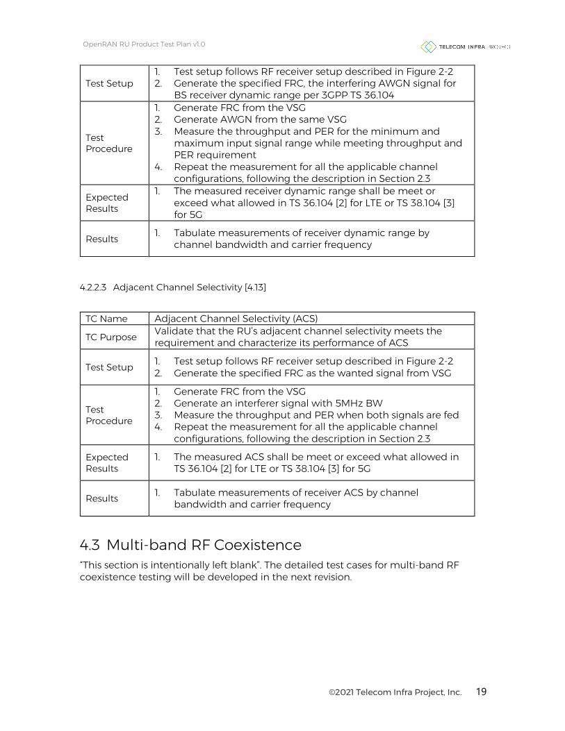
4.2.2.2 Receiver Dynamic Range [4.12]
TC Name Receiver Dynamic Range
TC Purpose Validate that the RU’s receiver dynamic range meets the requirement and characterize its performance of receiver dynamic range
©2021 Telecom Infra Project, Inc. 19
OpenRAN RU Product Test Plan v1.0
Test Setup 1. Test setup follows RF receiver setup described in Figure 2-2 2. Generate the specified FRC, the interfering AWGN signal for
BS receiver dynamic range per 3GPP TS 36.104
Test Procedure
1. Generate FRC from the VSG 2. Generate AWGN from the same VSG 3. Measure the throughput and PER for the minimum and
maximum input signal range while meeting throughput and PER requirement
4. Repeat the measurement for all the applicable channel configurations, following the description in Section 2.3
Expected Results
1. The measured receiver dynamic range shall be meet or exceed what allowed in TS 36.104 [2] for LTE or TS 38.104 [3] for 5G
Results 1. Tabulate measurements of receiver dynamic range by channel bandwidth and carrier frequency
4.2.2.3 Adjacent Channel Selectivity [4.13]
TC Name Adjacent Channel Selectivity (ACS)
TC Purpose Validate that the RU’s adjacent channel selectivity meets the requirement and characterize its performance of ACS
Test Setup 1. Test setup follows RF receiver setup described in Figure 2-2 2. Generate the specified FRC as the wanted signal from VSG
Test Procedure
1. Generate FRC from the VSG 2. Generate an interferer signal with 5MHz BW 3. Measure the throughput and PER when both signals are fed 4. Repeat the measurement for all the applicable channel
configurations, following the description in Section 2.3
Expected Results
1. The measured ACS shall be meet or exceed what allowed in TS 36.104 [2] for LTE or TS 38.104 [3] for 5G
Results 1. Tabulate measurements of receiver ACS by channel bandwidth and carrier frequency
4.3 Multi-band RF Coexistence “This section is intentionally left blank”. The detailed test cases for multi-band RF coexistence testing will be developed in the next revision.

©2021 Telecom Infra Project, Inc. 20
OpenRAN RU Product Test Plan v1.0
5 Digital Board Test Cases 5.1 Multi Carrier Configuration
5.1.1 Maximum Number of LTE Carriers [5.1] TC Name Maximum Number of LTE Carriers
TC Purpose Validate that the RU shall support the maximum number of LTE carriers as specified
Test Setup 1. Test setup follows RF Transmit setup described in Figure 2-1 2. Transmit ETM1.1
Test Procedure
1. O-DU emulator is configured to transmit ETM1.1 from N LTE carriers with center frequencies f1, f2, …, fN and bandwidth BW1, BW2 , …, BWN simultaneously, starting from 2 carriers with N = 2
2. Configure the RU to transmit N LTE carriers with the total aggerated BW less or equal to the specified OBW requirement
3. Measure the OBW of all N carriers 4. Repeat Steps 1 to 3 with increasing number of LTE carriers in
the step size of 1 until reaching the maximum number of supported LTE carriers
Expected Results
1. All configured LTE carriers operate normally with its specified BW
2. The number of supported LTE carriers shall meet the maximum number of LTE carriers specified in the RU requirements document
Results 1. Record the maximum number of LTE carriers that can be supported
5.1.2 Maximum Number of NR Carriers [5.2] TC Name Number of NR Carriers
TC Purpose Validate that the RU shall support the maximum number of NR carriers as specified
Test Setup 1. Test setup follows RF Transmit setup described in Figure 2-1 2. Transmit ETM1.1
Test Procedure
1. O-DU emulator is configured to transmit ETM1.1 from N carriers with center frequencies f1, f2, …, fN and bandwidth BW1 , BW2 , …, BWN simultaneously, starting from 2 carriers with N = 2
2. Configure the RU to transmit N NR carriers with the total aggerated BW less or equal to the specified OBW requirement
3. Measure the OBW of all N carriers 4. Repeat Steps 1 to 3 with increasing number of NR carriers in
the step size of 1 until reaching the maximum number of supported NR carriers

©2021 Telecom Infra Project, Inc. 21
OpenRAN RU Product Test Plan v1.0
Expected Results
1. All configured NR carriers operate normally with its specified BW
2. The number of supported NR carriers shall meet the maximum number of NR carriers specified in the RU requirements document
Results 1. Record the maximum number of NR carriers that can be supported
5.1.3 Maximum Number of LTE and NR Carriers [5.3] TC Name Number of LTE and NR Carriers
TC Purpose Validate that the RU shall support the maximum number of LTE and NR carriers simultaneously as specified
Test Setup 1. Test setup follows RF Transmit setup described in Figure 2-1 2. Transmit ETM1.1
Test Procedure
1. O-DU emulator is configured to transmit ETM1.1 from N LTE carriers with center frequencies f1, f2, …, fN and bandwidth BW1 , BW2 , …, BWN simultaneously, and M NR carriers with center frequencies f1, f2, …, fM and bandwidth BW1 , BW2 , …, BWM starting from 2 LTE carriers and 2 NR carriers with N = 2 and M = 2
2. Configure the RU to transmit N LTE carriers and M NR carriers with the total aggerated BW less or equal to the specified OBW requirement
3. Measure the OBW of all N + M carriers 4. Repeat Steps 1 to 3 with increasing number of carriers in the
step size of 1 until reaching the maximum number of supported LTE and NR carriers
Expected Results
1. All configured LTE and NR carriers operate normally with its specified BW
2. The number of supported LTE and NR carriers shall meet the maximum number of LTE and NR carriers specified in the RU requirements document
Results 1. Record the maximum number of LTE and NR carriers that can be supported
5.2 O-RAN Fronthaul The O-RAN fronthaul conformance and IOT test cases should follow O-RAN fronthaul test specifications [6] and [7], respectively. This section only specifies the minimum set of O-RAN fronthaul test cases, and is not intended as substitute for O-RAN fronthaul conformance and IOT test plans as defined in [6] or [7]. When applicable, O-RAN fronthaul conformance and IOT test reports are required to ensure full compliance to O-RAN fronthaul specifications.

©2021 Telecom Infra Project, Inc. 22
OpenRAN RU Product Test Plan v1.0
For test cases referred to O-RAN test specifications, test setup, procedure and expected results shall be consistent with what defined in the specific sections in the specifications. Table 5-1 lists O-RAN fronthaul test cases below.
Table 5-1: O-RAN Fronthaul Conformance and IOT Test Cases [5.4-5.7, 5.9-5.16]
Test Category
TC Title TC Purpose O-RAN Specification
S Plane Functional test of RU using LLS-C1/C2/C3
Validate that RU supports synchronization using ITU-T G.8275.1 profile (LLS-C1/C2/C3)
Refer to [6], Section 3.3.2
Performance test of O-RU using LLS-C1/C2/C3
Validate that frequency and time error using LLS-C1/C3/C3 is within specified limits
Refer to [6], Section 3.3.3
C/U Plane
Delay Management – maximum FH Delay
Validate that correct timing is achieved with maximum fronthaul latency
Refer to [7], Section 2.2.4.4
Delay Management – minimum FH Delay
Validate that correct timing is achieved with minimum fronthaul latency
Refer to [7], Section 2.2.4.3
M-Plane Start-up in Hierarchical Mode
Validate that RU can start up in hierarchical mode and get in service successfully
Refer to [7] Section 2.2.1.1
Start-up in Hybrid Mode
Validate that RU can start up in hybrid mode and get in service successfully
Refer to [7] Section 2.2.1.2
Transport and Handshake in IPv4 Environment
Validate that the RU can execute the session establishment procedure with VLANs and a DHCPv4 server
Refer to [6], Section 3.1.1.1
Transport and Handshake in IPv6 Stateful Configuration Environment
Validate that the RU can execute the session establishment procedure with VLANs and a DHCPv6 server
Refer to [6], Section 3.1.1.3
SW Update (Positive Case)
Validate that the RU can successfully download and install SW
Refer to [6], Section 3.1.6.1
SW Activation without Reset
Validate that RU can successfully activate SW in a specific slot
Refer to [6], Section 3.1.7.1
O-RU Alarm Notification Generation
Validate that O-RU NETCONF server properly sends alarm notification
Refer to [6] Section 3.1.5.1
©2021 Telecom Infra Project, Inc. 23
OpenRAN RU Product Test Plan v1.0
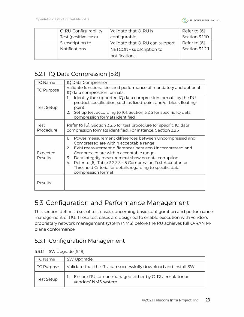
O-RU Configurability Test (positive case)
Validate that O-RU is configurable
Refer to [6] Section 3.1.10
Subscription to Notifications
Validate that O-RU can support NETCONF subscription to notifications
Refer to [6] Section 3.1.2.1
5.2.1 IQ Data Compression [5.8] TC Name IQ Data Compression
TC Purpose Validate functionalities and performance of mandatory and optional IQ data compression formats
Test Setup
1. Identify the supported IQ data compression formats by the RU product specification, such as fixed-point and/or block floating-point
2. Set up test according to [6], Section 3.2.5 for specific IQ data compression formats identified
Test Procedure
Refer to [6], Section 3.2.5 for test procedure for specific IQ data compression formats identified. For instance, Section 3.25
Expected Results
1. Power measurement differences between Uncompressed and Compressed are within acceptable range
2. EVM measurement differences between Uncompressed and Compressed are within acceptable range
3. Data integrity measurement show no data corruption 4. Refer to [6], Table 3.2.3.3 – 5 Compression Test Acceptance
Threshold Criteria for details regarding to specific data compression format
Results
5.3 Configuration and Performance Management This section defines a set of test cases concerning basic configuration and performance management of RU. These test cases are designed to enable execution with vendor’s proprietary network management system (NMS) before the RU achieves full O-RAN M-plane conformance.
5.3.1 Configuration Management
5.3.1.1 SW Upgrade [5.18]
TC Name SW Upgrade
TC Purpose Validate that the RU can successfully download and install SW
Test Setup 1. Ensure RU can be managed either by O-DU emulator or vendors’ NMS system

©2021 Telecom Infra Project, Inc. 24
OpenRAN RU Product Test Plan v1.0
Test Procedure
1. Select the RU SW version for upgrade either through O-DU emulator or NMS
2. Initialize the RU SW upgrade process 3. Verify that RU comes up back to operational state after the
upgrade process is completed
Expected Results
1. Once the SW upgrade process is completed, verify that the RU is installed with the chosen SW version
2. RU is in normal operation after the grade
Results
5.3.1.2 Remote Reboot [5.19]
TC Name Remote Reboot
TC Purpose Validate that the RU can be rebooted remotely
Test Setup 1. Ensure RU can be managed either by O-DU emulator or
vendors’ NMS system 2. RU is in normal operation
Test Procedure 1. Initialize a remote RU reboot through NMS or O-DU emulator
Expected Results
1. RU reboot can be triggered remotely 2. RU resumes normal operation successfully after the reboot
Results
5.3.1.3 RU Configuration [5.20]
TC Name RU Configuration
TC Purpose Validate that the RU can be configured with basis RF parameters
Test Setup 1. Ensure RU can be managed either by O-DU emulator or
vendors’ NMS system 2. RU is in normal operation
Test Procedure
1. Select basic RF configuration parameters, e.g. RAT, number of carriers, center frequency, channel BW, Tx power etc.
2. Apply the selected changes to the RU, and reboot the RU if necessary
3. Verify that RU comes up back to normal operation state with desirable changes
Expected Results
1. Verify that basic RF configuration changes can take effect after being applied to the RU
Results

©2021 Telecom Infra Project, Inc. 25
OpenRAN RU Product Test Plan v1.0
5.3.2 Performance Management
5.3.2.1 Performance Log [5.21]
TC Name Performance Log
TC Purpose Validate that the performance log can be configurable with different log levels and reflect RU operational metric
Test Setup 1. Ensure RU can be managed either by O-DU emulator or
vendors’ NMS system 2. RU is in normal operation
Test Procedure
1. Apply the selected log levels and interval to the RU 2. Verify that the performance log reflects correctly operational
metrics, e.g. Tx power, fronthaul packet transmission, timing/sync state etc.
Expected Results
1. The level and time interval of logging can be configured 2. The performance log reflects correctly the operational metric
observed
Results
5.3.2.2 Event Log [5.22]
TC Name Event Log
TC Purpose Validate that the event log can record the configuration changes and alarms triggered across the duration of testing.
Test Setup 1. Ensure RU can be managed either by O-DU emulator or
vendors’ NMS system 2. RU is in normal operation
Test Procedure
1. Clear the event log of RU 2. Apply a series of predetermined configuration changes to RU 3. Verify that the event log matches correctly to the sequence of
configuration changes applied 4. Trigger a series of alarm events to the RU, e.g. loss of sync,
fronthaul outage, VSWR alarm, etc.
Expected Results
1. The event log should reflect critical changes to operational configuration or significant alarm events with correct time stamp
2. The event log should reflect alarms triggered with correct alarm type, severity, alarm clearance and time stamp
Results

©2021 Telecom Infra Project, Inc. 26
OpenRAN RU Product Test Plan v1.0
6 Hardware 6.1 Interfaces
6.1.1 Fronthaul Optical Interface [6.1]
TC Name Fronthaul Optical Interface
TC Purpose To validate if all optical interfaces, 10G SFP+ or 25G SFP28, can be connected and configured for use
Test Setup
1. Connect RU optical port to the O-DU emulator through a switch with packet capturing capability
2. Connect a laptop installed with packet analyzer SW (e.g. Wireshark) to the switch
Test Procedure
1. Initialize packet capturing to capture all packet exchanges between the RU and O-DU emulator when the link comes up.
2. Monitor that the link comes up and the advertised rate via RU’s NMS
Expected Results
1. No physical port alarm, and the link comes up working fully functional
2. The line rate monitored is consistent with 10G SFP+ or 28G SFP28 depending on RU’s product capability, as indicated by RU’s NMS and analysis of packets captured
Results 1. Record the line rate and log captured packet file
6.2 Power Supply
6.2.1 DC Power Supply [6.2]
TC Name DC Power Supply
TC Purpose Validate that the power supply of RU meets the requirements of -48 VDC
Test Setup 1. Test setup follows RF Transmit setup described in Figure 2-1. 2. Transmit ETM1.1
Test Procedure
1. O-DU emulator is configured to transmit ETM1.1 2. The RU output is measured for OBW in spectrum analyzer 3. Configure the output voltage of DC power supply to the
minimum operating voltage specified. Observe the operation of the RU system through OBW measured by spectrum analyzer
4. Configure the output voltage of DC power supply to the maximum operating voltage specified. Observe the operation of the RU system through OBW measured by spectrum analyzer

©2021 Telecom Infra Project, Inc. 27
OpenRAN RU Product Test Plan v1.0
Expected Results
1. The RU shall operate normally in the range of voltages as specified in the RU requirements document
Results
6.2.2 Power Consumption [6.3]
TC Name Power Consumption & Power Efficiency
TC Purpose Characterize the power consumption of the RU and the corresponding RU power efficiency under various RF loading conditions
Test Setup 1. Test setup follows RF Transmit setup described in Figure 2-1. 2. Transmit ETM1.1
Test Procedure
1. O-DU emulator is configured to transmit ETM1.1 2. The RU output power is set accordingly 3. The RU output is measured for channel power in spectrum
analyzer 4. Measure the current, voltage and power consumption of the
RU by test instrument, such as power meter, clamp meter etc. Repeat the measurement for 3 times.
5. Repeat Step 1 – 4 for RF load condition of 25%, 50%, and 100% peak load. For instance, in the case of 4x40W Band 3 RU, three loading conditions are 4x10W, 4x20W and 4x40W
Expected Results
1. RU transmit channel power must be at its rated maximum output power as specified in the RU requirements document for peak power consumption and efficiency measurement
2. RU power efficiency at peak power is higher than 30%
Results
1. Record average power consumption of RU under different loads
2. Calculate RU’s power efficiency with various load as (Measured RF output power over all ports)/RU power consumption
6.3 Reliability
6.3.1 Long term Stability [6.4]
TC Name Long term Stability
TC Purpose Validate that the RU maintains its performance at its maximum rated power during a long-term test
Test Setup 1. Test setup follows RF Transmit setup described in Figure 2-1 2. Transmit ETM3.1a

©2021 Telecom Infra Project, Inc. 28
OpenRAN RU Product Test Plan v1.0
Test Procedure
1. O-DU emulator is configured to transmit ETM3.1a 2. RU is configured to transmit at its maximum rated power 3. Set the spectrum analyzer to measure EVM for 256QAM 4. Run the test for a minimum of 48 hours
Expected Results
1. No error or performance degradation observed during test period
Results
6.3.2 Power Outage Recovery [6.5]
TC Name Power Outage Recovery
TC Purpose Validate that RU can be rebooted remotely
Test Setup 1. RU is connected to DU in a E2E environment 2. RU is configured and in normal operation
Test Procedure
1. Unplug power supply to RU 2. Restore power supply to RU after 60 seconds
Expected Results
1. RU resumes normal operation successfully after the power
supply restores
Results
6.3.3 Fronthaul Outage Recovery [6.6] TC Name Fronthaul Outage Recovery
TC Purpose Validate that RU can recover from fronthaul outage
Test Setup 1. RU is connected to DU in a E2E environment 2. RU is configured and in normal operation
Test Procedure
1. Disconnect eCPRI SFP+ or SFP28 from RU 2. Reconnect eCPRI SFP+ or SPF28 to RU after 60 seconds
Expected Results
1. RU resume normal operation successfully after the power supply restores
2. RU’s NMS logs the alarm of fronthaul outage, and the subsequent fronthaul connection recovery
Results
©2021 Telecom Infra Project, Inc. 29
OpenRAN RU Product Test Plan v1.0
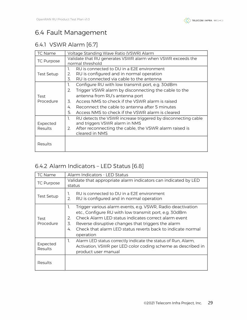
6.4 Fault Management
6.4.1 VSWR Alarm [6.7] TC Name Voltage Standing Wave Ratio (VSWR) Alarm
TC Purpose Validate that RU generates VSWR alarm when VSWR exceeds the normal threshold
Test Setup 1. RU is connected to DU in a E2E environment 2. RU is configured and in normal operation 3. RU is connected via cable to the antenna
Test Procedure
1. Configure RU with low transmit port, e.g. 30dBm 2. Trigger VSWR alarm by disconnecting the cable to the
antenna from RU’s antenna port 3. Access NMS to check if the VSWR alarm is raised 4. Reconnect the cable to antenna after 5 minutes 5. Access NMS to check if the VSWR alarm is cleared
Expected Results
1. RU detects the VSWR increase triggered by disconnecting cable and triggers VSWR alarm in NMS
2. After reconnecting the cable, the VSWR alarm raised is cleared in NMS
Results
6.4.2 Alarm Indicators – LED Status [6.8] TC Name Alarm Indicators - LED Status
TC Purpose Validate that appropriate alarm indicators can indicated by LED status
Test Setup 1. RU is connected to DU in a E2E environment 2. RU is configured and in normal operation
Test Procedure
1. Trigger various alarm events, e.g. VSWR, Radio deactivation etc., Configure RU with low transmit port, e.g. 30dBm
2. Check Alarm LED status indicates correct alarm event 3. Reverse disruptive changes that triggers the alarm 4. Check that alarm LED status reverts back to indicate normal
operation
Expected Results
1. Alarm LED status correctly indicate the status of Run, Alarm, Activation, VSWR per LED color coding scheme as described in product user manual
Results
©2021 Telecom Infra Project, Inc. 30
OpenRAN RU Product Test Plan v1.0
7 References [1] TIP OpenRAN RU Sub-group Requirements Document, Version 0.7, November 2020 [2] 3GPP TS 36.104, “Evolved Universal Terrestrial Radio Access (E-UTRA); Base Station(BS) radio transmission and reception”
[3] 3GPP TS 38.104, “NR; Base Station (BS) radio transmission and reception”
[4] 3GPP TS 36.141, “Evolved Universal Terrestrial Radio Access (E-UTRA); Base Station(BS) conformance testing”
[5] 3GPP TS 38.141-2, “NR; Base Station (BS) conformance testing Part 2: Radiated conformance testing” [6] O-RAN.WG4.CONF.0-v03.00 “Fronthaul Working Group Fronthaul Conformance Test Specification” Version 3, March 2021 [7] O-RAN.WG4.IOT.0-v04.00 “Fronthaul Working Group Fronthaul Interoperability Test Specification (IOT)” Version 4, March 2021

©2021 Telecom Infra Project, Inc. 31
OpenRAN RU Product Test Plan v1.0
8 Glossary 3GPP Third Generation Partnership Project
ACLR Adjacent Channel Leakage Ratio
ACS Adjacent Channel Selectivity
BW Bandwidth
CP control plane
CPRI Common Public Radio Interface
CU centralized unit
DHCP Dynamic Host Configuration Protocol
DU distributed unit
E2E End-to-End
eCPRI enhanced Common Public Radio Interface
eNB E-UTRAN Node B, a.k.a., Evolved Node B
EPC evolved packet core
ETM E-UTRA Test Model
EVM error vector magnitude
FH fronthaul
GNSS Global Navigation Satellite System
IBW Instantaneous Bandwidth
LLS-C1 Low Level Split – Configuration 1
LTE Long Term Evolution
NETCONF Network Configuration Protocol
NMS Network Management System
NR New Radio
OBW Occupied Bandwidth

©2021 Telecom Infra Project, Inc. 32
OpenRAN RU Product Test Plan v1.0
OpenRAN A vendor-neutral disaggregation of RAN at both the hardware and software levels on general purpose, processor-based platforms
PSU Power Supply Unit
RAN Radio Access Network
RAT Radio Access Technology
RF Radio Frequency
RU Radio Unit
Rx Receive
SA Spectrum Analyzer
SW software
Tx Transmit
UE user equipment
VLAN Virtual Local Area Network
VSA Vector Signal Analyzer
VSG Vector Signal Generator
VSWR Voltage Standing Wave Ratio