OPEN 3D MESH PARAMETERIZATION BASED ON EDGE RATIO … · OPEN 3D MESH PARAMETERIZATION BASED ON...
12
U.P.B. Sci. Bull., Series C, Vol. 73, Iss. 4, 2011 ISSN 1454-234x OPEN 3D MESH PARAMETERIZATION BASED ON EDGE RATIO PRESERVATION Bogdan MOCANU 1 , Ruxandra ŢAPU 2 , Teodor PETRESCU 3 În acest articol este implementat un nou algoritm de parametrizare plană. După o scurtă prezentare a cercetărilor actuale în acest domeniu, este descrisă noua noastră metodă de mapare baricentrică, bazată pe conservarea rapoartelor de lungimi între muchiile modelelor 3D. Rezultatele obţinute prin implementarea algoritmului propus certifică superioritatea noii metode faţă de majoritatea tehnicilor de parametrizare publicate până în prezent în literatura de specialitate, reducând cu mai mult de 78% şi 57% distorsiunile de arii şi lungimi, menţinând în acelaşi timp distorsiunile de unghiuri la valori reduse. În plus metoda noastră returnează rezultate valide de parametrizare indiferent de complexitatea modelelor 3D. In this paper we introduce a new 3D planar parameterization algorithm. After presenting a brief overview of the state of the art, we introduce a new barycentric mapping method, based on the edge length ratio preservation. Our proposed approach demonstrate higher performances with respect to all main techniques developed so far in this direction, reducing both area and length distortions with more than 78% and 57% respectively, maintaining in the same time a low value for the angular distortion. Moreover, our method ensures valid embeddings for any arbitrary open 3D mesh, regardless its complexity. Keywords: planar parameterization, barycentric coordinates, length ratio preservation 1. Introduction Tridimensional mesh parameterization represents an important step that needs to be implemented in various applications such as: remeshing, recognition, morphing. From a mathematical point of view, a parameterization of a 3D mesh M is defined as a homeomorphism f param :M→D which maps the 3D mesh M over an 1 Assistant, Faculty of Electronics, Telecommunications and Information Technology, University POLITEHNICA of Bucharest, Romania, e-mail: [email protected] 2 Assistant, Faculty of Electronics, Telecommunications and Information Technology, University POLITEHNICA of Bucharest, Romania, e-mail: [email protected] 3 Prof., Faculty of Electronics, Telecommunications and Information Technology, University POLITEHNICA of Bucharest, Romania, e-mail: [email protected]
Transcript of OPEN 3D MESH PARAMETERIZATION BASED ON EDGE RATIO … · OPEN 3D MESH PARAMETERIZATION BASED ON...

U.P.B. Sci. Bull., Series C, Vol. 73, Iss. 4, 2011 ISSN 1454-234x
OPEN 3D MESH PARAMETERIZATION BASED ON EDGE RATIO PRESERVATION
Bogdan MOCANU1, Ruxandra ŢAPU2, Teodor PETRESCU3
În acest articol este implementat un nou algoritm de parametrizare plană. După o scurtă prezentare a cercetărilor actuale în acest domeniu, este descrisă noua noastră metodă de mapare baricentrică, bazată pe conservarea rapoartelor de lungimi între muchiile modelelor 3D. Rezultatele obţinute prin implementarea algoritmului propus certifică superioritatea noii metode faţă de majoritatea tehnicilor de parametrizare publicate până în prezent în literatura de specialitate, reducând cu mai mult de 78% şi 57% distorsiunile de arii şi lungimi, menţinând în acelaşi timp distorsiunile de unghiuri la valori reduse. În plus metoda noastră returnează rezultate valide de parametrizare indiferent de complexitatea modelelor 3D.
In this paper we introduce a new 3D planar parameterization algorithm. After presenting a brief overview of the state of the art, we introduce a new barycentric mapping method, based on the edge length ratio preservation. Our proposed approach demonstrate higher performances with respect to all main techniques developed so far in this direction, reducing both area and length distortions with more than 78% and 57% respectively, maintaining in the same time a low value for the angular distortion. Moreover, our method ensures valid embeddings for any arbitrary open 3D mesh, regardless its complexity.
Keywords: planar parameterization, barycentric coordinates, length ratio preservation
1. Introduction
Tridimensional mesh parameterization represents an important step that needs to be implemented in various applications such as: remeshing, recognition, morphing.
From a mathematical point of view, a parameterization of a 3D mesh M is defined as a homeomorphism fparam:M→D which maps the 3D mesh M over an
1 Assistant, Faculty of Electronics, Telecommunications and Information Technology, University
POLITEHNICA of Bucharest, Romania, e-mail: [email protected] 2 Assistant, Faculty of Electronics, Telecommunications and Information Technology, University
POLITEHNICA of Bucharest, Romania, e-mail: [email protected] 3 Prof., Faculty of Electronics, Telecommunications and Information Technology, University
POLITEHNICA of Bucharest, Romania, e-mail: [email protected]
170 Bogdan Mocanu, Ruxandra Ţapu, Teodor Petrescu
appropriate 2D domain D. The mesh M is defined as a set of vertices pi in IR3 together with its connectivity, specified by:
- the set of triangles F=F(f0(pi,pj,pk),…,fm(ps,pt,pu), and - the set of edges E=E(ek(p’
k,p”k))).
The parametric domain D is selected in most of the cases depending on the original model topology. For open triangular meshes, the most intuitive way to obtain a parameterization is to map its vertices in a planar domain. In the case of closed 3D objects, a spherical domain (e.g., the unit sphere) is more appropriate.
As a homeomorphism the mapping is bijective, thus paramf is continuous and piecewise linear. Thus, the parameterization is uniquely defined by specifying the parameter points φi = fparam(pi) for each vertex pi(xi, yi, zi)∈VM. The bijection is required because each triangle of the mesh need to have an appropriate image in the parameter domain. In other words, the faces must not overlap. In practice, there are some circumstances when the obtained function is not continuous or bijective and this will lead to an invalid parameterization. Numerous approaches in the literature aim at preventing triangles flipping problems. However, a crucial issue when considering 3D parametrization techniques concerns the minimization of several distortion measures. The distortions can be defined as the degree of deformation, in terms of angles, areas and lengths between the original 3D shape model and the resulted parameterized mesh. In this context, we can distinguish three categories of distortion measures, which correspond to conformal, equiareal and isometric mappings.
After a complete evaluation of the most powerful methods existing in the technical literature, we will propose and validate in this paper, a novel and nearly isometric parameterization technique for open 3D triangular meshes based on edge length ratio preservation.
The rest of this paper is organized as follows: after a review of the planar mapping approaches, in Section III we introduce the proposed method. Section IV presents a comparative experimental evaluation, carried out on a subset of 3D objects selected from the Princeton and MPEG 7 database. Finally, Section V concludes our paper and opens perspective of future work.
2. Previous work
The first parameterization methods [1, 2, 3] proposed in the specialized literature were directed to planar mapping of meshes with disk-like topology. These approaches are based on the idea that a mesh connectivity can be compared with a system where edges are springs linking the model vertices.
A generic technique to embed a 3D mesh with a boundary into a plane was proposed by Eck et al. in [4]. By generalizing the Tutte planar graph algorithm [5], the principle consists of minimizing the spring system energy (based on

Open 3D mesh parameterization based on edge ratio preservation 171
partial derivatives) in the parametric domain. Here, the boundary vertices are considered fixed and their position is precomputed at the beginning. Because every point in the parameter domain is placed at the center of its neighbors, this method was denoted barycentric mapping. Although the mapping is bijective, the major drawback consists in not fulfilling the minimization requirements, causing high values of the distortion, because the method does not take into account the model’s geometry.
Considering this, many attempts were elaborated in order to obtain the best shape preserving parameterization. The discrete harmonic mapping introduced by Pinkall and Polthier in [1] uses differential geometry to minimize the Dirichlet energy of a piecewise linear embedding. In theory, the technique is angle preserving, but due to the fixed boundary vertices near the frontier the distortion has high values in terms of both area and angles. To reduce as much as possible this drawback Debrun et al. [2] proposed to determine the boundary vertices position as a part of a minimization procedure (discrete conformal mapping). The process returns a better parameterization in terms of robustness. The price to pay is the increased computational complexity.
Both harmonic and conformal mapping conserve the model shape, but not its original areas. Moreover, as it was demonstrated by Floater in [3] there are some cases for which the mapping is not bijective (negative weights) and the triangles overlap.
Thereby, before using the discrete conformal mapping, it is necessary to verify if the mesh topology satisfies the Delaunay triangulation [6]. Kharevych et al. [7] demonstrate that if the mesh satisfies the Delaunay criterion, the parameterization obtained using the cotangent weights proposed in [2] will always be bijective.
The mean value coordinates technique first introduced by Floater in [8] aims to preserve the model angles by developing a generalized barycentric coordinate system which expresses a vertex as a linear combination of its neighbors. With the new set of weights the resulting system guarantees a bijective mapping for any type of open 3D models. However, in practice this technique returns less satisfactory result than the classical harmonic mapping [1].
The angle based flattening (ABF) algorithm proposed by Sheffer and Sturler [9] defines the parameterization in terms of angles distortion by satisfying a set of constraints. The resulted mapping guarantees a local bijectivity, but not a global one. Unfortunately, in practice the method proves to be time consuming. In addition, for meshes with a large number of vertices the system stability becomes a problem.
An improved technique is presented in [10] called ABF++ that solves the above-mentioned limitation by simplifying the coordinates system that needs to be solved at each iteration into a linear form.
172 Bogdan Mocanu, Ruxandra Ţapu, Teodor Petrescu
Another class of planar parameterization methods is based on the so-called discrete authalic map, also called equiareal mapping. Such techniques lead to an area preserving parameterization. However, in [11] Floater proved that equiareal mappings, unlike conformal ones, are not unique. For this reason, additional conditions/constraints should be imposed in order to obtain stable and computationally tractable solutions. Notably, numerous approaches propose to combine the angular distortion minimization techniques with area-preserving ones [2], [12], [13], [14], [15].
As representative of such methods, let us cite the technique proposed by Desbrun et al. [2]. Authors introduce a mechanism assuring a trade-off between angle and area distortions in order to determine an optimal mapping of a 3D object into the parametric domain. The technique combines the conformal mapping with a metric that preserves the areas, resulting in a joined convex combination. However, the method measures deformations in the area distribution only locally within each one-ring. In this way, the approach accumulates a small error with each local deformation, causing an unbalanced global area distribution.
The method proposed in this paper and described in the next section also belongs to this family of approaches. Our technique attempts to jointly minimize angle and area distortion based on edge length ratios.
3. Planar parameterization based on edge length ratio preserving
We will present further the general mathematical support necessary to establish the energy spring system. Next we will focus our attention on most encounter weights that influence the relaxation process, while in the final part we introduce our new set of weights determined based on the local geometry of the original model ensuring a robust parameterization.
3.1. Spring system construction
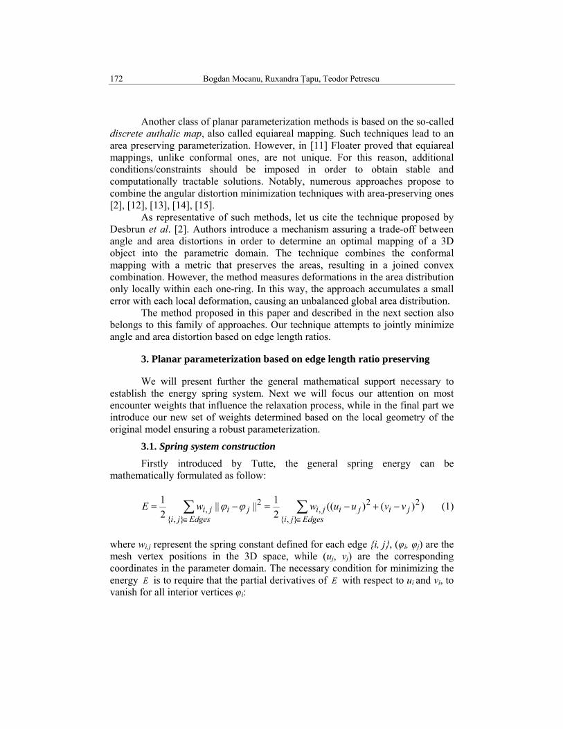
Firstly introduced by Tutte, the general spring energy can be mathematically formulated as follow:
∑∑∈∈
−+−=−=Edgesji
jijijiEdgesji
jiji vvuuwwE},{
22,
},{
2, ))()((
21||||
21 ϕϕ (1)
where wi,j represent the spring constant defined for each edge {i, j}, (φi, φj) are the mesh vertex positions in the 3D space, while (uj, vj) are the corresponding coordinates in the parameter domain. The necessary condition for minimizing the energy E is to require that the partial derivatives of E with respect to ui and vi, to vanish for all interior vertices φi:

Open 3D mesh parameterization based on edge ratio preservation 173
0)(221
0)(221
)(,
)(,
=−=∂∂
=−=∂∂
∑
∑
∈
∈
iNeighborsjjiji
i
iNeighborsjjiji
i
vvwEv
uuwEu (2)
If we analyze (2), we can see that every inner vertex can be expressed as a
convex linear combination of its neighbors:
∑∑
∑∑
∈∈
∈∈
=⇒=−
=⇒=−
)(,
)(,
)(,
)(,
0)(
0)(
iNeighborsjjjii
iNeighborsjjiji
iNeighborsjjjii
iNeighborsjjiji
vvvvw
uuuuw
λ
λ
(3)
where with j,iλ we denote the normalized spring weights for an edge {i, j}:
∑∈
=)(
,,, /iNeigborskkijiji wwλ (4)
It is easy to observe that: ∑
∈=)(
, 1iNeighborsj
jiλ (5)
In eq (3), if we consider N the total number of mesh vertices and n the
number of inner vertices (i.e., non boundary points), then we can separate the interior and the boundary vertices in the sum in the following manner:
∑∑
∑∑
>∈
≤∈
>∈
≤∈
=−
=−
njiNeighborsj
jji
njiNeighborsj
jjii
njiNeighborsj
jji
njiNeighborsj
jjii
vvv
uuu
)(,
)(,
)(,
)(,
λλ
λλ
(6)
By writing the eq. (6) for all interior vertices, we obtain two linear systems
of equations, expressed in the matrix form as follows:
UBUA =⋅ and VBVA =⋅ (7) where the unknown U=[u1,u2,...,un]T and V=[v1,v2,...,vn]T are columns vectors corresponding to coordinates in the parameter domain D ; Bu=[bu1,bu2,...,bun]T and Bv=[bv1,bv2,...,bvn]T are columns vectors with coefficients:
174 Bogdan Mocanu, Ruxandra Ţapu, Teodor Petrescu
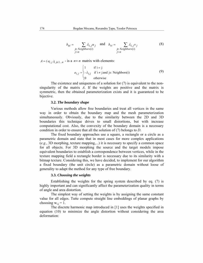
∑>∈
=
njiNeighborsj
jjiui ub)(
,λ and ∑>∈
=
njiNeighborsj
jjivi vb)(
,λ (8)
n...j,ij,i )a(A 1∈= - is a nn× matrix with elements:
⎪⎩
⎪⎨
⎧
∈≠=
=
otherwise 0
i)Neighbors(j and j i if -ji if 1
ji,, λjia (9)
The existence and uniqueness of a solution for (7) is equivalent to the non-singularity of the matrix A. If the weights are positive and the matrix is symmetric, then the obtained parameterization exists and it is guaranteed to be bijective.
3.2. The boundary shape
Various methods allow free boundaries and treat all vertices in the same way in order to obtain the boundary map and the mesh parameterization simultaneously. Obviously, due to the similarity between the 2D and 3D boundaries this technique drives to small distortions, but with increase computational cost. Also, the convexity of the boundary domain is a necessary condition in order to ensure that all the solution of (7) belongs to D.
The fixed boundary approaches use a square, a rectangle or a circle as a parametric domain and state that in most cases for more complex applications (e.g., 3D morphing, texture mapping,...) it is necessary to specify a common space for all objects. For 3D morphing the source and the target models impose equivalent boundaries to establish a correspondence between vertices, while in the texture mapping field a rectangle border is necessary due to its similarity with a bitmap texture. Considering this, we have decided, to implement for our algorithm a fixed boundary (the unit circle) as a parametric domain without loose of generality to adapt the method for any type of free boundary.
3.3. Choosing the weights Establishing the weights for the spring system described by eq. (7) is
highly important and can significantly affect the parameterization quality in terms of angle and area distortion.
The simplest way of setting the weights is by assigning the same constant value for all edges. Tutte compute straight line embeddings of planar graphs by choosing wi,j = 1.
The discrete harmonic map introduced in [1] uses the weights specified in equation (10) to minimize the angle distortion without considering the area deformation:

Open 3D mesh parameterization based on edge ratio preservation 175
ijijjiw βα cotcot, += (10)
where αij and βij are the opposite angles of the two triangles that share the same edge {i, j} (Fig. 1).
The mean value coordinates proposed by Floater in [8] are defined as:
||||
)22
tan( ,,
,ji
jiji
jiwϕϕ
δγ
−
+= (11)
where γi,j and δi,j are the angles in the two triangles shared by the edge {i, j} as shown in Fig. 1.
All the above presented methods return less satisfactory results when
considering the area distortion criterion. In order to overcome this drawback we propose a new set of weights that minimize the areas deformation while maintaining a low angle distortion. The proposed technique can be applied to any type of 3D open models assuring a valid parameterization (bijective mapping) with a reduced computation cost.
Each inner vertex of a mesh can be expressed as a linear combination of its neighbors. In our implementation the weight is computed as the ratio of the distance between the current vertex pi and an adjacent point pj reported to the total sum of lengths for all edges converging in pi (Fig. 2).
∑∈
=
)(iNeighborsjij
ijij l
lw (12)
When using the above weights, eq. (3) can be rewritten:
ip
jp
jiαjiβji ,γ
ji ,δ
Fig. 2. The one ring neighbors of vertex pi and the associated lengths
Fig. 1. Angles used for weights computation
Pi
PinPi1
Pi2li1
li2lin
176 Bogdan Mocanu, Ruxandra Ţapu, Teodor Petrescu
00)(
,)(
)(
)(,
=+−⇒=− ∑∑∑
∑
∈∈∈
∈
iNeighborsjjji
iNeighborsjiji
iNeighborsjij
iNeighborsjjji
i ullul
ul
u (13)
Also, vi can be expressed in a similar way. As it can be observed, in this case the resulting system is symmetric and all elements from A matrix, excepting the main diagonal are positive, which guarantees the bijectivity of our parameterization. Further more the resulted matrix contains only a few non-zero elements, depending on the adjacent vertices. The above observations allow us to compute the spring system solution by using the conjugate gradient method that iteratively solves the sparse linear system.
4. Experiments and results
In order to evaluate the proposed parameterization algorithm we have considered a subset of objects from the Princeton Shape Benchmark which is freely available over the Internet (http://shape.cs.princeton.edu/benchmark/) and from the MPEG 7 3D model test set. The selected objects are open manifold triangular mesh models characterized by complex structure which include various types of concavities that allow us to demonstrate the performance of our improved planar mapping.
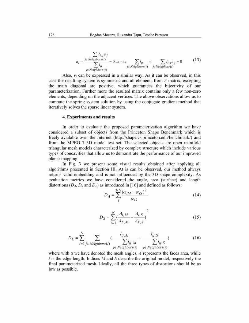
In Fig. 3 we present some visual results obtained after applying all algorithms presented in Section III. At is can be observed, our method always returns valid embedding and is not influenced by the 3D shape complexity. As evaluation metrics we have considered the angle, area (surface) and length distortions (DA, DS and DL) as introduced in [16] and defined as follows:
∑⋅ −
=N
i iS
iSiMAD
3 2)(ααα
(14)
2
1 ,
,
,
, )(∑=
−=N
i ST
Si
MT
MiS A
AAA
D (15)
∑ ∑ ∑∑= ∈∈∈
−=N
i iNeighborsjiNeighborsj
Sij
Sij
iNeighborsjMij
MijL l
ll
lD
1 )()(
,
,
)(,
, )( (16)
where with α we have denoted the mesh angles, A represents the faces area, while l is the edge length. Indices M and S describe the original model, respectively the final parameterized mesh. Ideally, all the three types of distortions should be as low as possible.
Open 3D mesh parameterization based on edge ratio preservation 177
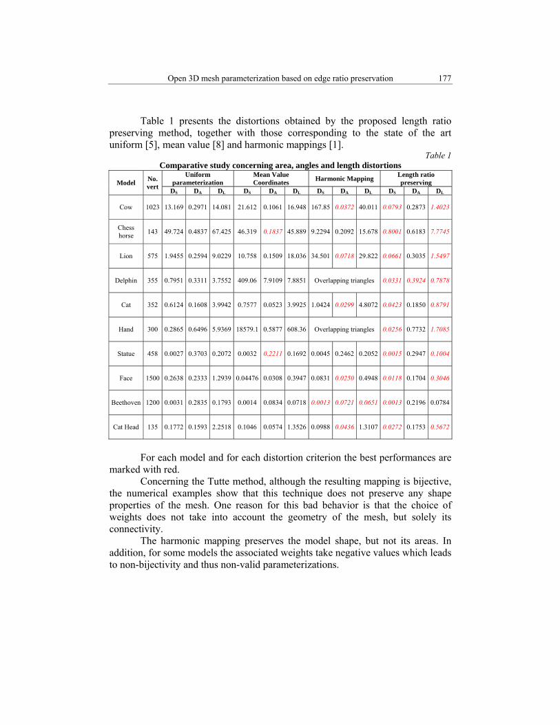
Table 1 presents the distortions obtained by the proposed length ratio preserving method, together with those corresponding to the state of the art uniform [5], mean value [8] and harmonic mappings [1].
Table 1 Comparative study concerning area, angles and length distortions
Model No. vert
Uniform parameterization
Mean Value Coordinates Harmonic Mapping Length ratio
preserving DS DA DL DS DA DL DS DA DL DS DA DL
Cow 1023 13.169 0.2971 14.081 21.612 0.1061 16.948 167.85 0.0372 40.011 0.0793 0.2873 1.4023
Chess horse 143 49.724 0.4837 67.425 46.319 0.1837 45.889 9.2294 0.2092 15.678 0.8001 0.6183 7.7745
Lion 575 1.9455 0.2594 9.0229 10.758 0.1509 18.036 34.501 0.0718 29.822 0.0661 0.3035 1.5497
Delphin 355 0.7951 0.3311 3.7552 409.06 7.9109 7.8851 Overlapping triangles 0.0331 0.3924 0.7878
Cat 352 0.6124 0.1608 3.9942 0.7577 0.0523 3.9925 1.0424 0.0299 4.8072 0.0423 0.1850 0.8791
Hand 300 0.2865 0.6496 5.9369 18579.1 0.5877 608.36 Overlapping triangles 0.0256 0.7732 1.7085
Statue 458 0.0027 0.3703 0.2072 0.0032 0.2211 0.1692 0.0045 0.2462 0.2052 0.0015 0.2947 0.1004
Face 1500 0.2638 0.2333 1.2939 0.04476 0.0308 0.3947 0.0831 0.0250 0.4948 0.0118 0.1704 0.3046
Beethoven 1200 0.0031 0.2835 0.1793 0.0014 0.0834 0.0718 0.0013 0.0721 0.0651 0.0013 0.2196 0.0784
Cat Head 135 0.1772 0.1593 2.2518 0.1046 0.0574 1.3526 0.0988 0.0436 1.3107 0.0272 0.1753 0.5672
For each model and for each distortion criterion the best performances are
marked with red. Concerning the Tutte method, although the resulting mapping is bijective,
the numerical examples show that this technique does not preserve any shape properties of the mesh. One reason for this bad behavior is that the choice of weights does not take into account the geometry of the mesh, but solely its connectivity.
The harmonic mapping preserves the model shape, but not its areas. In addition, for some models the associated weights take negative values which leads to non-bijectivity and thus non-valid parameterizations.
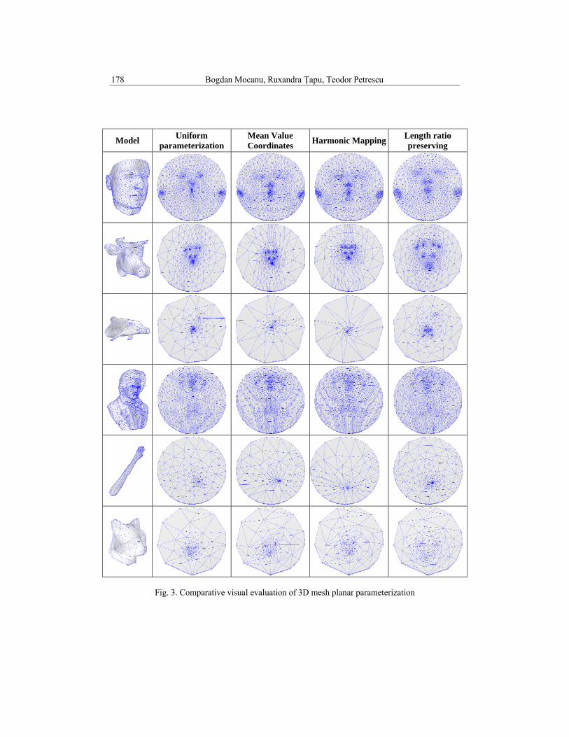
178 Bogdan Mocanu, Ruxandra Ţapu, Teodor Petrescu
Fig. 3. Comparative visual evaluation of 3D mesh planar parameterization
Model Uniform parameterization
Mean Value Coordinates Harmonic Mapping Length ratio
preserving

Open 3D mesh parameterization based on edge ratio preservation 179
In the case of mean value coordinates even though the resulted matrix loose the symmetric property, the resulted embedding is valid in all cases. However, the major drawback of this method is related to the computational complexity because in this situation it is impossible to use the fast conjugate gradient algorithm to solve the linear systems involved.
The analysis of the results obviously shows that the proposed length ration method outperform the other approaches in the case of both aria (with a 78,5 % reduction) and length (with a 57% reduction) distortions.
For the angle distortion, the best performances are achieved by the harmonic mapping technique. However, the harmonic mapping fails in the case of some models due to the negative weights in the energy spring system. Thus, our method offers the advantage of a larger applicability.
6. Conclusions and perspectives
In this paper we have proposed an enhanced 3D object planar parameterization method based on the mesh edges length ratio preservation.
The experimental results were carried out on more then 25 models, some of them presented in Fig. 3. These are sufficient to demonstrate the superiority of our method compared with all of the state of the art algorithms by providing low distortions rates in terms of area and lengths especially for complex objects with reduction of more then 78,5% and 57% respectively.
Our future work will concern the integration of our algorithm in a more general framework of mesh morphing applications by resolving the correspondence step between two topological different models. Furthermore, we plan to develop a new parameterization method applicable for closed genus-0 manifold triangular mesh models by extending the method proposed in this paper.
R E F E R E N C E S
[1] U. Pinkall, K. Polthier, Computing discrete minimal surfaces and their conjugates, Experiment Mathematics, vol. 2, 1993, pp. 15-36.
[2] M. Desbrun, M. Meyer, P. Alliez, Intrinsic Parameterizations of Surface Meshes, Computer Graphics Forum, vol. 21, 2002, pp. 210-218.
[3] M.S. Floater, Parametrization and smooth approximation of surface triangulations, Computer Aided Geometric Design, vol. 14, no. 3, 1997, pp. 231-250.
[4] M. Eck, T. DeRose, T. Duchamp, H. Hoppe, M. Lounsbery, W. Stuetzle, Multiresolution analysis of arbitrary meshes, Proceedings of SIGGRAPH, 1995, pp. 173–182.
[5] W.T. Tutte, How to draw a graph. Proceedings on the London Mathematical Society, vol. 3, 1963, pp. 743-768.
[6] B. Delaunay, "Sur la sphère vide", Bulletin of the Academy of Sciences of the U.S.S.R., Classe des Sciences Mathématiques et Naturelle, vol. 7, no. 6, 1934, pp. 793-800.
[7] L. Kharevych, B. Springborn, P. Schröder, Discrete conformal mappings via circle patterns, ACM Transactions on Graphics, vol. 25, no. 2, 2006, pp. 412-438.
180 Bogdan Mocanu, Ruxandra Ţapu, Teodor Petrescu
[8] M. Floater, Mean value coordinates, In Computer Aided Geometric Design, vol. 20, 2003, pp. 19-27.
[9] A. Sheffer, E. Sturler, Parameterization of faceted surfaces for meshing using angle-based flattening, Engineering with Computers, vol. 17, 2001, pp. 326–337.
[10] A. Sheffer, B. Lévy, M. Mogilnitsky, A. Bogomyakov, ABF++: fast and robust angle based flattening, ACM Transactions on Graphics, vol. 24, no. 2, 2005, pp. 311–330.
[11] M. S. Floater, K. Hormann, Surface parameterization: a tutorial and survey, In Advances in Multiresolution for Geometric Modelling, Springer Verlag, 2005, pp. 157–186.
[12] N. Pietroni, M. Tarini, P. Cignoni, Almost isometric mesh parameterization through abstract domains, IEEE Transactions on Visualization and Computer Graphics, vol. 16, no. 4, 2010, pp. 621–635.
[13] A. Dominitz, A. Tannenbaum, Texture Mapping via Optimal Mass Transport, IEEE Transactions on Visualization and Computer Graphics, vol. 16, no. 3, 2010, pp. 419-33.
[14] P. Degener, J. Meseth, R. Klein, An Adaptable Surface Parameterization Method, Proceedings 12th International Meshing Roundtable, 2003, pp. 201-213.
[15] Y. L. Yang, J. Kim, F. Luo, S. M. Hu, X. Gu, Optimal surface parameterization using inverse curvature map, IEEE Transactions on Visualization and Computer Graphics, vol. 14, 2008, pp. 1054–1066.
[16] H. Lee, Y. Tong, M. Desbrun, Geodesics-Based One-to-One Parameterization of 3D Triangle Meshes, IEEE Multimedia, vol. 12, no. 1, January 2005, pp. 27--33.