ONTOLOGIES, KNOWLEDGE BASES AND KNOWLEDGE MANAGEMENT · ONTOLOGIES, KNOWLEDGE BASES AND KNOWLEDGE...
78
AFRL-IF-RS-TR-2002-163 Final Technical Report July 2002 ONTOLOGIES, KNOWLEDGE BASES AND KNOWLEDGE MANAGEMENT USC Information Sciences Institute Sponsored by Defense Advanced Research Projects Agency DARPA Order No. E949 APPROVED FOR PUBLIC RELEASE; DISTRIBUTION UNLIMITED The views and conclusions contained in this document are those of the authors and should not be interpreted as necessarily representing the official policies, either expressed or implied, of the Defense Advanced Research Projects Agency or the U.S. Government. AIR FORCE RESEARCH LABORATORY INFORMATION DIRECTORATE ROME RESEARCH SITE ROME, NEW YORK
Transcript of ONTOLOGIES, KNOWLEDGE BASES AND KNOWLEDGE MANAGEMENT · ONTOLOGIES, KNOWLEDGE BASES AND KNOWLEDGE...
AFRL-IF-RS-TR-2002-163
Final Technical Report July 2002 ONTOLOGIES, KNOWLEDGE BASES AND KNOWLEDGE MANAGEMENT USC Information Sciences Institute Sponsored by Defense Advanced Research Projects Agency DARPA Order No. E949
APPROVED FOR PUBLIC RELEASE; DISTRIBUTION UNLIMITED The views and conclusions contained in this document are those of the authors and should not be interpreted as necessarily representing the official policies, either expressed or implied, of the Defense Advanced Research Projects Agency or the U.S. Government.
AIR FORCE RESEARCH LABORATORY INFORMATION DIRECTORATE
ROME RESEARCH SITE ROME, NEW YORK

This report has been reviewed by the Air Force Research Laboratory, Information Directorate, Public Affairs Office (IFOIPA) and is releasable to the National Technical Information Service (NTIS). At NTIS it will be releasable to the general public, including foreign nations. AFRL-IF-RS-TR-2002-163 has been reviewed and is approved for publication APPROVED:
JOHN SPINA Project Engineer FOR THE DIRECTOR:
MICHAEL L. TALBERT, Major, USAF Technical Advisor Information Technology Division Information Directorate
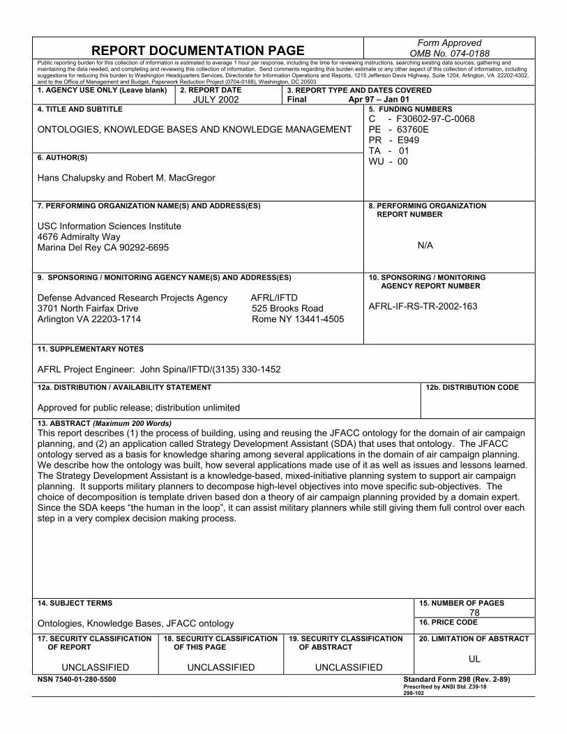
REPORT DOCUMENTATION PAGE Form Approved OMB No. 074-0188
Public reporting burden for this collection of information is estimated to average 1 hour per response, including the time for reviewing instructions, searching existing data sources, gathering and maintaining the data needed, and completing and reviewing this collection of information. Send comments regarding this burden estimate or any other aspect of this collection of information, including suggestions for reducing this burden to Washington Headquarters Services, Directorate for Information Operations and Reports, 1215 Jefferson Davis Highway, Suite 1204, Arlington, VA 22202-4302, and to the Office of Management and Budget, Paperwork Reduction Project (0704-0188), Washington, DC 20503 1. AGENCY USE ONLY (Leave blank)
2. REPORT DATE JULY 2002
3. REPORT TYPE AND DATES COVERED Final Apr 97 – Jan 01
4. TITLE AND SUBTITLE ONTOLOGIES, KNOWLEDGE BASES AND KNOWLEDGE MANAGEMENT
6. AUTHOR(S) Hans Chalupsky and Robert M. MacGregor
5. FUNDING NUMBERS C - F30602-97-C-0068 PE - 63760E PR - E949 TA - 01 WU - 00
7. PERFORMING ORGANIZATION NAME(S) AND ADDRESS(ES) USC Information Sciences Institute 4676 Admiralty Way Marina Del Rey CA 90292-6695
8. PERFORMING ORGANIZATION REPORT NUMBER N/A
9. SPONSORING / MONITORING AGENCY NAME(S) AND ADDRESS(ES) Defense Advanced Research Projects Agency AFRL/IFTD 3701 North Fairfax Drive 525 Brooks Road Arlington VA 22203-1714 Rome NY 13441-4505
10. SPONSORING / MONITORING AGENCY REPORT NUMBER AFRL-IF-RS-TR-2002-163
11. SUPPLEMENTARY NOTES AFRL Project Engineer: John Spina/IFTD/(3135) 330-1452
12a. DISTRIBUTION / AVAILABILITY STATEMENT Approved for public release; distribution unlimited
12b. DISTRIBUTION CODE
13. ABSTRACT (Maximum 200 Words) This report describes (1) the process of building, using and reusing the JFACC ontology for the domain of air campaign planning, and (2) an application called Strategy Development Assistant (SDA) that uses that ontology. The JFACC ontology served as a basis for knowledge sharing among several applications in the domain of air campaign planning. We describe how the ontology was built, how several applications made use of it as well as issues and lessons learned. The Strategy Development Assistant is a knowledge-based, mixed-initiative planning system to support air campaign planning. It supports military planners to decompose high-level objectives into move specific sub-objectives. The choice of decomposition is template driven based don a theory of air campaign planning provided by a domain expert. Since the SDA keeps “the human in the loop”, it can assist military planners while still giving them full control over each step in a very complex decision making process.
15. NUMBER OF PAGES78
14. SUBJECT TERMS Ontologies, Knowledge Bases, JFACC ontology 16. PRICE CODE
17. SECURITY CLASSIFICATION OF REPORT
UNCLASSIFIED
18. SECURITY CLASSIFICATION OF THIS PAGE
UNCLASSIFIED
19. SECURITY CLASSIFICATION OF ABSTRACT
UNCLASSIFIED
20. LIMITATION OF ABSTRACT
UL
NSN 7540-01-280-5500 Standard Form 298 (Rev. 2-89) Prescribed by ANSI Std. Z39-18 298-102
Contents
1 Introduction 1
2 Building, Using and Reusing the JFACC Air Campaign Planning Ontology 4
2.1 Overview . . . . . . . . . . . . . . . . . . . . . . . . . . . . . . . . . . . . . 4
2.2 Developing Applications for the Air Campaign Planning Domain . . . . . . . . 8
2.3 Building the JFACC Ontology . . . . . . . . . . . . . . . . . . . . . . . . . . 12
2.3.1 Integrating application knowledge bases . . . . . . . . . . . . . . . . . 13
2.3.2 Re-using an ontology of time . . . . . . . . . . . . . . . . . . . . . . . 14
2.3.3 Merging two ontologies of aircraft . . . . . . . . . . . . . . . . . . . . 20
2.4 Organization of the JFACC Ontology . . . . . . . . . . . . . . . . . . . . . . . 28
2.4.1 The structure of the JFACC ontology . . . . . . . . . . . . . . . . . . 30
2.5 Using the JFACC ontology . . . . . . . . . . . . . . . . . . . . . . . . . . . . 32
2.6 Conclusions . . . . . . . . . . . . . . . . . . . . . . . . . . . . . . . . . . . . 40
3 The Strategy Development Assistant (SDA) 42
3.1 Overview . . . . . . . . . . . . . . . . . . . . . . . . . . . . . . . . . . . . . 42
3.2 Principles of Design . . . . . . . . . . . . . . . . . . . . . . . . . . . . . . . . 45
i
3.2.1 Rationale . . . . . . . . . . . . . . . . . . . . . . . . . . . . . . . . . 46
3.3 Particular Challenges . . . . . . . . . . . . . . . . . . . . . . . . . . . . . . . 47
3.3.1 Displaying the Recommendation . . . . . . . . . . . . . . . . . . . . . 47
3.3.2 Indicating Control . . . . . . . . . . . . . . . . . . . . . . . . . . . . 48
3.3.3 Linking Controls . . . . . . . . . . . . . . . . . . . . . . . . . . . . . 50
3.4 Conclusions . . . . . . . . . . . . . . . . . . . . . . . . . . . . . . . . . . . . 51
3.5 An Annotated Demo . . . . . . . . . . . . . . . . . . . . . . . . . . . . . . . 51
ii
List of Figures
2.1 Using and reusing ontologies in the construction and employment of the JFACC
Ontology. . . . . . . . . . . . . . . . . . . . . . . . . . . . . . . . . . . . . . 8
2.2 The Ontosaurus ontology browser. Ontosaurus is a graphical Web-based browser
for Loom and PowerLoom knowledge bases. Ontosaurus allows viewing and
interacting with a live Loom knowledge base using the standard HTTP pro-
tocol. Different views and a query-by-example system are supported by the
software. This example shows a side-by-side view of the difference between
an instance representation of “F-16” and a concept representation. . . . . . . . 10
2.3 INSPECT’s agenda of problems found in the plan. INSPECT uses a library of
common errors and problems to examine a user’s plan to see if it contains any
of the errors specified in the library, and then produces an agenda reporting the
problems found. INSPECT has found errors in every air campaign plan it has
examined. . . . . . . . . . . . . . . . . . . . . . . . . . . . . . . . . . . . . . 11
2.4 The Mastermind Objectives Editor. Each objective consists of a main verb
(such as “deploy”) and a number of slots that specify the objects involved in
the action and the location and time of the action. The editor is based on
adaptive forms, a generic editor framework that takes a grammar at run-time
and produces an editing window which is aware of the syntax and provides
directed support to produce admissible sentences in this grammar. . . . . . . . 12
iii
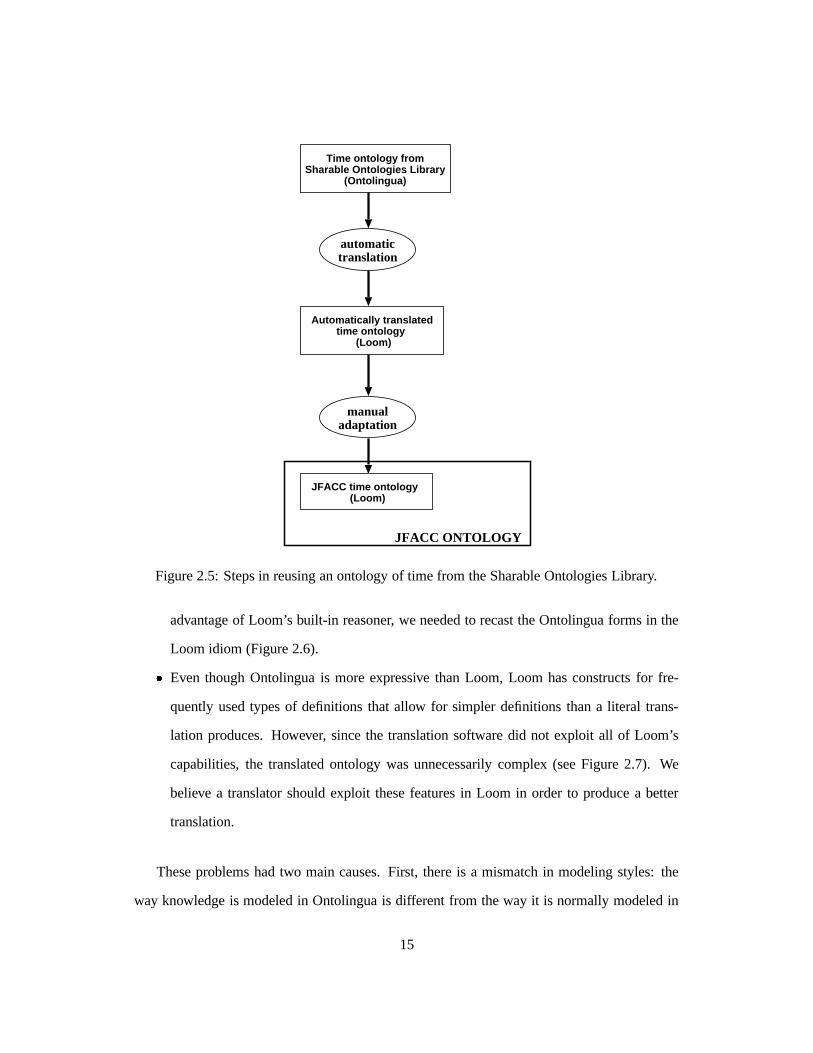
2.5 Steps in reusing an ontology of time from the Sharable Ontologies Library. . . 15
2.6 Definitions of meets in the ontology translated from Loom and the modi-
fied version used in the JFACC Ontology. Notice how the contents of the
related-axioms annotation on the definition produced by the translator
(left) is almost the same as the contents of the :satisfies clause in the
“loomified” definition (right). The expression starting with ����� can be rep-
resented in Loom, since it defines when the relation meets holds between two
time ranges, but in order for Loom to reason with the expression, it must be
part of the definition of the concept (:is clause). . . . . . . . . . . . . . . . . 16
2.7 Definition of day-number in the ontology translated from Ontolingua (right)
and the modified version used in the JFACC Ontology (left). The definition of
day-number in the ontology translated from Ontolingua is made by using
the relations i-upper-bound and i-lower-bound, which relate to the
upper and lower bounds of an integer interval. In contrast, the “loomified”
definition (on the right) uses the built-in operator :through to say the same
thing and allow the Loom inference engine to efficiently reason about day num-
bers. The resulting definition is much simpler, and also allowed us to dispense
with lengthy definitions for types of intervals and relations and axioms about
them. . . . . . . . . . . . . . . . . . . . . . . . . . . . . . . . . . . . . . . . 17
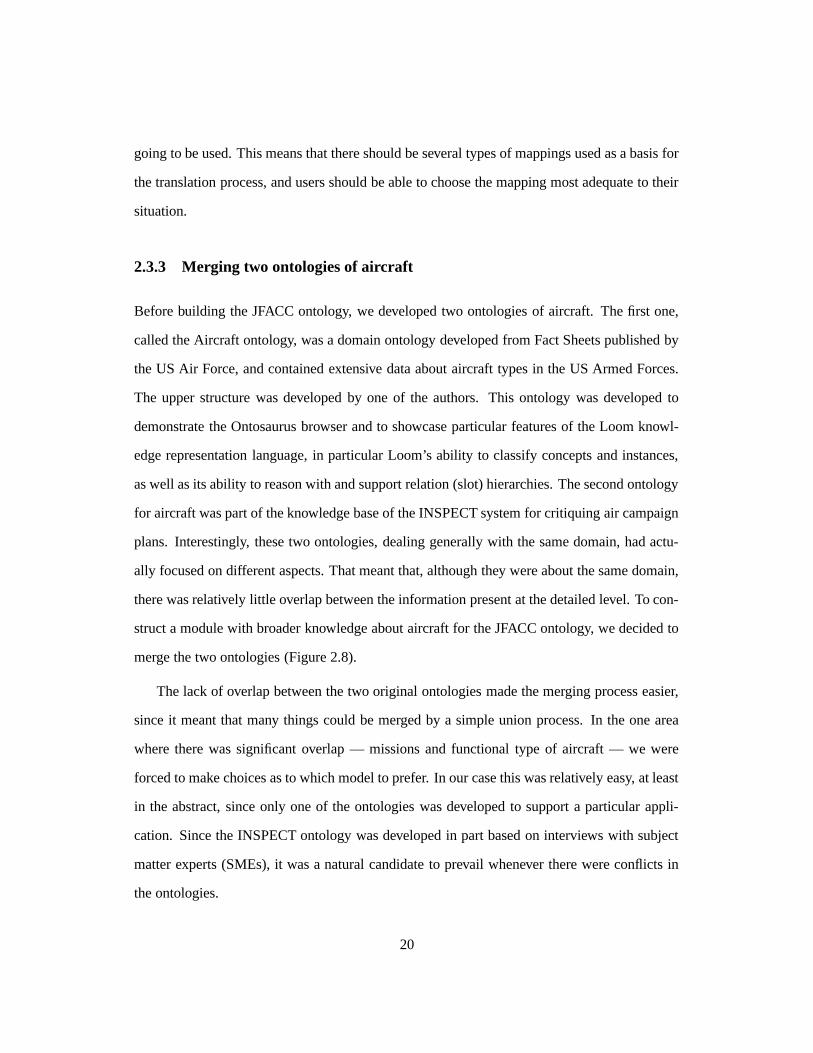
2.8 Merging two knowledge bases into a JFACC aircraft ontology. Two closely
related ontologies focusing on different details were merged to create a more
comprehensive domain model. . . . . . . . . . . . . . . . . . . . . . . . . . . 21
2.9 F-16 Hierarchy in the Aircraft Ontology. . . . . . . . . . . . . . . . . . . . . . 22
2.10 F-16 Hierarchy in the Initial INSPECT Ontology. . . . . . . . . . . . . . . . . 23
2.11 F-16 Hierarchy in the JFACC Ontology. . . . . . . . . . . . . . . . . . . . . . 24
2.12 Organization of the JFACC Ontology into its constituent modules. . . . . . . . 30
iv
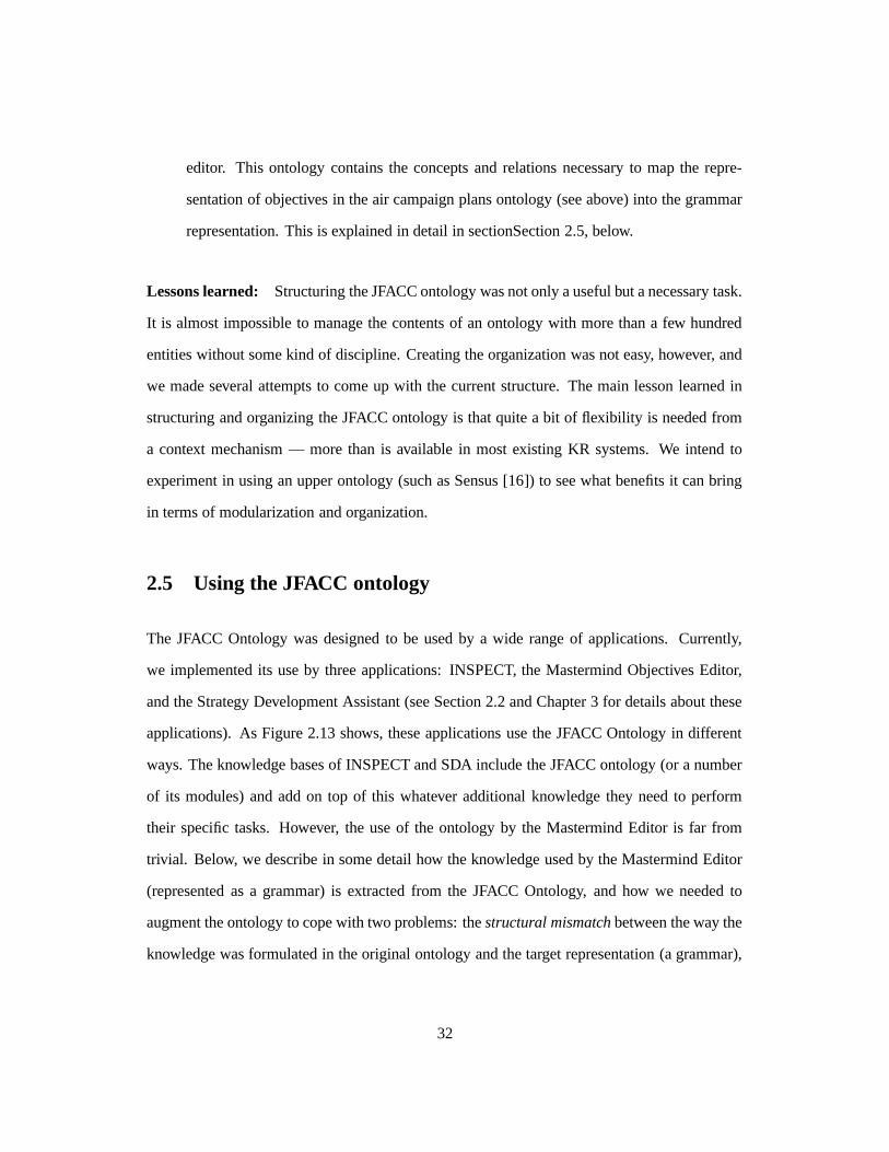
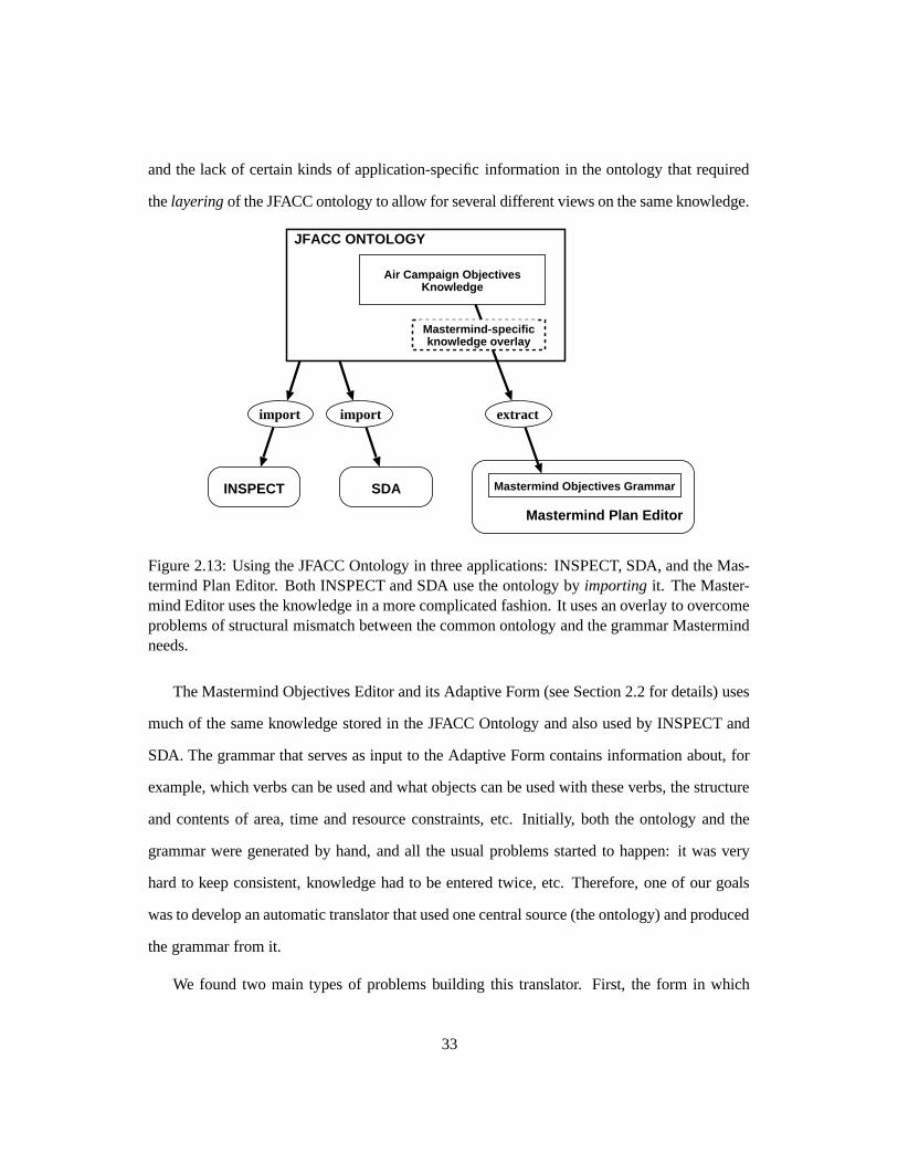
2.13 Using the JFACC Ontology in three applications: INSPECT, SDA, and the
Mastermind Plan Editor. Both INSPECT and SDA use the ontology by im-
porting it. The Mastermind Editor uses the knowledge in a more complicated
fashion. It uses an overlay to overcome problems of structural mismatch be-
tween the common ontology and the grammar Mastermind needs. . . . . . . . 33
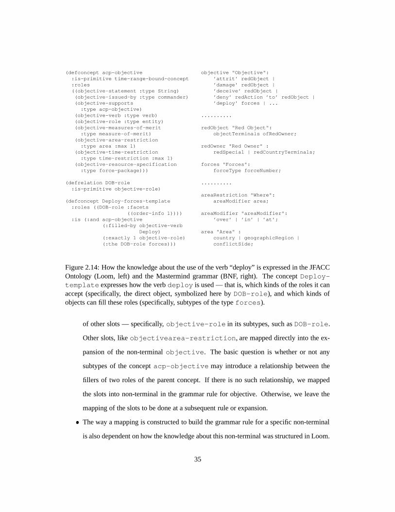
2.14 How the knowledge about the use of the verb “deploy” is expressed in the
JFACC Ontology (Loom, left) and the Mastermind grammar (BNF, right). The
concept Deploy-template expresses how the verb deploy is used —
that is, which kinds of the roles it can accept (specifically, the direct object,
symbolized here by DOB-role), and which kinds of objects can fill these
roles (specifically, subtypes of the type forces). . . . . . . . . . . . . . . . . 35
2.15 Annotation of the concept Deploy-objective-template. . . . . . . . . 38
3.1 SDA Software Architecture . . . . . . . . . . . . . . . . . . . . . . . . . . . . 44
3.2 SDA Editor Interface . . . . . . . . . . . . . . . . . . . . . . . . . . . . . . . 46
3.3 Mockup indicating control with a drawbridge . . . . . . . . . . . . . . . . . . 49
3.4 Mockup indicating control with menus . . . . . . . . . . . . . . . . . . . . . . 49
3.5 Adding a subobjective to the option under the CJTF objective “Gain and Main-
tain Air Superiority” in the objectives editor. . . . . . . . . . . . . . . . . . . . 52
3.6 Step 1 in fleshing out the objective in the Mastermind Plan Editor. . . . . . . . 53
3.7 Step 2 in fleshing out the objective in the Mastermind Plan Editor. . . . . . . . 54
3.8 Step 3 in fleshing out the objective in the Mastermind Plan Editor. . . . . . . . 55
3.9 Step 4 in fleshing out the objective in the Mastermind Plan Editor. . . . . . . . 56
3.10 Step 5 in fleshing out the objective in the Mastermind Plan Editor. . . . . . . . 57
3.11 Final step in fleshing out the objective in the Mastermind Plan Editor. . . . . . 58
v
3.12 The new objective displayed in the Mastermind Plan Editor. . . . . . . . . . . 59
3.13 Selecting an objective in the Mastermind Plan Editor to be decomposed by the
Strategy Development Assistant (SDA). . . . . . . . . . . . . . . . . . . . . . 60
3.14 Sub-objectives of “Protect Sea Lines of Communication” decomposed by the
Strategy Development Assistant (SDA). . . . . . . . . . . . . . . . . . . . . . 61
3.15 Changing one of the assumptions in the Strategy Development Assistant (SDA). 62
3.16 Updating the plan according to the new assumptions in the SDA. . . . . . . . . 63
3.17 The new objective has been added in the Mastermind Plan Editor. . . . . . . . 64
3.18 The INSPECT plan critiquer has determined that there is a special fuel need. . . 65
3.19 End of demo. . . . . . . . . . . . . . . . . . . . . . . . . . . . . . . . . . . . 66
vi
1
Chapter 1 Introduction For any software system, the specifications that developers write to formally describe the behavior
of system components and the protocols they invent to specify how software components will
inter-communicate implicitly define vocabularies for the particular domains addressed by the
system components. For large-scale systems, such as Joint Forces Air Component Commander
(JFACC) After Next, arise when the development of these vocabularies is not coordinated. In the
absence of such coordination, as the scale of the system increases, smooth interoperation of
components becomes increasingly problematic. Humans will find it increasingly difficult to
familiarize themselves with the domain models manipulated by the system, and implementers may
independently invent overlapping (i.e., partially redundant) and/or inconsistent domain models.
A solution to this problem is to construct a collection of formally-specified vocabularies
that define the preferred usage and meaning of terms referenced by each system component. We
call a formal specification of a set of domain terms an ontology. Such ontologies capture (make
explicit) the vocabulary used by system implementers and users. Ontologies need to be aligned so
that their vocabularies do not conflict, and they need to be extensible so that they can grow as the
system grows. The ontologies comprise a living document of the system terminology.
2
A primary objective of the JFACC Program was to semi-automate the process of
constructing computer models that represent military objectives, planned courses of action, etc. As
part of our participation in the JFACC program we developed ontologies for JFACC that provide
rigorously defined conceptual building blocks for these models, and knowledge bases that capture
the semantics of real world entities referenced in a model. The ontologies facilitate unambiguous
communication among cooperating model-builders (both human and software-based), while the
domain knowledge expedites construction of software that can validate, critique, and guide the
model-building process. We also developed an application called the Strategy Development
Assistant (SDA) that leverages the developed ontologies and knowledge bases.
A primary contribution of our group is the JFACC ontology that was shared and used by a
variety of contractors of the JFACC program. We analyzed the ontologies already developed
within the ARPA Rome Planning Initiative (ARPI) and integrated them into a common ontology
for ARPI and JFACC. The JFACC ontology draws from the ACP-SENSUS ontology, the
INSPECT Air Campaign Objectives ontology and domain model (developed at ISI for critiquing
air campaign plans), as well as ARPI planning and scheduling ontologies and PIF process ontology
(supported in part by ARPA Knowledge Sharing Effort). A second result of our effort is the
JFACC knowledge base containing knowledge about air campaign planning processes, planning
factors, available assets and their capabilities, generic tasks, strategies, and objectives.
During the life of the program, the JFACC ontologies and knowledge bases were managed
by an Ontology Server where they could be accessed by other program participants. This
component was based on ISI’s Loom knowledge representation system (Loom is an advanced KRS
developed at ISI under DARPA sponsorship that has been distributed to corporations and
universities world-wide). Today, the JFACC ontology is still browsable on-line at
http://www.isi.edu/isd/ontosaurus.html (select the “live demonstration version”, follow the
instructions to connect to the Ontosaurus browser and select theory “INSPECT”).
Another result of our efforts was the Strategy Development Assistant or SDA. It is a
knowledge-based system for aiding Air Campaign Planning and it leverages the JFACC knowl-
edge base also developed by us. An early part of the planning process involves the decomposi-
tion of high level objectives into more specific sub-objectives. The SDA assists the user in this
decomposition process by providing suggested decompositions based on the current situation
and high-level goals.
The SDA is used to support military planners in an early phase of air campaign planning.
The choice of decompositions is template-driven, based on a set of underlying assumptions.
The SDA’s graphical user interface details the assumptions, allows the user to modify the values
of the assumptions and, thus, captures the assumptions underlying the plan. The SDA is a truly
mixed-initiative planning system. All elements of the interface design are geared towards
giving the user total control of the decisions taken in the decomposition process.
The rest of this report is structured as follows: In Chapter 2 we describe the building
process of the JFACC ontology, in particular, the problems encountered and lessons learned
while merging overlapping ontologies as well as developing an ontology that was to be used
by multiple independetly developed systems. In Chapter 3 we describe the Strategy Develop-
ment Assistant and show an annotated integrated demo show-casing the SDA as well as other
components developed by JFACC contractors here at ISI.
3
Chapter 2
Building, Using and Reusing the
JFACC Air Campaign Planning
Ontology
2.1 Overview
Military air campaign planners develop plans for using aircraft to achieve a variety of objec-
tives. For a number of reasons, air campaign planning is a very complex process. First, there
are a number of interacting planning concerns. In addition to figuring out how aircraft will be
used, one must also create a plan for supporting the aircraft by supplying the necessary fuel,
spare parts, munitions and so forth. Today, these different planning processes proceed in a
fairly independent fashion, leading to serious problems when conflicts are discovered. Second,
the kinds of operations in which the military may become involved are now much broader.
Whereas once the military planned for large-scale battles with major opponents, now in addi-
tion to traditional military tasks, the armed forces must be prepared to deal with a wide variety
of tasks that do not involve the application of force, such as non-combatant evacuations or hu-
4
manitarian relief operations. Third, the nature of air campaign planning itself has changed and
become more deliberate with the development of the “strategies-to-task” approach. Previously,
air campaign planning was primarily bottom-up, focusing on military targets and planning op-
erations to attack them. This approach is clearly less appropriate for non-military operations,
but even for military operations a problem was that the rationale behind the plan was often
lost, so it was not clear what objectives were being served by attacking a particular target.
In the strategies-to-task planning approach, high level objectives (such as “provide relief to
refugees in the southern region of country A”) are decomposed into increasingly more specific
objectives until one has planned specific tasks for particular aircraft.
Starting with the ARPA Rome Planning Initiative (ARPI) program, and continuing during
DARPA’s Joint Forces Air Component Commander (JFACC) program, we researched and de-
veloped a number of knowledge-based applications for the domain of air campaign planning.
Withing the JFACC program, we have used this experience to build a relatively broad ontology
of air campaign planning, called the JFACC ontology. In developing this ontology, we had
several goals:
1. Facilitate inter-operation and communication between systems by providing a common
terminology. This was important because the JFACC software was being developed by
several different groups.
2. Promote sharing of knowledge between systems. In particular, we wanted to integrate
our knowledge acquisition and modeling efforts. Even within ISI different groups were
developing related knowledge bases and ontologies for their own applications. These
ontologies were all in the same domain, frequently with a high degree of commonality,
but also sometimes with marked modeling differences that stem from different degrees
of access to experts, documentation, etc.
3. Create a repository for general knowledge about air campaign planning that could be
5
used across the broader research program in several applications, including traditional
ones (that is, not knowledge-based).
The development of the ontology is to a large extent a function of the needs of the appli-
cations that make use of it, and as such we have been often pragmatic in deciding which area
to attack first. For instance, it has representations for many of the basic concepts one would
expect (time, objectives, plans), but other concepts (such as action and space) are represented
in a somewhat simplified (and pragmatic) manner, since it was not yet necessary to use a more
complete and principled representation of these kinds of knowledge. The final version of the
ontology has about 1,750 entities (about 1,100 concepts, 400 relations and 250 instances).
In the following, we relate the experience and the lessons learned in building the JFACC
ontology and re-using it in several applications. We used existing knowledge bases from our
applications, general ontologies of domain elements such as airplanes, as well as existing on-
tologies available from public repositories. We divided the contents of the ontology into several
modules, so as to make it more easily reusable when the entire ontology is not required. The
resulting combined ontology was used in several applications, sometimes requiring translation
or adaptation.
Several papers in the literature [6, 7, 18] discuss the use of ontologies to enable reuse and
as a tool to provide a more rational development of knowledge-based systems. In using and
reusing ontologies, several operations and manipulations take place, such as translating on-
tologies described in one formalism to another, merging two or more ontologies into a new
ontology, or structuring large ontologies into manageable parts. While we agree these opera-
tions are necessary and useful, most of the literature discusses these issues from a theoretical
perspective, and the ontologies produced are seldom used by applications. What we found
in our experience is that developing a large ontology that actually needs to be used by more
than one application is a very painful process, and that many of the techniques proposed in
the literature do not work as easily in practice as we would like. In this report we provide a
6
“report from the trenches” and discuss what issues are relevant when trying to obtain usability
and reusability in real applications. We will discuss what problems were found in building
and using the JFACC ontology, how these problems were solved, and what issues arose in the
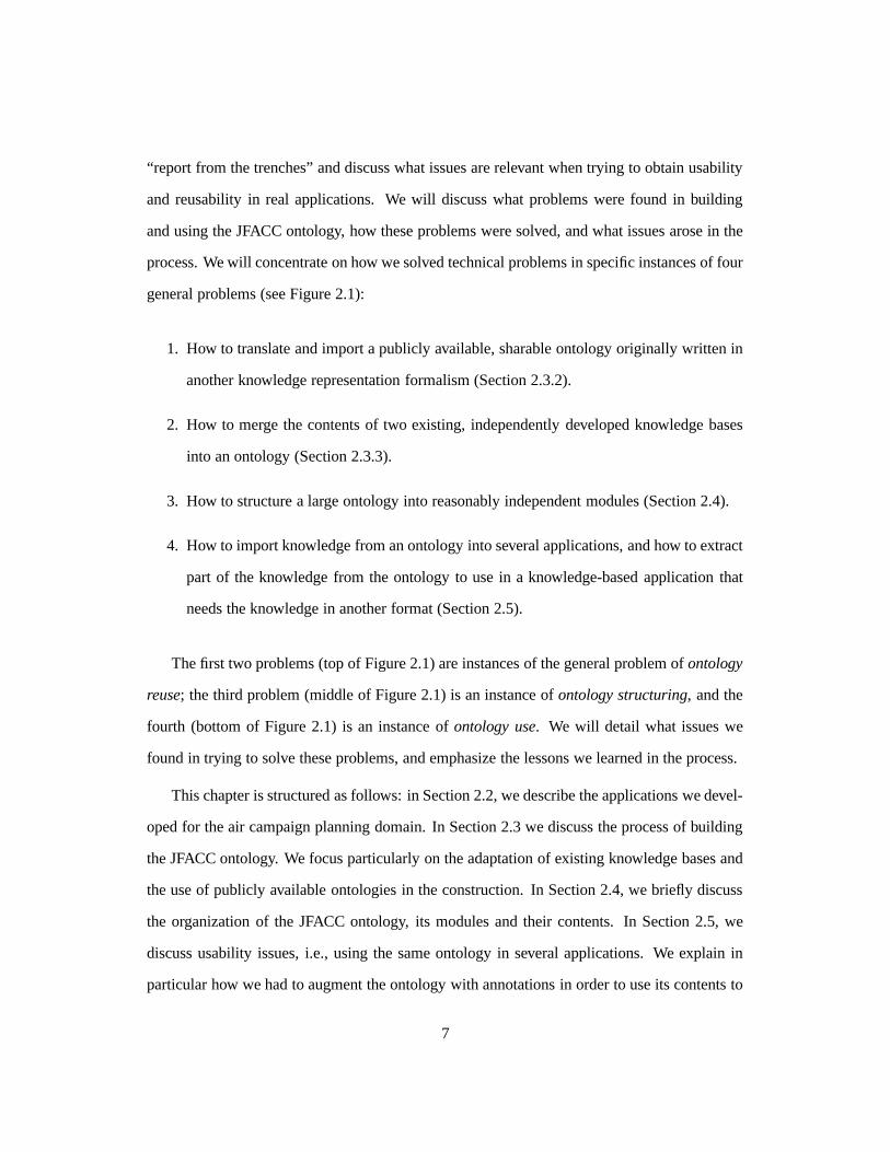
process. We will concentrate on how we solved technical problems in specific instances of four
general problems (see Figure 2.1):
1. How to translate and import a publicly available, sharable ontology originally written in
another knowledge representation formalism (Section 2.3.2).
2. How to merge the contents of two existing, independently developed knowledge bases
into an ontology (Section 2.3.3).
3. How to structure a large ontology into reasonably independent modules (Section 2.4).
4. How to import knowledge from an ontology into several applications, and how to extract
part of the knowledge from the ontology to use in a knowledge-based application that
needs the knowledge in another format (Section 2.5).
The first two problems (top of Figure 2.1) are instances of the general problem of ontology
reuse; the third problem (middle of Figure 2.1) is an instance of ontology structuring, and the
fourth (bottom of Figure 2.1) is an instance of ontology use. We will detail what issues we
found in trying to solve these problems, and emphasize the lessons we learned in the process.
This chapter is structured as follows: in Section 2.2, we describe the applications we devel-
oped for the air campaign planning domain. In Section 2.3 we discuss the process of building
the JFACC ontology. We focus particularly on the adaptation of existing knowledge bases and
the use of publicly available ontologies in the construction. In Section 2.4, we briefly discuss
the organization of the JFACC ontology, its modules and their contents. In Section 2.5, we
discuss usability issues, i.e., using the same ontology in several applications. We explain in
particular how we had to augment the ontology with annotations in order to use its contents to
7
ApplicationKB
DomainKB
Publiclyavailableontology
Knowledge-based
application
Knowledge-based
application
translate merge
import extract
JFACCONTOLOGY
OntologyReuse
OntologyUse
OntologyStructuring
Figure 2.1: Using and reusing ontologies in the construction and employment of the JFACCOntology.
build a grammar that used the same knowledge in the ontology. In Section 2.6 we present our
conclusions.
2.2 Developing Applications for the Air Campaign Planning Do-
main
Within ISI several groups developed applications for the domain of air campaign planning
during the course of the JFACC program. We (the Loom group) focused on the development
8
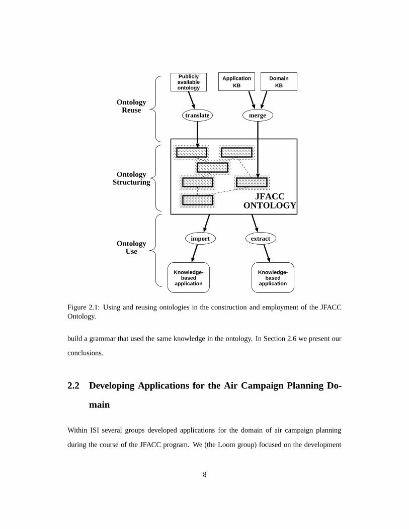
of various ontologies for JFACC as well as building and extending general purpose tools for
ontology construction such as Ontosaurus [16] (see Figure 2.2 for a sample screen). These
tools leverage the Loom and PowerLoom knowledge representation systems also developed by
us [11]. Additionally, we developed the Strategy Development Assistant (SDA). The SDA is
a mixed-initiative tool to help planners decompose their objectives into sub-objectives. SDA
provides support for intelligent, guided plan development, following a theory of air campaign
plan decomposition based on the strategies-to-task approach. SDA is built on top of Loom,
making extensive use of Loom’s representation and reasoning facilities. It is described in more
detail in Chapter 3.
The JFACC Ontology is represented in Loom [10]. Loom is a knowledge representation
framework based on description logics [15]. Like other description logics, Loom is based on
a semantic network approach to knowledge representation. It is possible to define concepts in
Loom. Concepts can have roles or slots which may be used to specify attributes of the concept.
A key feature of description logic representations is that the semantics of the representation
language is very precisely specified. This precise specification makes it possible to build a tool,
called a classifier [11], that can determine whether or not one concept subsumes another based
solely on the formal definitions of the two concepts.1 The classifier is an important tool for
building ontologies because it can be used to organize a set of Loom concepts into a hierarchy
automatically, based solely on their definitions. This capability is particularly important as the
ontology becomes large, since the classifier will find subsumption relations that people might
overlook, as well as modeling errors that could make the knowledge base inconsistent.
Other groups at ISI developing JFACC applications were the EXPECT and Mastermind
groups. The EXPECT group, headed by Yolanda Gil, developed a plan evaluation tool called
INSPECT [17]. INSPECT is designed to critique air campaign plans that people have entered
1A concept A is said to subsume a concept B if all the possible entities that could be described by B are alsonecessarily described by A. For example, “a man who only drinks beer” subsumes “a man who only drinks importedbeer.” More details about subsumption can be found in [19]
9
Figure 2.2: The Ontosaurus ontology browser. Ontosaurus is a graphical Web-based browserfor Loom and PowerLoom knowledge bases. Ontosaurus allows viewing and interacting witha live Loom knowledge base using the standard HTTP protocol. Different views and a query-by-example system are supported by the software. This example shows a side-by-side view ofthe difference between an instance representation of “F-16” and a concept representation.
10
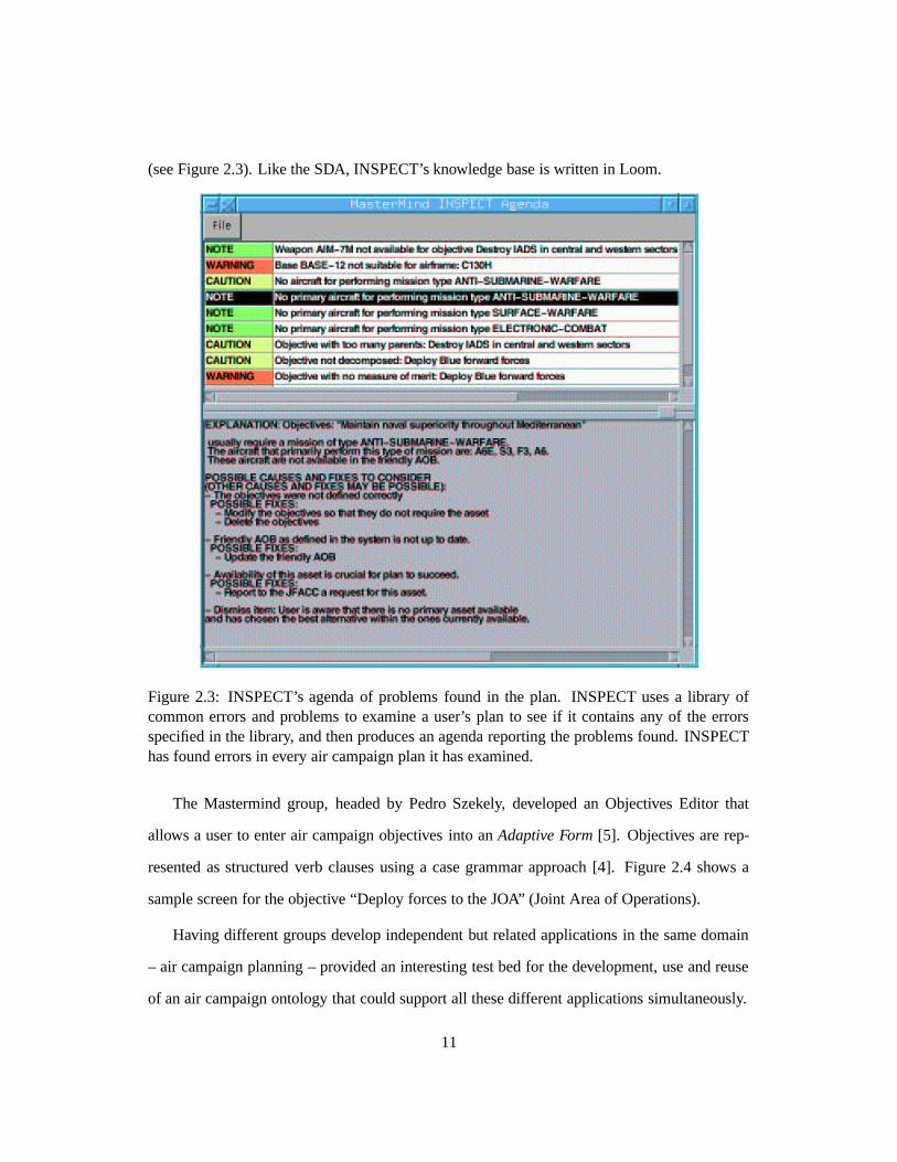
(see Figure 2.3). Like the SDA, INSPECT’s knowledge base is written in Loom.
Figure 2.3: INSPECT’s agenda of problems found in the plan. INSPECT uses a library ofcommon errors and problems to examine a user’s plan to see if it contains any of the errorsspecified in the library, and then produces an agenda reporting the problems found. INSPECThas found errors in every air campaign plan it has examined.
The Mastermind group, headed by Pedro Szekely, developed an Objectives Editor that
allows a user to enter air campaign objectives into an Adaptive Form [5]. Objectives are rep-
resented as structured verb clauses using a case grammar approach [4]. Figure 2.4 shows a
sample screen for the objective “Deploy forces to the JOA” (Joint Area of Operations).
Having different groups develop independent but related applications in the same domain
– air campaign planning – provided an interesting test bed for the development, use and reuse
of an air campaign ontology that could support all these different applications simultaneously.
11
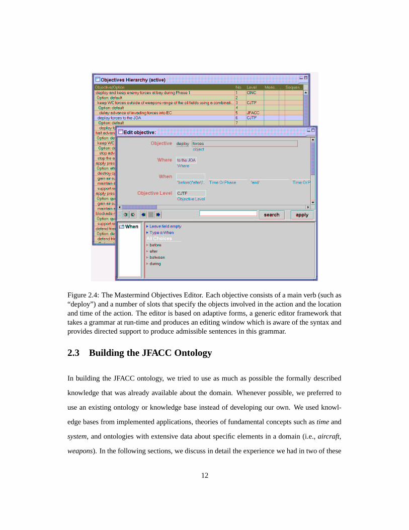
Figure 2.4: The Mastermind Objectives Editor. Each objective consists of a main verb (such as“deploy”) and a number of slots that specify the objects involved in the action and the locationand time of the action. The editor is based on adaptive forms, a generic editor framework thattakes a grammar at run-time and produces an editing window which is aware of the syntax andprovides directed support to produce admissible sentences in this grammar.
2.3 Building the JFACC Ontology
In building the JFACC ontology, we tried to use as much as possible the formally described
knowledge that was already available about the domain. Whenever possible, we preferred to
use an existing ontology or knowledge base instead of developing our own. We used knowl-
edge bases from implemented applications, theories of fundamental concepts such as time and
system, and ontologies with extensive data about specific elements in a domain (i.e., aircraft,
weapons). In the following sections, we discuss in detail the experience we had in two of these
12
reuse processes. First, we discuss how we imported an existing and publicly available ontol-
ogy of time into the JFACC ontology. Second, we discuss how we merged two ontologies of
aircraft that had been developed for different uses into a common shared ontology.
2.3.1 Integrating application knowledge bases
A large part of the material in the JFACC Ontology came from the knowledge base of the
INSPECT system [17]. This knowledge base included detailed representations for all the main
elements of air campaign plans: campaigns, objectives, missions, phases, areas, sequencing,
etc. It also included an extensive typology of military targets, from military headquarters to
petroleum production facilities. Finally, it included basic representations for resources such as
aircraft and weapons.
One of the important characteristics of the INSPECT knowledge base is that it was not par-
ticularly “deep” or principled. Most of the hierarchies were only a few levels deep, and in many
cases possible subsumption links were left unexplored. For example, despite the fact that most
of the typology of targets dealt with physical objects, there was no such concept in the knowl-
edge base, the reason being that the concept of object was enough (no significant non-physical
objects were relevant). Also, concepts such as time and area had very simple representations,
just about enough to do the reasoning necessary for the application’s purpose. The emphasis
was on producing highly structured concepts, with a rich web of interrelations, that was useful
for representing the air campaign plan and reasoning about its parts. All these characteristics
were to a large extent a consequence of the teleological nature of the knowledge base: despite
some effort to make the definitions clear and organized, the knowledge it contained was meant
to be just enough to produce certain types of inferences. In other words, usability was far more
important that reusability.
In the process of making the material in the INSPECT knowledge base more reusable, we
decided that we needed ontologies to represent in a more principled way some of the most fun-
13
damental elements of the domain. We started by incorporating ontology of time and systems.
2.3.2 Re-using an ontology of time
Time is an essential constituent of the air campaign domain. We wanted a complete and well-
founded ontology of time, but wanted to avoid the time-consuming formalization and repre-
sentation process. We therefore looked for a pre-built and publicly available ontology.
After some search, we found a satisfactory ontology of time (based on Allen’s theory of
time [1]) in the Sharable Ontologies Library at Stanford.2 It was part of a job assignment ontol-
ogy developed by [8]. In trying to reuse this ontology for JFACC, we found several problems,
all of them loosely connected to the fact that we had to use an Ontolingua translator to im-
port the original ontology (written in Ontolingua) into our targets knowledge representation
language (Loom).3 The Ontolingua translator was useful for producing a first draft of a Loom
ontology, but the resulting translation had several problems. Therefore, we had to make an ex-
tensive manual adaptation of the translated ontology. The overall process of reuse is described
in Figure 2.5.
The problems with the translated ontology from Ontolingua were:
� The ontology that resulted from the translation process was dependent on a general KIF
theory for frames (the frame ontology). This is a consequence of the fact that Ontolingua
itself is based on the frame ontology, that is, the Ontolingua constructs for frames are
built on top of the basic elements of KIF. One easy solution for this problem would
have been to import this theory into our knowledge base as well, but we chose not to
do that. Many of the frame ontology commitments already existed in Loom, and to take
2URL http://www-ksl.stanford.edu/knowledge-sharing/ontologies/README.html.3For details on Ontolingua and its translators, see the pages on Ontolingua at the Stanford University Knowledge
Systems Laboratory http://ontolingua.stanford.edu/.
14
Time ontology fromSharable Ontologies Library
(Ontolingua)
automatictranslation
JFACC ONTOLOGY
Automatically translatedtime ontology
(Loom)
JFACC time ontology (Loom)
manualadaptation
Figure 2.5: Steps in reusing an ontology of time from the Sharable Ontologies Library.
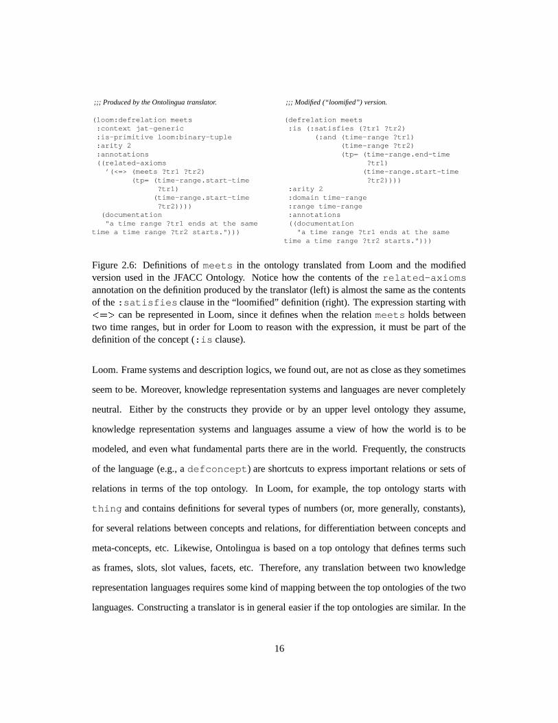
advantage of Loom’s built-in reasoner, we needed to recast the Ontolingua forms in the
Loom idiom (Figure 2.6).
� Even though Ontolingua is more expressive than Loom, Loom has constructs for fre-
quently used types of definitions that allow for simpler definitions than a literal trans-
lation produces. However, since the translation software did not exploit all of Loom’s
capabilities, the translated ontology was unnecessarily complex (see Figure 2.7). We
believe a translator should exploit these features in Loom in order to produce a better
translation.
These problems had two main causes. First, there is a mismatch in modeling styles: the
way knowledge is modeled in Ontolingua is different from the way it is normally modeled in
15
;;; Produced by the Ontolingua translator.
(loom:defrelation meets:context jat-generic:is-primitive loom:binary-tuple:arity 2:annotations((related-axioms
’(<=> (meets ?tr1 ?tr2)(tp= (time-range.start-time
?tr1)(time-range.start-time?tr2))))
(documentation"a time range ?tr1 ends at the same
time a time range ?tr2 starts.")))
;;; Modified (“loomified”) version.
(defrelation meets:is (:satisfies (?tr1 ?tr2)
(:and (time-range ?tr1)(time-range ?tr2)(tp= (time-range.end-time
?tr1)(time-range.start-time?tr2))))
:arity 2:domain time-range:range time-range:annotations((documentation
"a time range ?tr1 ends at the sametime a time range ?tr2 starts.")))
Figure 2.6: Definitions of meets in the ontology translated from Loom and the modifiedversion used in the JFACC Ontology. Notice how the contents of the related-axiomsannotation on the definition produced by the translator (left) is almost the same as the contentsof the :satisfies clause in the “loomified” definition (right). The expression starting with��� � can be represented in Loom, since it defines when the relation meets holds betweentwo time ranges, but in order for Loom to reason with the expression, it must be part of thedefinition of the concept (:is clause).
Loom. Frame systems and description logics, we found out, are not as close as they sometimes
seem to be. Moreover, knowledge representation systems and languages are never completely
neutral. Either by the constructs they provide or by an upper level ontology they assume,
knowledge representation systems and languages assume a view of how the world is to be
modeled, and even what fundamental parts there are in the world. Frequently, the constructs
of the language (e.g., a defconcept) are shortcuts to express important relations or sets of
relations in terms of the top ontology. In Loom, for example, the top ontology starts with
thing and contains definitions for several types of numbers (or, more generally, constants),
for several relations between concepts and relations, for differentiation between concepts and
meta-concepts, etc. Likewise, Ontolingua is based on a top ontology that defines terms such
as frames, slots, slot values, facets, etc. Therefore, any translation between two knowledge
representation languages requires some kind of mapping between the top ontologies of the two
languages. Constructing a translator is in general easier if the top ontologies are similar. In the
16

;;; Produced by the Ontolingua translator.
(loom:defconcept day-number:context jat-generic:is-primitive loom:thing:annotations((related-axioms’(= (i-upper-bound day-number) 31))(related-axioms’(= (i-lower-bound day-number) 1))
(documentation"DAY-NUMBER denotes a day of a
month.")))
;;; Modified (“loomified”) version.
(defconcept day-number:is (:through 1 31):annotations((documentation
"DAY-NUMBER denotes a day of amonth.")))
Figure 2.7: Definition of day-number in the ontology translated from Ontolingua (right)and the modified version used in the JFACC Ontology (left). The definition of day-numberin the ontology translated from Ontolingua is made by using the relations i-upper-boundand i-lower-bound, which relate to the upper and lower bounds of an integer interval.In contrast, the “loomified” definition (on the right) uses the built-in operator :throughto say the same thing and allow the Loom inference engine to efficiently reason about daynumbers. The resulting definition is much simpler, and also allowed us to dispense with lengthydefinitions for types of intervals and relations and axioms about them.
case of Loom and Ontolingua, the similarity is reasonable but not very high, which explains
why producing a good translation is feasible but to produce an excellent one is very difficult.
Second, and more interestingly, there seems to be an inferencing engine bias in modeling.
Even when there is no bias towards tailoring the knowledge to be used by a specific application
or problem solving method, knowledge is usually modeled with certain types of inferences in
mind. For example, if we expect to use the Loom classifier to infer whether or not two intervals
meet (that is, (meets int1 int2), we need to add enough information in the definition of
the relation meets to enable the classifier to use it. If, however, all we want to do is to assert
that the intervals meet and use this information for other inferences, it is enough to state the
range and domain of the meets relation.
In contrast, Ontolingua did not have an implemented reasoner. Consequently, the infer-
encing bias either reflects the use the ontology had originally (if it was produced for specific
application), or tends to approximate some abstract form of theorem proving that is “natural”
when one establishes logical definitions.
17
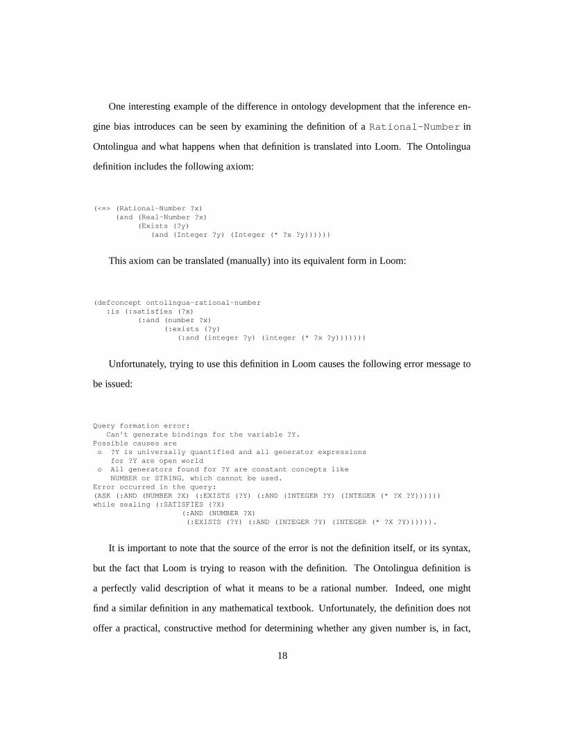
One interesting example of the difference in ontology development that the inference en-
gine bias introduces can be seen by examining the definition of a Rational-Number in
Ontolingua and what happens when that definition is translated into Loom. The Ontolingua
definition includes the following axiom:
(<=> (Rational-Number ?x)(and (Real-Number ?x)
(Exists (?y)(and (Integer ?y) (Integer (* ?x ?y))))))
This axiom can be translated (manually) into its equivalent form in Loom:
(defconcept ontolingua-rational-number:is (:satisfies (?x)
(:and (number ?x)(:exists (?y)
(:and (integer ?y) (integer (* ?x ?y)))))))
Unfortunately, trying to use this definition in Loom causes the following error message to
be issued:
Query formation error:Can’t generate bindings for the variable ?Y.
Possible causes areo ?Y is universally quantified and all generator expressions
for ?Y are open worldo All generators found for ?Y are constant concepts like
NUMBER or STRING, which cannot be used.Error occurred in the query:(ASK (:AND (NUMBER ?X) (:EXISTS (?Y) (:AND (INTEGER ?Y) (INTEGER (* ?X ?Y))))))while sealing (:SATISFIES (?X)
(:AND (NUMBER ?X)(:EXISTS (?Y) (:AND (INTEGER ?Y) (INTEGER (* ?X ?Y)))))).
It is important to note that the source of the error is not the definition itself, or its syntax,
but the fact that Loom is trying to reason with the definition. The Ontolingua definition is
a perfectly valid description of what it means to be a rational number. Indeed, one might
find a similar definition in any mathematical textbook. Unfortunately, the definition does not
offer a practical, constructive method for determining whether any given number is, in fact,
18
a rational number. Consider what the definition tells you: In order to figure out if ?X is a
rational number, one merely needs to find some integer ?Y such that ?X times ?Y yields an
integer. Mechanistically how would a computer program (such as Loom) use this definition?
First, enumerate the integers and test them, stopping when a suitable ?Y was found. While
theoretically sound, this approach suffers from efficiency problems. In fact, Loom recognizes
this and knows enough not to try — thus the error message. In this particular case it is the
second of the two possible causes of the problem that apply.
Lessons Learned: In our work in trying to translate and import a publicly available ontology
of time, we learned that translator technology is still immature. Translation of ontologies
written in different formalisms is generally a difficult task. The Ontolingua-to-Loom translator
is clearly problematic, but in fact creating a better one is by no means easy. We found that the
result of the automatic translation is still interesting as a draft, but lots of human intervention are
required to translate Ontolingua into Loom. This seems to be caused by at least two problems.
First, it is rarely recognized in constructing these translators that they must somehow bridge the
gaps between the underlying models and views used in the formalisms (e.g., mapping frames
and slots into concepts and relations) as well as between the “upper models” assumed in the
development of the ontologies in each formalism (e.g., the frame ontology in Ontolingua and
the representation of numbers in Loom’s built-in-theory. Second, ontologies usually
contain an inferencing bias that makes mapping even more difficult, and importing even more
time-consuming. A large part of the literature on ontologies, particularly on the formal/logical
side, treats an ontology as an end in itself. For system builders, however, ontologies are means
to an end, namely to improve the engineering of knowledge-based systems by allowing reuse.
As a consequence, inferencing bias is a feature, not a bug. The challenge is not to get rid
of this bias, but to create translators that allow to (re)introduce (under the user’s command)
in the translation process. In other words, translators need to take into account not only
the “meaning” of the descriptions or definitions in the ontology, but how these constructs are
19
going to be used. This means that there should be several types of mappings used as a basis for
the translation process, and users should be able to choose the mapping most adequate to their
situation.
2.3.3 Merging two ontologies of aircraft
Before building the JFACC ontology, we developed two ontologies of aircraft. The first one,
called the Aircraft ontology, was a domain ontology developed from Fact Sheets published by
the US Air Force, and contained extensive data about aircraft types in the US Armed Forces.
The upper structure was developed by one of the authors. This ontology was developed to
demonstrate the Ontosaurus browser and to showcase particular features of the Loom knowl-
edge representation language, in particular Loom’s ability to classify concepts and instances,
as well as its ability to reason with and support relation (slot) hierarchies. The second ontology
for aircraft was part of the knowledge base of the INSPECT system for critiquing air campaign
plans. Interestingly, these two ontologies, dealing generally with the same domain, had actu-
ally focused on different aspects. That meant that, although they were about the same domain,
there was relatively little overlap between the information present at the detailed level. To con-
struct a module with broader knowledge about aircraft for the JFACC ontology, we decided to
merge the two ontologies (Figure 2.8).
The lack of overlap between the two original ontologies made the merging process easier,
since it meant that many things could be merged by a simple union process. In the one area
where there was significant overlap — missions and functional type of aircraft — we were
forced to make choices as to which model to prefer. In our case this was relatively easy, at least
in the abstract, since only one of the ontologies was developed to support a particular appli-
cation. Since the INSPECT ontology was developed in part based on interviews with subject
matter experts (SMEs), it was a natural candidate to prevail whenever there were conflicts in
the ontologies.
20
JFACC ONTOLOGY
INSPECTKnowledge Base
(Loom)
JFACC aircraft ontology (Loom)
merging
AIrcraft KBdomain ontology
(Loom)
Figure 2.8: Merging two knowledge bases into a JFACC aircraft ontology. Two closely relatedontologies focusing on different details were merged to create a more comprehensive domainmodel.
In practice, however, the merging proved trickier than one might have expected. That is
because there were substantial structural differences between the two ontologies. One major
example was in the method used to determine whether particular aircraft models were, for
example, fighters or bombers. In the Aircraft ontology, this classification was inferred based
on the missions the aircraft could perform. In INSPECT, the mission were not directly related
to the aircraft types. It turned out that since in the aircraft knowledge base type memberships
were all inferred by Loom’s classifier, switching from one system to the other was easier that it
otherwise might have been. There were no direct type assertions about these type memberships
about individual aircraft in the Aircraft knowledge base, so changing to the INSPECT structure
didn’t require deleting any assertions in the Aircraft ontology.
Although not required by the merging process itself, we did, however, take the opportunity
of doing the merge to reexamine a fundamental question in the models: Should aircraft types
be modeled as concepts or as instances? The general issue of whether to model particular
items in a domain as instances or concepts can be difficult to resolve when a knowledge base
terminates in abstract entities. It also depends on the particular use for which a ontology is
designed. (see for example, [2]). The fact that such usage influences a fundamental modeling
issue is unfortunate from the point of view of making ontologies reusable and easily applied
21
for applications that were not envisioned at the time of the creation of the ontology.
When the items being modeled in the world are “naturally” individuals, this is less of an
issue. For example, if one were creating a ontology describing Air Force aircraft, then having
instances correspond to particular airplanes such as “F-16 serial number 87-0217” there is
relatively little controversy. The issue arises mainly when one wishes to not represent the world
at quite so detailed a level. In that case, one needs to face the choice of whether one wishes to
have particular models (classes) of aircraft represented in the ontology by an instances. One
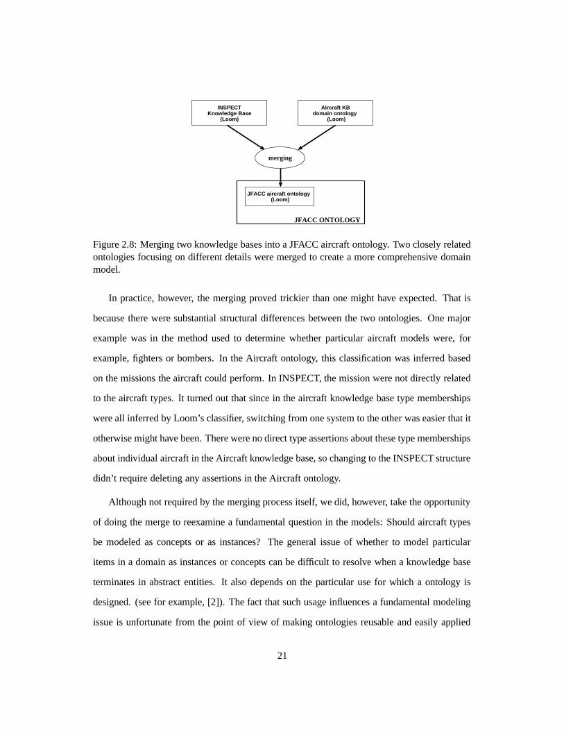
could, for example, model the F-16C as an instance instead of a concept.
This was the approach taken in the Aircraft ontology. This lead to a natural definition of
the instance as having particular fillers for attributes such as crew-size, range, payload, etc. An
example of this hierarchy is shown in Figure 2.9.
Thing
Entity
Physical Entity
Moving-Object
Flying-Object Vehicle
Aircraft
Fixed-Wing-Aircraft Combat-Aircraft
Fighter Bomber
F-16
Fighter-Bomber
Superconcept
Instance
Concept
Superconcept link
Instance oflink
Legend
Figure 2.9: F-16 Hierarchy in the Aircraft Ontology.
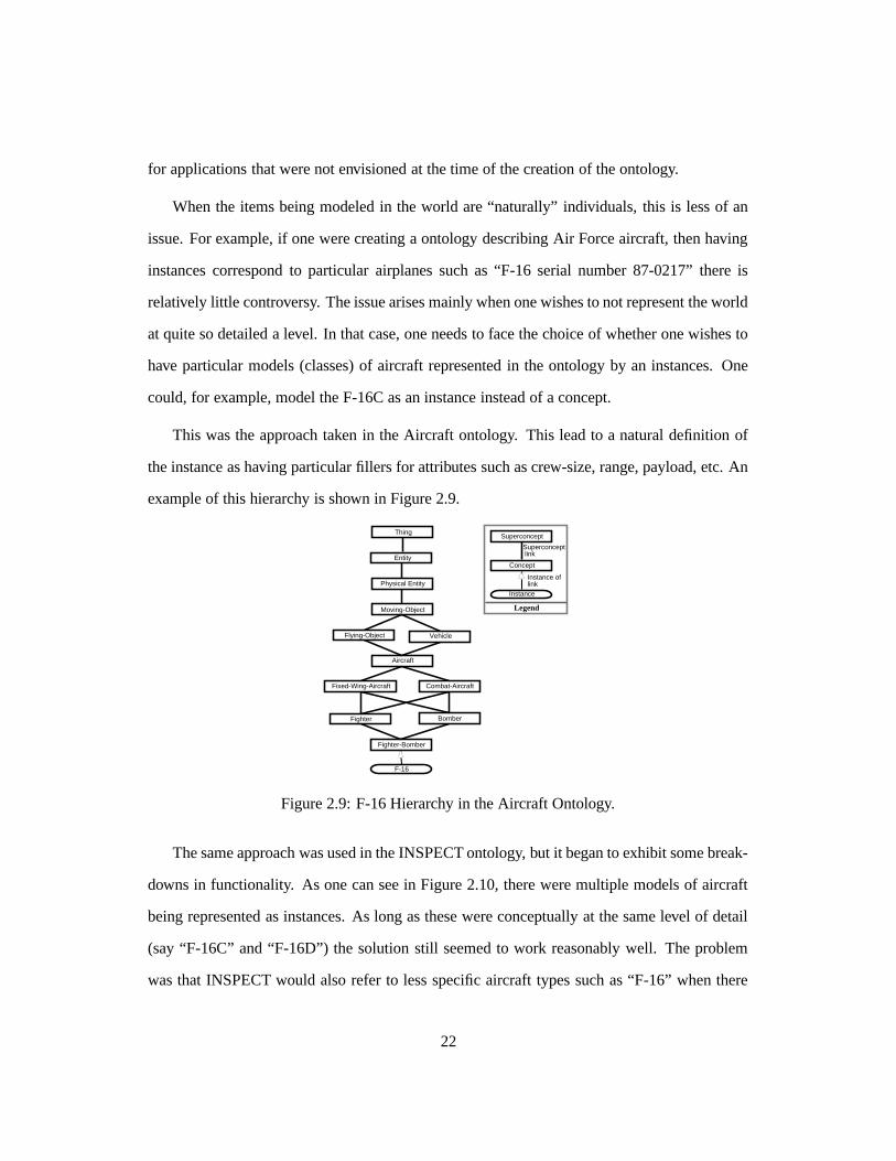
The same approach was used in the INSPECT ontology, but it began to exhibit some break-
downs in functionality. As one can see in Figure 2.10, there were multiple models of aircraft
being represented as instances. As long as these were conceptually at the same level of detail
(say “F-16C” and “F-16D”) the solution still seemed to work reasonably well. The problem
was that INSPECT would also refer to less specific aircraft types such as “F-16” when there
22
wasn’t a need to differentiate. (The main difference between the “C” and “D” models is that
the C model has one crewman and the D model two crewmen and less fuel.)
Thing
Domain-Concept
Order-of-Battle-Concept
Aircraft
F-16C F-16DF-16
Figure 2.10: F-16 Hierarchy in the Initial INSPECT Ontology.
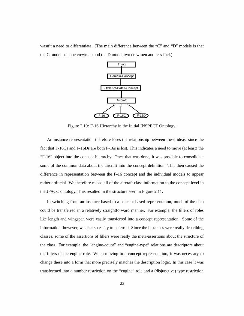
An instance representation therefore loses the relationship between these ideas, since the
fact that F-16Cs and F-16Ds are both F-16s is lost. This indicates a need to move (at least) the
“F-16” object into the concept hierarchy. Once that was done, it was possible to consolidate
some of the common data about the aircraft into the concept definition. This then caused the
difference in representation between the F-16 concept and the individual models to appear
rather artificial. We therefore raised all of the aircraft class information to the concept level in
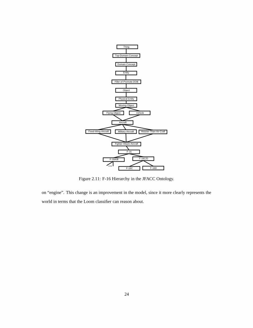
the JFACC ontology. This resulted in the structure seen in Figure 2.11.
In switching from an instance-based to a concept-based representation, much of the data
could be transferred in a relatively straightforward manner. For example, the fillers of roles
like length and wingspan were easily transferred into a concept representation. Some of the
information, however, was not so easily transferred. Since the instances were really describing
classes, some of the assertions of fillers were really the meta-assertions about the structure of
the class. For example, the “engine-count” and “engine-type” relations are descriptors about
the fillers of the engine role. When moving to a concept representation, it was necessary to
change these into a form that more precisely matches the description logic. In this case it was
transformed into a number restriction on the “engine” role and a (disjunctive) type restriction
23
Entity
Filler-of-Promote-DOB
Object
Moving-Object
Aircraft
Fixed-Wing-Aircraft Military-Aircraft
Fighter-Attack-Aircraft
F-16
Heavier-Than-Air-Craft
F-16DF-16C
F-16A/B F-16C/D
Flying-Object Vehicle
Thing
Top-Domain-Concept
Domain-Concept
Physical Entity
Figure 2.11: F-16 Hierarchy in the JFACC Ontology.
on “engine”. This change is an improvement in the model, since it more clearly represents the
world in terms that the Loom classifier can reason about.
24
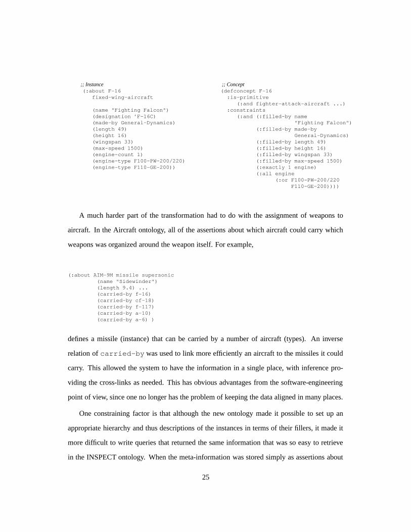
;; Instance(:about F-16
fixed-wing-aircraft
(name "Fighting Falcon")(designation ’F-16C)(made-by General-Dynamics)(length 49)(height 16)(wingspan 33)(max-speed 1500)(engine-count 1)(engine-type F100-PW-200/220)(engine-type F110-GE-200))
;; Concept(defconcept F-16:is-primitive
(:and fighter-attack-aircraft ...):constraints
(:and (:filled-by name"Fighting Falcon")
(:filled-by made-byGeneral-Dynamics)
(:filled-by length 49)(:filled-by height 16)(:filled-by wingspan 33)(:filled-by max-speed 1500)(:exactly 1 engine)(:all engine
(:or F100-PW-200/220F110-GE-200))))
A much harder part of the transformation had to do with the assignment of weapons to
aircraft. In the Aircraft ontology, all of the assertions about which aircraft could carry which
weapons was organized around the weapon itself. For example,
(:about AIM-9M missile supersonic(name "Sidewinder")(length 9.4) ...(carried-by f-16)(carried-by cf-18)(carried-by f-117)(carried-by a-10)(carried-by a-6) )
defines a missile (instance) that can be carried by a number of aircraft (types). An inverse
relation of carried-by was used to link more efficiently an aircraft to the missiles it could
carry. This allowed the system to have the information in a single place, with inference pro-
viding the cross-links as needed. This has obvious advantages from the software-engineering
point of view, since one no longer has the problem of keeping the data aligned in many places.
One constraining factor is that although the new ontology made it possible to set up an
appropriate hierarchy and thus descriptions of the instances in terms of their fillers, it made it
more difficult to write queries that returned the same information that was so easy to retrieve
in the INSPECT ontology. When the meta-information was stored simply as assertions about
25
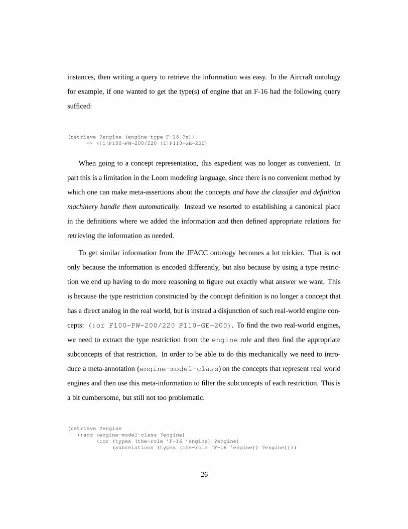
instances, then writing a query to retrieve the information was easy. In the Aircraft ontology
for example, if one wanted to get the type(s) of engine that an F-16 had the following query
sufficed:
(retrieve ?engine (engine-type F-16 ?x))=> (|i|F100-PW-200/220 |i|F110-GE-200)
When going to a concept representation, this expedient was no longer as convenient. In
part this is a limitation in the Loom modeling language, since there is no convenient method by
which one can make meta-assertions about the concepts and have the classifier and definition
machinery handle them automatically. Instead we resorted to establishing a canonical place
in the definitions where we added the information and then defined appropriate relations for
retrieving the information as needed.
To get similar information from the JFACC ontology becomes a lot trickier. That is not
only because the information is encoded differently, but also because by using a type restric-
tion we end up having to do more reasoning to figure out exactly what answer we want. This
is because the type restriction constructed by the concept definition is no longer a concept that
has a direct analog in the real world, but is instead a disjunction of such real-world engine con-
cepts: (:or F100-PW-200/220 F110-GE-200). To find the two real-world engines,
we need to extract the type restriction from the engine role and then find the appropriate
subconcepts of that restriction. In order to be able to do this mechanically we need to intro-
duce a meta-annotation (engine-model-class) on the concepts that represent real world
engines and then use this meta-information to filter the subconcepts of each restriction. This is
a bit cumbersome, but still not too problematic.
(retrieve ?engine(:and (engine-model-class ?engine)
(:or (types (the-role ’F-16 ’engine) ?engine)(subrelations (types (the-role ’F-16 ’engine)) ?engine))))
26
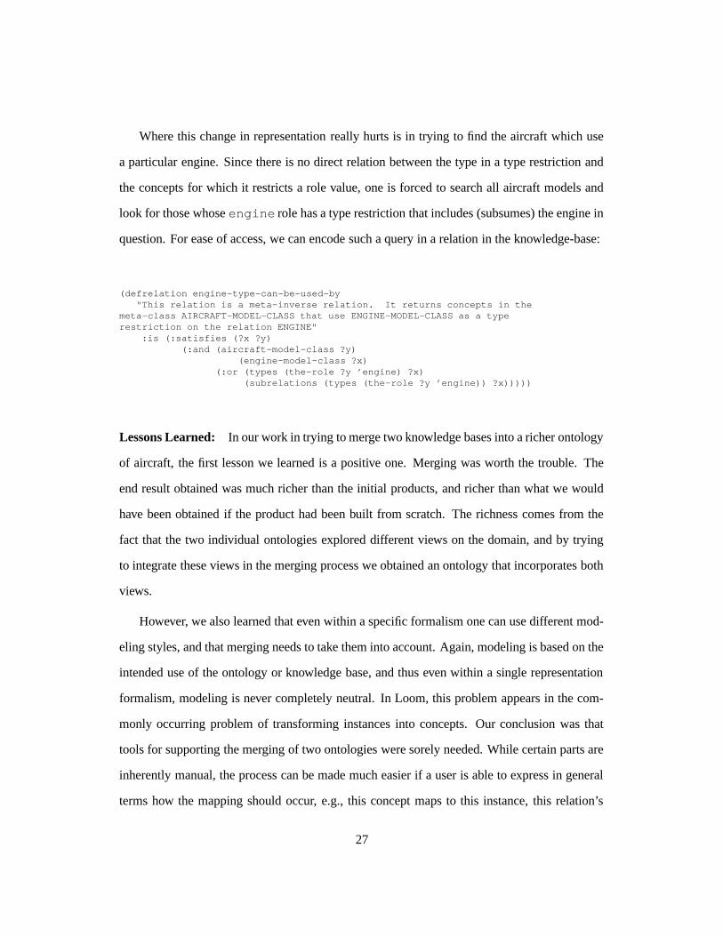
Where this change in representation really hurts is in trying to find the aircraft which use
a particular engine. Since there is no direct relation between the type in a type restriction and
the concepts for which it restricts a role value, one is forced to search all aircraft models and
look for those whose engine role has a type restriction that includes (subsumes) the engine in
question. For ease of access, we can encode such a query in a relation in the knowledge-base:
(defrelation engine-type-can-be-used-by"This relation is a meta-inverse relation. It returns concepts in the
meta-class AIRCRAFT-MODEL-CLASS that use ENGINE-MODEL-CLASS as a typerestriction on the relation ENGINE"
:is (:satisfies (?x ?y)(:and (aircraft-model-class ?y)
(engine-model-class ?x)(:or (types (the-role ?y ’engine) ?x)
(subrelations (types (the-role ?y ’engine)) ?x)))))
Lessons Learned: In our work in trying to merge two knowledge bases into a richer ontology
of aircraft, the first lesson we learned is a positive one. Merging was worth the trouble. The
end result obtained was much richer than the initial products, and richer than what we would
have been obtained if the product had been built from scratch. The richness comes from the
fact that the two individual ontologies explored different views on the domain, and by trying
to integrate these views in the merging process we obtained an ontology that incorporates both
views.
However, we also learned that even within a specific formalism one can use different mod-
eling styles, and that merging needs to take them into account. Again, modeling is based on the
intended use of the ontology or knowledge base, and thus even within a single representation
formalism, modeling is never completely neutral. In Loom, this problem appears in the com-
monly occurring problem of transforming instances into concepts. Our conclusion was that
tools for supporting the merging of two ontologies were sorely needed. While certain parts are
inherently manual, the process can be made much easier if a user is able to express in general
terms how the mapping should occur, e.g., this concept maps to this instance, this relation’s
27
filler are mapped into that relation’s restrictions, etc. This calls for a tool that incorporates a
language to talk about ontologies, their relations and relations among their components. Map-
pings should be described declaratively in this (meta-)language. To this end, concept represen-
tations like the one used in Loom can be less convenient because they are more general, but
harder to manipulate. It is important to find a graphical representation for this (meta-)language,
that can be used in constructing tools that are visually rich and easy to use. To date, a few tools
supporting the process of ontology merging are available [14, 3, 12], however, the problem is
far from being solved and more research is needed to better support ontology merging efforts
in the future.
2.4 Organization of the JFACC Ontology
In constructing the JFACC ontology, an important issue was how to organize the ontology so as
to make its maintenance easier and its construction more rational. Following almost standard
guidelines found in the literature (e.g., the micro-theories of [9]), we decided to modularize the
ontology. In our experience, modularization is a pretty natural process: even before deciding
explicitly to use modularization, we already separated different sections of the ontology into
several files that reflected the different parts of the domain: plans, aircraft, etc. However, what
is lacking in this sort of “weak” modularization is the notion of dependencies between these
sub-ontologies. That is, even though a given file encapsulates most of the knowledge about a
domain element (say, aircraft), it is not clear which other definitions (say, of physical objects)
are necessary to be able to use the knowledge in that file.
As a second step, we used Loom contexts to obtain modularization. A Loom context con-
tains a symbol table that maps a collection of names (logical constants) onto corresponding
associated logical entities (relations and individuals). Each context inherits zero or more other
contexts; if a context C2 inherits a context C1 than all names and entities belonging to C1 also
belong to (are visible to) C2. Unlike, e.g., Common Lisp packages, inheritance is transitive—if
28
context C3 inherits C2, than C3 also inherits C1. Figure 2.12 shows the inheritance lattice for
the JFACC ontology. Each node in the inheritance hierarchy is considered to define its own
(sub)ontology, so ontologies are mapped one-to-one onto contexts. In the remainder of this
section, we will use the terms context and ontology as if they were synonymous.
In some modeling situations, given a context C4, one would like the ability to reference
names defined in a context C5 that is not inherited by C4. For example, the aircraft con-
text contains many references to objects in the weapons context (and vice-versa), but neither
context should logically contain the other. Loom provides a prefixing mechanism similar to
Common Lisp prefixing of symbols that enables such cross referral; however, we find that ex-
tensive use of context prefixes is undesirable (i.e., we much prefer using unqualified names).
To “solve” the problem of implementing cross-references between the aircraft, weapons, and
fuel contexts, we found it necessary to construct an artificial context (the entities context) to
hold general versions of concepts visible to each of these other contexts. For example, the
general concept aircraft is defined in the entities context so that it can be used by the
weapons and fuel contexts (e.g. as one of the types of targets against which a weapon is meant
to be used), but the definitions for types of aircraft (fighter-aircraft, F-16) are in the
aircraft ontology.
Some newer KR systems, (e.g., PowerLoom and Ontolingua) support both an includes
relation between contexts (similar to Loom context inheritance) and a (non-transitive) uses
relation (similar to the :uses option for Common Lisp packages). We would not have found it
necessary to define the entities context if Loom offered support for both kinds of inter-context
relations.
Occasionally, we as modelers would find it convenient to specialize or shadow a concept
defined in an inherited context, thereby allowing us to define a local version of the concept
having the same name as the inherited concept. For example, we might like to define a “skele-
tal” version of airplane in entities and a more detailed version (one having more slots) in
29
the aircraft context. While, Loom does not support shadowing or same-name concept special-
ization, and few KR systems do, we feel that having this capability would be a plus.
2.4.1 The structure of the JFACC ontology
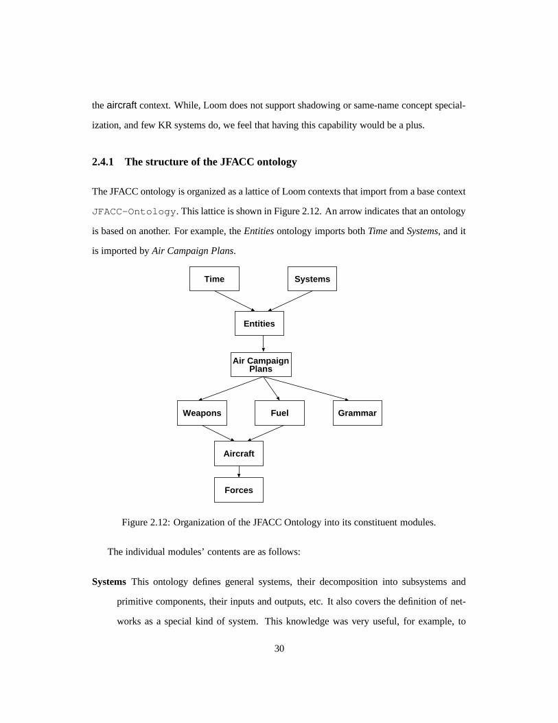
The JFACC ontology is organized as a lattice of Loom contexts that import from a base context
JFACC-Ontology. This lattice is shown in Figure 2.12. An arrow indicates that an ontology
is based on another. For example, the Entities ontology imports both Time and Systems, and it
is imported by Air Campaign Plans.
Time Systems
Entities
GrammarFuelWeapons
Aircraft
Forces
Air CampaignPlans
Figure 2.12: Organization of the JFACC Ontology into its constituent modules.
The individual modules’ contents are as follows:
Systems This ontology defines general systems, their decomposition into subsystems and
primitive components, their inputs and outputs, etc. It also covers the definition of net-
works as a special kind of system. This knowledge was very useful, for example, to
30
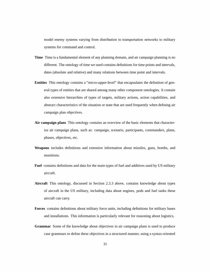
model enemy systems varying from distribution to transportation networks to military
systems for command and control.
Time Time is a fundamental element of any planning domain, and air campaign planning is no
different. The ontology of time we used contains definitions for time points and intervals,
dates (absolute and relative) and many relations between time point and intervals.
Entities This ontology contains a “micro-upper-level” that encapsulates the definition of gen-
eral types of entities that are shared among many other component ontologies. It contain
also extensive hierarchies of types of targets, military actions, action capabilities, and
abstract characteristics of the situation or state that are used frequently when defining air
campaign plan objectives.
Air campaign plans This ontology contains an overview of the basic elements that character-
ize air campaign plans, such as: campaign, scenario, participants, commanders, plans,
phases, objectives, etc.
Weapons includes definitions and extensive information about missiles, guns, bombs, and
munitions.
Fuel contains definitions and data for the main types of fuel and additives used by US military
aircraft.
Aircraft This ontology, discussed in Section 2.3.3 above, contains knowledge about types
of aircraft in the US military, including data about engines, pods and fuel tanks these
aircraft can carry.
Forces contains definitions about military force units, including definitions for military bases
and installations. This information is particularly relevant for reasoning about logistics.
Grammar Some of the knowledge about objectives in air campaign plans is used to produce
case grammars to define these objectives in a structured manner, using a syntax-oriented
31
editor. This ontology contains the concepts and relations necessary to map the repre-
sentation of objectives in the air campaign plans ontology (see above) into the grammar
representation. This is explained in detail in sectionSection 2.5, below.
Lessons learned: Structuring the JFACC ontology was not only a useful but a necessary task.
It is almost impossible to manage the contents of an ontology with more than a few hundred
entities without some kind of discipline. Creating the organization was not easy, however, and
we made several attempts to come up with the current structure. The main lesson learned in
structuring and organizing the JFACC ontology is that quite a bit of flexibility is needed from
a context mechanism — more than is available in most existing KR systems. We intend to
experiment in using an upper ontology (such as Sensus [16]) to see what benefits it can bring
in terms of modularization and organization.
2.5 Using the JFACC ontology
The JFACC Ontology was designed to be used by a wide range of applications. Currently,
we implemented its use by three applications: INSPECT, the Mastermind Objectives Editor,
and the Strategy Development Assistant (see Section 2.2 and Chapter 3 for details about these
applications). As Figure 2.13 shows, these applications use the JFACC Ontology in different
ways. The knowledge bases of INSPECT and SDA include the JFACC ontology (or a number
of its modules) and add on top of this whatever additional knowledge they need to perform
their specific tasks. However, the use of the ontology by the Mastermind Editor is far from
trivial. Below, we describe in some detail how the knowledge used by the Mastermind Editor
(represented as a grammar) is extracted from the JFACC Ontology, and how we needed to
augment the ontology to cope with two problems: the structural mismatch between the way the
knowledge was formulated in the original ontology and the target representation (a grammar),
32
and the lack of certain kinds of application-specific information in the ontology that required
the layering of the JFACC ontology to allow for several different views on the same knowledge.
Mastermind Plan Editor
INSPECT
import extract
JFACC ONTOLOGY
SDA
import
Air Campaign ObjectivesKnowledge
Mastermind-specificknowledge overlay
Mastermind Objectives Grammar
Figure 2.13: Using the JFACC Ontology in three applications: INSPECT, SDA, and the Mas-termind Plan Editor. Both INSPECT and SDA use the ontology by importing it. The Master-mind Editor uses the knowledge in a more complicated fashion. It uses an overlay to overcomeproblems of structural mismatch between the common ontology and the grammar Mastermindneeds.
The Mastermind Objectives Editor and its Adaptive Form (see Section 2.2 for details) uses
much of the same knowledge stored in the JFACC Ontology and also used by INSPECT and
SDA. The grammar that serves as input to the Adaptive Form contains information about, for
example, which verbs can be used and what objects can be used with these verbs, the structure
and contents of area, time and resource constraints, etc. Initially, both the ontology and the
grammar were generated by hand, and all the usual problems started to happen: it was very
hard to keep consistent, knowledge had to be entered twice, etc. Therefore, one of our goals
was to develop an automatic translator that used one central source (the ontology) and produced
the grammar from it.
We found two main types of problems building this translator. First, the form in which
33
this knowledge is expressed in the grammar is rather different than in the ontology. What
is expressed in Loom as concepts, relations and instances is represented in the Mastermind
grammars as BNF rules — there is a structural mismatch.4 There is no simple correspon-
dence between elements in the ontology and elements in the grammar, and thus it is necessary
to implement a non-trivial mapping between the two knowledge forms. Second, part of the
knowledge needed by the grammar (e.g., how certain slots are ordered when mapped to ele-
ments in a BNF formula) was not present in the ontology. Conversely, not all of the knowledge
had a corresponding grammar form, and should be ignored in the translation. This additional
grammar-related knowledge is not an inherent part of the domain, but only guidance about
how to use the knowledge. Consequently, we tried to separate it from the “core’ ontology by
creating an overlay that uses annotations to the ontology elements to add this information for
the translation process.
Figure 2.14 illustrates the structural mismatch problem between the concept acp-objective
and the BNF rule that results from the mapping/translation process. As we can see, there are
several types of mismatch. Some of the types of mismatch relate to the way a specific slot is
mapped, others to the way the non-terminal representing that slot in the grammar is going to
be produced in the mapping process.
� Some elements of the Loom ontology have no direct mapping into the Mastermind gram-
mar. For example, the slot objective-issued-by has no correspondence in the
grammar. This occurs because not all knowledge which is relevant for the ontology is
relevant for the grammar.
� The way the mapping is done may depend on the specific slot. Some slots, like objective-
verb, are not mapped directly into the expansion of the non-terminal objective, but their
mapping is delayed to take into account dependencies between its fillers and the fillers
4Indeed, one can see this difference as a consequence of the two distinct views underlying the representationsin Loom and in BNF.
34
(defconcept acp-objective:is-primitive time-range-bound-concept:roles((objective-statement :type String)(objective-issued-by :type commander)(objective-supports:type acp-objective)
(objective-verb :type verb)(objective-role :type entity)(objective-measures-of-merit:type measure-of-merit)
(objective-area-restriction:type area :max 1)
(objective-time-restriction:type time-restriction :max 1)
(objective-resource-specification:type force-package)))
(defrelation DOB-role:is-primitive objective-role)
(defconcept Deploy-forces-template:roles ((DOB-role :facets
((order-info 1)))):is (:and acp-objective
(:filled-by objective-verbDeploy)
(:exactly 1 objective-role)(:the DOB-role forces)))
objective "Objective":’attrit’ redObject |’damage’ redObject |’deceive’ redObject |’deny’ redAction ’to’ redObject |’deploy’ forces | ...
..........
redObject "Red Object":objectTerminals ofRedOwner;
redOwner "Red Owner" :redSpecial | redCountryTerminals;
forces "Forces":forceType forceNumber;
..........
areaRestriction "Where":areaModifier area;
areaModifier "areaModifier":’over’ | ’in’ | ’at’;
area "Area" :country | geographicRegion |conflictSide;
Figure 2.14: How the knowledge about the use of the verb “deploy” is expressed in the JFACCOntology (Loom, left) and the Mastermind grammar (BNF, right). The concept Deploy-template expresses how the verb deploy is used — that is, which kinds of the roles it canaccept (specifically, the direct object, symbolized here by DOB-role), and which kinds ofobjects can fill these roles (specifically, subtypes of the type forces).
of other slots — specifically, objective-role in its subtypes, such as DOB-role.
Other slots, like objectivearea-restriction, are mapped directly into the ex-
pansion of the non-terminal objective. The basic question is whether or not any
subtypes of the concept acp-objective may introduce a relationship between the
fillers of two roles of the parent concept. If there is no such relationship, we mapped
the slots into non-terminal in the grammar rule for objective. Otherwise, we leave the
mapping of the slots to be done at a subsequent rule or expansion.
� The way a mapping is constructed to build the grammar rule for a specific non-terminal
is also dependent on how the knowledge about this non-terminal was structured in Loom.
35
For example, given a specific non-terminal expressed in the Loom ontology as a concept,
the right hand side of the rule corresponding to that concept may be constructed by listing
instances of the concept, by listing subconcepts of that concept, or by mapping separately
each of the slots (relations) associated with that concept. The same occurs for mapping
non-terminals which correspond to relations in Loom.
The basic strategy we adopted to cope with these two problems is to introduce annotations
in the basic ontology that determine how specific concepts or slots are mapped into BNF rules
or elements of these rules. Figure 2.15 illustrates how these annotations are introduced. It
shows an expanded definition of the concept deploy-template, as well as some additional
elements of the Loom ontology and some other grammar rules that result from their translation.
As we can see in the figure, the annotations are introduced in two places. First, we introduce
annotations on the slots of specific concept by adding facets to it. We introduced two facets:
order-info and fill-by:
� The order-info facet is used to overcome one of the incompleteness problems. It
adds the information about the order of the slots when they are mapped into elements
of the right side of a BNF rule. For example, the order-info annotations in slots of
the concept Deploy-object-template express the additional information that the
contents corresponding to the slots objective-verb are to appear first (i.e., leftmost)
into the grammar rule, the contents corresponding to DOB-role are to appear second,
etc. This annotation is also used to exclude the use of certain slots, that is, every slot or
relation over the concept deploy-object-template that has no specific order-
info information is not mapped into an element of the grammar rule.
� The fill-by facet is used to solve the structural mismatch problems for slots. It indi-
cates how a specific slot is supposed to be mapped into an element of a grammar rule.
There are three possible fillers for the filled-by facet:
36
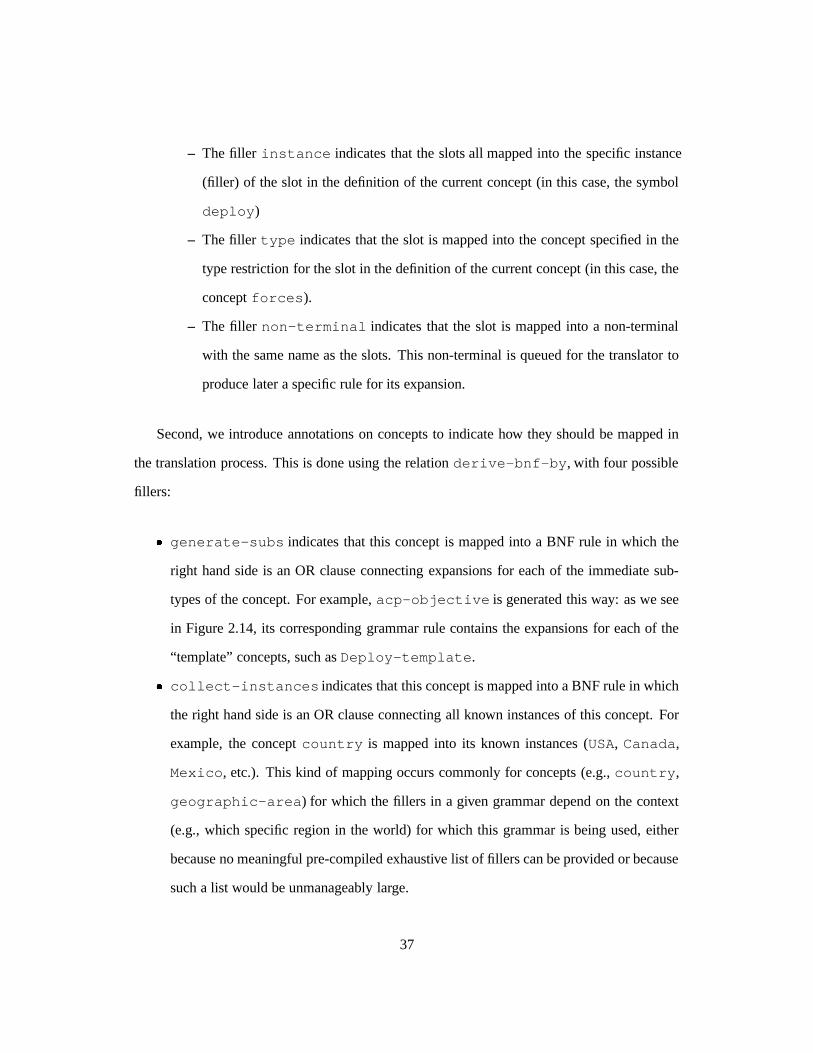
– The filler instance indicates that the slots all mapped into the specific instance
(filler) of the slot in the definition of the current concept (in this case, the symbol
deploy)
– The filler type indicates that the slot is mapped into the concept specified in the
type restriction for the slot in the definition of the current concept (in this case, the
concept forces).
– The filler non-terminal indicates that the slot is mapped into a non-terminal
with the same name as the slots. This non-terminal is queued for the translator to
produce later a specific rule for its expansion.
Second, we introduce annotations on concepts to indicate how they should be mapped in
the translation process. This is done using the relation derive-bnf-by, with four possible
fillers:
� generate-subs indicates that this concept is mapped into a BNF rule in which the
right hand side is an OR clause connecting expansions for each of the immediate sub-
types of the concept. For example, acp-objective is generated this way: as we see
in Figure 2.14, its corresponding grammar rule contains the expansions for each of the
“template” concepts, such as Deploy-template.
� collect-instances indicates that this concept is mapped into a BNF rule in which
the right hand side is an OR clause connecting all known instances of this concept. For
example, the concept country is mapped into its known instances (USA, Canada,
Mexico, etc.). This kind of mapping occurs commonly for concepts (e.g., country,
geographic-area) for which the fillers in a given grammar depend on the context
(e.g., which specific region in the world) for which this grammar is being used, either
because no meaningful pre-compiled exhaustive list of fillers can be provided or because
such a list would be unmanageably large.
37
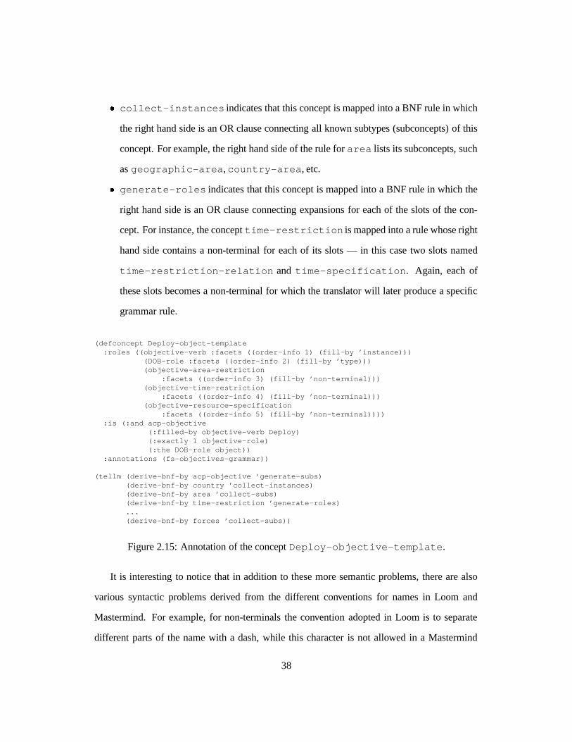
� collect-instances indicates that this concept is mapped into a BNF rule in which
the right hand side is an OR clause connecting all known subtypes (subconcepts) of this
concept. For example, the right hand side of the rule for area lists its subconcepts, such
as geographic-area,country-area, etc.
� generate-roles indicates that this concept is mapped into a BNF rule in which the
right hand side is an OR clause connecting expansions for each of the slots of the con-
cept. For instance, the concept time-restriction is mapped into a rule whose right
hand side contains a non-terminal for each of its slots — in this case two slots named
time-restriction-relation and time-specification. Again, each of
these slots becomes a non-terminal for which the translator will later produce a specific
grammar rule.
(defconcept Deploy-object-template:roles ((objective-verb :facets ((order-info 1) (fill-by ’instance)))
(DOB-role :facets ((order-info 2) (fill-by ’type)))(objective-area-restriction
:facets ((order-info 3) (fill-by ’non-terminal)))(objective-time-restriction
:facets ((order-info 4) (fill-by ’non-terminal)))(objective-resource-specification
:facets ((order-info 5) (fill-by ’non-terminal)))):is (:and acp-objective
(:filled-by objective-verb Deploy)(:exactly 1 objective-role)(:the DOB-role object))
:annotations (fs-objectives-grammar))
(tellm (derive-bnf-by acp-objective ’generate-subs)(derive-bnf-by country ’collect-instances)(derive-bnf-by area ’collect-subs)(derive-bnf-by time-restriction ’generate-roles)...(derive-bnf-by forces ’collect-subs))
Figure 2.15: Annotation of the concept Deploy-objective-template.
It is interesting to notice that in addition to these more semantic problems, there are also
various syntactic problems derived from the different conventions for names in Loom and
Mastermind. For example, for non-terminals the convention adopted in Loom is to separate
different parts of the name with a dash, while this character is not allowed in a Mastermind
38
grammar. Therefore, all dash characters in the names of non-terminals must be eliminated
in the translation process (e.g., time-restriction is transformed into timerestric-
tion). For terminals, the treatment of these characters is different. Because we want to obtain
human-readable names, the dashes are transformed into spaces. In addition, the names are
surrounded by single quotes (’) — e.g., military-communications is transformed into
’military communications’. For the cases in which a translation using these simple
rules of thumb is not adequate, we introduced another type of annotation using the relation
human-name, in which an arbitrary human name (string) may be specified as a mapping for
a given Loom name. This is useful for translations in which case is important (for example
southern-california into ’Southern California’) as well as more exceptional
cases such as the relation DOB-role, which must be translated into the empty string.
Lessons learned: The problems we found in trying to use the JFACC ontology in several
applications are to some extent similar to those we found in importing an external ontology.
This occurs in part because we also had to translate the ontology to a different formalism, and
thus found the same mismatch and use bias problems we discussed in section Section 2.3.2.
The gist of the solution we found for this problem (annotating the original ontology constructs
to indicate their mapping into the Mastermind grammar) can thus be seen as a possible mech-
anism to be used in ontology translations. What the annotations allow is for a use to “drive”
or “customize” to some extent the translation process to allow for a more precise mapping
between source and target ontologies. However, we had an additional problem, which is that
the knowledge in the original ontology was incomplete. The solution to this problem was to
structure the knowledge in layers, so that the use-specific knowledge is separated as much
as possible from the core (and more reusable) knowledge. While we did not intend this to
be a general solution to usability problems, we believe these mechanisms can be used more
generally to solve similar problems in other ontologies, provided the formalism used in those
ontologies allows for layering and the use of annotations as we did here.
39
2.6 Conclusions
Building the JFACC Ontology was an extremely interesting and useful enterprise. We ob-
tained all the benefits we envisioned in the beginning of the process — namely, to facilitate
inter-operation and communication between systems to promote sharing of knowledge be-
tween systems, to integrate our knowledge acquisition, and to offer a repository for general
knowledge about air campaign planning that could be used in several applications. We also
used the ontolgoy to bridge the gap between knowledge-based and “traditional” systems, sub-
stituting or superceding the usual database or object-oriented schema with an ontology, which
offers a semantically richer model of the domain.
Our experience has shown that reusability is both desirable and possible. Having a well-
structured ontology of a domain provides a basis on which to build, and thus helps enormously
to develop new systems on that domain. For example, the SDA was created after the JFACC
Ontology was already in place, and its construction demanded much less knowledge acqui-
sition and modeling than previous applications did. In fact, not having to worry about the
basic modeling problems enabled us in the development of the SDA to spend more time in the
representation issues related to SDA’s problem solving methods, saving considerable time and
allowing us to produce a better system.
However, we found that actually building, using and reusing ontologies requires a lot of
manual work and a lot of difficult modeling decisions, even when using some of the best and
most mature knowledge representation formalisms currently available. Above we described
some important, general problems, and how we solved them in the JFACC ontology. First, dif-
ferences in modeling styles and underlying views or upper models in different formalisms can
cause problems in translating and merging. The intended use of ontologies (expressed in the
inferencing bias) must be considered in the translation process to make the translation products
more useful. Second, these problems appear even when merging several ontologies originally
constructed in the same formalism. A specific formalism restricts some modeling choices, but
40

there are still a lot of options available for the ontological engineer in how to use the constructs
available. As a consequence, different people can construct quite different representations of
the same knowledge. What we want to do is to be able to distinguish what is behind these
choices, and what consequences they entail, so that the merging can result in a richer ontology
that combines the best of both initial ontologies. Third, weaknesses in the context mechanisms
currently available can cause problems in trying to organize and modularize large ontologies.
Fourth, trying to use an ontology in several applications can be very nontrivial, and can also
require a translation process similar and equally difficult to the one used in importing an ontol-
ogy. We found it is difficult to structure an ontology to be used in different applications, and
an interesting solution is to maintain a core representation and layer additional information
necessary to make specific uses of the knowledge in this core.
Finally, while we were able to find adequate solutions for all the technical problems we
found in developing the JFACC ontology, general solutions to these problems are difficult
to come by. We believe, however, that practical experiences in building, using, and reusing
ontologies are extremely important in directing research in ontological engineering.
41
Chapter 3
The Strategy Development Assistant
(SDA)
3.1 Overview
In this chapter we describe a knowledge-based system for aiding Air Campaign Planning. An
early part of this process involves the decomposition of high level objectives into more specific
sub-objectives. We developed a program called Strategy Development Assistant (SDA) that
assists the user in this decomposition process. The SDA is a knowledge-based system, whose
knowledge base was initially based on a theory of air warfare. The SDA provides suggested
decompositions based on the current situation and high-level goals.
The SDA is used to support military planners in an early phase of air campaign planning.
The choice of decompositions is template-driven, based on a set of underlying assumptions.
The SDA’s graphical user interface details the assumptions, allows the user to modify the values
of the assumptions and, thus, captures the assumptions underlying the plan. The SDA is a truly
mixed-initiative planning system. All elements of the interface design are geared towards
giving the user total control of the decisions taken in the decomposition process.
42
Air Campaign Plans are plans prepared by the US Military that describe the conduct of
an air campaign: what objectives are going to be achieved, when, and how. These plans are
represented as a hierarchy of objectives. Top-level strategic objectives are recursively decom-
posed into several layers of lower-level objectives, until each objective is associated with a
specific aircraft flying one mission. Developing an air campaign plan is a complex task, in
which several factors have to be weighed and many decisions have to be made. However, users
are wary of automating the whole process, for example, by using a generative planner such as
SIPE [13]. This is, since military planners feel they need to have control over each element
of the plan and the planning process, and need to understand in detail the rationale for each
objective decomposition. For this reason, mixed-initiative systems that keep the human “in the
loop” seem to be the best option to provide computerized support to the planning process.
As part of our work for the JFACC program, we implemented a knowledge-based system
for aiding in the decomposition of planning objectives. Our Strategy Development Assistant
proposes one or more decompositions for a user-selected objective. The SDA uses a library of
decomposition templates derived from a theory of air campaign planning provided by an expert
in the field. SDA aids users in making the necessary decisions in customizing these decompo-
sitions by examining situation information from available databases (see Figure3.1). The SDA
is implemented using Loom, a knowledge representation and reasoning system developed at
ISI [10]. It works as an assistant that is invoked from a Java-based Air Campaign Plan Editor.
The idea is that users should be free to plan with or without the SDA, as they prefer. This
architecture also highlights the role of the SDA as an assistant, not a full planner.
The main goal of the SDA was to accelerate the pace of planning by providing sets of sug-
gested decompositions. In this way we avoid the “blank sheet of paper” syndrome by providing
guidance. The system can also speed up the planning process. For example, in emergency situ-
ations the user may prefer to provide minimal input and let the SDA decompose several levels
of objectives in the plan, making all modifications in the end. Another important benefit is
43
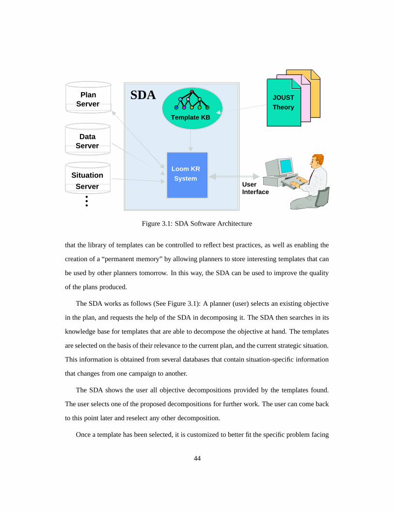
PlanServer
DataServer
JOUST
Theory
Template KB
SDA
Loom KR
SystemUserInterface...
Situation
Server
Figure 3.1: SDA Software Architecture
that the library of templates can be controlled to reflect best practices, as well as enabling the
creation of a “permanent memory” by allowing planners to store interesting templates that can
be used by other planners tomorrow. In this way, the SDA can be used to improve the quality
of the plans produced.
The SDA works as follows (See Figure 3.1): A planner (user) selects an existing objective
in the plan, and requests the help of the SDA in decomposing it. The SDA then searches in its
knowledge base for templates that are able to decompose the objective at hand. The templates
are selected on the basis of their relevance to the current plan, and the current strategic situation.
This information is obtained from several databases that contain situation-specific information
that changes from one campaign to another.
The SDA shows the user all objective decompositions provided by the templates found.
The user selects one of the proposed decompositions for further work. The user can come back
to this point later and reselect any other decomposition.
Once a template has been selected, it is customized to better fit the specific problem facing
44
the planner. In the customization process, the planner generally needs to add or remove ob-
jectives in the decomposition proposed. The key to this customization process (and the most
important aspect in the system and interface design) is the use of assumptions to explain the
rationale behind each sub-objective and help the user decide whether to keep or not keep the
sub-objective. We will provide further detail on this in the rest of the paper.
When the user is satisfied with the customized decomposition, the system adds the new
objectives to the current plan, and returns control to the plan editor. At this point, the user is
again able to modify any part of the new objectives.
One of the important features of SDA that adds intelligence to the process is how it keeps
track of the assumptions behind objectives added to the plan even after the addition has been
made. For example, if the situation changes and it seems like one of the objectives that was
omitted should now be included, the SDA can warn the user and recommend the decision be
revised. If the new situation indicates one of the current objectives doesn’t make sense any
longer, SDA can recommend its removal.
The customization provides a lot of the power of the system, but also poses a problem—
how to communicate the information to the user in a way that is clear and succinct. In the
remainder of this paper, we present our solution to this problem and describe some of the
design principles behind the SDA interface.
3.2 Principles of Design
The SDA is part of a larger mixed-initiative planner. Our design philosophy is to provide as
much information as possible in a clear, succinct manner; provide suggested alternatives for
the plan; and leave the user in ultimate control. We also wanted the interface to encourage the
use of direct interaction, since that makes it easier to operate without extensive training.
45
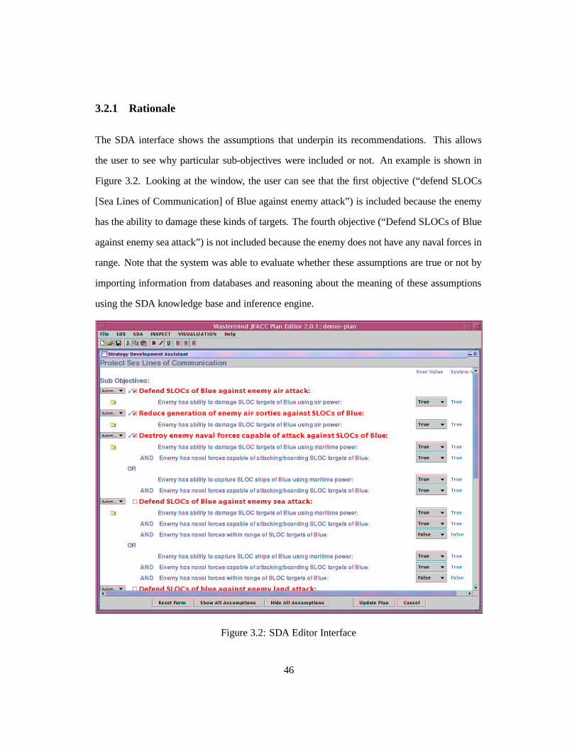
3.2.1 Rationale
The SDA interface shows the assumptions that underpin its recommendations. This allows
the user to see why particular sub-objectives were included or not. An example is shown in
Figure 3.2. Looking at the window, the user can see that the first objective (“defend SLOCs
[Sea Lines of Communication] of Blue against enemy attack”) is included because the enemy
has the ability to damage these kinds of targets. The fourth objective (“Defend SLOCs of Blue
against enemy sea attack”) is not included because the enemy does not have any naval forces in
range. Note that the system was able to evaluate whether these assumptions are true or not by
importing information from databases and reasoning about the meaning of these assumptions
using the SDA knowledge base and inference engine.
Figure 3.2: SDA Editor Interface
46
Although the SDA has access to information about the situation, we wanted the user to be
in control. Aside from the general desirability of this from a user-interaction standpoint, it was
critical for this application, since we were not so arrogant as to imagine that we would always
be able to get the right answer. There is nothing more frustrating for a user than to not be able
to fix problems in the computer’s output.
Our task was complicated because there were two levels at which we allowed user inter-
action with the interface: Users could modify the value of the assumptions underlying the
planning and have the effects propagate through to the recommendations. Users could also
directly override the recommendations. The former course of action allows the system to be
more useful as a whole, because it identifies the assumptions under which the user is changing
the system output.
The identification of these assumption changes provides a hook for other parts of the system
to monitor the resulting plan. If later information becomes available which indicates that the
assumptions the user made in adding information to the plan was wrong, the system has a
record of that dependency. The decision in question can be revisited. This ability to monitor
more of the background of the plan
3.3 Particular Challenges
In designing the interface, there were a few particular challenges that we needed to address in
order to produce a good, functional interface.
3.3.1 Displaying the Recommendation
The first task was to show the user the recommended objectives for inclusion. Because we
allow user overrides, we wanted the recommendation to be displayed as a distinct interface
element from the actual choice of whether the objective was included or not. Since inclusion
47
was a binary decision, the obvious element to use was a checkbox. We then chose to use
a similar element to indicate the recommendation, since that provides a strong visual link
between the two elements. We chose to use a check mark outside a box. This provided a visual
link between the two checks, but by not having the box around the recommendation, the active
element was differentiated from the system-controlled element.
3.3.2 Indicating Control
Since this is a mixed-initiative system, either the SDA or the user could be ultimately re-
sponsible for a particular objective being in the plan or not. We needed a way to convey the
information about “who made the decision” in an intuitive and compact way.
That is because (at different times) either the system or the user can control whether a
particular objective should be included. In automatic mode, the recommendation and the state
of the objective will always be the same, in other words the two interface elements are linked.
In manual mode, the recommendation can still change, but the actual inclusion is under the
control of the user rather than the system. In other words the recommendation indicator and
the inclusion checkbox are not linked.
Too Compact
Our first design for indicating that the recommendation and the objective inclusion box were
coupled was to use a graphic element (called a drawbridge1) that either showed a connection
or no connection. This design (see Figure 3.3) was compact and very clever, but was finally
judged to be too obscure.
48
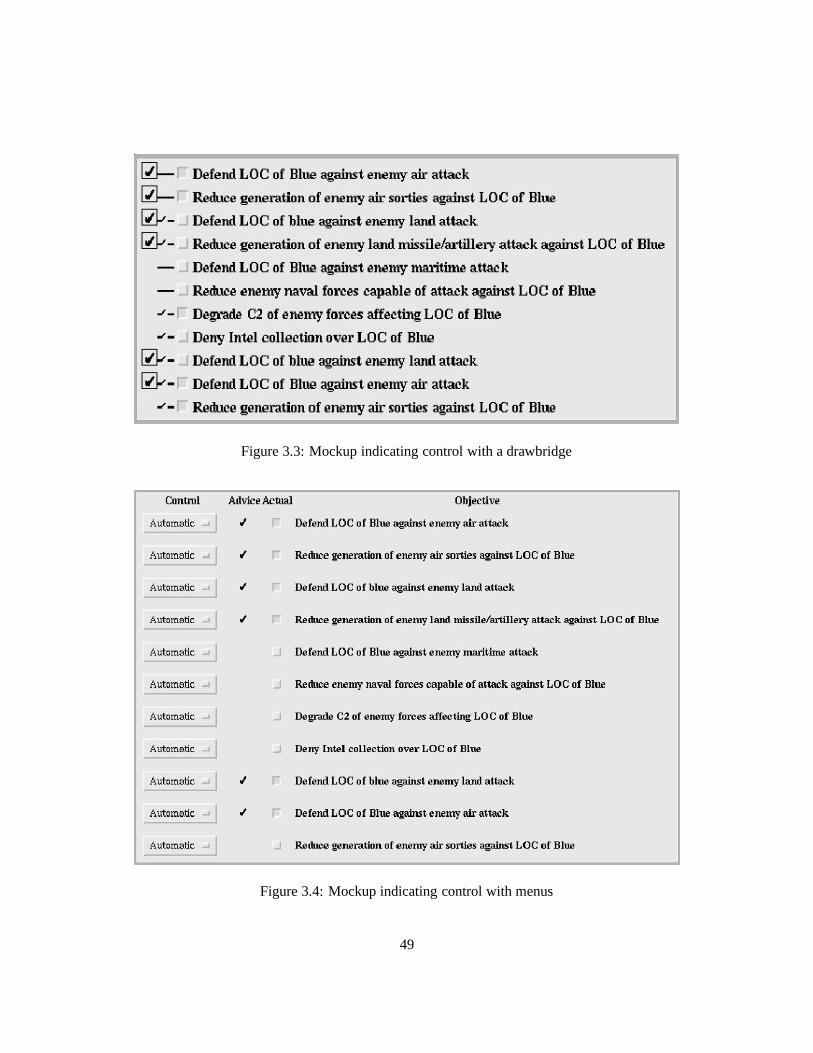
Figure 3.3: Mockup indicating control with a drawbridge
Figure 3.4: Mockup indicating control with menus
49
Clarity
We sadly had to abandon the drawbridge. We replaced it with a pop-up menu that indicates
the choice between automatic and manual control (see Figure 3.4). Although less compact, the
extra clarity was deemed worth the cost in screen real estate. With the control on “Automatic”,
the system has control of the inclusion box and can change it if the user changes the values of
the underlying assumptions.
In “Manual”, the user has full control over the inclusion box. The recommendation may
change, but the check box can only be modified by user interaction. By continuing to display
the recommendation, it is clear at a glance where the user has made a different choice than the
system would recommend.
3.3.3 Linking Controls
To make the system work reasonable well, we needed to link the controls. For example, if
the user wishes to override the system recommendation, a click in the inclusion checkbox will
change the value of the checkbox. It will also shift the control from automatic to manual.
If the user wants to return control to the system, then automatic can be selected in the pop-
up menu. The system then gains control of the inclusion checkbox and will immediately set
the inclusion value to be the same as the recommendation.
The control linkage was done in order to make direct manipulation of the interface elements
possible, and to minimize both the number of gestures demanded of the user, and to eliminate
the need to go through a more involved procedure with error feedback.
1The drawbridge happens to look exactly like the electrical circuit symbol for a switch, but we chose a differentname so as not to appear to be too nerdly.
50
3.4 Conclusions
The Strategy Development Assistant is a mixed-initiative knowledge-based planning system
for helping users develop air campaign plans. Some of the main features of the system are its
use of assumptions to keep track of the rationale behind the decisions proposed by the system
and ultimately made by the user. The interface of the SDA is able to dynamically adjust its
contents to a particular situation. This required a flexible front-end. The contents are defined
at run-time using the contents of the knowledge base as well as situation-specific information
By understanding why each element is present, the SDA can provide intelligent support to the
users’ decisions, while leaving them control over the final word over what is decided.
3.5 An Annotated Demo
Below we describe an integrated demo given at the May-98 PI meeting and shortly after in
Hurlburt, Florida. An extended version was presented at ISTI-98. The demo integrates tools
developed by three separate groups here at ISI as part of their JFACC participation: The Mas-
termind Plan Editor developed by the Mastermind group led by Pedro Szekeley, the Strategy
Development Assistant developed by our group (the Loom group), and the INSPECT plan cri-
tiquer developed by the EXPECT group led by Yolanda Gil. All three tools make extensive use
of the JFACC ontology developed by us.
Transition In: While Campaign Assessment continues to analyze the enemy forces and thus
lay the groundwork for offensive air campaign planning, other planners are working in parallel
on the immediate problems of bringing forces into the theater and preparing a defense. Master-
Mind: The Plan Editor allows users to enter objectives using grammar-based adaptive forms.
This technology provides a flexible, English-like interface, while producing objectives that are
constrained by the grammar to be understandable to the automated planning tools.
51
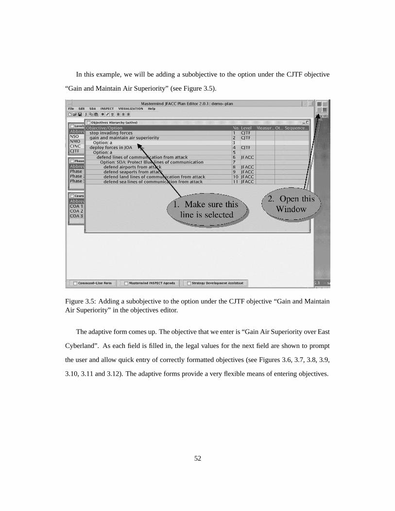
In this example, we will be adding a subobjective to the option under the CJTF objective
“Gain and Maintain Air Superiority” (see Figure 3.5).
Figure 3.5: Adding a subobjective to the option under the CJTF objective “Gain and MaintainAir Superiority” in the objectives editor.
The adaptive form comes up. The objective that we enter is “Gain Air Superiority over East
Cyberland”. As each field is filled in, the legal values for the next field are shown to prompt
the user and allow quick entry of correctly formatted objectives (see Figures 3.6, 3.7, 3.8, 3.9,
3.10, 3.11 and 3.12). The adaptive forms provide a very flexible means of entering objectives.
52
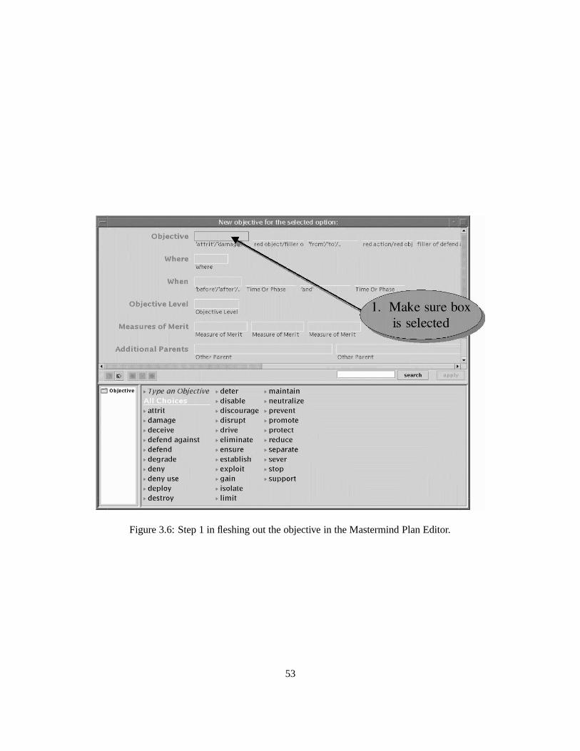
Figure 3.6: Step 1 in fleshing out the objective in the Mastermind Plan Editor.
53
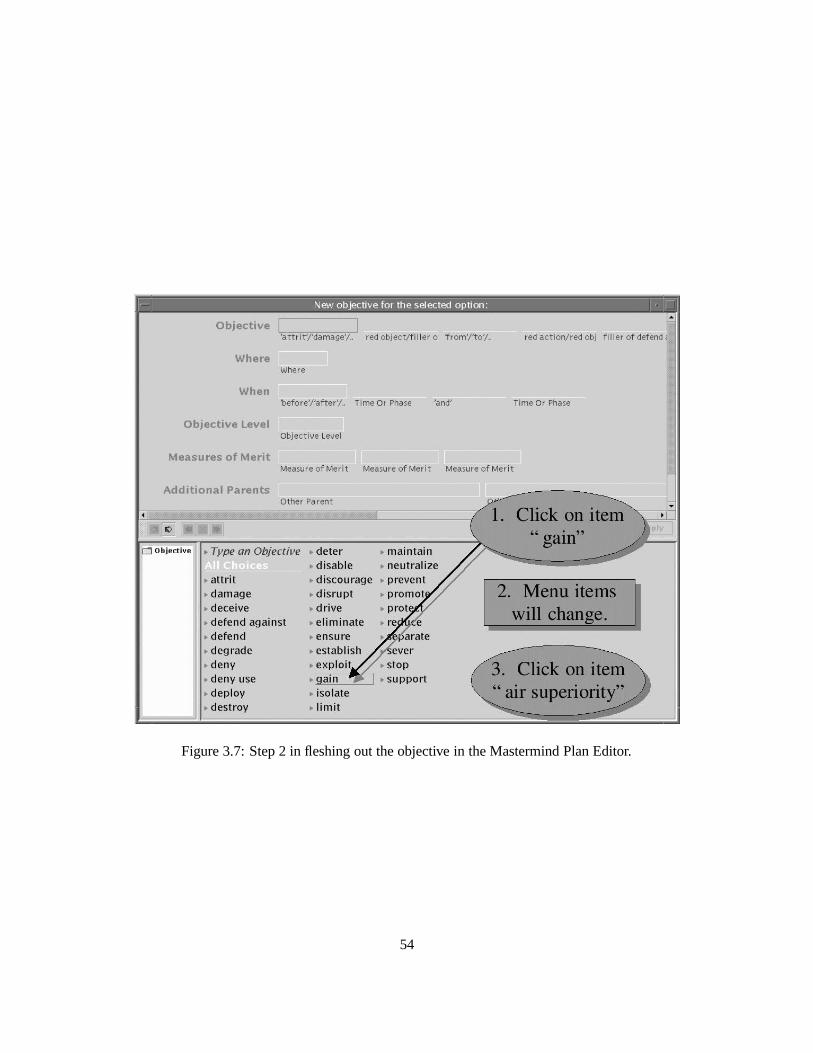
Figure 3.7: Step 2 in fleshing out the objective in the Mastermind Plan Editor.
54
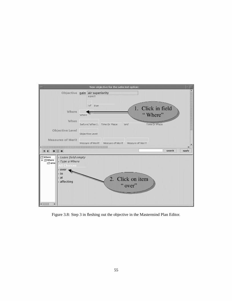
Figure 3.8: Step 3 in fleshing out the objective in the Mastermind Plan Editor.
55
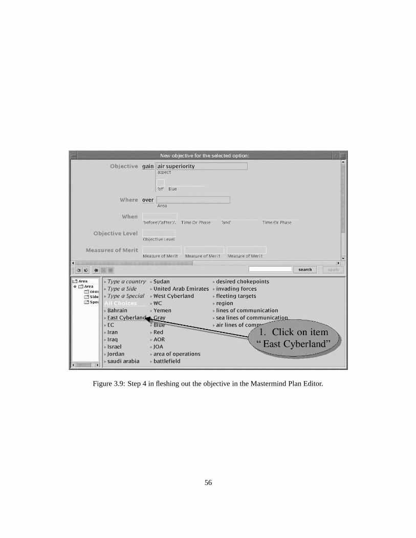
Figure 3.9: Step 4 in fleshing out the objective in the Mastermind Plan Editor.
56
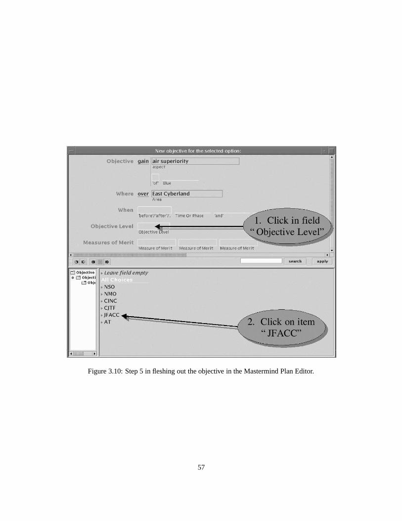
Figure 3.10: Step 5 in fleshing out the objective in the Mastermind Plan Editor.
57
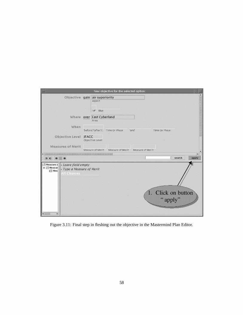
Figure 3.11: Final step in fleshing out the objective in the Mastermind Plan Editor.
58
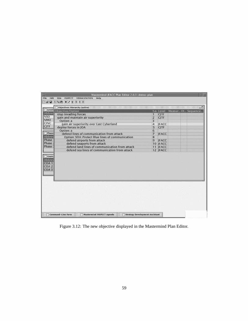
Figure 3.12: The new objective displayed in the Mastermind Plan Editor.
59
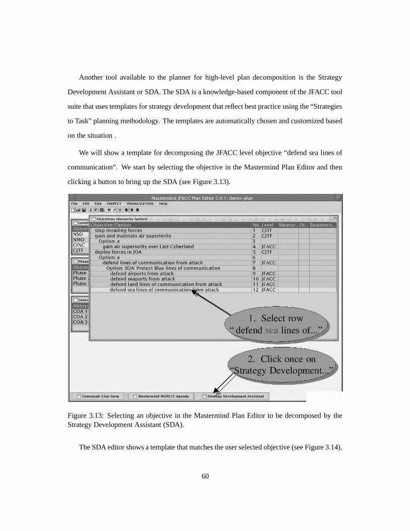
Another tool available to the planner for high-level plan decomposition is the Strategy
Development Assistant or SDA. The SDA is a knowledge-based component of the JFACC tool
suite that uses templates for strategy development that reflect best practice using the “Strategies
to Task” planning methodology. The templates are automatically chosen and customized based
on the situation .
We will show a template for decomposing the JFACC level objective “defend sea lines of
communication”. We start by selecting the objective in the Mastermind Plan Editor and then
clicking a button to bring up the SDA (see Figure 3.13).
Figure 3.13: Selecting an objective in the Mastermind Plan Editor to be decomposed by theStrategy Development Assistant (SDA).
The SDA editor shows a template that matches the user selected objective (see Figure 3.14).
60
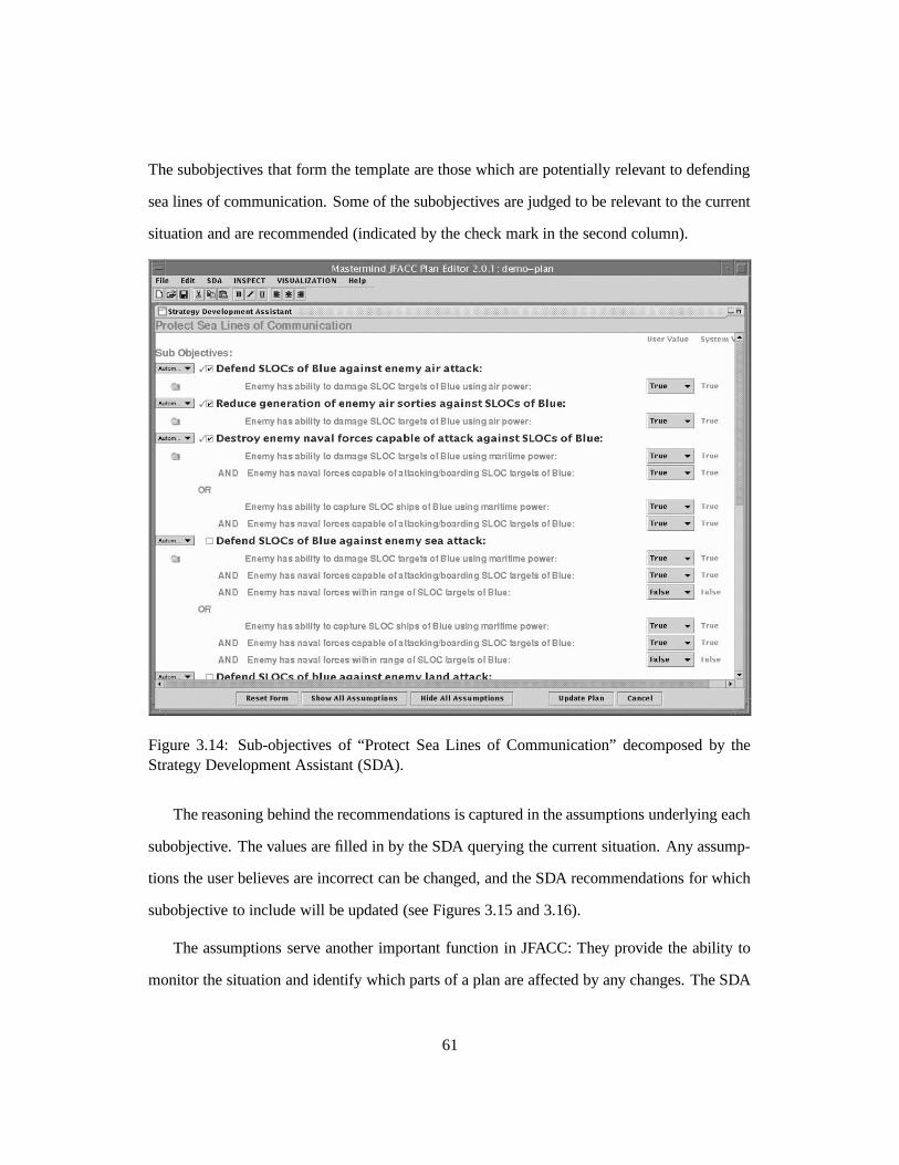
The subobjectives that form the template are those which are potentially relevant to defending
sea lines of communication. Some of the subobjectives are judged to be relevant to the current
situation and are recommended (indicated by the check mark in the second column).
Figure 3.14: Sub-objectives of “Protect Sea Lines of Communication” decomposed by theStrategy Development Assistant (SDA).
The reasoning behind the recommendations is captured in the assumptions underlying each
subobjective. The values are filled in by the SDA querying the current situation. Any assump-
tions the user believes are incorrect can be changed, and the SDA recommendations for which
subobjective to include will be updated (see Figures 3.15 and 3.16).
The assumptions serve another important function in JFACC: They provide the ability to
monitor the situation and identify which parts of a plan are affected by any changes. The SDA
61
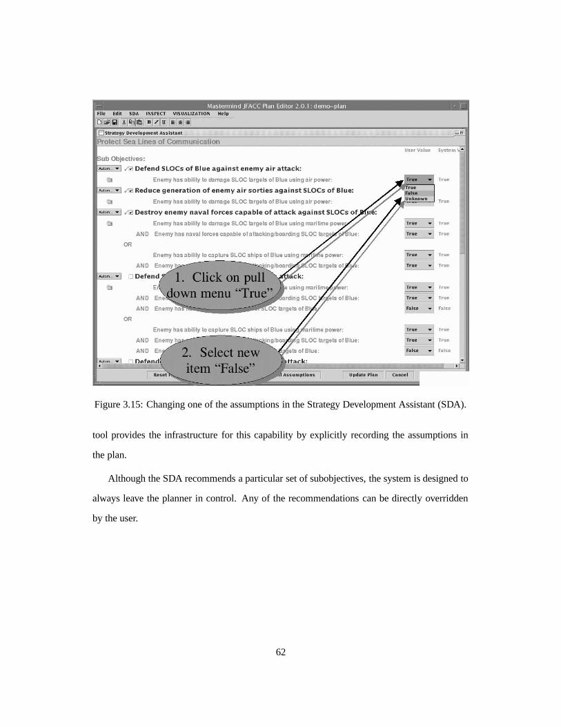
Figure 3.15: Changing one of the assumptions in the Strategy Development Assistant (SDA).
tool provides the infrastructure for this capability by explicitly recording the assumptions in
the plan.
Although the SDA recommends a particular set of subobjectives, the system is designed to
always leave the planner in control. Any of the recommendations can be directly overridden
by the user.
62
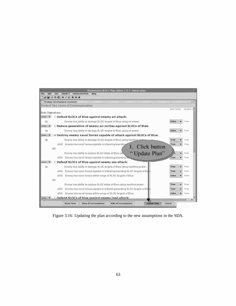
Figure 3.16: Updating the plan according to the new assumptions in the SDA.
63
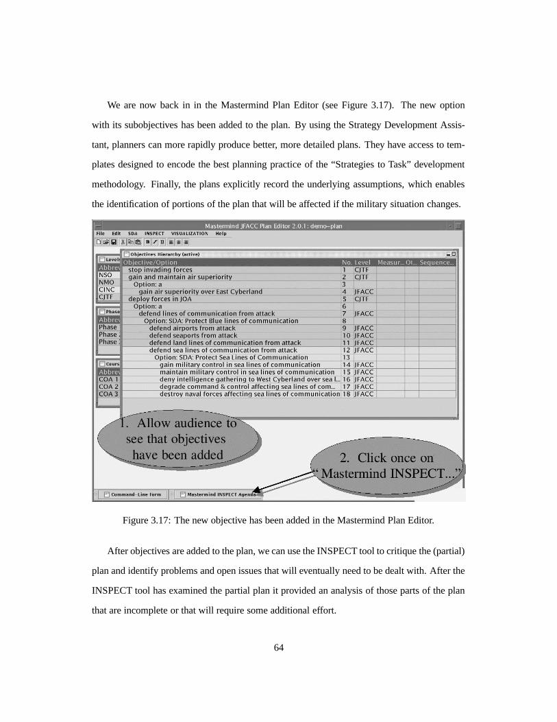
We are now back in in the Mastermind Plan Editor (see Figure 3.17). The new option
with its subobjectives has been added to the plan. By using the Strategy Development Assis-
tant, planners can more rapidly produce better, more detailed plans. They have access to tem-
plates designed to encode the best planning practice of the “Strategies to Task” development
methodology. Finally, the plans explicitly record the underlying assumptions, which enables
the identification of portions of the plan that will be affected if the military situation changes.
Figure 3.17: The new objective has been added in the Mastermind Plan Editor.
After objectives are added to the plan, we can use the INSPECT tool to critique the (partial)
plan and identify problems and open issues that will eventually need to be dealt with. After the
INSPECT tool has examined the partial plan it provided an analysis of those parts of the plan
that are incomplete or that will require some additional effort.
64
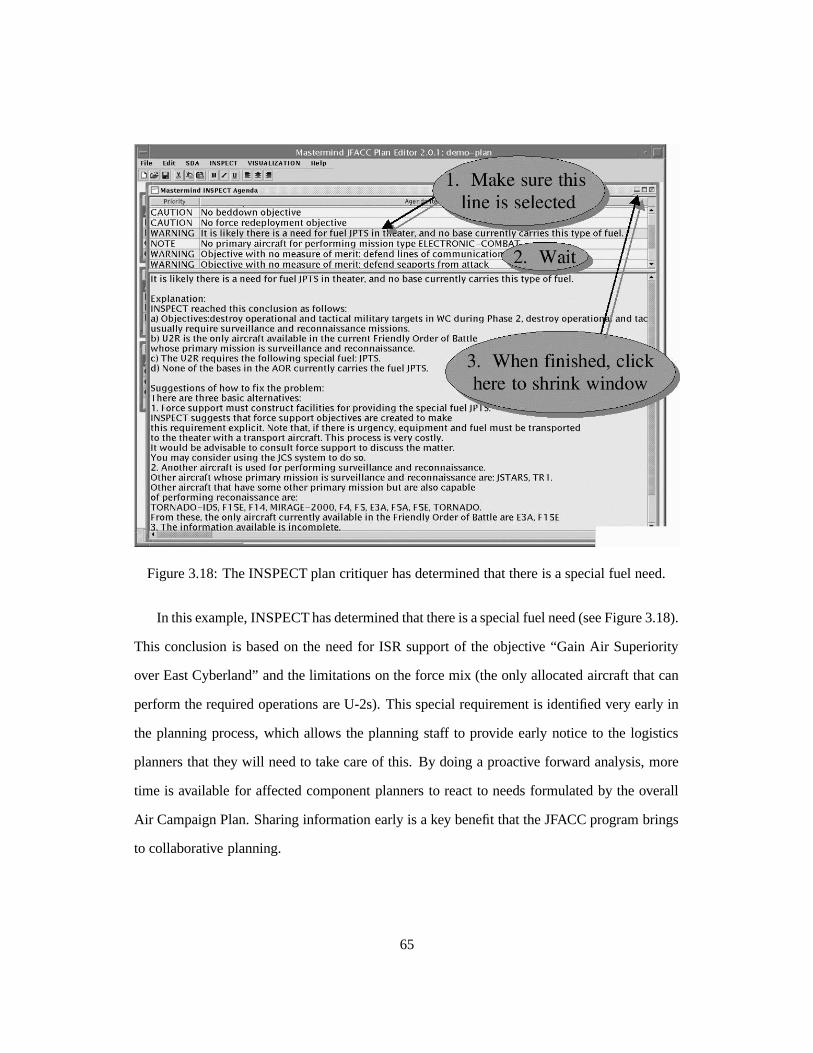
Figure 3.18: The INSPECT plan critiquer has determined that there is a special fuel need.
In this example, INSPECT has determined that there is a special fuel need (see Figure 3.18).
This conclusion is based on the need for ISR support of the objective “Gain Air Superiority
over East Cyberland” and the limitations on the force mix (the only allocated aircraft that can
perform the required operations are U-2s). This special requirement is identified very early in
the planning process, which allows the planning staff to provide early notice to the logistics
planners that they will need to take care of this. By doing a proactive forward analysis, more
time is available for affected component planners to react to needs formulated by the overall
Air Campaign Plan. Sharing information early is a key benefit that the JFACC program brings
to collaborative planning.
65
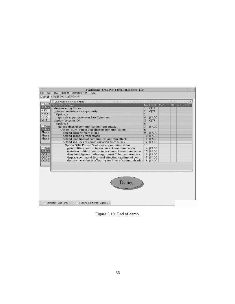
Figure 3.19: End of demo.
66
Bibliography
[1] J. Allen. Towards a general theory of action and time. Artificial Intelligence, 23:123–154,
1984.
[2] R.J. Brachman, D.L. McGuinness, P.F. Patel-Schneider, L. Alperin Resnick, and
A. Borgida. Living with Classic: When and how to use a KL-ONE-like language. In
J.F. Sowa, editor, Principles of Semantic Networks: Explorations in the Representation
of Knowledge, pages 401–456. Morgan Kaufmann, San Mateo, CA, 1991.
[3] H. Chalupsky. OntoMorph: a translation system for symbolic knowledge. In A.G. Cohn,
F. Giunchiglia, and B. Selman, editors, Principles of Knowledge Representation and Rea-
soning: Proceedings of the Seventh International Conference (KR2000), San Francisco,
CA, 2000. Morgan Kaufmann.
[4] C. Fillmore. The case for case. In Universals of Linguistic Theory. Holt, New York, 1968.
[5] M. Frank and P. Szekely. Adaptive forms: An interaction paradigm for entering structured
data. In Proceedings of the ACM International Conference on Intelligent User Interfaces,
pages 153–160, San Francisco, California, January 1998. ACM Press.
[6] T.R. Gruber. A translation approach to portable ontology specifications. Knowledge
Aquisition, 5(2):199–220, 1993.
67
[7] T.R. Gruber. Toward principles for the design of ontologies used for knowledge sharing.
International Journal of Human-Computer Studies, 43(5,6):907–928, 1995.
[8] T. Hama, M. Hori, and Y. Nakamura. Task-specific language constructs for describing
constraints in job assignment problems. Research Report RT0084, IBM, 1992.
[9] D.B. Lenat and R.V. Guha. Building large knowledge-based systems. Representation and
inference in the Cyc project. Addison-Wesley, Reading, Massachusetts, 1990.
[10] R.M. MacGregor. Inside the LOOM description classifier. ACM SIGART Bulletin,
2(3):88–92, 1991.
[11] R.M. MacGregor. A description classifier for the predicate calculus. In Proceedings of
the Twelfth National Conference on Artificial Intelligence, (AAAI 94), pages 213–220,
1994.
[12] D.L. McGuinness, R.E. Fikes, J. Rice, and S. Wilder. An environment for merging and
testing large ontologies. In A.G. Cohn, F. Giunchiglia, and B. Selman, editors, Principles
of Knowledge Representation and Reasoning: Proceedings of the Seventh International
Conference (KR2000), San Francisco, CA, 2000. Morgan Kaufmann.
[13] K.L. Myers. Strategic advice for hierarchical planners. In L. Carlucci Aiello, J. Doyle,
and S.C. Shapiro, editors, Proceedings of the Fifth International Conference on Principles
of Knowledge Representation and Reasoning, pages 112–123, San Francisco, Novem-
ber 5–8 1996. Morgan Kaufmann.
[14] N.F. Noy and M.A. Musen. SMART: Automated support for ontology merging and align-
ment. In Proceedings of the Twelfth Banff Workshop on Knowledge Acquisition, Model-
ing, and Management, Banff, Alberta, Canada, 1999.
68
[15] P.F. Patel-Schneider, B. Owsnicki-Klewe, A. Kobsa, N. Guarino, R. MacGregor, W.S.
Mark, D. MacGuiness, B. Nebel, A. Schmiedel, and J. Yen. Term subsumption languages
in knowledge representation. AI Magazine, 11(2):16–23, 1990.
[16] W. Swartout, R. Patil, K. Knight, and T. Russ. Toward distributed use of large-scale
ontologies. In B. Gaines and M. Musen, editors, Proceedings of the Tenth Knowledge
Acquisition for Knowledge-Based Systems Workshop, 1996.
[17] A. Valente, Y. Gil, and W. Swartout. INSPECT: An intelligent system for air campaign
plan evaluation based on EXPECT. Technical report, USC – Information Sciences Insti-
tute, 1996.
[18] G. Wiederhold and J. Jannink. Composing diverse ontologies. Technical report, Stanford
University, 1998.
[19] W.A. Woods. Understanding subsumption and taxonomy: A framework for progress. In
J.F. Sowa, editor, Principles of Semantic Networks: Explorations in the Representation
of Knowledge, pages 45–94. Morgan Kaufmann, San Mateo, CA, 1991.
69