ONE MORE TIME CD - BMI Gaming · ONE MORE TIME CD 22 To Purchase This Item, Visit BMI Gaming | |...
100
R ONE MORE TIME CD 22 To Purchase This Item, Visit BMI Gaming | www.bmigaming.com | (800) 746-2255 | +1.561.391.7200
Transcript of ONE MORE TIME CD - BMI Gaming · ONE MORE TIME CD 22 To Purchase This Item, Visit BMI Gaming | |...

R
ONE MORE TIME CD
22
To Purchase This Item, Visit BMI Gaming | www.bmigaming.com | (800) 746-2255 | +1.561.391.7200
WARNING! Although the beam emitted by the laser diodes is nearly invisible, it may cause severe damage tothe human eye. Use an infrared indicator to check the laser beam.
ATTENTION! The CD mechanism and many ICs are extremely susceptible to electrostatic discharges. The photo diodesand the laser diode are more sensitive to discharges than MOS ICs. Careless handling may immediately de-stroy components or can drastically reduce life expectancy of these components so that it will lead to failure af-ter several weeks or even months of use.
Before you touch the player, discharge your hands and tools by touching a grounded metal part of the jukebox,such as the amplifier or the mechanism chassis. Make sure that you are connected via a wrist wrap with resis-tance to the same potential as the chassis of the jukebox. Keep parts and tools at the same potential.
If you remove the player in case of repair or for transport, short the harness with a short circuit plug.
When repairing, observe all valid safety rules. Do not change the original condition of the jukebox. Use originalspare parts only.
This manual belongs to machines equipped with program versiones 4.09 (or higher).
Subject to alterations.
CLASS
LASER PRODUCT
1
3122 110 03420
ESD
To Purchase This Item, Visit BMI Gaming | www.bmigaming.com | (800) 746-2255 | +1.561.391.7200

OMT CD – Edition: 09.08.2007 1
1 Unpacking . . . . . . . . . . . . . . . . . . . . . . . . . . . . . . . . . . . . . . . . . . . . . . . . . . . . . . . . 51.1 Unlocking . . . . . . . . . . . . . . . . . . . . . . . . . . . . . . . . . . . . . . . . . . . . . . . . . . . . . . . . . . . . . . . . . . . . . . . . 5
1.2 Removal of mechanism shipping guards . . . . . . . . . . . . . . . . . . . . . . . . . . . . . . . . . . . . . . . . . . . . . . 5
1.3 Removal of motor book shipping guards . . . . . . . . . . . . . . . . . . . . . . . . . . . . . . . . . . . . . . . . . . . . . . 6
1.4 Power on. . . . . . . . . . . . . . . . . . . . . . . . . . . . . . . . . . . . . . . . . . . . . . . . . . . . . . . . . . . . . . . . . . . . . . . . . 6
2 Loading compact discs . . . . . . . . . . . . . . . . . . . . . . . . . . . . . . . . . . . . . . . . . . . . . 72.1 CD handling precautions - CD and player cleaning . . . . . . . . . . . . . . . . . . . . . . . . . . . . . . . . . . . . . . 7
2.2 Inserting CDs . . . . . . . . . . . . . . . . . . . . . . . . . . . . . . . . . . . . . . . . . . . . . . . . . . . . . . . . . . . . . . . . . . . . . 8
2.3 Programming number of CDs in the carrier . . . . . . . . . . . . . . . . . . . . . . . . . . . . . . . . . . . . . . . . . . . . 9
3 Coin operation or free play? . . . . . . . . . . . . . . . . . . . . . . . . . . . . . . . . . . . . . . . . 103.1 Coin operation and coin return . . . . . . . . . . . . . . . . . . . . . . . . . . . . . . . . . . . . . . . . . . . . . . . . . . . . . 10
3.2 Price settings . . . . . . . . . . . . . . . . . . . . . . . . . . . . . . . . . . . . . . . . . . . . . . . . . . . . . . . . . . . . . . . . . . . . 10
3.3 Examples . . . . . . . . . . . . . . . . . . . . . . . . . . . . . . . . . . . . . . . . . . . . . . . . . . . . . . . . . . . . . . . . . . . . . . . 11
3.4 Color codes of coin input . . . . . . . . . . . . . . . . . . . . . . . . . . . . . . . . . . . . . . . . . . . . . . . . . . . . . . . . . . 11
3.5 Free play . . . . . . . . . . . . . . . . . . . . . . . . . . . . . . . . . . . . . . . . . . . . . . . . . . . . . . . . . . . . . . . . . . . . . . . . 12
3.6 Test credit. . . . . . . . . . . . . . . . . . . . . . . . . . . . . . . . . . . . . . . . . . . . . . . . . . . . . . . . . . . . . . . . . . . . . . . 12
4 Track selection . . . . . . . . . . . . . . . . . . . . . . . . . . . . . . . . . . . . . . . . . . . . . . . . . . . 144.1 How to select a track . . . . . . . . . . . . . . . . . . . . . . . . . . . . . . . . . . . . . . . . . . . . . . . . . . . . . . . . . . . . . . 14
4.2 The button R. . . . . . . . . . . . . . . . . . . . . . . . . . . . . . . . . . . . . . . . . . . . . . . . . . . . . . . . . . . . . . . . . . . . . 14
4.3 The display flashes . . . . . . . . . . . . . . . . . . . . . . . . . . . . . . . . . . . . . . . . . . . . . . . . . . . . . . . . . . . . . . . 14
4.4 I do not like this track - the button CANCEL . . . . . . . . . . . . . . . . . . . . . . . . . . . . . . . . . . . . . . . . . . . 15
5 Volume, sound and balance control . . . . . . . . . . . . . . . . . . . . . . . . . . . . . . . . . . 165.1 Volume, sound and balance control - amplifier K99 . . . . . . . . . . . . . . . . . . . . . . . . . . . . . . . . . . . . 165.1.1 The infrared remote control . . . . . . . . . . . . . . . . . . . . . . . . . . . . . . . . . . . . . . . . . . . . . . . . . . . . . . . . . . 17
5.2 Volume, sound and balance control - amplifier F91. . . . . . . . . . . . . . . . . . . . . . . . . . . . . . . . . . . . . 185.2.1 The infrared remote control . . . . . . . . . . . . . . . . . . . . . . . . . . . . . . . . . . . . . . . . . . . . . . . . . . . . . . . . . . 19
5.3 Pre-settings for volume. . . . . . . . . . . . . . . . . . . . . . . . . . . . . . . . . . . . . . . . . . . . . . . . . . . . . . . . . . . . 205.3.1 Pre-settings for bass and treble. . . . . . . . . . . . . . . . . . . . . . . . . . . . . . . . . . . . . . . . . . . . . . . . . . . . . . . 20
6 Programming short view . . . . . . . . . . . . . . . . . . . . . . . . . . . . . . . . . . . . . . . . . . . 21
7 Jukebox programming . . . . . . . . . . . . . . . . . . . . . . . . . . . . . . . . . . . . . . . . . . . . . 227.1 Call up service programs . . . . . . . . . . . . . . . . . . . . . . . . . . . . . . . . . . . . . . . . . . . . . . . . . . . . . . . . . . 22
7.2 How to leave service programs . . . . . . . . . . . . . . . . . . . . . . . . . . . . . . . . . . . . . . . . . . . . . . . . . . . . . 22
7.3 Programming of time functions . . . . . . . . . . . . . . . . . . . . . . . . . . . . . . . . . . . . . . . . . . . . . . . . . . . . . 237.3.1 Clock setting, level 2 button 0 . . . . . . . . . . . . . . . . . . . . . . . . . . . . . . . . . . . . . . . . . . . . . . . . . . . . . . . . 237.3.2 Set date, level 2 button 1 . . . . . . . . . . . . . . . . . . . . . . . . . . . . . . . . . . . . . . . . . . . . . . . . . . . . . . . . . . . . 237.3.3 Set year and weekday, level 2 button 2. . . . . . . . . . . . . . . . . . . . . . . . . . . . . . . . . . . . . . . . . . . . . . . . . 23
7.4 Automatic random select (Playstimulator) . . . . . . . . . . . . . . . . . . . . . . . . . . . . . . . . . . . . . . . . . . . . 247.4.1 Programming start and stop time. . . . . . . . . . . . . . . . . . . . . . . . . . . . . . . . . . . . . . . . . . . . . . . . . . . . . . 25
7.5 Back Ground Music (BGM) . . . . . . . . . . . . . . . . . . . . . . . . . . . . . . . . . . . . . . . . . . . . . . . . . . . . . . . . . 267.5.1 Number of BGM CDs and repeat time. . . . . . . . . . . . . . . . . . . . . . . . . . . . . . . . . . . . . . . . . . . . . . . . . . 277.5.2 Start position for BGM CDs and configuration. . . . . . . . . . . . . . . . . . . . . . . . . . . . . . . . . . . . . . . . . . . . 287.5.3 BGM time zones at different weekdays . . . . . . . . . . . . . . . . . . . . . . . . . . . . . . . . . . . . . . . . . . . . . . . . . 28
7.6 HappyHour pricing (additional bonus plays) . . . . . . . . . . . . . . . . . . . . . . . . . . . . . . . . . . . . . . . . . . 307.6.1 Programming of the HappyHour start and stop time, level 2 button 6 . . . . . . . . . . . . . . . . . . . . . . . . . . 30
To Purchase This Item, Visit BMI Gaming | www.bmigaming.com | (800) 746-2255 | +1.561.391.7200

OMT CD – Edition: 09.08.20072
7.6.2 Programming of the additional bonus plays, level 2 button 7 . . . . . . . . . . . . . . . . . . . . . . . . . . . . . . . . 30
7.7 Number of tracks played successively on the same disc, level 2 button 3. . . . . . . . . . . . . . . . . . 31
7.8 Album selection and memory reset by power off, level 2 button 9 . . . . . . . . . . . . . . . . . . . . . . . . 32
7.9 Disabling single tracks . . . . . . . . . . . . . . . . . . . . . . . . . . . . . . . . . . . . . . . . . . . . . . . . . . . . . . . . . . . . 33
8 Data retrieval . . . . . . . . . . . . . . . . . . . . . . . . . . . . . . . . . . . . . . . . . . . . . . . . . . . . . 348.1 Retrieval of least popular discs (flops), level 1 button 0 . . . . . . . . . . . . . . . . . . . . . . . . . . . . . . . . . 34
8.2 Top Tunes, level 1 button 1 . . . . . . . . . . . . . . . . . . . . . . . . . . . . . . . . . . . . . . . . . . . . . . . . . . . . . . . . 34
8.3 Cash box contents, level 1 button 2 . . . . . . . . . . . . . . . . . . . . . . . . . . . . . . . . . . . . . . . . . . . . . . . . . 35
8.4 Total number of plays, level 1 button 3. . . . . . . . . . . . . . . . . . . . . . . . . . . . . . . . . . . . . . . . . . . . . . . 35
8.5 CLEAR ALL counters (reset to 0 0 0 0), level 1 button 3 + reset. . . . . . . . . . . . . . . . . . . . . . . . . . . 35
8.6 Memory of not playable CDs, level 1 button 6 . . . . . . . . . . . . . . . . . . . . . . . . . . . . . . . . . . . . . . . . . 35
9 Amplifier K99 . . . . . . . . . . . . . . . . . . . . . . . . . . . . . . . . . . . . . . . . . . . . . . . . . . . . . 369.1 Device description of the amplifier K99 . . . . . . . . . . . . . . . . . . . . . . . . . . . . . . . . . . . . . . . . . . . . . . 36
9.2 Technical data . . . . . . . . . . . . . . . . . . . . . . . . . . . . . . . . . . . . . . . . . . . . . . . . . . . . . . . . . . . . . . . . . . . 36
9.3 Verification of power voltage . . . . . . . . . . . . . . . . . . . . . . . . . . . . . . . . . . . . . . . . . . . . . . . . . . . . . . . 37
9.4 Position of fuses and plug connectors . . . . . . . . . . . . . . . . . . . . . . . . . . . . . . . . . . . . . . . . . . . . . . . 38
9.5 The first power ON . . . . . . . . . . . . . . . . . . . . . . . . . . . . . . . . . . . . . . . . . . . . . . . . . . . . . . . . . . . . . . . 39
9.6 Volume control . . . . . . . . . . . . . . . . . . . . . . . . . . . . . . . . . . . . . . . . . . . . . . . . . . . . . . . . . . . . . . . . . . 39
9.7 The infrared remote control . . . . . . . . . . . . . . . . . . . . . . . . . . . . . . . . . . . . . . . . . . . . . . . . . . . . . . . . 40
9.8 Treble and bass control . . . . . . . . . . . . . . . . . . . . . . . . . . . . . . . . . . . . . . . . . . . . . . . . . . . . . . . . . . . 41
9.9 Automatic volume correction. . . . . . . . . . . . . . . . . . . . . . . . . . . . . . . . . . . . . . . . . . . . . . . . . . . . . . . 41
9.10 Background Music - volume attenuation . . . . . . . . . . . . . . . . . . . . . . . . . . . . . . . . . . . . . . . . . . . . . 41
9.11 External speaker connection . . . . . . . . . . . . . . . . . . . . . . . . . . . . . . . . . . . . . . . . . . . . . . . . . . . . . . . 42
9.12 External amplifier connection . . . . . . . . . . . . . . . . . . . . . . . . . . . . . . . . . . . . . . . . . . . . . . . . . . . . . . 43
9.13 Disabling the internal mute circuit . . . . . . . . . . . . . . . . . . . . . . . . . . . . . . . . . . . . . . . . . . . . . . . . . . 43
9.14 Input selector. . . . . . . . . . . . . . . . . . . . . . . . . . . . . . . . . . . . . . . . . . . . . . . . . . . . . . . . . . . . . . . . . . . . 43
10 Amplifier F91 . . . . . . . . . . . . . . . . . . . . . . . . . . . . . . . . . . . . . . . . . . . . . . . . . . . . . 4410.1 Verification of power voltage . . . . . . . . . . . . . . . . . . . . . . . . . . . . . . . . . . . . . . . . . . . . . . . . . . . . . . . 44
10.2 Position of fuses and plug connectors on the power amp board . . . . . . . . . . . . . . . . . . . . . . . . . 45
10.3 The first power ON . . . . . . . . . . . . . . . . . . . . . . . . . . . . . . . . . . . . . . . . . . . . . . . . . . . . . . . . . . . . . . . 46
10.4 Pre-settings for volume, bass, treble . . . . . . . . . . . . . . . . . . . . . . . . . . . . . . . . . . . . . . . . . . . . . . . . 4610.4.1 Pre-settings for volume . . . . . . . . . . . . . . . . . . . . . . . . . . . . . . . . . . . . . . . . . . . . . . . . . . . . . . . . . . . . . 4710.4.2 Pre-settings for bass and treble . . . . . . . . . . . . . . . . . . . . . . . . . . . . . . . . . . . . . . . . . . . . . . . . . . . . . . 47
10.5 Speaker connections . . . . . . . . . . . . . . . . . . . . . . . . . . . . . . . . . . . . . . . . . . . . . . . . . . . . . . . . . . . . . 4810.5.1 The operating mode STEREO . . . . . . . . . . . . . . . . . . . . . . . . . . . . . . . . . . . . . . . . . . . . . . . . . . . . . . . 49
10.6 Connecting external speakers in operating mode 2-CHANNEL . . . . . . . . . . . . . . . . . . . . . . . . . . . 50
10.7 BGM mode - volume attenuation . . . . . . . . . . . . . . . . . . . . . . . . . . . . . . . . . . . . . . . . . . . . . . . . . . . . 51
10.8 Automatic volume control (AVC) and clipping stage. . . . . . . . . . . . . . . . . . . . . . . . . . . . . . . . . . . . 51
10.9 Overdrive protection . . . . . . . . . . . . . . . . . . . . . . . . . . . . . . . . . . . . . . . . . . . . . . . . . . . . . . . . . . . . . . 51
10.10 Overload protection . . . . . . . . . . . . . . . . . . . . . . . . . . . . . . . . . . . . . . . . . . . . . . . . . . . . . . . . . . . . . . 52
10.11 Tape input . . . . . . . . . . . . . . . . . . . . . . . . . . . . . . . . . . . . . . . . . . . . . . . . . . . . . . . . . . . . . . . . . . . . . . 52
11 70v output transformer (0043157) . . . . . . . . . . . . . . . . . . . . . . . . . . . . . . . . . . . . 5311.1 Hints of connectable speaker loads . . . . . . . . . . . . . . . . . . . . . . . . . . . . . . . . . . . . . . . . . . . . . . . . . 53
To Purchase This Item, Visit BMI Gaming | www.bmigaming.com | (800) 746-2255 | +1.561.391.7200

OMT CD – Edition: 09.08.2007 3
11.2 Determination of the connectable speaker power . . . . . . . . . . . . . . . . . . . . . . . . . . . . . . . . . . . . . . 54
11.3 Hints for speaker connection . . . . . . . . . . . . . . . . . . . . . . . . . . . . . . . . . . . . . . . . . . . . . . . . . . . . . . . 54
11.4 Connection of 70v systems . . . . . . . . . . . . . . . . . . . . . . . . . . . . . . . . . . . . . . . . . . . . . . . . . . . . . . . . 55
12 Amplifier I84 . . . . . . . . . . . . . . . . . . . . . . . . . . . . . . . . . . . . . . . . . . . . . . . . . . . . . 5612.1 Fuses . . . . . . . . . . . . . . . . . . . . . . . . . . . . . . . . . . . . . . . . . . . . . . . . . . . . . . . . . . . . . . . . . . . . . . . . . . 56
12.2 Volume control. . . . . . . . . . . . . . . . . . . . . . . . . . . . . . . . . . . . . . . . . . . . . . . . . . . . . . . . . . . . . . . . . . . 57
12.3 Automatic loudness controller. . . . . . . . . . . . . . . . . . . . . . . . . . . . . . . . . . . . . . . . . . . . . . . . . . . . . . 57
12.4 Treble and bass control . . . . . . . . . . . . . . . . . . . . . . . . . . . . . . . . . . . . . . . . . . . . . . . . . . . . . . . . . . . 57
12.5 Slide switch ’Stereo/2-Kanal’ . . . . . . . . . . . . . . . . . . . . . . . . . . . . . . . . . . . . . . . . . . . . . . . . . . . . . . . 57
12.6 Maximum amplifier load and external speakers . . . . . . . . . . . . . . . . . . . . . . . . . . . . . . . . . . . . . . . . 58
12.7 Connection of external speakers . . . . . . . . . . . . . . . . . . . . . . . . . . . . . . . . . . . . . . . . . . . . . . . . . . . . 58
12.8 Infrared remote control . . . . . . . . . . . . . . . . . . . . . . . . . . . . . . . . . . . . . . . . . . . . . . . . . . . . . . . . . . . . 59
12.9 Infrared remote control with selection buttons . . . . . . . . . . . . . . . . . . . . . . . . . . . . . . . . . . . . . . . . 60
13 Function tests . . . . . . . . . . . . . . . . . . . . . . . . . . . . . . . . . . . . . . . . . . . . . . . . . . . . 6113.1 Digital display test / EPROM-version, level 1 button 4. . . . . . . . . . . . . . . . . . . . . . . . . . . . . . . . . . . 61
13.2 CD carrier control check, level 1, button 8 . . . . . . . . . . . . . . . . . . . . . . . . . . . . . . . . . . . . . . . . . . . . 61
13.3 Gripper arm motor test, level 1, button 7 . . . . . . . . . . . . . . . . . . . . . . . . . . . . . . . . . . . . . . . . . . . . . 61
13.4 CD player check (START), level 1, button 6 . . . . . . . . . . . . . . . . . . . . . . . . . . . . . . . . . . . . . . . . . . . 62
13.5 Jump to NEXT track, level 1, button 0 . . . . . . . . . . . . . . . . . . . . . . . . . . . . . . . . . . . . . . . . . . . . . . . . 62
13.6 Jump to PREVIOUS track, level 1, button 9 . . . . . . . . . . . . . . . . . . . . . . . . . . . . . . . . . . . . . . . . . . . 62
13.7 STOP playing, level 1, button 5 . . . . . . . . . . . . . . . . . . . . . . . . . . . . . . . . . . . . . . . . . . . . . . . . . . . . . 63
14 Description of S&CC price setting . . . . . . . . . . . . . . . . . . . . . . . . . . . . . . . . . . . 64
15 Integrated test program of the CD-PRO player . . . . . . . . . . . . . . . . . . . . . . . . . 6515.1 Access to the player functions without S&CC unit . . . . . . . . . . . . . . . . . . . . . . . . . . . . . . . . . . . . . 65
15.2 Test functions CD-PRO . . . . . . . . . . . . . . . . . . . . . . . . . . . . . . . . . . . . . . . . . . . . . . . . . . . . . . . . . . . . 66
15.3 Special test functions of the CD-PRO player . . . . . . . . . . . . . . . . . . . . . . . . . . . . . . . . . . . . . . . . . . 67
16 Functional description of the mechanism . . . . . . . . . . . . . . . . . . . . . . . . . . . . . 6816.1 Abbreviations. . . . . . . . . . . . . . . . . . . . . . . . . . . . . . . . . . . . . . . . . . . . . . . . . . . . . . . . . . . . . . . . . . . . 68
16.2 Functional description . . . . . . . . . . . . . . . . . . . . . . . . . . . . . . . . . . . . . . . . . . . . . . . . . . . . . . . . . . . . 6816.2.1 Power supply . . . . . . . . . . . . . . . . . . . . . . . . . . . . . . . . . . . . . . . . . . . . . . . . . . . . . . . . . . . . . . . . . . . . . 6816.2.2 S&CC supply . . . . . . . . . . . . . . . . . . . . . . . . . . . . . . . . . . . . . . . . . . . . . . . . . . . . . . . . . . . . . . . . . . . . . 6816.2.3 CD-PRO supply . . . . . . . . . . . . . . . . . . . . . . . . . . . . . . . . . . . . . . . . . . . . . . . . . . . . . . . . . . . . . . . . . . . 6816.2.4 Digital display. . . . . . . . . . . . . . . . . . . . . . . . . . . . . . . . . . . . . . . . . . . . . . . . . . . . . . . . . . . . . . . . . . . . . 6816.2.5 Number of plays and cash counter . . . . . . . . . . . . . . . . . . . . . . . . . . . . . . . . . . . . . . . . . . . . . . . . . . . . 6916.2.6 Selection and CD carrier . . . . . . . . . . . . . . . . . . . . . . . . . . . . . . . . . . . . . . . . . . . . . . . . . . . . . . . . . . . . 6916.2.7 Start / counting process . . . . . . . . . . . . . . . . . . . . . . . . . . . . . . . . . . . . . . . . . . . . . . . . . . . . . . . . . . . . . 6916.2.8 CD transfer . . . . . . . . . . . . . . . . . . . . . . . . . . . . . . . . . . . . . . . . . . . . . . . . . . . . . . . . . . . . . . . . . . . . . . 6916.2.9 Mute off . . . . . . . . . . . . . . . . . . . . . . . . . . . . . . . . . . . . . . . . . . . . . . . . . . . . . . . . . . . . . . . . . . . . . . . . . 6916.2.10 Play . . . . . . . . . . . . . . . . . . . . . . . . . . . . . . . . . . . . . . . . . . . . . . . . . . . . . . . . . . . . . . . . . . . . . . . . . . . . 6916.2.11 Cancel . . . . . . . . . . . . . . . . . . . . . . . . . . . . . . . . . . . . . . . . . . . . . . . . . . . . . . . . . . . . . . . . . . . . . . . . . . 6916.2.12 CD return . . . . . . . . . . . . . . . . . . . . . . . . . . . . . . . . . . . . . . . . . . . . . . . . . . . . . . . . . . . . . . . . . . . . . . . . 7016.2.13 New selection . . . . . . . . . . . . . . . . . . . . . . . . . . . . . . . . . . . . . . . . . . . . . . . . . . . . . . . . . . . . . . . . . . . . 70
17 Error messages and remedy . . . . . . . . . . . . . . . . . . . . . . . . . . . . . . . . . . . . . . . . 7017.1 Failures with illumination, display and power system generally . . . . . . . . . . . . . . . . . . . . . . . . . . 71
To Purchase This Item, Visit BMI Gaming | www.bmigaming.com | (800) 746-2255 | +1.561.391.7200

OMT CD – Edition: 09.08.20074
17.2 Faults with the coin system . . . . . . . . . . . . . . . . . . . . . . . . . . . . . . . . . . . . . . . . . . . . . . . . . . . . . . . . 72
17.3 Faults by selection entry . . . . . . . . . . . . . . . . . . . . . . . . . . . . . . . . . . . . . . . . . . . . . . . . . . . . . . . . . . 73
17.4 Repetitive apply of selected or non-selected CDs to turntable . . . . . . . . . . . . . . . . . . . . . . . . . . . 75
17.5 Failures in the system carrier - gripper arm . . . . . . . . . . . . . . . . . . . . . . . . . . . . . . . . . . . . . . . . . . . 75
17.6 Failures with sound reproduction . . . . . . . . . . . . . . . . . . . . . . . . . . . . . . . . . . . . . . . . . . . . . . . . . . . 77
17.7 CD not properly returned to carrier . . . . . . . . . . . . . . . . . . . . . . . . . . . . . . . . . . . . . . . . . . . . . . . . . . 77
18 Accessories . . . . . . . . . . . . . . . . . . . . . . . . . . . . . . . . . . . . . . . . . . . . . . . . . . . . . . 7818.1 Microfone kit (part no. 0006953) . . . . . . . . . . . . . . . . . . . . . . . . . . . . . . . . . . . . . . . . . . . . . . . . . . . . 78
18.2 BGM-Connector . . . . . . . . . . . . . . . . . . . . . . . . . . . . . . . . . . . . . . . . . . . . . . . . . . . . . . . . . . . . . . . . . . 78
19 Wiring and connection diagrams. . . . . . . . . . . . . . . . . . . . . . . . . . . . . . . . . . . . . 7919.1 Wiring diagram door - illumination . . . . . . . . . . . . . . . . . . . . . . . . . . . . . . . . . . . . . . . . . . . . . . . . . . 79
19.2 Connection diagram OMT CD . . . . . . . . . . . . . . . . . . . . . . . . . . . . . . . . . . . . . . . . . . . . . . . . . . . . . . 80
19.3 Board layout Selection & Credit Computer. . . . . . . . . . . . . . . . . . . . . . . . . . . . . . . . . . . . . . . . . . . . 81
19.4 Wiring diagram Selection & Credit Computer . . . . . . . . . . . . . . . . . . . . . . . . . . . . . . . . . . . . . . . . . 82
19.5 Board layout CDM12 SC . . . . . . . . . . . . . . . . . . . . . . . . . . . . . . . . . . . . . . . . . . . . . . . . . . . . . . . . . . . 83
19.6 Wiring diagram CDM12 SC . . . . . . . . . . . . . . . . . . . . . . . . . . . . . . . . . . . . . . . . . . . . . . . . . . . . . . . . . 84
19.7 Wiring diagram 24V distributor interface . . . . . . . . . . . . . . . . . . . . . . . . . . . . . . . . . . . . . . . . . . . . . 85
19.8 Wiring diagram motor page system . . . . . . . . . . . . . . . . . . . . . . . . . . . . . . . . . . . . . . . . . . . . . . . . . 86
19.9 Wiring diagram bubble tubes. . . . . . . . . . . . . . . . . . . . . . . . . . . . . . . . . . . . . . . . . . . . . . . . . . . . . . . 87
19.10 Wiring diagram K99 - power supply . . . . . . . . . . . . . . . . . . . . . . . . . . . . . . . . . . . . . . . . . . . . . . . . . 88
19.11 Wiring diagram K99 - output transformer . . . . . . . . . . . . . . . . . . . . . . . . . . . . . . . . . . . . . . . . . . . . . 89
19.12 Wiring diagram K99 - pre-amplifier . . . . . . . . . . . . . . . . . . . . . . . . . . . . . . . . . . . . . . . . . . . . . . . . . . 90
19.13 Wiring diagram K99 - sound control . . . . . . . . . . . . . . . . . . . . . . . . . . . . . . . . . . . . . . . . . . . . . . . . . 91
19.14 Wiring diagram K99 - port A. . . . . . . . . . . . . . . . . . . . . . . . . . . . . . . . . . . . . . . . . . . . . . . . . . . . . . . . 92
19.15 Wiring diagram K99 - Mute . . . . . . . . . . . . . . . . . . . . . . . . . . . . . . . . . . . . . . . . . . . . . . . . . . . . . . . . 93
19.16 Wiring diagram K99 - power supply Euro 230V . . . . . . . . . . . . . . . . . . . . . . . . . . . . . . . . . . . . . . . . 94
19.17 Wiring diagram K99 - power supply UL/USA 117V. . . . . . . . . . . . . . . . . . . . . . . . . . . . . . . . . . . . . . 95
20 Declaration of Conformity . . . . . . . . . . . . . . . . . . . . . . . . . . . . . . . . . . . . . . . . . . 96
To Purchase This Item, Visit BMI Gaming | www.bmigaming.com | (800) 746-2255 | +1.561.391.7200

Unlocking
OMT CD – Edition: 09.08.2007 5
OP
ER
ATI
NG
INS
TRU
CTI
ON
S
1 Unpacking
1.1 Unlocking
The key is stored in the coin return cup in theRH cabinet wall. The key WUA 1 unlocks thecabinet by turning the key clockwise. The lock isspring loaded, press slightly against the door,this allows the key to turn easily. The two otherkeys with 5 digit number codes unlock the cashbox at the bottom of the RH cabinet wall. In thisbox the hand transmitter is located if an infraredremote control has been installed.
1.2 Removal of mechanism shipping guards
1. The mechanism platform is fixed to cabinetwith one bolt in front LH side (1) and onebolt back RH side (1). Remove both com-pletely using a 13mm spanner or a largescrew driver. Possibly you can use the toolfixed to the lid of the gear box (2).
2. Remove plastic string at the pivot point ofthe pressure arm (3).
3. Remove plastic holder securing CD playerchassis (4).
4. Remove foam (5), laser cover (6) securinglaser head in CD player and instructionplate (7).
5. Remove foam between magnetic pressuredisc and black plastic cover (8).
WUA 1WUA 1456734
WUA 1WUA 1
RCS-KNo.: 0059745
SELECTION1
2
34
5
6RESET
POWER
OPTION
7
8
9
0
-
+
-
+CANCEL
MUTE
MUSIC
INTERNCHANNEL 1
EXTERNCHANNEL 2
WUA 1for door
for cash box
1
1
2 3
4
5
7
8
6
To Purchase This Item, Visit BMI Gaming | www.bmigaming.com | (800) 746-2255 | +1.561.391.7200

Removal of motor book shipping guards
OMT CD – Edition: 09.08.20076
OP
ER
ATIN
G IN
STR
UC
TION
S
1.3 Removal of motor book shipping guards
Cut both plastic strings on both sides of thebook (1).
Press push buttons (2) inside and turn down thebook (3).
Remove elastic band from the motor book sys-tems (4).
NOTE: Save the removed shipping guards. Youmay need them if you decide to move your ma-chine to another location.
1.4 Power on
NOTE: Make sure that wall socket is groundedproperly.
The CD-jukebox operates on normal householdpower outlet. Set mains switch at rear wall of ca-binet to on position. If the selection and creditmemory is empty the basket turns once and theleft two digits show alternatly a "0". After a shorttime the display counts up to the carrier size inthe two RH digits (50 or 00 for 100 discs). Afterthis the basket stops in position "01". The digitaldisplay shows "0 0 0 0", then "0 0 0 1" when abasket with 100 CDs is used "0 1 0 1" for a 50CD carrier.
11
22
334
4
?o.k.
power switch
To Purchase This Item, Visit BMI Gaming | www.bmigaming.com | (800) 746-2255 | +1.561.391.7200

CD handling precautions - CD and player cleaning
OMT CD – Edition: 09.08.2007 7
OP
ER
ATI
NG
INS
TRU
CTI
ON
S
2 Loading compact discs
2.1 CD handling precautions - CD and player cleaning
Dust, fingerprints or other dirt on the disc surface cancause skipping, jumping or sticking problems.
Because of this never touch the surface of a disc! Howe-ver it is rather easy to remove nicotine, dust or finger-prints.
Nicotine, dust, fingerprints:Dust can be removed with a lintfree soft cloth. If neces-sary, remove heavy dirt or fingerprints with a moistenedsoft cloth soaked in a solution of water and a detergent.Never use record cleaning sprays or anti static sprays!Furthermore, do not use other types of cleaners contai-ning benzene, thinner or other solvents. These liquids willcause damage to the surface of discs. Move the clothfrom the inside towards the outside and not in circularmotion.
Removing scratches:Use a soft cloth and a soft polish.
Laser lens cleaning:Smoke and dust soils the lens. It can be cleaned with acue-tip soaked in a detergent (i.e. Kodak Lens Cleaner,part no. 0051735). Place the tip on the lens and pressdown carefully.
ATTENTION! The whole laser unit is very sensitive!
! Move the cue-tip only in the direction shown in the pic-ture (perp. to the sledge direction).
! Do not scratch the special treated surface of thelense.
! Take care that the cleaning solution will not run intothe focus unit.
! Keep away metal parts from the lens unit. A strong magnet is located underneath the lens. It at-tracts also smallest metal parts and so can block the complete unit.
To Purchase This Item, Visit BMI Gaming | www.bmigaming.com | (800) 746-2255 | +1.561.391.7200
Inserting CDs
OMT CD – Edition: 09.08.20078
OP
ER
ATIN
G IN
STR
UC
TION
S
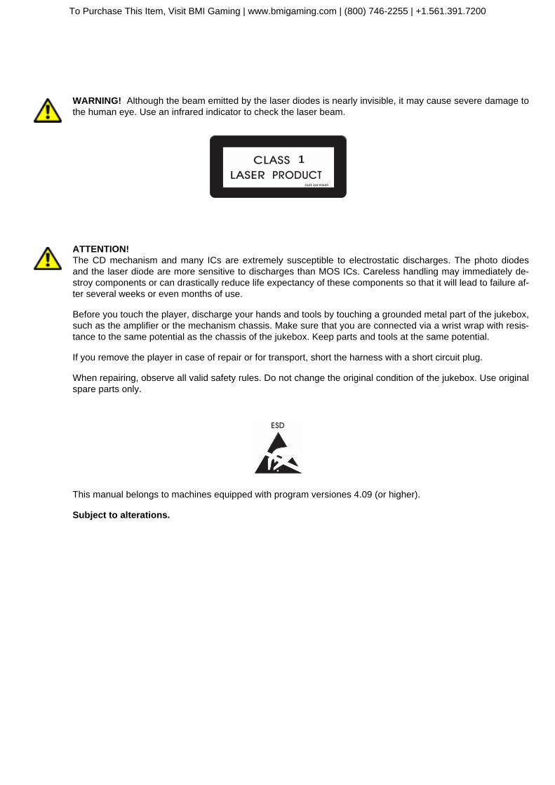
2.2 Inserting CDs
Insert up to 50 or 100 CDs, depending on thecompartments in the carrier. Start with 01. The"Label" must show always to the left, towardsthe next lower number. To achieve the optimumposition for loading, press in steps the lever "ro-tate carrier". If less than 50 (100) discs areused, the number of discs used has to be pro-grammed in the service program level 1, button5 (see chapter "Programming number of CDs inthe carrier", see page 9).
ATTENTION! For carriers with 100 CDs the po-sition ’00’ is the 100th CD.
It is recommended to insert the Compact Discand then the title page into the appropriate nu-merical slot position of the motor page system.The pages can be turned manually by hand wit-hout any damage to the motor drive. In somemodels the transparent dust cover of the recordcarrier has to be lifted up at the front, it will restin this position.
NOTE: After unpacking or if you turned the pa-ges manually sometimes it seems that the mo-torbook does not turn properly. In this case turnthe whole motorbook once forward and back-ward using the buttons.
It is necessary to reprogramme the number ofCDs in the carrier if a number less than 50 or100 discs are inserted to avoid the changer me-chanism operating with empty compartments.
If the number of CDs is programmed correctlythe display will flash when you select an emptycompartment. A flashing display always indica-tes a wrong selection or not enough credit.
The number of CDs in the carrier has to be pro-grammed in service level 1, selection button 5,described as follows.
01
lever
1 23 45 67 89 0
R
buttonsto turn themotor book
To Purchase This Item, Visit BMI Gaming | www.bmigaming.com | (800) 746-2255 | +1.561.391.7200

Programming number of CDs in the carrier
OMT CD – Edition: 09.08.2007 9
OP
ER
ATI
NG
INS
TRU
CTI
ON
S
2.3 Programming number of CDs in the carrier
At the rear wall inside the jukebox cabinet the Selection &Credit Computer is situated. Some units are equippedwith a metal cover. In this case the slide switch "SER-VICE" and the button "LT" are accessible through holes.
To programme the number of inserted CDs (service pro-gram, level 1):
1. Set the slide switch ‘service’ at the SCC-unit to ON.
2. Press ‘LT’ button.
3. Press selection button 5 -hold down- and press se-lection button R than release both buttons.
4. Enter the number of inserted CDs (without BGMCDs) with two digits followed by 00, example: 50 for50 discs (exception: 100. CDs = 00).
To check the new settings, press selection button 5again.
Exit the service program:
1. Set the slide switch ‘service’ at the SCC unit to OFF.
2. Press ‘LT’ button.
" The changer starts an initialisation run. After this thejukebox is ready to operate.
Selection &
Credit Computer
CDM 12
CD Tower
Netzsicherung
Mains FuseNetzsicherung
Mains Fuse
210-240V - T 4A
100-117V - F 6A210-240V - T 4A
100-117V - F 6A
Leuchtstofflampen
Fluorescent Lamps
230V / 117V
Leuchtstofflampen
Fluorescent Lamps
230V / 117V
Vers
tärk
er
Am
plif
ier
Vers
tärk
er
Am
plif
ier
Externer Hauptschalter
External Mains switchExterner Hauptschalter
External Mains switch
Schein-
annehmer
Bill-
acceptor
Schein-
annehmer
Bill-
acceptor
Achtung!
Vor Abnahme der Kappe den Netzstecker
ziehen!
Achtung!
Vor Abnahme der Kappe den Netzstecker
ziehen!
Warning!
Shock hazard! Do not open!Warning!
Shock hazard! Do not open!
Zur Beachtung: Nur Sicherungen mit
gleicher Größe und gleichem Wert
verwenden, um Schäden zu vermeiden.
Caution: To reduce the risk of fire
replace only with same typ and rating fuses.
Zur Beachtung: Nur Sicherungen mit
gleicher Größe und gleichem Wert
verwenden, um Schäden zu vermeiden.
Caution: To reduce the risk of fire
replace only with same typ and rating fuses.
Netzspannung
50/60 Hz
Mains Voltage
50/60 cps
Netzspannung
50/60 Hz
Mains Voltage
50/60 cps
240230220210117100
240230220210117100
CAUTIONCAUTIONTO REDUCE THE RISK
OF FIRE REPLACE ONLY
WITH SAME TYPE AND
RATING FUSE
TO REDUCE THE RISK
OF FIRE REPLACE ONLY
WITH SAME TYPE AND
RATING FUSEBassBass TrebleTreble BGMBGM
M
S
ONO
TEREO
M
S
ONO
TEREO
ANAL HANNEL
TEREO
2-K / 2-C
S
ANAL HANNEL
TEREO
2-K / 2-C
S
SF
ICHERUNG
USESF
ICHERUNG
USEF1 - F4F1 - F4
100-240 V50Hz/60Hz100-240 V50Hz/60Hz
117 V60Hz117 V60Hz
3,0 AMP250 V ACSLOW BLOW
3,0 AMP250 V ACSLOW BLOW
T 4 AT 4 A
30V~AC
30V~AC
F1F1
26V~AC
26V~AC
F2F2
26V~AC
26V~AC
F3F3
12V=DC
12V=DC
F4F4
I LNTERNER AUTSPRECHER
NTERNAL PEAKERI SI LI SNTERNER AUTSPRECHER
NTERNAL PEAKER
OP
TIO
N
OP
TIO
N
O O
PT
ION
PT
ION
R
L
EL
ES
8/ 8
0W
XT
ER
NE
RA
UT
SP
RE
CH
ER
XT
ER
NA
LP
EA
KE
R
W
R
L
EL
ES
8/ 8
0W
XT
ER
NE
RA
UT
SP
RE
CH
ER
XT
ER
NA
LP
EA
KE
R
W
CD-TCD-T
RAFO
RANSFORMERCD-TCD-T
RAFO
RANSFORMER
B -TUBBLE UBESB -TUBBLE UBES
NT
ETZTRAFO
RANSFORMERN
TETZTRAFO
RANSFORMER
EERWEITERUNG
XTENSIONE
ERWEITERUNG
XTENSION FR C
ERNREGLER
EMOTE- ONTROLF
R CERNREGLER
EMOTE- ONTROL
RS
232
RS
232
BG
MB
GM
IR
IR
NF
RA
RO
T-E
GLE
R
NF
RA
RE
D-
EM
OT
EI
RI
RN
FR
AR
OT-
EG
LER
NF
RA
RE
D-
EM
OT
E
A OL
R
US
GA
NG
UT
PU
TA O
L
R
US
GA
NG
UT
PU
T
EC
DI
CD
L
R
ING
AN
G
NP
UT
EC
DI
CD
L
R
ING
AN
G
NP
UT
EE
300m
VX
TR
AX
TR
AE30
0mV
IL
R
ING
AN
G
NP
UT
EE
300m
V
EI
300m
V
L
R
XT
RA
ING
AN
G
XT
RA
NP
UT
M MIK
RO
FO
N
ICR
OP
HO
NE
M MIK
RO
FO
N
ICR
OP
HO
NE
MECHANIK
MECHANISMMM
ECHANIK
ECHANISM
D AR C
ECKEL BNEHMEN
EMOVE OVERD AR C
ECKEL BNEHMEN
EMOVE OVER
D AR C
ECKEL BNEHMEN
EMOVE OVERD AR C
ECKEL BNEHMEN
EMOVE OVER
AVCAVCRS232RS232
MICROMICRO
TAPETAPE
MUTEMUTEA / DNZEIGE ISPLAYA / DNZEIGE ISPLAY
BGMBGM
ok.ok.
S / SCHALTER WITCHESS / SCHALTER WITCHES
A /OUS FFA /OUS FF
A /OUS FFA /OUS FF
E /OIN NE /OIN N
E /OIN NE /OIN N
AVCAVC
MODEMODESTEREOSTEREO 2-K /2CANAL HANNEL2-K /2CANAL HANNEL
INPUTINPUTCDCD TAPETAPE
BGMBGM
1
1
3
5
2
2
4
6
IC 1
ntern
hannel
IC 1
ntern
hannel
EC
xtern
hannel 2E
Cxtern
hannel 2
VerstärkerVerstärker K 9999 00560410056041
AmplifierAmplifier K 9999 C-ULC-UL 00584840058484
0040264
1
24
5
T1
10
20T
+B
M LT
MemoryON
OFF
P6
P5
P8Selection &
Credit ComputerCDM 4I / CDM 12
K
ON
OFF
Service
GP BS B4 B3 B2 B1GP+6
BR
0 023456
23456
F
23456
10
23456
10
23456
10
7TT
slide switchSERVICE
button LT
To Purchase This Item, Visit BMI Gaming | www.bmigaming.com | (800) 746-2255 | +1.561.391.7200

Coin operation and coin return
OMT CD – Edition: 09.08.200710
OP
ER
ATIN
G IN
STR
UC
TION
S
3 Coin operation or free play?Both coin operation or free play are adjustible at the“Selection & Credit Computer” unit. It is located at therear wall inside the cabinet underneath the CD-player.Special jumpers (short wires, located in the accessorypack of the manual ) are used to be set on the SCC-unit. As long as no jumper is set in row GP from 0 to F(free play) the jukebox works with coins only.
3.1 Coin operation and coin return
From factory the jukebox is set to coin operation. Ifyou insert a certain number of coins according to thedenomination label, the jukebox gives the credits orplays it is adjusted for.
You will get your change by turning the rotary switch atthe RH side of the jukebox.
If you want to change the play prices you have tochange the jumper settings on the SCC-unit. See ex-amples in the accessory pack.
3.2 Price settings
In the ’EURO’ version no play prices are pre-set. Usually the prices are preset by the fac-tory according to the denomination label inthe accessories. If other combinations arerequired, refer to the following examples. Forprice setting proceed as follows:
1. Switch on the jukebox.
2. Coin output plugs (1) should be set ac-cording an separate attached instructionby connecting to the pin row (2) on theSCC unit. Pay attention to wiring colors(refer to chapt. 3.4 on page 11).
3. Set the attached jumpers in B1 to B4according to the number of the desiredadditional bonus plays. (3).
4. Press „LT“ button once (4) to accept the new price/bonus setting.
M LT
GP BS B4 B3 B2 B1GP+6
BR
0 0
2
3
4
5
6
2
3
4
5
6
F
2
3
4
5
6
1
0
2
3
4
5
6
1
0
2
3
4
5
6
1
0
7TT
button LTjumper from 0 to Fin row GP
1 2
3 4
5 6
7 8
9 0
R
2 Spiele 1,- DM5 Spiele 2,- DM
14 Spiele 5,- DM
denominationlabel
0040264
1
2
4
5
T1
10
20T
+B
M LT
MemoryON
OFF
P6
P5
P8Selection &
Credit ComputerCDM 4I / CDM 12
K
ON
OFF
Service
GP BS B4 B3 B2 B1GP+6
BR
0 0
2
3
4
5
6
2
3
4
5
6
F
2
3
4
5
6
1
0
2
3
4
5
6
1
0
2
3
4
5
6
1
0
7TT
1243
To Purchase This Item, Visit BMI Gaming | www.bmigaming.com | (800) 746-2255 | +1.561.391.7200

Examples
OMT CD – Edition: 09.08.2007 11
OP
ER
ATI
NG
INS
TRU
CTI
ON
S
3.3 Examples
3.4 Color codes of coin input
2 $1 $
20ct 50ct10ct
2 plays 1 $
5 plays 2 $
AUS
GPGP + 6 BS B4 B3 B2 B1
F654320
7654320
6543210
6543210
6543210
6543210
T.T.+2+3BR
M LT
1245
T11020
+B
T
2 $1 $
20ct 50ct10ct
1 play 1 $
3 plays 2 $
AUS
GPGP + 6 BS B4 B3 B2 B1
F654320
7654320
6543210
6543210
6543210
6543210
T.T.+2+3BR
M LT
1245
T11020
+B
T
USA
25cts $ 1.00
$ 1.00
1 play 50 cts
3 plays $ 1.00
21 plays $ 5.00GPGP + 6 BS B4 B3 B2 B1
F654320
7654320
6543210
6543210
6543210
6543210
T.T.+2+3BR
M LT
1245
T11020
+B
T
USA
25cts $ 1.00
$ 1.00
1 play 50 cts
3 plays $ 1.00
18 plays $ 5.00GPGP + 6 BS B4 B3 B2 B1
F654320
7654320
6543210
6543210
6543210
6543210
T.T.+2+3BR
M LT
1245
T11020
+B
T
GB
1 £50p
20p10p
1 play 30 p
2 plays 50 p
5 plays £ 1GPGP + 6 BS B4 B3 B2 B1
F654320
7654320
6543210
6543210
6543210
6543210
T.T.+2+3BR
M LT
1245
T11020
+B
T
Free Play
GPGP + 6 BS B4 B3 B2 B1
F654320
7654320
6543210
6543210
6543210
T.T.+2+3BR
M LT
1245
T11020
+B
T
Cash-flow
111 DIP
sw
itch
es
on
inte
rfa
ce 10 ct
20 ct
50 ct
1 $
2 $
off - on1
2
3
4
5
6
electronical coin validator
mechanicalcoin validator
mechanical coin validator
electronical coin validatorelectronical coin validator
NRINRI
G13G13
0.50 red
10ct blue
10p yellow
0.25 blue
2.00 white
50ct orange
2.00 weiß
1$ grey
grey
violet
grey
yellow
green
brown
green
white
1£ brown
1$ orange
50p red
violet
2$ green
1$ yellow
violet
brown
1.00 brown
20ct red
20p orange
InterfaceInterface
CreditCredit
LT
LT
LT
LT
1
1
1
1
2
2
2
2
4
4
4
4
5
5
5
5
T1
T1
T1
T1
10
10
10
10
20
20
20
20
T
T
T
T
+B
+B
+B
+B
SCC
SCC
SCC
SCC
EURO
AUS
GB
USA
To Purchase This Item, Visit BMI Gaming | www.bmigaming.com | (800) 746-2255 | +1.561.391.7200
Free play
OMT CD – Edition: 09.08.200712
OP
ER
ATIN
G IN
STR
UC
TION
S
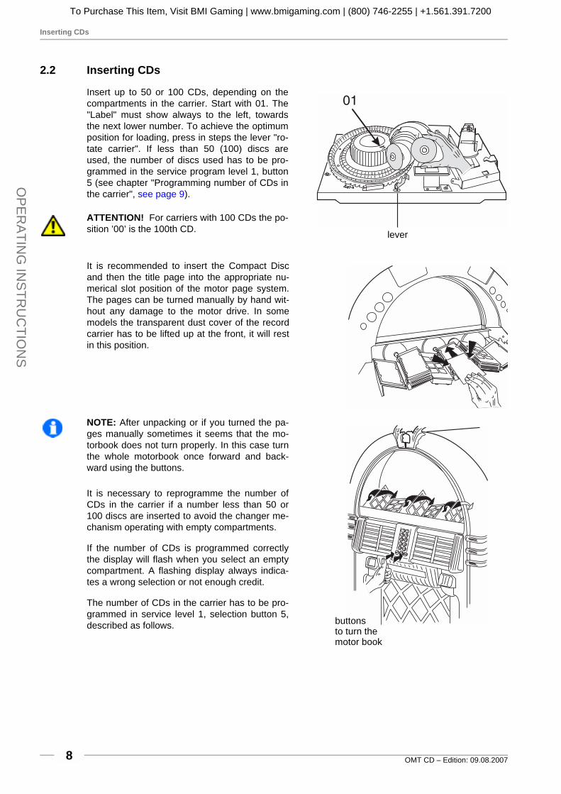
3.5 Free play
To set the jukebox to free play:
1. In case there are already jumpers in the rows GPand BS, notice their position (for later resetting tocoin operation) and remove them.
2. Set a jumper from 0 to F (free play) in the row GP on the SCC unit.
3. Press ‘LT’ button.
4. Now one track is selectable without coin insertion.
5. In between two to six plays are selectable by setting an additional jumper in the row ‘BS’ (BonusStep) from 0 to 2 or from 0 to 6.
6. Up to 47 tracks are pre-selectable by setting a jumper in the row ‘BS' from 0 to 7.
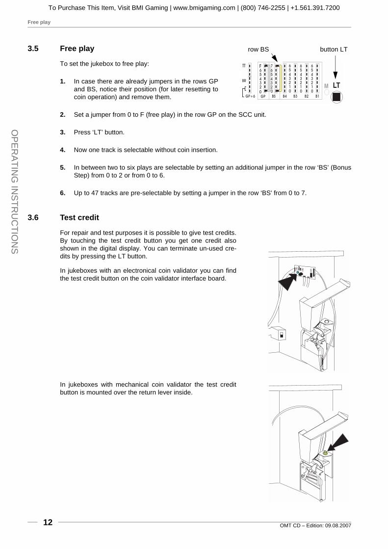
3.6 Test credit
For repair and test purposes it is possible to give test credits.By touching the test credit button you get one credit alsoshown in the digital display. You can terminate un-used cre-dits by pressing the LT button.
In jukeboxes with an electronical coin validator you can findthe test credit button on the coin validator interface board.
In jukeboxes with mechanical coin validator the test creditbutton is mounted over the return lever inside.
M LT
GP BS B4 B3 B2 B1GP+6
BR
0 0
2
3
4
5
6
2
3
4
5
6
F
2
3
4
5
6
1
0
2
3
4
5
6
1
0
2
3
4
5
6
1
0
7TT
row BS button LT
To Purchase This Item, Visit BMI Gaming | www.bmigaming.com | (800) 746-2255 | +1.561.391.7200

Test credit
OMT CD – Edition: 09.08.2007 13
OP
ER
ATI
NG
INS
TRU
CTI
ON
S
pu
lse
pla
ys
fro
mG
P:
fro
mb
on
us
ste
p
pla
ys
B1
...B
4
tota
lp
lays
inse
rte
dm
on
ey
1.
2.
3.
4.
5.
6.
7.
8.
9.
10
.11
.1
2.
13
.1
4.
15
.1
6.
17
.1
8.
19
.2
0.
21
.2
2.
23
.2
4.
25
.
Pri
ce
se
ttin
gs:
1 2 4 5 T1
10
20 T
+B
....
....
....
...
....
....
....
...
....
....
....
...
....
....
....
...
....
....
....
...
....
....
....
...
....
....
....
...
....
....
....
...
....
....
....
...
testcre
dit
GN
D
+3
5V
!
To Purchase This Item, Visit BMI Gaming | www.bmigaming.com | (800) 746-2255 | +1.561.391.7200

How to select a track
OMT CD – Edition: 09.08.200714
OP
ER
ATIN
G IN
STR
UC
TION
S
4 Track selection
4.1 How to select a track
If credit exists or free play is set you can select tracks by means of the buttons 0 - 9 on the keyboard.First enter the number of the CD with two digits, then the track with two digits too. Example: CD 2,track 9: Enter 0 - 2 - 0 - 9 (Exception: CD 100 = 00.)
4.2 The button R
You can delete wrongly entered numbers up to thethird digit by means of the button R (Reset). But afterhaving entered the fourth digit the jukebox stores andexecutes a selection. By pressing the button R theavailable credit will be displayed for a few seconds.
4.3 The display flashes
After entering the fourth digit of a selection the jukebox starts to searchand play the selected CD immediately. If the display flashes the enteredselection was not valid. Check:
! if credit is available or
! if the selection is higher then the programmed number of CDs in the carrier
If you select a higher track number than available on a CD the jukebox overcounts the tracks andstarts at the beginning.
Example: CD 03 contains 17 tracks. But selected track is 0 - 3 - 1 - 9. The jukebox plays track 02 ofCD 03.
A maximum of 25 tracks per CD can be selected!
button R
To Purchase This Item, Visit BMI Gaming | www.bmigaming.com | (800) 746-2255 | +1.561.391.7200

I do not like this track - the button CANCEL
OMT CD – Edition: 09.08.2007 15
OP
ER
ATI
NG
INS
TRU
CTI
ON
S
4.4 I do not like this track - the button CANCEL
If you do not like a track you can cancel it by pressingthe button 'CANCEL' at the rear side of the jukebox or atthe remote control. The jukebox stops playing or playsthe next track if a selection has already been made.
You can terminate all selections only by pressing the but-ton LT on the SCC unit .
CANCELMUTE
MIN MAX
MIN MAX
CANCELMUTE
0058407
MIN MAX
ICNTERN
HANNEL 1
MIN MAX
EC
XTERN
HANNEL 2
VOLUME
BASS
TREBLE
BALANCE- +
MODE PRESET
CANCEL MUTE
buttonCANCEL
controlterminal F91
controlterminal K99
To Purchase This Item, Visit BMI Gaming | www.bmigaming.com | (800) 746-2255 | +1.561.391.7200
Volume, sound and balance control - amplifier K99
OMT CD – Edition: 09.08.200716
OP
ER
ATIN
G IN
STR
UC
TION
S
5 Volume, sound and balance control
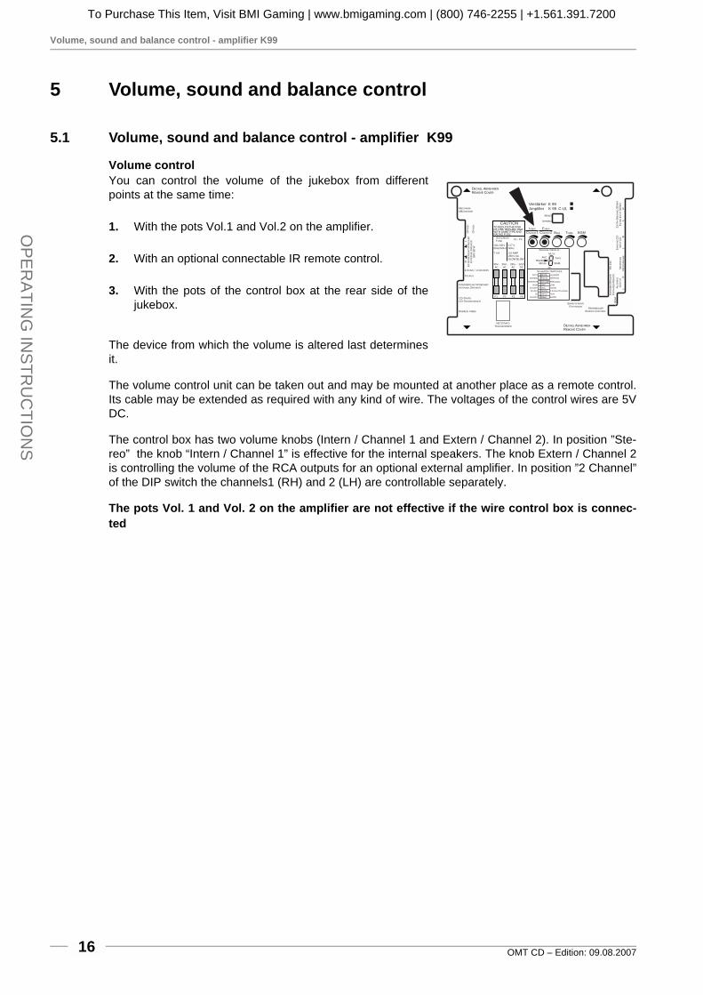
5.1 Volume, sound and balance control - amplifier K99
Volume controlYou can control the volume of the jukebox from differentpoints at the same time:
1. With the pots Vol.1 and Vol.2 on the amplifier.
2. With an optional connectable IR remote control.
3. With the pots of the control box at the rear side of thejukebox.
The device from which the volume is altered last determinesit.
The volume control unit can be taken out and may be mounted at another place as a remote control.Its cable may be extended as required with any kind of wire. The voltages of the control wires are 5VDC.
The control box has two volume knobs (Intern / Channel 1 and Extern / Channel 2). In position ”Ste-reo” the knob “Intern / Channel 1” is effective for the internal speakers. The knob Extern / Channel 2is controlling the volume of the RCA outputs for an optional external amplifier. In position ”2 Channel”of the DIP switch the channels1 (RH) and 2 (LH) are controllable separately.
The pots Vol. 1 and Vol. 2 on the amplifier are not effective if the wire control box is connec-ted
CAUTIONTO REDUCETHE RISKOF FIRE REPLACE ONLYWITH SAMETYPE ANDRATING FUSE
Bass Treble BGM
M
S
ONO
TEREO
ANAL HANNEL
TEREO
2-K / 2-C
S
SF
ICHERUNG
USEF1 - F4
100-240V50Hz/60Hz
117 V60Hz
3,0 AMP250 V ACSLOW BLOW
T 4 A
30V~AC
F1
26V~AC
F2
26V~AC
F3
12V=DC
F4
I LNTERNER AUTSPRECHER
NTERNAL PEAKERI S
OP
TIO
N
OP
TIO
N
RL
EL
ES
8/80
W
XT
ER
NE
RA
UT
SP
RE
CH
ER
XT
ER
NA
LP
EA
KE
R
W
CD-TCD-T
RAFO
RANSFORMER
B -TUBBLE UBES
NT
ETZTRAFO
RANSFORMER
EERWEITERUNG
XTENSIONF
R CERNREGLER
EMOTE- ONTROL
RS
232
BG
M
IR
IR
NF
RA
RO
T-E
GLE
R
NF
RA
RE
D-
EM
OT
E
A OL
R
US
GA
NG
UT
PU
T
EC
DI
CD
LR
ING
AN
G
NP
UT
EE
300m
VX
TR
A
XT
RAE
300m
VI
LR
ING
AN
G
NP
UT
MM
IKR
OF
ON
ICR
OP
HO
NE
MECHANIK
MECHANISM
D AR C
ECKEL BNEHMEN
EMOVE OVER
D AR C
ECKEL BNEHMEN
EMOVE OVER
IC 1
ntern
hannel
EC 2
xtern
hannel
Verstärker K 99Amplifier K 99 C-UL
AVCRS232
MICRO
TAPE
MUTE
A / DNZEIGE ISPLAY
BGM
ok.
S / SCHALTER WITCHES
A /OUS FF
A /OUS FF
E /OIN N
E /OIN N
A
A
VC
VC
MODESTEREO 2-K /2CANAL HANNEL
INPUTCD TAPE
BGM
1
1
3
5
2
2
4
6
SEPARATE
NORMAL
AUTO
VOLUME
RS232
MUTE
HIGH LOW
PARALLEL
SERVICE
AUS/OFF
To Purchase This Item, Visit BMI Gaming | www.bmigaming.com | (800) 746-2255 | +1.561.391.7200
Volume, sound and balance control - amplifier K99
OMT CD – Edition: 09.08.2007 17
OP
ER
ATI
NG
INS
TRU
CTI
ON
S
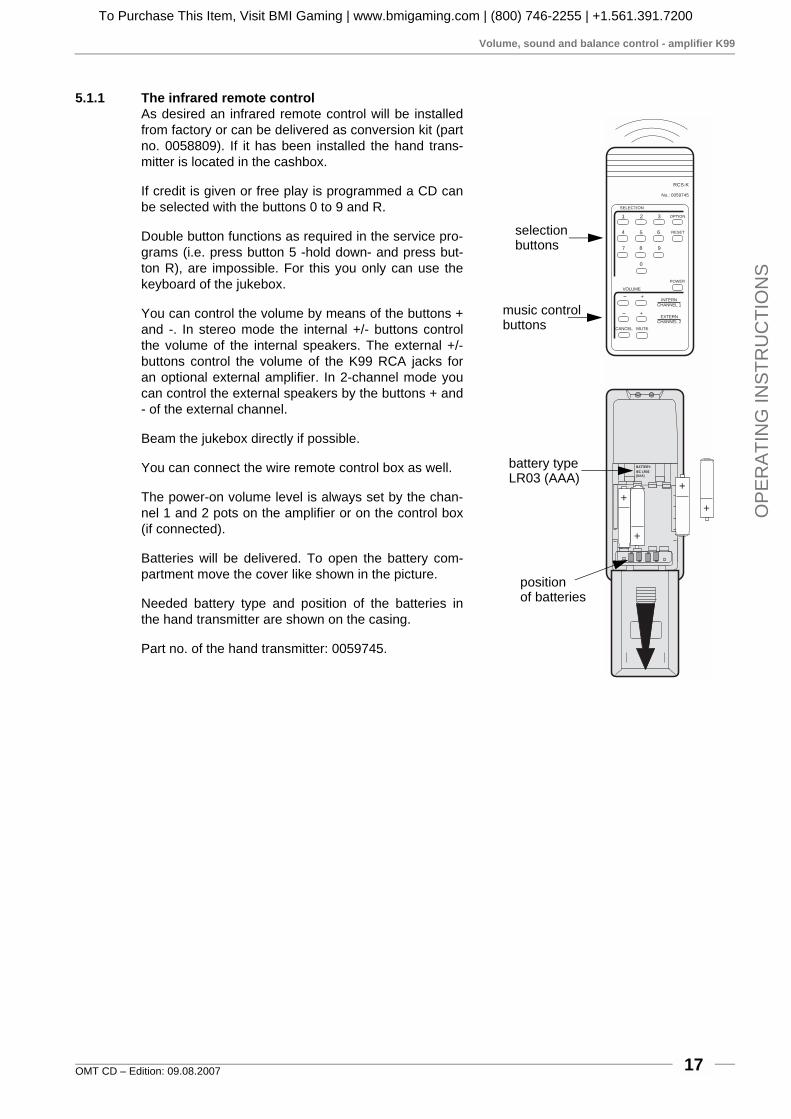
5.1.1 The infrared remote controlAs desired an infrared remote control will be installedfrom factory or can be delivered as conversion kit (partno. 0058809). If it has been installed the hand trans-mitter is located in the cashbox.
If credit is given or free play is programmed a CD canbe selected with the buttons 0 to 9 and R.
Double button functions as required in the service pro-grams (i.e. press button 5 -hold down- and press but-ton R), are impossible. For this you only can use thekeyboard of the jukebox.
You can control the volume by means of the buttons +and -. In stereo mode the internal +/- buttons controlthe volume of the internal speakers. The external +/-buttons control the volume of the K99 RCA jacks foran optional external amplifier. In 2-channel mode youcan control the external speakers by the buttons + and- of the external channel.
Beam the jukebox directly if possible.
You can connect the wire remote control box as well.
The power-on volume level is always set by the chan-nel 1 and 2 pots on the amplifier or on the control box(if connected).
Batteries will be delivered. To open the battery com-partment move the cover like shown in the picture.
Needed battery type and position of the batteries inthe hand transmitter are shown on the casing.
Part no. of the hand transmitter: 0059745.
RCS-K
No.: 0059745
SELECTION
1 2 3
4 5 6 RESET
POWER
OPTION
7 8 9
0
- +
- +
BATTERY:
IEC LR03(AAA)
+
+
+
+
CANCEL MUTE
VOLUME
INTERNCHANNEL 1
EXTERNCHANNEL 2
selection
music control
battery typeLR03 (AAA)
positionof batteries
buttons
buttons
To Purchase This Item, Visit BMI Gaming | www.bmigaming.com | (800) 746-2255 | +1.561.391.7200

Volume, sound and balance control - amplifier F91
OMT CD – Edition: 09.08.200718
OP
ER
ATIN
G IN
STR
UC
TION
S
5.2 Volume, sound and balance control - amplifier F91
The control terminal at the rearWith the control terminal at the rear side of the jukeboxthe volume, treble, bass and balance can be controlledindividually.
After power up or if no button has been pressed for ap-prox. 5 sec or after the button PRESET has beenpressed, the terminal stays in the mode "VOLUME".The LED "VOLUME" lights. In this mode you can cont-rol the volume by means of the buttons '+' and '-'.
One LED corresponds to each mode. All modes areaccessible by pressing the ‘mode’ button. With the but-tons '+' and '-' treble, bass or balance can be cont-rolled.
The control terminal can be taken out and be used asa wired remote control.
ATTENTION! Depending on adjusted volume of thejukebox noise levels of more than 70 dB can be rea-ched.
The meanings of the buttons...
! MODE: Switches to the next operating mode. Afterabout 5 seconds without operating any buttons, ‘vo-lume’ mode is resumed.
! PRESET: Volume, bass, treble, and balance areset to the pre-set according to DIP switch setting.Actual mode is set to ‘Volume’.
! CANCEL: Rejects a playing track. If album play isselected the next track will be played.
! MUTE: As long as this button is activated, the amp-lifier output is muted.
MODE PRESET
CANCEL MUTE
0039661
VOLUME
BASS
TREBLE
BALANCE
- +
+/-
+/-
+/-
+/-
VOLUME
BASS
TREBLE
BALANCE
Press button MODE
Press button MODE
Press button MODE
Press button MODE
LED Volumelights
LED Basslights
LED Treblelights
LED Balancelights
currentmode
To Purchase This Item, Visit BMI Gaming | www.bmigaming.com | (800) 746-2255 | +1.561.391.7200

Volume, sound and balance control - amplifier F91
OMT CD – Edition: 09.08.2007 19
OP
ER
ATI
NG
INS
TRU
CTI
ON
S
5.2.1 The infrared remote controlAs desired an infrared remote control will be installedfrom factory or can be delivered as conversion kit (partno. 0040435). If it has been installed the hand trans-mitter is located in the cashbox.
If credit is given or free play is programmed a CD canbe selected with the buttons 0 to 9 and R.
Double button functions as required in the service pro-grams (i.e. press button 5 -hold down- and press but-ton R), are impossible. For this you can use thekeyboard of the jukebox only.
The meanings of the music control buttons are accor-ding to the buttons on the control terminal on the rearside of the jukebox (ref. to the prev. chapter).
The receiver eye of the infrared remote control is loca-ted behind the hole between the design elements ontop of the front door. Beam this point directly if pos-sible.
The common control terminal can be connected besi-des. It can be mounted outside to display the actualmode.
Batteries will be delivered. To open the battery com-partment move the cover as shown in the picture.
The required battery type and position of the batteriesin the hand transmitter are shown on the casing.
Part no. of the hand transmitter: 0040443.
RCSART.NR.: 0040443
SELECTION
1 2 3
4 5 6 RESET
7 8 9
0
+/-
+/-
+/-
+/-
VOLUME
BASS
TREBLE
BALANCE
MODE
MODE
MODE
MODE
MUSIC
MODE PRESET
CANCEL MUTE
- +
BATTERY:
IEC LR03
(AAA)
+
+
+
+
selection
music control
battery typeLR03 (AAA)
positionof batteries
buttons
buttons
To Purchase This Item, Visit BMI Gaming | www.bmigaming.com | (800) 746-2255 | +1.561.391.7200

Pre-settings for volume
OMT CD – Edition: 09.08.200720
OP
ER
ATIN
G IN
STR
UC
TION
S
5.3 Pre-settings for volume
After power on of the jukebox or after pressing the but-ton ‘preset’ the values of volume, bass and treble re-ach the values set by the DIP switches.You can set the basic values for volume in 63 stepsfrom zero up to maximum volume.At the amplifier front side, opening “Volume”, thereare 6 DIP-switches for each channel. These switcheshave different values (1, 2 ... to 32). If you add all thevalues of the switches in position “ON” you will get thevalue for the set volume.Consequently the switches 32 and 16 give a coarseadjustment whilst the lower numbers may be used forfine adjustment.You can find the recommended settings on the ampli-fier cover.
NOTE: If all switches are in position OFF no volume, ifall switches are in position ON, the maximum volumeappears at power on !
5.3.1 Pre-settings for bass and trebleSimilarly the values for bass and treble can be set. Bothchannels should be adjusted the same.
Three DIP-switches with the values 1, 2, 4 are provided foreach bass and treble. You can choose 7 different steps fromminimum to maximum. Adding all switches set to "ON" getsthe set value.
The recommended factory settings are printed on the ampli-fier cover.
If you change the DIP-switch settings while the jukeboxoperates remember that the new settings will only takeeffect after having pressed the button ‘PRESET’ at thecontrol terminal.
Verstärker-Sicherungen
210V - 240V
Si 1/Si 301Si 2/Si 302
Si 102/Si 103Si 100/Si 101
MT 4A T 3,15A
100V - 117V
Si 1/Si 301Si 2/Si 302
T 5A
Si 102/Si 103Si 100/Si 101
T 3A
Zur Beachtung Nur Sicherungen mit gleicher Größe undgleichem Wert verwenden um Schäden zu vermeiden.
Caution: To reduce the risk of fire replace only withsame type and rating fuses.
Achtung!Vor Abnahme der Kappe den Netzsteckerziehen!Attention!Pull power plug before opening protectivelid!
Leuchtstofflampen/Flourescent Lamps
230V / 117V
/ Amplifier FusesNetzspannung
50/60 Hz
Mains Voltage50/60 cps
240230
210
100
220
117
Low Level
BGM
Mic.-Kit
L
R
Line Out
L
R
Input Tape
L
R
Input CD
Amplifier F910039155
BGM Level
R
L
L R
ClippingP10Remote
P10Remote
P4
1
24
12
4
Tone
off on
Treble
Bass
1
24
8
16
32
1
2
4
8
1632
Volume
off on
R
L
Mode
Input
CD
Stereo
Tape
2-Kanal
R
L
1
24
8
16
32
1
2
4
8
1632
1
24
12
4
DIP switchrecommended
settings
To Purchase This Item, Visit BMI Gaming | www.bmigaming.com | (800) 746-2255 | +1.561.391.7200
Pre-settings for volume
OMT CD – Edition: 09.08.2007 21
OP
ER
ATI
NG
INS
TRU
CTI
ON
S
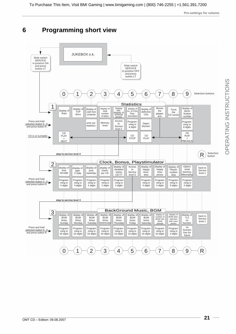
6 Programming short view
0 1 2 3 4 5 8 9 R
Statistics
Clock, Bonus, PlaystimulatorClock, Bonus, Playstimulator
BackGround Music, BGMBackGround Music, BGM
JUKEBOX o.k.
0 1 2 3 4 5 6 7 8 9
R
3
1
Slide switchSERVICE
in position ONand pressbutton LT
Slide switchSERVICE
in position OFFand pressbutton LT
2
6 7
Selection buttons
Selectionbutton
display offlops
display ofTOPdiscs
CDPLAY
+NEXT
display ofcash boxcontents
print outstatistics
display oftotal
numberof plays
Memoryreset
Displaytest,
EPROMversion
display of
Accessto
Servicelevel 2
display ofno. of CDs,
Play-stimulator
Program-ming in4 digits
CDSTOP
CDPLAY
Datenlöschen
display ofdefective
CDs
Movesthe
gripperarm
Turnsthe
CD carrier
display ofidenti-ficationnumber
Program-ming in8 digits
CDPLAY
+PREVIOUS
Press and holdselection button 0...9and press button R
Press and holdselection button 0...9and press button R
Press and holdselection button 0...9and press button R
CD is on turntable
step to service level 2
step to service level 3
display oftime
HH:MM
Program-ming in4 digits
Program-ming in16 digits
Program-ming in16 digits
Program-ming in16 digits
Program-ming in16 digits
Program-ming in16 digits
Program-ming in16 digits
Program-ming in16 digits
Program-ming in16 digits
Program-ming in4 digits
Program-ming in4 digits
Program-ming in4 digits
Program-ming in2 digits
Program-ming in4 digits
Program-ming in4 digits
Program-ming in4 digits
Program-ming in8 digits
Program-ming in2 digits
display ofdate
TT:MM
display ofyear,
weekday
display oftracksper CD
display ofdisabledtracksCD:TT
Accessto
Servicelevel 3
display ofHappyHour-time
display ofHappyHourprices
display ofPlaysti-mulator
time
Option:reset
memory,Albumplay
back toServicelevel 1
back toServicelevel 1
display ofBGMtimes
Sunday
display ofBGMtimes
Monday
display ofBGMtimes
Tuesday
display ofBGMtimes
Wednesday
display ofBGMtimes
Thursday
display ofBGMtimesFriday
display ofBGMtimes
Saturday
display ofnumber ofBGM CDs
BGMperiods
display ofBGM start,selectionwith coins
yes/no
display of712no
function
nofunctionfree forfuture
To Purchase This Item, Visit BMI Gaming | www.bmigaming.com | (800) 746-2255 | +1.561.391.7200

Call up service programs
OMT CD – Edition: 09.08.200722
OP
ER
ATIN
G IN
STR
UC
TION
S
7 Jukebox programmingAdditional features like Playstimulator, BGM time and Happy Hour time are programmable. Thesefeatures are programmable in the service mode of the SCC unit.
7.1 Call up service programs
NOTE: To keep the data stored when po-wer is off the plug “Memory” must be setto “ON” position on the SCC unit, other-wise all programmed data in service le-vels are reset when power is interrupted.
Call up service programs:
1. Set slide switch “Service” from posi-tion OFF to ON, then press the LTbutton. Service level 1 is reached,display shows ’0 0’.
2. Press button 4 - hold it - and pressbutton R, display is dark, service le-vel 2 is reached.
3. Press button 5, display is dark, ser-vice level 3 is reached.
NOTE: If button R is pressed first in ser-vice levels 2 or 3, the S&CC will jumpback to service level 1 automatically.
7.2 How to leave service programs
1. Set the slide switch SERVICE in po-sition off.
2. Press button LT.
" The changer starts an initialisationrun. After this the jukebox is ready to operate.
1. Service inposition ON
2. Press button LT
Press button 4 - hold it -and press button R
Press button 5
Button R
Button R
Service level 1
Display:
Service level 2
Display:
Service level 3
Display:
Statistics
Clock, Bonus,
Playstimulator
BackGround
Music (BGM)
Memoryin positionON
0040264
1
2
4
5
T1
10
20T
+B
M LT
MemoryON
OFF
P6
P5
P8Selection &
Credit ComputerCDM 4I / CDM 12
K
ON
OFF
Service
GP BS B4 B3 B2 B1GP+6
BR
0 0
2
3
4
5
6
2
3
4
5
6
F
2
3
4
5
6
1
0
2
3
4
5
6
1
0
2
3
4
5
6
1
0
7TT
To Purchase This Item, Visit BMI Gaming | www.bmigaming.com | (800) 746-2255 | +1.561.391.7200

Programming of time functions
OMT CD – Edition: 09.08.2007 23
OP
ER
ATI
NG
INS
TRU
CTI
ON
S
7.3 Programming of time functions
Service level 2It is necessary to program the time, date and weekdayonce or at least to control these settings. Only then thejukebox can switch on and off the playstimulator or theBack Ground Music at the desired time. It is useful toprogram time, date and weekday in a single pass.
To program the time (and also the date):
1. Set the slide switch ‘service’ at the SCC-unit to ON.
2. Press ‘LT’ button.
3. Press selection button 4 -hold down- and press selection button R than release both buttons.
4. Service level 2 is reached.
7.3.1 Clock setting, level 2 button 0
5. Press selection button 0. The display shows the current time.If the displayed time is not correct:
6. Press selection button 0 -hold down- and press selection but-ton R. Release both buttons.
7. Enter the correct time with four digits.
7.3.2 Set date, level 2 button 1
8. Press selection button 1. The display shows the current date.If the displayed date is not correct:
9. Press selection button 1 -hold down- and press selection but-ton R. Release both buttons.
10. Enter the correct date with four digits.
7.3.3 Set year and weekday, level 2 button 2
11. To display the year and the weekday press selection button 2:The weekdays are assigned to numbers as shown.
12. To program press selection button 2 -hold down- and press selection button R. Release bothbuttons.
13. Enter the correct year with two digits, then enter a 0 followed by the number of the weekday.
0 = Sunday 4 = Thursday1 = Monday 5 = Friday2 = Tuesday 6 = Saturday3 = Wednesday
LT button
MEMORY - Stecker von OFFauf ON umstecken, wennTop tunes, Popularitätszähleroder Kassenzähler arbeiten soll.
Move MEMORY Plug from OFFto ON if Top tunes, Pop Meter orCash Box Content Registrationis required.
Placer la prise MEMORY enposition ON, de la position OFFsi le Top Tunes, le compteur depopularité et la contenu de lacaisse sont demandés.
ACHTUNG:
ATTENTION:
ATTENTION:
Selection &Credit Computer
CDM 12 ON
OFFMemory
0040264
P8
P5
P6 16
15
18
GPGP + 6 BS B4 B3 B2 B1
F654320
7654320
6543210
6543210
6543210
ONOFF
SERVICE
Z
K
T.T.+2+3BR
1245
T11020
+B
T
M LT
slide switchservice
minuteshours
Example:
monthday
Example:
yearweekday
Example:
To Purchase This Item, Visit BMI Gaming | www.bmigaming.com | (800) 746-2255 | +1.561.391.7200

Automatic random select (Playstimulator)
OMT CD – Edition: 09.08.200724
OP
ER
ATIN
G IN
STR
UC
TION
S
Exit the service program:
1. Set the slide switch ‘service’ at the SCC unit to OFF.
2. Press ‘LT’ button.
" The changer starts an initialisation run. After this the jukebox is ready to use.
7.4 Automatic random select (Playstimulator)
If the Playstimulator is programmed the jukebox plays random tracks of the CDs in carrier registeredin the service program level 1, button 5. CDs declared as BGM CDs (ref. to the next chapter) will notbe used! The time between the last track played by inserted money and the first random track of thePlaystimulator is programmable from 1 up to 98 min. This time is also the repeat time between tworandom plays. The volume is the same as in normal operation. The Playstimulator will be interruptedimmediately when a selection is made and restarts after having played the selected track(s).
By means of an optional switch you can also switchthe box to CONTINUOUS PLAY MODE without anyneed to enter the service program. Part number ofthis switch is 0034410. It has to be connected to P8 ofthe SCC unit. (This switch is standard for all One MoreTime CD).
The Playstimulator only works:
! if Back Ground Music is not activated at thesame time
! if time is programmed correctly! iif no credit left
Repeat time programmingTo programme the repeat time for the Playstimulator (service program level 1):
1. Set the slide switch ‘service’ at the SCC-unit to ON.
2. Press ‘LT’ button.
3. Make sure that all time details are programmed properly otherwise you have to reprogramme(see chapter 'The internal clock')
4. Press selection button 5. Display shows four digits.
5. Both LH digits show the number of CDs in the carrier, this number has to be indentical with thereal number. Both RH digits show whether Playstimulator is enabled (01-99) or disabled (00).The numbers 01 up to 98 show repeat time between two random tracks in minutes, 99 meanscontinuous play without any break.
Continuous
Play
on
off
0040264
1
2
4
5
T1
10
20T
+B
M LT
MemoryON
OFF
P6
P5
P8Selection &
Credit ComputerCDM 4I / CDM 12
K
ON
OFFService
GP BS B4 B3 B2 B1GP+6
BR
0 0
2
3
4
5
6
2
3
4
5
6
F
2
3
4
5
6
1
0
2
3
4
5
6
1
0
2
3
4
5
6
1
0
7TT
CONTINUOUSPLAY switch
To Purchase This Item, Visit BMI Gaming | www.bmigaming.com | (800) 746-2255 | +1.561.391.7200

Automatic random select (Playstimulator)
OMT CD – Edition: 09.08.2007 25
OP
ER
ATI
NG
INS
TRU
CTI
ON
S
A = number of CDs in the carrier (00 = 100)
B = repeat time programmed to 10 minutes
A = 50 CDs in carrier
B = no random plays
A = 63 CDs in carrier
B = Playstimulator on, continuousplay
6. Note the number of CDs in carrier.
7. Press selection button 5 -hold it- and press selection button R.Display goes dark. Enter the noted number of CDs in carrier and Playstimulator interval time (or'00' for Playstimulator OFF or '99' for continuous play) with four digits.
7.4.1 Programming start and stop timeIf start and stop time is programmed the jukebox only plays random tracks in this time period.
You can not programme the Playstimulator over 24.00 o’clock (e.g. 23.00 to 2.00 o'clock) !
Call up service program 2 by pressing the slide switch on SCC unit to position ON, press button LT,then press button 4 -hold it- and press selection button R. Then
press selection button 8. The display shows at first a flashing ’1’. This means ’start time’.
Then the time will be displayed, here 14.05 o’clock (2.05 p.m.).
Press selection button 8 once again. Now the display shows a flashing ’2’.This means ’stop time’.
Then the time will be displayed, here 18.30 o’clock (6.30 p.m.).
To reprogramme press selection button 8 - hold - and press selection button R. Release both but-tons. The digital display goes dark. Enter the start and stop time with eight digits.
Example:
A B
Example:
A B
Example:
A B
To Purchase This Item, Visit BMI Gaming | www.bmigaming.com | (800) 746-2255 | +1.561.391.7200

Back Ground Music (BGM)
OMT CD – Edition: 09.08.200726
OP
ER
ATIN
G IN
STR
UC
TION
S
Example: The jukebox should play random tracks from 09.00 in the morning to17.00 in the af-ternoon..
To check the start time: press selection button 8. To check the stop time: press selection button 8again.
If the Playstimulator does not work. Check if:
! the clock is set correctly ?
! start and stop time is programmed?
! repeat time is set correctly (not 0)?
! BGM play mode is disabled (ref. to next chapter).
! credits are still in memory. Display the remaining credits by pressing button R. If so, delete withbutton LT.
Exit the service program:
1. Set the slide switch ‘service’ at the SCC unit to OFF.
2. Press ‘LT’ button.
" The changer starts an initialisation run. After this the jukebox is ready to operate.
7.5 Back Ground Music (BGM)
If BGM is programmed and activated a random track from the CDs declared for BGM will be played.The time between the last selected played track and the first BGM track is programmable between 1and 98 minutes. This time is also the repeat time between two BGM tracks.
For the K99 amplifier the reproduction loudness will bereduced by a certain factor in the BGM (Back GroundMusic) mode.You also can switch “BGM” on by means of the DIPswitch “BGM” for test purposes. The RH bottom seg-ment of the status display on the amplifier indicates“BGM active”. You can adjust the volume attenuationwith the pot “BGM”, as long it is active.
Enter: 0 - 9 - 0 - 0 - 1 - 7 - 0 - 0start time stop time
Bass Treble BGM
EERWEITERUNG
XTENSIONF
R CERNREGLER
EMOTE- ONTROL
RS
232
IR
IR
NF
RA
RO
T-E
GLE
RN
FR
AR
ED
-E
MO
TE
IC 1
ntern
hannel
EC
xtern
hannel 2
AVCRS232
MICRO
TAPE
MUTE
A / DNZEIGE ISPLAY
BGM
ok.
S / SCHALTER WITCHES
A /OUS FF
A /OUS FF
E /OIN N
E /OIN N
A
A
VC
VC
MODESTEREO 2-K /2CANAL HANNEL
INPUTCD TAPE
BGM
1
1
3
5
2
2
4
6
SEPARATE
NORMAL
AUTO
VOLUME
RS232
MUTE
HIGH LOW
PARALLEL
SERVICE
AUS/OFF
amplifier K99
To Purchase This Item, Visit BMI Gaming | www.bmigaming.com | (800) 746-2255 | +1.561.391.7200

Back Ground Music (BGM)
OMT CD – Edition: 09.08.2007 27
OP
ER
ATI
NG
INS
TRU
CTI
ON
S
F91: The volume for BGM reproduction is redu-ced compared to the normal volume. It is adjus-table with the two BGM pots (RH channel / LHchannel) on the amplifier. BGM mode is activewhen the LED on the amplifiers lights. Thesource of the BGM control signal is the SCCunit plug brown (X6), pin 1. Once the BGMmode is activated, it is not possible to operatethe Playstimulator.
If a selection is made by means of coin insertionthe track being played will be interrupted imme-diately. Two intervals can be programmed foreach weekday.
To enable BGM (service program, level 3) :
1. Set the slide switch ‘service’ at the SCC-unit to ON.
2. Press ‘LT’ button.
3. Press selection button 4 -hold down- and press selection button R then release both buttons.
4. Press selection button 5. Service level 3 is reached. The display is dark. At this level all BGMoptions can be checked and/or programmed.
For the K99 amplifier the reproduction loudness will be reduced by a certain factor in the BGM (BackGround Music) mode.
You also can switch “BGM” on by means of the DIP switch “BGM” for test purposes. The RH bottomsegment of the status display on the amplifier indicates “BGM active”. You can adjust the volume at-tenuation with the pot “BGM”, as long it is active.
7.5.1 Number of BGM CDs and repeat timePress selection button 7, the display shows e.g.:
A = number of BGM CDs; disabled for PlaystimulatorBGM OFF = 00.
B = Repeat time between the single BGM tracks (10 min.)BGM-continuous play = 00
To programme press selection button 7 -hold down- andpress selection button R. Release both buttons. The displaygoes dark. Enter the number of CDs and the repeat time with4 digits.
Low Level
BGM
Mic.-Kit
L
R
Line Out
L
R
Input Tape
L
R
Input CD
Amplifier F910039155
BGM Level
R
L
L R
ClippingP10Remote
P10Remote
P4
1
2
412
4
Tone
off on
Treble
Bass
1
24
8
16
32
1
2
4
8
16
32
Volume
off on
R
L
Mode
Input
CDStereo
Tape2-Kanal
R
L
BGM light emittingdiode (yellow), indicates whetherBGM is active
BGM trim pots
amplifier F91
Example:
A B
5 CDs reserved for BGM,repeat time 10 min.
To Purchase This Item, Visit BMI Gaming | www.bmigaming.com | (800) 746-2255 | +1.561.391.7200
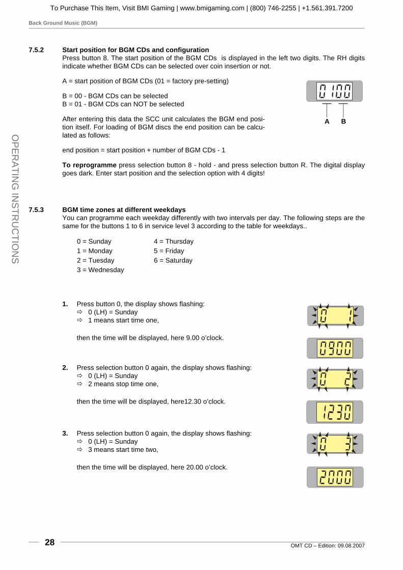
Back Ground Music (BGM)
OMT CD – Edition: 09.08.200728
OP
ER
ATIN
G IN
STR
UC
TION
S
7.5.2 Start position for BGM CDs and configurationPress button 8. The start position of the BGM CDs is displayed in the left two digits. The RH digitsindicate whether BGM CDs can be selected over coin insertion or not.
A = start position of BGM CDs (01 = factory pre-setting)
B = 00 - BGM CDs can be selectedB = 01 - BGM CDs can NOT be selected
After entering this data the SCC unit calculates the BGM end posi-tion itself. For loading of BGM discs the end position can be calcu-lated as follows:
end position = start position + number of BGM CDs - 1
To reprogramme press selection button 8 - hold - and press selection button R. The digital displaygoes dark. Enter start position and the selection option with 4 digits!
7.5.3 BGM time zones at different weekdaysYou can programme each weekday differently with two intervals per day. The following steps are thesame for the buttons 1 to 6 in service level 3 according to the table for weekdays..
1. Press button 0, the display shows flashing:# 0 (LH) = Sunday# 1 means start time one,
then the time will be displayed, here 9.00 o’clock.
2. Press selection button 0 again, the display shows flashing:# 0 (LH) = Sunday# 2 means stop time one,
then the time will be displayed, here12.30 o’clock.
3. Press selection button 0 again, the display shows flashing:# 0 (LH) = Sunday# 3 means start time two,
then the time will be displayed, here 20.00 o’clock.
0 = Sunday 4 = Thursday1 = Monday 5 = Friday2 = Tuesday 6 = Saturday3 = Wednesday
A B
To Purchase This Item, Visit BMI Gaming | www.bmigaming.com | (800) 746-2255 | +1.561.391.7200
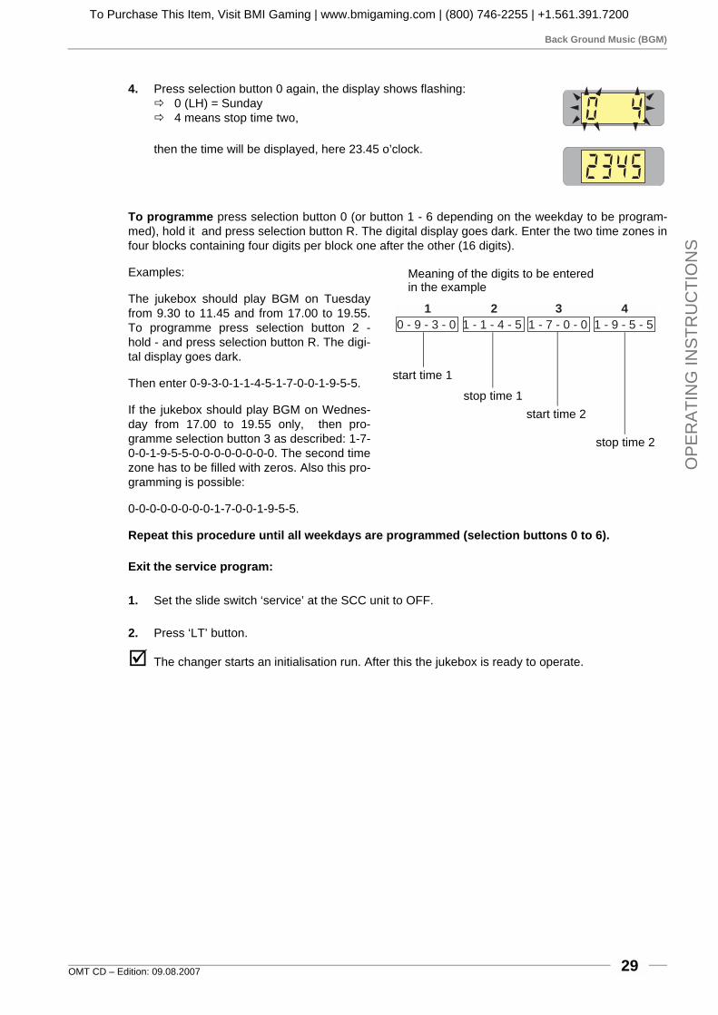
Back Ground Music (BGM)
OMT CD – Edition: 09.08.2007 29
OP
ER
ATI
NG
INS
TRU
CTI
ON
S
4. Press selection button 0 again, the display shows flashing:# 0 (LH) = Sunday# 4 means stop time two,
then the time will be displayed, here 23.45 o’clock.
To programme press selection button 0 (or button 1 - 6 depending on the weekday to be program-med), hold it and press selection button R. The digital display goes dark. Enter the two time zones infour blocks containing four digits per block one after the other (16 digits).
Examples:
The jukebox should play BGM on Tuesdayfrom 9.30 to 11.45 and from 17.00 to 19.55.To programme press selection button 2 -hold - and press selection button R. The digi-tal display goes dark.
Then enter 0-9-3-0-1-1-4-5-1-7-0-0-1-9-5-5.
If the jukebox should play BGM on Wednes-day from 17.00 to 19.55 only, then pro-gramme selection button 3 as described: 1-7-0-0-1-9-5-5-0-0-0-0-0-0-0-0. The second timezone has to be filled with zeros. Also this pro-gramming is possible:
0-0-0-0-0-0-0-0-1-7-0-0-1-9-5-5.
Repeat this procedure until all weekdays are programmed (selection buttons 0 to 6).
Exit the service program:
1. Set the slide switch ‘service’ at the SCC unit to OFF.
2. Press ‘LT’ button.
" The changer starts an initialisation run. After this the jukebox is ready to operate.
0 - 9 - 3 - 0 1 - 1 - 4 - 5 1 - 7 - 0 - 0 1 - 9 - 5 - 5
1 2 3 4
Meaning of the digits to be enteredin the example
start time 1
start time 2stop time 1
stop time 2
To Purchase This Item, Visit BMI Gaming | www.bmigaming.com | (800) 746-2255 | +1.561.391.7200

HappyHour pricing (additional bonus plays)
OMT CD – Edition: 09.08.200730
OP
ER
ATIN
G IN
STR
UC
TION
S
7.6 HappyHour pricing (additional bonus plays)
During the HappyHour time additional bonus plays can be given. HappyHour time zone and numberof additional bonus plays have to be programmed as follows.
7.6.1 Programming of the HappyHour start and stop time, level 2 button 6
1. Set the slide switch ‘service’ at the SCC unit to ON.
2. Press ‘LT’ button.
3. Press selection button 4 -hold down- and press selection button R, then release both buttons.The display is dark. Service level 2 is reached.
4. Press selection button 6. The display shows flashing:# 1 means start time
# then the start time will be displayed with four digits e.g.: 9.00 o’ clock
5. Press selection button 6 again. The display shows flashing:# 2 means stop time
# then the stop time will be displayed with four digits e.g.: 12.30 o’ clock
6. To reprogram press selection button 6 - hold - and press selection buttonR. The digital display goes dark.
7. Enter the HappyHour start and stop time with 8 digits. After complete entry the digital display isdark.# Example: HappyHour should operate from 09.05 to 11.00 o’clock.
Enter 8 figures: 0 - 9 - 0 - 5 - 1 - 1 - 0 - 0 .
8. To check the settings: Repeat the steps 4 and 5.
7.6.2 Programming of the additional bonus plays, level 2 button 7
1. Press selection button 7. The display shows additional bonus plays du-ring Happy hour, e.g.:# 1 additional play at bonus level 4 (B4)# 3 additional plays at bonus level 3 (B3)# 5 additional plays at bonus level 2 (B2)# 7 additional plays at bonus level 1 (B1)
2. To reprogram press selection button 7 - hold - and press selection but-ton R. The digital display goes dark.
3. Enter the new HappyHour pricing with 4 digits.
4. To check the new setting, press selection button 7 again.
5. To exit the service program set the slide switch ‘SERVICE’ to OFF and press button LT.
B4B3
B2B1
To Purchase This Item, Visit BMI Gaming | www.bmigaming.com | (800) 746-2255 | +1.561.391.7200
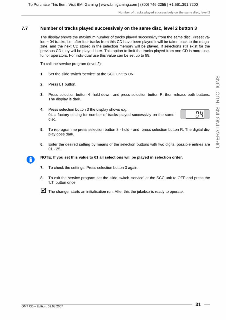
Number of tracks played successively on the same disc, level 2
OMT CD – Edition: 09.08.2007 31
OP
ER
ATI
NG
INS
TRU
CTI
ON
S
7.7 Number of tracks played successively on the same disc, level 2 button 3
The display shows the maximum number of tracks played successivly from the same disc. Preset va-lue = 04 tracks, i.e. after four tracks from this CD have been played it will be taken back to the maga-zine, and the next CD stored in the selection memory will be played. If selections still exist for theprevious CD they will be played later. This option to limit the tracks played from one CD is more use-ful for operators. For individual use this value can be set up to 99.
To call the service program (level 2):
1. Set the slide switch ‘service’ at the SCC unit to ON.
2. Press LT button.
3. Press selection button 4 -hold down- and press selection button R, then release both buttons.The display is dark.
4. Press selection button 3 the display shows e.g.: 04 = factory setting for number of tracks played successivly on the samedisc.
5. To reprogramme press selection button 3 - hold - and press selection button R. The digital dis-play goes dark.
6. Enter the desired setting by means of the selection buttons with two digits, possible entries are01 - 25.
NOTE: If you set this value to 01 all selections will be played in selection order.
7. To check the settings: Press selection button 3 again.
8. To exit the service program set the slide switch ‘service’ at the SCC unit to OFF and press the‘LT’ button once.
" The changer starts an initialisation run. After this the jukebox is ready to operate.
To Purchase This Item, Visit BMI Gaming | www.bmigaming.com | (800) 746-2255 | +1.561.391.7200

Album selection and memory reset by power off, level 2 button 9
OMT CD – Edition: 09.08.200732
OP
ER
ATIN
G IN
STR
UC
TION
S
7.8 Album selection and memory reset by power off, level 2 button 9
By setting the corresponding digit these options are available.
Album selection is possible by entering the disc number followed by 0 0 (track 0 0). All tracks onthe CD are played, starting with the first track. An album is only selectable by coin insertion, if creditsof the 4th bonus level have been obtained or in free play modus (link in row GP from 0 to F on theSCC unit) of the jukebox.
Memory reset feature will cancel remaining credits and selections by power off of the jukebox. Thisoption prevents the jukebox playing preselected tracks from the day before (the jukebox was swit-ched off in the night.).
To change the settings (Service program, level 1):
1. Set the slide switch ‘service’ at the SCC-unit to ON.
2. Press ‘LT’ button.
3. Press selection button 4 -hold down- and press selection button R, then release both buttons.
4. Press selection button 9, the display shows e.g.:# A = digit for memory reset by power off; 1 = ON, 0 = OFF# B = digit for albumplay; 1 = ON, 0 = OFF
5. To change the settings press selection button 9 -hold down- and pressselection button R. The digital display goes dark.
6. Enter the desired setting with two digits.
7. To check the settings: Press selection button 9 again.
8. To exit the service program set the slide switch ‘service’ at the SCC unit to OFF and press theLT button.
AB
To Purchase This Item, Visit BMI Gaming | www.bmigaming.com | (800) 746-2255 | +1.561.391.7200

Disabling single tracks
OMT CD – Edition: 09.08.2007 33
OP
ER
ATI
NG
INS
TRU
CTI
ON
S
7.9 Disabling single tracks
You can disable up to maxinmum 25 different tracks of different CDs. If somebody selects a disabledtrack the digital display flashes. This shows that this track is not selectable. Note a special peculiarityat playstimulator or BGM operation. The random procedure always selects tracks out of a number of25 per CD. If the random selected track exceeds the number of tracks on the CD the procedurestarts to count from the beginnung of the CD. Result is, if you want to disable e.g. track 8 on a CDwith 17 tracks you also have to disable track 23 on this disc although it does not really exist.
To disable tracks (service program level 2):
1. Set the slide switch ‘Service’ at the SCC-unit to ON.
2. Press ‘LT’ button.
3. Press selection button 4 -hold down- and press selection button R, then release both buttons.
4. Press selection button 4 the display shows e.g.:# On CD no. 15 track 08 is disabled.# Each operation of selection button 4 indicates the next disab-
led track, maximum 25 tracks.# After having reached the last disabled track, the first one is in-
dicated again. If the display shows 0000 after the first button operation no track is disabled.
5. To programme: Press selection button 4 -hold down- and press selection button R. The digitaldisplay goes dark.
6. Enter at first the CD number to be disabled followed by the track number (total four digits).
7. To disable the next CD/track, press selection button 4 several times until display shows 0 0 0 0.
8. Press selection button 4 again -hold down- and press selection button R. The digital displaygoes dark.
9. Then enter CD and track to be disabled. Continue programming for the next track to be disabledwith step 7.
10. To check the diabled tracks: Press selection button 4 again (up to 25 times, for 25 disabledtracks).
To enable a disabled track:When a track is indicated, press button 4 -hold down- and press selection button R and enter first thenumber of the CD followed by 0 0.
To enable all disabled tracks:Press selection button 4 -hold down- and press selection button R. Then enter 0 0 0 0 (4 times 0).
" To exit the service program set the slide switch ‘service’ at the SCC unit to OFF and press theLT button.
CD number tracknumber
To Purchase This Item, Visit BMI Gaming | www.bmigaming.com | (800) 746-2255 | +1.561.391.7200

Retrieval of least popular discs (flops), level 1 button 0
OMT CD – Edition: 09.08.200734
OP
ER
ATIN
G IN
STR
UC
TION
S
8 Data retrievalThe data retrieval memory stores data only if the plug ‘ME-MORY’ is always in the position ON (on the RH side of the SCCunit).
You can read out statistical data in the service program level 1over the display.
1. Set the slide switch ‘Service’ at the SCC-unit to ON.
2. Press ‘LT’ button.
8.1 Retrieval of least popular discs (flops), level 1 button 0
1. Press selection button 0 once.# At first the least played CD is shown. The last two digits are simply a code confirming the
least played status. The display shows alternately the disc number and the number of plays e.g.:
# If the counter shows 0 0 0 0, this means the disc has not been played. Press selection but-ton 0 to continue the process for the second least played disc, and so on. At first the CD with the lowest number of plays will be displayed. Press button 0 again, the display shows the CD with the second lowest number of plays etc. If the calculation needs a little longer a ‘1’ scrolls starting from RH. digit over the display.
2. To cancel the procedure press selection button R.
8.2 Top Tunes, level 1 button 1
1. Press selection button 1 once.# The display shows alternately the number of the most played CD and the number of plays.
For example:
Only 60 selections per CD can be stored in the memory. If a CD has been played more than 60 ti-mes all the other values will be decreased by 1. The displayed values are only relative.
Press selection button 1 to continue the process for the second most played CD, and so on.
The most frequently played track will also be displayed as HIT OF THE HOUSE in normal operatingmode.
MemoryON
OFFMemory
0040264
P8
P5
P6 16
15
18
B1
6543210
1245
T11020
+B
T
M LT
CD no. 66 played twice
CD no. 3 played 53 times
To Purchase This Item, Visit BMI Gaming | www.bmigaming.com | (800) 746-2255 | +1.561.391.7200

Cash box contents, level 1 button 2
OMT CD – Edition: 09.08.2007 35
OP
ER
ATI
NG
INS
TRU
CTI
ON
S
8.3 Cash box contents, level 1 button 2
1. Press selection button 2 once. Digital display shows the cash box contents in basic units; basicunits being the value of the lowest coin.
2. To cancel the procedure press selection button R.
8.4 Total number of plays, level 1 button 3
1. Press selection button 3 once. Display shows the total number of plays since last reset (maxi-mum 9999).
2. To cancel the procedure press selection button R.
8.5 CLEAR ALL counters (reset to 0 0 0 0), level 1 button 3 + reset
1. Press selection button 3 -hold down- and press selection button R (reset).# The counters belonging to the buttons 0 to 3 (least popular disc, most popular disc, cash
box and total plays) are cleared and reset to 0 0 0 0.# The sequence of top discs is for the time being 01, 02, 03, 04 etc.# After leaving the service program the jukebox initializes it-
self, during this procedure the compartments in the maga-zines will be counted. At the end of the initialization the display should show either 0 0 0 0 for 100 CD carrier or 0 0 5 0 for 50 CD carrier.
2. To exit the service program first set service switch to OFF andthen press the LT button.
8.6 Memory of not playable CDs, level 1 button 6
Careful handling of the CDs does not completely exclude that CDs may be damaged in differentways. Possibly the player would interrupt this CD at each selection. The S&CC provides a watch dogfunction which finds and memorizes these difficulties to play. The S&CC unit can store the numbersof up to six not playable CDs. Once a CD is registered every new try will be counted. So it is possibleto find out defective discs and exchange these for new ones.
1. Press selection button 6, the display shows flashing:# 1 means first defective CD
then e.g.# A = CD number# B = NUMBER of times the CD was not playable or interrupted
2. Press selection button 6 to display the next not playable CD, etc. Afterdisplaying the 6th not playable CD and pressing selection button 6 againthe display starts with the first one again.
3. To CLEAR this memory press selection button 6 -hold down- and press selection button R.
4. To exit the service program, first set service switch to OFF and then press LT button.
AB
To Purchase This Item, Visit BMI Gaming | www.bmigaming.com | (800) 746-2255 | +1.561.391.7200

Device description of the amplifier K99
OMT CD – Edition: 09.08.200736
FIELD
SE
RV
ICE
MAN
UA
L
9 Amplifier K99
9.1 Device description of the amplifier K99
The amplifier K99 is optimised for universal use in Deutsche Wurlitzer GmbH music machines. Greatimportance had been attached for an easy handling and stand alone function without the S&CC unit.The output power is designed for the typical used internal speakers at Deutsche Wurlitzer GmbHmachines, under normal circumstances reaching an impeccable volume level.
Standard equipment:
! Hybrid power stage technology, short circuit and over temperature protected
! 2 inputs (stereo): CD and tape
! 1 mono input for optional micro kit
! Volume control with 2 pots onboard
! Volume control possible with pots and / or IR at the same time. The pot used at last determinesthe volume.
! Bass and treble control with pots
! BGM volume reduction, controllable with pot
! Automatic volume correction (AVC), switchable
! 2 channel operation switchable, RH = internal speakers, LH = external speakers
! Status display with 7segment display
! Independent controllable RCA output to connect external amplifiers
! For use with the old and the new changer mechanism.
Optional:
! Remote control with large distance range. Functions: track selection / volume chan. 1 / volumechan. 2 / mute (toggle) / cancel
! Volume control with two pots in the wired remote box accessible from the machine rear wall, orexternal. Cancel button and mute button (with toggle function).
! Output transformer
! Microphone kit
9.2 Technical data
General USA / Canada
Supply 100v - 240v 117v
Mains frequency 50cps - 60cps 60cps
Input voltage CD typ. 1.2v typ. 1.2v
Input voltage tape 300mv 300mv
Output voltage pre amplifier <=1veff <=1veff
Output power 2 x 55w (rms) 2 x 55w (rms)
Output impedance min. 4ohm min. 4ohm
Transmission range 20cps - 20,000cps 20cps - 20,000cps
Distorsion factor < 1% < 1%
Noise level depending on the adjusted volume of the jukebox loudness levels of more than 70 dB(A) can be reached.
To Purchase This Item, Visit BMI Gaming | www.bmigaming.com | (800) 746-2255 | +1.561.391.7200

Verification of power voltage
OMT CD – Edition: 09.08.2007 37
FIE
LD S
ER
VIC
E M
AN
UA
L
9.3 Verification of power voltage
The voltage settings are marked onthe cover plate of the mains trans-former. Machines for USA are set to117V. They have a special trans-former according to UL standardwhich is not adjustable. Jukeboxes“UNI-Pack” are shipped in 230V set-ting. This is marked on the machinelabel inside of the door. If the voltagesetting is not clear the transformercover plate has to be removed. Themains fuse (T3.15A) is located on theleft bottom side inbetween the threeterminals for the bill acceptor, the ex-ternal mains switch and the fluores-cent lamps.
Loosen the four screws to remove thecover plate (small arrows).
ATTENTION! Always remove power plug before opening transformer cover plate. Neverattempt any intervention to these parts unless qualified!
The position of the two plug connectors on the transformer terminals 1 to 9 (primary side) indicatesthe current voltage setting. The following combinations are possible:
240V = 1 - 9
230V = 1 - 8
220V = 2 - 9
210V = 2 - 8
117V = 1 - 6
100V = 2 - 6
Notice that these settings cannot bemade on machines produced accord-ing to UL standard.
NOTE: Never connect the fluorescentsupply to other contact.
If you intend to change the power volt-age for a higher voltage (e.g. from117V to 230V) it is better to use asubtransformer for the fluorescentlamps or change the ballast accordingto the used voltage (e.g. for 230V).
NetzsicherungMains Fuse210-240V - T 4A100-117V - F 6A
LeuchtstofflampenFluorescent Lamps
230V / 117V
Vers
tärk
er
Am
plif
ier
Externer HauptschalterExternal Mains switch
Schein-annehmerBill-acceptor
AchtungVor A nahme er appe en Netzsteckerziehen
arningShock hazar o not open
ur Beachtung Nur Sicherungen mitgleicher r e un gleichem erterwen en, um Schä en zu ermei en
aution To re uce the risk of firereplace onl with same t p an rating fuses
Netzspannung50/60 Hz
Mains Voltage50/60 cps
240
230
220
210
117
100
Netzsicherung/Mains Fuse
210-240V - T3,15A100-117V - F6A
Deutsche Wurlitzer GmbH
To Purchase This Item, Visit BMI Gaming | www.bmigaming.com | (800) 746-2255 | +1.561.391.7200

Position of fuses and plug connectors
OMT CD – Edition: 09.08.200738
FIELD
SE
RV
ICE
MAN
UA
L
9.4 Position of fuses and plug connectors
Usually the jukeboxes are fittedwith fuses of DIN 41571 (5x20mm) slow blow or medium blow.Slow blow fuses of DIN standardbear the letter T (T = ”Träge”) e.g.T 4/250 means T = slow blow, 4amps, 250 V maximum operatingvoltage. Which fuses have to fit inis printed on the power transformercover. Fast blow fuses (F = Flink)are unsuitable for the jukebox.
The fuse holders on the amplifierP.C.B. are also capable to holdfuses of 6x32 mm size.
You will find the fuses behind theamplifier cover plate. To removethe plate first unplug the cablecoming from the mains trans-former. Next lose slightly both nutson top of the amplifier accessible through the holes in the cover plate (arrows). To remove the platefirst take the bottom side out of its hinges and then the top side.
Connection plan of the plug terminals:! 1P09 - mechanism, SCC unit! 1P06A - option! 1P06B - option! 2LP04 - external speakers, LH! 2P04 - external speakers, ground! 2RP04 - external speakers, RH! 2P12 - Internal speakers! 1P04 - CD sub transformer, CD player! 1P03 - bubble tubes
Fuse FailureMain fuse T 3,15,res. F6 A for 110/117 V. No illumination, machine completely dead. Fuse F1: T4A supply 30V ~ The digital digit on the CD-control is dark. Power sup-
ply for CD player and control unit is interrupted. Credit circuit via LED M is interrupted. If credits are still in memory or free play is programmed; a CD will be placed on turntable but is not spinning.
Fuse F2: T4A supply 26V ~Fuse F3: T4A supply 26V ~
The colour tubes of the One More Time do not rotate, the heating of the bubble tubes is off - no bubbles will appear. Possibly defect of the power stage of the amp-lifier.
Fuse F4: T4A supply +12 V= SCC unit dead - digital display dark (except red LED M still lighting up on coin insertion). The LEDs K and Z on the SCC unit are dark. No initialisations run after power ON. The status display on the amplifier is dark.
CAUTIONTO REDUCETHE RISKOF FIRE REPLACE ONLYWITH SAMETYPE ANDRATING FUSE
Bass Treble BGM
M
S
ONO
TEREO
ANAL HANNEL
TEREO
2-K / 2-C
S
SF
ICHERUNG
USEF1 - F4
100-240V50Hz/60Hz
117 V60Hz
3,0 AMP250 V ACSLOW BLOW
T 4 A
30V~AC
F1
26V~AC
F2
26V~AC
F3
12V=DC
F4
I LNTERNER AUTSPRECHER
NTERNAL PEAKERI S
OP
TIO
N
OP
TIO
N
RL
EL
ES
8/
80
W
XT
ER
NE
RA
UT
SP
RE
CH
ER
XT
ER
NA
LP
EA
KE
R
W
CD-TCD-T
RAFO
RANSFORMER
B -TUBBLE UBES
NT
ETZTRAFO
RANSFORMER
EERWEITERUNG
XTENSIONF
R CERNREGLER
EMOTE- ONTROL
RS
232
BG
M
IR
IR
NF
RA
RO
T-E
GL
ER
NF
RA
RE
D-
EM
OT
E
A OL
R
US
GA
NG
UT
PU
T
EC
DI
CD
LR
ING
AN
G
NP
UT
EE
300m
VX
TR
A
XT
RAE
300m
VI
LR
ING
AN
G
NP
UT
MM
IKR
OF
ON
ICR
OP
HO
NE
MECHANIK
MECHANISM
D AR C
ECKEL BNEHMEN
EMOVE OVER
D AR C
ECKEL BNEHMEN
EMOVE OVER
IC 1
ntern
hannel
EC
xtern
hannel 2
Verstärker K 99 0056041
Amplifier K 99 C-UL 00584841P09
1P06B
2P04
2LP04
2RP04
2P12
1P04
1P03
1P06A
AVCRS232
MICRO
TAPE
MUTE
A / DNZEIGE ISPLAY
BGM
ok.
S / SCHALTER WITCHES
A /OUS FF
A /OUS FF
E /OIN N
E /OIN N
A
A
VC
VC
MODESTEREO 2-K /2CANAL HANNEL
INPUTCD TAPE
BGM
1
1
3
5
2
2
4
6
SEPARATE
NORMAL
AUTO
VOLUME
RS232
MUTE
HIGH LOW
PARALLEL
SERVICE
AUS/OFF
To Purchase This Item, Visit BMI Gaming | www.bmigaming.com | (800) 746-2255 | +1.561.391.7200

The first power ON
OMT CD – Edition: 09.08.2007 39
FIE
LD S
ER
VIC
E M
AN
UA
L
9.5 The first power ON
The mains switch is located at the rearside of the amplifier and thus it is onthe rear side of the jukebox. For wall-boxes it is possible to connect an ex-ternal mains switch to the amplifieraccessible then from the side. In posi-tion ‘I’ jukebox and amplifier areswitched on.
Up to approx. 1 sec. after power onrandom segments of the status displaywill light. Followed by displaying theversion number of the amplifier soft-ware (1.0 or higher). Then the bottomsegment for “ok.” and the upper seg-ment for MUTE will light. The amplifieris now in STANDBY MODE. Depend-ing on other enabled options moresegments may light as well (e.g.AVC).
9.6 Volume control
You can control the volume of thejukebox from different points at thesame time:
! With the pots Vol. 1 and Vol. 2 onthe amplifier.
! With an optional connectable IR re-mote control.
! With the pots of the control box atthe rear side of the jukebox.
The device from which the volume ischanged determines it.
The volume control unit can be takenout and may be mounted at anotherplace as a remote control. Its cablemay be extended as required with anykind of wire. The voltages of the con-trol wires are 5V DC.
The control box has two volume knobs (Intern / Channel 1 and Extern / Channel 2). In position”Stereo” the knob “Intern / Channel 1” is effective for the internal speakers. The knob Extern / Chan-nel 2 is controlling the volume of the RCA outputs for an optional external amplifier. In DIP switch po-sition ”2 Channel” the channels 1 (RH) and 2 (LH) are controlled separately.
ATTENTION! The pots Vol. 1 and Vol. 2 on the amplifier are not effective if the wire controlbox is connected.
CAUTIONTO REDUCETHE RISKOF FIRE REPLACE ONLYWITH SAMETYPE ANDRATING FUSE
Bass Treble BGM
M
S
ONO
TEREO
ANAL HANNEL
TEREO
2-K / 2-C
S
SF
ICHERUNG
USEF1 - F4
100-240V50Hz/60Hz
117 V60Hz
3,0 AMP250 V ACSLOW BLOW
T 4 A
30V~AC
F1
26V~AC
F2
26V~AC
F3
12V=DC
F4
I LNTERNER AUTSPRECHER
NTERNAL PEAKERI S
OP
TIO
N
OP
TIO
N
RL
EL
ES
8/
80
W
XT
ER
NE
RA
UT
SP
RE
CH
ER
XT
ER
NA
LP
EA
KE
R
W
CD-TCD-T
RAFO
RANSFORMER
B -TUBBLE UBES
NT
ETZTRAFO
RANSFORMER
EERWEITERUNG
XTENSIONF
R CERNREGLER
EMOTE- ONTROL
RS
23
2
BG
M
IR
IR
NF
RA
RO
T-E
GLE
R
NF
RA
RE
D-
EM
OT
E
A OL
R
US
GA
NG
UT
PU
T
EC
DI
CD
LR
ING
AN
G
NP
UT
EE
30
0m
VX
TR
A
XT
RAE
30
0m
VI
LR
ING
AN
G
NP
UT
MM
IKR
OF
ON
ICR
OP
HO
NE
MECHANIK
MECHANISM
D AR C
ECKEL BNEHMEN
EMOVE OVER
D AR C
ECKEL BNEHMEN
EMOVE OVER
S / SCHALTER WITCHES
A /OUS FF
A /OUS FF
E /OIN N
E /OIN N
AVC
MODESTEREO 2-K /2CANAL HANNEL
INPUTCD TAPE
BGM
1
1
3
5
2
2
4
6
IC 1
ntern
hannel
EC
xtern
hannel 2
Verstärker K 99 0056041
Amplifier K 99 C-UL 0058484
A / DNZEIGE ISPLAY
AVC
RS232MICRO
TAPE
MUTE
BGM
ok.
AVC
S232MICRO
TAPE
MUTE
BGM
ok.
CAUTIONTO REDUCETHE RISKOF FIRE REPLACE ONLYWITH SAMETYPE ANDRATING FUSE
Bass Treble BGM
M
S
ONO
TEREO
ANAL HANNEL
TEREO
2-K / 2-C
S
SF
ICHERUNG
USEF1 - F4
100-240V50Hz/60Hz
117 V60Hz
3,0 AMP250 V ACSLOW BLOW
T 4 A
30V~AC
F1
26V~AC
F2
26V~AC
F3
12V=DC
F4
I LNTERNER AUTSPRECHER
NTERNAL PEAKERI S
OP
TIO
N
OP
TIO
N
RL
EL
ES
8/80
W
XT
ER
NE
RA
UT
SP
RE
CH
ER
XT
ER
NA
LP
EA
KE
R
W
CD-TCD-T
RAFO
RANSFORMER
B -TUBBLE UBES
NT
ETZTRAFO
RANSFORMER
EERWEITERUNG
XTENSIONF
R CERNREGLER
EMOTE- ONTROL
RS
232
BG
M
IR
IR
NF
RA
RO
T-E
GL
ER
NF
RA
RE
D-
EM
OT
E
A OL
R
US
GA
NG
UT
PU
T
EC
DI
CD
LR
ING
AN
G
NP
UT
EE
300m
VX
TR
A
XT
RAE
300m
VI
LR
ING
AN
G
NP
UT
MM
IKR
OF
ON
ICR
OP
HO
NE
MECHANIK
MECHANISM
D AR C
ECKEL BNEHMEN
EMOVE OVER
D AR C
ECKEL BNEHMEN
EMOVE OVER
IC 1
ntern
hannel
EC 2
xtern
hannel
Verstärker K 99Amplifier K 99 C-UL
AVCRS232
MICRO
TAPE
MUTE
A / DNZEIGE ISPLAY
BGM
ok.
S / SCHALTER WITCHES
A /OUS FF
A /OUS FF
E /OIN N
E /OIN N
A
A
VC
VC
MODESTEREO 2-K /2CANAL HANNEL
INPUTCD TAPE
BGM
1
1
3
5
2
2
4
6
SEPARATE
NORMAL
AUTO
VOLUME
RS232
MUTE
HIGH LOW
PARALLEL
SERVICE
AUS/OFF
To Purchase This Item, Visit BMI Gaming | www.bmigaming.com | (800) 746-2255 | +1.561.391.7200

The infrared remote control
OMT CD – Edition: 09.08.200740
FIELD
SE
RV
ICE
MAN
UA
L
9.7 The infrared remote control
As desired an infrared remote control will be installedfrom factory or can be delivered as conversion kit (partno. 0058809). If it has been installed the hand transmitteris located in the cashbox.
If credit is given or free play is programmed a CD can beselected with the buttons 0 to 9 and R.
Double button functions as required in the service pro-grams (i.e. press button 5 -hold down- and press buttonR), are impossible. For this you only can use the key-board of the jukebox.
You can control the volume by means of the buttons +and -. In stereo mode the internal +/- buttons control thevolume of the internal speakers. The external +/- buttonscontrol the volume of the K99 RCA jacks for an optionalexternal amplifier. In 2-channel mode you can control theexternal speakers by the buttons + and - of the externalchannel.
Beam the jukebox directly if possible.
You can connect the wire remote control box as well.
The power-on volume level is always set by the channel 1and 2 pots on the amplifier or on the control box (if con-nected).
Batteries will be delivered. Necessary are 4 micro cellstype LR03 (AAA).
To open the battery compartment move the cover likeshown in the picture.
Needed battery type and position of the batteries in thehand transmitter are shown on the casing.
Part no. of the hand transmitter: 0059745.
RCS-K
No.: 0059745
SELECTION
1 2 3
4 5 6 RESET
POWER
OPTION
7 8 9
0
- +
- +
BATTERY:
IEC LR03(AAA)
+
+
+
+
CANCEL MUTE
VOLUME
INTERNCHANNEL 1
EXTERNCHANNEL 2
selection buttons
music control buttons
battery type LR03 (AAA)
position ofthe batteries
To Purchase This Item, Visit BMI Gaming | www.bmigaming.com | (800) 746-2255 | +1.561.391.7200

Treble and bass control
OMT CD – Edition: 09.08.2007 41
FIE
LD S
ER
VIC
E M
AN
UA
L
9.8 Treble and bass control
You can control the sound with the knobsbass and treble on the amplifier.
9.9 Automatic volume correction
The AVC sets CDs with different volume levels to anequal level. The level of CDs with a high level will be re-duced; the level of low-levelled CDs will be increased.This control works rather slow to save the dynamic rangeof the track.
You can enable the correction with the DIP switch “AVC”(the 3rd swich of the 6 sw. group). Default is AVC disa-bled.
With the second DIP switch of the 6 sw. group you canreduce the intensity of the volume correction.
9.10 Background Music - volume attenuation
In the BGM (Back Ground Music) mode the reproductionvolume will be reduced by a certain factor.
The signal “BGM” pin 1 plug brown of the SCC unit con-trols this function. You also can switch on “BGM” bymeans of the DIP switch “BGM” for test purposes. TheRH bottom segment of the status display on the amplifierindicates “BGM active”. You can adjust the volume atten-uation with the pot “BGM”, as long as it is active.
CAUTIONTO REDUCETHE RISKOF FIRE REPLACE ONLYWITH SAMETYPE ANDRATING FUSE
Bass Treble BGM
M
S
ONO
TEREO
ANAL HANNEL
TEREO
2-K / 2-C
S
SF
ICHERUNG
USEF1 - F4
100-240V50Hz/60Hz
117 V60Hz
3,0 AMP250 V ACSLOW BLOW
T 4 A
30V~AC
F1
26V~AC
F2
26V~AC
F3
12V=DC
F4
I LNTERNER AUTSPRECHER
NTERNAL PEAKERI S
OP
TIO
N
OP
TIO
N
RL
EL
ES
8/80
W
XT
ER
NE
RA
UT
SP
RE
CH
ER
XT
ER
NA
LP
EA
KE
R
W
CD-TCD-T
RAFO
RANSFORMER
B -TUBBLE UBES
NT
ETZTRAFO
RANSFORMER
FR C
ERNREGLER
EMOTE- ONTROL
RS
232
BG
M
IR
IR
NF
RA
RO
T-E
GLE
R
NF
RA
RE
D-
EM
OT
E
A OL
R
US
GA
NG
UT
PU
T
EC
DI
CD
LR
ING
AN
G
NP
UT
EE
300m
VX
TR
A
XT
RAE
300m
VI
LR
ING
AN
G
NP
UT
MM
IKR
OF
ON
ICR
OP
HO
NE
MECHANIK
MECHANISM
D AR C
ECKEL BNEHMEN
EMOVE OVER
D AR C
ECKEL BNEHMEN
EMOVE OVER
IC 1
ntern
hannel
EC 2
xtern
hannel
Verstärker K 99Amplifier K 99 C-UL
AVCRS232
MICRO
TAPE
MUTE
A / DNZEIGE ISPLAY
BGM
ok.
S / SCHALTER WITCHES
A /OUS FF
A /OUS FF
E /OIN N
E /OIN N
A
A
VC
VC
MODESTEREO 2-K /2CANAL HANNEL
INPUTCD TAPE
BGM
1
1
3
5
2
2
4
6
SEPARATE
NORMAL
AUTO
VOLUME
RS232
MUTE
HIGH LOW
PARALLEL
SERVICE
AUS/OFF
ERWEITERUNG
EERWEITERUNG
XTENSION
Bass Treble BGM
ERWEITERUNG
XTENSIONF
R CERNREGLER
EMOTE- ONTROL
RS
232
IR
IR
NF
RA
RO
T-E
GLE
RN
FR
AR
ED
-E
MO
TE
IC 1
ntern
hannel
EC
xtern
hannel 2
AVCRS232
MICRO
TAPE
MUTE
A / DNZEIGE ISPLAY
BGM
ok.
S / SCHALTER WITCHES
A /OUS FF
A /OUS FF
E /OIN N
E /OIN N
A
A
VC
VC
MODESTEREO 2-K /2CANAL HANNEL
INPUTCD TAPE
BGM
1
1
3
5
2
2
4
6
SEPARATE
NORMAL
AUTO
VOLUME
RS232
MUTE
HIGH LOW
PARALLEL
SERVICE
AUS/OFF
Bass Treble BGM
EERWEITERUNG
XTENSIONF
R CERNREGLER
EMOTE- ONTROL
RS
232
IR
IR
NF
RA
RO
T-E
GLE
RN
FR
AR
ED
-E
MO
TE
IC 1
ntern
hannel
EC
xtern
hannel 2
AVCRS232
MICRO
TAPE
MUTE
A / DNZEIGE ISPLAY
BGM
ok.
S / SCHALTER WITCHES
A /OUS FF
A /OUS FF
E /OIN N
E /OIN N
A
A
VC
VC
MODESTEREO 2-K /2CANAL HANNEL
INPUTCD TAPE
BGM
1
1
3
5
2
2
4
6
SEPARATE
NORMAL
AUTO
VOLUME
RS232
MUTE
HIGH LOW
PARALLEL
SERVICE
AUS/OFF
To Purchase This Item, Visit BMI Gaming | www.bmigaming.com | (800) 746-2255 | +1.561.391.7200

External speaker connection
OMT CD – Edition: 09.08.200742
FIELD
SE
RV
ICE
MAN
UA
L
9.11 External speaker connection
The amplifier can operate in two differ-ent modes. The normal operationmode reproduces the music in normalstereo sound. So external speakerscan be added to each channel.The so-called 2-Channel mode usesboth stereo channels like separatemono amplifiers so that the sound canbe reproduced in different rooms butthen in mono only.The amplifier may not be loaded withmore than 4 ohms per channel (lessohms means more load!). On an over-load it switches itself off. After a cer-tain cool down time it switches itselfon. So if you do not eliminate the rea-son for the overload the amplifier pro-duces continuously volume dropouts.The impedance of all external speak-ers per channel in ”Stereo” modeshould not be less than 4 ohms.
The amplifier applies approx. 55 watts(rms on max. 1% dist.) on a 4 ohmsspeaker per channel, 18 watts to a 12ohms speaker and approx. 9 watts toa 24 ohms speaker. That means, thate.g., a 12 ohms speaker connected tothe external channel at Dual Channeloperation must be a type of at least 18Watts, otherwise the speaker is indanger of destruction at higher vol-umes. Note that speaker groups like inhi-fi boxes may have, at certain fre-quencies, impedance much lower thantheir rating. Make sure that all speak-ers are connected in correct polarity.
Connect external speakers to the screw terminals on the LH amplifier side.
Position of the Stereo - Mono DIP switch (1), the modeswitch in the 6 sw.group (2), the stereo - 2 channelswitch (3) and the external speaker terminals (4).
CAUTIONTO REDUCETHE RISKOF FIRE REPLACE ONLYWITH SAMETYPE ANDRATING FUSE
Bass Treble BGM
M
S
ONO
TEREO
ANAL HANNEL
TEREO
2-K / 2-C
S
SF
ICHERUNG
USEF1 - F4
100-240V50Hz/60Hz
117 V60Hz
3,0 AMP250 V ACSLOW BLOW
T 4 A
30V~AC
F1
26V~AC
F2
26V~AC
F3
12V=DC
F4
I LNTERNER AUTSPRECHER
NTERNAL PEAKERI S
O O
PT
ION
PT
ION
RL
EL
ES
8/
80
W
XT
ER
NE
RA
UT
SP
RE
CH
ER
XT
ER
NA
LP
EA
KE
R
W
CD-TCD-T
RAFO
RANSFORMER
B -TUBBLE UBES
NT
ETZTRAFO
RANSFORMER
EERWEITERUNG
XTENSIONF
R CERNREGLER
EMOTE- ONTROL
RS
23
2
BG
M
IR
IR
NF
RA
RO
T-E
GLE
R
NF
RA
RE
D-
EM
OT
E
A OL
R
US
GA
NG
UT
PU
T
EC
DI
CD
LR
ING
AN
G
NP
UT
EE
30
0m
VX
TR
A
XT
RAE
30
0m
VI
LR
ING
AN
G
NP
UT
MM
IKR
OF
ON
ICR
OP
HO
NE
MM
ECHANIK
ECHANISM
D AR C
ECKEL BNEHMEN
EMOVE OVER
D AR C
ECKEL BNEHMEN
EMOVE OVER
AVCRS232
MICRO
TAPE
MUTE
A / DNZEIGE ISPLAY
BGM
ok.
S / SCHALTER WITCHES
A /OUS FF
A /OUS FF
E /OIN N
E /OIN N
A
A
VC
VC
MODESTEREO 2-K /2CANAL HANNEL
INPUTCD TAPE
BGM
1
1
3
5
2
2
4
6
IC 1
ntern
hannel
EC
xtern
hannel2
Verstärker K 99 0056041
Amplifier K 99 C-UL 0058484
1
3
4
2
SEPARATE
NORMAL
AUTO
VOLUME
RS232
MUTE
HIGH LOW
PARALLEL
SERVICE
AUS/OFF
DIP switch “Mode”, slide switch Stereo-2channel and Mono-Stereo switch
in position STEREO
R
L TerminalL-extern
TerminalR-extern
2channel-stereo
slide switch
DIP switch
2C
“Mode”
Stereo
Normal operation mode (Stereo)
NetzsicherungMains Fuse210-240V - T 4A100-117V - F 6A
LeuchtstofflampenFluorescent Lamps
230V / 117V
Ve
rstä
rke
rA
mp
lifie
r
Externer HauptschalterExternal Mains switch
Schein-annehmerBill-acceptor
Achtung!Vor Abnahme der Kappe den Netzsteckerziehen!
Warning!Shock hazard! Do not open!
Zur Beachtung: Nur Sicherungen mitgleicher Größe und gleichem Wertverwenden, um Schäden zu vermeiden.
Caution: To reduce the risk of firereplace only with same typ and rating fuses.
Netzspannung50/60 Hz
Mains Voltage50/60 cps
240
230
220
210117
100
CAUTIONTO REDUCETHE RISKOF FIRE REPLACE ONLYWITH SAMETYPE ANDRATING FUSE
Bass Treble BGM
M
S
ONO
TEREO
ANAL HANNEL
TEREO
2-K / 2-C
S
S
F
ICHERUNG
USEF1 - F4
100-240V
50Hz/60Hz
117 V
60Hz
3,0 AMP250 V ACSLOW BLOW
T 4 A
30V~AC
F1
26V~AC
F2
26V~AC
F3
12V=DC
F4
I LNTERNER AUTSPRECHER
NTERNAL PEAKERI S
OP
TIO
N
OP
TIO
N
RL
EL
ES
8/
80
W
XT
ER
NE
RA
UT
SP
RE
CH
ER
XT
ER
NA
LP
EA
KE
R
W
CD-TCD-T
RAFO
RANSFORMER
B -TUBBLE UBES
NT
ETZTRAFO
RANSFORMER
E
E
RWEITERUNG
XTENSIONF
R CERNREGLER
EMOTE- ONTROL
RS
23
2
BG
M
IR
IR
NF
RA
RO
T-E
GLE
R
NF
RA
RE
D-
EM
OT
E
A OL
R
US
GA
NG
UT
PU
T
EC
DI
CD
LR
ING
AN
G
NP
UT
EE
30
0m
VX
TR
A
XT
RAE
30
0m
VI
LR
ING
AN
G
NP
UT
MM
IKR
OF
ON
ICR
OP
HO
NE
MECHANIK
MECHANISM
D AR C
ECKEL BNEHMEN
EMOVE OVER
D AR C
ECKEL BNEHMEN
EMOVE OVER
AVC
RS232MICRO
TAPE
MUTE
A / DNZEIGE ISPLAY
BGM
ok.
S / SCHALTER WITCHES
A /OUS FF
A /OUS FF
E /OIN N
E /OIN N
AVC
MODESTEREO 2-K /2CANAL HANNEL
INPUTCD TAPE
BGM
1
1
3
5
2
2
4
6
IC 1
ntern
hannel
EC
xtern
hannel 2
Verstärker K 99 0056041
Amplifier K 99 C-UL 0058484
NetzsicherungMains Fuse210-240V - T 4A100-117V - F 6A
LeuchtstofflampenFluorescent Lamps
230V / 117V
Ve
rstä
rke
rA
mp
lifie
r
Externer HauptschalterExternal Mains switch
Schein-annehmerBill-acceptor
Achtung!Vor Abnahme der Kappe den Netzsteckerziehen!
Warning!Shock hazard! Do not open!
Zur Beachtung: Nur Sicherungen mitgleicher Größe und gleichem Wertverwenden, um Schäden zu vermeiden.
Caution: To reduce the risk of firereplace only with same typ and rating fuses.
Netzspannung50/60 Hz
Mains Voltage50/60 cps
240
230
220210
117
100
CAUTIONTO REDUCETHE RISKOF FIRE REPLACE ONLYWITH SAMETYPE ANDRATING FUSE
Bass Treble BGM
M
S
ONO
TEREO
ANAL HANNEL
TEREO
2-K / 2-C
S
SF
ICHERUNG
USEF1 - F4
100-240V50Hz/60Hz
117 V60Hz
3,0 AMP250V ACSLOW BLOW
T 4 A
30V~AC
F1
26V~AC
F2
26V~AC
F3
12V=DC
F4
I LNTERNER AUTSPRECHER
NTERNAL PEAKERI S
OP
TIO
N
OP
TIO
N
RL
EL
ES
8/80
W
XT
ER
NE
RA
UT
SP
RE
CH
ER
XT
ER
NA
LP
EA
KE
R
W
CD-TCD-T
RAFO
RANSFORMER
B -TUBBLE UBES
NT
ETZTRAFO
RANSFORMER
EERWEITERUNG
XTENSIONF
R CERNREGLER
EMOTE- ONTROL
RS
23
2
BG
M
IR
IR
NF
RA
RO
T-
EG
LE
R
NF
RA
RE
D-
EM
OT
E
A OL
R
US
GA
NG
UT
PU
T
EC
DI
CD
LR
ING
AN
G
NP
UT
EE
30
0m
VX
TR
A
XT
RAE
30
0m
VI
LR
ING
AN
G
NP
UT
MM
IKR
OF
ON
ICR
OP
HO
NE
MECHANIK
MECHANISM
D AR C
ECKEL BNEHMEN
EMOVE OVER
D AR C
ECKEL BNEHMEN
EMOVE OVER
AVC
RS232MICRO
TAPE
MUTE
A / DNZEIGE ISPLAY
BGM
ok.
S / SCHALTER WITCHES
A /OUS FF
A /OUS FF
E /OIN N
E /OIN N
AVC
MODESTEREO 2-K /2CANAL HANNEL
INPUTCD TAPE
BGM
1
1
3
5
2
2
4
6
I
C 1
ntern
hannel
E
C
xtern
hannel 2
Verstärker K 99 0056041
Amplifier K 99 C-UL 0058484
+
+
+
++
+
+
+++
Two speakers of 4ohm also representtotal impedance of 8ohm.
4Ω 4Ω 2Ω
2Ω
2Ω
2Ω
To Purchase This Item, Visit BMI Gaming | www.bmigaming.com | (800) 746-2255 | +1.561.391.7200

External amplifier connection
OMT CD – Edition: 09.08.2007 43
FIE
LD S
ER
VIC
E M
AN
UA
L
9.12 External amplifier connection
On the RCA terminals “Ausgang - Output”you can connect an external amplifierwith any power rate. In Stereo mode theoutput level is normally controlled bymeans of the pot for the 2nd channel. Al-ternatively you can set the first DIP switchof the 6 sw. group to ON to couple thisoutput to the normal volume controlknobs (1st channel), so that both amplifi-ers can be controlled together.Connecting an external amplifier in 2-channel mode is not useful.To avoid hum- (earth-) loops try to use anexternal amplifier with ground insulation;it has no earth contacts. If it is impossible(e.g. receivers with cable supply) you canseparate both amps by means of the ground isolator part no. 0053300.The signal of the RCA terminals is also controlled by the settings of bass, treble, BGM, AVC andMute.
9.13 Disabling the internal mute circuit
With the optional BGM-Connector (partno. 0048133) you can connect an exter-nal source to the jukebox. In this case theamplifier should not be muted duringstandby of the jukebox.
Please switch off the internal mute circuitby setting the first DIP switch of the 2 sw.group “Mute” to OFF.
For more information order the DeutscheWurlitzer GmbH technical informationleaflets TI-MA-116.
9.14 Input selector
With the 5th DIP switch of the 6 sw.group you can set either CD or tape inputas active.
CAUTIONTO REDUCETHE RISKOF FIRE REPLACE ONLYWITH SAMETYPE ANDRATING FUSE
Bass Treble BGM
M
S
ONO
TEREO
ANAL HANNEL
TEREO
2-K / 2-C
S
SF
ICHERUNG
USEF1 - F4
100-240V50Hz/60Hz
117 V60Hz
3,0 AMP250 V ACSLOW BLOW
T 4 A
30V~AC
F1
26V~AC
F2
26V~AC
F3
12V=DC
F4
I LNTERNER AUTSPRECHER
NTERNAL PEAKERI S
O O
PT
ION
PT
ION
RL
EL
ES
8/
80
W
XT
ER
NE
RA
UT
SP
RE
CH
ER
XT
ER
NA
LP
EA
KE
R
W
CD-TCD-T
RAFO
RANSFORMER
B -TUBBLE UBES
NT
ETZTRAFO
RANSFORMER
FR C
ERNREGLER
EMOTE- ONTROL
RS
23
2
BG
M
IR
IR
NF
RA
RO
T-E
GLE
R
NF
RA
RE
D-
EM
OT
E
A OL
R
US
GA
NG
UT
PU
T
EC
DI
CD
LR
ING
AN
G
NP
UT
EE
30
0m
VX
TR
A
XT
RAE
30
0m
VI
LR
ING
AN
G
NP
UT
MM
IKR
OF
ON
ICR
OP
HO
NE
MM
ECHANIK
ECHANISM
D AR C
ECKEL BNEHMEN
EMOVE OVER
D AR C
ECKEL BNEHMEN
EMOVE OVER
IC 1
ntern
hannel
EC
xtern
hannel2
Verstärker K 99 0056041
Amplifier K 99 C-UL 0058484
AVCRS232
MICRO
TAPE
MUTE
A / DNZEIGE ISPLAY
BGM
ok.
S / SCHALTER WITCHES
A /OUS FF
A /OUS FF
E /OIN N
E /OIN N
A
A
VC
VC
MODESTEREO 2-K /2CANAL HANNEL
INPUTCD TAPE
BGM
1
1
3
5
2
2
4
6
SEPARATE
NORMAL
AUTO
VOLUME
RS232
MUTE
HIGH LOW
PARALLEL
SERVICE
AUS/OFF
EERWEITERUNG
XTENSION
AVCRS232
MICRO
TAPE
MUTE
A / DNZEIGE ISPLAY
BGM
ok.
S / SCHALTER WITCHES
A /OUS FF
A /OUS FF
E /OIN N
E /OIN N
A
A
VC
VC
MODESTEREO 2-K /2CANAL HANNEL
INPUTCD TAPE
BGM
1
1
3
5
2
2
4
6
SEPARATE
NORMAL
AUTO
VOLUME
RS232
MUTE
HIGH LOW
PARALLEL
SERVICE
AUS/OFF
ERWEITERUNG
AVCRS232
MICRO
TAPE
MUTE
A / DNZEIGE ISPLAY
BGM
ok.
S / SCHALTER WITCHES
A /OUS FF
A /OUS FF
E /OIN N
E /OIN N
A
A
VC
VC
MODESTEREO 2-K /2CANAL HANNEL
INPUTCD TAPE
BGM
1
1
3
5
2
2
4
6
SEPARATE
NORMAL
AUTO
VOLUME
RS232
MUTE
HIGH LOW
PARALLEL
SERVICE
AUS/OFF
EERWEITERUNG
XTENSION
To Purchase This Item, Visit BMI Gaming | www.bmigaming.com | (800) 746-2255 | +1.561.391.7200

Verification of power voltage
OMT CD – Edition: 09.08.200744
FIELD
SE
RV
ICE
MAN
UA
L
10 Amplifier F91The amplifier F91 is the version with higher power out-put (2 x 170 W rms.). Equipped with protection andwatch dog functions described below. The BGMadapter (to attenuate the volume in BGM mode) is in-tegrated. The amplifier is equipped with an automaticvolume control (AVC) to level out different recordinglevels.
In 2-channel mode it is possible to control both chan-nels separately with the IR-remote control.
You can also make selections with the optional infra-red remote control.
10.1 Verification of power voltage
ATTENTION! Always remove power plug before opening transformer cover plate. Neverattempt any intervention to these parts unless qualified.
The power voltage setting is on the cover plate of theF91 transformer. Machines for USA are set to 117 V.Jukeboxes „UNI-Pack“ are shipped in 230 V setting.This is marked on the machine label inside of thedoor. If the voltage setting is not clear the transformercover plate has to be removed.
The mains fuse (T3,15 A, res. T8 A for 117V) is lo-cated near the RH side of the cover plate.
The position of the two plug connectors on the trans-former terminals 1 to 9 (primary side) indicates thecurrent voltage setting. The following combinations are possible:
240V = 1 - 9
230V = 1 - 8
220V = 2 - 9
210V = 2 - 8
117V = 1 - 6
100V = 2 - 6
Never connect the fluorescent supply to othercontacts.
If you intend to change the power voltage to a highervoltage (e.g. from 117V to 230V) it is recommended touse a subtransformer for the flourescent lamps orchange the ballast according to the used voltage (e.g.for 230V).
The power consumption in standby is approx. 146W.With max. volume it is approx. 540W.
Verstärker-Sicherungen
210V - 240V
Si 1/Si 301Si 2/Si 302
Si 102/Si 103Si 100/Si 101
MT 4A T 3,15A
100V - 117V
Si 1/Si 301Si 2/Si 302
T 5A
Si 102/Si 103Si 100/Si 101
T 3A
Zur Beachtung Nur Sicherungen mit gleicher Größe undgleichem Wert verwenden um Schäden zu vermeiden.
Caution: To reduce the risk of fire replace only withsame type and rating fuses.
Achtung!Vor Abnahme der Kappe den Netzsteckerziehen!Attention!Pull power plug before opening protectivelid!
Leuchtstofflampen/Flourescent Lamps
230V / 117V
/ Amplifier FusesNetzspannung
50/60 Hz
Mains Voltage50/60 cps
240230
210
100
220
117
Low Level
BGM
Mic.-Kit
L
R
Line Out
L
R
Input Tape
L
R
Input CD
Amplifier F910039155
BGM Level
R
L
L R
Clipping
Remote
Remote
1
2
4
1
2
4
Tone
off on
Treble
Bass
1
24
8
16
32
1
2
4
8
16
32
Volume
off on
R
L
Mode
Input
CD
Stereo
Tape
2-Kanal
R
L
Verstärker-Sicherungen
210V - 240V
Si 1/Si 301Si 2/Si 302
Si 102/Si 103Si 100/Si 101
MT 4A T 3,15A
100V - 117V
Si 1/Si 301Si 2/Si 302
T 5A
Si 102/Si 103Si 100/Si 101
T 3A
Zur Beachtung Nur Sicherungen mit gleicher Größe undgleichem Wert verwenden um Schäden zu vermeiden.
Caution: To reduce the risk of fire replace only withsame type and rating fuses.
Achtung!Vor Abnahme der Kappe den Netzsteckerziehen!Attention!Pull power plug before opening protectivelid!
Netzsicherung/Mains Fuse
210-240V - T3,15A100-117V - T8A
Leuchtstofflampen/Flourescent Lamps
230V / 117V
/ Amplifier FusesNetzspannung
50/60 Hz
Mains Voltage50/60 cps
240230
210
100
220
117
Loosen the 4 screws to remove cover plate(small arrows)
to amplifier
from mains
1 - 8 = 230V
to flourescent lamps
Ma
ins
vo
lta
ge
-Ne
tzsp
an
nu
ng
24
0V
=1
-9
23
0V
=1
-8
22
0V
=2
-9
21
0V
=2
-8
11
7V
=1
-6
10
0V
=2
-6
Te
mp
era
turw
äch
ter
the
rma
lfu
se
=2
-4
De
uts
ch
eW
url
itze
rG
mb
HT
ran
sfo
rma
tor
00
39
40
2
na
ch
VD
E0
55
15
0/
60
Hz
12
34
56
78
9
1011
1213
1415
1617
18
rbr
gn/bl
or/y
br/r
wt/bk
vi/gy
gn/bl
or/y
br/r
gybk
bk
To Purchase This Item, Visit BMI Gaming | www.bmigaming.com | (800) 746-2255 | +1.561.391.7200

Position of fuses and plug connectors on the power amp board
OMT CD – Edition: 09.08.2007 45
FIE
LD S
ER
VIC
E M
AN
UA
L
10.2 Position of fuses and plug connectors on the power amp board
WARNING! A voltage of approx. +60V res. - 60V applies to the fuse terminals also a certain time af-ter power off. Change the fuses with caution !
Usually the jukeboxes are fitted with fuses of DIN 41571 (5x20 mm) slow blow or medium blow. Slowblow fuses of DIN standard bear the letter T (T = “Träge”) e.g. T 4/250 means T = slow blow, 4amps, 250 V maximum operating voltage. Which fuses have to be used is printed on the powertransformer cover. Fast blow fuses (F = Flink) are unsuitable for the jukebox.
The fuse holders on the amplifier P.C.B. are capable to hold also fuses of 6x32 mm size.
Position of the plug connectorsP12 - jukebox speakers
P 3 - bubble tubes
P16 - power transformer
P 4 - CD sub transformer, CD player
P 9 - mechanism, Selection and Credit Computer
P 6 - option, coin interface
P6A - option
P 7 - service
Fuse FailureMain fuse T 3,15,res. T8 A for 110/117 V. No illumination, machine completely dead.Fuse Si1: T4A (T5A) +70V= L.H. channel power stageFuse Si2: T4A (T5A) -70V= L.H. channel power stage
No sound in the L.H. channel. Speaker relay is not acti-vated, green LED does not light.
Fuse Si301: T4A (T5A) +70V= R.H. ch. power stageFuse Si302: T4A (T5A) -70V= R.H. ch. power stage
No sound in the R.H. channel. Speaker relay is not acti-vated, green LED does not light.
Fuse Si100: T3,15A (T3A) supply -30 V= The jukebox operates normal. The CD2 mechanism does not use this voltage.
Fuse Si101: T3,15A (T3A) supply +30 V= No initialisation run after power ON. Display working. No function.
Fuse Si102: T3,15A (T3A) supply +12 V= SCC unit dead - digital display dark (except red LED M still lighting up on coin insertion).The LEDs K and Z on the SCC unit are dark. No initiali-sation run after power ON.
Fuse Si103: T3,15A (T3A) supply 30V ~ The digital digit on the CD-control is dark. Power supply for CD player and control unit is interrupted. Credit cir-cuit via LED M is interrupted. If credits are still in me-mory or free play is programmed, a CD will placed on turntable but is not spinning. After about one minute the CD is taken back.If no credits in memory, no CD will be taken to turntable, the display is flashing.
P12
P3
P16
P4
P9
P6
P6A
P7
Si1
Si2Si301Si302
Si102Si100 Si101
terminal forexternalspeakers
Si103
To Purchase This Item, Visit BMI Gaming | www.bmigaming.com | (800) 746-2255 | +1.561.391.7200

The first power ON
OMT CD – Edition: 09.08.200746
FIELD
SE
RV
ICE
MAN
UA
L
10.3 The first power ON
The mains switch is located at the bottom left hand rearside of the jukebox. In position ‘I’ jukebox and amplifierare switched on. The amplifier is now in STANDBYMODE:
The yellow ‘Low Level LED’ lights.
The ‘Low Level’ circuit detects low music parts andpauses. It effects the AVC circuit not to raise the audiolevel in music pauses. So disturbing noises will not beheard. This LED may light for short times during play.
The yellow ‘Mute LED’ lights (on the power amp board,only visible after lifting up the pre amp board). It indicatesthat the amplifier is muted.
To avoid power on and other noises, the amplifier outputwill be switched on only during play.
10.4 Pre-settings for volume, bass, treble
After power on of the jukebox or after pressing the button ‘preset’ the levels of volume, bass and tre-ble will be set to basic values. These values can be set with different binary DIP switch combina-tions. The switches are located on the amplifier pre amp board. You can find the recommendedsettings on the amplifier cover.
Low Level
BGM
Mic.-Kit
L
R
Line Out
L
R
Input Tape
L
R
Input CD
Amplifier F910039155
BGM Level
R
L
L R
Clipping
Remote
Remote
1
2
4
1
2
4
Tone
off on
Treble
Bass
1
24
8
16
32
1
2
4
8
16
32
Volume
off on
R
L
Mode
Input
CD
Stereo
Tape
2-Kanal
R
L
Low Level LED
Power stage P.C.B.
MUTE-LED
Low Level
BGM
Mic.-Kit
L
R
Line Out
L
R
Input Tape
L
R
Input CD
Amplifier F910039155
BGM LevelGain
R
L
L R
ClippingP10Remote
P10Remote
P4
1
2412
4
Tone
off on
Treble
Bass
1
248
16
32
1
2
48
1632
Volume
off on
R
L
Mode
Input
CD
Stereo
Tape
2-Kanal
R
L
Tone presetDIP switches
Two redclipping LEDs
Low levelLED, yellow
Mode selectorstereo / 2-channel
Input selectorCD / tape
BGM activeindicatorLED yellow
Volume presetDIP switches Gain pre pots BGM level pots
CD inputterminals
tape / magn. pick upinput terminals
mike kit socket
line outputterminals
Remote controlterminals
1. 2. 3.
4.
5.
6.
7.
8.9.
10.
11.
12.
13.
14.
To Purchase This Item, Visit BMI Gaming | www.bmigaming.com | (800) 746-2255 | +1.561.391.7200

Pre-settings for volume, bass, treble
OMT CD – Edition: 09.08.2007 47
FIE
LD S
ER
VIC
E M
AN
UA
L
10.4.1 Pre-settings for volumeYou can set the basic values for volume in 63 steps(to 2dB) from no up to maximum volume.
On the amplifier front cover you can find 6 DIP-switches (preset value) for each channel. Theseswitches have different values (1, 2 ... to 32). If youadd all the values of the switches in position “ON” youwill get the value for the preset volume.
The recommended factory settings are printed on theamplifier cover (32).
If you change the DIP-switch settings while the juke-box is operating, new settings will be taken over afterhaving pressed the button ‘PRESET’ at the control ter-minal or on IR remote or after power on.
WARNING! If all switches are in position OFF no volume, if all switches are in position ON, the ma-ximum volume appears at power on !
10.4.2 Pre-settings for bass and trebleLike wise the values for bass and treble can be set.However for both channels together.
Verstärker-Sicherungen
210V - 240V
Si 1/Si 301Si 2/Si 302
Si 102/Si 103Si 100/Si 101
MT 4A T 3,15A
100V - 117V
Si 1/Si 301Si 2/Si 302
T 5A
Si 102/Si 103Si 100/Si 101
T 3A
Zur Beachtung Nur Sicherungen mit gleicher Größe undgleichem Wert verwenden um Schäden zu vermeiden.
Caution: To reduce the risk of fire replace only withsame type and rating fuses.
Achtung!Vor Abnahme der Kappe den Netzsteckerziehen!Attention!Pull power plug before opening protectivelid!
Leuchtstofflampen/Flourescent Lamps
230V / 117V
/ Amplifier FusesNetzspannung
50/60 Hz
Mains Voltage50/60 cps
240230
210
100
220
117
Low Level
BGM
Mic.-Kit
L
R
Line Out
L
R
Input Tape
L
R
Input CD
Amplifier F910039155
BGM Level
R
L
L R
ClippingP10Remote
P10Remote
P4
1
24
12
4
Tone
off on
Treble
Bass
1
24
8
16
32
1
2
4
8
1632
Volume
off on
R
L
Mode
Input
CD
Stereo
Tape
2-Kanal
R
L
1
24
8
16
32
1
2
4
8
1632
DIP switches forvolume pre-settings
1
2
4
8
16
32
- switch position ON
0 1 3 5 7 9 11 13 152 4 6 8 10 12 14 16 18 20 22 24 26 28 3017 19 21 23 25 27 29 31 33 35 37 39 41 43 45 47 4932 34 36 38 40 42 44 46 48 50 52 54 56 58 60 6151 53 55 57 59 6362
Preset volume level
va
lue
low high
0%
100%
1
24
12
4
DIP switchesrecommended
settigs
treble
bass
off on
To Purchase This Item, Visit BMI Gaming | www.bmigaming.com | (800) 746-2255 | +1.561.391.7200
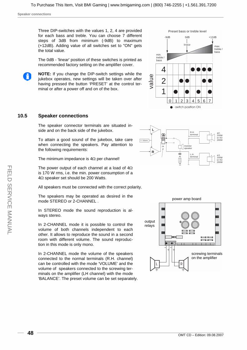
Speaker connections
OMT CD – Edition: 09.08.200748
FIELD
SE
RV
ICE
MAN
UA
L
Three DIP-switches with the values 1, 2, 4 are providedfor each bass and treble. You can choose 7 differentsteps of 3dB from minimum (-9dB) to maximum(+12dB). Adding value of all switches set to "ON" getsthe total value.
The 0dB - 'linear' position of these switches is printed asrecommended factory setting on the amplifier cover.
NOTE: If you change the DIP-switch settings while thejukebox operates, new settings will be taken over afterhaving pressed the button ‘PRESET’ at the control ter-minal or after a power off and on of the box.
10.5 Speaker connections
The speaker connector terminals are situated in-side and on the back side of the jukebox.
To attain a good sound of the jukebox, take carewhen connecting the speakers. Pay attention tothe following requirements:
The minimum impedance is 4Ω per channel!
The power output of each channel at a load of 4Ωis 170 W rms, i.e. the min. power consumption of a4Ω speaker set should be 200 Watts.
All speakers must be connected with the correct polarity.
The speakers may be operated as desired in themode STEREO or 2-CHANNEL .
In STEREO mode the sound reproduction is al-ways stereo.
In 2-CHANNEL mode it is possible to control thevolume of both channels independent to eachother. It allows to reproduce the sound in a secondroom with different volume. The sound reproduc-tion in this mode is only mono.
In 2-CHANNEL mode the volume of the speakersconnected to the normal terminals (R.H. channel)can be controlled with the mode ‘VOLUME’ and thevolume of speakers connected to the screwing ter-minals on the amplifier (LH channel) with the mode‘BALANCE’. The preset volume can be set separately.
1
2
4
- switch position ON
0 1 3 5 72 4 6
va
lue
Preset bass or treble level
-9dB 0dB +12dB
min.treble /bass
max.treble /bass
linear
8100Wor 4200W
8100Wor 4200W
L
R
2K monitorspeaker
+/- Volume
L.H.terminal
R.H.terminal +
_
+
_
L R
- -
++
+ +
power amp board
screwing terminalson the amplifier
outputrelays
To Purchase This Item, Visit BMI Gaming | www.bmigaming.com | (800) 746-2255 | +1.561.391.7200

Speaker connections
OMT CD – Edition: 09.08.2007 49
FIE
LD S
ER
VIC
E M
AN
UA
L
10.5.1 The operating mode STEREOFor normal operation the jukebox is set to the STEREO mode. Both amplifier switches, the modeswitch and the slide switch S1 on the power amplifier board are set to position STEREO.
Example1:Two 8Ω speaker connected in parallelper channel
Example 2:2 times 4 Ω speaker connected in se-ries and in parallel with one 8Ωspeaker
Low Level
BGM
Mic.-Kit
L
R
Line Out
L
R
Input Tape
L
R
Input CD
Amplifier F910039155
BGM Level
R
L
L R
ClippingP10
Remote
P10
Remote
P4
1
2
412
4
Tone
off on
Treble
Bass
R
L
S1
S1
P12
Volume
Mode
Input
CD
Stereo
Tape
2-Kanal
R
mode switch
positionSTEREO
2-channel / Stereoslide switch S1
L
R
2K
+/- Volume
8100W
+
_
8100W
+
_
8100W
+
_
8100W
+
_
monitorspeaker
L.H.terminal
R.H.terminal
2-channel / Stereoslide switch S1
L
R
2K
+/- Volume
8100W
+
_
450W
450W
+
_+
_
8100W
+
_
450W
450W
+
_+
_
monitorspeaker
L.H.terminal
R.H.terminal
2-channel / Stereoslide switch S1
To Purchase This Item, Visit BMI Gaming | www.bmigaming.com | (800) 746-2255 | +1.561.391.7200

Connecting external speakers in operating mode 2-CHANNEL
OMT CD – Edition: 09.08.200750
FIELD
SE
RV
ICE
MAN
UA
L
10.6 Connecting external speakers in operating mode 2-CHANNEL
For 2-CHANNEL operation both amplifier switches, themode switch and the slide switch S1 on the power am-plifier board are set to position 2-CHANNEL.
As the following examples show, in the 2-CHANNELmode it is possible to connect different loads to eachamplifier output. Take care that the min. impedance is4Ω per channel.
Example 1:1st room a speaker of 4Ω200W, 2nd room 4speaker of2Ω 30W connected in series
Example 2:1st room a speaker of 4Ω200W, 2nd room 4speaker of16Ω 50W connected in parallel
Low Level
BGM
Mic.-Kit
L
R
Line Out
L
R
Input Tape
L
R
Input CD
Amplifier F910039155
BGM Level
R
L
L R
ClippingP10Remote
P10Remote
P4
1
2
4
1
2
4
Tone
off on
Treble
Bass
1
2
4
8
16
32
1
2
4
8
16
32
Volume
off on
R
L
Mode
Input
CD
Stereo
Tape
2-Kanal
R
L
Volume
Mode
Input
CD
Stereo
Tape
2-Kanal
R
S1
S1
P12
mode switch
2-channel / stereoslide switch S1
in position 2-channel
L
R
2K monitorspeaker
normalterminal
screwing terminals
230W
230W
+
_+
_
230W
230W
+
_+
_4200W
+
_
+/- Volume
+/- Balance
stereoslide switch
L
R
2K
1650W
1650W
1650W
1650W
+
_
+
_
+
_
+
_
4200W
+
_
+/- Volume
+/- Balance
monitorspeaker
normalterminal
screwingterminals
2-channel /stereo slideswitch
To Purchase This Item, Visit BMI Gaming | www.bmigaming.com | (800) 746-2255 | +1.561.391.7200
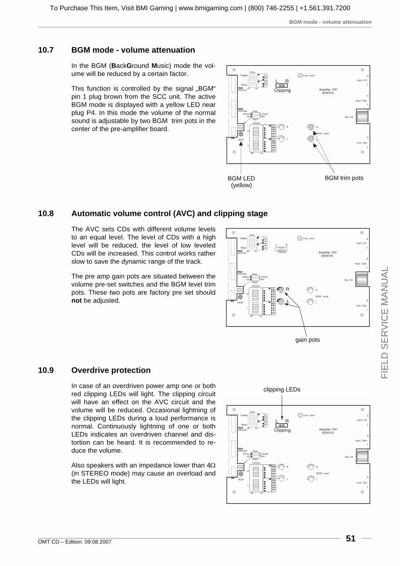
BGM mode - volume attenuation
OMT CD – Edition: 09.08.2007 51
FIE
LD S
ER
VIC
E M
AN
UA
L
10.7 BGM mode - volume attenuation
In the BGM (BackGround Music) mode the vol-ume will be reduced by a certain factor.
This function is controlled by the signal „BGM“pin 1 plug brown from the SCC unit. The activeBGM mode is displayed with a yellow LED nearplug P4. In this mode the volume of the normalsound is adjustable by two BGM trim pots in thecenter of the pre-amplifier board.
10.8 Automatic volume control (AVC) and clipping stage
The AVC sets CDs with different volume levelsto an equal level. The level of CDs with a highlevel will be reduced, the level of low leveledCDs will be increased. This control works ratherslow to save the dynamic range of the track.
The pre amp gain pots are situated between thevolume pre-set switches and the BGM level trimpots. These two pots are factory pre set shouldnot be adjusted.
10.9 Overdrive protection
In case of an overdriven power amp one or bothred clipping LEDs will light. The clipping circuitwill have an effect on the AVC circuit and thevolume will be reduced. Occasional lightning ofthe clipping LEDs during a loud performance isnormal. Continuously lightning of one or bothLEDs indicates an overdriven channel and dis-tortion can be heard. It is recommended to re-duce the volume.
Also speakers with an impedance lower than 4Ω(in STEREO mode) may cause an overload andthe LEDs will light.
Low Level
BGM
Mic.-Kit
L
R
Line Out
L
R
Input Tape
L
R
Input CD
Amplifier F910039155
BGM Level
R
L
L R
ClippingP10Remote
P10Remote
P4
1
2
412
4
Tone
off on
Treble
Bass
1
24
8
16
32
1
2
4
8
16
32
Volume
off on
R
L
Mode
Input
CDStereo
Tape2-Kanal
R
L
BGM LED(yellow)
BGM trim pots
Low Level
BGM
Mic.-Kit
L
R
Line Out
L
R
Input Tape
L
R
Input CD
Amplifier F910039155
BGM Level
R
L
L R
ClippingP10Remote
P10Remote
P4
1
2
412
4
Tone
off on
Treble
Bass
1
24
8
16
32
1
2
4
8
16
32
Volume
off on
R
L
Mode
Input
CDStereo
Tape2-Kanal
R
L
gain pots
Low Level
BGM
Mic.-Kit
L
R
Line Out
L
R
Input Tape
L
R
Input CD
Amplifier F910039155
BGM Level
R
L
L R
ClippingP10Remote
P10Remote
P4
1
2
412
4
Tone
off on
Treble
Bass
1
24
8
16
32
1
2
4
8
16
32
Volume
off on
R
L
Mode
Input
CDStereo
Tape2-Kanal
R
L
clipping LEDs
To Purchase This Item, Visit BMI Gaming | www.bmigaming.com | (800) 746-2255 | +1.561.391.7200

Overload protection
OMT CD – Edition: 09.08.200752
FIELD
SE
RV
ICE
MAN
UA
L
10.10 Overload protection
The power amplifier is provided with an overload pro-tection circuit.
While the CD is playing two green LEDs indicate thatthe speaker output relays are activated. If one of theseLEDs is dark during play and no sound appears anoverload of the power amp stage has occurred, whichis for example caused by a short circuit in the connec-tion wires to the external speakers.
An additional internal watch dog circuit checks that theaudio signal contains no DC Voltages and no highsublow frequencies. It also indicates that the load limi-tation cut off has been reached. If only one test is notsuccessful the relays will be switched off.
10.11 Tape input
Additional to the CD input atape input with a higher inputsensivity is provided. As an op-tion this input stage may bewired as a correcting networkto work with a magnetic pick up(RIAA). Set the ‘input’ DIPswitch to tape position to selectthe tape input.
relay checkLEDs (green)
speakers relay
Low Level
BGM
Mic.-Kit
L
R
Line Out
L
RInput Tape
L
R
Input CD
Amplifier F910039155
BGM Level
R
L
L R
ClippingP10Remote
P10Remote
P4
1
2
412
4
Tone
off on
Treble
Bass
1
24
8
16
32
1
2
4
8
16
32
off on
R
L
Mode
InputCDStereo
Tape2-Kanal
R
L
tapeinput
inputswitch
To Purchase This Item, Visit BMI Gaming | www.bmigaming.com | (800) 746-2255 | +1.561.391.7200

Hints of connectable speaker loads
OMT CD – Edition: 09.08.2007 53
FIE
LD S
ER
VIC
E M
AN
UA
L
11 70v output transformer (0043157)If you want to work with different speakers with any other impedances or with 70V systems, we rec-ommend to use the output transformer. You can than connect speakers between 2Ω and 16Ω to-gether but complete independent to each other.
If you want to connect several speakers by means of an output transformer pay attention to the fol-lowing hints:
1. To avoid an interruption of all speakers by the overload protection circuit or a decrease of vo-lume by the clipping stage, the total power outlet of the amplifier should not be exceeded.
2. All speakers must be connected with the correct polarity.
3. To operate each external speaker with the desired volume level, pay attention to the respectiveefficiency, impedance and load limit.
4. To avoid cable losses on long speaker lines (more than 60 feet) and low impedance, 70Volt-systems should be used as much as possible.
5. If speakers with low impedance (2Ω, 4Ω) are used, each speaker should have its own line withsufficient cross-section.
6. When an output transformer is used no speakers should be connected to the screwing terminalson the power amplifier board P4A.
7. Note: The 2-channel option can not be used in connection with an output transformer withoutmodifying the pre-amp board.
The internal speakers can be operated with lower volume (switches on the connecting board). In po-sition HIGH power consumption of the internal speakers is approx. 32W, in position LOW approx.10W.
11.1 Hints of connectable speaker loads
The maximum power output per channel is 170 Watts (rms) for F91 and 55 Watts (rms) for K99. Thepower consumption of the connected speakers can be higher (i.e. 200 W) than the maximum re-maining power outlet of the amplifier. If the power consumption is lower (i.e. 10 W) than the maxi-mum remaining power outlet of the amplifier, it can be adapted by means of the output transformer.
LEFT RIGHT
to amplifier to speakercrossover70V 0V70V 0V
K99F91
17,6V 14,1V 11,8V 3,2V 1,1V 0V17,6V 14,1V 11,8V 3,2V 1,1V 0V
123456
high
low
32,8V 30V 22V 6V 2V 0V32,8V 30V 22V 6V 2V 0V123456
high
low
output transformer F91 / K99 no. 0043157
CLASS 2 WIRING
volume internal speakers
speaker power switchLH channel
speaker power switchRH channel
To Purchase This Item, Visit BMI Gaming | www.bmigaming.com | (800) 746-2255 | +1.561.391.7200

Determination of the connectable speaker power
OMT CD – Edition: 09.08.200754
FIELD
SE
RV
ICE
MAN
UA
L
11.2 Determination of the connectable speaker power
The real power consumption of a speaker equals the square of the voltage applied to the speakerterminals divided through the speaker impedance (P = U² / R). The power values calculated in thisway are shown in the following table. The volume level really delivered depends also on the speakersensitivity and varies from type to type, but it is possible to level out these differences in certain lim-its.
11.3 Hints for speaker connection
! How much amplifier output will be used for the additional speakers, high or low.! 140W (F91) / 45W (K99) are available, if the speaker power switch is in position LOW.! 70W (F91) / 23W (K99) are available, if the speaker power switch is in position HIGH.
! The load of all speakers has to be added. ! If the total load of all speakers per channel is higher than the delivered amplifier outlet power,
not all speakers may work with the maximum power.! If the total load of all speakers per channel is lower than the delivered amplifier outlet power,
all speakers may work with the maximum power, a power reserve additionally.
! For an efficient use of the speaker power the optimum impedance in conjunction with the outputtransformer connection possibilities has to be determined.
Delivered maximum power in Watt if speakers with an impedance of xx Ohm are connected (F91/K99).
Voltage ap- plied to the terminals in Voltrms
Terminal number and polarity
16Ohm 12 Ohm 8 Ohm 6 Ohm 4 Ohm 2 Ohm F91/K99 pos neg
0.5 F91 0.7/0.2 1/0.3 2/0.6 2/1.1 2 1
0.7 F91 1 F91 1.3/0.4 2/0.6 3.9/1.1 2.8/1.5 6 5
1 F91 1.3/0.4 2/0.5 2.7/0.7 4/1.1 8/2.2 4/2.1 3 2
2.3/0.6 3/0.85 4.5/1.3 6/1.7 9/2.6 18/5.1 6/3.2 3 1
4/1.2 5.3/1.5 8/2.3 10.7/3.1 16/4..6 32/9.3 8/4.3 5 4
7.3/2.1 9.7/2.8 15/4.2 19/5.6 29/8.4 58/16.8 10.8/5.8 6 4
LOW 16/4.6 21/6.2 32/9.3 43/12.3 64/18.5 128/37 16/8.6 4 3
25/7.2 33/9.5 50/14.3 67/19.1 100/28.6 200/57.2 20/10.7 4 2
30/8.7 40/11.6 61/17.4 81/23.2 121/34.8 * 22/11.8 4 1
36/10.4 48/13.9 72/20.8 96/27.7 144/41.6 * 24/12.9 5 3
HIGH 49/14.1 65/18.8 98/28.1 131/37.5 196/56.25 * 28/15 5 2
56/16.2 75/21.6 113/32.4 150/43.2 * * 30/16.1 5 1
59/17.4 79/23.2 119/34.9 158/46.5 * * 30.8/16.7 6 2
67/19.4 90/25.8 134/38.7 179/51.6 * * 32.8/17.6 6 1
To Purchase This Item, Visit BMI Gaming | www.bmigaming.com | (800) 746-2255 | +1.561.391.7200

Connection of 70v systems
OMT CD – Edition: 09.08.2007 55
FIE
LD S
ER
VIC
E M
AN
UA
L
11.4 Connection of 70v systems
70V systems are intended for transmissions over long distances. They also have their own trans-former in front of the speakers. The primary (input-)side of this transformer has to be connected incorrect polarity with the 70V terminals of the Deutsche Wurlitzer GmbH output transformer. It is notallowed to consume more power than the amplifier is able to supply (23W or 45W), minus the addi-tional speakers eventually connected to the output transformer. At some 70V-systems the load is ca-pable of variation.
KL32,8V
30V HIGH
HIGH
LOW
22V
6V
2V
0V
0V
70V
KR
12
34
5632,8V
30V HIGH
HIGH
LOW
22V
6V
2V
0V
0V
70V
+
-
+
-
70v system
70v system
from amplifier
To Purchase This Item, Visit BMI Gaming | www.bmigaming.com | (800) 746-2255 | +1.561.391.7200
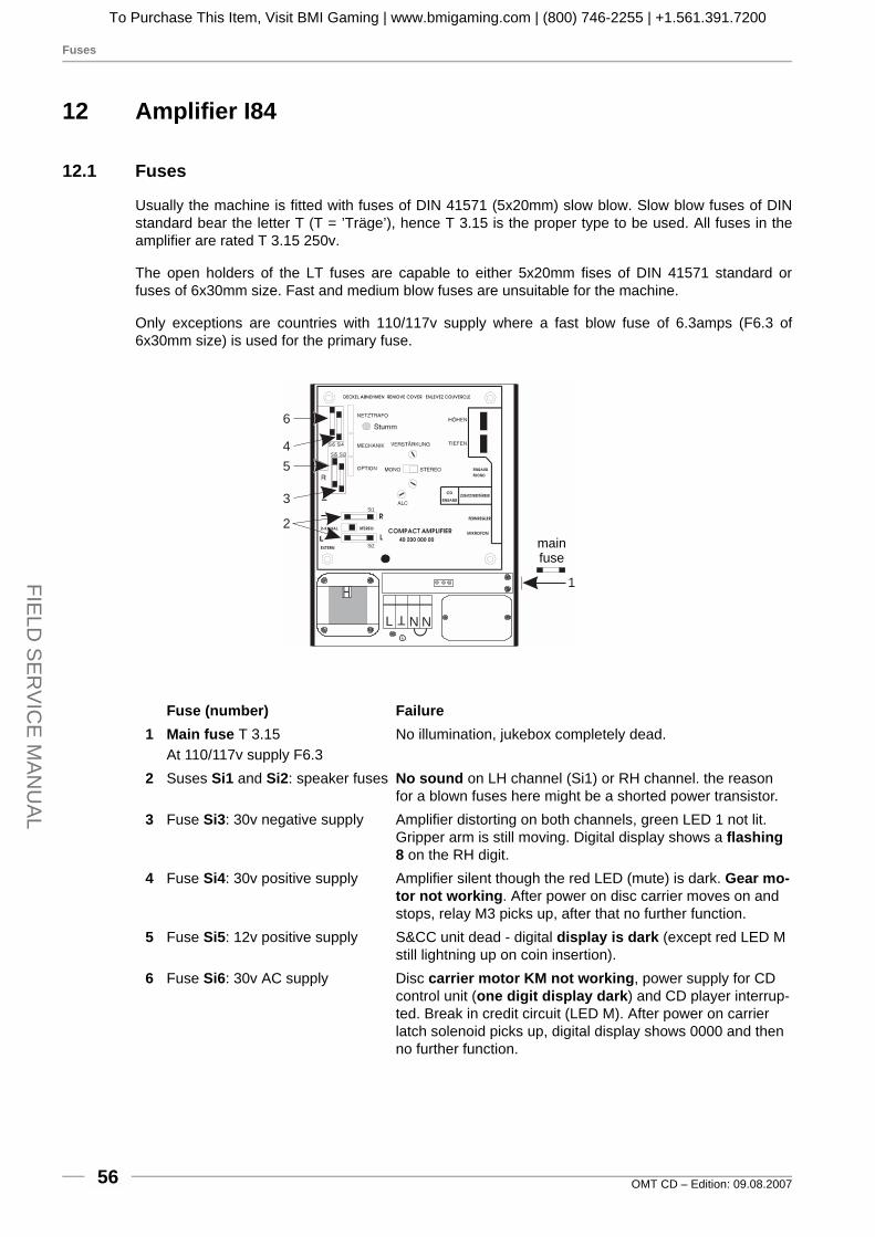
Fuses
OMT CD – Edition: 09.08.200756
FIELD
SE
RV
ICE
MAN
UA
L
12 Amplifier I84
12.1 Fuses
Usually the machine is fitted with fuses of DIN 41571 (5x20mm) slow blow. Slow blow fuses of DINstandard bear the letter T (T = ’Träge’), hence T 3.15 is the proper type to be used. All fuses in theamplifier are rated T 3.15 250v.
The open holders of the LT fuses are capable to either 5x20mm fises of DIN 41571 standard orfuses of 6x30mm size. Fast and medium blow fuses are unsuitable for the machine.
Only exceptions are countries with 110/117v supply where a fast blow fuse of 6.3amps (F6.3 of6x30mm size) is used for the primary fuse.
Fuse (number) Failure1 Main fuse T 3.15
At 110/117v supply F6.3No illumination, jukebox completely dead.
2 Suses Si1 and Si2: speaker fuses No sound on LH channel (Si1) or RH channel. the reason for a blown fuses here might be a shorted power transistor.
3 Fuse Si3: 30v negative supply Amplifier distorting on both channels, green LED 1 not lit. Gripper arm is still moving. Digital display shows a flashing 8 on the RH digit.
4 Fuse Si4: 30v positive supply Amplifier silent though the red LED (mute) is dark. Gear mo-tor not working. After power on disc carrier moves on and stops, relay M3 picks up, after that no further function.
5 Fuse Si5: 12v positive supply S&CC unit dead - digital display is dark (except red LED M still lightning up on coin insertion).
6 Fuse Si6: 30v AC supply Disc carrier motor KM not working, power supply for CD control unit (one digit display dark) and CD player interrup-ted. Break in credit circuit (LED M). After power on carrier latch solenoid picks up, digital display shows 0000 and then no further function.
H
L N NT
Si6
Si5
Si4
Si3
Si1
Si2
T
1
2
3
5
4
6
mainfuse
To Purchase This Item, Visit BMI Gaming | www.bmigaming.com | (800) 746-2255 | +1.561.391.7200

Volume control
OMT CD – Edition: 09.08.2007 57
FIE
LD S
ER
VIC
E M
AN
UA
L
12.2 Volume control
The control box, accessible from the rear side ofthe jukebox, is a separate unit and has two knobs(L and R). In „stereo mode“ (switch S in positionstereo) only the left knob is effective. In position „2Kanal“ (two channel) of the slide switch both chan-nels are controllable separately.
NOTE: The volume control unit can be screwed offand may be mounted at another place as a remotecontrol.
ATTENTION! Depending on the adjusted vo-lume of the jukebox noise levels of more than70 dB can be reached.
12.3 Automatic loudness controller
An internal automatic volume controller decreases the volume level of CDs recorded too loud to anoutput level defined by the ALC pot. So an equal volume level is reached. The ALC pot is pre-setfrom the factory. In left position of the adjustment pot the ALC does not operate.
12.4 Treble and bass control
The treble and the bass controls at the top RH-side of the amplifier may be set to any position to suitlocal acoustic requirements. The Mono-Stereo switch may also be set to either position, however, itmust be set to ‘Stereo’ if a stereophonic reproduction is desired.
12.5 Slide switch ’Stereo/2-Kanal’
In standard operating mode the slide switch„Stereo/2-Kanal“ is in position „Stereo“. In Position„2-Kanal“ the cabinet speakers of the jukebox areswitched to the left amplifier channel. Both socketsfor the external speakers L and R are switched tothe right amplifier channel.
If the slide switch of the volume control unit isswitched to „2-Kanal“ a separate control of bothcabinet speakers and external speakers (e.g. in an-other room) is possible (left knob for inside, rightone for outside). The slide switch „Mono-Stereo“has to be set to mode „Mono“.
Mono/Stereoslide switch
treble+ basscontrol
2-Channel/Stereoslide switch
AutomaticLoudness Control
To Purchase This Item, Visit BMI Gaming | www.bmigaming.com | (800) 746-2255 | +1.561.391.7200

Maximum amplifier load and external speakers
OMT CD – Edition: 09.08.200758
FIELD
SE
RV
ICE
MAN
UA
L
12.6 Maximum amplifier load and external speakers
The amplifier may not be loaded with more than 4ohms per channel (less ohms means more load!).If the amplifier is operating in 2-channel mode, the speakers are all loaded to the LH channel.The impedance of all external speakers per channel in Stereo mode should not be less than 8ohms,because the cabinet speakers represent a load of already 8ohms per channel.If the amplifier is working in 2-channel mode, the speakers are all loaded to the LH channel. The RHchannel (now switched to the sockets ’R-Extern’ and ’L-Extern’) now may be loaded with a minimumof 4ohms.
The output to a 4ohms load is 70watts sinus power at 1% distorsion, to 12ohms it is about 24watts,to 24ohms it is about 12watts. That means, that e.g. a 12ohms speaker connected to the externalchannel at Dual channel operation must be a type of at least 24watts, otherwise the speaker is indanger of destruction at higher volumes. Speaker groups, so-called HiFi boxes, may have, at certainfrequences, impedances much lower than their rating.
12.7 Connection of external speakers
Additional speakers may be connected via two speaker DIN plugs to the amplifier.
ATTENTION! In Stereo mode, do not connect a single speaker with less than 8ohms to the ampli-fier!
RR
R
LL
LL
2-Channel-2-Channel-
StereoStereo
slide switchslide switch
Remotecontrol
Remotecontrol
2K2K
2 channelStereo MonoStereo
R
DIN terminalLH-extern.
DIN Anschl.LH-extern.
DIN terminalRH-extern.
DIN terminalRH-extern.
6 Ohmload
internalspeakers
12 Ohminternalspeaker
12 Ohminternalspeaker
Amplifier switches in positions 2-CHANNEL and MONO
Remote control switched to 2-CHANNEL
Both amplifier switches in position STEREO
Remote control in position STEREO too
H
L N N
H
L N N
T T
T T
8Ω 8Ω 4Ω 4Ω
4Ω 4Ω
Connection of 2 speakers of 4ohmsin series representing a totalimpedance of 8ohms
To Purchase This Item, Visit BMI Gaming | www.bmigaming.com | (800) 746-2255 | +1.561.391.7200

Infrared remote control
OMT CD – Edition: 09.08.2007 59
FIE
LD S
ER
VIC
E M
AN
UA
L
12.8 Infrared remote control
If required an infrared remote control will be installedat the factory or can be delivered as a conversion kit(part no. 0050917; amplifier I84).
If it is already installed you will find the hand transmit-ter in the cashbox.
By pressing the buttons 'high' and 'low' at the sametime this hand transmitter can be re-programmed. It isthen set to work with jukeboxes which have an infraredremote control with selection buttons.
Batteries: 2 micro cells type LR03 (AAA) (will be deliv-ered).
The meanings of the buttons...
! HIGH! Increases the volume. Press the button rapidly
to increase the volume quickly.
! LOW! Decreases the volume. Press the button rapidly
to decrease the volume quickly.
! MUTE! As long as this button is pressed the jukebox is
muted.
! CANCEL! Cancels the playing track. If 'albumplay' is en-
abled the next track will be played.
NOTE: The infrared receiving unit memorizes the last volume value before switch off the jukeboxand starts with the same level when switched on again.
DW: 0050999
highervolumelower
volume mute
cancel
To Purchase This Item, Visit BMI Gaming | www.bmigaming.com | (800) 746-2255 | +1.561.391.7200
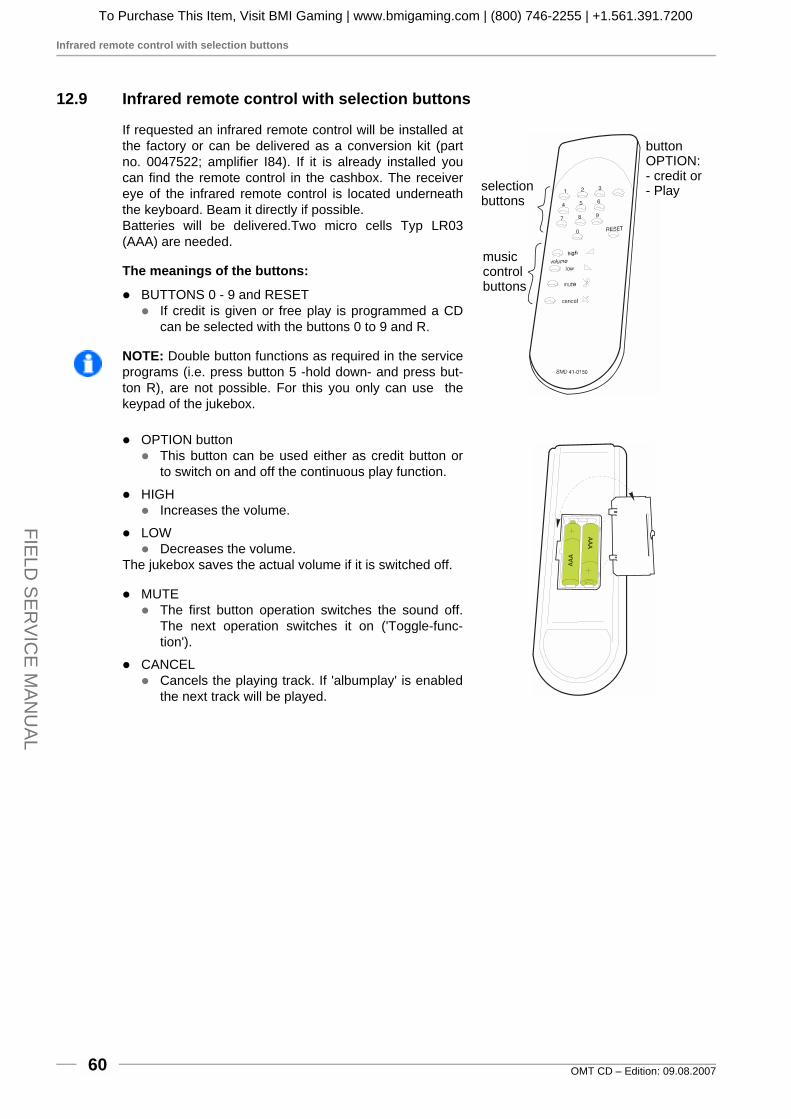
Infrared remote control with selection buttons
OMT CD – Edition: 09.08.200760
FIELD
SE
RV
ICE
MAN
UA
L
12.9 Infrared remote control with selection buttons
If requested an infrared remote control will be installed atthe factory or can be delivered as a conversion kit (partno. 0047522; amplifier I84). If it is already installed youcan find the remote control in the cashbox. The receivereye of the infrared remote control is located underneaththe keyboard. Beam it directly if possible.Batteries will be delivered.Two micro cells Typ LR03(AAA) are needed.
The meanings of the buttons:
! BUTTONS 0 - 9 and RESET! If credit is given or free play is programmed a CD
can be selected with the buttons 0 to 9 and R.
NOTE: Double button functions as required in the serviceprograms (i.e. press button 5 -hold down- and press but-ton R), are not possible. For this you only can use thekeypad of the jukebox.
! OPTION button! This button can be used either as credit button or
to switch on and off the continuous play function.
! HIGH! Increases the volume.
! LOW! Decreases the volume.
The jukebox saves the actual volume if it is switched off.
! MUTE! The first button operation switches the sound off.
The next operation switches it on ('Toggle-func-tion').
! CANCEL! Cancels the playing track. If 'albumplay' is enabled
the next track will be played.
selectionbuttons
musiccontrolbuttons
buttonOPTION:- credit or- Play
To Purchase This Item, Visit BMI Gaming | www.bmigaming.com | (800) 746-2255 | +1.561.391.7200
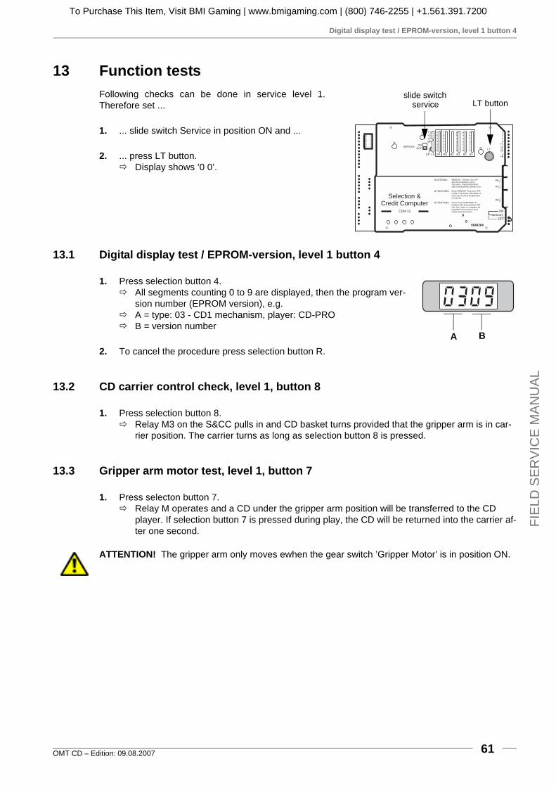
Digital display test / EPROM-version, level 1 button 4
OMT CD – Edition: 09.08.2007 61
FIE
LD S
ER
VIC
E M
AN
UA
L
13 Function testsFollowing checks can be done in service level 1.Therefore set ...
1. ... slide switch Service in position ON and ...
2. ... press LT button. # Display shows ’0 0’.
13.1 Digital display test / EPROM-version, level 1 button 4
1. Press selection button 4.# All segments counting 0 to 9 are displayed, then the program ver-
sion number (EPROM version), e.g.# A = type: 03 - CD1 mechanism, player: CD-PRO# B = version number
2. To cancel the procedure press selection button R.
13.2 CD carrier control check, level 1, button 8
1. Press selection button 8. # Relay M3 on the S&CC pulls in and CD basket turns provided that the gripper arm is in car-
rier position. The carrier turns as long as selection button 8 is pressed.
13.3 Gripper arm motor test, level 1, button 7
1. Press selecton button 7.# Relay M operates and a CD under the gripper arm position will be transferred to the CD
player. If selection button 7 is pressed during play, the CD will be returned into the carrier af-ter one second.
ATTENTION! The gripper arm only moves ewhen the gear switch ’Gripper Motor’ is in position ON.
LT buttonslide switch
service
MEMORY - Stecker von OFFauf ON umstecken, wennTop tunes, Popularitätszähleroder Kassenzähler arbeiten soll.
Move MEMORY Plug from OFFto ON if Top tunes, Pop Meter orCash Box Content Registrationis required.
Placer la prise MEMORY enposition ON, de la position OFFsi le Top Tunes, le compteur depopularité et la contenu de lacaisse sont demandés.
ACHTUNG:
ATTENTION:
ATTENTION:
Selection &Credit Computer
CDM 12 ON
OFFMemory
0040264
P8
P5
P6 16
15
18
GPGP + 6 BS B4 B3 B2 B1
F654320
7654320
6543210
6543210
6543210
ONOFF
SERVICE
Z
K
T.T.+2+3BR
1245
T11020
+B
T
M LT
A B
To Purchase This Item, Visit BMI Gaming | www.bmigaming.com | (800) 746-2255 | +1.561.391.7200
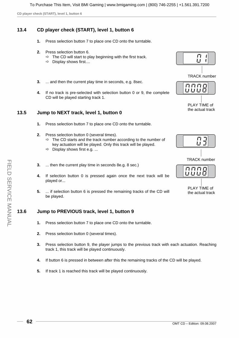
CD player check (START), level 1, button 6
OMT CD – Edition: 09.08.200762
FIELD
SE
RV
ICE
MAN
UA
L
13.4 CD player check (START), level 1, button 6
1. Press selection button 7 to place one CD onto the turntable.
2. Press selection button 6.# The CD will start to play beginning with the first track.# Display shows first....
3. ... and then the current play time in seconds, e.g. 8sec.
4. If no track is pre-selected with selection button 0 or 9, the completeCD will be played starting track 1.
13.5 Jump to NEXT track, level 1, button 0
1. Press selection button 7 to place one CD onto the turntable.
2. Press selection button 0 (several times).# The CD starts and the track number according to the number of
key actuation will be played. Only this track will be played.# Display shows first e.g. ...
3. ... then the current play time in seconds 8e.g. 8 sec.)
4. If selection button 0 is pressed again once the next track will beplayed or...
5. ... if selection button 6 is pressed the remaining tracks of the CD willbe played.
13.6 Jump to PREVIOUS track, level 1, button 9
1. Press selection button 7 to place one CD onto the turntable.
2. Press selection button 0 (several times).
3. Press selection button 9, the player jumps to the previous track with each actuation. Reachingtrack 1, this track will be played continuously.
4. If button 6 is pressed in between after this the remaining tracks of the CD will be played.
5. If track 1 is reached this track will be played continuously.
TRACK number
PLAY TIME ofthe actual track
TRACK number
PLAY TIME ofthe actual track
To Purchase This Item, Visit BMI Gaming | www.bmigaming.com | (800) 746-2255 | +1.561.391.7200

STOP playing, level 1, button 5
OMT CD – Edition: 09.08.2007 63
FIE
LD S
ER
VIC
E M
AN
UA
L
13.7 STOP playing, level 1, button 5
1. Press selection button 5.# CD play will be interrupted and display shows:
" To terminate all the tests to return to normal operation, set slideswitch Service to OFF and press LT button.
initial positionservice level 1mechanism type: CD1player type: CD-PRO
To Purchase This Item, Visit BMI Gaming | www.bmigaming.com | (800) 746-2255 | +1.561.391.7200
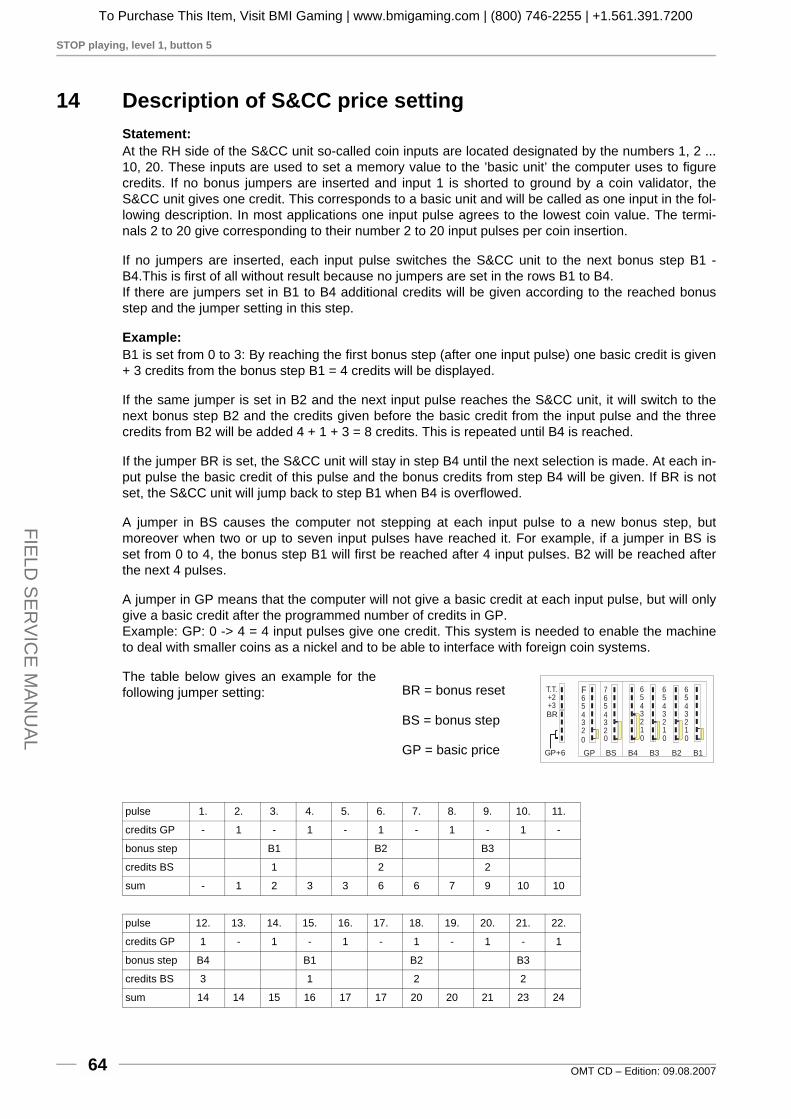
STOP playing, level 1, button 5
OMT CD – Edition: 09.08.200764
FIELD
SE
RV
ICE
MAN
UA
L
14 Description of S&CC price settingStatement:At the RH side of the S&CC unit so-called coin inputs are located designated by the numbers 1, 2 ...10, 20. These inputs are used to set a memory value to the ’basic unit’ the computer uses to figurecredits. If no bonus jumpers are inserted and input 1 is shorted to ground by a coin validator, theS&CC unit gives one credit. This corresponds to a basic unit and will be called as one input in the fol-lowing description. In most applications one input pulse agrees to the lowest coin value. The termi-nals 2 to 20 give corresponding to their number 2 to 20 input pulses per coin insertion.
If no jumpers are inserted, each input pulse switches the S&CC unit to the next bonus step B1 -B4.This is first of all without result because no jumpers are set in the rows B1 to B4.If there are jumpers set in B1 to B4 additional credits will be given according to the reached bonusstep and the jumper setting in this step.
Example:B1 is set from 0 to 3: By reaching the first bonus step (after one input pulse) one basic credit is given+ 3 credits from the bonus step B1 = 4 credits will be displayed.
If the same jumper is set in B2 and the next input pulse reaches the S&CC unit, it will switch to thenext bonus step B2 and the credits given before the basic credit from the input pulse and the threecredits from B2 will be added 4 + 1 + 3 = 8 credits. This is repeated until B4 is reached.
If the jumper BR is set, the S&CC unit will stay in step B4 until the next selection is made. At each in-put pulse the basic credit of this pulse and the bonus credits from step B4 will be given. If BR is notset, the S&CC unit will jump back to step B1 when B4 is overflowed.
A jumper in BS causes the computer not stepping at each input pulse to a new bonus step, butmoreover when two or up to seven input pulses have reached it. For example, if a jumper in BS isset from 0 to 4, the bonus step B1 will first be reached after 4 input pulses. B2 will be reached afterthe next 4 pulses.
A jumper in GP means that the computer will not give a basic credit at each input pulse, but will onlygive a basic credit after the programmed number of credits in GP.Example: GP: 0 -> 4 = 4 input pulses give one credit. This system is needed to enable the machineto deal with smaller coins as a nickel and to be able to interface with foreign coin systems.
The table below gives an example for thefollowing jumper setting:
pulse 1. 2. 3. 4. 5. 6. 7. 8. 9. 10. 11.
credits GP - 1 - 1 - 1 - 1 - 1 -
bonus step B1 B2 B3
credits BS 1 2 2
sum - 1 2 3 3 6 6 7 9 10 10
pulse 12. 13. 14. 15. 16. 17. 18. 19. 20. 21. 22.
credits GP 1 - 1 - 1 - 1 - 1 - 1
bonus step B4 B1 B2 B3
credits BS 3 1 2 2
sum 14 14 15 16 17 17 20 20 21 23 24
0 023456
23456
F
23456
10
23456
10
23456
10
7T.T.+2+3BR
GP BS B4 B3 B2 B1GP+6
BR = bonus reset
BS = bonus step
GP = basic price
To Purchase This Item, Visit BMI Gaming | www.bmigaming.com | (800) 746-2255 | +1.561.391.7200

Access to the player functions without S&CC unit
OMT CD – Edition: 09.08.2007 65
FIE
LD S
ER
VIC
E M
AN
UA
L
15 Integrated test program of the CD-PRO player
15.1 Access to the player functions without S&CC unit
For a test the complete player unit CD-PROcan be operated without S&CC unit.
The power supply from the installed ampli-fier, the sub-transformer and an amplifierwith CD input for the audio signal is required.
A one digit digital display indicates the cur-rent operation mode and three commandbuttons are located on the player chassis.
The one digit display is able to displaymore information.
To display two or more digits the infor-mation starts with a dark phase of ap-prox. 1 sec. followed by the digitsshown one after another with darkphase of 100 msec. between each digit.The most significant digit will be dis-played at first.
After power on and after a general resetcommand (display shows “8”), the pro-gram version number of the DeutscheWurlitzer GmbH CD control unit will bedisplayed with four digits followed bythe version number of the CD-PROservo processor with two digits.
If the player is in stand by and the threebuttons on the player are pressed at thesame time the above mentioned se-quence will be displayed but withoutshowing “8” for “reset active”.
CA
UTIO
N
one figuredisplay
button 1 (mode)
button 2
button 3
100ms pause
mode = 0
time
moment of power ON
reset active
programversion numberWurlitzer CD control unit01.20
display dark for 1 sec
date of release08.05.
CD-PRO versionnumber 3.7
To Purchase This Item, Visit BMI Gaming | www.bmigaming.com | (800) 746-2255 | +1.561.391.7200

Test functions CD-PRO
OMT CD – Edition: 09.08.200766
FIELD
SE
RV
ICE
MAN
UA
L
15.2 Test functions CD-PRO
If “repeat CD” had been selected with thebuttons 2 + 3 in mode 0 the display will be“99”. At each beginning of a new track it willbe displayed with two digits.
If “repeat track” had been selected with thebuttons 2 + 3 in mode 1 the actual playedtrack will be displayed.
By pressing of two buttons at the same timeadditional values will be displayed:
! Buttons 1+2: ! The last occurred error code will be
displayed (ref. to error code table).This error code will be reset after thisretrieval or after a CD-PRO reset (e.g.the next power on).
! Buttons 1+3: ! The actual playing track will be dis-
played.
! Buttons 1+2+3:! No CD is playing: Program version
and date of release.! CD is playing: Max. / min. track number will be displayed.
NOTE: If commands will be sent to the CD-PRO player, the display will flash. During this time nocommands given by the buttons will be accepted. While the table of contents (TOC) is read an 8 flas-hes in the display. In this way, the necessary time to read the TOC can be prolonged. So bad CDscan be recognised and taken out.
mode dis-play
button 1(mode)
button 2 button 3 buttons 2 + 3 together
0 mode 1 start stop repeat CD
1 mode 2 next track previous track repeat track
2 mode 3 search forward search backward single, double speed
3 mode 4 pause ON pause OFF
4 mode 5 volume + volume - mute
5 mode 0 track + 1 track - 1 play selected track (read TOC, if necessary)
CA
UTIO
N
Taste 1 (mode)
Taste 2
Taste 3
mode display
Error code
0
2
7
8
10
12
13
31
32
33
34
40
41
42
43
44
45
48
Meaning
No error
Focus error or no disc
Subcode error, no valid subcode
TOC error
Radial error
Fatal sledge error
Turntable motor error
Search time out
Search binary error
Search index error
Search time error
Illegal command
Illegal value
Illegal time value
Communication error
Reserved
HF detector error
Emergency stop
To Purchase This Item, Visit BMI Gaming | www.bmigaming.com | (800) 746-2255 | +1.561.391.7200

Special test functions of the CD-PRO player
OMT CD – Edition: 09.08.2007 67
FIE
LD S
ER
VIC
E M
AN
UA
L
15.3 Special test functions of the CD-PRO player
Service program of CD-PRO (mode 9). With this service program different functions of the CD-PROplayer can be tested.
How to call:Switch main power OFF. Press button 1 - holddown - and switch main power on. (Remark:“Power ON - OFF” can also be done by discon-necting the wire bk./gy. from pin 6 of the subtransformer.)
Function:The CD control unit steps into mode 9 and runsthe tests 90 up to 99. Mode 9 will be displayedcontinuously. While changing the test step it willbe displayed with two digits
Remarks:For starting test step 94 a CD has to be placedon turntable.
! The button 1...has no function during this test.
! The button 2...switches to the next test step.
! The button 3...switches to the previous test step.
Quit:Press button 2 while test 98 is running. Controlunit steps over test 99 to mode 0 automatically.
Test 91: You can check the laserlight with an in-frared indicator.
Test 93: Without a CD: laser lense moves upand down. If you put a CD on the turntable whilethe test runs the lens stops moving if it finds thefocus point.
Test 95: The turntable motor must spin.
Test 98: The sledge moves itself from inside to outside and back again. If this test is successful thespeed of the disc must change to lower speed at the outside of the disc.
Laser light OFF
Laser light ON
Focus OFF
Search focus
Turntable motor OFF
Turntable motor ON
Radial Servo OFF
Radial Servo ON
Sledge moves forwardand backward.
Quit service program,back to mode 0.
Start service program
Pre
ss
button
2to
reach
nextste
p.
Pre
ss
button
3to
reach
pre
vio
us
ste
p.
90
91
92
93
94
95
96
97
98
99 Mode0
next test step
previous test step
To Purchase This Item, Visit BMI Gaming | www.bmigaming.com | (800) 746-2255 | +1.561.391.7200
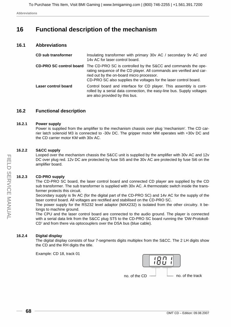
Abbreviations
OMT CD – Edition: 09.08.200768
FIELD
SE
RV
ICE
MAN
UA
L
16 Functional description of the mechanism
16.1 Abbreviations
16.2 Functional description
16.2.1 Power supplyPower is supplied from the amplifier to the mechanism chassis over plug ’mechanism’. The CD car-rier latch solenoid M3 is connected to -30v DC. The gripper motor MM operates with +30v DC andthe CD carrier motor KM with 30v AC.
16.2.2 S&CC supplyLooped over the mechanism chassis the S&CC unit is supplied by the amplifier with 30v AC and 12vDC over plug red. 12v DC are protected by fuse Si5 and the 30v AC are protected by fuse Si6 on theamplifier board.
16.2.3 CD-PRO supplyThe CD-PRO SC board, the laser control board and connected CD player are supplied by the CDsub transformer. The sub transformer is supplied with 30v AC. A thermostatic switch inside the trans-former protects this circuit. Secondary supply is 9v AC (for the digital part of the CD-PRO SC) and 14v AC for the supply of thelaser control board. All voltages are rectified and stabilised on the CD-PRO SC. The power supply for the RS232 level adaptor (MAX232) is isolated from the other circuitry. It be-longs to machine ground. The CPU and the laser control board are connected to the audio ground. The player is connectedwith a serial data link from the S&CC plug ST5 to the CD-PRO SC board running the ’DW-Protokoll-CD’ and from there via optocouplers over the DSA bus (blue cable).
16.2.4 Digital displayThe digital display consists of four 7-segments digits multiplex from the S&CC. The 2 LH digits showthe CD and the RH digits the title.
Example: CD 18, track 01
CD sub transformer Insulating transformer with primary 30v AC / secondary 9v AC and14v AC for laser control board.
CD-PRO SC control board The CD-PRO SC is controlled by the S&CC and commands the ope-rating sequence of the CD player. All commands are verified and car-ried out by the on-board micro processor.CD-PRO SC also supplies the voltages for the laser control board.
Laser control board Control board and interface for CD player. This assembly is cont-rolled by a serial data connection, the easy-line bus. Supply voltagesare also provided by this bus.
no. of the CD no. of the track
To Purchase This Item, Visit BMI Gaming | www.bmigaming.com | (800) 746-2255 | +1.561.391.7200

Functional description
OMT CD – Edition: 09.08.2007 69
FIE
LD S
ER
VIC
E M
AN
UA
L
16.2.5 Number of plays and cash counterThe S&CC unit acknowledges coin insertion by indicating the number of selectable plays and a se-ries of relay pulses (relay C). The plays are established depending on the setting of the bonus jump-ers in the row s B1 to B4 on the S&CC. A mechanical counter connected to plug green pin 3(connects to ground) and +30v registers the coins inserted in basic units. The mechanical counter isoptional.
16.2.6 Selection and CD carrierAfter a valid selection the S&CC operates the M3 relay, connecting plug blue pin 4 to ground. CDcarrier latch solenoid M3 pulls in and starts carrier motor KM by microswitch m3. The CD carrierturns to the selected position.
16.2.7 Start / counting processThe CD carrier is provided with tooth slots at each CD compartment. By means of a light gate in frontof the carrier the exact slot position is controlled. The tooth slots of each compartment are registeredby the S&CC and visible by the flashing Z-LED when the carrier rotates. Just before passing the 01position the K-LED will flash indicating CD 1. Slot 01 is found by passing of a special bracketmounted underneath the carrier base plate. The teeth (Z-LED) are counted after the K pulse hasbeen sent.
16.2.8 CD transferIf the desired CD has reached the gripper arm position, M3 is de-energized and the CD carrier stops.To transfer the CD the S&CC starts the gripper arm motor MM over plug blue pin 2 from relay M. Atthe same time a ’Reset’ command is transferred to the CD control unit which resets the CD-PRO SCcontrol board and laser control board. The gripper arm now transfers the CD to the player. The relayM is active for 1.5seconds. During this time the gear motor has turned and K6 (slide contact on thegear box contact disc) switches the motor into self holding position. After the CD is placed onto theturntable and held by the magnetic clamp arm, K1 opens, ground is disconnected from the gear mo-tor MM and it stops. K6 is closed.
16.2.9 Mute offThe amplifier is now activated from the open K1 contact by the mute or cancel line grey over plugmechanism. D1 prevents continuous mute from the S&CC.
16.2.10 PlayDuring the 6 seconds lasting transfer operation the S&CC sends the selection information to the CD-PRO SC which is carried out by the laser control board. The CD starts after approx. 2 seconds. Theaudio frequency signal is connected with RCA jacks to the amplifier CD-input.At the end of the track the CD control is switched to pause mode. This is transferred over the com-munication line to the S&CC which recognises this condition which then causes a stop-title-com-mand. The CD stops.
16.2.11 Cancel3 seconds after the start of a play a track can be interrupted with the cancel button.The S&CC recognises this over plug green/pin 1. Diode 2 in the mechanism chassis prevents restartof the gripper motor by pulling the input to ground. Otherwise the gripper mechanism would pull theCD from the still spinning player. The control immediately sends a stop command through the ’DW-Protokoll-CD’ to the CD-PRO SC for stopping the CD. A serial acknowledgement informs the S&CC.
To Purchase This Item, Visit BMI Gaming | www.bmigaming.com | (800) 746-2255 | +1.561.391.7200

Functional description
OMT CD – Edition: 09.08.200770
FIELD
SE
RV
ICE
MAN
UA
L
16.2.12 CD returnThe mechanism MM is being activated from the S&CC for 1.5 seconds. The gear box contact discbrings K6 into self-latching (K1 is closed = ground). When K6 reaches the insulated gap the grippermotor MM stops. The gripper arm has returned the CD. K7 and K8 are closed again. The closed K7reports over the circuit around M3 (-30v DC over wire grey plug blue/pin 4 (relay M3 open) to T22 inthe S&CC): ’CD in carrier’. The closed K8 allows a new CD search.
16.2.13 New selectionIf another selection has been registered in the S&CC the sequence is repeated from the beginning.
17 Error messages and remedy
Error Possible reason and remedy! No operation, lamps and dis-
play are dark.! Powerline interrupted.! Power switch is in OFF position.! Check main fuse (3.15/6A) at the amplifier.
! No operation, only the display is dark.
! Amplifier K99: check fuse F4 ! Amplifier F91: check fuses Si 102 and Si 103! Amplifier I84: check fuse Si5! Check transformer plug from amplifier to the S&CC
! Coins are badly or not accep-ted.
! Jammed coins in the validator.! Coin acceptor needs to be cleaned.! Return lever mechanism jammed.
! Coins are accepted but no cre-dit (plays) on display.
! Check plugs at RH side of the SCC unit.! Check if the slide switch on the SCC unit is in position service
OFF.! Display is flashing after a se-
lection.! Not enough money inserted.! Number of CDs in the magazine is programmed incorrectly
(see chapt. 2.3, on page 9)! Amplifier K99: check fuse F1! Amplifier F91: check fuse Si 101! Amplifier I84: check fuse Si6
! After a selection the carrier turns and stops.
! Set the switch ‘gripper arm’ on the chassis to ON position.
! After a selection the carrier turns constantly.
! Faulty lamp in the carrier light gate.! Plug ‘Black’ at the SCC unit in reverse position.
! Some CDs are not playing. ! CDs in the magazine are in reverse position.! CDs need to be cleaned.
! No sound. ! Amplifier K99: turn volume control at the rear side of the jukebox clockwise. Check fuses F2 and F3
! Amplifier F91: press button ‘+’ at the rear side of the jukebox! Amplifier I84: turn volume control at the rear side of the
jukebox clockwise. Check fuses Si1 and Si2! Check the loudspeaker plugs at the amplifier.! Check the cable from the CD player to the amplifier.
! Sound from one channel only. ! K99 amplifier: set the silde switch on the volume remote cont-rol in position stereo
To Purchase This Item, Visit BMI Gaming | www.bmigaming.com | (800) 746-2255 | +1.561.391.7200

Failures with illumination, display and power system generally
OMT CD – Edition: 09.08.2007 71
FIE
LD S
ER
VIC
E M
AN
UA
L
17.1 Failures with illumination, display and power system generally
Symptom Cause Possible faults! No light, jukebox not
working at all! No power at wall so-
cket; open primary cir-cuit
! Wall socket defective. Main fuse blown! Mains fuse of the amplifier blown! Internal break in line cord or plug! Line switch off or defective
! Illumination does not light, but jukebox works
! Defective lamp circuit ! Lamp circuit plug not in light socket at amplifier! Lamp not properly seated in holder! Defective starter, defective lamp
! Bubble tubes do not work
! Colour tubes do not rotate
! Lamp 24v does not light
! Defective 24v circuit ! Power supply leading from transformer to dis-tribution interface interrupted
! Fuses on interface (1A/M) defective! CAUTION! Short circuit in harness of heating
resistors possible
! Digital display remains dark, but jukebox works
! Signal supply leading to display interrupted
! 14pole D.I.L. plug not set or wrong way round (correct: flat cable is coming from LH side, orange below)
! Digital display shows nonsense figures, but jukebox works
! Signal lines interchan-ged
! 14pole D.I.L. plug displaced (not in line with the base)
! Computer defective, e.g. IC7! Digital display shows
incomplete figures (missing segments)
! The fault is the same with all four digits
! Signal for one (or some) segments mis-sing
! One pin (or some) of 14pole plug broken off! One wire (or some) of flat cable broken! Broken connection at display PC-board! Computer defective, e.g. IC7
! Digital display shows incomplete figures (missing segments)
! The fault, however, occurs with one (or up to three) of the four di-gits only
! Segment signal does not reach this digit
! Cracked connection on display PC-board! Defective display unit (4 identical one-digit
units)
! One of the digits of display completely off
! Multiplex signal mis-sing
! Defective D.I.L. plug or broken wire (A1, A2, A3, A4)
! Display or computer defective (T23 - T26)
To Purchase This Item, Visit BMI Gaming | www.bmigaming.com | (800) 746-2255 | +1.561.391.7200

Faults with the coin system
OMT CD – Edition: 09.08.200772
FIELD
SE
RV
ICE
MAN
UA
L
17.2 Faults with the coin system
The jukebox, however, operates normally with free credit established with the jumper in therow GP at the S&CC unit (0 - F)
The function of the coin system can be checked by observing the LED M on the computer, whichshould light up with every coin accepted. Credits can also be given with the credit button on the inter-face of the electronic coin acceptor (ECA). If a mechanical coin acceptor is installed, then with thecredit button next to the coin acceptor.
Symptom Cause Possible faults! Coins rejected ! Disabled coin acceptor
! No power supply (ECA)
! Dirt, oil or dust particle in the coin acceptor! coin acceptor maladjusted! Reject lever jammed holding the coin acceptor
open! Coin acceptor or entire jukebox not leveled! Interruption in harness from S&CC unit over
coin acceptor interface to ECA! Interface defective
! Single coins give wrong credits (or none at all)
! Coin actuates the wrong coin switch
! Coin pulse does not reach the computer
! ECA defective
! Coin acceptor not properly positioned, leads the coin to an improper switch paddle or by passing it
! One line of the coin switches to computer ca-ble broken, disconnected at either end or wron-gly set at computer connector
! For ECA: switching transistor at the interface defective
! Permanent credit! Display shows perma-
nently ’1’! Credit free selections
! Jumper is set from 0 to F in row GP (free play)
!
! Wrong credits, repeti-tive or all the time, with credits higher or lower than program-med pricing
! Programming mistake ! Jumper BR is not set, then reset to bonus level 1 (B1) if bonus level 4 is overstepped
! Unintentional programming in happyHour pro-gramming level
! Programming jumper making poor contact(Note: modifications in reposition of jumpers are only effective by switch off or pressing the LT button)
! No credit, coins are properly accepted
! Free play, with GP-jumper 0 - F still pos-sible
! All coin input lines dsi-abled
! Credit inputs inactive (LED M does not light up)
! Checking of single in-puts (1, 2, 4, 5, T1, 10, 20) with a ground con-nected test wire
! 30v AC does not reach the computer (from am-plifier to CD mechanism to plug red/pin 1 at the S&CC)
! Computer defective (D7, LED M)
! No credit although coins are registered (LED M lights up)
! Even no free play cre-dit with GP jumper set from 0 to F
! Computer out of ope-ration
! No 12v power supplied to the computer (pin 2 and 4 plug red)
! Computer defective
To Purchase This Item, Visit BMI Gaming | www.bmigaming.com | (800) 746-2255 | +1.561.391.7200

Faults by selection entry
OMT CD – Edition: 09.08.2007 73
FIE
LD S
ER
VIC
E M
AN
UA
L
17.3 Faults by selection entry
(Credit system does work)
! No credit, LED M is lit permanently
! Permanent contact to ground of one or more coin inputs
! Ground connection of several coin input leads (check by disconnecting the leads at the S&CC coin inputs)
! Defective transistor at the ECA interface (if existing)
! Partially defective transistor may cause free credit
! Function check with ground connections to se-veral coin inputs of the S&CC
Symptom Cause Possible faults! No selections! Selection is displayed
flashingly
! Selection is not accep-ted
! No credit available (CAUTION! After free play setting LT button has to be pressed)
! The entered selection is higher than the pro-grammed number of CDs
! The selected CD is programmed for BGM only! The selected CD is disabled
! No selections! Numbers of actuated
keys not displayed (only credit is shown)
! Open circuits in the keyboard wiring
! Plug yellow displaced or not inserted deep enough
! Key Reset permanently closed or shorted to ground (pole 12, brown, plug yellow)
! Computer defective! No selections! In standby the LH digit
of display shows a number, but selection keys are disabled
! With insertion of further coins the new credit is displayed pro-perly
! Permanent selection signal from that key which the number is displayed
! Jammed key, permanently closed key contact! Wire of this contact is shorted to ground! Computer defective (C60 - C70, D44 - D66
possibility of ground shorting, IC8, IC9)! Check with digital multimeter: plug yellow pin2
to 12 approx. 5v DC! Function check with test wire to ground
! No response from one key
! Open circuit with this key
! Malfunction of key contact! Insufficient key travel! Broken wire on this key! Plug yellow not seated good enough! Computer defective with an affected input cir-
cuit (R65 to 86, D45 to 65, IC8, IC9)! The CD played is not
the one selected! The selection was
properly displayed
! Improper counting of CD carrier position
! Wrong adjustment of light control gates! Illumination light affecting Z light gate, reflec-
tions at the adges of carrier base plate! Record carrier latch delayed by mechanical
friction or too wide opening (latching too late)! Light control gate retarded
! After power on one track or more are played without selec-tion
! There are selections left in the memory
! Credit and selection reset after power off not used
To Purchase This Item, Visit BMI Gaming | www.bmigaming.com | (800) 746-2255 | +1.561.391.7200

Faults by selection entry
OMT CD – Edition: 09.08.200774
FIELD
SE
RV
ICE
MAN
UA
L
! The CD played is the one selected, howe-ver, not the selected track
! Selection does not cor-respond to the label
! Laser control board defective
! The selected track number is higher then the number of tracks on CD.
! After reaching the highest track number, the la-ser control board starts to count from the be-ginning again
! The selected CD is not played
! The CD carrier is rota-ting permanently
! Counting pulse Z or sensing pulse K mis-sing
! lamp of light agte dark! Break in harness to plug BLACK! S&CC defective (IC10, C75 - C78, D92, D94)
! Digital display shows the selection correctly, but after this the juke-box does not operate
! The S&CC gets the impression that a CD is still playing
! Caused by a defective or maladjusted K7 switch the voltage 30v DC at pin 4 plug GREY is missing
! This voltage usually indicates the replacing of a CD in carrier after playing
! If this circuit is interrupted the status of S&CC is the same as CD is playing, so it is not able to start the carrier for a new search
! S&CC defective (T22)! (Program version 3.09 does not take back a
CD after a fault occurs)! The selected CD is
placed onto the turn-table, but will not be played
! The digit on the CD control does not light
! After approx. 50 se-conds CD will be re-turned to carrier
! 30v AC supply for CD control and player mis-sing
! Fuse blown! Interrupts in lines from amplifier to S&CC or
from there to CD controller! Sub transformer switched off by its thermo-
static switch! Sub transformer defective! Voltage control ICs on CD-PRO SC faulty
! The selected CD is placed onto the turn-table, but will not be played
! The digit on the CD control shows ’0’
! After approx. 50 se-conds CD will be re-turned to carrier
! Communication bet-ween S&CC P5 and CD control interrupted
! Data leads between S&CC and CD controller interrupted
! (In this case operation is possible in mode 0 button T2, stop with T3)
! The selected CD is placed onto the turn-table, but will not be played, but after ap-prox. 50 seconds CD will be returned to car-rier
! Failure between DW-CD control and laser control board or laser control board and player
! Leads not deep enough inserted between player, laser control board or DW-CD control
! Player or laser control board defective
To Purchase This Item, Visit BMI Gaming | www.bmigaming.com | (800) 746-2255 | +1.561.391.7200

Repetitive apply of selected or non-selected CDs to turntable
OMT CD – Edition: 09.08.2007 75
FIE
LD S
ER
VIC
E M
AN
UA
L
17.4 Repetitive apply of selected or non-selected CDs to turntable
17.5 Failures in the system carrier - gripper arm
Symptom Cause Possible faults! Permanent gripper
arm movement (with or without CD) with the CD carrier not tur-ning in between
! This continues even if plug BLUE is discon-nected at the S&CC
! Main cam motor MM not stopping at the end of the play cycle
! Wiper switch K6 maladjusted
! Permanently gripper arm movement
! Discontinued after plug BLUE is pulled off at the S&CC
! Computer running out of program
! Computer out of program routine (cut power to S&CC for a second to initiate a restart of pro-gram)
! Computer defective (relay 2, T2 or T22)! Microswitch K7 or carrier latch solenoid M3 de-
fective
Symptom Cause Possible faults! Record carrier perma-
nently rotating, even after plug BLUE is pulled off
! If a selection is made the gripper arm ran-domly takes a CD onto the turntable
! Carrier latch perma-nently open
! Carrier latch or its solenoid jammed
! Record carrier perma-nently rotating
! Sometimes the grip-per arm randomly takes a CD onto the turntable, but the CD will not be played
! Also by pressing LT button the gripper arm takes a CD onto the turntable, the CD will not be played
! After power off for a short time a flashing 8 will appear in addition on the display
! Carrier latch solenoid permanently switched on
! Grey line from M3 to pole 4 of plug BLUE shor-ted to ground
! S&CC defective (relay 4 sticks, T4 defective)
To Purchase This Item, Visit BMI Gaming | www.bmigaming.com | (800) 746-2255 | +1.561.391.7200
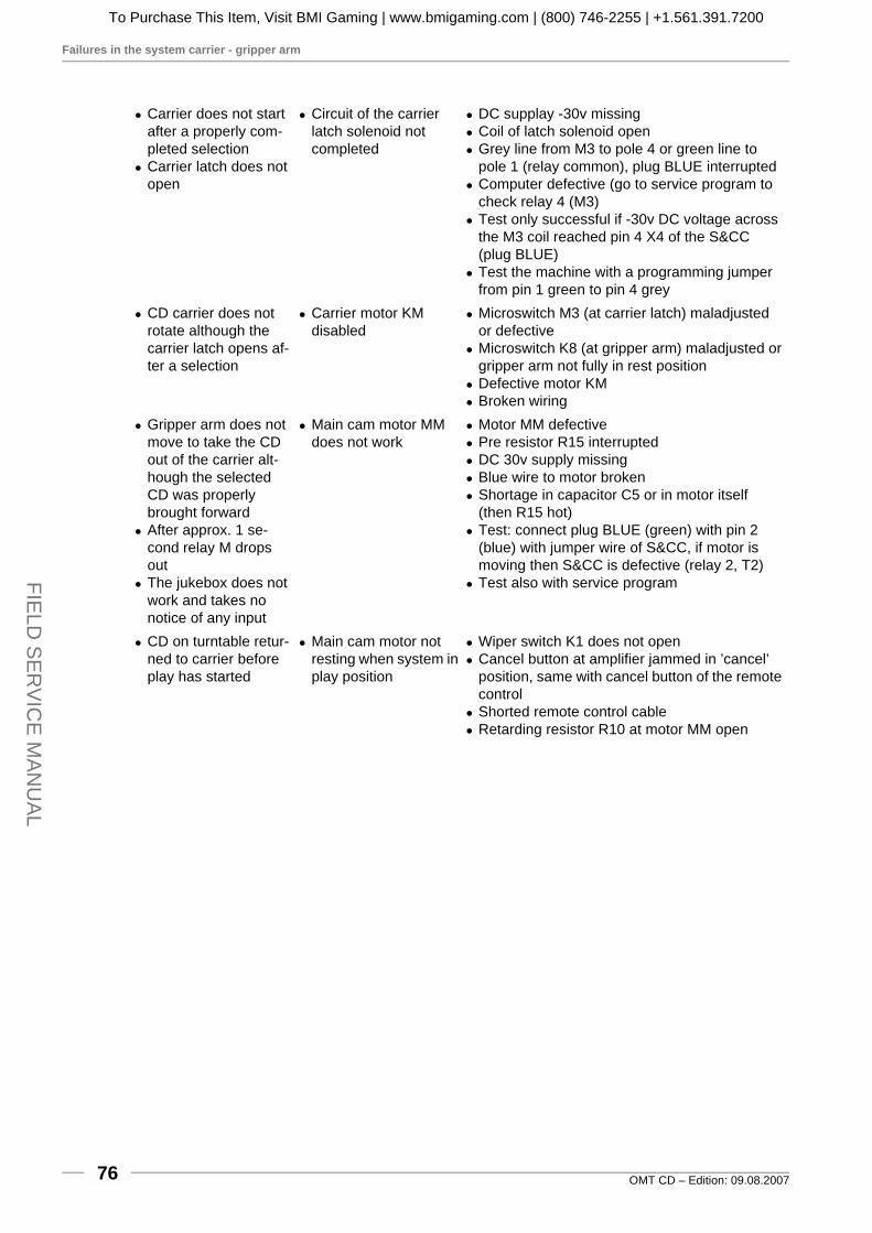
Failures in the system carrier - gripper arm
OMT CD – Edition: 09.08.200776
FIELD
SE
RV
ICE
MAN
UA
L
! Carrier does not start after a properly com-pleted selection
! Carrier latch does not open
! Circuit of the carrier latch solenoid not completed
! DC supplay -30v missing! Coil of latch solenoid open! Grey line from M3 to pole 4 or green line to
pole 1 (relay common), plug BLUE interrupted! Computer defective (go to service program to
check relay 4 (M3)! Test only successful if -30v DC voltage across
the M3 coil reached pin 4 X4 of the S&CC (plug BLUE)
! Test the machine with a programming jumper from pin 1 green to pin 4 grey
! CD carrier does not rotate although the carrier latch opens af-ter a selection
! Carrier motor KM disabled
! Microswitch M3 (at carrier latch) maladjusted or defective
! Microswitch K8 (at gripper arm) maladjusted or gripper arm not fully in rest position
! Defective motor KM! Broken wiring
! Gripper arm does not move to take the CD out of the carrier alt-hough the selected CD was properly brought forward
! After approx. 1 se-cond relay M drops out
! The jukebox does not work and takes no notice of any input
! Main cam motor MM does not work
! Motor MM defective! Pre resistor R15 interrupted! DC 30v supply missing! Blue wire to motor broken! Shortage in capacitor C5 or in motor itself
(then R15 hot)! Test: connect plug BLUE (green) with pin 2
(blue) with jumper wire of S&CC, if motor is moving then S&CC is defective (relay 2, T2)
! Test also with service program
! CD on turntable retur-ned to carrier before play has started
! Main cam motor not resting when system in play position
! Wiper switch K1 does not open! Cancel button at amplifier jammed in ’cancel’
position, same with cancel button of the remote control
! Shorted remote control cable! Retarding resistor R10 at motor MM open
To Purchase This Item, Visit BMI Gaming | www.bmigaming.com | (800) 746-2255 | +1.561.391.7200

Failures with sound reproduction
OMT CD – Edition: 09.08.2007 77
FIE
LD S
ER
VIC
E M
AN
UA
L
17.6 Failures with sound reproduction
17.7 CD not properly returned to carrier
Symptom Cause Possible faults! Clicks and banging
noises during CD playing
! Jump over of traces
! Reading of CD data disturbed
! CD defective (error correction for insignificant defects only)
! Dirty optic caused by nicotine and/or dust par-ticle
! Maladjusted optic assembly! Faults in CD player or laser control board
! CD moves but no sound
! Faults in the system of CD controller - ampli-fier - speaker
! Audio frequency cable at CD controller or amp-lifier (chinch socket) not inserted
! Audio cable is inserted in the Phono input of amplifier, not in CD input
! Speaker fuses blown! Wire grey (pin 8) amplifier to mechanic shorted
to ground! Amplifier defective! Laser control board defective
! Hum in sound repro-duction
! Ground loop! Amplifier or CD cont-
roller defective
! Gripper arm touches the chassis of the player in play position
! Other connections between player ground and chassis ground
! Ground loop out of the jukebox caused by ad-ditional equipment
! Amplifier or CD controller defective
Symptom Cause Possible faults! Gripper arm does not
move to return the CD into the carrier
! Main cam motor does not start
! Error at motor MM could have developed while a CD was playing
! Returned CD not pro-perly unclamped (not freed) in the carrier
! Main cam motor swit-ched off too early
! Wiper switch K6 wrongly adjusted
! CD missing in com-partment is found in other compartment or somewhere about the chassis
! Gripper arm generally moving too fast (time for one complete cam rotation is 11 to 13 se-conds)
! Disadjustment of gripper arm! Gripper arm sticks to the centering disc (CD
holder arm)! Wrong adjustment of puck arm height! Cam motor too fast
To Purchase This Item, Visit BMI Gaming | www.bmigaming.com | (800) 746-2255 | +1.561.391.7200

Microfone kit (part no. 0006953)
OMT CD – Edition: 09.08.200778
FIELD
SE
RV
ICE
MAN
UA
L
18 Accessories
18.1 Microfone kit (part no. 0006953)
This unit enables the use of the jukebox as a pagingsystem, when playing as well as during idling periods.If the paging microphone is switched on while thejukebox is playing, the music will be muted for this pe-riod. This kit is to be connected at the microphonesocket of the amplifier. The length of the cable be-tween mike pre-amp and the jukebox is approx. 45 ft /15 m.
18.2 BGM-Connector
This equipment offers two features:
1. The sound of an external source (300mV - 1V),e.g. radio or tape, will be reproduced over thespeakers of the jukebox with adjustable volume.A selection over the jukebox will mute this source,and it returns only after all selections have beenplayed. (Time-lag can be adjusted).
2. Connecting the jukebox to an existing back-ground system (amplifier), the sound of thisequipment is switched off as long as the jukeboxis playing. The hook-up for this adapter is thesame as the microphone.
BGM connector kit part no.:Amplifier K99 and F91: 0048130Amplifier I84: 0035579
Extern.Amplif.
F91Amplif.
Ext.
Ampl
Ext.
Tape
Ext.
Tape
L
R
R
R
RL
L
L
CDPlayerCD
Player
F91 Amp.Aux.
0048133
F91Ampl.Micro
Music/BGMConnector
+7,5V
-7,5V Time
To Purchase This Item, Visit BMI Gaming | www.bmigaming.com | (800) 746-2255 | +1.561.391.7200

OMT CD – Edition: 09.08.2007 79
19 Wiring and connection diagrams
NOTE: Upon request you can also have wiring and connection diagrams in DIN A3 size. Therefore pleasecontact the service department of Deutsche Wurlitzer GmbH. We will send them to you either by mail ore-mail (.pdf format).
19.1 Wiring diagram door - illumination
S = Starter für EinzelschaltungS1 = Starter für Serienschaltung
S = Starter for single lamp
S1 = Starter for 2 lamps series-connected
KlemmenleisteTerminal block
1 2 3 4
Vorschalt-Gerät 220 V50 oder 60 Hz
Ballast 220 V50 oder 60 Hz
30W
40W
15W
NPeL
Sw SwBr
Br
Bl
Bl
Bl Bl
Br
Br
Bl Br
18
/20
W
S1
S1
18
/20
W
S1
15W
15W
S1
S
15 WBl
Br
Schaltplan Tür - BeleuchtungWiring diagram door - illumination
4501-rs
To Purchase This Item, Visit BMI Gaming | www.bmigaming.com | (800) 746-2255 | +1.561.391.7200

OMT CD – Edition: 09.08.200780
19.2 Connection diagram OMT CD
Tie
fton
-L
au
tsp
rech
er
Ba
ss
Sp
ea
ke
r0
011
78
4
An
sch
lussp
lan
On
eM
ore
Tim
em
itC
D-P
RO
Sp
iele
ru
nd
Ve
rstä
rke
rK
99
On
eM
ore
Tim
eco
nn
ectio
nd
iag
ram
with
CD
-PR
Op
laye
ra
nd
am
plifie
rK
99
47
02
HE
L-rs
COMPONENTCOMPONENTCOMPONENTCOMPONENTCOMPONENTCOMPONENTCOMPONENTCOMPONENTCOMPONENTCOMPONENTCOMPONENTCOMPONENTCOMPONENTCOMPONENTCOMPONENTCOMPONENTCOMPONENTCOMPONENTCOMPONENTCOMPONENTCOMPONENTCOMPONENTCOMPONENTCOMPONENTCOMPONENTCOMPONENTCOMPONENTCOMPONENTCOMPONENTCOMPONENTCOMPONENTCOMPONENTCOMPONENTCOMPONENTCOMPONENTCOMPONENTCOMPONENTCOMPONENTCOMPONENTCOMPONENTCOMPONENTCOMPONENTCOMPONENTCOMPONENTCOMPONENTCOMPONENTCOMPONENTCOMPONENTCOMPONENTCOMPONENTCOMPONENTCOMPONENTCOMPONENTCOMPONENTCOMPONENTCOMPONENTCOMPONENTCOMPONENTCOMPONENT COMPONENT COMPONENT COMPONENT COMPONENT COMPONENT COMPONENT COMPONENT COMPONENT COMPONENT COMPONENT COMPONENT COMPONENT COMPONENT COMPONENT COMPONENT COMPONENT COMPONENT COMPONENT COMPONENT COMPONENT COMPONENT COMPONENT COMPONENT COMPONENTCOMPONENTCOMPONENTCOMPONENTCOMPONENTCOMPONENTCOMPONENTCOMPONENTCOMPONENTCOMPONENTCOMPONENTCOMPONENTCOMPONENTCOMPONENTCOMPONENTCOMPONENTCOMPONENTCOMPONENTCOMPONENTCOMPONENTCOMPONENTCOMPONENTCOMPONENTCOMPONENTCOMPONENTCOMPONENTCOMPONENTCOMPONENTCOMPONENTCOMPONENTCOMPONENTCOMPONENTCOMPONENTCOMPONENTCOMPONENTCOMPONENTCOMPONENTCOMPONENTCOMPONENTCOMPONENTCOMPONENTCOMPONENTCOMPONENTCOMPONENTCOMPONENTCOMPONENTCOMPONENTCOMPONENTCOMPONENTCOMPONENTCOMPONENTCOMPONENTCOMPONENTCOMPONENTCOMPONENTCOMPONENTCOMPONENTCOMPONENTCOMPONENTCOMPONENTCOMPONENTCOMPONENTCOMPONENTCOMPONENTCOMPONENTCOMPONENTCOMPONENTCOMPONENTCOMPONENTCOMPONENTCOMPONENTCOMPONENTCOMPONENTCOMPONENTCOMPONENTCOMPONENTCOMPONENTCOMPONENTCOMPONENTCOMPONENTCOMPONENTCOMPONENTCOMPONENTCOMPONENTCOMPONENTCOMPONENTCOMPONENTCOMPONENTCOMPONENTCOMPONENTCOMPONENTCOMPONENTCOMPONENTCOMPONENTCOMPONENTCOMPONENTCOMPONENTCOMPONENTCOMPONENTCOMPONENTCOMPONENTCOMPONENTCOMPONENTCOMPONENTCOMPONENTCOMPONENTCOMPONENTCOMPONENTCOMPONENTCOMPONENTCOMPONENTCOMPONENTCOMPONENTCOMPONENTCOMPONENTCOMPONENTCOMPONENT COMPONENT COMPONENTCOMPONENTCOMPONENTCOMPONENTCOMPONENT COMPONENT COMPONENTCOMPONENTCOMPONENTCOMPONENTCOMPONENTCOMPONENTCOMPONENTCOMPONENTCOMPONENTCOMPONENTCOMPONENTCOMPONENTCOMPONENTCOMPONENTCOMPONENTCOMPONENTCOMPONENTCOMPONENTCOMPONENTCOMPONENTCOMPONENTCOMPONENTCOMPONENTCOMPONENTCOMPONENTCOMPONENTCOMPONENTCOMPONENTCOMPONENTCOMPONENTCOMPONENTCOMPONENTCOMPONENTCOMPONENTCOMPONENTCOMPONENTCOMPONENTCOMPONENTCOMPONENTCOMPONENTCOMPONENTCOMPONENTCOMPONENTCOMPONENTCOMPONENTCOMPONENTCOMPONENTCOMPONENTCOMPONENTCOMPONENTCOMPONENTCOMPONENTCOMPONENTCOMPONENTCOMPONENTCOMPONENTCOMPONENTCOMPONENTCOMPONENTCOMPONENTCOMPONENTCOMPONENTCOMPONENTCOMPONENTCOMPONENTCOMPONENTCOMPONENTCOMPONENTCOMPONENTCOMPONENTCOMPONENTCOMPONENTCOMPONENTCOMPONENTCOMPONENTCOMPONENTCOMPONENTCOMPONENTCOMPONENTCOMPONENTCOMPONENTCOMPONENTCOMPONENTCOMPONENTCOMPONENTCOMPONENTCOMPONENTCOMPONENTCOMPONENTCOMPONENTCOMPONENTCOMPONENTCOMPONENTCOMPONENTCOMPONENTCOMPONENTCOMPONENTCOMPONENTCOMPONENTCOMPONENTCOMPONENTCOMPONENTCOMPONENTCOMPONENTCOMPONENTCOMPONENTCOMPONENTCOMPONENTCOMPONENTCOMPONENTCOMPONENTCOMPONENTCOMPONENTCOMPONENTCOMPONENTCOMPONENTCOMPONENTCOMPONENTCOMPONENTCOMPONENTCOMPONENTCOMPONENTCOMPONENTCOMPONENTCOMPONENTCOMPONENTCOMPONENTCOMPONENTCOMPONENTCOMPONENTCOMPONENTCOMPONENTCOMPONENTCOMPONENTCOMPONENTCOMPONENTCOMPONENTCOMPONENTCOMPONENTCOMPONENTCOMPONENTCOMPONENTCOMPONENTCOMPONENTCOMPONENTCOMPONENTCOMPONENTCOMPONENTCOMPONENTCOMPONENTCOMPONENTCOMPONENTCOMPONENTCOMPONENTCOMPONENTCOMPONENTCOMPONENTCOMPONENTCOMPONENTCOMPONENTCOMPONENTCOMPONENTCOMPONENTCOMPONENTCOMPONENTCOMPONENTCOMPONENTCOMPONENTCOMPONENTCOMPONENTCOMPONENTCOMPONENTCOMPONENTCOMPONENTCOMPONENTCOMPONENTCOMPONENTCOMPONENTCOMPONENTCOMPONENTCOMPONENTCOMPONENTCOMPONENTCOMPONENTCOMPONENTCOMPONENTCOMPONENTCOMPONENTCOMPONENTCOMPONENTCOMPONENTCOMPONENTCOMPONENTCOMPONENTCOMPONENTCOMPONENTCOMPONENTCOMPONENTCOMPONENTCOMPONENTCOMPONENTCOMPONENTCOMPONENTCOMPONENTCOMPONENTCOMPONENTCOMPONENTCOMPONENTCOMPONENTCOMPONENTCOMPONENTCOMPONENTCOMPONENTCOMPONENTCOMPONENTCOMPONENTCOMPONENTCOMPONENTCOMPONENTCOMPONENTCOMPONENTCOMPONENTCOMPONENTCOMPONENTCOMPONENTCOMPONENTCOMPONENTCOMPONENTCOMPONENTCOMPONENTCOMPONENTCOMPONENTCOMPONENTCOMPONENTCOMPONENTCOMPONENTCOMPONENTCOMPONENTCOMPONENTCOMPONENTCOMPONENTCOMPONENTCOMPONENTCOMPONENTCOMPONENTCOMPONENTCOMPONENTCOMPONENTCOMPONENTCOMPONENTCOMPONENTCOMPONENTCOMPONENTCOMPONENTCOMPONENTCOMPONENTCOMPONENTCOMPONENTCOMPONENTCOMPONENTCOMPONENTCOMPONENTCOMPONENTCOMPONENTCOMPONENTCOMPONENTCOMPONENTCOMPONENTCOMPONENTCOMPONENTCOMPONENTCOMPONENTCOMPONENTCOMPONENTCOMPONENTCOMPONENTCOMPONENTCOMPONENTCOMPONENTCOMPONENTCOMPONENTCOMPONENTCOMPONENTCOMPONENTCOMPONENTCOMPONENTCOMPONENTCOMPONENTCOMPONENTCOMPONENTCOMPONENTCOMPONENTCOMPONENTCOMPONENTCOMPONENTCOMPONENTCOMPONENTCOMPONENTCOMPONENTCOMPONENTCOMPONENTCOMPONENTCOMPONENTCOMPONENTCOMPONENTCOMPONENTCOMPONENTCOMPONENTCOMPONENTCOMPONENTCOMPONENTCOMPONENTCOMPONENTCOMPONENTCOMPONENTCOMPONENTCOMPONENTCOMPONENTCOMPONENTCOMPONENTCOMPONENTCOMPONENTCOMPONENTCOMPONENTCOMPONENTCOMPONENTCOMPONENTCOMPONENTCOMPONENTCOMPONENTCOMPONENTCOMPONENTCOMPONENTCOMPONENTCOMPONENTCOMPONENTCOMPONENTCOMPONENTCOMPONENTCOMPONENTCOMPONENTCOMPONENTCOMPONENTCOMPONENTCOMPONENTCOMPONENTCOMPONENTCOMPONENTCOMPONENTCOMPONENTCOMPONENTCOMPONENTCOMPONENTCOMPONENTCOMPONENTCOMPONENTCOMPONENTCOMPONENTCOMPONENTCOMPONENTCOMPONENTCOMPONENTCOMPONENTCOMPONENTCOMPONENTCOMPONENTCOMPONENTCOMPONENTCOMPONENTCOMPONENTCOMPONENTCOMPONENTCOMPONENTCOMPONENTCOMPONENTCOMPONENTCOMPONENTCOMPONENTCOMPONENTCOMPONENTCOMPONENTCOMPONENTCOMPONENTCOMPONENTCOMPONENTCOMPONENTCOMPONENTCOMPONENTCOMPONENTCOMPONENTCOMPONENTCOMPONENTCOMPONENTCOMPONENTCOMPONENTCOMPONENTCOMPONENTCOMPONENTCOMPONENTCOMPONENTCOMPONENTCOMPONENTCOMPONENTCOMPONENTCOMPONENTCOMPONENTCOMPONENTCOMPONENTCOMPONENTCOMPONENTCOMPONENTCOMPONENTCOMPONENTCOMPONENTCOMPONENTCOMPONENTCOMPONENTCOMPONENTCOMPONENTCOMPONENTCOMPONENTCOMPONENTCOMPONENTCOMPONENTCOMPONENTCOMPONENTCOMPONENTCOMPONENTCOMPONENTCOMPONENTCOMPONENTCOMPONENTCOMPONENTCOMPONENTCOMPONENTCOMPONENTCOMPONENTCOMPONENTCOMPONENTCOMPONENTCOMPONENTCOMPONENTCOMPONENTCOMPONENTCOMPONENTCOMPONENTCOMPONENTCOMPONENTCOMPONENTCOMPONENTCOMPONENTCOMPONENTCOMPONENTCOMPONENTCOMPONENTCOMPONENTCOMPONENTCOMPONENTCOMPONENTCOMPONENTCOMPONENTCOMPONENTCOMPONENTCOMPONENTCOMPONENTCOMPONENTCOMPONENTCOMPONENTCOMPONENTCOMPONENTCOMPONENTCOMPONENTCOMPONENTCOMPONENTCOMPONENTCOMPONENTCOMPONENTCOMPONENTCOMPONENTCOMPONENTCOMPONENTCOMPONENTCOMPONENTCOMPONENTCOMPONENTCOMPONENTCOMPONENTCOMPONENTCOMPONENTCOMPONENTCOMPONENTCOMPONENTCOMPONENTCOMPONENTCOMPONENTCOMPONENT
CA
UT
ION
TO
RE
DU
CE
TH
ER
ISK
OF
FIR
ER
EP
LA
CE
ON
LY
WIT
HS
AM
ET
YP
EA
ND
RA
TIN
GF
US
EB
ass
Tre
ble
BG
M
M
S
ON
O
TE
RE
O
AN
AL
HA
NN
EL
TE
RE
O
2-K
/2
-C
S
SFIC
HE
RU
NG
US
EF
1-
F4
10
0-2
40
V5
0H
z/6
0H
z11
7V
60
Hz
3,0
AM
P2
50
VA
CS
LO
WB
LO
W
T4
A
30
V~
AC
F1
26
V~
AC
F2
26
V~
AC
F3
12
V=
DCF4
IL
NT
ER
NE
RA
UT
SP
RE
CH
ER
NT
ER
NA
LP
EA
KE
RI
S
OPTION
OPTION
R LE L
E S8W / 80 W
XTERNER AUTSPRECHERXTERNAL PEAKER
CD
-TC
D-T
RA
FO
RA
NS
FO
RM
ER
B-T
UB
BL
EU
BE
S
NT
ET
ZT
RA
FO
RA
NS
FO
RM
ER
EE R
WE
ITE
RU
NG
XT
EN
SIO
NF
RC
ER
NR
EG
LE
R
EM
OT
E-
ON
TR
OL
RS 232
BGM
I RI RNFRAROT- EGLER
NFRARED- EMOTE
AO
L R
USGANG
UTPUT
E CDI CD
L R
INGANG
NPUT
EE 300mVXTRA
XTRA
E 300mVI
L R
INGANG
NPUTMM
IKROFON
ICROPHONE
ME
CH
AN
IK
ME
CH
AN
ISM
DA
RC
EC
KE
LB
NE
HM
EN
EM
OV
EO
VE
R
IC
1nte
rn
hannel
EC
xte
rn
hannel2
Ve
rstä
rke
rK
99
00
56
04
1
Am
plifie
rK
99
C-U
L0
05
84
84
13
46
Se
lectio
n&
Cre
dit
Co
mp
ute
rC
DM
4i/C
DM
12
M3
M6
MC
00
40
26
4
P6
P5
P8
1234
gnbl
vi
gr
1234
brrt
or
ge
1 2 3
sw
1 2 3 4
123456789101112
gn
br rt
bl
or ge swwsgr
virt
br
1 2 3 4 5
br
rt or
swsw
gn brrtor
gebl
123456
brrt
or
gegn
1
1
2
26
3
37
4
48
5
59
1245T1
10
20T
+B
Co
ntin
uo
us
Pla
y
on
off
31
24
56
78
br
rto
rge
gnb
lvi
gr
Schalt
GND
n.b.
n.b.
n.b.
n.b.
n.b.
n.b.
6 7
gr
bl
rt
1 2 3 4 5
rt sw ge sw891011121314
or
bror
gnvi
ws
br
f
13579
24680
R<
>
1b
rG
ND
2rt
Ta
ste
0
3o
rTa
ste
1
4ge
Ta
ste
2
5gn
Ta
ste
3
6b
lTa
ste
4
7vi
Ta
ste
5
8g
rTa
ste
6
9w
sTa
ste
7
10sw
Ta
ste
8
11br
Ta
ste
9
12rt
Ta
ste
R
1234G
ND
GN
D
> <vi
gr
ws
sw
GP
BS
B4
B3
B2
B1
GP
+6
BR
Ta
sta
tur
Contin
uouspla
y-
Schalte
rC
ontin
uous
Pla
yS
witc
h0034410
Ele
ktro
nis
ch
er
Mü
nzp
rüfe
rE
lektro
nic
alco
inva
lida
tor
A4
A1
A2
A3
a
bc
d
e fg
DP
1
2
4
96
7
10
12
34
56
78
910
1112
1314
rtsw
gr
bl
ge
rtsw
bn
or
gn
vi
ws
bn
or
fg
ab
cd
eD
PA
4A
1A
2A
3
Dig
itala
nze
ige
Dig
italD
isp
lay
00
42
07
7
Ke
yb
oa
rdb
rrt
123
GN
D
SIG
+5
V+
5V
sw
123sw g
r
ws
IR-E
mp
fän
ge
rIR
-Re
ce
ive
r0
06
69
14
brrtor
123
+3
0V
GN
D
~3
0V
brrtor
ge
12345
GN
D
Mo
t.
Mo
t.
Sch
alt.
frei
gnbl
vi
gr
ws
sw
123456
frei
frei
links
rech
ts
GN
D
GN
D
M
Anste
ueru
ng
Blä
tterw
erk
Unit
titlehold
er
book
0032957
Blä
tterw
erk
Page
Syste
m50x
-0047914
60x
-0047913
BG
M
+3
5V
RecP
lD
ata
LcOut
GN
D
B A
braun/brownrot/redblau/blue
grün/green weiß/white
schwarz/black
gelb/yellow
ws
KF
oto
transis
tor
"Kennung"
Photo
transis
tor
sensin
g"0
1"
01
ZF
oto
transis
tor
"Zählu
ng"
Photo
transis
tor,
countin
ggate
K7
Tre
nnschalte
ram
Getrie
be
M3/K
2in
sol.
sw
itch
(gear
box)
K6
Selb
sth
alte
schalte
rfü
rM
MT
ransfe
rsw
itch
for
moto
rM
M
K1
Spie
lschalte
rP
lay
sw
itch
K8
Gre
ifarm
-Endschalte
rG
ripper
arm
tripsw
itch
MM
Gear
moto
rG
etrie
bem
oto
r
KM
Korb
moto
rC
arrie
rm
oto
r
m3
Schalte
ram
rastm
agnet
Sw
itch
arm
M3
latc
hsole
noid
RS
Re
pa
ratu
rscha
lter
Ge
ar
switch
M3
Magnetder
Korb
raste
Carrie
rla
tch
sole
noid
Hochto
n-
Lauts
pre
cher
Tw
eete
r0012941
Mitte
lton-
Lauts
pre
cher
Mid
range
0012942
bl
K6
MM
KM
m3
K8
K7
12
34
5
T
T
T
Z-Imp
K-Imp
KZ
12
34
81
23
45
96
7b
rrt
or
gegn
bl
vi
gr
T
T
+12 V
~30 V
SCC
Mech.
+30 V
-30 V
Lösch
+12 V
K1
gnb
lvi
gr
12
34
T
M6
M3
MM
br
rto
rge
T
+12 V
+12 V
~30 V
Ch
assis
sw rt
ws
sw
RS
sw br
rt or
br
rto
rsw
sw
gn
bl
gr
vi
vi
gr
gr
ws
vi
ws
gr
Op
tion
co
un
ter
M3
br
gege
gn VD
R
La
2x
1N
40
01
D9
Lösch
1 sw
wsZähler
2
1 2 3 4 5 6
30V
~
or
789101112
0V
br
gn or rt br
J
Zw
ischentra
nsfo
rmato
rS
ub
transfo
rmer
0046912
00
44
117
00
40
44
1
00
04
117
0036164
00
01
25
9
00
66
88
7
00
3617
0
00
611
95
0050796
004
6910
00
29
96
5
0045350
0044029
00
60
03
9
00
59
74
5
123
br
rt
or
IR-D
ecoder
45
67
ge
gn
bl
vi
GND
br
rto
r
Q 1
Q 2
Preset
+ 12V
8
+
gr
Mode
_
12
39
Cancel
ws
10 Mute
sw
US
A-U
L-tra
nsfo
rme
r4
39
10
VD
E-T
rafo
39
40
2
Netz
trafo
Main
transfo
rmer
1 2 3
26
V~
30
V~
11,5
V~
rt
ws
ge
654
26
V~
11,5
V~
rt
ws
sw
GN
D
MU
TE
MIN
MIN
MA
X
MA
X IC1
NT
ER
N
HA
NN
EL
EC2
XT
ER
N
HA
NN
EL
AN
CE
LC
0058407
1P
09
81 2 3 4 5 96 7
br
rt or ge gn bl
vi gr
T T+1
2V
~3
0V
SC
C
Mech.
+3
5V
-35
V
Ca
nce
l
Ca
nce
l
+1
2V
1P
09
8 111 2 3 4 5 9 126 7 10
br
rt or
ge gn bl
vi
vi
gr
gr
GN
D
GN
D
GN
D
GN
D
GN
DG
ND
LI
LI
LI
RI
RI
RI
1P09
12
34
56
7b
rrt
or
gegn
bl
vi
MUTE*
GNDCANCEL*
VOL1
5V
VOL2
5P
04
1234brrtorge
35
V+
35
V+
BG
M
INP
.21P
03
1 2 326V
AC
*
26
VA
C
GN
D
EM
P-In
terfa
ce
Inte
rface
for
ele
ctro
nic
al
coin
valid
ato
r0065546
23
14
5br
rto
rg
eg
n
M2
M3
M4
M5
GND
*NC**
*NC**
23
14
5sw
ws
gr
vi
bl
+30 V
M1
M6
T1
*NC**
G4
0
G1
3
AV
CR
S232
MIC
RO
TA
PE
MU
TE
A/D
NZ
EIG
EIS
PLAY
BG
M
ok.
S/S
CH
ALT
ER
WIT
CH
ES
A/O
US
FF
A/O
US
FF
E/O
INN
E/O
INN
A A
VC
VC
MO
DE
ST
ER
EO
2-K
/2C
AN
AL
HA
NN
EL
INP
UT
CD
TA
PE
BG
M
1135 2246
SE
PA
RA
TE
NO
RM
AL
AU
TO
VO
LU
ME
RS
23
2
MU
TE
HIG
HL
OW
PA
RA
LL
EL
SE
RV
ICE
AU
S/O
FF
Mo
tore
für
Fa
rbrö
hre
n
He
izw
ide
rstä
nd
efü
rB
ub
ble
Tu
be
s
rech
tslin
ks
/le
ft
links
rechtsright
24V
Lam
pe
Zie
rschild
Ste
rn2
4V
lam
pg
lass
sta
r
24V
Lam
pe
Scheib
eunte
n
24V
~V
erte
iler
24V
~D
istrib
uto
r0059920
Mo
tors
for
co
lor
tub
esle
ft
righ
t
24
Vla
mp
gla
ss
at
bo
ttom
He
ate
rfo
rB
ub
ble
Tu
be
s
1 2 3o
rrt
1 2 3gegnb
l
12
3
M M
rt
br
1234
4
56
br
rt
or
ge
12
or
1 2brrt
sw
ws
ge
ws
swrt
vi
gn
gr
IR-D
ecoder
4,7
4,7
-0047362
CD
M12-S
C0047042
-
-
-
-
blu
e
green
red
12
GNDB
LASEROFF
12
34
56
7b
rrt
or
ge
gn
GNDA
~14 V
0V
~ 9 V
bla
u
grü
n
rot
PO
WE
RA
UD
IO_IN
CO
MM
or
ge
gn
34
5
DTR
CTR
GND
br
rt1
2
RxD->
TxD<-
CD
-PR
O0069313
CD
-PR
O0069313
NR
IG
13
/G4
0N
RI
G1
3/G
40
00
60
57
1
00
34
22
9
00
32
95
9
00
50819
0058407
CD
-Abspie
lein
heit
kom
pl.
CD
pla
yer
+contro
ller
com
pl.
0046512
Chassis
com
pl.
CD
100
-0046890
CD
50
-0046888
P3
P5
P2
P4
P1
0
RC
S-K
No
.:0
05
97
45
SE
LE
CT
ION
12
3
45
6R
ES
ET
PO
WE
R
OP
TIO
N
78
9
0
-+
-+
CA
NC
EL
MU
TE
VO
LU
ME
INT
ER
NC
HA
NN
EL
1
EX
TE
RN
CH
AN
NE
L2
Contin
uous
Pla
y
To Purchase This Item, Visit BMI Gaming | www.bmigaming.com | (800) 746-2255 | +1.561.391.7200

OMT CD – Edition: 09.08.2007 81
19.3 Board layout Selection & Credit Computer
1 1
1 11
1
1
4 4
4 53
6
12
X4
X4 X8
X10
X9
X5 X6 X7
ANZEIGE
C70
C69
C68
C67
C66
C65
C64
C63
C62
C61
C60
C37
C38
C44
C45
C46
C35
C36
C43
C42
C41
C74
C76C
75
C77
C54
C100
C101
C104
C58
C57
C56
C55
C59
C40
C39C6
C3
C5
C2
C4D4
C1
C73
C34
C72
C32
C33
C30
C31
T26
T27
T24
T20
T10
T11
T12
T13
T14
T15
T22
T23
T25T30
D7
T4
T3
T2
T1
D12
D91
D92D
11
RE
L4
RE
L4
RE
L4
RE
L4
D10
D13
C
C
C
C
C
C
C
C
C
C
C
C
C
C
CC
CC
RELAIS M3
RELAIS M6
RELAIS M
RELAIS C
R8
RS
3
R100
R102
R103
R92
R101
R104
R94
R106
R93
RS
1
R105
R107
D73
D72
D71
D70
D104
D74
RS
6
R57
R34
R59
R62
R58
R35
R31
R36
R37
R33
R38
R39
R32
RS2
R10
R63 R66
R68
R70
R72
R74
R76
R78
R80
R82
R84
R86
R85
R83
R81
R79
R55
R90
R61
R60
R65
R96
R99
R97
R67
R69
R71
R73
R75
R77
R7
R6
R5
D75
ZD
2
R91
C71
C53
D101 D100
D103
D102++
+
+
+
+
R88
D6
R87
D66
D67
7445
IC6
IC5
C11
7447A
IC7
IC8
IC10
C12
IC8
IC9
LED-K
C78
CD
4093
CD
4011
CD
4512
CD
4512
IC11
RS4
+
-
+
-
+
+
+
+ + + +
+
-
C8
C7
D94
D93
D65
D63
D61
D59
D57
D55
D53
D51
D49
D47
D45
D79
D64
D62
D60
D58
D56
D54
D52
D50
D48
D46
D44
SCHALTERSERVICE
BR
UE
CK
EB
R1
D80
D81
C102
S2 T21
C
D90
BO7
R98
R95
R89
D89
LE
D-Z
D77
D34
D30
D76
D82
BO6
D83
D84
R40
IC21
11
11
11
1
77
77
77
7
BO5
D85
BO4
IC29
IC22 R
TC
72
42
1
CB
B1
D86
D27D32
BO3
D26
D87
D29
D31
IC23
CBB2
RB2
Q1
CQ2 CQ
1
D88
D28
BO2
D33
BO1
R53 R54 R55
IC20
LE
D-M
4N28
IC4
4N28
IC3
4N28
IC2
R50 R51 R52
6821 PIO
27512 EPROM
43256 RAM
6803 CPU
C14
RP
5
IC15
R30
MAX232
IC14 HC00
S1
C13
RS9A
A2
1A1
11
IC19
A3
T16
CCT
17
R11
R12
DZ1
C10
IC1
D5
C9
C
T5
DS1
RB1
D8
D9
R3
R2
R1
RB
3
RB
4
16L8
RS9AIC25
74LS
373
CN1
CR1
B1
+1/2
AA
IC27
PT
C
RR
5
D106
RR
4
RR
1
T28
C
CR
RR
3
R09
R02
RP
2
RP
4
RP
3
R03
D1
D2
RR
6
D109
D108
D107
RR
2
RP
1
RP
6
C95
C92
C94
C91
C93
C90
C16
C28
C29
C15
CB
7
CB
8
CB
6
CB
5
CB
3
CB
4
CB
2
CB
1
R06
R07
R05
R04
C27
C20
C24
C21
C25
C22
C26
C23
D15
D18
D20
D21
D22
D16
D14
D17
D19
D23
D24
D25
X2
1 9
C200
161518
C201
ST3 ST1 ST2
1 3
X1
BestückungsplanBoard layoutSelection & Credit Computer 4501-rs
To Purchase This Item, Visit BMI Gaming | www.bmigaming.com | (800) 746-2255 | +1.561.391.7200

OMT CD – Edition: 09.08.200782
19.4 Wiring diagram Selection & Credit Computer
4,7n
C3
X5
1
1N
40
04 D
7
1u
C6
220u
C8
X5-1
4,7n
C2
4,7n
C1
X5
X5
X5
1u
C5
1u
C4
4m7
C7
X5-2
X5
-4
GN
D
243
1N
40
04
1N
40
04D
4
D6
47n C11
47n C12
47n C13
47nC14
5V6 DZ1
1N4004
D5
7805
IC1
3
2
1
330n C10
+3
5V
+12V
+1
2V
+5
V
330n C9
30
VA
C
Stecker rot - Trafoplug red - transformer
12
VA
C/D
C
12
VA
C/D
C
10k
R1
10kR2
220R3
BA
T
B1
X1
1
X1
2
X1
3
10uF
CN1
D8
Schottky
DS1
D9
BC327 T5
UB
AT
+1
2V
+5V
Ste
cke
rp
lug
Me
mo
ryoff
on
22k
R88
22k
R86
22k
R84
22k
R82
22k
R80
22k
R78
22k
R76
22k
R74
22k
R72
22k
R70
22k
R68
22k
R66
Si D67
Si D63
Si D59
Si D55
Si D51
Si D47
+5
V
Counter
N.C.
Cancel
33kR91
10kR92
4k7
R87
4k7
Si D65
Si D61
Si D57
Si D53
Si D49
Si D45
4n7
C72
X33
X32
X31
X4-4
AX
3-2
+5
V+
5V
4K
7
R9
0
100k
R89
Si D89
R85
R83
R81
4K
7
R79
R77
R75
R73
R71
R69
R67
4K
7
R6
5
Si D46
Si D50
Si D54
Si D58
Si D62
Si D66
4K
7
Si D90
4n7
C73
5V1 ZD2
T2
2
B
10k
R93
1k
R9
4
10u
C71
BC
32
7
+5V
Rela
is_4
Rela
is_1
CA
1
PA
3
PA
0
PA
1
PA
2
PB
7
RR5
Si D106
CR1
HC
00
IC1
412
13
+5
V
1KRR1
3K3R09
4K
7
1K
10K
RR3
2K
5
RR
4
220
4,9
152M
Hz
Q1
Si
D107
Si
D108
Si
D109
20p
CQ1
20p
CQ2
BC
238
T2
8
220uF
8910
+12V
+5
V
+5
V
+5
V
RE
SE
T
RE
SE
T
RR
2
SEL-OUT14
SEL-OUT14
CD
4011
B
IC11
11
12
13
HC
00
IC1
4
PA3
PA
3
PB7
PB7
RR6
10k
R98
10k
560
R96
560R95
D44
D48
Si D92
Si D94
D91
D93
C62
C64
C66
C60
C68
4n7
C70
C78
C75
4n7
C77
4n7
C76
T20
BC
23
8B
T2
1
KX
95
X9
4
X9
3Z
X9
2
X9
1
IC10
10
89
IC10
456
CD
4093B
IC10
11
12
13
CD
4093B
IC10
312
LED-Z
LED-K
VC
C-IC
10
VC
C-IC
10
+5
V
+5V
black = Zael-Ken
220
R10322k
R102
22kR101
4k7
R99
4k7
R100
R9
7
Si
Si
Si
Si
4n7
4n7
4n7
47n
C74
BC
23
8B
CD
40
93
B
CD
40
93
B
CA
1
K
+5
V
4n7
C65
C63
C61
C67
C69
X7
2
X7
3
X7
4
X7
5
X7
6
X7
7
X7
8
X7
9
X7
10
X7
11
X7
12
X7
1
X7
-12
X7
-11
X7
-10
X7-9
X7-8
X7-7
X7-6
X7-5
X7-4
X7-3
X7-2
4K
74K
7
8Q
7Q
6Q
5Q
4Q
3Q
2Q
1Q
8D
7D
6D
5D
4D
3D
2D
1D C
OC
IC2
5
2569
12
15
16
19
111
3478
A1
A0
AS
A2
A3
A4
A5
A6
A7
13
14
17
18
A1
1
6
A1
1
5
A1
1
2
A3
1
2
A3
1
5
A3
1
6
A2
1
2
A2
1
3
A2
1
4
A2
1
5
A2
1
9
A2
1
7
A2
1
8
A2
1
6
A1
1
9
A1
D6
D7
D5
D1
A0
D0
AS
A13
D2
D3
D4
A2
A3
A4
A5
A6
A7
A8
A9
A10
A11
A1
2
A14
SC
2
EP40
P41
P42
P43
P44
P45
P46
P4
7
P20
P21
P22
P23
P24
29
28
27
26
25
24
23
22
38
40
74LS
373
IC2
2
EA1
5
WR
A13
OE
A6
A8
A9
A1
0
A11
A1
2
A14
O0
O1
O2
O3
O4
A0
A1
A2
A3
A4
A5
A6
A7
A8
11
12
13
15
16
17
A1
D5
D1
A0
D0
D2
D3
D4
A2
A3
A4
A5
A6
A7
A8
VC
CS
TB
Y
SC
1
XTA
L1
EX
TA
L2
NM
I
IRQ
1
RE
SE
T
P34
P35
P36
P37
P14
P15
P16
P17
6803
33
32
31
30
17
18
19
20
8 9 10
11
12
4 5 39
21
6 2 3
109876543
25
24
I1I2I3I4I5I6I7
IC19
12345678
D6
D7
D5
AS
A13
D4
A7
A8
A9
A1
0
A1
2
A14
A1
5
CS
OE
A11
A1
2
A13
O5
O6
O7
A9
A1
0
A14
27
51
2
18
19
21
232
26
271
20
22
IC2
3
I8I9
GN
D
16L8
910
D6
D7
CS
RO
M
UB
AT
UB
AT
CS
PIA
A1
5
A13
OE
OE
A9
A1
0
A11
A11
A12
+5V A14
P3
0
P31
P3
2
P33
P1
0
P11
P1
2
P13
IC2
0
37
36
35
34
14
15
16
D7
D6
D5
D4
D3
D2
D1
D0
PA
7
PA
6
PA
5
PA
4
PA
3
PA
2
PA
1
PA
0
IC21
33
32
31
30
29
28
27
26
I/O0
I/O1
I/O2
I/O3
I/O4
A1
A2
A3
A4
A5
A6
A7
109876543
25
A1
1
8
A1
1
7
A1
1
4
A1
1
3
A3
1
3
A1
D6
D7
E
D5
D1
D1
A0
D0
D0
WR
D2
D2
D3
D3
D4
A2
A3
A4
A5
A6
A7
A8
13
CB
1
CA
1
CA
2
IRQ
A
CB
2
IRQ
B
2345678940
39
18
19
38
37
36
A0
11
12
13
15
16
D1
A0
D0
IRQ
1
IRQ
1
CA
1
P13
P14
P15
P12
P11
P10
PA
7
PA
3
PA
6
PA
5
PA
4
PA
0
PA
1
PA
2
CA
2
P2
0
P2
2
P16
P21
P23
D2
P1
7
D3
CB
1
CB
2D
4
PB
7
PB
6
PB
5
PB
4
PB
3
PB
2
PB
1
PB
0
6821
10
11
12
13
14
15
16
17
I/O5
I/O6
I/O7
WE
A11
A1
2
A13
A8
A9
A1
0
A14
CS
OE
43256
24
21
232
261
20
27
22
17
18
19
2K2
R30
47n
CBB2
RT
C-7
24
21
CS
0
D3
D2
D1
D0
VD
D
VD
D
VD
DA
0
A1
A2
A3
ALE
CS
1
RD
WR
GN
D
ST
D.P
IC29
9 1 11
12
13
14
16
17
18
A3
1
4
A3
1
7
A3
1
8
D6
D7
D5
D1
D0
UB
AT
PB
3
PB
4
PB
5
PB
6
PB
1
PB
2
PB
0
PB
7W
R
A13
D2
P17 D
3
OE
A9
A10
A11
A12
+5
V
A14
CS
2
CS
1
CS
0
RE
SE
T
R-W
E RS
1
RS
03
5
22
24
23
25
21
34
456732
158
10
A1
A1
E
A0
CS
PIA
CS
RT
C
WR
WR
OE
A2
A3
+5
V
+5V
+5V
RE
SE
T
NM
I
IRQ
1
ASP24
+5
V/7 Si D52
Si D56
Si D60
Si D64A
B
C
INH
3ST-DIS
D0
D1
D2
D3
D4
D5
D6
D7
CD4512B
IC9
15
10
11
12
13
1
2
3
4
5
6
7
9
IC8
PA3
PA0
PA1
PA2
10kR10
S1
A
B
C
INH
3ST-DIS
D0
D1
D2
D3
D4
D5
D6
D7
CD4512B
15
10
11
12
13
1
2
3
4
5
6
7
9
PA3
PA0
PA1
PA2
K
+5
V
LT
3K3R07
3K3R04
3K3R05
3K3
R06
Si D2
Si D1
CB6
CB5CB1
CB3
4n7
CB4
4n7
CB2
22uF
CR
V-
V+
C2
-
C2
+
R2IN
R1IN
T2
OU
T
T1
OU
T
R1O
UT
R2O
UT
C1
+
C1
-
T1IN
T2IN
ST
11
ST
14
ST
12
ST
13
ST
15 5 61423
31 2 6
45
NM
I
NM
I
NM
I
IRQ
1
T_IN
P2
0
P2
0
P24
P22
P21
P23
T_O
UT
T_O
UT
+5V
BR
R01
3K3
R03
4n7
4n
7
C2
01
22
uF
C16
IC15
11
10
12913
5 4 8 13
7 14
62
ST
2
ST
2
ST
2
ST
2
ST
2
ST
2
HC
00
IC1
4
HC
00
IC14
IRQ
1
+5VR
S232
BR
R02
4n7
22
uF
C15
11
100K
RP5
10
0K
RP
3
100K
RP
2
10
0K
RP
1
100K
RP4
100K
RP6
330
R40
4n7
C200
ST
31
ST
32
ST
33
ST
34
ST
35
ST
36
ST
37
ST
38
CD
40
10
6B
IC27
P13
P14
P15
P12
P11
P10
+5
V
C90
C91
4n7
C92
C95
C94
4n7
C93
CB8
4n7
CB7
4n7
22uF
C28
22uF
C29
CD
40
10
6B
IC27
65
CD
40
10
6B
IC27
43
CD
40
10
6B IC
27
21 C
D4
01
06
B
IC27
12
13
CD
40
10
6B
IC27
10
11
9
MA
X232
+5
V
4n7
4n7
4n74n7
8
C104
4n7
C101
X6
X6
X6
X6
BC
337
X8
X8
X8
X8
CD
4011
B
IC11
X6-5
X6-4
X6-3
X6-2
X8-3
X8-2
GN
D
R
Lo
ckou
t
22kRS2
4k7
RS
3
RS
4
22kRS5
Si D103
Si
D104
D100 Si D101
4n7
C100
T3
0
31 24
312C
D4011
B
IC11
456
X6-1
+35V
+35V
X8-4
+5
V
+5
V
Prin
ter
Re
c-Pla
y
A
1k
4k7
RS
6
Si D102Si
C58
C56
4n7
X6
1 5 4 3 2
X6
6
BG
M4
70
R34
R3
5
R36
R3
7
47
0
R38
8R2
R33
1k
R31
10kR32
Si
D75
4n7
C57
C55
4n7
C59
6Q
5Q
4Q
3Q
2Q
1Q
40174
25710
12
15
1u
C53
47
0
Si
D74
Si
D7
2
Si
D71
Si
D70
Si
D73
C54
4n7
IC5
BC
33
7
BC
33
7
BC
33
7BC
33
7BC
33
7T
14
2
47
0
T10
T11
T12
T1
3
47
0
22kR39
CL
R
CP
6D
5D
4D
3D
2D
1D
346
11
13
14
BC
23
8B
T15
2u2
CBB1
D5
D1
D0
CS
LA
CLR
-IC5
D2
D3
D4
+5
V
19
1k
RS14n7
C102
CD4011B
IC11 108
9
I/O2
I/O3
I/O4
I/O5
I/O6
I/O7
08
O1
VC
C
I10
11
19
20
18
17
16
15
14
13
12
CS
RO
M E
CS
LA
CS
PIA
A15
CS
R
CS
RT
CWR
OE +
5V
100KRB1
10KR11
100KRB2
10KR12
100KRB4
100K
RB3
T16T17
UB
AT
CSR
CS
RT
C
CS
RA
M
+5
V
CSR
Stecker gelb - Tastatur
plug yellow - keyboard
Ste
cker
grü
nplu
ggre
en
CA
1
PA
3
PA
0
PA
1
PA
2
PB
7
BC327X1012
X107
X106
X105
X104
X103
X102
X101
X109
X108
100.
4n
7
C4
6
C4
5
C38
C3
6
C35
C3
7 4n7
C4
4
4n7
C43BO51
BO52
BO53
BO54
BO55
BO56
BO57
BO61
BO62
BO63
BO64
BO65
BO66
BO67
RBO
G
F
E
D
C
B
A
LT
RBI
A3
A2
A1
A0
7447A
IC7
13
12
11
10
9
15
14
4
7
1
2
6
3
5
T23
4n7
BS
GP
+5
V
4n7
BO47
BO46
BO45 B4
BO44
BO43
BO42
BO41
BO31
BO32
BO33
B3BO34
BO35
BO36
BO37
BO21
BO22
BO23
B2BO24
BO25
BO26
BO27
BO11
BO12
BO13
B1BO14
BO15
BO16
BO17
X1013
X1014
X1010
X1011
+5V
X10
=D
IL14
10000.
10
00.
1.
10
.
150R57
4R7R59
150R60
150R62
150R104
150
R106
220R61
220R63
220R58
220R105
220
R107
4n7
C42
4n7
C41
4n7
C40
4n7
C39
BC327
T2
7
BC327
T26
BC327
T2
5
BC327
T24
GeD84
GeD85
GeD83
GeD87
GeD86
GeD88
Ge
Ge
Ge
Ge
D79
GeD81
Ge
D8
0
BR
1
S2
9
8
7
6
5
4
3
2
1
0
D
C
B
A
7445
IC6
1
2
3
4
5
6
7
9
10
11
15
14
13
12PA7
PA6
PA5
PA4
T.T. BO7
+2 BO7
+3 BO7
BO7BR
GP+6BO7
BO7
BO7
1234
56
SE
RV
ICE
D77
D76
D827
6
5
4
3
2
1
Ge
D2
6
Ge
D3
4
PA
7
PA
3
PA3
PA
6
PA
5
PA
4
PA
0
PA0
PA
1
PA1
PA
2
PA2
4k7
R55 +5
V
Ge
D3
3
Ge
D32
Ge
D31
Ge
D30
Ge
D29
Ge
D28
Ge
D2
7
+5V
1k5
R5
2
1k5
R51
1k5
R5
0
4k7
R54
4k7
R53
Si
D2
1
Si
D1
4
Si
D1
6
Si
D15
Si
D1
8
Si
D17
Si
D2
4
Si
D2
5
Si
D2
2
Si
D2
3
Si
D2
0
Si
D19
LE
D-M
4N
28
IC2
24
4N
28
IC3
12
54
4N
28
IC4
12
54
X3-2
X2-8
X2
-7
X2-5
X2-4
X2-6
X2-3
X2
-9
+35V
+35V
+5V
X3_P
in2
Counte
rR
el.
C
+5
V
1k
R5
1k
R6
Si D13Si D10
400V
4n7
+/-20%
C34
400V
+/-20%
C33
BC
337
BC
337
REL1
123 4
REL2
123 4
X4
1
X4
2
X4
-1
X4-2
GN
D
MM
4n7
C27
C21
C22
C23
C26
C25
C24
4n7
C20
T1
PT
C
4n74n74n74n7
T
400V
4n7
+/-20%
C30
400V
4n7
+/-20%
C31
REL3REL4
X4
3
X4
4X
4-4
X4-3T
22
M6
N.C
.
M3
1k
R7
Si D11Si D12
C32
T2
BC
337
T3 12
3 4
123 4
1k
R8
4n7
BC
337
T4
PB
3
PB
4
PB
5
PB
2
+12V
+12V
+12V
+12V
PB
6
4n7
X2
1
4n7
X2
9
X2
8
X2
7
X2
6
X2
5
X2
4
X2
3
X2
2
1
12
15
12
PB
1
PB
0
DIL
-Ste
cker
-7-S
egm
ent-A
nzeig
eD
ILplu
g-
dig
italdis
pla
y
Schalte
rsw
itch
MünzeingäneCoin inputs
Getrie
bem
oto
rgear
moto
r
Korb
moto
rbasketm
oto
r
Stecker blau - Mechanikplug blue - changer
Stecker weiß - Anschluß Fernwahlplug white - remote selector
Stecker braun - Ausgänge für...plug brown - outputs for...
Happy
Hour
Dauers
pie
lschalte
rcontin
uous
pla
ysw
itch
Stecker P8plug P8
Stecker P5plug P5
Stecker P6plug P6
Schaltp
lan
Wirin
gdia
gra
mS
ele
ctio
n&
cre
dit
Com
pute
r4
501
-rs
To Purchase This Item, Visit BMI Gaming | www.bmigaming.com | (800) 746-2255 | +1.561.391.7200

OMT CD – Edition: 09.08.2007 83
19.5 Board layout CDM12 SC
ICB26
HD
113
3AUDIO_OUT_LEFTCG1
AUDIO_OUT_RIGHT
DIP
LM9V
LM317 7805
CB
54
RB
10
RB
11
RB
12
RB
15
RB
16
RB
51
TM
CS
PA
2
CB53
CSPA3
CS
PA
4
CG
2
DSPA
SP
A
POWER
rot / red
CB61
CS
PA
1T3
RB
13
RB
14
RB
28
CIC
B2
5
T2
RB
27
RB
26
RB
25
RB
29
RB
30
ICB
25 HEF4511
TB50
DS
A
GB
RB
46
RB50
RB51
RB
52
RB
56
CG10 CG12
CB41
CB42
CB43
CG11 CG13
CB40
DB
40
DB
41
DB
42
DB
43
DB
44
DB
48
DB
49
RB
45
RB
48
bla
uR
B4
7
+-~
~
blu
e
CB52
RB53
RB55
RB
35
RB
36
RA
11
RA13
CA16
CA15
CA14
CICA30
CA17
AUDIO_IN
CA10
CA12
CA13
greengrün
ICA
30
MAX232
OK
1
CN
Y1
7-3
CB50CB51
CA11
DB
50
RB
34
RS9ATB
30
RB
54
RB32
RB33
RA10
RA
12
ICB
29
4093
CIC
B2
4 ICB20
CIC
B2
9
DB
45
DB
47
OK
2
CN
Y1
7-3
ICB24
74LS138
74
HC
T5
73
27
25
6
55
64
ICB
28 74HC00
CICB21
CICB22
68
03
CIC
B2
8
1
RS
9C
CICB23
ICB
27
77
05
CQ1
DB20
CICB27
CR
EF
1
RB40
RB22
RB23
RB24
RB31
RB42
RB43
RB44
Q1
4,9152MHz
DB24
DB21
DB
22
DB
23
DB
46
CC
T
U1
CDIP
RB41
7805
1
1
1
1
ICB21
ICB22ICB23 RB20
RB21
CICB20
1
RS9B
CQ2
BestückungsplanCDM12 SC-SteuerungBoard LayoutCDM12 Serial Controller
CB60
- +
DSP1
- +
-
+
- +
RS
23
2LA
SE
RT
RA
FO
To Purchase This Item, Visit BMI Gaming | www.bmigaming.com | (800) 746-2255 | +1.561.391.7200

OMT CD – Edition: 09.08.200784
19.6 Wiring diagram CDM12 SC
CD
M1
2S
C-S
teu
eru
ng
CD
M1
2S
eria
lC
on
trolle
r
Sch
altp
lan
Wirin
gd
iag
ram
4501-rs
G2
AG
2B
ABC
Y0
Y1
Y2
Y3
Y4
Y5
Y6
Y7
74
LS
13
8
(8=GNDB,16=+5VB)
15
14
13
12
11
1097
123645GN
DB
A5
A4
A1
A6
A7
EA
2
A1
3A
14
A0
A1
5
A3
CS
1
CS
31Q
2Q
3Q
4Q
5Q
6Q
7Q
8Q
8D
7D
6D
5D
4D
3D
2D
1D C
OC
(10=GNDB,20=+5VB)
74
HC
T5
73
ICB
21
19
18
17
16
15
14
13
12
111
23456789D
5D
6D
7
D1
D2
D3
D0
D4
AS
GN
DB
P4
7P
46
P45
P44
P43
P4
2P
41
P4
0
EV
CC
ST
BY
SC
2
(1=GNDB,7=+5VB)
6803
29
28
27
26
25
24
23
22
38
40
E
A1
0A
11
A1
2A
13
A1
4
WR
A1
5
A8
A9
P2
4P
23
P2
2P
21
P2
0
RE
SE
T
IRQ
1N
MI
EX
TA
L2
XTA
L1
SC
1
8 9 10
11
12
4 5 39
21
6 2 3
DB20
1N4446
1
4,9152MHz
+5V
B
27
pF
CQ
2
3K
3R
B20
3K
3R
B21
+5V
B
1N4446
DB21
DB
23
U1
AS
IRQ
1
RX
TX
NM
I
P2
2
GN
DB
P21
P2
0
P1
7P
16
P1
5P
14
P1
3P
12
P11
P1
0
P3
7P
36
P3
5P
34
P33
P32
P31
P3
0ICB
20
37
36
35
34
33
32
31
30
13
14
15
16
17
18
19
20
3K
3R
B27
3K
3R
B26
3K
3R
B25
1N
4446
D5
D6
D7
D1
D2
D3
D0
D4
P1
0P
11
P1
2A
CK
2D
DA
2D
ST
2
DR
ST
4P
16
T3
3K
3R
B2
4+
5V
B
10KRB28
10KRB29
10KRB30
T2
TM
+5V
B
40
93
ICB
29
1112133
1N
4446
DB
24
LA
SE
RO
FF
(4=
GN
DB
,8=
+5
VB
)
7705
3K
3R
B2
2
3K
3R
B2
3
1N4446
DB22
4093
ICB
29
45 6
10KRB40
10KRB41
10KRB42
10KRB43
10KRB44
1N4446
DB40
1N4446
DB41
100nF
AU
DIO
_O
UT
_R
IGH
T
DIP
12
+5V
B
GNDB
100nF
CD
IP
1N4446
DB42
1N4446
DB43
1N4446
DB44
100R
RB
47
100R
RB
46
100R
RB
45
GN
DB
GN
D1 2
DS
A
2 3 4 5 6
LA
SE
RO
FF
LA
SE
RO
FF
GN
DB
GN
DB
DD
A
AC
K
DS
T
DR
ST
1
ICB
24
A14
A1
0A
9A
8A
7A
6A
5A
4A
3A
2A
1A
0
O7
O6
O5
O4
O3
O2
O1
O0
A1
3A
12
A11
A1
5
(14=GNDB,28=+5VB)
ICB
22
11
12
13
15
16
17
18
19
109876543
25
24
21
232
26
271
10
KR
S9
B
1
2
10
KR
S9
B
1
3
10
KR
S9
B
1
8
10
KR
S9
B
1
9
10
KR
S9
B
1
7
10
KR
S9
B
1
6
10
KR
S9
B
1
5
10
KR
S9
B
1
4
10
KR
S9
C
10
KR
S9
C
10
KR
S9
C
10
KR
S9
C
10
KR
S9
C
10
KR
S9
C
10
KR
S9
C
10
KR
S9
C
A5
A5
A4
A4
A1
A1
A6
A6
A7
A7
A1
0
A2
A2
A11
A1
2A
13
A1
4
A0
A0
D5
D5
A3
A3
D6
D6
D7
D7
D1
D1
D1
D2
D2
D2
D3
D3
D3
D0
D0
D0
D4
D4
A8
A9
OE
CS
27256
20
22
ICB
23
ABCDEFG
HE
F4
511
ICB
25
74H
C00
ICB
28
6
4 52
+5V
B+
5V
B
+5V
B
A1
5
OE
CS
A14
A1
0A
9A
8A
7A
6A
5A
4A
3A
2A
1A
0
A1
3A
12
A11
WE
I/O7
I/O6
I/O5
I/O4
I/O3
I/O2
I/O1
I/O0
(14=GNDB,28=+5VB)
74H
C00
ICB
28 3
10
KR
S9A
10
KR
S9A
10
KR
S9A
10
KR
S9A
10
KR
S9A
10
KR
S9A
10
KR
S9A
10
KR
S9
A
+5
VB
A5
A4
A1
CS
2
A6
A7
E
A1
0
A1
0
A2
A11
A11
A1
2
A1
2
A1
3
A1
3
A1
4
A1
4
A0
WR
A1
5
A3
OE
A8
A8
A9
A9
CS1
CS3
55
64
109876543
25
24
21
232
261
20
27
22
11
12
13
15
16
17
18
19
1
+5VB
D5
WR
WR
D6
D7
D1
D2
D3
D0
D4
OE
CS
1
-EL
GN
D+
5V
-BI
-LT34
58
9
14
15
16
G F E
HD
1133
1910
560R
GN
DB
GN
DB
GN
DB
+5VB
OK2
330R
RB
14
330R
RB
15
33
0R
RB
16
10KRB35
100K
RB
36
GNDB
CS
3
DD
DC
DB
DA
126 7
10
11
12
13
DP
K2
K1
D C B A ICB
26
7642
835
RB
10
330R
330R
RB
113
30
RR
B12
330R
RB
13
GN
DB
TB
30
BC
327
2.7nF
CG10
2.7nF
CG12
GB
13
4
1N4446
DB45
1N4446
DB46
1N4446
DB47
1N4446
DB48
1N4446
1N
4004
DB
51
4093
ICB
29
1
2
10
KR
B3
2
10
KR
B33
+5V
B
+5
VB
PO
WE
R
3 4
JS
T
1nFCB41
1nF
CB42
1nF
CB43
GN
DB
DB49
100R
RB
48
1N
4004
DS
P1
GN
DV
OU
T
7805
1
2
3
1nF
CB40
GN
DB
+5V
B+
5V
B
100nF
CB61
JS
T
1 2
BC
337
TB
50
10uF
CB60
100nF
CB54
AD
J
VO
UT
LM9V
LM
317
VIN
SP
B
DLM
9V
1K
RB
52
330RRB51
4093
ICB
29
10
89
1uF
CB51
220KRB54
1N4446
DB501K
RB53
GN
DB
22KRB55
1uF
CB52
47
KR
B56
GN
DB
GN
DB
GN
DB
CB53
10uF
47KRB57
GN
DB
+9V
B
+9
VB
2
GN
DB
GN
DA
470uF/40VCG1
2
VIN
1
3
2K2RB50
1N
4004
470nFCB50
2.7nF
CG11
2.7nF
CG13
GN
DB
100K
RA
10
470uF/40VCG2
GN
DB
10KRA11
TR
AF
O
1 2 4 5 6 7
4.7nF
CICA30
CSPA31N
4004
DS
PA
GN
DA
470uF/40V
CSPA4
0V
B
0V
B
GN
DA
10
VA
CV
ING
ND
470uF/40V
GN
DA
T2
INT
1IN
C1-
C1
+R
2O
UT
R1O
UT
T1O
UT
T2
OU
TR
1IN
R2
INC
2+
C2-
V+
V-
(15
=G
ND
A,1
6=
+5
VA
)
MA
X2
32
ICA
30
11
10
12
9 1 3548
137
146
2
RS
232
1 2 3 4 5
47uF
GN
DA
100K
RA
13
22uF
CA10
+5V
A
+5V
A
22uF
CA12
22uF
CA11
4.7nF
CA164.7nF
CA15
4.7nF
CA14
GN
DA
22uF
CA13
100nF
CSPA1
4.7nF
CA17
GN
DA
+5V
A
RX
D
DT
R
CT
R
TX
DRB34
GN
DA
560RRA12
+5VA
GNDA
CS
3
+5VA
+5
VA
CSPA2
7805
SP
A1
2
3
GN
DA
+5V
A
VO
UT
ICB
288
9 10
74
HC
00
11
12
13
4.7nF
CICB21
4.7nF
CICB20
GN
DB
4.7nF
CICB22
4.7nF
CICB23
4.7nF
CICB24
4.7nF
CICB25
4.7nF
CICB28
4.7nF
CICB29
+5V
B
GN
DB
4.7nF
CICB27
E
WR
WR
CQ
1
27
pF
Q12
GNDBRB31 +5VB
AS
RE
SIN
SE
AK
ER
ES
ET
RE
SE
T
CT
RE
F1
ICB
27
1
23
5 6 7+
5V
B
GNDB
CR
EF
1
cin
ch
1234
cin
ch
AU
DIO
_O
UT
_L
EF
T1234
CC
T
3.3
uF
RIG
HT
LE
FT
GN
D
GN
D
GN
D
GN
D
GN
D
GN
D
LA
SE
R
AU
DIO
_IN
1 2 3 4
JS
T
GN
D
RIG
HT
LE
FT
GN
D
GN
D
31
6V
AC
OK1CNY17-3
CNY17-33K3
Iso
lierte
Ma
sse
!In
su
late
dg
rou
nd
!
To Purchase This Item, Visit BMI Gaming | www.bmigaming.com | (800) 746-2255 | +1.561.391.7200

OMT CD – Edition: 09.08.2007 85
19.7 Wiring diagram 24V distributor interface
24 V ~
Synchronmotor
Lampe
Heizwiderstand
Sicherung
motor
lamp
heating resistor
fuse
24V - 375U 50Hz
24V 21W
120W 10% 5W
T 3,15A
0013648
0012943
0013217
0011455
M
M
vom Verstärkerfrom amplifier
rechts / right
rechts / right links / leftlinks / left
blgn
ye
br
rd
or
br
rd
or
ye
br
rd
orye
Motoren fürFarbröhrenMotors forcolour tubes
Heizwiderstände für Bubble TubesHeating resistors for bubble tubes
24V Lampe Zierschild Stern24V lamp glass decorative star
24V Lampe Scheibe unten24V lamp glass at the bottom
Schaltplan 24V-VerteilerplatineWiring diagram 24V AC distribution interface
4501-rs
rt sw ws
Verteilerplatine vollst. / distribution interface compl. 0059920
To Purchase This Item, Visit BMI Gaming | www.bmigaming.com | (800) 746-2255 | +1.561.391.7200
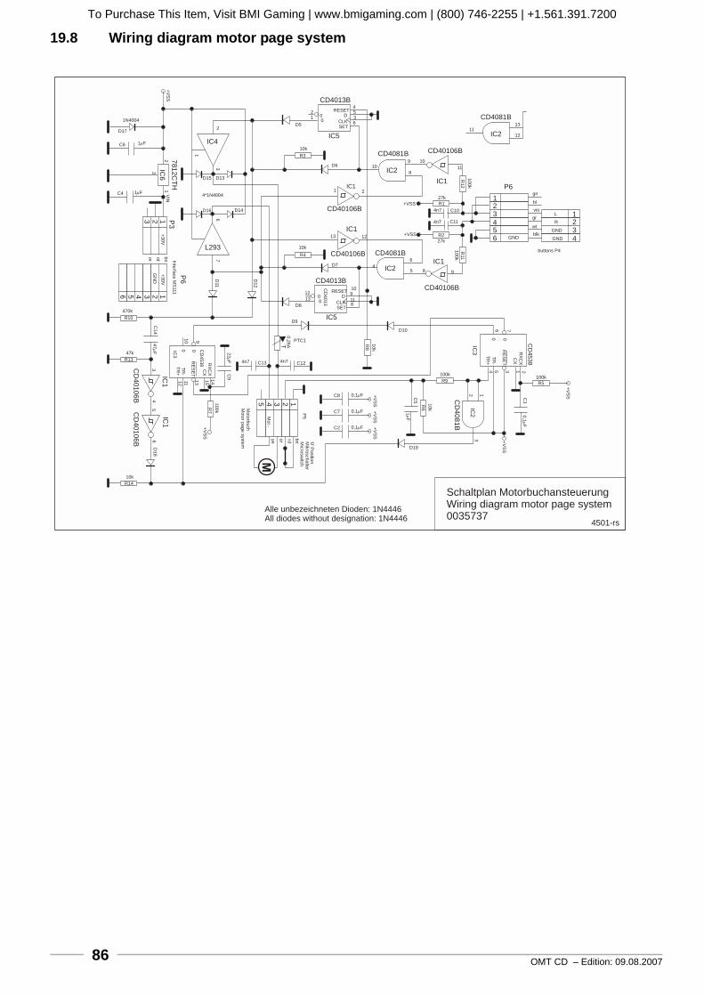
OMT CD – Edition: 09.08.200786
19.8 Wiring diagram motor page system
11
1
1
4
3
4
4
22
1
2
2
5
4
5
33
2
3
3
6
5
6
Alle unbezeichneten Dioden: 1N4446All diodes without designation: 1N4446
Schaltplan MotorbuchansteuerungWiring diagram motor page system0035737
T
IC5
CD4013B
IC5
CD4081B CD40106B
CD40106B
IC1
CD40106B CD4081B
CD40106B
IC1IC2
IC2
CD4013B
CD4081B
IC2
P6IC1
IC4
L293
7812C
TH
IC6
P3
P6
IC2
CD
4081B
CD
40106B
CD
40106B
IC1
IC1
1N4004
D17
C6 1 F
1 F
+V
SS
C4
2
D15 D13
1
3
2
3
1V
IN 4*1N4004
D16 D14
+3
0V
GN
D
+3
0V
10k
R4
67
D11
D1
2
bn
rd Inte
rface
MS
111
or
1213
D8
D9
PTC1
0,2
6A
910
C1
44
7F
470k
R10
47k
IC3
0 0
22
F
4n7 4n7C13 C12
C91
415
131112
34
5
TR
+T
R-
RE
SE
T
CD
45
38 RX
CX
CX
10
0k
R7
+V
SS
+V
SS
+V
SS
+V
SS
+V
SS
+V
SS
6D
18
10k
Mo
torb
uch
Mo
tor
pa
ge
syste
m
P5
bnrdorye
Mo
t-
R14
M
C8
C7
C2
0,1 F
0,1 F
0,1 F
Mik
rosch
alte
rM
icro
sw
itch
‘0’ P
ositio
n
D19
C5
1F
10
k
R6
R9
100k
2 13
IC3
CD
45
38
0 0
TR
+
TR
-
RE
SE
T
CX
RX
CX
21356 7
4
C1
0,1
F
10
k
R8
100k
R5
D10
0
0
0
0
RESET
RESET
D
D
CLK
CLK
SET
SET
8
9
11
10CD
40
13
D7
13 12
4
6
5 8 9
R11
10
0k
10k
R3
D6
2IC1
109
8
10
11
10
0k
R1
2
+VSS
27k
R1
4n7 C10
C114n7
R227k
+VSSGND
gn
bl
vio
gr
wt
blk
L
R
GND
GND
buttons P4
1112
13D5
12
4536
R13
1
4501-rs
To Purchase This Item, Visit BMI Gaming | www.bmigaming.com | (800) 746-2255 | +1.561.391.7200
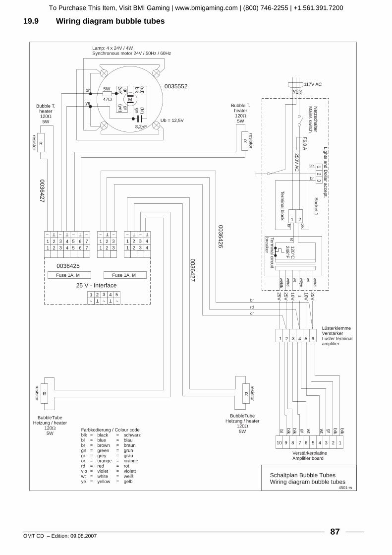
OMT CD – Edition: 09.08.2007 87
19.9 Wiring diagram bubble tubes
25 V - Interface
0036425
0035552
00
36
42
7
00
36
42
7
00
36
42
6
~
~
~~
~
~~
~
~~ ~
1
1
11
1
1
11
2
2
22
2
2
22
3
3
33
3
3
33
4
4
4
4
4
4
5
5
5
5
6
6
6
7
7
Fuse 1A, M Fuse 1A, M
R R
M
Lamp: 4 x 24V / 4WSynchronous motor 24V / 50Hz / 60Hz
Ub = 12,5V
8,2F
or
ye
5W
47
gr
(ye
)g
r(y
e)
(rd)
blk
(bl)
gn
Bubble T.heater1205W
BubbleTubeHeizung / heater
1205W
BubbleTubeHeizung / heater
1205W
Bubble T.heater1205W
resis
tor
resis
tor
117V AC
Ne
tzsch
alte
rM
ain
ssw
itch
Lig
hts
an
dD
olla
ra
cce
pt.
F6
,0A
25
0V
AC
12
0°C
24
8°F
25
V
10
VT
10
V
25
V
29
V
So
cke
t1
Te
rmin
alb
lock
Te
rmin
alcirc
uit
bre
ake
r
12
3
1 2
blk
blk
wt/b
lk
wt/rd
wt
wt/y
e
wt
wt/rd
gnwt
br
rd
blk
br
br
rd
or
R R
resis
tor
resis
tor
10 9 8 7 6 5 4 3 2 1
VerstärkerplatineAmplifier board
bl
blk
blk
gr
wt
wt
gr
blk
blk
LüsterklemmeVerstärkerLuster terminalamplifier
Farbkodierung / Colour codeblkblbrgngrorrdviowtye
==========
==========
blackbluebrowngreengreyorangeredvioletwhiteyellow
schwarzblaubraungrüngrauorangerotviolettweißgelb
Schaltplan Bubble TubesWiring diagram bubble tubes
4501-rs
To Purchase This Item, Visit BMI Gaming | www.bmigaming.com | (800) 746-2255 | +1.561.391.7200

OMT CD – Edition: 09.08.200788
19.10 Wiring diagram K99 - power supplyTo Purchase This Item, Visit BMI Gaming | www.bmigaming.com | (800) 746-2255 | +1.561.391.7200
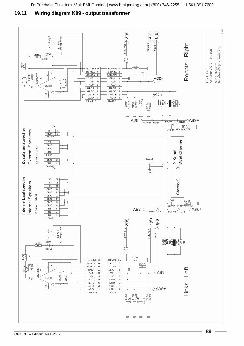
OMT CD – Edition: 09.08.2007 89
19.11 Wiring diagram K99 - output transformerTo Purchase This Item, Visit BMI Gaming | www.bmigaming.com | (800) 746-2255 | +1.561.391.7200
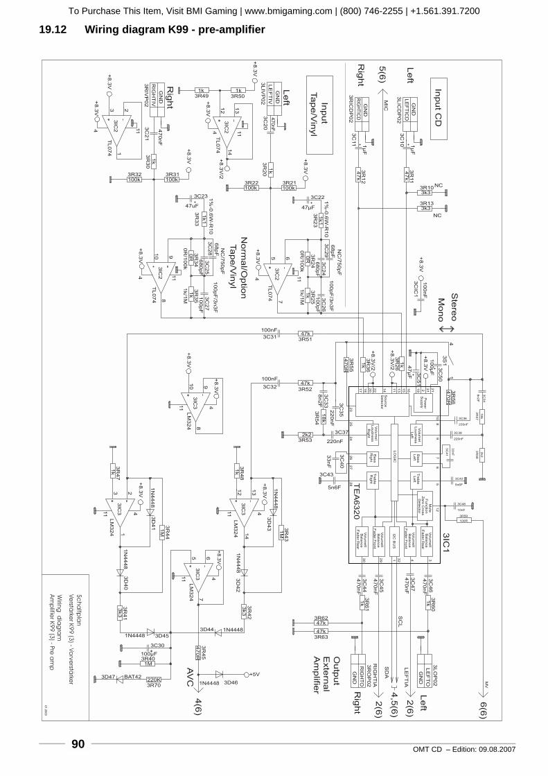
OMT CD – Edition: 09.08.200790
19.12 Wiring diagram K99 - pre-amplifierTo Purchase This Item, Visit BMI Gaming | www.bmigaming.com | (800) 746-2255 | +1.561.391.7200

OMT CD – Edition: 09.08.2007 91
19.13 Wiring diagram K99 - sound controlTo Purchase This Item, Visit BMI Gaming | www.bmigaming.com | (800) 746-2255 | +1.561.391.7200

OMT CD – Edition: 09.08.200792
19.14 Wiring diagram K99 - port ATo Purchase This Item, Visit BMI Gaming | www.bmigaming.com | (800) 746-2255 | +1.561.391.7200

OMT CD – Edition: 09.08.2007 93
19.15 Wiring diagram K99 - Mute To Purchase This Item, Visit BMI Gaming | www.bmigaming.com | (800) 746-2255 | +1.561.391.7200
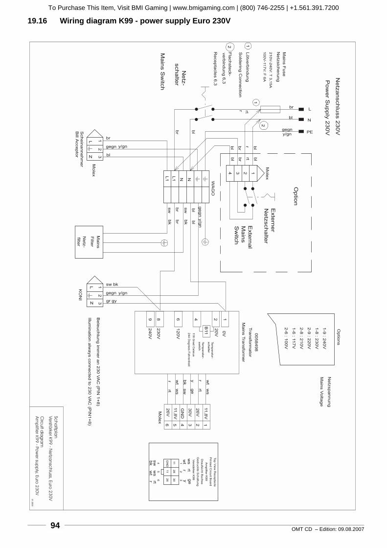
OMT CD – Edition: 09.08.200794
19.16 Wiring diagram K99 - power supply Euro 230VTo Purchase This Item, Visit BMI Gaming | www.bmigaming.com | (800) 746-2255 | +1.561.391.7200

OMT CD – Edition: 09.08.2007 95
19.17 Wiring diagram K99 - power supply UL/USA 117VTo Purchase This Item, Visit BMI Gaming | www.bmigaming.com | (800) 746-2255 | +1.561.391.7200
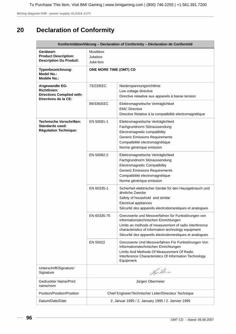
Wiring diagram K99 - power supply UL/USA 117V
OMT CD – Stand: 09.08.200796
20 Declaration of Conformity
Konformitätserklärung – Declaration of Conformity – Déclaration de Conformité
Geräteart:Product Description:Description Du Produit:
MusikboxJukeboxJuke-box
Typenbezeichnung:Model No.:Modèle No.:
ONE MORE TIME (OMT) CD
Angewandte EG-Richtlinien:Directives Complied with:Directives de la CE:
73/23/EEC NiederspannungsrichtlinieLow voltage directiveDirective relaative aux appareils à basse tension
89/336/EEC Elektromagnetische VerträglichkeitEMC DirectiveDirective Relative à la compatibilité electromagnétique
Technische Vorschriften:Standards used:Régulation Technique:
EN 50081-1 Elektromagnetische VerträglichkeitFachgrundnorm StöraussendungElectromagnetic compatibilityGeneric Emissions RequirementsCompatibilité electromagnétiqueNorme générique emission
EN 50082-2 Elektromagnetische VerträglichkeitFachgrundnorm StöraussendungElectromagnetic CompatibilityGeneric Emissions RequirementsCompatibilité electromagnétiqueNorme générique emission
EN 60335-1 Sicherheit elektrischer Geräte für den Hausgebrauch und ähnliche ZweckeSafety of household and similarElectrical appliancesSécurité des appareils electrodomestiques et analogues
EN 60335-75 Grenzwerte und Messverfahren für Funkstörungen von informationstechnischen EinrichtungenLimits an methods of measurement of radio interference characteristics of information technology equipmentSécurité des appareils electrodomestiques et analogues
EN 55022 Grenzwerte Und Messverfahren Für Funkstörungen Von Informationstechnischen EinrichtungenLimits And Methods Of Measurement Of Radio Interference Characteristics Of Information Technology Equipment.
Unterschrift/Signature/Signature
Gedruckter Name/Print name/nom
Jürgen Obermeier
Position/Position/Position Chief Engineer/Technischer Leiter/Directeur Technique
Datum/Date/Date 2. Januar 1995 / 2. January 1995 / 2. Janvier 1995
To Purchase This Item, Visit BMI Gaming | www.bmigaming.com | (800) 746-2255 | +1.561.391.7200

To Purchase This Item, Visit BMI Gaming | www.bmigaming.com | (800) 746-2255 | +1.561.391.7200

GermanyDeutsche Wurlitzer GmbHWurlitzerstraße 6D-32609 HüllhorstTel.: +49(0) 57 44 - 941-0Fax: +49(0) 57 44 - 941 [email protected]
Art.-Nr.: 0073254Wurlitzer® A Registered Trademark of the Gibson Guitar Corporation Edition 4708
R
To Purchase This Item, Visit BMI Gaming | www.bmigaming.com | (800) 746-2255 | +1.561.391.7200


![BM1弾 カードチェックリスト · 2020-06-17 · 1.89 d bmi-scp4[cp1 c] bmi-scp8[cp] bmi-hcpi bmi-scps[cpi a bmi cl bmi-scpi c] bmi-scp5[cp] c] bmi-cpi [cpi 12 bmi-cp2tcp]](https://static.fdocuments.net/doc/165x107/5f0d11867e708231d43885ac/bm1-fffffff-2020-06-17-189-d-bmi-scp4cp1-c-bmi-scp8cp.jpg)