
ON AERIAL INDOOR POSITION CONTROL AND SYSTEM … · Paparazzi, and others. ... of means, including...
10
Proceedings of ASME 2016 Dynamic Systems and Control Conference DSCC2016 October 12-14, 2016, Minneapolis, USA DSCC2016-9842 ON AERIAL INDOOR POSITION CONTROL AND SYSTEM INTEGRATION FOR QUADCOPTERS USING LIDARS AND INERTIAL MEASUREMENT UNITS Nathan Zimmerman, Kellen Carey, and Cristinel Ababei Department of Electrical and Computer Engineering Marquette University Milwaukee, Wisconsin 53233, USA Email: {nathan.zimmerman,kellen.carey,cristinel.ababei}@marquette.edu ABSTRACT The main contribution of this paper is to introduce a compu- tationally efficient iterative closest line (ICL) algorithm for de- termining indoor position drift of a quadcopter using minimal lidar data. In addition, we present the system-level design and implementation of a new quadcopter both as hardware and flight control algorithms. Such a platform allows us to develop and experiment new control and system optimization techniques. As an example, we discuss how the proposed ICL algorithm is used for position hold and control purposes by plugging it into the low level implementation of the flight control algorithm of the quadcopter. For testing and validation we use simulations with real world data. As part of the system-level design aspects, we present an investigation of the quadcopter power consumption. We are interested in power consumption because it is the major factor that determines the flight time of a typical quadcopter. We believe that this work is a contribution toward achieving better quadcopter design and control for indoor autonomous naviga- tion. 1 Introduction Recently, aerial multi-rotor or drone systems have been ap- plied in numerous applications such as surveillance, aerial pho- tography, and other general consumer use. Owing to their afford- ability and versatility, these applications continue to increase and much research has been done regarding their future applications. For example, Amazon Prime Air, an autonomous outdoor deliv- ery system, has received widespread media coverage. However, while outdoor applications for multi-rotor systems are numerous, indoor autonomous use has been less discussed in the available literature. That is in part because indoor autonomous control is more difficult than outdoors where access to the global position- ing system (GPS) is reliable. Also, minor positional drift out- doors is generally of less consequence than indoors where space is confined. Microelectromechanical systems (MEMS) based in- ertial measurement units (IMUs) alone have limited or no capac- ity to sense and prevent indoor positional drift. Consequently, a variety of solutions have been proposed to address this issue. A common such solution is to use infrared (IR) beacons and a net- work of cameras to tag the drone and to determine its absolute position. Another popular solution is to use an optical flow sen- sor attached to the bottom of the drone to reduce positional drift. However, these solutions generally are limited in their ability to maintain absolute control of position. An emerging approach for indoor autonomous position con- trol is the use of a lidar sensor. A lidar is is a scanning 2D laser range finder, which can provide accurate position information. Lidars have been increasingly utilized in various applications and their cost continues to decrease. An example application is the Neato XV, which is an autonomous vacuum cleaner robot [1]. This robot uses a lidar sensor to map and navigate the envi- ronment and employs the simultaneous mapping and localiza- tion (SLAM) algorithm. However, while SLAM performs well for ground based vehicles, it is more difficult to implement for aerial multi-rotor systems due to positional drift. Consequently, indoors SLAM for multi-rotor systems is an active area of re- search. Here, we see mostly studies that use lidars which cost thousands of dollars and utilize computationally expensive algo- 1 Copyright c 2016 by ASME
Transcript of ON AERIAL INDOOR POSITION CONTROL AND SYSTEM … · Paparazzi, and others. ... of means, including...
Proceedings of ASME 2016 Dynamic Systems and Control ConferenceDSCC2016
October 12-14, 2016, Minneapolis, USA
DSCC2016-9842
ON AERIAL INDOOR POSITION CONTROL AND SYSTEM INTEGRATION FORQUADCOPTERS USING LIDARS AND INERTIAL MEASUREMENT UNITS
Nathan Zimmerman, Kellen Carey, and Cristinel AbabeiDepartment of Electrical and Computer Engineering
Marquette UniversityMilwaukee, Wisconsin 53233, USA
Email: {nathan.zimmerman,kellen.carey,cristinel.ababei}@marquette.edu
ABSTRACTThe main contribution of this paper is to introduce a compu-
tationally efficient iterative closest line (ICL) algorithm for de-termining indoor position drift of a quadcopter using minimallidar data. In addition, we present the system-level design andimplementation of a new quadcopter both as hardware and flightcontrol algorithms. Such a platform allows us to develop andexperiment new control and system optimization techniques. Asan example, we discuss how the proposed ICL algorithm is usedfor position hold and control purposes by plugging it into thelow level implementation of the flight control algorithm of thequadcopter. For testing and validation we use simulations withreal world data. As part of the system-level design aspects, wepresent an investigation of the quadcopter power consumption.We are interested in power consumption because it is the majorfactor that determines the flight time of a typical quadcopter. Webelieve that this work is a contribution toward achieving betterquadcopter design and control for indoor autonomous naviga-tion.
1 IntroductionRecently, aerial multi-rotor or drone systems have been ap-
plied in numerous applications such as surveillance, aerial pho-tography, and other general consumer use. Owing to their afford-ability and versatility, these applications continue to increase andmuch research has been done regarding their future applications.For example, Amazon Prime Air, an autonomous outdoor deliv-ery system, has received widespread media coverage. However,while outdoor applications for multi-rotor systems are numerous,
indoor autonomous use has been less discussed in the availableliterature. That is in part because indoor autonomous control ismore difficult than outdoors where access to the global position-ing system (GPS) is reliable. Also, minor positional drift out-doors is generally of less consequence than indoors where spaceis confined. Microelectromechanical systems (MEMS) based in-ertial measurement units (IMUs) alone have limited or no capac-ity to sense and prevent indoor positional drift. Consequently, avariety of solutions have been proposed to address this issue. Acommon such solution is to use infrared (IR) beacons and a net-work of cameras to tag the drone and to determine its absoluteposition. Another popular solution is to use an optical flow sen-sor attached to the bottom of the drone to reduce positional drift.However, these solutions generally are limited in their ability tomaintain absolute control of position.
An emerging approach for indoor autonomous position con-trol is the use of a lidar sensor. A lidar is is a scanning 2D laserrange finder, which can provide accurate position information.Lidars have been increasingly utilized in various applications andtheir cost continues to decrease. An example application is theNeato XV, which is an autonomous vacuum cleaner robot [1].This robot uses a lidar sensor to map and navigate the envi-ronment and employs the simultaneous mapping and localiza-tion (SLAM) algorithm. However, while SLAM performs wellfor ground based vehicles, it is more difficult to implement foraerial multi-rotor systems due to positional drift. Consequently,indoors SLAM for multi-rotor systems is an active area of re-search. Here, we see mostly studies that use lidars which costthousands of dollars and utilize computationally expensive algo-
1 Copyright c© 2016 by ASME

rithms that require high performance processors and GB of RAMmemory.
To address these issues, in this paper, we focus on using alow cost lidar for quadcopter position control and develop practi-cal algorithms that can be run on sub GHz ARM processors withminimal RAM memory. Specifically, our main contributions in-clude: 1) We introduce a computationally efficient algorithm fordetermining position drift with minimal lidar data, 2) We vali-date this algorithm with data from an affordable lidar sensor, 3)We integrate the proposed algorithm within the main flight con-trol algorithm of our in-house built quadcopter, and 4) We presentalso a discussion of energy consumption in drone systems, whichhas not been done in the prior available literature.
2 Related WorkDrones, particularly quadcopters, have been studied by aca-
demic, commercial, and hobbyist communities. Quadcopters arethe most popular due to their very low moment of inertia and sixdegrees of freedom, which results in better stability and agilityof the quadcopter. A strong and active online community ofprofessionals and hobbyists alike are contributing to the body ofknowledge regarding the hardware and software development ofdrones.
2.1 Related Work on Drone Modeling and Develop-ment
Looking at the available literature, we find previous stud-ies that can be classified into several different types of contri-butions: studies that investigate different system modeling andcontrol techniques, trajectory planning algorithms, autonomousdesigns, and system hardware development using off-the-shelf orin-house components.
As examples in the first category, various control techniqueshave been studied, including PID control [2,3], backstepping [4],nonlinear H∞ [5], and Kalman filtering [6].
Prior works in the second category deal with trajectory plan-ning, which is very challenging. While most discussions assumethat the trajectory exists, the question of the feasibility of a giventrajectory has been studied too. Planning can be solved in twosteps. In the first step, trajectories containing no time informationare calculated from a class of motion primitives. Then, the trajec-tory is parametrized in time by choosing the trajectory speed suchthat dynamic feasibility constraints are enforced. An algorithmthat allows the calculation of flight trajectories by combining theabove two steps for quadrocopters is presented in [7].
In the case of autonomous flight, processing and decisionmaking has to be done on board. Operating at the optimaltradeoff between flight performance, sensors, and computing re-sources has its own challenges. Steps towards addressing thesechallenges are studied in [8] within the context of indoor explo-ration inside a house of known shape and dimensions in order todetect objects and be able to return outside.
The online community has been very active and numerousonline articles report drone designs developed on a large vari-ety of hardware platforms. In addition, we see an increasingnumber of commercial offerings. The survey in [9] presents asummary of publicly available open-source projects on quadro-tor unmanned aerial vehicles, including Arducopter, Openpilot,Paparazzi, and others. Because some commercial offerings suchas the AR.Drone provide application programming interfaces(APIs), they can be used for educational and research purposeswith focus on position stabilization, object following, and au-tonomous navigation [10].
Further details on the modeling and control of quadcopterscan be found in the excellent tutorial in [11]. Several key in-sights discussed in this tutorial include: 1) blade flapping andinduced drag are fundamental effects that are of high importancein understanding the natural stability of quadrotors and how stateobservers operate, 2) smaller quadrotors can produce faster an-gular accelerations while the linear acceleration is at worst unaf-fected by scaling, 3) position estimation can be done via a varietyof means, including GPS, acoustic, laser-ranging, infrared, andvision/camera systems, and 4) usually a hierarchical control ap-proach is used for quadrotors to control the rotor rotational speed(lowest level), vehicle attitude, and position along a trajectory.
2.2 Related Work on Lidar Usage in Drone Develop-ment
The key state estimates required for the control of a quadro-tor include its height, attitude, angular velocity, and linear veloc-ity [11]. The attitude and angular velocity are the most impor-tant because they are the primary variables used in attitude con-trol. The most basic instrumentation carried by any quadrotoris an inertial measurement unit (IMU) often augmented by someform of height measurement, either acoustic, infrared, baromet-ric, or laser based. A typical IMU includes a three-axis rate gyro,three-axis accelerometer, and three-axis magnetometer. The ac-celerometers and magnetometers can be used to provide absoluteattitude information on the vehicle while the rate gyroscope pro-vides complementary angular velocity measurements. Becausewe place special emphasis on the usage of lidar data for positioncontrol of drones, we review here also literature related to thistopic.
There has been a lot of work done using lidar for position-ing of unmanned ground vehicles and robots [12–14]. However,there is little prior work done on using lidars directly for dronecontrol. The only previous work that we are aware is [15]. Thisdissertation is a demonstration of using a lidar indoors to map inreal time the environment using the iterative closest point (ICP)technique fused with IMU data. This approach is the closest toour work. In contrast, we use a less powerful embedded proces-sor with only 64KB or RAM versus 2GB and focus primarily onposition/localization control compared to simultaneous mappingand localization.
2 Copyright c© 2016 by ASME
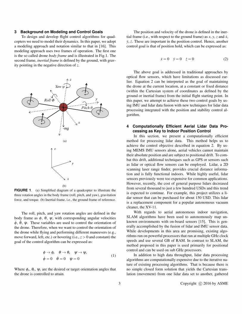
3 Background on Modeling and Control GoalsTo design and develop flight control algorithms for quad-
copters we need to model their dynamics. In this paper, we adopta modeling approach and notation similar to that in [16]. Thismodeling approach uses two frames of operation. The first oneis the so called drone body frame and is illustrated in Fig.1. Thesecond frame, inertial frame is defined by the ground, with grav-ity pointing in the negative direction of z.
3/17/2016
1
-mg
(a)
3/17/2016
1
z
y
x
(b)FIGURE 1. (a) Simplified diagram of a quadcopter to illustrate thethree rotation angles in the body frame (roll, pitch, and yaw), gravitationforce, and torque. (b) Inertial frame, i.e., the ground frame of reference.
The roll, pitch, and yaw rotation angles are defined in thebody frame as φ , θ , ψ , with corresponding angular velocitiesφ , θ , ψ . These variables are used to control the orientation ofthe drone. Therefore, when we want to control the orientation ofthe drone while flying and performing different maneuvers (e.g.,move forward, left, etc.) or hovering (i.e., z > 0 and constant) thegoal of the control algorithm can be expressed as:
φ → φr θ → θr ψ → ψr
φ = 0 θ = 0 ψ = 0(1)
Where φr, θr, ψr are the desired or target orientation angles thatthe drone is controlled to attain.
The position and velocity of the drone is defined in the iner-tial frame (i.e., with respect to the ground frame) as x, y, z and x,y, z. These are important in the position control. Hence, anothercontrol goal is that of position hold, which can be expressed as:
x = 0 y = 0 z = 0 (2)
The above goal is addressed in traditional approaches byoptical flow sensors, which have limitations as discussed ear-lier. Equation 2 can be interpreted as the goal of maintainingthe drone at the current location, at a constant or fixed distance(within the Cartesian system of coordinates as defined by theground or inertial frame) from the initial flight starting point. Inthis paper, we attempt to achieve these two control goals by us-ing IMU and lidar data fusion with new techniques for lidar dataprocessing integrated with the position and stability control al-gorithm.
4 Computationally Efficient Aerial Lidar Data Pro-cessing as Key to Indoor Position ControlIn this section, we present a computationally efficient
method for processing lidar data. This method helps us toachieve the control objective described in equation 2. By us-ing MEMS IMU sensors alone, aerial vehicles cannot maintaintheir absolute position and are subject to positional drift. To com-bat this drift, additional techniques such as GPS or sensors suchas lidar or optical flow sensors can be employed. Lidar, a 2Dscanning laser range finder, provides crucial distance informa-tion and is fully functional indoors. While highly useful, lidarsensors previously were too expensive for common applications.However, recently, the cost of general purpose lidars decreasedfrom several thousand to just a few hundred USDs and this trendis expected to continue. For example, this project utilizes a li-dar sensor that can be purchased for about 150 USD. This lidaris a replacement component for a popular autonomous vacuumcleaner, the XV-11.
With regards to aerial autonomous indoor navigation,SLAM algorithms have been used to autonomously map un-known environments with on-board sensors [15]. This is gen-erally accomplished by the fusion of lidar and IMU sensor data.While developments in this area are promising, existing algo-rithms run on powerful processors that run at multiple GHz clockspeeds and use several GB of RAM. In contrast to SLAM, themethod proposed in this paper is used primarily for positionalcontrol and can be used on sub GHz processors.
In addition to high data throughput, lidar data processingalgorithms are computationally expensive due to the iterative na-ture of existing processing algorithms. That is because there isno simple closed form solution that yields the Cartesian trans-lation (movement) from one lidar data set to another, gathered
3 Copyright c© 2016 by ASME

during two consecutive revolutions. To illustrate that, we use theexample lidar data set from Fig.2.
3/23/2016
1
y
x
Drone moves from point a to point b
b a
(a)
-5000 -4000 -3000 -2000 -1000 0 1000mm
-3000
-2000
-1000
0
1000
2000
3000
mm
Lidar Room Plot
0.5 1 1.5 2 2.5 3 3.5 4Time (seconds)
(b)
FIGURE 2. (a) Sketch of room inside which lidar experiments aredone. Lidar sensor is moved in the x direction. (b) The data cloudscollected from the lidar sensor for each revolution during the movementfrom point a to point b.
The lidar outputs data in polar coordinates, (r∠θ), whichwe then convert to Cartesian coordinates, x = r · cos(θ), y =r · sin(θ). These coordinates are used to compute or estimatethe displacements in the x and y directions, ∆x and ∆y, betweenmultiple revolutions of the lidar sensor. In particular, we areinterested in computing these displacements between consecu-tive revolutions because these displacements help us to find ifthe drone drifted or not within the time duration between thetwo lidar sensor revolutions. The challenge is that the estimationcannot be done by directly summing up the individual displace-ments of different points from the data set collected during anyone given revolution. We illustrate this issue with the help of theexample from Fig.3.a. Here, the mean of the resulting displace-ment vector has components in both x and y. However, the truedisplacement is only in the x direction. To identify that correctly,we need a technique that knows to reject and invalidate false in-dividual point displacements such as ∆y2 and ∆y3 in Fig.3.b.
3/31/2016
1
P1,1=(x1,1, y1,1)
Data point collected during revolution 0
Lidar
Data point collected during revolution 1
P1,2=(x1,2, y1,2)
P1,3=(x1,3, y1,3)
P1,4=(x1,4, y1,4)P1,5P1,6
P0,6 P0,5 P0,4
P0,3
P0,2
P0,1
Displacement
vector
Δy3
Δy2
(a)
3/31/2016
1
Lidar
(x3, y3)PCL
Desired displacement
vector
(x1, y1)
(x2, y2)
(b)FIGURE 3. (a) Illustration of lidar reference frame issue observedduring a lateral movement in the x direction of the inertial frame. Inthis diagram, points Prevolution,index represent the data points providedby the lidar at different locations (indicated via index) during two con-secutive revolutions indicated as revolution = 0 and revolution = 1. (b)The desired resulting displacement vector is obtained with the proposedtechnique, which uses the so called closest point, PCL, defined on a lineformed by two closest points collected during the previous revolution ofthe lidar.
In this paper, we propose an algorithm to address this issue.This algorithm is computationally efficient and targeted at ARMCortex based processors with only 64KB of RAM memory. Thisalgorithm is described in the next section.
4.1 Proposed Iterative Closest Line (ICL) MethodHere, we describe a simple, accurate, and computationally
efficient method to estimate the overall displacements ∆x and ∆ybetween two consecutive revolutions of the lidar sensor. Thismethod, which we refer to as the iterative closest line (ICL), canbe seen as a variant of the iterative closest point (ICP) technique[17–19]. The pseudocode description of the proposed methodis shown in Fig.4. Essentially, it calculates the displacements∆x,∆y between two consecutive revolutions of the lidar sensor.
ICL uses a point to line metric in order to determine the over-all resulting displacement between two point cloud sets. Thispoint to line metric represents the squared error that is mini-
4 Copyright c© 2016 by ASME

Algorithm: Gradient descent based ICL Method1: Input: Cloud data sets of two consecutive revolutions, k−1, k2: Output: ∆xk, ∆yk for second revolution, k3: for u← 1 to n do // n: number of iterations of algorithm4: for i← 1 to 360 do // measurements per revolution5: δxk = δxk +(xk,i− xCL)6: δyk = δyk +(yk,i− yCL)7: end for8: for i← 1 to 360 do // simultaneous update all xk,i,yk,i9: xk,i = xk,i−αδxk // α is the learning rate
10: yk,i = yk,i−αδyk11: end for12: ∆xk = ∆xk +δxk // accumulate displacement13: ∆yk = ∆yk +δyk14: end for
FIGURE 4. Pseudocode of the proposed ICL method. It uses a gradi-ent descent based technique, which employs the point to line metric, tofind out the displacements.
mized with a gradient descent based algorithm [20]. The point toline metric error for a point Pk,i(xk,i,yk,i) from the point cloud setcollected during revolution k and assigned index i is denoted asJk,i and described by the following equation:
Jk,i = (xk,i− xCL)2 +(yk,i− yCL)
2 (3)
Point PCL(xCL,yCL) represents the closest point with respectto a point to line metric. This point is calculated based on a lineformed by the two closest points from the previous lidar revolu-tion and a current data point, Pk,i(xk,i,yk,i). An example of sucha point is shown in Fig.3.b. Jk,i represents basically the squareddistance between points Pk,i and PCL. The summation of all suchdistances for all points from a point cloud set gives the squarederror that is minimized with a gradient descent based algorithm.
To calculate the coordinates (xCL,yCL) for each data point ofa lidar revolution, first, a search must be performed to determinethe two previous closest points to a new sample point. Next stepis to define a line between these points using the general line formequation. This is used as opposed to the slope-intercept form inorder to avoid potential divisions by 0. In this way, we find theclosest point on that line to the new data point as described bythe following well known equations:
xCL =b(bx3−ay3)−ac
a2 +b2
yCL =a(−bx3 +ax3)−bc
a2 +b2
a = y2− y1, b = x1− x2, c =−by1−ax1
(4)
Where (x1,y1) and (x2,y2) are the two closest points on a previ-
ous lidar revolution with respect to a new point (x3,y3) as illus-trated in Fig.3.b. The gradient descent technique will minimizethe summation of all Jk,i. For that purpose, it uses the followingquantities for its update laws from Fig.4:
δxk =N
∑i=1
∂Jk,i
∂x=
N
∑i=1
(xk,i− xCL)
δyk =N
∑i=1
∂Jk,i
∂y=
N
∑i=1
(yk,i− yCL)
(5)
To estimate the overall displacement from an initial startingpoint (i.e., many revolutions ago), we accumulate or integrate∆x,∆y across all revolutions. As an example, the traditional ICPand proposed ICL algorithms are used to estimate the overall dis-placements ∆x and ∆y using the dataset from Fig.2.b. The resultsof this estimation are reported in Fig.5.
0 5 10 15 20 25 30 35Lidar Revolutions
0
200
400
600
Dis
plac
emen
t (m
m)
ICL Vs ICP Integration Results
"x ICLs"x ICL"x ICPs"x ICPx Final Measured
FIGURE 5. Demonstration of ICP and ICL algorithms using thedataset from Fig.2.b.
We can see that the proposed ICL algorithm performs betteras its accumulated error is smaller than the error obtained withthe ICP algorithm. Our method can be applied on an embeddedmicroprocessor in real time without large matrix inversions orlarge memory requirements. Note that the ICP algorithm can stillbe successfully utilized as reported in [15], but it would requirea larger number of data points collected during a single revolu-tion of the lidar. In addition, it also needs a more expensive andpowerful processor to be able to handle larger numbers of pointsper revolution.
4.2 A Technique for Outliers and Dynamic Object Re-jection
To improve the accuracy and reliability of the proposed ICLalgorithm, we implement an outlier rejection technique, which is
5 Copyright c© 2016 by ASME

described in this section. Such a technique is crucial for the prac-tical application of the proposed ICL algorithm in a real worldsetup. This is so because without a rejection mechanism, signif-icant positional error can accumulate over time and mislead theposition control part of the flight control algorithm. Outliers caninclude spurious lidar measurements as well as data points cor-responding to highly dynamic objects such as humans. The pro-posed outlier rejection technique is robust yet computationallyefficient. Its idea is to use the previous estimates ∆xk−1,∆xk−1and checks if the cost of the current point Jk,i is significantlylarger than (∆x2
k−1 +∆y2k−1), case in which the point is rejected.
We have tested this technique with good practical results. Forexample, for the dataset shown in Fig.6, the total error in esti-mating the displacements is very small as reported in Fig.7. Thisfigure also shows the performance of the ICL algorithm withoutan outlier rejection technique.
-5000 -4000 -3000 -2000 -1000 0 1000mm
-3000
-2000
-1000
0
1000
2000
3000
mm
Lidar Room Plot
0.5 1 1.5 2 2.5 3 3.5 4 4.5 5Time (seconds)
FIGURE 6. Lidar data with human movement in a stationary room.
Lidar Revolutions0 10 20 30 40 50 60 70 80 90
Dis
plac
emen
t (m
m)
-100
-50
0
50
100Rejection Method of Dynamic Objects
s"x ICL w/ Rejections"x ICL
FIGURE 7. Dataset in Fig.6 with and without dynamic rejection.
4.3 Integration into the Main Flight Control AlgorithmIn this section, we describe how the proposed ICL algorithm
is integrated with the main flight control algorithm of the quad-copter drone. This is illustrated in Fig.8, where the lidar dataprovided by the lidar sensor is fed into the ICL algorithm, whichthen computes the displacement estimates ∆x and ∆y. In the ab-sence of user input (which is received from the user’s hand-heldRC remote controller as φr,θr,ψr,hr) the objective of the flightcontrol algorithm is to hold the position of the quadcopter. In thiscase, the displacement estimates ∆x and ∆y are used to achieveposition hold by eliminating positional drift.
3/31/2016
1
Lidar data
ψIMU
Φr
θr
PID
PID
ICL
Algorithm
Δx
Δy
0
0
PID
PID
ΦIMU
θIMU
PIDψr
hSonar
PIDhr
Σ
RC
Remote
Φr θrψr hr
ψIMUΦIMU θIMU hSonar
Lidar data
Flight Control Algorithm
(Software)
ESCs
Drone
(Hardware)
S
S
S
S
FIGURE 8. Flight control algorithm in the overall quadcopter system.
As the primary control technique, the flight control algo-rithm employs several proportional integral derivative (PID) con-trollers to control the orientation angles φ ,θ ,ψ and the height h.Basically, the role of these PID controllers is to drive φ ,θ ,ψ andh to the desired target values. The PID controllers that use theinputs ∆x and ∆y are responsible with the elimination of posi-tional drift. For height control, data from a sonar distance sensoris utilized. The PID block with input hSonar controls the heightof the quadcopter.
In Fig.9, S represents the vector of individual motor speeds[S1,S2,S3,S4] as calculated by each of the four PID blocks. Thecalculation of S by each PID block is dependent on the physicsbased model of the quadcopter. Example derivations of themodel can be found in [16] and are out of scope for this paper.
The flight control algorithm from Fig.8 was tested and val-idated through simulations using a physics based model for thequadcopter. To simulate positional drift, external forces were ap-plied to the quadcopter frame. For example, the plot in Fig.9shows how θ ,φ are attained by the PID controllers that use ∆x
6 Copyright c© 2016 by ASME

and ∆y as inputs. While our extensive simulations verify the cor-rect operation of the overall flight control algorithm, we are cur-rently working on the physical implementation and integration ofthe lidar and sonar sensors on the quadcopter. This is a work inprogress.
0 200 400 600 800 1000Time (ms)
-0.2
0
0.2
0.4
0.6
mm
/s
Lidar Control System Results
3
?"x"y
-2
0
2
4
6
degr
ees
FIGURE 9. Plot showing how the flight control algorithm from Fig.8drives ∆x and ∆y to 0 in order to eliminate positional drift.
5 Hardware Implementation - System Integration As-pectsIn this section, we describe the implementation of our in-
house built quadcopter drone. Specifically, we discuss systemintegration and energy consumption aspects.
5.1 Overall System IntegrationIn building a drone, one must decide whether to do it using
off-the-shelf components or to design and build it from scratch.The issue with systems built using off-the-shelf components isthat, while much easier, we have limited capability in customiz-ing the system and in developing new flight control algorithms.On the other hand, designing a drone system from scratch of-fers flexibility in any design aspect: we can integrate into thesystem any microcontroller unit (MCU) and sensors we wouldlike, we can customize the hardware (at the PCB level) to al-low us to perform in depth performance and energy consumptionstudies, and we can investigate any novel idea for flight controlalgorithms without being limited by restrictive vendor specificapplication programming interfaces (APIs). In this project, wedecided to implement the entire system from scratch because wewere particularly interested in several design exploration direc-tions including: using specific IMU and lidar sensors, investi-gating energy consumption, and experimenting with new flightcontrol algorithm ideas.
Designing and building a quadcopter from scratch is achallenging undertaking. That is because the quadcopter sys-tem combines several hardware (HW) electronic and mechan-
ical components as well as firmware components as shown inFig.10.a. The four brushless motors are supplied with power andcontrolled by the four electronic speed controllers (ESCs). Theflight controller is responsible with tasks including data fusionof data from sensors (inertial measurement unit, IMU, lidar, etc.)and the primary flight control algorithm. The remote control ofthe drone is done via a custom RF hand-held controller, whichcommunicates with the radio block from Fig.10.a. The batterysupplies power to all components on board of the quadcopter.As software (SW) components, the quadcopter system has twoprograms (shown as Firmware 1 and Firmware 2 in Fig.10.a),which implement the main flight control algorithm and the con-trol algorithm that runs of on the four ESCs.
Each of the four ESCs controls an individual brushless di-rect current (BLDC) motor. The method that we use to controleach of the motors is using the so called back electromotive force(back-EMF) technique [21–23]. The key to BLDC commutationis to sense the rotor position, then energize the phases that willproduce the most amount of torque. The rotor travels 60 electri-cal degrees per commutation step. The appropriate stator currentpath is activated when the rotor is 120 degrees from alignmentwith the corresponding stator magnetic field, and then deacti-vated when the rotor is 60 degrees from alignment, at which timethe next circuit is activated and the process repeats [22].
Due to space limitations we cannot provide here comprehen-sive datasheet specifications of the individual components thatwe used in building our in-house drone. Instead we created awebsite to document in detail both the hardware and software,which we make publicly available as open source [26]. We dohowever, present specifications of the lidar device that we use inour experiments in the next section.
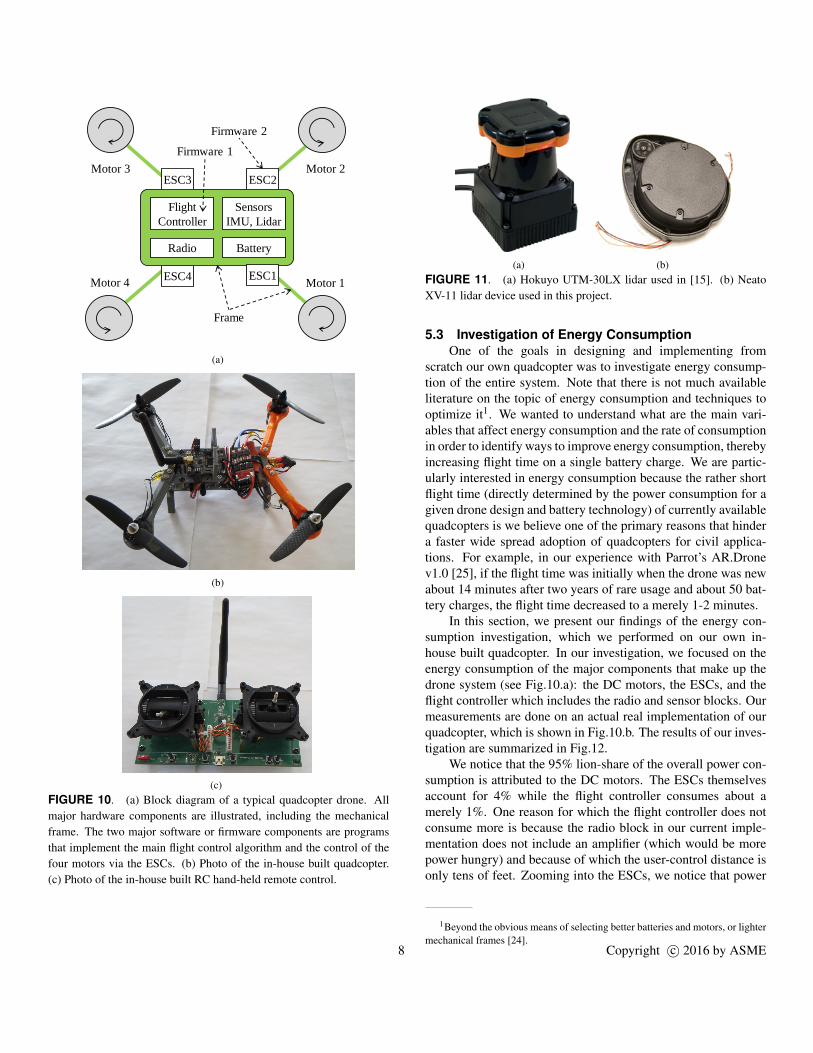
5.2 Lidar SpecificationsIn this section, we present the specifications of the lidar de-
vice that we use, XV-11, in order to compare it with the HokuyoUTM-30LX lidar that is used by the study in [15]. The pho-tographs of these two lidar devices are shown in Fig.11 while thetechnical specifications are presented in Table 1. We note that theXV-11 lidar is significantly inferior, however it is much cheaperand convenient especially during hardware prototyping.
TABLE 1. Specifications of the two lidars from Fig.11.
Lidar device: Hokuyo UTM-30LX Neato XV-11
Points per revolution 1,440 360
Revolution speed (ms) 25 250
Max range (m) 30 4
Cost (USD) 4,825 150
7 Copyright c© 2016 by ASME
3/21/2016
1
Motor 1
Flight
Controller
ESC1
ESC2ESC3
ESC4
Sensors
IMU, Lidar
BatteryRadio
Motor 2
Motor 4
Motor 3
Frame
Firmware 1
Firmware 2
(a)
(b)
(c)FIGURE 10. (a) Block diagram of a typical quadcopter drone. Allmajor hardware components are illustrated, including the mechanicalframe. The two major software or firmware components are programsthat implement the main flight control algorithm and the control of thefour motors via the ESCs. (b) Photo of the in-house built quadcopter.(c) Photo of the in-house built RC hand-held remote control.
(a) (b)FIGURE 11. (a) Hokuyo UTM-30LX lidar used in [15]. (b) NeatoXV-11 lidar device used in this project.
5.3 Investigation of Energy ConsumptionOne of the goals in designing and implementing from
scratch our own quadcopter was to investigate energy consump-tion of the entire system. Note that there is not much availableliterature on the topic of energy consumption and techniques tooptimize it1. We wanted to understand what are the main vari-ables that affect energy consumption and the rate of consumptionin order to identify ways to improve energy consumption, therebyincreasing flight time on a single battery charge. We are partic-ularly interested in energy consumption because the rather shortflight time (directly determined by the power consumption for agiven drone design and battery technology) of currently availablequadcopters is we believe one of the primary reasons that hindera faster wide spread adoption of quadcopters for civil applica-tions. For example, in our experience with Parrot’s AR.Dronev1.0 [25], if the flight time was initially when the drone was newabout 14 minutes after two years of rare usage and about 50 bat-tery charges, the flight time decreased to a merely 1-2 minutes.
In this section, we present our findings of the energy con-sumption investigation, which we performed on our own in-house built quadcopter. In our investigation, we focused on theenergy consumption of the major components that make up thedrone system (see Fig.10.a): the DC motors, the ESCs, and theflight controller which includes the radio and sensor blocks. Ourmeasurements are done on an actual real implementation of ourquadcopter, which is shown in Fig.10.b. The results of our inves-tigation are summarized in Fig.12.
We notice that the 95% lion-share of the overall power con-sumption is attributed to the DC motors. The ESCs themselvesaccount for 4% while the flight controller consumes about amerely 1%. One reason for which the flight controller does notconsume more is because the radio block in our current imple-mentation does not include an amplifier (which would be morepower hungry) and because of which the user-control distance isonly tens of feet. Zooming into the ESCs, we notice that power
1Beyond the obvious means of selecting better batteries and motors, or lightermechanical frames [24].
8 Copyright c© 2016 by ASME

Motor
Consumption
95%
ESCs
4%
Flight Controller
1%
Drone Power Consumption
(a)
FET Losses
82%
Micro
7%
Gate
Drivers
3%
LDO
8%
ESC Power Consumption
(b)
Micro
12%
IMU
12%
Radio
16%
LDO
60%
Flight Controller Power Consumption
(c)FIGURE 12. (a) Breakdown of the power consumption among themain components of the quadcopter drone system. (b) Breakdown ofthe power consumption at the level of the ESCs. (c) Breakdown of thepower consumption at the level of flight controller.
is dissipated as losses primarily into the field effect transistors(FETs, i.e., commutation switches) and the low-dropout (LDO)regulators. The LDO regulator is also accounting for the majorityof the power consumed by the flight controller.
Obviously, one could reduce power consumption by select-ing high efficiency power converters and high performance FETs(i.e., low ON resistance) and thus minimize losses. Additionally,one could decrease the weight of the whole system by using lightweight materials for the frame. Furthermore, high performanceDC motors and propellers and improved battery technology (i.e.,small volume and high energy capacity) would help to improvethe power consumption profile. However, once these hardwaredesign decisions are made2, the question is: Is there anythingelse that one can do to improve the power consumption profile,and thereby increase the flight time?
Looking at the pie-chart from Fig.10.a, one would think thatnot too much could be done aside from selecting better motors.However, the view offered by the charts in Fig.10 is only partial.In other words, these breakdown charts only tell us which arethe major contributors to the power consumption of the overallquadcopter system, but they do not capture how fast or at whatrate energy is consumed from the fixed capacity battery, whichis truly directly impacting the battery state of charge and therebythe duration of the flight time. Currently, we do not have test and
2Indeed, one can assume that the best hardware components are used; mostlikely at higher financial costs.
validation results of what we suspect might be the only factor un-der our control which could have a significant impact on the rateof battery energy depletion. Aside from the type of maneuvers orflight characteristics3, the quadcopter performs and aerial condi-tions (such as wind or air drifts), we suspect, based on our in-sights gained while developing the current quadcopter prototype,that the actual flight control algorithm (stabilization and position-ing) may play a significant role in how fast energy is consumedfrom the battery. Our insight essentially says that the amount ofenergy and the rate of its consumption is less for flight controlalgorithms that are more optimal in the sense that the stabiliza-tion portion is smoother and less jittery. When such stabiliza-tion is wobbly and the system is on the verge of being unstable(the quadcopter would flip in such unstable mode of operation),the motors are forced to operate at faster speeds and the speedsare changed more often (i.e., motors spend more time in tran-sient like operation mode). Such operation modes place a biggerburden on motors, which thus consume energy faster. Note thatjittery flight can also be affected by the imperfections and dif-ferences between motors and propellers themselves, which canintroduce difference between the current drawn by the motors.We suspect that better flight control algorithms can impact therate at which energy is consumed and thus on the battery andflight time. A more in depth investigation of this is left to ourfuture work.
6 Conclusion and Future WorkWe introduced a computationally efficient iterative closest
line (ICL) algorithm for determining indoor position drift of aquadcopter. We presented details of the implementation of theproposed algorithm as well as of a technique for outlier and dy-namic object rejection from lidar data clouds. We validated theproposed algorithm using simulations with real world data. Fur-thermore, we discussed how the proposed ICL algorithm wasintegrated into the flight control algorithm of an in-house builtquadcopter drone. This integration was verified in simulation.Finally, we discussed system-level design and implementationaspects of the quadcopter, including an investigation of the quad-copter power consumption.
While the the proposed ICL algorithm for position controlhas been validated on real world data and its testing, as part ofthe overall flight control algorithm, was done in simulation, andwhile the in-house drone is completed, we still have to physicallyplace the lidar sensor on the drone and perform lidar and IMUdata fusion. This is part of our ongoing and future work.
3For example, if a quadcopter keeps some forward motion at all times, itrequires much less power than hovering. This is attributed to the so called heli-copter translational lift phenomenon.
9 Copyright c© 2016 by ASME

AcknowledgmentThis work was supported in part by the Department of Elec-
trical and Computer Engineering at Marquette University.
REFERENCES[1] Neato Robotics, LaserSmart Mapping & Naviga-
tion, 2016, https://neatorobotics.com/lasersmart-mapping-navigation
[2] A.L. Salih, M. Moghavvemi, H.A.F. Mohamed, and K.S.Gaeid, “Flight PID controller design for a UAV quadro-tor," Scientific Research and Essays, vol. 5, pp. 3360-3367, 2010.
[3] L. Argentim, W. Contrimas, P.E. Santos, and R. Aguiar,“LQR and LQR-PID on a quadcopter platform," IEEE Int.Conference on Electronics, Informatics and Vision, 2013.
[4] T. Madani and A. Benallegue, “Backstepping control for aquadrotor helicopter," IEEE/RSJ Int. Conf. on IntelligentRobots and Systems, 2006.
[5] G.V. Raffo, M.G. Ortega, and F.R. Rubio, “An inte-gral predictive/nonlinear H infinity control structure fora quadrotor helicopter," Automatica, vol. 46, pp. 29-39,2009.
[6] M. Jun, S.I. Roumeliotis, and G.S. Sukhatme, “State esti-mation of an autonomous helicopter using Kalman filter-ing," Intelligent Robots and Systems, 1999.
[7] M. Hehn and R. D’Andrea, “Quadrocopter trajectory gen-eration and control," IFAC World Congress, 2011.
[8] T. Tomic et al., “Toward a fully autonomous UAV: re-search platform for indoor and outdoor urban search andrescue," IEEE Robot. Autom. Mag., vol. 19, no. 3, pp. 46-56, Sep. 2012.
[9] H. Lim, J. Park, D. Lee, H.J. Kim, “Build your ownquadrotor: open-source projects on unmanned aerial ve-hicles" IEEE Robot. Autom. Mag., 2012.
[10] T. Krajnik, V. Vonasek, D. Fiser, and J. Faigl, “AR-Droneas a platform for robotic research and education" EurobotConference, 2011.
[11] R. Mahony, V. Kumar, and P. Corke “Multirotor aerial ve-hicles: modeling, estimation, and control of quadrotor,"IEEE Robot. Autom. Mag., vol. 19, no. 3, pp. 20-32, Sep.2012.
[12] Y. Zhang, J. Wang, X. Wang, C. Li, and L. Wang, “3DLIDAR-based intersection recognition and road boundarydetection method for unmanned ground vehicle," IEEEInt. Conf. on Intelligent Transportation Systems(ITSC),2015.
[13] D. Jeon and H. Choi, “Multi-sensor fusion for vehicle lo-calization in real environment," IEEE Int. Conf. on Con-trol, Automation and Systems (ICCAS), 2015.
[14] Z. Zheng and Y. Li, “LIDAR data registration for un-manned ground vehicle based on improved ICP algo-
rithm," IEEE Int. Conf. on Intelligent Human-MachineSystems and Cybernetics (IHMSC), 2015.
[15] S. Winkvist, “Low computational SLAM for an au-tonomous indoor aerial inspection vehicle," Ph.D. Thesis,University of Warwick, 2013.
[16] A. Gibiansky, “Quadcopter dynamics, simulation, andcontrol," Tutorial, 2016. [Available], Online: http://andrew.gibiansky.com
[17] Z. Zhang, “Iterative point matching for registration offree-form curves and surfaces," Int. Journal of ComputerVision, vol. 13, no. 2, pp. 119-152, 1994.
[18] A. Censi, “An ICP variant using a point-to-line metric,"IEEE Int. Conf. on Robotics and Automation (ICRA),2008.
[19] M. Alshawa, “ICL: iterative closest line, a novel pointcloud registration algorithm based on linear features" IS-PRS 2nd summer school in Ljubljana, pp. 1-6, 2007.
[20] Stephen Boyd and Lieven Vandenberghe, Convex Opti-mization, Cambridge University Press, First edition, 2004.
[21] P. Kettle, A. Murray, and F Moynihan, “Sensorless con-trol of a brushless DC motor using an extended Kalmanestimator," Intelligent Motion (PCIM), 1998.
[22] W. Brown, “Brushless DC motor control made easy," Mi-crochip Technology Inc. Application Note, AN857, 2002.
[23] L. Prokop and L. Chalupa, “3-Phase BLDC motor con-trol with sensorless back EMF zero crossing detection us-ing 56F80x," Freescale Semiconductor Application Note,AN1914, Rev. 1, 2005.
[24] J.A. Benito, G. Glez-de-Rivera, J. Garrido, and R. Pon-ticelli, “Design considerations of a small UAV platformcarrying medium payloads," Design of Circuits and Inte-grated Circuits (DCIS), 2014.
[25] Parrot’s AR.Drone v1.0 purchased in 2012. [Available],Online: http://www.parrot.com/usa.
[26] MESS Lab at Marquette University, 2016. [Available],Online: http://dejazzer.com/hardware.html
10 Copyright c© 2016 by ASME