Omron ERT-1 High-Density EtherNet-IP I/O Datasheet
14
High Density EtherNet/IP Remote I/O with Short and Open Circuit Detection Simple & Fast Wiring – Cage clamp terminals allow for easy & fast wiring saving setup time 3 Wire Termination – for cleaner wiring and easier debugging Cage Clamp Connections – for vibration resistant wiring. High Density Wiring – small footprint saves panel space; 32 I/O, 24VDC, PNP--32 inputs, 32 outputs, or 16in/16out versions. Tag Data Links – Multi vendor communications using CIP messaging makes it easy to talk to Omron and third-party masters. Auto Baud Rate – simplifies installation, automatically detects the baud rate of a connected switch. Node address can be set by rotary switches – for fast maintenance, easy swap out. Quick to service: Removable cage clamp wiring blocks for fast replacement and less downtime. Power connector is removable and so is the Ethernet cable -for fast maintenance. Status and Error LEDs for each input/output - for fast troubleshooting. EtherNet/IP conformance tested – for interoperability with devices from other brands. Diagnostics that Pinpoint Wiring Shorts and Sensor Errors in Seconds Not Hours The ERT1 I/O Block detects shorts at the sensor and prevents the short from affecting the rest of the inputs. It also has LEDs to tell you which input or output is shorted. It also has I/O bits back to the master telling you if an input or output is shorted or open (broken sensor or broken wire to sensor). Each group of 16 I/O has its own power terminals and the communications module has its own power terminals. This way the module can also tell you if power to the I/O terminals is lost. The LEDs are yellow for on, red for shorted, red flashing for disconnected, and off for off. The short and open circuit detection can be enabled or disabled for each input/output. EtherNet/IP Remote I/O Blocks, Cage Clamp Connectors ERT1- 32SLH-1
Transcript of Omron ERT-1 High-Density EtherNet-IP I/O Datasheet
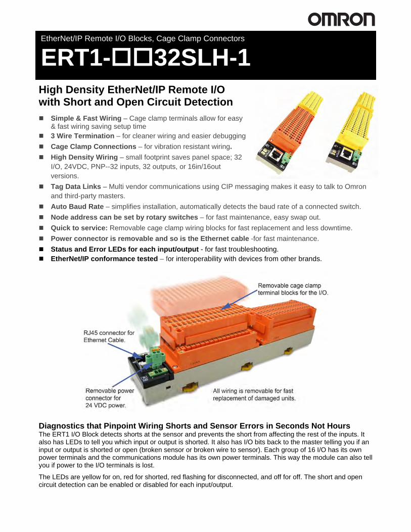
High Density EtherNet/IP Remote I/O with Short and Open Circuit Detection
Simple & Fast Wiring – Cage clamp terminals allow for easy & fast wiring saving setup time
3 Wire Termination – for cleaner wiring and easier debugging Cage Clamp Connections – for vibration resistant wiring. High Density Wiring – small footprint saves panel space; 32
I/O, 24VDC, PNP--32 inputs, 32 outputs, or 16in/16out versions.
Tag Data Links – Multi vendor communications using CIP messaging makes it easy to talk to Omron and third-party masters.
Auto Baud Rate – simplifies installation, automatically detects the baud rate of a connected switch. Node address can be set by rotary switches – for fast maintenance, easy swap out. Quick to service: Removable cage clamp wiring blocks for fast replacement and less downtime. Power connector is removable and so is the Ethernet cable -for fast maintenance. Status and Error LEDs for each input/output - for fast troubleshooting. EtherNet/IP conformance tested – for interoperability with devices from other brands.
Diagnostics that Pinpoint Wiring Shorts and Sensor Errors in Seconds Not Hours The ERT1 I/O Block detects shorts at the sensor and prevents the short from affecting the rest of the inputs. It also has LEDs to tell you which input or output is shorted. It also has I/O bits back to the master telling you if an input or output is shorted or open (broken sensor or broken wire to sensor). Each group of 16 I/O has its own power terminals and the communications module has its own power terminals. This way the module can also tell you if power to the I/O terminals is lost.
The LEDs are yellow for on, red for shorted, red flashing for disconnected, and off for off. The short and open circuit detection can be enabled or disabled for each input/output.
EtherNet/IP Remote I/O Blocks, Cage Clamp Connectors
ERT1- 32SLH-1

2
International Approvals CE, cULus Class I, Division 2, Groups A, B, C and D; IP20 rating for mounting inside an enclosure.
System Configuration
Ordering Information EtherNet/IP Remote I/O Units Inputs Outputs I/O type Output current Input current Model
32 -- PNP -- 6mA at 24VDC max. ERT1-ID32SLH-1 -- 32 PNP 0.5A/point
4.0 A/common -- ERT1-OD32SLH-1
16 16 PNP 0.5A/point 4.0 A/common
6mA at 24VDC max. ERT1-MD32SLH-1
Slave I/O Block Compatibility with Omron Controllers PLC Type ERT1-ID32SLH-1 ERT1-OD32SLH-1 ERT1-MD32SLH-1 CJ2M-CPU3 Yes Yes Yes CJ2H-CPU6 -EIP Yes Yes Yes CJ1, NSJ with CJ1W-EIP21 Yes Yes Yes CS1 with CS1W-EIP21 Yes Yes Yes NJ501-1 00 Yes Yes Yes CP1E No No No CP1L No No No CP1H No No No
Notes: 1) All units require a 24 VDC power supply for power and 24VDC power for each bank of 16 I/O. 2) Minimum current for disconnection detection is 0.2mA. 3) Maximum current for short circuit detection is 50mA/point min. 4) Shorting of one input or output does not affect the rest of the inputs or outputs. 5) Short circuit and disconnection detection can be turned on for each I/O independently.

3
Status Areas
Generic Status Area Generic Status Area which is Tag Set Input_100. The Digital I/O Slave Unit's Generic Status Area contains the following 16 bits. Bit Content Description 00 I/O Power Supply Status Flag 1
OFF: I/O power is ON ON: I/O power is not ON
Turns ON when I/O power is not being supplied to terminal block 1.
01 I/O Power Supply Status Flag 2 OFF: I/O power is ON ON: I/O power is not ON
Turns ON when I/O power is not being supplied to terminal block 2.
02 Reserved --- 03 Reserved --- 04 Power or Load short-circuit detection flag:
OFF: Normal ON: Short-circuit
Turns ON when there is a short in the power supply or load connection to the connected devices, including wiring mistakes and connected device failure.
05 Disconnection flag; OFF: Connected ON: Disconnected
Turns ON when the sensor power supply is not connected or the load is disconnected due to a wiring error, failure in the connected device, etc.
06 Reserved --- 07 Reserved --- 08 EEPROM data error flag:
OFF: Normal ON: Error occurred
Turns ON when there is an error in the EEPROM data.
09 Reserved --- 10 Reserved --- 11 Reserved --- 12 Reserved --- 13 Reserved --- 14 Reserved --- 15 Reserved ---
I/O Status Area I/O Status Area which is Tag Set Input_135. The I/O Status Area for a Digital I/O Slave Unit consists of the following 8 bytes (64 bits). The I/O Status Area indicates the short-circuit and disconnection error status for each terminal.
Byte offset
Data Bit 07 06 05 04 03 02 01 00
0 Power or Load Short-circuit Detection Flags for Terminal Block 1 07 06 05 04 03 02 01 00
1 Power or Load Short-circuit Detection Flags for Terminal Block 1 15 14 13 12 11 10 09 08
2 Power or Load Short-circuit Detection Flags for Terminal Block 2 07 06 05 04 03 02 01 00
3 Power or Load Short-circuit Detection Flags for Terminal Block 2 15 14 13 12 11 10 09 08
4 Disconnection Flags for Terminal Block 1 07 06 05 04 03 02 01 00
5 Disconnection Flags for Terminal Block 1 15 14 13 12 11 10 09 08
6 Disconnection Flags for Terminal Block 2 07 06 05 04 03 02 01 00
7 Disconnection Flags for Terminal Block 2 15 14 13 12 11 10 09 08

4
32 input module - ERT1-ID32SLH-1 There are 32 inputs which are input Tag Set Input_6. 32 output module - ERT1-OD32SLH-1 There are 32 outputs which are input Tag Set Output_36 16 input and 16 output module - ERT1-MD32SLH-1 There are 16 inputs which are input Tag Set Input_5. There are 16 outputs which are output Tag Set Output_35. Note: All of the open and short-circuit status bits are mapped in one of the I/O maps which allows the user to monitor I/O and status bits using polled I/O instead of having to use explicit messages. This makes getting diagnostic data much easier.
Specifications Input Specifications Item Specifications Input points 16 points Internal I/O common PNP ON voltage 15 V DC min. (between each input terminal and 0 V) OFF voltage 5 V DC max. (between each input terminal and 0 V) OFF current 1.0 mA max. Input current 6.0 mA max. at 24 V DC
3.0 mA max. at 17 V DC ON delay time 1.5 ms max. OFF delay time 1.5 ms max. Number of circuits 16 points with one common circuit Isolation method Photocoupler isolation Input indicators LEDs (yellow) Power supply short-circuit Operates at 50 mA/point min. Disconnection detection Operates at 0.2 mA/point max. Connections forms Screw-less clamp terminal blocks (orange)
Output Specifications Item Specification Output points 16 points Internal I/O common PNP Output current 0.5 A/point, 4.0 A/common Residual voltage 1.2 V max. (0.5 A DC, between each output terminal and the V terminal) Leakage current 0.3 mA max. (24 V DC, between each output terminal and V terminal) ON delay 0.5 ms max. OFF delay 1.5 ms max. Number of circuits per common 16 outputs/common Isolation method Photocoupler Output indicators LEDs (yellow) Power supply short-circuit protection
Operates when output current is exceeded.
Disconnection detection Operates at current consumption of 3 mA/point max. (Not detected at 3 mA or less.)
Connection forms Screw-less clamp terminal blocks (yellow)
Common Specifications Item Specifications Current consumption Communications power supply (including internal circuits): 110 mA max. Mounting 35 mm DIN track mounting Weight 485 g max. Standard accessories Connector with lock screws FKMCP1.52STF3.5AUSOO (Phoenix Contact)

5
Component Names and Functions
(1) Rotary Switches These switches are used to set the node address. (2) Ethernet Connector The network communications cable is connected to this connector. (3) Power Supply Connector The communications and Unit power supply is connected to this connector.
Applicable Ferrules Manufacturer Model Applicable wire size Phoenix Contact AI-0.5-10 0.5 mm2 (AWG 20) Nihon Weidmuller H 0.5/16 D 0.5 mm2 (AWG 20)
(4) Communications Indicators: MS and NS These indicators show the Unit communications status and network communications status. (5) and (6) Terminal Blocks 1 and 2 The I/O devices and output power supply are connected to these terminal blocks. (7) and (8) I/O Indicators These indicators show the ON/OFF status of the I/O and the error status of connected devices.

6
Internal Circuits Inputs
Outputs

7
Wiring Inputs
Outputs

8
Common Specifications Dimensions ERT1-ID32SLH-1, ERT1-OD32SLH-1, ERT1-MD32SLH-1
Unit: mm
Indicators I/O Indicators The meanings of the input indicators are given in the following table.
Setting the Node Address The rotary switches are used to set the lower digits of the IP address.
Rotary Switch Settings 00 hex: BOOTP or tool setting enabled (factory setting) 01 to FE hex: Setting on rotary switches is lower 8 bits of IP address. (Default setting of upper 24 bits: 192.168.250.) FF hex: Restores default setting. (To restore the default setting, set the switches to FF hex, cycle the power supply, and then set the switches to 00 hex.)

9
Features Functions Common to All Slave Units This section describes the functions common to all EtherNet/IP Slave Units and the procedures for using them.
Automatic Baud Rate Detection The EtherNet/IP Slave Units are automatically set to the same baud rate as the hub. It is not necessary to set the baud rate separately for any Slave Unit.
The baud rate is set when communications is established with the hub after the power is turned ON. The baud rate setting is stored in memory until the power is turned ON again or until the Master Unit baud rate setting is changed.
Hold/Clear Outputs Output Units can be set to hold or clear outputs when an error occurs.
Procedure Using Network Configurator 1. Turn ON the power to the EtherNet/IP Slave Unit. 2. Double-click the icon of the Slave Unit to set in the Network Edit Device Parameters Window to open the
Configuration Window. (Alternatively, rightclick the icon and select Parameters - Edit from the pop-up menu.)
3. The fault action (holding or clearing an output for a communications error) will be displayed for each output in the Fault Action Setting Group. Select Hold Last State or Clear Data for the terminals and then click the OK Button.
Clear Clears all output data from the Master Unit to 0 when a communications error occurs. Hold Holds all output data from the Master Unit at its current status when a communications error occurs.

10
I/O Power Status Monitor Outputs can be set to be held or cleared when an error occurs in the Output Unit. To check the status, refer to bits 0 and 1 in the Generic Status Area. Input Filter (Input Units Only) An input value is read more than once during a set time interval. The input value can be set to be enabled only when all the read values are the same. This function operates for all input points in one Slave Unit. The following settings are possible: No delay (no filter), or 4, 8, 16, 32, 64, 128, or 256 ms.
OFF-ON Delay When the input data turns ON, the input data is read 4 times at a set time (1/4 of the time setting). The internal input data turns ON only when all four values are ON. The ON timing is delayed by the value of the input time constant.
ON-OFF Delay When the input data turns OFF, the input data is read 5 times at a set interval (1/5 of the OFF response time setting). The internal input data turns OFF only when all values are OFF. The OFF timing is delayed by the value of the OFF response time. This function can also be used to implement an OFF delay. To enable reading pulses shorter than the communications cycle time, set the OFF response time to a value longer than the communications cycle time. (The input may remain ON if the input pulse interval is too short.)

11
Settings Using the Network Configurator 1. Turn ON the power supply to the EtherNet/IP Slave Unit. 2. Double-click the icon of the Slave Unit to set in the Network Configuration Window to open the Edit Device
Parameters Window. (Alternatively, rightclick the icon and select Parameters - Edit from the pop-up menu.) 3. Select an input in the Input Point Group Setting Group and set the Off-On Delay or On-Off delay from the
pull-down menu.
Power Short-circuit Detection (Input) This function monitors the sensor power supply current. If the current is 50 mA or higher per input contact, a power short-circuit is detected. The Slave Unit I/O indicator can be used to check whether a power short-circuit has been detected. When a power short-circuit is detected, a flag in a status area in the Slave Unit turns ON to notify the Master Unit. The notification details can be read using explicit messages. When the cause of the short-circuit is removed, the Slave Unit is automatically reset, and the power output to the connector that had the short-circuit is turned ON again.

12
Load Short-circuit Detection (Output) This function monitors the load current for the output section and detects an load short-circuit if the current per contact (or common) exceeds a specific value. When a load short-circuit is detected, all Unit outputs are turned OFF to prevent damage to the Unit's output circuits. The I/O power for the Unit turns OFF if a short-circuit is detected for even just one of the contacts being used. When a load short-circuit is detected, a flag in a status area in the Slave Unit turns ON to notify the Master Unit. When the cause of the short-circuit is removed, the Slave Unit is automatically reset, and the power output to the connector for which the short-circuit was detected is turned ON again.
Related Products Software CX-One version 4 contains the Network Configurator for EtherNet/IP. CXONE-AL01C-V4 is the part number for a single license copy on CD.
Ethernet Switch Options The following network devices are manufactured by OMRON for EtherNet/IP networks.
Function Number of Ports
Error detection output
Model
Packet priority control (QoS): EtherNet/IP control data priority Failure detection: Broadcast storm, LSI error detection, 10/100Base-TX, Auto-Negotiation
3 None W4S1-03B 5 None W4S1-05B 5 Provided W4S1-05C
Ethernet Cables
Description Connector type Cable length L Model Double-ended EtherCAT Cable with Straight Connectors
RJ45/RJ45 on both ends
0.3 m XS5W-T421-AMD-K0.5 m XS5W-T421-BMD-K1 m XS5W-T421-CMD-K2 m XS5W-T421-DMD-K3 m XS5W-T421-EMD-K5 m XS5W-T421-GMD-K
10 m XS5W-T421-JMD-K15 m XS5W-T421-KMD-K
Manuals Description Media Publication number ERT1 Series EtherNet/IP Slave Units Operation Manual PDF W481-E1-02 XS5 SmartClick Sensor I/O Connectors Data Sheet PDF G016-E1-02
Terms and Conditions of Sale1. Offer; Acceptance. These terms and conditions (these "Terms") are deemed
part of all quotes, agreements, purchase orders, acknowledgments, price lists,catalogs, manuals, brochures and other documents, whether electronic or inwriting, relating to the sale of products or services (collectively, the "Products")by Omron Electronics LLC and its subsidiary companies (“Omron”). Omronobjects to any terms or conditions proposed in Buyer’s purchase order or otherdocuments which are inconsistent with, or in addition to, these Terms.
2. Prices; Payment Terms. All prices stated are current, subject to change with-out notice by Omron. Omron reserves the right to increase or decrease priceson any unshipped portions of outstanding orders. Payments for Products aredue net 30 days unless otherwise stated in the invoice.
3. Discounts. Cash discounts, if any, will apply only on the net amount of invoicessent to Buyer after deducting transportation charges, taxes and duties, and willbe allowed only if (i) the invoice is paid according to Omron’s payment termsand (ii) Buyer has no past due amounts.
4. Interest. Omron, at its option, may charge Buyer 1-1/2% interest per month orthe maximum legal rate, whichever is less, on any balance not paid within thestated terms.
5. Orders. Omron will accept no order less than $200 net billing. 6. Governmental Approvals. Buyer shall be responsible for, and shall bear all
costs involved in, obtaining any government approvals required for the impor-tation or sale of the Products.
7. Taxes. All taxes, duties and other governmental charges (other than generalreal property and income taxes), including any interest or penalties thereon,imposed directly or indirectly on Omron or required to be collected directly orindirectly by Omron for the manufacture, production, sale, delivery, importa-tion, consumption or use of the Products sold hereunder (including customsduties and sales, excise, use, turnover and license taxes) shall be charged toand remitted by Buyer to Omron.
8. Financial. If the financial position of Buyer at any time becomes unsatisfactoryto Omron, Omron reserves the right to stop shipments or require satisfactorysecurity or payment in advance. If Buyer fails to make payment or otherwisecomply with these Terms or any related agreement, Omron may (without liabil-ity and in addition to other remedies) cancel any unshipped portion of Prod-ucts sold hereunder and stop any Products in transit until Buyer pays allamounts, including amounts payable hereunder, whether or not then due,which are owing to it by Buyer. Buyer shall in any event remain liable for allunpaid accounts.
9. Cancellation; Etc. Orders are not subject to rescheduling or cancellationunless Buyer indemnifies Omron against all related costs or expenses.
10. Force Majeure. Omron shall not be liable for any delay or failure in deliveryresulting from causes beyond its control, including earthquakes, fires, floods,strikes or other labor disputes, shortage of labor or materials, accidents tomachinery, acts of sabotage, riots, delay in or lack of transportation or therequirements of any government authority.
11. Shipping; Delivery. Unless otherwise expressly agreed in writing by Omron:a. Shipments shall be by a carrier selected by Omron; Omron will not drop ship
except in “break down” situations.b. Such carrier shall act as the agent of Buyer and delivery to such carrier shall
constitute delivery to Buyer;c. All sales and shipments of Products shall be FOB shipping point (unless oth-
erwise stated in writing by Omron), at which point title and risk of loss shallpass from Omron to Buyer; provided that Omron shall retain a security inter-est in the Products until the full purchase price is paid;
d. Delivery and shipping dates are estimates only; ande. Omron will package Products as it deems proper for protection against nor-
mal handling and extra charges apply to special conditions.12. Claims. Any claim by Buyer against Omron for shortage or damage to the
Products occurring before delivery to the carrier must be presented in writingto Omron within 30 days of receipt of shipment and include the original trans-portation bill signed by the carrier noting that the carrier received the Productsfrom Omron in the condition claimed.
13. Warranties. (a) Exclusive Warranty. Omron’s exclusive warranty is that theProducts will be free from defects in materials and workmanship for a period oftwelve months from the date of sale by Omron (or such other period expressedin writing by Omron). Omron disclaims all other warranties, express or implied.(b) Limitations. OMRON MAKES NO WARRANTY OR REPRESENTATION,EXPRESS OR IMPLIED, ABOUT NON-INFRINGEMENT, MERCHANTABIL-
ITY OR FITNESS FOR A PARTICULAR PURPOSE OF THE PRODUCTS.BUYER ACKNOWLEDGES THAT IT ALONE HAS DETERMINED THAT THEPRODUCTS WILL SUITABLY MEET THE REQUIREMENTS OF THEIRINTENDED USE. Omron further disclaims all warranties and responsibility ofany type for claims or expenses based on infringement by the Products or oth-erwise of any intellectual property right. (c) Buyer Remedy. Omron’s sole obli-gation hereunder shall be, at Omron’s election, to (i) replace (in the formoriginally shipped with Buyer responsible for labor charges for removal orreplacement thereof) the non-complying Product, (ii) repair the non-complyingProduct, or (iii) repay or credit Buyer an amount equal to the purchase price ofthe non-complying Product; provided that in no event shall Omron be responsi-ble for warranty, repair, indemnity or any other claims or expenses regardingthe Products unless Omron’s analysis confirms that the Products were prop-erly handled, stored, installed and maintained and not subject to contamina-tion, abuse, misuse or inappropriate modification. Return of any Products byBuyer must be approved in writing by Omron before shipment. Omron Compa-nies shall not be liable for the suitability or unsuitability or the results from theuse of Products in combination with any electrical or electronic components,circuits, system assemblies or any other materials or substances or environ-ments. Any advice, recommendations or information given orally or in writing,are not to be construed as an amendment or addition to the above warranty.See http://www.omron247.com or contact your Omron representative for pub-lished information.
14. Limitation on Liability; Etc. OMRON COMPANIES SHALL NOT BE LIABLEFOR SPECIAL, INDIRECT, INCIDENTAL, OR CONSEQUENTIAL DAMAGES,LOSS OF PROFITS OR PRODUCTION OR COMMERCIAL LOSS IN ANYWAY CONNECTED WITH THE PRODUCTS, WHETHER SUCH CLAIM ISBASED IN CONTRACT, WARRANTY, NEGLIGENCE OR STRICT LIABILITY.Further, in no event shall liability of Omron Companies exceed the individualprice of the Product on which liability is asserted.
15. Indemnities. Buyer shall indemnify and hold harmless Omron Companies andtheir employees from and against all liabilities, losses, claims, costs andexpenses (including attorney's fees and expenses) related to any claim, inves-tigation, litigation or proceeding (whether or not Omron is a party) which arisesor is alleged to arise from Buyer's acts or omissions under these Terms or inany way with respect to the Products. Without limiting the foregoing, Buyer (atits own expense) shall indemnify and hold harmless Omron and defend or set-tle any action brought against such Companies to the extent based on a claimthat any Product made to Buyer specifications infringed intellectual propertyrights of another party.
16. Property; Confidentiality. Any intellectual property in the Products is the exclu-sive property of Omron Companies and Buyer shall not attempt to duplicate itin any way without the written permission of Omron. Notwithstanding anycharges to Buyer for engineering or tooling, all engineering and tooling shallremain the exclusive property of Omron. All information and materials suppliedby Omron to Buyer relating to the Products are confidential and proprietary,and Buyer shall limit distribution thereof to its trusted employees and strictlyprevent disclosure to any third party.
17. Export Controls. Buyer shall comply with all applicable laws, regulations andlicenses regarding (i) export of products or information; (iii) sale of products to“forbidden” or other proscribed persons; and (ii) disclosure to non-citizens ofregulated technology or information.
18. Miscellaneous. (a) Waiver. No failure or delay by Omron in exercising any rightand no course of dealing between Buyer and Omron shall operate as a waiverof rights by Omron. (b) Assignment. Buyer may not assign its rights hereunderwithout Omron's written consent. (c) Law. These Terms are governed by thelaw of the jurisdiction of the home office of the Omron company from whichBuyer is purchasing the Products (without regard to conflict of law princi-ples). (d) Amendment. These Terms constitute the entire agreement betweenBuyer and Omron relating to the Products, and no provision may be changedor waived unless in writing signed by the parties. (e) Severability. If any provi-sion hereof is rendered ineffective or invalid, such provision shall not invalidateany other provision. (f) Setoff. Buyer shall have no right to set off any amountsagainst the amount owing in respect of this invoice. (g) Definitions. As usedherein, “including” means “including without limitation”; and “Omron Compa-nies” (or similar words) mean Omron Corporation and any direct or indirectsubsidiary or affiliate thereof.
Certain Precautions on Specifications and Use1. Suitability of Use. Omron Companies shall not be responsible for conformity
with any standards, codes or regulations which apply to the combination of theProduct in the Buyer’s application or use of the Product. At Buyer’s request,Omron will provide applicable third party certification documents identifyingratings and limitations of use which apply to the Product. This information byitself is not sufficient for a complete determination of the suitability of the Prod-uct in combination with the end product, machine, system, or other applicationor use. Buyer shall be solely responsible for determining appropriateness ofthe particular Product with respect to Buyer’s application, product or system.Buyer shall take application responsibility in all cases but the following is anon-exhaustive list of applications for which particular attention must be given:(i) Outdoor use, uses involving potential chemical contamination or electricalinterference, or conditions or uses not described in this document.(ii) Use in consumer products or any use in significant quantities. (iii) Energy control systems, combustion systems, railroad systems, aviationsystems, medical equipment, amusement machines, vehicles, safety equip-ment, and installations subject to separate industry or government regulations. (iv) Systems, machines and equipment that could present a risk to life or prop-erty. Please know and observe all prohibitions of use applicable to this Prod-uct. NEVER USE THE PRODUCT FOR AN APPLICATION INVOLVING SERIOUSRISK TO LIFE OR PROPERTY OR IN LARGE QUANTITIES WITHOUTENSURING THAT THE SYSTEM AS A WHOLE HAS BEEN DESIGNED TO
ADDRESS THE RISKS, AND THAT THE OMRON’S PRODUCT IS PROP-ERLY RATED AND INSTALLED FOR THE INTENDED USE WITHIN THEOVERALL EQUIPMENT OR SYSTEM.
2. Programmable Products. Omron Companies shall not be responsible for theuser’s programming of a programmable Product, or any consequence thereof.
3. Performance Data. Data presented in Omron Company websites, catalogsand other materials is provided as a guide for the user in determining suitabil-ity and does not constitute a warranty. It may represent the result of Omron’stest conditions, and the user must correlate it to actual application require-ments. Actual performance is subject to the Omron’s Warranty and Limitationsof Liability.
4. Change in Specifications. Product specifications and accessories may bechanged at any time based on improvements and other reasons. It is our prac-tice to change part numbers when published ratings or features are changed,or when significant construction changes are made. However, some specifica-tions of the Product may be changed without any notice. When in doubt, spe-cial part numbers may be assigned to fix or establish key specifications foryour application. Please consult with your Omron’s representative at any timeto confirm actual specifications of purchased Product.
5. Errors and Omissions. Information presented by Omron Companies has beenchecked and is believed to be accurate; however, no responsibility is assumedfor clerical, typographical or proofreading errors or omissions.

Printed on recycled paper.
R34I-E-01 08/11 Note: Specifications are subject to change. © 2011 Omron Electronics LLC Printed in U.S.A.
OMRON CANADA, INC. • HEAD OFFICEToronto, ON, Canada • 416.286.6465 • 866.986.6766 • www.omron247.com
OMRON ELECTRONICS DE MEXICO • HEAD OFFICEMéxico DF • 52.55.59.01.43.00 • 001.800.556.6766 • [email protected]
OMRON ELECTRONICS DE MEXICO • SALES OFFICEApodaca, N.L. • 52.81.11.56.99.20 • 001.800.556.6766 • [email protected]
OMRON ELETRÔNICA DO BRASIL LTDA • HEAD OFFICESão Paulo, SP, Brasil • 55.11.2101.6300 • www.omron.com.br
OMRON ARGENTINA • SALES OFFICECono Sur • 54.11.4783.5300
OMRON CHILE • SALES OFFICESantiago • 56.9.9917.3920
OTHER OMRON LATIN AMERICA SALES54.11.4783.5300
Automation Systems• Programmable logic controllers (PLC) • Human machine interfaces (HMI) • Remote I/O• Industrial PC’s • Software
Motion & Drives • Motion controllers • Servo systems • AC drives
Control Components • Temperature controllers • Power supplies • Timers • Counters • Programmable relays • Digital panel indicators • Electromechanical relays • Monitoring products • Solid-state relays • Limit switches • Pushbutton switches • Low voltage switch gear
Sensing & Safety • Photoelectric sensors • Inductive sensors • Capacitive & pressure sensors • Cable connectors • Displacement & width-measuring sensors • Vision systems • Safety networks • Safety sensors • Safety units/relay units • Safety door/guard lock switches
Authorized Distributor:
OMRON INDUSTRIAL AUTOMATION • THE AMERICAS HEADQUARTERS • Schaumburg, IL USA • 847.843.7900 • 800.556.6766 • www.omron247.com
OMRON EUROpE B.V. • Wegalaan 67-69, NL-2132 JD, Hoofddorp, The Netherlands. • Tel: +31 (0) 23 568 13 00 • Fax: +31 (0) 23 568 13 88 • www.industrial.omron.eu