
Wonderware DAServer for Omron FINS Ethernet User’s · PDF fileOmron CS1, CJ1, CV, C...
120
Wonderware DAServer for Omron FINS Ethernet User’s Guide Invensys Systems, Inc. Revision B Last Revision: 10/26/07
Transcript of Wonderware DAServer for Omron FINS Ethernet User’s · PDF fileOmron CS1, CJ1, CV, C...

Wonderware DAServer for Omron
FINS Ethernet User’s Guide
Invensys Systems, Inc.
Revision B
Last Revision: 10/26/07

Copyright© 2007 Invensys Systems, Inc. All Rights Reserved.
All rights reserved. No part of this documentation shall be reproduced, stored in a retrieval system, or transmitted by any means, electronic, mechanical, photocopying, recording, or otherwise, without the prior written permission of Invensys Systems, Inc. No copyright or patent liability is assumed with respect to the use of the information contained herein. Although every precaution has been taken in the preparation of this documentation, the publisher and the author assume no responsibility for errors or omissions. Neither is any liability assumed for damages resulting from the use of the information contained herein.
The information in this documentation is subject to change without notice and does not represent a commitment on the part of Invensys Systems, Inc. The software described in this documentation is furnished under a license or nondisclosure agreement. This software may be used or copied only in accordance with the terms of these agreements.
Invensys Systems, Inc.26561 Rancho Parkway SouthLake Forest, CA 92630 U.S.A.(949) 727-3200
http://www.wonderware.com
For comments or suggestions about the product documentation, send an e-mail message to [email protected].
TrademarksAll terms mentioned in this documentation that are known to be trademarks or service marks have been appropriately capitalized. Invensys Systems, Inc. cannot attest to the accuracy of this information. Use of a term in this documentation should not be regarded as affecting the validity of any trademark or service mark.
Alarm Logger, ActiveFactory, ArchestrA, Avantis, DBDump, DBLoad, DT Analyst, FactoryFocus, FactoryOffice, FactorySuite, FactorySuite A2, InBatch, InControl, IndustrialRAD, IndustrialSQL Server, InTouch, MaintenanceSuite, MuniSuite, QI Analyst, SCADAlarm, SCADASuite, SuiteLink, SuiteVoyager, WindowMaker, WindowViewer, Wonderware, and Wonderware Logger are trademarks of Invensys plc, its subsidiaries and affiliates. All other brands may be trademarks of their respective owners.
3
Wonderware DAServer for Omron FINS Ethernet User’s Guide
Contents
Welcome........................................... 7Documentation Conventions...............................................7Technical Support................................................................8
Chapter 1 Getting Started .................................... 9Before You Begin ...............................................................10
Supported Client Protocols ............................................10Supported Device Protocols ...........................................11Supported Devices ..........................................................11Supported Topologies......................................................11Windows Firewall Considerations.................................12
Checklist for Setting up a DAServer ................................14Finding Your DAServer in the SMC.................................15
Chapter 2 Managing Channels .............................. 17Adding a Channel..............................................................18Renaming a Channel.........................................................18Setting Channel Parameters ............................................18
Selecting the Adapter.....................................................19Setting the Communciations Port .................................19Setting the Write/Read Duty Cycle ...............................20
Deleting a Channel............................................................21
4 Contents
Wonderware DAServer for Omron FINS Ethernet User’s Guide
Chapter 3 Managing Devices ................................23Adding a Device.................................................................23Renaming a Device............................................................24Setting the General Parameters.......................................24
Assigning a PLC Model to the Device ...........................24Setting the ID Parameter ..............................................25
Setting the Protocol Parameters ......................................26Setting the Communication Timeouts ..........................26Setting the Request Size ................................................27
Setting the FINS Network Configuration........................28Setting Single and Multiple Network Levels................29Matching Device and PLC Addresses ...........................29
Deleting a Device...............................................................30
Chapter 4 Managing Device Groups ........................31Adding a Device Group .....................................................31Renaming a Device Group ................................................32Setting Device Group Data ...............................................33Deleting a Device Group ...................................................34
Chapter 5 Managing Device Items..........................35Creating Aliases for Item References...............................36Renaming a Device Item...................................................37Deleting a Device Item......................................................37Setting the Item Reference ...............................................38Exporting and Importing CSV Files.................................38Clearing All Device Item Names ......................................39
Chapter 6 Managing Your DAServer ........................41Configuring the DAServer as Service ..............................42Configuring the DAServer as Not a Service ....................42Archiving Configuration Sets ...........................................42Activating/Deactivating the DAServer ............................44In-Proc/Out-of-Proc ...........................................................45Hot Configuration .............................................................45Demo Mode ........................................................................46
Chapter 7 Accessing the Data in Your DAServer ........47Accessing Data Using OPC...............................................48

Contents 5
Wonderware DAServer for Omron FINS Ethernet User’s Guide
Accessing Data Using DDE/SuiteLink.............................48
Chapter 8 Item Reference Descriptions.................. 49Standard System Items.....................................................49
Global System Item........................................................50Device-Group-Specific System Items ............................51
Device-Specific System Items ...........................................55Supported Data Types.......................................................58Format and Syntax............................................................59
Unsigned/Signed Format ...............................................59BCD Format....................................................................60Long Format (Signed/BCD) ...........................................60Floating Point Format (IEEE) .......................................60ASCII Strings Format ....................................................61Alternate ASCII String Format.....................................62Bit Access ........................................................................63Array Access ...................................................................63Using 32-bit Values ........................................................63
Address Descriptions.........................................................64C200 Address Descriptions ............................................64CV500 Address Descriptions .........................................70CV1000 and CV2000 Address Descriptions ..................74CVM1-CPU01 Address Descriptions .............................80CVM1-CPU11 Address Descriptions .............................84CVM1-CPU21 Address Descriptions .............................88CS1 Address Descriptions..............................................95CJ1 Address Descriptions ............................................101
Chapter 9 Troubleshooting ................................107Troubleshooting with Windows Tools .............................107Troubleshooting with the DAServer Manager...............108Finding Version Information ..........................................108Using the Wonderware Log Viewer ................................108
Basic Log Flags.............................................................109DAServer Log Flags .....................................................110DAServer-Device Interface Log Flags ......................... 111
Error Message Descriptions............................................112
Index .............................................117

6 Contents
Wonderware DAServer for Omron FINS Ethernet User’s Guide
7
Wonderware DAServer for Omron FINS Ethernet User’s Guide
Welcome
The Wonderware DAServer for Omron Fins Ethernet is a Microsoft Windows application that allows client applications access to the SYSMAC C/CV/CS1/CJ1-Series Programmable Logic Controllers (PLCs).
Documentation ConventionsThis documentation uses the following conventions:
Convention Used for
Initial Capitals Paths and filenames.
Bold Menus, commands, dialog box names, and dialog box options.
Monospace Code samples and display text.

8 Welcome
Wonderware DAServer for Omron FINS Ethernet User’s Guide
Technical SupportWonderware Technical Support offers a variety of support options to answer any questions on Wonderware products and their implementation.
Before you contact Technical Support, refer to the relevant section(s) in this documentation for a possible solution to any problem you have. If you need to contact technical support for help, have the following information ready:
• The type and version of the operating system you are using. For example, Microsoft Windows XP, SP1.
• Details of how to recreate the problem.
• The exact wording of the error messages you saw.
• Any relevant output listing from the Log Viewer or any other diagnostic applications.
• Details of what you did to try to solve the problem(s) and your results.
If known, the Wonderware Technical Support case number assigned to your problem, if this is an ongoing problem.
9
Wonderware DAServer for Omron FINS Ethernet User’s Guide
Chapter 1
Getting Started
The DAServer is one component of a software system that connects your software application with information on the factory floor.
This DAServer documentation covers only the information you need to configure and run the DAServer component. See the documentation that comes with the related components for details on their operation. You can find installation instructions in a help file on the distribution CD.
You use the DAServer Manager to configure, activate, and troubleshoot the DAServer. The DAServer Manager is located in the System Management Console (SMC). For more information, see Finding Your DAServer in the SMC on page 15.
This documentation describes some of the features of the DAServer Manager. See the DAServer Manager User’s Guide to find more information on:
• Global parameters
• Configuration sets
• Time zone features
• Icon definitions
• Activation/deactivation
• Configuring as a service
• Importing/exporting device items
• Standard diagnostics

10 Chapter 1 Getting Started
Wonderware DAServer for Omron FINS Ethernet User’s Guide
You can troubleshoot problems with the DAServer using the ArchestrA Log Viewer, a snap-in to the SMC. See the Log Viewer help file to find information on:
• Viewing error messages.
• Determining which messages are shown.
• Bookmarking error messages.
You may also be able to troubleshoot problems using your client application, such as the Wonderware InTouch HMI software. The client application can use system device items to determine the status of nodes and the values of some parameters. For more information on system items, see Standard System Items on page 49.
Before You BeginBefore configuring the DAServer, verify the following items:
• A PC is set up with the necessary network cards, and connected to the necessary networks.
• The Windows administration account is created or identified.
• The DAServer and any other Wonderware software such as the DAServer Manager is installed with the proper licenses. For more information, see the License Utility documentation on the distribution CD.
• The client software is installed.
• The device(s) is/are connected (networked) and, if necessary, programmed.
Before configuring the DAServer, you should know:
• The device network configuration and addresses.
• Which data items are needed for the client application.
• The device name/topic name/group name.
• The desired update intervals.
Supported Client ProtocolsClient applications connect to the DAServer using OPC and DDE/SuiteLink. For more information, see the Protocols guide that is included with the distribution CD.

Before You Begin 11
Wonderware DAServer for Omron FINS Ethernet User’s Guide
Supported Device ProtocolsThe DAServer connects to Omron PLCs on a FINS network using UDP/IP.
Supported DevicesYou can use the following Omron devices with this DAServer:
• C200
• CV500
• CV1000
• CV2000
• CVM1-CPU01
• CVM1-CPU11
• CVM1-CPU21
• CS1
• CJ1
Supported TopologiesThis DAServer communicates with FINS compatible devices on an Ethernet network. If a device is a destination node, it processes the FINS command. If a device is not the destination node, it relays the message on to the destination node.
Both the routing PLC(s) and target PLC must support FINS.

12 Chapter 1 Getting Started
Wonderware DAServer for Omron FINS Ethernet User’s Guide
FINS allows up to three network levels. A direct connection between a computer and a PLC through Host Link is not considered a network level.
Windows Firewall ConsiderationsIf the DAServer runs on a computer with a firewall enabled, a list of application names or port numbers must be put in the firewall exception list so the DAServer can function correctly.
By default, the DAServer installation program makes the required entries in the firewall exception list. If you do not want the installation program to make entries in the firewall exception list, you must add the entries manually. For information on how make entries in the firewall exception list, see your firewall or Windows security documentation.
You must ensure the following applications are in the firewall exception list. The applications can be added automatically during installation, or you can add them manually on the computer running the DAServer:
• DASOMFINSEnet.exe
• aaLogger.exe
• DASAgent.exe
• dllhost.exe
• mmc.exe
• OPCEnum.exe
PC
Ethernet
Omron CS1, CJ1, CV, C Series PLC with Ethernet Adapter
Omron CS1, CJ1, CV, C Series PLC with Ethernet Adapter and Controller Link Adapter ( acts as bridge )
Omron CS1, CJ1, CV, C Series PLC with
Controller Link Adapter
Omron CS1, CJ1, CV, C Series PLC with Ethernet Adapter
Omron CS1, CJ1, CV, C Series PLC with
Controller Link Adapter
Controller Link
Before You Begin 13
Wonderware DAServer for Omron FINS Ethernet User’s Guide
• Slssvc.exe
You must ensure the following port numbers are in the firewall exception list. The port numbers can be added automatically during installation, or you can add them manually on the computer running the DAServer:
• 5413 - TCP port for slssvc.exe
• 445 - TCP port for file and printer sharing
• 135 - TCP port for DCOM
• 9600 a UDP port for DASOMFINSEnet
• UDP ports configured in the PLC for use with this DAServer, other than the standard port 9600.
Put the following applications in the firewall exception list on the computer where the DAServer Manager is installed:
• aaLogger.exe
• dllhost.exe
• mmc.exe
Put the following port numbers in the firewall exception list on the computer where the DAServer Manager is installed:
• 445 - TCP port for file and printer sharing
• 135 - TCP port for DCOM
Un-installing the DAServer does not remove the firewall exception list entries. You must delete the firewall exception list entries manually. For more information on how to do this, see your firewall or Windows security documentation.

14 Chapter 1 Getting Started
Wonderware DAServer for Omron FINS Ethernet User’s Guide
Checklist for Setting up a DAServerIf you are setting up a DAServer for the first time, perform the following tasks in the order listed:
1 Review the items described in Before You Begin on page 10.
2 Locate the DAServer in the System Management Console (SMC). See Finding Your DAServer in the SMC on page 15.
3 Configure the global parameters. See the DAServer Manager User’s Guide.
4 Add a channel. See Adding a Channel on page 18.
5 Set the channel parameters. See Setting Channel Parameters on page 18.
6 Add a device. See Adding a Device on page 23.
7 Set the device communication parameters. See Setting the General Parameters on page 24.
8 Add one or more device groups. See Adding a Device Group on page 31.
9 Add device items. See Managing Device Items on page 35.
10 Activate the DAServer. See Activating/Deactivating the DAServer on page 44.
11 Access data from the client, including specifying device item references. See Accessing the Data in Your DAServer on page 47 and Setting the Item Reference on page 38.
12 Troubleshoot any problems. See Troubleshooting on page 107.

Finding Your DAServer in the SMC 15
Wonderware DAServer for Omron FINS Ethernet User’s Guide
Finding Your DAServer in the SMCEach DAServer is identified by a unique name. The name for the Wonderware DAServer for Omron Fins Ethernet is ArchestrA.DASOMFINSEnet.1. On the computer where the DAServer is installed, it can be found in the local node of the default group of the DAServer Manager.
You do not need to install the DAServer Manager on the same computer as the DAServer. When you access the DAServer remotely, you will not find the DAServer node under the local node. You must locate and identify the DAServer on a computer in one of the node groups.
To find the DAServer
1 On the Start menu, click Programs. Navigate to the Wonderware folder that contains the System Management Console and then click System Management Console.
2 In the System Management Console, expand DAServer Manager.
3 Locate the group with the node ArchestrA.DASOMFINSEnet.1

16 Chapter 1 Getting Started
Wonderware DAServer for Omron FINS Ethernet User’s Guide

17
Wonderware DAServer for Omron FINS Ethernet User’s Guide
Chapter 2
Managing Channels
Channels are the communications link between the DAServer and devices. You must create a channel node before you can add device nodes. You can create up to 100 channels.
Before you add a channel, you need to organize and define the topology of the devices being connected.
When you add a channel, the DAServer gives the channel a default name. You may change this name to a name that represents how the network is organized. Channel names cannot have spaces.
A channel has three parameters:
• The adapter card the channel uses to communicate with devices
• The communications port
• The write/read duty cycle

18 Chapter 2 Managing Channels
Wonderware DAServer for Omron FINS Ethernet User’s Guide
Adding a ChannelThe first step in specifying the network between the DAServer and a device is to add a channel. After you add a channel to the hierarchy, you can add device nodes.
To add a channel
1 In the DAServer Manager, navigate to the Configuration node.
a Expand DAServer Manager, expand the node group, and then expand Local or the remote computer name.
b Expand the DAServer.
2 Right- click Configuration and click Add Channel Object.
The console tree shows a new node with a default channel name selected.
3 Type a new name and then press Enter.
Renaming a ChannelChanging the channel name prevents clients from registering data using the old name. Data for existing queries is set to bad quality. Try not to make changes to parameters like the channel name after you develop a large client application.
To change an existing channel name
1 In the DAServer Manager, navigate to the channel.
a Expand DAServer Manager, expand the node group, and then expand Local or the remote computer name.
b Expand the DAServer and then expand Configuration.
2 Right-click the channel and click Rename.
3 Type the new name and press Enter.
Setting Channel ParametersChannel parameters include the adapter, the communications port, and the write/read duty cycle.

Setting Channel Parameters 19
Wonderware DAServer for Omron FINS Ethernet User’s Guide
Selecting the AdapterIf devices are connected to multiple adapters, specify which adapter a channel uses, because devices are tied to channels. Use Default if you have a single active network connection. If you have multiple network cards, select the card connected to the subnetwork on which the PLCs are located. You can assign an adapter to multiple channels. However, a channel can have only one adapter.
Spreading your devices over several channels can improve DAServer performance. The performance benefit depends on the message traffic on your network.
The recommended configuration is one Device (PLC) per channel.
The network adapter specifies the Network Interface Card (NIC) the DAServer should use when accessing devices on the channel.
You can change the adapter parameter when the DAServer is active. Changing the adapter parameter when the DAServer is active can disrupt network communications.
To select the adapter
1 In the DAServer Manager, navigate to the channel.
a Expand DAServer Manager, expand the node group, and then expand Local or the remote computer name.
b Expand the DAServer and then expand Configuration.
2 Select the channel. The right pane shows the channel parameters.
3 In the Adapter list, click the appropriate adapter.
4 Click the Save icon.
Setting the Communciations PortThe FINS network protocol requires that all devices on an Ethernet network use the same port number to send and receive data. Valid port numbers range from 1 to 65535, with a default of 9600.
For best communication performance, create multiple channels, and assign each channel a unique port number.
Note The same FINS/UDP port must be configured in the PLC connected to this channel.
For example:
• Channel1.device1 communicates on Port 9601

20 Chapter 2 Managing Channels
Wonderware DAServer for Omron FINS Ethernet User’s Guide
• Channel2.device2 communicates on Port 9602
Note Configure all devices ( PLCs) connected to a channel with the same FINS/UDP Port as the channel.
Multihoming the computer running the DASOMFINSEthernet server can enable communication with multiple PLCs configured on different channels using the same UDP port (for example default 9600).
To set the port number
1 In the DAServer Manager, navigate to the channel.
a Expand DAServer Manager, expand the node group, and then expand Local or the remote computer name.
b Expand the DAServer and then expand Configuration.
2 Select the channel. The right pane shows the channel parameters.
3 In the Port box, enter a port number.
4 Click the Save icon.
Setting the Write/Read Duty CycleThe duty cycle allows you to control the ratio of write operations to read operations. The ratio is always based on one read for every 1 to 10 writes. The default duty cycle is 10. This means 10 writes occur for each read operation.
If your application is doing a large number of continuous writes and you need to ensure that reads are processed in a timely fashion, you may want to reduce the duty cycle. If you set the duty cycle to 1, a single read operation occurs for every write operation. If there are no write operations to perform, reads are processed as needed.
This write/read duty cycle overrides the transaction to subscription ratio global parameter.
To set the write/read duty cycle
1 In the DAServer Manager, navigate to the channel.
a Expand DAServer Manager, expand the node group, and then expand Local or the remote computer name.
b Expand the DAServer and then expand Configuration.
2 Select the channel. The right pane shows the channel parameters.
3 In the Write/Read Duty Cycle box, type or select a number.
4 Click the Save icon.

Deleting a Channel 21
Wonderware DAServer for Omron FINS Ethernet User’s Guide
Deleting a ChannelIf your computer hardware or the network connection between the computer and devices changes, you need to delete a channel.
When you delete a channel, all nodes below the channel are also deleted. If a client application requests new data from a deleted channel or from a node on a deleted channel, the request is rejected. Data for existing queries is set to bad quality.
To delete a channel
1 In the DAServer Manager, navigate to the channel.
a Expand DAServer Manager, expand the node group, and then expand Local or the remote computer name.
b Expand the DAServer and then expand Configuration.
2 Right-click the channel and click Delete.
3 Read the warning and then click Yes. The channel node and all nodes (devices) below it in the hierarchy are deleted.

22 Chapter 2 Managing Channels
Wonderware DAServer for Omron FINS Ethernet User’s Guide

23
Wonderware DAServer for Omron FINS Ethernet User’s Guide
Chapter 3
Managing Devices
A device communicates with a DAServer and may connect to other devices or I/O points. You set the communication parameters the DAServer uses to communicate with a device.
Adding a DeviceYou must add a device to the hierarchy before creating device items. A device name cannot contain spaces.
To add a device
1 In the DAServer Manager, navigate to the channel node.
a Expand DAServer Manager, expand the node group, and then expand Local or the remote computer name.
b Expand the DAServer and then expand Configuration.
2 Right-click the channel node and click Add Device Object. The console tree shows a new node with a default device name selected.
3 Type a name and press Enter.

24 Chapter 3 Managing Devices
Wonderware DAServer for Omron FINS Ethernet User’s Guide
Renaming a DeviceYou can change the device name while the DAServer is active. After the device name is changed, client applications using the old name cannot register data with the DAServer. Data for existing queries is set to bad quality. Try not to make changes to the device name after you develop a large client application.
The device name cannot contain spaces.
To change an existing device name
1 In the DAServer Manager, navigate to the device.
a Expand DAServer Manager, expand the node group, and then expand Local or the remote computer name.
b Expand the DAServer, expand Configuration, and then expand the channel.
2 Right-click the device whose name you want to change and then click Rename.
3 Type a name and press Enter.
Setting the General ParametersYou can set the general parameters by selecting the Controller model, setting the ID Parameter, and enabling data collection.
Assigning a PLC Model to the DeviceYou can only change the model selection if there are currently no client applications connected to the device.
To assign a PLC model to a device
1 In the DAServer Manager, navigate to the device.
a Expand DAServer Manager, expand the node group, and then expand Local or the remote computer name.
b Expand the DAServer, expand Configuration, and then expand the channel.
2 Select the device.
3 In the right pane, click the Parameters tab. This is shown with the device name followed by the word “Parameters.”

Setting the General Parameters 25
Wonderware DAServer for Omron FINS Ethernet User’s Guide
4 In the Model list, select the model.
5 Click the Save icon.
Setting the ID ParameterYou specify the IP address of the device if it is on the same Ethernet network as the computer running the DAServer. Otherwise, you specify the IP address of the relay device, which must be on the same Ethernet network as the computer running the DAServer.
For more information, see your OMRON FINS documentation.
To set the ID
1 In the DAServer navigate to the device.
a Expand DAServer Manager, expand the node group, and then expand Local or the remote computer name.
b Expand the DAServer, expand Configuration, and then expand the channel.
2 Select the device.
3 In the right pane, click the Parameters tab. The tab appears with the device name followed by the word “Parameters.”
4 In the ID box, type the network address.
5 Click the Save icon.

26 Chapter 3 Managing Devices
Wonderware DAServer for Omron FINS Ethernet User’s Guide
Setting the Protocol ParametersThe device protocol parameters include the communications timeouts and the request size parameter.
Setting the Communication TimeoutsYou can set three communication timeouts: connect timeout, reply timeout, and fail after.
• The connect timeout is the time that the DAServer waits for a connection to be made with a device. Depending on the network load, the connect time varies with each connection attempt. The default setting is 3 seconds. The valid range is 1 to 60 seconds. For heavily loaded or slow networks, set the connection time out to a larger value.
• The reply timeout is the time the DAServer waits on a response from the device before giving up and going on to the next request. Longer timeouts only affect performance if a device is not responding.
• The fail after parameter determines how many times the DAServer sends a communications request before the request fails and the device is in error. The valid range is 1 to 10 retries. The default is 3 retries.
To set the communication time out values
1 In the DAServer Manager, navigate to the device.
a Expand DAServer Manager, expand the node group, and then expand Local or the remote computer name.
b Expand the DAServer, expand Configuration, and then expand the channel.
2 Select the device.
3 Click the Parameters tab. The tab appears with the device name followed by the word “Parameters.”
4 In the Protocol area, type or select values for the Connect timeout, Reply timeout and Fail after boxes.
5 Click the Save icon.

Setting the Protocol Parameters 27
Wonderware DAServer for Omron FINS Ethernet User’s Guide
Setting the Request SizeYou can set the number of bytes that are returned from a device at a single time. If the DAServer is reading data from a large number of contiguous addresses, it is probably advantageous to use a large request size.
You can configure the request size as: 32, 64, 128, 256, or 512 bytes. The default value is 512 bytes.
To set the request size
1 In the DAServer Manager navigate to the device.
a Expand DAServer Manager, expand the node group, and then expand Local or the remote computer name.
b Expand the DAServer, expand Configuration, and then expand the channel.
2 Select the device.
3 In the right pane select the Parameters tab. The tab appears with the device name followed by the word “Parameters.”
4 In the Request size list, enter or select a number.
5 Click the Save Icon.

28 Chapter 3 Managing Devices
Wonderware DAServer for Omron FINS Ethernet User’s Guide
Setting the FINS Network ConfigurationThe FINS network configuration includes six parameters of of FINS message headers. These parameters are:
• Source network address number. This the network address number of the source device, the computer running the DAServer. This is sometimes called SNA in Omron FINS documentation. Valid numbers range from 0 to 127.
• Source node number. This the node number of the computer running the DAServer. This is sometimes called SA1 in Omron FINS documentation. Valid numbers range from 0 to 254.
The number configured on the Device Configuration face plate must be unique and should be the host part of the PC’s IP address. If two DAServers access the same PLC, the source node number must also be unique.
If the destination PLC is configured to use automatic address generation, this number must be the host number portion of the host computer's IP address. For example, if the host computer has an IP of 111.222.333.123, and the subnet mask is 255.255.255.000, the source node number is 123.
If the destination PLC is configured to use an address table, the table must have an entry for the host computer's IP. The node number in this table entry must match the source node number entered here.
Tip For network card redundancy when using a PC with Dual NICs, configure the PLC for Auto-Dynamic Address Table generation, and configure the DAServer Adapter as Default. In case the primary network connection fails, the PLC can resume communication with the DAServer via the second network connectionFor more information, see Selecting the Adapter on page 19.
• Source unit number. This the unit number of the computer running the DAServer. This is sometimes called SA2 in OMRON FINS documentation. The DAServer always sets this parameter to zero.
• Destination network address number. This the network address number of the destination device. This is sometimes called DNA in Omron FINS documentation. Valid numbers range from 0 to 127.
• Destination Node number. This the node number of the destination device. This is sometimes called DA1 in Omron FINS documentation. Valid numbers range from 0 to 254.

Setting the FINS Network Configuration 29
Wonderware DAServer for Omron FINS Ethernet User’s Guide
• Destination Unit number. This the unit number of the destination device. This is sometimes called DA2 in OMRON FINS documentation. Valid numbers range from 0 to 255. The default is zero.
Setting Single and Multiple Network LevelsThe default value for the network parameter in each case is zero. Zero represents the local network.
Using zero is convenient if there is only one network level. When you use multiple network levels, you must specify the actual network number (1 - 127) to avoid routing ambiguities.
Matching Device and PLC AddressesPay particular attention to the FINS network and node numbers configured for each device and the IP address calculation method used by the target PLCs. Inconsistent values result in communications problems. For more information, see the OMRON FINS documentation.
To set the FINS network parameters
1 In the DAServer Manager, navigate to the device.
a Expand DAServer Manager, expand the node group, and then expand Local or the remote computer name.
b Expand the DAServer, expand Configuration, and then expand the channel.
2 Select the device.
3 In the right pane select the Parameters tab. The tab appears with the device name followed by the word “Parameters.”
4 In the FINS Network Configuration area, enter a number in each field.
5 Click the Save icon.
30 Chapter 3 Managing Devices
Wonderware DAServer for Omron FINS Ethernet User’s Guide
Deleting a DeviceDeleting a device removes the node and all device group and device item information. Deleting a device is not reversible. If you make a mistake, you must re-enter the device information.
New requests for data that use the deleted device name are rejected. Data for existing queries is set to bad quality.
To delete a device
1 In the DAServer Manager, navigate to the device.
a Expand DAServer Manager, expand the node group, and then expand Local or the remote computer name.
b Expand the DAServer, expand Configuration, and then expand the channel.
2 Right-click the device and then click Delete.
3 Read the warning and then click Yes.

31
Wonderware DAServer for Omron FINS Ethernet User’s Guide
Chapter 4
Managing Device Groups
Device groups are labels used by client applications when accessing the DAServer. The device group update interval determines how often the DAServer polls the device and sends data to the client application. If you configure multiple device groups with different update intervals, the client application can receive data at various intervals.
Small update intervals mean fast turnaround for data changes and a high overhead because a large amount of data is moving. Large update intervals mean slow turn around for data changes and a low overhead because not as much data is being passed to the client application.
For DDE/SuiteLink clients, the device group is the same as the DDE/SuiteLink topic. DDE/SuiteLink clients require that at least one device group be created for each device.
For OPC clients, the device group equals the OPC access path. The DAServer has a default device group for each device, and this device group cannot be deleted. If you are using OPC client applications, creating a device group is optional.
Adding a Device GroupDevice groups allow you to specify an update interval for a set of device items. The device group does not contain any device items. The linkage is made when the client makes a request.
32 Chapter 4 Managing Device Groups
Wonderware DAServer for Omron FINS Ethernet User’s Guide
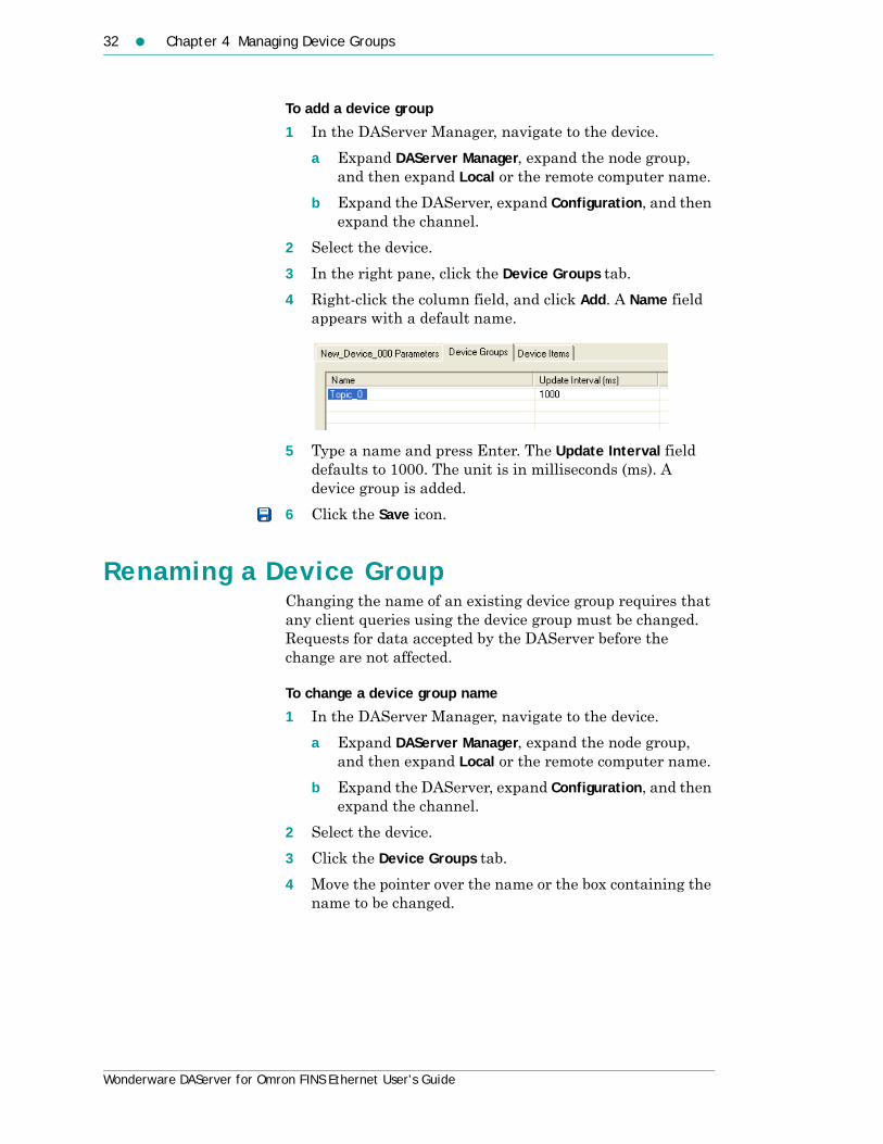
To add a device group
1 In the DAServer Manager, navigate to the device.
a Expand DAServer Manager, expand the node group, and then expand Local or the remote computer name.
b Expand the DAServer, expand Configuration, and then expand the channel.
2 Select the device.
3 In the right pane, click the Device Groups tab.
4 Right-click the column field, and click Add. A Name field appears with a default name.
5 Type a name and press Enter. The Update Interval field defaults to 1000. The unit is in milliseconds (ms). A device group is added.
6 Click the Save icon.
Renaming a Device GroupChanging the name of an existing device group requires that any client queries using the device group must be changed. Requests for data accepted by the DAServer before the change are not affected.
To change a device group name
1 In the DAServer Manager, navigate to the device.
a Expand DAServer Manager, expand the node group, and then expand Local or the remote computer name.
b Expand the DAServer, expand Configuration, and then expand the channel.
2 Select the device.
3 Click the Device Groups tab.
4 Move the pointer over the name or the box containing the name to be changed.
Setting Device Group Data 33
Wonderware DAServer for Omron FINS Ethernet User’s Guide
5 Right-click the name and then click Rename. The name is selected.
6 Type a name and press Enter.
7 Click the Save icon.
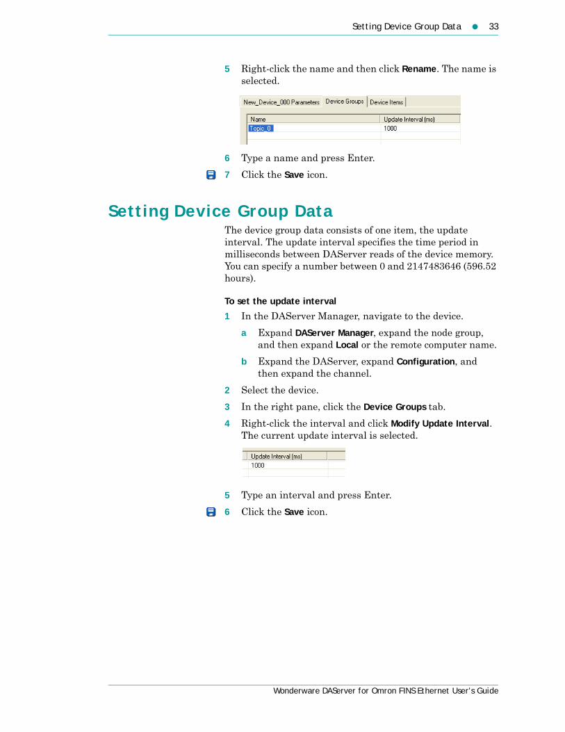
Setting Device Group DataThe device group data consists of one item, the update interval. The update interval specifies the time period in milliseconds between DAServer reads of the device memory. You can specify a number between 0 and 2147483646 (596.52 hours).
To set the update interval
1 In the DAServer Manager, navigate to the device.
a Expand DAServer Manager, expand the node group, and then expand Local or the remote computer name.
b Expand the DAServer, expand Configuration, and then expand the channel.
2 Select the device.
3 In the right pane, click the Device Groups tab.
4 Right-click the interval and click Modify Update Interval. The current update interval is selected.
5 Type an interval and press Enter.
6 Click the Save icon.
34 Chapter 4 Managing Device Groups
Wonderware DAServer for Omron FINS Ethernet User’s Guide
Deleting a Device GroupWhen you delete a device group, the quality of items being accessed using the device group changes to BAD. The DAServer rejects new requests for data using the device group.
To delete a device group
1 In the DAServer Manager, navigate to the device.
a Expand DAServer Manager, expand the node group, and then expand Local or the remote computer name.
b Expand the DAServer, expand Configuration, and then expand the channel.
2 Select the device.
3 In the right pane, click the Device Groups tab.
4 Right-click the group to be deleted and click Delete.
5 Read the warning and then click Yes.
6 Click the Save icon.

35
Wonderware DAServer for Omron FINS Ethernet User’s Guide
Chapter 5
Managing Device Items
Defining device items provides a more user-friendly way to name data in the device. Defining device items is optional. Use device items to access data in the DAServer and devices connected to the DAServer. Device items consist of two pieces: a name and an item reference. You can specify either from your client.
The device item name is an alternative name for the item reference. It is an “alias” or a label for the data in the device. You can use this label instead of the item reference when you create the client application.
The item reference identifies data in the device. The item reference is a PLC memory reference. Each device’s memory reference can have a different format. For more information, see Item Reference Descriptions on page 49.
The actual item reference can be entered as the device item name. In this case, the item reference value can be left empty.
To provide diagnostic and operational information, the DAServer has several system items that do not access data in a device. They are grouped by function:
• Global system items
• Device-group-specific system items
• Device-specific system items
For more information, see Standard System Items on page 49.
Device item names defined in the DAServer show up as OPC browsable items.

36 Chapter 5 Managing Device Items
Wonderware DAServer for Omron FINS Ethernet User’s Guide
You can add device items while the DAServer is active, and these new items are immediately available to client applications.
You can make changes to items while the DAServer is active. Changes take effect immediately. OPC clients that are already connected to the item are not affected until they release and re-acquire the item.
For detailed formats for specifying item references, see Item Reference Descriptions on page 49.
For information on how to subscribe to data items, see Accessing the Data in Your DAServer on page 47.
Creating Aliases for Item ReferencesThe device item name is an alias for the item reference. Device item names can be 256 characters long. Long names may be more explanatory, but your client application may have limited screen space.
To set a device item name
1 In the DAServer Manager, navigate to the device.
a Expand DAServer Manager, expand the node group, and then expand Local or the remote computer name.
b Expand the DAServer, expand Configuration, and then expand the channel.
2 Select the device.
3 In the right pane, click the Device Items tab.
4 Right-click the column and click Add. A Name field is selected with a default name.
5 Type the name and press Enter.
6 Click the Save icon.

Renaming a Device Item 37
Wonderware DAServer for Omron FINS Ethernet User’s Guide
Renaming a Device ItemChanging a device item name affects new client requests for data. Requests for data already accepted by the DAServer are not affected.
To change a device item name
1 In the DAServer Manager, navigate to the device.
a Expand DAServer Manager, expand the node group, and then expand Local or the remote computer name.
b Expand the DAServer, expand Configuration, and then expand the channel.
2 Select the device.
3 In the right pane, click the Device Items tab.
4 Right-click the device item name, and click Rename.
5 Type the new name and press Enter.
6 Click the Save icon.
Deleting a Device ItemDeleting a device item name affects new client requests for data. Requests for data already accepted by the DAServer are not affected.
To delete a device item name
1 In the DAServer Manager, navigate to the device.
a Expand DAServer Manager, expand the node group, and then expand Local or the remote computer name.
b Expand the DAServer, expand Configuration, and then expand the channel.
2 Select the device.
3 In the right pane, click the Device Items tab.
4 Right-click the item to be deleted and click Delete.
5 Read the warning and click Yes.
6 Click the Save icon.

38 Chapter 5 Managing Device Items
Wonderware DAServer for Omron FINS Ethernet User’s Guide
Setting the Item ReferenceYou must know which memory locations you need and the memory location attributes before entering item references in the DAServer.
For more information, see Format and Syntax on page 59.
For tables that list the options for each device type, see Item Reference Descriptions on page 49. In this case device type does not refer to the model of PLC.
To set an item reference
1 In the DAServer Manager, navigate to the device.
a Expand DAServer Manager, expand the node group, and then expand Local or the remote computer name.
b Expand the DAServer, expand Configuration, and then expand the channel.
2 Select the device.
3 Click the Device Items tab.
4 Right-click the Item Reference field to be set and click Rename.
5 Type the item reference and press Enter.
6 Click the Save icon.
Exporting and Importing CSV FilesTo help you manage item references (tags) and device item names outside of the DAServer Manager, the DAServer supports importing and exporting device item data in a comma separated value (CSV) file. The CSV functions are only available when a device items tab is selected.
To export a device item list
1 In the DAServer Manager, navigate to the device.
a Expand DAServer Manager, expand the node group, and then expand Local or the remote computer name.
b Expand the DAServer, expand Configuration, and then expand the channel.
2 Select the device.
3 In the right pane, click the Device Items tab.

Clearing All Device Item Names 39
Wonderware DAServer for Omron FINS Ethernet User’s Guide
4 Right-click the columns field and click Export.
5 In the Save As dialog box, type a file name, select a directory, and click Save.
To import a device item list
1 In the DAServer Manager, navigate to the device.
a Expand DAServer Manager, expand the node group, and then expand Local or the remote computer name.
b Expand the DAServer, expand Configuration, and then expand the channel.
2 Select the device.
3 In the right pane, click the Device Items tab.
4 Right-click the columns field and click Import.
5 In the Open dialog box, find the file containing the items to be imported, and press Open. Items contained in the file are now listed on the Device Items tab.
Clearing All Device Item NamesYou can delete all device items for a device.
To clear all device item names
1 In the DAServer Manager, navigate to the device.
a Expand DAServer Manager, expand the node group, and then expand Local or the remote computer name.
b Expand the DAServer, expand Configuration, and then expand the channel.
2 Select the device.
3 In the right pane, click the Device Items tab.
4 Right-click the columns field and click Clear All.
5 Read the warning and click Yes.
6 Click the Save icon.

40 Chapter 5 Managing Device Items
Wonderware DAServer for Omron FINS Ethernet User’s Guide

41
Wonderware DAServer for Omron FINS Ethernet User’s Guide
Chapter 6
Managing Your DAServer
After you configure the DAServer, there are two steps to take before you can access data with your client application.
The first step is to determine what kind of client applications are to be used with this DAServer. If any of your client applications use DDE/SuiteLink, you must configure the DAServer as a service. If only OPC client applications will be used, you can configure the DAServer as a service or as not a service.
The last step is to activate the DAServer. Some client applications can programatically activate the DAServer. If you configure the DAServer as an automatic service, the DAServer is started and activated when the computer on which the DAServer is installed starts up. If you configure the DAServer as a manual service, the DAServer is not started when the computer starts up. Instead, it is started upon the first connection from an OPC client or when activated from the DAServer Manager.
After a DAServer is running as an auto or manual service, it stays running until explicitly stopped in the DAServer Manager or the computer shuts down.

42 Chapter 6 Managing Your DAServer
Wonderware DAServer for Omron FINS Ethernet User’s Guide
Configuring the DAServer as ServiceTo support DDE/SuiteLink clients, the DAServer must be configured as a service.
To configure the DAServer as a service
1 In the DAServer Manager, navigate to the DAServer.• Expand DAServer Manager, expand the node group,
and then expand Local or the remote computer name.
2 Right-click ArchestrA.DASOMFINSEnet.1 and then click Configure As Service.
3 Click either Auto Service or Manual Service.
4 Read the warning message and click Yes.
Configuring the DAServer as Not a ServiceThe DAServer can only be set to run as not a service when the DAServer is in the deactivated state.
To configure the DAServer as not a service
1 In the DAServer Manager, navigate to the DAServer.• Expand DAServer Manager, expand the node group,
and then expand Local or the remote computer name.
2 Right-click ArchestrA.DASOMFINSEnet.1 and then click Configure As Service.
3 Click Not a Service.
4 Read the warning message and click Yes.
Archiving Configuration SetsA configuration set includes the DAServer’s global parameters; each channel and its parameters; and each device and its parameters, device groups, and device items. It lets you manage the settings of different DAServer configurations.
The DAServer contains a default configuration set named DASOMFINSEnet. You cannot delete the default configuration set.
You can create multiple configuration sets and switch between them. Archiving, clearing, and switching configuration sets can only be done when the DAServer is deactivated.
Archiving Configuration Sets 43
Wonderware DAServer for Omron FINS Ethernet User’s Guide
Before you create a configuration set, verify that you have saved any changes you made to the global parameters. If you change a parameter and then immediately create a configuration set, the original parameter value is saved as part of the configuration set, not the changed value.
To save a global parameter, click the Save icon.
To archive a configuration set
1 In the DAServer Manager, navigate to the configuration node.
a Expand DAServer Manager, expand the node group, and then expand Local or the remote computer name.
b Expand the DAServer.
2 Click Configuration.
3 Right-click and click Archive Configuration Set.
4 In the dialog box, type the configuration set name, and click Archive. All the current configuration values are saved to the set.
After you archive at least one configuration set, you can select it for use.
To select a configuration set
1 In the DAServer Manager, navigate to the configuration node.
a Expand DAServer Manager, expand the node group, and then expand Local or the remote computer name.
b Expand the DAServer.
2 Click Configuration.
3 Right-click, point to Use Another Configuration Set, then click the desired name.
To change the parameter values saved in a configuration set, make sure the desired configuration set is shown, then follow this procedure.
To change the parameter values in a configuration set
1 In the DAServer Manager, navigate to the configuration node.
a Expand DAServer Manager, expand the node group, and then expand Local or the remote computer name.
b Expand the DAServer.

44 Chapter 6 Managing Your DAServer
Wonderware DAServer for Omron FINS Ethernet User’s Guide
2 Click Configuration.
3 Change the parameters that you want to change.
4 Click the Save icon.Clearing a configuration set returns the parameters to their default values.
To clear a configuration set
1 In the DAServer Manager, navigate to the configuration node.
a Expand DAServer Manager, expand the node group, and then expand Local or the remote computer name.
b Expand the DAServer.
2 Click Configuration.
3 Right-click, move the mouse over Clear Configuration Set, then left click.
4 Read the warning message, then click Yes. The parameters are set to the default values.
To delete a configuration set
1 In the DAServer Manager, navigate to the configuration node.
a Expand DAServer Manager, expand the node group, and then expand Local or the remote computer name.
b Expand the DAServer.
2 Click Configuration.
3 Right-click Configuration, point to Delete Configuration Set and select the configuration set to delete.
4 Read the warning message, then click Yes.
Activating/Deactivating the DAServerWhen you activate the DAServer, it starts communicating and accepting requests from client applications. If a DAServer is configured as an automatic service, the DAServer is started and activated when the computer starts up. Also, a DAServer can be activated by the an OPC client connection request.

In-Proc/Out-of-Proc 45
Wonderware DAServer for Omron FINS Ethernet User’s Guide
To activate the DAServer
1 In the DAServer Manager, navigate to the DAServer.• Expand DAServer Manager, expand the node group,
and then expand Local or the remote computer name.
2 Right-click ArchestrA.DASOMFINSEnet.1 and then click Activate Server.
Deactivating your DAServer stops it from communicating with client applications.
A DAServer with active OPC clients does not stop until the last OPC client shuts down.
To deactivate the DAServer
1 In the DAServer Manager, navigate to the DAServer.• Expand DAServer Manager, expand the node group,
and then expand Local or the remote computer name.
2 Right-click ArchestrA.DASOMFINSEnet.1 and then click Deactivate Server.
3 Read the warning message and click Yes.
In-Proc/Out-of-ProcThe DAServer can run as a stand-alone process (out-of-proc) or as part of the client process (in-proc).
When the DAServer is running out-of-proc, it supports requests from both DDE/SuiteLink and OPC client applications. When the DAServer is running in-proc, it only supports OPC client applications.
If the DAServer is running as a service, the icon on the DAServer node in the SMC is yellow. If the DAServer is running as not a service, the icon is white. For more information, see the DAServer Manager User’s Guide.
Hot ConfigurationThe DAServer allows certain configuration parameters to be changed while the DAServer is active. See the sections about the specific parameters for limitations or constraints.

46 Chapter 6 Managing Your DAServer
Wonderware DAServer for Omron FINS Ethernet User’s Guide
Demo ModeYou can install the DAServer without a license. The DAServer runs without a license in Demo mode for 120 minutes. While in demo mode the DAServer checks for a license every 30 seconds. When the 120 minutes expires:
• the DAServer stops updating items.
• all non-system items have a Bad quality status.
• new items are rejected.
After the 120 minutes the DAServer checks for a license every thirty seconds. If a license is not found, the DAServer logs a warning.
You can use the $SYS$Licensed system item to check the status of your license. This item returns true if the proper license is found or the DAServer is in demo mode (the 120 minutes), otherwise, it returns false.
After the DAServer finds a valid license, it logs a message, stops looking for a license, and begins running normally. For more information, see the License Utility User Guide.

47
Wonderware DAServer for Omron FINS Ethernet User’s Guide
Chapter 7
Accessing the Data in YourDAServer
Client applications read and write to data items that are internal to the DAServer, as well as to the items located in the devices. Client application communication with the DAServer is done using either the OPC, or DDE/SuiteLink protocols. The client application may or may not be on the same computer as the DAServer.
You do not need to create device items in the DAServer for your OPC client application.
For information on how to specify item references, see Format and Syntax on page 59. For information on specific address formats, see Address Descriptions on page 64.

48 Chapter 7 Accessing the Data in Your DAServer
Wonderware DAServer for Omron FINS Ethernet User’s Guide
Accessing Data Using OPCTo connect to the DAServer with an OPC client application, be aware of the following six parameters:
• node name: The computer name identifying the node where the DAServer is located. Only required for remote access.
• program name: ArchestrA.DASOMFINSEnet.1
• group name: An OPC group defined and created by the client. The DAServer device group is used as the OPC access path.
• device group: A device group as defined on the DAServer. If omitted, the default device group is assumed.
• link name: The hierarchy of nodes names, from the channel node to the device node, separated by delimiters.
• item name: The specific data element. This can be the device item name or the item reference.
The combination of the link name and item name form the OPC data path for any OPC client to access DAServer data.
If the item specified is not valid for the device location, the DAServer does not accept the item. The DAServer returns bad quality and generates an error message in the logger.
Accessing Data Using DDE/SuiteLinkThe DDE/SuiteLink address has four fields:
• node name: The computer name identifying the node where the DAServer is located. Only required for remote access.
• application name: DASOMFINSEnet
• topic name: A device group defined for the device.
• item name: The specific data element. This can be the device item name or the item reference.
The DDE/SuiteLink topic is the equivalent to the device group.

49
Wonderware DAServer for Omron FINS Ethernet User’s Guide
Chapter 8
Item Reference Descriptions
You use item references to access system items and read and write data from devices.
Standard System ItemsSystem items provide you easy access to DAServer status and diagnostics information. Client applications can read data from them just like ordinary items. However, in most cases the system item values are not directly acquired through the communications layer. System item values are usually generated through internal calculations, measurements, and tracking by the DAS Engine.
System items, like ordinary items, are defined by the following properties:
• Group: The client group/OPC group is an arbitrary collection of items, not correlated.
• Hierarchical location: The device attached to the item, indicated by link name/OPC path. The path contains the hierarchical node section of the fully qualified OPC item ID.
• Device group: A collection of items on the same physical location with the same protocol update rate. The device group is ndicated by OPC access path/topic.
50 Chapter 8 Item Reference Descriptions
Wonderware DAServer for Omron FINS Ethernet User’s Guide
For DDE/SuiteLink clients, $SYS$Status always comes from the leaf level of a DAServer hierarchy branch, which is the destination PLC node. For OPC clients, $SYS$Status can be accessed at all hierarchy levels. $SYS$Status at the root level of the whole hierarchy tree is always good, as it represents the quality status of the local computer itself. For practical application, OPC clients should reference $SYS$Status at any hierarchy levels other than the root.
All system items follow the same naming convention:
• All system items start with $SYS$.
• The DAS Engine scans and parses the name for system items.
• Parsing of the name is case-insensitive.
All system items can be accessed through subscriptions to a device group. However, while some system items return data for that device group, others are server-wide.
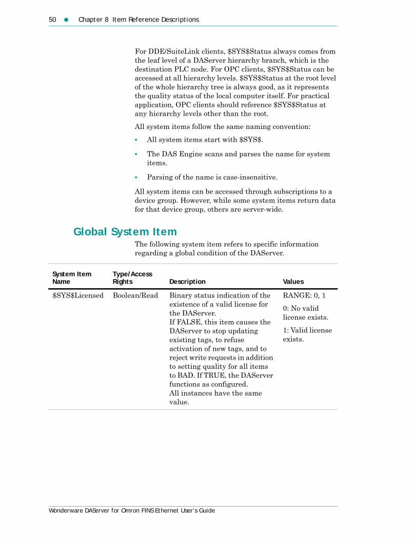
Global System ItemThe following system item refers to specific information regarding a global condition of the DAServer.
System Item Name
Type/Access Rights Description Values
$SYS$Licensed Boolean/Read Binary status indication of the existence of a valid license for the DAServer. If FALSE, this item causes the DAServer to stop updating existing tags, to refuse activation of new tags, and to reject write requests in addition to setting quality for all items to BAD. If TRUE, the DAServer functions as configured. All instances have the same value.
RANGE: 0, 1
0: No valid license exists.
1: Valid license exists.

Standard System Items 51
Wonderware DAServer for Omron FINS Ethernet User’s Guide
Device-Group-Specific System ItemsThe following system items refer to specific information regarding device groups that are configured in the DAServer.
System Item Name (Type)
Type/Access Rights Description Values
$SYS$UpdateInterval DWord/ReadWrite
Accesses the currently set update interval. It is the current update interval of the device group in milliseconds. A client can poke new values into this item. The value of zero indicates that non-system items on that topic are not updated. Data for these items are not acquired from the device.
RANGE: 1…2147483647
0: Topic inactive, no items are updated. Data acquisition is stopped.
>0: Expected updated interval for the set of all items in the device group.
$SYS$MaxInterval DWord/Read Not supported by this DAServer.
Always returns zero.

52 Chapter 8 Item Reference Descriptions
Wonderware DAServer for Omron FINS Ethernet User’s Guide
$SYS$WriteComplete Integer/ReadWrite
Accesses the state of pending write activities on the corresponding device group. On device group creation (adding items to an OPC group), the value of this system item is initially 1, indicating all write activities are complete – no pokes are pending.
If values are poked into any items of the device group, the value of this item changes to 0, indicating write activity is currently in progress. If the server has completed all write activities, the value of this item changes to 1 if all pokes were successful or to -1 if at least one poke has failed.
If the value of this item is not zero, you can poke 1 or -1 to it. Poke a 1 to clear errors, or a -1 to test a client reaction on write errors. If the value of this item is zero, it cannot be poked.
RANGE: -1, 0, 1
-1: Writes completed with errors.
0: Writes are pending.
1: Write complete. No writes are pending – initial state.
System Item Name (Type)
Type/Access Rights Description Values
Standard System Items 53
Wonderware DAServer for Omron FINS Ethernet User’s Guide
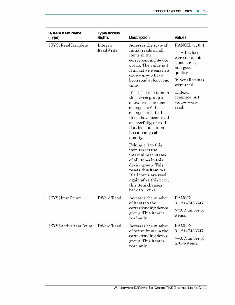
$SYS$ReadComplete Integer/ ReadWrite
Accesses the state of initial reads on all items in the corresponding device group. The value is 1 if all active items in a device group have been read at least one time.
If at least one item in the device group is activated, this item changes to 0. It changes to 1 if all items have been read successfully, or to -1 if at least one item has a non-good quality.
Poking a 0 to this item resets the internal read states of all items in this device group. This resets this item to 0. If all items are read again after this poke, this item changes back to 1 or -1.
RANGE: -1, 0, 1
-1: All values were read but some have a non-good quality.
0: Not all values were read.
1: Read complete. All values were read.
$SYS$ItemCount DWord/Read Accesses the number of items in the corresponding device group. This item is read-only.
RANGE: 0…2147483647
>=0: Number of items.
$SYS$ActiveItemCount DWord/Read Accesses the number of active items in the corresponding device group. This item is read-only.
RANGE: 0…2147483647
>=0: Number of active items.
System Item Name (Type)
Type/Access Rights Description Values

54 Chapter 8 Item Reference Descriptions
Wonderware DAServer for Omron FINS Ethernet User’s Guide
$SYS$ErrorCount DWord/Read Accesses the number of all active and inactive items that have non-good OPC quality errors in the corresponding topic.If the communications status of a device group is bad, all items have errors. This item is read-only.
RANGE: 0…2147483647
>=0: Number of all active and inactive items with errors.
$SYS$PollNow Boolean/ReadWrite
Not supported by this DAServer.
System Item Name (Type)
Type/Access Rights Description Values

Device-Specific System Items 55
Wonderware DAServer for Omron FINS Ethernet User’s Guide
Device-Specific System ItemsThe following system items refer to specific information regarding the device(s) the DAServer is connected to.
System Item Name (Type)
Type/Access Rights Description Values
$SYS$Status Boolean/Read Binary status indication of the connection state to the device (hierarchy level) the item is attached to. The device group (OPC access path/topic) does not affect the value.
The status can be good even if individual items have errors.
For DDE/SuiteLink clients, $SYS$Status always comes from the leaf level of a DAServer hierarchy branch, which is the destination PLC node. For OPC clients, $SYS$Status can be accessed at all hierarchy levels. $SYS$Status at the root level of the whole hierarchy tree is always good, as it represents the quality status of the local computer itself. For practical application, OPC clients should reference $SYS$Status at any hierarchy levels other than the root.
RANGE: 0, 1
0: Error communicating with the device.
1: DAServer connection to the device is intact.

56 Chapter 8 Item Reference Descriptions
Wonderware DAServer for Omron FINS Ethernet User’s Guide
$SYS$ErrorCode Longint/Read Detailed error code of the communications state to the device.
The device group (OPC access path/topic) does not affect the value.
>= 0: Good status. 0 is the default state – connected.
>0: Some device state like: connecting, initializing, and so on.
<0: Error status. Value indicates the error.
$SYS$ErrorText String/Read Detailed error string of the communications state of the device.
The device group (OPC access path/topic) does not affect the value.
Descriptive text for the communications state corresponding to the error code.
System Item Name (Type)
Type/Access Rights Description Values

Device-Specific System Items 57
Wonderware DAServer for Omron FINS Ethernet User’s Guide
$SYS$StoreSettings Integer/ReadWrite
Makes the temporary update interval changes via the $SYS$UpdateInterval item permanent. If the client pokes a value of 1 into this system item, the currently set update interval is written to the server’s configuration file. The value of this system item clears to 0 after being set, if the configuration file write is successful. If the write fails, then the value is set to -1.If the update interval changes via the $SYS$UpdateInterval item and this item is not poked to 1, the DAServer uses the original update interval for that topic the next time it is started.
Reading the item always provides 0. Read/Write values are persisted only if you set this system item. The values other than this persist only for the life of the DAServer.
RANGE: -1, 0, 1
-1: Error occurred while saving the configuration file.
0: Read value always if status is OK.
1: Persist settings. Cleared immediately.
System Item Name (Type)
Type/Access Rights Description Values

58 Chapter 8 Item Reference Descriptions
Wonderware DAServer for Omron FINS Ethernet User’s Guide
Supported Data TypesThe data type is specified as a suffix in the item syntax. The DAServer supports the following data types.
Data Type Description
Boolean Single bit
Short Signed 16 bit value. Bit 0 is the low bit. Bit 14 is the high bit. Bit 15 is the sign bit.
Word Unsigned 16 bit value. Bit 0 is the low bit. Bit 15 is the high bit.
Long Signed 32 bit value. Bit 0 is the low bit. Bit 30 is the high bit. Bit 31 is the sign bit.
DWord Unsigned 32 bit value. Bit 0 is the low bit. Bit 31 is the high bit.
Float 32 bit floating point value.
BCD Two byte packed BCD. Value range is 0 - 9999. Behavior is undefined for values beyond this range.
LBCD Four byte packed BCD. Value range is 0 -99999999. Behavior is undefined for values beyond this range.
String Null terminated ASCII string. Support includes HiLo and LoHi byte order selection and string lengths up to 512 characters.

Format and Syntax 59
Wonderware DAServer for Omron FINS Ethernet User’s Guide
Format and SyntaxItem references have four attributes:
• Device Type defines what the memory location can be used for. Device types include inputs, outputs, link relays, latch relays, and others. For device type limitations, see your PLC documentation. In this case, device type does not refer to the model of PLC.
• Range defines the valid addresses. Addresses are usually specified as one or more letters indicating the device type and a number. The number is specified as a hex or decimal value from 0 to an upper limit. Hexadecimal numbers must always start with a valid decimal digit. For example, the offset C3 is written as 0C3.
• Data Type defines which data type the client request can specify when accessing the memory location. Examples are Short and Word. For a complete list of valid data types, see Supported Data Types on page 58. The data type is often optional because most memory locations have a default data type.
• Access defines what the client can do. Some memory locations are read only or write only, others are read/write.
You can use optional item name suffixes to change the default server data format. The suffixes are listed in the Supported Suffixes columns of the Address Descriptions on page 64.
Note Item name suffixes are case insensitive.
Unsigned/Signed FormatThe server can interpret data in 16-bit signed format (-32768 to 32767).
For example, channel DM100 in a C200H PLC contains 8000 hex. Unsigned quantities are read from this channel by one of two methods,
• Enter the item name.
• Append the letter U to the item name.
Therefore, item name DM100 or DM100U appears in InTouch or Excel as 32768.

60 Chapter 8 Item Reference Descriptions
Wonderware DAServer for Omron FINS Ethernet User’s Guide
Signed quantities can be read from this same channel by appending the letter S to the item name. Therefore, item name DM100S appears in InTouch or Excel as -32768.
For tables showing allowable usage for each memory address, see Address Descriptions on page 64.
BCD FormatThe OMRON PLC family supports BCD (Binary Coded Decimal) data representation and manipulation within their instruction sets.
To read or write data using BCD format, append the letter B to the item name. The @BCD suffix can also be used.
For example, the item name DM100B or DM100@BCD reads and writes a channel in BCD format.
Long Format (Signed/BCD)Two consecutive 16-bit words in a PLC can be interpreted as a 32-bit long integer. It can be formatted as either signed (-2,147,483,648 to 2,147,483,648) or BCD (0 to 99,999,999).
To read or write an item in signed long format, append the letter L to the item name. You can also use the @long suffix.
To read or write an item in BCD long format, append the letter M to the item name. You can also use the @LBCD suffix.
For example, if DM100 contains 0234 hex and DM101 contains 1356 hex, DM100L or DM100@long returns 324,403,764 and DM100M or DM100@LBCD returns 13,560,234.
Floating Point Format (IEEE)Two consecutive 16-bit words in a PLC can be interpreted as a single precision floating point number. It is formatted as
either IEEE (-3.402823×1038 to + 3.402823×1038).
To read or write an item in IEEE floating point format, append the letter F to the item name.
Note IEEE format is NOT supported in the C-Series PLC family.

Format and Syntax 61
Wonderware DAServer for Omron FINS Ethernet User’s Guide
ASCII Strings FormatMultiple consecutive 16-bit words (block size of 1 to 29) in a PLC can be interpreted as a string of ASCII characters. The ASCII string is stored/retrieved from the lowest-numbered address to the highest, and from the high-order byte to the low-order byte with each address.
To define a range of words, use a dash ( - ) between the two address locations. For example, DM10-DM12 indicates locations from DM10 to DM12.
ASCII string characters can be specified to come from the low-order byte, high-order byte, or both bytes of the words.
• Low-order Byte: Only the low-order byte (LSB - least significant 8-bits) of each word is used for read/write.
To use this format, append the letter E to the item name.
• High-order Byte: Only the high-order byte (MSB - most significant 8-bits) of each word is used for read/write.
To use this format, append the letter D to the item name.
• Both Bytes: Both bytes of each word are used for read/write.
To use this format, append the letter C to the item name.
Note All bytes in the specified memory range are used.
If the string is shorter than the range of memory specified, it is padded with \0. If the string is longer than the range of memory specified, the string will be truncated.
For example, assume the following memory contents (numeric values shown in hex):
Read:
• DM10 - DM12C returns ABCDEF
• DM10 - DM12D returns ACE
• DM10 - DM12E returns BDF
Item Reference MSB LSB ASCII Equivalent
DM10 41 42 AB
DM11 43 44 CD
DM12 45 46 EF

62 Chapter 8 Item Reference Descriptions
Wonderware DAServer for Omron FINS Ethernet User’s Guide
Write:
• DM10 - DM12C after written with "Test"
• DM10 - DM12E after written with “ABCDE”
Alternate ASCII String FormatYou can use the following ASCII String Format only with Data Memory (DM), Expansion Data Memory (EM), and Core IO Channel (CIO) device types.
When you use data memory for string data, each register contains two bytes (two characters) of ASCII data. The order of the ASCII data within a given register can be selected when the string is defined.
The length of the string can be from 2 to 58 characters. The length is entered in place of a bit number and must be an even number.
The range of registers spanned by the string cannot exceed the range of the device type. The byte order is specified by appending either an H or an L to the address.
For example:
• You address a string starting at DM100 with a length of 20 bytes and HiLo byte as DM100.20H.
• You address a string starting at DM110 with a length of 24 bytes and LoHi byte as DM110.24L.
Item Reference MSB LSB ASCII Equivalent
DM10 54 65 Te
DM11 73 74 st
DM12 0 0 “ “
Item Reference MSB LSB ASCII Equivalent
DM10 0 41 A
DM11 0 42 B
DM12 0 43 C

Format and Syntax 63
Wonderware DAServer for Omron FINS Ethernet User’s Guide
Bit AccessIndividual bits of register device types can be accessed as Booleans. To reference a particular bit, append a bit number .bb (.bit) or :bb (:bit) to the address of the register.
The bit number is always in decimal notation.
• 0 - 15 for Short, Word, BCD
• 0 - 31 for Long, DWord, and LBCD
For example:
• D1.0 or D1:0 is the least significant bit of D1.
• D1.15 or D1:15 is the most significant bit of D1.
Array AccessYou can use arrays with all data types except Boolean. The number of array elements cannot exceed the request size that has been assigned to the device.
For example DMxxxx [elements].
For DDE/SuiteLink client, array data is returned as a string in HexASCII format.
Using 32-bit ValuesBe careful when modifying 32-bit values (DWord, Long, LBCD, and Float). Each address for which these data types are allowed can start at any word offset. For example, writes to DWords DM0 (referencing words 0 and 1) and DM1 (referencing words 1 and 2) both change word DM1.
It is recommended that you use these data types so that overlapping does not occur. For example, when using DWords, you might want to use DM0, DM2, DM4, and so on, to prevent overlapping words.

64 Chapter 8 Item Reference Descriptions
Wonderware DAServer for Omron FINS Ethernet User’s Guide
Address DescriptionsThe address descriptions consist of the device type, its item name and the allowable range of values, the default data type, allowable suffix values,and allowable access methods.
C200 Address DescriptionsModel C200 supports the following types of devices.
Note Expansion Data Memory in the C200 Series PLC can be accessed using syntax EA, EB, EC...where EA refers to EM0 memory area of the PLC, and so on. The range of the Expansion Data Memory depends upon the CPU type.
Device Type Item Name RangeData Type
Supported Suffixes Access
Auxiliary Relay
ARn n=00 to 27 Word @word, @short, @BCD,u,s,b,d,e,c
Read/Write
n=00 to 26 @long, @dword, @LBCD,@floatl,f,m
n=xx:pp or
n=xx.pp,
xx=00 to 27,
pp=00 to 15
Boolean

Address Descriptions 65
Wonderware DAServer for Omron FINS Ethernet User’s Guide
Data Memory DMn n=0000 to 6655 Word @word, @short, @BCD,u,s,b,d,e,c
Read/Write
n=0000 to 6654 @long, @dword, @LBCD,@floatl,f,m
n=xxxx.pp or n=xxxx:pp, xxxx=0000 to 6655, pp=00 to 15
Boolean
n=xxxx.yyyH xxxx=0000 to 6655 yyy=002 to 512 (String length must be an even number).
String (with HiLo byte order)
Read/Write
n=xxxx.yyyL xxxx=0000 to 6655 yyy=002 to 512 (String length must be an even number).
String (with LoHi byte order)
Read/Write
Device Type Item Name RangeData Type
Supported Suffixes Access

66 Chapter 8 Item Reference Descriptions
Wonderware DAServer for Omron FINS Ethernet User’s Guide
Expansion Data Memory EM (current bank)
EMn n=0000 to 6143 Word @word,@short,@BCD,u,s,b,d,e,c
Read/Write
n=0000 to 6142 @long,@dword,@LBCD,@float,l,f,m
n=xxxx.pp or
n=xxxx:pp, xxxx=0000 to 6143,pp=00 to 15
Boolean
n=xxxx.yyyH, xxxx=0000 to 6143,yyy=002 to 512 (String length must be an even number).
String (with HiLo byte order)
Read/Write
n=xxxx.yyyL, xxxx=0000 to 6143,yyy=002 to 512 (String length must be an even number).
String (with LoHi byte order)
Read/Write
Device Type Item Name RangeData Type
Supported Suffixes Access

Address Descriptions 67
Wonderware DAServer for Omron FINS Ethernet User’s Guide
Expansion Data Memory
En n=zxxxx,z=A to H, xxxx=0000 to 6143
Word @word,@short,@BCD,u,s,b,d,e,c
Read/Write
n=zxxxx,z=A to H, xxxx=0000 to 6142
@dword,@long,@LBCD,@float,l,f,m
n=zxxxx.pp or n=zxxxx:pp,z=A to H, xxxx=0000 to 6143 pp=00 to 15
Boolean
n=zxxxx.yyyH, z=A to H, xxxx=0000 to 6143, yyy=002 to 512 (String length must be an even number)
String (with HiLo byte order)
Read/Write
n=zxxxx.yyyL, z=A to H, xxxx=0000 to 6143, yyy=002 to 512 (String length must be an even number)
String (with LoHi byte order)
Read/Write
Device Type Item Name RangeData Type
Supported Suffixes Access
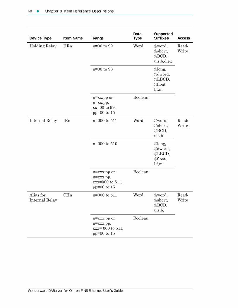
68 Chapter 8 Item Reference Descriptions
Wonderware DAServer for Omron FINS Ethernet User’s Guide
Holding Relay HRn n=00 to 99 Word @word,@short,@BCD,u,s,b,d,e,c
Read/Write
n=00 to 98 @long,@dword,@LBCD,@floatl,f,m
n=xx:pp or n=xx.pp,xx=00 to 99,pp=00 to 15
Boolean
Internal Relay IRn n=000 to 511 Word @word,@short,@BCD,u,s,b
Read/Write
n=000 to 510 @long,@dword,@LBCD,@float,l,f,m
n=xxx:pp orn=xxx.pp,xxx=000 to 511, pp=00 to 15
Boolean
Alias for Internal Relay
CHn n=000 to 511 Word @word,@short,@BCD, u,s,b,
Read/Write
n=xxx:pp or n=xxx.pp, xxx= 000 to 511, pp=00 to 15
Boolean
Device Type Item Name RangeData Type
Supported Suffixes Access

Address Descriptions 69
Wonderware DAServer for Omron FINS Ethernet User’s Guide
Link Relays LRn n=00 to 63 Word @word,@short,@BCD, u,s,b,d,e,c
Read/Write
n=00 to 62 @long,@dword,@LBCD,@float,l,f,m
n=xx:pp or n=xx.pp, xx= 00 to 63, pp=00 to 15
Boolean
Timer/Counter PVn n=000 to 511 Word @word,@short,@BCD, u,s,b,d,e,c
Read/Write
Timer/Counter Status
TCn n=000 to 511 Boolean Read Only
Device Type Item Name RangeData Type
Supported Suffixes Access

70 Chapter 8 Item Reference Descriptions
Wonderware DAServer for Omron FINS Ethernet User’s Guide
CV500 Address DescriptionsModel CV500 supports the following types of devices.
Device Type Item Name Range Data TypeSupported Suffixes Access
Action Flag ACn n=0000 to 1023 Boolean Read Only
Auxiliary Relay
An n=000 to 255 Word @word,@short,@BCD,u,s,b,d,e,c
Read/Write
n=000 to 254 @long,@dword,@LBCD,@float,f,l,m
n=256 to 511 Word @word,@short,@BCD,u,s,b,d,e,c
Read Only
n=256 to 510 @long,@dword,@LBCD,@float,f,l,m
n= xxx.pp or n=xxx:pp, xxx= 000 to 255,pp=00 to15
Boolean Read/Write
n= xxx.pp or n=xxx:pp, xxx= 256 to 511, pp=00 to15
Boolean Read Only

Address Descriptions 71
Wonderware DAServer for Omron FINS Ethernet User’s Guide
Core I/O Channel
CIOn n=0000 to 2555 Word @word,@short,@BCD,u,s,b,d,e,c
Read/Write
n=0000 to 2554 @long,@dword,@LBCD,@float,f,l,m
n= xxxx.pp or n=xxxx:pp, xxxx= 0000 to 2555, pp=00 to15
Boolean
n=xxxx.yyyH, xxxx=0000 to 2555, yyy=002 to 512 (String length must be an even number.)
String (with HiLo byte order.)
n=xxxx.yyyL, xxxx=0000 to 2555, yyy=002 to 512 (String length must be an even number.)
String (with LoHi byte order.)
Counter PVCn n=000 to 511 Word @word,@short,@BCD,u,s,b,d,e,c
Read/Write
Counter Status
Cn n=000 to 511 Boolean Read Only
Device Type Item Name Range Data TypeSupported Suffixes Access

72 Chapter 8 Item Reference Descriptions
Wonderware DAServer for Omron FINS Ethernet User’s Guide
CPU Bus Link Gn n=000 to 255 Word @word,@short,@BCD,u,s,b,d,e,c
Read/Write
n=000 to 254 @long,@dword,@LBCD,@float,f,l,m
n= xxx.pp or n=xxx:pp, xxx= 000 to 255,pp=00 to15
Boolean
Data Memory Dn n=0000 to 8191 Word @word,@short,@BCD,u,s,b,d,e,c
Read/Write
n=0000 to 8190 @long,@dword,@LBCD,@float,f,l,m
n= xxxx.pp or n=xxxx:pp, xxxx= 0000 to 8191, pp=00 to15
Boolean
n=xxxx.yyyH xxxx=0000 to 8191, yyy=002 to 512 (String length must be an even number.)
String (with HiLo byte order)
Read/Write
n=xxxx.yyyL xxxx=0000 to 8191, yyy=002 to 512 (String length must be an even number.)
String (with LoHi byte order)
Read/Write
Device Type Item Name Range Data TypeSupported Suffixes Access
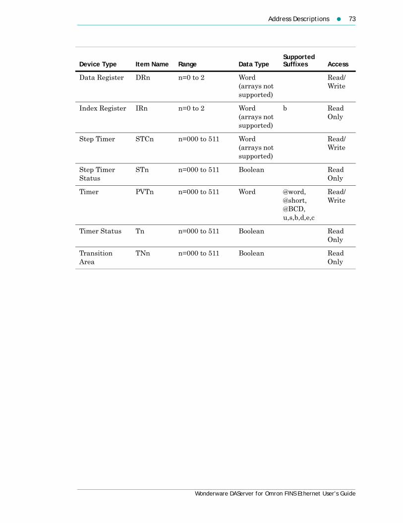
Address Descriptions 73
Wonderware DAServer for Omron FINS Ethernet User’s Guide
Data Register DRn n=0 to 2 Word (arrays not supported)
Read/Write
Index Register IRn n=0 to 2 Word(arrays not supported)
b Read Only
Step Timer STCn n=000 to 511 Word(arrays not supported)
Read/Write
Step Timer Status
STn n=000 to 511 Boolean Read Only
Timer PVTn n=000 to 511 Word @word,@short,@BCD,u,s,b,d,e,c
Read/Write
Timer Status Tn n=000 to 511 Boolean Read Only
Transition Area
TNn n=000 to 511 Boolean Read Only
Device Type Item Name Range Data TypeSupported Suffixes Access

74 Chapter 8 Item Reference Descriptions
Wonderware DAServer for Omron FINS Ethernet User’s Guide
CV1000 and CV2000 Address DescriptionsModels CV1000 and CV2000 support the following types of devices.
Note Expansion Data Memory in CV1000/CV2000 Series PLCs can be accessed using syntax EA, EB, EC...where EA refers to the E0 memory area of the PLC, and so on. The range of the Expansion Data Memory depends on the CPU type.
Device TypeItem Name Range Data Type
Supported Suffixes Access
Action Flag ACn n=0000 to 2047 Boolean Read Only
Auxiliary Relay
An n=000 to 255 Word @word,@short,@BCD,u,s,b,d,e,c
Read/Write
n=000 to 254 @long,@dword,@LBCD,@float, f,l,m
n=256 to 511 Word @word,@short,@BCD,u,s,b,d,e,c
Read Only
n=256 to 510 @long,@dword,@LBCD,@float, f,l,m
n= xxx.pp or n=xxx:pp, xxx= 000 to 255,pp=00 to 15
Boolean Read/Write
n= xxx.pp or n=xxx:pp, xxx= 256 to 511,pp=00 to15
Boolean Read Only

Address Descriptions 75
Wonderware DAServer for Omron FINS Ethernet User’s Guide
Core I/O Channel
CIOn n=0000 to 2555 Word @word,@short,@BCD,u,s,b,d,e,c
Read/Write
n=0000 to 2554 @long,@dword,@LBCD,@float, f,l,m
n= xxxx.pp or n=xxxx:pp, xxxx= 0000 to 2555, pp=00 to 15
Boolean
n=xxxx.yyyH, xxxx=0000 to 2555, yyy=002 to 512 (String length must be an even number.)
String (with HiLo byte order.)
n=xxxx.yyyL, xxxx=0000 to 2555, yyy=002 to 512 (String length must be an even number.)
String (with LoHi byte order.)
Counter PVCn n=000 to 1023 Word @word,@short,@BCD, u,s,b,d,e,c
Read/Write
Counter Status
Cn n=000 to 1023 Boolean Read Only
Device TypeItem Name Range Data Type
Supported Suffixes Access

76 Chapter 8 Item Reference Descriptions
Wonderware DAServer for Omron FINS Ethernet User’s Guide
CPU Bus Link
Gn n=000 to 255 Word @word,@short,@BCD,u,s,b,d,e,c
Read/Write
n=000 to 254 @long,@dword,@LBCD,@float, f,l,m
n= xxx.pp or n=xxx:pp, xxx= 000 to 255,pp=00 to15
Boolean
Data Memory Dn n=00000 to 24575
Word @word,@short,@BCD,u,s,b,d,e,c
Read/Write
n=00000 to 24574
@long,@dword,@LBCD,@float, f,l,m
n= xxxxx.pp or n=xxxxx:pp, xxxxx= 00000 to 24575, pp=00 to15
Boolean
n=xxxxx.yyyH xxxxx=00000 to 24575, yyy=002 to 512 (String length must be an even number.)
String (with HiLo byte order)
Read/Write
n=xxxxx.yyyL xxxxx=00000 to 24575,yyy=002 to 512 (String length must be an even number.)
String (with LoHi byte order)
Read/Write
Device TypeItem Name Range Data Type
Supported Suffixes Access

Address Descriptions 77
Wonderware DAServer for Omron FINS Ethernet User’s Guide
Data Register DRn n=0 to 2 Word(arrays not supported)
Read/Write
Expansion Data Memory (current bank)
En n=00000 to 32765
Word @word,@short,@BCD,u,s,b,d,e,c
Read/Write
n=00000 to 32764
@long,@dword,@LBCD,@float,f,l,m
n= xxxxx.pp or n=xxxxx:pp,xxxxx= 00000 to 32765,pp=00 to15
Boolean
n=xxxxx.yyyH xxxxx=00000 to 32765,yyy=002 to 512 (String length must be an even number.)
String (with HiLo byte order)
Read/Write
n=xxxxx.yyyL xxxxx=00000 to 32765,yyy=002 to 512 (String length must be an even number.)
String (with LoHi byte order)
Read/Write
Device TypeItem Name Range Data Type
Supported Suffixes Access

78 Chapter 8 Item Reference Descriptions
Wonderware DAServer for Omron FINS Ethernet User’s Guide
Expansion Data Memory
En n=zxxxxx,z=A to H, xxxxx=00000 to 32765
Word @word,@short,@BCD,u,s,b,d,e,c
Read/Write
n=zxxxxx, z=A to H, xxxxx=00000 to 32764
@long,@dword,@LBCD,@float, f,l,m
n=zxxxxx.pp or n=zxxxxx:pp, z = A to H, xxxxx=00000 to 32765, pp=00 to 15
Boolean
n=zxxxxx.yyyH, z=A to H, xxxxx=00000 to 32765, yyy=002 to 512 (String length must be an even number.)
String (with HiLo byte order)
Read/Write
n=zxxxxx.yyyL, z=A to H, xxxxx=00000 to 32765, yyy=002 to 512 (String length must be an even number.)
String (with LoHi byte order)
Read/Write
Index Register
IRn n=0 to 2 Word(arrays not supported)
b Read Only
Step Timer STCn n=000 to 1023 Word(arrays not supported)
Read/Write
Step Timer Status
STn n=000 to 1023 Boolean Read Only
Device TypeItem Name Range Data Type
Supported Suffixes Access

Address Descriptions 79
Wonderware DAServer for Omron FINS Ethernet User’s Guide
Temporary Relay (CV 2000 ONLY)
TR Word @short,@word
Read/Write
TRn n=0 to 7 Boolean
Timer PVTn n=000 to 1023 Word @word,@short,@BCD, u,s,b,d,e,c
Read/Write
Timer Status Tn n=000 to 1023 Boolean Read Only
Transition Area
TNn n=000 to 1023 Boolean Read Only
Device TypeItem Name Range Data Type
Supported Suffixes Access

80 Chapter 8 Item Reference Descriptions
Wonderware DAServer for Omron FINS Ethernet User’s Guide
CVM1-CPU01 Address DescriptionsModel CVM1-CPU01 supports the following types of devices.
Note Expansion Data Memory in the CVM Series PLC can be accessed using syntax EA, EB, EC...where EA refers to E0 memory area of the PLC, and so on. The range of the Expansion Data Memory depends upon the CPU type.
Device TypeItem Name Range Data Type
Supported Suffixes Access
Auxiliary Relay
An n=000 to 255 Word @short,@word,@BCD,u,s,b,d,e,c
Read/Write
n=000 to 254 @long,@dword,@LBCD,@float, f,l,m
n=256 to 511 Word @short,@word,@BCD,u,s,b,d,e,c
Read Only
n=256 to 510 @long,@dword,@LBCD,@float, f,l,m
n=xxx.pp or n=xxx:pp, xxx=000 to 255,pp=00 to 15
Boolean Read/Write
n=xxx.pp or n=xxx:pp, xxx= 256 to 511,pp=00 to 15
Boolean Read Only
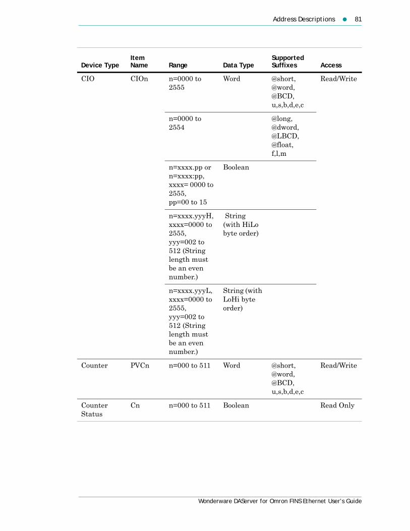
Address Descriptions 81
Wonderware DAServer for Omron FINS Ethernet User’s Guide
CIO CIOn n=0000 to 2555
Word @short,@word,@BCD,u,s,b,d,e,c
Read/Write
n=0000 to 2554
@long,@dword,@LBCD,@float, f,l,m
n=xxxx.pp or n=xxxx:pp, xxxx= 0000 to 2555,pp=00 to 15
Boolean
n=xxxx.yyyH, xxxx=0000 to 2555, yyy=002 to 512 (String length must be an even number.)
String (with HiLo byte order)
n=xxxx.yyyL, xxxx=0000 to 2555, yyy=002 to 512 (String length must be an even number.)
String (with LoHi byte order)
Counter PVCn n=000 to 511 Word @short,@word,@BCD, u,s,b,d,e,c
Read/Write
Counter Status
Cn n=000 to 511 Boolean Read Only
Device TypeItem Name Range Data Type
Supported Suffixes Access

82 Chapter 8 Item Reference Descriptions
Wonderware DAServer for Omron FINS Ethernet User’s Guide
CPU Bus Link
Gn n=000 to 255 Word @short,@word,@BCD,u,s,b,d,e,c
Read/Write
n=000 to 254 @long,@dword,@LBCD,@float, f,l,m
n=xxx.pp or n=xxx:pp, xxx=000 to 255, pp=00 to 15
Boolean
Device TypeItem Name Range Data Type
Supported Suffixes Access

Address Descriptions 83
Wonderware DAServer for Omron FINS Ethernet User’s Guide
Data Memory
Dn n=0000 to 8191
Word @short,@word,@BCD,u,s,b,d,e,c
Read/Write
n=0000 to 8190
@long,@dword,@LBCD,@float, f,l,m
n=xxxx.pp or n=xxxx:pp, xxxx= 0000 to 8191,pp=00 to 15
Boolean
n=xxxx.yyyH, xxxx = 0000 to 8191, yyy = 002 to 512(String length must be an even number.)
String (with HiLo byte order)
n=xxxx.yyyL, xxxx = 0000 to 8191, yyy = 002 to 512 (String length must be an even number.)
String (with LoHi byte order)
Data Register
DRn n=0 to 2 Word(arrays not supported)
Read/Write
Index Register
IRn n=0 to 2 Word(arrays not supported)
Read Only
Timer PVTn n=000 to 511 Word @short,@word,@BCD u,s,b,d,e,c
Read/Write
Device TypeItem Name Range Data Type
Supported Suffixes Access

84 Chapter 8 Item Reference Descriptions
Wonderware DAServer for Omron FINS Ethernet User’s Guide
CVM1-CPU11 Address DescriptionsModel CVM1-CPU11 supports the following types of devices.
Timer Status
Tn n=000 to 511 Boolean Read Only
Device TypeItem Name Range Data Type
Supported Suffixes Access
Device TypeItem Name Range Data Type
Supported Suffixes Access
Auxiliary Relay
An n=000 to 255 Word @short,@word,@BCD,u,s,b,d,e,c
Read/Write
n=000 to 254 @long,@dword,@LBCD,@float, f,l,m
n=256 to 511 Word @short,@word,@BCD,u,s,b,d,e,c
Read Only
n=256 to 510 @long,@dword,@LBCD,@float, f,l,m
n=xxx.pp or n=xxx:pp, xxx= 000 to 255,pp=00 to 15
Boolean Read/Write
n=xxx.pp, xxx=256 to 511,pp=00 to 15
Boolean Read Only

Address Descriptions 85
Wonderware DAServer for Omron FINS Ethernet User’s Guide
CIO CIOn n=0000 to 2555
Word @short,@word,@BCD,u,s,b,d,e,c
Read/Write
n=0000 to 2554
@long,@dword,@LBCD,@float, f,l,m
n=xxxx.pp or n=xxxx:pp, xxxx= 0000 to 2555,pp=00 to 15
Boolean
n=xxxx.yyyH xxxx=0000 to 2555, yyy=002 to 512(String length must be an even number.)
String (with HiLo byte order)
n=xxxx.yyyL xxxx=0000 to 2555, yyy=002 to 512(String length must be an even number.)
String (with LoHi byte order)
Counter PVCn n=000 to 1023 Word @short,@word,@BCD,u,s,b,d,e,c
Read/Write
Counter Status
Cn n=000 to 1023 Boolean Read Only
Device TypeItem Name Range Data Type
Supported Suffixes Access

86 Chapter 8 Item Reference Descriptions
Wonderware DAServer for Omron FINS Ethernet User’s Guide
CPU Bus Link
Gn n=000 to 255 Word @short,@word,@BCD,u,s,b,d,e,c
Read/Write
n=000 to 254 @long,@dword,@LBCD,@float, f,l,m
n=xxx.pp or n=xxx:pp, xxx= 000 to 255,pp=00 to 15
Boolean
Device TypeItem Name Range Data Type
Supported Suffixes Access

Address Descriptions 87
Wonderware DAServer for Omron FINS Ethernet User’s Guide
Data Memory Dn n=00000 to 24575
Word @short,@word,@BCD,u,s,b,d,e,c
Read/Write
n=00000 to 24574
@long,@dword,@LBCD,@float, f,l,m
n=xxxxx.pp or n=xxxxx:pp, xxxxx= 00000 to 24575, pp=00 to 15
Boolean
n=xxxx.yyyH, xxxx = 0000 to 24575, yyy = 002 to 512(String length must be an even number.)
String (with HiLo byte order)
n=xxxx.yyyL, xxxx = 0000 to 24575, yyy = 002 to 512(String length must be an even number.)
String (with LoHi byte order)
Data Register
DRn n=0 to 2 Word(arrays not supported)
Read/Write
Index Register
IRn n=0 to 2 Word Read Only
Timer PVTn n=000 to 1023 Word @short,@word,@BCD,u,s,b,d,e,c
Read/Write
Timer Status Tn n=000 to 1023 Boolean Read Only
Device TypeItem Name Range Data Type
Supported Suffixes Access

88 Chapter 8 Item Reference Descriptions
Wonderware DAServer for Omron FINS Ethernet User’s Guide
CVM1-CPU21 Address DescriptionsModel CVM1-CPU21 supports the following types of devices.
Device TypeItem Name Range Data Type
Supported Suffixes Access
Auxiliary Relay
An n=000 to 255 Word @short,@word,@BCD,u,s,b,d,e,c
Read/Write
n=000 to 254 @long,@dword,@LBCD,@float, f,l,m
n=256 to 511 Word @short,@word,@BCD,u,s,b,d,e,c
Read Only
n=256 to 510 @long,@dword,@LBCD,@float, f,l,m
n=xxx.pp or n=xxx:pp, xxx= 000 to 255, pp=00 to 15
Boolean Read/Write
n=xxx.pp or n=xxx:pp, xxx= 256 to 511, pp=00 to 15
Boolean Read Only

Address Descriptions 89
Wonderware DAServer for Omron FINS Ethernet User’s Guide
CIO CIOn n=0000 to 2555
Word @short,@word,@BCD, u,s, b,d,e,c
Read/Write
n=0000 to 2554
@long,@dword,@LBCD,@float, f,l,m
n=xxxx.pp or n=xxxx:pp, xxxx= 0000 to 2555, pp=00 to 15
Boolean
n=xxxx.yyyH,xxxx=0000 to 2555, yyy=002 to 512 (String length must be an even number.)
String (with HiLo byte order)
n=xxxx.yyyL,xxxx=0000 to 2555, yyy=002 to 512 (String length must be an even number.)
String (with LoHi byte order)
Counter PVCn n=0000 to 1023
Word @short,@word,@BCD,u,s,b,d,e,c
Read/Write
Counter Status
Cn n=000 to 1023 Boolean Read Only
Device TypeItem Name Range Data Type
Supported Suffixes Access

90 Chapter 8 Item Reference Descriptions
Wonderware DAServer for Omron FINS Ethernet User’s Guide
CPU Bus Link
Gn n=000 to 255 Word @short,@word,@BCD,u,s,b,d,e,c
Read/Write
n=000 to 254 @long,@dword,@LBCD,@float, f,l,m
n=xxx.pp or n=xxx:pp, xxx= 000 to 255, pp=00 to 15
Boolean
Device TypeItem Name Range Data Type
Supported Suffixes Access

Address Descriptions 91
Wonderware DAServer for Omron FINS Ethernet User’s Guide
Data Memory
Dn n=00000 to 24575
Word @short,@word,@BCD,u,s,b,d,e,c
Read/Write
n=00000 to 24574
@long,@dword,@LBCD,@float, f,l,m
n=xxxxx.pp or n=xxxxx:pp,xxxxx= 00000 to 24575, pp=00 to 15
Boolean
n=xxxx.yyyH, xxxx = 0000 to 24575, yyy = 002 to 512 (String length must be an even number.)
String (with HiLo byte order)
n=xxxx.yyyL, xxxx = 0000 to 24575, yyy = 002 to 512 (String length must be an even number.)
String (with LoHi byte order)
Data Register
DRn n=0 to 2 Word(arrays not supported)
Read/Write
Device TypeItem Name Range Data Type
Supported Suffixes Access

92 Chapter 8 Item Reference Descriptions
Wonderware DAServer for Omron FINS Ethernet User’s Guide
Expansion Data Memory (Current Bank)
En n=00000 to 32765
Word @short,@word,@BCD,u,s,b,d,e,c
Read/Write
n=00000 to 32764
@long,@dword,@LBCD,@float,f,l,m
n=xxxxx.pp or n=xxxxx:pp, xxxxx=00000 to 32765, pp=00 to 15
Boolean
n=xxxxx.yyyH, xxxxx=00000 to 32765, yyy=002 to 512 (String length must be an even number.)
String (with HiLo byte order)
n=xxxxx.yyyL, xxxxx=00000 to 32765, yyy=002 to 512 (String length must be an even number.)
String (with LoHi byte order)
Device TypeItem Name Range Data Type
Supported Suffixes Access

Address Descriptions 93
Wonderware DAServer for Omron FINS Ethernet User’s Guide
Expansion Data Memory
En n=zxxxxx, z =A to H, xxxxx=00000 to 32765
Word @short,@word,@BCD,u,s,b,d,e,c
Read/Write
n=zxxxxx, z =A to H, xxxxx=00000 to 32764
@long,@dword,@LBCD,@float, f,l,m
n=zxxxxx.pp or n=zxxxxx:pp, z =A to H, xxxxx=00000 to 32765, pp=00 to 15
Boolean
n=zxxxxx.yyyH, z =A to H, xxxxx=00000 to 32765, yyy=002 to 512 (String length must be an even number.)
String (with HiLo byte order)
n=zxxxxx.yyyL,z =A to H, xxxxx=00000 to 32765, yyy=002 to 512 (String length must be an even number.)
String (with LoHi byte order)
Index Register
IRn n=0 to 2 Word(arrays not supported)
Read Only
Device TypeItem Name Range Data Type
Supported Suffixes Access

94 Chapter 8 Item Reference Descriptions
Wonderware DAServer for Omron FINS Ethernet User’s Guide
Timer PVTn n=000 to 1023 Word @short,@word,@BCD, u,s,b,c,e,d
Read/Write
Timer Status Tn n=0000 to 1023
Boolean Read Only
Device TypeItem Name Range Data Type
Supported Suffixes Access

Address Descriptions 95
Wonderware DAServer for Omron FINS Ethernet User’s Guide
CS1 Address DescriptionsModel CS1 supports the following types of devices.
Note Expansion Data Memory in the CS1 Series PLC can be accessed using syntax EA, EB, EC...where EA refers to E0 memory area of the PLC, and so on. The range of the Expansion Data Memory depends upon the CPU type.
Device Type
Item Name Range Data Type
Supported Suffixes Access
Auxiliary Relay
An n=000 to 447 Word @short,@word,@BCD,u,s,b,d,e,c
Read Only
n=000 to 446 @long,@dword,@LBCD,@float, f,l,m
n=448 to 959 Word @short,@word,@BCD,u,s,b,d,e,c
Read/Write
n=448 to 958 @long,@dword,@LBCD,@float, f,l,m
n=xxx.pp or n=xxx:pp,xxxx= 000 to 447, pp=00 to 15
Boolean Read Only
n=xxx.pp or n=xxx:pp, xxx= 448 to 959, pp=00 to 15
Boolean Read/Write

96 Chapter 8 Item Reference Descriptions
Wonderware DAServer for Omron FINS Ethernet User’s Guide
CIO CIOn n=0000 to 6143 Word @short,@word,@BCD,u,s,b,d,e,c
Read/Write
n=0000 to 6142 @long,@dword,@LBCD,@float, f,l,m
n=xxxx.pp or n=xxxx:pp, xxxx= 0000 to 6143,pp=00 to 15
Boolean
n=xxxx.yyyH, xxxx=0000 to 6143, yyy=002 to 512 (String length must be an even number.)
String (with HiLo byte order)
n=xxxx.yyyL, xxxx=0000 to 6143, yyy=002 to 512 (String length must be an even number.)
String (with LoHi byte order)
Counter PVCn n=0000 to 4095 Word @short,@word,@BCD, u,s,b,d,e,c
Read/Write
Counter Status
Cn n=0000 to 4095 Boolean Read Only
Device Type
Item Name Range Data Type
Supported Suffixes Access

Address Descriptions 97
Wonderware DAServer for Omron FINS Ethernet User’s Guide
Data Memory
Dn n=00000 to 32767 Word @short,@word,@BCD,u,s,b,d,e,c
Read/Write
n=00000 to 32766 @long,@dword,@LBCD,@float, f,l,m
n=xxxxx.pp or n=xxxxx:pp,xxxxx=00000 to 32767, pp=00 to 15
Boolean
n=xxxxx.yyyH xxxxx = 00000 to 32767, yyy = 002 to 512 (String length must be an even number.)
String (with HiLo byte order)
n=xxxxx.yyyL xxxxx = 00000 to 32767, yyy = 002 to 512 (String length must be an even number.)
String (with LoHi byte order)
Data Register
DRn n=00 to 15 Word(arrays not supported)
@short,@word,@BCD, u,s,b
Read/Write*
n=00 to 14 @long,@dword,@LBCD,@float, f,l,m
Device Type
Item Name Range Data Type
Supported Suffixes Access

98 Chapter 8 Item Reference Descriptions
Wonderware DAServer for Omron FINS Ethernet User’s Guide
Expansion Data Memory (current bank)
En n=00000 to 32767 Word @short,@word,@BCD,u,s,b,d,e,c
Read/Write
n=00000 to 32766 @long,@dword,@LBCD,@float, f,l,m
n=xxxxx.pp or n=xxxxx:pp, xxxxx=00000 to 32767, pp=00 to 15
Boolean
n=xxxxx.yyyH, xxxxx=00000 to 32767, yyy=002 to 512 (String length must be an even number.)
String (with HiLo byte orde )
n=xxxxx.yyyL, xxxxx=00000 to 32767, yyy=002 to 512 (String length must be an even number.)
String (with LoHi byte order)
Device Type
Item Name Range Data Type
Supported Suffixes Access

Address Descriptions 99
Wonderware DAServer for Omron FINS Ethernet User’s Guide
Expansion Data Memory
En n=zxxxxx ,z =A to M, xxxxx=00000 to 32767
Word @short,@word,@BCD,u,s,b,d,e,c
Read/Write
n=zxxxxx,z =A to M, xxxxx=00000 to 32766
@long,@dword,@LBCD,@float, f,l,m
n=zxxxxx.pp or n=zxxxxx:pp, z =A to M, xxxxx=00000 to 32767, pp=00 to 15
Boolean
n=zxxxxx.yyyH, z =A to M, xxxxx=00000 to 32767, yyy=002 to 512 (String length must be an even number.)
String (with HiLo byte order)
n=zxxxxx.yyyL, z =A to M, xxxxx=00000 to 32767,yyy=002 to 512 (String length must be an even number.)
String (with LoHi byte order)
Device Type
Item Name Range Data Type
Supported Suffixes Access

100 Chapter 8 Item Reference Descriptions
Wonderware DAServer for Omron FINS Ethernet User’s Guide
Holding Relay
Hn n=0000 to 1535 Word @short,@word,@BCD,u,s,b,d,e,c
Read/Write
n=0000 to 1534 @long,@dword,@LBCD,@float, f,l,m
n=xxxx.pp or n=xxxx:pp, xxxx= 0000 to 1535, pp=00 to 15
Boolean
Index Register
IRn n=00 to 15 Long(arrays not supported)
m Read/Write*
Task Flag TKn n=00 to 31 Boolean Read Only
Timer PVTn n=0000 to 4095 Word @short,@word,@BCD, u,s,b,d,e,c
Read/Write
Timer Status
Tn n=0000 to 4095 Boolean Read Only
Working Relay
Wn n=000 to 511 Word @short,@word,@BCD,u,s,b,d,e,c
Read/Write
n=000 to 510 @long,@dword,@LBCD,@float, f,l,m
n=xxx:pp or n=xxx:pp,xxx=000 to 511 pp=00 to 15
Boolean
Device Type
Item Name Range Data Type
Supported Suffixes Access

Address Descriptions 101
Wonderware DAServer for Omron FINS Ethernet User’s Guide
* IR and DR registers can only be written to when the device is in programming mode. If the device is in Run Mode and a write is attempted to a DR or IR register, the write appears to succeed in DAServer diagnostics. However the value is not changed in the device and no message is logged in the Logger.
CJ1 Address DescriptionsModel CJ1 supports the following types of devices.
Note Expansion Data Memory in the CJ1 Series PLC can be accessed using syntax EA, EB, EC...where EA refers to E0 memory area of the PLC, and so on. The range of the Expansion Data Memory depends upon the CPU type.
Device Type
Item Name Range Data Type
Supported Suffixes Access
Auxiliary Relay
An n=000 to 447 Word @short,@word,@BCD,u,s,b,d,e,c
Read Only
n=000 to 446 @long,@dword,@LBCD,@float,f,l,m
n=448 to 959 Word @short,@word,@BCD,u,s,b,d,e,c
Read/Write
n=448 to 958 @long,@dword,@LBCD,@float,f,l,m
n=xxx.pp or n=xxx:pp,xxx= 000 to 447, pp=00 to 15
Boolean Read Only
n=xxx.pp or n=xxx:pp, xxx= 448 to 959, pp=00 to 15
Boolean Read/Write

102 Chapter 8 Item Reference Descriptions
Wonderware DAServer for Omron FINS Ethernet User’s Guide
CIO CIOn n=0000 to 6143 Word @short,@word,@BCD,u,s,b,d,e,c
Read/Write
n=0000 to 6142 @long,@dword,@LBCD,@float,f,l,m
n=xxxx.pp or n=xxxx:pp, xxxx= 0000 to 6143, pp=00 to 15
Boolean
n=xxxx.yyyH, xxxx=0000 to 6143, yyy=002 to 512 (String length must be an even number.)
String (with HiLo byte order)
n=xxxx.yyyL, xxxx=0000 to 6143, yyy=002 to 512 (String length must be an even number.)
String (with LoHi byte order)
Counter PVCn n=0000 to 4095 Word @short,@word,@BCD,u,s,b,d,e,c
Read/Write
Counter Status
Cn n=0000 to 4095 Boolean Read Only
Device Type
Item Name Range Data Type
Supported Suffixes Access

Address Descriptions 103
Wonderware DAServer for Omron FINS Ethernet User’s Guide
Data Memory
Dn n=00000 to 32767 Word @short,@word,@BCD, u,s,b,d,e,c
Read/Write
n=00000 to 32766 @long,@dword,@LBCD,@float,f,l,m
n=xxxxx.pp or n=xxxxx:pp, xxxxx=00000 to 32767, pp=00 to 15
Boolean
n=xxxxx.yyyH xxxxx = 00000 to 32767, yyy = 002 to 512 (String length must be an even number.)
String (with HiLo byte order)
n=xxxxx.yyyL xxxxx = 00000 to 32767, yyy = 002 to 512(String length must be an even number.
String (with LoHi byte order)
Data Register
DRn n=00 to 15 Word @short,@word,@BCD,u,s,b
Read/Write*
n=00 to 14 @long,@dword,@LBCD,@float,f,l,m
Device Type
Item Name Range Data Type
Supported Suffixes Access

104 Chapter 8 Item Reference Descriptions
Wonderware DAServer for Omron FINS Ethernet User’s Guide
Expansion Data Memory (current bank)
En n=00000 to 32767 Word @short,@word,@BCD,u,s,b,d,e,c
Read/Write
n=00000 to 32766 @long,@dword,@LBCD,@float,f,l,m
n=xxxxx.pp or n=xxxxx:pp, xxxxx=00000 to 32767,pp=00 to 15
Boolean
n=xxxxx.yyyH, xxxxx=00000 to 32767,yyy=002 to 512 (String length must be an even number.)
String (with HiLo byte order)
n=xxxxx.yyyL, xxxxx=00000 to 32767, yyy=002 to 512 (String length must be an even number.)
String (with LoHi byte order)
Device Type
Item Name Range Data Type
Supported Suffixes Access
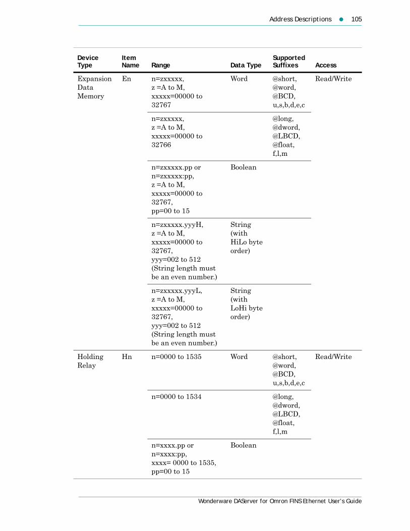
Address Descriptions 105
Wonderware DAServer for Omron FINS Ethernet User’s Guide
Expansion Data Memory
En n=zxxxxx, z =A to M, xxxxx=00000 to 32767
Word @short,@word,@BCD,u,s,b,d,e,c
Read/Write
n=zxxxxx, z =A to M, xxxxx=00000 to 32766
@long,@dword,@LBCD,@float,f,l,m
n=zxxxxx.pp or n=zxxxxx:pp, z =A to M, xxxxx=00000 to 32767, pp=00 to 15
Boolean
n=zxxxxx.yyyH, z =A to M, xxxxx=00000 to 32767, yyy=002 to 512 (String length must be an even number.)
String (with HiLo byte order)
n=zxxxxx.yyyL, z =A to M, xxxxx=00000 to 32767, yyy=002 to 512 (String length must be an even number.)
String (with LoHi byte order)
Holding Relay
Hn n=0000 to 1535 Word @short,@word,@BCD,u,s,b,d,e,c
Read/Write
n=0000 to 1534 @long,@dword,@LBCD,@float,f,l,m
n=xxxx.pp or n=xxxx:pp, xxxx= 0000 to 1535, pp=00 to 15
Boolean
Device Type
Item Name Range Data Type
Supported Suffixes Access

106 Chapter 8 Item Reference Descriptions
Wonderware DAServer for Omron FINS Ethernet User’s Guide
* IR and DR registers can only be written to when the device is in programming mode. If the device is in Run Mode and a write is attempted to a DR or IR register, the write appears to succeed in DAServer diagnostics. However the value is not changed in the device and no message is logged in the Logger.
Index Register
IRn n=00 to 15 Long m Read/Write*
Task Flag TKn n=00 to 31 Boolean Read Only
Timer PVTn n=0000 to 4095 Word @short,@word,@BCD,u,s,b,d,e,c
Read/Write
Timer Status
Tn n=0000 to 4095 Boolean Read Only
Working Relay
Wn n=000 to 511 Word @short,@word,@BCD,u,s,b,d,e,c
Read/Write
n=000 to 510 @long,@dword,@LBCD,@float,f,l,m
n=xxx:pp or n=xxx:pp, xxx=000 to 511 pp=00 to 15
Boolean
Device Type
Item Name Range Data Type
Supported Suffixes Access

107
Wonderware DAServer for Omron FINS Ethernet User’s Guide
Chapter 9
Troubleshooting
You can troubleshoot problems with the DAServer using the:
• Windows Task Manager
• Windows Performance and Alerts (PerfMon) application also called Performance Monitor
• DAServer Manager
• ArchestrA Log Flag Editor
• ArchestrA Log Viewer
Your client application may let you view error messages, monitor the status of requests, and allow you to request data on the status of the DAServer and connected devices. For more information, see your client application documentation.
Troubleshooting with Windows ToolsWindows has two tools that may be useful in troubleshooting performance problems.
You can find quick verification that the DAServer process is running by looking at the Windows Task Manager. It also provides information on the user, CPU, and memory usage of the processes.
If you need more information, or need to gather data while not logged in, you can use the Performance and Alerts application. For more information, see the Microsoft Management Console (MMC) help files on the Performance application. The Performance application is one of the administrative tools found in the Windows Control Panel.

108 Chapter 9 Troubleshooting
Wonderware DAServer for Omron FINS Ethernet User’s Guide
Troubleshooting with the DAServer ManagerThe DAServer Manager has information that may be useful in troubleshooting problems. When the DAServer is active, a diagnostic node is present below the configuration node in the console tree of the System Management Console.
Each diagnostic leaf contains information about DAServer activity. For more information, see the DAServer Manager User Guide or Help files.
Finding Version InformationIf you contact Technical Support, you may need to supply version information.
To determine the DAServer Manager version
In the DAServer Manager, right-click DAServer Manager, and then click About DAServer Manager. An About box appears showing the version and build date of the DAServer Manager.
To determine version information for DAServer components
In the DAServer Manager, select the DAServer name in the console tree. The version information for each DAServer component is shown in the details pane.
Using the Wonderware Log ViewerError messages are created by the DAServer and logged by the Logger. You can view these messages with the Log Viewer. The Log Viewer help files explain how to view messages and how to filter which messages are shown.
Log Flags are categories of messages. The Log Flag Editor User Guide contains an explanation of the categories. Using the Log Flag Editor, you can specify which log flags the DAServer creates.
Note Generating large numbers of diagnostic messages can impact DAServer performance. You should not run in production with any more flags than those set when the DAServer is installed. To troubleshoot you can turn on more flags, but there is a performance impact. For more information, see the Log Flag Editor User Guide.
Using the Wonderware Log Viewer 109
Wonderware DAServer for Omron FINS Ethernet User’s Guide
To open the Log Flag Editor
1 In the System Management Console, expand Log Viewer and then expand the log viewer group.
2 Select Local.
3 On the Action menu, click Log Flags.In general, look at error and warning messages to determine if a problem exists. To determine whether the DAServer is communicating with a device, you can enable the DASSend and DASReceive log flags. From these you can determine whether or not the device is responding.
Basic Log FlagsThe basic log flags for all ArchestrA components are:
• Error: A fatal error, the program cannot continue. By default set on by logger.
• Warning: The error is recoverable. A client called with a bad parameter, or the result of some operation was incorrect, but the program can continue. By default set on by logger.
• Start-Stop: Each main component logs a message to this category as it starts and stops.
• Info: General diagnostic messages.
• Ctor-Dtor: C++ classes of interest log messages to this category as they are constructed and destructed.
• Entry-Exit: Functions of interest log messages to this category as they are called and return.
• Thread Start-Stop: All threads should log messages to this category as they start and stop.

110 Chapter 9 Troubleshooting
Wonderware DAServer for Omron FINS Ethernet User’s Guide
DAServer Log FlagsMessages created for these log flags are for DAServer common components and contain information about internal DAServer activities.
• DACmnProtFail: Some failure occurred in the common components while sending a message, updating an item, or otherwise moving data. Typically, this represents some unexpected behavior in the server-specific DLL.
• DACmnProtWarn: Some problem occurred that interfered with sending messages, updating items, or otherwise moving data. Common examples are slow poll, value limiting during type conversion, and transaction timeout messages.
• DACmnTrace: Normal processing of client program requests and data movement to and from the server-specific DLL are traced on this log flag. Use this in conjunction with DACmnVerbose to get the most information.
• DACmnVerbose: Many log flags used by the DAS common components are modified occasionally by DACmnVerbose. When DACmnVerbose is set, the logging of messages on other log flags includes more information.
• DACmnSend: Operations within the DAS Engine DLL that revolve around sending messages to the server-specific DLL.
• DACmnReceive: Events surrounding messages that are returned to the DAS Engine by the server-specific DLL, including the blocking and unblocking of hierarchies.

Using the Wonderware Log Viewer 111
Wonderware DAServer for Omron FINS Ethernet User’s Guide
DAServer-Device Interface Log FlagsMessages created for the following log flags are specific to an individual DAServer and contain information about communications between the DAServer and device.
• DASProtFail: An error in the protocol occurred, for example, device disconnected. The program can continue, and, in fact, this category is expected during normal operation of the program. Must be set on by the generic DAS code when the DAServer starts.
• DASProtWarn: Something unexpected occurred in the protocol, for example, a requested item with an otherwise valid item name is not supported by this device. Must be set on by the generic DAS code when the DAServer starts.
• DASTrace: General diagnostic messages of a protocol-specific nature. For example, you can provide the number of items in a message for a specific protocol, then optimize based on the number.
• DASVerbose: Modifies all other DAS logging flags. When on, provides detailed messages.
• DASSend: Protocol messages sent to the device are logged to this category.
• DASReceive: Protocol messages received from the device are logged to this category.
• DASStateCat1, DASStateCat2, DASStateCat3, DASStateCat4: These are general categories for use by the server developer. As DeviceEngine-generated state machines are created by the DAServer, they can be told to log state machine messages to one of the following: DASStateCat1, DASStateCat2, DASStateCat3, or DASStateCat4. These messages indicate when a state is made the active state, when a state handler is run, when a state handler completes, and when a timeout occurs for a state machine.
• DASStateMachine: By default, DeviceEngine-generated state machines created by the DAServer log to this category unless specifically told to log to one of the DASStateCatN categories. In addition, general state machine messages are logged to this category. These messages indicate when a state machine is created and deleted.

112 Chapter 9 Troubleshooting
Wonderware DAServer for Omron FINS Ethernet User’s Guide
Error Message DescriptionsThese messages are specific to the Wonderware DAServer for Omron Fins Ethernet. When you enable the specified log flag, these messages are generated and logged.
Message Log Flag Possible Cause Solution
Missing address Warning A tag address has no length. Re-enter the address in the client application.
Device address '<address>' contains a syntax error.
Warning A tag address contains one or more invalid characters.
Re-enter the address in the client application.
Address '<address>' is out of range for the specified device or register.
Warning A tag address references a location that is beyond the range of supported locations for the device.
Verify that the address is correct. If the address is incorrect, re-enter it in the client application.
Device address '<address>' is not supported by model '<model name>.’
Warning A tag address references a location that is valid for the communications protocol but not supported by the target device.
Verify that the address is correct. If the address is incorrect, re-enter it in the client application. Verify that the selected model name for the device is correct.
Data Type '<type>' is not valid for device address '<address>'
Warning A tag address has been assigned an invalid data type.
Modify the requested data type in the client application.
Device address '<address>' is read-only.
Warning A tag address has a requested access mode that is not compatible with what the device supports for that address.
Change the access mode in the client application.
Winsock V1.1 or higher must be installed to use the Omron FINS Ethernet device driver
Error The version number of the Winsock DLL found on your system is less than 1.1.
Upgrade your version of Winsock to 1.1 or higher.

Error Message Descriptions 113
Wonderware DAServer for Omron FINS Ethernet User’s Guide
Device '<device name>' is not responding.
Error 1. The connection between the device and the host PC is broken.
2. The IP address assigned to the device is incorrect.
3. The named device may have been assigned an incorrect network ID.
1. Verify the cabling between the PC and the PLC device.
2. Verify that the IP address given to the named device matches that of the actual device.
3. Verify that the network ID given to the named device matches that of the actual device.
Unable to write to '<address>' on device '<device name>.'
Error 1. The connection between the device and the host PC is broken.
2. The named device may have been assigned an incorrect IP address.
3. The named device may have been assigned an incorrect network ID.
1. Verify the cabling between the PC and the PLC device.
2. Verify that the IP address given to the named device matches that of the actual device.
3. Verify that the network ID given to the named device matches that of the actual device.
Device '<device name>' responded with local node error.
Error The named device may have been assigned an incorrect network ID.
Verify that the network ID given to the named device matches that of the actual device.
Device '<device name>' responded with destination node error.
Error The named device may have been assigned an incorrect network ID.
Verify that the network ID given to the named device matches that of the actual device.
Device '<device name>' responded with a communications error.
Error The named device may have been assigned an incorrect network ID.
Verify that the network ID given to the named device matches that of the actual device.
Message Log Flag Possible Cause Solution

114 Chapter 9 Troubleshooting
Wonderware DAServer for Omron FINS Ethernet User’s Guide
Device '<device name>' cannot process command (Tag '<address>', Size '<bytes>').
Warning Named device cannot process command for specified model.
Verify that the correct model number is assigned to the device.
Device '<device name>' responded with routing table error.
Error The named device may have been assigned an incorrect network ID.
Verify that the network ID given to the named device matches that of the actual device.
Device '<device name>' responded with a command format error (Tag '<address>', Size '<bytes>').
Warning 1. The local node's relay table or relay node's local network table is wrong.
2. Incorrect command format has been used.
1. Verify routing table settings in the network devices.
2. Verify that the correct model number is assigned to the device.
Device '<device name>' responded with a command parameter error (Tag '<address>', Size '<bytes>').
Warning Requested memory code area is not available.
Check for availability of the referenced address (i.e. existence of Expansion Data Memory).
Device '<device name>' responded with error in unit.
Error CPU bus error or memory error in named device.
Check the unit for error indicator and attempt to clear errors.
Device '<device name>' cannot accept command (Tag '<address>', Size '<bytes>').
Warning Too many commands are at the destination node.
Wait for servicing to complete and re-execute command.
Device '<device name>' access right denied (Tag '<address>').
Warning The access right is held by another device.
Release access right and re-execute command.
Message Log Flag Possible Cause Solution
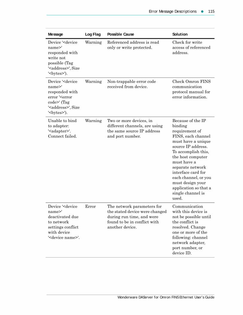
Error Message Descriptions 115
Wonderware DAServer for Omron FINS Ethernet User’s Guide
Device '<device name>' responded with write not possible (Tag '<address>', Size '<bytes>').
Warning Referenced address is read only or write protected.
Check for write access of referenced address.
Device '<device name>' responded with error '<error code>' (Tag '<address>', Size '<bytes>').
Warning Non-trappable error code received from device.
Check Omron FINS communication protocol manual for error information.
Unable to bind to adapter: '<adapter>'. Connect failed.
Warning Two or more devices, in different channels, are using the same source IP address and port number.
Because of the IP binding requirement of FINS, each channel must have a unique source IP address. To accomplish this, the host computer must have a separate network interface card for each channel, or you must design your application so that a single channel is used.
Device '<device name>' deactivated due to network settings conflict with device '<device name>'.
Error The network parameters for the stated device were changed during run time, and were found to be in conflict with another device.
Communication with this device is not be possible until the conflict is resolved. Change one or more of the following: channel network adapter, port number, or device ID.
Message Log Flag Possible Cause Solution

116 Chapter 9 Troubleshooting
Wonderware DAServer for Omron FINS Ethernet User’s Guide
Unable to write to register <register address> for device <device name>. The device is in run mode.
Warning The device is in run mode. CS and TS registers can only be written to when the device is in programming mode.
Set the device to programming mode.
Message Log Flag Possible Cause Solution

117
Wonderware DAServer for Omron FINS Ethernet User’s Guide
Index
Symbols$SYS$Status 50
Numerics32-bit values, using 63
Aactivate 44adapter 19address descriptions 64array support 63
BBCD support 60bit access 63
CC200 address descriptions 64channel
adding 18deleting 21renaming 18setting parameters 18
CJ1 address descriptions 101communication timeouts 26
connect timeout 26fail after 26reply timeout 26
communications port 19configuration sets
archiving 43changing parameters 43clearing 44deleting 44selecting 43
configureas a service 42not a service 42
Connect timeout 26CS1 addres descriptions 95CV1000 address descriptions 74CV2000 address descriptions 74CV500 address descriptions 70CVM1-CPU01 address descriptions 80CVM1-CPU11 address descriptions 84CVM1-CPU21 address descriptions 88
DDAServer Manager 9, 15
troubleshooting 108DASReceive 111DASSend 111data types
definition 59supported 58
DDE/SuiteLink

118 Index
Wonderware DAServer for Omron FINS Ethernet User’s Guide
$SYS$STATUS 50accessing data using 48configure as a service 42device groups 31topic 48
deactivate 45demo mode 46device groups 31, 49
adding 31deleting 34renaming 32setting data 33update interval 33
device items 35clearing all 39definition 35deleting 37renaming 37setting the name 36
devicesadding 23deleting 30renaming 24setting options 27setting parameters 24setting the model 24
duty cycle 20
Eerror descriptions 112error log flag 109export 38
Ffail after 26FINS
network configuration 28firewall 12floating point format support 60
Iimporting 39in-proc 45item reference 35
access 59data type 59device type 59format and syntax 59
memory access 60range 59setting 38supported data types 58
LLog Flag Editor 108log flags 108
DASReceive 111DASSend 111error 109warning 109
Log Viewer 10long format support 60
OOPC
$SYS$STATUS 50accessing data using 48browsable items 35device groups 31supported protocols 10
out-of-proc 45
Pports
setting 19
Rreply timeout 26request size, setting 27
Sservice
configuring as 42configuring not as a 42
string support 61SuiteLink
address fields 48supported protocols 10
system items 10, 35, 49
Ttime out 26troubleshooting 10, 107, 108
Log Flag Editor 108Log Viewer 108version information 108

Index 119
Wonderware DAServer for Omron FINS Ethernet User’s Guide
Uupdate interval 31, 33
Vversion information 108
Wwarning log flag 109

120 Index
Wonderware DAServer for Omron FINS Ethernet User’s Guide


