OIML R 50-2 (E), Edition 1997 - TSAPPS at NIST STANDARD DRAFT SASO OIML R 50-2: 2011 OIML R 50-2:...
59
SAUDI STANDARD DRAFT SASO OIML R 50-2: 2011 OIML R 50-2: 1997 Continuous totalizing automatic weighing instruments (belt weighers) Part 2: Test report format SAUDI ARABIAN STANDARDS ORGANI ZA TI ON THIS DOCUMENT IS A DRAFT SAUDI STANDARD CIRCULATED FOR COMMENT. IT IS, THEREFORE SUBJECT TO CHANGE AND MAY NOT BE REFERRED TO AS A SAUDI STANDARD UNTIL APPROVED BY THE BOARD OF DIRECTORS.
-
Upload
nguyenngoc -
Category
Documents
-
view
225 -
download
4
Transcript of OIML R 50-2 (E), Edition 1997 - TSAPPS at NIST STANDARD DRAFT SASO OIML R 50-2: 2011 OIML R 50-2:...
SAUDI STANDARD
DRAFT
SASO OIML R 50-2: 2011
OIML R 50-2: 1997
Continuous totalizing automatic weighing instruments (belt weighers)
Part 2: Test report format
SAUDI ARABIAN STANDARDS ORGANIZATION
THIS DOCUMENT IS A DRAFT SAUDI STANDARD CIRCULATED FOR
COMMENT. IT IS, THEREFORE SUBJECT TO CHANGE AND MAY NOT
BE REFERRED TO AS A SAUDI STANDARD UNTIL APPROVED BY THE
BOARD OF DIRECTORS.
- R 50-2 page 2
SAUDI STANDARD SASO OIML R 50-2/2011
CONTENTS
Foreword . . . . . . . . . . . . . . . . . . . . . . . . . . . . . . . . . . . . . . . . . . . . . . . . . . . . . . . . . . . . . . . . . . . . . . . . . . . . . . . . . . . . . . . . . 3
Introduction . . . . . . . . . . . . . . . . . . . . . . . . . . . . . . . . . . . . . . . . . . . . . . . . . . . . . . . . . . . . . . . . . . . . . . . . . . . . . . . . . . . . . . . 4
Identification of the instrument . . . . . . . . . . . . . . . . . . . . . . . . . . . . . . . . . . . . . . . . . . . . . . . . . . . . . . . . . . . . . . . . . . . . . . . . . 5
General information concerning the pattern . . . . . . . . . . . . . . . . . . . . . . . . . . . . . . . . . . . . . . . . . . . . . . . . . . . . . . . . . . . . . . . 7
Checklist . . . . . . . . . . . . . . . . . . . . . . . . . . . . . . . . . . . . . . . . . . . . . . . . . . . . . . . . . . . . . . . . . . . . . . . . . . . . . . . . . . . . . . . . . 10
Summary of the checklist . . . . . . . . . . . . . . . . . . . . . . . . . . . . . . . . . . . . . . . . . . . . . . . . . . . . . . . . . . . . . . . . . . . . . . . . . 10
Checklist . . . . . . . . . . . . . . . . . . . . . . . . . . . . . . . . . . . . . . . . . . . . . . . . . . . . . . . . . . . . . . . . . . . . . . . . . . . . . . . . . . . . . . 12
Test report
Test equipment used for pattern evaluation . . . . . . . . . . . . . . . . . . . . . . . . . . . . . . . . . . . . . . . . . . . . . . . . . . . . . . . . . . . . 23
Configuration for test . . . . . . . . . . . . . . . . . . . . . . . . . . . . . . . . . . . . . . . . . . . . . . . . . . . . . . . . . . . . . . . . . . . . . . . . . . . . 24
Explanatory notes . . . . . . . . . . . . . . . . . . . . . . . . . . . . . . . . . . . . . . . . . . . . . . . . . . . . . . . . . . . . . . . . . . . . . . . . . . . . . . . 25
Summary of test report . . . . . . . . . . . . . . . . . . . . . . . . . . . . . . . . . . . . . . . . . . . . . . . . . . . . . . . . . . . . . . . . . . . . . . . . . . . 26
1 Simulation tests . . . . . . . . . . . . . . . . . . . . . . . . . . . . . . . . . . . . . . . . . . . . . . . . . . . . . . . . . . . . . . . . . . . . . . . . . . . . . 27
Simulator data
1.1 Warm-up time . . . . . . . . . . . . . . . . . . . . . . . . . . . . . . . . . . . . . . . . . . . . . . . . . . . . . . . . . . . . . . . . . . . . . . . . . . . . . . 28
1.2 Variation of simulation speed . . . . . . . . . . . . . . . . . . . . . . . . . . . . . . . . . . . . . . . . . . . . . . . . . . . . . . . . . . . . . . . . . . 29
1.3 Eccentric loading . . . . . . . . . . . . . . . . . . . . . . . . . . . . . . . . . . . . . . . . . . . . . . . . . . . . . . . . . . . . . . . . . . . . . . . . . . . . 30
1.4 Zero-setting device . . . . . . . . . . . . . . . . . . . . . . . . . . . . . . . . . . . . . . . . . . . . . . . . . . . . . . . . . . . . . . . . . . . . . . . . . . . 31
1.4.1 Zero-setting (range) . . . . . . . . . . . . . . . . . . . . . . . . . . . . . . . . . . . . . . . . . . . . . . . . . . . . . . . . . . . . . . . . . . . . . . . . . . 31
1.4.2 Zero-setting (semi-automatic and automatic) . . . . . . . . . . . . . . . . . . . . . . . . . . . . . . . . . . . . . . . . . . . . . . . . . . . . . . 32
1.5 Influence quantities . . . . . . . . . . . . . . . . . . . . . . . . . . . . . . . . . . . . . . . . . . . . . . . . . . . . . . . . . . . . . . . . . . . . . . . . . . 33
1.5.1 Static temperatures . . . . . . . . . . . . . . . . . . . . . . . . . . . . . . . . . . . . . . . . . . . . . . . . . . . . . . . . . . . . . . . . . . . . . . . . . . . 33
1.5.2 Temperature effect at zero flowrate . . . . . . . . . . . . . . . . . . . . . . . . . . . . . . . . . . . . . . . . . . . . . . . . . . . . . . . . . . . . . . 37
1.5.3 Damp heat, steady state . . . . . . . . . . . . . . . . . . . . . . . . . . . . . . . . . . . . . . . . . . . . . . . . . . . . . . . . . . . . . . . . . . . . . . . 38
1.5.4 Mains power supply (AC) . . . . . . . . . . . . . . . . . . . . . . . . . . . . . . . . . . . . . . . . . . . . . . . . . . . . . . . . . . . . . . . . . . . . . 40
1.5.5 Battery power supply (DC) . . . . . . . . . . . . . . . . . . . . . . . . . . . . . . . . . . . . . . . . . . . . . . . . . . . . . . . . . . . . . . . . . . . . 42
1.6 Disturbances . . . . . . . . . . . . . . . . . . . . . . . . . . . . . . . . . . . . . . . . . . . . . . . . . . . . . . . . . . . . . . . . . . . . . . . . . . . . . . . 43
1.6.1 Voltage dips and short interruptions . . . . . . . . . . . . . . . . . . . . . . . . . . . . . . . . . . . . . . . . . . . . . . . . . . . . . . . . . . . . . 43
1.6.2 Electrical fast transients/burst immunity . . . . . . . . . . . . . . . . . . . . . . . . . . . . . . . . . . . . . . . . . . . . . . . . . . . . . . . . . . 44
1.6.3 Electrostatic discharges . . . . . . . . . . . . . . . . . . . . . . . . . . . . . . . . . . . . . . . . . . . . . . . . . . . . . . . . . . . . . . . . . . . . . . . 46
1.6.4 Electromagnetic susceptibility . . . . . . . . . . . . . . . . . . . . . . . . . . . . . . . . . . . . . . . . . . . . . . . . . . . . . . . . . . . . . . . . . . 49
1.7 Metrological characteristics . . . . . . . . . . . . . . . . . . . . . . . . . . . . . . . . . . . . . . . . . . . . . . . . . . . . . . . . . . . . . . . . . . . . 50
1.7.1 Repeatability . . . . . . . . . . . . . . . . . . . . . . . . . . . . . . . . . . . . . . . . . . . . . . . . . . . . . . . . . . . . . . . . . . . . . . . . . . . . . . . 50
1.7.2 Discrimination of the totalization indicating device . . . . . . . . . . . . . . . . . . . . . . . . . . . . . . . . . . . . . . . . . . . . . . . . . . 51
1.7.3 Discrimination of the totalization indicating device used for zero totalization . . . . . . . . . . . . . . . . . . . . . . . . . . . . . . 52
1.7.4 Short- and long-term stability of zero . . . . . . . . . . . . . . . . . . . . . . . . . . . . . . . . . . . . . . . . . . . . . . . . . . . . . . . . . . . . 53
1.8 In-situ tests . . . . . . . . . . . . . . . . . . . . . . . . . . . . . . . . . . . . . . . . . . . . . . . . . . . . . . . . . . . . . . . . . . . . . . . . . . . . . . . . 54
1.8.1 Maximum permissible errors on checking of zero . . . . . . . . . . . . . . . . . . . . . . . . . . . . . . . . . . . . . . . . . . . . . . . . . . . 55
1.8.2 Discrimination of the indicator used for zero setting . . . . . . . . . . . . . . . . . . . . . . . . . . . . . . . . . . . . . . . . . . . . . . . . . 56
2 In-situ material tests . . . . . . . . . . . . . . . . . . . . . . . . . . . . . . . . . . . . . . . . . . . . . . . . . . . . . . . . . . . . . . . . . . . . . . . . . 57
2.1 Accuracy of control instrument . . . . . . . . . . . . . . . . . . . . . . . . . . . . . . . . . . . . . . . . . . . . . . . . . . . . . . . . . . . . . . . . . 57
2.2 Repeatability . . . . . . . . . . . . . . . . . . . . . . . . . . . . . . . . . . . . . . . . . . . . . . . . . . . . . . . . . . . . . . . . . . . . . . . . . . . . . . . 58

SAUDI STANDARD SASO OIML R 50-2/2011
Foreword
The Saudi Arabian Standards Organization (SASO) has adopted the International
standard No. OIML R 50-2/1997 “Continuous totalizing automatic weighing
instruments (belt weighers)- Part 2: Test report format ” issued by the OIML. The
text of this international standard has been translated into Arabic so as to be
approved as a Saudi standard without introducing any technical modification.
1
- R 50-2 page 4 -
INTRODUCTION
The “Test report format”, the subject of OIML R 50-2, aims at presenting, in a standardized format, the results
of the various tests and examinations to which a pattern of a continuous totalizing automatic weighing instrument
(belt weigher) shall be submitted with a view to its approval.
The “Test report format” consists of two parts, the “Checklist” and the “Test report”.
The “Checklist” is a summary of the examinations carried out on the instrument. It includes the conclusions of
the results of the tests performed, experimental or visual checks based on the requirements of OIML R 50-1.
The words or condensed sentences aim at reminding the examiner of the requirements of R 50-1 without
reproducing them.
The “Test report” is a record of the results of the tests carried out on the instrument. The “Test report” forms
have been produced based on the tests detailed in the test procedures (Annex A of OIML R 50-1).
The “information concerning the test equipment used for pattern evaluation” shall cover all test equipment
which has been used in determining the test results given in a report. The information may be a short list
containing essential data (name, type, reference number for purpose of traceability). For example:
• Verification standards (accuracy or accuracy class, and No.);
• Simulator for testing of modules (name, type, traceability and No.);
• Climatic test and static temperature chamber (name, type and No.);
• Electrical tests, bursts (name of the instrument, type and No.);
• Description of the procedure of field calibration for the test of electromagnetic susceptibility.
All metrology services or laboratories evaluating patterns of continuous totalizing automatic weighing
instruments according to OIML R 50-1 or to national or regional regulations based on OIML R 50-1 are
strongly advised to use this “Test report format”, directly or after translation into a language other than English
or French. Its direct use in English or in French, or in both languages, is even more strongly recommended
whenever test results may be transmitted by the country performing these tests to the approving authorities of
another country, under bi- or multi-lateral cooperation agreements. In the framework of the OIML Certificate
System for measuring instruments, use of the “Test report format” is mandatory.

- R50-2page 5
Report page ..../....
Identification of the instrument
Application No.: .......................................................................
Report date: .......................................................................
Pattern designation: .......................................................................
Manufacturer: .......................................................................
Serial No.: .......................................................................
Manufacturing documentation
Drawing No. Issue level Build standard
Software reference Software revision level
Other system drawings
Simulator documentation
Drawing No. Issue level
Software reference Software revision level
Simulator function (summary)
Simulator description and drawings, block diagram etc. should be attached to the report if available.

- R 50-2 page 6 -
Report page ..../....
Identification of the instrument (continued)
Application No.: .......................................................................
Report date: .......................................................................
Pattern designation: .......................................................................
Manufacturer: .......................................................................
Description or other information pertaining to identification of the instrument:
(attach photograph here if available).
- R50-2page 7
Report page ..../....
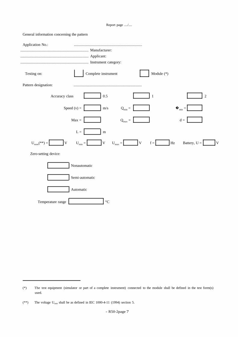
General information concerning the pattern
Application No.: .......................................................................
Manufacturer: .......................................................................
Applicant: .......................................................................
Instrument category: .......................................................................
Testing on: Complete instrument Module (*)
Pattern designation: .......................................................................
Accuracy class 0.5 1 2
Speed (v) = m/s Qmin = �min =
Max = Qmax = d =
L = m
Unom(**) = V Umin = V Umax = V f = Hz Battery, U = V
Zero-setting device:
Nonautomatic
Semi-automatic
Automatic
Temperature range °C
(*) The test equipment (simulator or part of a complete instrument) connected to the module shall be defined in the test form(s)
used.
(**) The voltage Unom shall be as defined in IEC 1000-4-11 (1994) section 5.
- R 50-2 page 8 -
Report page ..../....
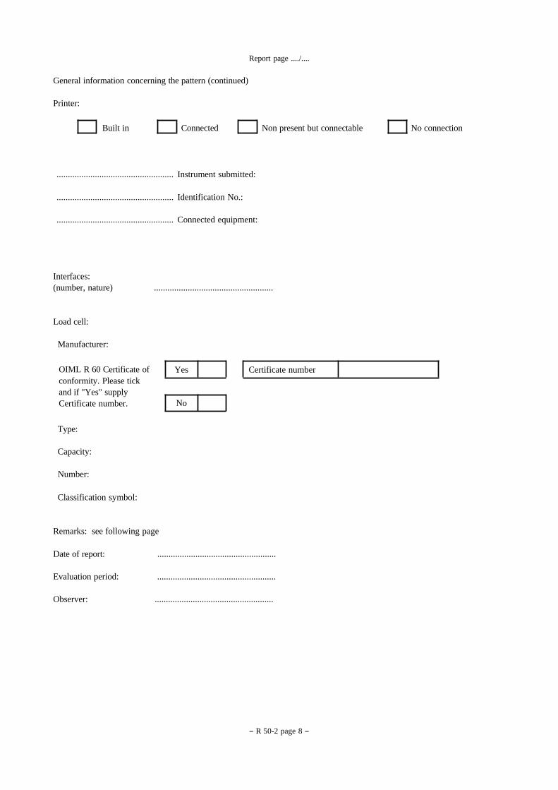
General information concerning the pattern (continued)
Printer:
Built in Connected Non present but connectable No connection
Instrument submitted: ....................................................
Identification No.:
....................................................
Connected equipment:
....................................................
Interfaces:
(number, nature) .....................................................
Load cell:
Manufacturer:
OIML R 60 Certificate of
conformity. Please tick
and if "Yes" supply
Certificate number.
Yes Certificate number
No
Type:
Capacity:
Number:
Classification symbol:
Remarks: see following page
Date of report: .....................................................
Evaluation period: .....................................................
Observer: .....................................................

- R50-2page 9
Report page ..../..
General information concerning the pattern (continued)
Use this space to indicate additional remarks and/or information: connecting equipment, interfaces and load cells, choice
of the manufacturer regarding protection against disturbances, etc.

- R 50-2 page 10
-
Report page ..../....
Passed
Failed
X
X
/
/
CHECKLIST
For each test, the "Summary of the checklist" and the "Checklist" shall be completed according to this example:
when the instrument has passed the test:
when the instrument has failed the test:
when the test is not applicable:
Summary of the checklist:
Requirement Passed Failed Remarks
Metrological requirements
R 50-1 clause 2
Technical requirements
R 50-1 clause 3
Requirements for electronic belt
weighers
R 50-1 clause 4
Metrological controls
R 50-1 clause 5
Test report
Overall result

- R50-2page 11
Report page ..../...
Summary of the checklist (remarks)
Use this page to detail remarks from the slllllmrny of the checklist
- R 50-2 page 12
-
Report page ..../....
Checklist
Application No.: ...............................................................................................................................
Pattern Designation: ...............................................................................................................................
Requirement
R 50-1 Test
procedure Belt weighers
Checklist
Passed
Failed
Remarks
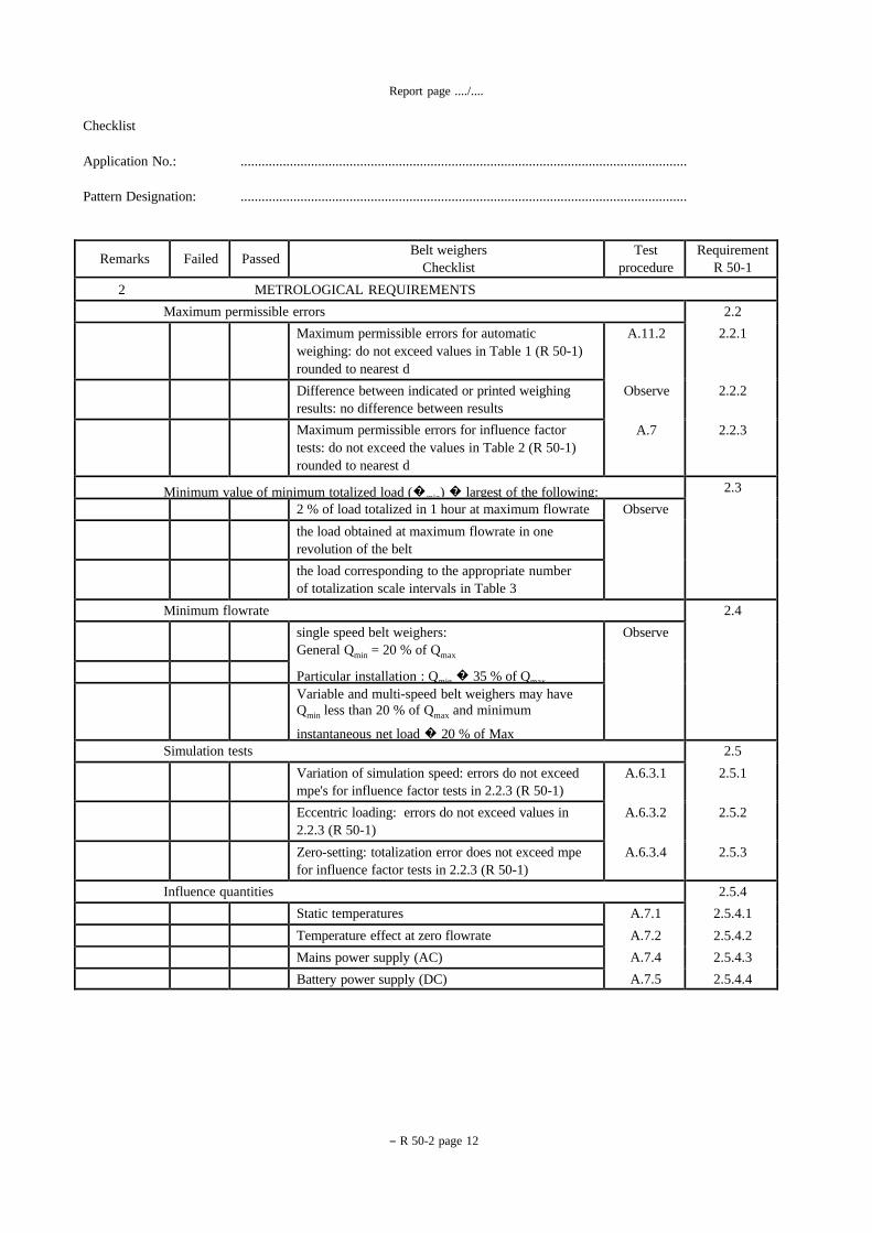
2 METROLOGICAL REQUIREMENTS
2.2
2.2.1
2.2.2
2.2.3
Maximum permissible errors
A.11.2
Observe
A.7
Maximum permissible errors for automatic
weighing: do not exceed values in Table 1 (R 50-1)
rounded to nearest d
Difference between indicated or printed weighing
results: no difference between results
Maximum permissible errors for influence factor
tests: do not exceed the values in Table 2 (R 50-1)
rounded to nearest d
2.3 Minimum value of minimum totalized load (�min) � largest of the following: Observe 2 % of load totalized in 1 hour at maximum flowrate
the load obtained at maximum flowrate in one
revolution of the belt
the load corresponding to the appropriate number
of totalization scale intervals in Table 3
2.4 Minimum flowrate
Observe single speed belt weighers:
General Qmin = 20 % of Qmax
Particular installation : Qmin � 35 % of Qmax
Variable and multi-speed belt weighers may have
Qmin less than 20 % of Qmax and minimum
instantaneous net load � 20 % of Max
2.5
2.5.1
2.5.2
2.5.3
Simulation tests
A.6.3.1
A.6.3.2
A.6.3.4
Variation of simulation speed: errors do not exceed
mpe's for influence factor tests in 2.2.3 (R 50-1)
Eccentric loading: errors do not exceed values in
2.2.3 (R 50-1)
Zero-setting: totalization error does not exceed mpe
for influence factor tests in 2.2.3 (R 50-1)
2.5.4
2.5.4.1
2.5.4.2
2.5.4.3
2.5.4.4
Influence quantities
A.7.1
A.7.2
A.7.4
A.7.5
Static temperatures
Temperature effect at zero flowrate
Mains power supply (AC)
Battery power supply (DC)
- R50-2page 13
Report page ..../....
Requirement
R 50-1 Test
procedure Belt weighers
Checklist
Passed
Failed
Remarks
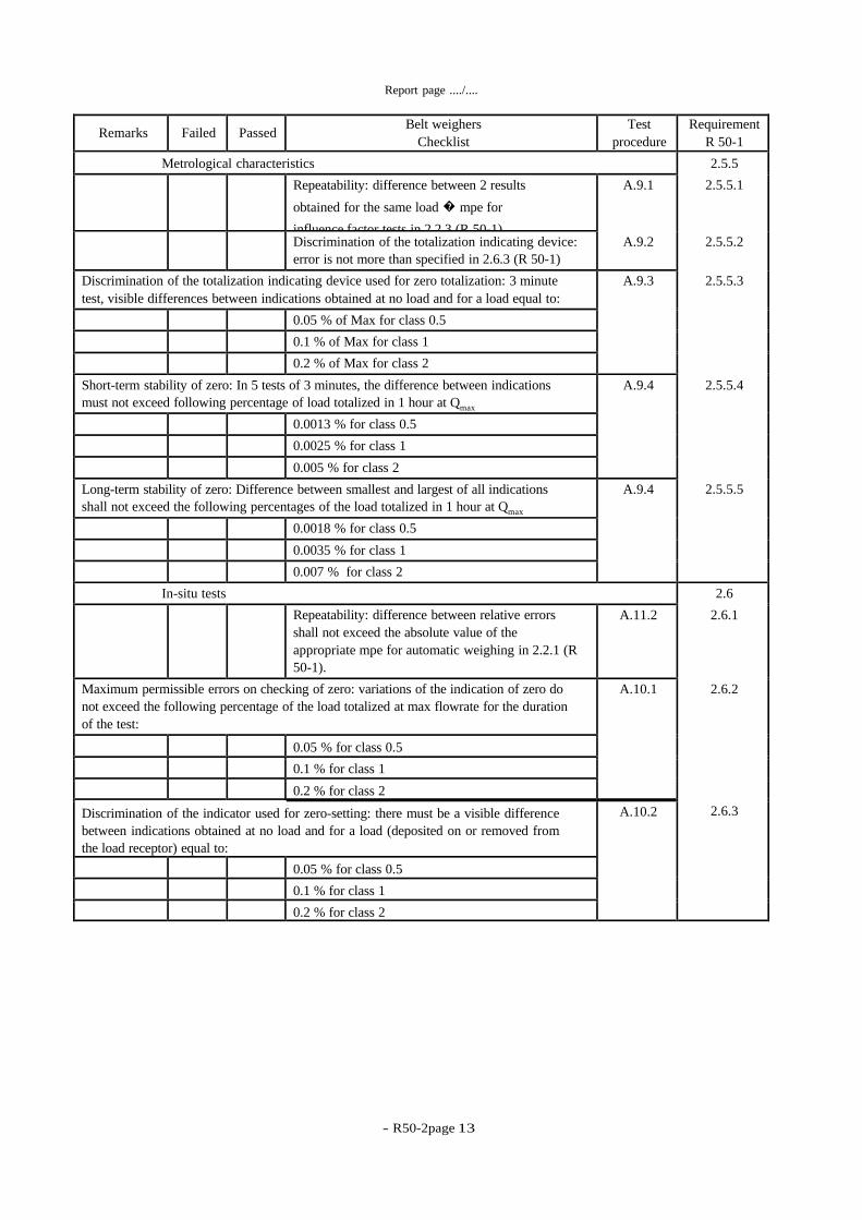
2.5.5
2.5.5.1
2.5.5.2
2.5.5.3
2.5.5.4
2.5.5.5
Metrological characteristics
A.9.1
A.9.2
Repeatability: difference between 2 results
obtained for the same load � mpe for
influence factor tests in 2.2.3 (R 50-1)
Discrimination of the totalization indicating device:
error is not more than specified in 2.6.3 (R 50-1)
A.9.3 Discrimination of the totalization indicating device used for zero totalization: 3 minute
test, visible differences between indications obtained at no load and for a load equal to:
0.05 % of Max for class 0.5
0.1 % of Max for class 1
0.2 % of Max for class 2
A.9.4 Short-term stability of zero: In 5 tests of 3 minutes, the difference between indications
must not exceed following percentage of load totalized in 1 hour at Qmax
0.0013 % for class 0.5
0.0025 % for class 1
0.005 % for class 2
A.9.4 Long-term stability of zero: Difference between smallest and largest of all indications
shall not exceed the following percentages of the load totalized in 1 hour at Qmax
0.0018 % for class 0.5
0.0035 % for class 1
0.007 % for class 2
2.6
2.6.1
2.6.2
2.6.3
In-situ tests
A.11.2 Repeatability: difference between relative errors
shall not exceed the absolute value of the
appropriate mpe for automatic weighing in 2.2.1 (R
50-1).
A.10.1 Maximum permissible errors on checking of zero: variations of the indication of zero do
not exceed the following percentage of the load totalized at max flowrate for the duration
of the test:
0.05 % for class 0.5
0.1 % for class 1
0.2 % for class 2 A.10.2 Discrimination of the indicator used for zero-setting: there must be a visible difference
between indications obtained at no load and for a load (deposited on or removed from
the load receptor) equal to:
0.05 % for class 0.5
0.1 % for class 1
0.2 % for class 2
- R 50-2 page 14
-
Report page ..../....
Requirement
R 50-1 Test
procedure Belt weighers
Checklist
Passed
Failed
Remarks
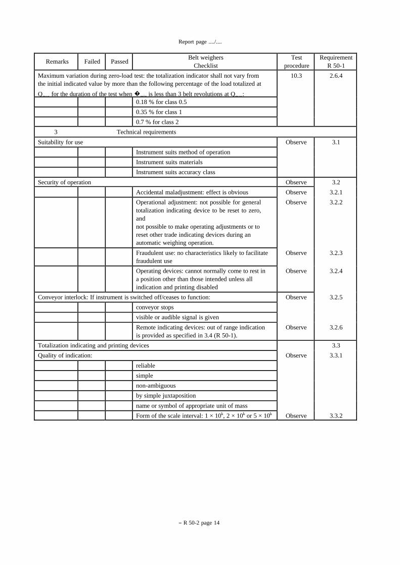
2.6.4 10.3 Maximum variation during zero-load test: the totalization indicator shall not vary from
the initial indicated value by more than the following percentage of the load totalized at
Qmax for the duration of the test when �min is less than 3 belt revolutions at Qmax: 0.18 % for class 0.5
0.35 % for class 1
0.7 % for class 2
3 Technical requirements
3.1 Observe Suitability for use
Instrument suits method of operation
Instrument suits materials
Instrument suits accuracy class
3.2
3.2.1
3.2.2
3.2.3
3.2.4
3.2.5
3.2.6
Observe Security of operation
Observe
Observe
Observe
Observe
Accidental maladjustment: effect is obvious
Operational adjustment: not possible for general
totalization indicating device to be reset to zero,
and
not possible to make operating adjustments or to
reset other trade indicating devices during an
automatic weighing operation.
Fraudulent use: no characteristics likely to facilitate
fraudulent use
Operating devices: cannot normally come to rest in
a position other than those intended unless all
indication and printing disabled
Observe
Observe
Conveyor interlock: If instrument is switched off/ceases to function:
conveyor stops
visible or audible signal is given
Remote indicating devices: out of range indication
is provided as specified in 3.4 (R 50-1).
3.3
3.3.1
3.3.2
Observe
Observe
Totalization indicating and printing devices
Quality of indication:
reliable
simple
non-ambiguous
by simple juxtaposition
name or symbol of appropriate unit of mass
Form of the scale interval: 1 × 10k, 2 × 10k or 5 × 10k

- R50-2page 15
Report page ..../....
Requirement
R 50-1 Test
procedure Belt weighers
Checklist
Passed
Failed
Remarks
3.3.3
3.3.4
3.3.5
3.3.6
Observe
Observe
Observe
Observe
Scale interval (d) of a partial totalization indicating
device: is equal to scale interval of the general
totalization indicating device
Scale interval of supplementary totalization
indicating devices: is at least equal to 10 times
totalization scale interval
Range of indication: at least one totalization
indicating device indicates a value equal to
quantity of product weighed in 10 hours of
operation at Qmax
Engagement of totalization indicating and printing
devices: permanently engaged
3.4 Observe Out-of-range indication: a continuous audible or visual indication shall be given when:
the instantaneous load is above the maximum
capacity of the weighing unit, or
the flowrate is above the maximum or below the
minimum value
3.5
3.5.1
Observe Zero-setting device: does not exceed 4 % of
maximum capacity
Semi-automatic and automatic zero-setting devices:
the setting to zero takes place after a whole number
of revolutions of the belt, and
the end of the zero-setting operation is indicated,
and
the limits of adjustment are indicated
shall be possible to disengage automatic zero-
setting devices during testing as appropriate
if an automatic zero-setting device is included must
have interlock to prevent zero-setting
3.6 Observe Displacement transducer
no possibility of slip whether the belt is loaded or
not
displacement sensing devices are driven by the
clean side of the belt
measurement signal to correspond with
displacement of belt equal to or less than weigh
length
adjustable parts can be sealed
3.7 Observe Belt weighers inclusive of conveyor
constructed in a rigid manner
shall form a rigid assembly
3.8 Observe Installation conditions (where applicable)
Instrument is installed where:
the frame support of the conveyor is constructed in
a rigid manner

- R 50-2 page 16
-
Report page ..../....
Requirement
R 50-1 Test
procedure Belt weighers
Checklist
Passed
Failed
Remarks
3.8.1
3.8.2
3.8.3
3.8.4
in any straight longitudinal section the roller track
is such that the belt is constantly supported on the
weighing rollers
belt cleaning devices, if fitted, are positioned and
operated so as to have no significant effect on the
results
roller track does not allow slippage to occur
Installation does not cause excessive additional
errors
Observe Roller track
is protected against corrosion and clogging
is aligned properly
Observe Conveyor belt
mass per unit length is practically constant
belt joints have no significant effect on the results
Observe Speed control
Single speed instruments:
speed of belt during weighing does not vary by
more than 5 % of nominal speed
Variable speed belt weighers (with speed setting control):
speed of the belt does not vary by more than 5 %
of the set speed
Observe Weigh length
remains unchanged in service
if adjustable, the adjusting devices can be sealed
3.8.5
3.8.6
3.9
Observe
Observe
Observe
Belt tension for belt weighers with weigh table: longitudinal tension is maintained
independent of the effects of:
temperature
wear
load
no slip between belt and driving drum
When conveyor length exceeds 10 m the roller that
transfers the force from the tensioner shall have an
arc at belt contact of not less than 90°
Overload protection: for accidental loads greater
than the maximum capacity
Ancillary devices: do not affect weighing results
- R50-2page 17
Report page ..../....
Requirement
R 50-1 Test
procedure Belt weighers
Checklist
Passed
Failed
Remarks
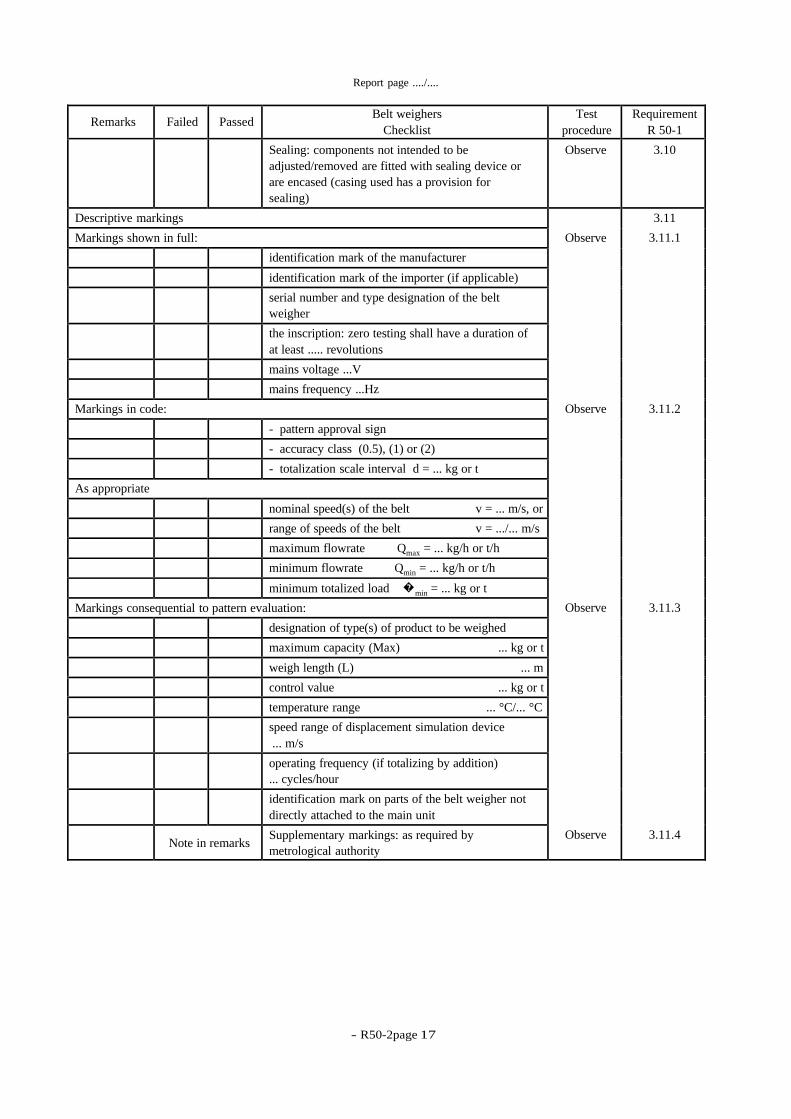
3.10 Observe Sealing: components not intended to be
adjusted/removed are fitted with sealing device or
are encased (casing used has a provision for
sealing)
3.11
3.11.1
3.11.2
3.11.3
3.11.4
Observe
Observe
Observe
Observe
Descriptive markings
Markings shown in full:
identification mark of the manufacturer
identification mark of the importer (if applicable)
serial number and type designation of the belt
weigher
the inscription: zero testing shall have a duration of
at least ..... revolutions
mains voltage ...V
mains frequency ...Hz
Markings in code:
- pattern approval sign
- accuracy class (0.5), (1) or (2)
- totalization scale interval d = ... kg or t
As appropriate
nominal speed(s) of the belt v = ... m/s, or
range of speeds of the belt v = .../... m/s
maximum flowrate Qmax = ... kg/h or t/h
minimum flowrate Qmin = ... kg/h or t/h
minimum totalized load �min = ... kg or t
Markings consequential to pattern evaluation:
designation of type(s) of product to be weighed
maximum capacity (Max) ... kg or t
weigh length (L) ... m
control value ... kg or t
temperature range ... °C/... °C
speed range of displacement simulation device
... m/s
operating frequency (if totalizing by addition)
... cycles/hour
identification mark on parts of the belt weigher not
directly attached to the main unit
Supplementary markings: as required by
metrological authority
Note in remarks

- R 50-2 page 18
-
Report page ..../....
Requirement
R 50-1 Test
procedure Belt weighers
Checklist
Passed
Failed
Remarks
3.11.5 Observe Presentation of descriptive markings
indelible Confirm
easily readable Confirm
grouped together in a clearly visible place either on
a descriptive plate near the general totalization
indicating device or on the indicating device itself.
Plate shall be sealable, unless it cannot be removed
without it being destroyed
Confirm
3.12
3.12.1
3.12.2
Observe Verification marks
Position of verification marks:
part on which it is located cannot be removed from
the belt weigher without damaging the marks
allows easy application of mark without changing
the metrological qualities of the belt weigher
is visible without the belt weigher or its protective
covers having to be moved when it is in service
Observe Mounting: Belt weighers required to have
verification marks shall have:
verification mark support, at the place provided for
above to ensure conservation of the marks
When the mark is made by a stamp, the support is a
strip of lead or other material with similar qualities
inserted into a plate fixed to the belt weigher or,
into a cavity in the belt weigher
space provided for adhesive transfer (if applicable)
4 Requirements for electronic belt weighers
4.1
4.1.1
4.1.2
4.1.3
4.1.4
General requirements
A.8
A.8.1
A.8.2
A.8.3
A.8.4
Observe
Observe
Rated operating conditions: errors do not exceed
mpe
Disturbances
Voltage dips and short interruptions
Electrical fast transients/burst immunity
Electrostatic discharges
Electromagnetic susceptibility
Durability: requirements of 4.1.1 and 4.1.2 shall be
met durably
Evaluation for compliance: instrument has passed
examination and tests specified in Annex A
- R50-2page 19
Report page ..../....
Requirement
R 50-1 Test
procedure Belt weighers
Checklist
Passed
Failed
Remarks
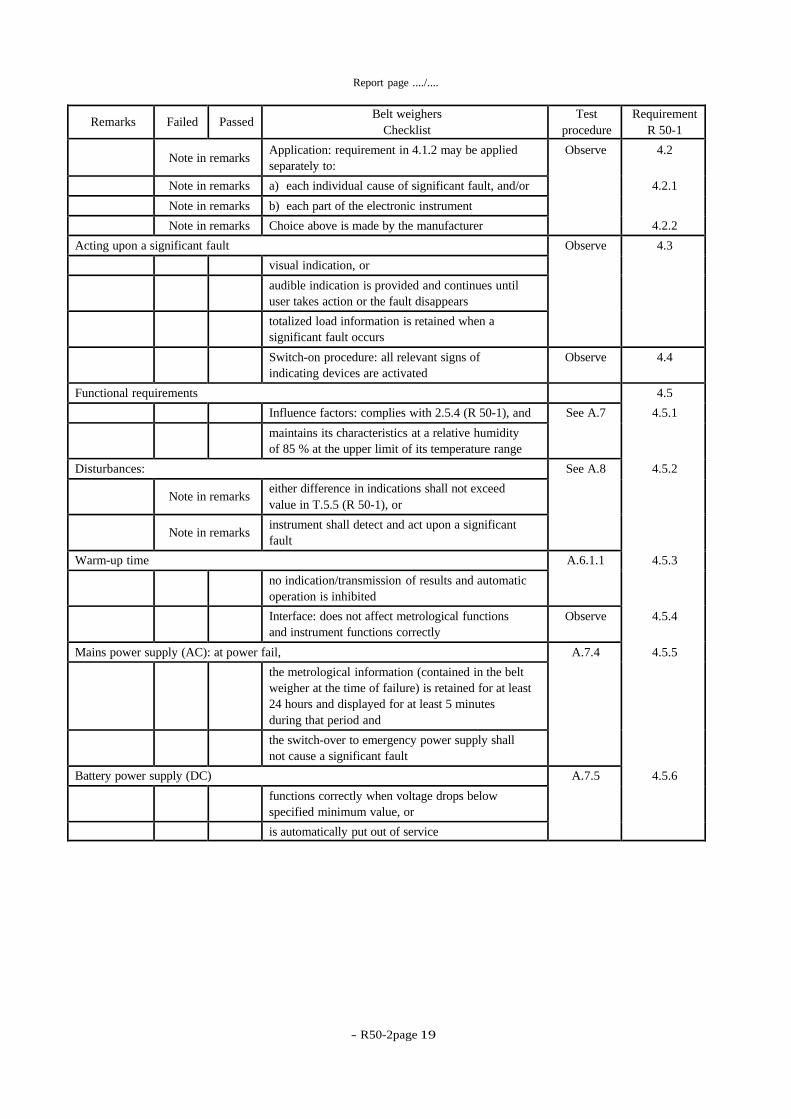
4.2
4.2.1
4.2.2
Observe Application: requirement in 4.1.2 may be applied
separately to:
Note in remarks
a) each individual cause of significant fault, and/or Note in remarks
b) each part of the electronic instrument Note in remarks
Choice above is made by the manufacturer Note in remarks
4.3 Observe Acting upon a significant fault
visual indication, or
audible indication is provided and continues until
user takes action or the fault disappears
totalized load information is retained when a
significant fault occurs
4.4 Observe Switch-on procedure: all relevant signs of
indicating devices are activated
4.5
4.5.1
4.5.2
4.5.3
4.5.4
4.5.5
4.5.6
Functional requirements
See A.7 Influence factors: complies with 2.5.4 (R 50-1), and
maintains its characteristics at a relative humidity
of 85 % at the upper limit of its temperature range
See A.8 Disturbances:
either difference in indications shall not exceed
value in T.5.5 (R 50-1), or
Note in remarks
instrument shall detect and act upon a significant
fault
Note in remarks
A.6.1.1 Warm-up time
no indication/transmission of results and automatic
operation is inhibited
Observe Interface: does not affect metrological functions
and instrument functions correctly
A.7.4 Mains power supply (AC): at power fail,
the metrological information (contained in the belt
weigher at the time of failure) is retained for at least
24 hours and displayed for at least 5 minutes
during that period and
the switch-over to emergency power supply shall
not cause a significant fault
A.7.5 Battery power supply (DC)
functions correctly when voltage drops below
specified minimum value, or
is automatically put out of service
- R 50-2 page 20
-
Report page ..../....
Requirement
R 50-1 Test
procedure Belt weighers
Checklist
Passed
Failed
Remarks
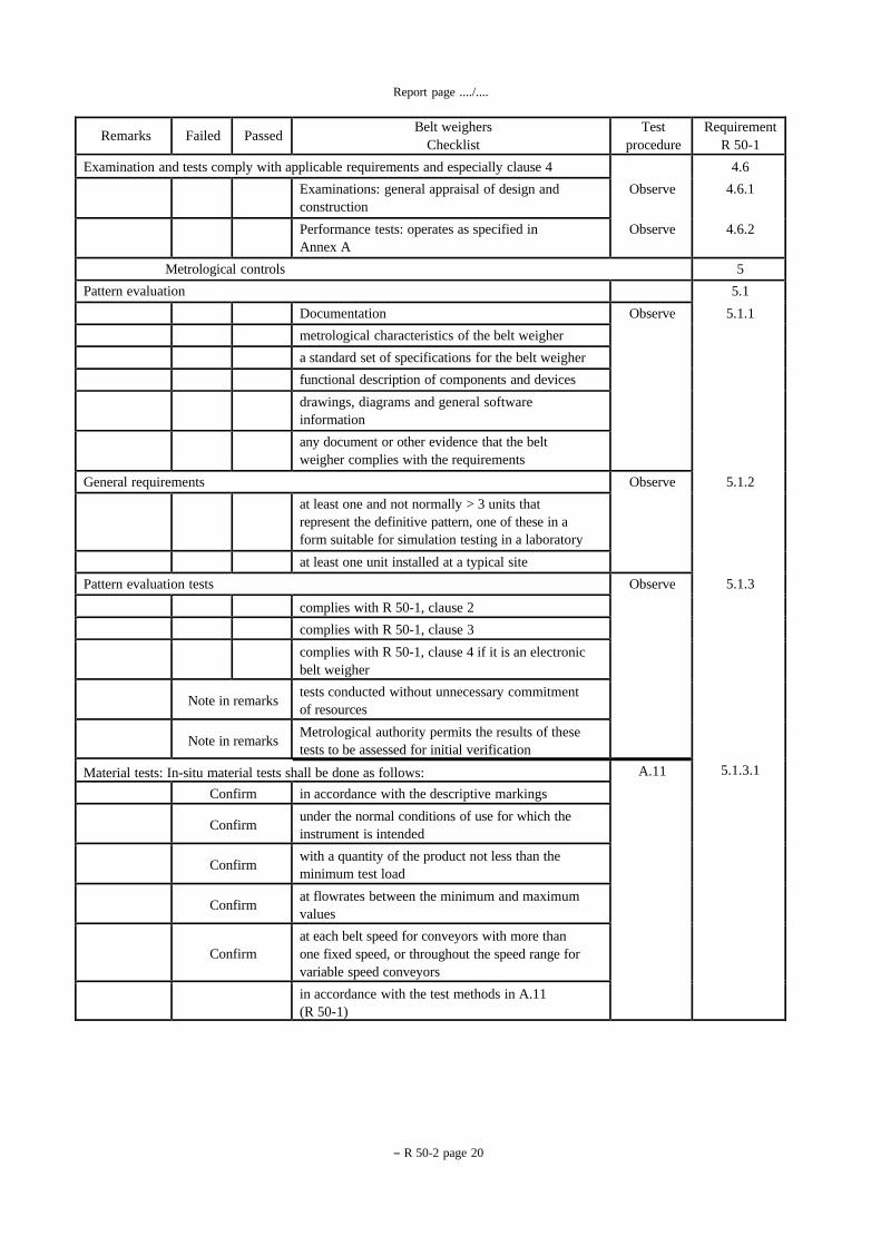
4.6
4.6.1
4.6.2
Observe
Observe
Examination and tests comply with applicable requirements and especially clause 4
Examinations: general appraisal of design and
construction
Performance tests: operates as specified in
Annex A
5 Metrological controls
5.1
5.1.1
5.1.2
5.1.3
5.1.3.1
Pattern evaluation
Observe Documentation
metrological characteristics of the belt weigher
a standard set of specifications for the belt weigher
functional description of components and devices
drawings, diagrams and general software
information
any document or other evidence that the belt
weigher complies with the requirements
Observe General requirements
at least one and not normally > 3 units that
represent the definitive pattern, one of these in a
form suitable for simulation testing in a laboratory
at least one unit installed at a typical site
Observe Pattern evaluation tests
complies with R 50-1, clause 2
complies with R 50-1, clause 3
complies with R 50-1, clause 4 if it is an electronic
belt weigher
tests conducted without unnecessary commitment
of resources
Note in remarks
Metrological authority permits the results of these
tests to be assessed for initial verification
Note in remarks
A.11 Material tests: In-situ material tests shall be done as follows:
in accordance with the descriptive markings Confirm
under the normal conditions of use for which the
instrument is intended
Confirm
with a quantity of the product not less than the
minimum test load
Confirm
at flowrates between the minimum and maximum
values
Confirm
at each belt speed for conveyors with more than
one fixed speed, or throughout the speed range for
variable speed conveyors
Confirm
in accordance with the test methods in A.11
(R 50-1)
- R50-2page 21
Report page ..../....
Requirement
R 50-1 Test
procedure Belt weighers
Checklist
Passed
Failed
Remarks
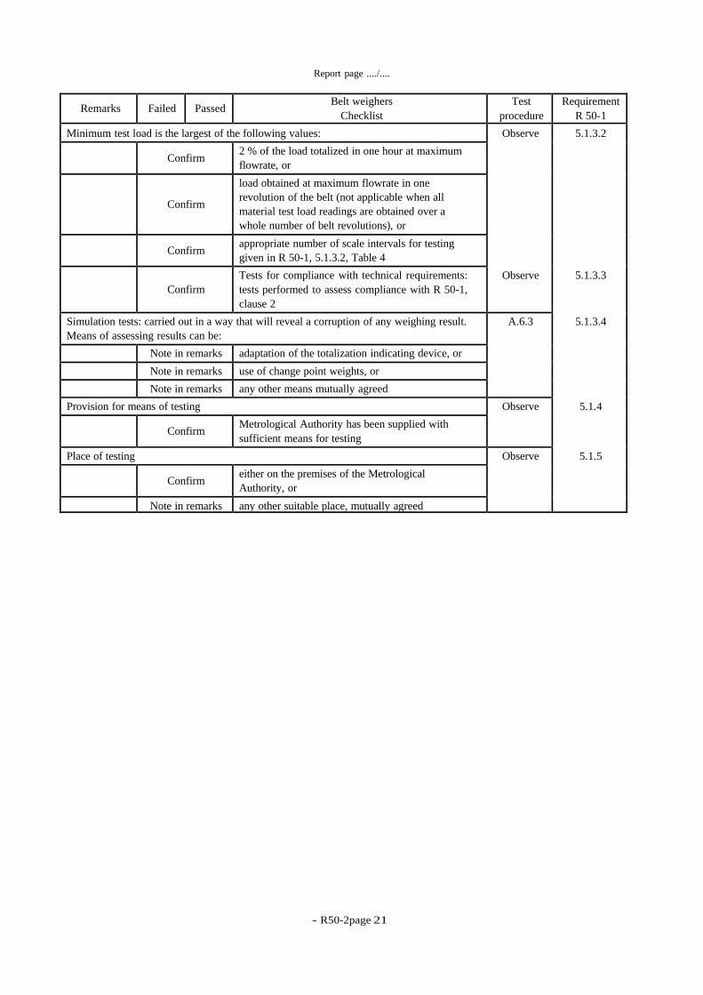
5.1.3.2
5.1.3.3
5.1.3.4
5.1.4
5.1.5
Observe
Observe
Minimum test load is the largest of the following values:
2 % of the load totalized in one hour at maximum
flowrate, or
Confirm
load obtained at maximum flowrate in one
revolution of the belt (not applicable when all
material test load readings are obtained over a
whole number of belt revolutions), or
Confirm
appropriate number of scale intervals for testing
given in R 50-1, 5.1.3.2, Table 4
Confirm
Tests for compliance with technical requirements:
tests performed to assess compliance with R 50-1,
clause 2
Confirm
A.6.3 Simulation tests: carried out in a way that will reveal a corruption of any weighing result.
Means of assessing results can be:
adaptation of the totalization indicating device, or Note in remarks
use of change point weights, or Note in remarks
any other means mutually agreed Note in remarks
Observe Provision for means of testing
Metrological Authority has been supplied with
sufficient means for testing
Confirm
Observe Place of testing
either on the premises of the Metrological
Authority, or
Confirm
any other suitable place, mutually agreed Note in remarks

- R 50-2 page 22
-
Report page ..../..
Use this page to detail remarks from the checklist

- R50-2page 23
Report page ..../....
TEST REPORT
Test equipment used for pattern evaluation
Application No.: ..........................................................................................................................
Report date:
..........................................................................................................................
Pattern designation:
..........................................................................................................................
Manufacturer:
..........................................................................................................................
List all test equipment used in this report:
Equipment name Manufacturer Type No. Serial No. Used for
(Test references)

- R 50-2 page 24
-
Report page ..../....
Configuration for test
Application No.: ..........................................................................................................................
Report date:
..........................................................................................................................
Pattern designation:
..........................................................................................................................
Manufacturer:
..........................................................................................................................
Use this space for additional information relating to equipment configuration, interfaces, data rates, load cells EMC
protection options etc., for the instrument and/or simulator.
- R50-2page 25
Report page ..../....
20.5 21.1
95:12:29 95:12:30
16:00:05 16:30:05
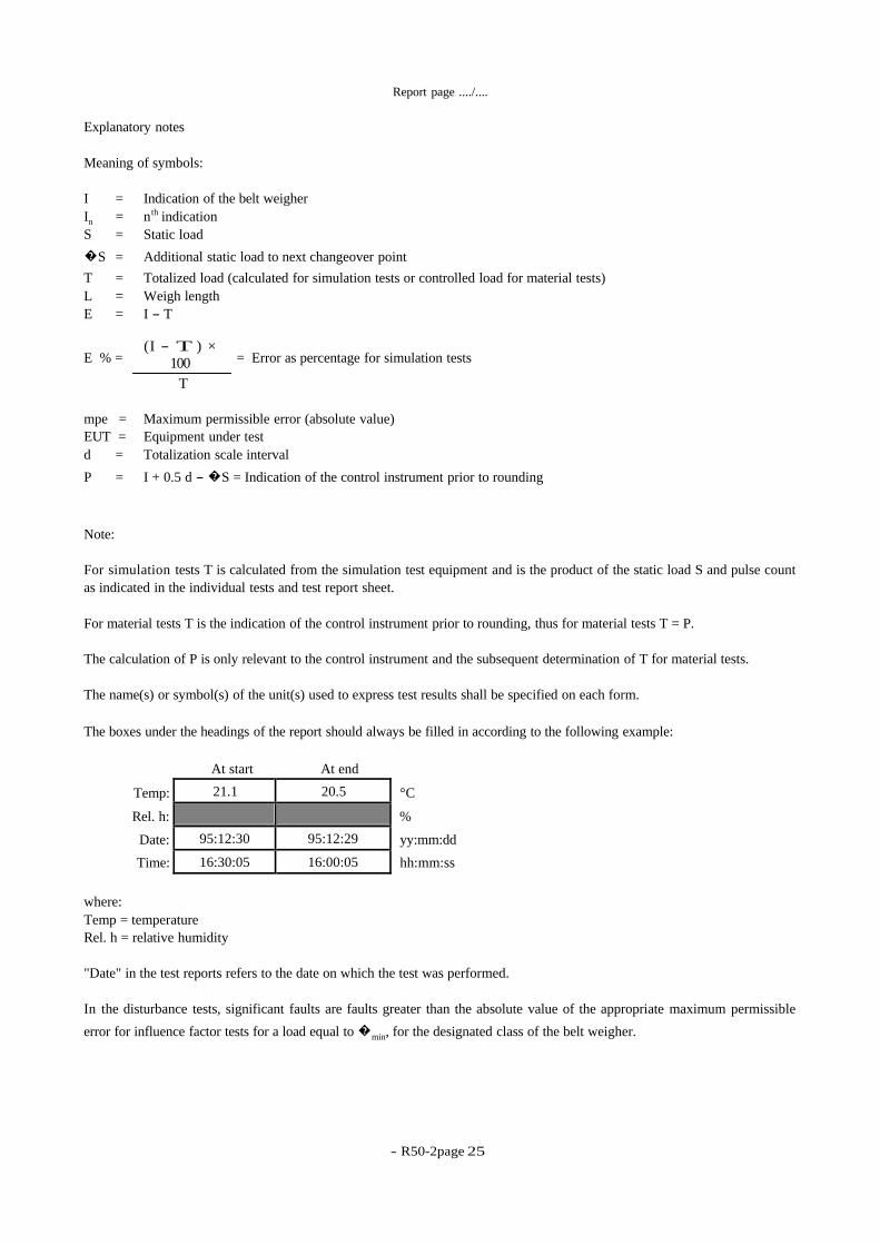
Explanatory notes
Meaning of symbols:
I = Indication of the belt weigher
th
In = n indication S = Static load
�S = Additional static load to next changeover point
T = Totalized load (calculated for simulation tests or controlled load for material tests)
L = Weigh length
E = I - T
E % = ( I - T ) ×
100
T
= Error as percentage for simulation tests
mpe = Maximum permissible error (absolute value)
EUT = Equipment under test
d = Totalization scale interval
P = I + 0.5 d - �S = Indication of the control instrument prior to rounding
Note:
For simulation tests T is calculated from the simulation test equipment and is the product of the static load S and pulse count
as indicated in the individual tests and test report sheet.
For material tests T is the indication of the control instrument prior to rounding, thus for material tests T = P.
The calculation of P is only relevant to the control instrument and the subsequent determination of T for material tests.
The name(s) or symbol(s) of the unit(s) used to express test results shall be specified on each form.
The boxes under the headings of the report should always be filled in according to the following example:
Temp:
At start At end
°C
Rel. h: %
Date:
Time:
yy:mm:dd
hh:mm:ss
where:
Temp = temperature
Rel. h = relative humidity
"Date" in the test reports refers to the date on which the test was performed.
In the disturbance tests, significant faults are faults greater than the absolute value of the appropriate maximum permissible
error for influence factor tests for a load equal to �min, for the designated class of the belt weigher.
- R 50-2 page 26
-
Report page ..../....
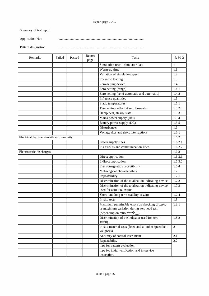
Summary of test report
Application No.: ......................................................................................................
Pattern designation: ......................................................................................................
R 50-2 Tests Report
page Passed Failed Remarks
1 Simulation tests - simulator data 1.1 Warm-up time 1.2 Variation of simulation speed 1.3 Eccentric loading 1.4 Zero-setting device 1.4.1 Zero-setting (range) 1.4.2 Zero-setting (semi-automatic and automatic) 1.5 Influence quantities 1.5.1 Static temperatures 1.5.2 Temperature effect at zero flowrate 1.5.3 Damp heat, steady state 1.5.4 Mains power supply (AC) 1.5.5 Battery power supply (DC) 1.6 Disturbances 1.6.1 Voltage dips and short interruptions 1.6.2 Electrical fast transients/burst immunity
1.6.2.1 Power supply lines 1.6.2.2 I/O circuits and communication lines 1.6.3 Electrostatic discharges
1.6.3.1 Direct application 1.6.3.2 Indirect application 1.6.4 Electromagnetic susceptibility 1.7 Metrological characteristics 1.7.1 Repeatability 1.7.2 Discrimination of the totalization indicating device 1.7.3 Discrimination of the totalization indicating device
used for zero totalization
1.7.4 Short- and long-term stability of zero 1.8 In-situ tests 1.8.1 Maximum permissible errors on checking of zero,
or maximum variation during zero load test
(depending on ratio rev/�min)
1.8.2 Discrimination of the indicator used for zero-
setting
2 In-situ material tests (fixed and all other speed belt
weighers)
2.1 Accuracy of control instrument 2.2 Repeatability
mpe for pattern evaluation mpe for initial verification and in-service
inspection.

- R50-2page 27
Report page ..../....
1 Simulation tests (R 50-1, 5.1.3.4 & A.6.3)
Simulator data
Application No.: ...............................................................................................
Pattern designation:
...............................................................................................
Date:
...............................................................................................
Observer:
...............................................................................................
Data Derivation Ref Value Units
Maximum flowrate Max at maximum speed Qmax
Totalization scale interval d
Zero-setting scale interval
Simulator resolution(*) d
Max weigh table capacity To obtain Qmax Max
Weigh length L m
Pulses per weigh length
Nominal speed or
Range of speeds
v = .. m/s
v = ../.. m/s
(**)
(*) Where:
Simulator resolution "d" is obtained by using one of the methods in the "Note" in R 50-1, 5.1.3.4. If other means are
agreed (including the error calculation method in R 50-1, A.4.2), they should be noted below.
(**) Insert other relevant data as necessary.
Detail formula for calculating totalized load for simulation tests:
example:
T Pulses transmitted × S
Pulses per weigh length
T =
DESCRIPTION OF SIMULATOR:
(Must include details of any differences from installed instruments)
- R 50-2 page 28
-
Report page ..../....
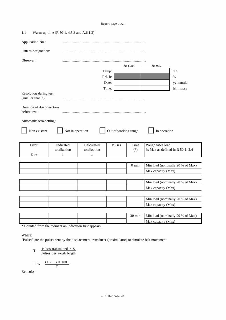
1.1 Warm-up time (R 50-1, 4.5.3 and A.6.1.2)
Application No.: ............................................................................................
Pattern designation: ............................................................................................
Observer: ............................................................................................
At start At end
Temp: °C
Rel. h: %
Date: yy:mm:dd
Time: hh:mm:ss
Resolution during test:
(smaller than d) ............................................................................................
Duration of disconnection
before test: ............................................................................................
Automatic zero-setting:
Non existent Not in operation Out of working range In operation
Weigh table load
% Max as defined in R 50-1, 2.4 Time
(*) Pulses Calculated
totalization
T
Indicated
totalization
I
Error
E %
Min load (nominally 20 % of Max) 0 min
Max capacity (Max)
Min load (nominally 20 % of Max)
Max capacity (Max)
Min load (nominally 20 % of Max)
Max capacity (Max)
Min load (nominally 20 % of Max) 30 min
Max capacity (Max) * Counted from the moment an indication first appears.
Where:
"Pulses" are the pulses sent by the displacement transducer (or simulator) to simulate belt movement
T Pulses transmitted × S
Pulses p er weigh length
E % ( I - T ) × 100
T
Remarks:
- R50-2page 29
Report page ..../....
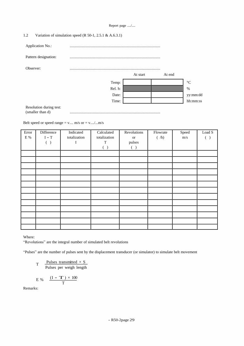
1.2 Variation of simulation speed (R 50-1, 2.5.1 & A.6.3.1)
Application No.: ............................................................................................
Pattern designation: ............................................................................................
Observer: ............................................................................................
At start At end
Resolution during test:
Temp: °C
Rel. h: %
Date: yy:mm:dd
Time: hh:mm:ss
(smaller than d) ............................................................................................
Belt speed or speed range = v.... m/s or = v..../...m/s
Load S
( ) Speed
m/s Flowrate
( /h) Revolutions
or
pulses
( )
Calculated
totalization
T
( )
Indicated
totalization
I
Difference
I - T
( )
Error
E %
Where:
“Revolutions” are the integral number of simulated belt revolutions
“Pulses” are the number of pulses sent by the displacement transducer (or simulator) to simulate belt movement
T Pulses transmitted × S
Pulses per weigh length
E % ( I - T ) × 100
T
Remarks:
- R 50-2 page 30
-
Report page ..../....
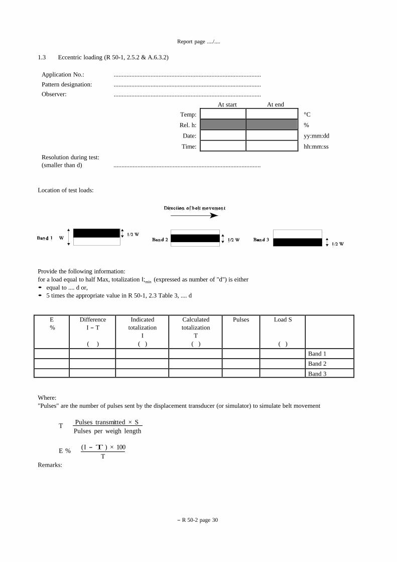
1.3 Eccentric loading (R 50-1, 2.5.2 & A.6.3.2)
Application No.:
Pattern designation:
Observer:
............................................................................................
............................................................................................
............................................................................................
At start At end
Resolution during test:
Temp: °C
Rel. h: %
Date: yy:mm:dd
Time: hh:mm:ss
(smaller than d) ............................................................................................
Location of test loads:
Provide the following information:
for a load equal to half Max, totalization I;min (expressed as number of "d") is either
• equal to .... d or,
• 5 times the appropriate value in R 50-1, 2.3 Table 3, .... d
Load S
( )
Pulses Calculated
totalization
T
( )
Indicated
totalization
I
( )
Difference
I - T
( )
E
%
Band 1
Band 2
Band 3
Where:
"Pulses" are the number of pulses sent by the displacement transducer (or simulator) to simulate belt movement
T Pulses transmitted × S
Pulses per weigh length
E % ( I - T ) × 100
T
Remarks:
- R50-2page 31
Report page ..../....
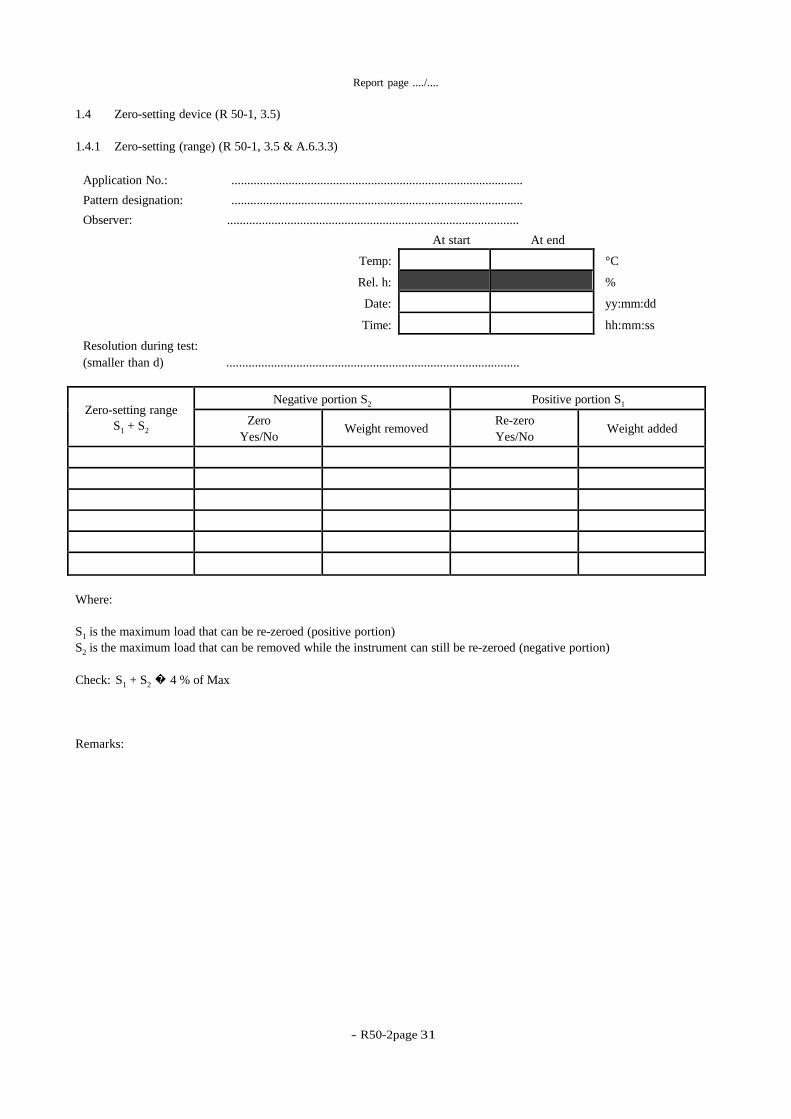
1.4 Zero-setting device (R 50-1, 3.5)
1.4.1 Zero-setting (range) (R 50-1, 3.5 & A.6.3.3)
Application No.: ............................................................................................
Pattern designation: ............................................................................................
Observer: ............................................................................................
At start At end
Temp: °C
Rel. h: %
Date: yy:mm:dd
Time: hh:mm:ss
Resolution during test:
(smaller than d) ............................................................................................
Positive portion S1 Negative portion S2 Zero-setting range
S1 + S2
Weight added Re-zero
Yes/No
Weight removed Zero
Yes/No
Where:
S1 is the maximum load that can be re-zeroed (positive portion)
S2 is the maximum load that can be removed while the instrument can still be re-zeroed (negative portion)
Check: S1 + S2 � 4 % of Max
Remarks:

- R 50-2 page 32
-
Report page ..../....
1.4.2 Zero-setting (semi-automatic and automatic) (R 50-1, 2.5.3 & A.6.3.4)
Application No.:
Pattern designation:
Observer:
............................................................................................
............................................................................................
............................................................................................
At start At end
Resolution during test:
Temp: °C
Rel. h: %
Date: yy:mm:dd
Time: hh:mm:ss
(smaller than d) ............................................................................................
Load S
( )
Pulses Calculated
totalization
T
( )
Indicated
totalization
I
( )
Difference
I - T
( )
E
%
S1
S2
S3
S4
Where:
S1 = 50 % of positive zero-setting range
S2 = 100 % of positive zero-setting range
S3 = -50 % of negative zero-setting range
S4 = -100 % of negative zero-setting range
"Pulses" are the number of pulses sent by the displacement transducer (or simulator) to simulate belt movement
T Pulses transmitted × S
Pulses per weigh length
E % ( I - T ) × 100
T
Remarks:

- R50-2page 33
Report page ..../....
1.5 Influence quantities (R 50-1, 2.5.4 & A.7)
1.5.1 Static temperatures (R 50-1, 2.5.4.1 & A.7.1)
Application No.: ............................................................................................
Pattern designation: ............................................................................................
Observer: ............................................................................................
Resolution during test:
(smaller than d)
............................................................................................
Confirm automatic zero-setting device is:
Non existent Not in operation Out of working range
Pre-test information
Flowrate
( /h)
Equivalent
pulses for
�min
Static load (S) for
�min
( ) Qmax
Qintermediate Q
min
Test results (Note at each “Q” the test is repeated)
Test 1 - Static temperature 20 °C
At start At end
Temp: °C
Rel. h: %
Date: yy:mm:dd
Time: hh:mm:ss
Q
( /h)
Load S
( )
Pulses Calculated
totalization
T
( )
Indicated
totalization
I
( )
Difference
I - T
( )
E
%
Qmin
Qintermediate
Qmax
Qmin
- R 50-2 page 34
-
Report page ..../....
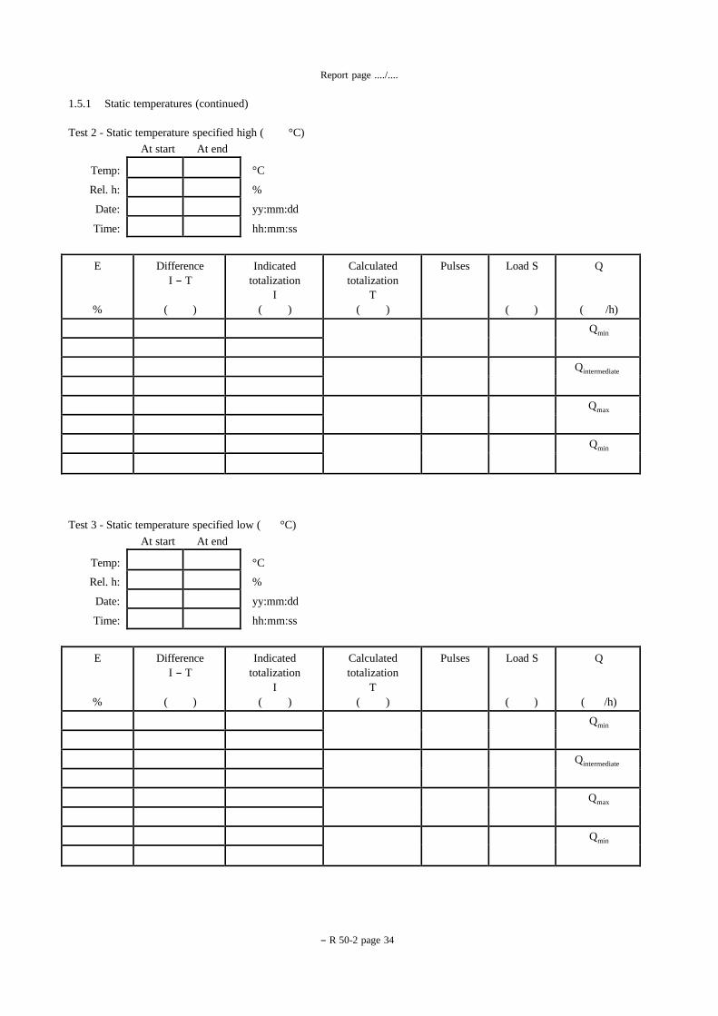
1.5.1 Static temperatures (continued)
Test 2 - Static temperature specified high ( °C)
At start At end
Temp: °C
Rel. h: %
Date: yy:mm:dd
Time: hh:mm:ss
Q
( /h)
Load S
( )
Pulses Calculated
totalization
T
( )
Indicated
totalization
I
( )
Difference
I - T
( )
E
%
Qmin
Qintermediate
Qmax
Qmin
Test 3 - Static temperature specified low ( °C)
At start At end
Temp: °C
Rel. h: %
Date: yy:mm:dd
Time: hh:mm:ss
Q
( /h)
Load S
( )
Pulses Calculated
totalization
T
( )
Indicated
totalization
I
( )
Difference
I - T
( )
E
%
Qmin
Qintermediate
Qmax
Qmin
- R50-2page 35
Report page ..../....
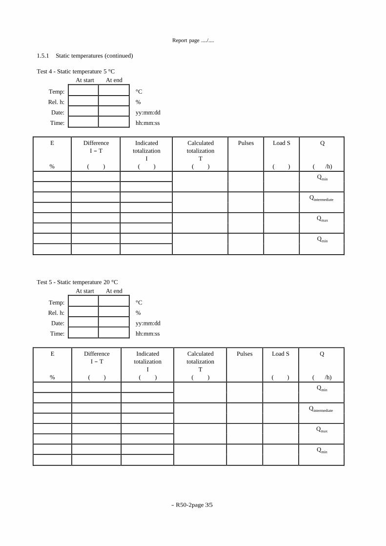
1.5.1 Static temperatures (continued)
Test 4 - Static temperature 5 °C
At start At end
Temp: °C
Rel. h: %
Date: yy:mm:dd
Time: hh:mm:ss
Q
( /h)
Load S
( )
Pulses Calculated
totalization
T
( )
Indicated
totalization
I
( )
Difference
I - T
( )
E
%
Qmin
Qintermediate
Qmax
Qmin
Test 5 - Static temperature 20 °C
At start At end
Temp: °C
Rel. h: %
Date: yy:mm:dd
Time: hh:mm:ss
Q
( /h)
Load S
( )
Pulses Calculated
totalization
T
( )
Indicated
totalization
I
( )
Difference
I - T
( )
E
%
Qmin
Qintermediate
Qmax
Qmin

- R 50-2 page 36
-
Report page ..../....
1.5.1 Static temperatures (continued)
Where:
"Pulses" are the number of pulses sent by the displacement transducer (or simulator) to simulate belt movement
T Pulses transmitted × S
Pulses p er weigh length
E % ( I - T ) × 100
T
Remarks:

- R50-2page 37
Report page ..../....
Report
page
(*)
Date Time
1.5.2 Temperature effect at zero flowrate (R 50-1, 2.5.4.2 & A.7.2)
Application No.: ............................................................................................
Pattern designation: ............................................................................................
Observer: ............................................................................................
Resolution during test:
(smaller than d)
............................................................................................
Confirm automatic zero-setting device is:
Non existent Not in operation Out of working range
Temperature at start specified minimum ( ) °C
At start At end
Rel. h: %
Date: yy:mm:dd
Time: hh:mm:ss
Temp
°C
Pulses Indicated
totalization
I at start
( )
Indicated
totalization
I at end
( )
Change in
indication
( )
Start temp
End temp
Start temp
End temp
Start temp
End temp
Start temp
End temp
Start temp
End temp
Where:
temp = temperature
The difference between each start temperature and end temperature is to be 10 °C with the rate of temperature change not
to exceed 5 °C per hour.
Remarks:
(*) Indicate the report page of the relevant test where the temperature effect at zero flowrate and static temperature tests are conducted
together.
- R 50-2 page 38
-
Report page ..../....
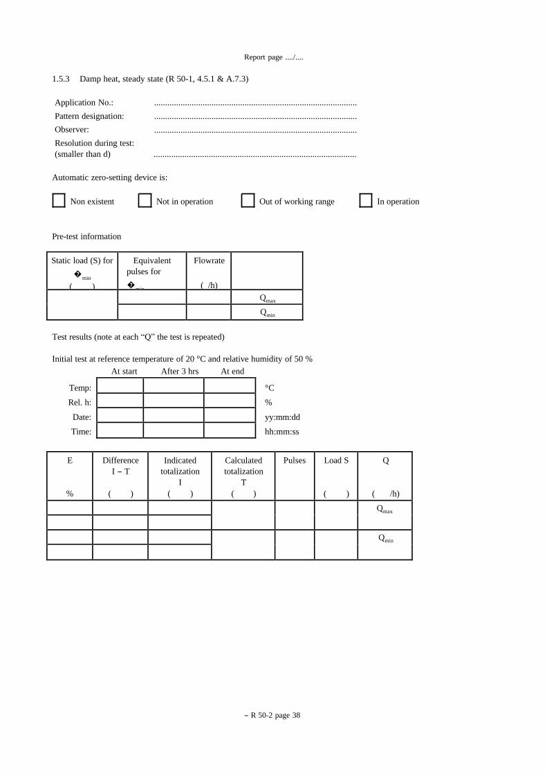
1.5.3 Damp heat, steady state (R 50-1, 4.5.1 & A.7.3)
Application No.:
Pattern designation:
Observer:
............................................................................................
............................................................................................
............................................................................................
Resolution during test:
(smaller than d) ............................................................................................
Automatic zero-setting device is:
Non existent Not in operation Out of working range In operation
Pre-test information
Flowrate
( /h)
Equivalent
pulses for
�min
Static load (S) for
�min
( ) Qmax
Qmin
Test results (note at each “Q” the test is repeated)
Initial test at reference temperature of 20 °C and relative humidity of 50 %
At start After 3 hrs At end
Temp: °C
Rel. h: %
Date: yy:mm:dd
Time: hh:mm:ss
Q
( /h)
Load S
( )
Pulses Calculated
totalization
T
( )
Indicated
totalization
I
( )
Difference
I - T
( )
E
%
Qmax
Qmin
- R50-2page 39
Report page ..../....
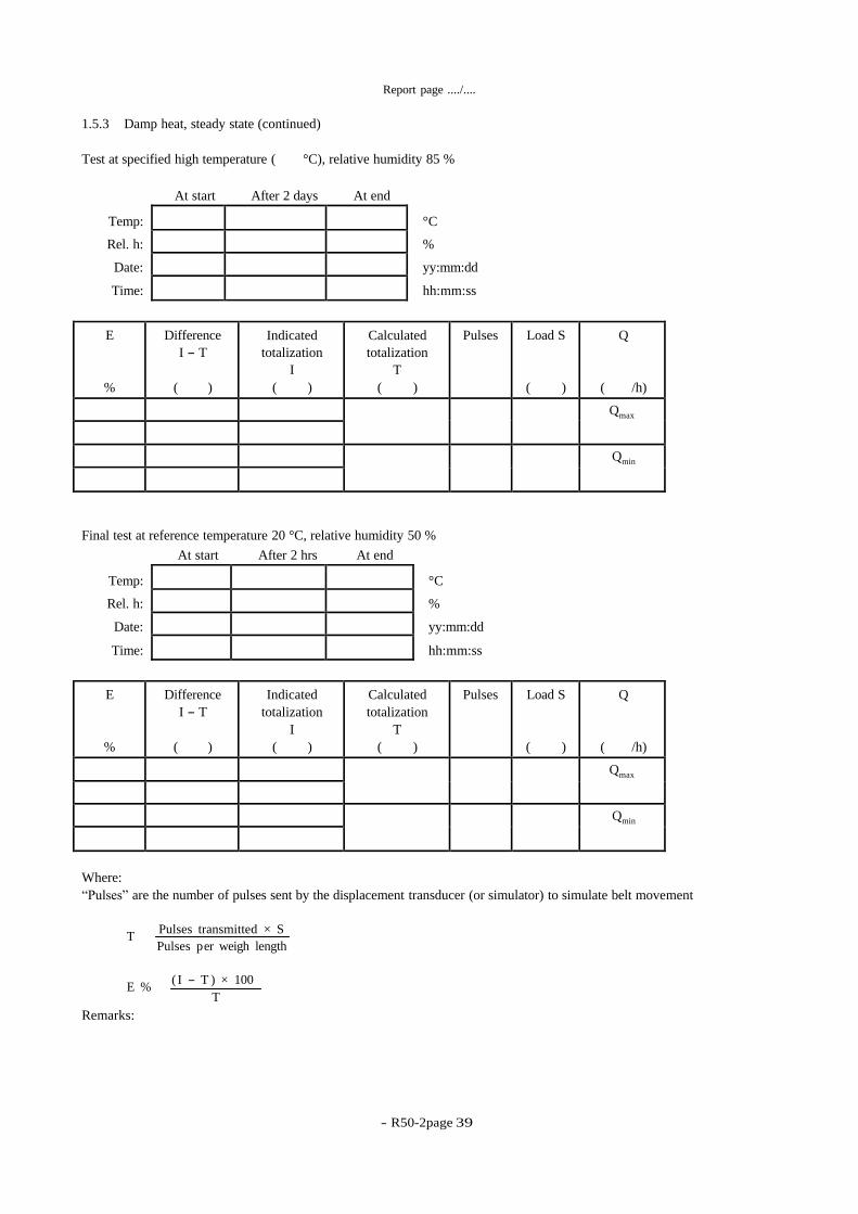
1.5.3 Damp heat, steady state (continued)
Test at specified high temperature ( °C), relative humidity 85 %
At start After 2 days At end
Temp: °C
Rel. h: %
Date: yy:mm:dd
Time: hh:mm:ss
Q
( /h)
Load S
( )
Pulses Calculated
totalization
T
( )
Indicated
totalization
I
( )
Difference
I - T
( )
E
%
Qmax
Qmin
Final test at reference temperature 20 °C, relative humidity 50 %
At start After 2 hrs At end
Temp: °C
Rel. h: %
Date: yy:mm:dd
Time: hh:mm:ss
Q
( /h)
Load S
( )
Pulses Calculated
totalization
T
( )
Indicated
totalization
I
( )
Difference
I - T
( )
E
%
Qmax
Qmin
Where:
“Pulses” are the number of pulses sent by the displacement transducer (or simulator) to simulate belt movement
T Pulses transmitted × S
Pulses p er weigh length
E % ( I - T ) × 100
T
Remarks:
- R 50-2 page 40
-
Report page ..../....
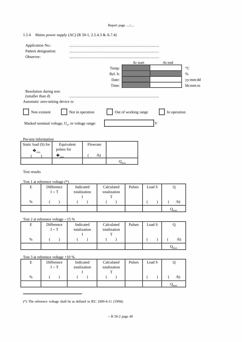
1.5.4 Mains power supply (AC) (R 50-1, 2.5.4.3 & A.7.4)
Application No.:
Pattern designation:
Observer:
............................................................................................
............................................................................................
............................................................................................
At start At end
Resolution during test:
Temp: °C
Rel. h: %
Date: yy:mm:dd
Time: hh:mm:ss
(smaller than d) ............................................................................................
Automatic zero-setting device is:
Non existent Not in operation Out of working range In operation
Marked nominal voltage, Un, or voltage range: V
Pre-test information
Flowrate
( /h)
Equivalent
pulses for
�min
Static load (S) for
�min
( ) Qmax
Test results
Test 1 at reference voltage (*)
Q
( /h)
Load S
( )
Pulses Calculated
totalization
T
( )
Indicated
totalization
I
( )
Difference
I - T
( )
E
%
Qmax
Test 2 at reference voltage -15 %
Q
( /h)
Load S
( )
Pulses Calculated
totalization
T
( )
Indicated
totalization
I
( )
Difference
I - T
( )
E
%
Qmax
Test 3 at reference voltage +10 %
Q
( /h)
Load S
( )
Pulses Calculated
totalization
T
( )
Indicated
totalization
I
( )
Difference
I - T
( )
E
%
Qmax
(*) The reference voltage shall be as defined in IEC 1000-4-11 (1994).
Report page ..../....
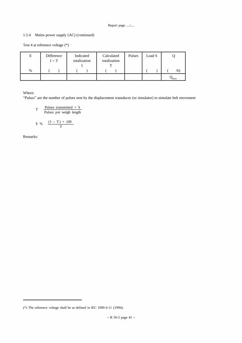
(*) The reference voltage shall be as defined in IEC 1000-4-11 (1994).
- R 50-2 page 41 -
1.5.4 Mains power supply (AC) (continued)
Test 4 at reference voltage (*)
Q
( /h)
Load S
( )
Pulses Calculated
totalization
T
( )
Indicated
totalization
I
( )
Difference
I - T
( )
E
%
Qmax
Where:
“Pulses” are the number of pulses sent by the displacement transducer (or simulator) to simulate belt movement
T Pulses transmitted × S
Pulses p er weigh length
E % ( I - T ) × 100
T
Remarks:
Report page ..../....
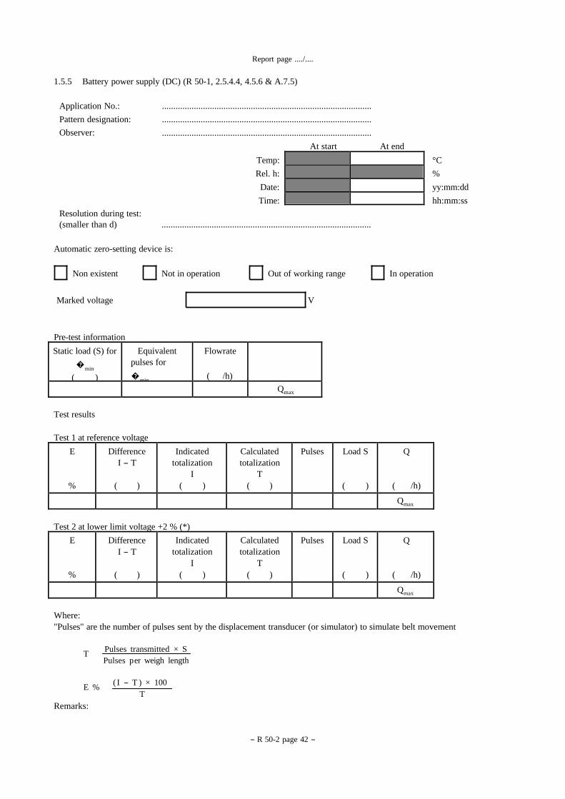
1.5.5 Battery power supply (DC) (R 50-1, 2.5.4.4, 4.5.6 & A.7.5)
Application No.:
Pattern designation:
Observer:
............................................................................................
............................................................................................
............................................................................................
At start At end
- R 50-2 page 42 -
Resolution during test:
Temp: °C
Rel. h: %
Date: yy:mm:dd
Time: hh:mm:ss
(smaller than d) ............................................................................................
Automatic zero-setting device is:
Non existent Not in operation Out of working range In operation
Marked voltage V
Pre-test information
Flowrate
( /h)
Equivalent
pulses for
�min
Static load (S) for
�min
( ) Qmax
Test results
Test 1 at reference voltage
Q
( /h)
Load S
( )
Pulses Calculated
totalization
T
( )
Indicated
totalization
I
( )
Difference
I - T
( )
E
%
Qmax
Test 2 at lower limit voltage +2 % (*)
Q
( /h)
Load S
( )
Pulses Calculated
totalization
T
( )
Indicated
totalization
I
( )
Difference
I - T
( )
E
%
Qmax
Where:
"Pulses" are the number of pulses sent by the displacement transducer (or simulator) to simulate belt movement
T Pulses transmitted × S
Pulses p er weigh length
E % ( I - T ) × 100
T
Remarks:
(*) The reference voltage shall be as defined in IEC 1000-4-11 (1994).
- R 50-2 page 43 -
Report page ..../....
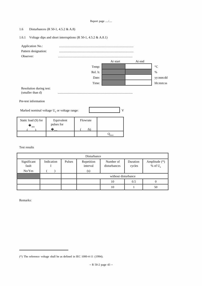
1.6 Disturbances (R 50-1, 4.5.2 & A.8)
1.6.1 Voltage dips and short interruptions (R 50-1, 4.5.2 & A.8.1)
Application No.: ............................................................................................
Pattern designation: ............................................................................................
Observer: ............................................................................................
At start At end
Temp: °C
Rel. h: %
Date: yy:mm:dd
Time: hh:mm:ss
Resolution during test:
(smaller than d) ............................................................................................
Pre-test information
Marked nominal voltage Un or voltage range: V
Flowrate
( /h)
Equivalent
pulses for
�min
Static load (S) for
�min
( ) Qmax
Test results
Disturbance
Amplitude (*)
% of Un Duration
cycles Number of
disturbances Repetition
interval
(s)
Pulses Indication
I
( )
Significant
fault
No/Yes
without disturbance
0 0.5 10
50 1 10
Remarks:

- R 50-2 page 44 -
Report page ..../....
1.6.2 Electrical fast transients/burst immunity (R 50-1, 4.5.2 & A.8.2)
1.6.2.1 Power supply lines
Application No.: ............................................................................................
Pattern designation: ............................................................................................
Observer: ............................................................................................
At start At end
Temp: °C
Rel. h: %
Date: yy:mm:dd
Time: hh:mm:ss
Resolution during test:
(smaller than d) ............................................................................................
Pre-test information
Flowrate
( /h)
Equivalent
pulses for
�min
Static load (S) for
�min
( ) Qmax
Test results
Power supply lines: test voltage 1 kV, duration of the test 1 min at each polarity
L = live, N = neutral, PE = protective earth
Connection Polarity L
ground
N
ground
PE
ground
Pulses Indicated
totalization
I
( )
Significant
fault
Yes/No
without disturbance
X
pos neg
without disturbance
X
pos neg
without disturbance
X
pos
neg
Remarks:
Report page ..../....
- R 50-2 page 45 -
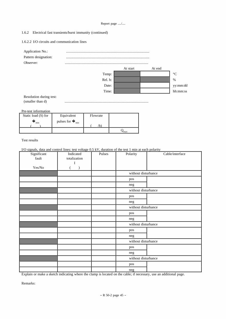
1.6.2 Electrical fast transients/burst immunity (continued)
1.6.2.2 I/O circuits and communication lines
Application No.: ............................................................................................
Pattern designation: ............................................................................................
Observer: ............................................................................................
At start At end
Temp: °C
Rel. h: %
Date: yy:mm:dd
Time: hh:mm:ss
Resolution during test:
(smaller than d) ............................................................................................
Pre-test information
Flowrate
( /h)
Equivalent
pulses for �min
Static load (S) for
�min
( ) Qmax
Test results
I/O signals, data and control lines: test voltage 0.5 kV, duration of the test 1 min at each polarity
Cable/interface Polarity Pulses Indicated
totalization
I
( )
Significant
fault
Yes/No
without disturbance
pos neg without disturbance
pos neg without disturbance
pos neg without disturbance
pos neg without disturbance
pos neg without disturbance
pos
neg Explain or make a sketch indicating where the clamp is located on the cable; if necessary, use an additional page.
Remarks:
Report page ..../....
- R 50-2 page 46 -
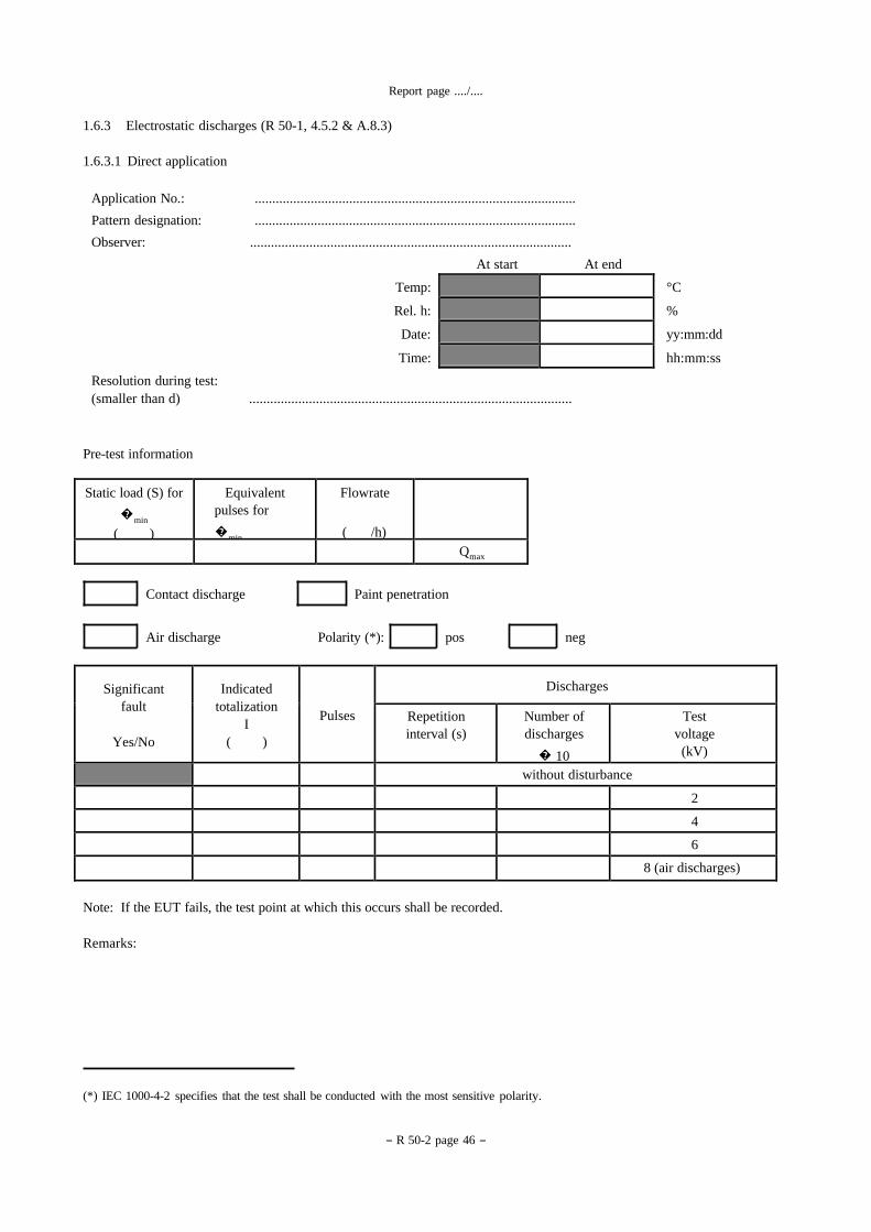
1.6.3 Electrostatic discharges (R 50-1, 4.5.2 & A.8.3)
1.6.3.1 Direct application
Application No.: ............................................................................................
Pattern designation: ............................................................................................
Observer: ............................................................................................
At start At end
Temp: °C
Rel. h: %
Date: yy:mm:dd
Time: hh:mm:ss
Resolution during test:
(smaller than d) ............................................................................................
Pre-test information
Flowrate
( /h)
Equivalent
pulses for
�min
Static load (S) for
�min
( ) Qmax
Contact discharge Paint penetration
Air discharge Polarity (*): pos neg
Discharges
Pulses
Indicated
totalization
I
( )
Significant
fault
Yes/No
Test
voltage
(kV)
Number of
discharges
� 10
Repetition
interval (s)
without disturbance
2
4
6
8 (air discharges)
Note: If the EUT fails, the test point at which this occurs shall be recorded.
Remarks:
(*) IEC 1000-4-2 specifies that the test shall be conducted with the most sensitive polarity.
Report page ..../....
(*) IEC 1000-4-2 specifies that the test shall be conducted with the most sensitive polarity.
- R 50-2 page 47 -
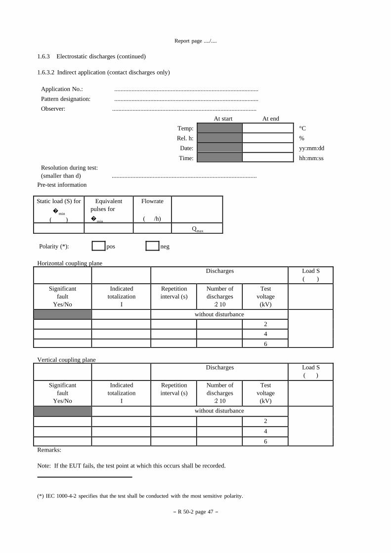
1.6.3 Electrostatic discharges (continued)
1.6.3.2 Indirect application (contact discharges only)
Application No.: ............................................................................................
Pattern designation: ............................................................................................
Observer: ............................................................................................
At start At end
Temp: °C
Rel. h: %
Date: yy:mm:dd
Time: hh:mm:ss
Resolution during test:
(smaller than d) ............................................................................................
Pre-test information
Flowrate
( /h)
Equivalent
pulses for
�min
Static load (S) for
�min
( ) Qmax
Polarity (*): pos neg
Horizontal coupling plane
Load S
( ) Discharges
Test
voltage
(kV)
Number of
discharges
:2 10
Repetition
interval (s) Indicated
totalization
I
Significant
fault
Yes/No
without disturbance 2 4
6
Vertical coupling plane
Load S
( ) Discharges
Test
voltage
(kV)
Number of
discharges
:2 10
Repetition
interval (s) Indicated
totalization
I
Significant
fault
Yes/No
without disturbance
2
4
6 Remarks:
Note: If the EUT fails, the test point at which this occurs shall be recorded.

Report page ..../....
- R 50-2 page 48 -
1.6.3 Electrostatic discharges (continued)
Specification of test points of EUT (direct application), e.g. by photos or sketches
a) Direct application
Contact discharges:
Air discharges:
b) Indirect application
Report page ..../....
- R 50-2 page 49 -
Flowrate
( /h)
Equivalent
pulses for
�min
Static load (S)
for �min
( ) Qmax
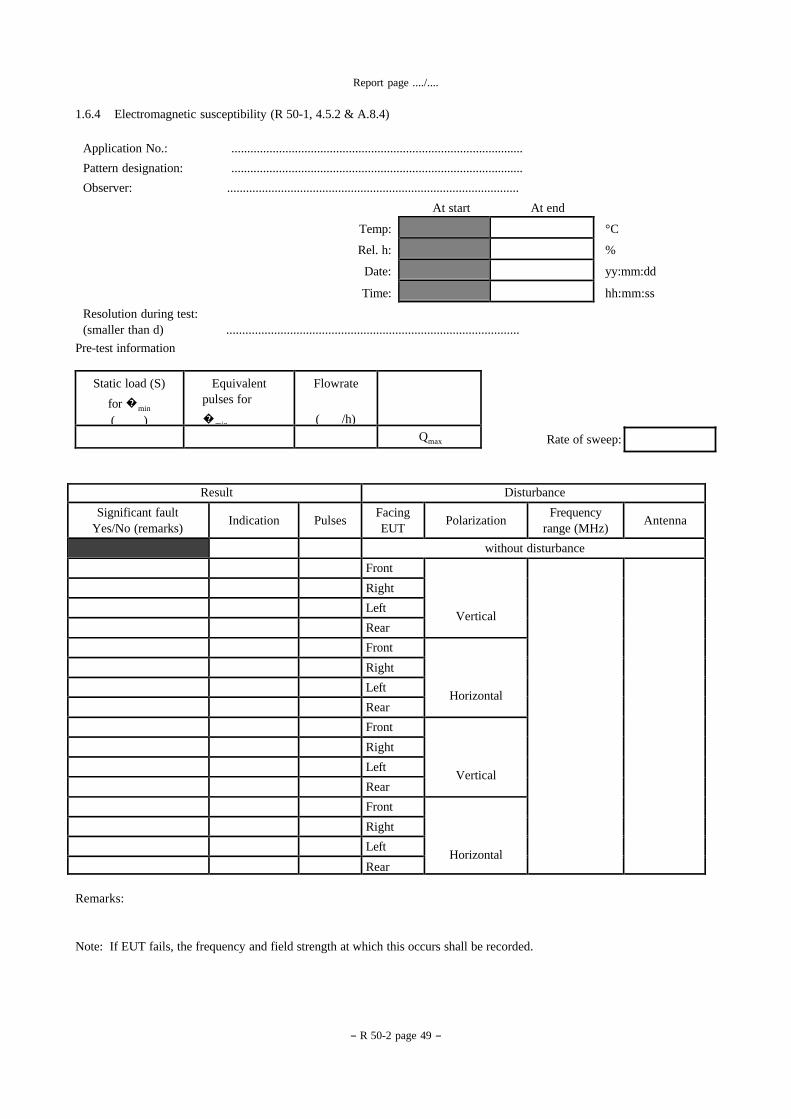
1.6.4 Electromagnetic susceptibility (R 50-1, 4.5.2 & A.8.4)
Application No.: ............................................................................................
Pattern designation: ............................................................................................
Observer: ............................................................................................
At start At end
Temp: °C
Rel. h: %
Date: yy:mm:dd
Time: hh:mm:ss
Resolution during test:
(smaller than d) ............................................................................................
Pre-test information
Rate of sweep:
Disturbance Result
Antenna Frequency
range (MHz)
Polarization Facing
EUT
Pulses
Indication Significant fault
Yes/No (remarks)
without disturbance
Vertical
Front
Right
Left
Rear
Horizontal
Front
Right
Left
Rear
Vertical
Front
Right
Left
Rear
Horizontal
Front
Right
Left
Rear
Remarks:
Note: If EUT fails, the frequency and field strength at which this occurs shall be recorded.
Report page ..../....
- R 50-2 page 50 -
Load S
Pulses
T
Indicated total
Difference
I - I Run 1 I1 Run 2 I2
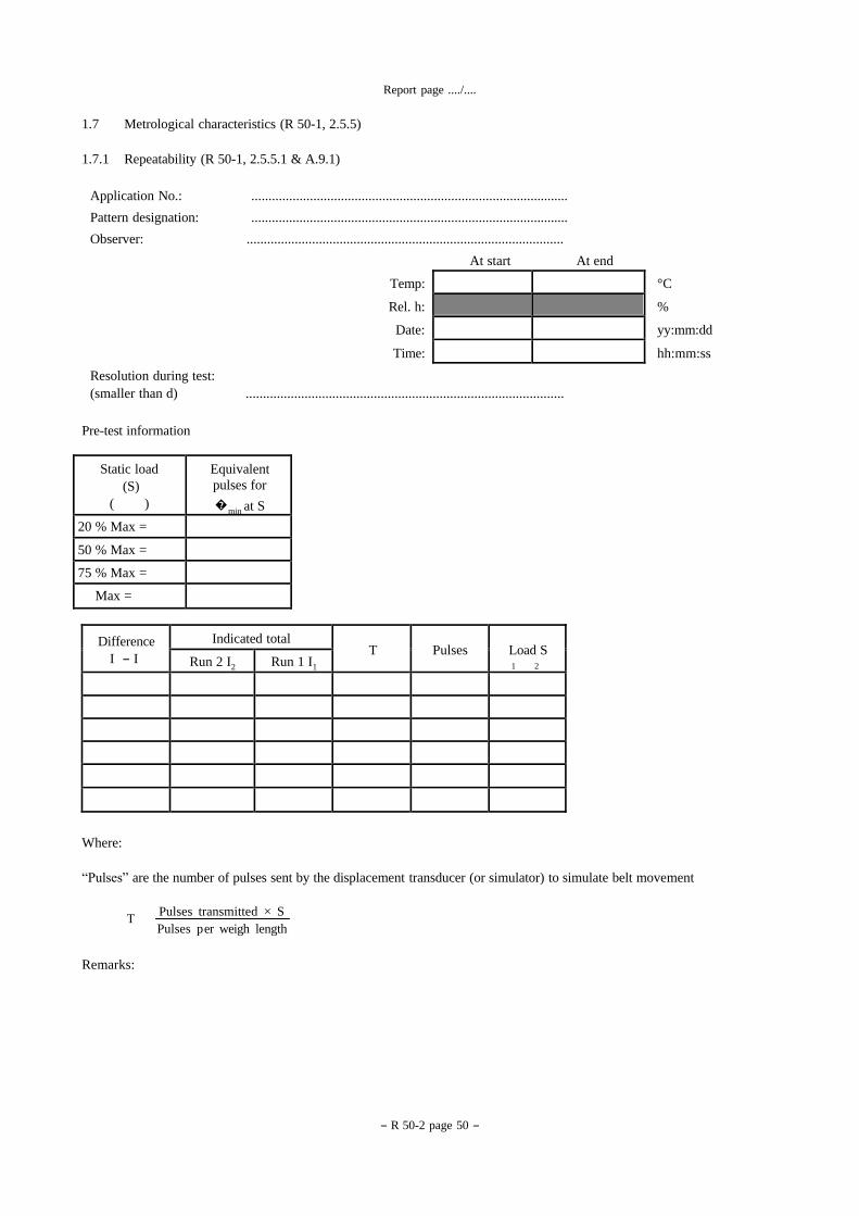
1.7 Metrological characteristics (R 50-1, 2.5.5)
1.7.1 Repeatability (R 50-1, 2.5.5.1 & A.9.1)
Application No.: ............................................................................................
Pattern designation: ............................................................................................
Observer: ............................................................................................
At start At end
Temp: °C
Rel. h: %
Date: yy:mm:dd
Time: hh:mm:ss
Resolution during test:
(smaller than d) ............................................................................................
Pre-test information
Equivalent
pulses for
�min at S
Static load
(S)
( )
20 % Max =
50 % Max =
75 % Max =
Max =
1 2
Where:
“Pulses” are the number of pulses sent by the displacement transducer (or simulator) to simulate belt movement
T Pulses transmitted × S
Pulses p er weigh length
Remarks:
- R 50-2 page 51 -
Report page ..../....
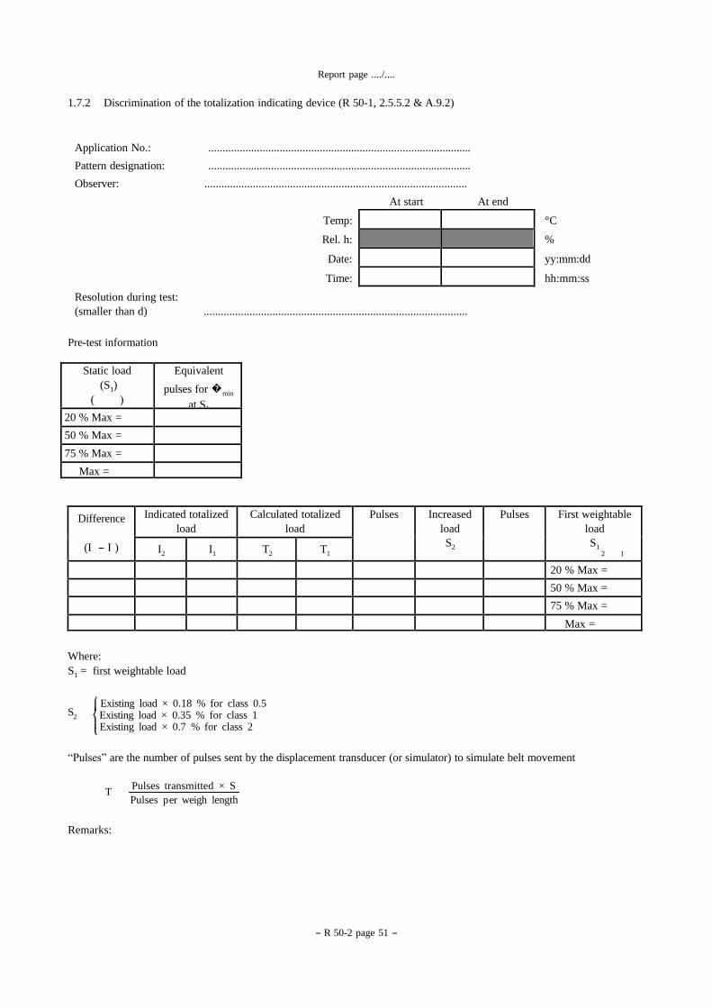
1.7.2 Discrimination of the totalization indicating device (R 50-1, 2.5.5.2 & A.9.2)
First weightable
load
S1
Pulses Increased
load
S2
Pulses Calculated totalized
load Indicated totalized
load Difference
(I - I ) T1 T2 I1 I2
20 % Max =
50 % Max =
75 % Max =
Max =
Application No.: ............................................................................................
Pattern designation: ............................................................................................
Observer: ............................................................................................
At start At end
Temp: °C
Rel. h: %
Date: yy:mm:dd
Time: hh:mm:ss
Resolution during test:
(smaller than d) ............................................................................................
Pre-test information
Equivalent
pulses for �min
at S1
Static load
(S1)
( )
20 % Max =
50 % Max =
75 % Max =
Max =
2 1
Where:
S1 = first weightable load
Existing load × 0.18 % for class 0.5
S2 Existing load × 0.35 % for class 1
Existing load × 0.7 % for class 2
“Pulses” are the number of pulses sent by the displacement transducer (or simulator) to simulate belt movement
T Pulses transmitted × S
Pulses p er weigh length
Remarks:
- R 50-2 page 52 -
Report page ..../....
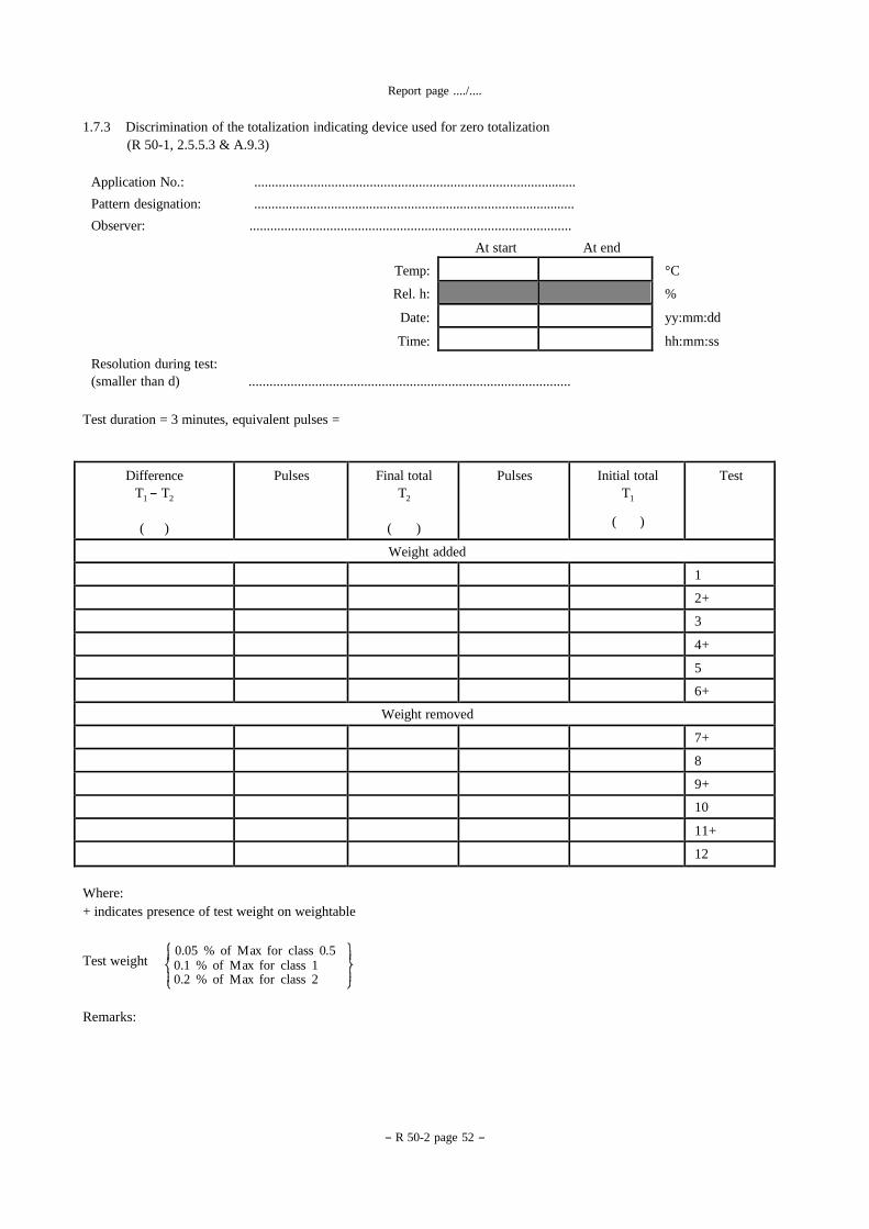
1.7.3 Discrimination of the totalization indicating device used for zero totalization
(R 50-1, 2.5.5.3 & A.9.3)
Application No.: ............................................................................................
Pattern designation: ............................................................................................
Observer: ............................................................................................
At start At end
Temp: °C
Rel. h: %
Date: yy:mm:dd
Time: hh:mm:ss
Resolution during test:
(smaller than d) ............................................................................................
Test duration = 3 minutes, equivalent pulses =
Test Initial total
T1
( )
Pulses Final total
T2
( )
Pulses Difference
T1 - T2
( )
Weight added
1
2+
3
4+
5
6+
Weight removed
7+
8
9+
10
11+
12
Where:
+ indicates presence of test weight on weightable
Test weight
Remarks:
0.05 % of M ax for class 0.5 0.1 % of M ax for class 1 0.2 % of M ax for class 2
- R 50-2 page 53 -
Report page ..../....
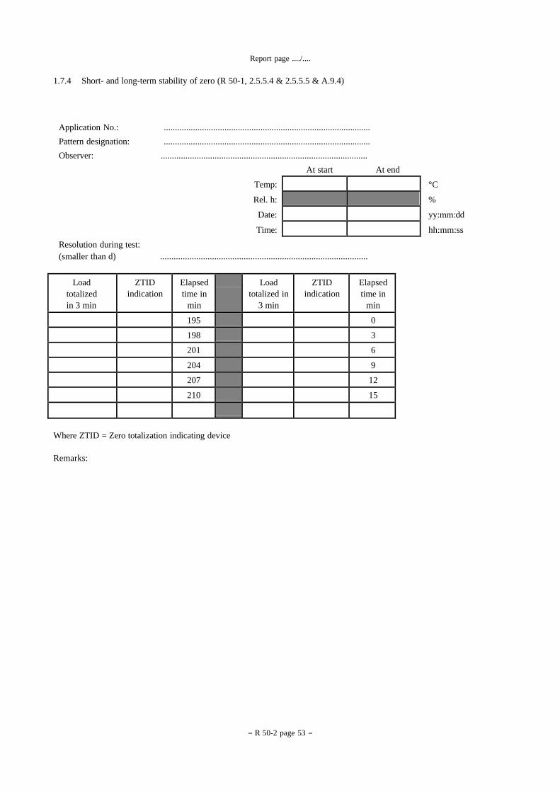
1.7.4 Short- and long-term stability of zero (R 50-1, 2.5.5.4 & 2.5.5.5 & A.9.4)
Application No.: ............................................................................................
Pattern designation: ............................................................................................
Observer: ............................................................................................
At start At end
Temp: °C
Rel. h: %
Date: yy:mm:dd
Time: hh:mm:ss
Resolution during test:
(smaller than d) ............................................................................................
Elapsed
time in
min
ZTID
indication Load
totalized in
3 min
Elapsed
time in
min
ZTID
indication Load
totalized
in 3 min
0 195
3 198
6 201
9 204
12 207
15 210
Where ZTID = Zero totalization indicating device
Remarks:
- R 50-2 page 54 -
Report page ..../....
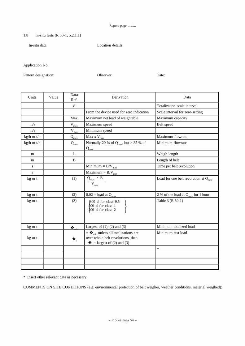
1.8 In-situ tests (R 50-1, 5.2.1.1)
In-situ data Location details:
Application No.:
Pattern designation: Observer: Date:
Data
Derivation Data
Ref.
Value
Units
Totalization scale interval d
Scale interval for zero-setting From the device used for zero indication
Maximum capacity Maximum net load of weightable Max
Belt speed Maximum speed Vmax m/s
Minimum speed Vmin m/s
Maximum flowrate Max x Vmax Qmax kg/h or t/h
Minimum flowrate Normally 20 % of Qmax, but > 35 % of
Qmax Qmin kg/h or t/h
Weigh length L m
Length of belt B m
Time per belt revolution Minimum = B/Vmax s
Maximum = B/Vmin s
Load for one belt revolution at Qmax Qmax
× B
Vmax
(1) kg or t
2 % of the load at Qmax for 1 hour 0.02 × load at Qmax (2) kg or t
Table 3 (R 50-1) 800 d for class 0.5 400 d for class 1 200 d for class 2
(3) kg or t
Minimum totalized load Largest of (1), (2) and (3) �min kg or t
Minimum test load = �min unless all totalizations are
over whole belt revolutions, then
�t = largest of (2) and (3)
�t
kg or t
*
* Insert other relevant data as necessary.
COMMENTS ON SITE CONDITIONS (e.g. environmental protection of belt weigher, weather conditions, material weighed):
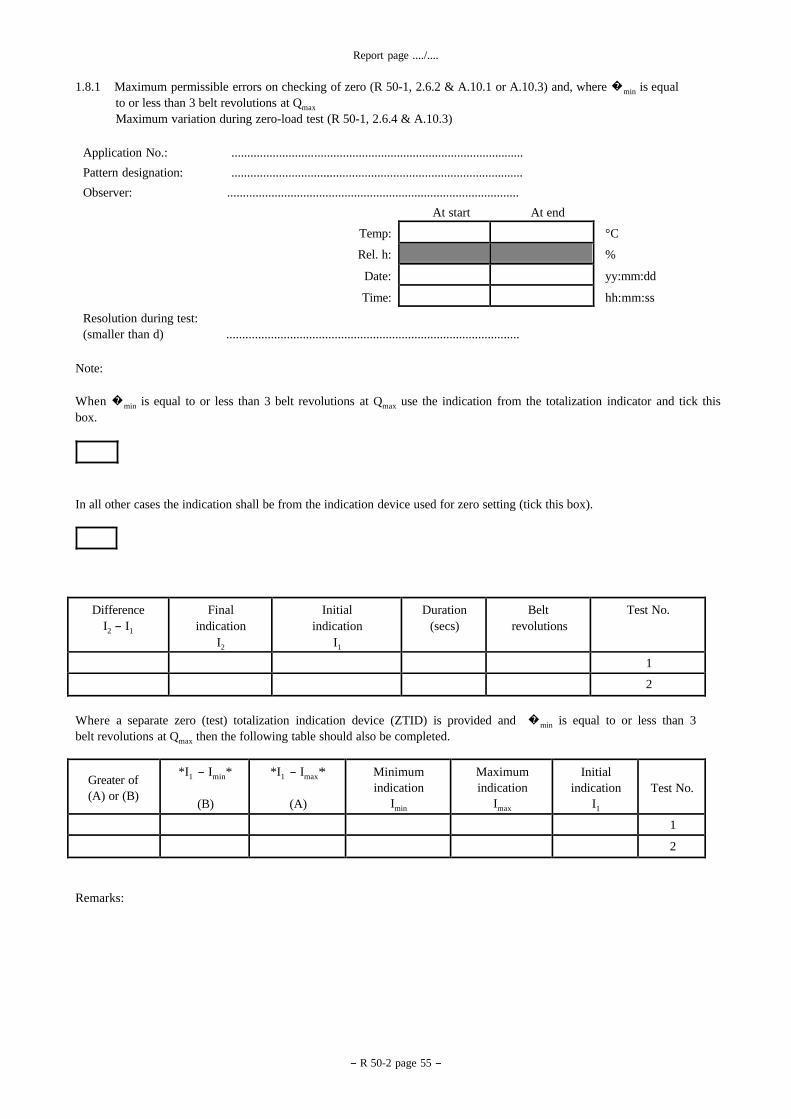
Report page ..../....
- R 50-2 page 55 -
1.8.1 Maximum permissible errors on checking of zero (R 50-1, 2.6.2 & A.10.1 or A.10.3) and, where �min is equal
to or less than 3 belt revolutions at Qmax
Maximum variation during zero-load test (R 50-1, 2.6.4 & A.10.3)
Application No.: ............................................................................................
Pattern designation: ............................................................................................
Observer: ............................................................................................
At start At end
Temp: °C
Rel. h: %
Date: yy:mm:dd
Time: hh:mm:ss
Resolution during test:
(smaller than d) ............................................................................................
Note:
When �min is equal to or less than 3 belt revolutions at Qmax use the indication from the totalization indicator and tick this box.
In all other cases the indication shall be from the indication device used for zero setting (tick this box).
Test No. Belt
revolutions Duration
(secs) Initial
indication
I1
Final
indication
I2
Difference
I2 - I1
1
2
Where a separate zero (test) totalization indication device (ZTID) is provided and �min is equal to or less than 3
belt revolutions at Qmax then the following table should also be completed.
Test No.
Initial
indication
I1
Maximum
indication
Imax
Minimum
indication
Imin
*I1 - Imax*
(A)
*I1 - Imin*
(B)
Greater of
(A) or (B)
1
2
Remarks:
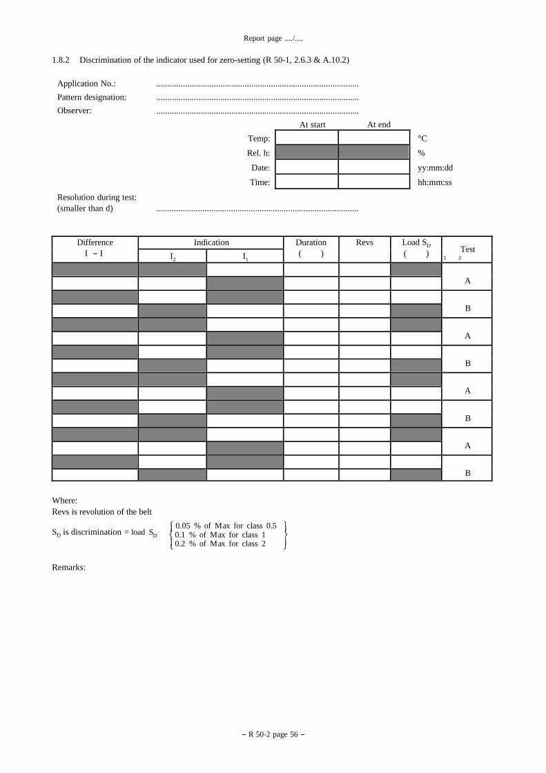
Report page ..../....
1.8.2 Discrimination of the indicator used for zero-setting (R 50-1, 2.6.3 & A.10.2)
Application No.:
Pattern designation:
Observer:
............................................................................................
............................................................................................
............................................................................................
At start At end
- R 50-2 page 56 -
Test Load SD
( ) Revs Duration
( ) Indication Difference
I - I I1 I2
A
B
A
B
A
B
A
B
Resolution during test:
Temp: °C
Rel. h: %
Date: yy:mm:dd
Time: hh:mm:ss
(smaller than d) ............................................................................................
1 2
Where:
Revs is revolution of the belt
SD is discrimination = load S
D
0.05 % of M ax for class 0.5 0.1 % of M ax for class 1 0.2 % of M ax for class 2
Remarks:

Report page ..../....
- R 50-2 page 57 -
2 In-situ material tests (R 50-1, 2.6.1 & 5.1.3.1 & 5.2.1.1 & A.11)
2.1 Accuracy of control instrument (R 50-1, 5.2.1.1 & A.11.1)
Application No.: ........................................................................... Pattern designation: ........................................................................... Scale interval, d: ........................................................................... Maximum capacity: ........................................................................... Minimum capacity: ........................................................................... Observer: ...........................................................................
Resolution during test:
At start At end
Temp: °C
Rel. h: %
Date: yy:mm:dd
Time: hh:mm:ss
(smaller than d) .....................................................................
Control instrument details: Belt weigher details:
Type .................................................... �min ....................................................................
Class ................
Max capacity
....................................
.................................
�t (if different) ....................................................
Where �t is the minimum test load defined in R 50-1, 5.1.3.2.
Min capacity
.................................
Scale interval, dc
.................................
Approval No.
.................................
Transfer vehicle: .......................................
Date of last test
................................
Capacity: .......................................
REQUIREMENT:
The control method used for material tests shall enable determination of the weight of the product used for testing with an
error not exceeding one-third of the appropriate maximum permissible error for automatic weighing in R 50-1, 2.2.1.
Example:
Number of weighings on control instrument
(One gross, one tare for each load)
2 � t N
Vehicle capacity
Number of scale intervals for one
Possible control instrument error
(Class III) per weighing
Vehicle gross load m
dc
± 0.5 dc
for 0 � m � 500
± 1.0 dc
for 500 � m � 2000 Ec
± 1.5 dc
for 2000 � m
Requirement
mpe% × �
× 1/3 � N × E
100 t c
where N is an adjustment for the probable error of N partial weighings.
The metrological authority may want to take into consideration other factors such as journey distance, weather, material loss
on route, etc.
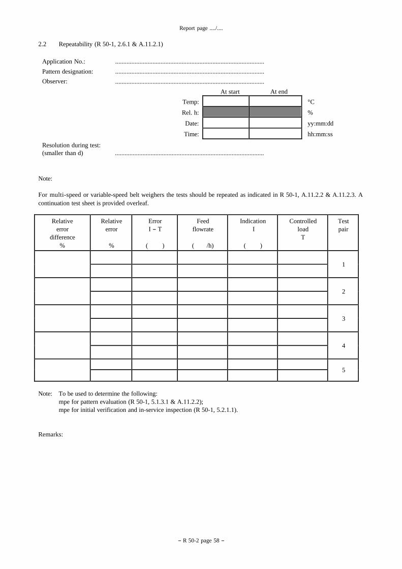
- R 50-2 page 58 -
Report page ..../....
2.2 Repeatability (R 50-1, 2.6.1 & A.11.2.1)
Application No.:
Pattern designation:
Observer:
............................................................................................
............................................................................................
............................................................................................
At start At end
Resolution during test:
Temp: °C
Rel. h: %
Date: yy:mm:dd
Time: hh:mm:ss
(smaller than d) ............................................................................................
Note:
For multi-speed or variable-speed belt weighers the tests should be repeated as indicated in R 50-1, A.11.2.2 & A.11.2.3. A
continuation test sheet is provided overleaf.
Test
pair Controlled
load
T
Indication
I
( )
Feed
flowrate
( /h)
Error
I - T
( )
Relative
error
%
Relative
error
difference
%
1
2
3
4
5
Note: To be used to determine the following:
mpe for pattern evaluation (R 50-1, 5.1.3.1 & A.11.2.2);
mpe for initial verification and in-service inspection (R 50-1, 5.2.1.1).
Remarks:
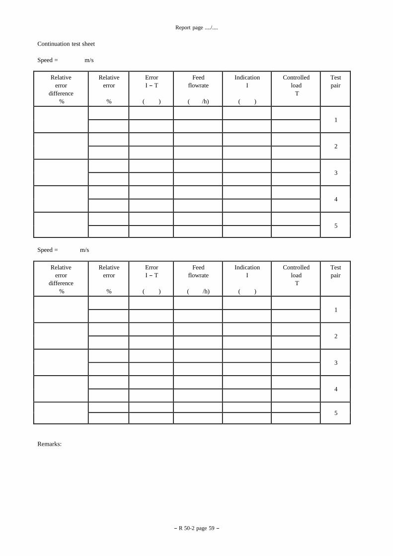
- R 50-2 page 59 -
Report page ..../....
Continuation test sheet
Speed = m/s
Test
pair Controlled
load
T
Indication
I
( )
Feed
flowrate
( /h)
Error
I - T
( )
Relative
error
%
Relative
error
difference
%
1
2
3
4
5
Speed = m/s
Test
pair Controlled
load
T
Indication
I
( )
Feed
flowrate
( /h)
Error
I - T
( )
Relative
error
%
Relative
error
difference
%
1
2
3
4
5
Remarks:


![OIML R 49-1 (E) 2006 - ZEN SERVIS International recommendation OIML R...OIML D 11 ]. OIML R 49-1: 2006 (E) 7 2.2.10 Significant fault Fault, the magnitude of which is greater than](https://static.fdocuments.net/doc/165x107/5add5cf97f8b9a9d4d8d12e1/oiml-r-49-1-e-2006-zen-international-recommendation-oiml-roiml-d-11-oiml.jpg)


![COMMITTEE DRAFT OIML/4 5 CD Date: Oct 2011May …workgroups.oiml.org/tcsc/tc-09/tc-09-sc-02/revision-of-oiml-r-50-1...Evaluation of Measuring Instruments B3:2003 [3], and to the OIML](https://static.fdocuments.net/doc/165x107/5add5cf97f8b9a9d4d8d12b0/committee-draft-oiml4-5-cd-date-oct-2011may-of-measuring-instruments-b32003.jpg)