Office Viewer Manual - powerlogger.com for Viewer 2016.pdf · System Help ... Allows you to import...
35
2016 Office Viewer Manual Suite 200, 638 – 11 th Avenue S.W. Calgary, Alberta T2R-0E2 Phone: (403) 777-9454
Transcript of Office Viewer Manual - powerlogger.com for Viewer 2016.pdf · System Help ... Allows you to import...

2016 Office Viewer Manual
Suite 200, 638 – 11th Avenue S.W.
Calgary, Alberta T2R-0E2 Phone: (403) 777-9454

Office Viewer Manual 2016
Office Viewer Manual, Page 2
Table of Contents Introduction ............................................................................................................................... 3
The Selection Bar… ................................................................................................................ 4 The Status Bar… ..................................................................................................................... 4
File Menu ................................................................................................................................... 5 Connect................................................................................................................................... 5 Disconnect .............................................................................................................................. 5 Open ....................................................................................................................................... 5
How to Sort the Well List ...................................................................................................... 6 How to Query the Well List (By String Search) ..................................................................... 7 How to Query the Well List (By DLS or NTS Survey Systems) ............................................. 8
Close....................................................................................................................................... 8 Import Log/Well ....................................................................................................................... 8 Print Log................................................................................................................................ 10 Print Setup ............................................................................................................................ 14 Exit ........................................................................................................................................ 14
Edit Well ................................................................................................................................... 15 Det. Lith Button: ................................................................................................................. 16 Abstract Button .................................................................................................................. 16 Curve Button ..................................................................................................................... 16 How to Change the Digital Curve Attributes (Curve Units, Depth Units, Null Value and Remarks)........................................................................................................................... 16 How to Delete a Well ......................................................................................................... 17
View Menu ............................................................................................................................... 17 Go To Depth.......................................................................................................................... 17 Log Scales ............................................................................................................................ 18 Screen Accuracy ................................................................................................................... 19 Show/Hide Header ................................................................................................................ 20 Show/Hide Digits ................................................................................................................... 20 Status Bar ............................................................................................................................. 20
Options Menu .......................................................................................................................... 21 Refresh Window .................................................................................................................... 21 Refresh Data ......................................................................................................................... 21 Lithology Integrity Check ....................................................................................................... 21 Use Default Printer Settings ................................................................................................... 22 System Options ..................................................................................................................... 22 General Tab .......................................................................................................................... 22 Fonts Tab .............................................................................................................................. 23
How to Set your Fonts ....................................................................................................... 24 How to restore the System default Fonts ............................................................................ 25
Display Tab ........................................................................................................................... 26 Window Menu .......................................................................................................................... 30
Cascade ................................................................................................................................ 30 Tile ........................................................................................................................................ 30 Arrange Icons ........................................................................................................................ 30
System Help ............................................................................................................................ 30 Index: .................................................................................................................................... 30 Using Help:............................................................................................................................ 30 About Power*Log / Core & Curve:.......................................................................................... 31 Context Sensitive Help button: ............................................................................................... 31
Database Management ............................................................................................................ 31 Database Management – How to Change your Password ...................................................... 31 Database Manager – How to Compact / Repair your PowerSuite Database. .......................... 33 Database Manager – How to Backup your PowerSuite Database. ......................................... 34

Office Viewer Manual 2016
Office Viewer Manual, Page 3
Introduction Power*Log / Core & Curve™ (Petrographical Office and Wellsite Evaluation and Reporting) is a chip sample and core logging program that utilizes single-entry data capturing to produce geological striplogs and corelogs. The geological data is entered into the system through the use of intuitive data entry forms to ensure standardization of data. This data is stored in an RDBMS(Relational Database Management System) to allow data manipulation using SQL (Structured Query Language) access tools.
Power*Log & Curve™ Software consists of Four (4) Main Sections: 1. A log editor module that allows you to change the striplogs to suit your needs and
preferences.
2. A data transfer module.
3. Report printing modules.
4. An on-line help system that is designed to familiarize you with the commands and functions available in Power*Log / Core & Curve™ and lead you through many of the processes involved in creating logs.
Starting Power*Log & Curve™…
1. Double click on the Power*Log & Curve™ icon. This brings you into the Power*Log & Curve™ program. The first window to appear will be the Security window with the
registration and copyright information. Click on the button to acknowledge the window. A Connect Database window will immediately appear. See the “Connect” section, later in this User Manual to learn more about how to connect to a database.
2. Highlight the Pgeology VWR Metric 2016 or Pgeology VWR Imperial 2016 (Microsoft Access Driver [*.mdb]) database by clicking on it once, if it is not already highlighted. The choice for metric would be logging in Meters and Imperial would be logging in feet and inches.
3. Move your mouse pointer to the User ID data field and click once to activate a flashing cursor in the User ID field. Then, type pgeology in the User ID field. Press the Tab key on the keyboard.
4. Type pgeology in the Password field and then click on the button. The program will now load various dictionaries and will activate an Open Log window.

Office Viewer Manual 2016
Office Viewer Manual, Page 4
5. Scroll through the well list and Click on a well and then Double click on a log to open a log. You are now in the Power*Log or Curve™ viewer environment.
Accessing the On-line Help System in Power*Log & Curve™: You can make use of the context sensitive help by pressing the F1 key when you are in a dialog box. A pertinent help file will appear, opened to the topic relevant to the dialog box you are in.
The Selection Bar…
Metric Version of the Selection Bar
Imperial Version of theSelection Bar Using USA style Inches Screen Scale
Imperial Version of the Selection Bar Using the Ratio Scales selected in the System Options for Screen Scale
The Status Bar…
The Status Bar displays system status messages and any error message (associated with a field entry), in the far left corner. The KB elevation is displayed in the lower right corner of the Status Bar. The Four (4) Main On-line Help System Categories:
Commands - Descriptions of each menu command within Power*Log / Core & Curve™. Toolbar - Shortcuts to common commands are explained. Database Table Operations - Commands or functions related to the Database Table are described. Quick Reference Guide - The portion of the On-line Help System that quickly refers you to some of the more commonly performed tasks
Office Viewer Manual 2016
Office Viewer Manual, Page 5
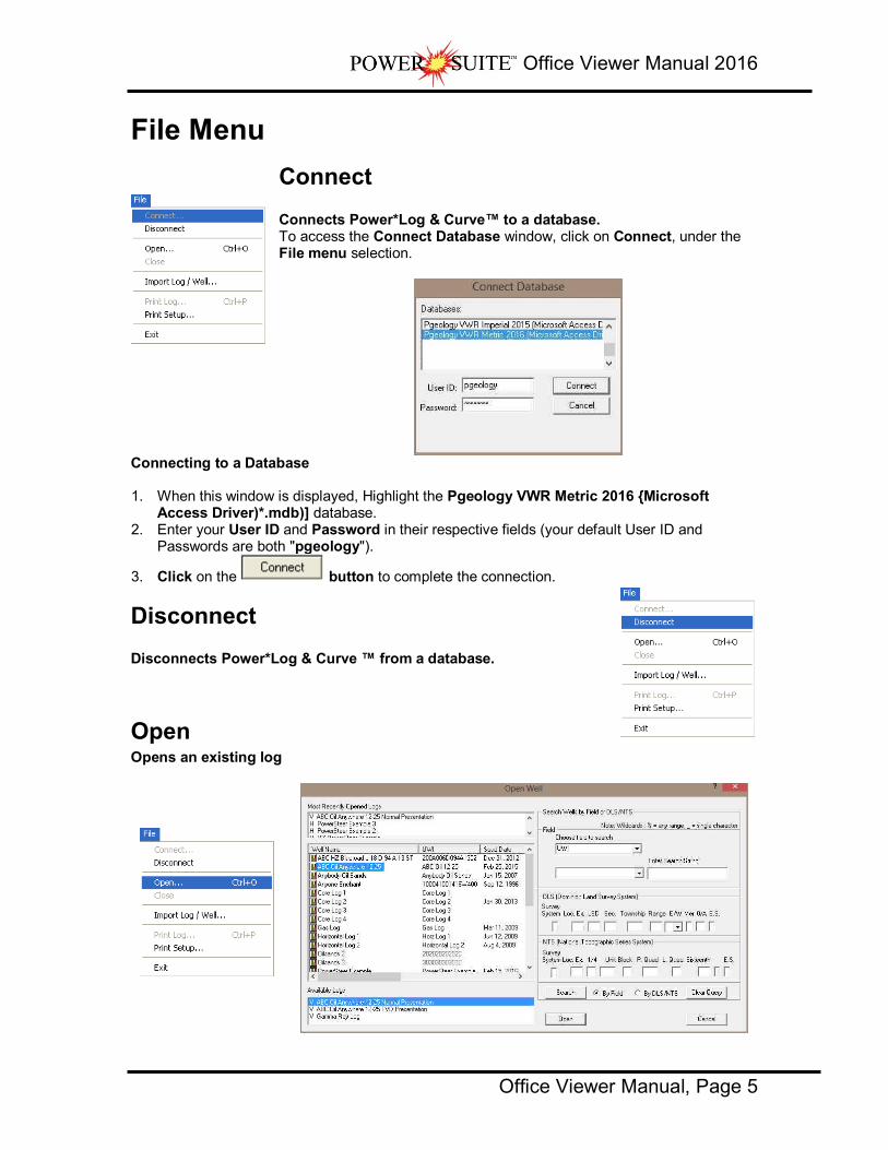
File Menu
Connect Connects Power*Log & Curve™ to a database. To access the Connect Database window, click on Connect, under the File menu selection.
Connecting to a Database 1. When this window is displayed, Highlight the Pgeology VWR Metric 2016 {Microsoft
Access Driver)*.mdb)] database. 2. Enter your User ID and Password in their respective fields (your default User ID and
Passwords are both "pgeology").
3. Click on the button to complete the connection.
Disconnect Disconnects Power*Log & Curve ™ from a database.
Open Opens an existing log

Office Viewer Manual 2016
Office Viewer Manual, Page 6
1. Locate the well you wish to open either by querying or scrolling through the Well List portion of the window and Click on the Well Name so it becomes highlighted, and the logs available for that well will appear in the Log List portion of the window.
2. Click on the log name you want to open. It will become highlighted.
3. Click on the button and the selected log will open accordingly. Please keep in mind that Power*Log & Curve™ allows you to have multiple logs open at once.
The Recent Logs portion of the window indicates the last 10 logs / wells opened. You may wish to select one of these rather than looking through the well list. Also if you are reopening the last well used it is already highlighted in the Recent Logs list and can be reopened easily by clicking
on the button or by depressing your enter key on your keypad.
Note: Logs with the letter "V" in front of their names are Vertical logs, and can only be used within Power*Log™. Likewise, Logs with the letter "H" in front of their names are Horizontal logs, and can only be used within Power*Curve™. We have now shown only the Vertical Logs available in Power*Log and will only show the Horizontal Logs in Power*Curve. This is an ini setting and can be changed in the pgeology.ini file in the installed folder.
How to Sort the Well List (Well Name, UWI, Spud Date, Total Depth, Field, Pool, Hole Direction, Province/State, License #) 1. Select Open, under the File menu selection, to activate the Open Log window.
2. The default sorting in the Open Log window is on Well Name. If you wish to sort on any other
criteria, you simply have to click on its heading indicator at the top of the Well List. By doing so, you will sort the window with respect to that criterion. The Example above is sorted by spud date in ascending order. If you click on the heading indicator again it will reverse the order as shown in the example below with Spud date in descending order.

Office Viewer Manual 2016
Office Viewer Manual, Page 7
How to Query the Well List (By String Search) 1. Select Open, under the File menu selection, to activate the Open Log window.
2. Choose the field to search criteria by clicking on the drop arrow in the search portion of the
window. This will activate a drop list and click on your selection. You have many field strings to search with. Then type in your search criteria in the Enter String field. The example shown above is any Well Name with ABC in it anywhere.
3. You can choose a search type in the drop box beside the Search string you have type or selected. The default is like so if in this case the ANY can be anywhere in the well name.
4. Click on the button. This will redo the Well List with those Well Names that meet the specific criteria. The search results are shown below.
5. Click on the button to refresh the list with all the Wells in the database.

Office Viewer Manual 2016
Office Viewer Manual, Page 8
How to Query the Well List (DLS or NTS Survey System) 1. Select Open, under the File menu selection, to activate the Open Log window.
2. Type in the fields to search by utilizing either the DLS or NTS Survey system that was used to create the UWI. The example shown above is Township 14 Range 16 and the 4th Meridian
3. Click on the button. This will redo the Well List with those Well Names that meet the specific criteria. The search results are shown below.
4. Click on the button to refresh the list with all the Wells in the database.
Close Closes the currently active log Click on Close, under the File menu selection, to close the current or active well.
You can also close a document by clicking once on the icon located at the top right of the document window.
Import Log/Well Allows you to import a PowerSuite Export file (*.exp) into your database 2016 Viewer will only accept Version’s 11, 12, 2015 and 2016 Export files. 1. Select Import Log / Well, under the File menu selection.

Office Viewer Manual 2016
Office Viewer Manual, Page 9
Importing a Log/Well…
1. Click on the button to browse through your drives/directories for the file(s) you wish to import. Note that files available for importing will have an .EXP file extension. Any of the files that you select will then be added to the File list. Please make sure that the files you wish to import are highlighted (selected), in the list prior to importing.
Note: In situations where numerous Export files are all being imported at once, click on the
button to highlight all of the Export files displayed in the Import window.
2. If any of the files are encrypted, a window will appear, stating that the file format is not
recognized (if the files are not encrypted, proceed to Step 5). Click on the button in this window and a Password box will then appear with the filename and an empty field for you to enter the correct Password into.
3. Type in the Password, using UPPERCASE letters only.
4. After entering the Password, click on the button to decrypt the file and place it in the File list with the file's contents displayed in the File Header list field.
5. The Import Log/Well window will now be displayed with the details of the file(s) to be
imported. Select/highlight the file(s) to be imported. Use the button to select all of the
files or use the button to select none of the files. Note that you can select or turnoff individual files by simply clicking on them with your mouse.
Note: The button will remove the selected/highlighted files from the import list,
but will not delete them. The button, on the other hand, will completely erase the selected/highlighted files from their directory. Once deleted, these files will no longer be recoverable.
6. Click on the button to activate the following system message, “Do you really want to IMPORT the highlighted files?”

Office Viewer Manual 2016
Office Viewer Manual, Page 10
7. Click on the button to proceed with the import.
Note: If you click on the “Yes” button, and the file you are importing contains the information from an Entire Well, the following system message will be activated, “About to IMPORT ENTIRE WELL data. All information associated with this well in the database will be OVERWRITTEN. Continue?”
8. Click on the button. 9. Upon completion of the import, the following system message will then be activated, “Data
has been imported successfully.”
10. Click on the button to confirm the successful import of the data.
Print Log Prints all or part of your log/well along with the Title page, legends, individualized cores and formation tops on a continuous or single sheet basis 1. Under the File menu selection, click on Print Log to activate the Print Log window shown
below:
Note: The Title bar and all depths associated with the Print Log window are defaulted to the Depth View that Power*Log is in at the time of the activation of the Print Log window.

Office Viewer Manual 2016
Office Viewer Manual, Page 11
2. Select the appropriate paper orientation from this drop box field and the Title Page, Legend, and Formation Tops will automatically conform to the selected orientation. There are four (4) types of paper orientation to choose from: letter portrait or landscape and legal portrait or landscape settings.
Note: The letter or legal landscape or portrait settings selected from within the Print Log window will NOT override the paper orientation settings selected in the printer's Properties window. Therefore, you must also modify the paper orientation settings in your printer's Properties window to letter or legal landscape.
3. Activate this check box , if you wish to printout a full Wellsight Version of the Title Page.
4. If you are printing the Striplog Title page and you are in Alberta the EUB format should be selected.
5. Activate this check box , if you wish to printout an abbreviated version of the Core Log Title Page.
6. Activate this check box , if you wish to printout an abbreviated version of the Core Log alternate title Page.
7. Activate this check box , if you wish to printout an abbreviated version of the Sample Log Title Page.
8. Activate this check box , if you wish to printout a logo, and then select
a logo from the Logo drop box field.
Note: Any bitmap image may be printed out as a logo. However, the bitmap image must be an equally sided square image, because Power*Suite will shrink or expand the image to fit the logo space on the Title Page. This bitmap should be placed in the Powersuite_V9\logo directory.
9. Activate this check box , if you wish to printout a location map following the title page, and then the user select
a location map from your computers drives by clicking on the and finding the file you want to print out as a location map.
Note: This must be a bitmap image file (*.bmp) if you want a location map to be printed out. Also, the bitmap image must be a square image, because Power*Suite will shrink or expand the image to fit the location map space following the Title Page. This bitmap can be placed anywhere as the file location is saved within the Power*Suite ini file.
10. Survey views Activate this check box , if you wish to have the plan view (view of the well bore from surface) printed out in the striplog header as captured in the Survey View application.
11. Survey views Activate this check box , if you wish to have the user defined view (view of the well bore as manipulated by the user) printed out in the striplog header as captured in the Survey View application.
12. Survey views Activate this check box , if you wish to have the azimuth view (view of the well bore along the target azimuth) printed out in the striplog header as captured in the Survey View application.
13. Survey views Activate this check box , if you wish to have the cross section view (view of the well bore at right angles to the target azimuth) printed out in the striplog header as captured in the Survey View application.
14. Survey views Activate this check box , if you wish to have all the views printed out in the striplog header as captured in the Survey View application.
15. Activate this check box , if you wish to have our entire legend printed out.

Office Viewer Manual 2016
Office Viewer Manual, Page 12
16. Activate this check box , if you wish to have the legend reflect only the symbols printed on the log or core portions of the printed intervals defined in the log and core portions of the print log window.
17. Type any pertinent comments into the Title Page Remarks field and they will be displayed accordingly on the Strip Log Title Page only.
18. Activate this check box , if you wish to have our entire legend printed out. 19. Activate this check box , if you wish to have the legend reflect only
the symbols printed on the log or core portions of the printed intervals defined in the log and core portions of the print log window.
In the Log portion of the Print Log window
1. Select or type in the Scale for the main log to be printed out at, in the Scale drop box field.
2. Activate this check box to have the track headers printed out with the main log. 3. Activate this check box to have the track footers printed out with the main log. 4. Activate this check box to have the core accessories printed out on the
main log. 5. Highlight the main log printing options in the selection
box. The user can select either None, User-defined Interval (requires that you manually enter the desired print interval depths), Today Section, Well Section, or Lithology Section.
Note: Today Section interval is derived from the From and To Depth values entered into the Today’s Section portion of the Power*Log Data Transfer: Export window.
The Well Section interval is derived from the Top and Base Depth values entered into the Print Sections window under the Edit pull down menu. (see Print Sections).
The Lithology Section interval is derived from what has been drawn into the interpretive lithology track of the well that is being printed.
If user defined interval is chosen the user can select which depth type, either measured depth, true vertical depth or subsea level depth from the depth measurement drop box. The user must also type in the depth interval to be printed.
Note: The log itself must be displayed in whatever depth view you wish to print before you activate the print log window. To change the log to the desired format, refer to depth view under the view pull down menu.
In the Cores portion of the Print Log Window
1. If you are printing out a Core log on the tail of the striplog, select the Cores you wish to print by highlighting them.
2. Select or type in the Scale for the core log to be printed out at in the Scale drop box field.
3. Activate this check box to have the track headers printed out with the core log. 4. Activate this check box to have the track footers printed out with the core log.
Note: A separate Header Information Box is automatically printed out with every Core and includes the Core Scale, Core Date, Core Number, Cored Interval, Amount Cut, Amount Recovered, and Percentage.
**A value must be entered into the Core Scale field in order to printout anything. **
5. Activate this check box if you wish to printout Formation Tops and the Formation Tops will be included on a separate page at the end of the log printout.

Office Viewer Manual 2016
Office Viewer Manual, Page 13
The page margin field is available, primarily, when you are printing to Adobe Acrobat writer. When a numerical value in inches is typed into this field it will initiate a top and left margin for the templates (Title Page, Legend and Formation Tops) as well as a left margin for the main log.
Activate this check box if you are printing on single sheets. This will force the printer to include an additional 1/4 inch of the log at the top and bottom of each page, so that you can cut-and-paste pages manually, if you so desire. Default Activating the default radio button forces Power*Log / Core & Curve to use a raster
or bitmap graphic printing method. This printing method is generally used with Laser printers but not exclusively so. Meta File Activating the Meta File radio button forces Power*Log / Core & Curve to use the meta file technology printing method. This printing
method was developed for the newer models of printers on the market today as well as using the Adobe Acrobat Distiller or pdf printing technology. Auto Activating the Auto radio button forces Power*Log / Core & Curve to use the settings
from the printer driver to printout the log. Color Activating the Color radio button forces Power*Log / Core & Curve to override the printer driver settings and consequently Power*Log / Core & Curve assumes that you are using a color printer.
Mono Activating the Mono radio button forces Power*Log / Core & Curve to override the printer driver settings and consequently Power*Log / Core & Curve assumes that you are using a monochrome (black and white) printer.
6. Click on the button to activate the Print Setup window and confirm that the correct printer settings are in effect.
Note: If you are printing out logs in color, you must activate the Diffusion or Error Diffusion option normally found under Graphics in the Properties window for most printers.
7. Interval per page field indicates how many meters of log will fit on a page of selected paper size and orientation selected in the setup as well as what log scale you are printing at. This will help indicate to the user how many pages will be required by the print job.
8. Activate this check box if the user wishes to have a blank page before the logs starts. This could be useful if utilizing continuous paper when you want the title page oriented on the correct side of the prefolded paper.
9. When you are ready to print your log, click on the button.
Note: If you do exit from the Print Log window, you will be asked if you wish to save the print settings. If you click on Yes, the program will remember every setting that you made to the Print Log window and then will default to those settings the next time you enter the Print Log window

Office Viewer Manual 2016
Office Viewer Manual, Page 14
Print Setup This command allows you to customize your printer options. Click on Print Setup, under the File menu selection, to activate the Print Setup window shown below:
1. If you wish to use a printer other than the default printer, then select an available printer from
the drop down menu. 2. Define the Paper Orientation by selecting either the Portrait or Landscape radio button . 3. Select a Paper Size(generally Letter 8.5 x 11), and Source from the appropriate drop boxes.
4. To modify settings that are specific to the printer, click on the button.
Note: All reports are printed out in Portrait(Letter 8.5 x 11), however, logs may be printed in any format you wish.
5. If you are printing the log in color, then select Diffusion or Error Diffusion, under Dithering, via the Graphics tab from within the printer's Properties window. Conversely, if you are printing the log in black & white, then select Coarse, under Dithering, via the Graphics tab from within the printer's Properties window. Moreover, select Print True Types as Graphics via the Fonts tab from within the printer’s Properties window, regardless of whether you are printing in black & white or color.
Exit Closes current logs/wells, closes Power*Log / Curve / Core™, and returns to the Windows Desktop. Click on the Exit selection located under the File menu selection, to exit from Power*Log / Curve / Core applications. Shortcut:
Click on the shown below, at the far right of the Title Bar

Office Viewer Manual 2016
Office Viewer Manual, Page 15
Edit Well Lets you edit existing wells, and delete a well. The majority of this information is usually filled in at the start of a well, but should be updated with new information at the completion of a well. The information associated with each well is entered into the Well window, along with the well's UWI (Unique Well Identifier). Note that each well and the information that it contains must be associated with a UWI (Unique Well Identifier) in order to distinguish it from the other wells residing within the Power*Log / Core & Curve database. However, the only way in which a well’s information can then be displayed is by associating it with a log and then having that log open.
Click on Well, under the Edit menu selection, to activate the Well window.
Note: The well window has been filled in to give you an idea of how to complete the different fields.
1. Change or add to the different fields by typing in the fields. Certain fields have restrictions to what data they accept. If an error occurs while saving refer to the status bar for instructions.
2. Click on the button or press ALT-S and the well data that you have just entered will be saved to the database.

Office Viewer Manual 2016
Office Viewer Manual, Page 16
Note: The Well Name field should be highlighted after you have clicked on the button or press ALT-S, as an indication of a properly saved record. Some of the fields in the Edit Well window have character restrictions or mandatory requirements. Consequently, if any of these restrictions have been violated or if any requirements have not been met, the offending field will be highlighted and the problem will be displayed on the Status Bar, at the lower left hand corner of your screen. Remember to save your work again, after the problem has been rectified.
3. If the record has been successfully saved, click on the button, when prompted with the Shortcut Options system window.
Det. Lith Button:
1. The Detailed Lithology button allows you to add Detailed Lithology Groups. This is not applicable to the Office Viewer
Abstract Button This button allows you to access the Well Abstract window, so that you may document an overview or maybe important facts regarding the well. This is not applicable to the Office Viewer.
Curve Button
The button activates the Digital Curve window and the user can edit the curve attributes as well as get at a secondary window to edit or view the curve scales. There are only two ways to change the Curve Attributes. One is through the Layer Configuration window and the other is Well Window and is located under the Edit pull down menu
How to Change the Digital Curve Attributes (Curve Units, Depth Units, Null Value and Remarks)
1. Click on the button in the lower right corner of the Well of the window. This will activate Digital Curve window. The user can also right click on an active curve layer and select the Edit Curve selection.
2. The Default Curve name will be the curve name first in the Alphabet. The user can click on
the button to see a list of the curves associated with the primary well. 3. You can now rename, or type in, new units, change the null value, or add/change the
remarks.
4. Click on the button or press ALT-S. The user can also change the curve scales by
clicking on the button and editing the curve scales here.

Office Viewer Manual 2016
Office Viewer Manual, Page 17
How to Delete a Well 1. Click on the Edit menu selection and Click on Well to activate the Well window.
2. Click on the button to activate the Well List window.
3. Double Click on the well name you wish to delete and its attributes will be displayed in the
Well window. Or click on the well name so that it goes into the upper field and click on the
button.
4. Click on the button and a confirmation message will appear asking, "Would you like to delete the current record?"
5. Click on the button to delete the well from the Well List and from the database.
View Menu
Go To Depth This allows you to go to a specific depth on the active log. There are two ways to do this procedure, as listed below: Procedure 1 1. Click on Go to Depth, under the View menu selection, to activate the Go to Depth window
for the active log.
2. Type in a depth in the depth field and then click on the button. This will place the depth specified at the top of the screen in Power*Log/Core or the left of your screen in Power*Curve.

Office Viewer Manual 2016
Office Viewer Manual, Page 18
Procedure 2 1. Click in the Go to Depth field. 2. Type in the depth of the log that you wish to view, in the Go to Depth field.
3. Once you have entered the desired depth, press the Tab key to exit from the Go to Depth
field and the depth that you entered will then be displayed at the top of the log.
Log Scales Allows the user to change the depth scale of the active log. Screen Log depth scales can be chosen from the menu and can also be type in the second method. The screen depth scales vary from 1:1 to 1:5000. There are two ways to do this procedure. They are both outlined below.
Procedure 1
Click on Log Scales, under the View menu selection, to activate the pop out menu and then click on the log scale you want for the active Log. This will refresh your log with the new Scale.
Metric Version
Imperial Version

Office Viewer Manual 2016
Office Viewer Manual, Page 19
Note: This list is a partial list of the scales that can be displayed. To get the ability to display the log at any scale between 1:1 and 1:5000 refer to Procedure 2.
Procedure 2 1. Click in the Log Scales field. 2. Select a scale from the list by clicking on it, or by typing in a scale in the Log Scales field.
3. Depress the Tab key on your keypad. This will refresh your log with the new Log Scale.
Screen Accuracy Varies the depth increment of the log according to your specifications. This increases or decreases the accuracy of your mouse pointer, while locating more specific depths with your mouse. There are two ways to do this procedure. They are both outlined below. Procedure 1 1. Click on Screen Scale Accuracy, under the View menu selection, to activate the pop out
menu and then click on the screen scale accuracy you want for the active Log. This will change the mouse’s accuracy.
Procedure 2 1. Click on the Screen Accuracy field to activate the drop down menu.

Office Viewer Manual 2016
Office Viewer Manual, Page 20
2. Select an available increment from the Screen Accuracy drop down menu by clicking once
on the desired increment and your selection will be displayed within the Screen Accuracy field accordingly.
Show/Hide Header Toggles between displaying the Header and removing it from the viewing area Click on Show/Hide Header, under the View menu selection, or
click on the Show/Hide Header button on the Toolbar.
Show/Hide Digits This function will either display or hide digits from the grid of an active curve layer on your log. Click on Show/Hide Digits, under the View menu selection, or click
on the Show/Hide Digits button on the Toolbar.
Note: This function only works for Curve layers on the log.
Status Bar Turns the Status Bar, located at the bottom of the Power*Log / Core & Curve™ screen, on and off. This is the Power*Log / Core & Curve™ Status Bar… The Status Bar displays system status and any error messages in the lower left corner of the screen. If there are no errors the status bar will indicate "For Help, press F1".
Note: The KB Elevation is displayed in the lower right corner of the Status Bar

Office Viewer Manual 2016
Office Viewer Manual, Page 21
Options Menu
Refresh Window When you click on Refresh Window, under the Options menu selection, Power*Log & Curve will redraw the layers displayed on the screen. This is utilized to redraw the log when the screen doesn't look normal. This option will not retrieve information from the database and populate the log with it.
Note for Network users: Since this function doesn't retrieve information from the database, you will not be able to see any changes made by other network users.
Refresh Data This option updates the log/well with all of the new/updated data that has been edited, entered or imported into the database. It can also be used if you have made some changes and you don't believe that they are being reflected on the log. Refresh Data is particularly helpful, when you are working on numerous logs with the same Primary Well and the current log has been updated, while the inactive log(s) have not. To update the inactive log(s) with the latest information, make one of the
previously inactive logs active, click on the Refresh Data option, and then repeat this procedure for the rest of the logs.
Note: If you are using a network version of Power*Log & Curve, the Refresh Data option will update the database with changes, that have been made to the same Primary Well by another workstation.
Lithology Integrity Check This option is used to verify the integrity of the lithologic intervals. This makes sure that there are no overlapping intervals on the log or in the database.
Checking and Fixing Lithologic Integrity 1. Click on Lithology Integrity Check, under the Options menu selection, to activate the
Lithology Integrity window, which will default to the active well.

Office Viewer Manual 2016
Office Viewer Manual, Page 22
2. If necessary, click on the button and select the well that you wish to check or fix.
3. Click on the button and Power*Log & Curve will then check for integrity errors
and display a message box showing the number of errors found. Click on the button to acknowledge the message.
4. If there are any errors that you wish to fix, click on the button to activate a system message which allows you to verify the deletion of the offending intervals.
5. Click on the button to delete the intervals or click on the button to cancel the operation.
Note: If you have fixed any intervals (deleted them), you will have to re-populate the log with the correct interpretive lithology.
Use Default Printer Settings Occasionally the Power*Suite printer settings gets confused in the initialization file and the user cannot activate either the Print Log window or the Printer Setup windows in the Morning and Well End report print windows. This problem can be rectified by clicking on the Use Default Printer Settings and clicking on yes to the ensuing message.
System Options The user can manage Power*Log and Power*Curve system settings with this tab dialogue window. Once you have made
your changes Click on the button
General Tab

Office Viewer Manual 2016
Office Viewer Manual, Page 23
Home Directory - This is the directory on your hard drive where Power*Log and Power*Curve is being executed. The user will not see any symbols on their log or print out any of our reports it you have the wrong home directory.
This check box when activated will populate the Open Log window with all the wells in the database. If it is unchecked it may help our corporate users and the time it take to retrieve thousands of wells from the database and to populate the Open Log window with that information. If this check box is deactivated and you wish to see all your wells then simply
click on the button in the Open Log window to see all their wells if this option is deactivated.
Date Format - From this drop box, you can select the date format. This selection determines how every date in Power*Log / Core & Curve will be entered and displayed. If you import a log with different date formats, Power*Log / Core & Curve will change the dates to comply with the format you've chosen here. The user can change this at any time and all the Date formats will be changed in the database. Version Compatibility - Enables the user to achieve compatibility for
Annotations in the older Versions of Power*Suite (V1.81 and before) and the Annotations in the newer Versions of Power*Suite (V1.9 and later).
Data Buffer Lookahead - The number placed in this field determines how far ahead and behind the current top depth will be stored in the computers buffer. The larger the look ahead number, the longer it takes for Power*Log / Core & Curve to refresh the screen when you exceed the look ahead value. However, until you meet or exceed the look ahead value, scrolling will be much faster, because the database is not yet being accessed.
Fonts Tab This tab allows the user to set up most of the fonts used in Power*Log, Core and Curve. You can set it up to be used on the current log as well as using the fonts as your defaults when you are making new logs.

Office Viewer Manual 2016
Office Viewer Manual, Page 24
Annotation Font - Allows you to determine the default font style, type, color and size of your annotations on your log, Also this is the default when you use any of the Sample Description Transfer options.
Survey Font - Allows you to determine the font style, type, color and size of your survey data associated with the Survey Layer on your log.
Bit Record Font - Allows you to determine the font style, type, color and size of your bit record data associated with the Bit Record Layer on your log.
Generic Category Font - Allows you to determine the font style, type, color and size of your Long or Short Name display option in all the Generic Category Layers displayed on your log.
Depth Font - This allows you to determine the font style, type, color and size of the depth markers in the Depth track of the log.
- These radio buttons allows the user to change the orientation of the Depth Font on the Layer. Beware you may have to change the Track Width to accommodate the Font size and orientation. Refer to the Log Configuration Builder to do this.
This check box when activated will display the depth units with the depth on the Depth Layer. ie. 1000 ft or 1000 m vs. 1000
Track Header Font - Allows you to determine the font style, type, color and size of your Track Headers on your log. All track headers use the same font across the entire log.
Layer Header Font - Allows you to determine the font style, type, color and size of your Layer Headers on your log. All Layer headers use the same font across the entire log.
Formation Tops Font - Allows you to determine the font style, type, color and size of your Formation Tops data associated with the Formation Tops Long and Expanded Layers on your log.
Offscale Font - Allows you to determine the font style, type, color and size of your curve values displayed when the curve pegs off scale.
Core Box Font - Allows you to determine the font style, type, color and size of your Core Box data entered in the Core Box layer.
Casing String Font - Allows you to determine the font style, type, color and size of your Casing string data displayed on the Casing String layer. This data is entered through the Casing String Report.
Date Font - Allows you to determine the font style, type, color and size of your Date data entered in the Date layer.
Core Sample Code Font - Allows you to determine the font style, type, color and size of your Core Plug data entered through the Core Plug Report. This font is displayed on the Core Sample Code layer.
Sidewall Core Font - Allows you to determine the font style, type, color and size of your Sidewall Run and Sample Number data entered through the Sidewall Core Report. This font is displayed on the Sidewall Core layer.
MDT Font - Allows you to determine the font style, type, color and size of your MDT Run and Test Number data entered through the MDT Report. This font is displayed on the MDT layer.
This check box when activated will make the font setting in this window your defaults for any new log created regardless on the Fonts stored in the template.
How to Set your Fonts 1. Click on System Options selection under the Options menu selection To activate the
System Options window.

Office Viewer Manual 2016
Office Viewer Manual, Page 25
2. Then click on the Font Tab to activate the Tab.
3. Click on the button beside the Font option you wish to change and this will activate the Font Window.
4. Select form the Font, Font Style, Size Effects and Color. When you are finished click on the
button 5. Repeat steps 2-4 for all Font types.
6. Click on the button. 7. If you want to set these as your default Font settings click on the check
box.
8. Click on the button in the Systems Options Tab dialogue window.
How to restore the System default Fonts 1. Click on System Options selection under the Options menu selection To activate the
System Options window. 2. Then click on the Font Tab to activate the Tab.
3. Click on the button.
4. Click on the button.
5. Click on the button in the Systems Options Tab dialogue window.

Office Viewer Manual 2016
Office Viewer Manual, Page 26
Display Tab
Arrowed Subintervals - This check box when activated will indicate the top and bottom of your subintervals (portion of an interval) with an arrow rather than a set of symbols. An example is shown below.

Office Viewer Manual 2016
Office Viewer Manual, Page 27
Normal Subintervals Arrowed Subintervals Transparent - This check box when activated, this function makes the background of the accessory symbols transparent, so that the bed in the background shows through. If deactivated, a white background surrounds the accessory symbols in order to separate them more from the beds.
Use Global Symbols – With the ability to edit existing metafiles the user may have imported a well that has used metafiles or symbols that have been modified to look differently than the one existing within your system symbols. If you wish to use your symbol set instead of the revised imported ones you can select this check box to make that change.
Interbed Line Display Type - This check box when activated will display the interbed data with a line display splitting the two lithology types or when unchecked will display the lithology in an interbed fashion as displayed below.
Curve Backup fill – This check box when activated will show a sideways hatching fill pattern when a curve goes off scale or in the backup mode. If unchecked there will be no hatching pattern when the curve goes off scale.
Frequency @ 1:240 – This drop box determines how often symbols are drawn on a Lithology Layer, with the scale of 1:240. For example: 1 symbol every 1 meter at 1:240, 2 symbols every 1 meter at 1:120, 1 symbol every 2 meters at 1:480, and so on. These frequencies are only in effect if you utilize the entire interval in Oil Shows, Rounding, Sorting, Framework, or designated an interval in Sedimentary Structures, Traces Fossils and Rock Accessories.
Lithology Profile - This check box when activated will fill in the Carbonate Texture and Grain Size layers with the interpretive lithology. It will draw the lithology to the maximum size filled in over the interval.

Office Viewer Manual 2016
Office Viewer Manual, Page 28
Note: The user may wish to turn off the track borders when this option is selected. You will see an example of this shown below.
Grain Size Scale List box - You may choose between Wentworth, Canstrat or Amstrat scales, when using the Grain Size Builder. The Wentworth Grain size only allows full grain size while Canstrat / Amstrat allow half grain sizes when drafting in the Grain size and matrix layers.
This radio button will display the Grain Size Track header with the equivalent verbal grain sizes such as such as C slt, VF snd, F snd, M snd, C snd etc.
Verbal Scale MM Scale
This radio button will display the Grain Size Track header with the equivalent numeric grain sizes (in mm) such as .0625, .125, .25, .5, 1, 2 etc. as shown above.
This radio button will display the grain size with strait edges and right angles between the grain sizes. The illustration below is shown with Lithology Profile activated.
Hard Edges Soft Edges
This radio button will display the grain size with curved edges and rounded angles between the grain sizes.
Grain Size This drop box allows the user to select a hatching pattern when using the Grain Size Layer with the Lithology Profile not activate.
Grain Size This color selector allows the user to pick the line color (foreground) when the fill pattern option is used. The background color is found in the Layer configuration for the Grain Size.

Office Viewer Manual 2016
Office Viewer Manual, Page 29
Grain Size No Pattern Hard edges Grain Size Pattern Soft edges
Carbonate Texture This drop box allows the user to select a hatching pattern when using the Carbonate Texture Layer with the Lithology Profile not activate.
Carbonate Texture This color selector allows the user to pick the line color (foreground) when the fill pattern option is used. The background color is found in the Layer configuration for the Carbonate Texture Layer.
Carbonate Textures This radio button will display the grain size with strait edges and right angles between the Carbonate Textures. The illustration below is shown with Lithology Profile activated.
Carbonate Textures This radio button will display the grain size with curved edges and rounded angles between the Carbonate Textures.
-When this check box is activated the bedding contacts (lines) between the drawn lithology types in the Interpretive Lithology Layer will be shown.
When this check box is activated it will turn on the accessories in the Interpretive Lithology Layer.
Monitor Height - This option allows you to scale your monitor for Power*Log / Core so you may correlate on-screen wells with hard copy logs that you may have. It is recommended that you take an opportunity to measure the vertical viewing area of your monitor in inches and then insert that value in the Monitor Height field. Be aware, however, that if you adjust the screen height knob on your monitor, this will affect the monitor height setting.
Monitor Width - This option allows you to scale your monitor for Power*Curve so you may correlate on-screen wells with hard copy logs that you may have. It is recommended that you take an opportunity to measure the horizontal viewing area of your monitor in inches and then insert that value in the Monitor Width field. Be aware, however, that if you adjust the screen width knob on your monitor, this will affect the monitor width setting.
Note: You must restart Power*Log / Core & Curve for the Monitor Width / Height changes to take effect.
This drop box option will display your directional surveys on your log in either Quadrant format N 62 º W) or Azimuth format (AZ 298 º)
Display TVD check box when activated will display the survey point data with True Vertical depth values

Office Viewer Manual 2016
Office Viewer Manual, Page 30
Display SSL check box when activated will display the survey point data with Sub Sea values.
This check box when activated will display the Sidewall Core Run & Core numbers above the core triangle indicator on the Sidewall Core layer.
Window Menu
Cascade Use this command to arrange multiple opened windows in an overlapping fashion.
Tile Use this command to arrange multiple opened windows in a non-overlapping, side-by-side fashion.
Arrange Icons Use this command to arrange the icons for minimized windows at the bottom of the main window. If there is an open document window at the bottom of the main window, then some or all of the icons may not be visible, because they will be underneath this document window (minimize the open window or adjust the size to see all of the minimized windows).
System Help
Index: Use this command to display the opening Help screen. From the opening screen, you can jump to step-by-step instructions for using Power*Log / Core & Curve and various types of reference information.
Once you open Help, you can click on the Contents tab whenever you want to return to the opening screen.
Using Help: Use this command to display the opening Help screen. From the opening screen, you can jump to step-by-step instructions for using Power*Log / Core & Curve and various types of reference information.
Once you open Help, you can click on the Contents tab whenever you want to return to the opening screen.

Office Viewer Manual 2016
Office Viewer Manual, Page 31
About Power*Log & Curve:
Context Sensitive Help button:
Use the Context Sensitive Help button to obtain help on some portion of Power*Log & Curve. When you select this button, the mouse pointer will change to an arrow and question mark. With this new pointer, click somewhere in the Power*Log & Curve window, such as another Toolbar button. Popup Help Information will appear.
Database Management The Database Management tool allows the user to perform basic database functions on Power*Suite’s access database. There are times where the performance of the database may become less responsive or slower to retrieve data. This would be case where the user would perform a compaction / repair on the database. The other utility provided would be changing passwords or a backup to the access database.
Database Management – How to Change your Password The user cannot be connected to the database (Power*Log, Power*Curve and the Data Transfer Modules open) when this procedure is performed. If they are open please disconnect by selecting disconnect from the file menu.
The login window information must be filled in correctly for the user to be able to utilize any of the functionalities of this utility.
1. Click on the button, select Programs, then select Power*Suite_Viewer_2016 and select the Database Manager as shown above. This will activate the Power*Suite Database Manager window shown below.

Office Viewer Manual 2016
Office Viewer Manual, Page 32
2. Click on the down arrow beside the database selection field and select the database
you wish to perform the management function.
3. Click in the User ID field to activate a flashing caret and type in your User ID. (Default is pgeology). Depress the Tab key to move the caret to the Password field.
4. Type in your old password. (Default is pgeology)
5. Click on the tab. This will activate the Password window shown on the next page with a caret in the Old Password field.
6. Type in your old password. Depress the tab key to advance the caret to the New
Password field.
7. Type in your new password. Depress the tab key to advance the caret to the New Password Again field.
8. Type in your new password again.
9. Click on the button. If done correctly, a System message will appear stating Password changed successfully shown below.
10. Click on the button to acknowledge this window.
11. Click on the button to escape the Power*Suite Database Manager.

Office Viewer Manual 2016
Office Viewer Manual, Page 33
Database Manager – How to Compact / Repair your Power*Suite Database. The user cannot be connected to the database (Power*Log, Power*Curve and the Data Transfer Modules open) when this procedure is performed. If they are open please disconnect by selecting disconnect from the file menu.
1. Click on the Start menu selection, select Programs, then select Power*Suite_Viewer_2015 and then select the Database Manager as shown above. This will activate the Power*Suite Database Manager window shown below.
2. Click on the down arrow beside the database selection field and select the database
you wish to perform the management function.
3. Click in the User ID field to activate a flashing caret and type in your User ID. (Default is pgeology). Depress the Tab key to move the caret to the Password field.
4. Type in your password. (Default is pgeology)
5. Click on the Tab. This will activate the Compact / Repair window.
6. Click on the button. You will view the database file name and location in the window followed by a system message stating Database Compacted successfully shown below.

Office Viewer Manual 2016
Office Viewer Manual, Page 34
7. Click on the button to acknowledge this window.
8. Click on the button to escape the PowerSuite Database manger.
Database Manager – How to Backup your PowerSuite Database. The user cannot be connected to the database (Power*Log, Power*Curve or the Data Transfer Modules open) when this procedure is performed. If they are open please disconnect by selecting disconnect from the file menu.
1. Click on the Start button, select Programs, then select Power*Suite_Viewer_2016 and select the Database Manager as shown above. This will activate the Power*Suite Database Manager window shown below.
2. Click on the down arrow beside the database selection field and select the database
you wish to perform the management function. The default database is the pgeology access (Microsoft Access Driver [*mdb]) shown in the above window.
3. Click in the User ID field to activate a flashing caret and type in your User ID. (Default is pgeology). Depress the Tab key to move the caret to the Password field.
4. Type in your password. (Default is pgeology)
5. Click on the tab. This will activate the Make Backup window shown below.

Office Viewer Manual 2016
Office Viewer Manual, Page 35
6. Click on the file location button to activate the Choose backup file name window.
7. Utilize this window to select or create a new file name as well as direct the file to any current
folder on your computer. Once done click on the button. This will choose or create the file and show the user the correct path and file name in the window as shown above.
8. Click on the button. If created successfully a system message will be generated stating Database Backed Up Successfully shown below.
9. Click on the button to acknowledge this window.
10. Click on the button to escape the PowerSuite Database manger.


![Getting Started With PowerSuite[1]](https://static.fdocuments.net/doc/165x107/544e2bfdb1af9f2f638b4bb1/getting-started-with-powersuite1.jpg)