
OFDM/MIMO Master Class Understanding the physical layer
119
A G R E A T E R M E A S U R E O F C O N F I D E N C E www.keithley.com © Copyright 2004 Keithley Instruments, Inc. 1 OFDM/MIMO Master Class Understanding the physical layer principles of WLAN, WiMAX and LTE www.keithley.com
Transcript of OFDM/MIMO Master Class Understanding the physical layer

A G R E A T E R M E A S U R E O F C O N F I D E N C E
www.keithley.com
© Copyright 2004 Keithley Instruments, Inc.1
OFDM/MIMO Master Class
Understanding the physical layer principles of
WLAN, WiMAX and LTE
www.keithley.com

A G R E A T E R M E A S U R E O F C O N F I D E N C E
www.keithley.com
© Copyright 2007-2008 Keithley Instruments, Inc.2
Agenda
• The evolution of communications and an introduction to the test tools
• Part One – OFDM and SISO radio configurations– The case for OFDM
– OFDM Signal Structure, generic and WLAN.
– Measurements
– OFDM and OFDMA
– Peak to average ratio considerations
– WiMAX and LTE
• Part Two – OFDM and MIMO radio configurations– MIMO – Multiple Input Multiple Output Radio Topology
– How it works.
– Measurements
– Channel Considerations
– Smart Antenna Systems and Beam Forming Conclusion
• Technology Overview and Test Equipment Summary

A G R E A T E R M E A S U R E O F C O N F I D E N C E
www.keithley.com
© Copyright 2007-2008 Keithley Instruments, Inc.3
The Evolution of RF Technology
LTE
4G
UMB
802.11a-b-g-j 802.16e 802.11n 802.16e Wave2
SISO MIMO
GSM W-CDMA(HSxPA) DVB-H HSPA+
GMSK QPSK QAM OFDM
cdmaOne cdma2000 1xEV-DV & 1xEV-DO MediaFLO™
3GPP &
3GPP2
Cellular
WLAN &
WirelessMAN
Signal
Bandwidth
Frequency
200kHz 1.23MHz 5MHz 20MHz 40MHz
800MHz 1.8GHz 2.1MHz 2.4GHz 5.8GHz
Smart Antenna
Traditional Antenna
802.16m

A G R E A T E R M E A S U R E O F C O N F I D E N C E
www.keithley.com
© Copyright 2007-2008 Keithley Instruments, Inc.4
Test tools we will use today
2800 VSA and 2900 VSG
SISO
Spectrum Analyzer, Signal Generator
GSM
CDMA
WLAN
WiMAX
LTE
2800 VSA, 2900 VSG + 2895
MIMO
WLAN
WiMAX
LTE

A G R E A T E R M E A S U R E O F C O N F I D E N C E
www.keithley.com
© Copyright 2007-2008 Keithley Instruments, Inc.5
Keithley Simplifies Signal Creation
and Analysis
• Introducing the industries only graphically based signal creation and analysis software – Signal Meister.
• Simplifies signal creation allowing users to create signals then optionally add distortion parameters quickly and easily
• Includes signal creation and analysis for 3GPP, 3GPP2, WiMAX, WLAN with MIMO configurations and channel distortion.
• Interfaces to the 2900/2800 series of Keithely vector signal generators and analyzers.

A G R E A T E R M E A S U R E O F C O N F I D E N C E
www.keithley.com
© Copyright 2007-2008 Keithley Instruments, Inc.6
Technology Evolution
SISO2x2
4x4
8x8
WiFi WiMax WiMax Wave 22G 3G 4G WiFi (n)Beam Forming
802.16m Phased Array

A G R E A T E R M E A S U R E O F C O N F I D E N C E
www.keithley.com
© Copyright 2007-2008 Keithley Instruments, Inc.7
Agenda
• The evolution of communications and an introduction to the test tools
• Part One – OFDM and SISO radio configurations– The case for OFDM
– OFDM Signal Structure, generic and WLAN.
– Measurements
– OFDM and OFDMA
– Peak to average ratio considerations
– WiMAX and LTE
• Part Two – OFDM and MIMO radio configurations– MIMO – Multiple Input Multiple Output Radio Topology
– How it works.
– Measurements
– Channel Considerations
– Smart Antenna Systems and Beam Forming Conclusion
• Technology Overview and Test Equipment Summary

A G R E A T E R M E A S U R E O F C O N F I D E N C E
www.keithley.com
© Copyright 2007-2008 Keithley Instruments, Inc.8
Traditional Serial Transmission
using a SISO radio
• Only one symbol is transmitted at a time
• One radio, only one antenna used at a time (e.g., 1 x 1 )
• Antennas constantly switched for best signal path
Single Data Channel
11
Q
I10 01 10 11
Q
I

A G R E A T E R M E A S U R E O F C O N F I D E N C E
www.keithley.com
© Copyright 2007-2008 Keithley Instruments, Inc.9
Why use Orthogonal Frequency Division Multiplex?
• High spectral efficiency – provides more data services.
• Resiliency to RF interference – good performance in
unregulated and regulated frequency bands
• Lower multi-path distortion – works in complex indoor
environments as well as at speed in vehicles.

A G R E A T E R M E A S U R E O F C O N F I D E N C E
www.keithley.com
© Copyright 2007-2008 Keithley Instruments, Inc.10
High Spectrally Efficiency – OFDM
GSM W-CDMAHSDPA
WLAN802.11a/g
WiMax
0.5
2.0
4.0
2G(GMSK)
3G(CDMA)
Bits/S
econd/H
z

A G R E A T E R M E A S U R E O F C O N F I D E N C E
www.keithley.com
© Copyright 2007-2008 Keithley Instruments, Inc.11
Why OFDM?
…Resiliency to RF interference.
• The ISM Band (Industrial Scientific and Medical) is a set of
frequency ranges that are unregulated.
• Most popular consumer bands
– 915MHz Band (BW 26MHz)
– 2.45GHz Band (BW 100MHz)
– 5.8GHz Band (BW 100MHz)
• Typical RF transmitters in the ISM band include…
– Analog Cordless Phones (900MHz)
– Microwave Ovens (2.45 GHz)
– Bluetooth Devices (2.45GHz)
– Digital Cordless Phones (2.45GHz or 5.8GHz)
– Wireless Lan (2.45GHz or 5.8GHz).

A G R E A T E R M E A S U R E O F C O N F I D E N C E
www.keithley.com
© Copyright 2007-2008 Keithley Instruments, Inc.12
The Multi-Path ProblemExample: Bluetooth Transmitter & Receiver
TX1 RX1
Ceiling
Floor
Maximum time for signal
To travel D (Distance)
Dmultipath > Ddirect
TX to RX < 1us
Symbol Rate = 1MSymbols/s
Symbol Duration = 1/1E6 = 1usMaximum Symbol Delay < 1us
DdirectQ
I10 01 10 11

A G R E A T E R M E A S U R E O F C O N F I D E N C E
www.keithley.com
© Copyright 2007-2008 Keithley Instruments, Inc.13
Single Carrier – Single Symbol
• Bluetooth, GSM, CDMA and other communications standards use
a single carrier to transmit a single symbol at a time.
• Data throughput is achieved by using a very fast symbol rate.
W-CDMA - 3.84 Msymbols/sec
Bluetooth – 1 Msymbols/sec
• A primary disadvantage is that fast symbol rates are more
susceptible to Multi-path distortion.

A G R E A T E R M E A S U R E O F C O N F I D E N C E
www.keithley.com
© Copyright 2007-2008 Keithley Instruments, Inc.14
Slow the symbol rateReduce the previous examples symbol rate by a third
TX1 RX1
Ceiling
Floor
Maximum time for signal
To travel D (Distance)
Dmultipath > Ddirect
TX to RX < 3.3us
Symbol Rate = 300kSymbols/s
Symbol Duration = 1/300 = 3.3usMaximum Symbol Delay < 3.3us
Ddirect
But the data throughput is reduced!
Q
I10 01 10 11

A G R E A T E R M E A S U R E O F C O N F I D E N C E
www.keithley.com
© Copyright 2007-2008 Keithley Instruments, Inc.15
Improve the throughput -use more than one carrier!
802.11a-g WLAN example
250 kbps symbol rate * 48 sub-carriers * 6 coded bits /sub-carrier * ¾ coding rate = 54 Mbps
Low symbol rate per carrier * multiple carriers = high data rate
( for 64QAM )
���� Symbol Rate α Carrier Spacing
Q
I
312.5kHz
I
Q
I
Q
312.5kHz
I
Q
312.5kHz
I
Q
312.5kHz
Digital filtering creates
a sin x spectra
x .
Carrier spacing aligned
with spectra nulls
keeps carriers
orthogonal

A G R E A T E R M E A S U R E O F C O N F I D E N C E
www.keithley.com
© Copyright 2007-2008 Keithley Instruments, Inc.16
Parallel Symbols
Q
I
I
Q
I
Q
I
Q
10 01 10 1101 10 11 10 11 00 10 10

A G R E A T E R M E A S U R E O F C O N F I D E N C E
www.keithley.com
© Copyright 2007-2008 Keithley Instruments, Inc.17
Parallel Symbols
Q
I
I
Q
I
Q
I
Q
10 01 10 11 IFFT
Tofdm_symbol
Add IQ waveform

A G R E A T E R M E A S U R E O F C O N F I D E N C E
www.keithley.com
© Copyright 2007-2008 Keithley Instruments, Inc.18
Delays in the channel
Ddirect
TX1 RX1
Ceiling
Floor
Channel
Tofdm_symbol Tofdm_symbol
Rofdm_symbol
Delay

A G R E A T E R M E A S U R E O F C O N F I D E N C E
www.keithley.com
© Copyright 2007-2008 Keithley Instruments, Inc.19
The guard interval and cyclic prefixLengthen without discontinuity
Copy and Paste
1/8

A G R E A T E R M E A S U R E O F C O N F I D E N C E
www.keithley.com
© Copyright 2007-2008 Keithley Instruments, Inc.20
Building a simple OFDM signal

A G R E A T E R M E A S U R E O F C O N F I D E N C E
www.keithley.com
© Copyright 2007-2008 Keithley Instruments, Inc.21
Examine the Signal in the Frequency Domain
BW = FFT Size x Symbol Rate = 512 x 10k = 5.12MHz
Used Subcarriers x Symbol Rate = 482 x 10k = 4.82MHz
Suppressed Carrier
-241 to -1 Subcarriers 1 to 241 Subcarriers

A G R E A T E R M E A S U R E O F C O N F I D E N C E
www.keithley.com
© Copyright 2007-2008 Keithley Instruments, Inc.22
Examine the Signal in the Frequency Domain
10kHz 10kHz10kHz
Spacing = Symbol Rate

A G R E A T E R M E A S U R E O F C O N F I D E N C E
www.keithley.com
© Copyright 2007-2008 Keithley Instruments, Inc.23
Example: WLAN (802.11a/g)
• Modulation Technique OFDM
• Bandwidth 16.25MHz
• Number of sub-carriers 52
• Sub-carrier numbering -26 to + 26
• Pilot sub-carriers -21, -7, +7 and +21 (BPSK)
• Sub-carrier BW 312.5kHz
• Packet Structure – Preamble – Header – Data Block
• SUB Carrier Modulation Types - BPSK, QPSK, 16-QAM or
64-QAM

A G R E A T E R M E A S U R E O F C O N F I D E N C E
www.keithley.com
© Copyright 2007-2008 Keithley Instruments, Inc.24
WLAN Signal Generation

A G R E A T E R M E A S U R E O F C O N F I D E N C E
www.keithley.com
© Copyright 2007-2008 Keithley Instruments, Inc.25
Frequency Domain 802.11g
16.25MHz
Subcarrier
-26
Subcarrier
26

A G R E A T E R M E A S U R E O F C O N F I D E N C E
www.keithley.com
© Copyright 2007-2008 Keithley Instruments, Inc.26
Frequency Domain 802.11g
16.25MHz
Subcarrier
-26
Subcarrier
26

A G R E A T E R M E A S U R E O F C O N F I D E N C E
www.keithley.com
© Copyright 2007-2008 Keithley Instruments, Inc.27
Key OFDM Measurements

A G R E A T E R M E A S U R E O F C O N F I D E N C E
www.keithley.com
© Copyright 2007-2008 Keithley Instruments, Inc.28
EVM - Constellation Display
Is a Composite of all OFDM Sub-carriers
Q
I
f1
f2
f3
f4
…fn
Individual Sub-carriers
Constellation
Display
16QAM
BPSK
QPSK

A G R E A T E R M E A S U R E O F C O N F I D E N C E
www.keithley.com
© Copyright 2007-2008 Keithley Instruments, Inc.29
EVM
Error Vector Magnitude

A G R E A T E R M E A S U R E O F C O N F I D E N C E
www.keithley.com
© Copyright 2007-2008 Keithley Instruments, Inc.30
Carrier Feed Through

A G R E A T E R M E A S U R E O F C O N F I D E N C E
www.keithley.com
© Copyright 2007-2008 Keithley Instruments, Inc.31
Pilot Carriers
• Not all of the sub-carriers are used to transmit data.
• Pilot sub-carriers are used to transmit training symbols throughout
the duration of the packet.
• The receiver uses this information to correct for impairments such
as phase variation, clock differences between transmitter and
receiver, amplitude variation, and even assist in channel estimation.
• Pilots are transmitted using BPSK modulation.
A G R E A T E R M E A S U R E O F C O N F I D E N C E
www.keithley.com
© Copyright 2007-2008 Keithley Instruments, Inc.32
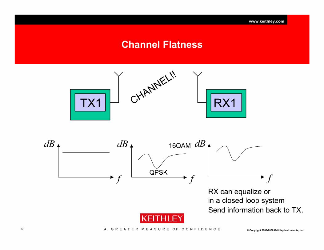
Channel Flatness
TX1 RX1CHANNEL!!
f
dB
f
dB
f
dB
RX can equalize or
in a closed loop system
Send information back to TX.
QPSK
16QAM

A G R E A T E R M E A S U R E O F C O N F I D E N C E
www.keithley.com
© Copyright 2007-2008 Keithley Instruments, Inc.33
OFDM to OFDMA
• OFDM used by WLAN and WiMAX Fixed (802.16d) as a
modulation technique is not multi user – all sub-carriers in a
channel are used to facilitate a single link.
• OFDMA used by WiMAX mobile (802.16e) and LTE (3GPP
Release 8) assigning different number of sub-carriers to
different users.

A G R E A T E R M E A S U R E O F C O N F I D E N C E
www.keithley.com
© Copyright 2007-2008 Keithley Instruments, Inc.34
WiMAX (Mobile) sub-channels Frequency Domain
…………………….
Subchannel0 Subchannel1 ……………. Subchanneln
f

A G R E A T E R M E A S U R E O F C O N F I D E N C E
www.keithley.com
© Copyright 2007-2008 Keithley Instruments, Inc.35
The Physical Channels are Different from the Logical
Channels

A G R E A T E R M E A S U R E O F C O N F I D E N C E
www.keithley.com
© Copyright 2007-2008 Keithley Instruments, Inc.36
k k+1 k+4 k+5 k+6 k+7 k+8 k+9 k+10k+2 k+3
OFDM Symbol Number
Pre-
ambleDL-
MapUL BurstDL Burst
Transition
Gap
Transition
Gap
Sub C
ha
nne
l N
um
ber
0
.
.
.
.
.
.
.
n
Symbol Transmission verses Time
Remember OFDM allows us to transmit
symbols in parallel. An OFDM symbol
period is a group of parallel symbols.

A G R E A T E R M E A S U R E O F C O N F I D E N C E
www.keithley.com
© Copyright 2007-2008 Keithley Instruments, Inc.37
The WiMAX Symbol Map

A G R E A T E R M E A S U R E O F C O N F I D E N C E
www.keithley.com
© Copyright 2007-2008 Keithley Instruments, Inc.38
WiMAX putting it all together
Frame (t)
Down Link (DL) Up Link (UL)
Transition Gap
Pre
amble DL 1DL
x
Su
b C
ha
nn
els
DL
y
OFDM Symbol (t) = (1 / Carrier Spacing ) + Guard Interval
Useful Time (t) = FFT SizeGuard
Interval (t)
OFDM Symbol (t)
FFT Size = 1 / Carrier Spacing
1/41/81/161/32
Guard Interval (t)
1/41/81/161/32
Guard Interval (t)
Symbol Map

A G R E A T E R M E A S U R E O F C O N F I D E N C E
www.keithley.com
© Copyright 2007-2008 Keithley Instruments, Inc.39
Creating a Signal
Frame (t)
Down Link (DL) Up Link (UL)
Transition Gap
Pre
amble DL User 1DL
User x
Su
b C
ha
nne
ls
DL
User y
OFDM Symbol (t) = (1 / Carrier Spacing ) + Guard Interval
Useful Time (t) = FFT SizeGuard
Interval (t)
OFDM Symbol (t)
FFT Size = 1 / Carrier Spacing
1/41/81/161/32
Guard Interval (t)
1/41/81/161/32
Guard Interval (t)

A G R E A T E R M E A S U R E O F C O N F I D E N C E
www.keithley.com
© Copyright 2007-2008 Keithley Instruments, Inc.40
Time Domain Measurement
Preamble User Slot

A G R E A T E R M E A S U R E O F C O N F I D E N C E
www.keithley.com
© Copyright 2007-2008 Keithley Instruments, Inc.41
Frequency Domain Transient Effects
With Transients Gated on Slot

A G R E A T E R M E A S U R E O F C O N F I D E N C E
www.keithley.com
© Copyright 2007-2008 Keithley Instruments, Inc.42
Peak to Average Ratio
for WiMAX and WLAN
GMSK QPSK QAM OFDM
PAR
10-13
4-9
3-4
1

A G R E A T E R M E A S U R E O F C O N F I D E N C E
www.keithley.com
© Copyright 2007-2008 Keithley Instruments, Inc.43
Gain Compression Issues
• Gain compression is illustrated graphically in figure 1.
•The 1dB Gain Compression point is the input power level that causes the actual
amplifier output level to be 1dB less than the extrapolated linear small signal
behavior.
figure 1. 1dB Gain Compression

A G R E A T E R M E A S U R E O F C O N F I D E N C E
www.keithley.com
© Copyright 2007-2008 Keithley Instruments, Inc.44
Random Phase Addition
of Multi-carrier QAM 64 Waveforms
• Since each sub-carrier transmits their symbols in the same channel the instantaneous
signal power due to random phases can add up constructively or they can cancel out.
• This means that the range of signal powers that the RF amplifier has to generate is widely
varying and very dynamic. This is what creates the high peak to average ratio (PAR)
Summed QAM 64 vectorsA. Vector phase summation
B. Vector phase cancellation

A G R E A T E R M E A S U R E O F C O N F I D E N C E
www.keithley.com
© Copyright 2007-2008 Keithley Instruments, Inc.45
Effects of Gain Compression in OFDM Signals
•Waveforms having a large PAR can severely stress an RF amplifier causing it to
distort during peaks.
•The issue for measurement instrumentation is that it is not always easy to tell
whether an amplifier is being stressed into compression because the signals are so
noise like.
802.11A 64QAM signal with 0% compression in zero span 802.11A 64QAM signal with 20% compression in zero span

A G R E A T E R M E A S U R E O F C O N F I D E N C E
www.keithley.com
© Copyright 2007-2008 Keithley Instruments, Inc.46
Effects of Gain Compression in OFDM Signals
• There are obvious degradations to the signal as viewed in the frequency domain
as distortion increases, but it is difficult to derive a quantitive measure that
would provide the designer feedback to optimize the circuit.
802.11A 64QAM signal with 0% compression 802.11A 64QAM signal with 20% compression

A G R E A T E R M E A S U R E O F C O N F I D E N C E
www.keithley.com
© Copyright 2007-2008 Keithley Instruments, Inc.47
Quantifying Gain Compression for OFDM Signals
•The noise like nature of OFDM signals means that in order to extract useful information from the
signal a statistical description of the waveform’s power levels is required.
•For these types of signals a complimentary cumulative distribution function (CCDF) is required.
•CCDF curves can specify completely the power characteristics of the signals that are
transmitted in a communications channel.
Figure 2. CCDF curve of 802.11A
64QAM signal - No Compression.
Notice the Y-axis is in percent and the x-
axis is in dB relative to the average
power.
This signal spends almost 1% of it’s time
at 8dB above the average power.

A G R E A T E R M E A S U R E O F C O N F I D E N C E
www.keithley.com
© Copyright 2007-2008 Keithley Instruments, Inc.48
Quantifying Gain Compression for OFDM Signals
Figure 3. CCDF curve of 802.11A
64QAM signal – with 10% compression.
The compressed signal is noticeable on
the CCDF curve but there can be no way
to make a measurement of compression
levels.
This signal spends almost 1% of it’s time
at 7.25dB above the average power.
• The addition of Gain Compression in this amplifier has affected the CCDF curve but not
in any way that you could reliably indicate the level of gain compression.

A G R E A T E R M E A S U R E O F C O N F I D E N C E
www.keithley.com
© Copyright 2007-2008 Keithley Instruments, Inc.49
Symbol to WaveformOFDM – Parallel Symbol Transmissions
f1
f2
f3
f4
…fn
OFDM Symbol Period
Multiple carriers will transmit multiple symbols in parallel.
Carriers may have different modulations – BPSK, QPSK… 64QAM.
I waveform
Q waveform

A G R E A T E R M E A S U R E O F C O N F I D E N C E
www.keithley.com
© Copyright 2007-2008 Keithley Instruments, Inc.50
Quantifying Gain Compression for OFDM Signals
• Compare the measured time-domain signal with
a reference signal and plot the difference as a
function of input magnitude.
• The reference signal is an ideal time-domain
waveform, constructed from the demodulated
symbol targets using an IFFT.
• Time domain errors are measured as a function
of input magnitude.
• The linear gain error equates to the gain
compression.
• Linear gain error is plotted relative to full scale.
This gives % magnitude error as a function of
input magnitude.
Measured Magnitude – Reference Magnitude
Full Scale Magnitude
Reference Signal
Measured time-
domain waveform
time
Amplitude Error = Gain Error

A G R E A T E R M E A S U R E O F C O N F I D E N C E
www.keithley.com
© Copyright 2007-2008 Keithley Instruments, Inc.51
Quantifying Gain Compression for OFDM Signals
• Keithley has developed a measurement technique that can easily and reliably discern
the level of gain compression in RF amplifier DUT’s employing OFDM signaling.
Figure 4. Keithley Gain Compression
Measurement algorithm – No deliberate
compression.
The Y-axis scale shows the level
of amplitude error in percent %.
The X-axis scale shows the full scale
input power range in percent %
Axis are Error in observed power level vs expected power level.
A G R E A T E R M E A S U R E O F C O N F I D E N C E
www.keithley.com
© Copyright 2007-2008 Keithley Instruments, Inc.52
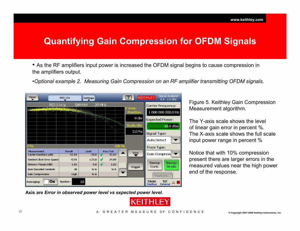
Quantifying Gain Compression for OFDM Signals
• As the RF amplifiers input power is increased the OFDM signal begins to cause compression in
the amplifiers output.
•Optional example 2. Measuring Gain Compression on an RF amplifier transmitting OFDM signals.
Figure 5. Keithley Gain Compression
Measurement algorithm.
The Y-axis scale shows the level
of linear gain error in percent %.
The X-axis scale shows the full scale
input power range in percent %
Notice that with 10% compression
present there are larger errors in the
measured values near the high power
end of the response.
Axis are Error in observed power level vs expected power level.

A G R E A T E R M E A S U R E O F C O N F I D E N C E
www.keithley.com
© Copyright 2007-2008 Keithley Instruments, Inc.53
WiMAX and LTE
60kHz (4x15khz)15kHz10.94KHzSub-carrier
spacing
TDD/FDDTDD/FDDTDD/FDDDuplex
SISOUp to 4Up to 4MIMO
QPSK, 16QAM,
64QAM
SC-FDMA
Up to 20MHz
LTE (Up Link)
QPSK, 16QAM,
64QAM
OFDMA
Up to 20MHz
LTE (Down Link)
OFDMAAccess scheme
QPSK, 16QAM,
64QAM
Modulation
Up to 20MHzBandwidth
WiMAX (802.16e)

A G R E A T E R M E A S U R E O F C O N F I D E N C E
www.keithley.com
© Copyright 2007-2008 Keithley Instruments, Inc.54
WiMAX TDD Frame Structure
Frame (t)
Down Link (DL) Up Link (UL)
Transition Gap
Pre
amble DL 1DL
x
Sub C
hannels
DL
y
OFDM Symbol (t) = (1 / Carrier Spacing ) + Guard Interval
Useful Time (t) = FFT SizeGuard
Interval (t)
OFDM Symbol (t)
FFT Size = 1 / Carrier Spacing
1/41/81/161/32
Guard Interval (t)
1/41/81/161/32
Guard Interval (t)
WiMAX
Uses a
preamble
A G R E A T E R M E A S U R E O F C O N F I D E N C E
www.keithley.com
© Copyright 2007-2008 Keithley Instruments, Inc.55
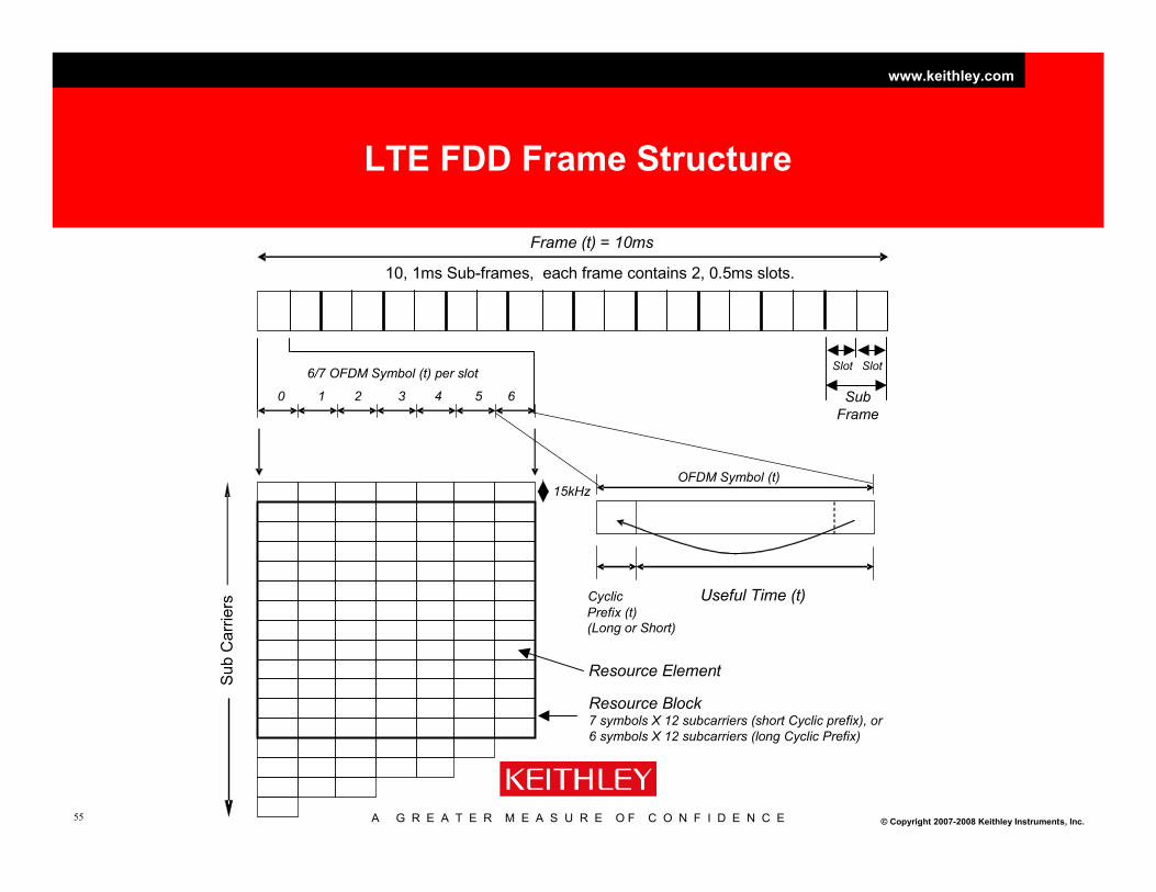
LTE FDD Frame Structure
Frame (t) = 10ms
10, 1ms Sub-frames, each frame contains 2, 0.5ms slots.
6/7 OFDM Symbol (t) per slot
Useful Time (t)Cyclic
Prefix (t)
(Long or Short)
OFDM Symbol (t)
Slot
Sub
Frame
Slot
0 1 2 3 4 5 6
Sub C
arr
iers
Resource Element
Resource Block7 symbols X 12 subcarriers (short Cyclic prefix), or
6 symbols X 12 subcarriers (long Cyclic Prefix)
15kHz

A G R E A T E R M E A S U R E O F C O N F I D E N C E
www.keithley.com
© Copyright 2007-2008 Keithley Instruments, Inc.56
LTE, is not packet based
Sub C
arr
iers
6/7 OFDM Symbol (t) per slot
0 1 2 3 4 5 6
LTE is not a packet-oriented network, therefore
does not employ preamble for carrier offset,
channel estimation and timing synchronization. It
uses reference signals transmitted during the
first and fifth OFDM symbols of each slot when
the short Cyclic prefix is used and during the first
and fourth OFDM symbols when the long Cyclic
Prefix is used.
15kHz

A G R E A T E R M E A S U R E O F C O N F I D E N C E
www.keithley.com
© Copyright 2007-2008 Keithley Instruments, Inc.57
LTE Up Link SC-FDMA Single Carrier – Frequency Domain Multiple Access
Sub C
arr
iers
6/7 OFDM Symbol (t) per slot
0 1 2 3 4 5 6
Sub C
arr
iers
6/7 OFDM Symbol (t) per slot
0 1 2 3 4 5 6
In the baseband section SC-FDMA combines four subcarriers worth of symbols, then
transmit them in a single symbol period using a carrier has four times the bandwidth.
60kHz
15kHz
OFDMA SC-FDMA

A G R E A T E R M E A S U R E O F C O N F I D E N C E
www.keithley.com
© Copyright 2007-2008 Keithley Instruments, Inc.58
WiMAX Up Link vs. LTE Up Link
• Proponents of LTE state that SC-FDMA with a lower peak to
average ratio can use a lower cost power amplifier, thus
saving in cost and battery life.
• Proponents of WiMAX state that the increased baseband
processing requirements for SC-FDMA requires a more
expensive FPGA or ASIC that uses more power thus
reducing battery life.

A G R E A T E R M E A S U R E O F C O N F I D E N C E
www.keithley.com
© Copyright 2007-2008 Keithley Instruments, Inc.59
Summary
• Advantages
– Improved spectral efficiency
– Good multipath performance
– Resilient to interference
– Complementary to MIMO transmission. (Part 2)
• Disadvantages
– Increased baseband processing requirements.
– High peak to average ratio.

A G R E A T E R M E A S U R E O F C O N F I D E N C E
www.keithley.com
© Copyright 2007-2008 Keithley Instruments, Inc.60
Agenda
• The evolution of communications and an introduction to the test tools
• Part One – OFDM and SISO radio configurations– The case for OFDM
– OFDM Signal Structure, generic and WLAN.
– Measurements
– OFDM and OFDMA
– Peak to average ratio considerations
– WiMAX and LTE
• Part Two – OFDM and MIMO radio configurations– MIMO – Multiple Input Multiple Output Radio Topology
– How it works.
– Measurements
– Channel Considerations
– Smart Antenna Systems and Beam Forming Considerations
• Technology Overview and Test Equipment Summary

A G R E A T E R M E A S U R E O F C O N F I D E N C E
www.keithley.com
© Copyright 2007-2008 Keithley Instruments, Inc.61
OFDM/A to MIMO
• MIMO based systems use multiple transmitters and
receivers that are modulated with OFDM/A.
• WLAN (802.11n), WiMAX (802.16e) and LTE (3GPP Rel 8) all
have MIMO configurations.
A G R E A T E R M E A S U R E O F C O N F I D E N C E
www.keithley.com
© Copyright 2007-2008 Keithley Instruments, Inc.62
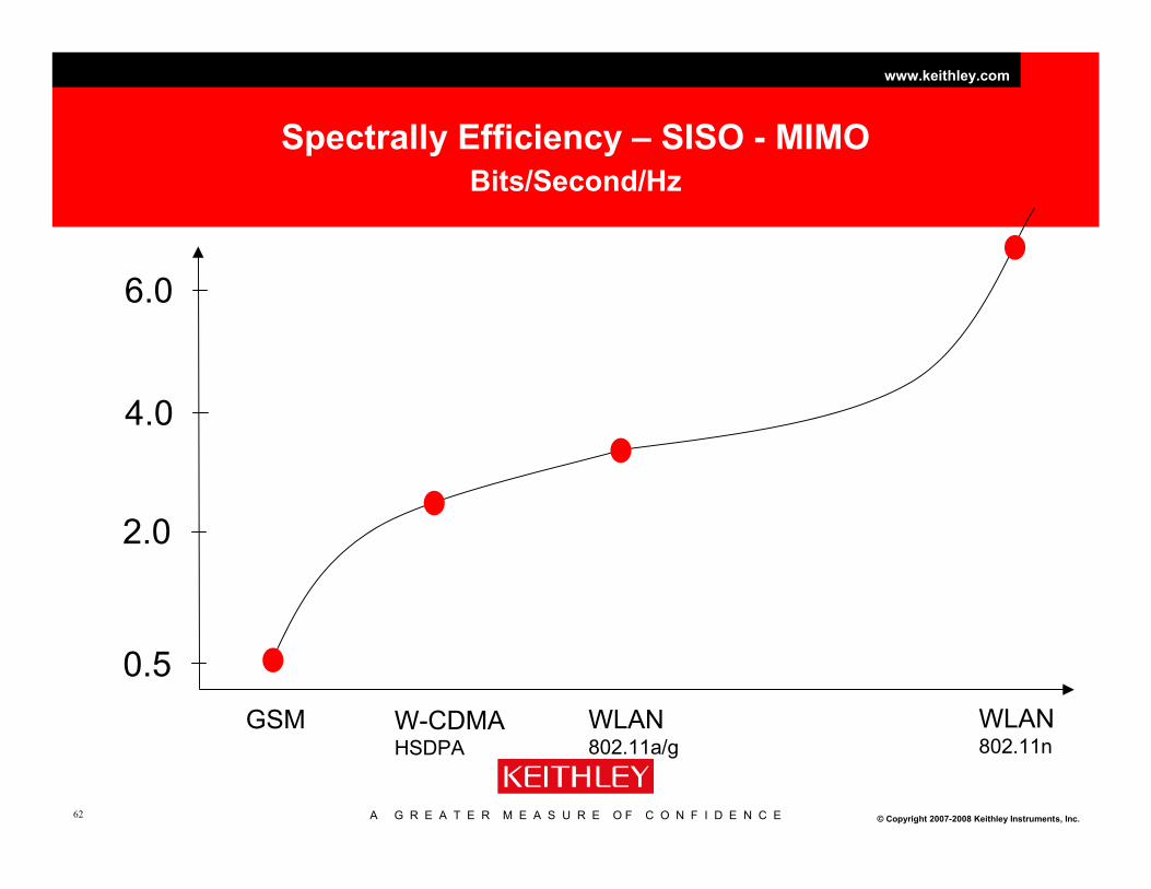
Spectrally Efficiency – SISO - MIMO
Bits/Second/Hz
GSM W-CDMAHSDPA
WLAN802.11a/g
0.5
2.0
4.0
6.0
WLAN802.11n

A G R E A T E R M E A S U R E O F C O N F I D E N C E
www.keithley.com
© Copyright 2007-2008 Keithley Instruments, Inc.63
MIMO Configurations
Spatial Diversity, Spatial Multiplexing and Beam Forming
• Multiple replicas of the radio signal from different directions in
space give rise to spatial diversity, which increases the reliability
of the fading radio link.
• MIMO channels can support parallel data streams by
transmitting and receiving on orthogonal spatial filters ("spatial
multiplexing").
• Beamforming, the transmit and receive antenna patterns can be
focused into a specific angular direction by the appropriate
choice of complex baseband antenna weights. The more
correlated the antenna signals, the better for beamforming.
A G R E A T E R M E A S U R E O F C O N F I D E N C E
www.keithley.com
© Copyright 2007-2008 Keithley Instruments, Inc.64
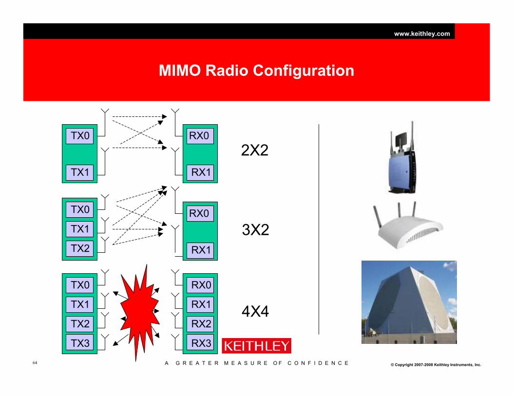
MIMO Radio Configuration
TX0
TX1
RX0
RX1
TX0
TX1
TX2
RX0
RX1
TX0
TX1
TX2
TX3
RX0
RX1
RX2
RX3
2X2
3X2
4X4

A G R E A T E R M E A S U R E O F C O N F I D E N C E
www.keithley.com
© Copyright 2007-2008 Keithley Instruments, Inc.65
40MHz 40MHz 40MHz
Why is MIMO different from standard OFDM?
40MHz
~ 4 x Information or 4 copies of information,
but with 4 x the BW
40MHz
~ 3.5 x Information, but with 1 x the BW

A G R E A T E R M E A S U R E O F C O N F I D E N C E
www.keithley.com
© Copyright 2007-2008 Keithley Instruments, Inc.66
Generate a 2x2 MIMO signal.WiMAX Matrix A Space Time Coding

A G R E A T E R M E A S U R E O F C O N F I D E N C E
www.keithley.com
© Copyright 2007-2008 Keithley Instruments, Inc.67
Solving for original stream symbols
MIMO requires lots of paths!
If you have two unknown
transmitted signals and two
measurements at the
receivers. If the two
measurements are
sufficiently independent, you
can solve for the transmitted
symbols!

A G R E A T E R M E A S U R E O F C O N F I D E N C E
www.keithley.com
© Copyright 2007-2008 Keithley Instruments, Inc.68
MathematicallyModel the Channel
y = Hx + n
y = Receive Vector
x = Transmit Vector
H = Channel Matrix
n = Noise Vector
TX1
TX2
RX1
RX2
Channel
h11 = a+jb
h22
h21h12
h11 h12h21 h22
H =
n (noise)

A G R E A T E R M E A S U R E O F C O N F I D E N C E
www.keithley.com
© Copyright 2007-2008 Keithley Instruments, Inc.69
Correct for channel effects
TX0
TX1
RX0
RX1
Channel
h11 = a+jb
h22
h21h12
h11 h12h21 h22
TX0TX1
=RX0RX1
- n
RX = H * TX + n
Header
Data Data
Note this has the disadvantage of possible noise enhancement if |H| is small.

A G R E A T E R M E A S U R E O F C O N F I D E N C E
www.keithley.com
© Copyright 2007-2008 Keithley Instruments, Inc.70
A Different Channel Model
Three matrices can represent the channel
U VH
.
.
H=UDVH
D. Scaling matrix,
or singular values

A G R E A T E R M E A S U R E O F C O N F I D E N C E
www.keithley.com
© Copyright 2007-2008 Keithley Instruments, Inc.71
The Details
•We could also express H as:
•We represent the U and V matrices as column vectors of their singular
values for convenience.
•The factor D, is composed of the singular values of H
[ ]
=••=
−−
−
H
N
H
H
M
N
H uuu
1
1
0
1
0
0
110
000
000
000
V
V
V
VDUHKKKKK
K
σ
σ
σ

A G R E A T E R M E A S U R E O F C O N F I D E N C E
www.keithley.com
© Copyright 2007-2008 Keithley Instruments, Inc.72
A more Complete Channel Model
V
RX0
RX1
Channel
h11 = a+jb
h22
h21h12
H=U.D.VH
TX0
TX1
UH
n (noise) RX = U.D.VH.TX + n
����”Do the math” and
����RX=D.TX+UH.n
D elements are singular
values of H.
Also, |U| is unitary, so
there is no
noise enhancement.

A G R E A T E R M E A S U R E O F C O N F I D E N C E
www.keithley.com
© Copyright 2007-2008 Keithley Instruments, Inc.73
WLAN ExampleNumber of Stream and Modulation type is determined by the MCS
Selecting Modulation Coding
Schemes (MCS)
• The table at right contains the
specification of some of the
802.11n defined MCS
• This information is
automatically encoded in the
packet header of the 802.11n
waveform, and automatically
decoded by the WLAN
analyzer program
540260245/664-
QAM
31
32415624¾16-
QAM
28
324156222/364-
QAM
21
24311712¾64-
QAM
14
271312½BPSK8
13565115/664-
QAM
7
271311½QPSK1
13.56.511½BPSK0
PHY rate
40 MHz
PHY rate
20 MHz
FEC
coders
Spatial
Streams
Code
rate
Modulati
on
MCS
Index
For example a 2x2 BPSK can be analyzed by setting the MCS index to 8

A G R E A T E R M E A S U R E O F C O N F I D E N C E
www.keithley.com
© Copyright 2007-2008 Keithley Instruments, Inc.74
2x2 MIMO Configuration
Spatial Stream 1 Spatial Stream 2
Masters Slaves
Analyzers �
Generators �
VSA MIMO Sync Unit �
VSG MIMO Sync Unit �

A G R E A T E R M E A S U R E O F C O N F I D E N C E
www.keithley.com
© Copyright 2007-2008 Keithley Instruments, Inc.75
Generate a Signal

A G R E A T E R M E A S U R E O F C O N F I D E N C E
www.keithley.com
© Copyright 2007-2008 Keithley Instruments, Inc.76
Test conditions require different channel conditions
TX0
TX1
RX0
RX1
Channel
h11 = a+jb
h22
h21h12
Channel isolation < 40dB
Channel Flatness
In this example we use an RF
cable to connect the TX to the RX.
We see four plots TX0-RX0, TX1-RX1,
TX0-RX1 and TX1-RX0
Models Channel Behavior

A G R E A T E R M E A S U R E O F C O N F I D E N C E
www.keithley.com
© Copyright 2007-2008 Keithley Instruments, Inc.77
Examine different channel conditions
Magnitude only increase in cross components

A G R E A T E R M E A S U R E O F C O N F I D E N C E
www.keithley.com
© Copyright 2007-2008 Keithley Instruments, Inc.78
Add delay to the equation
40 Sample Delay
Deep fade
In channel now
apparent.

A G R E A T E R M E A S U R E O F C O N F I D E N C E
www.keithley.com
© Copyright 2007-2008 Keithley Instruments, Inc.79
Key Measurements
2: Channel Metrics - Singular Value Decomposition
SVD
Three matrices can represent the channel
U VH
.
.
H=UDVH
D. Scaling matrix,
or singular values

A G R E A T E R M E A S U R E O F C O N F I D E N C E
www.keithley.com
© Copyright 2007-2008 Keithley Instruments, Inc.80
Key Measurements
2: Channel Metrics - Matrix Condition
The ratio of the highest singular value to
the lowest is called the matrix condition.
If the received path was received with
equal signal to noise, then the matrix
condition would be unity. If the signal to
noise ratio is very low on one of the
paths, then the matrix condition would
be high.
Scaling matrix,
or singular values
.
.

A G R E A T E R M E A S U R E O F C O N F I D E N C E
www.keithley.com
© Copyright 2007-2008 Keithley Instruments, Inc.81
Matrix Condition
Note: Deep
Fade
Causes Low
Signal to
Noise,
Creating a
high matrix
condition
number.

A G R E A T E R M E A S U R E O F C O N F I D E N C E
www.keithley.com
© Copyright 2007-2008 Keithley Instruments, Inc.82
Channel Models

A G R E A T E R M E A S U R E O F C O N F I D E N C E
www.keithley.com
© Copyright 2007-2008 Keithley Instruments, Inc.83
802.11n Analysis Display
2x2 MIMO Example with Channel Model E

A G R E A T E R M E A S U R E O F C O N F I D E N C E
www.keithley.com
© Copyright 2007-2008 Keithley Instruments, Inc.84
Understanding and Modeling the Channel
Sound the channel
h(t,τ)τ τt
f
Channel Response
Frequency ResponseTime Domain Impulse
Distorted Time Domain Impulse
Channel

A G R E A T E R M E A S U R E O F C O N F I D E N C E
www.keithley.com
© Copyright 2007-2008 Keithley Instruments, Inc.85
Model The Channel –
Multi-path Represented by a Power Delay Profile
TX0
TX1
RX0
RX1
Because of multiple path reflections,
the channel impulse response of a
wireless channel looks likes a series
of pulses. In practice the number of
pulses that can be distinguished is
very large, and depends on the time
resolution of the communication or
measurement system.
dB
t
dB
t
ttx=0
trx=ttx+delay1
trx=ttx+delayn

A G R E A T E R M E A S U R E O F C O N F I D E N C E
www.keithley.com
© Copyright 2007-2008 Keithley Instruments, Inc.86
Static Channel Model Only
• Sounding the channel with an impulse models the channel
at single point in time does not account for mobility or
environmental changes.
• A real time emulator such as the Azimuth Emulator would
be used for this.
Example of a channel emulator:
Azimuth Systems ACE 400WB
4x4 bidirectional unitwww.azimuthsystems.com

A G R E A T E R M E A S U R E O F C O N F I D E N C E
www.keithley.com
© Copyright 2007-2008 Keithley Instruments, Inc.87
Smart Antenna Systems and Beam Forming
A G R E A T E R M E A S U R E O F C O N F I D E N C E
www.keithley.com
© Copyright 2007-2008 Keithley Instruments, Inc.88
Antenna Systems
• Diversity – most commonly used antenna system
• Sectorized – used by base stations
• Smart – Form a radiated RF beam, beam forming.
– Fixed
– Adaptive

A G R E A T E R M E A S U R E O F C O N F I D E N C E
www.keithley.com
© Copyright 2007-2008 Keithley Instruments, Inc.89
Diversity Systems (Time)
– Switched/Selection diversity:
• The system continually switches between antennas so as always to use the element with the largest output.
• No gain increase since only one antenna is used at a time.
– Diversity combining:
• This approach constructively sums the signals by correcting the phase error in two multi path signals effectively combining the power of both signals to produce gain.
Single Data Channel
11
Q
I
Q
I10 01 10 11
Q
I
Q
I

A G R E A T E R M E A S U R E O F C O N F I D E N C E
www.keithley.com
© Copyright 2007-2008 Keithley Instruments, Inc.90
Diversity System (Space)
MIMO based.
A single data stream is replicated and transmitted over multiple antennas.
The redundant data streams are each encoded using a mathematical
algorithm known as Space Time Block Codes.
Each transmitted signal is orthogonal to the rest reducing self-interference
and improving the capability of the receiver to distinguish between the
multiple signals.
With the multiple transmissions of the coded data stream, there is increased
opportunity for the receiver to identify a strong signal that is less adversely
affected by the physical path.
The receiver additionally can use a diversity combining technique to combine
the multiple signals for more robust reception.

A G R E A T E R M E A S U R E O F C O N F I D E N C E
www.keithley.com
© Copyright 2007-2008 Keithley Instruments, Inc.91
Spatial Diversity
WiMAX Matrix A STC vs Matrix B SMX
TX0
TX1
RX0
RX1
11010101001010101
TX0
TX1
RX0
RX1
110001100110 Matrix A – Transmit Inverse Symbols
11 01
Thro
ug
hp
ut
Covera
ge
Matrix B – Transmit Parallel Symbols

A G R E A T E R M E A S U R E O F C O N F I D E N C E
www.keithley.com
© Copyright 2007-2008 Keithley Instruments, Inc.92
Sectorized antenna systems
Radiation Pattern
Side View Top View

A G R E A T E R M E A S U R E O F C O N F I D E N C E
www.keithley.com
© Copyright 2007-2008 Keithley Instruments, Inc.93
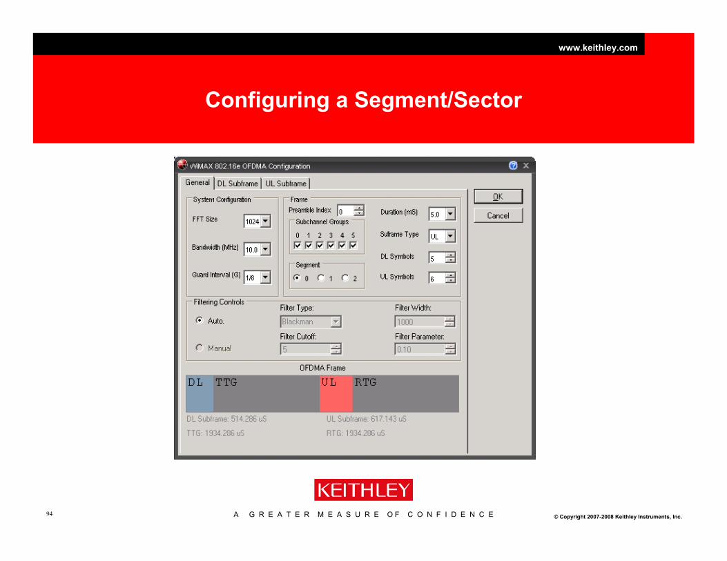
WiMAX and sectorized transmission.
• The Base Station may
have multiple BS MACs.
• Each BS MAC may have a
portion of the subchannel
groups referred to as a
segment.
• The functionality
supports sectorized
transmission.
A G R E A T E R M E A S U R E O F C O N F I D E N C E
www.keithley.com
© Copyright 2007-2008 Keithley Instruments, Inc.94
Configuring a Segment/Sector

A G R E A T E R M E A S U R E O F C O N F I D E N C E
www.keithley.com
© Copyright 2007-2008 Keithley Instruments, Inc.95
Smart Antenna Technology
• How can an antenna be made more intelligent?
– Instead of having one transmitter you require multiple, the
more the better!
– The antenna becomes an antenna system that can be
designed to shift signals before transmission at each of the
successive elements so that the antenna has a composite
effect.
– When transmitting, a beam former controls the phase and
relative amplitude of the signal at each transmitter, in order to
create a pattern of constructive and destructive interference in
the wave front. When receiving, information from different
sensors is combined in such a way that the expected pattern
of radiation is preferentially observed.
TX0
TX1
TX2
TX3

A G R E A T E R M E A S U R E O F C O N F I D E N C E
www.keithley.com
© Copyright 2007-2008 Keithley Instruments, Inc.96
Beam Forming Benefits
TX0
TX1
TX2
TX3
By controlling the directionality and shape of the radiated
pattern increased range, capacity and the throughput of the
transmission is achieved.

A G R E A T E R M E A S U R E O F C O N F I D E N C E
www.keithley.com
© Copyright 2007-2008 Keithley Instruments, Inc.97
Antenna Radiation Pattern

A G R E A T E R M E A S U R E O F C O N F I D E N C E
www.keithley.com
© Copyright 2007-2008 Keithley Instruments, Inc.98
Log Plot of Radiation Pattern
Azimuth (“E” plane)
Main Lobe
Side Lobe
(20dB down)
dB from
Maximum gain
Degrees from
Main Lobe axis

A G R E A T E R M E A S U R E O F C O N F I D E N C E
www.keithley.com
© Copyright 2007-2008 Keithley Instruments, Inc.99
Fixed Beam Forming
0
1
2
3
7
6
5
4
Main Lobe

A G R E A T E R M E A S U R E O F C O N F I D E N C E
www.keithley.com
© Copyright 2007-2008 Keithley Instruments, Inc.10
0
The Adaptive Beam Forming Process
LTE Example - Closed Loop
TX0
TX1
TX2
TX3
Sound Channel
Feedback Channel Characteristics
Direct Beam
Look up table approach

A G R E A T E R M E A S U R E O F C O N F I D E N C E
www.keithley.com
© Copyright 2007-2008 Keithley Instruments, Inc.10
1
Antenna Correlation
High and Low
High - The distance between antennas is small (less than one
wavelength).
•Assume the same fade for each antenna (channel).
•The beam can be steered by phase shifts alone
•The beam tends to be wide
Low – The distance between antennas large (typically several
wavelengths), or change polarization H vs. E.
•Assume different fading characteristics for each antenna
(channel).
•Beam must be steered by phase shifts and magnitude changes
via the beam steering vector.

A G R E A T E R M E A S U R E O F C O N F I D E N C E
www.keithley.com
© Copyright 2007-2008 Keithley Instruments, Inc.10
2
Antenna Correlation
High and Low
TX0 TX1
RX0 RX1
Distance
Tx to Rx
Rx Spacing
Tx Spacing

A G R E A T E R M E A S U R E O F C O N F I D E N C E
www.keithley.com
© Copyright 2007-2008 Keithley Instruments, Inc.10
3
Single layer Beam Forming
•To maximize the signal at the receiver:
•Select a beam forming vector V such that
vi = hi* / sqrt(Σk=1
Nt |hk|2 )
•This normalizes the signal to the complex conjugate of the channel so that
total transmit power is unchanged.
•Observations:
•This technique phase rotates the transmit signals so received signals are
time aligned.
•In general, more power is allocated to antennas with good channel
conditions. This maximizes capacity.
•Overall transmit power is constant.

A G R E A T E R M E A S U R E O F C O N F I D E N C E
www.keithley.com
© Copyright 2007-2008 Keithley Instruments, Inc.10
4
Single layer Beam Forming
•High correlation vs. Low Correlation beam forming observations:
•More knowledge of channel is needed for low correlation beam forming.
•The beam forming vector must take the channel into account.
•For FDD (Frequency Division Duplex), only the receiver knows the
channel, so it must feedback channel information to the transmitter.
•For TDD (Time Division Duplex) the up and down links share frequencies
so the channel is known without feedback.
•The above assumes channel gain is constant vs. frequency. If it’s not
then no single set of B coefficients are possible.
•This can be resolved by using OFDM precoding weight based on
each sub-carrier characteristic.
A G R E A T E R M E A S U R E O F C O N F I D E N C E
www.keithley.com
© Copyright 2007-2008 Keithley Instruments, Inc.10
5
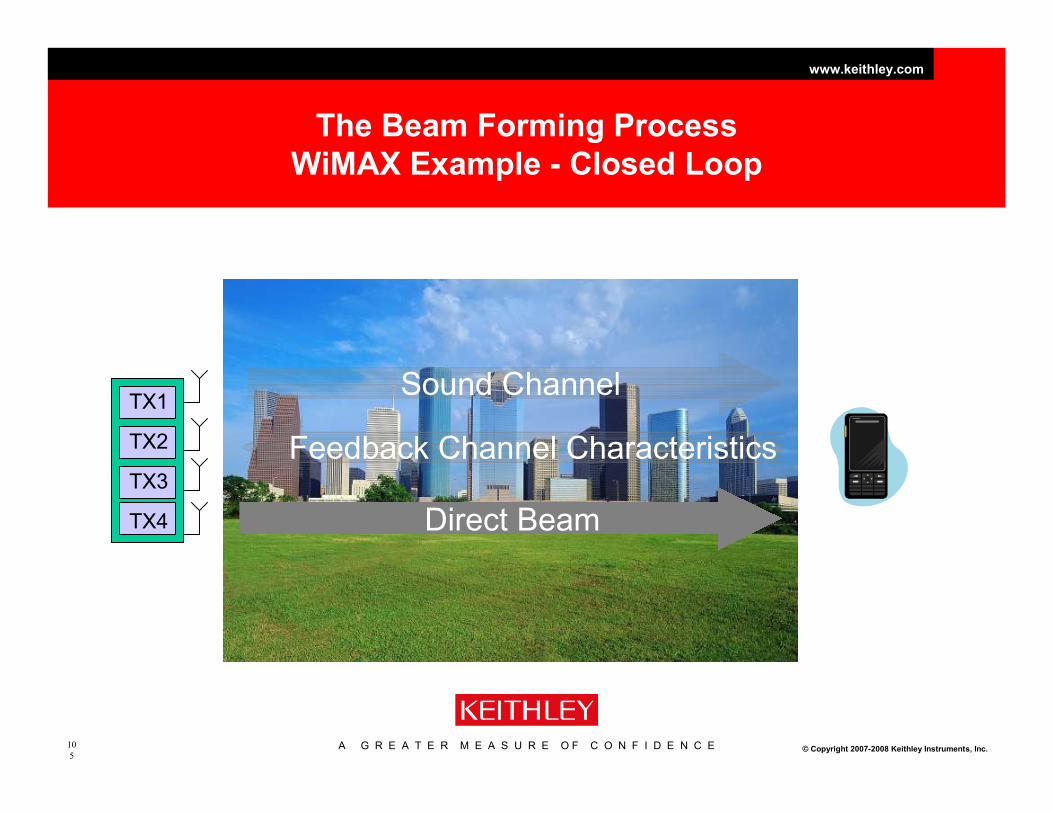
The Beam Forming Process
WiMAX Example - Closed Loop
TX1
TX2
TX3
TX4
Sound Channel
Feedback Channel Characteristics
Direct Beam

A G R E A T E R M E A S U R E O F C O N F I D E N C E
www.keithley.com
© Copyright 2007-2008 Keithley Instruments, Inc.10
6
Creating a Signal

A G R E A T E R M E A S U R E O F C O N F I D E N C E
www.keithley.com
© Copyright 2007-2008 Keithley Instruments, Inc.10
7
VSA and VSG Subsystem Configuration Groups…
…that are Synchronized Analyzers and Generators1
2895 MIMO Sync
2820
VSA
2820
VSA
2895 MIMO Sync
2920
VSG
2920
VSG
4x4 MIMO system(or 2x2, 3x3, etc.)
8x8 MIMO system
2820
VSA
2820
VSA
1. Each VSA and VSG subsystem group is synchronized and
cannot be separated. The VSA and VSG subsystems are
separate and asynchronous from each other.
2920
VSG
2920
VSG
VSA subsystem
VSG subsystem
2895 MIMO Sync
2820
VSA
2820
VSA
2820
VSA
2820
VSA
2895 MIMO Sync
2820
VSA
2820
VSA
2820
VSA
2820
VSA
2895 MIMO Sync
2895 MIMO Sync
2920
VSG
2920
VSG
2920
VSG
2920
VSG
2895 MIMO Sync
2920
VSG
2920
VSG
2920
VSG
2920
VSG
2895 MIMO Sync
synchronized
synchronized
not
synchronized

A G R E A T E R M E A S U R E O F C O N F I D E N C E
www.keithley.com
© Copyright 2007-2008 Keithley Instruments, Inc.10
8
Scalable Solutions
SISO 2x2 – 4x4
MIMO
8x8
MIMO
GSM, W-CDMA,
WLAN, WiMAX
WLAN, LTE, WiMAX Advanced Antenna
Research

A G R E A T E R M E A S U R E O F C O N F I D E N C E
www.keithley.com
© Copyright 2007-2008 Keithley Instruments, Inc.10
9
Beam Forming Summary
Coverage/Distance
Adaptive
Switched
Conventional
High Interference
Environments

A G R E A T E R M E A S U R E O F C O N F I D E N C E
www.keithley.com
© Copyright 2007-2008 Keithley Instruments, Inc.11
0
MIMO Conclusion
• Allows for better throughput and coverage
– STC, Space Time Coding
– SMX, Spatial Multiplexing
– Beam forming
• Requires knowledge of channel
• Requires higher levels of baseband processing

A G R E A T E R M E A S U R E O F C O N F I D E N C E
www.keithley.com
© Copyright 2007-2008 Keithley Instruments, Inc.11
1
Typical Test Setup 2x2
TX
RX

A G R E A T E R M E A S U R E O F C O N F I D E N C E
www.keithley.com
© Copyright 2007-2008 Keithley Instruments, Inc.11
2
Throughput, Flexibility, and Ease of Use
Delivered in new wireless connectivity test capabilities
2800 VSA and 2900 VSG
SISO
GSM
CDMA
WLAN
WiMAX
2800 VSA, 2900 VSG + 2895
MIMO
WLAN
WiMAX
LTE

A G R E A T E R M E A S U R E O F C O N F I D E N C E
www.keithley.com
© Copyright 2007-2008 Keithley Instruments, Inc.11
3
Technology Evolution
SISO 2x24x4
8x8
WiFi WiMax WiMax Wave 22G 3G 4G WiFi (n) Beam Forming Phased Array

A G R E A T E R M E A S U R E O F C O N F I D E N C E
www.keithley.com
© Copyright 2004 Keithley Instruments, Inc.11
4
OFDM/MIMO Master Class
Understanding the physical layer principles of
WLAN, WiMAX and LTE
www.keithley.com

A G R E A T E R M E A S U R E O F C O N F I D E N C E
www.keithley.com
© Copyright 2007-2008 Keithley Instruments, Inc.11
5
Back Up Slides

A G R E A T E R M E A S U R E O F C O N F I D E N C E
www.keithley.com
© Copyright 2007-2008 Keithley Instruments, Inc.11
6
Time alignment LTE
2x2 S
ub C
arr
iers
6/7 OFDM Symbol (t) per slot
0 1 2 3 4 5 6
15kHz
Sub C
arr
iers
6/7 OFDM Symbol (t) per slot
0 1 2 3 4 5 6
15kHz

A G R E A T E R M E A S U R E O F C O N F I D E N C E
www.keithley.com
© Copyright 2007-2008 Keithley Instruments, Inc.11
7
A more Complete Channel Model
- leading to a more general solution
Beam
Form
B
RX1
RX2
Channel
h11 = a+jb
h22
h21h12
TX1
TX2
Beam form
B
Combining
W
n (noise)
•The prior diagram suggests we
should modify both the transmit
and receive ends to maximize
signal
•As shown with the diagram on
the left, this is done with a beam
forming matrix, B on the
transmit side and a combining
matrix W, on the receiver.
•Note:
•If we only add W, we get
noise enhancement.
•If we only add B, the
transmit power can be very
high.
Combining vector
W

A G R E A T E R M E A S U R E O F C O N F I D E N C E
www.keithley.com
© Copyright 2007-2008 Keithley Instruments, Inc.11
8
A bit more detail on “Do the math”
•Since we defined H=U.D.VH Lets talk a bit more about that factorization.
•We define UMxM and VNxN to be square, unitary matrices
•In other words: UH.U = VH.V = I. Where I is the identity matrix.
•This also means, UH = U-1 and VH = V-1
•D is the singular values matrix of size MxN whose elements appear
in increasing order.
•VH denotes Hermitian (transpose complex conjugate) ex;
•The result, if H is complex, there is always a singular value
decomposition with positive singular values.
1j2
i23
+
−=
=
H
j,ii,j aa

A G R E A T E R M E A S U R E O F C O N F I D E N C E
www.keithley.com
© Copyright 2007-2008 Keithley Instruments, Inc.11
9
A bit more detail on “Do the math”
•Recall the decoded signal RX is what we want.
•Since we also defined H=UDVH we can rewrite the decoded signal
equation as:
•RX = UH(H.V.Tx+n) = UH(U.D.VH)V.Tx+UH.n
•Recall, UH.U = VH.V = I. I is the identity matrix. So now,
•RX = D.TX + UH.n
•Result: no noise enhancement |UH|=1 and since D is diagonal,
decoded signal is decoupled. In other words, we have orthogonality.