Technology Analysis and MATLAB Simulation …...MIMO and OFDM are used together, that is, MIMO-OFDM...
5
Technology Analysis and MATLAB Simulation based on MIMO Song Xiuping Chongqing College of Electronic Engineering, Chongqing, China [email protected] Keywords: Mimo; Channel Capacity; Matlab; Space Time Coding Abstract: MIMO technology can greatly increase system capacity, improve system bandwidth utilization and improve system performance without increasing system bandwidth and transmission power, thus becoming the key technology of a new generation of high data rate, multi-data type wireless communication systems. The MIMO system is studied in this paper, mainly focusing on the channel capacity analysis of MIMO system. First, starting from the concept of MIMO, the current wireless communication technology is introduced. Then, the basic principle of MIMO technology, space-time coding technology and the model and capacity of MIMO system are introduced. Finally, the capacity of MIMO system with the same transmitting antenna, different receiving antennas and different SNR is simulated by MATLAB software, and the simulation results are analyzed. 1. Introduction MIMO is widely used in the fourth generation mobile communication technology standards, such as IEEE 802.16e (Wimax), Long Term Evolution (LTE). In the new generation of wireless local area network (WLAN) standards, it is usually used for 802.11n, but it can also be used for other 802.11 technologies. MIMO is sometimes called spatial diversity because it uses multiple spatial channels to transmit and receive data. MIMO can only be deployed if the site (mobile device) or access point (AP) supports MIMO. MIMO technology can significantly overcome channel fading and reduce bit error rate. The application of this technology makes space a resource that can be used to improve performance and increase the coverage of wireless systems. Usually, multipaths cause fading and are considered harmful factors. However, the results show that for MIMO systems, multipath can be used as a favorable factor. MIMO system uses multi-antenna (or array antenna) and multi-channel at both transmitter and receiver. MIMO multi-input and multi-output is for multi-path wireless channel. The transmission information stream s(k) is coded by space-time to form N information sub-streams ci(k), I=1,... N. The N sub-streams are transmitted by N antennas and received by M receiving antennas via space channel. Multi-antenna receivers use advanced space-time coding processing to separate and decode these data sub-streams, so as to achieve the best processing. In this paper, the principle and application scenario of MIMO are studied. At the same time, the relationship between channel capacity and transmitting antenna and receiving antenna is analyzed by using MATLAB. 2. MIMO System Model It can be seen that the MIMO model has a space-time encoder and multiple antennas. The system model is consistent with the above MIMO system theory. Why T n > R n ,In general, mobile terminals always support fewer antennas than base stations. The receiving vector is: y Hx n = + That is to say, the received signal is channel fading coefficient X transmitting signal + receiver noise[2]. 2018 3rd International Symposium on Electronics, Electrical Engineering, Manufacturing and Systems (EEEMS 2018) Copyright © (2018) Francis Academic Press, UK DOI: 10.25236/eeems.2018.009 39
Transcript of Technology Analysis and MATLAB Simulation …...MIMO and OFDM are used together, that is, MIMO-OFDM...

Technology Analysis and MATLAB Simulation based on MIMO
Song Xiuping Chongqing College of Electronic Engineering, Chongqing, China
Keywords: Mimo; Channel Capacity; Matlab; Space Time Coding
Abstract: MIMO technology can greatly increase system capacity, improve system bandwidth utilization and improve system performance without increasing system bandwidth and transmission power, thus becoming the key technology of a new generation of high data rate, multi-data type wireless communication systems. The MIMO system is studied in this paper, mainly focusing on the channel capacity analysis of MIMO system. First, starting from the concept of MIMO, the current wireless communication technology is introduced. Then, the basic principle of MIMO technology, space-time coding technology and the model and capacity of MIMO system are introduced. Finally, the capacity of MIMO system with the same transmitting antenna, different receiving antennas and different SNR is simulated by MATLAB software, and the simulation results are analyzed.
1. Introduction MIMO is widely used in the fourth generation mobile communication technology standards,
such as IEEE 802.16e (Wimax), Long Term Evolution (LTE). In the new generation of wireless local area network (WLAN) standards, it is usually used for 802.11n, but it can also be used for other 802.11 technologies. MIMO is sometimes called spatial diversity because it uses multiple spatial channels to transmit and receive data. MIMO can only be deployed if the site (mobile device) or access point (AP) supports MIMO.
MIMO technology can significantly overcome channel fading and reduce bit error rate. The application of this technology makes space a resource that can be used to improve performance and increase the coverage of wireless systems.
Usually, multipaths cause fading and are considered harmful factors. However, the results show that for MIMO systems, multipath can be used as a favorable factor. MIMO system uses multi-antenna (or array antenna) and multi-channel at both transmitter and receiver. MIMO multi-input and multi-output is for multi-path wireless channel. The transmission information stream s(k) is coded by space-time to form N information sub-streams ci(k), I=1,... N. The N sub-streams are transmitted by N antennas and received by M receiving antennas via space channel. Multi-antenna receivers use advanced space-time coding processing to separate and decode these data sub-streams, so as to achieve the best processing.
In this paper, the principle and application scenario of MIMO are studied. At the same time, the relationship between channel capacity and transmitting antenna and receiving antenna is analyzed by using MATLAB.
2. MIMO System Model It can be seen that the MIMO model has a space-time encoder and multiple antennas. The system
model is consistent with the above MIMO system theory. Why Tn > Rn ,In general, mobile terminals always support fewer antennas than base stations.
The receiving vector is: y Hx n= + That is to say, the received signal is channel fading coefficient X transmitting signal + receiver noise[2].
2018 3rd International Symposium on Electronics, Electrical Engineering, Manufacturing and Systems (EEEMS 2018)
Copyright © (2018) Francis Academic Press, UK DOI: 10.25236/eeems.2018.00939

Fig.1 MIMO System Model
2.1 MIMO System Capacity Analysis Channel capacity (i.e. information transmission rate) of Shannon's formula is as follows:
2log (1 / )C B S N= + There are two ways to calculate channel capacity in MIMO: The formulas of unknown CSI and known CSI (CSI is channel state information) are
complicated. The results show that channel capacity is a function of signal-to-noise ratio (SNR) and receiving and transmitting antennas.
In deriving known CSI, water filling is commonly used, that is, the well-known principle of water injection. However, according to the relevant literature, CSI can usually be regarded as known, because the receiving end estimates the relevant parameters of CSI according to the specific channel conditions.
The channel capacity in the case of known CSI is higher than that in the case of unknown CSI. This is because when the sender has known CSI, the sender can optimize the covariance matrix of the transmitted signal. That is to say, the channel capacity can be maximized by water injection principle. Therefore, in the actual system, the transmitter must effectively utilize CSI (as described above usually using the estimation method), so as to optimize the transmission signal[3].
If the SNR of the channel is large enough, there is little difference between known and unknown CSI. Because all pools are full at this time when CSI is known, the power on the transmitting antenna is maximized. The same is true for unknown CSI.
If the number of transmit and receive antennas is equal, then the advantage of known CSI over unknown CSI is not obvious; however, when the number of transmit antennas is larger than that of receive antennas, the channel capacity of known CSI is significantly higher than that of unknown CSI.
2.2 MIMO-OFDM System MIMO and OFDM are used together, that is, MIMO-OFDM system: The combination of MIMO
and OFDM can greatly improve the channel capacity and transmission rate of wireless communication system, effectively resist channel fading and suppress interference, and is considered to be the most critical physical layer transmission scheme for the construction of broadband wireless communication system[4].
Digital modulation is described by "constellation map", which defines two basic parameters of a modulation technology:
1) Signal distribution; 2) The mapping relationship between modulated digital bits. Constellation maps specify the
corresponding relationship between constellation points and transmission bits, which is called "mapping". The characteristics of a modulation technology can be fully defined by signal distribution and mapping, that is, by constellation maps. The input serial binary information sequence is transformed into m=log2M parallel data stream by serial-parallel transformation. M is the number of constellation points in the constellation map. The data rate of each path is R/m, and R
40

is the data rate of the serial input code. Each m bit corresponds to a constellation point on the constellation map, such as BPSK modulation, one constellation point per bit, QPSK modulation, one constellation point per 2 bits, and 16QAM modulation, one constellation point per 4 bits. Generally, Gray codes are used as mapping rules.
In this example, the binary information bits sent by the source are first mapped by constellation. Suppose that the constellation is modulated in Quaternary system.
2log 2m M= = . Binary information bits from the source are divided into a group of two bits (x1 and x2 in this case). Two modulation symbols x1 and x2 are obtained by constellation mapping of two consecutive groups of bits. The two symbols are fed into the encoder and coded as follows:
1 2* *
2 1
x xx x
−
At the first sending moment, the symbol 1x is sent on antenna 1 and 2x is sent on antenna 2.
At the second moment, the symbol *
2x− is sent on antenna 1 and *
1x is sent on antenna 2. It can be seen that there is a certain relationship between the batches of transmitted signals on the two transmitting antennas, so this space-time code is based on transmission diversity.
The signals transmitted on two transmitting antennas satisfy the orthogonal characteristics. Consider the case of two transmitting antennas and one receiving antenna: Assuming that the receiver can estimate the channel fading coefficients accurately 1h and 2h ,
receiver uses maximum likelihood estimation to find a pair of symbols from constellation1 2,x x∧ ∧
,
receiver uses maximum likelihood estimation to find a pair of symbols from constellation:
( )2 ~2 2 2
1 1 2 1 1 1arg min 1 ,x h h x d x x∧ ∧ ∧ = + − +
( )2 ~2 2 2
2 1 2 2 2 2arg min 1 ,x h h x d x x∧ ∧ ∧ = + − +
~
1x ,~
2x which are combines the channel fading coefficient and the received signal to get the signal [6].
Consider the case of multiple receiving antennas: In a multi-antenna system, the coding of the transmitter is the same as that of the transmission
scheme and the single receiving antenna system. However, the processing at the receiving end becomes complex, and the signals received on different receiving antennas need to be combined. Decision metrics under multiple receiving antennas can be obtained by combining the decision metrics obtained from the received signals on each sub-receiving antenna linearly[7]。The form of judgment is as follows (which is reflected in the procedure):
( )2 ~2 2 2
1 ,1 ,2 1 1 11
arg min 1 ,nr
j jj
x h h x d x x∧ ∧ ∧
=
= + − +
∑
( )2 ~2 2 2
2 ,1 ,2 2 2 21
arg min 1 ,nr
j jj
x h h x d x x∧ ∧ ∧
=
= + − +
∑
3. MIMO System Capacity Simulation The system capacity of MIMO will be simulated, and the simulation results will be analyzed and
explained as following.
41
3.1 Simulation Method MIMO systems have multiple input and output antennas corresponding to multiple receiving
antennas and multiple transmitting antennas. The number of transmitting antennas, receiving antennas and signal-to-noise ratio are simulated by MATLAB software.
Prerequisite of simulation: number of transmitting antennas Tn = 5。 Change parameters: SNR: 0 dB, 5 dB, 10 dB, 15 dB, 20 dB. Receiving antenna Rn gradually increasing, respectively: 1, 3, 5, 7, 9, 11, 13, 15, 17,
19, 21, 23, 25.
3.2 Simulation Program (1) The program code for calculating channel capacity is as follows: SNR=10; A=10^(SNR/10); Im=eye(1); sum=0; for i=1:10000 H=randn(1,5); Q=H*H'; sum=sum+log2(det(Im+A*Q/5)); end C=sum/10000 (2) Drawing with MATLAB according to the five sets of data obtained above: The program code is: x=[1,3,5,7,9,11,13,15,17,19,21,23,25]; y1=[0.9401,2.6275,4.0724,5.3685,6.4905,7.4756,8.3790,9.1953,9.9288,10.5917,11.2047,11.781
7,12.3094]; plot(x,y1) hold on y2=[1.9215,5.2351,7.9303,10.0966,11.8916,13.3668,14.6131,15.6831,16.6271,17.4842,18.2336,
18.9311,19.5556]; plot(x,y2) hold on y3=[3.2295,8.8265,13.1640,16.3664,18.7182,20.5416,22.0297,23.2759,24.3172,25.2430,26.056
1,26.7991,27.4701]; plot(x,y3) hold on y4=[4.7310,13.1336,19.4517,23.6448,26.4102,28.4175,30.0059,31.3021,32.4053,33.3694,34.22
43,34.9701,35.6527]; plot(x,y4) hold on y5=[ 6.3579,17.8325,26.5264,31.4907,34.5047,36.6048,38.2179,39.5180,40.6518,41.6099,42.45
86,43.2126,43.8972]; plot(x,y5),grid on xlabel('Number of receiving antennas/nR'); ylabel(' capacity/(bit/s/Hz)');
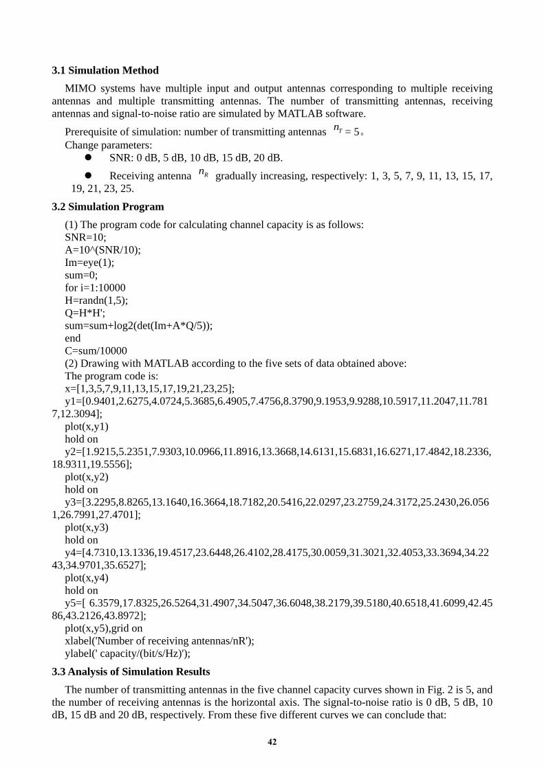
3.3 Analysis of Simulation Results The number of transmitting antennas in the five channel capacity curves shown in Fig. 2 is 5, and
the number of receiving antennas is the horizontal axis. The signal-to-noise ratio is 0 dB, 5 dB, 10 dB, 15 dB and 20 dB, respectively. From these five different curves we can conclude that:
42

When the number of transmitting antennas is constant and the signal-to-noise ratio is constant, the channel capacity increases with the number of receiving antennas.
The number of transmitting and receiving antennas is the same, and the channel capacity increases with the increase of SNR.
Channel capacity mainly depends on the SNR of the system and the number of antennas, and has little effect on bandwidth and antenna transmission power.
Fig2 MIMO simulation result
In summary, the channel capacity increases linearly with the increase of antenna number, that is to say, without increasing the bandwidth and antenna transmission power, the capacity of wireless channel can be doubled by MIMO channel, which proves the correctness of MIMO channel system theory and achieves the requirements of this design.
4. Conclusions MIMO technology is one of the key technologies of LTE system. The simulation results above
show that MIMO technology has a good advantage in improving channel capacity. However, if the transmitting antenna and receiving antenna are continuously increased, the channel capacity can be increased, but at the same time, the complexity of system design will also be brought. Therefore, the transmitting antenna and receiving antenna can not be increased blindly, and the site requirements and construction costs need to be considered comprehensively. This will be the content of further research in the future.
References [1] Wu Weiling, Niu Kai. Principles of Mobile Communication. Electronic Industry Press. [2] Wutong Zhang. Introduction to MIMO Communication Technology [J]. Science Weekly, 2013 (5). [3] Pang Qinhua, Wu Weiling, Yang Hongwen. Principles of Communication. Beijing University of Posts and Telecommunications Press. [4] Chen Yuheng, Xiao Zhu, Wang Hong. LTE protocol stack and signaling analysis. Beijing People's Posts and Telecommunications Publishing House, 2013. [5] Zhao Xunwei, Lin Hui, Zhang Ming. Long Term Evolution (LTE) System Architecture and Technical Specification. Beijing: People's Posts and Telecommunications Press, 2010. [6] Wang Yingmin, Sun Yunhui. TD-LTE Technology Principle and System Design. Beijing: People's Posts and Telecommunications Press, 2010. [7] Peak, Gao Zehua, Fenglei. TD-LTE Technical Standards and Practice. Beijing: People's Posts and Telecommunications Publishing House, 2011.
43