OF - NASA NASA Single Cell Test, Scheme B; Photograph. 14 Life History, Cell No. A-027. 25 Life...
76
- - NASA CR- 72 178 I I I I SEMIANNUAL REPORT DEVELOPMENT OF FUEL CELL ELECTRODES by M. B. ClarkandG. E. Evbns prepared for I I I I I I I I NATIONAL AERONAUTICS AND SPACE ADMINISTRATION December 31, 1966 CONTRACT NAS 3-9430 Technical Management NASA Lewis Research Center Cleveland, Ohio Space Power Systems Division W. A. Robertson UNION CARBIDE CORPORATION ELECTRONICS DIVISION Fuel Cell Department P. 0. Box 6116 Cleveland, Ohio 4410 1 https://ntrs.nasa.gov/search.jsp?R=19670010589 2018-05-20T13:38:22+00:00Z
Transcript of OF - NASA NASA Single Cell Test, Scheme B; Photograph. 14 Life History, Cell No. A-027. 25 Life...

- -
NASA CR- 72 178
I I I I
SEMIANNUAL REPORT
DEVELOPMENT OF F U E L CELL ELECTRODES
by
M. B. C l a r k a n d G . E. Evbns
prepared for
I I I I I I I I
NATIONAL AERONAUTICS AND SPACE ADMINISTRATION
December 31, 1966
CONTRACT NAS 3-9430
Technical Management NASA Lewis Research Center
Cleveland, Ohio
Space Power Systems Division W. A. Robertson
UNION CARBIDE CORPORATION ELECTRONICS DIVISION
Fuel Cell Department P. 0. Box 6116
Cleveland, Ohio 4410 1
https://ntrs.nasa.gov/search.jsp?R=19670010589 2018-05-20T13:38:22+00:00Z

TABLE O F CONTENTS
U I I I I I 1 II
LIST O F FIGURES . . . . . . . . . . . . . . . . . . . . . . . . . . . . . .
LIST OF TABLES . . . . . . . . . . . . . . . . . . . . . . . . . . . . . .
ABSTRACT . . . . . . . . . . . . . . . . . . . . . . . . . . . . . . . . . .
SUMMARY . . . . . . . . . . . . . . . . . . . . . . . . . . . . . . . . . .
INTRODUCTION . . . . . . . . . . . . . . . . . . . . . . . . . . . . . . .
FACTUAL DATA . . . . . . . . . . . . . . . . . . . . . . . . . . . . . . .
Task 1 . Electrode Improvement . . . . . . . . . . . . . . . . . . . .
B . C. ell Design . . . . . . . . . . . . . . . . . . . . . . . . C . Test Fac i l i t i es . . . . . . . . . . . . . . . . . . . . . .
Summary of Large-Cell Data . . . . . . . . . . . . .
3 . Cel l Life . . . . . . . . . . . . . . . . . . . . . . . . 4 . Current-Voltage Relationships . . . . . . . . . . . . 5 . Effects of Temperature and P r e s s u r e . . . . . . . . 6 . Cel l Resistance . . . . . . . . . . . . . . . . . . . .
E . Materials Testing . . . . . . . . . . . . . . . . . . . . . 1 . Cell Mater ia ls . . . . . . . . . . . . . . . . . . . . . 2 . Porous Teflon . . . . . . . . . . . . . . . . . . . . .
A . Electrode Types . . . . . . . . . . . . . . . . . . . . . .
D . Experimental Results . . . . . . . . . . . . . . . . . . . 1 . 2 . Catalyst Loading . . . . . . . . . . . . . . . . . . .
Task 2 . Pre l iminary System Design . . . . . . . . . . . . . . . . . . PLANS FOR FUTURE WORK . . . . . . . . . . . . . . . . . . . . . . . . APPENDIX A . . . . . . . . . . . . . . . . . . . . . . . . . . . . . . . . APPENDIX B . . . . . . . . . . . . . . . . . . . . . . . . . . . . . . . .
Page
ii
iii
1
1
4
6
6
6 7
10
15
15
22
2 4
27 30
33
34
35
3 9
4 6
4 9
51
5 4
DISTRIBUTION LIST . . . . . . . . . . . . . . . . . . . . . . . . . . . . .

Fig . No.
1
2a
2 b
3
4
5
6 7
8
9 10
11
12
13
14
15
16
17
18
19 20
21
22
23
24 '
LIST OF FIGURES
Title Page
C lose -up of Single C e l l . 8
4" x 4- 1/2" Tes t C e l l . 9 4" x 4-1/211 P r e s s u r e Test C e l l . 9 Tes t Cel l Components: (a) Electrode; (b) Electrolyte 9 Separator ; (c) Gas Spacer.
NASA Single Cel l Test , Scheme A; Diagram. 10
NASA Single Cell Tes t , Scheme A; Photograph. 11
NASA P r e s s u r e Cell Test Scheme; Diagram.
-
12
NASA P r e s s u r e Cell Test Scheme; Photograph. 13
NASA Single Cel l Tes t , Scheme B; Diagram. 14
NASA Single Cel l Tes t , Scheme B; Photograph. 14
Life History, Cel l No. A-027. 25
Life History, Cel l N o . A-029. 25 Life History, Cel l N o . A-014. 26 Life History, Cell No. A-015. 26 Life History, Cel l N o . A-018. 27
Current-Voltage Data for Ceil Nos . A-027 and A-029. 2 8
Current-Voltage Data f o r Cel l No. A-014. 28
Current-Voltage Data f o r Ce l l No. A-015. 29 Current-Voltage Data f o r Cel l No. A-018. 29 Temperature-Electrolyte Concentration Effects (Cell No. A-0 13). 3 1
Terminal Voltage Versus P r e s s u r e . 32
Electrode Polarization Versus P r e s s u r e . 32
NASA 5-KW System 24-Hour Load Duty Cycle (Cycle Repeats 46 Every 24 Hours) .
NASA 5-KW System Polarization Curves. 48
Acoustic Noise Frequency Spectrum . 52
.. -11-

Table No.
I I1
I11 IV
V
VI
v I1
VIII
IX
X
XI
XI1
XI11
XIV
xv XVI
xv I1
LIST O F TABLES
Title - Cell Descriptions.
Summary of Cel l Data a t 200 ASF, 15 psia.
Summary of Electrode Data - 200 ASF, 15 psia.
Cel ls with Highest IR-Free Potentials (200 ASF, 15 psia)
Post-Catalysis of Type-5 Cathodes.
P r ecataly s i s of Type - 5 C athodes . IR-Drop Measurements -NASA Cells -200 ASF, 15 psia.
Mater ia ls Compatibility Tes t s . Gold Pla te Deposit - Collector Mesh.
P o r e Size Measurements.
Chemplast-Extra Fine-Zitex E1002- 15.
Chemplast-Fine- Zitex E-606A- 122.
C h em pla s t - Medium -As Re c eiv ed . C h emplas t - Medium - P r e sh runk.
Chemical Rubber- 150 mm-Medium.
Stack Design.
System P a r a m e t e r s .
Page
16-18
19 20
21
22
22
34
35-37
38
39
41
42
43
44
45
47
47

DEVELOPMENT OF FUEL CELL ELECTRODES
by M. B. Clark a n d G . E . Evans
Union Carbide Corporation
ABSTRACT
The applicability to aerospace requirements of a fuel cel l sys tem employ-
ing circulating liquid electrolyte and water removal v i a t ranspirat ion through
porous electrodes is being investigated.
repor t concerns upgrading of electrode and ce l l performance.
ce l l constructed to date has operated a t 200 ASF continuously for 800 hours a t
a tmospheric p re s su re with a constant terminal voltage of 885 *5 mv, with the t e s t
s t i l l in progress .
Most of the effort covered in the present
The bes t (4" x 511)
SUMMARY
Work under the present program is divided in two areas. The first a r e a
of work is the performance improvement of Union Carbide Corporation fuel cel l
e lectrodes.
tion will b e a s ses sed .
cap ib le of rrperating at 200 amperes per square foot at an initial terminal voltage
of at leas t 0. 900 volt, and having a terminal voltage decline of not m o r e than 0 . 020
volt a f te r 500 hours of continuous operation a t 200 a m p e r e s / s q . f t .
a r e a of work has as its cbjective the evaluation of the Union Carbide sys tem con-
cept.
2 9 *2 volts with a design l ife of 3000 hours .
The effect of increased catalyst loading and improved cur ren t collec-
The goal of this effort i s the development of electrodes
The second
The reference sys tem shall be a nominal 5-kilowatt sys tem operating at
Two technical approaches a r e being followed in the Task 1 - Electrode
Improvement phase of the program.
the Union Carbide Type T-2 electrode (catalyzed carbon on porous nickel) through
the use of m o r e effective, higher catalyst loading and higher conductivity subs t ra tes
to reduce ce l l internal res is tance. A second approach is to employ highly catalyzed
electrodes of the types al ready qualified fo r u se in matr ix- type aerospace sys t ems ,
with modifications in s t ruc ture to permit use in a circulating electrolyte sys tem.
Both approaches have led to useful electrodes, falling within the performance r e -
quirements established for the electrode improvement program.
ce l l constructed to date has operated at 200 ASF continuously fo r 800 hours a t a constant te rmina l voltage of 885 k5 mv a t a tmospheric p re s su re , with the t e s t still
in p rogres s .
C ompany .
One approach is to upgrade performance of
The bes t (4" x 5 " )
This cel l employs LAB-40 electrodes obtainedfrom American Cyanamid
1

These electrodes show excellent voltage charac te r i s t ics but have occasion-
ally failed during shutdown and r e s t a r t of a tes t . The fai lure mode appears to be
delamination of the Teflon facing f rom the active electrode a s a resu l t of thermal
s t r e s s . These electrodes a l so show a tendency to "weepage" (formation of liquid
droplets on the gas face of the electrode) which appears to be related to nonuniform-
i ty in the pore s t ruc ture of the Teflon. The vendor is modifying his electrode fab-
rication techniques to obtain better bonding and s t ruc tura l uniformity in the Teflon
facing, and will supply improved electrodes for testing.
Union Carbide Type T-2 electrodes (carbon on thin porous nickel) show
excessive voltage degradation when used as a cel l cathode a t 100°C and 200 ASF.
These Type T-2 electrodes, however, show excellent voltage stability when used
as anodes, at potentials comparable to the LAB-40 anodes. Since the T-2 anodes
remain d ry on the gas face at 200 ASF (no "weepage") and a r e not damaged by
sudden ce l l shutdowns, they a r e the preferred anode a t the present t ime.
Experiments with pressur ized ce l l s have shown that operation at 30 psia
(15 psig) adds about 30 mv to the terminal voltage at 200 ASF, giving initial t e r -
minal voltages above 0. 92 volt. Fur ther increases in p r e s s u r e to 45 and 60 psia
produce relatively slight additional voltage gains.
by higher p r e s s u r e s in the design of water removal equipment, a 30 psia design
point appears to be c lose to optimum.
Considering problems introduced
Experimental study of the effects of tempera ture (up to 130°C) on cell pe r -
formance have shown, as expected, that higher i e r n i i n d voltages can b e achieved
a t higher tempera tures . Unfortunately, at tempera tures above about 100°C the
electrolyte concentration must be increased to the 13 - 15 M range to maintain an
acceptable vapor p re s su re . Operation with such concentrated electrolyte introduces
major problems in the design and operation of a pract ical sys tem, due to the danger
of electrolyte f reeze-up on cooling to ambient tempera ture during intermittent oper -
ation.
ma te r i a l s ' stability, and s ince acceptable voltage levels can be achieved in the
90 - 100°C range, this lower temperature range has been chosen for the design study.
Since high tempera ture operation a l so magnifies problems of cor ros ion and
The ma te r i a l s ' testing program has identified a list of ma te r i a l s acceptable
for u se in KOH electrolyte at 100°C under oxidizing conditions. It has been found
that generic names fo r plastic mater ia l s , such a s "polypropylene, ' I
o r "Nylon" a r e completely inadequate designations in selecting fuel
ma te r i a l s . F o r example, one grade of polypropylene disintegrates
"neoprene",
ce l l s t ruc tura l
within a week
2

upon testing in KOH electrolyte a t 100°C, while another shows no significant
effects.
the functional requirements of the fuel cel l s t ruc tura l design (e. g . , f raming
ma te r i a l s , encapsulants, adhesives, gaskets , s epa ra to r s , sealants , etc. ), but
in s o m e instances not in the des i red physical fo rm.
qualified ce l l mater ia l s , defined with respect both to physical s t ruc ture and
chemical identity, is scheduled f o r completion within the present contract period.
At lease one "acceptable" mater ia l is available for fulfilling each of
Establishment of a list of
Work under the Task 2 - Pre l iminary System Design study has just been
initiated.
cer ta in of the components of the Union Carbide Fuel Cel l sys tem to a s s u r e
compatibility with aerospace environmental requirements , in par t icular ze ro -
gravity operation.
The major effort under this Task will b e the redesign in concept of
Components which require modification f rom previous terrestrial designs
include a partitioned electrolyte-expansion tank to prevent an unstable liquid-gas
interface; a liquid-gas separa tor to remove fortuitous gas bubbles in the electro-
lyte a r i s ing f rom dissolved reactants o r peroxide decomposition; and a "wicking"
type condenser to remove water f rom the circulating gas s t r eams .
Severa l of these design problems a r e similar to problems previously
faced and solved in the design of previous aerospace fuel cel ls o r l ife-support
sys tems.
negotiated with Gar re t t Corporation for design of the Thermal Control Subsystem
of the proposed fuel cel l system.
On the bas i s of pr ior experience in this field, a Subcontract is being
3

I 1 I I I I I 1 I N 1 I I I 1 1 I 1 1
INTRODUCTION
Over a period of about 15 years , Union Carbide has developed a unique
type of fuel cel l system. While details of electrode fabrication and system com-
ponent design have been modified over the yea r s , cer ta in cent ra l design concepts
have remained constant and can be considered a s defining the "Union Carbide
system" design. These features include:
a) Use of a circulating aqueous KOH electrolyte as the pr imary means
of hea t removal;
b) Recirculation of one o r both of the reactant gases a s a means of water removal via t ranspirat ion through the porous electrodes;
c ) Operation under conditions of t empera ture , p re s su re , fluid flow r a t e s ,
electrolyte concentration, etc. , which provide self-regulating control of the
water balance;
d) Stabilization of the three-phase electrochemically active zone through
control of pore geometry and wetting angle in s emihydrophobic e lectrodes,
a s a means of broadening the range of gas-electrolyte differential p r e s s u r e s
within which stable operation can be achieved;
e) Use of carbon a s the principal active ingredient of the electrodes, with
minimal amounts of additional catalysts, as a means of reducing cost .
F o r brevity i n the following discussion, the design fea tures descr ibed in
a) through e) above will be r e fe r r ed to as the "Union Carbide sys tem concept".
The guiding philosophy in developing this system concept has been to minimize
the sys tem cost per kilowatt a t a commercial ly useful level of power density,
and to reduce the sys tem complexity to a minimum number of (preferably static)
components.
leads to a sys t em of l imited utility in anticipated aerospace missions, where min-
imum sys tem weight becomes of cr i t ical importance.
leading to the present program was to demonstrate the applicability of the Union
Carbide sys tem concepts to aerospace mission requirements , on the bas i s of
new trade-off c r i t e r i a between system cost, performance and reliabil i ty. The
major problem, in broad t e r m s , was to develop and demonstrate a major improve-
ment in performance (as measured by power density and energy density) without
loss in reliability o r life.
Optimization with pr imary emphasis on cost p e r kilowatt, however,
The original motivation
4

I I 1 I I i 1 I 1 I I 1 I I 1 I I I I
It was immediately apparent that i t would be necessary to improve the
electrode performance to permit operation a t higher voltage and higher cur ren t
density.
tion over 500 hours was selected to guide this phase of the effort.
w e r e selected, to be followed in parallel.
available Union Carbide Type-2 electrode (thin porous carbon supported on porous
nickel) , and to upgrade the performance by increasing the catalyst level and
increasing the conductivity of the electrode. A second approach was to s t a r t
with heavily catalyzed (platinum) electrodes of the types al ready qualified for
high performance matrix cel ls and modify the s t ruc ture s o a s to pe rmi t operation
in circulating electrolyte ce l l s .
A goal of 0 . 900 volt terminal at 200 ASF with l e s s than 20 mv degrada-
Two approaches
One approach was to s t a r t f rom the
I t rapidly became apparent that in o rde r to reach the electrode performance
goal it would be necessary to increase the operating tempera ture f r o m the 60-80°C range to the 80- 100°C range. This increase in tempera ture improves polarization
and reduces cel l internal res i s tance , and equally important, reduces the weight
of the space radiators required for heat rejection.
i nc rease in temperature , however, some of the commonly employed mater ia l s
of construction become marginal in stability in contact with hot KOH.
As a consequence of this
To e c s u r e stability of mater ia ls of ce l l construction within the new oper -
ating conditions, a mater ia l s compatability testing study has been incorporated in
the P h a s e 1 program.
14 N KOH under oxidizing (atmas2heric a i r environment) conditions at 100°C for
one week. Samples a r e checked for dimensional o r weight changes, appearance
changes, loss of physical propert ies (embri t t lement , softening, erosion, etc. ) .
The electrolyte is a l so examined for evidence of chemical contamination, change
in sur face tension, etc.
The "f i rs t screen" consists of exposure of the sample to
The second phase of the present program is a prel iminary design study.
This re-examination of the design concepts has two aims: first , to account properly
fo r the unique environmental conditions of aerospace missions; and second, to
redesign to new internal operating conditions of tempera ture , p re s su re , and
electrode polarization.
Env i r onm ental conditions of pr imary s ignif i c anc e inc lud e z e r o - g operation,
space vacuum, and launch shock, vibration, and acoustic nois e specifications.
Zero-gravi ty operation influences the design of a number of components. The
no rma l method employed fo r water removal is condensation f r o m a circulating
gas s t r eam; in the absence of gravity this requi res some f o r m of "wicking condenser"
5

I I I 1 1 1 I 1 I I I I 1 I 1 I I 1 1
to collect and t ranspor t liquid water in a capillary wick.
been built and successfully tested, no major problems a r e anticipated beyond sizing
components to match the load profile. Operation of a liquid electrolyte circulation
loop under z e r o gravity conditions will a l so requi re some s o r t of device for isola-
tion and rejection of gas bubbles in the electrolyte.
f r o m differences in solubility of reactant gases in the electrolyte under thermal
cycling o r f r o m decomposition of peroxides which escape the normal catalytic reaction
a t the electrode surface. Two approaches a re being considered; in one, a highly
hydrophobic porous membrane permits gas penetration while blocking liquid flow;
in a second approach, a mechanical centrifuge separa tes gas and liquid phases.
Engineering study will be required to determine which approach offers the highest
reliabil i ty and lightest weight af ter feasibility has been established.
Since such devices have
Such gas bubbles can originate
A third component which i s significantly influenced by zero-gravi ty operation
is the electrolyte reservoir-expansion chamber .
ent i re electrolyte inventory during periods of high acceleration and to accommodate
electrolyte volume changes caused by thermal expansion and normal electrolyte
concentration variations.
tolerance is accommodated in a simple expansion tank; under zero-gravity opera-
tion a bellows o r flexible bladder is required to prevent an unstable gas-liquid
interface and to allow gaging of the electrolyte volume.
This unit is needed to s t o r e the
Under t e r r e s t r i a l operating conditions the expansion
Operation in space vacuum introduces the requirement of establishing an
absoiute p r e s s u r e reference rather than sim-ply balancing p r e s s u r e s against an
atmospheric ambient p re s su re . This problem has been successfully solved for
s eve ra l existing aerospace fuel cel l types, and no difficulty is anticipated in
adapting existing techniques to the present sys tem.
FACTUAL DATA
Task 1 - Electrode Improvement.
A. Electrode Types.
Most of the tes t p rogram has been centered on three general types of Union
Carbide fuel cell electrodes, plus one type obtained f r o m American Cyanamid, as
descr ibed below:
1. Type-2 Electrodes: Active carbon on porous meta l (a) catalyzed af ter
fabrication, (b) carbon precatalyzed before fabrication.
2. Type-5 Electrodes: Active carbon on meta l sc reen; Teflon-backed;
carbon usually pr ecatalyzed befor e fabrication.
6

I I I I I 1 I I 1 I I I 1 I I I I 1 I
3 . American Cyanamid, LAB-40 electrodes, 40 m g P t / c m 2 on nickel
s c reen with Teflon backing.
A limited number of tes t s have been conducted on other experimen-
tal electrode types, including electrodes supplied by ChemC ell.
4.
Electrode improvement has consisted largely of tes ts directed toward:
1. Increasing the catalyst concentration, either by post-catalysis o r
precatalysis of the active carbon;
Improving the electr ical conductivity by substitution of s i lver for
nickel, and by improving the bonding of the active electrode mater ia l
to the metal substrate , and
Reducing the electrolyte "weeping" problem (i. e . , the formation of
beads of moisture on the g a s s ide of the electrode).
2 .
3 .
B. Cel l Design.
Some of our preliminary screening t e s t s have been run in small (2. 0 cm2)
active a r e a ) cells.
mounted in injection-molded polyethylene f r ames which, together with other required
cel l components (electrolyte compartment and gas chambers) , are simply clamped
together and mounted on a t e s t rack provided with means for circulating heated
electrolyte.
These a r e very easily assembled, consisting of electrodes
F igure 1 shows a cell of this type.
In this f igure the ce l l is designated by the le t ter l'Brt . Electrolyte is c i r -
culated through the cell by means of a "bubble-pump" using nitrogen as propellent.
The bulk of the electrolyte i s contained in a reservoi r "G" containing a car t r idge
hea ter "H". Electrolyte is gravity fed to the cel l through tube l 'C' ' and overflows
f r o m the top of the cel l through tube ''E, I ' where i t flows into a tee.
flow of nitrogen into one s ide a r m of the t ee lifts the electrolyte back up to the
r e se rvo i r .
A constant
Most of the testing has been done with larger cells with an active electrode
After some prel iminary work a fair ly standarized
The necessi ty fo r operation tempera tures to 100°C
a r e a of 0. 125 ft2 (,I1 x 4-1/2"). construction has been evolved.
required some modifications of the usual cel l type.
cel l of the type being used a t present.
details , but encased in a rigid Panelite body to make it suitable fo r p r e s s u r e testing.
F igure 2a shows a finished
Figure 2b is a cell similar in all internal
In most cel ls the electrodes have been f ramed with s t r ip s of s i lver held in
place with conductive silver-epoxy res in (F ig . 3a). when porous nickel is used as a backing mater ia l (Type-2 electrodes) , as well as
This is particularly important
7

I I I 1 1 I I I I I i R I I I I I I I
A
B
Fig. 1 - Close-up
KOH Head Tube
C ell
D-736 of Eingle Cel l
C XOFI Inlet Tube to Cell
c Nitrogen
E C ell Overflow
F F r o m Overflow to Keservoir
G KOH Reservoir
H Heater Cheath
J Nitrog en fi4anif old

D-3144 Fig. 2a - 4" x 4-1/2" Test Fig. 2b - 4" x 4-1/2" F r e s s u r e -
C ell. v
C ell.
Fig. 3 - Tes t Cei i Components: ( a ) Electrode; (b) E lec t ro- lyte Separator ; (c) Gas Spacer .
D-3146
9

with the Type-5, andtheLAB-40 e l e c t r o d e s . A cur ren t tab in the form of a
T - b a r of heavy (26-mil) s i lver is cemented to one edge.
The best separa tor mater ia l loGnd s o f a r has been expanded Nylon (Exmet
Code 10, 25-1, stabil ized); see Fig. 3b. Because i t has a "memory, and will
contract a t the higher ce l l temperatures used in this program, i t has been neces-
s a r y to anchor i t at the edges with epoxy.
the two electrodes, and the electrolyte gap of approximately 50 mi ls is defined
by means of narrow neoprene s t r ip s cemented along the electrode edges which
s e r v e as a gasket.
This separa tor is sandwiched between
The gas space behind each electrode is defined in a similar manner , but
the space r mater ia l (used to hold the electrodes f i rmly against the electrolyte
sepa ra to r ) has usually been Lamport Style No. 7700 polypropylene mesh approx-
imately 90 mi ls thick (Fig. 3c).
Polysulfone shee t was chosen as the outside ce l l casing ma te r i a l fo r mos t
of the ce l l s , replacing the Lucite customarily used because of the higher operating
tempera tures . All components a r e cemented together with epoxy res in , and the
final ce l l edges "potted" with this mater ia l .
por ts a r e machined f r o m polysulfone and cemented in place a s a final step.
Electrolyte and gas inlet and outlet
C . T e s t Faci l i t ies .
Since tempera tures in the vicinity of 100°C were to be employed, modifica-
tion in our usual t e s t facil i t ies w a s necessary .
used f o r much of this prel iminary work is ahown schematically in Fig. 4, and
a photograph is shown in Fig. 5.
A simple t e s t stand of the type
1 - Thermometer
+- Shut-Off Valve
Manometer
Note: Single gaa flow shown. H, and 0, mymternl are Identical.
L iqud Trap L Condedaate Receiver
Fig. 4 - NASA Single Cel l Tes t , Scheme A.
10
D-3122

D-3119
Fig. 5 - NASA Single Cell Test , Scheme A,
In this arrangement the KOH reservoi r (1) is constructed of nickel, and
heated by means of heating tape.
centrifugal pump (2) , entering the bottom of the cell ( 3 ) , and exiting at the top
f r o m where it re turns to the reservoir .
a r e identical, only one is shown in the schematic, and only the oxygen loop i s
identified in the photograph.
the cell a t the top.
culation is provided), and leaves the cell f rom the bottom, the exit port being
positioned diagonally a c r o s s f rom the inlet port . The exit gas pas ses through
a water-cooled condenser (5) which serves to remove a major portion of the
water , which then collects in the condensate rece iver (6). a s a t r ap to detect the presence of electrolyte leakage should it occur.
gas finally passes through a control valve positioned on one leg of a U-tube
containing mercu ry (7).
The electrolyte is circulated by means of a
Since both gas circulating sys tems
Each gas f i r s t enters a flowmeter (4), then enters
All excess gas i s purged f r o m the system (i. e. , no r ec i r -
The la t te r a lso acts
The exit
This permits control of the g a s p r e s s u r e i n the cell.
Also shown in the photograph is the Var iac (8) used for adjusting elec-
trolyte temperature , an electrolyte level probe (9) which automatically shuts
off the hydrogen supply and puts the cell on open c i rcu i t in the event that the
electrolyte level were to become dangerously low, and the components of the
load circuit : vol tmeter ( l o ) , ammeter ( l l ) , and rheostat (12).
11

In addition to five t e s t positions of the foregoing type, one position suitable
The schematic and photo-
P r e s s u r e balance is achieved by
fo r operating a t p r e s s u r e s up to 45 psig has been built.
graph of this sys tem are shown in Figs . 6 and 7 .
simultaneous pressurizat ion of the electrolyte with nitrogen as the hydrogen and
oxygen p r e s s u r e s a r e increased.
gen to one s ide of the diaphragm of both the hydrogen and oxygen regulators ( l ) , Fig. 7;
only one gas sys tem is indicated in the f igures .
gases to "follow" the nitrogen pressure .
maintained a t a value slightly above that of the nitrogen by means of spr ings in
the regulators .
to that descr ibed for the previous system.
This is easily accomplished by feeding the ni t ro-
This fo rces the p r e s s u r e of these
The hydrogen and oxygen p r e s s u r e s a r e
The electrolyte reservoi r (2) and pump (3) arrangement is similar
T Thrrmomrlrr
& Flow-Control V a l v e r\
-+ . Shut-Off Valvr
Snlcnnrd P r r l l u r r
I t 0 Condenser
Liquid Trap k Condenaatr Receiver
D-3124
Fig. 6 - NASA P r e s s u r e Cel l Tes t Scheme.
In addition, a second tank (4) was installed above the ma in r e se rvo i r . This
can be isolated f rom the system by means of valves above and below, and provides
a means for adding electrolyte to the pressur ized sys tem, if des i red .
tanks a r e provided with se rv ice openings (normally plugged).
t rode readings a r e required, the electrode (a Zn wire) is inser ted direct ly into
the main KOH rese rvo i r .
Both of these
When re ference elec-
12

D-3118
Fig. 7 - NASA P r e s s u r e C,ell Tes t Scheme.
Each exit gas passes through a condenser and t r a p (5)-stainless steel- i n
The flow ra t e i s adjusted by means a manner similar to that already described.
of a control valve ( 6 ) , and measured by a flow me te r (7) at the discharge end of
the line. A continuous purge of nitrogen is also maintained through valve (8) and
flow m e t e r (9) which prevents the accumulation of hydrogen and oxygen above the
electrolyte.
Safety features were provided to completely shut down the system, in
the event of l o s s of nitrogen p r e s s u r e o r drop i n electrolyte level, by means of
a p r e s s u r e switch in the nitrogen l ine, solenoid valves i n all of the gas l ines , and
a probe i n the electrolyte reservoi r .
Six additional t e s t facil i t ies a r e in use, p r imar i ly for life testing of single
These have been somewhat more elaborately instrumented. F igu res 8 and cells.
9 show the schematic and photograph of this facility. Identifying numbers i n Fig. 9
a r e as follows: (1) fuel cell; (2) heated electrolyte reservoi r ; ( 3 ) inst rument panel
containing p r e s s u r e regulators , f lowmeters, gages, vol tmeter , and ammeter ;
(4) condenser (exit gas l ine) , and (5) condensate receiver .
13

1 - Temperature Probe
id.ntic.1.
D-3123
Fig. 8 - NASA Single Cel l Test, Scheme B.
D-3120 Fig. 9 - NASA Single Cel l Test, Scheme B,
14

D. Experimental Results.
1.
The bulk of the testing to date has been done with 4" x 4-1/2" (0. 125 f t . 2,
Table I lists the cel ls which have been built and (with the exception of a
Summary of La rge Cel l Data.
cel ls .
few) tes ted to date. The electrode types, additional cu r ren t col lectors , and
electrolyte separa tors a r e designated by numbers descr ibed in the footnotes
following the table. The t e r m "additional cur ren t collectors" re fers to a meta l
member in addition to the porous metal o r s c reen which fo rms an integral par t
of the electrode.
In the case of electrodes made with precatalyzed carbon, the catalyst
levels a r e ra ther approximate since there was some variation in electrode thick-
nes s , and the values were not calculated for each individual electrode.
Table I1 summar izes all of the cell data obtained at a cu r ren t density of
In some cases cel ls were operated for additional periods at lower 200 ASF.
cu r ren t densit ies, but these data a r e not included he re . Likewise, cel ls which
w e r e operated a t cur ren t densities other than 200 ASF a r e omitted.
and IR-free voltage data were obtained.
means of a Kordesch-Marko bridge-widely used for this type of measurement .
Both te rmina l
The la t ter values were measured by
Table I11 presents IR-free cathode and anode data (versus a zinc wi re
reference electrode).
t rode type ra ther than CGES ccutively.
F o r convenience, these data a r e l isted according to elec-
The voltage data in Tables I1 and 111 a r e l isted a s "initial, "peak, and
"final".
to the l a s t ones taken before the t e s t was terminated (or the load reduced)-usually
on the l a s t t e s t day.
t e s t period. Cell , anode, and cathode peak values do not, of course, necessar i ly
fall on the s a m e tes t day.
Initial values were usually taken on the f irst t e s t day; final values r e fe r
Peak values refer to the "best" values measured during the
The electrode performance goal of 900 mv terminal voltage with 20 mv
o r l e s s voltage degradation tolerable over a 530-hour period at 200 ASF, in effect,
establishes a "cut-off" voltage of 880 mv as a minimum acceptable value. Of the
ce l l s tabulated in Table 11, only Cel l A-015 has remained above 880 mv for over
500 hours ; this cel l is operating above 880 mv af ter m o r e than 800 hours , with the
t e s t still in progress .
cathodes, were conducted for the purpose of obtaining specific experimental infor-
Many of the tes ts , in par t icular all of those employing Type-2
15

TABLE I
C E L L DESC RIP TIONS
Catalyst Cel l Electrode Level Additional Curren t - Electrolyte - No. Types ( m g l cm’) Collector Types Separator Types A-001
A-002
A-003
A-004
A-005
A-006
A-007
A-008
A-009
A-0 10
A-011
A-0 12
A-013
A-014
A-015
A-0 16
A-017
A-018
2 - 1 Cathode 1 . 0 2 - 1 Anode 2 . 5
2-2 Cathode 8. 0 2 - 2 Anode 8. 0
2 - 2 Cathode 8. 0 2 - 2 Anode 8. 0
2-1 Cathode 1 . 0 2 - 1 Anode 2 . 5
2-3 Cathode -5. 0 2-3 Anode -5 .0
LAB -40 Cathode 40. 0 LAB -40 Anode 40. 0
3-1 Cathode 4 . 0 2-1 Anode 2 . 5
5- 1 Cathode 1. 0 2 - 1 Anode 2. 5
2-1 Cathode 1 . 0 2 - l A Z d e 2 . 5
2-1 Cathode 1 . 0 2-1 Anode 2 . 5
2-3 Cathode -5.0 Modified AB-40 Anode 40.0
4 - 1 Cathode 1.0 2 - 1 Anode 2. 5 LAB -40 Cathode 40. 0 LAB-40 Anode 40. 0
LAB-40 Cathode 40.0 LAB-40 Anode 40.0
LAB -40 Cathode 4 0 . 0 LAB-40 Anode 4 0 . 0
2-3 Cathode -5.0 2 - 1 Anode 2 .5
5-3 Cathode -5.0 2-1 Anode 2 .5
LAB-40 Cathode 4 0 . 0 LAB-40 Anode 40. 0
(Continued)
1.6
1 1
None None
2 2
1 1
3 3
3 3
3 3
2 2
2 2
2 2
2 2
4 2
2 2
3 3
2 2
3 2
3 2
3 3
1
1
1
2
2
2
2
2
2
3
4
4
2
2
2
2
2
2

TABLE I
(Continued)
Cel l No.
A-019
A-020
A-02 1
A-022
A-023
A-024
A-025
A-026
A-027
A-028
A-029
A-030
A-031
A-032
A-033
A-034
A-035
A-036
Elect rod e Types
LAB -40 Cathode LAB-40 Anode
LAB-40 Cathode LAB-40 Anode
LAB -40 Cathode LAB-40 Anode
LAB-40 Cathode LAB-40 Anode
LAB -40 Cathode LAB-40 Anode
2-4 Cathode 2- 1 Anode
2-4 Cathode 2 - 1 Anode
5-4 Cathode 2-1 Anode
5-4 Cathode 2- 1 Anode
LAB-40 Cathode LAB-40 Anode
5-4 Cathode 2- 1 Anode
4-2 Cathode 2 - 1 Anode
LAB -40 Cathode LAB-40 Anode
5-4 Cathode 2 - 1 Anode
H9454N Cathode H9454N Anode
5-4 Cathode 2- 1 Anode
H9454N Cathode 2- 1 Anode
LAB-40 Cathode LAB-40 Anode
Catalyst Level Additional Cur ren t - Electrolyte-
(mgl cm2) Collector Types Separator Types 40. 0 40. 0
40. 0 40. 0
40. 0 40. 0
40. 0 40. 0
40. 0 40. 0
-10.0 2 . 5
-10.0 2 . 5
-10.0 2 . 5
* l o . 0 2 . 5
40. 0 40. 0
-10.0 2 . 5
2 . 0 2 . 5
40.0 40.0
-10.0 2 . 5
9 . 0 9 . 0
-10.0 2 . 5
9 . 0 2 . 5
40. 0 40.0
2 2
2 2
2 2
2 2
2 2
None 2
None 2
2 2
2 2
2 2
2 2
4 2 2 2
2 2
3 3
3 3
3 3
2 2
2
2
2
2
2
2
2
2
2
2
2
2
2
2
2
2
2
2
~ ~~~
(See Legend Notes on following page)
17

TABLE I NOTES
Electrode Types:
2-1
2 - 2
2-3
2 -4
3-1
4- 1
4-2
5-1
5-3
5 -4 LAB-40
H9454N
C OT? porous Ni; post-catalyzed
C on porous Ag; post-catalyzed
C on porous Ni; precatalyzed
C on porous Ag; precatalyzed
C on porous Ni (modified s t ruc ture) ; post-catalyzed
C on porous Teflon; post-catalyzed
C on porous Teflon; precatalyzed
C on N i sc reen + Teflon backing; post-catalyzed
C on Ni screen + Teflon backing; precatalyzed
C on Ag sc reen + Teflon backing; precatalyzed
Cyanamid
ChemC ell
Additional Curren t Collector Types:
1 P r e s s u r e contact; Ag screens between electrode and N i collector plate
2 Silver f r a m e and tab
3 Same as 2 , plus Ag screen pressed against face
4 P r e s s u r e contact; sc reen pressed against electrode face and extended a s collector tab
El e c t r olyt e S epar ato r Types :
1
2 Exmet, Code- 10 expanded Nylon, 25- 1 (stabilized)
3 Webril SM9 1 oriented fiber, polypropylene
Lamports Style No. 7700 polypropylene mesh
4 Exmet, expanded polypropylene, 25- 1
18

H W
w 4
t! 9
ai
6 Q 0
Id V
k 0 0 a
" M
I I I I I
9 m a3
0
9 m a3
0
0 r- r- O
9 m a3
0
a3 a3 a3
0
m 0
c- m
d I
m 0 0 I
4
d 0 k a
5
f
fi
0)
al k V c al ED k Id
.A
.r(
J
d
m
a3 m 9
0
9 m I-
0
9 m r- O rr?
9 co 0
9 a3 a3
0
9 m a3
0
N 0, I a3 (r
cr 0 0
4
ai 3 9 k 0 0 a
I I I
I I I I I
I I I I I
a3
r- 0
d
I I
I
I
I I I
" 0 a3
0
a3 o'
In 0 0
4
.A 2
$
2
t al Q
Id U
m 9 N I
a3 N a3
0
cr m a3
0
3 a3
0
9 a3 a3
0
0. * 6
0
9 m m 0
N 0, I
m m
9 0 0
4
6
d
0 k Q
W
E1 .r(
9) a
2 k V c al M k Id
.r(
4
a3 r-
9 N I-
O
9 a3 r- O
9 00 r- 0
4
In a3
0
r(
r- oo 0
9 9 co 0
4
0, I
r- m
0. 0 0
4
k u
64 a O P a d Id k
9 o w m o w . D o o w O d d
I c o m 1 9 w I C O W
1 0 0 I . .
N o 3 0 9 9 0 0 I - c o r n 0 0 0 . . .
N c o O 0 . m m c o c o o . 0 0 0 * . .
I N 0 I M U I 1 6 0 ' I . . I O 0
m 4 0 C O N * o o m 0 ' 0 0 0 . . .
al * V al %I al Q
0 ED
.r( c,
...
i al 4
6)
$. 0 k
V '
U
4
U
02 6:
I I I
I I I I I
I I I I I
lc 9 co 0
I
I I I
I I I I I
0 0 0.
0
4
m I
m a3
m N 0
4
U
$
?
* al al
4
CI
4
0 V al
Tdo 5 Id U
co 1 4
I I I I I
I I I I I
.3 0 a3
0
I
I I I
I I I 1 I
N a3 a3
0
m a3 1
* N 0
4
1 V a al d
6 0 P
. .
k O J a
8 l 3
" K O 0 3 4 N
m o 9 0 a m 0 0
9 9 m o o m a 3 r - c o
0 0 0 . . .
o m a 3 9 o m . . 0 0
m I ( r l a 3 1 . I 0 1
m O N m I n m O o c o o . . . . 0 0 0
19

TABLE III
SUMMARY O F ELECTRODE DATA - 200 ASF, 15 PSIA ( IR-Free Potentials vs. Zinc Reference Electrodes)
Type Cel l No. Initial Peak Final Cathode Data
2 -1
2 -2
2-3 ik 2-4
4-2
5 -3 ik 5-4
LAB-40
2-1
2-2
2-3
LAB -40
A-004 A-009 A-010
A-002 { A-003
A-005 A-0 16 A-024
A-030
A-017 A-026 A-027 A-029
A-006 A-013 A-014 A-0 19 A-023 A-031 A-036
{
{
A-004 A-009 A-010 A-0 16 A-0 17 A-024 A-027 A-029 A-030
A-002 { A-003
A-005
A-006 A-0 13 A-0 14 A-019 A-023 A-031 A-036
I 1
1.377 1. 371 1.394 - - - - - - - - - - - - - - - 1.368 1. 361
1. 347
1.405 1. 384 1.399 1.375
1.420 1.433 1.397 1. 390 1.401 1.455
Anode Data
0.523 0.508 0.513 0.488 0.492 0.481 0.492 0.482 0.499
- - - - _
- - - - - - - - - - - - - - - - - - - - 0. 500 0.491 0.479 0.487 0.481 0.525
1. 392 1. 388 1.409
1. 382 1.393
1.487 1.415 - - - - - - - - - - 1.405 1.413 1.405 1.410
1.436 1.465 1.439 1.410 _ - - _ _ - - - - - - - - - -
0. 507 0. 508 0. 513 0 .488 0.492
0.492 0.482 0 .499
0. 528 0.499
- - - - -
- - - - - 0.487 0.500 0.491 0 .479 - - - - - - - - - - - - - - -
1. 372 1. 376 1.409
0.668 1.249
1. 193
1. 147
1. 310 1. 370 1. 318 1. 390
1. 376 1.364 1.439 1. 385
- - - - -
- - - - -
- - - - - - - - - - - - - - -
0. 513 0 . 532 0.522 0. 558 0 . 591
0.558 0 . 590 0. 517
0.630 0.478
0.685
0 .491 0.508 0.492 0.600 - - - - - - - - - - - - - - -
20

I I 1 I
1 I 1 I II
mation such as the effect of cu r ren t collector type, choice of separa tor , method
of catalysis , etc. As a resul t , mos t of the t e s t s shown in Table I1 were del iber-
ately terminated when the des i red information was obtained. Only two cell t e s t s
to date (Cells A-015 and A-018) have been conducted on the l i fe- tes t racks of the
main testing facility, the remaining tests being conducted on the experimental
t e s t racks of the r e sea rch facility.
be detailed la te r ( in 3. Cel l Life).
Life t e s t data on ce l l s A-015 and A-018 will
A low te rmina l voltage for a cell can imply excessive polarization, high
internal res i s tance within the cell , high cur ren t collector losses , o r m o r e usually,
some combination of these factors . Comparison of the IR-free potentials and
te rmina l voltages shown in Table I1 indicates that an IR drop of 50 mv o r l e s s
can be real ized at 200 ASF.
requi res a difference in electrode potential of 950 mv at 200 ASF.
IR-f ree differences in potential observed thus far, including all values above
900 mv, are listed in Table IV.
To obtain a net 900 m v at the cel l terminals thus
The highest
TABLE IV
CELLS WITH HIGHEST IR-FREE POTENTIALS (200 ASF, 15 PSIA)
IR-Free Cel l No. Type Potentials
A-014
A-006
A-013
A-016
A-026
A-019
A-017
A-027
LAB -40 Cathode LAB-40 Anode
LAB -40 Cathode LAB -49 *Lqode
LAB -40 Cathode LAB-40 Anode
2-3 Cathode 2 - 1 Anode
5-4 Cathode 2 - 1 Anode
LAB -40 Cathode LAB-40 Anode
5- 3 Cathode 2 - 1 Anode
5-4 Cathode 2 - 1 Anode
0. 950v
0.949v
0 . 932v
0. 925v
0. 922v
0 . 9 2 1 ~
0. 913v
0. 907v
~ ~~
The best terminal voltages obtained to date (0. 88, o r be t te r ) w e r e for ce l l s
A-006, and A-014, both with LAB-40 electrodes. On the bas i s of these encouraging
resu l t s , repl icate ce l l s A-015 and A-018 w e r e placed on life test.
21

2. Catalvst Loading.
One of the original objectives of this program was to improve the potentials
of fuel ce l l e lectrodes by increasing the content and effectiveness of the noble
me ta l which s e r v e s a s electrocatalyst .
in s m a l l (2. 0 cm') cel ls a s well a s 4" x 4-1/2" ce l l s , so that a discussion of
this subject will include data of the fo rmer type a s well as that presented in the
tables of the preceding section.
Evaluations have been c a r r i e d out both
In smal l -ce l l testing, both pre- and post-catalysis of cathodes has been
c a r r i e d out.
cm2 levels and tes ted over a 3-day period, showed the 1 mg/crn2 loading to be
poor.
both of which w e r e far superior to the 1 mg/cm2 electrodes ( see Table V).
A s e r i e s of Type-5 cathodes, post-catalyzed a t the 1, 5, and 10 m g /
The 5 mg/cm2 loading was found to be slightly bet ter than the 10 mg/cm2,
TABLE V
POST-CATALYSIS O F TYPE-5 CATHODES
12 M KOH; -80°C; 200 ASF; 3-Day Tes t Duration, 15 psia . . . . . . . . . . . . . . . . . . . . . . . . . . . . . . . . . . . . . . . . . . . . . . . . . . . . . . . . . . . IR-Free Potentials v s . Zinc Ref. (Volts)
Catalyst Loading Initial Peak Final
1 mglcm' (2 tes t s ) 1. 314 1. 314 1.224 1. 326 1. 326 1 .279
5 mg/cm2 (3 tes t s ) 1. 334 1 .405 1 .405 1. 343 1.402 1. 364 1. 344 1.400 1.400
10 rng/cm2 (3 tes ts) 1. 321 1.397 1. 3.97 1. 324 1. 390 1. 384 1.318 1. 380 1. 378
Small-cel l t es t s of precatalyzed cathodes have been conducted at 200 ASF.
Cathodes catalyzed a t approximately the 10 mg/cm2 level have been tested over a
two-week period with encouraging resul ts .
omission of the Teflon backing ( s e e Table VI) .
These were of Type-5 except for
TABLE V I
PRECATALYSIS O F TYPE-5 CATHODES*
12 M KOH; -80°C; 200 ASF; 2-Week Tes t Duration, 1 5 p s i a
Catalyst Loading IR-Free Potentials vs. Zinc Ref. (Volts) -10 mg/cm2 Initial P e a k Final
4 Cel ls Tested 1. 424 1.424 1.422 1.425 1.425 1.415 1. 416 1.416 1. 390 1. 405 1.415 1.404
_ _ _ _ _ _ _ _ _ _ _ _ _ _ _ _ _ _ - _ - - - - - - - - - - - - - - - - - - - - - - - - - - - - - - - - - - - - -
~
:: Teflon backing omitted.
22
Data obtained with large-cel l tes ts , as summarized in Table 111, have also
shown favorable initial performance with precatalyzed cathodes (Types 5-3, and
5-4). The peak values of thesecathodes corresponded fair ly well with those
obtained with the small cel ls (Table VI). ,The r a t e of potential degradation of the
cathode was far higher in 4" x 4-1/2" ce l l s A-017, A-026, A-027, and A-029 (all
employing precatalyzed Type-5 cathodes) than fo r the small t e s t ce l l s l isted in
Table VI.
tial degradation of 280, 26, 17, and 7 mv/100 hours , respectively, compared
with l e s s than 3 mv/100 hours for the cathodes of Table VI. The difference i s
possibly related to the Teflon backing (present in the large-cel l cathodes but
absent in those used in the small cells) .
is questionable at present, and will be discussed la te r .
The cathodes of Cells A-017, A-026, A-027, and A-029 show a poten-
The overal l desirabil i ty of this backing
Post-catalyzed Type 2-1 cathodes gave peak IR-free potentials at 200 ASF
which averaged only slightly lower than the precatalyzed Type-5.
cathodes, however, showed a serious res i s tance problem which will a lso b e d is -
cussed l a t e r , and which makes these look unsuitable a t present .
The Type-2
In general , the bes t overall cathode performance a t 200 ASF and 90-lOO0C
has been achieved by the American Cyanamid LAB-40 electrodes (Table III) which
consis t o€ 40 mg Pt/cm2, Teflon-bonded to a heavy gold-plated nickel s c reen , and
backed with porous Teflon.
Catalysis experiments with anodes have been unrewarding. E a r l i e r work
done pr ior to this contract showed rather conclusivelyy that post-catalysis of
Type-2 anodes above the level of a few mi l l ig rams/cm2 did not improve their
potentials, and that too much catalyst was even detrimental . Precatalyzed
anodes (5 - 10 mg/cm2 range) have been particularly disappointing, and Type-5
anodes (ei ther p re - o r post-catalyzed) have s o f a r been entirely unsuccessful.
The fa i lure of the la t ter type is related to both an over-repel lent electrode surface
(post-catalyzed anodes), and the inability at present to make precatalyzed anodes of
suitable mechanical strength. Fur thermore , the precatalyzed carbon, even when
used in Type-2 anodes, has not looked ve ry promising f r o m an anode-potential
standpoint at 200 ASF.
LAB-40 anodes have been variable in performance. By referr ing to Table I11
data f r o m seven t e s t cel ls can b e examined. Cel l A-006, fo r example, contained an
anode which performed outstandingly. On the other hand, Cel l A-019, although show-
ing good initial anode performance, suffered i r r eve r s ib ly mere ly by taking it off
23
load, shutting off the hydrogen supply, and turning off the heat over one weekend.
The spread of the anode data i s too broad to permit any final conclusions at this
t ime.
200 ASF (Table 111). l e s s voltage degradation than the Type 2-1 anodes tes ted to date, but the fo rmer
a r e quite sensit ive to abuse.
cool to room temperature , can cause i r r eve r s ib l e damage. Pre l iminary indica-
tions a r e that the problem a r e a i s delamination of the layer s t ruc ture under thermal
cycling s t r e s s .
the fact that every cel l incorporating such an anode employed also a carbon
cathode (of Type-2, 3 , 4, o r 5); s e e Table I. Amajori ty of these t e s t cel ls incorporated
Type-2 cathodes, which have since been shown to be unstable under conditions
of 100°C operation. Corrosive degradation of the cathode is known to be capable
of damaging the anode, presumably through deposition of degradation products
upon the anode catalyst . To examine this possibility, cel ls employing Type 2 - 1
anodes with LAB-40 cathodes will be placed on tes t ; any major improvement in
anode stability in such a ce l l will lend credence to the hypothesis of cathode-
anode interactions in previously tested cel ls .
Type 2-1 anodes and LAB-40 anodes show comparable initial potentials at
The LAB-40 anodes under ideal operating conditions show
A simple tes t interruption, permitting the cel l to
Analysis of performance data for Type 2-1 anodes i s clouded by
3 . Cell Life.
In addition to the data presented in Table 11, the life his tor ies of severa l
cel ls a r e presented in F igs . 10 through 14.
F igu res 10 and 11 show data for ce i i s with Type 5-4 cathodes and 2-1 anodes,
and can be compared directly with the 200 ASF data of a LAB-40 cel l (A-014) shown
in F i g . 12.
th ree days on tes t .
voltages of only 0. 82 volt.
seen to be in both the cathode potentials and the IR drops.
a r e seen to have remained quite constant, indicating satisfactory bonding of the
electrode mater ia l s to their conductor supports. Type-5 cathode fai lures have
invariably been associated with "weeping" of electrolyte through the electrode
s t ructure .
through to the back of the electrode.
The la t ter shows a peak terminal voltage of almost 0. 89 volt af ter
Cells A-027 and A-029, on the other hand, have peak terminal
The difference between these two types of cel ls can be
In a l l cel ls the IR drops
Type-2 anode degradation is usually not accompanied by visible wetting
Cyanamid Cell No. A-014 (Fig. 12) had an interesting his tory which helps
After th ree days on tes t pinpoint one of the weaknesses of this type of electrode.
the cel l was shut down. Upon reactivation i t was found to be ve ry poor. Although
24

I I m I I I I I I I I I I I I I I I I -
1.
1 .
4 4 a, 0 . v
0 .
0.
6
4
2 12 M KOH
0
8
6
4
2 0 100 200 300 400 500
Time (Hours)
Fig. 10 - Life History, Cel l No. A-027
1 . 6
1 . 4
h
," 1 . 2 4
Y ; 1.0 Id
.d c,
5 20.8 PI
G O . 6
0 . 4
4 4
100 200 300 400 0 . 2
0 Time (Hours) D-3173
Fig. 11 - Life History, Cel l No. A-029.
25
D-3168

I 1 I I 1 I I 1 I I I I I I i I I 1 I
1 No Cathode
4-L Readings c-
100-200 ASF Taken
F ig . 12 - Life His tory , C e l l No. A-014.
1. 6
T i m e (Hours)
F ig . 13 - Life His tory , Cel l No. A-015.
i
15 M KOH _ _ - c 5-94 "C
- 1 I
!5 p s i a _- -
Cell ( IR-Free )
26
I C -Clamps Tightened
pc Shut Down & 4 Restar ted $ 0 . 6 - u N o Anode
Readings Taken 0 . 4
0.2-
D-3170
-- Shut Down & Restar ted
Anode-Zn ( IR-Free) I - /
__I - - .

I a I I I I I I I I I -I I I I I I I I
1.
0 m U
4 0 . (d
d a,
.r( U
+ a, V
0 .
Fig. 14 - Life History, Cel l No. A-018.
f r o m the start this cel l had been supported by auxiliary C-clamps, these w e r e
found to b e r a the r loose, and on the 7th day were tightened.
ment was dramatic-about 100 mv.
s a m e fo r both IR-free and IR-included readings, i t was concluded that the Teflon
backing had loosened because of the shutdown procedure, and electrolyte had
accumulated in the pockets between the Teflon and the electrode proper.
The voltage improve-
Since the magnitude of improvement %as the
F igures 13 and 14 a r e two of the m o s t recent life tes t s obtained with LAB-40
cel ls ; one a t 200 ASF, and one a t 100 ASF.
obtained so far.
hours for ce l l A-018 (Fig. 14) a r e associated with the rma l cycling during test
shutdowns.
than ce l l A-018 at 100 ASF suggests that the cu r ren t density during operation i s
not the p r imary fac tor influencing operating life.
These represent the bes t life data
The la rge changes in ce l l voltage nea r 500 hours and af te r 700
The f ac t that ce l l A-015 has shown bet ter voltage stability at 200 ASF
4. Current-Voltage Relationships.
Current-voltage data obtained fo r the ce l l s discussed in the preceding sections
a r e presented in F igs .
ce l l s with Type 5-4 cathodes and Type 2-1 anodes, representing data taken on
the f i r s t day of operation, and is therefore an indication of maximum per formance
15 through 18. F igu re 15 shows curves obtained with the two
27

I 1
O O
I E I
50 100 150 200 2 50 300
I 1:
1. 5
h
u) c, d
0 > Cd 1 . 0 Y
d
. I 4 c,
5 c, 0
pc
0 . 5
0 Cell No. A-027
Fig. 15 - Current-Voltage Data for Cel l Nos. A-027 and A-029.
Current Density, ASF D-3 1
V i m I A - Ciirrpnt-Vnltaae n a t a fnr C a l l NO. A-014.
11 M KOH 15 psial
74

1.
0 .
0 .
0 . ‘r O - hl 0 1
0
1 1 13-14 M K O H 1 15 sia 1
1 1 1 0 200 30 0 400 d c
Current Density, ASF D-3172
Fig . 17 - Current-Voltage Data fo r Cel l No. A-015.
100 200 300 400 Curren t Density, ASF
500 600 D-3176
Fig. 18 - Current-Voltage Data for Cel l No. A-018
29

achievable with these types of electrodes. Although cathode potentials show some
improvement during the f i r s t few days (6 mv a t 200 ASF for Cell A-027; 35 mv for
Cel l A-029), anode potentials showed degradation during the s a m e period, with
the r e su l t that the initial cel l voltages were a t a maximum on the f i r s t t e s t day.
Comparison of these d2ta with those for LAB-40 Cell No. A-014 (Fig. 16), which a l so represent initial t e s t data, shows that in spi te of their somewhat lower
cathode potentials, the Type-5 IR-free cathode curves were slightly f la t ter than
the LAB-40. The corresponding anode curves w e r e a lmost identical.
F igures 17 and 18 show current-voltage curves taken periodically during
life testing of C ells A-0 15 and A-0 18 (LAB -40 anodes and cathode).
shows that the internal res is tance of Cell A-015 has remained constant within
experimental e r r o r over the t e s t period.
A-018 in Fig. 18 indicates a slight increase in internal res is tance, f r o m about
2. 4 mill iohms at 42 hours life to about 2. 9 mill iohms a t 710 hours of life.
total degradation in terminal voltage of the cel l a t 200 ASF between 42 hours and
710 hours was 172 mv.
ce l l can account for a 12 mv loss at 25 amperes (200 ASF t imes 1 /8 ft2 cel l a r ea ) , leaving 160 mv to be accounted for as an inc rease in electrode polarization. This
s ame v i l u e can be a r r ived at m o r e directly by reading the difference in IR-free
potentials plotted in Fig. 18.
viously presented hypothesis that delamination of the LAB-40 electrode at the
porous Teflon-active layer icterface, followed by flooding of the resulting gap,
can block gas access to the catalyst and lead to high polarization losses .
F igu re 17
The change in IR drop shown for Cell
The
The 0. 5 milliohm inc rease in internal res i s tance of the
These observations a r e consistent with the p r e -
5. Effects of Tempera ture and P r e s s u r e .
In attempting to improve the level of cel l performance, the effects of tem-
Both of these param- pera ture and p r e s s u r e have been studied to a l imited extent.
e t e r s have a significant effect which will requi re fur ther investigation.
F igu re 19 shows how cell temperature and electrolyte concentration a r e
interrelated, as demonstrated by (LAB-40) Cell No. A-013. At each electrolyte
concentration, the cel l voltage was observed to inc rease with increasing temper-
a tu re until a maximum was reached, af ter which i t decreased.
with increasing concentrations, this maximum was seen to shift to the right, i nc reas -
ing f r o m about 100°C with 11.6 M KOH to 120°C with 14. 8 M KOH.
Fur the rmore ,
30

I a i
I i I 1 II I
D- 3062 Fig. 19 - Temperature-Electrolyte Concentration
Effects (Cell N r . A-013).
rn i h e maximum IR-f ree cel l voltages at these two points were 0. 911 and
0. 939 volt , respectively.
with ce l l life, however, ea r l i e r experience has indicated generally sho r t e r lives
a t excessive temperature. For m o s t of our testing, a tempera ture in the vicinity
of 90°C has been selected, since at this point the cel l voltage is ra ther insensi-
tive to electrolyte concentration as can be seen by inspection of Fig. 19. the possible beneficial effects of increasing both cel l temperature and KOH molar -
ity must not be overlooked
Tes t s have not been made to cor re la te these conditions
However,
An additional 30 mv appears to be obtainable by pressurizing the sys t em
(both electrolyte and gases) to 15 psig.
on another LAB-40 cel l (No. A-031) a t p re s su res up to 45 psig.
that the improvement obtained by pressurization f r o m atmospheric p r e s s u r e to
15 psig is relatively la rge a s compared to the additional gain obtained by going to
s t i l l higher p re s su res .
F igures 20 and 21 show the effect obtained
It can be observed
F r o m these data, both increasing the p r e s s u r e to 15 psig and the tempera ture
to 130°C (with a KOH concentration of 14-15 M) would add 50 - 60 mv to the ce l l
voltage a t 200 ASF and bring it up to 0 . 93-0. 95 volt terminal .
31

I 0 0
In cr\ 0 m
d
9 cr\ 0 m I
0
ai k =1 m m Q) k
pc m 3 m k a,
d 0
Id N k Id 0
Q) a 0 k
V Q)
+ .,-I c,
.,-I
d
pc
c,
Li I
4 N
M .r(
c.l
ai 2 m m Q) k I& m 9 m k a, + a, M Id c, d
;
-z d Id d
k a, I 3
I
0 N
M
iz

This possible improvement in te rmina l voltage would have to be t raded
An operating tempera ture of 130 "C off against severa l important disadvantages.
requi res the use of highly concentrated electrolyte, leading to the danger of
f reeze-up during shutdown, and introduces a requirement for m o r e complex and
sensi t ive controls.
i nc reases rapidly with increasing temperature , calling f o r much c loser tolerances
on the water removal equipment and associated controls.
(or any other degradation in mater ia ls propert ies) become in general m o r e seve re
a s the tempera ture increases , with a resulting hazard to cel l life and reliability.
The effect of electrolyte concentration on cel l voltage
Corrosion phenomena
In the absence of a detailed operational specification concerning s t a r t -up
and shut-down capability, it has been assumed that the sys tem should b e capable
of cooling without f r eeze -up a t l eas t to 0°C. This in turn se t s a maximum KOH concentration of about 48% (about 12 .4 M).
f o r design purposes must be somewhat l e s s than this , in the 11 - 12 M range,
to provide some tolerance f o r electrolyte dilution during t ransients in following
load changes.
that the optimum voltage is realized in the 90-100°C range.
the possible deleterious effects of elevated tempera ture upon mater ia l s of con-
s t ruct ion o r cel l life, and a l so to minimize the effect of concentration upon ce l l
voltage, the lower end of this range (90°C) has been selected as the design t em-
pera ture .
The actual concentration value chosen
F o r a KOH concentration in this range, it can b e seen f r o m Fig. 19
In o rde r to minimize
5. Cel l Resistance.
Significant information concerning electrode res i s tance has been obtained
indirectly f r o m comparison of IR-free and IR-included cel l voltage data.
VI1 summar izes this information. Cells employing LAB -40 electrodes have shown
the lowest IR-drop readings, and have not shown much change with t ime. LAB-40 electrodes employ a heavy gold-plated nickel sc reen , and the use of pure platinum
(undiluted by carbon) probat ly helps in lowering the electrode resis tance.
stability of the cel l IR-drop measurements with t ime demonstrates the suitability
of the ce l l construction design (i. e. , s i lver f r a m e s and tabs cemented to the
electrodes with conductive s i lver epoxy).
Table
The
The hybrid Type-5 cathode/Type-2 anode cel ls showed IR drops of about
twice those of LAB-40 cel ls . Although testing of these cel ls has been of sho r t
duration, the resul ts indicate l i t t le change in cel l res i s tance with t ime, and as
noted in the table, res i s tance decrease has actually been observed in two cases .
33

TABLE VI1
IR-DROP MEASUREMENTS-NASA - . CELLS-200 ASF, 15 PSIA
Average Initial Ce l l Description IR Drop Remarks
Type-2 Cathodes 79 mv (3 cells: Type-2 Anodes 98- 99 "C) P o r o u s Ni + Ag F r a m e s (both electrodes)
Cel l A-009 increased f rom 80 to 125 mv in 4 days; Cel l A-016 increased f r o m 75 to 177 mv in 3 days. 1
I I I B I I
Type-2 Cathodes Type-2 Anodes P o r o u s Ag (Cathodes)
67 mv (4 cells: 83- 10 1 "C)
Cel l A-002 increased f rom 64 to 76 m v in 2 days; Cel l A-003 increased f r o m 52 to 71 mv in 1 day.
Type-5 Cathodes (on Au- 88 mv (5 cells: After 1-2 days on tes t , res i s tance plated Ag sc reens ) 88-92 "C) Type-2 Anodes
changes were small (except for one cel l which had different carbon- binder ra t io) , and in two cases actually decreased .
LAB-40 Cel l s 45 mv (7 cells: 89-102"C)
Resis tance increases small ; only 3-6 mv in periods ranging f r o m 2 - 1 1 days (5 cel ls) .
Since ce l l s made with Type-2 anodes and Type-2 cathodes have shown ve ry l a rge
IR-drop inc reases with t ime, it seems conclusive that the res i s tance of the carbon-
nickel bond in the Type-2 cathode increases (probably because of N i oxidation),
while the anode C-Ni bond is unaffected.
sma l l e r effects observed when porous Ni was replaced by porous s i lver ( s e e
Table VII).
This is fur ther substantiated by the
E. Mater ia l s Testing.
Operation a t t empera tures of 90°C o r higher requi res evaluation of the
stabil i ty of ce l l construction mater ia l s under simulated conditions of use.
t ine testing procedure h a s been established to check such pa r t s a s f r a m e ma te r i a l s ,
gaske ts , s epa ra to r s , adhesives , etc. More detailed study has been conducted to
evaluate means of protecting cathode cu r ren t col lectors f r o m attack by hot e lec t ro-
lyte in the presence of oxygen.
A rou-
"Weeping" of e lectrodes (formation of droplets of mo i s tu re on the gas face)
has been identified as an important problem a r e a f o r e lectrodes of Type-5 and
LAB-40.
t u r e b a r r i e r , a study of available grades and types of porous Teflon has been initia-
ted.
Since both of these electrode types employ porous Teflon a s the moi s -
The f i r s t s t ep has been the measurement of such propert ies as porosity, p e r -
34

I 1 I I D 1
I 1 I I 1 I I
meabili ty and micropore distribution, a s a means of defining useful specifications
fo r t hese propert ies in the processing o r procurement of electrode mater ia l s .
1. Cel l Mater ia ls .
Mater ia ls for use in cell fabrication a r e being tested in glass-covered Ni
cyl inders containing 200 ml of 12 M KOH.
fo r one week.
washed and dr ied, and then investigated fo r any changes in physical propert ies .
The electrolyte is examined for changes in surface tension, equlibrating molarity,
and chemical contamination.
only Phenoxy A, polypropylene woven-screen Lamports No. 7700 , and Panelyte
No. 164 w e r e clear ly unacceptable because of physical deterioration.
loy, ABS, Impolene-Natural, Impolene-White, and a i r -dr ied Carboline epoxy on
pure polysulfone drastically reduced the surface tension of the KOH. Results of
ma te r i a l s checked during this period a r e shown in Table VI11 following:
These cylinders a r e heated a t 100°C
Tested mater ia l s a r e then removed f rom the electrolyte, carefully
F r o m the ent i re group of samples tested to date
Only Fluoro-
TABLE VI11
MATERIALS COMPATIBILITY TESTS
KOHSurface % Tension M. Weight
?Gat e r ia 1 T e s t ed (dynes!cm) KOH Change C omment s Ni Crucible
Unannealed P u r e Poly- suifone
Annealed P u r e Poly- sulfone
Kel- F
G. E. P P O Hi Frequency Insulated 681-111 (Poly- phenylene Oxide)
PPO-Buff Color -No. 5340 1
Penton
UCC Epoxy (15 g #2774, 5 g #2793)
UCC Epoxy (50 g #2774, 14. 5 g #0822)
UCC Epoxy (25 g #2795, 7. 25 g #0822)
114. 3 13. 8
114. 0 15. 5
114. 2 15. 4
116. 1 14. 9 114. 0 13. 6
113. 8 14. 0
114.4 14. 3
114. 6 14. 0
102.4 13 . 9
107. 3 13. 8
(Continued)
35
_ _ - - _ _
- - - - - -
- 0 . 0 5
-0 .02
-0 .04
+ O . 003
+o. 35
+o. 49
+o. 53
No obvious physical changes. KOH c lear .
Ibid
Ibid
Ibid
Ibid
Ibid
Ibid
Physical appearance was changed f r o m translucent whitish to t ranslucent yel- lowish. No detectable phy- sical changes. KOH clear. Ibid, except accompanied by ve ry slight swelling.

TABLE VI11 (Continued)
~ ~ ~- ~ ~~ ~ ~
KOH Surface T O
Tension M. Weight Mater ia l Tested (dynes/cm) KOH Change Comments
Carboline XA51 Mix, 15 g Adhesive, 15 g Catalyst
Baked Carboline Epoxy on P u r e Polysulfone
Bulk Teflon Rods
Bulk Nylon Rods
Natural Polypropylene Tubing; Mfgr: Allied Resin; Suppliers: Aetna P las t ic o r Cadillac P las t ics
Polypropylene Elect r o - lyte Spacer
Rulon A
304 Stainless Steel
107.7
100. 8
114. 5
116.0
97. 6
111.6
117. 1
115. 1
13. 4
14. 8
13. 8
14. 5
14. 2
14. 3
15. 5
14.6
(Continued)
+ l . 33
-0 .05
-0 .05
-0 .12
- 0 . 18
- 0 . 2 3
+o. 21
- 0 . 0 2
Physical appearance f rom a shiny da rk blue to dull gray. Some slight swell- ing. No other obvious physical changes. KOH c lear .
Physical appearancef rom a shiny black to a dull gray with da rk patches. KOH c lear .
Physical appearance be - came sl ight lymore white as though slight clearing occurred. No other obvi- ous physical changes. KOH c lea r .
Mater ia l showed a slight yellowing. No other obvi- ous changes. KOH c lea r .
Physic ai appear anc e was changed f rom translucent white to translucent yel- low. No other obvious chzzges. KOH c lea r .
Physical appearance f r o m c lea r t ransparent gr id to slightly yellowish, m o r e opaque gr id . No obvious strength o r dimensional changes. KOH c lea r .
KOH did not readily wash off when handled in no rma l manner . Crys ta l s adhered to surface upon drying. Diam. inc rease of 0. 7770. Color change: d a r k red to mottled red. KOH c lea r .
No obvious physical change Gray coating on surface easily wiped off. Yellow color imparted to KOH.
36

TABLE VI11
(Continued)
~~ ~ ~~~
KOH Surface 70 Tension M. Weight
Mater ia l Tested (dynes/cm) KOH Change Comments
Handy & Harmon No. 630; 116.6 14. 9 - - - - _ _ No obvious physical change. B r a z e on Ni-200 Sheet Milky color imparted to
KOH.
Ni Screen-Chore Gi r l 113.6 - - - - + O . 17 Mater ia l discolored ( a s oxidation) and embrit t led. KOH c lea r .
Fluoroloy
ABS
73. 8 13. 8 +0 .03 No obvious physical change. KOH c lea r .
68. 4 14. 1 +0 .03 Physical appearance f r o m shiny reflective black to dull mat black. Slight swell- ing (-1. 5700) in thickness. No other obvious change. KOH clear.
Impolene (Polypropyl ene) 74. 6 13 .9 - 0 . 2 8 No obvious physical change. Tubing -Natural; Mfgr: Imp e r i a1 - Ea s tm an
Slight yellowish stain on mater ia l . KOH c lear .
Impolene (Polypropylene) 66. 8 14 .4 -0.40 No obvious physical change. Tubing -White; Mfgr: Im pe rial - East man
Slight yellowish stain on mater ia l . KOH c lea r .
Air-Dried Carboline Epoxy 81 .4 15.0 -0 . 17 Physical appearance f r o m on P u r e Polysulfone shiny black to dull g ray
with black patches. KOH c lea r .
Phenoxy A
Polypropylene W ov en Sc reen (Lamports-7700)
97. 3 13 .9 +2 . 10 Physical appearance f r o m c lea r t ransparent sheet to translucent whiteish sheet. Lost strength, became b r i t - t le, t o re easily. Thickness increase-2570. KOHclear. Unacceptable
104.2 13.7 -0 .41 Appearance f rom a white opaque to yellow opaque. Lost strength, became b r i t - t le, broke with slight p r e s s u r e L e s s than 1/2 samplebelow KOH surface. KOH c lea r . Unacceptable.
Panelyte No. 164 104. 0 14 .4 +0 .68 Lost smooth green lacquer coating leaving rough tan wov en s t ruc tur e. Swelling: -20yo(edges) - -87o(center). Edges powdery; KOH c lea r . Unac c e ptab 1 e.
37

Electrochemical oxidation resis tance studies , directed toward employing
s i lver cu r ren t collector members in high cu r ren t electrodes , have shown seve re
attack and disintegration of gold-plated s i lver samples .
plates fabricated f rom commercial stocks of nickel and s i lver were gold plated
at deposit levels summarized in Table IX.
Expanded metal collector
TABLE IX
GOLD PLATE DEPOSIT - COLLECTOR MESH
Gold Deposit - g r a m s Mater ia l Mater ia l Designation Piece S ize No. 1 No. 2 No. 3 No. 4
Nickel 5 Ni 7 - 4 / 0 9l' x 6" 0 . 2 0 0. 41 0. 82 1 .60
Si lver 5 Ag 7-4 /0 9" x 5- 1/2" 0 . 20 0 .42 0. 86 1 .62
Gold-plated samples removed f rom the parent stock in Table IX were sub-
jected to thermal processing to simulate conditions m e t in electrode preparation.
A distinct color change is evident i n the s i lver mesh af te r the thermal cycle,
brought about by suspected alloying of the gold plate and s i lver substrate .
plated nickel samples do not undergo an appearance change.
Gold-
Electrochemical oxidation of the t e s t samples was determined by subject-
ing thermally processed samples to anodic polarizing cu r ren t s of 100 ASF for a
two-week period in 12 M potassium hydroxide electrolyte. Tempera tures w e r e
maintained at 60 to 65°C.
f rom the t e s t sample.
Under these conditions oxygen is continually discharged
Pos t - t e s t examination of the tes t samples revealed g r o s s disintegration
of gold-plated s i lver samples , i r respec t ive of plating level.
remaining in the sample mounts is brit t le and lacks physical integrity. Evidence
of electrochemical solution is apparent by deposits plated on the oxygen counter-
electrode.
Mesh s t ruc ture
Nickel samples a r e f r e e of any of the defects apparent in the s i lver samples .
No advantage is noted in plating levels above the minimum examined.
have a nonadherent deposit on the surface which readily brushes off.
is visually evident with this s t ructure .
All samples
No at tack
Protect ion of the s i lver base metal by nickel plating pr ior to gold plating
to prevent alloying is being examined.
38

I I 1 I I 1 I 1 1 I I I I I I I I I I
2. Porous Teflon.
Uniformity of pore s i ze is considered an important factor in determining
the leakage charac te r i s t ics of a porous s t ructure .
samples obtained f rom Chemplast and Chemical Rubber were evaluated with a
number of t e s t s designed to m e a s u r e var ious fea tures of the pore s t ruc ture .
alcohol leak t e s t measu res both the isolated defects and the l a rge r portion of the
distribution which contributes significantly to flow.
vides specific flow data and a measu re of the average pore s ize which is effective
in determining the flow.
s a m e pa rame te r s a s the flow measurement , but can give added information
regarding the s e r i e s uniformity of the s t rucut re .
show the resul ts of these tes t s .
F o r this reason porous Teflon
The
The permeability t e s t pro-
The mercury intrusion data effectively measu res the
The data in Table X below
TABLE X
PORE SIZE MEASUREMENTS
P o r e Diam. (,J by Indicated Tes t Air Alcohol Alcohol Hg Air Permeabi l i ty
Mater ia l Max. Avg. Intrusion Permeabi l i ty cc/cm2/min/cm Hg Chemplast- Extra Fine 16. 5 12. 0 15. 8 Zitex E1002-15
- - - - - - -
Chemplast- F ine 18. 3 11. 2 18 .2 8. 6 155 Zitex E-606A- 122
Chemplast - Medium 37. 8 16. 1 2 0 . 0 11.7 3 96 As Received
Chemplast - Medium 33. 0 13. 5 24. 8 12 .5 448
Chemical Rubber 31. 4 14. 7 23. 8 13. 5 435 150 mm - Medium
P r e s h r unk
These data indicate that there is a somewhat f iner s t ruc tu re associated with
The re seems to
The
the fine grades of porous Teflon but the differences a r e not large.
be no basic difference between the Chemplast and Chemical Rubber products.
major improvement of the fine grades over the medium grades of Teflon is the
elimination of la rge defects (>1 mi l diam. holes). However, defects approaching a
1-mil diameter a r e s t i l l evident in the fine s t ruc tures .
The values of average pore diameter given by the alcohol t e s t o r the air
permeabili ty t e s t a r e probably m o r e accura te than those given by the m e r c u r y intru-
sion method, which tends to give high values of the average when testing thin sheets
39

of a soft mater ia l such as porous Teflon.
ings in the very-high pore s i ze region, weighting the average to the high side.
While the average is probably of dubious accuracy, the shape of the distribution
cu rve f o r pore s i ze is probably accurate in the region of small pores . Computer
shee ts showing the features of this distribution a r e included as Tables XI through
xv .
This resu l t s f r o m artif ically high read-
The most obvious fea ture of each of the pore s i ze spec t ra is the extremely
broad distribution of pore s izes , with l i t t le evidence of the hoped-for "peaks"
within the d e s i r e pore s i ze range.
Air permeability data for the Zitex Ext ra F ine E1002-15 is not considered
reliable; the ra ther thin and fl imsy mater ia l showed abnormally high air flow
ra t e s suggestive of pinholes o r ruptures in the sheet, possibly induced by p r e s s u r e
different ia ls intr insic in the t e s t method.
40

I' I
NO. w v 09 e10 . .
cn II U [L W
h h In 0
II
c I W
W 3
w
I
a a r vl
N
In
d
o
(3
d
E 4 L 3
r J L
n L J
J l C l
J I
X I a i 3 ' 3 n
-
Fl . n l .I 31
I I
II
UI J
4 r
-I a
r i ni
I
31
'0 0 1 3 .-IT) 00 00 . .
h m o . .
h O N
c)v .-I0 'rl
lnn O d . .
m d d m d V u-4, n o . .
00 00 0 0 00
lnh . .
r.13
00 00 0 0 . .
Gn !no1
I I 0
c c 0 0
0 0 o m . .
0
3 L J
c U
>
I
*
a . I1
n 3
3 a L
d K 3 L
-
a 6 d
a
rl o
0 9 Q Q a C 1 3 0 T ) N h O C Q 0 0 1 3 I n O C N c o o o c ) c o O O O O O ~ O . . . . . . .
0 0 0 0 0 0 0 o o o m l n l n u l d Q h l n V 1 3 N
o o ca a o . . . . . . .
O O O O O C O o w 0 m P m N , 4 O o o o a o . . . . . . . 1 1 1 1 1 1 1 c o c o o c o N o m 0 l r v 1 3 d d O O O C 1 3 . . . . . . .
.I . -1 *
O . 0 V d I n d ~ r o l n U O C u q - I v 9 9 0 O r ( d d N m 0 0 0 0 0 0 . . . . . .
O e Q r O v o V d O . 9 P ) h
P ) N N l n Q V m 1 3 - r l n m . D
. . . . . .
0 1 3 Q O C U T r l P d h Q 0 I O h O V a h In 4 O. h c P) r l N C U 1 3 ' J l f . . . . . .
l n 1 3 V i n I n d V r) h In O N O I Q N V 9 0
0 0 0 0 0 n n i m n P I m w m . . . . . .
0 0 0 0 0 0 o c o o o o c, 0 0 0 0 0 m * m m , n l n m ( U h N h V T ) N d r l
. . . . . .
0 ~ 0 0 0 0 0 0 0 0 0 0 0 0 0 0 0 0 . . . . . . o m o i n v ? aJ,4d
I I I I I I D 0 0 0 0 0 O c n O O O o o c o o u
m o m o n v "4.4
. . . . . .
41

E Q
3
T J I
r
n L J
J L L L
- d r X P a c > c 3 n ? I
3 c .I. u c
n * II . Q I, J l X I 4 .
C J: 3 4 . L .
3 c
.
r b
n e
n , 3 L > r
4 -4 -4
?
-
n n 3
3 1 K
J
J L
J 3
r I
>
4
r
a
a
1) \ J J
9 0 9 \
It
'n - 3 'L 3
t a
d
N D
P
3 z 4
'I) z 3 r Ll
x 0 0 d
z AI J 1 c W m VI W a O n 1L 0
W II 13 J 0 7
42

0
3 c >
3 3 a
3 4
I
r) 3
> 1 r
J c 3 L
d J I C J
I
#?E; . .
r ( m e 0 9 0 O V O I n P O Q N C n V O a d d d o m . . . . . .
r l P ) Q O l ) 9 oorn ln-4 ln O . h V Q 0 d O d 4 d r n - 4 O O Q O C O . . . . . .
O P ) - 4 6 P d 01) r - lnd l . . . . . . O N P ) ~ N O V I T I n Q h h
h V h O I l C t 9 1 u v w a Q e d N P ) m m m Q c u n ~ m - 4 - 4 i n . . . . . .
U h N P ) I ? S C d D m P W lnInNrUOd V Q I - Q M V 0 0 0 3 0 0 . . . . . .
1 0 0 0 0 0 0 c o o o o o O O O O O O L n I n I n I n l n I n
R h N h V P ) R d d
. . . . . .
c o o o o o 0 0 0 0 0 o
C l n O l n n V M N d d
I I I I I I
a o c o o c . . . . . . C O C O G C C O O C C O C C O O O O . . . . . . I n o m o I n - 4 O J ( u d r l
3 \ 3 3
0 > > . U
n z 2 2 3
c a
- U 3
3
3 z 4
n z 3 Y 3
E
z 2
2 4
z J J S
J 0
- n J L 3 L
3
J c J J 3 z.
W x J a 3 l Y 2 - \
w c a c 0 n
II: w 4 r e 3 u J \ o c > c
z
>
c
W r 3 J C r ) c > \ c
w c lx 0 a
W r 3 Jc: o c > \ c
w c w 0 a
w c T C 3 \ J L O L >
(r W c W W z U &-.
W n 0 a
CY W c w u E 2 U C W E O L
w r n 0
r
n
43

1
J C J
4 > r
4 .(
I
7 J
3 I
J
>
1 > I
J
I
W \ 0 0
0 e N 0
d
I1
v) z 0 Q U
I:
0 N 0
0
0 z Q
v) z 0 Q V
r 0 0 r(
z W W 1- I- LJ
I
-
m m Id n c n IA 0
w x 3 J 0 >
"'1 '3
r2.D :G+'i$q: ' 1 0 Ir -a
. . 4
. . . . . . . . . . . .
N O V l n S d P 7 h Q l n d O IC)- 9 r ) q h O I C ) a Q N O
O O O d i d 9 P I C ) r ) N O . . . . . . . . . . . . N v e d N D P 7 O m Q . w O
o o ~ o a o a o o o o o
o in tn o a o N o 01 o IC) m + n d m c d m o omno
.+IC) v w Ln h h m Q 0. Q 0
. . . . . . . . . . . . hr) O l O h N 4 ) V 0 Q h h
Q v L n O ~ ~ 7 h a l n v o n n . h r - J l n C m m O Q O m m ~ n m r i ~ m o l n ~ O W m 0 o v V n r ) O C 4 0 0 0 0000000 . . . . . . . . . . .
00000000000 O O O O O O O O O O O O n O O O O O O O O O lnlnrlfitnlnrllnfieh
h ( U h N h V 1 3 N d . . . . . . . . . . .
O O O O O o o O C O O 0 0 0 0 0 0 0 0 0 0 0 0 0 0 0 0 0 0 0 O Q 0 . . . . . . . . . . . 1 l 1 1 1 1 1 1 1 1 1 c 0 0 0 0 0 0 0 0 0 0 ~ o 3 o o c o ~ c o c O C " O O O O Q 0 O - n . . . . . . . . . . . O V I c I ~ O L I I W O N d l n ( \ l N + d
44
o c n O C N o c 0 O C O 0 0 0
. a .
O C O m m r l 9P7N 0 0 0 . . .
0 0 0 V F l N 0 0 0 . . . I l l cs c 0 l n v m 0 0 0 . . .

c f
G E c
c c c c
C U r
0 G P P
P c
c c c c
t 3 c
45

T a s k 2 - Pre l imina ry System Design.
The second task of the present program i s the prel iminary design of a
nominal 5-KW fuel cel l power system.
5000 wat ts continuously and have a shor t - te rm operating capability over the range
f r o m 2500 to 8000 watts a t 29 st2 volts, at a tempera ture approaching 100°C. The
power and voltage levels specified shall b e te rmina l quantities deliverable to an
external load.
fuel ce l l shal l be chosen with an objective of achieving a minimum lifetime of
3000 hours while performing the load profile shown in F i g . 22.
The sys tem shal l be designed to deliver
The design operating point (voltage and cu r ren t density) fo r the
8 . 0
7.0
T
%
k4 - 6 . 0 4 Q)
4 5 . 0 k
; 4 . 0
d rd i ) -c 3 . 0 c1 U Q)
i i 2 . 0 + Q)
z 1 . 0
0
L
I I I 1 I I
2 4 6 8 10 12 14 16 18 20 22 i Time (Hours)
%
D-3143
Fig. 22 - NASA 5-KW System 24-Hour Load Duty Cycle (Cycle Repeats Every 24 Hours) .
As a ma t t e r of advisory guidance to the design team, NASA has supplied a
s e t of environmental specifications which a r e included a s Appendix A of this repor t .
In accordance with the approved schedule, effort under Task 2 has been con-
centrated in the f inal s ix months of the program so as to make available as much
ce l l t e s t data as possible to guide the design effort .
data and c r i t e r i a have been selected, as shown in Table XVI fo r the fuel ce l l s tack,
and in Table XVII f o r the sys tem.
Some of the prel iminarydesign
46

TABLE XVI
STACK DESIGN
Variables Specifications
Nominal Design Point:
Power Level 5 KW
Cell Terminal Voltage, Initial 0 .945 v At 3000 h r . 0. 875 v
Cur ren t Density, at 3000 hr 120 ASF
Power Density, Initial
Operating Tempera ture 90 "C
Maximum Overload Point 8 KW
Minimum Lifetime 3000 hours
113. 4 w/ft2
Maximum Operating Temperature 100°C
Maximum Operating P r e s s u r e 30 psia Stack Geometry
Electr ical Hookup
Electrode Area+
Number of Stacks
4 plates in paral le l /cel l 18 ce l l s in s e r i e s / s t a c k
0. 33 1 f t 2 / electrode
2
Stack Electr ical HookuD Ser i e s ~~ ~
:$ Based on 3000-hour cel l voltage at nominal design point.
TABLE XVII
SYSTEM PARAMETERS
Variables Specifications
Design Center Power 5 KW, continuous
Power Range, Shor t - te rm 2 . 5 - 8 . 0 KW
Voltage 29k 2 volts
Lifetime 3000 hours
Coolant Water
Coolant Flow Available 500 lb /h r
Inlet Coolant Tempera ture 75"F, maximum
Condensate Reservoir Capacity 56 lb
Fue l H2 supplied a t 140 psia, minimum; at 40 O F minimum
Oxidant O2 supplied at 140 psia , minimum; at 40 " F minimum
47
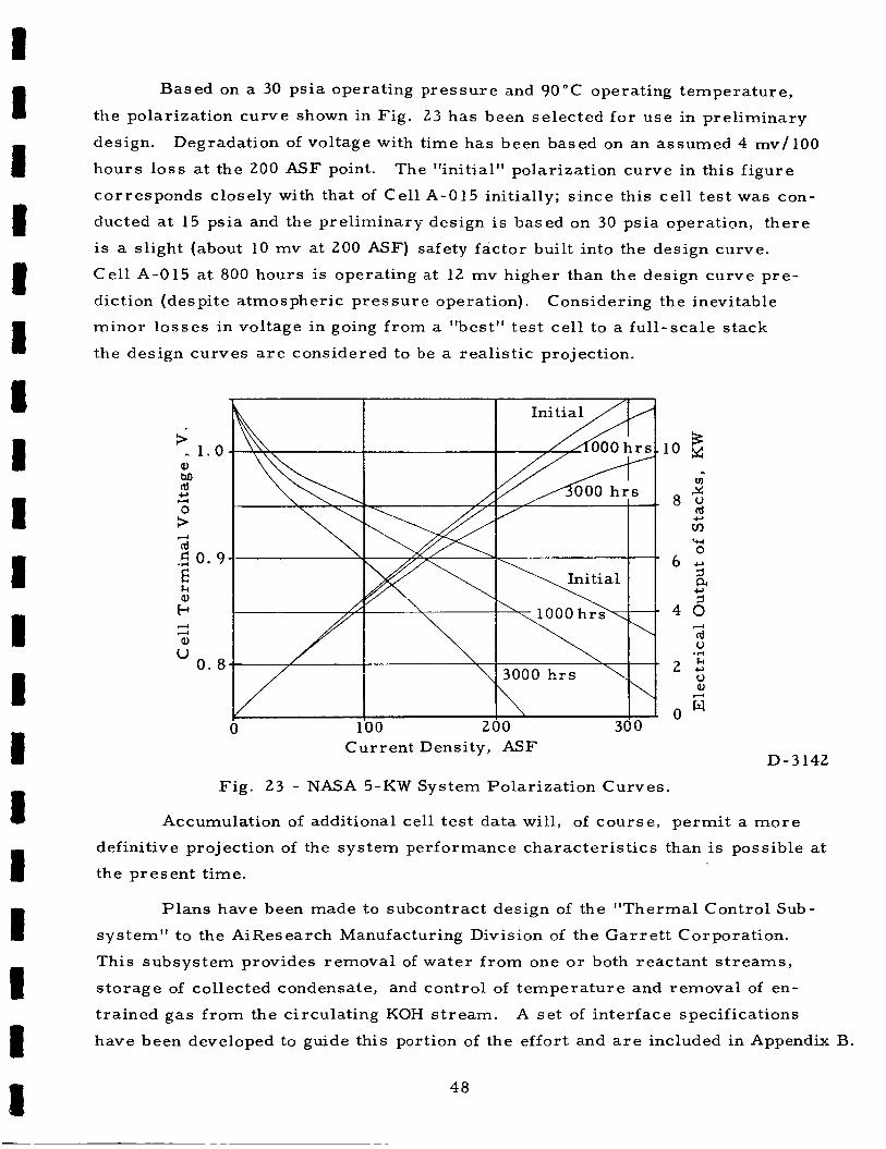
Based on a 30 psia operating p res su re and 90°C operating tempera ture ,
the polarization curve shown in Fig. 23 has been selected fo r u se in prel iminary
design.
hours lo s s at the 200 ASF point.
cor responds closely with that of C e l l A-015 initially; s ince this ce l l t e s t was con-
ducted at 15 psia and the prel iminary design i s based on 30 psia operation, t he re
is a slight (about 10 mv at 200 ASF) safety factor built into the design curve.
Ce l l A-015 at 800 hours is operating a t 12 mv higher than the design curve p re -
diction (despite a tmospheric p re s su re operation).
minor lo s ses in voltage in going f rom a "best" tes t ce l l to a ful l -scale s tack
the design curves a r e considered to be a real is t ic projection.
Degradation of voltage with time has been based on an assumed 4 mv/100
The "initial" polarization curve in this f igure
Considering the inevitable
+ II 1 . 0 a, M cd
W 0. 8
Current Density, ASF D-3142
Fig. 23 - NASA 5-KW System Polar izat ion Curves.
Accumulation of additional cell t e s t data will, of cour se , permi t a m o r e
definitive projection of the sys tem performance charac te r i s t ics than is possible at
the present time.
P lans have been made to subcontract design of the "Thermal Control Sub-
system" to the AiResearch Manufacturing Division of the G a r r e t t Corporation.
This subsystem provides removal of water f rom one o r both reactant s t r e a m s ,
s torage of collected condensate, and control of tempera ture and removal of en-
t ra ined g a s f rom the circulating KOH s t r eam. A se t of interface specifications
have been developed to guide this portion of the effort and a re included in Appendix B.
48
B .10 g
2 . 8 ;
c,
d
cd 0 .r(
Li ' 0

PLANS FOR FUTURE WORK
Effor t under the Task 1 -Electrode Improvement program will continue with
fur ther testing of small (4" x 4-1/2") cells.
to ver i fy improvements in electrode quality, uniformity, and performance resulting
f r o m changes in specifications o r fabrication techniques, and second, to collect
performance data over a broad range of operating conditions to guide the sys tem
engineering design effort.
against a routine 200 ASF life test .
t empera ture , electrolyte concentration, fluid flow ra t e s , etc. , will provide a p re -
l iminary definition of optimum design center values and tolerances on these v a r -
iables.
for the establishment of a bill-of -qualified-materials covering all of the essent ia l
ma te r i a l s of the fuel cell .
validation and refining of t e s t procedures, leading to an accumulation of data
which will provide a rational bas i s for establishing future inspection and accept-
ance t e s t procedures , and which will permit the writing of real is t ic mater ia l s
specifications.
This effort has two objectives; f i r s t ,
Improvements in electrode quality will be measured
Cell t es t s under controlled variations in
Testing of ce l l mater ia l s will be continued to collect the data required
An important by-product of this t e s t program is the
Effort under the Task 1 program will culminate in the performance testing
of "flight-size" cel ls (i. e . , one square foot of anode and cathode a r e a per cel l ) .
Design of these cel ls will b e based on data collected f r o m 4" x 4 - 1 / 2 " cel l t es t s
pius engineering calculations to establish reasonable values for geometr ic param-
e t e r s , cu r ren t collector configuration, fluid entrance and exit ports , etc.
Work has just been initiated on the Task 2-Pre l iminary System Design.
This effort will include:
1. Development of an overall system schematic and flow diagram describing
water removal and temperature control subsystems and including all fluid
and coolant flow ra t e s , and giving fluid types, t empera tures , and p r e s -
s u r e s representat ive of operation to the load profile shown in Fig. 22 .
2. Prepara t ion of an assembly drawing of the electrochemical ce l l s , includ-
ing reactant manifolding, electrolyte manifolding, and recommended
se r i e s -pa ra l l e l e lectr ical connections, to obtain a 29-volt DC s tack
capable of delivering 5 ,000 watts.
49

3 . Development of a control schematic, including identification of control
and sensing elements, variables to be controlled, mode of control, and
acceptable operating range for each system component.
4. Identification of all system components whose operation is dependent
upon, o r influenced by gravity.
5. Preparat ion of a source list f o r all i t ems to be used in assembly of
the system hardware. This list shall include:
a. Identification of components the Contractor proposes to supply.
b . Identification of those components which the Contractor anticipates
may be purchased in a form suitable to fully meet the requirements
of the environmental specification.
50

APPENDIX A
ENVIRONMENT A L SPEC IF1 C AT IONS
All environmental tests descr ibed below a r e assumed to be conducted at a t e s t
t empera tu re of 20°C.
contain fluid in normal se rv ice shal l be filled with the proper fluid to s imulate
se rv i ce conditions.
All t e s t s shall be non-operating t e s t s . Components which
1. Shock
The t e s t piece shal l be securely mounted in a t e s t f ixture specifically
designed to support the piece in each of th ree perpendicular axes for shock
testing. The t e s t piece shall remain inoperative throughout the shock tes t s
Three shock impulses of 18 g ' s shall be applied to the t e s t piece along each
of the three perpendicular axes in each direction making a total of 18 shock
impulses per cell.
fo r a t ime duration of eight milliseconds.
Each input pulse waveshape will be a half-sine pulse
2. Vibration
The test piece shal l be securely mounted i n a text f ixutre specifically
designed to support the piece ir, any cf the three m-utually perpendicular
axes fo r vibration t e s t s .
out the vibration tes t s .
The test piece shall remain inoperative through-
A resonant survey tes t will b e performed to determine the resonant modes
of the t e s t f ixture and piece.
24. 5 cps with a displacement amplitude of 0. 50 inch peak to peak f r o m
24. 5 to 3000 cps a t 15 g, z e r o t o peak.
formed once along each of the three mutually perpendicular axes .
each frequency sweep all resonant frequency points shal l be recorded.
duration of each frequency sweep in each axis shall be one minute f r o m 10
to 24. 5 cps and ten minutes f rom 24. 5 to 3000 cps. A resonant frequency
t e s t at one-half of each resonant frequency resulting f r o m the resonant
frequency sweep noted above, shall b e performed f o r a period of 30 minutes
f o r each resonant frequency.
A frequency sweep will be made f r o m 10 to
This frequency sweep shall b e pe r -
During
The
3 . Acoustic Noise
The t e s t piece shal l be securely mounted in a t e s t f ix ture specifically designed to support the piece in any of the t h r e e mutually perpendicular axes f o r the
51

acoust ic noise tes t s .
t e s t s .
no ise tests.
An acoust ic noise tes t shall be performed by applying a total integrated
sound p r e s s u r e level of 148 decibels, Re 0.0002 m i c r o ba r with a f re-
quency spec t rum as shown in F i g . 24 for a period not l e s s than five min-
utes .
dicular axes.
An acoustic noise chamber shal l be used for these
The tes t piece shal l remain inoperative throughout the acoustic
The t e s t shal l be performed in each of the three mutually perpen-
10 100 1000 10000 One-Third Octave Center Band Frequency (CPS)
D-3184
Fig. 24 - Acoustic Noise Frequency Spectrum.
4. Accelerat ion
The test piece shal l be securely mounted in a t e s t f ixture specifically
designed to support the piece in any of the th ree mutually perpendicular
axes f o r the acceleration t e s t s .
inoperative throughout the acceleration tes t s .
The test piece sha l l remain electrically
Accelerat ion tes t s shal l be performed in accordance with the following
proc edur e:
a. A sustained accelerat ion force of 18 g ' s shal l be applied fo r five
minutes along the longitudinal axis chosen in a direction simulating
the lift-off of the transporting space vehicle.
52

b. A sustained acceleration force of 18 g ' s shal l b e applied for five
minutes along the longitudinal axis in the opposite direction to
that in Item a. above.
A sustained acceleration force of 18 g ' s shall be applied for five
minutes in both directions along each of the remaining two mutually
perpendicular axes to the longitudinal axis of I tems a. and b. above
c .
5. Tolerances
The following tolerances shal l apply to all environmental t es t s unless
otherwise specified:
a.
b.
C .
d.
e.
f .
g -
Tempera ture , h 5 " F o r 370, whichever is g rea t e r
Vibration Amplitude (g o r inches), h 10%
Vibration Frequency (cps), k270 o r 1 cps, whichever is g rea t e r
Shock, (g) h l O T o
Acceleration (g), k570 a t reference point
Sound P r e s s u r e Level, Overall (db), k2 db
Sound P r e s s u r e Level, Any One Octave (db), h3 db
53

APPENDIX B
SPECIFICATION NO. DD-3A
THERMAL CONTROL SUBSYSTEM FOR NOMINAL 5000-WATT
AEROSPACE HYDROGEN-OXYGEN FUEL CELL POWER SUPPLY
1. ScoDe
2 .
This specification covers the requirements for a thermal control subsystem
to b e utilized with a nominal 5000-watt hydrogen-oxygen fuel cel l power
supply. m u s t be capable of operation in a space environment, including ze ro g.
The power supply and i ts associated thermal control sybsystem
Requi r ement s
The p r imary functions of the thermal control sybsystem a r e (1) to remove
water vapor f r o m a recirculating oxygen s t r eam; (2) to remove water vapor
f r o m a recirculating hydrogen s t r eam; (3) to s t o r e the collected condensate,
and (4) to control the temperature and remove entrained gases f rom a c i r -
culating potassium hydroxide s t ream.
subsystem must meet the requirements set forth in this specification.
While fulfilling these functions the
2. i Environnienta! Ssecifications
2. 1. 1 Zero Gravity: The thermal control subsystem shal l be operational
in a ze ro gravity environment, and each of the components shall be
operational in a 1 g environment oriented in the "neutral" attitude,
i. e. , perpendicular to that direction in which performance is
ass i s ted by gravity.
Life:
l ifetime of 3000 hours.
2 . 1 .2 The thermal control subsystem shall have an operational
2. 1. 3 Shock: The thermal control subsystem shal l not be damaged when
subjected to three shock impulses of 18 g ' s along each of the three
perpendicular axes in each direction, i. e . , a total of 18 shock
impulses .
fo r a duration of 8 milliseconds.
Each input pulse wave shape shall b e a half-sine pulse
2. 1 .4 Vibration: The thermal control subsystem shall not be damaged
by a vibrational frequency sweep f r o m 10 to 24. 5 cps with a dis-
placement amplitude of 0. 50 inch peak-to-peak f r o m 24. 5 to
3000 cps at 15 g , zero to peak. The duration of each frequency

sweep in each axis shall be one minute f rom 10 to 24. 5 cps and
10 minutes f r o m 24. 5 to 3000 cps.
withstanding frequency sweeps along any o r all of th ree mutually
perpendicular axes. In addition, the thermal control sybsystem
shal l not be damaged by a resonant frequency t e s t at one-half of
each predetermined resonant frequency for a period of 30 minutes.
System must be capable of
2. 1. 5 Acoustic Noise:
aged when subjected to a total integrated sound p r e s s u r e level of
148 decibels, Re 0. 0002 microbar with a frequency spec t rum as
shown in Fig. 24 fo r a period not less than five minutes. This
sound p r e s s u r e can be applied along each of the th ree mutually
perpendicular axes.
The thermal control subsystem shal l not be dam-
2. 1 .6 Operating Temperature: The thermal control subsystem shal l b e
operational in ambient tempera tures f r o m +35 to 160°F.
2. 1.7 Acceleration: The thermal control subsystem shall not be dam-
aged when subjected to the following acceleration test:
(a) A sustained acceleration fo rce of 18 g ' s applied for five
minutes along the longitudinal axis chosen in a direction
simuiating the lift-off of the transporting space vehicle.
A sustained acceleration fo rce of 18 g ' s applied for five
minutes along the longitudinal axis in the opposite d i rec-
tion to that in item (a) above.
A sustained acceleration fo rce of 18 g ' s applied for five
minutes in both directions along each of the remaining two
mutually perpendicular axes to the longitudinal axes of
i tems (a) and (b) above.
(b)
(c)
2. 2 Equipment
The thermal control subsystem shall include the following components:
(a) A potassium hydroxide-to-water pr imary heat exchanger.
(b) A means of controlling the water flow r a t e through the potassium hydroxide heat exchanger.
A condenser fo r removing water vapor f r o m a recirculating hydrogen
s t r eam.
(d) A condenser fo r removing water vapor f r o m a recirculating oxygen s t ream.
(c)
55

(e) Tankage for collecting condensate.
(f ) A gas -liquid separa tor fo r the circulating potassium hydroxide
system.
(g) Any controls, p r e s s u r e regulators o r auxiliary equipment neces-
s a r y for operation of i tems (a)-(f).
Although the thermal control subsystem has been defined as an integral
unit, in o rde r to permi t maximum integration of the complete power
supply, the subcontractor shall not b e responsible for the design and layout of the interconnecting piping between any of the components.
However, as s e t for th in the contract statement of work the subcontractor
must supply a fluid schematic showing how the individual components
must be coupled together to meet the operational and environmental
r equi r ements . 2 . 3 ODerational and Interface Data
The thermal control sybsystem will be supplied with a maximum of 500
l b / h r of water for u se a s a coolant. The inlet t empera ture of the water
s t r e a m will be 7 5 ° F maximum a t a total p r e s s u r e of 20 psia. The sum
of the coolant p r e s s u r e losses through all of the components in the ther -
mal control subsystem (exclusive of the interconnecting piping) shal l
b e 4. 5 psi.
l h e subcontractor is responsible for determining the optimum intercon-
nection scheme for the coolant sys tem, i. e . , heat exchanger coolant
flow in s e r i e s o r in parallel , etc.
2 . 3. 1 KOH Heat Exchanger:
the following requirements:
Maximum Heat Load
This exchanger shall b e designed to meet
22, 500 Btu /hr minus (sensible heat removed f r o m the gas s t r e a m s by the condensers whose performance i s specified in paragraphs 2. 3 . 2 and 2 . 3 . 3
KOH Flow Rate
KOH Normality 9-12 Normal
KOH Inlet P r e s s u r e (total)
KOH Inlet Temperature 194°F k5"F
KOH Outlet Temperature 184" i 5 " F
Maximum Permiss ib le 0. 85 psia P r e s s u r e Drop (KOHSide)
3 3 1 0 l b / h r (based on 11 N)
3 0 psia
56

(The fuel cel l power supply will operate over a varying load
profile. Consequently, the required hea t rejection r a t e for the
KOH heat exchanger w i l l vary. The data shown in para . 2. 3. 1 a r e representat ive of the peak duty.
to influence the design, the duty cycle fo r the heat exchanger
over all operating conditions will b e issued a s a supplement to
this specification within 15 days af ter the subcontractor init iates
work. )
Although it is not expected
2. 3. 1. 1 Electr ical Potential:
designed so a s not to be influenced by an electr ical c u r -
rent of 2 amps which the circulating potassium hydroxide
s t r e a m will be carrying.
The KOH heat exchanger shall b e
A meta l KOH hea t exchanger will c a r r y a DC. potential
because of this contact with the fuel cell electrolyte.
The value of this D C . voltage is a function of the sys tem
design and may b e a t any value between 0-36 volts,
depending on choices of heat exchanger placement, fuel
ce l l electrolyte feed and discharge design, etc.
2. 3.2 Hydrogen Sybsystem Condenser: The hydroger, sybsystem conden-
s e r shall b e designed to mee t the following requirements:
Hydrogen Inlet Temperature 194°F
Hydrogen Fiow Rate ( a s Dry Gas) 4.34 !b/hr
Inlet H20 Partial P r e s s u r e
Hydrogen Str eam Inlet P r e s s u r e (Total) H 2 0 Condensation Rate 3.27 lb /h r
Hydrogen Side A P
160 mm Hg
28. 5 psia
0. 5" water max.
(As noted for the KOH hea t exchanger, the hydrogen condenser
duty cycle will v a r y as the load profile on the fuel ce l l is var ied.
The data shown in para. 2. 3. 2 a r e representat ive of the average
condensation point. Within 15 days af ter the subcontractor init iates
work, a supplement to this specification will be i ssued showing con-
ditions for all operating points. )
2. 3 . 3 Oxygen Subsystem Condenser: The oxygen subsystem condenser
shal l be designed to meet the following requirements:
-57.

I 1 1 I
2 . 3 . 4
2. 3 .5 I I I I I
Oxygen Inlet Temperature 194°F
Oxygen Flow Rate ( a s Dry Gas)
Inlet H2O Partial P r e s s u r e
Oxygen S t r eam Inlet P r e s s u r e (Total)
H20 Condensation Rate 1 .09 l b / h r
Oxygen Side AP 0. 5" water max.
32.07 lb /h r
120 mm Hg
28. 5 psia
(As with the hydrogen subsystem condenser, the data shown in
para . 2. 3. 2 a r e representative of the maximum condensation
point.
plement to this specification will be issued showing conditions
for all operating points. )
Within 15 days af ter subcontractor initiates work a sup-
Condensate Tankage:
s torage of 56 lb of water.
ually dumping excess water when the 56-lb point is exceeded.
A gauging sys tem shall b e included which will provide the oper-
a tor with a signal so that he knows when to dump.
This tankage shal l be sized to provide
A means shall b e provided for man-
Gas -Liquid Separator: The pr imary function of the gas -liquid
separa tor is to remove entrained oxygen o r hydrogen f r o m the
circulating potassium hydroxide s t r eam.
incorporated to automatically vent the collected gas to the
ambient whether it be at space vacuum o r 14 psia.
may be hydrogen o r oxygen o r mixtures of the two.
of the gas-liquid separator shall consider the explosive nature
of such mixtures and provisions incorporated to minimize the
resultant hazards .
to meet the following requirements:
A means shal l b e
The gas
The design
The gas -liquid separa tor shal l be designed
KOH (as Liquid) Flow Rate*
KOH Normality 9-12 Normal
KOH Temperature (Maximum) 199°F
Max. Pe rmis s ib l e P r e s s u r e Drop
Estimated Entrained Gas Content (Max. Entering Separator)
3310 lb /h r
0 .65 psi
60 cc /min
* The design shal l consider the fac t that this KOH can contain carbon par t ic les ranging in s i ze up to 30 microns.

I I I
I I I I I I I
I I
Estimated Size Range of Gas Bubbles (Entering S eparator)
Allowable Entrained G a s Con- tent (Leaving Separator)
0. 027" - 0. 200" diam.
0. 50 cc /min .
During venting of the collected gases , loss of small quantities
of KOH can be tolerated. Such losses shal l not exceed 625 ml
for every 1500 hours of operation.
2. 3 . 6 Controls, P r e s s u r e Regulators and/or Auxiliary Equipment: The
thermal control subsystem shall incorporate the necessary con-
t ro l s , instrumentation and/or auxiliary equipment needed to sense
the KOH outlet temperature f rom the pr imary heat exchanger and
to control it within the range of 179°F to 189"F, e. g . , an auto-
mat ic valve on the water supply to the heat exchanger.
2. 3 .6 . 1 Power for Auxiliaries:
available for energizing subsystem auxiliaries. DC power
will be at a potential of 29 ~2 volts while the AC will be
three phase 11 5 *5 volts (line to neutral) at 400 cycles per
second. The ult imate selection of which type power is
used should b e made on the bas i s of obtaining the most
reliable and/or qualified components.
Ei ther DC o r AC power will be
2. 3 . 6 . 2 P r e s s u r e References: Two al ternate types of p r e s s u r e
re ference schemes for the overal l fuel ce l l sys tem will
b e investigated by Union Carbide Corporation.
1.
These a r e :
U s e of individual absolute p r e s s u r e re ference s tandards
on each p r e s s u r e regulation device, and
Placing the ent i re sys tem in a capsule which is main-
tained at an ambient p r e s s u r e of 14 psia * O . 25 psia.
2 .
(Within thirty days after initiating work subcontractor should advise
Union Carbide Corporation of the advantages o r disadvantages of
either scheme a s far a s the the rma l control subsystem is concerned. )
2. 4 General Information
2 . 4 . 1 KOH in Gas Streams:
cor rode in the presence of potassium hydroxide, the design of the
the rma l control subsystem should a s s u m e that t he re is no potassium
hydroxide ca r r i ed in the circulating hydrogen or oxygen s t r eams .
Except f o r avoiding materials which rapidly
59

I I I I I I I I ID I I I I I I I I I I
2 . 4 . 2
2 . 4 . 3
2 . 4 . 4
2 . 4 . 5
However, the thermal control subsystem design repor t submitted
to Union Carbide Corporation shall include a discussion of the
consequences of a malfunction which would permit 20 m l / h r of
12 N KOH to be released into either o r both of the circulating
gas s t r eams .
Mater ia ls
2.4. 2. 1 Exposed to KOH: All mater ia l s which will be exposed to
the circulating KOH s t r e a m mus t be res i s tan t to cor ros ion
and nonpoisoning to the fuel ce l l system.
mater ia l s which f i t these c r i t e r i a are: nickel, most plas-
t i cs , precious meta l brazing alloys, sulfur-free ethylene
propylene, and sulfur-free neoprene.
Acceptable
Obviously, the subcontractor cannot determine which
mater ia l s a r e nonpoisoning to the fuel ce l l system.
fore , the subcontractor shal l submit to Union Carbide a
list of all mater ia l s (including their chemical analysis , i f
alloys) which will be exposed to KOH in the thermal control
subsystem.
ch i l l be m-ade until writ ten approval of the mater ia l s is
received.
approval o r disapproval within 24 hours af ter receipt of
a request.
The re -
N o weight es t imates o r strength calculations
Union Carbide Corporation will w i re such
2. 4. 2. 2 Gas and Condensate System:
i a l which corrodes rapidly in the presence of KOH shal l b e
used in the gas , condensate o r coolant sys tems. Magnes-
ium, nickel, plast ics , s ta inless s teel , etc. a r e typical
acceptable mater ia l s fo r these sys tems.
No aluminum o r other m a t e r -
Design Considerations:
t ro l subsystem shall be designed to obtain the minimum weight and
volume configuration consistent with the environmental and opera-
tional specifications s e t forth in this specification.
Each of the components of the thermal con-
Proper t ies of KOH: In all design calculations the physical p roper -
t ies of KOH supplied by Union Carbide Corporation should be used.
Overall System Schematic :
the overall sys tem schematic fo r reference.
Union Carbide Corporation will supply
6 0

1 I i I 6 1 1
I I M I 1 1 I I
2 . 4 . 6 Mounting Brackets: Mounting brackets and/or shock abso rbe r s , i f
required, shal l be included in the design of each of the components
in the thermal control subsystem.
Carbide Corporation shall coordinate this portion of the design s o
that the components w i l l mount into the overal l sys tem.
The subcontractor and Union
2.4. 7 Interconnecting Line Sizes: Within 1 5 days af ter the subcontractor
initiates work, Union Carbide Corporation will advise h im of the
interconnecting line s izes fo r the H2, 0 2 , and KOH s t r eams .
Within the same time period the subcontractor shall recommend
line s izes for the coolant s t r eams . Each of the thermal control
subsystem components shal l include connections which will permit
removal of the component f rom the system.
2. 4. 8 Reliability: Although formal reliability analysis of the thermal con-
t ro l subsystem i s - not required under the present contract , the de-
sign should consider that ultimately such work will be required with
the goal of space qualifying (for unmanned missions only) the r e -
sultant hardware.
2.4. 9 Instrumentation: The Jesign, e. g. , source list, drawings, etc. , of the thermai control subsystem sha11 not include aay inst rumenta-
tion whose sole purpose is to provide te lemetry signals which could
be used to monitor performance of the subsystem during a mission.
However, in the final thermal control subsystem design repor t
submitted to Union Carbide Corporation the subcontractor shall
include a l i s t of recommended pa rame te r s which should be moni-
tored in order to permit malfunction analysis during a mission.
61

DISTRIBUTION LIST NAS3-9430
National Aeronautics & Space Administration Washington, D. C. 20546 Attention: E r n s t M. Cohn, Code RNW
G. F. Esenwein, Code M-4T A. M. Greg Andrus, Code F C T. Albert, Code MLT Office of Technology Utilization
National Aeronautics & Space Administration S c i entif i c and T ec hnic a1 Information Facil i ty P o s t Office Box 33 College Pa rk , Maryland 20740 Attention: NASA Repr e s entativ e
National Aeronautics & Space Administration Goddard Space Flight Center Greenbelt, Maryland 20771 Attention: Thomas Hennigan, Code 7 16. 2
National Aeronautics & Space Administration Langley Research Center - Langley Station Hampton, Virginia 23365 Attention: John Pat ter son
National Aeronautics & Space Administration Lewis Research C enter 2 1000 Brookpark Road Cleveland, Ohio 44135 Attention: B. LuSarsky, Mail Stop 500-20 1
M. J. Saar i , Mail Stop 500-202 H. J. Schwartz, Mail Stop 500-202 J. E. Dilley, Mail Stop 500-309 N. D. Sanders, Mail Stop 302-1 J. S. Fordyce, Mail Stop 302-1 R. R. Miller, Mail Stop 500-202
No. Copies
2 + 1 reproducible
1
1
Technology Utilization Office , Mail Stop 3 - 19 W . A. Robertson, Mail Stop 500-202 2
Library , Mail Stop 60-3 1 J . M. McKee, Mail Stop 500-202 1 Report Control, Mail Stop 5-5 1
1
V . Hlavin, Mail Stop 3-14 (Final only) 1
National Aeronautics & Space Administration George C. Marshall Space Flight Center Huntsville, Alabama 3 5 8 12 Attention: Mr . Charles Graff, R-ASTR-EAP
Mr . Richard Boehme, R-ASTR-E
National Aeronautics & Space Administration Ames Research Center - Pioneer P ro jec t Moffett Field, Mountain View, Calif. 94035 Attention: John Rubenz e r
1 1
1

2 I I
I 1 I
n
1 1 1 I I I 1 I I
DISTRIBUTION LIST NAS3-9430
No. Copies
National Aeronautics and Space Administration Manned Spacecraft Center Houston, Texas 77001 Attention: William R. Dus enbury
F. E. Eastman (EE-4) Hoyt McBryar (EP-5, Bldg. 16)
J e t Propulsion Laboratory 4800 Oak Grove Drive Pasadena, California 91103 Attention: Aiji Uchiyama
National Aeronautics and Space Administration Electronics Research Center 575 Technology Square Cambridge, Massachusetts 02139 Attention: D r . S. Gilman
Department of the Army
U. S. Army Engineer R & D Laborator ies F o r t Belvoir, Virginia 22060 Attention: Energy Conversion Research Lab
C oniniandiiig Genera! U. S. Army Electronics Command Power Sources Branch F o r t Monmouth, New J e r s e y 07703 Attention: Code AMSEL-KL-P
H a r r y Diamond Laboratories Room 300, Building 92 Connecticut & Van Ness , N . W Washington, D, C . 20438 Attention: Nathan Kaplan
U. S. Army Natick Laborator ies Clothing & Organic Mater ia ls Division Natick, Massachusetts 0 1760 Attention: Leo A. Spano
Department of the Navy
Office of Naval Research Department of the Navy Washington, D. C . 20360 Attention: D r . Ralph Roberts /H. W. Fox
U. S. Naval Research Laboratory Washington, D. C . 20390 Attention: Dr . J. C . White, Code 6160
1
1
1
1
1
1

3 DISTRIBUTION LIST NAS3-9430
No. Copies
C ommander , Naval Ship Sys t ems Command Department of the Navy Washington, D. C. 20360 Attention: B. B. Rosenbaum, Code 03422
Commander, Naval Ship Systems Command Department of the Navy Naval Ship Engineering Center Washington, D. C. 20360 Attention: C. F. Viglotti, Code 6157
Naval Ordnance Laboratory Department of the Navy Corona, California 91720 Attention: William C . Spindler, Code 441
Naval Ordnance Laboratory Department of the Navy Si lver Spring, Maryland 20910 Attention: Phill ip B. Cole, Code 232
U. S. Navy Marine Engineering Lab Special Pro jec ts Division Annapolis, Maryland 2 1402 Attention: J. H. Harrison
Department of the Air F o r c e
Aeronautical Sys tems Division Flight Vehicle Power Branch Air F o r c e Aero Propulsion Laboratory Wright-Patterson Air F o r c e Base , Ohio 45433 Attention: J. E. Cooper, Code APIP-2
Air F o r c e Cambridge Research Laboratory L . G. Hanscom Field - CRE Bedford, Massachusetts 01731 Attention: F. X. Doherty
E . Raskind (Wing F)
Rome Air Development Center Griffiss AFB, New York 13442 Attention: F r a n k J. Mollura (RASSM)
Other Government Agencies
Army Reactors , DRD U. S. Atomic Energy Commission Washington, D. C. 20545 Attention: D. B. Hoatson
1
1
1
3
1
1
1 1
1
1

4
DISTRIBUTION LIST NAS3-9430
I 1 I I I I I I
Office, DDR&E: Sea Warfare Systems The Pentagon Washington, D. C. 20301 Attention: G. B. Wareham
Office of Technical Services Department of Commerce Washington, D. C. 20009
Clearing House 5285 P a r k Royal Road Springfield, Virginia 22 15 1
Bureau of Mines 4800 Forbes Avenue Pittsburgh, Pennsylvania 152 13 Attention: Mr . D. Bienstock
P r iv at e Industry
A e r onu t r onic Div is ion Phi lco Corporation - F o r d Road Newport Beach, California 92663 Attention: Technical Information Serv ices
AiRes earch Manufacturing Company 9851 Sepulveda Blvd. Los Angeles, California 90009 Attention: Mr . D. S. Davis
Allis -Chalmers Manufacturing Company 1100 South 70th Street Milwaukee, Wisconsin 532 14 Attention: J. W. McNeil, Manager
Marketing Research Division
Allis -Chalmers Manufacturing Company Re s e a r c h Div i s i on P. 0. Box 512 Milwaukee, Wisconsin 5320 1 Attention: Dr . P. A. Joyner
Allison Division General Motors Corporation Indianapolis, Indiana 46206 Attention: Dr. Robert E. Henderson
American Machine & Foundry Research & Development Division 689 Hope St ree t Springdale, Connecticut 06879 Attention: Dr . L. H. Shaffer
No. Copies
1
1
1
1
1

5 DISTRIBUTION LIST NAS3-9430
American Cyanamid Company 1937 West Main Street Stamford, Connecticut 0690 1 Attention: Dr. R. G. Haldeman
Aerospace Corporation P. 0. Box 95085 Los Angeles, California 90045 Attention: Technical L ib ra ry Acquisitions Group
Arthur D. Litt le Incorporated Acorn P a r k Cambridge, Massachusetts 02 140 Attention: Dr . El lery W. Stone
Atlantic Refining Company 500 South Ridgeway Avenue Glenolden, Pennsylvania 19036 Attention: Dr . Harold Shalit
Atomics International Division North Am e r ic an Aviation Incorporated 8900 DeSoto Avenue C anoga P a r k , California 9 1304 Attention: Dr . H. L. Recht
B at t e 11 e M em0 r ia l Ins ti tut e 505 King Avenue Columbus, Ohio 43201 Attention: Dr . C . L Faus t
Bell Telephone Laboratories Incorporated Murray Hill, New J e r s e y 07971 Attention: M r . U. B. Thomas
ChemC el l Incorporated 150 Dey Road Wayne, New Jersey 07470 Attention: M r . Pe te r D. Richman
Clevite Corporation Mechanical Research Division 540 East 105 Street Cleveland, Ohio 44108 Attention: D. J. Berger
Dynatech Corporation 17 Tudor S t ree t Cambridge, Massachusetts 02139 Attention: R. L. Wentworth
No. Copies
1
1
1
1
1
1
1
1
1
1

6 DISTRIBUTION LIST NAS3-9430
No. Copies
Douglas Aircraf t Company, Inc. As t r opow e r Lab0 r ator y 2121 Campus Drive Newport Beach, California 92663 Attention: Dr. C a r l Be rge r
Elect rochimica C orpor ation 1140 O'Brien Drive Menlo P a r k , California 94025 Attention: Dr. Morr is Eisenberg
Electro- Optical Sys tems , Inca 300 North Halstead S t r ee t Pasadena, California 91 107 Attention: Mr . Kline
Engelhard Industries, Inc. 497 Delancy St ree t Newark, New Jersey 07105 Attention: Dr. J. G. Cohn
Esso Research and Engineering Company Government Division P. 0. Box 8 Linden, New Je r sey 07036 Attention: Dr. C . E. Heath
The Frankl in Institute Benjamin Franklin Parkway Philadelphia, Pennsylvania 19 103 Attention: Robert Goodman
G a r r e t t Corporation 1625 Eye St ree t , N. W. Washington, D. C. 20013 Attention: Mr . Bowler
1
1
General Dynamic s /C onvair P. 0. Box 1128 San Diego, California 92 112 Attention: R. P. Mikkelson, 1
Electr ical Systems Department 988-7
General Electr ic Company Direct Energy Conversion Operations 930 Western Avenue Lynn, Massachusetts 0 190 1 Attention: P. Schrat ter
General Electr ic Company Research & Development Center P. 0. Box 8 Schenectady, New York 1230 1 Attention: Dr. H. Liebhafsky

7
DISTRIBUTION LIST NAS3-9430
No. C opie s
General Electr ic Company 777 - 14th S t ree t , N . W. Washington, D. C. 20005 Attention: P. C. Hargraves
General Motors Corporation P. 0. Box T Santa Barba ra , California 93 102 Attention: Dr . C . R. Russell
G ene r a1 Mo to r s Corporation Res ea r c h Labor a t o r ies Electrochemistry D epar tment 12 Mile & Mound Roads Warren, Michigan 48090 Attention: D r . S. E. Beacom
Glob e -Union Incorporated P. 0. Box591 Milwaukee, Wisconsin 5320 1 Attention: J. D. Onderdonk
Hugh e s Res e a r ch Lab0 rat0 r i e s Corpora tion 30 11 ?da!ibu Canyon Road Malibu, California 90265 Attention: T. M. Hahn
Ionic s Incorporated 65 Grove S t r ee t Watertown, Massachusetts 02 172 Attention: Dr . Werner Glass
Institute fo r Defense Analyses Research & Engineering Support Division 400 Army-Navy Drive Arlington, Virginia 22202 Attention: D r . G. C . Szego
Dr . R. Briceland
Institute of Gas Technology State and 34th Streets Chicago, Illinois 606 16 Attention: Dr. B. S. Baker
Johns Hopkins University Applied Physic s Labor at o r y 8621 Georgia Avenue Si lver Spring, Maryland 20910 Attention: R. Cole
1
1
1
1
1
1
1 1
1
1

DISTRIBUTION LIST NAS3-9430
8
No. Copies
I 1 1 I I 1
Johns -Manville R&E Center P. 0. Box 159 Manville, New Je r sey 08835 Attention: 3. S. Parkinson
Leesona Moos Laborator ies Lake Success P a r k Community Drive Grea t Neck, New York 11021 Attention: D r . A. Moos
Lockheed Missi les and Space Company Technical Information Center 3251 Hanover Street Pa lo Alto, California 93404
McDonnell Air c raft C o r poration P. 0. Box 516 St. Louis, Missouri 63166 Attention: P ro jec t Gemini Office
Midwest Res ear ch Ins ti tut e 4 2 5 Volker Boulevard Kansas City, Missouri 641 10 Attenti on: Physic a1 S c i enc e Library
Monsanto Research Corporation Boston Laboratories Everet t , Massachusetts 02149 Attention: Dr . J. 0. Smith
Monsanto Research Corporation Dayton Laboratory Dayton, Ohio 45407 Attention: Lib r ar ian
North American Aviation Company S&ID Division Downey, California 90241 Attention: Dr . James Nash
Oklahoma State University Sti l lwater, Oklahoma 74075 Attention: Prof . William L. Hughes
Power Information Center University of Pennsylvania Moore School Building 200 South 3 3 r d Street Philadelphia, Pennsylvania 19 104
1
1
1
1
1
1
1
1
9 DISTRIBUTION LIST NAS3-9430
No. Copies
P r a t t & Whitney Aircraft Division United Air c raf t C or po r ati on East Hartford, Connecticut 06 108 Att enii on: Lib ra r ian
Radio Corporation of Amer ica Astro Division P. 0. Box 800 Hightstown, New Je r sey 08520 Attention: Dr. Seymour Winkler
Rocket dyn e 6633 Canoga Avenue Canoga P a r k , California 91304 Attention: Library , Dept. 086-306 Zone 2
Speer Carbon Company Research & Development Laborator ies Packard Road at 47th S t r ee t Niagara Fa l l s , New York 14304 Attention: W. E. P a r k e r
Stanford Research Institute 820 Mission St ree t South Pasadena, California 91 108 Attention: D r . F r i t z Kalhammer
T exa s Instruments Incorporated 13500 North Central Expres sway Dal las , Texas 75222 Attention: Dr . Is sac Trachtenberg
Thiokol Chemical Corporation Reaction Motors Division Denville, New Je r sey 07834 Attention: Dr . D. J. Mann
TRW Incorporated 23555 Euclid Avenue Cleveland, Ohio 44 117 Attention: Dr. .R. ' A. Wynveen
TRW Systems One - Space Park Redono Beach, California 90278 Attention: Dr. A. Krausz
Tyco Lab0 rat0 ri es Incorporated Bea r Hill - Hickory Drive Waltham, Massachusetts 02 154 Attention: Dr . A. C. Makrides
1
1
1
1
1
1
1
1

I I I I I 1 I I I R I I I I I 1 I I I
DISTRIBUTION LIST NAS3-9430
Unified Science Associates, Inc 826 South Arroyo Parkway Pasadena, California 9 1105 Attention: Dr . S. Naiditch
University of California Space Science Laboratory Berkeley, California 9470 1 Attention: Prof . Charles W. Tobias
University of Pennsylvania Electrochemistry Laboratory Philadelphia, Pennsylvania 19 104 Attention: Prof . John O'M. Bockris
Univ e r s i ty of P enns y lv ania Institute fo r Direct Energy Conversion 260 Towne Building Philadelphia, Pennsylvania 19 104 Attention: Dr. Manfred Altman
University of Toledo Toledo, Ohio 43606 Attention: Dr. A. Krohn
The Western Company RCA Building - Suite 802 Washington, D. C. 20006 Attention: R. T. F iske
W es t e rn Re s e rv e Univ e r s ity Department of Chemistry Cleveland, Ohio 44106 Attention: Prof. E rnes t Yeager.
We s tinghous e Electr ic Corporation Research and Development Center Chur chil l Borough Pittsburgh, Pennsylvania 1 52 3 5 Attention: Dr. A. Langer
Whittaker Corporation NARMCO R&D Division 3540 Aero Court San Diego, California 92123 Attention: Dr . M. Shaw
10
No. Copies
1
1
1
1
1
1
1
1
1

I I I I I 1 I 1 I I I I I 1 I I I I I
1 1
DISTRIBUTION LIST NAS3-9430
Yardney Elec t r ic Corporation 40 Leonard S t r ee t New York, New York 10013 Attention: Dr . George Dalin
Zaromb Research Corporation 376 Monroe S t r ee t Passaic, New York 07055
No. Copies