Object-Oriented Finite Element Analysis of Metal...
8
J. Software Engineering & Applications, 2010, 3, 572-579 doi:10.4236/jsea.2010.36066 Published Online June 2010 (http://www.SciRP.org/journal/jsea) Copyright © 2010 SciRes. JSEA Object-Oriented Finite Element Analysis of Metal Working Processes Surendra Kumar CSIR Centre for Mathematical Modelling and Computer Simulation, Council of Scientific and Industrial Research, Bangalore, India. Email: [email protected] Received March 10 th , 2010; revised March 30 th , 2010; accepted April 2 nd , 2010. ABSTRACT Recently an object-oriented approach has been applied in the fields of finite element analysis with a view to treating the various complexities within these. It has been demonstrated that finite element software designed using an object-oriented approach can be significantly more robust than traditional codes. This paper describes a special kind of implementation of object-oriented programming which is rather hybrid in nature, in the development of a finite element code for engineering analysis of metal working problems using C++, and discusses the advantages of this approach. Keywords: Finite Element Method, Data Abstraction Techniques, Object-Oriented Programming, C++ Programming Language, Metal Working 1. Introduction The finite element method (FEM) has been developed and applied extensively in various fields of engineering. It is a purely computer-oriented numerical tool and requires an extensive amount of programming effort. Major con- cerns in the development of FEM systems are placed on the computational efficiency of numerical algorithms. Traditionally, procedure oriented programming techni- ques have been widely used and procedural programming languages such as FORTRAN have been strongly sup- ported. Although the procedural approach has been proven effective in treating algorithmic complexity, this approach has intricate control strategies and internal data representation and does not address design and quality issues of the overall program. As a result, software de- veloped using this approach is likely to face difficulties in its maintenance and extensions. Recently, several investigations have been performed in applying the concept of object-oriented (O-O) meth- odology in the field of FEM [1-13]. It has been verified that object-oriented programming can provide strong support to desirable features of FEM systems such as reusability, extensibility, easy maintenance, etc. These benefits are achieved by well defined mechanisms of modular design and reusability of code. The object-orient- ed approach attempts to manage the complexity inherent in real-world problems by abstracting out knowledge and encapsulating it within objects. The various features of this approach consist of a class mechanism with inheri- tance and virtual function call mechanism, in addition to the facilities supporting data abstraction techniques and polymorphism. A detailed account of object-oriented pro- gramming can be found in several computer journals, language user guides and other literatures [14-16]. Mackerle [17] presents a list of published papers deal- ing with object-oriented programming (OOP) applied to FEM and BEM. In one of earlier investigations, Zimmer- mann et al. [2] discussed the concept of OOP as applied to the implementation of the finite element method. Huang et al. [4] have proposed a knowledge base system in which an object-oriented analysis in the FEM domain is carried out by means of introducing entity analysis concepts. Zimmermann et al. [5] discussed the key features of an integrated environment of finite element related technique which includes an object-oriented graphic interactive environment and object-oriented operators for symbolic mathematical derivations. Archer et al. [6] demonstrated an object-oriented architecture for finite element analysis based on a flexible and extendible set of objects that fa- cilitate finite element modeling and analysis. Yu and Kumar [7] presented an object-oriented framework for implementing finite element method and explored ways to exploit the commonalities between various types of ele- ments, loads, constraints and solvers so that duplication is reduced and software reuse is improved. Mackie [8] de- scribed a study into the object-oriented implementation of distributed finite element analysis on desktop computers
Transcript of Object-Oriented Finite Element Analysis of Metal...

J. Software Engineering & Applications, 2010, 3, 572-579 doi:10.4236/jsea.2010.36066 Published Online June 2010 (http://www.SciRP.org/journal/jsea)
Copyright © 2010 SciRes. JSEA
Object-Oriented Finite Element Analysis of Metal Working Processes
Surendra Kumar
CSIR Centre for Mathematical Modelling and Computer Simulation, Council of Scientific and Industrial Research, Bangalore, India. Email: [email protected] Received March 10th, 2010; revised March 30th, 2010; accepted April 2nd, 2010.
ABSTRACT
Recently an object-oriented approach has been applied in the fields of finite element analysis with a view to treating the various complexities within these. It has been demonstrated that finite element software designed using an object-oriented approach can be significantly more robust than traditional codes. This paper describes a special kind of implementation of object-oriented programming which is rather hybrid in nature, in the development of a finite element code for engineering analysis of metal working problems using C++, and discusses the advantages of this approach. Keywords: Finite Element Method, Data Abstraction Techniques, Object-Oriented Programming, C++ Programming
Language, Metal Working
1. Introduction
The finite element method (FEM) has been developed and applied extensively in various fields of engineering. It is a purely computer-oriented numerical tool and requires an extensive amount of programming effort. Major con-cerns in the development of FEM systems are placed on the computational efficiency of numerical algorithms. Traditionally, procedure oriented programming techni- ques have been widely used and procedural programming languages such as FORTRAN have been strongly sup-ported. Although the procedural approach has been proven effective in treating algorithmic complexity, this approach has intricate control strategies and internal data representation and does not address design and quality issues of the overall program. As a result, software de-veloped using this approach is likely to face difficulties in its maintenance and extensions.
Recently, several investigations have been performed in applying the concept of object-oriented (O-O) meth-odology in the field of FEM [1-13]. It has been verified that object-oriented programming can provide strong support to desirable features of FEM systems such as reusability, extensibility, easy maintenance, etc. These benefits are achieved by well defined mechanisms of modular design and reusability of code. The object-orient- ed approach attempts to manage the complexity inherent in real-world problems by abstracting out knowledge and encapsulating it within objects. The various features of
this approach consist of a class mechanism with inheri-tance and virtual function call mechanism, in addition to the facilities supporting data abstraction techniques and polymorphism. A detailed account of object-oriented pro- gramming can be found in several computer journals, language user guides and other literatures [14-16].
Mackerle [17] presents a list of published papers deal-ing with object-oriented programming (OOP) applied to FEM and BEM. In one of earlier investigations, Zimmer- mann et al. [2] discussed the concept of OOP as applied to the implementation of the finite element method. Huang et al. [4] have proposed a knowledge base system in which an object-oriented analysis in the FEM domain is carried out by means of introducing entity analysis concepts. Zimmermann et al. [5] discussed the key features of an integrated environment of finite element related technique which includes an object-oriented graphic interactive environment and object-oriented operators for symbolic mathematical derivations. Archer et al. [6] demonstrated an object-oriented architecture for finite element analysis based on a flexible and extendible set of objects that fa-cilitate finite element modeling and analysis. Yu and Kumar [7] presented an object-oriented framework for implementing finite element method and explored ways to exploit the commonalities between various types of ele-ments, loads, constraints and solvers so that duplication is reduced and software reuse is improved. Mackie [8] de-scribed a study into the object-oriented implementation of distributed finite element analysis on desktop computers
Object-Oriented Finite Element Analysis of Metal Working Processes 573
using the .NET framework. Heng and Mackie [9] pro-posed the use of software design patterns to capture best practices in O-O finite element programming.
Some research papers discuss the object-oriented tech-niques in the context of specific problems and also depict changes in the overall design or specific aspects in the design. Tabatabai [10] suggested an O-O finite element environment for reinforcement dimensioning of two- and three-dimensional concrete panel structures. Pantale [11] presented benefits of using an OOP approach in com-parison with traditional programming language ap-proaches in the analysis of inelastic deformations and impact processes. Kromer et al. [12] described an ap-proach to the design and implementation of a multibody systems analysis code using an object-oriented architec-ture. Franco et al. [13] discussed the aspects of the OOP used to develop a Finite Element technique for limit analysis of axisymmetrical pressure vessels.
Although, the basic concepts of the design of an O-O finite element program are same, varying degrees of ob-ject orientation – even procedural design – can be ac-complished using an O-O language depending upon a variety of factors including the software requirements, language features, executing environment and developer’s methodology and viewpoint. Furthermore, one of the important challenges in developing O-O finite element codes is to find the balance between good abstractions and high computational efficiency, since the data abstraction and the associated polymorphism results in loss of nu-merical performance because it requires late (dynamic) binding. Compiler optimization and flow of execution in a process (computer program) are also more amenable to procedure-oriented code. Inspite of tremendous advan- cements in computer hardware capability, the numerical efficiency of finite element codes remains an important factor since demand for non-linearities, mesh refinement, coupled analysis and other complexities in the finite element solution are also growing. Unfortunately in early investigations, O-O philosophy has been considered as a systematic obligation and even numerical tools such as Gauss integration schemes have been abstracted out as objects. It is obvious that this extreme inclination towards data abstraction for each conceptual entity can lead to a serious loss of performance and difficulty in maintenance.
In the present investigation, a particular kind of ob-ject-oriented implementation has been applied in the de-sign of FEM system for metal working analysis. The app- lication of object-oriented programming to metal working analysis is not discussed in literature, although an impor-tant aspect of object-orientation is that it supports very general finite element codes, not tied to any particular application area. The metal working problems are multi- structure problems involving master (die) and slave (workpiece) structures and also include a large amount of non-linearities both in the element formulation and the
solution process. The present design is rather hybrid in nature comprising of both object-orientation techniques and modular programming practices. This has been ac-complished by abstracting out necessary real world ob-jects in the finite element domain and implementing all numerical calculations and tools as member functions inside classes of these objects, wherever appropriate. This approach will apparently result in a good balance of benefits brought out by the two approaches. The present architecture also consists of suitable interface classes between primitive FEM classes (material, node, element, etc.) and the problem domain at different levels so that these primitive objects do not directly interact with the problem domain but through these interfaces. C++ is used in the development of the program which has several features to support object-oriented programming and can provide high computing efficiency because of its com-patibility with C [18].
The paper is organized as follows. First, the key con-cepts of object-oriented programming are briefly outlined in the context of FEM and different features of present object-oriented framework are discussed. The issues in-volved in general object-oriented design and the benefits obtained by specific aspects of present implementation are also discussed. Next, present object-oriented system is applied in solving a general example problem of metal working and roles of different classes and interactions among them are explained.
2. Object-Oriented Design of FEM System
The most desirable types of general purpose finite element codes are those that are designed for comprehension, modification and updating. These desirable objectives can be easily met if the program is designed using object- oriented techniques. The FEM is by its nature a modular numerical tool. Object-oriented programming enables full advantage to be taken of this modularity. It reduces the scope for bugs by encouraging clearer thinking about the program design and allows easier incorporation of new types of element, solution techniques and other facilities as they become available.
While performing an object-oriented design, the first task is to identify classes of objects that will model the application domain. Fortunately, it is not difficult to iden- tify the objects in the FEM domain, because several enti-ties such as element types, material properties, nodal points, elements, etc. can be extracted from the funda-mental concepts of FEM. Several solid model entities such as points, lines, surfaces, volumes, etc. also can be directly identified as objects. However, in the FEM do-main, there are a large amount of problem-solving activi-ties which are difficult to be directly identified as objects. Yet, their use and implementation may differ substantially from those in conventional codes. Some mathematical variables such as vector, matrix, etc. can also be designed
Copyright © 2010 SciRes. JSEA
Object-Oriented Finite Element Analysis of Metal Working Processes 574
as objects so as to hide their implementing details. The present framework consists of several basic classes
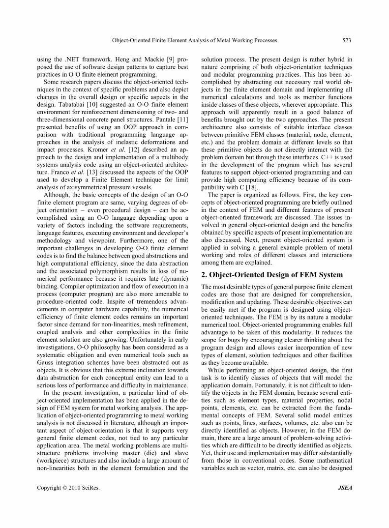
such as ElemType, Material, Node, Element, etc. which are traditional classes used for the representation of finite elements. Several specific classes are derived from these abstract classes. For example, a class Elem2DMfQ8 de-fining two dimensional eight noded metal working quad-rilateral elements is virtually inherited from multiple base classes each having own set of base classes, as depicted in Figure 1.
In most of the earlier investigations, these primitive objects directly interact with the problem domain. How-ever, it can be revealed from the real world concepts that in the FEM domain, some super objects can be identified which are either aggregates of the same objects or a su-perset of different objects. Further, new formalisms and new solution strategies evolve in a regular manner in the FEM field. The implementation of these new techniques in the main class or sub-class of the problem domain must not lead to frequent revisit of classes at lower levels and must not demand for redefinition or major changes in the software architecture. In order to achieve this to a possible extent, we create an interface between the primitive ob-jects and the problem domain by defining classes such as ElemTypeGroup, MaterialGroup, NodeGroup, Ele-mentGroup, etc., which deal with groups of the same type of objects. For example, the ElementGroup class is defined which deals with the lists of elements and per-forms several tasks including assembly of element stiff-ness matrices and load vectors, and the solution of the system equations as depicted in Figure 2. This class is derived from a LinkedList class template and so inherits all its operations for the proper management of the list. The LinkedList class has been defined in template form so that it can take different types of objects (ElemType, Material, Node, Element, etc.) as template arguments. A knowledge base has been incorporated to the LinkedList class which creates and maintains an array of pointers of objects so that an individual item in the list can be found out as efficiently as that in a normal array. The creation of the interface classes (which are properly optimized for numerical efficiency) has provided additional benefits in the modification and extension of the code. On one hand, the primitive classes can be modified, extended and made more efficient independently and on the other hand, modification or extension of main class of the problem domain may require revisit of only the interface classes and doesn’t affect classes at lower levels. The direct in-volvement of interface classes such as the ElementGroup rather than primitive classes or their inheritances also improves the performance during the solution phase since most of the time data are required in vector or matrix form as an aggregate of all the elements or nodes. One of the
Figure 1. An example of inheritance of class Elem2DMfQ8 class ElementGroup : public LinkedList<Element>
private:
/* . . . */
public:
ElementGroup(); // constructor
~ElementGroup(); // destructor
Element* operator[] (int who); // subscript
// operator to reference an element
void Assembly(int loadcase); // assembly of
// stiffness matrices and load vectors
void SkySolve(int loadcase); // skyline
// reduction solution
void FrontSolve(int loadcase); // frontal
// solution
/* . . . */
;
Figure 2. An ElementGroup class dealing with group of elements advantages of this interfacing can also be seen in the class NodeGroup. Since the class Node here is not inherited mainly for efficiency reasons, the class NodeGroup is responsible for distinguishing the functionality of nodes in different types of analyses (static, multi-step, transient, etc.).
As discussed earlier, the metal working problem do-main consists of multiple structures master as well as slave, each having own set of attributes and interacting with one another through the interface. Here, a Struc-tureGroup class is defined which holds a pointer to two master structures (lower die and upper die) and slave structure (workpiece). Each of these structures belongs to
Copyright © 2010 SciRes. JSEA
Object-Oriented Finite Element Analysis of Metal Working Processes 575
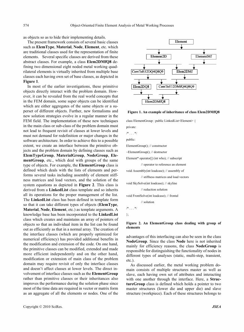
a class Structure defined to contain objects of classes such as ElemTypeGroup, MaterialGroup, NodeGroup, ElementGroup, etc. In many occasions while performing some tasks, the primitive classes may need to retrieve or request some data from the interface classes at higher level. This is done by defining a pointer to Structure within the primitive classes as depicted in diagram shown in Figure 3.
Several other classes, in addition to those discussed above, need to be defined in a complete finite element library. For example, several solid model classes such as Keypoint and KeypointGroup, Line and LineGroup, Area and AreaGroup and Volume and VolumeGroup, are defined that perform modal generation and meshing. Classes Load and Constraint are also defined dealing with loading and constraints as applied to solid model objects and/or nodes and elements. As has become common practice now, some mathematical variables re-quired in the FEM domain such as vector, matrix, etc. have been represented in template form so that they can take variable type (integer, float, double, etc.) as an ar-gument. Engineering variables such as strains and stresses have also been identified as objects. Several utility classes are also defined for the purpose of processing of finite element results and also for managing the finite element objects.
3. Object-Oriented FEM Analysis of Metal Working Process
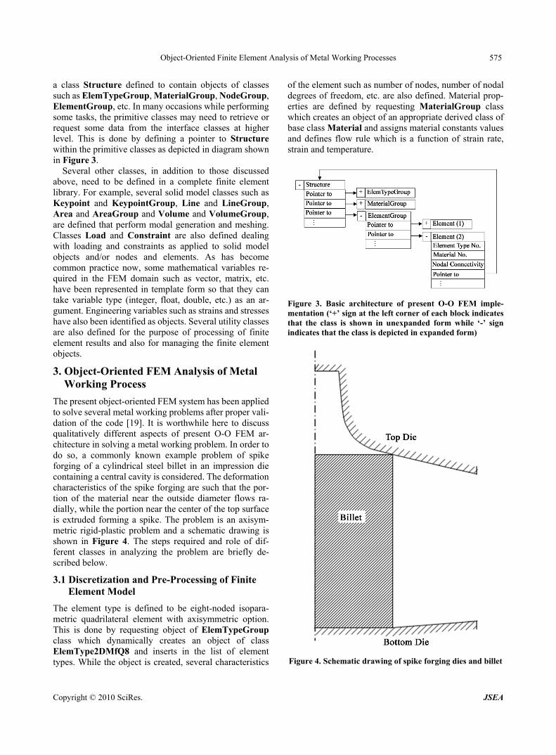
The present object-oriented FEM system has been applied to solve several metal working problems after proper vali- dation of the code [19]. It is worthwhile here to discuss qualitatively different aspects of present O-O FEM ar-chitecture in solving a metal working problem. In order to do so, a commonly known example problem of spike forging of a cylindrical steel billet in an impression die containing a central cavity is considered. The deformation characteristics of the spike forging are such that the por-tion of the material near the outside diameter flows ra-dially, while the portion near the center of the top surface is extruded forming a spike. The problem is an axisym-metric rigid-plastic problem and a schematic drawing is shown in Figure 4. The steps required and role of dif-ferent classes in analyzing the problem are briefly de-scribed below.
3.1 Discretization and Pre-Processing of Finite Element Model
The element type is defined to be eight-noded isopara- metric quadrilateral element with axisymmetric option. This is done by requesting object of ElemTypeGroup class which dynamically creates an object of class ElemType2DMfQ8 and inserts in the list of element types. While the object is created, several characteristics
of the element such as number of nodes, number of nodal degrees of freedom, etc. are also defined. Material prop-erties are defined by requesting MaterialGroup class which creates an object of an appropriate derived class of base class Material and assigns material constants values and defines flow rule which is a function of strain rate, strain and temperature.
Figure 3. Basic architecture of present O-O FEM imple-mentation (‘+’ sign at the left corner of each block indicates that the class is shown in unexpanded form while ‘-’ sign indicates that the class is depicted in expanded form)
Figure 4. Schematic drawing of spike forging dies and billet
Copyright © 2010 SciRes. JSEA

Object-Oriented Finite Element Analysis of Metal Working Processes 576
Solid modelling, mesh control and mesh generation are performed using classes such as KeypointGroup, Line-Group and AreaGroup. While meshing, a number of nodal points are established which are created once the solid model objects request object of class NodeGroup to do so. The coordinates, etc. are assigned to each nodal point during the process. Similarly elements are defined by an object of class ElementGroup which creates ob-jects of class Elem2DMfQ8 based on the element type currently set and arranges them in a list. The data input to each element include the element type reference number, material reference number and element connectivity. Since the current problem is a multi-structure problem involving lower and upper dies and workpiece (Figure 4), most of the above steps are repeated for each of these structures. The meshes of dies and workpiece (deformed) are shown in Figure 5. In this figure, only segments of dies required to define constraints and loading conditions, are modeled and meshed.
3.2 Constraints and Loading
The material flow, which is characterized by spike height variation, depends on the interface friction between die and billet as well as the geometries of dies and billets. Here boundary conditions are prescribed on surfaces of master structures and/or slave structure as appropriate. The die boundary conditions along curved die-workpiece interfaces which constrain flow of material into the die are prescribed using objects of Constraint class defined ap-propriately within each master structure. Similarly, fric-tional boundary conditions are applied using objects of Load class.
3.3 Computation of Element Properties
The rigid-plastic approach states that for a plastically deforming body of volume Ω under surface traction
prescribed on a part of the surface and velocity
prescribed on the remainder of the surface
f
ufΓ
u , the
variational principle (principle of virtual power) can be written as:
Ω Ω Γ 0f
Tv v Γd K d u f d
(1) where is the effective stress defined as )(
and ),( for rigid-plastic and rigid-vis-
coplastic materials respectively, is the effective strain,
is the effective strain-rate and iiv is the volu-
metric strain-rate. K is a penalty constant introduced to impose incompressibility requirement.
In FEM, a continuous velocity field over each element can be defined uniquely in terms of velocities of associ-ated nodal points by introducing the shape function. Equation (1) can now be expressed in terms of nodal point
velocities and their variations U U . From arbi-
trariness of IU , a set of algebraic equations (stiffness
equations) are obtained as
0)(
e eII UU
(2)
where (e) indicates the quantity at the eth element. The capital-letter suffix (I) signifies that it refers to the nodal point number.
In metal-forming, the stiffness Equation (2) is nonlinear and the solution is obtained iteratively by using the Newton-Raphson method. The method consists of lin-earization by Taylor expansion near an assumed solution point 0UU (initial guess), calculating
which is the first-order correction of the velocity ,
and application of suitable convergence criteria to obtain the final solution. After linearization, (2) can be written in the form [20]:
ΔU
0U
Δ]Δ[ RUKT (3)
where is called the tangent stiffness matrix and
is referred to as the vector of residual (out-of-
balance) force increments. These are calculated as sum-mation of contributions from all the elements as
][ TK
ΔR
TK ][e
TK[ e] and , in which is
the element tangent stiffness matrix and is the
vector of increments of element residual force.
e
erR ΔΔ eTK ][
erΔ
Figure 5. Mesh of the workpiece (deformed) and dies in spike forging of a cylindrical steel billet in an impression die containing a central cavity
Copyright © 2010 SciRes. JSEA
Object-Oriented Finite Element Analysis of Metal Working Processes 577
For each element e, and are calculated
by member functions StiffMat() and LoadVect() defined in the class Elem2DMfQ8 or its base classes as appro-priate. Calculating stiffness matrix and load vector require some subtasks to be performed such as calculating shape functions, their partial derivatives, strain-displacement matrix, etc. These subtasks are implemented in the cor-responding element type class ElemType2DMfQ8 or its base classes and are performed when a request is made by element objects. Numerical tools such as numerical inte-gration scheme required for above calculations are em-bedded within an appropriate element class or element type class.
eTK ][ erΔ
3.4 Assemblage of Elements and Solution of Equilibrium Equations
The element tangent stiffness matrices and residual load vectors are assembled to constitute the global tangent stiffness matrix and global residual force vector as dis-cussed above. The function Assembly() defined in the class ElementGroup gets the stiffness matrix and force vector from each element and assembles them in skyline vector storage mode. This compacted storage is used by the skyline reduction solution method SkySolve() to solve the system of equations. Another solution scheme called frontal solution method is implemented by the function FrontSolve(). However, the complete assembly of all element contributions is not required in the case of frontal solution method (FrontSolve()) in which assembly and reduction of equations are performed at the same time. Each of the tasks performed by these member functions is decomposed into smaller tasks executed by different member procedures implemented in this class. Since this phase of finite element solution is computationally inten-sive, the present implementation of this segment is more inclined towards procedure-oriented methodology.
The solution of the system of equations using any of two methods determines the nodal velocity increments (represented in vector form) at a particular iteration in a particular load step. Iteration is continued in a particular load step until convergence is achieved and velocity cor-rection terms become negligibly small. This is followed by calculation of nodal velocities at the load step by the function implemented in NodeGroup class. Here it seems that object-oriented approach has resulted in performance loss by first calculating the degree of freedom variable in vector form and then assigning these values to nodes which are identified as objects. Although for a simple linear static analysis this may be correct, the same is not true in the present case of non-linear multi-step analysis since the kind of variables (nodal velocity increments) calculated by solving the system of equations is different from that assigned to the node which is nodal velocities. Further, this assignment to the nodes takes place only at
the end of a particular step and not at the end of each iteration.
3.5 Computation of Strains/Stresses and Post-Processing of Results
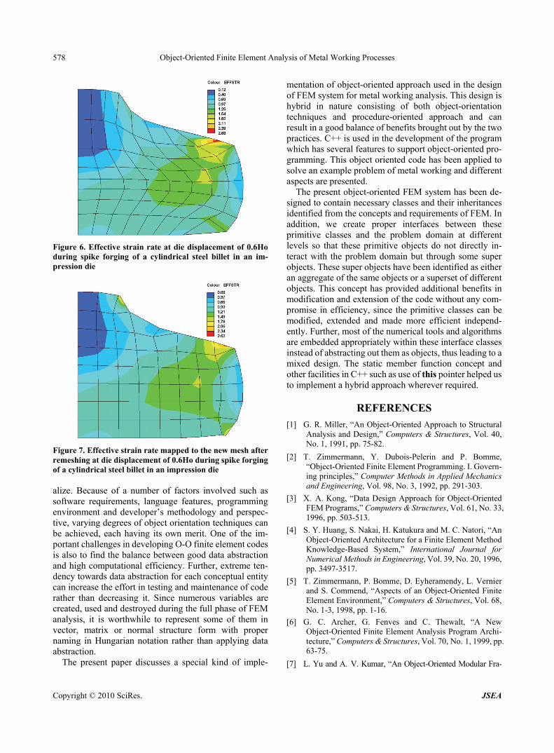
Once the nodal velocities are known, effective strain rates, effective strains and effective stresses within an element are calculated using the member functions defined in the Elem2DMfQ8 class or its base classes. This calculation is invoked by the ElementGroup class before going to the next step. The ElementGroup class is also responsible to save these results in proper file and also prints/plots these results during the solution or at the end of the solution, if and when a request is made. For example, solution of effective strain rate in the mesh of the workpiece at die displacement of 0.6H0 is plotted in Figure 6 as directly obtained by the present implementation of the code.
3.6 Remeshing
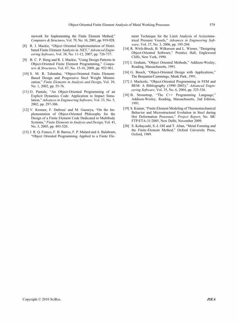
The metal working finite element analysis results in se-vere distortions of mesh and it is essential to frequently refine the mesh or modify some elements during the so-lution phase. Fortunately, the present implementation has one interface class as ElementGroup and another as Structure at a higher level. These interface classes ef-fectively perform remeshing and map the data from the old mesh to the new mesh. Figure 7 depicts the effective strain rate distribution mapped to the new mesh generated by remeshing after the die displacement of 0.6H0.
4. Discussion and Conclusions
In recent past, several investigators have implemented object-oriented techniques in FEM and reported benefits because of this. Object-oriented programming can provide stronger support to desirable features of finite element application programs such as easy testing, maintenance, extension and reusability, than the traditional program-ming.
In object-oriented design, the approach used is to iden-tify and implement a library of finite element data types or classes identified from the real world concept. Each class has well-defined roles and interfaces and therefore can be developed, validated and maintained independently. This approach also permits efficiency concerns to be more easily addressed at the implementation level of each class. The concept of inheritance enables efficient and natural usability of finite element codes. Several new facilities such as new element types, materials and solution tech-niques may be incorporated with much reduced effort.
Although, the objective and general framework of the object-oriented code in these studies are the same, it is not surprising to find some differences in program design leading to the conclusion that a unique (optimized) O-O implementation of FEM system is difficult to conceptu-
Copyright © 2010 SciRes. JSEA
Object-Oriented Finite Element Analysis of Metal Working Processes 578
Figure 6. Effective strain rate at die displacement of 0.6Ho during spike forging of a cylindrical steel billet in an im-pression die
Figure 7. Effective strain rate mapped to the new mesh after remeshing at die displacement of 0.6Ho during spike forging of a cylindrical steel billet in an impression die alize. Because of a number of factors involved such as software requirements, language features, programming environment and developer’s methodology and perspec-tive, varying degrees of object orientation techniques can be achieved, each having its own merit. One of the im-portant challenges in developing O-O finite element codes is also to find the balance between good data abstraction and high computational efficiency. Further, extreme ten-dency towards data abstraction for each conceptual entity can increase the effort in testing and maintenance of code rather than decreasing it. Since numerous variables are created, used and destroyed during the full phase of FEM analysis, it is worthwhile to represent some of them in vector, matrix or normal structure form with proper naming in Hungarian notation rather than applying data abstraction.
The present paper discusses a special kind of imple-
mentation of object-oriented approach used in the design of FEM system for metal working analysis. This design is hybrid in nature consisting of both object-orientation techniques and procedure-oriented approach and can result in a good balance of benefits brought out by the two practices. C++ is used in the development of the program which has several features to support object-oriented pro- gramming. This object oriented code has been applied to solve an example problem of metal working and different aspects are presented.
The present object-oriented FEM system has been de-signed to contain necessary classes and their inheritances identified from the concepts and requirements of FEM. In addition, we create proper interfaces between these primitive classes and the problem domain at different levels so that these primitive objects do not directly in-teract with the problem domain but through some super objects. These super objects have been identified as either an aggregate of the same objects or a superset of different objects. This concept has provided additional benefits in modification and extension of the code without any com- promise in efficiency, since the primitive classes can be modified, extended and made more efficient independ-ently. Further, most of the numerical tools and algorithms are embedded appropriately within these interface classes instead of abstracting out them as objects, thus leading to a mixed design. The static member function concept and other facilities in C++ such as use of this pointer helped us to implement a hybrid approach wherever required.
REFERENCES
[1] G. R. Miller, “An Object-Oriented Approach to Structural Analysis and Design,” Computers & Structures, Vol. 40, No. 1, 1991, pp. 75-82.
[2] T. Zimmermann, Y. Dubois-Pelerin and P. Bomme, “Object-Oriented Finite Element Programming. I. Govern- ing principles,” Computer Methods in Applied Mechanics and Engineering, Vol. 98, No. 3, 1992, pp. 291-303.
[3] X. A. Kong, “Data Design Approach for Object-Oriented FEM Programs,” Computers & Structures, Vol. 61, No. 33, 1996, pp. 503-513.
[4] S. Y. Huang, S. Nakai, H. Katukura and M. C. Natori, “An Object-Oriented Architecture for a Finite Element Method Knowledge-Based System,” International Journal for Numerical Methods in Engineering, Vol. 39, No. 20, 1996, pp. 3497-3517.
[5] T. Zimmermann, P. Bomme, D. Eyheramendy, L. Vernier and S. Commend, “Aspects of an Object-Oriented Finite Element Environment,” Computers & Structures, Vol. 68, No. 1-3, 1998, pp. 1-16.
[6] G. C. Archer, G. Fenves and C. Thewalt, “A New Object-Oriented Finite Element Analysis Program Archi- tecture,” Computers & Structures, Vol. 70, No. 1, 1999, pp. 63-75.
[7] L. Yu and A. V. Kumar, “An Object-Oriented Modular Fra-
Copyright © 2010 SciRes. JSEA
Object-Oriented Finite Element Analysis of Metal Working Processes
Copyright © 2010 SciRes. JSEA
579
mework for Implementing the Finite Element Method,” Computers & Structures, Vol. 79, No. 16, 2001, pp. 919-928.
[8] R. I. Mackie, “Object Oriented Implementation of Distri- buted Finite Element Analysis in .NET,” Advanced Engin- eering Software, Vol. 38, No. 11-12, 2007, pp. 726-737.
[9] B. C. P. Heng and R. I. Mackie, “Using Design Patterns in Object-Oriented Finite Element Programming,” Compu- ters & Structures, Vol. 87, No. 15-16, 2009, pp. 952-961.
[10] S. M. R. Tabatabai, “Object-Oriented Finite Element- Based Design and Progressive Steel Weight Minimi- zation,” Finite Elements in Analysis and Design, Vol. 39, No. 1, 2002, pp. 55-76.
[11] O. Pantale, “An Object-Oriented Programming of an Explicit Dynamics Code: Application to Impact Simu- lation,” Advances in Engineering Software, Vol. 33, No. 5, 2002, pp. 297-306.
[12] V. Kromer, F. Dufossé and M. Gueurya, “On the Im- plementation of Object-Oriented Philosophy for the Design of a Finite Element Code Dedicated to Multibody Systems,” Finite Elements in Analysis and Design, Vol. 41, No. 3, 2005, pp. 493-520.
[13] J. R. Q. Franco, F. B. Barros, F. P. Malard and A. Balabram, “Object Oriented Programming Applied to a Finite Ele-
ment Technique for the Limit Analysis of Axisymme- trical Pressure Vessels,” Advances in Engineering Soft- ware, Vol. 37, No. 3, 2006, pp. 195-204.
[14] R. Wirfs-Brock, B. Wilkerson and L. Wiener, “Designing Object-Oriented Software,” Prentice Hall, Englewood Cliffs, New York, 1990.
[15] I. Graham, “Object Oriented Methods,” Addison-Wesley, Reading, Massachusetts, 1991.
[16] G. Booch, “Object-Oriented Design with Applications,” The Benjamin/Cummings, Menk Park, 1991.
[17] J. Mackerle, “Object-Oriented Programming in FEM and BEM: A Bibliography (1990–2003),” Advanced Engin- eering Software, Vol. 35, No. 6, 2004, pp. 325-336.
[18] B. Stroustrup, “The C++ Programming Language,” Addison-Wesley, Reading, Massachusetts, 2nd Edition, 1991.
[19] S. Kumar, “Finite Element Modeling of Thermomechanical Behavior and Microstructural Evolution in Steel during Hot Deformation Processes,” Project Report, No. SR/ FTP/ETA-31/2005, New Delhi, November 2009.
[20] S. Kobayashi, S.-I. OH and T. Altan, “Metal Forming and the Finite-Element Method,” Oxford University Press, Oxford, 1989.


![Object-oriented programming of adaptive finite element …jinnliu/proj/Device/1996OOP.pdf · Object-oriented programming of adaptive finite element and ... adaptive analysis ... [36]](https://static.fdocuments.net/doc/165x107/5b14d55b7f8b9af15d8c1bb0/object-oriented-programming-of-adaptive-finite-element-jinnliuprojdevice-.jpg)