OBG PRESENTS: Why are My Filters Failing? Forensic ......Comparison of Leopold IMS caps with caps by...
30
OBG PRESENTS: Why are My Filters Failing? Forensic Analysis of Filter Underdrain Failures at WSSC’s 285 MGD Potomac Water Filtration Plant George B. Rest, PE | TRI-ASSOCIATION CONFERENCE August 30, 2017
Transcript of OBG PRESENTS: Why are My Filters Failing? Forensic ......Comparison of Leopold IMS caps with caps by...

OBG PRESENTS:
Why are My Filters Failing? Forensic Analysis of Filter Underdrain Failures at WSSC’s 285 MGD Potomac Water Filtration PlantGeorge B. Rest, PE | TRI-ASSOCIATION CONFERENCE August 30, 2017
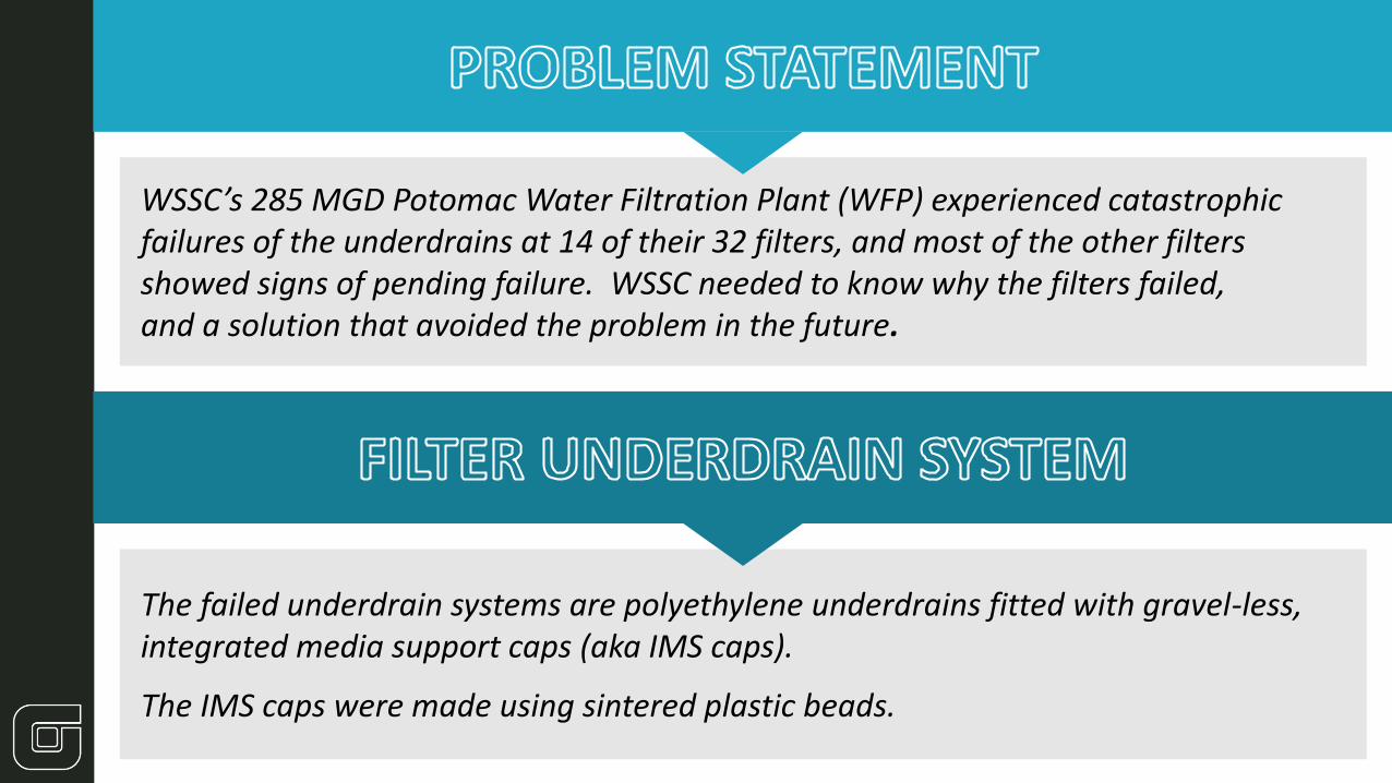
WSSC’s 285 MGD Potomac Water Filtration Plant (WFP) experienced catastrophic failures of the underdrains at 14 of their 32 filters, and most of the other filters showed signs of pending failure. WSSC needed to know why the filters failed, and a solution that avoided the problem in the future.
The failed underdrain systems are polyethylene underdrains fitted with gravel-less, integrated media support caps (aka IMS caps).
The IMS caps were made using sintered plastic beads.
mm
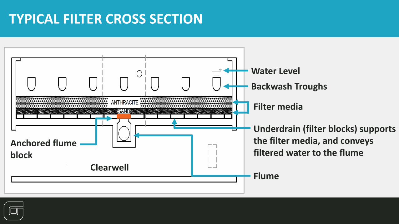
TYPICAL FILTER CROSS SECTION
Flume
Filter media
Underdrain (filter blocks) supports the filter media, and conveys filtered water to the flume
Water Level
Backwash Troughs
Clearwell
Anchored flume block

Existing (Former) Underdrain (“Filter Block”)
IMS Cap
IMS Cap

POTOMAC WFP
Filter Failure History
5
0
2
4
6
8
10
2006 2007 2008 2009 2010 2011 2012 2013 2014 2015 2016
Nu
mb
er
of
failu
res
or
con
curr
en
t o
uta
ges
Filter underdrain failure at Potomac WFP; Annual Statistics
Number of failure occurrences
First-time failures
Concurrent outages
18 reported failure occurrences 14 first time failures;
4 repeat failures
3 filter underdrains replaced by manufacturer
One failed a second time
4 filters repaired Three of which failed a second time
Filter underdrain failures in each of past 10 years

POTOMAC WFP FILTER #5
Catastrophic Underdrain Failures
6
“Catastrophic failures”refer to the underdrain blocks heaving up off the floor of the filter box

POTOMAC WFP FILTER #5
Catastrophic Underdrain Failures
7
Uplift at Filter #5 involved failure of 3/8” steel rods at flume opening, and separation of filter blocks from the grout.
Grout fully separated from plastic block
BACKGROUND

POTOMAC WFP
Catastrophic Underdrain Failures
8
INITIAL “FORENSIC” OBSERVATIONS
▪ Most failures were one block away from the flume, and therefore were not restrained
▪ IMS caps stayed in place, although a few were cracked
▪ Grout quality varies substantially Crumbling grout in filter
Catastrophic failure shown at location NOT over the flume

Step 1: Benchmarking Study Findings
FORENSICS ANALYSIS
Search for Root Causes of Underdrain Failures
Why and Why Now?
9
Similar underdrain failures were attributed to biological growths and “EPS” substances clogging the IMS caps
Similar underdrain failures were attributed to backwash water (uplift force) in flume getting past flume block and under the un-restrained filter blocks
Some failures were attributed to uncontrolled air in the underdrain
Several reports of excessive amounts of filter sand accumulating in the IMS caps.
• IMS cap pores are large enough to allow sand in, but designed for sand to blow-out during backwash

Step 2: Detailed Investigations
FORENSICS ANALYSIS
Search for Root Causes of Underdrain Failures
Why and Why Now?
10
Visual inspection of failed underdrains, and observation of trends related to location of uplifted blocks (relative to flume and restraining rods) grout condition
Review of historical operations data (filter run time and headloss, backwash pressure, etc.) to discern trends in filter performance
Comparison of Leopold IMS caps with caps by other manufacturers, to assess potential for manufacturing differences
Analyze IMS Caps using Electron Transmission Microscopy to determine the chemical constituents of organic and inorganic matter inside the caps
Search for potential sources of uncontrolled air entry into underdrains

11
DETAILED FORENSICS IMS CAPS

12
IMS Cap Testing
Leopold IMS caps were retrieved from Filters #26 and #17
▪ Potomac WFP Leopold caps (below) compared to similar products manufactured by Porex and Genpore
▪ Cap samples submitted to MVA Scientific for microscopy analysis

13
Glazing on bottom of cap
COMPARISON OF IMS CAPS
Leopold sintered bead caps showed “glazing” and extensive occlusion on bottom face (manufacturing defects)
TOP VIEW BOTTOM VIEW
CROSS SECTION

TOP VIEW BOTTOM VIEW
14
COMPARISON OF IMS CAPS
Other manufacturers (Porex) of sintered bed caps showed uniformity in the top and bottom surface

MICROSCOPIC ANALYSIS OF IMS CAPS
15
Pore spaces in Potomac WFP’s IMS caps found to be substantially occluded by penetrating sand and anthracite media, and a fine brown particulate coating.
Sand media filled pore spaces in IMS cap

16
SEM-EDS (scanning electron microscopy-energy dispersive x-ray spectrometry) analysis of a sub-sample of the fine brown particulate revealed silicates (sand), calcium, manganese and aluminum
MICROSCOPIC ANALYSIS OF IMS CAPS

17
SEM-EDS ANALYSIS RESULTS
Confirmed presence of inorganic foulants:
▪ Silicates (sand)
▪ Ca, Mg, Mn (raw water)
▪ Al and Fe (coagulants)
MICROSCOPIC ANALYSIS OF IMS CAPS
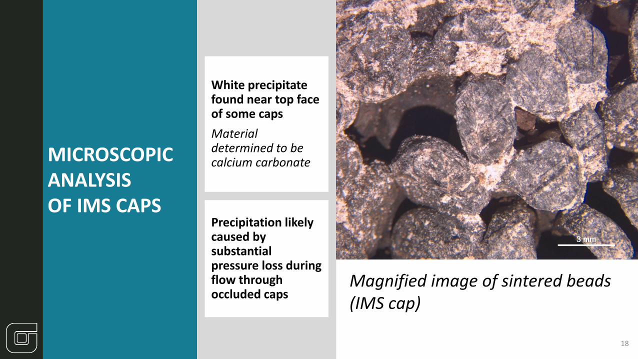
18
Magnified image of sintered beads (IMS cap)
White precipitate found near top face of some caps
Material determined to be calcium carbonate
Precipitation likely caused by substantial pressure loss during flow through occluded caps
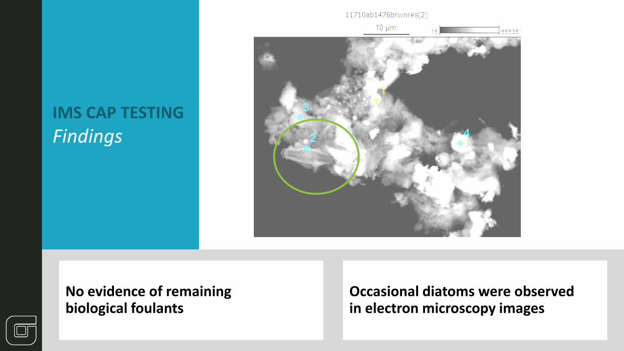
IMS CAP TESTING
Findings
No evidence of remaining biological foulants
Occasional diatoms were observed in electron microscopy images

20
Grout forensic characterization
Poor quality grout observed in a few filters (Filter #21 shown at right)
Competent grout was found in nearly all the other failed filters
▪ However, grout separated from plastic underdrains in all failed filters

21
DETAILED FORENSICS OPERATIONAL PERFORMANCE

22
Trend of Increasing Filter Headloss at Potomac WFP
0
1
2
3
4
5
6
7
8
9
10
11
12
13
14
2004 2005 2006 2007 2008 2009 2010 2011 2012 2013 2014 2015 2016 2017
Hea
dlo
ss (
feet
) af
ter
24
ho
ur
run
at
Filt
er 1
4
Year
Loss of Head Reading Exceeded Max Reading
Air binding starts at 9' headloss
Headloss ≈3' when new
23
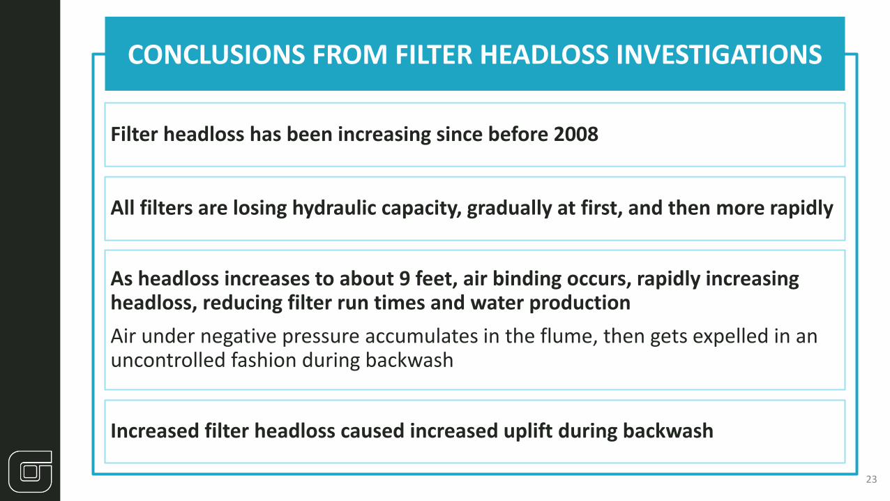
CONCLUSIONS FROM FILTER HEADLOSS INVESTIGATIONS
Filter headloss has been increasing since before 2008
All filters are losing hydraulic capacity, gradually at first, and then more rapidly
As headloss increases to about 9 feet, air binding occurs, rapidly increasing headloss, reducing filter run times and water production
Air under negative pressure accumulates in the flume, then gets expelled in an uncontrolled fashion during backwash
Increased filter headloss caused increased uplift during backwash

24
VIDEO CLIPS SHOW RESULT OF EXCESSIVE HEADLOSS

25
Backwash System Investigations
Two phenomenon introduced air into the underdrains
▪ Recent piping modifications allowed air into the backwash header
▪ Filter box vents allowed air into the flume and underdrain due to excessive head loss
Installed two pressure transmitters on backwash line, and monitored for several months
Did not detect substantial transient spiking

CONCLUSIONS FROM FORENSIC ANALYSIS
It is reasonable to conclude that…
26
Failures are the result of manufacturing defects as the root cause, which allow the embedment of sand, and over time, diminishes the porosity of the caps
All filters have lost hydraulic capacity, gradually at first, and then more rapidly
As headloss increases, calcium carbonate can precipitate and has further fouled some caps
As headloss even further increases, air binding occurs, reducing filter run times and water production
The air in the flume gets expelled during backwash, but the uncontrolled nature of the air release could further contribute to filter failures

CONCLUSIONS FROM FORENSIC ANALYSIS
It is reasonable to conclude that…
27
Backwash pressure, which is now measured continuously, exceeded the uplift design condition, contributing to the failures
Inconsistent grout quality and poor adherence to the plastic blocks impairs the ability of the underdrain to resist uplift, and allows uplift pressure to be applied to the unanchored blocks beyond the flume
Introduction of uncontrolled air during backwash may increase uplift dynamics
Recent controls changes appears to have resolved this issue
It is likely that all the “Leopold” filters will experience conditions outside the basis for design within the next few years.
The best course of action is to replace the underdrains as soon as possible.

28
CURRENT SITUATION
WSSC implemented recommended operational changes and minimized additional failures during past year
WSSC has rebuilt all of the failed filters (16 rebuilt to date) on an accelerated schedule, using new stainless steel slotted underdrains
▪ All laterals are bolted to floor
▪ Minimal reliance on grout
▪ Slots designed to avoid clogging
▪ The remaining filters will be rebuilt in the next year.
New stainless steel underdrains

CONTACT [email protected]
Acknowledgements
29
Joseph Johnson Water Plant Superintendent, WSSC
Tony Dove
Construction Manager, WSSC
Alan Sauvageau Asset Management Group, WSSC (Project Manager)
Fred Pfeifer Asset Management Group, WSSC
Gregory J. Welter PE, BCEEOBG
CO-AUTHORS and CONTRIBUTORS

OBG | THERE’S A WAY